HPS’S CYLINDER SELECTION · HPS’S CYLINDER SELECTION THE CYLINDER MATERIAL AND COMPONENTS The...
15
HPS’S CYLINDER SELECTION CYLINDERS TYPE CATEGORIES Basically, there are three type cylinders categories. 1) BLOC CYLINDERS 2) STANDARDIZED CYLINDERS 3) AUTO LOCKING CYLINDERS
Transcript of HPS’S CYLINDER SELECTION · HPS’S CYLINDER SELECTION THE CYLINDER MATERIAL AND COMPONENTS The...

HPS’S CYLINDER SELECTION
CYLINDERS TYPE CATEGORIES
Basically, there are three type cylinders categories.
� 1) BLOC CYLINDERS
� 2) STANDARDIZED CYLINDERS
� 3) AUTO LOCKING CYLINDERS

2
HPS’S CYLINDER SELECTION
CYLINDERS TYPE CATEGORIES
Basically, there are three type cylinders categories.
� 1) BLOC CYLINDERS � 2) STANDARDIZED CYLINDERS
� 3) AUTO LOCKING CYLINDERS
Use this cylinder to avoid all piping around the tools.
In This family we have 4 different TYPES.
A) Common Bloc Cylinder >> VBL & VBM
B) Small Series Low Cost >> VCN & VXP
C) Average Series Medium Cost >> VBG, VPC & VCR
D) High Series High Quality >> SP2, VSM & VPM
3
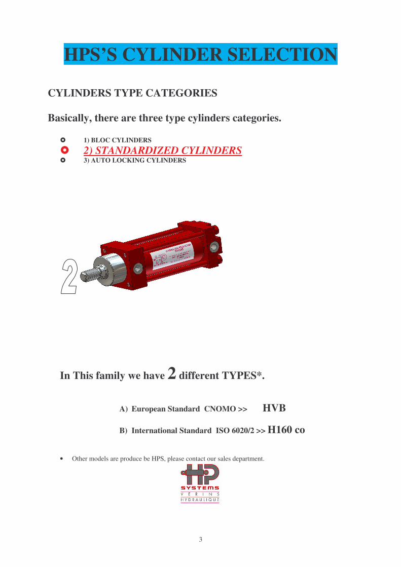
HPS’S CYLINDER SELECTION
CYLINDERS TYPE CATEGORIES
Basically, there are three type cylinders categories.
� 1) BLOC CYLINDERS
� 2) STANDARDIZED CYLINDERS � 3) AUTO LOCKING CYLINDERS
In This family we have 2 different TYPES*.
A) European Standard CNOMO >> HVB
B) International Standard ISO 6020/2 >> H160 co
• Other models are produce be HPS, please contact our sales department.
4
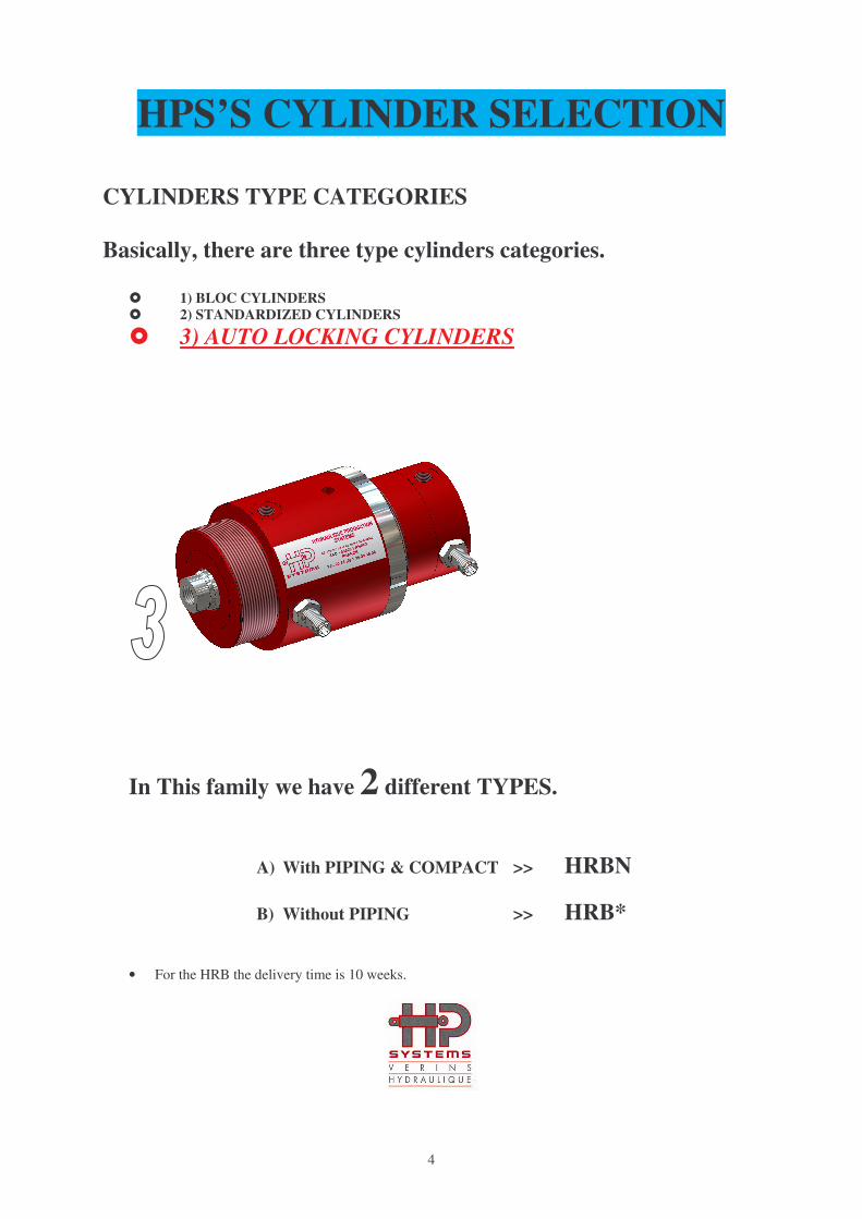
HPS’S CYLINDER SELECTION
CYLINDERS TYPE CATEGORIES
Basically, there are three type cylinders categories.
� 1) BLOC CYLINDERS
� 2) STANDARDIZED CYLINDERS
� 3) AUTO LOCKING CYLINDERS
In This family we have 2 different TYPES.
A) With PIPING & COMPACT >> HRBN
B) Without PIPING >> HRB*
• For the HRB the delivery time is 10 weeks.

5
HPS’S CYLINDER SELECTION
THE CYLINDER MATERIAL AND COMPONENTS
The following chart show the material used for the components of each single cylinder.
COMPONENT MATERIAL
VB
L
VB
M
VC
N
VX
P
VB
G
VP
C
VC
R
SP
2
VS
M
VP
M
HV
B
H1
60
co
HR
BN
Rod 42CD4 hardened and chrome-plated
steel X X X X X X X X X X X X X
Piston
C35E steel X X X X X X X X X X X X
Aluminium (For Magnetic detection) X X X X X X X X X X X
Body
C35E Steel X X X X X X X X X X X X
Stainless Steel (For Magnetic detection)
X X
Aluminium (For Magnetic detection) X X X X X X X X X
Head C35E Steel X X X X X X X X X X X X X
Bottom C35E Steel X X X X X X X X X
Seals
NITRIL (0° < 80°) X X X X X X X X X X X X X
VITON (0° < 160°) X X X X X X X X X X X X X
O-Ring
NITRIL (0° < 80°) X X X X X X X X X X X X X
VITON (0° < 160°) X X X X X X X X X X X X X

6
HPS’S CYLINDER SELECTION
3 TYPES OF DETECTION
ELECTRO/MECANICAL---MAGNETIC---INDUCTIVE
ELECTRO/MECANICAL MAGNETIC INDUCTIVE
ADVANTAGE Simple/reliable/polluted environment No & clean Contact No & clean Contact
DISAVANTAGE Cost/Cumbersome Aluminium Body,
low temperature &
Clean environment
Clean environment
& low temperature
VALUE *** * **
ELECTRO/MECANICAL
7
HPS’S CYLINDER SELECTION
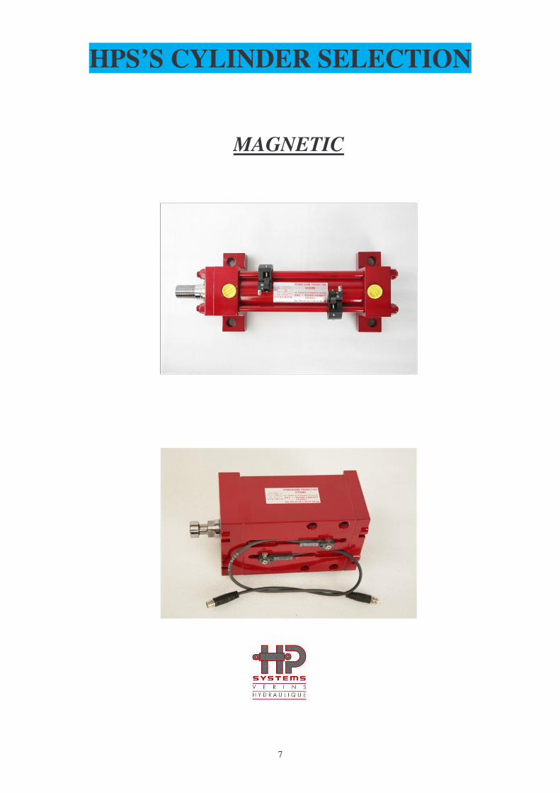
MAGNETIC

8
HPS’S CYLINDER SELECTION
INDUCTIVE

9
HPS’S CYLINDER SELECTION
GENERAL CYLINDER OPERATION ASPECTS
Operating
Principles
A fluid is introduced into a cylindrical chamber where
a sliding piston is free to move. The force exerted by
the fluid on the piston surface generates a working
pressure on the contact are and causes the piston to
move along a specific length of space called stroke.
Force The fluid introduced in the cylinder exerts a force on
the piston surface and causes the piston movement.
Flow Volume of oil that flows into and out of the cylinder
during a unit of time (e.g l/min). Due to different
chamber volumes, at the same flow value, the cylinder
gains greater speed when the piston goes back.
Logically speed is strictly connected to the flow value.
Piston Speed Piston speed is the piston motion rapidity along a given
length of movement (stroke). The speed value is
strictly connected to the cylinder oil flow. Speed is one
of the important factors which determine the cylinder
life. In fact, at given piston impact speed against the
cylinder head will cause permanent damages such as
deformations, breakages, leakages etc...
Pressure Pressure of the oil introduced to – extracted from the
cylinder heads ports. The value is determined by the
nominal pressure of the hydraulic system connected to
the cylinder.
Piston
Cushioning
Cushioning is the result effect of mounting a cushion
bushing on the piston rod and a flow adjusting screw
(in the cylinder heads). In fact, during the piston
motion, the presence of the cushion bushing causes the
generation of a deceleration force at a certain position
along the stroke.

10
HPS’S CYLINDER SELECTION
SELECTING A CYLINDER FOR GENERAL APPLICATION
CONSIDERATIONS ABOUT THE FORCES
The main FORCES exercised during the piston movement are basically TWO.
Look at the following chart to know about them.
PUSH FORCE (Thrust) Force that the fluid exercises on the full piston surface
PULL FORCE (Traction) Force that the fluid exercises on a reduced piston surface
For the cylinder selection you will consider the PUSH and the PULL FORCE.
The PUSH FORCE is BIGGER than the PULL FORCE, since pressure acts on the whole piston area only
on the forward stroke. In fact, on the return stroke pressure does not act on the rod section, which must be
obviously subtracted from the whole piston area.
We must remember that forces are derived from the general formula.
F= P x A
F= Force in Kg
P= bar (Kg/cm²)
A= area in cm²
When you have to select a cylinder, you have to:
1) Consider the FORCES that will be applied to the cylinders (or that your cylinder will apply) in your
particular application and verify, using the manufacturer’s specification, that the CYLINDER
CHOSEN IS SUITABLE.
2) Decide which cylinder family use. (3 different family’s)
3) Decide whether to use a cylinder with DETECTION (3 different family’s)
4) Decide whether to use a cylinder with piston CUSHIONING or not.
PUSH PULL

11
HPS’S CYLINDER SELECTION
STEPS TO SELECT HPS’S CYLINDERS
3 STEPS TO SELECT CYLINDERS FOR MOULD HYDRAULIC SYSTEMS
STEP 1: Select cylinder family on the basis of the following factors.
• PRESSURE of the application hydraulic system
• Movement SPEED requested by the application.
• SPACE to locate the cylinder in the tool.
• Working TEMPERATURE of the system where the cylinder will be located.
• Necessary cylinder STROKE.
• MOUNTING TYPE.
• Pulling and pushing FORCES.
PRESSURE
Two main pressure values are to be considered on injection moulds.
Operating pressure, given by the hydraulic system power circuit
Cylinder pressure, exercised by the cylinder to keep in place mould component and counteract
mould inner pressure on a specific portion surface.
SPEED
You have to verify and calculate the speed if you have long stroke.
For lees than 200mm stroke it’s not necessary.
SPACE
The volume and space allocate for the cylinder can define the type. With or without piping.
TEMPERATURE
The plastic material high temperature is essentially conveyed by heat conduction to outside
area of the mould through the cylinder rod. The temperature in this particular area must be
considered to select the right cylinder and seals. Electronic sensors are very sensitive to high
temperature. Ensure temperature never exceeded 70/80° centigrade.
STROKE
In mould application there are no particular strokes. For safety reasons it’s suitable to have
+1mm stroke in both side of the cylinder. For example the needed stroke is 100mm order
102mm and located the cylinder with 1mm safety stroke in piston side and 1mm safety stroke
in rod side.
12
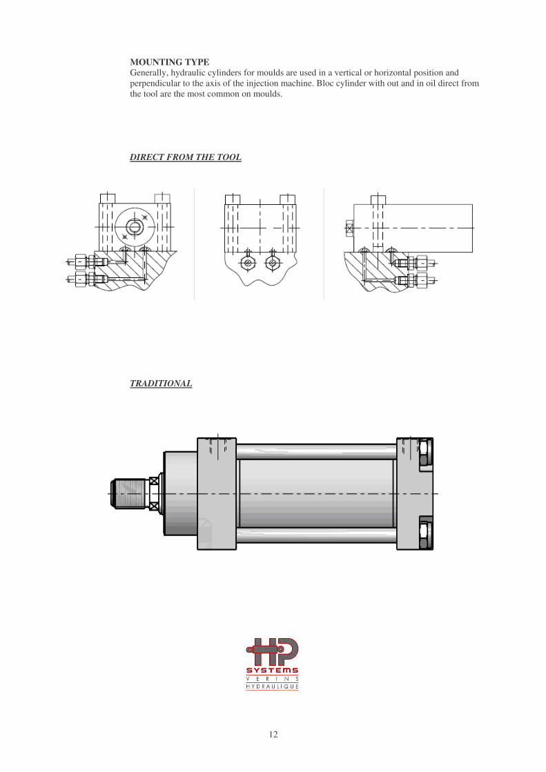
MOUNTING TYPE Generally, hydraulic cylinders for moulds are used in a vertical or horizontal position and
perpendicular to the axis of the injection machine. Bloc cylinder with out and in oil direct from
the tool are the most common on moulds.
DIRECT FROM THE TOOL
TRADITIONAL

13
FORCES
Three types of forces must be considered when selecting a cylinder for injection mould applications.
1) PUSH FORCE (Thrust) DYNAMIC. Push Force exercised by the cylinder to move ejection plates or other moving mould components. In these
cases inertial force and kinetic energy must be considered to prevent damages selecting the proper cylinder.
2) PULL FORCE (Traction). To move back the mould sliding system to release and/or expel the plastic component solidified on the
slider. When that slider has to be extracted, the solidified material exercises a gripping force, that the
cylinder pull force must win, in order to carry out the slider.
Part
Slider
Cavity
CYLINDER
14
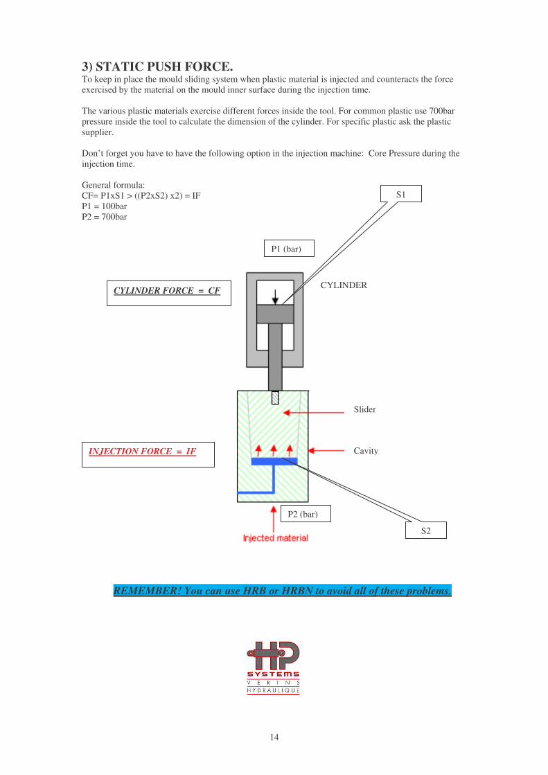
3) STATIC PUSH FORCE. To keep in place the mould sliding system when plastic material is injected and counteracts the force
exercised by the material on the mould inner surface during the injection time.
The various plastic materials exercise different forces inside the tool. For common plastic use 700bar
pressure inside the tool to calculate the dimension of the cylinder. For specific plastic ask the plastic
supplier.
Don’t forget you have to have the following option in the injection machine: Core Pressure during the
injection time.
General formula:
CF= P1xS1 > ((P2xS2) x2) = IF
P1 = 100bar
P2 = 700bar
REMEMBER! You can use HRB or HRBN to avoid all of these problems.
CYLINDER
Slider
Cavity INJECTION FORCE = IF
CYLINDER FORCE = CF
P1 (bar)
P2 (bar)
S1
S2
15
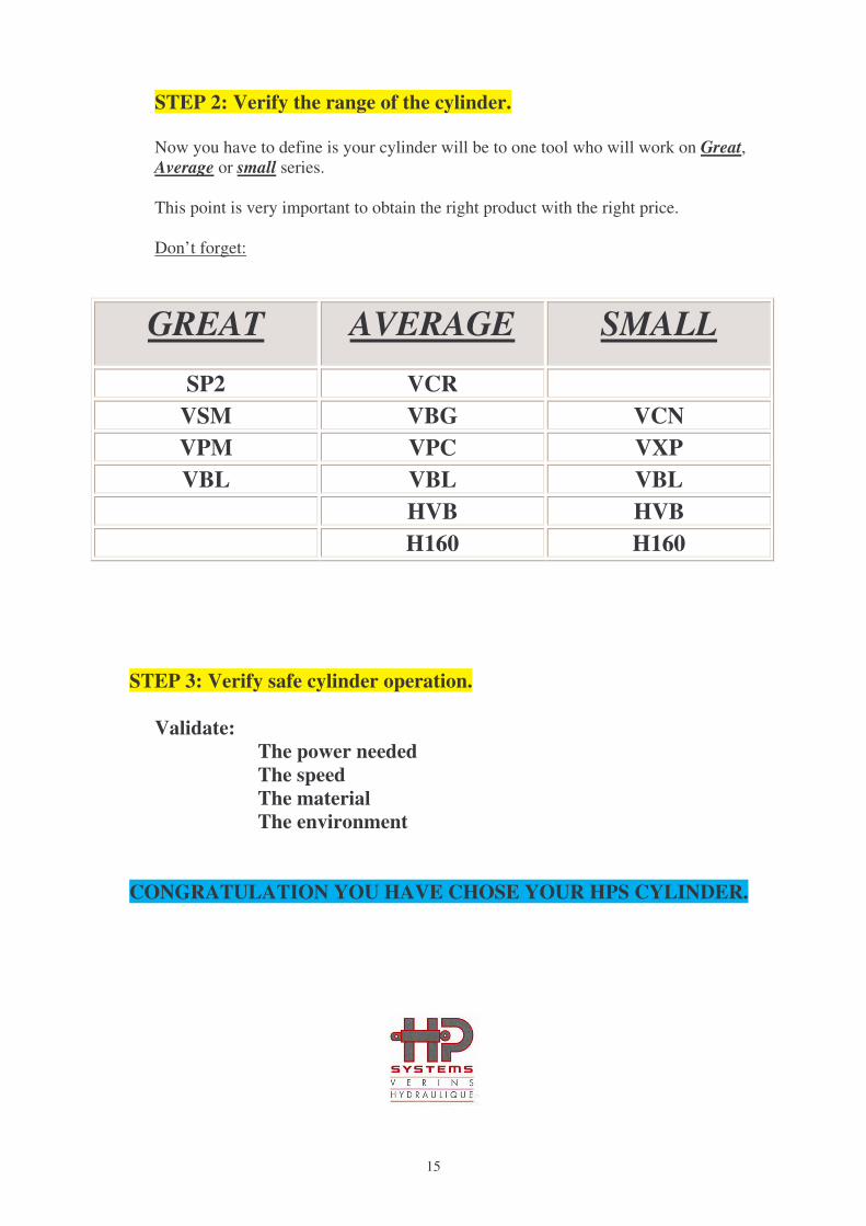
STEP 2: Verify the range of the cylinder.
Now you have to define is your cylinder will be to one tool who will work on Great,
Average or small series.
This point is very important to obtain the right product with the right price.
Don’t forget:
GREAT AVERAGE SMALL
SP2 VCR
VSM VBG VCN
VPM VPC VXP
VBL VBL VBL
HVB HVB
H160 H160
STEP 3: Verify safe cylinder operation.
Validate:
The power needed
The speed
The material
The environment
CONGRATULATION YOU HAVE CHOSE YOUR HPS CYLINDER.