HPE OfficeConnect 1620 Switch Seriesh20628. · The HPE OfficeConnect 1620 Switch Series can be...
210
HPE OfficeConnect 1620 Switch Series User Guide Part number: 5998-5672R Software version: Release 1110 Document version:6W102-20160330
Transcript of HPE OfficeConnect 1620 Switch Seriesh20628. · The HPE OfficeConnect 1620 Switch Series can be...

HPE OfficeConnect 1620 Switch Series User Guide Part number: 5998-5672R Software version: Release 1110 Document version:6W102-20160330

© Copyright 2016 Hewlett Packard Enterprise Development LP
The information contained herein is subject to change without notice. The only warranties for Hewlett Packard Enterprise products and services are set forth in the express warranty statements accompanying such products and services. Nothing herein should be construed as constituting an additional warranty. Hewlett Packard Enterprise shall not be liable for technical or editorial errors or omissions contained herein.
Confidential computer software. Valid license from Hewlett Packard Enterprise required for possession, use, or copying. Consistent with FAR 12.211 and 12.212, Commercial Computer Software, Computer Software Documentation, and Technical Data for Commercial Items are licensed to the U.S. Government under vendor’s standard commercial license.
Links to third-party websites take you outside the Hewlett Packard Enterprise website. Hewlett Packard Enterprise has no control over and is not responsible for information outside the Hewlett Packard Enterprise website.
Acknowledgments
Intel®, Itanium®, Pentium®, Intel Inside®, and the Intel Inside logo are trademarks of Intel Corporation in the United States and other countries.
Microsoft® and Windows® are trademarks of the Microsoft group of companies.
Adobe® and Acrobat® are trademarks of Adobe Systems Incorporated.
Java and Oracle are registered trademarks of Oracle and/or its affiliates.
UNIX® is a registered trademark of The Open Group.

i
Contents
Overview ········································································································· 1
Configuring the switch in the Web interface ···················································· 2
Restrictions and guidelines ································································································································ 2 Operating system requirements ················································································································· 2 Web browser requirements ························································································································ 2 Others ························································································································································ 5
Overview ···························································································································································· 6 Logging in to the Web interface ························································································································· 6 Logging out of the Web interface ······················································································································· 7 Web interface ····················································································································································· 7 Web user level ··················································································································································· 8 Web-based NM functions ··································································································································· 8 Common items on the Web pages ··················································································································· 12
Configuration wizard ····················································································· 16
Basic service setup ·································································································································· 16 Entering the configuration wizard homepage ··························································································· 16 Configuring system parameters ··············································································································· 17 Configuring management IP address ······································································································· 18 Finishing configuration wizard ·················································································································· 19
Displaying system and device information ···················································· 21
Displaying system information ························································································································· 21 Displaying basic system information ········································································································ 21 Displaying the system resource state ······································································································ 22 Displaying recent system logs ·················································································································· 22 Setting the refresh period ························································································································· 22
Displaying device information ·························································································································· 22 Configuring basic device settings ································································· 24
Configuring system name ································································································································ 24 Configuring idle timeout period ························································································································ 24
Maintaining devices ······················································································ 25
Software upgrade ············································································································································· 25 Device reboot ··················································································································································· 26 Electronic label ················································································································································· 26 Diagnostic information ····································································································································· 27
Configuring system time ··············································································· 28
Overview ·························································································································································· 28 Displaying the current system time ·················································································································· 28 Manually configuring the system time ·············································································································· 28 Configuring system time by using NTP ············································································································ 29 Configuring the time zone and daylight saving time ························································································ 30 System time configuration example ················································································································· 31
Network requirements ······························································································································ 31 Configuring the system time ····················································································································· 31 Verifying the configuration ························································································································ 32
Configuration guidelines ·································································································································· 32 Configuring syslog ························································································ 33
Displaying syslogs ··········································································································································· 33 Setting the log host ·········································································································································· 34 Setting buffer capacity and refresh interval ······································································································ 35

ii
Managing the configuration ··········································································· 36
Backing up the configuration ···························································································································· 36 Restoring the configuration ······························································································································ 36 Saving the configuration ·································································································································· 37 Resetting the configuration ······························································································································ 38
Managing files ······························································································· 39
Displaying files ················································································································································· 39 Downloading a file ············································································································································ 39 Uploading a file ················································································································································ 40 Removing a file ················································································································································ 40 Specifying the main boot file ···························································································································· 40
Managing ports ····························································································· 41
Setting operation parameters for a port ··········································································································· 41 Displaying port operation parameters ·············································································································· 44
Displaying a specified operation parameter for all ports ·········································································· 44 Displaying all the operation parameters for a port ··················································································· 45
Port management configuration example ········································································································ 46 Network requirements ······························································································································ 46 Configuring the switch ······························································································································ 46
Configuring port mirroring ············································································· 50
Terminology ····················································································································································· 50 Mirroring source ······································································································································· 50 Mirroring destination ································································································································· 50 Mirroring direction ···································································································································· 50 Mirroring group ········································································································································· 50
Local port mirroring ·········································································································································· 50 Configuration restrictions and guidelines ········································································································· 51 Recommended configuration procedures ········································································································ 51 Configuring a mirroring group ·························································································································· 51 Configuring ports for the mirroring group ········································································································· 52 Local port mirroring configuration example ······································································································ 53
Network requirements ······························································································································ 53 Configuration procedure ··························································································································· 54
Managing users ···························································································· 57
Adding a local user ·········································································································································· 57 Setting the super password ····························································································································· 58 Switching to the management level ················································································································· 59
Configuring a loopback test ·········································································· 60
Configuration guidelines ·································································································································· 60 Configuration procedure ·································································································································· 60
Configuring VCT ··························································································· 62
Overview ·························································································································································· 62 Testing cable status ········································································································································· 62
Configuring the flow interval ·········································································· 63
Viewing port traffic statistics ····························································································································· 63 Configuring energy saving ············································································ 64
Configuring energy saving on a port ················································································································ 64 Configuring SNMP ························································································ 66
Overview ·························································································································································· 66 SNMP mechanism ··································································································································· 66 SNMP protocol versions ··························································································································· 67
Recommended configuration procedure ·········································································································· 67

iii
Enabling SNMP agent ······························································································································ 68 Configuring an SNMP view ······························································································································ 70
Creating an SNMP view ··························································································································· 70 Adding rules to an SNMP view ················································································································· 71
Configuring an SNMP community ···················································································································· 72 Configuring an SNMP group ···························································································································· 73 Configuring an SNMP user ······························································································································ 74 Configuring SNMP trap function ······················································································································ 76 Displaying SNMP packet statistics ··················································································································· 78 SNMPv1/v2c configuration example ················································································································ 78 SNMPv3 configuration example ······················································································································· 81
Displaying interface statistics ········································································ 86
Configuring VLANs ······················································································· 87
Overview ·························································································································································· 87 VLAN fundamentals ································································································································· 87 VLAN types ·············································································································································· 88 Port-based VLAN ····································································································································· 88
Recommended VLAN configuration procedures ······························································································ 90 Recommended configuration procedure for assigning an access port to a VLAN ··································· 90 Recommended configuration procedure for assigning a trunk port to a VLAN ········································ 91 Recommended configuration procedure for assigning a hybrid port to a VLAN ······································ 92
Creating VLANs ··············································································································································· 93 Configuring the link type of a port ···················································································································· 94 Setting the PVID for a port ······························································································································· 95 Selecting VLANs ·············································································································································· 96 Modifying a VLAN ············································································································································ 97 Modifying ports ················································································································································· 98 VLAN configuration example ··························································································································· 99
Network requirements ······························································································································ 99 Configuring Switch A ································································································································ 99 Configuring Switch B ······························································································································ 103
Configuration guidelines ································································································································ 103 Configuring VLAN interfaces ······································································· 104
Overview ························································································································································ 104 Creating a VLAN interface ····························································································································· 104 Modifying a VLAN interface ··························································································································· 105 Configuration guidelines ································································································································ 107
Configuring the MAC address table ···························································· 108
Overview ························································································································································ 108 How a MAC address entry is created ····································································································· 108 Types of MAC address entries ··············································································································· 108
Displaying and configuring MAC address entries ·························································································· 109 Setting the aging time of MAC address entries ······························································································ 110 MAC address table configuration example ···································································································· 110
Network requirements ···························································································································· 110 Creating a static MAC address entry ····································································································· 110
Configuring link aggregation and LACP ······················································ 112
Overview ························································································································································ 112 Basic concepts ······································································································································· 112 Link aggregation modes ························································································································· 113
Configuration procedures ······························································································································· 114 Configuring a static aggregation group ·································································································· 114 Configuring a dynamic aggregation group ····························································································· 115 Creating a link aggregation group ·········································································································· 115 Displaying aggregate interface information ···························································································· 116 Setting LACP priority ······························································································································ 117 Displaying LACP-enabled port information ···························································································· 118

iv
Link aggregation and LACP configuration example ······················································································· 120 Configuration guidelines ························································································································· 122
Configuring IGMP snooping ········································································ 124
Overview ························································································································································ 124 Basic IGMP snooping concepts ············································································································· 124 How IGMP snooping works ···················································································································· 126 Protocols and standards ························································································································ 127
Recommended configuration procedure ········································································································ 127 Enabling IGMP snooping globally ·················································································································· 128 Enabling dropping unknown multicast data globally ······················································································ 129 Configuring IGMP snooping in a VLAN ·········································································································· 129 Configuring IGMP snooping port functions ···································································································· 131 Displaying IGMP snooping multicast forwarding entries ················································································ 132 IGMP snooping configuration example ·········································································································· 133
Network requirements ···························································································································· 133 Configuration procedure ························································································································· 133 Verifying the configuration ······················································································································ 136
Managing services ······················································································ 138
Overview ························································································································································ 138 Managing services ········································································································································· 138
Using diagnostic tools ················································································· 140
Ping ································································································································································ 140 Traceroute ······················································································································································ 140 Ping operation ················································································································································ 141
Configuring IPv4 Ping ···························································································································· 141 Configuring IPv6 Ping ···························································································································· 142
Traceroute operation ······································································································································ 142 Configuring IPv4 traceroute ··················································································································· 142 Configuring IPv6 traceroute ··················································································································· 143
Configuring users ························································································ 145
Configuring a local user ································································································································· 145 Configuring a user group ······························································································································· 147
Managing certificates ·················································································· 149
Overview ························································································································································ 149 PKI terms ··············································································································································· 149 PKI architecture ······································································································································ 149 How PKI works ······································································································································· 150 PKI applications ····································································································································· 151
Recommended configuration procedures ······································································································ 151 Recommended configuration procedure for manual request ································································· 151 Recommended configuration procedure for automatic request ····························································· 153
Creating a PKI entity ······································································································································ 153 Creating a PKI domain ··································································································································· 154 Generating an RSA key pair ·························································································································· 157 Destroying the RSA key pair ·························································································································· 158 Retrieving and displaying a certificate ··········································································································· 158 Requesting a local certificate ························································································································· 160 Retrieving and displaying a CRL ···················································································································· 161 PKI configuration example ····························································································································· 162 Configuration guidelines ································································································································ 167
Configuring loopback detection ··································································· 168
Recommended configuration procedure ········································································································ 168 Configuring loopback detection globally ········································································································ 168 Configuring loopback detection on a port ······································································································ 169

v
Configuring QoS ························································································· 171
Overview ························································································································································ 171 Networks without QoS guarantee ·········································································································· 171 QoS requirements of new applications ·································································································· 171 Congestion: causes, impacts, and countermeasures ············································································ 171 Packet precedences ······························································································································· 173 Queue scheduling ·································································································································· 175 Rate limit ················································································································································ 176 Priority mapping ····································································································································· 178 Introduction to priority mapping tables ··································································································· 179
Recommended QoS configuration procedures ······························································································ 180 Recommended queue scheduling configuration procedure ··································································· 180 Recommended rate limit configuration procedure ················································································· 180 Recommended priority mapping table configuration procedure ····························································· 180 Recommended priority trust mode configuration procedure ·································································· 180
Configuring queue scheduling on a port ········································································································ 180 Configuring rate limit on a port ······················································································································· 181 Configuring priority mapping tables ··············································································································· 182 Configuring priority trust mode on a port ········································································································ 183
QoS configuration example ········································································· 185
Network requirements ···································································································································· 185 Configuring the switch ···································································································································· 185
Document conventions and icons ······························································· 188
Conventions ··················································································································································· 188 Network topology icons ·································································································································· 189
Support and other resources ······································································ 190
Accessing Hewlett Packard Enterprise Support ···························································································· 190 Accessing updates ········································································································································· 190
Websites ················································································································································ 191 Customer self repair ······························································································································· 191 Remote support ······································································································································ 191 Documentation feedback ······················································································································· 191
Index ··········································································································· 193

1
Overview The HPE OfficeConnect 1620 Switch Series can be configured through the Web interface and SNMP/MIB. These configuration methods are suitable for different application scenarios.

2
Configuring the switch in the Web interface
Restrictions and guidelines To ensure a successful login, verify that your operating system and Web browser meet the requirements, and follow the guidelines in this section.
Operating system requirements • The device supports the following operating systems:
Windows XP. Windows 2000. Windows Server 2003 Enterprise Edition. Windows Server 2003 Standard Edition. Windows Vista. Windows 7. Linux. MAC OS.
• If you are using a Windows operating system, turn off the Windows firewall. The Windows firewall limits the number of TCP connections. When the limit is reached, you cannot log in to the Web interface.
Web browser requirements • Hewlett Packard Enterprise recommends that you use the following Web browsers:
Internet Explorer 6 SP2 or higher. Mozilla Firefox 3 or higher. Google Chrome 2.0.174.0 or higher.
• If you are using a Microsoft Internet Explorer browser, you must enable the security settings (see "Enabling securing settings in a Microsoft Internet Explorer browser"), including Run ActiveX controls and plug-ins, Script ActiveX controls marked safe for scripting, and Active scripting.
• If you are using a Mozilla Firefox browser, you must enable JavaScript (see "Enabling JavaScript in a Firefox browser").
Enabling securing settings in a Microsoft Internet Explorer browser 1. Launch the Internet Explorer, and select Tools > Internet Options from the main menu. 2. Select the Security tab, and select the content zone where the target Website resides, as
shown in Figure 1.

3
Figure 1 Internet Explorer settings (1)
3. Click Custom Level. 4. In the Security Settings dialog box, enable Run ActiveX controls and plug-ins, Script
ActiveX controls marked safe for scripting, and Active scripting.

4
Figure 2 Internet Explorer settings (2)
5. Click OK to save your settings.
Enabling JavaScript in a Firefox browser 1. Launch the Firefox browser, and select Tools > Options. 2. In the Options dialog box, click the Content icon, and select Enable JavaScript.

5
Figure 3 Firefox browser settings
3. Click OK to save your settings.
Others • The Web interface does not support the Back, Next, and Refresh buttons provided by the
browser. Using these buttons might result in abnormal display of Web pages. • To ensure correct display of Web page contents after software upgrade or downgrade, clear
data cached by the browser before you log in. • If you click the verification code displayed on the Web login page, you can get a new verification
code. • Up to five users can concurrently log in to the device through the Web interface. • A list can contain a maximum of 20000 entries if displayed in pages. • The PC where you configure the device is not necessarily a Web-based network management
terminal. A Web-based network management terminal is a PC used to log in to the Web interface and is required to be reachable to the device.
• After logging in to the Web interface, you can select Device > Users from the navigation tree, create a new user, and select Wizard or Network > VLAN interface to configure the IP address of the VLAN interface acting as the management interface. For more information, see the corresponding configuration guides of these modules.

6
Overview The device provides web-based configuration interfaces for visual device management and maintenance.
Figure 4 Web-based network management operating environment
Logging in to the Web interface You can use the following default settings to log in to the web interface through HTTP: • Username—admin • Password—None • IP address of VLAN-interface 1 on the device—IP address of the device, depending on the
status of the network where the device resides. If the device is not connected to the network, or no DHCP server exists in the subnet where
the device resides, you can get the IP address of the device on the label on the device. If a DHCP server exists in the subnet where the device resides, the device will dynamically
obtain its IP address through the DHCP server. You can log in to the device through the console port, and execute the summary command to view the information about its IP address. <Sysname> summary
Select menu option: Summary
IP Method: DHCP
IP address: 169.254.1.2
Subnet mask: 255.255.0.0
Default gateway: 0.0.0.0
<Omitted>
Assuming that the IP address of the device is 169.254.1.2, to log in to the Web interface of the device from a PC: 1. Connect the Ethernet interface of the device to a PC by using an Ethernet cable. By default, all
interfaces belong to VLAN 1. 2. Configure an IP address for the PC and make sure that the PC and device can reach each
other. For example, assign the PC an IP address (for example, 169.254.1.27) within 169.254.0.0/16 (except for the IP address of the device).
3. Open the browser, and input the login information. a. Type the IP address http://169.254.1.2 in the address bar and press Enter.
The login page of the web interface (see Figure 5) appears. b. Enter the username admin and the verification code, leave the password blank, and click
Login.

7
Figure 5 Login page of the Web interface
Logging out of the Web interface CAUTION: • You cannot log out by directly closing the browser. • For security purposes, log out of the Web interface after you finish your operations.
1. Save the current configuration. Because the system does not save the current configuration automatically, Hewlett Packard Enterprise recommends that you perform this step to avoid loss of configuration.
2. Click Logout in the upper-right corner of the Web interface.
Web interface The Web interface includes three parts: navigation tree, title area, and body area, as shown in Figure 6.
Figure 6 Web-based configuration interface
(1) Navigation tree (2) Body area (3) Title area
• Navigation tree—Organizes the Web-based NM functions as a navigation tree, where you can select and configure functions as needed. The result is displayed in the body area.

8
• Body area—Allows you to configure and display features. • Title area—On the left, displays the path of the current configuration interface in the navigation
area; on the right, provides the Save button to quickly save the current configuration, the Help button to display the Web-related help information, and the Logout button to log out of the Web interface.
Web user level Web user levels, from low to high, are visitor, monitor, configure, and management. A user with a higher level has all the operating rights of a user with a lower level. • Visitor—Users of this level can only use the network diagnostic tools ping and Trace Route.
They can neither access the device data nor configure the device. • Monitor—Users of this level can only access the device data but cannot configure the device. • Configure—Users of this level can access device data and configure the device, but they
cannot upgrade the host software, add/delete/modify users, or backup/restore configuration files.
• Management—Users of this level can perform any operations to the device.
Web-based NM functions User level in Table 1 indicates that users of this level or users of a higher level can perform the corresponding operations.
Table 1 Web-based NM function description
Function menu Description User level Wizard IP Setup Perform quick configuration of the device. Management
Summary
System Information
Display the basic system information, system resource state, and recent system operation logs. Monitor
Device Information Display the port information about the device. Monitor
Device
Basic System Name Display and configure the system name. Configure
Web Idle Timeout
Display and configure the idle timeout period for logged-in users. Configure
Device Maintenance
Software Upgrade
Upload upgrade file from local host, and upgrade the system software. Management
Reboot Reboot the device. Management
Electronic Label Display the electronic label of the device. Monitor
Diagnostic Information
Generate diagnostic information file and view or save the file to local host. Management
System Time
System Time Display and configure the system date and time. Configure
Time Zone Set system time zone and daylight saving time. Configure
Network TimeProtocol
Display the synchronization status of the system clock and configure the network time. Configure
Syslog Loglist Display and refresh system logs. Monitor
Clear system logs. Configure

9
Function menu Description User level Loghost Display and configure the loghost. Configure
Log Setup Display and configure the buffer capacity and interval for refreshing system logs. Configure
Configuration
Backup Back up the configuration file to be used at the next startup from the device to the host of the current user.
Management
Restore Upload the configuration file to be used at the next startup from the host of the current user to the device.
Management
Save Save the current configuration to the configuration file to be used at the next startup. Configure
Initialize Restore the factory default settings. Management
File Management
File Management
Manage files on the device, such as displaying the file list, downloading a file, uploading a file, and removing a file.
Management
Port Management
Summary Display port information by features. Monitor
Detail Display feature information by ports. Monitor
Setup Create, modify, delete, and enable/disable a port, and clear port statistics. Configure
Port Mirroring
Summary Display the configuration information about a port mirroring group. Monitor
Add Create a port mirroring group. Configure
Remove Remove a port mirroring group. Configure
Modify Port Configure ports for a mirroring group. Configure
Users
Summary Display the brief information about FTP and Telnet users. Monitor
Super Password
Configure a password for a lower-level user to switch from the current access level to the management level.
Management
Create Create an FTP or Telnet user. Management
Modify Modify FTP or Telnet user information. Management
Remove Remove an FTP or a Telnet user. Management
Switch To Management
Switch the current user level to the management level. Monitor
Loopback Loopback Perform loopback tests on Ethernet interfaces. Configure
VCT VCT Check the status of the cables connected to Ethernet ports. Configure
Flow Interval
Port Traffic Statistics
Display the average rate at which the interface receives and sends packets within a specified time interval.
Monitor
Energy Saving Energy Saving Display and configure the energy saving settings
of an interface. Configure

10
Function menu Description User level
SNMP
Setup Display and refresh SNMP configuration and statistics information. Management
Configure SNMP. Management
Community Display SNMP community information. Management
Create, modify, and delete an SNMP community. Management
Group Display SNMP group information. Management
Create, modify, and delete an SNMP group. Management
User Display SNMP user information. Management
Create, modify, and delete an SNMP user. Management
Trap
Display the status of the SNMP trap function and information about target hosts. Management
Enable or disable the SNMP trap function; create, modify, and delete a target host. Management
View Display SNMP view information. Management
Create, modify, and delete an SNMP view. Management
Interface Statistics
Interface Statistics
Display and clear the statistics information about an interface. Configure
Network
VLAN
Select VLAN Select a VLAN range. Monitor
Create Create VLANs. Configure
Port Detail Display the VLAN-related details of a port. Monitor
Detail Display the member port information about a VLAN. Monitor
Modify VLAN Modify the description and member ports of a VLAN. Configure
Modify Port Change the VLAN to which a port belongs. Configure
Remove Remove VLANs. Configure
VLAN Interface
Summary Display information about VLAN interfaces by address type. Monitor
Create Create VLAN interfaces and configure IP addresses for them. Configure
Modify Modify the IP addresses and status of VLAN interfaces. Configure
Remove Remove VLAN interfaces. Configure
MAC MAC
Display MAC address information. Monitor
Create and remove MAC addresses. Configure
Setup Display and configure MAC address aging time. Configure
Link Aggregation
Summary Display information about link aggregation groups. Monitor
Create Create link aggregation groups. Configure
Modify Modify link aggregation groups. Configure
Remove Remove link aggregation groups. Configure

11
Function menu Description User level
LACP Summary Display information about LACP-enabled ports
and their partner ports. Monitor
Setup Set LACP priorities. Configure
IGMP Snooping
Basic
Display global IGMP snooping configuration information or the IGMP snooping configuration information in a VLAN, and the IGMP snooping multicast entry information.
Monitor
Configure IGMP snooping globally or in a VLAN. Configure
Advanced Display the IGMP snooping configuration information on a port. Monitor
Configure IGMP snooping on a port. Configure
Service Service
Display the states of services: enabled or disabled. Configure
Enable/disable services, and set related parameters. Management
Diagnostic Tools
IPv4 Ping Ping an IPv4 address. Visitor
IPv6 ping Ping an IPv6 address. Visitor
IPv4 Traceroute
Perform IPv4 trace route operations. Visitor
IPv6 Traceroute
Perform IPv6 trace route operations. Visitor
Authentication
Users
Local User Display configuration information about local users. Monitor
Create, modify, and remove a local user. Management
User Group Display configuration information about user groups. Monitor
Create, modify, and remove a user group. Management
Certificate Management
Entity Display information about PKI entities. Monitor
Add, modify, and delete a PKI entity. Configure
Domain Display information about PKI domains. Monitor
Add, modify, and delete a PKI domain. Configure
Certificate
Display the certificate information about PKI domains and the contents of a certificate. Monitor
Generate a key pair, destroy a key pair, retrieve a certificate, request a certificate, and delete a certificate.
Configure
CRL Display the contents of the CRL. Monitor
Receive the CRL of a domain. Configure
Security
Loopback Detection
Loopback Detection
Display and configure system loopback detection parameters and port loopback detection parameters.
Configure

12
Function menu Description User level
QoS
Queue Summary Display the queue information about a port. Monitor
Setup Configure a queue on a port. Configure
Line Rate Summary Display line rate configuration information. Monitor
Setup Configure the line rate. Configure
Priority Mapping
Priority Mapping
Display priority mapping table information. Monitor
Modify the priority mapping entries. Configure
Port Priority Port Priority Display port priority and trust mode information. Monitor
Modify port priority and trust mode. Configure
Common items on the Web pages Buttons and icons
Table 2 Commonly used buttons and icons
Button and icon Function
Applies the configuration on the current page.
Cancels the configuration on the current page.
Refreshes the current page.
Clears all entries in a list or all statistics.
Adds an item.
,
Removes the selected items.
Selects all the entries in a list.
Clears selection of all entries in a list.
Buffers but does not apply the configuration of the current step, and enters the next configuration step.
Buffers but does not apply the configuration of the current step, and returns to the previous configuration step.
Applies the configurations of all configuration steps.
Enters the modification page of an item so that you can modify the configurations of the item.
Deletes the item corresponding to this icon.

13
Page display function The Web interface can display contents by pages, as shown in Figure 7. You can set the number of entries displayed per page, and view the contents on the first, previous, next, and last pages, or go to any page that you want to check.
Figure 7 Content display by pages
Search function The Web interface provides you with the basic and advanced searching functions to display only the entries that match specific searching criteria. • Basic search—As shown in Figure 7, type the keyword in the text box above the list, select a
search item from the list and click Search to display the entries that match the criteria. Figure 8 shows an example of searching for entries with source IFNET.
Figure 8 Basic search function example
• Advanced search—As shown in Figure 9, you can click the Advanced Search link to open the advanced search area. Specify the search criteria, and click Apply to display the entries that match the criteria.

14
Figure 9 Advanced search
Take the log entry table shown in Figure 7 as an example.
To search for the log entries with source IFNET and level Error: 1. Click the Advanced Search link, specify the search criteria on the advanced search page as
shown in Figure 10, and click Apply.
Figure 10 Advanced search function example (1)
2. Click the Advanced Search link, specify the search criteria on the advanced search page as shown in Figure 11, and click Apply. The log entries with source IFNET and level Error are displayed as shown in Figure 12.
Figure 11 Advanced search function example (2)

15
Figure 12 Advanced search function example (3)
Sort function On some list pages, the Web interface provides the sorting function to display the entries in a certain order.
The Web interface provides you with the sorting functions to display entries in certain orders.
On a list page, you can click the blue heading item of each column to sort the entries based on the heading item you selected. After your clicking, the heading item is displayed with an arrow beside it as shown in Figure 13. The upward arrow indicates the ascending order, and the downward arrow indicates the descending order.
Figure 13 Sort display

16
Configuration wizard The configuration wizard guides you through configuring the basic service parameters, including the system name, system location, contact information, and management IP address.
Basic service setup
Entering the configuration wizard homepage Select Wizard from the navigation tree.
Figure 14 Configuration wizard homepage

17
Configuring system parameters 1. On the wizard homepage, click Next.
Figure 15 System parameter configuration page
2. Configure the parameters as described in Table 3.
Table 3 Configuration items
Item Description
Sysname
Specify the system name. The system name appears at the top of the navigation tree. You can also set the system name in the System Name page you enter by selecting Device > Basic. For more information, see "Configuring basic device settings."
Syslocation Specify the physical location of the system. You can also set the physical location in the setup page you enter by selecting Device > SNMP. For more information, see "Configuring SNMP."
Syscontact
Set the contact information for users to get in touch with the device vendor for help. You can also set the contact information in the setup page you enter by selecting Device > SNMP. For more information, see "Configuring SNMP."

18
Configuring management IP address
CAUTION: Modifying the management IP address used for the current login terminates the connection to the device. Use the new management IP address to re-log in to the system.
1. On the system parameter configuration page, click Next.
Figure 16 Management IP address configuration page
2. Configure the parameters as described in Table 4.
Table 4 Configuration items
Item Description
Select VLAN Interface
Select a VLAN interface. Available VLAN interfaces are those configured in the page that you enter by selecting Network > VLAN Interface and selecting the Create tab. The IP address of a VLAN interface can be used as the management IP address to access the device. Configure a VLAN interface and its IP address in the page that you enter by selecting Network > VLAN Interface. For more information, see "Configuring VLAN interfaces."

19
Item Description
Admin status
Enable or disable the VLAN interface. When errors occurred in the VLAN interface, disable the interface and then enable the port to bring the port to operate correctly. By default, the VLAN interface is down if no Ethernet ports in the VLAN is up. The VLAN is in the up state if one or more ports in the VLAN are up.
IMPORTANT: Disabling or enabling the VLAN interface does not affect the status of the Ethernet ports in the VLAN. That is, the port status does not change with the VLAN interface status.
Configure IPv4 address
DHCP Configure how the VLAN interface obtains an IPv4 address: • DHCP—Select the option for the VLAN interface to get an IP
address through DHCP. • BOOTP—Select the option for the VLAN interface to get an
IP address through BOOTP. • Manual—Select this option to manually specify an IPv4
address and the mask length for the VLAN interface.
BOOTP
Manual
IPv4 address
Specify an IPv4 address and the mask length for the VLAN interface. Dotted decimal notation is also allowed for the mask length field. These two fields are configurable if Manual is selected. MaskLen
Configure IPv6 link-local address
Auto Configure how the VLAN interface obtains an IPv6 link-local address. • Auto—Select this option for the device to automatically
generate a link-local address based on the link-local address prefix (FE80::/64) and the link layer address of the interface.
• Manual—Select this option to manually assign an IPv6 link-local address to the interface.
Manual
IPv6 address
Specify an IPv6 link-local address for the VLAN interface. This field is configurable if you select Manual. The address prefix must be FE80::/64.
Finishing configuration wizard After finishing the management IP address configuration, click Next.
The page displays your configurations. Review the configurations and if you want to modify the settings click Back to go back to the page. Click Finish to confirm your settings and the system performs the configurations.

20
Figure 17 Configuration complete

21
Displaying system and device information
Displaying system information Select Summary from the navigation tree to enter the System Information page to view the basic system information, system resource state, and recent system logs.
Figure 18 System information
Displaying basic system information Table 5 Field description
Item Description Product Information Description for the device.
Device Location Device location, which you can configure on the page you enter by selecting Device > SNMP > Setup.
Contact Information Contact information, which you can configure on the page you enter by selecting Device > SNMP > Setup.
SerialNum Serial number of the device.
Software Version Software version of the device.
Hardware Version Hardware version of the device.
Bootrom Version Boot ROM version of the device.

22
Item Description Running Time System up time.
Displaying the system resource state The System Resource State area displays the most recent CPU usage, memory usage, and temperature.
Displaying recent system logs Table 6 Field description
Field Description Time Time when the system logs were generated.
Level Severity of the system logs.
Description Description for the system logs.
The System Information page displays up to five the most recent system logs.
To display more system logs, click More to enter the Log List page. You can also enter this page by selecting Device > Syslog. For more information, see "Configuring syslog."
Setting the refresh period To set the interval for refreshing system information, select one of the following options from the Refresh Period list: • If you select a certain period, the system refreshes system information at the specified interval. • If you select Manual, the system refreshes system information only when you click the Refresh
button.
Displaying device information Select Summary from the navigation tree, and click the Device Information tab to enter the page that displays information about the device ports. Hover the cursor over a port and the port details appear, including the port name, type, speed, utilization, and status, as shown in Figure 19. The aggregation group number is also displayed if the port is added to an aggregation group. For the description about the port number and its color, see Figure 19.

23
Figure 19 Device information
To set the interval for refreshing device information, select one of the following options from the Refresh Period list: • If you select a certain period, the system refreshes device information at the specified interval. • If you select Manual, the system refreshes device information only when you click the Refresh
button.

24
Configuring basic device settings The device basic information feature provides the following functions: • Set the system name of the device. The configured system name is displayed on the top of the
navigation bar. • Set the idle timeout period for logged-in users. The system logs an idle user off the Web for
security purpose after the configured period.
Configuring system name 1. Select Device > Basic from the navigation tree.
The system name configuration page appears.
Figure 20 Configuring the system name
2. Enter the system name. 3. Click Apply.
Configuring idle timeout period 1. Select Device > Basic from the navigation tree. 2. Click the Web Idle Timeout tab.
The page for configuring idle timeout period appears.
Figure 21 Configuring the idle timeout period
3. Set the idle timeout period for logged-in users. 4. Click Apply.

25
Maintaining devices
Software upgrade CAUTION:
Software upgrade takes some time. Avoid performing any operation on the Web interface during the upgrading procedure. Otherwise, the upgrade operation may be interrupted.
A boot file, also known as the system software or device software, is an application file used to boot the device. Software upgrade allows you to obtain a target application file from the local host and set the file as the boot file to be used at the next reboot. In addition, you can select whether to reboot the device to bring the upgrade software into effect. 1. Select Device > Device Maintenance from the navigation tree to enter the Software Upgrade
tab.
Figure 22 Software upgrade configuration page
2. Configure software upgrade parameters as described in Table 7. 3. Click Apply.
Table 7 Configuration items
Item Description
File Specify the path and filename of the local application file, which must be suffixed with the .app or .bin extension.
File Type Specify the type of the boot file for the next boot: • Main—Boots the device. • Backup—Boots the device when the main boot file is unavailable.
If a file with the same name already exists, overwrite it without any prompt
Specify whether to overwrite the file with the same name. If you do not select the option, when a file with the same name exists, a dialog box appears, telling you that the file already exists and you cannot continue the upgrade.
Reboot after the upgrade finished
Specify whether to reboot the device to make the upgraded software take effect after the application file is uploaded.

26
Device reboot CAUTION: • Before rebooting the device, save the configuration. Otherwise, all unsaved configuration will be
lost after device reboot. • When the device reboots, re-log in to the device.
1. Select Device > Device Maintenance from the navigation tree. 2. Click the Reboot tab.
Figure 23 Device reboot page
3. Enable or disable the "Check whether the current configuration is saved in the next startup configuration file" option.
4. Click Reboot. A confirmation dialog box appears. 5. Click OK.
If you select Check whether the current configuration is saved in the next startup configuration file, the system will check the configuration before rebooting the device. If the check succeeds, the system reboots the device. If the check fails, a dialog box appears, telling you that the current configuration and the saved configuration are inconsistent, and the device is not rebooted. In this case, save the current configuration manually before you can reboot the device.
If you do not select the box, the system reboots the device directly.
Electronic label Electronic label allows you to view information about the device electronic label, which is also known as the permanent configuration data or archive information. The information is written into the storage medium of a device or a card during the debugging and testing processes, and includes card name, product bar code, MAC address, debugging and testing dates, and manufacture name. 1. Select Device > Device Maintenance from the navigation tree. 2. Click the Electronic Label tab to view the electronic label information.
Figure 24 Electronic label

27
Diagnostic information Each functional module has its own running information. Generally, you view the output for each module one by one. To receive as much information as possible in one operation during daily maintenance or when system failure occurs, the diagnostic information module allows you to save the running statistics of multiple functional modules to a file named default.diag, and then you can locate problems faster by checking this file. 1. Select Device > Device Maintenance from the navigation tree. 2. Click the Diagnostic Information tab.
Figure 25 Diagnostic information
3. Click Create Diagnostic Information File. The system begins to generate a diagnostic information file.
4. Click Click to Download. The File Download dialog box appears.
5. Select to open this file or save this file to the local host.
Figure 26 The diagnostic information file is created
The generation of the diagnostic file takes a period of time. During this process, do not perform any operation on the Web page.
After the diagnostic file is generated successfully, you can view this file on the page you enter by selecting Device > File Management, or downloading this file to the local host. For more information, see "Managing files."

28
Configuring system time
Overview You must configure a correct system time so that the device can operate correctly with other devices. The system time module allows you to display and set the device system time on the Web interface.
You can set the system time through manual configuration or network time protocol (NTP) automatic synchronization.
Defined in RFC 1305, the NTP synchronizes timekeeping among distributed time servers and clients. NTP can keep consistent timekeeping among all clock-dependent devices within the network, and ensure a high clock precision so that the devices can provide diverse applications based on consistent time.
Displaying the current system time To view the current system date and time, select Device > System Time from the navigation tree to enter the System Time page.
Figure 27 System time configuration page
Manually configuring the system time 1. Select Device > System Time from the navigation tree.
The page for configuration the system time appears. 2. Click the System Time Configuration text to open a calendar.
Figure 28 Calendar page

29
3. Enter the system date and time in the Time field, or select the date and time in the calendar. To set the time on the calendar page, select one of the following methods:
Click Today. The date setting in the calendar is synchronized to the current local date configuration, and the time setting does not change.
Select the year, month, date, and time, and then click OK. 4. Click Apply on the system time configuration page to save your configuration.
Configuring system time by using NTP 1. Select Device > System Time from the navigation tree. 2. Click the Network Time Protocol tab.
The page for configuring the system time through NTP appears.
Figure 29 NTP configuration page
3. Configure the system time as described in Table 8. 4. Click Apply.
Table 8 Configuration items
Item Description Clock status Display the synchronization status of the system clock.
Source Interface
Set the source interface for an NTP message. This configuration makes the source IP address in the NTP messages the primary IP address of this interface. If the specified source interface is down, the source IP address is the primary IP address of the egress interface.
TIP: If you do not want the IP address of an interface on the local device to become the destination address of response messages, specify the source interface for NTP messages.

30
Item Description Key 1 Set NTP authentication key.
Enable the NTP authentication feature for a system running NTP in a network that requires high security. This feature improves the network security by means of client-server key authentication, and prohibits a client from synchronizing with a device that has failed authentication. You can set two authentication keys, each of which has a key ID and a key string. • ID—ID of a key. • Key string—Character string of the MD5 authentication key.
Key 2
External Reference Source
NTP Server 1/Reference Key ID.
Specify the IP address of an NTP server, and configure the authentication key ID used for the association with the NTP server. The device synchronizes its time to the NTP server only if the key provided by the server is the same as the specified key. You can configure two NTP servers. The clients choose the optimal reference source.
IMPORTANT: The IP address of an NTP server is a unicast address, and cannot be a broadcast or a multicast address, or the IP address of the local clock source.
NTP Server 2/Reference Key ID.
Configuring the time zone and daylight saving time
1. Select Device > System Time from the navigation tree. 2. Click the Time Zone tab.
The time zone configuration page appears.
Figure 30 Setting the time zone
3. Configure the time zone and daylight saving time as described in Table 9. 4. Click Apply.
Table 9 Configuration items
Item Description Time Zone Set the time zone for the system.

31
Item Description
Adjust clock for daylight saving time changes
Adjust the system clock for daylight saving time changes, which means adding one hour to the current system time. Click Adjust clock for daylight saving time changes to expand the option, as shown in Figure 31. You can configure the daylight saving time changes in the following ways: • Specify that the daylight saving time starts on a specific date and ends on
a specific date. The time range must be greater than one day and smaller than one year. For example, configure the daylight saving time to start on August 1st, 2006 at 06:00:00 a.m., and end on September 1st, 2006 at 06:00:00 a.m.
• Specify that the daylight saving time starts and ends on the corresponding specified days every year. The time range must be greater than one day and smaller than one year. For example, configure the daylight saving time to start on the first Monday in August at 06:00:00 a.m., and end on the last Sunday in September at 06:00:00 a.m.
Figure 31 Setting the daylight saving time
System time configuration example Network requirements
As shown in Figure 32: • The local clock of Device A is set as the reference clock. • Switch B operates in client mode, and uses Device A as the NTP server.
Configure NTP authentication on Device A and Switch B so that Switch B is to be synchronized to Device A.
Figure 32 Network diagram
Configuring the system time 1. Configure the local clock as the reference clock, with the stratum of 2. Enable NTP
authentication, set the key ID to 24, and specify the created authentication key aNiceKey as a trusted key. (Details not shown.)
2. On Switch B, configure Device A as the NTP server: a. Select Device > System Time from the navigation tree. b. Click the Network Time Protocol tab.

32
c. Enter 24 in the ID field, enter aNiceKey in the Key String field for key 1, enter 1.0.1.11 in the NTP Server 1 field, and enter 24 in the Reference Key ID field.
d. Click Apply.
Figure 33 Configuring Device A as the NTP server of Switch B
Verifying the configuration After the configuration, verify that Device A and Switch B have the same system time.
Configuration guidelines When you configure the system time, follow these guidelines: • A device can act as a server to synchronize the clock of other devices only after its clock has
been synchronized. If the clock of a server has a stratum level higher than or equal to the level of a client's clock, the client will not synchronize its clock to the server's.
• The synchronization process takes some time. The clock status might be displayed as unsynchronized after your configuration. In this case, refresh the page to view the clock status and system time later on.
• If the system time of the NTP server is ahead of the system time of the device, and the time gap exceeds the Web idle time specified on the device, all online Web users are logged out because of timeout after the synchronization finishes.

33
Configuring syslog System logs record network and device information, including running status and configuration changes. With system logs, administrators can take corresponding actions against network problems and security problems.
The system sends system logs to the following destinations: • Console. • Monitor terminal, a terminal that has logged in to the device through the AUX or VTY user
interface. • Log buffer. • Log host. • Web interface. • Log file.
Displaying syslogs 1. Select Device > Syslog from the navigation tree.
The page for displaying syslogs appears. You can click Reset to clear all system logs saved in the log buffer on the Web interface. You can click Refresh to manually refresh the page, or you can set the refresh interval on the Log Setup page to enable the system to automatically refresh the page periodically. For more information, see "Setting buffer capacity and refresh interval."
Figure 34 Displaying syslogs
2. View system logs.
Table 10 Field description
Field Description Time/Date Displays the time/date when the system log was generated.

34
Field Description Source Displays the module that generated the system log.
Level
Displays the severity level of the system log. The information is classified into eight levels by severity: • Emergency—The system is unusable. • Alert—Action must be taken immediately. • Critical—Critical condition. • Error—Error condition. • Warning—Warning condition. • Notification—Normal but significant condition. • Information—Informational message. • Debug—Debug-level message.
Digest Displays the brief description of the system log.
Description Displays the content of the system log.
Setting the log host 1. Select Device > Syslog from the navigation tree. 2. Click the Loghost tab.
The log host configuration page appears.
Figure 35 Setting the log host
3. Configure the log host as described in Table 11. 4. Click Apply.

35
Table 11 Configuration items
Item Description IPv4/Domain Specify the IPv4 address or domain
name of the log host. IMPORTANT:
You can specify up to four log hosts.
Loghost IP/Domain
IPv6 Set the IPv6 address of the log host.
Loghost IP
Setting buffer capacity and refresh interval 1. Select Device > Syslog from the navigation tree. 2. Click the Log Setup tab.
The syslog configuration page appears.
Figure 36 Syslog configuration page
3. Configure buffer capacity and refresh interval as described in Table 12. 4. Click Apply.
Table 12 Configuration items
Item Description Buffer Capacity Set the number of logs that can be stored in the log buffer.
Refresh Interval
Set the log refresh interval. You can select manual refresh or automatic refresh: • Manual—Click Refresh to view the latest log information. • Automatic—Select to refresh the Web interface every 1 minute, 5 minutes,
or 10 minutes.

36
Managing the configuration You can back up, restore, save, or reset the device configuration.
Backing up the configuration Configuration backup allows you to do the following: • Open and view the configuration files for the next startup, including the .cfg file and .xml file. • Back up the configuration files for the next startup to your local host.
IMPORTANT: Hewlett Packard Enterprise recommends backing up both the .cfg and .xml files. If you back up only the .cfg file, some configuration information might not be restored when, for example, the configuration is mistakenly removed.
To back up the configuration: 1. Select Device > Configuration from the navigation tree.
The Backup page appears.
Figure 37 Backing up the configuration
2. Click the upper Backup button. The file download dialog box appears.
3. Choose to view the .cfg file or to save the file to your local host. 4. Click the lower Backup button.
The file download dialog box appears. 5. Choose to view the .xml file or to save the file to the local host.
Restoring the configuration Configuration restoration allows you to do the following: • Upload a .cfg file from your local host to the device. • Upload an .xml file from your local host to the device, and delete the .xml configuration file that
was used for the next startup.
The restored configuration takes effect at the next device startup.
To restore the configuration: 1. Select Device > Configuration from the navigation tree. 2. Click the Restore tab.

37
Figure 38 Restoring the configuration
3. Click the upper Browse button. The file upload dialog box appears.
4. Select the .cfg file to be uploaded, and click OK. 5. Click the lower Browse button.
The file upload dialog box appears. 6. Select the .xml file to be uploaded, and click OK.
Saving the configuration You save the running configuration to both the .cfg configuration file and .xml configuration file that will be used at the next startup.
Saving the configuration takes some time.
Only one administrator can save the configuration at a moment. If you save the configuration while the system is saving the configuration as required by another administrator, the system prompts you to try again later.
You can save the configuration in either of the following modes: • Fast mode.
To save the configuration in fast mode, click the Save button at the upper right of the auxiliary area.
Figure 39 Saving the configuration
• Common mode. To save the configuration in common mode:

38
a. Select Device > Configuration from the navigation tree. b. Click the Save tab. c. Click Save Current Settings.
Resetting the configuration Resetting the configuration restores the device's factory defaults, deletes the current configuration files, and reboots the device.
To reset the configuration: 1. Select Device > Configuration from the navigation tree. 2. Click the Initialize tab. 3. Click Restore Factory-Default Settings.
Figure 40 Resetting the configuration

39
Managing files The device requires a series of files for correct operation, including boot files and configuration files. These files are saved on the storage media. You can display files on the storage media, download, upload, or remove a file, or specify the main boot file.
Displaying files 1. Select Device > File Management from the navigation tree.
Figure 41 File management page
2. Select a medium from the Please select disk list. Two categories of information are displayed:
Medium information, including the used space, the free space, and the capacity of the medium.
File information, including all files on the medium, the file sizes, and the boot file types (Main or Backup). The boot file type is only displayed for an application file (.bin or .app file) that will be used as the main or backup boot file.
Downloading a file 1. Select Device > File Management from the navigation tree to enter the file management page
(see Figure 41). 2. From the Please select disk list, select the medium where the file to be downloaded resides. 3. Select the file from the list.
Only one file can be downloaded at a time. 4. Click Download File.
The File Download dialog box appears. 5. Open the file or save the file to a path.

40
Uploading a file IMPORTANT:
Uploading a file takes some time. Hewlett Packard Enterprise recommends not performing any operation on the Web interface during the upload.
1. Select Device > File Management from the navigation tree to enter the file management page (see Figure 41).
2. In the Upload File area, select the medium for saving the file from the Please select disk list. 3. Click Browse to navigate to the file to be uploaded. 4. Click Apply.
Removing a file 1. Select Device > File Management from the navigation tree to enter the file management page
(see Figure 41). 2. Do one of the following:
Click the icon of a file to remove the file. Select a file from the file list and click Remove File.
To remove multiple files, repeat step 2, or select the files from the file list and click Remove File.
Specifying the main boot file 1. Select Device > File Manage from the navigation tree to enter the file management page
(see Figure 41). 2. From the Please select disk list, select the medium that holds the application file to be used as
the main boot file. 3. Select the application file (.bin or .app file) from the file list. 4. Click Set as Main Boot File.

41
Managing ports You can use the port management feature to set and view the operation parameters of a Layer 2 Ethernet port and an aggregate interface. • For a Layer 2 Ethernet port, these operation parameters include its state, speed, duplex mode,
link type, PVID, description, MDI mode, flow control settings, MAC learning limit, and storm suppression ratios.
• For an aggregate interface, these operation parameters include its state, link type, PVID, description, and MAC learning limit.
Setting operation parameters for a port 1. Select Device > Port Management from the navigation tree. 2. Click the Setup tab.
Figure 42 The Setup tab
3. Set the operation parameters for the port as described in Table 13. 4. Click Apply.

42
Table 13 Configuration items
Item Description
Port State Enable or disable the port. Sometimes, after you modify the operation parameters of a port, you must disable and then enable the port to have the modifications take effect.
Speed
Set the transmission speed of the port: • 10—10 Mbps. • 100—100 Mbps. • 1000—1000 Mbps. • Auto—Autonegotiation. • Auto 10—Autonegotiated to 10 Mbps. • Auto 100—Autonegotiated to 100 Mbps. • Auto 1000—Autonegotiated to 1000 Mbps. • Auto 10 100—Autonegotiated to 10 or 100 Mbps. • Auto 10 1000—Autonegotiated to 10 or 1000 Mbps. • Auto 100 1000—Autonegotiated to 100 or 1000 Mbps. • Auto 10 100 1000—Autonegotiated to 10, 100, or 1000 Mbps.
Duplex
Set the duplex mode of the port: • Auto—Autonegotiation. • Full—Full duplex. • Half—Half duplex.
Link Type
Set the link type of the current port, which can be access, hybrid, or trunk. For more information, see "Configuring VLANs." To change the link type of a port from trunk to hybrid, or vice versa, you must first set its link type to access.
PVID
Set the port VLAN ID (PVID) of the interface. For more information about setting the PVID, see "Configuring VLANs." To make sure a link correctly transmits packets, the trunk or hybrid ports at the two ends of the link must have the same PVID.
Description Set the description of the port.

43
Item Description
MDI
Set the MDI mode of the port. You can use two types of Ethernet cables to connect Ethernet devices: crossover cable and straight-through cable. To accommodate these two types of cables, an Ethernet port can operate in one of the following three MDI modes: across, normal, and auto. An Ethernet port is composed of eight pins. By default, each pin has its particular role. For example, pin 1 and pin 2 are used for transmitting signals, and pin 3 and pin 6 are used for receiving signals. You can change the pin roles by setting the MDI mode. • For an Ethernet port in across mode, pin 1 and pin 2 are used for transmitting
signals, and pin 3 and pin 6 are used for receiving signals. The pin roles are not changed.
• For an Ethernet port in auto mode, the pin roles are decided through autonegotiation.
• For an Ethernet port in normal mode, the pin roles are changed. Pin 1 and pin 2 are used for receiving signals, and pin 3 and pin 6 are used for transmitting signals.
To enable normal communication, you must connect the local transmit pins to the remote receive pins. Configure the MDI mode depending on the cable types. When you configure the MID mode, follow these guidelines: • Typically, use the auto mode. The other two modes are used only when the device
cannot determine the cable type. • When straight-through cables are used, the local MDI mode must be different from
the remote MDI mode. • When crossover cables are used, the local MDI mode must be the same as the
remote MDI mode, or the MDI mode of at least one end must be set to auto.
Flow Control
Enable or disable flow control on the port. With flow control enabled at both sides, when traffic congestion occurs on the ingress port, the ingress port sends a Pause frame notifying the egress port to temporarily suspend the sending of packets. The egress port is expected to stop sending any new packet when it receives the Pause frame. In this way, flow control helps to avoid dropping of packets. Flow control works only after it is enabled on both the ingress and egress ports.
Power Save
Enable or disable auto power-down on a port that is down. By default, auto power-down is disabled on an Ethernet port that is down. With auto power-down enabled on an Ethernet port that stays in the down state for a certain period, the following events occur: • The device automatically stops supplying power to the port. • The port enters the power save mode. When the Ethernet port comes up, the following events occur: • The device automatically restores power supply to the port. • The port resumes its normal state.
Max MAC Count Set the MAC learning limit on the port: • User Defined—Select this option to set the limit manually. • No Limited—Select this option to set no limit.
EEE
Enable or disable Energy Efficient Ethernet (EEE) on a link-up port. With EEE enabled, when a link-up Ethernet port does not receive any packet for a certain period, it automatically enters low power mode. When a packet arrives later, the device restores power supply to the port and the port resumes its normal state.

44
Item Description
Broadcast Suppression
Set broadcast suppression on the port: • ratio—Sets the maximum percentage of broadcast traffic to the total bandwidth of
an Ethernet port. When you select this option, you must enter a percentage in the box below.
• pps—Sets the maximum number of broadcast packets that can be forwarded on an Ethernet port per second. When you select this option, you must enter a number in the box below.
• kbps—Sets the maximum number of kilobits of broadcast traffic that can be forwarded on an Ethernet port per second. When you select this option, you must enter a number in the box below.
Multicast Suppression
Set multicast suppression on the port: • ratio—Sets the maximum percentage of multicast traffic to the total bandwidth of
an Ethernet port. When you select this option, you must enter a percentage in the box below.
• pps—Sets the maximum number of multicast packets that can be forwarded on an Ethernet port per second. When you select this option, you must enter a number in the box below.
• kbps—Sets the maximum number of kilobits of multicast traffic that can be forwarded on an Ethernet port per second. When you select this option, you must enter a number in the box below.
Unicast Suppression
Set unicast suppression on the port: • ratio—Sets the maximum percentage of unicast traffic to the total bandwidth of an
Ethernet port. When you select this option, you must enter a percentage in the box below.
• pps—Sets the maximum number of unicast packets that can be forwarded on an Ethernet port per second. When you select this option, you must enter a number in the box below.
• kbps—Sets the maximum number of kilobits of unicast traffic that can be forwarded on an Ethernet port per second. When you select this option, you must enter a number in the box below.
Selected Ports Interface or interfaces that you have selected from the chassis front panel and the aggregate interface list below, for which you have set operation parameters. You can set only the state and MAC learning limit for an aggregate interface.
If you set operation parameters that a port does not support, you are notified of invalid settings and might fail to set the supported operation parameters for the port or other ports.
Displaying port operation parameters Displaying a specified operation parameter for all ports
1. Select Device > Port Management from the navigation tree. The Summary page appears by default.
2. Select the option for a parameter you want to view. The parameter information for all the ports is displayed in the lower part of the page.

45
Figure 43 The Summary tab
Displaying all the operation parameters for a port 1. Select Device > Port Management from the navigation tree 2. Click the Detail tab. 3. Select a port whose operation parameters you want to view in the chassis front panel.
The operation parameter settings of the selected port are displayed on the lower part of the page. Whether the parameter takes effect is displayed in the square brackets.
Figure 44 The Detail tab

46
Port management configuration example Network requirements
As shown in Figure 45: • Server A, Server B, and Server C are connected to GigabitEthernet 1/0/1, GigabitEthernet 1/0/2,
and GigabitEthernet 1/0/3 of the switch, respectively. The rates of the network adapters of these servers are all 1000 Mbps.
• The switch connects to the external network through GigabitEthernet 1/0/4 whose speed is 1000 Mbps.
To avoid congestion at the egress port GigabitEthernet 1/0/4, configure the autonegotiation speed range on GigabitEthernet 1/0/1, GigabitEthernet 1/0/2, and GigabitEthernet 1/0/3 as 100 Mbps.
Figure 45 Network diagram
Configuring the switch 1. As shown in Figure 46, set the speed of GigabitEthernet 1/0/4 to 1000 Mbps:

47
Figure 46 Configuring the speed of GigabitEthernet 1/0/4
2. Batch configure the autonegotiation speed range on GigabitEthernet 1/0/1, GigabitEthernet 1/0/2, and GigabitEthernet 1/0/3 as 100 Mbps: a. On the Setup tab, select Auto 100 from the Speed list. b. Select 1, 2, and 3 on the chassis front panel.
1, 2, and 3 represent ports GigabitEthernet 1/0/1, GigabitEthernet 1/0/2, and GigabitEthernet 1/0/3.
c. Click Apply.

48
Figure 47 Batch configuring the port speed
3. Display the speed settings of ports: a. Click the Summary tab. b. Click the Speed button to display the speed information of all ports on the lower part of the
page, as shown in Figure 48.

49
Figure 48 Displaying the speed settings of ports
50
Configuring port mirroring Port mirroring refers to the process of copying the packets passing through a port/VLAN/CPU to the monitor port connecting to a monitoring device for packet analysis.
Terminology Mirroring source
The mirroring source can be one or more monitored ports, called source ports. The device where the ports reside is called a "source device." Packets (called "mirrored packets") passing through them are copied to a port connecting to a monitoring device for packet analysis.
Mirroring destination The mirroring destination is the destination port (also known as the monitor port) of mirrored packets and connects to the data monitoring device. The device where the monitor port resides is called the "destination device." The monitor port forwards the mirrored packets to its connecting monitoring device.
Mirroring direction The mirroring direction indicates that the inbound, outbound, or bidirectional traffic can be copied on a mirroring source: • Inbound—Copies packets received on a mirroring source. • Outbound—Copies packets sent out of a mirroring source. • Bidirectional—Copies packets both received and sent on a mirroring source.
Mirroring group Port mirroring is implemented through mirroring groups, which include local and remote mirroring groups. Only local mirroring groups are supported.
Local port mirroring In local port mirroring, the mirroring source and the mirroring destination are on the same device. A mirroring group that contains the mirroring source and the mirroring destination on the device is called a "local mirroring group."

51
Figure 49 Local port mirroring implementation
As shown in Figure 49, the source port GigabitEthernet 1/0/1 and monitor port GigabitEthernet 1/0/2 reside on the same device. Packets of GigabitEthernet 1/0/1 are copied to GigabitEthernet 1/0/2, which then forwards the packets to the data monitoring device for analysis.
Configuration restrictions and guidelines When you configure port mirroring, follow these restrictions and guidelines: • A local mirroring group can contain multiple source ports, but only one monitor port. • Do not enable the spanning tree feature on the monitor port. • Use a monitor port only for port mirroring to make sure the data monitoring device receives and
analyzes only the mirrored traffic rather than a mix of mirrored traffic and other forwarded traffic.
Recommended configuration procedures Step Remarks
1. Configure a local mirroring group.
Required. For more information, see "Configuring a mirroring group." Select the mirroring group type local in the Type list.
2. Configure source ports for the mirroring group.
Required. For more information, see "Configuring ports for the mirroring group." Select the port type Mirror Port.
3. Configure the monitor port for the mirroring group.
Required. For more information, see "Configuring ports for the mirroring group." Select the port type Monitor Port.
Configuring a mirroring group 1. From the navigation tree, select Device > Port Mirroring. 2. Click Add to enter the page for adding a mirroring group.

52
Figure 50 Adding a mirroring group
3. Configure the mirroring group as described in Table 14. 4. Click Apply.
Table 14 Configuration items
Item Description Mirroring Group ID ID of the mirroring group to be added.
Type Specify the type of the mirroring group to be added as Local, which indicates adding a local mirroring group.
Configuring ports for the mirroring group 1. From the navigation tree, select Device > Port Mirroring. 2. Click Modify Port to enter the page for configuring ports for a mirroring group.

53
Figure 51 Modifying ports
3. Configure ports for the mirroring group as described in Table 15. 4. Click Apply.
A progress dialog box appears. 5. After the success notification appears, click Close.
Table 15 Configuration items
Item Description
Mirroring Group ID
ID of the mirroring group to be configured. The available groups were added previously. Select a Local mirroring group ID to configure ports for the local mirroring group.
Port Type Configure ports for a local mirroring group: • Monitor Port—Configures the monitor ports for the local mirroring group. • Mirror Port—Configures mirroring ports for the local mirroring group.
Stream Orientation
Set the direction of the traffic monitored by the monitor port of the mirroring group: • both—Mirrors both received and sent packets on mirroring ports. • inbound—Mirrors only packets received by mirroring port. • outbound—Mirrors only packets sent by mirroring ports.
Select port(s) Click the ports to be configured on the chassis front panel.
Local port mirroring configuration example Network requirements
As shown in Figure 52, configure local port mirroring on Switch A so the server can monitor the packets received and sent by the Marketing department and Technical department.
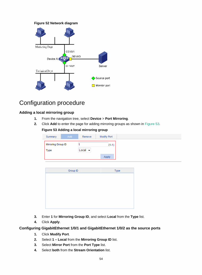
54
Figure 52 Network diagram
Configuration procedure Adding a local mirroring group
1. From the navigation tree, select Device > Port Mirroring. 2. Click Add to enter the page for adding mirroring groups as shown in Figure 53.
Figure 53 Adding a local mirroring group
3. Enter 1 for Mirroring Group ID, and select Local from the Type list. 4. Click Apply.
Configuring GigabitEthernet 1/0/1 and GigabitEthernet 1/0/2 as the source ports 1. Click Modify Port. 2. Select 1 – Local from the Mirroring Group ID list. 3. Select Mirror Port from the Port Type list. 4. Select both from the Stream Orientation list.

55
5. Select 1 (GigabitEthernet 1/0/1) and 2 (GigabitEthernet 1/0/2) on the chassis front panel.
Figure 54 Configuring the source ports
6. Click Apply. A configuration progress dialog box appears.
7. After the success notification appears, click Close.
Configuring GigabitEthernet 1/0/3 as the monitor port 1. Click Modify Port. 2. Select 1 – Local from the Mirroring Group ID list. 3. Select Monitor Port from the Port Type list. 4. Select 3 (GigabitEthernet 1/0/3) on the chassis front panel.
Figure 55 Configuring the monitor port

56
5. Click Apply. A configuration progress dialog box appears.
6. After the success notification appears, click Close.

57
Managing users The user management function allows you to do the following: • Adding a local user, and specifying the password, access level, and service types for the user. • Setting the super password for non-management level users to switch to the management
level. • Switching to the management level from a lower level.
Adding a local user 1. Select Device > Users from the navigation tree. 2. Click the Create tab.
Figure 56 Adding a local user
3. Configure a local user as described in Table 16. 4. Click Apply.
Table 16 Configuration items
Item Description Username Enter a username for the user.
Access Level
Select an access level for the user. Users of different levels can perform different operations. User levels, in order from low to high, are as follows: • Visitor—A visitor level user can perform only ping and traceroute operations.
They cannot access the data on the device or configure the device. • Monitor—A monitor level user can perform ping and traceroute operations and
access the data on the device, but they cannot configure the device. • Configure—A configure level user can perform ping and traceroute operations,
access data on the device, and configure the device, but they cannot upgrade the software, add/delete/modify users, or back up or restore the configuration file.
• Management—A management level user can perform any operations on the device.
Password Set the password for the user.

58
Item Description Confirm Password Enter the same password again.
Password Encryption
Select the password encryption type: • Reversible—Uses a reversible encryption algorithm. The ciphertext password
can be decrypted to get the plaintext password. • Irreversible—Uses an irreversible encryption algorithm. The ciphertext
password cannot be decrypted to get the plaintext password.
Service Type Select the service types for the user to use, including Web and FTP. You must select at least one service type. The device does not support Telnet. The Telnet configuration does not take effect.
Setting the super password A management level user can set the password for non-management level users to switch to the management level. If the password is not set, non-management level users cannot switch to the management level from a lower level.
To set the super password: 1. Select Device > Users from the navigation tree. 2. Click the Super Password tab.
Figure 57 Setting the super password
3. Configure a super password as described in Table 17. 4. Click Apply.
Table 17 Configuration items
Item Description
Create/Remove Select the operation type: • Create—Configure or change the super password. • Remove—Remove the current super password.
Password Set the password for non-management level users to switch to the management level.
Confirm Password Enter the same password again.

59
Item Description
Password Encryption
Select the password encryption type: • Reversible—Uses a reversible encryption algorithm. The ciphertext password
can be decrypted to get the plaintext password. • Irreversible—Uses an irreversible encryption algorithm. The ciphertext
password cannot be decrypted to get the plaintext password.
Switching to the management level A non-management level user can switch to the management level after providing the correct super password.
The level switching operation does not change the access level setting for the user. When the user logs in to the Web interface again, the access level of the user is still the level set for the user.
To switch to the management level: 1. Select Device > Users from the navigation tree. 2. Click the Switch To Management tab. 3. Enter the correct super password. 4. Click Login.
Figure 58 Switching to the management level

60
Configuring a loopback test You can check whether an Ethernet port operates correctly by performing Ethernet port loopback test. During the test time, the port cannot forward data packets correctly.
Ethernet port loopback test has the following types: • Internal loopback test—Establishes self loop in the switching chip and checks whether there
is a chip failure related to the functions of the port. • External loopback test—Uses a loopback plug on the port. Packets forwarded by the port will
be received by itself through the loopback plug. The external loopback test can be used to check whether there is a hardware failure on the port.
Configuration guidelines When you configure a loopback test, follow these restrictions and guidelines: • When a port is physically down, you cannot perform an external loopback test on the port. • After a port is shut down manually, you can perform neither internal nor external test on the port. • When a port is under loopback test, you cannot apply Rate, Duplex, Cable Type, and Port
Status configuration to the port. • An Ethernet port operates in full duplex mode when a loopback test is performed. It restores its
original duplex mode after the loopback test is finished.
Configuration procedure 1. From the navigation tree, select Device > Loopback.
Figure 59 Loopback test page
2. Select External or Internal for loopback test type. 3. Select an Ethernet port from the chassis front panel. 4. Click Test.
After the test is complete, the system displays the loopback test result.

61
Figure 60 Loopback test result

62
Configuring VCT
Overview You can use the Virtual Cable Test (VCT) function to check the status of the cable connected to an Ethernet port on the device. The result is returned in less than 5 seconds. The test covers whether short circuit or open circuit occurs on the cable and the length of the faulty cable.
Testing cable status 1. Select Device > VCT from the navigation tree to enter the page for testing cable status. 2. Select the port you want to test on the chassis front panel. 3. Click Test.
The test result is returned within 5 seconds and displayed in the Result field.
Figure 61 Testing the status of the cable connected to an Ethernet port
The result displays the cable status and length. The cable status can be normal, abnormal, abnormal (open), abnormal (short), or failure.
When a cable is normal, the cable length displayed is the total length of the cable. When a cable is abnormal, the cable length displayed is the length between the current port
and the location where fault occurs. The cable length detected can have an error of up to 5 meters.

63
Configuring the flow interval With the flow interval module, you can view the number of packets and bytes sent and received by a port, and the bandwidth use of the port over the specified interval.
Viewing port traffic statistics 1. Select Device > Flow interval from the navigation tree.
By default, the Port Traffic Statistics tab is displayed. 2. View the number of packets and bytes sent and received by each port, and the bandwidth use
of each port over the last interval.
Figure 62 Port traffic statistics
When the bandwidth utilization is lower than 1%, 1% is displayed.

64
Configuring energy saving Energy saving enables a port to operate at the lowest transmission speed, disable PoE, or go down during a specific time range on certain days of a week. The port resumes when the effective time period ends.
Configuring energy saving on a port 1. Select Device > Energy Saving from the navigation tree to enter the energy saving
configuration page. 2. Click a port.
Figure 63 Energy saving configuration page
3. Configure an energy saving policy for the port as described in Table 18. 4. Click Apply.
Table 18 Configuration items
Item Description Time Range Set the time period when the port is in the state of energy saving.
IMPORTANT: • Up to five energy saving policies with different time ranges can be configured
on a port. • Specify the start time and end time in units of 5 minutes, such as 08:05 to
10:15. Otherwise, the start time is postponed and the end time is brought forward so that they meet the requirements. For example, if you set the time range to 08:08 to 10:12, the effective time range is 08:10 to 10:10.
Sun through Sat
PoE Disabled Disable PoE on the port.
Lowest Speed Set the port to transmit data at the lowest speed. If you configure the lowest speed limit on a port that does not support 10 Mbps, the configuration cannot take effect.

65
Item Description
Shutdown Shut down the port. An energy saving policy can have all the three energy saving schemes configured, of which the shutdown scheme takes the highest priority.

66
Configuring SNMP This chapter provides an overview of the Simple Network Management Protocol (SNMP) and guides you through the configuration procedure.
Overview SNMP is an Internet standard protocol widely used for a management station to access and operate the devices on a network, regardless of their vendors, physical characteristics and interconnect technologies.
SNMP enables network administrators to read and set the variables on managed devices for state monitoring, troubleshooting, statistics collection, and other management purposes.
SNMP mechanism The SNMP framework comprises the following elements: • SNMP manager—Works on an NMS to monitor and manage the SNMP-capable devices in the
network. • SNMP agent—Works on a managed device to receive and handle requests from the NMS, and
send traps to the NMS when some events, such as interface state change, occur. • Management Information Base (MIB)—Specifies the variables (for example, interface status
and CPU usage) maintained by the SNMP agent for the SNMP manager to read and set.
Figure 64 Relationship between an NMS, agent and MIB
A MIB stores variables called "nodes" or "objects" in a tree hierarchy and identifies each node with a unique OID. An OID is a string of numbers that describes the path from the root node to a leaf node. For example, the object B in Figure 65 is uniquely identified by the OID {1.2.1.1}.
Figure 65 MIB tree
SNMP provides the following basic operations: • Get—The NMS retrieves SNMP object nodes in an agent MIB. • Set—The NMS modifies the value of an object node in an agent MIB.

67
• Notifications—Includes traps and informs. SNMP agent sends traps or informs to report events to the NMS. The difference between these two types of notification is that informs require acknowledgement but traps do not. The device supports only traps.
SNMP protocol versions Hewlett Packard Enterprise supports SNMPv1, SNMPv2c, and SNMPv3. An NMS and an SNMP agent must use the same SNMP version to communicate with each other. • SNMPv1—Uses community names for authentication. To access an SNMP agent, an NMS
must use the same community name as set on the SNMP agent. If the community name used by the NMS is different from the community name set on the agent, the NMS cannot establish an SNMP session to access the agent or receive traps and notifications from the agent.
• SNMPv2c—Uses community names for authentication. SNMPv2c is compatible with SNMPv1, but supports more operation modes, data types, and error codes.
• SNMPv3—Uses a user-based security model (USM) to secure SNMP communication. You can configure authentication and privacy mechanisms to authenticate and encrypt SNMP packets for integrity, authenticity, and confidentiality.
Recommended configuration procedure SNMPv3 differs from SNMPv1 and SNMPv2c in many ways. Their configuration procedures are described in separate sections.
Table 19 SNMPv1 or SNMPv2c configuration task list
Task Remarks
1. Enabling SNMP agent
Required. The SNMP agent function is disabled by default.
IMPORTANT: If SNMP agent is disabled, all SNMP agent-related configurations are removed.
2. Configuring an SNMP view
Optional. After creating SNMP views, you can specify an SNMP view for an SNMP community to limit the MIB objects that can be accessed by the SNMP community.
3. Configuring an SNMP community Required.
4. Configuring SNMP trap function
Optional. Allows you to configure that the agent can send SNMP traps to the NMS, and configure information about the target host (usually the NMS) of the SNMP traps. The SNMP agent sends traps to inform the NMS of important events, such as a reboot. By default, an agent is allowed to send SNMP traps to the NMS.
5. Displaying SNMP packet statistics Optional.

68
Table 20 SNMPv3 configuration task list
Task Remarks
1. Enabling SNMP agent
Required. The SNMP agent function is disabled by default.
IMPORTANT: If SNMP agent is disabled, all SNMP agent-related configurations are removed.
2. Configuring an SNMP view
Optional. After creating SNMP views, you can specify an SNMP view for an SNMP group to limit the MIB objects that can be accessed by the SNMP group.
3. Configuring an SNMP group
Required. After creating an SNMP group, you can add SNMP users to the group when creating the users. Therefore, you can realize centralized management of users in the group through the management of the group.
4. Configuring an SNMP user
Required. Before creating an SNMP user, you need to create the SNMP group to which the user belongs.
IMPORTANT: After you change the local engine ID, the existing SNMPv3 users become invalid, and you must re-create the SNMPv3 users. For more information about engine ID, see "Enabling SNMP agent."
5. Configuring SNMP trap function
Optional. Allows you to configure that the agent can send SNMP traps to the NMS, and configure information about the target host (usually the NMS) of the SNMP traps. The SNMP agent sends traps to inform the NMS of important events, such as a reboot. By default, an agent is allowed to send SNMP traps to the NMS.
6. Displaying SNMP packet statistics Optional.
Enabling SNMP agent 1. Select Device > SNMP from the navigation tree.
The SNMP configuration page appears.

69
Figure 66 Setup tab
2. Configure SNMP settings on the upper part of the page as described in Table 21. 3. Click Apply.
Table 21 Configuration items
Item Description SNMP Specify to enable or disable SNMP agent.
Local Engine ID
Configure the local engine ID. The validity of a user after it is created depends on the engine ID of the SNMP agent. If the engine ID when the user is created is not identical to the current engine ID, the user is invalid.
Maximum Packet Size Configure the maximum size of an SNMP packet that the agent can receive or send.
Contact
Set a character string to describe contact information for system maintenance. If the device is faulty, the maintainer can contact the manufacture factory according to the contact information of the device.
Location Set a character string to describe the physical location of the device.
SNMP Version Set the SNMP version run by the system.

70
Configuring an SNMP view Creating an SNMP view
1. Select Device > SNMP from the navigation tree. 2. Click the View tab.
The View tab appears.
Figure 67 View tab
3. Click Add. The Add View window appears.
Figure 68 Creating an SNMP view (1)
4. Type the view name. 5. Click Apply.
The page in Figure 69 appears. 6. Configure the parameters as described in Table 22. 7. Click Add to add the rule into the list box at the lower part of the page. 8. Repeat steps 6 and 7 to add more rules for the SNMP view. 9. Click Apply.
To cancel the view, click Cancel.

71
Figure 69 Creating an SNMP view (2)
Table 22 Configuration items
Item Description View Name Set the SNMP view name.
Rule Select to exclude or include the objects in the view range determined by the MIB subtree OID and subtree mask.
MIB Subtree OID Set the MIB subtree OID (such as 1.4.5.3.1) or name (such as system). MIB subtree OID identifies the position of a node in the MIB tree, and it can uniquely identify a MIB subtree.
Subtree Mask
Set the subtree mask, a hexadecimal string. Its length must be an even number in the range of 2 to 32. If no subtree mask is specified, the default subtree mask (all Fs) will be used for mask-OID matching.
Adding rules to an SNMP view 1. Select Device > SNMP from the navigation tree. 2. Click the View tab.
The page in Figure 67 appears.
3. Click the icon of the target view. The Add rule for the view ViewDefault window appears.

72
Figure 70 Adding rules to an SNMP view
4. Configure the parameters as described in Table 22. 5. Click Apply.
NOTE: You can also click the icon corresponding to the specified view on the page as shown in Figure 67, and then you can enter the page to modify the view.
Configuring an SNMP community 1. Select Device > SNMP from the navigation tree. 2. Click the Community tab.
The Community tab appears.
Figure 71 Configuring an SNMP community
3. Click Add. The Add SNMP Community page appears.

73
Figure 72 Creating an SNMP Community
4. Configure the SNMP community as described in Table 23. 5. Click Apply.
Table 23 Configuration items
Item Description Community Name Set the SNMP community name.
Access Right
Configure SNMP NMS access right: • Read only—The NMS can perform read-only operations to the MIB
objects when it uses this community name to access the agent. • Read and write—The NMS can perform both read and write
operations to the MIB objects when it uses this community name to access the agent.
View Specify the view associated with the community to limit the MIB objects that can be accessed by the NMS.
ACL Associate the community with a basic ACL to allow or prohibit the access to the agent from the NMS with the specified source IP address. ACL settings are reserved for future use.
Configuring an SNMP group 1. Select Device > SNMP from the navigation tree. 2. Click the Group tab.
The Group tab appears.
Figure 73 SNMP group
3. Click Add.

74
The Add SNMP Group page appears.
Figure 74 Creating an SNMP group
4. Configure SNMP group as described in Table 24. 5. Click Apply.
Table 24 Configuration items
Item Description Group Name Set the SNMP group name.
Security Level
Select the security level for the SNMP group: • NoAuth/NoPriv—No authentication no privacy. • Auth/NoPriv—Authentication without privacy. • Auth/Priv—Authentication and privacy.
IMPORTANT: For an existing SNMP group, its security level cannot be modified.
Read View Select the read view of the SNMP group.
Write View Select the write view of the SNMP group. If no write view is configured, the NMS cannot perform the write operations to all MIB objects on the device.
Notify View Select the notify view (the view that can send trap messages) of the SNMP group.If no notify view is configured, the agent does not send traps to the NMS.
ACL
Associate a basic ACL with the group to restrict the source IP address of SNMP packets. To restrict the intercommunication between the NMS and the agent, you can allow or prohibit SNMP packets with a specific source IP address. ACL settings are reserved for future use.
Configuring an SNMP user 1. Select Device > SNMP from the navigation tree. 2. Click the User tab.
The User tab appears.

75
Figure 75 SNMP user
3. Click Add. The Add SNMP User page appears.
Figure 76 Creating an SNMP user
4. Configure the SNMP user as described in Table 25. 5. Click Apply.
Table 25 Configuration items
Item Description User Name Set the SNMP user name.
Security Level
Select the security level for the SNMP group. The available security levels are: • NoAuth/NoPriv—No authentication no privacy. • Auth/NoPriv—Authentication without privacy. • Auth/Priv—Authentication and privacy.

76
Item Description
Group Name
Select an SNMP group to which the user belongs: • When the security level is NoAuth/NoPriv, you can select an
SNMP group with no authentication no privacy. • When the security level is Auth/NoPriv, you can select an
SNMP group with no authentication no privacy or authentication without privacy.
• When the security level is Auth/Priv, you can select an SNMP group of any security level.
Authentication Mode Select an authentication mode (including MD5 and SHA) when the security level is Auth/NoPriv or Auth/Priv.
Authentication Password Set the authentication password when the security level is Auth/NoPriv or Auth/Priv. The confirm authentication password must be the same with the authentication password.
Confirm Authentication Password
Privacy Mode Select a privacy mode (including DES56, AES128, and 3DES) when the security level is Auth/Priv.
Privacy Password Set the privacy password when the security level is Auth/Priv. The confirm privacy password must be the same with the privacy password. Confirm Privacy Password
ACL
Associate a basic ACL with the user to restrict the source IP address of SNMP packets. To allow or prohibit the specified NMS to access the agent by using this user name, you can allow or prohibit SNMP packets with a specific source IP address. ACL settings are reserved for future use.
Configuring SNMP trap function 1. Select Device > SNMP from the navigation tree. 2. Click the Trap tab.
The Trap tab appears.
Figure 77 Traps configuration
3. Select Enable SNMP Trap.

77
4. Click Apply to enable the SNMP trap function. 5. Click Add.
The page for adding a target host of SNMP traps appears.
Figure 78 Adding a target host of SNMP traps
6. Configure the settings for the target host as described in Table 26. 7. Click Apply.
Table 26 Configuration items
Item Description
Destination IP Address
Set the destination IP address. Select the IP address type: IPv4 or IPv6, and then type the corresponding IP address in the field according to the IP address type.
Security Name Set the security name, which can be an SNMPv1 community name, an SNMPv2c community name, or an SNMPv3 user name.
UDP Port
Set UDP port number.
IMPORTANT: The default port number is 162, which is the SNMP-specified port used for receiving traps on the NMS. Generally (such as using IMC or MIB Browser as the NMS), you can use the default port number. To change this parameter to another value, you need to make sure the configuration is the same with that on the NMS.
Security Model Select the security model, for which you must set the SNMP version. For the NMS to receive notifications, make sure the SNMP version is the same with that on the NMS.
Security Level
Set the authentication and privacy mode for SNMP traps when the security model is selected as v3. The available security levels are: no authentication no privacy, authentication but no privacy, and authentication and privacy. When the security model is selected as v1 or v2c, the security level is no authentication no privacy, and cannot be modified.

78
Displaying SNMP packet statistics Select Device > SNMP from the navigation tree.
The page for displaying SNMP packet statistics appears.
Figure 79 SNMP packet statistics
SNMPv1/v2c configuration example Network requirements
As shown in Figure 80, the NMS at 1.1.1.2/24 uses SNMPv1 or SNMPv2c to manage the switch (agent) at 1.1.1.1/24, and the switch automatically sends traps to report events to the NMS.
Figure 80 Network diagram
Configuring the agent 1. Enable SNMP:
a. Select Device > SNMP from the navigation tree. The SNMP configuration page appears.
b. Select the Enable option, and select the v1 and v2c options. c. Click Apply.

79
Figure 81 Configuring the SNMP agent
2. Configure a read-only community: a. Click the Community tab. b. Click Add.
The Add SNMP Community page appears. c. Enter public in the Community Name field, and select Read only from the Access Right
list. d. Click Apply.
Figure 82 Configuring an SNMP read-only community
3. Configure a read and write community: a. Click Add on the Community tab page.
The Add SNMP Community page appears. b. Enter private in the Community Name field, and select Read and write from the Access
Right list. c. Click Apply.

80
Figure 83 Configuring an SNMP read and write community
4. Enable SNMP traps: a. Click the Trap tab.
The Trap tab page appears. b. Select Enable SNMP Trap. c. Click Apply.
Figure 84 Enabling SNMP traps
5. Configure a target host SNMP traps: a. Click Add on the Trap tab page.
The page for adding a target host of SNMP traps appears. b. Select the IPv4/Domain option and type 1.1.1.2 in the following field, type public in the
Security Name field, and select v1 from the Security Model list. c. Click Apply.

81
Figure 85 Adding a trap target host
Configuring the NMS The configuration on the NMS must be consistent with that on the agent. Otherwise, you cannot perform corresponding operations.
To configure the NMS: 1. Configure the SNMP version for the NMS as v1 or v2c. 2. Create a read-only community and name it public. 3. Create a read and write community and name it private.
For information about how to configure the NMS, see the NMS manual.
Verifying the configuration After the above configuration, an SNMP connection is established between the NMS and the agent. The NMS can get and configure the values of some parameters on the agent through MIB nodes.
Disable or enable an idle interface on the agent, and you can see the interface state change traps on the NMS.
SNMPv3 configuration example Network requirements
As shown in Figure 86, the NMS (1.1.1.2/24) uses SNMPv3 to monitor and manage the interface status of the AP (the agent) at 1.1.1.1/24, and the AP automatically sends traps to report events to the NMS.
The NMS and the agent perform authentication when they set up an SNMP session. The authentication algorithm is MD5 and the authentication key is authkey. The NMS and the AP also encrypt the SNMP packets between them by using the DES56 algorithm and the privacy key prikey.
Figure 86 Network diagram

82
Configuring the agent 1. Enable SNMP agent:
a. Select Device > SNMP from the navigation tree. The SNMP configuration page appears.
b. Select the Enable option, and select the v3 option. c. Click Apply.
Figure 87 Configuring the SNMP agent
2. Configure an SNMP view: a. Click the View tab. b. Click Add.
The page for creating an SNMP view appears. c. Type view1 in the View Name field. d. Click Apply.
Figure 88 Creating an SNMP view (1)
e. On the page that appears, select the Included option, type the MIB subtree OID interfaces, and click Add.
f. Click Apply. A configuration progress dialog box appears.
g. Click Close after the configuration process is complete.

83
Figure 89 Creating an SNMP view (2)
3. Configure an SNMP group: a. Click the Group tab. b. Click Add.
The page in Figure 90 appears. c. Type group1 in the Group Name field, select view1 from the Read View list, select view1
from the Write View list. d. Click Apply.
Figure 90 Creating an SNMP group
4. Configure an SNMP user: a. Click the User tab. b. Click Add.
The page in Figure 91 appears. c. Type user1 in the User Name field, select Auth/Priv from the Security Level list, select
group1 from the Group Name list, select MD5 from the Authentication Mode list, type authkey in the Authentication Password and Confirm Authentication Password fields, select DES56 from the Privacy Mode list, and type prikey in the Privacy Password and Confirm Privacy Password fields.

84
d. Click Apply.
Figure 91 Creating an SNMP user
5. Enable SNMP traps: a. Click the Trap tab.
The Trap tab page appears. b. Select Enable SNMP Trap. c. Click Apply.
Figure 92 Enabling SNMP traps
6. Configure a target host SNMP traps: a. Click Add on the Trap tab page.
The page for adding a target host of SNMP traps appears.

85
b. Select the IPv4/Domain option and type 1.1.1.2 in the following field, type user1 in the Security Name field, select v3 from the Security Model list, and select Auth/Priv from the Security Level list.
c. Click Apply.
Figure 93 Adding a trap target host
Configuring the NMS The configuration on NMS must be consistent with that on the agent. Otherwise, you cannot perform corresponding operations.
To configure the NMS: 1. Specify the SNMP version for the NMS as v3. 2. Create an SNMP user user1. 3. Enable both authentication and privacy functions 4. Use MD5 for authentication and DES56 for encryption. 5. Set the authentication key to authkey and the privacy key to prikey.
For information about configuring the NMS, see the NMS manual.
Verifying the configuration After the above configuration, the NMS can establish an SNMP connection with the agent and query and reconfigure values of objects in the agent MIB.
Disable or enable an idle interface on the agent, and you can see the interface state change traps on the NMS.

86
Displaying interface statistics The interface statistics module displays statistics about the packets received and sent through interfaces.
To display interface statistics, select Device > Interface Statistics from the navigation tree.
Figure 94 Interface statistics display page
Table 27 describes the fields on the page.
Table 27 Field description
Field Description InOctets Total octets of all packets received on the interface.
InUcastPkts Number of received unicast packets.
InNUcastPkts Number of received non-unicast packets.
InDiscards Number of valid packets discarded in the inbound direction.
InErrors Number of received invalid packets.
InUnknownProtos Number of received unknown protocol packets.
OutOctets Total octets of all packets sent through the interface.
OutUcastPkts Number of unicast packets sent through the interface.
OutNUcastPkts Number of non-unicast packets sent through the interface.
OutDiscards Number of valid packets discarded in the outbound direction.
OutErrors Number of invalid packets sent through the interface.
Last statistics clearing time Last time when the statistics were cleared.

87
Configuring VLANs
Overview Ethernet is a network technology based on the CSMA/CD mechanism. As the medium is shared, collisions and excessive broadcasts are common on an Ethernet. To address the issue, virtual LAN (VLAN) was introduced to break a LAN down into separate VLANs. VLANs are isolated from each other at Layer 2. A VLAN is a bridging domain, and all broadcast traffic is contained within it, as shown in Figure 95.
Figure 95 A VLAN diagram
A VLAN is logically divided on an organizational basis rather than on a physical basis. For example, all workstations and servers used by a particular workgroup can be assigned to the same VLAN, regardless of their physical locations.
VLAN technology delivers the following benefits: • Confining broadcast traffic within individual VLANs. This reduces bandwidth waste and
improves network performance. • Improving LAN security. By assigning user groups to different VLANs, you can isolate them at
Layer 2. To enable communication between VLANs, routers or Layer 3 switches are required. • Flexible virtual workgroup creation. As users from the same workgroup can be assigned to the
same VLAN regardless of their physical locations, network construction and maintenance is much easier and more flexible.
VLAN fundamentals To enable a network device to identify frames of different VLANs, a VLAN tag field is inserted into the data link layer encapsulation. The format of VLAN-tagged frames is defined in IEEE 802.1Q-1999.
In the header of a traditional Ethernet data frame, the field after the destination MAC address and the source MAC address is the Type field indicating the upper layer protocol type, as shown in Figure 96.
Figure 96 Traditional Ethernet frame format
IEEE 802.1Q inserts a four-byte VLAN tag after the DA&SA field, as shown in Figure 97.

88
Figure 97 Position and format of VLAN tag
A VLAN tag comprises the following fields: • Tag protocol identifier (TPID)—The 16-bit TPID field indicates whether the frame is
VLAN-tagged and is 0x8100 by default. • Priority—The 3-bit priority field indicates the 802.1p priority of the frame. • Canonical format indicator (CFI)—The 1-bit CFI field specifies whether the MAC addresses
are encapsulated in the standard format when packets are transmitted across different media. A value of 0 indicates that MAC addresses are encapsulated in the standard format. The value of 1 indicates that MAC addresses are encapsulated in a non-standard format. The value of the field is 0 by default.
• VLAN ID—The 12-bit VLAN ID field identifies the VLAN the frame belongs to. The VLAN ID range is 0 to 4095. As 0 and 4095 are reserved, a VLAN ID actually ranges from 1 to 4094.
A network device handles an incoming frame depending on whether the frame is VLAN tagged and the value of the VLAN tag, if any.
The Ethernet II encapsulation format is used in this section. In addition to the Ethernet II encapsulation format, Ethernet also supports other encapsulation formats, including 802.2 LLC, 802.2 SNAP, and 802.3 raw. The VLAN tag fields are added to frames encapsulated in these formats for VLAN identification.
When a frame carrying multiple VLAN tags passes through, the device processes the frame according to its outer VLAN tag, and transmits the inner tags as payload.
VLAN types You can implement VLANs based on the following criteria: • Port. • MAC address. • Protocol. • IP subnet. • Policy. • Other criteria.
The Web interface is available only for port-based VLANs, and this chapter introduces only port-based VLANs.
Port-based VLAN Port-based VLANs group VLAN members by port. A port forwards traffic for a VLAN only after it is assigned to the VLAN.
Port link type You can configure the link type of a port as access, trunk, or hybrid. The link types use the following VLAN tag handling methods:
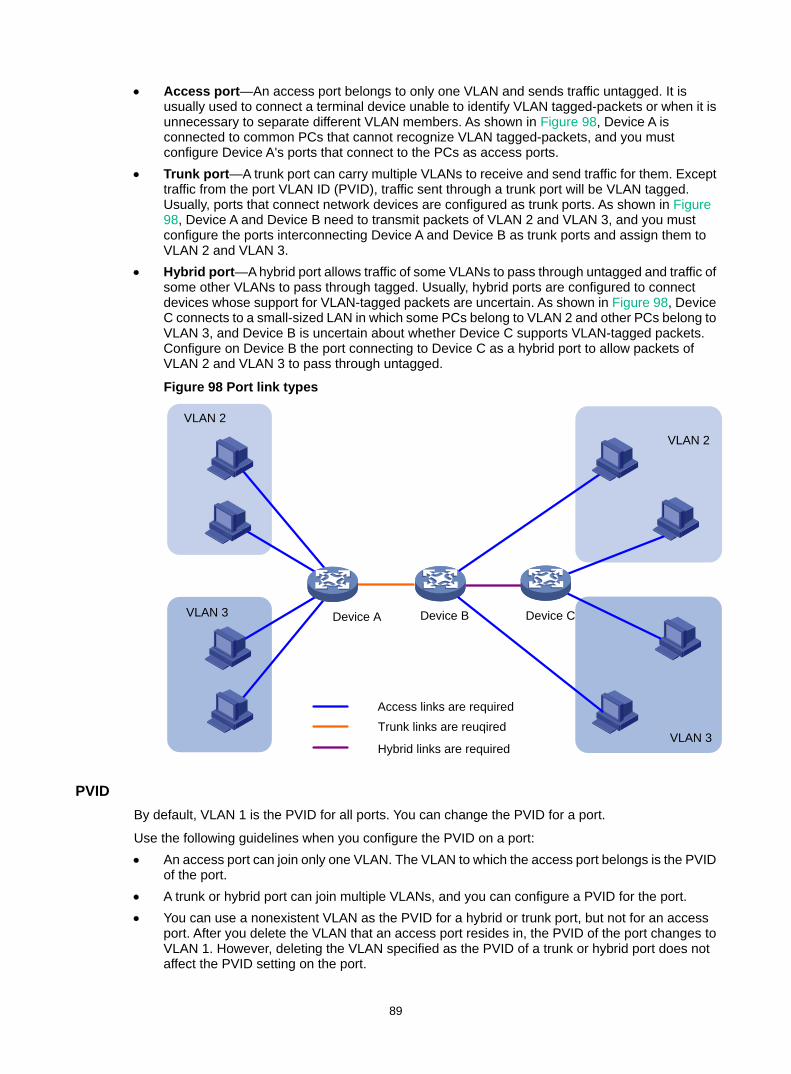
89
• Access port—An access port belongs to only one VLAN and sends traffic untagged. It is usually used to connect a terminal device unable to identify VLAN tagged-packets or when it is unnecessary to separate different VLAN members. As shown in Figure 98, Device A is connected to common PCs that cannot recognize VLAN tagged-packets, and you must configure Device A's ports that connect to the PCs as access ports.
• Trunk port—A trunk port can carry multiple VLANs to receive and send traffic for them. Except traffic from the port VLAN ID (PVID), traffic sent through a trunk port will be VLAN tagged. Usually, ports that connect network devices are configured as trunk ports. As shown in Figure 98, Device A and Device B need to transmit packets of VLAN 2 and VLAN 3, and you must configure the ports interconnecting Device A and Device B as trunk ports and assign them to VLAN 2 and VLAN 3.
• Hybrid port—A hybrid port allows traffic of some VLANs to pass through untagged and traffic of some other VLANs to pass through tagged. Usually, hybrid ports are configured to connect devices whose support for VLAN-tagged packets are uncertain. As shown in Figure 98, Device C connects to a small-sized LAN in which some PCs belong to VLAN 2 and other PCs belong to VLAN 3, and Device B is uncertain about whether Device C supports VLAN-tagged packets. Configure on Device B the port connecting to Device C as a hybrid port to allow packets of VLAN 2 and VLAN 3 to pass through untagged.
Figure 98 Port link types
PVID By default, VLAN 1 is the PVID for all ports. You can change the PVID for a port.
Use the following guidelines when you configure the PVID on a port: • An access port can join only one VLAN. The VLAN to which the access port belongs is the PVID
of the port. • A trunk or hybrid port can join multiple VLANs, and you can configure a PVID for the port. • You can use a nonexistent VLAN as the PVID for a hybrid or trunk port, but not for an access
port. After you delete the VLAN that an access port resides in, the PVID of the port changes to VLAN 1. However, deleting the VLAN specified as the PVID of a trunk or hybrid port does not affect the PVID setting on the port.
VLAN 2
VLAN 3
VLAN 2
VLAN 3
Access links are requiredTrunk links are reuqired
Hybrid links are required
Device A Device B Device C

90
• Hewlett Packard Enterprise recommends that you set the same PVID for local and remote ports.
• Make sure a port permits its PVID. Otherwise, when the port receives frames tagged with the PVID or untagged frames, the port drops these frames.
Frame handling methods The following table shows how ports of different link types handle frames:
Actions Access Trunk Hybrid In the inbound direction for an untagged frame
Tags the frame with the PVID tag.
Checks whether the PVID is permitted on the port: • If yes, tags the frame with the PVID tag. • If not, drops the frame.
In the inbound direction for a tagged frame
• Receives the frame if its VLAN ID is the same as the PVID.
• Drops the frame if its VLAN ID is different from the PVID.
• Receives the frame if its VLAN is permitted on the port. • Drops the frame if its VLAN is not permitted on the port.
In the outbound direction
Removes the VLAN tag and sends the frame.
• Removes the tag and sends the frame if the frame carries the PVID tag and the port belongs to the PVID.
• Sends the frame without removing the tag if its VLAN is carried on the port, but is different from the PVID.
Sends the frame if its VLAN is permitted on the port. The frame is sent with the VLAN tag removed or intact depending on your configuration with the port hybrid vlan command. This is true of the PVID.
Recommended VLAN configuration procedures Recommended configuration procedure for assigning an access port to a VLAN
Step Remarks
1. Creating VLANs. Required. Create one or multiple VLANs.
2. Configuring the link type of a port. Optional. Configure the link type of the port as access. By default, the link type of a port is access.

91
Step Remarks
3. Setting the PVID for a port. Configure the PVID of the access port.
Required. An access port has only one untagged VLAN and the untagged VLAN is its PVID. The three operations produce the same result, and the latest operation takes effect. By default, an access port is an untagged member of VLAN 1.
4. Configuring the access ports as untagged members of a VLAN: a. Selecting VLANs
Specify the range of VLANs available for selection during related operations. Configure a subset of all existing VLANs. This step is required before you perform operations on the Detail, Modify VLAN, and Modify Port tabs.
b. Modifying a VLAN Configure the access ports as untagged members of the specified VLAN.
N/A
5. Modifying ports. Configure the untagged VLAN of the port.
Recommended configuration procedure for assigning a trunk port to a VLAN
Step Remarks
1. Creating VLANs. Required. Create one or multiple VLANs.
2. Configuring the link type of a port.
Optional. Configure the link type of the port as trunk. To configure a hybrid port as a trunk port, first configure it as an access port. By default, the link type of a port is access.
3. Setting the PVID for a port. Configure the PVID of the trunk port. Required.
A trunk port has only one untagged VLAN and the untagged VLAN is its PVID. The three operations produce the same result, and the latest operation takes effect. By default, the untagged VLAN of a trunk port is VLAN 1. When you change the untagged VLAN (PVID) of a trunk port, the former untagged VLAN automatically becomes a tagged VLAN of the trunk port.
4. Configure the trunk port as an untagged member of the specified VLANs: a. Selecting VLANs
Specify the range of VLANs available for selection during related operations. Configure a subset of all existing VLANs. This step is required before you perform operations on the Detail, Modify VLAN, and Modify Port tabs.
b. Modifying a VLAN Configure the trunk port as an untagged member of the specified VLANs.
N/A
5. Modifying ports. Configure the untagged VLAN of the trunk port.

92
Step Remarks 6. Configure the trunk port as a tagged
member of the specified VLANs: a. Selecting VLANs
Specify the range of VLANs available for selection during related operations. Configure a subset of all existing VLANs. This step is required before you perform operations on the Detail, Modify VLAN, and Modify Port tabs.
b. Modifying a VLAN Configure the trunk port as a tagged member of the specified VLANs.
N/A Required. A trunk port can have multiple tagged VLANs. You can repeat these steps to configure multiple tagged VLANs for the trunk port.
7. Modifying ports. Configure the tagged VLAN of the trunk port.
Recommended configuration procedure for assigning a hybrid port to a VLAN
Step Remarks
1. Creating VLANs. Required. Create one or multiple VLANs.
2. Configuring the link type of a port.
Optional. Configure the link type of the port as hybrid. To configure a trunk port as a hybrid port, first configure it as an access port. If you configure multiple untagged VLANs for a trunk port at the same time, the trunk port automatically becomes a hybrid port. By default, the link type of a port is access.
3. Setting the PVID for a port. Optional. Configure the PVID of the hybrid port. By default, the PVID of a hybrid port is VLAN 1.

93
Step Remarks 4. Configure the hybrid port as an untagged
member of the specified VLANs: a. Selecting VLANs
Specify the range of VLANs available for selection during related operations. Configure a subset of all existing VLANs. This step is required before you perform operations on the Detail, Modify VLAN, and Modify Port tabs.
b. Modifying a VLAN Configure the hybrid port as an untagged member of the specified VLAN.
N/A
Required. A hybrid port can have multiple untagged VLANs. Repeat these steps to configure multiple untagged VLANs for a hybrid port. By default, the untagged VLAN of a hybrid port is VLAN 1.
5. Modifying ports. Configure the untagged VLAN of the hybrid port.
6. Configure the hybrid port as a tagged member of the specified VLAN: a. Selecting VLANs
Specify the range of VLANs available for selection during related operations. Configure a subset of all existing VLANs. This step is required before you perform operations on the Detail, Modify VLAN, and Modify Port tabs.
b. Modifying a VLAN Configure the hybrid port as a tagged member of the specified VLAN.
N/A Required. A hybrid port can have multiple tagged VLANs. You can repeat these steps to configure multiple tagged VLANs for the hybrid port.
7. Modifying ports. Configure the tagged VLAN of the hybrid port.
Creating VLANs 1. From the navigation tree, select Network > VLAN. 2. Click Create to enter the page for creating VLANs. 3. Enter the VLAN IDs, a VLAN ID range, or both. 4. Click Create.

94
Figure 99 Creating VLANs
Table 28 Configuration items
Item Description VLAN IDs IDs of the VLANs to be created.
Modify the description of the selected VLAN
• ID—Select the ID of the VLAN whose description string is to be modified. Click the ID of the VLAN to be modified in the list in the middle of the page.
• Description—Set the description string of the selected VLAN. By default, the description string of a VLAN is its VLAN ID, such as VLAN 0001.
Configuring the link type of a port You can also configure the link type of a port on the Setup tab of Device > Port Management. For more information, see "Managing ports."
To configure the link type of a port: 1. From the navigation tree, select Network > VLAN. 2. Click Modify Port. 3. Select the port that you want to configure on the chassis front panel. 4. Select the Link Type option. 5. Set the link type to access, hybrid, or trunk. 6. Click Apply.
A progress dialog box appears. 7. Click Close on the progress dialog box when the dialog box prompts that the configuration
succeeds.

95
Figure 100 Modifying ports
Setting the PVID for a port You can also configure the PVID of a port on the Setup tab of Device > Port Management. For more information, see "Managing ports."
To set the PVID for a port: 1. From the navigation tree, select Network > VLAN. 2. Click Modify Port. 3. Select the port that you want to configure on the chassis front panel. 4. Select the PVID option.
The option allows you to modify the PVID of the port. 5. Set a PVID for the port. By selecting the Delete box, you can restore the PVID of the port to the
default, which is VLAN 1. The PVID of an access port must be an existing VLAN.
6. Click Apply. A progress dialog box appears.
7. Click Close on the progress dialog box when the dialog box prompts that the configuration succeeds.

96
Figure 101 Modifying the PVID for a port
Selecting VLANs 1. From the navigation tree, select Network > VLAN.
The Select VLAN tab is displayed by default for you to select VLANs.
Figure 102 Selecting VLANs
2. Select the Display all VLANs option to display all VLANs, or select the Display a subnet of all configured VLANs option to enter the VLAN IDs to be displayed.
3. Click Select.

97
Modifying a VLAN 1. From the navigation tree, select Network > VLAN. 2. Click Modify VLAN to enter the page for modifying a VLAN.
Figure 103 Modifying a VLAN
3. Modify the member ports of a VLAN as described in Table 29. 4. Click Apply.
A progress dialog box appears. 5. Click Close on the progress dialog box when the dialog box prompts that the configuration
succeeds.
Table 29 Configuration items
Item Description
Please select a VLAN to modify
Select the VLAN to be modified. The VLANs available for selection are existing VLANs selected on the page for selecting VLANs.
Modify Description Modify the description string of the selected VLAN. By default, the description string of a VLAN is its VLAN ID, such as VLAN 0001.
Select membership type
Set the member type of the port to be modified in the VLAN: • Untagged—Configures the port to send the traffic of the VLAN after removing
the VLAN tag. • Tagged—Configures the port to send the traffic of the VLAN without removing
the VLAN tag. • Not a Member—Removes the port from the VLAN.
Select ports to be modified and assigned to this VLAN
Select the ports to be modified in the selected VLAN. When you configure an access port as a tagged member of a VLAN, the link type of the port is automatically changed into hybrid.

98
Modifying ports 1. From the navigation tree, select Network > VLAN. 2. Click Modify Port to enter the page for modifying ports.
Figure 104 Modifying ports
3. Modify the VLANs of a port as described in Table 30. 4. Click Apply.
A progress dialog box appears. 5. Click Close on the progress dialog box when the dialog box prompts that the configuration
succeeds.
Table 30 Configuration items
Item Description Select Ports Select the ports to be modified.
Select membership type
Set the member types of the selected ports to be modified in the specified VLANs: • Untagged—Configures the ports to send the traffic of the VLANs after removing the
VLAN tags. • Tagged—Configures the ports to send the traffic of the VLANs without removing the
VLAN tags. • Not a Member—Removes the ports from the VLANs.

99
Item Description
VLAN IDs
Set the IDs of the VLANs to or from which the selected ports are to be assigned or removed. When you set the VLAN IDs, follow these guidelines: • You cannot configure an access port as an untagged member of a nonexistent VLAN.• When you configure an access port as a tagged member of a VLAN, or configure a
trunk port as an untagged member of multiple VLANs in bulk, the link type of the port is automatically changed into hybrid.
• You can configure a hybrid port as a tagged or untagged member of a VLAN only if the VLAN is an existing, static VLAN.
VLAN configuration example Network requirements
As shown in Figure 105, trunk port GigabitEthernet 1/0/1 of Switch A is connected to trunk port GigabitEthernet 1/0/1 of Switch B.
Configure the PVID of GigabitEthernet 1/0/1 as VLAN 100, and configure GigabitEthernet 1/0/1 to permit packets from VLAN 2, VLAN 6 through VLAN 50, and VLAN 100 to pass through.
Figure 105 Network diagram
Configuring Switch A 1. Configure GigabitEthernet 1/0/1 as a trunk port and configure VLAN 100 as the PVID:
a. From the navigation tree, select Device > Port Management. b. Click Setup to enter the page for setting ports. c. Select Trunk in the Link Type list, select the PVID box, and then enter PVID 100. d. Select GigabitEthernet 1/0/1 on the chassis front device panel. e. Click Apply.

100
Figure 106 Configuring GigabitEthernet 1/0/1 as a trunk port and its PVID as 100
2. Create VLAN 2, VLAN 6 through VLAN 50, and VLAN 100: a. From the navigation tree, select Network > VLAN. b. Click Create to enter the page for creating VLANs. c. Enter VLAN IDs 2, 6-50, 100. d. Click Apply.

101
Figure 107 Creating VLAN 2, VLAN 6 through VLAN 50, and VLAN 100
3. Assign GigabitEthernet 1/0/1 to VLAN 100 as an untagged member: a. Click Select VLAN to enter the page for selecting VLANs. b. Select the option before Display a subnet of all configured VLANs, and enter 1-100 in
the field. c. Click Select.
Figure 108 Setting a VLAN range
d. Click Modify VLAN to enter the page for modifying the ports in a VLAN. e. Select 100 – VLAN 0100 in the Please select a VLAN to modify: list, select the Untagged
option, and select GigabitEthernet 1/0/1 on the chassis front device panel. f. Click Apply.

102
A configuration progress dialog box appears. g. After the configuration process is complete, click Close.
Figure 109 Assigning GigabitEthernet 1/0/1 to VLAN 100 as an untagged member
4. Assign GigabitEthernet 1/0/1 to VLAN 2, and VLAN 6 through VLAN 50 as a tagged member: a. Click Modify Port to enter the page for modifying the VLANs to which a port belongs. b. Select GigabitEthernet 1/0/1 on the chassis front device panel, select the Tagged option,
and enter VLAN IDs 2, 6-50. c. Click Apply.
A configuration progress dialog box appears. d. After the configuration process is complete, click Close in the dialog box.

103
Figure 110 Assigning GigabitEthernet 1/0/1 to VLAN 2 and to VLANs 6 through 50 as a tagged member
Configuring Switch B Configure Switch B in the same way Switch A is configured. (Details not shown.)
Configuration guidelines When you configure VLANs, follow these restrictions and guidelines: • You cannot create or delete the system default VLAN (VLAN 1). • Dynamic VLANs cannot be deleted on the page for deleting VLANs.

104
Configuring VLAN interfaces Before creating a VLAN interface, you must create the corresponding VLAN in Network > VLAN. For more information, see "Configuring VLANs."
Overview VLAN interfaces are virtual interfaces used for Layer 3 communication between different VLANs. They do not exist as physical entities on devices. For each VLAN, you can create one VLAN interface. You can assign the VLAN interface an IP address, and specify it as the gateway of the VLAN to forward the traffic destined for an IP network segment different from that of the VLAN. As for VLAN interfaces, only VLAN-interface 1 is supported by the switch,and the VLAN-interface cannot be modified.
Creating a VLAN interface When you create a VLAN interface, you can select to assign an IPv4 address and an IPv6 link-local address to the VLAN interface in this step or in a separate step. If you do not select to configure an IP address, you can create the VLAN interface, and configure an IP address for the VLAN interface by modifying it.
To create a VLAN interface: 1. From the navigation tree, select Network > VLAN Interface. 2. Click Create to enter the page for creating a VLAN interface.
Figure 111 Creating a VLAN interface
3. Configure the VLAN interface as described in Table 31. 4. Click Apply.

105
Table 31 Configuration items
Item Description
Input a VLAN ID: Enter the ID of the VLAN interface to be created. Before creating a VLAN interface, make sure the corresponding VLAN exists.
Configure Primary IPv4 Address
DHCP Configure the way in which the VLAN interface gets an IPv4 address. Allow the VLAN interface to get an IP address automatically by selecting the DHCP or BOOTP option. Otherwise, select the Manual option to manually assign the VLAN interface an IP address. After a VLAN interface fails to get an IP address through DHCP multiple times, the device stops IP address application and configures the default IP address for the interface.
These items are available after you select the Configure Primary IPv4 Address box.
BOOTP
Manual
IPv4 Address
Configure an IPv4 address for the VLAN interface. This field is available after you select the Manual option.
Mask Length
Set the subnet mask length (or enter a mask in dotted decimal notation format). This field is available after you select the Manual option.
Configure IPv6 Link Local Address
Auto Configure the way in which the VLAN interface gets an IPv6 link-local address. Select the Auto or Manual option: • Auto—The device automatically assigns a link-local address
to the VLAN interface based on the link-local address prefix (FE80::/64) and the link-layer address of the VLAN interface.
• Manual—Requires manual assignment.
These items are available after you select the Configure IPv6 Link Local Address box.
Manual
IPv6 Address
Configure an IPv6 link-local address for the VLAN interface. This field is available after you select the Manual option. The prefix of the IPv6 link-local address you enter must be FE80::/64.
Modifying a VLAN interface By modifying a VLAN interface, you can assign an IPv4 address, an IPv6 link-local address, and an IPv6 site-local address, or global unicast address to the VLAN interface, and shut down or bring up the VLAN interface.
After you modify the IPv4 address and status or the IPv6 address and status, or add an IPv6 unicast address for a selected VLAN interface on the page for modifying VLAN interfaces, you must click the correct Apply button to submit the modification.
After you change the IP address of the VLAN interface you are using to log in to the device, you will be disconnected from the device. You can use the changed IP address to re-log in.
To modify a VLAN interface: 1. From the navigation tree, select Network > VLAN Interface. 2. Click Modify to enter the page for modifying a VLAN interface.

106
Figure 112 Modifying a VLAN interface
3. Modify a VLAN interface as described in Table 32. 4. Click Apply.
Table 32 Configuration items
Item Description
Select VLAN Interface Select the VLAN interface to be configured. The VLAN interfaces available for selection in the list are those created on the page for creating VLAN interfaces.
Modify IPv4 Address
DHCP Configure the way in which the VLAN interface gets an IPv4 address. Allow the VLAN interface to get an IP address automatically by selecting the DHCP or BOOTP option, or manually assign the VLAN interface an IP address by selecting the Manual option. In the latter case, you must set the mask length or enter a mask in dotted decimal notation format.
BOOTP
Manual
Admin Status
Select Up or Down from the Admin Status list to bring up or shut down the selected VLAN interface. When the VLAN interface fails, shut down and then bring up the VLAN interface, which might restore the VLAN interface. By default, a VLAN interface is down if all Ethernet ports in the VLAN are down. Otherwise, the VLAN interface is up. When you set the admin status, follow these guidelines: • The current VLAN interface state in the Modify IPv4 Address and Modify
IPv6 Address frames changes as the VLAN interface state is modified in the Admin Status list.
• The state of each port in the VLAN is independent of the VLAN interface state.

107
Item Description
Modify IPv6 Address
Auto Configure the way in which the VLAN interface gets an IPv6 link-local address. Select the Auto or Manual option: • Auto—The device automatically assigns a link-local address to the VLAN
interface according to the link-local address prefix (FE80::/64) and the link-layer address of the VLAN interface.
• Manual—Configures an IPv6 link-local address for the VLAN interface manually.
Manual
Admin Status
Select Up or Down from the Admin Status list to bring up or shut down the selected VLAN interface. When the VLAN interface fails, shut down and then enable the VLAN interface, which might restore the VLAN interface. By default, a VLAN interface is down if all Ethernet ports in the VLAN are down. Otherwise, the VLAN interface is up. When you set the admin status, follow these guidelines: • The current VLAN interface state in the Modify IPv4 Address and Modify
IPv6 Address frames changes as the VLAN interface state is modified in the Admin Status list.
• The state of each port in the VLAN is independent of the VLAN interface state.
Add IPv6 Unicast Address
Assign an IPv6 site-local address or global unicast address to the VLAN interface. Enter an IPv6 address in the field and select a prefix length in the list next to it. The prefix of the IPv6 address you entered cannot be FE80::/10, the prefix of the link-local address. The prefix of the IPv6 site-local address you enter must be FEC0::/10.
EUI-64
Select the box to generate IPv6 site-local addresses or global unicast addresses in the 64-bit Extended Unique Identifier (EUI-64) format. If the EUI-64 box is not specified, manually configured IPv6 site-local addresses or global unicast addresses are used.
Configuration guidelines When you configure VLAN interfaces, follow these guidelines: • A link-local address is automatically generated for an IPv6 VLAN interface after an IPv6
site-local address or global unicast address is configured for the VLAN interface. This generated link-local address is the same as the one generated in the Auto mode. If a manually assigned link-local address is available, the manually assigned one takes effect. After the manually assigned link-local address is removed, the automatically generated one takes effect.
• For an IPv6 VLAN interface whose IPv6 link-local address is generated automatically after you assign an IPv6 site-local address or global unicast address, removing the IPv6 site-local address or global unicast address also removes the generated IPv6 link-local address.
• For IPv6 link-local address configuration, manual assignment takes precedence over automatic generation. If you first adopt the manual assignment and then the automatic generation, the automatically generated link-local address will not take effect and the link-local address of the interface is still the manually assigned one. However, if you remove the manually assigned one, the one automatically generated takes effect.

108
Configuring the MAC address table MAC address configurations related to interfaces apply to Layer 2 Ethernet interfaces and Layer 2 aggregate interfaces only.
This document covers only the configuration of unicast MAC address entries, including static, dynamic, and blackhole entries.
Overview To reduce single-destination packet flooding in a switched LAN, an Ethernet device uses a MAC address table to forward frames. This table describes from which port a MAC address (or host) can be reached. Upon receiving a frame, the device uses the destination MAC address of the frame to look for a match in the MAC address table. If a match is found, the device forwards the frame out of the outgoing interface in the matching entry. If no match is found, the device floods the frame out of all but the incoming port.
How a MAC address entry is created The device automatically learns entries in the MAC address table, or you can add them manually.
MAC address learning The device can automatically populate its MAC address table by learning the source MAC addresses of incoming frames on each port.
When a frame arrives at a port (for example, Port A), the device performs the following tasks: 1. Verifies the source MAC address (for example, MAC-SOURCE) of the frame. 2. Looks up the source MAC address in the MAC address table.
If an entry is found, the device updates the entry. If no entry is found, the device adds an entry for MAC-SOURCE and Port A.
3. When the device receives a frame destined for MAC-SOURCE after learning this source MAC address, the device finds the MAC-SOURCE entry in the MAC address table and forwards the frame out of Port A.
The device performs this learning process each time it receives a frame from an unknown source MAC address until the MAC address table is fully populated.
Manually configuring MAC address entries With dynamic MAC address learning, a device does not distinguish between illegitimate and legitimate frames. For example, when a hacker sends frames with a forged source MAC address to a port different from the one with which the real MAC address is associated, the device creates an entry for the forged MAC address, and forwards frames destined for the legal user to the hacker instead.
To improve port security, you can manually add MAC address entries to the MAC address table of the device to bind specific user devices to the port.
Types of MAC address entries A MAC address table can contain the following types of entries: • Static entries—Manually added and never age out. • Dynamic entries—Manually added or dynamically learned, and might age out.

109
• Blackhole entries—Manually configured and never age out. They are configured for filtering out frames with specific source or destination MAC addresses. For example, to block all frames destined for a specific user for security concerns, you can configure the MAC address of this user as a blackhole MAC address entry.
A static or blackhole MAC address entry can overwrite a dynamic MAC address entry, but not vice versa.
Displaying and configuring MAC address entries 1. Select Network > MAC from the navigation tree.
The MAC tab automatically appears, which shows all the MAC address entries on the device.
Figure 113 The MAC tab
2. Click Add in the bottom to enter the page for creating MAC address entries.
Figure 114 Creating a MAC address entry
3. Configure a MAC address entry as described in Table 33. 4. Click Apply.
Table 33 Configuration items
Item Description MAC Set the MAC address to be added.
Type
Set the type of the MAC address entry: • Static—Static MAC address entries that never age out. • Dynamic—Dynamic MAC address entries that will age out. • Blackhole—Blackhole MAC address entries that never age out. The MAC tab (see Figure 113) displays the following types of MAC address entries:• Config static—Static MAC address entries manually configured by the users.• Blackhole—Blackhole MAC address entries. • Learned—Dynamic MAC address entries learned by the device. • Other—Other types of MAC address entries.
VLAN ID Set the ID of the VLAN to which the MAC address belongs.

110
Item Description
Port Set the port to which the MAC address belongs. This port must belong to the specified VLAN.
Setting the aging time of MAC address entries 1. Select Network > MAC from the navigation tree. 2. Click the Setup tab to enter the page for setting the MAC address entry aging time.
Figure 115 Setting the aging time for MAC address entries
3. Configure the aging time for MAC address entries as described in Table 34. 4. Click Apply.
Table 34 Configuration items
Item Description No-aging Specify that the MAC address entry never ages out.
Aging time Set the aging time for the MAC address entry.
MAC address table configuration example Network requirements
Use the Web-based NMS to configure the MAC address table of the device. Add a static MAC address 00e0-fc35-dc71 under GigabitEthernet 1/0/1 in VLAN 1.
Creating a static MAC address entry 1. Select Network > MAC from the navigation tree.
By default, the MAC tab is displayed. 2. Click Add. 3. Configure a MAC address entry:
a. Type MAC address 00e0-fc35-dc71. b. Select static from the Type list. c. Select 1 from the VLAN list. d. Select GigabitEthernet1/0/1 from the Port list.
4. Click Apply.

111
Figure 116 Creating a static MAC address entry

112
Configuring link aggregation and LACP
Overview Ethernet link aggregation bundles multiple physical Ethernet links into one logical link, called an aggregate link. Link aggregation has the following benefits: • Increased bandwidth beyond the limits of any single link. In an aggregate link, traffic is
distributed across the member ports. • Improved link reliability. The member ports dynamically back up one another. When a member
port fails, its traffic is automatically switched to other member ports.
Basic concepts Aggregate interface
An aggregate interface is a logical interface.
Aggregation group An aggregation group is a collection of Ethernet interfaces. When you create an aggregate interface, the switch automatically creates an aggregation group of the same number as the aggregate interface.
Aggregation states of the member ports in an aggregation group A member port in an aggregation group can be in either of the following states: • Selected—A Selected port can forward user traffic. • Unselected—An Unselected port cannot forward user traffic.
The port rate of an aggregate interface equals the total rate of its member ports in Selected state, and its duplex mode is the same as that of the selected member ports.
For more information about the states of member ports in an aggregation group, see "Static aggregation mode" and "Dynamic aggregation mode."
LACP The Link Aggregation Control Protocol (LACP) is defined in IEEE 802.3ad. It uses LACPDUs to exchange aggregation information between LACP-enabled devices.
LACP is automatically enabled on member ports in a dynamic aggregation group. An LACP-enabled port sends LACPDUs to notify the remote system (the partner) of its system LACP priority, system MAC address, LACP port priority, port number, and operational key. Upon receiving an LACPDU, the peer port compares the received information with the information received on other member ports. In this way, the two systems reach an agreement on which ports are placed in Selected state.
Operational key When aggregating ports, link aggregation control automatically assigns each port an operational key based on port attributes, including the port rate, duplex mode, and link state configuration.
In an aggregation group, all Selected ports are assigned the same operational key.
Configuration classes Port configurations include the following classes: • Class-two configurations—A member port can be placed in the Selected state only if it has
the same class-two configurations as the aggregate interface.

113
Table 35 Class-two configurations
Type Considerations
Port isolation Whether a port has joined an isolation group, and the isolation group to which the port belongs.
VLAN Permitted VLAN IDs, port VLAN ID (PVID), link type (trunk, hybrid, or access), IP subnet-based VLAN configuration, protocol-based VLAN configuration, and VLAN tagging mode.
MAC address learning
MAC address learning capability, MAC address learning limit, and forwarding of frames with unknown destination MAC addresses after the upper limit of the MAC address table is reached.
• Class-one configurations—Include settings that do not affect the aggregation state of the member port even if they are different from those on the aggregate interface. For example, MSTP, can be configured on aggregate interfaces and member ports. However, class-one configurations do not take effect in operational key calculation.
Any class-two configuration change might affect the aggregation state of link aggregation member ports and running services. To make sure you are aware of the risk, the system displays a warning message every time you attempt to change a class-two configuration setting on a member port.
Link aggregation modes Based on the link aggregation procedure, link aggregation operates in one of the following modes: • Static aggregation mode • Dynamic aggregation mode
Static aggregation mode LACP is disabled on the member ports in a static aggregation group. In a static aggregation group, the system sets the aggregation state of each member port according to the following rules: 1. Chooses a reference port from the member ports that are in up state and with the same
class-two configurations as the aggregate interface. The candidate ports are sorted in the following order:
Full duplex/high speed. Full duplex/low speed. Half duplex/high speed. Half duplex/low speed.
If two ports have the same duplex mode/speed pair, the one with the lower port number is chosen.
2. Places the ports in up state with the same port attributes and class-two configurations as the reference port in the Selected state, and place all others in the Unselected state.
3. The number of Selected ports is limited in a static aggregation group. When the number of the Selected ports is under the limit, all the member ports become Selected ports. When the limit is exceeded, places the ports with smaller port numbers in the Selected state and those with greater port numbers in the Unselected state.
4. Places the member ports in the Unselected state if all the member ports are down. 5. Places the ports that cannot aggregate with the reference port in the Unselected state, for
example, as a result of the inter-board aggregation restriction.
After a static aggregation group has reached the limit on Selected ports, any port that joins the group is placed in the Unselected state to avoid traffic interruption on the existing Selected ports. However, the state of link aggregation member ports might change after a reboot.

114
Dynamic aggregation mode LACP is enabled on member ports in a dynamic aggregation group.
In a dynamic aggregation group, a Selected port can receive and send LACPDUs. An Unselected port can receive and send LACPDUs only when it is up, and has the same configurations as the aggregate interface.
In a dynamic aggregation group, the local system (the actor) negotiates with the remote system (the partner) to determine the aggregation state of each port in the following steps: 1. The systems compare the system IDs. (A system ID contains the system LACP priority and the
system MAC address). The lower the LACP priority, the smaller the system ID. If LACP priority values are the same, the two systems compare their system MAC addresses. The lower the MAC address, the smaller the system ID.
2. The system with the smaller system ID chooses the port with the smallest port ID as the reference port. (A port ID contains a port priority and a port number.) The port with the lower priority value is chosen. If two ports have the same aggregation priority, the system compares their port numbers. The port with the smaller port number becomes the reference port.
3. If a port in up state is with the same port attributes and class-two configuration as the reference port, and the peer port of the port is with the same port attributes and class-two configurations as the peer port of the reference port, consider the port as a candidate selected port. Otherwise, the port is placed in the Unselected state.
The number of Selected ports in an aggregation group is limited. When the number of Selected ports is under the limit, all the member ports are set to Selected state. When the limit is exceeded, the system sets the ports with smaller port IDs as the Selected ports, and place other ports in the Unselected state. At the same time, the peer device, being aware of the changes, sets the aggregation state of local member ports the same as their peer ports.
The system places the ports that cannot aggregate with the reference port in the Unselected state, for example, as the result of the inter-board aggregation restriction.
When you configure static and dynamic aggregation modes, follow these guidelines: • In an aggregation group, a Selected port must have the same port attributes and class-two
configurations as the reference port. To keep these configurations consistent, you should configure the port manually.
• Any port attribute or class-two configuration change might affect the aggregation state of all member ports and ongoing traffic. If you need to make this change, make sure you understand its impact on the live network.
Configuration procedures Configuring a static aggregation group
Step Remarks
1. Creating a link aggregation group. Create a static aggregate interface and configure member ports for the static aggregation group. By default, no link aggregation group exists.
2. (Optional.) Displaying aggregate interface information.
Display detailed information of an existing aggregation group.

115
Configuring a dynamic aggregation group
Step Remarks
1. Creating a link aggregation group.
Create a dynamic aggregate interface and configure member ports for the dynamic aggregation group automatically created. LACP is enabled automatically on all the member ports. By default, no link aggregation group exists.
2. (Optional.) Displaying aggregate interface information.
Display detailed information of an existing aggregation group.
3. (Optional.) Setting LACP priority.
Set LACP priority for the local system and link aggregation member ports. Changes of LACP priorities affect the aggregation state of the member ports. The default port LACP priority and system LACP priority are both 32768.
4. (Optional.) Displaying LACP-enabled port information.
Display detailed information of LACP-enabled ports and the corresponding remote (partner) ports.
Creating a link aggregation group 1. From the navigation tree, select Network > Link Aggregation. 2. Click Create.
Figure 117 Creating a link aggregation group
3. Configure a link aggregation group as described in Table 36. 4. Click Apply.

116
Table 36 Configuration items
Item Description
Enter Link Aggregation Interface ID
Assign an ID to the link aggregation group to be created. You can view the result in the Summary area at the bottom of the page.
Specify Interface Type Set the type of the link aggregation interface to be created: • Static—LACP is disabled. • Dynamic—LACP is enabled.
Select port(s) for the link aggregation interface
Select one or multiple ports to be assigned to the link aggregation group from the chassis front panel. You can view the result in the Summary area at the bottom of the page.
Displaying aggregate interface information 1. From the navigation tree, select Network > Link Aggregation.
The default Summary tab appears. The list on the upper part of the page displays information about all the aggregate interfaces.
2. Choose an aggregate interface from the list. The list on the lower part of the page displays the detailed information about the member ports of the link aggregation group.
Figure 118 Displaying information of an aggregate interface

117
Table 37 Field description
Field Description
Aggregation interface Type and ID of the aggregate interface. Bridge-Aggregation indicates a Layer 2 aggregate interface.
Link Type Type of the aggregate interface: static or dynamic.
Partner ID ID of the remote device, including its LACP priority and MAC address.
Selected Ports Number of Selected ports in each link aggregation group (Only Selected ports can send and receive user data).
Standby Ports Number of Unselected ports in each link aggregation group (Unselected ports cannot send or receive user data).
Member Port A member port of the link aggregation group corresponding to the target aggregate interface.
State Aggregation state of a member port: Selected or Unselected.
Reason for being Unselected Reason why the state of a member port is Unselected. For a Selected port, this field displays a hyphen (-).
Setting LACP priority 1. From the navigation tree, select Network > LACP. 2. Click Setup. 3. In the Set LACP enabled port(s) parameters area, set the port priority, and select the ports in
the chassis front panel. 4. Click Apply in the area.
Figure 119 Setting the LACP priority

118
Table 38 Configuration items
Item Description Port Priority Set a port LACP priority.
Select port(s) to apply Port Priority
Choose the ports where the port LACP priority you set will apply on the chassis front panel. You can set LACP priority on both LACP-enabled ports and LACP-disabled ports.
5. In the Set global LACP parameters area, set the system priority. 6. Click Apply in the area.
Displaying LACP-enabled port information 1. From the navigation tree, select Network > LACP.
The default Summary tab appears. The upper part of the page displays a list of all LACP-enabled ports on the device and information about them. Table 39 describes the fields.
2. Select a port on the port list. 3. Click View Details.
Detailed information about the peer port appears on the lower part of the page. Table 40 describes the fields.

119
Figure 120 Displaying the information of LACP-enabled ports
Table 39 Field description
Field Description Unit ID of a device in a stack.
Port Port where LACP is enabled.
LACP State State of LACP on the port.
Port Priority LACP priority of the port.
State Aggregation state of the port. If a port is Selected, this field also displays the ID of the aggregation group it belongs to.
Inactive Reason Reason code indicating why a port is Unselected for receiving or sending user data. For more information about the reason codes, see the bottom of the page shown in Figure 120.
Partner Port ID of the peer port.

120
Field Description
Partner Port State
States of the peer port: • A—LACP is enabled. • B—LACP short timeout. If B does not appear, it indicates LACP long
timeout. • C—The sending system considers the link is aggregatable. • D—The sending system considers the link is synchronized. • E—The sending system considers the incoming frames are collected. • F—The sending system considers the outgoing frames are distributed. • G—The sending system receives frames in the default state. • H—The sending system receives frames in the expired state.
Oper Key Operational key of the local port.
Table 40 Field description
Field Description Unit Number of the remote system.
Port Name of the remote port.
Partner ID LACP priority and MAC address of the remote system.
Partner Port Priority LACP priority of the remote port.
Partner Oper Key Operational key of the remote port.
Link aggregation and LACP configuration example Network requirements
As shown in Figure 121, create a link aggregation group on Switch A and Switch B to load share incoming and outgoing traffic across the member ports.
Figure 121 Network diagram
Method 1: Create static link aggregation group 1 1. From the navigation tree, select Network > Link Aggregation. 2. Click Create. 3. Configure static link aggregation group 1:
a. Enter link aggregation interface ID 1.
GE1
/0/1
GE1
/0/2
GE1
/0/3
GE
1/0/
1
GE
1/0/
2
GE
1/0/
3

121
b. Select Static (LACP Disabled) for the aggregate interface type. c. Select GigabitEthernet 1/0/1, GigabitEthernet 1/0/2, and GigabitEthernet 1/0/3 on the
chassis front panel. 4. Click Apply.
Figure 122 Creating static link aggregation group 1
Method 2: Create dynamic link aggregation group 1 1. From the navigation tree, select Network > Link Aggregation. 2. Click Create. 3. Configure dynamic aggregation group 1:
a. Enter link aggregation interface ID 1. b. Select Dynamic (LACP Enabled) for aggregate interface type. c. Select GigabitEthernet 1/0/1, GigabitEthernet 1/0/2, and GigabitEthernet 1/0/3 on the
chassis front panel. 4. Click Apply.

122
Figure 123 Creating dynamic link aggregation group 1
Configuration guidelines When you configure a link aggregation group, follow these guidelines: • In an aggregation group, a Selected port must have the same port attributes and class-two
configurations as the reference port. To keep these configurations consistent, you should configure the port manually.
• Choose a reference port from the member ports that are in up state and with the same class-two configurations as the aggregate interface. The candidate ports are sorted in the following order:
Full duplex/high speed. Full duplex/low speed. Half duplex/high speed. Half duplex/low speed.
If two ports have the same duplex mode/speed pair, the one with the lower port number is chosen.
• Port attribute configuration includes the configuration of the port rate, duplex mode, and link state. For more information about class-two configurations, see "Configuration classes."
• To guarantee a successful static aggregation, make sure the ports at the two ends of each link to be aggregated are in the same aggregation state. To guarantee a successful dynamic aggregation, make sure the peer ports of the ports aggregated at one end are also aggregated. The two ends can automatically negotiate the aggregation state of each member port.
• Do not assign the following types of ports to Layer 2 aggregate groups:

123
MAC address authentication-enabled ports. port security-enabled ports. packet filtering-enabled ports. Ethernet frame filtering-enabled ports. IP source guard-enabled ports. 802.1X-enabled ports.
• Deleting a Layer 2 aggregate interface also deletes its aggregation group and causes all member ports to leave the aggregation group.
• When a load sharing aggregation group becomes non-load-sharing because of insufficient load sharing resources, one of the following problems might occur:
The number of Selected ports of the actor is inconsistent with that of the partner, which might result in incorrect traffic forwarding
The peer port of a Selected port is Unselected, which might result anomalies in upper-layer protocol and traffic forwarding.

124
Configuring IGMP snooping
Overview IGMP snooping runs on a Layer 2 switch as a multicast constraining mechanism to improve multicast forwarding efficiency. It creates Layer 2 multicast forwarding entries from IGMP packets that are exchanged between the hosts and the router.
As shown in Figure 124, when IGMP snooping is not enabled, the Layer 2 switch floods multicast packets to all hosts. When IGMP snooping is enabled, the Layer 2 switch forwards multicast packets of known multicast groups to only the receivers of the multicast groups.
Figure 124 Multicast forwarding before and after IGMP snooping is enabled
Basic IGMP snooping concepts This section lists the basic IGMP snooping concepts.
IGMP snooping related ports As shown in Figure 125, IGMP snooping runs on Switch A and Switch B, Host A and Host C are receivers in a multicast group.

125
Figure 125 IGMP snooping related ports
The following describes the ports involved in IGMP snooping: • Router port—Layer 3 multicast device-side port. Layer 3 multicast devices include designated
routers and IGMP queriers. In Figure 125, GigabitEthernet 1/0/1 of Switch A and GigabitEthernet 1/0/1 of Switch B are router ports. A switch records all its local router ports in its router port list. Do not confuse the "router port" in IGMP snooping with the "routed interface" commonly known as the "Layer 3 interface." The router port in IGMP snooping is the Layer 2 interface.
• Member port—Multicast receiver-side port. In Figure 125, GigabitEthernet 1/0/2 and GigabitEthernet 1/0/3 of Switch A and GigabitEthernet 1/0/2 of Switch B are member ports. A switch records all its member ports in the IGMP snooping forwarding table.
Unless otherwise specified, router ports and member ports in this document include both dynamic and static ports.
NOTE: When IGMP snooping is enabled, all ports that receive PIM hello messages or IGMP general queries with the source addresses other than 0.0.0.0 are considered dynamic router ports.
Aging timers for dynamic ports in IGMP snooping
Timer Description Message received before the timer expires
Action after the timer expires
Dynamic router port aging timer
When a port receives an IGMP general query with the source address other than 0.0.0.0 or PIM hello message, the switch starts or resets an aging timer for the port. When the timer expires, the dynamic router port ages out.
IGMP general query with the source address other than 0.0.0.0 or PIM hello message.
The switch removes this port from its router port list.

126
Timer Description Message received before the timer expires
Action after the timer expires
Dynamic member port aging timer
When a port dynamically joins a multicast group, the switch starts or resets an aging timer for the port. When the timer expires, the dynamic member port ages out.
IGMP membership report.
The switch removes this port from the IGMP snooping forwarding table.
NOTE: In IGMP snooping, only dynamic ports age out.
How IGMP snooping works The ports in this section are dynamic ports.
IGMP messages include general query, IGMP report, and leave message. An IGMP snooping-enabled switch performs differently depending on the message.
General query The IGMP querier periodically sends IGMP general queries to all hosts and routers on the local subnet to determine whether any active multicast group members exist on the subnet. The destination address of IGMP general queries is 224.0.0.1.
After receiving an IGMP general query, the switch forwards the query through all ports in the VLAN except the receiving port. The switch also performs one of the following actions: • If the receiving port is a dynamic router port in the router port list, the switch restarts the aging
timer for the port. • If the receiving port is not in the router port list, the switch adds the port as a dynamic router port
into the router port list and starts an aging timer for the port.
IGMP report A host sends an IGMP report to the IGMP querier for the following purposes: • Responds to IGMP queries if the host is a multicast group member. • Applies for a multicast group membership.
After receiving an IGMP report, the switch forwards it through all the router ports in the VLAN, resolves the address of the reported multicast group, and performs one of the following actions: • If no forwarding entry matches the group address, the switch creates a forwarding entry for the
group, adds the receiving port as a dynamic member port to the forwarding entry, and starts an aging timer for the port.
• If a forwarding entry matches the group address, but the receiving port is not in the forwarding entry for the group, the switch adds the port as a dynamic member port to the forwarding entry, and starts an aging timer for the port.
• If a forwarding entry matches the group address and the receiving port is in the forwarding entry for the group, the switch restarts the aging timer for the port.
A switch does not forward an IGMP report through a non-router port. If the switch forwards a report message through a member port, the IGMP report suppression mechanism running on hosts causes all attached hosts that monitor the reported multicast address to suppress their own reports. In this case, the switch cannot determine whether the reported multicast group still has active members attached to that port.

127
Leave message An IGMPv1 host silently leaves a multicast group and the switch is not notified of the leaving. However, because the host stops sending IGMP reports as soon as it leaves the multicast group, the switch removes the port that connects to the host from the forwarding entry for the multicast group when the aging timer for the port expires.
An IGMPv2 or IGMPv3 host sends an IGMP leave message to the multicast router when it leaves a multicast group.
When the switch receives an IGMP leave message on a dynamic member port, the switch first examines whether a forwarding entry matches the group address in the message, and, if a match is found, whether the forwarding entry for the group contains the dynamic member port. • If no forwarding entry matches the group address, or if the forwarding entry does not contain the
port, the switch directly discards the IGMP leave message. • If a forwarding entry matches the group address and the forwarding entry contains the port, the
switch forwards the leave message to all router ports in the VLAN. Because the switch does not know whether any other hosts attached to the port are still listening to that group address, the switch does not immediately remove the port from the forwarding entry for that group. Instead, it restarts the aging timer for the port.
After receiving the IGMP leave message, the IGMP querier resolves the multicast group address in the message and sends an IGMP group-specific query to the multicast group through the port that received the leave message. After receiving the IGMP group-specific query, the switch forwards it through all its router ports in the VLAN and all member ports of the multicast group. The switch also performs one of the following actions for the port that received the IGMP leave message: • If the port (assuming that it is a dynamic member port) receives an IGMP report in response to
the group-specific query before its aging timer expires, it means that some host attached to the port is receiving or expecting to receive multicast data for the multicast group. The switch restarts the aging timer for the port.
• If the port receives no IGMP report in response to the group-specific query before its aging timer expires, it means that no hosts attached to the port are still listening to that group address. The switch removes the port from the forwarding entry for the multicast group when the aging timer expires.
Protocols and standards RFC 4541, Considerations for Internet Group Management Protocol (IGMP) and Multicast Listener Discovery (MLD) Snooping Switches
Recommended configuration procedure Step Remarks 1. Enabling IGMP
snooping globally Required. Disabled by default.

128
Step Remarks
2. Enabling dropping unknown multicast data globally
Optional. Unknown multicast data refers to multicast data for which no forwarding entries exist in the forwarding table. When the switch receives such multicast traffic, one of the following situations occurs: • If dropping unknown multicast data is disabled, the switch floods unknown
multicast data in the VLAN. • If dropping unknown multicast data is enabled, the switch drops all
received unknown multicast data. Disabled by default. Enable IGMP snooping globally before you enable dropping unknown multicast data globally.
3. Configuring IGMP snooping in a VLAN
Required. Enable IGMP snooping in the VLAN and configure the IGMP snooping version and querier feature. By default, IGMP snooping is disabled in a VLAN. When you enable IGMP snooping, follow these guidelines: • Enable IGMP snooping globally before you enable it for a VLAN. • IGMP snooping for a VLAN takes effect only on the member ports in that
VLAN.
4. Configuring IGMP snooping port functions
Optional. Configure the maximum number of multicast groups and fast-leave processing on a port of the specified VLAN. When you configure IGMP snooping port functions, follow these guidelines: • Before you enable IGMP snooping on a port, enable multicast routing or
IGMP snooping globally. • To make IGMP snooping effective on a port of a VLAN, enable IGMP
snooping for the VLAN first.
5. Displaying IGMP snooping multicast forwarding entries
Optional.
Enabling IGMP snooping globally 1. From the navigation tree, select Network > IGMP snooping. 2. Click Enable for IGMP snooping. 3. Click Apply.

129
Figure 126 Enabling IGMP snooping globally
Enabling dropping unknown multicast data globally
1. From the navigation tree, select Network > IGMP snooping. 2. Click Enable for Drop Unknown Multicast Data.
Figure 127 Enabling dropping unknown multicast data globally
3. Click Apply.
Configuring IGMP snooping in a VLAN 1. From the navigation tree, select Network > IGMP snooping.
2. Click the icon for the VLAN.

130
Figure 128 Configuring IGMP snooping in a VLAN
3. Configure the parameters as described in Table 41. 4. Click Apply.
Table 41 Configuration items
Item Description
IGMP snooping Enable or disable IGMP snooping in the VLAN. You can proceed with the subsequent configurations only if Enable is selected here.
Version
The default setting is IGMPv2. By configuring an IGMP snooping version, you actually configure the versions of IGMP messages that IGMP snooping can process. • IGMPv2 snooping can process IGMPv1 and IGMPv2 messages, but it
floods IGMPv3 messages in the VLAN instead of processing them. • IGMPv3 snooping can process IGMPv1, IGMPv2, and IGMPv3
messages.
IMPORTANT: If you change IGMPv3 snooping to IGMPv2 snooping, the system clears all IGMP snooping forwarding entries that are dynamically added.
Querier
Enable or disable the IGMP snooping querier function. On an IP multicast network that runs IGMP, a Layer 3 device acts as an IGMP querier to send IGMP queries and establish and maintain multicast forwarding entries, ensuring correct multicast traffic forwarding at the network layer. On a network without Layer 3 multicast devices, IGMP querier cannot work because a Layer 2 device does not support IGMP. To address this issue, you can enable IGMP snooping querier on a Layer 2 device so that the device can generate and maintain multicast forwarding entries at the data link layer, providing IGMP querier functions.
Query interval Configure the IGMP query interval.
General Query Source IP Specify the source IP address of general queries.
Special Query Source IP Specify the source IP address of group-specific queries.

131
Configuring IGMP snooping port functions 1. From the navigation tree, select Network > IGMP snooping. 2. Click the Advanced tab.
Figure 129 Configuring IGMP snooping port functions
3. Configure the parameters as described in Table 42. 4. Click Apply.
Table 42 Configuration items
Item Description
Port
Select the port on which advanced IGMP snooping features will be configured. The port can be an GigabitEthernet port or Layer 2 aggregate interface. After a port is selected, advanced features configured on this port are displayed at the lower part of this page.
TIP: The advanced IGMP snooping configurations on a Layer 2 aggregate interface do not interfere with configurations on its member ports, nor do they participate in aggregation calculations. The configuration on a member port of the aggregate group does not take effect until the port leaves the aggregate group.
VLAN ID Specify the ID of the VLAN in which the port functions are to be configured. The configurations made in a VLAN take effect on the ports only in this VLAN.
Group Limit
Configure the maximum number of multicast groups on a port. With this feature, you can limit multicast traffic on the port.
IMPORTANT: If the number of multicast groups on a port exceeds the limit that you are setting, the system removes all the forwarding entries related to that port from the IGMP snooping forwarding table. The receiver hosts attached to that port can join multicast groups again before the number of multicast groups on the port reaches the limit.

132
Item Description
Fast Leave
Enable or disable fast-leave processing on the port. When a port that is enabled with the IGMP snooping fast-leave processing feature receives an IGMP leave message, the switch immediately removes that port from the forwarding entry for the multicast group specified in the message. When the switch receives IGMP group-specific queries for that multicast group, it does not forward them to that port. You can enable IGMP snooping fast-leave processing on ports to save bandwidth and resources.
Displaying IGMP snooping multicast forwarding entries
1. From the navigation tree, select Network > IGMP snooping. 2. Click Show Entries to display information about IGMP snooping multicast forwarding entries.
Figure 130 Displaying entry information
3. To display detailed information about an entry, click the icon for the entry.
Figure 131 Displaying detailed information about the entry
Table 43 Field description
Field Description VLAN ID ID of the VLAN to which the entry belongs.
Source Address Multicast source address. If no multicast sources are specified, this field displays 0.0.0.0.
Group Address Multicast group address.
Router Port(s) All router ports.

133
Field Description Member Port(s) All member ports.
IGMP snooping configuration example Network requirements
As shown in Figure 132, IGMPv2 runs on Router A and IGMPv2 snooping runs on Switch A. Router A acts as the IGMP querier.
Perform the configuration so Host A can receive the multicast data addressed to the multicast group 224.1.1.1.
Figure 132 Network diagram
Configuration procedure Configuring Router A
Enable IP multicast routing globally, enable PIM-DM on each interface, and enable IGMP on GigabitEthernet 1/0/1. (Details not shown.)
Configuring Switch A 1. Create VLAN 100:
a. From the navigation tree, select Network > VLAN. b. Click the Create tab. c. Enter 100 as the VLAN ID. d. Click Apply.
SourceRouter A Switch A
ReceiverHost A
Host B
1.1.1.1/24GE1/0/2
GE1/0/3
IGMP querier
GE1/0/1GE1/0/1GE1/0/2
VLAN 100

134
Figure 133 Creating VLAN 100
2. Assign GigabitEthernet 1/0/1 through GigabitEthernet 1/0/3 to VLAN 100: a. Click the Modify Port tab. b. Select GigabitEthernet 1/0/1, GigabitEthernet 1/0/2, and GigabitEthernet 1/0/3 in the Select
Ports area. c. Select Untagged for Select membership type. d. Enter 100 as the VLAN ID. e. Click Apply.

135
Figure 134 Assigning ports to the VLAN
3. Enable IGMP snooping globally: a. From the navigation tree, select Network > IGMP snooping. b. Select Enable. c. Click Apply.
Figure 135 Enabling IGMP snooping globally
4. Enable IGMP snooping for VLAN 100:
a. Click the icon for VLAN 100. b. Select Enable for IGMP snooping. c. Select 2 for Version. d. Click Apply.

136
Figure 136 Configuring IGMP snooping in VLAN 100
Verifying the configuration 1. From the navigation tree, select Network > IGMP snooping. 2. Click Show Entries in the basic VLAN configuration page to display information about IGMP
snooping multicast forwarding entries.
Figure 137 Displaying IGMP snooping multicast forwarding entries
3. Click the icon for the multicast entry (0.0.0.0, 224.1.1.1) to display detailed information about this entry.
Figure 138 Displaying detailed information about the entry

137
The output shows that GigabitEthernet 1/0/3 of Switch A is listening to the multicast streams destined for multicast group 224.1.1.1.

138
Managing services
Overview Service management allows you to manage the following types of services: FTP, HTTP, and HTTPS.
You can enable or disable the services, and modify HTTP and HTTPS port numbers.
FTP service FTP is an application layer protocol for sharing files between server and client over a TCP/IP network.
HTTP service HTTP is used for transferring webpage information across the Internet. It is an application-layer protocol in the TCP/IP protocol suite.
You can log in to the device by using the HTTP protocol with HTTP service enabled, accessing and controlling the device with Web-based network management.
HTTPS service The Hypertext Transfer Protocol Secure (HTTPS) refers to the HTTP protocol that supports the Security Socket Layer (SSL) protocol.
The SSL protocol of HTTPS enhances the security of the device in the following ways: • Uses the SSL protocol to ensure the legal clients to access the device securely and prohibit the
illegal clients. • Encrypts the data exchanged between the HTTPS client and the device to ensure the data
security and integrity. • Defines certificate attribute-based access control policy for the device to control user access.
Managing services 1. Select Network > Service from the navigation tree to enter the service management
configuration page, as shown in Figure 139.
Figure 139 Service management
2. Enable or disable services on the page. Table 44 describes the detailed configuration items. 3. Click Apply.

139
Table 44 Configuration items
Item Description
FTP
Enable FTP service
Enable or disable the FTP service. The FTP service is disabled by default.
ACL
Associate the FTP service with an ACL. Only the clients that pass the ACL filtering are permitted to use the FTP service. You can view this configuration item by clicking the expanding button in front of FTP.
HTTP
Enable HTTP service
Enable or disable the HTTP service. The HTTP service is enabled by default.
Port Number
Set the port number for HTTP service. You can view this configuration item by clicking the expanding button in front of HTTP.
IMPORTANT: When you modify a port, make sure the port is not used by any other service.
ACL
Associate the HTTP service with an ACL. Only the clients that pass the ACL filtering are permitted to use the HTTP service. You can view this configuration item by clicking the expanding button in front of HTTP.
HTTPS
Enable HTTPS service
Enable or disable the HTTPS service. The HTTPS service is disabled by default.
Certificate
Select a local certificate for the HTTPS service from the Certificate dropdown list. You can configure the certificates available in the dropdown list in Authentication > Certificate Management. For more information, see "Managing certificates."
IMPORTANT: If no certificate is specified, the HTTPS service generates its own certificate.
Port Number
Set the port number for HTTPS service. You can view this configuration item by clicking the expanding button in front of HTTPS.
IMPORTANT: When you modify a port, make sure the port is not used by any other service.
ACL
Associate the HTTPS service with an ACL. Only the clients that pass the ACL filtering are permitted to use the HTTPS service. You can view this configuration item by clicking the expanding button in front of HTTPS.
NOTE: The device does not support ACL. Configuration related to ACL will not take effect on the device.

140
Using diagnostic tools This chapter describes how to use the ping and traceroute utilities.
Ping Use the ping utility to determine if a specific address is reachable.
A ping operation involves the following steps: 1. The source device sends ICMP echo requests to the destination device. 2. The destination device responds by sending ICMP echo replies to the source device after
receiving the ICMP echo requests. 3. The source device displays related statistics after receiving the replies.
You can ping the IP address or the host name of a device. A prompt appears if the host name cannot be resolved.
If the source device does not receive an ICMP echo reply within the timeout time, it displays: • A prompt. • Ping statistics.
If the source device receives ICMP echo replies within the timeout time, it displays: • Number of bytes for each echo reply. • Message sequence number. • Time to Live (TTL). • Response time. • Ping statistics.
Ping statistics include: • Number of echo requests sent. • Number of echo replies received. • Percentage of echo replies not received. • Minimum, average, and maximum response time.
Traceroute Traceroute retrieves the IP addresses of Layer 3 devices in the path to a specific destination. You can use traceroute to test network connectivity and identify failed nodes.
You can traceroute the IP address or the host name of a destination device. If the target host name cannot be resolved, a prompt appears.
A traceroute operation involves the following steps: 1. The source device sends a packet with a Time to Live (TTL) value of 1 to the destination device. 2. The first hop device responds with an ICMP TTL-expired message to the source. In this way,
the source device gets the address of the first device. 3. The source device sends a packet with a TTL value of 2 to the destination device. 4. The second hop responds with an ICMP TTL-expired message. In this way, the source device
gets the address of the second device.

141
5. The destination device responds with an ICMP port-unreachable message because the packet from the source has an unreachable port number. In this way, the source device gets the address of the destination device.
In this way, the source device can get the addresses of all Layer 3 devices on the path.
Ping operation Configuring IPv4 Ping
1. Select Network > Diagnostic Tools from the navigation tree. 2. Click the IPv4 Ping tab.
TheIPv4 ping configuration page appears.
Figure 140 IPv4 ping configuration page
3. Enter the IP address or the host name of the destination device in the Destination IP address or host name field.
4. Click Start. The output is displayed in the Summary area.
Figure 141 IPv4 ping output

142
Configuring IPv6 Ping 1. Select Network > Diagnostic Tools from the navigation tree. 2. Click the IPv6 Ping tab.
The IPv6 ping configuration page appears.
Figure 142 IPv6 ping configuration page
3. Enter the IP address or the host name of the destination device in the Destination IPv6 address or host name field.
4. Click Start. The output is displayed in the Summary area.
Figure 143 IPv6 ping output
Traceroute operation Before performing a traceroute operation, perform the following tasks: • Enable sending of ICMP timeout packets by executing the ip ttl-expires enable command on
intermediate devices. • Enable sending of ICMP destination unreachable packets by executing the ip unreachables
enable command on the destination device.
Configuring IPv4 traceroute 1. Select Network > Diagnostic Tools from the navigation tree. 2. Click the IPv4 Traceroute tab.

143
The IPv4 traceroute configuration page appears.
Figure 144 IPv4 traceroute configuration page
3. Enter the IP address or host name of the destination device in the Destination IP address or host name field.
4. Click Start. The output is displayed in the Summary area.
Figure 145 IPv4 traceroute output
Configuring IPv6 traceroute 1. Select Network > Diagnostic Tools from the navigation tree. 2. Click the IPv6 Traceroute tab.
The IPv6 traceroute configuration page appears.

144
Figure 146 IPv6 traceroute configuration page
3. Enter the IP address or host name of the destination device in the Destination IPv6 address or host name field.
4. Click Start. The output is displayed in the Summary area.
Figure 147 IPv6 traceroute output

145
Configuring users You can configure local users and create groups to manage them.
A local user represents a set of user attributes configured on a device (such as the user password, use type, service type, and authorization attribute), and is uniquely identified by the username. For a user to pass local authentication, you must add an entry for the user in the local user database of the device.
A user group consists of a group of local users and has a set of local user attributes. You can configure local user attributes for a user group to implement centralized management of user attributes for the local users in the group. All local users in a user group inherit the user attributes of the group. However, if you configure user attributes for a local user, the settings for the local user take precedence over the settings for the user group.
By default, every newly added local user belongs to a user group named system, which is created automatically by the system.
Configuring a local user 1. Select Authentication > Users from the navigation tree to enter the Local User tab, which
displays all local users.
Figure 148 Local user list
2. Click Add. The page for adding a local user appears.

146
Figure 149 Local user configuration page
3. Configure the local user as described in Table 45. 4. Click Apply.
Table 45 Configuration items
Item Description Username Specify a name for the local user.
Password Confirm
Specify and confirm the password of the local user. The settings of these two fields must be the same. Do not specify a password starting with spaces because the spaces will be ignored.
Password Encryption Select a password encryption method: Reversible or Irreversible.
Group Select a user group for the local user. For information about user group configuration, see "Configuring a user group."
User-type Select a user type for the local user: Common User, Security Log Administrator, or Guest Administrator. Only the Common User option takes effect on this software version.
Level Select an authorization level for the local user: Visitor, Monitor, Configure, or Management, in ascending order of priority. This option takes effect on only Web and FTP users.
Service-type
Select the service types for the local user to use, including Web, FTP, Telnet, LAN access (Ethernet access service such as 802.1X), and SSH. The device does not support Telnet and SSH. The Telnet and SSH configuration does not take effect. If you do not specify any service type for a local user who uses local authentication, the user cannot pass authentication and therefore cannot log in. The service type of the guest administrator and security log administrator is Web.

147
Item Description
Expire-time
Specify an expiration time for the local user, in the HH:MM:SS-YYYY/MM/DD format. To authenticate a local user with the expiration time configured, the access device checks whether the expiration time has passed. If it has not passed, the device permits the user to log in.
VLAN Specify the VLAN to be authorized to the local user after the user passes authentication. This option takes effect on only LAN users.
ACL ACL to control access of the local user after the user passes authentication. The device does not support ACLs. The ACL configuration does not take effect.
User-profile Specify the user profile for the local user. This option takes effect on only LAN users, but it does not take effect on this software version.
Configuring a user group 1. Select Authentication > Users from the navigation tree. 2. Click the User Group tab to display the existing user groups.
Figure 150 User group list
3. Click Add. The page for configuring a user group appears.
Figure 151 User group configuration page

148
4. Configure the user group as described in Table 46. 5. Click Apply.
Table 46 Configuration items
Item Description Group-name Specify a name for the user group.
Level Select an authorization level for the user group: Visitor, Monitor, Configure, or Management, in ascending order of priority.
VLAN Specify the VLAN to be authorized to users of the user group after the users pass authentication.
ACL ACL to control access of users of the user group after the users pass authentication.The device does not support ACLs. The ACL configuration does not take effect.
User-profile Specify the user profile for the user group. This option does not take effect on this software version.
Allow Guest Accounts
Select this option to allow guest accounts to be added to the user group. This option is selected for the system-defined user group system and cannot be modified. However, this option does not take effect on this software version.

149
Managing certificates
Overview The Public Key Infrastructure (PKI) offers an infrastructure for securing network services through public key technologies and digital certificates, and for verifying the identities of the digital certificate owners.
A digital certificate is a binding of certificate owner identity information and a public key. Users can get certificates, use certificates, and revoke certificates. By leveraging digital certificates and relevant services like certificate and blacklist distribution, PKI supports authenticating the entities involved in communication, and therefore guarantees the confidentiality, integrity, and non-repudiation of data.
PKI terms Digital certificate
A digital certificate is a file signed by a certificate authority (CA) that contains a public key and the related user identity information. A simplest digital certificate contains a public key, an entity name, and a digital signature from the CA. Generally, a digital certificate also includes the validity period of the key, the name of the CA and the sequence number of the certificate. A digital certificate must comply with the international standard of ITU-T_X.509. This document involves local certificate and CA certificate. A local certificate is a digital certificate signed by a CA for an entity. A CA certificate, also known as a "root certificate", is signed by the CA for itself.
CRL An existing certificate might need to be revoked when, for example, the username changes, the private key leaks, or the user stops the business. Revoking a certificate will remove the binding of the public key with the user identity information. In PKI, the revocation is made through certificate revocation lists (CRLs). When a certificate is revoked, the CA publishes one or more CRLs to show all certificates that have been revoked. The CRLs contain the serial numbers of all revoked certificates and provide an effective way for checking the validity of certificates.
A CA might publish multiple CRLs when the number of revoked certificates is so large that publishing them in a single CRL might degrade network performance.
CA policy A CA policy is a set of criteria that a CA follows in processing certificate requests, issuing and revoking certificates, and publishing CRLs. Usually, a CA advertises its policy in the form of certification practice statement (CPS). A CA policy can be acquired through out-of-band means such as phone, disk, and email. Because different CAs might use different methods to examine the binding of a public key with an entity, make sure you understand the CA policy before selecting a trusted CA for certificate request.
PKI architecture A PKI system consists of entities, a CA, a registration authority (RA) and a PKI repository.

150
Figure 152 PKI architecture
Entity An entity is an end user of PKI products or services, such as a person, an organization, a device like a router or a switch, or a process running on a computer.
CA A CA is a trusted authority responsible for issuing and managing digital certificates. A CA issues certificates, specifies the validity periods of certificates, and revokes certificates as needed by publishing CRLs.
RA An RA is an extended part of a CA or an independent authority. An RA can implement functions including identity authentication, CRL management, key pair generation and key pair backup. It only examines the qualifications of users. It does not sign certificates. Sometimes, a CA assumes the registration management responsibility and no independent RA exists. The PKI standard recommends that an independent RA be used for registration management to achieve higher security of application systems.
PKI repository A PKI repository can be an LDAP server or a common database. It stores and manages information like certificate requests, certificates, keys, CRLs and logs, and it provides a simple query function.
LDAP is a protocol for accessing and managing PKI information. An LDAP server stores user information and digital certificates from the RA server and provides directory navigation service. From an LDAP server, an entity can retrieve digital certificates of its own and other entities.
How PKI works In a PKI-enabled network, an entity can request a local certificate from the CA and the device can check the validity of certificate. The following describes how it works: 1. An entity submits a certificate request to the CA. 2. The RA verifies the identity of the entity and then sends the identity information and the public
key with a digital signature to the CA. 3. The CA verifies the digital signature, approves the application, and issues a certificate. 4. The RA receives the certificate from the CA, sends it to the LDAP server to provide directory
navigation service, and notifies the entity that the certificate is successfully issued. 5. The entity retrieves the certificate. With the certificate, the entity can communicate with other
entities safely through encryption and digital signature.

151
6. The entity makes a request to the CA when it needs to revoke its certificate. The CA approves the request, updates the CRLs and publishes the CRLs on the LDAP server.
PKI applications The PKI technology can satisfy the security requirements of online transactions. As an infrastructure, PKI has a wide range of applications. Here are some application examples. • VPN—A VPN is a private data communication network built on the public communication
infrastructure. A VPN can leverage network layer security protocols (for example, IPSec) in conjunction with PKI-based encryption and digital signature technologies to achieve confidentiality.
• Secure email—Emails require confidentiality, integrity, authentication, and non-repudiation. PKI can address these needs. The secure email protocol that is developing rapidly is S/MIME, which is based on PKI and allows for transfer of encrypted mails with signature.
• Web security—For Web security, two peers can establish an SSL connection first for transparent and secure communications at the application layer. With PKI, SSL enables encrypted communications between a browser and a server. Both the communication parties can verify the identity of each other through digital certificates.
Recommended configuration procedures The device supports the following PKI certificate request modes: • Manual—In manual mode, you need to manually retrieve a CA certificate, generate a local RSA
key pair, and submit a local certificate request for an entity. • Auto—In auto mode, an entity automatically requests a certificate through the SCEP when it
has no local certificate or the present certificate is about to expire.
You can specify the PKI certificate request mode for a PKI domain. Different PKI certificate request modes require different configurations.
Recommended configuration procedure for manual request
Step Remarks
1. Creating a PKI entity
Required. Create a PKI entity and configure the identity information. A certificate is the binding of a public key and the identity information of an entity, where the distinguished name (DN) shows the identity information of the entity. A CA identifies a certificate applicant uniquely by an entity DN. The DN settings of an entity must be compliant to the CA certificate issue policy. Otherwise, the certificate request might be rejected. You must know the policy to determine which entity parameters are mandatory or optional.
2. Creating a PKI domain
Required. Create a PKI domain, setting the certificate request mode to Manual. Before requesting a PKI certificate, an entity needs to be configured with some enrollment information, which is called a PKI domain. A PKI domain is intended only for convenience of reference by other applications like IKE and SSL, and has only local significance.

152
Step Remarks
3. Generating an RSA key pair
Required. Generate a local RSA key pair. By default, no local RSA key pair exists. Generating an RSA key pair is an important step in certificate request. The key pair includes a public key and a private key. The private key is kept by the user, and the public key is transferred to the CA along with some other information.
IMPORTANT: If a local certificate already exists, you must remove the certificate before generating a new key pair, so as to keep the consistency between the key pair and the local certificate.
4. Retrieving the CA certificate
Required. Certificate retrieval serves the following purposes: • Locally store the certificates associated with the local security
domain for improved query efficiency and reduced query count, • Prepare for certificate verification.
IMPORTANT: If a local CA certificate already exists, you cannot perform the CA certificate retrieval operation. This will avoid possible mismatch between certificates and registration information resulting from relevant changes. To retrieve the CA certificate, you must remove the CA certificate and local certificate first.
5. Requesting a local certificate
Required. When requesting a certificate, an entity introduces itself to the CA by providing its identity information and public key, which will be the major components of the certificate. A certificate request can be submitted to a CA in online mode or offline mode. • In online mode, if the request is granted, the local certificate will be
retrieved to the local system automatically. • In offline mode, you must retrieve the local certificate by an
out-of-band means.
IMPORTANT: If a local certificate already exists, you cannot perform the local certificate retrieval operation. This will avoid possible mismatch between the local certificate and registration information resulting from relevant changes. To retrieve a new local certificate, you must remove the CA certificate and local certificate first.
6. Destroying the RSA key pair
Optional. Destroy the existing RSA key pair and the corresponding local certificate.If the certificate to be retrieved contains an RSA key pair, you must destroy the existing key pair. Otherwise, the retrieving operation will fail.
7. Retrieving and displaying a certificate
Optional. Retrieve an existing certificate.
8. Retrieving and displaying a CRL
Optional. Retrieve a CRL and display its contents.

153
Recommended configuration procedure for automatic request
Task Remarks
1. Creating a PKI entity
Required. Create a PKI entity and configure the identity information. A certificate is the binding of a public key and the identity information of an entity, where the DN shows the identity information of the entity. A CA identifies a certificate applicant uniquely by an entity DN. The DN settings of an entity must be compliant to the CA certificate issue policy. Otherwise, the certificate request might be rejected. You must know the policy to determine which entity parameters are mandatory or optional.
2. Creating a PKI domain
Required. Create a PKI domain, setting the certificate request mode to Auto. Before requesting a PKI certificate, an entity needs to be configured with some enrollment information, which is called a PKI domain. A PKI domain is intended only for convenience of reference by other applications like IKE and SSL, and has only local significance.
3. Destroying the RSA key pair
Optional. Destroy the existing RSA key pair and the corresponding local certificate.If the certificate to be retrieved contains an RSA key pair, you must destroy the existing key pair. Otherwise, the retrieving operation will fail.
4. Retrieving and displaying a certificate
Optional. Retrieve an existing certificate.
5. Retrieving and displaying a CRL
Optional. Retrieve a CRL and display its contents.
Creating a PKI entity 1. From the navigation tree, select Authentication > Certificate Management.
The PKI entity list page is displayed by default.
Figure 153 PKI entity list
2. Click Add on the page.

154
Figure 154 PKI entity configuration page
3. Configure the parameters, as described in Table 47. 4. Click Apply.
Table 47 Configuration items
Item Description Entity Name Enter the name for the PKI entity.
Common Name Enter the common name for the entity.
IP Address Enter the IP address of the entity.
FQDN
Enter the FQDN for the entity. An FQDN is a unique identifier of an entity on the network. It consists of a host name and a domain name and can be resolved to an IP address. For example, www.whatever.com is an FQDN, where www indicates the host name and whatever.com the domain name.
Country/Region Code Enter the country or region code for the entity.
State Enter the state or province for the entity.
Locality Enter the locality for the entity.
Organization Enter the organization name for the entity.
Organization Unit Enter the unit name for the entity.
Creating a PKI domain 1. From the navigation tree, select Authentication > Certificate Management. 2. Click the Domain tab.

155
Figure 155 PKI domain list
3. Click Add. 4. Click Display Advanced Config to display the advanced configuration items.
Figure 156 PKI domain configuration page
5. Configure the parameters, as described in Table 48. 6. Click Apply.
Table 48 Configuration items
Item Description Domain Name Enter the name for the PKI domain.
CA Identifier
Enter the identifier of the trusted CA. An entity requests a certificate from a trusted CA. The trusted CA takes the responsibility of certificate registration, distribution, and revocation, and query. In offline mode, this item is optional. In other modes, this item is required.

156
Item Description
Entity Name
Select the local PKI entity. When submitting a certificate request to a CA, an entity needs to show its identity information. Available PKI entities are those that have been configured.
Institution
Select the authority for certificate request. • CA—Indicates that the entity requests a certificate from a CA. • RA—Indicates that the entity requests a certificate from an RA. RA is recommended.
Requesting URL
Enter the URL of the RA. The entity will submit the certificate request to the server at this URL through the SCEP protocol. The SCEP protocol is intended for communication between an entity and an authentication authority. In offline mode, this item is optional. In other modes, this item is required.
IMPORTANT: This item does not support domain name resolution.
LDAP IP Enter the IP address, port number and version of the LDAP server. In a PKI system, the storage of certificates and CRLs is a crucial problem, which is usually addressed by deploying an LDAP server..
Port
Version
Request Mode Select the online certificate request mode, which can be auto or manual.
Password Set a password for certificate revocation and re-enter it for confirmation. The two boxes are available only when the certificate request mode is set to Auto.. Confirm Password
Fingerprint Hash Specify the fingerprint used for verifying the CA root certificate. After receiving the root certificate of the CA, an entity needs to verify the fingerprint of the root certificate, namely, the hash value of the root certificate content. This hash value is unique to every certificate. If the fingerprint of the root certificate does not match the one configured for the PKI domain, the entity will reject the root certificate. • If you specify MD5 as the hash algorithm, enter an MD5 fingerprint. The
fingerprint must a string of 32 characters in hexadecimal notation. • If you specify SHA1 as the hash algorithm, enter an SHA1 fingerprint. The
fingerprint must a string of 40 characters in hexadecimal notation. • If you do not specify the fingerprint hash, do not enter any fingerprint. The entity
will not verify the CA root certificate, and you yourself must make sure the CA server is trusted.
IMPORTANT: The fingerprint must be configured if you specify the certificate request mode as Auto. If you specify the certificate request mode as Manual, you can leave the fingerprint settings null. If you do not configure the fingerprint, the entity will not verify the CA root certificate and you yourself must make sure the CA server is trusted.
Fingerprint
Polling Count Set the polling interval and attempt limit for querying the certificate request status. After an entity makes a certificate request, the CA might need a long period of time if it verifies the certificate request in manual mode. During this period, the applicant needs to query the status of the request periodically to get the certificate as soon as possible after the certificate is signed..
Polling Interval
Enable CRL Checking Select this box to specify that CRL checking is required during certificate verification.

157
Item Description
CRL Update Period
Enter the CRL update period, that is, the interval at which the PKI entity downloads the latest CRLs. This item is available after you click the Enable CRL Checking box. By default, the CRL update period depends on the next update field in the CRL file.
CRL URL
Enter the URL of the CRL distribution point. The URL can be an IP address or a domain name. This item is available after you click the Enable CRL Checking box. If the URL of the CRL distribution point is not set, you should get the CA certificate and a local certificate, and then get a CRL through SCEP.
Generating an RSA key pair 1. From the navigation tree, select Authentication > Certificate Management. 2. Click the Certificate tab.
Figure 157 Certificate configuration page
3. Click Create Key. 4. Set the key length. 5. Click Apply.

158
Figure 158 Key pair parameter configuration page
Destroying the RSA key pair 1. From the navigation tree, select Authentication > Certificate Management. 2. Click the Certificate tab. 3. Click Destroy Key. 4. Click Apply to destroy the existing RSA key pair and the corresponding local certificate.
Figure 159 Key pair destruction page
Retrieving and displaying a certificate You can retrieve an existing CA certificate or local certificate from the CA server and save it locally. To do so, you can use offline mode or online. In offline mode, you must retrieve a certificate by an out-of-band means like FTP, disk, email and then import it into the local PKI system. By default, the retrieved certificate is saved in a file under the root directory of the device, and the filename is domain-name_ca.cer for the CA certificate, or domain-name_local.cer for the local certificate.
To retrieve a certificate: 1. From the navigation tree, select Authentication > Certificate Management. 2. Click the Certificate tab. 3. Click Retrieve Cert.

159
Figure 160 PKI certificate retrieval page
4. Configure the parameters, as described in Table 49. 5. Click Apply.
Table 49 Configuration items
Item Description Domain Name Select the PKI domain for the certificate.
Certificate Type Select the type of the certificate to be retrieved, which can be CA or local.
Enable Offline Mode
Click this box to retrieve a certificate in offline mode (that is, by an out-of-band means like FTP, disk, or email), and then import the certificate into the local PKI system. The following configuration items are displayed if this box is selected.
Get File From Device
Specify the path and name of the certificate file to import: • If the certificate file is saved on the device, select Get File From Device and then
specify the path and name of the file on the device. If no file is specified, the system, by default, gets the file domain-name_ca.cer (for the CA certificate) or domain-name_local.cer (for the local certificate) under the root directory of the device.
• If the certificate file is saved on a local PC, select Get File From PC and. then specify the path and name of the file and specify the partition that saves the file..
Get File From PC
Password Enter the password for protecting the private key, which was specified when the certificate was exported.
After retrieving a certificate, you can click View Cert corresponding to the certificate from the PKI certificates list to display the contents of the certificate.

160
Figure 161 Certificate information
Requesting a local certificate 1. From the navigation tree, select Authentication > Certificate Management. 2. Click the Certificate tab. 3. Click Request Cert.
Figure 162 Local certificate request page

161
4. Configure the parameters, as described in Table 50.
Table 50 Configuration items
Item Description Domain Name Select the PKI domain for the certificate.
Password Enter the password for certificate revocation.
Enable Offline Mode Select this box to request a certificate in offline mode, that is, by an out-of-band means like FTP, disk, or email.
5. Click Apply. If you select the online mode, the system shows a prompt that the certificate request has been submitted. In this case, click OK to finish the operation. If you select the offline mode, the offline certificate request information page appears In this case, you must submit the information by an out-of-band way to the CA to request a local certificate.
Figure 163 Offline certificate request information page
Retrieving and displaying a CRL 1. From the navigation tree, select Authentication > Certificate Management. 2. Click the CRL tab.
Figure 164 CRL page
3. Click Retrieve CRL to retrieve the CRL of a domain. 4. Click View CRL for the domain to display the contents of the CRL.

162
Figure 165 CRL information
Table 51 Field description
Field Description Version CRL version number.
Signature Algorithm Signature algorithm that the CRL uses.
Issuer CA that issued the CRL.
Last Update Last update time.
Next Update Next update time.
X509v3 CRL Number CRL sequence number
X509v3 Authority Key Identifier Identifier of the CA that issued the certificate and the certificate version (X509v3).
keyid Pubic key identifier. A CA might have multiple key pairs, and this field identifies which key pair is used for the CRL signature.
No Revoked Certificates. No certificates are revoked.
PKI configuration example Network requirements
As shown in Figure 166, configure the switch working as the PKI entity, so that:

163
• The switch submits a local certificate request to the CA server, which runs the RSA Keon software.
• The switch retrieves CRLs for certificate verification.
Figure 166 Network diagram
Configuring the CA server 1. Create a CA server named myca:
In this example, first configure the basic attributes of Nickname and Subject DN on the CA server: the nickname is the name of the trusted CA, and the subject DN is the DN attributes of the CA, including the common name, organization unit, organization, and country. Leave the default values of the other attributes.
2. Configure extended attributes: After configuring the basic attributes, configure the parameters on the Jurisdiction Configuration page of the CA server. This includes selecting the proper extension profiles, enabling the SCEP autovetting function, and adding the IP address list for SCEP autovetting.
3. Configure the CRL publishing behavior: After completing the configuration, perform CRL related configurations. In this example, select the local CRL publishing mode of HTTP and set the HTTP URL to http://4.4.4.133:447/myca.crl. After the configuration, make sure the system clock of the switch is synchronous to that of the CA, so that the switch can request certificates and retrieve CRLs properly.
Configuring the switch 1. Create a PKI entity:
a. From the navigation tree, select Authentication > Certificate Management. The PKI entity list page is displayed by default.
b. Click Add. c. Enter aaa as the PKI entity name, enter ac as the common name, and click Apply.

164
Figure 167 Creating a PKI entity
2. Create a PKI domain: a. Click the Domain tab. b. Click Add.
The page in Figure 168 appears. c. Enter torsa as the PKI domain name, enter myca as the CA identifier, select aaa as the
local entity, select CA as the authority for certificate request, enter http://4.4.4.133:446/c95e970f632d27be5e8cbf80e971d9c4a9a93337 as the URL for certificate request (the URL must be in the format of http://host:port/Issuing Jurisdiction ID, where Issuing Jurisdiction ID is the hexadecimal string generated on the CA), and select Manual as the certificate request mode.
d. Click the collapse button before Advanced Configuration. e. In the advanced configuration area, click the Enable CRL Checking box, and enter
http://4.4.4.133:447/myca.crl as the CRL URL. f. Click Apply.
A dialog box appears, asking "Fingerprint of the root certificate not specified. No root certificate validation will occur. Continue?"
g. Click OK.

165
Figure 168 Creating a PKI domain
3. Generate an RSA key pair: a. Click the Certificate tab. b. Click Create Key. c. Enter 1024 as the key length, and click Apply to generate an RSA key pair.
Figure 169 Generating an RSA key pair
4. Retrieve the CA certificate: a. Click the Certificate tab. b. Click Retrieve Cert. c. Select torsa as the PKI domain, select CA as the certificate type, and click Apply.

166
Figure 170 Retrieving the CA certificate
5. Request a local certificate: a. Click the Certificate tab. b. Click Request Cert. c. Select torsa as the PKI domain, select Password , and enter challenge-word as the
password. d. Click Apply.
The system displays "Certificate request has been submitted." e. Click OK to finish the operation.
Figure 171 Requesting a local certificate
6. Retrieve the CRL: a. Click the CRL tab. b. Click Retrieve CRL of the PKI domain of torsa.
Figure 172 Retrieving the CRL
Verifying the configuration After the configuration, select Authentication > Certificate Management > Certificate from the navigation tree to view detailed information about the retrieved CA certificate and local certificate, or select Authentication > Certificate Management > CRL from the navigation tree to view detailed information about the retrieved CRL.

167
Configuration guidelines When you configure PKI, follow these guidelines: • Make sure the clocks of entities and the CA are synchronous. Otherwise, the validity period of
certificates will be abnormal. • The Windows 2000 CA server has some restrictions on the data length of a certificate request.
If the PKI entity identity information in a certificate request goes beyond a certain limit, the server will not respond to the certificate request.
• The SCEP plug-in is required when you use the Windows Server as the CA. In this case, specify RA as the authority for certificate request when you configure the PKI domain.
• The SCEP plug-in is not required when you use the RSA Keon software as the CA. In this case, specify CA as the authority for certificate request when you configure the PKI domain.

168
Configuring loopback detection A loop occurs when a port receives a packet sent by itself. Loops might cause broadcast storms. The purpose of loopback detection is to detect loops on ports.
With loopback detection enabled on an Ethernet port, the device periodically checks for loops on the port. If the device detects a loop on the port, it operates on the port according to the preconfigured loopback detection actions.
When the device detects a loop on an access port, it disables the port from forwarding data packets, sends a trap message to the terminal, and deletes the corresponding MAC address forwarding entry.
When the device detects a loop on a trunk port or a hybrid port, it sends a trap message to the terminal. If loopback detection control is also enabled on the port, the device disables the port from forwarding data packets, sends a trap message to the terminal, and deletes the corresponding MAC address forwarding entry.
Recommended configuration procedure Step Remarks
1. Configuring loopback detection globally Required. By default, loopback detection is disabled globally.
2. Configuring loopback detection on a port Required. By default, loopback detection is disabled on a port.
NOTE: Loopback detection takes effect on a port only after you enable loopback detection both globally and on the port.
Configuring loopback detection globally 1. From the navigation tree, select Security > Loopback Detection.
The System Loopback Detection area appears.

169
Figure 173 Loopback detection configuration page
2. Configure the global loopback detection settings as described in Table 52, and then click Apply.
Table 52 Configuration items
Item Description Enable loopback detection on the system Sets whether to enable loopback detection globally.
Loopback Detection Interval Sets the loopback detection interval.
Configuring loopback detection on a port 1. From the navigation tree, select Security > Loopback Detection.
The Port Loopback Detection area appears. 2. Configure loopback detection on a port as described on Table 53, and then click Apply.
Table 53 Configuration items
Item Description Loopback Detection Sets whether to enable loopback detection on the target port.

170
Item Description
Detection Control Sets whether the system disables the target trunk or hybrid port from forwarding data packets when the device detects a loop on it. This configuration item is available only for a trunk or hybrid port.
Detection in VLAN
Sets whether the system performs loopback detection in all VLANs for the target trunk or hybrid port. If you select Disable, the system performs loopback detection only in the default VLAN of the target trunk or hybrid port. This configuration item is available only for a trunk or hybrid port.

171
Configuring QoS Grayed-out options on Web configuration pages cannot be configured.
Overview Quality of Service (QoS) reflects the ability of a network to meet customer needs. In an internet, QoS evaluates the ability of the network to forward packets of different services.
The evaluation can be based on different criteria because the network might provide various services. Generally, QoS performance is measured with respect to bandwidth, delay, jitter, and packet loss ratio during packet forwarding process.
Networks without QoS guarantee On traditional IP networks without QoS guarantee, devices treat all packets equally and handle them using the first in first out (FIFO) policy. All packets share the resources of the network and devices. How many resources the packets can obtain completely depends on the time they arrive. This service is called "best-effort." It delivers packets to their destinations as possibly as it can, without any guarantee for delay, jitter, packet loss ratio, and so on.
This service policy is only suitable for applications insensitive to bandwidth and delay, such as Word Wide Web (WWW) and email.
QoS requirements of new applications The Internet has been growing along with the fast development of networking technologies.
Besides traditional applications such as WWW, email and FTP, network users are experiencing new services, such as tele-education, telemedicine, video telephone, videoconference and Video-on-Demand (VoD).
These new applications all have special requirements for bandwidth, delay, and jitter. For example, videoconference and VoD require high bandwidth, low delay and jitter. As for mission-critical applications, such as transactions, they might not require high bandwidth but do require low delay and preferential service during congestion.
The emerging applications demand higher service performance of IP networks. Better network services during packets forwarding are required, such as providing dedicated bandwidth, reducing packet loss ratio, managing and avoiding congestion, and regulating network traffic. To meet these requirements, networks must provide more improved services.
Congestion: causes, impacts, and countermeasures Network congestion is a major factor contributed to service quality degrading on a traditional network. Congestion is a situation where the forwarding rate decreases due to insufficient resources, resulting in extra delay.
Causes Congestion easily occurs in complex packet switching circumstances in the Internet. Figure 174 shows two common cases:

172
Figure 174 Traffic congestion causes
• The traffic enters a device from a high speed link and is forwarded over a low speed link. • The packet flows enter a device from several incoming interfaces and are forwarded out of an
outgoing interface, whose rate is smaller than the total rate of these incoming interfaces.
When traffic arrives at the line speed, a bottleneck is created at the outgoing interface causing congestion.
Besides bandwidth bottlenecks, congestion can be caused by resource shortage in various forms such as insufficient processor time, buffer, and memory, and by network resource exhaustion resulting from excessive arriving traffic in certain periods.
Impacts Congestion might bring these negative results: • Increased delay and jitter during packet transmission • Decreased network throughput and resource use efficiency • Network resource (memory in particular) exhaustion and even system breakdown
It is obvious that congestion hinders resource assignment for traffic and degrades service performance. Congestion is unavoidable in switched networks and multi-user application environments. To improve the service performance of your network, you must address the congestion issues.
Countermeasures A simple solution for congestion is to increase network bandwidth. However, this solution cannot solve all the problems that cause congestion because you cannot increase network bandwidth infinitely.
A more effective solution is to provide differentiated services for different applications through traffic control and resource allocation. In this way, resources can be used more properly. During resources allocation and traffic control, the direct or indirect factors that might cause network congestion should be controlled to reduce the probability of congestion. Once congestion occurs, resource allocation should be performed according to the characteristics and demands of applications to minimize the effects of congestion.
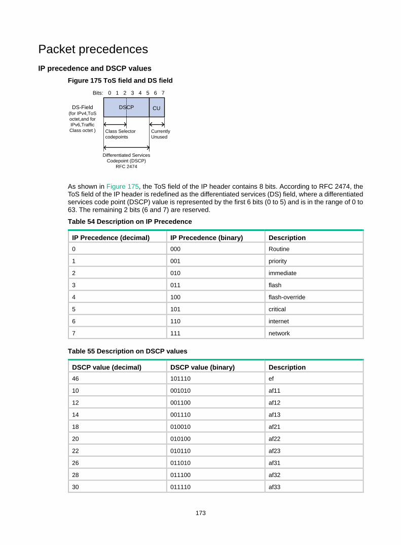
173
Packet precedences IP precedence and DSCP values
Figure 175 ToS field and DS field
As shown in Figure 175, the ToS field of the IP header contains 8 bits. According to RFC 2474, the ToS field of the IP header is redefined as the differentiated services (DS) field, where a differentiated services code point (DSCP) value is represented by the first 6 bits (0 to 5) and is in the range of 0 to 63. The remaining 2 bits (6 and 7) are reserved.
Table 54 Description on IP Precedence
IP Precedence (decimal) IP Precedence (binary) Description 0 000 Routine
1 001 priority
2 010 immediate
3 011 flash
4 100 flash-override
5 101 critical
6 110 internet
7 111 network
Table 55 Description on DSCP values
DSCP value (decimal) DSCP value (binary) Description 46 101110 ef
10 001010 af11
12 001100 af12
14 001110 af13
18 010010 af21
20 010100 af22
22 010110 af23
26 011010 af31
28 011100 af32
30 011110 af33
0 76
DSCP
Class Selector codepoints
Differentiated Services Codepoint (DSCP)
RFC 2474
CurrentlyUnused
DS-Field(for IPv4,ToS octet,and for IPv6,Traffic Class octet )
1 5432Bits:
CU

174
DSCP value (decimal) DSCP value (binary) Description 34 100010 af41
36 100100 af42
38 100110 af43
8 001000 cs1
16 010000 cs2
24 011000 cs3
32 100000 cs4
40 101000 cs5
48 110000 cs6
56 111000 cs7
0 000000 be (default)
802.1p priority 802.1p priority lies in Layer 2 packet headers and applies to occasions where Layer 3 header analysis is not needed and QoS must be assured at Layer 2.
Figure 176 An Ethernet frame with an 802.1Q tag header
As shown in Figure 176, the 4-byte 802.1Q tag header consists of the 2-byte tag protocol identifier (TPID, with a value of 0x8100) and the 2-byte tag control information (TCI). Figure 177 presents the format of the 802.1Q tag header. The priority in the 802.1Q tag header is called 802.1p priority, because its use is defined in IEEE 802.1p. Table 56 presents the values for 802.1p priority.
Figure 177 802.1Q tag header
Table 56 Description on 802.1p priority
802.1p priority (decimal) 802.1p priority (binary) Description 0 000 best-effort
1 001 background
2 010 spare
3 011 excellent-effort
1 0 0 0 0 0 0 1 0 0 0 0 0 0 0 Priority VLAN ID
TPID (Tag protocol identifier) TCI (Tag control information)
Byte 1 Byte 2
0
Byte 3 Byte 4
CFI
7 5 4 3 2 1 0 7 5 4 3 2 1 06 6 7 5 4 3 2 1 0 7 5 4 3 2 1 06 6

175
802.1p priority (decimal) 802.1p priority (binary) Description 4 100 controlled-load
5 101 video
6 110 voice
7 111 network-management
Queue scheduling In general, congestion management uses queuing technology. The system uses a certain queuing algorithm for traffic classification, and then uses a certain precedence algorithm to send the traffic. Each queuing algorithm handles a particular network traffic problem and has significant impacts on bandwidth resource assignment, delay, and jitter.
In this section, two common hardware queue scheduling algorithms Strict Priority (SP) queuing and Weighted Round Robin (WRR) queuing are introduced.
SP queuing SP queuing is designed for mission-critical applications, which require preferential service to reduce response delay when congestion occurs.
Figure 178 SP queuing
A typical switch provides eight queues per port. As shown in Figure 178, SP queuing classifies eight queues on a port into eight classes, numbered 7 to 0 in descending priority order.
SP queuing schedules the eight queues strictly according to the descending order of priority. It sends packets in the queue with the highest priority first. When the queue with the highest priority is empty, it sends packets in the queue with the second highest priority, and so on. You can assign mission-critical packets to the high priority queue to make sure they are always served first and common service (such as Email) packets to the low priority queues to be transmitted when the high priority queues are empty.
The disadvantage of SP queuing is that packets in the lower priority queues cannot be transmitted if the higher priority queues have packets. This might cause lower priority traffic to starve to death.
WRR queuing WRR queuing schedules all the queues in turn to make sure every queue can be served for a certain time, as shown in Figure 179.

176
Figure 179 WRR queuing
A typical switch provides eight output queues per port. WRR assigns each queue a weight value (represented by w7, w6, w5, w4, w3, w2, w1, or w0) to decide the proportion of resources assigned to the queue. On a 100 Mbps port, you can set the weight values of WRR queuing to 25, 25, 15, 15, 5, 5, 5, and 5 (corresponding to w7, w6, w5, w4, w3, w2, w1, and w0, respectively). In this way, the queue with the lowest priority is assured of at least 5 Mbps bandwidth, and the disadvantage of SP queuing that packets in low-priority queues might fail to be served for a long time is avoided.
Another advantage of WRR queuing is that while the queues are scheduled in turn, the service time for each queue is not fixed. If a queue is empty, the next queue will be scheduled immediately. This improves bandwidth resource use efficiency.
Basic WRR queuing contains multiple queues. You can configure the weight, percentage (or byte count) for each queue, and WRR schedules these queues based on the user-defined parameters in a round robin manner.
You can implement SP+WRR queue scheduling on a port by assigning some queues on the port to the SP scheduling group when you configure WRR. Packets in the SP scheduling group are scheduled preferentially by SP. When the SP scheduling group is empty, the other queues are scheduled by WRR.
Rate limit Rate limit is a traffic control method using token buckets. The rate limit of a physical interface specifies the maximum rate for forwarding packets (including critical packets). Rate limit can limit all the packets passing a physical interface.
Traffic evaluation and token bucket A token bucket can be considered as a container holding a certain number of tokens. The system puts tokens into the bucket at a set rate. When the token bucket is full, the extra tokens will overflow.

177
Figure 180 Evaluate traffic with the token bucket
The evaluation for the traffic specification is based on whether the number of tokens in the bucket can meet the need of packet forwarding. If the number of tokens in the bucket is enough to forward the packets (usually, one token is associated with a 1-bit forwarding authority), the traffic conforms to the specification, and the traffic is called "conforming traffic." Otherwise, the traffic does not conform to the specification, and the traffic is called "excess traffic."
A token bucket has the following configurable parameters: • Mean rate—Rate at which tokens are put into the bucket, or the permitted average rate of traffic.
It is usually set to the committed information rate (CIR). • Burst size—The capacity of the token bucket, or the maximum traffic size permitted in each
burst. It is usually set to the committed burst size (CBS). The set burst size must be greater than the maximum packet size.
One evaluation is performed on each arriving packet. In each evaluation, if the number of tokens in the bucket is enough, the traffic conforms to the specification and the tokens for forwarding the packet are taken away. If the number of tokens in the bucket is not enough, it means that too many tokens have been used and the traffic is excessive.
Working mechanism of rate limit With rate limit configured on an interface, all packets to be sent through the interface are firstly handled by the token bucket of rate limit. If the token bucket has enough tokens, packets can be forwarded. Otherwise, packets are put into QoS queues for congestion management. In this way, the traffic passing the physical interface is controlled.

178
Figure 181 Rate limit implementation
With a token bucket used for traffic control, when the token bucket has tokens, the bursty packets can be transmitted. When no tokens are available, packets cannot be transmitted until new tokens are generated in the token bucket. In this way, the traffic rate is restricted to the rate for generating tokens, the traffic rate is limited, and bursty traffic is allowed.
Priority mapping Concepts
When a packet enters a network, it is marked with a certain priority to indicate its scheduling weight or forwarding priority. Then, the intermediate nodes in the network process the packet according to the priority.
When a packet enters a device, the device assigns to the packet a set of predefined parameters (including the 802.1p priority, DSCP values, and local precedence). • For more information about 802.1p priority and DSCP values, see "Packet precedences." • Local precedence is a locally significant precedence that the device assigns to a packet. A local
precedence value corresponds to an output queue. Packets with the highest local precedence are processed preferentially.
The switch provides the following priority trust modes on a port: • Trust packet priority—The switch assigns to the packet the priority parameters corresponding
to the packet's priority from the mapping table. • Trust port priority—The switch assigns a priority to a packet by mapping the priority of the
receiving port.
You can select one priority trust mode as needed. Figure 182 shows the process of priority mapping on a device.

179
Figure 182 Priority mapping process
Introduction to priority mapping tables The switch provides the following types of priority mapping tables: • CoS to Queue—802.1p--to-local mapping table. • DSCP to Queue—DSCP-to-local mapping table, which applies to only IP packets.
Table 57 and Table 58 list the default priority mapping tables.
Table 57 Default CoS to Queue mapping table
Input CoS value Local precedence (Queue) 0 2
1 0
2 1
3 3
4 4
5 5
6 6
7 7
Table 58 Default DSCP to Queue mapping table
Input DSCP value Local precedence (Queue) 0 to 7 0
8 to 15 1
16 to 23 2
24 to 31 3
32 to 39 4
40 to 47 5
48 to 55 6
56 to 63 7

180
Recommended QoS configuration procedures Recommended queue scheduling configuration procedure
Step Remarks
1. Configuring queue scheduling on a port Optional. Configure the queue scheduling mode for a port.
Recommended rate limit configuration procedure
Step Remarks
1. Configuring rate limit on a port Required. Limit the rate of incoming packets or outgoing packets of a physical port.
Recommended priority mapping table configuration procedure
Step Remarks
1. Configuring priority mapping tables Required. Set priority mapping tables.
Recommended priority trust mode configuration procedure
Step Remarks
1. Configuring priority trust mode on a port Required. Set the priority trust mode of a port.
Configuring queue scheduling on a port 1. Select QoS > Queue from the navigation tree. 2. Click Setup to enter the queue scheduling configuration page.

181
Figure 183 Configuring queue scheduling
3. Configure queue scheduling on a port as described in Table 59. 4. Click Apply.
Table 59 Configuration items
Item Description
WRR Setup
WRR
Enable or disable the WRR queue scheduling mechanism on selected ports. The following options are available: • Enable—Enables WRR on selected ports. • Not Set—Restores the default queuing algorithm on selected ports.
Queue Select the queue to be configured. The value range for a queue ID is 0 to 7.
Group
Specify the group the current queue is to be assigned to. This list is available after you select a queue ID. The following groups are available for selection: • SP—Assigns a queue to the SP group. • 1—Assigns a queue to WRR group 1.
Weight Set a weight for the current queue. This list is available when group 1 is selected.
Please select port(s) Click to select ports to be configured with queuing on the chassis front panel.
Configuring rate limit on a port 1. Select QoS > Line rate from the navigation tree. 2. Click the Setup tab to enter the rate limit configuration page.

182
Figure 184 Configuring rate limit on a port
3. Configure rate limit on a port as described in Table 60. 4. Click Apply.
Table 60 Configuration items
Item Description Please select an interface type Select the types of interfaces to be configured with rate limit.
Rate Limit Enable or disable rate limit on the specified port.
Direction
Select a direction in which the rate limit is to be applied. • Inbound—Limits the rate of packets received on the specified port. • Outbound—Limits the rate of packets sent by the specified port. • Both—Limits the rate of packets received and sent by the specified
port.
CIR Set the committed information rate (CIR), the average traffic rate.
Please select port(s) Specify the ports to be configured with rate limit. Click the ports to be configured with rate limit in the port list. You can select one or more ports.
Configuring priority mapping tables 1. Select QoS > Priority Mapping from the navigation tree.
Figure 185 Configuring priority mapping tables
2. Configure a priority mapping table as described in Table 61. 3. Click Apply.

183
Table 61 Configuration items
Item Description
Mapping Type Select the priority mapping table to be configured: • CoS to Queue. • DSCP to Queue.
Input Priority Value Set the output priority value for an input priority value.
Output Priority Value
Restore Click Restore to display the default settings of the current priority mapping table on the page. To restore the priority mapping table to the default, click Apply.
Configuring priority trust mode on a port 1. Select QoS > Port Priority from the navigation tree.
Figure 186 Configuring port priorities
2. Click the icon for a port.
Figure 187 Modifying the port priority
3. Configure the port priority for a port as described in Table 62. 4. Click Apply.

184
Table 62 Configuration items
Item Description Interface Interface to be configured.
Priority Set a local precedence value for the port.
Trust Mode
Select a priority trust mode for the port: • Untrust—Packet priority is not trusted. • Dot1p—802.1p priority of the incoming packets is trusted and used for priority mapping.• DSCP—DSCP value of the incoming packets is trusted and used for priority mapping.

185
QoS configuration example
Network requirements As shown in Figure 188, the switch receives three packet flows with DSCP values 10, 18, and 46.
Configure queue scheduling on the switch, so packets with DSCP values 10, 18, and 46 are forwarded at a 1/2/4 ratio.
Figure 188 Network diagram
Configuring the switch 1. Configure the priority trust mode as DSCP:
a. Select QoS > Port Priority from the navigation tree.
b. Click the icon for GigabitEthernet 1/0/1. c. Select DSCP in the Trust Mode list. d. Click Apply. e. Configure GigabitEthernet 1/0/2 and GigabitEthernet 1/0/3 in the same way GigabitEthernet
1/0/1 is configured. (Details not shown.)
Figure 189 Configuring the priority trust mode as DSCP
2. Configure the priority mapping table: a. Select QoS > Priority Mapping from the navigation tree. b. Select DSCP to Queue in the Mapping Type list. c. Select output values 2, 4, and 6 for input values 16, 18, and 46, respectively. d. Click Apply.

186
Figure 190 Configuring the priority mapping table
3. Configure WRR: a. Select QoS > Queue > Setup from the navigation tree. b. Select 2 in the Queue list, select 1 in the Group list, and select 5 in the Weight list. c. Click GigabitEthernet 1/0/4 on the chassis front panel to select it. d. Click Apply.
Figure 191 Configuring WRR for queue 2
e. Select 4 in the Queue list, select 1 in the Group list, and select 10 in the Weight list. f. Click GigabitEthernet 1/0/4 on the chassis front panel to select it. g. Click Apply.

187
Figure 192 Configuring WRR for queue 4
h. Select 6 in the Queue list, select 1 in the Group list, and select 20 in the Weight list. i. Click GigabitEthernet 1/0/4 on the chassis front panel to select it. j. Click Apply.
Figure 193 Configuring WRR for queue 6

188
Document conventions and icons
Conventions This section describes the conventions used in the documentation.
Port numbering in examples The port numbers in this document are for illustration only and might be unavailable on your device.
Command conventions
Convention Description Boldface Bold text represents commands and keywords that you enter literally as shown.
Italic Italic text represents arguments that you replace with actual values.
[ ] Square brackets enclose syntax choices (keywords or arguments) that are optional.
{ x | y | ... } Braces enclose a set of required syntax choices separated by vertical bars, from which you select one.
[ x | y | ... ] Square brackets enclose a set of optional syntax choices separated by vertical bars, from which you select one or none.
{ x | y | ... } * Asterisk marked braces enclose a set of required syntax choices separated by vertical bars, from which you select at least one.
[ x | y | ... ] * Asterisk marked square brackets enclose optional syntax choices separated by vertical bars, from which you select one choice, multiple choices, or none.
&<1-n> The argument or keyword and argument combination before the ampersand (&) sign can be entered 1 to n times.
# A line that starts with a pound (#) sign is comments.
GUI conventions
Convention Description
Boldface Window names, button names, field names, and menu items are in Boldface. For example, the New User window appears; click OK.
> Multi-level menus are separated by angle brackets. For example, File > Create > Folder.
Symbols
Convention Description
WARNING! An alert that calls attention to important information that if not understood or followed can result in personal injury.
CAUTION: An alert that calls attention to important information that if not understood or followed can result in data loss, data corruption, or damage to hardware or software.
IMPORTANT: An alert that calls attention to essential information.
NOTE: An alert that contains additional or supplementary information.
TIP: An alert that provides helpful information.

189
Network topology icons Convention Description
Represents a generic network device, such as a router, switch, or firewall.
Represents a routing-capable device, such as a router or Layer 3 switch.
Represents a generic switch, such as a Layer 2 or Layer 3 switch, or a router that supports Layer 2 forwarding and other Layer 2 features.
Represents an access controller, a unified wired-WLAN module, or the access controller engine on a unified wired-WLAN switch.
Represents an access point.
Represents a wireless terminator unit.
Represents a wireless terminator.
Represents a mesh access point.
Represents omnidirectional signals.
Represents directional signals.
Represents a security product, such as a firewall, UTM, multiservice security gateway, or load balancing device.
Represents a security card, such as a firewall, load balancing, NetStream, SSL VPN, IPS, or ACG card.
TT
TT

190
Support and other resources
Accessing Hewlett Packard Enterprise Support • For live assistance, go to the Contact Hewlett Packard Enterprise Worldwide website:
www.hpe.com/assistance • To access documentation and support services, go to the Hewlett Packard Enterprise Support
Center website: www.hpe.com/support/hpesc
Information to collect • Technical support registration number (if applicable) • Product name, model or version, and serial number • Operating system name and version • Firmware version • Error messages • Product-specific reports and logs • Add-on products or components • Third-party products or components
Accessing updates • Some software products provide a mechanism for accessing software updates through the
product interface. Review your product documentation to identify the recommended software update method.
• To download product updates, go to either of the following: Hewlett Packard Enterprise Support Center Get connected with updates page:
www.hpe.com/support/e-updates Software Depot website:
www.hpe.com/support/softwaredepot • To view and update your entitlements, and to link your contracts, Care Packs, and warranties
with your profile, go to the Hewlett Packard Enterprise Support Center More Information on Access to Support Materials page: www.hpe.com/support/AccessToSupportMaterials
IMPORTANT: Access to some updates might require product entitlement when accessed through the HewlettPackard Enterprise Support Center. You must have an HP Passport set up with relevant entitlements.

191
Websites
Website Link Networking websites
Hewlett Packard Enterprise Information Library for Networking www.hpe.com/networking/resourcefinder
Hewlett Packard Enterprise Networking website www.hpe.com/info/networking
Hewlett Packard Enterprise My Networking website www.hpe.com/networking/support
Hewlett Packard Enterprise My Networking Portal www.hpe.com/networking/mynetworking
Hewlett Packard Enterprise Networking Warranty www.hpe.com/networking/warranty
General websites
Hewlett Packard Enterprise Information Library www.hpe.com/info/enterprise/docs
Hewlett Packard Enterprise Support Center www.hpe.com/support/hpesc
Hewlett Packard Enterprise Support Services Central ssc.hpe.com/portal/site/ssc/
Contact Hewlett Packard Enterprise Worldwide www.hpe.com/assistance
Subscription Service/Support Alerts www.hpe.com/support/e-updates
Software Depot www.hpe.com/support/softwaredepot
Customer Self Repair (not applicable to all devices) www.hpe.com/support/selfrepair
Insight Remote Support (not applicable to all devices) www.hpe.com/info/insightremotesupport/docs
Customer self repair Hewlett Packard Enterprise customer self repair (CSR) programs allow you to repair your product. If a CSR part needs to be replaced, it will be shipped directly to you so that you can install it at your convenience. Some parts do not qualify for CSR. Your Hewlett Packard Enterprise authorized service provider will determine whether a repair can be accomplished by CSR.
For more information about CSR, contact your local service provider or go to the CSR website:
www.hpe.com/support/selfrepair
Remote support Remote support is available with supported devices as part of your warranty, Care Pack Service, or contractual support agreement. It provides intelligent event diagnosis, and automatic, secure submission of hardware event notifications to Hewlett Packard Enterprise, which will initiate a fast and accurate resolution based on your product’s service level. Hewlett Packard Enterprise strongly recommends that you register your device for remote support.
For more information and device support details, go to the following website:
www.hpe.com/info/insightremotesupport/docs
Documentation feedback Hewlett Packard Enterprise is committed to providing documentation that meets your needs. To help us improve the documentation, send any errors, suggestions, or comments to Documentation Feedback ([email protected]). When submitting your feedback, include the document title,

192
part number, edition, and publication date located on the front cover of the document. For online help content, include the product name, product version, help edition, and publication date located on the legal notices page.

193
Index Numerics
802.x QoS packet 802.1p priority, 174
A
adding NMM local port mirroring local group, 54 rules to SNMP view, 71 Web device local user, 57
aggregate interface (Ethernet link aggregation), 116 aggregating
link, 112 aging
MAC address table timer, 110 attribute
local user and user group configuration, 145 authenticating
local user and user group configuration, 145 local user configuration, 145 user group configuration, 147
B
backing up Web device configuration, 36
bandwidth QoS policy configuration, 171
bidirectional NMM port mirroring, 50
blackhole entry MAC address table, 108
buttons on webpage, 12
C
cable status testing, 62
choosing Ethernet link aggregation selected state, 112 Ethernet link aggregation unselected state, 112
class (Ethernet link aggregation port configuration), 112 class-two
Ethernet link aggregation MAC address learning configuration class, 112 Ethernet link aggregation port isolation configuration class, 112 Ethernet link aggregation VLAN configuration class, 112
configuration wizard basic service setup, 16
configuring basic device settings, 24 energy saving, 64 energy saving on port, 64 Ethernet link aggregation and LACP, 112, 120 Ethernet link aggregation group, 114 Ethernet link dynamic aggregation group, 115 Ethernet link static aggregation group, 114 flow interval, 63 idle timeout period, 24 IGMP snooping, 124, 133 IGMP snooping port function, 131 local user, 145 local user and user group, 145 loopback detection, 168, 168 loopback detection (global), 168 loopback detection (port-specific), 169 loopback test, 60, 60 MAC address table, 108, 109, 110 management IP address, 18 NMM local port mirroring, 53 NMM local port mirroring group, 51 NMM local port mirroring group monitor port, 55 NMM local port mirroring group ports, 52 NMM local port mirroring group source ports, 54 NMM SNMP, 66 port link type, 94 port-based VLAN, 88 priority mapping table, 182 priority trust mode, 183 PVID, 95 QoS, 185 QoS policy, 171 queue scheduling on port, 180, 181 SNMP community, 72 SNMP group, 73 SNMP trap function, 76 SNMP user, 74 SNMP view, 70 SNMPv1, 78 SNMPv2c, 78 SNMPv3, 81 system name, 24 system parameters, 17 system time, 28

194
system time (by using NTP), 29, 31 system time (manually), 28 user group, 147 VCT, 62 VLAN interface, 104 Web device configuration management, 36 Web device user management, 57 Web interface, 2 Web service management, 138, 138
creating Ethernet link aggregation group, 115 SNMP view, 70 VLAN, 93 VLAN interface, 104
D
destination NMM port mirroring, 50
device basic settings configuration, 24 idle timeout period configuration, 24 NMM local port mirroring configuration, 53 NMM local port mirroring group monitor port, 55 NMM port mirroring configuration, 50 NMM SNMP configuration, 66 port management, 41, 46 SNMPv1 configuration, 78 SNMPv2c configuration, 78 SNMPv3 configuration, 81 syslog configuration, 33 system name configuration, 24 VCT configuration, 62 Web common page features, 12 Web configuration backup, 36 Web configuration management, 36 Web configuration reset, 38 Web configuration restoration, 36 Web configuration save, 37 Web device local user adding, 57 Web device privilege level switching, 59 Web device super password setting, 58 Web device user management, 57 Web file displaying, 39 Web file download, 39 Web file management, 39 Web file removing, 40 Web file upload, 40 Web interface, 7 Web interface HTTP login, 6 Web interface logout, 7
Web main boot file specifying, 40 Web service management, 138, 138 Web user level, 8 Web-based NM functions, 8
device information displaying device information, 21, 22
device management device reboot, 26 diagnostic information, 27 electronic label, 26 software upgrade, 25
diagnostic tools, 140
direction NMM port mirroring (bidirectional), 50 NMM port mirroring (inbound), 50 NMM port mirroring (outbound), 50
displaying all operation parameters for a port, 45 current system time, 28 Ethernet link aggregation aggregate interface, 116 Ethernet link aggregation LACP-enabled port, 118 IGMP snooping multicast forwarding entries, 132 interface statistics, 86 MAC address table, 109 port operation parameters, 44 SNMP packet statistics, 78 specified operation parameter for all ports, 44 syslogs, 33 Web device file, 39 Web page display, 13
downloading Web device file, 39
dropping unknown multicast data enable (globally), 129
DSCP QoS packet IP precedence and DSCP values, 173
dynamic Ethernet link aggregation dynamic mode, 114 Ethernet link aggregation mode, 113 Ethernet link dynamic aggregation group configuration, 115 IP multicast IGMP snooping dynamic port, 125 MAC address table dynamic aging timer, 110 MAC address table entry, 108
E
enabling

195
IP multicast dropping unknown multicast data (globally), 129 IP multicast IGMP snooping (globally), 128 IP multicast IGMP snooping (in a VLAN), 129 SNMP agent, 68
encapsulating VLAN frame encapsulation, 87
energy saving configuring energy saving, 64 port-based configuration, 64
entering configuration wizard homepage, 16
Ethernet link aggregation and LACP, 112 loopback detection configuration, 168, 168 loopback test configuration, 60, 60 MAC address table configuration, 108, 109, 110 NMM port mirroring configuration, 50 port-based VLAN configuration, 88 VLAN configuration, 87, 99 VLAN frame encapsulation, 87 VLAN type, 88
Ethernet link aggregation aggregate interface, 112, 116 aggregation group, 112 basic concepts, 112 configuration, 112, 120 dynamic group configuration, 115 dynamic mode, 114 group configuration, 114 group creation, 115 LACP, 112 LACP priority, 117 LACP-enabled port, 118 member port state, 112 modes, 113 operational key, 112 port configuration class, 112 static group configuration, 114 static mode, 113
evaluating QoS traffic, 176
F
finishing configuration wizard, 19
flow interval configuration, 63 viewing port traffic statistics, 63
forwarding
QoS token bucket, 176 frame
MAC address learning, 108 MAC address table configuration, 108, 109, 110 port-based VLAN frame handling, 90 VLAN frame encapsulation, 87
function Web search, 13 Web sort, 15 Web-based NM functions, 8
G
general query IGMP snooping, 126
group Ethernet link aggregation group, 112 Ethernet link aggregation group configuration, 114 Ethernet link aggregation group creation, 115 Ethernet link aggregation LACP, 112 Ethernet link aggregation member port state, 112 Ethernet link dynamic aggregation group configuration, 115 Ethernet link static aggregation group configuration, 114 NMM local port mirroring group monitor port, 55 NMM local port mirroring group port, 52 NMM local port mirroring group source port, 54 NMM port mirroring group, 50
guidelines loopback test, 60
H
hardware congestion management SP queuing, 175, 175 WRR queuing, 175, 175
HTTP Web interface login, 6
I
ICMP ping command, 140
icons on webpage, 12 IGMP snooping
aging timer for dynamic port, 125 basic concepts, 124 configuration, 124 configuring, 133 configuring port functions, 131 displaying IGMP snooping multicast forwarding entries, 132 enable (globally), 128

196
enable (in a VLAN), 129 enabling dropping unknown multicast data (globally), 129 enabling IGMP snooping (globally), 128 enabling IGMP snooping (in a VLAN), 129 general query, 126 how it works, 126 leave message, 127 membership report, 126 protocols and standards, 127 related ports, 124
implementing NMM local port mirroring, 50
inbound NMM port mirroring, 50
interface Ethernet aggregate interface, 112
interface statistics displaying, 86
Internet NMM SNMP configuration, 66 SNMPv1 configuration, 78 SNMPv2c configuration, 78 SNMPv3 configuration, 81
IP addressing traceroute, 140
K
key Ethernet link aggregation operational key, 112
L
LACP configuration, 112, 120 Ethernet link aggregation, 112
LACP-enabled port (Ethernet link aggregation), 118 LAN
VLAN configuration, 87, 99 Layer 2
Ethernet aggregate interface, 112 Ethernet aggregation group, 112 Ethernet link aggregation and LACP configuration, 112 Ethernet link aggregation group configuration, 114 Ethernet link aggregation group creation, 115 Ethernet link dynamic aggregation group configuration, 115 Ethernet link static aggregation group configuration, 114 loopback detection configuration, 168, 168
loopback test configuration, 60, 60 NMM port mirroring configuration, 50 port-based VLAN configuration, 88 VLAN configuration, 87, 99 VLAN type, 88
Layer 2 aggregate interface management, 41
Layer 2 Ethernet port management, 41, 46
Layer 3 NMM port mirroring configuration, 50 traceroute, 140 traceroute node failure identification, 142
learning MAC address, 108
leave message IP multicast IGMP snooping, 127
link aggregation, 112
local port mirroring adding local group, 54 configuration, 51 local group monitor port, 55 local group port, 52 local group source port, 54 NMM, 50
logging in Web interface HTTP login, 6
logging out Web interface logout, 7
loopback detection configuration, 168, 168 configuration (global), 168 configuration (port-specific), 169
loopback test configuration, 60, 60 guidelines, 60
M
MAC address Ethernet link aggregation MAC address learning configuration class, 112 VLAN frame encapsulation, 87
MAC address table address learning, 108 configuration, 108, 109, 110 displaying, 109 dynamic aging timer, 110 entry creation, 108 entry types, 108 manual entries, 108

197
Management Information Base. Use MIB managing
port, 41, 46 Web device configuration, 36, 39 Web device file management, 39 Web device user, 57 Web devices, 25 Web services, 138, 138
mechanism rate limit, 177
member IGMP snooping member port, 124
membership report IGMP snooping, 126
message IP multicast IGMP snooping leave, 127
MIB SNMP, 66
mirroring port. See port mirroring
mode Ethernet link aggregation dynamic, 113 Ethernet link aggregation dynamic mode, 114 Ethernet link aggregation static, 113 Ethernet link aggregation static mode, 113
modifying port, 98 VLAN, 97 VLAN interface, 105
multicast configuring IGMP snooping, 133 displaying IGMP snooping multicast forwarding entries, 132 enabling dropping unknown multicast data (globally), 129 enabling IGMP snooping (globally), 128 enabling IGMP snooping (in a VLAN), 129 IGMP snooping configuration, 124 IGMP snooping port function configuration, 131
multiport unicast entry (MAC address table), 108
N
network all operation parameters for a port, 45 device idle timeout period configuration, 24 device system name configuration, 24 Ethernet link aggregation aggregate interface, 116 Ethernet link aggregation dynamic mode, 114 Ethernet link aggregation LACP, 112
Ethernet link aggregation LACP priority, 117 Ethernet link aggregation LACP-enabled port, 118 Ethernet link aggregation modes, 113 Ethernet link aggregation operational key, 112 Ethernet link aggregation static mode, 113 MAC address table dynamic aging timer, 110 MAC address table entry types, 108 NMM local port mirroring group monitor port, 55 NMM local port mirroring group port, 52 NMM local port mirroring group source port, 54 port operation parameters, 41, 44 QoS traffic evaluation, 176 specified operation parameter for all ports, 44 VLAN type, 88 Web common page features, 12 Web device configuration backup, 36 Web device configuration reset, 38 Web device configuration restoration, 36 Web device configuration save, 37 Web device file displaying, 39 Web device file download, 39 Web device file removing, 40 Web device file upload, 40 Web device local user adding, 57 Web device main boot file specifying, 40 Web device privilege level switching, 59 Web device super password setting, 58 Web interface, 7 Web interface HTTP login, 6
network management basic device settings configuration, 24 configuration wizard, 16 Ethernet link aggregation and LACP configuration, 112, 120 flow interval, 63 loopback detection, 168, 168 loopback test, 60, 60 MAC address table configuration, 108, 109, 110 NMM local port mirroring configuration, 53 NMM port mirroring configuration, 50 NMM SNMP configuration, 66 ping, 140 port management, 41, 46 port-based VLAN configuration, 88 QoS configuration, 185 QoS policy configuration, 171 QoS priority mapping, 178 SNMPv1 configuration, 78 SNMPv2c configuration, 78 SNMPv3 configuration, 81

198
syslog configuration, 33 traceroute, 140 VLAN configuration, 87, 99 Web device configuration management, 36 Web device file management, 39 Web device management, 25 Web device user management, 57 Web interface logout, 7 Web service management, 138, 138 Web user level, 8 Web-based NM functions, 8
NMM local port mirroring configuration, 53 local port mirroring group, 51 local port mirroring group monitor port, 55 local port mirroring group port, 52 local port mirroring group source port, 54 local port mirroring local group, 54 port mirroring configuration, 50 port mirroring recommended procedure, 51 SNMP configuration, 66 SNMP mechanism, 66 SNMP protocol versions, 67 SNMPv1 configuration, 78 SNMPv2c configuration, 78 SNMPv3 configuration, 81 system maintenance, 140 traceroute, 140
NMS SNMP protocol versions, 67
NTP configuring system time, 29, 31 system time configuration, 28
O
operational key (Ethernet link aggregation), 112 outbound
NMM port mirroring, 50
P
packet NMM port mirroring configuration, 50 QoS policy configuration, 171 QoS priority mapping, 178 QoS traffic evaluation, 176
packet precedence, 173 ping
address reachability determination, 140, 141 system maintenance, 140
policy QoS policy configuration, 171
port all operation parameters for a port, 45 configuring energy saving, 64 configuring IGMP snooping, 133 Ethernet aggregate interface, 112 Ethernet link aggregation aggregate interface, 116 Ethernet link aggregation and LACP configuration, 120 Ethernet link aggregation configuration, 112 Ethernet link aggregation dynamic mode, 114 Ethernet link aggregation group, 112 Ethernet link aggregation group configuration, 114 Ethernet link aggregation group creation, 115 Ethernet link aggregation LACP, 112 Ethernet link aggregation LACP priority, 117 Ethernet link aggregation LACP-enabled port, 118 Ethernet link aggregation member port state, 112 Ethernet link aggregation modes, 113 Ethernet link aggregation operational key, 112 Ethernet link aggregation port configuration class, 112 Ethernet link aggregation static mode, 113 Ethernet link dynamic aggregation group configuration, 115 Ethernet link static aggregation group configuration, 114 IGMP snooping configuration, 124 IGMP snooping member port, 124 IGMP snooping port function configuration, 131 IGMP snooping related ports, 124 IGMP snooping router port, 124 IP multicast IGMP snooping aging timer for dynamic port, 125 loopback detection configuration, 168, 168 loopback test configuration, 60, 60 MAC address learning, 108 MAC address table configuration, 108, 109, 110 management, 41, 46 mirroring. See port mirroring modification, 98 operation parameters, 41, 44 specified operation parameter for all ports, 44 VLAN port link type, 88
port isolation Ethernet link aggregation class-two configuration class, 112
port link type configuration, 94
port mirroring

199
adding local group, 54 configuration, 50 configuration restrictions, 51 destination, 50 direction (bidirectional), 50 direction (inbound), 50 direction (outbound), 50 local, 50 local configuration, 51 local group monitor port, 55 local group port, 52 local group source port, 54 local mirroring configuration, 53 mirroring group, 50 recommended procedure, 51 source, 50 terminology, 50
port-based energy saving configuration, 64
port-based VLAN configuration, 88 port frame handling, 90 port link type, 88 PVID, 89
precedence QoS priority mapping, 178
priority Ethernet link aggregation LACP, 112 port LACP priority, 117 QoS packet 802.1p priority, 174 QoS packet IP precedence and DSCP values, 173 QoS scheduling, 175
priority mapping map, 179
procedure adding NMM local port mirroring group, 54 adding rules to SNMP view, 71 adding Web device local user, 57 backing up Web device configuration, 36 configuring device idle timeout period, 24 configuring device system name, 24 configuring energy saving on port, 64 configuring Ethernet link aggregation and LACP, 120 configuring Ethernet link aggregation group, 114 configuring Ethernet link dynamic aggregation group, 115 configuring Ethernet link static aggregation group, 114
configuring IGMP snooping, 133 configuring IGMP snooping port function, 131 configuring local user, 145 configuring local user and user group, 145 configuring loopback detection (global), 168 configuring loopback detection (port-specific), 169 configuring MAC address table, 110 configuring management IP address, 18 configuring NMM local port mirroring, 53 configuring NMM local port mirroring group, 51 configuring NMM local port mirroring group monitor port, 55 configuring NMM local port mirroring group ports, 52 configuring NMM local port mirroring group source ports, 54 configuring port link type, 94 configuring priority mapping table, 180, 182 configuring priority trust mode, 180 configuring priority trust mode on port, 183 configuring PVID for port, 95 configuring QoS, 185 configuring queue scheduling, 180 configuring queue scheduling on port, 180, 181 configuring rate limit, 180 configuring SNMP community, 72 configuring SNMP group, 73 configuring SNMP trap function, 76 configuring SNMP user, 74 configuring SNMP view, 70 configuring SNMPv1, 78 configuring SNMPv2c, 78 configuring SNMPv3, 81 configuring system parameters, 17 configuring system time (by using NTP), 29, 31 configuring system time (manually), 28 configuring user group, 147 configuring VLAN interface, 104 creating Ethernet link aggregation group, 115 creating SNMP view, 70 creating VLAN, 93 creating VLAN interface, 104 displaying all operation parameters for a port, 45 displaying basic system information, 21 displaying current system time, 28 displaying device information, 22 displaying IGMP snooping multicast forwarding entries, 132 displaying interface statistics, 86 displaying port operation parameters, 44

200
displaying recent system logs, 22 displaying SNMP packet statistics, 78 displaying specified operation parameter for all ports, 44 displaying syslogs, 33 displaying system information, 21 displaying system resource state, 22 displaying Web device file, 39 downloading Web device file, 39 enabling dropping unknown multicast data (globally), 129 enabling IGMP snooping (globally), 128 enabling IGMP snooping (in a VLAN), 129 enabling SNMP agent, 68 entering configuration wizard homepage, 16 finishing configuration wizard, 19 identifying node failure with traceroute, 142 logging in to Web interface through HTTP, 6 logging out of Web interface, 7 managing port, 41, 46 modifying port, 98 modifying VLAN, 97 modifying VLAN interface, 105 NMM port mirroring, 51 removing Web device file, 40 resetting Web device configuration, 38 restoring Web device configuration, 36 saving Web device configuration, 37 selecting VLAN, 96 setting buffer capacity and refresh interval, 35 setting log host, 34 setting MAC address table dynamic aging timer, 110 setting port operation parameters, 41 setting refresh period, 22 setting Web device super password, 58 specifying Web device main boot file, 40 switching to Web device management level, 59 testing cable status, 62 testing connectivity with ping, 141 uploading Web device file, 40 viewing port traffic statistics, 63
protocols and standards IGMP snooping, 127 NMM SNMP configuration, 66 SNMP versions, 67
PVID configuration, 95
PVID (port-based VLAN), 89
Q
QoS configuration, 185 hardware congestion management SP queuing, 175, 175 hardware congestion management WRR queuing, 175, 175 packet precedence, 173 policy configuration, 171 policy port application, 180, 181, 183 priority mapping, 178 priority mapping table, 179 queue scheduling, 175 rate limit, 176 token bucket, 176 traffic evaluation, 176
querying IGMP snooping general query, 126
queuing QoS hardware congestion management SP queuing, 175, 175 QoS hardware congestion management WRR queuing, 175, 175 SP and WRR, 175
R
rate rate limit, 176
rate limit working mechanism, 177
rebooting device, 26
removing Web device file, 40
reporting IGMP snooping membership, 126
resetting Web device configuration, 38
restoring Web device configuration, 36
restrictions NMM port mirroring configuration, 51 Web interface login, 2
router IGMP snooping router port, 124
routing configuring IGMP snooping, 133 displaying IGMP snooping multicast forwarding entries, 132 enabling dropping unknown multicast data (globally), 129 enabling IGMP snooping (globally), 128 enabling IGMP snooping (in a VLAN), 129

201
IGMP snooping configuration, 124 IGMP snooping port function configuration, 131 port-based VLAN configuration, 88 QoS priority mapping, 178 VLAN type, 88
S
saving Web device configuration, 37
searching Web search function, 13 Web sort function, 15
seleting VLAN, 96
service QoS policy configuration, 171
service management FTP service, 138 HTTP service, 138 HTTPS service, 138
setting buffer capacity and refresh interval, 35 LACP priority, 117 log host, 34 MAC address table dynamic aging timer, 110 port operation parameters, 41 refresh period, 22 Web device super password, 58
Simple Network Management Protocol. Use SNMP SNMP
agent, 66 agent enabling, 68 community configuration, 72 configuration, 66 group configuration, 73 manager, 66 mechanism, 66 MIB, 66 packet statistics displaying, 78 protocol versions, 67 SNMPv1 configuration, 78 SNMPv2c configuration, 78 SNMPv3 configuration, 81 trap function configuration, 76 user configuration, 74 view configuration, 70 view creating, 70
SNMP view rules adding, 71
SNMPv1 configuration, 78 protocol version, 67
SNMPv2c configuration, 78 protocol version, 67
SNMPv3 configuration, 81 protocol version, 67
source NMM port mirroring, 50
SP queuing classifications, 175, 175
specifying Web device main boot file, 40
state Ethernet link aggregation member port state, 112
static Ethernet link aggregation mode, 113 Ethernet link aggregation static mode, 113 Ethernet link static aggregation group configuration, 114 MAC address table entry, 108
summary displaying basic system information, 21 displaying device information, 21, 22 displaying recent system logs, 22 displaying system information, 21, 21 displaying system resource state, 22 setting refresh period, 22
switching MAC address table configuration, 108, 109, 110 port management, 41, 46 VLAN configuration, 87, 99 Web device privilege level, 59
syslog configuration, 33 display, 33 setting buffer capacity and refresh interval, 35 setting log host, 34
system administration basic device settings configuration, 24 configuration wizard, 16 device idle timeout period configuration, 24 device system name configuration, 24 ping, 140 traceroute, 140, 140 Web common page features, 12 Web device configuration backup, 36 Web device configuration management, 36

202
Web device configuration reset, 38 Web device configuration restoration, 36 Web device configuration save, 37 Web device file displaying, 39 Web device file download, 39 Web device file management, 39 Web device file removing, 40 Web device file upload, 40 Web device local user adding, 57 Web device main boot file specifying, 40 Web device management, 25 Web device privilege level switching, 59 Web device super password setting, 58 Web device user management, 57 Web interface, 7 Web interface HTTP login, 6 Web interface logout, 7 Web service management, 138, 138 Web user level, 8 Web-based NM functions, 8
system information displaying basic system information, 21 displaying recent system logs, 22 displaying system information, 21, 21 displaying system resource state, 22
system time configuration, 28 configuration (by using NTP), 31 configuring system time (by using NTP), 29 configuring system time (manually), 28 displaying current system time, 28
T
table MAC address, 108, 109, 110
testing cable status, 62
time Ethernet link aggregation LACP timeout interval, 112
timer IP multicast IGMP snooping dynamic port aging timer, 125 MAC address table dynamic aging timer, 110
token bucket QoS traffic forwarding, 176
traceroute IP address retrieval, 140, 142 node failure detection, 140, 142 system maintenance, 140
traffic
QoS policy configuration, 171 QoS priority map table, 179 QoS token bucket, 176 QoS traffic evaluation, 176
type IP subnet VLAN, 88 MAC address VLAN, 88 policy VLAN, 88 port type VLAN, 88 protocol VLAN, 88
U
unicast MAC address table configuration, 108, 109, 110 MAC address table multiport unicast entry, 108
upgrading device software, 25
uploading Web device file, 40
user level Web user level, 8
V
VCT configuration, 62
viewing device diagnostic information, 27 device electronic label, 26
Virtual Cable Test. Use VCT Virtual Local Area Network. Use VLAN VLAN
configuration, 87, 99 configuration guidelines, 103 configuring, 87, 99 configuring IGMP snooping, 133 creation, 93 displaying IGMP snooping multicast forwarding entries, 132 enabling IGMP snooping (in a VLAN), 129 Ethernet link aggregation class-two configuration class, 112 frame encapsulation, 87 IGMP snooping configuration, 124 IGMP snooping port function configuration, 131 IP subnet type VLAN, 88 MAC address type VLAN, 88 modification, 97 NMM local port mirroring group monitor port, 55 NMM local port mirroring group port, 52 NMM local port mirroring group source port, 54 NMM port mirroring configuration, 50

203
policy type VLAN, 88 port link type, 88 port type, 88 port type VLAN, 88 port-based configuration, 88 port-based VLAN frame handling, 90 protocol type VLAN, 88 PVID, 89 selection, 96
VLAN interface configuration, 104 configuration guidelines, 107 creation, 104 modification, 105
W
Web buttons on webpage, 12 common page features, 12 configuration, 2 configuration wizard, 16 configuring port link type, 94 configuring PVID for port, 95 configuring VLAN interface, 104 creating VLAN, 93 creating VLAN interface, 104 device basic settings configuration, 24 device configuration backup, 36 device configuration management, 36 device configuration reset, 38 device configuration restoration, 36 device configuration save, 37 device file displaying, 39 device file download, 39 device file management, 39 device file removing, 40 device file upload, 40 device idle timeout period configuration, 24 device local user adding, 57 device main boot file specifying, 40 device management, 25 device privilege level switching, 59 device reboot, 26 device software upgrade, 25 device super password setting, 58 device system name configuration, 24 device user management, 57 displaying interface statistics, 86 entering configuration wizard homepage, 16 finishing configuration wizard, 19 icons on webpage, 12
interface, 7 interface HTTP login, 6 interface login restrictions, 2 interface logout, 7 management IP address configuration, 18 modifying port, 98 modifying VLAN, 97 modifying VLAN interface, 105 page display functions, 13 search function, 13 selecting VLAN, 96 service management, 138, 138 sort function, 15 system parameters configuration, 17 user level, 8 VCT configuration, 62 viewing device diagnostic information, 27 viewing device electronic label, 26 Web-based NM functions, 8
WRR queuing basic queuing, 175, 175 group-based queuing, 175, 175