Hpc kompass 2015
244
1 Life Sciences Risk Analysis Simulation Big Data Analytics High Performance Computing HIGH PERFORMANCE COMPUTING 2015/16 Technology Compass
-
Upload
ttec -
Category
Technology
-
view
170 -
download
6
Transcript of Hpc kompass 2015
1 Life
Sci
en
ces
Ris
k A
na
lysi
s S
imu
lati
on
B
ig D
ata
An
aly
tics
H
igh
Pe
rfo
rma
nce
Co
mp
uti
ng
HIGH PERFORMANCE COMPUTING 2015/16Technology Compass

S
N
EW
SESW
NENW
More Than 30 Years of Experience
in Scientific Computing
3
1980 marked the beginning of a decade where numerous startups
were created, some of which later transformed into big players in
the IT market. Technical innovations brought dramatic changes
to the nascent computer market. In Tübingen, close to one of Ger-
many’s prime and oldest universities, transtec was founded.
In the early days, transtec focused on reselling DEC computers
and peripherals, delivering high-performance workstations to
university institutes and research facilities. In 1987, SUN/Sparc
and storage solutions broadened the portfolio, enhanced by
IBM/RS6000 products in 1991. These were the typical worksta-
tions and server systems for high performance computing then,
used by the majority of researchers worldwide.
In the late 90s, transtec was one of the first companies to offer
highly customized HPC cluster solutions based on standard Intel
architecture servers, some of which entered the TOP 500 list of
the world’s fastest computing systems.
Thus, given this background and history, it is fair to say that tran-
stec looks back upon a more than 30 years’ experience in scientif-
ic computing; our track record shows more than 750 HPC instal-
lations. With this experience, we know exactly what customers’
demands are and how to meet them. High performance and ease
of management – this is what customers require today.
HPC systems are for sure required to peak-perform, as their name
indicates, but that is not enough: they must also be easy to han-
dle. Unwieldy design and operational complexity must be avoid-
ed or at least hidden from administrators and particularly users
of HPC computer systems.
This brochure focusses on where transtec HPC solutions excel.
transtec HPC solutions use the latest and most innovative tech-
nology. Bright Cluster Manager as the technology leader for uni-
fied HPC cluster management, leading-edge Moab HPC Suite for
job and workload management, Intel Cluster Ready certification
as an independent quality standard for our systems, Panasas HPC
storage systems for highest performance and real ease of man-
agement required of a reliable HPC storage system. Again, with
these components, usability, reliability and ease of management
are central issues that are addressed, even in a highly heteroge-
neous environment. transtec is able to provide customers with
well-designed, extremely powerful solutions for Tesla GPU com-
puting, as well as thoroughly engineered Intel Xeon Phi systems.
Intel’s InfiniBand Fabric Suite makes managing a large InfiniBand
fabric easier than ever before, and Numascale provides excellent
Technology for AMD-based large-SMP Systems – transtec mas-
terly combines excellent and well-chosen components that are
already there to a fine-tuned, customer-specific, and thoroughly
designed HPC solution.
Your decision for a transtec HPC solution means you opt for most
intensive customer care and best service in HPC. Our experts will
be glad to bring in their expertise and support to assist you at
any stage, from HPC design to daily cluster operations, to HPC
Cloud Services.
Last but not least, transtec HPC Cloud Services provide custom-
ers with the possibility to have their jobs run on dynamically pro-
vided nodes in a dedicated datacenter, professionally managed
and individually customizable. Numerous standard applications
like ANSYS, LS-Dyna, OpenFOAM, as well as lots of codes like
Gromacs, NAMD, VMD, and others are pre-installed, integrated
into an enterprise-ready cloud management environment, and
ready to run.
Have fun reading the transtec HPC Compass 2015/16!
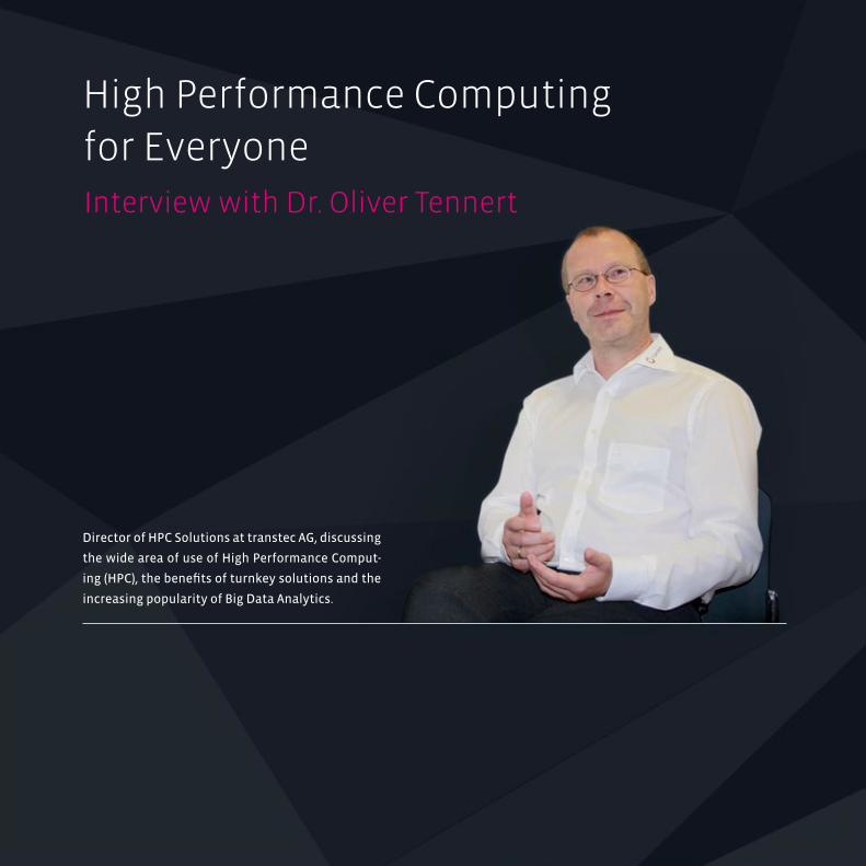
High Performance Computing for Everyone
Director of HPC Solutions at transtec AG, discussing
the wide area of use of High Performance Comput-
ing (HPC), the benefits of turnkey solutions and the
increasing popularity of Big Data Analytics.
Interview with Dr. Oliver Tennert
5
Dr. Tennert, in which industries have you seen an increase in
demand for high performance computing?
From our perspective, it is difficult to differentiate between specific
segments. In general, the high performance computing market is a
globally expanding sector. The US American IT analyst IDC predicts
an annual average growth of approximately 7% over the next 5
years across all sectors even in traditional HPC-dominated indus-
tries such as CAE (Computer-Aided Engineering) and Life Sciences.
For which type of applications is HPC usually deployed? Could
you give us a concrete example of its application?
High performance computing is basically divided into two areas
of application: simulation on the one hand and data analysis on
the other. Take the automotive industry for example.
During the vehicle design and development stage, a great deal of
effort is invested in crash simulations while the number of ma-
terial-intensive crash tests, which used to be performed regular-
ly, have been minimized and are only conducted for verification
purposes.
The analysis of sequenced genome data for hereditary diseases
is a prime example of how data analysis is used effectively – or
from the field of molecular genetics – the measurement of evolu-
tionary relations between different types or the effect of viruses
on the germline.
High performance computing is often criticized under the as-
pect that a HPC installation is far too expensive and complex
for “ordinary” organisations. Which arguments would you use
against these accusations?
[Grinning:] In the past we have sold HPC solutions to many cus-
tomers who would describe themselves as “ordinary” and who
have been extremely satisfied with the results. But you are in
fact right: when using a complex HPC system, it involves hiding
this complexity away from users and administrators. When you
take a look under the hood of a car, you will see that it is also a
complex machine. However drivers do not have to concern them-
selves with features such as transmission technology and ABS
electronics when driving the vehicle.
It is therefore important to ensure you implement a straightfor-
ward and enterprise-ready management and service concept.
transtec offers an intelligent portfolio of service and manage-
ment concepts which are compatible with the paradigms of
“easy to manage” and “easy to use”.
What are the challenges when launching, installing and operat-
ing an HPC system? What should administrators bear in mind to
ensure that the HPC system remains manageable?
When looking for an HPC systems provider, customers should
make sure that the provider has precisely understood their needs
and requirements. This is what differentiates a solutions provider
6
High Performance Computing for Everyone
Interview with Dr. Oliver Tennert
such as transtec from a product-centric hardware supplier or
manufacturer. The optimum sizing of the entire solution and the
above mentioned easy manageability has a direct impact on the
customer’s or user’s productivity.
Once the system has been delivered, customers want to start pro-
ductive operation as soon as possible. transtec provides custom-
ers with turnkey HPC solutions, which means: depending on the
customer’s requirements, our specialists can manage the complete
installation and integration into the customer’s environment.
What is the role of HPC when deploying cloud computing and
big data analyses in large organisations?
When deploying cloud computing, it is important to make a dis-
tinction: that what we today call a “private cloud” is essentially
– leaving technological details to one side – a tried-and-tested
concept in which companies can consolidate and provide ac-
cess to their computing capacities from one central location.
The use of “public cloud” providers such as Amazon has signifi-
cantly dropped in light of previous NSA reports. Security aspects
have always been a serious obstacle for cloud computing and, in
terms of HPC, the situation becomes all the more complicated
for an industrial organisation as high performance computing is
an essential element in the organisation’s value chain. The data
the organisation uses for work is a vital asset and critical to the
company.
Big Data Analytics, in other words the ability to process and analyse
large data volumes, is essentially nothing new. Recently however,
the amount of data has increased at a significantly faster pace
than the computing capacities available.
7
For example, with the use of biochemi-cal methods in “next
generation sequencing”, complete genome sequences can
today be generated and prepared for further analysis
at a far faster rate than ever before. The need for
HPC solutions has recently become increas-
ingly more evident.
While we are on the topic of big data: To
what extent are high-performance, modern
in-memory computing technologies competing
with HPC systems?
This depends on whether you see these technologies in direct
competition to each other! Shared in-memory databases and the
associated computing technologies are innovative concepts for
the particular application, for example real-time analytics or data
mining. We believe that both are contemporary technologies like
many others that enable the analysis of large data volumes in real-
time. From transtec’s point of view, these are HPC technologies
and some of our customers are already using them on HPC
solutions we have provided.
What are expected of today’s supercomputers? What does the
future hold for the HPC segment – and what follows on from
Petaflop and Petabyte?
When we talk of supercomputers, we are referring to the top 500 list
of the fastest computers in the world. “Flop” is used as a measure
of performance, in other words the number of floating point
operations per second. “Tianhe-2” from China currently holds
the number one position with an amazing 34 Petaflops, in other
words 34 billion Flops. However rank 500 scoring 133 Teraflops
(133 million Flops) is still an impressive figure. That is rough-
ly the equivalent of the consolidated performance of
2,000 well configured PCs.
Exabyte follows Petabyte. Over the last
few years it has been widely discussed
on the HPC market what kind of sys-
tem would be needed to manage these
data volumes, particularly in terms of capacity,
power supply and cooling. Significant technology
advancements will expectedly be required before this
type of supercomputer can be produced. Sheer mass alone
will not be able to manage these volumes.
Keyword - security: What is the best way to protect HPC systems
in an age of the NSA scandal and ever increasing cybercrime?
Basically the same applies to HPC systems as it does to company
notebooks and workstations where IT security is concerned:
access by unauthorised parties must be prohibited by deploying
secure IT structures. As described above, enormous volumes of
critical organisation data are stored on an HPC system which is
why efficient data management with effective access control are
essential in HPC environments.
The network connections between the data centre and user
workstations must also be secured on a physical level. This
especially applies when the above-mentioned “private cloud”
scenarios are set up across various locations to allow them to
work together regardless of the particular country or time zone.
„Petabyte
is followed by
Exabyte, although before
that, several technological
jumps need to
take place.“

8
Technology Compass
Table of Contents and Introduction
High Performance Computing ........................................ 10Performance Turns Into Productivity ................................................... 12
Flexible Deployment With xCAT ............................................................... 14
Service and Customer Care From A to Z ............................................. 16
Vector Supercomputing ...................................................... 18The NEC SX Architecture ............................................................................... 20
History of the SX Series.................................................................................. 25
Advanced Cluster Management Made Easy ........... 34Easy-to-use, Complete and Scalable ...................................................... 36
Cloud Bursting With Bright ......................................................................... 44
Intelligent HPC Workload Management ................... 46Moab HPC Suite – Enterprise Edition .................................................... 48
Moab HPC Suite – Grid Option ................................................................... 52
Optimizing Accelerators with Moab HPC Suite .............................. 54
Moab HPC Suite – Application Portal Edition .................................. 58
Moab HPC Suite – Remote Visualization Edition ........................... 60
Remote Visualization and Workflow Optimization ....................................................... 68NICE EnginFrame: A Technical Computing Portal ......................... 70
Desktop Cloud Virtualization .................................................................... 74
Cloud Computing .............................................................................................. 78
NVIDIA GRID .......................................................................................................... 80
Virtual GPU Technology ................................................................................. 82
9
Intel Cluster Ready ................................................................ 84A Quality Standard for HPC Clusters...................................................... 86
Intel Cluster Ready builds HPC Momentum ..................................... 90
The transtec Benchmarking Center ....................................................... 94
Parallel NFS ................................................................................. 96The New Standard for HPC Storage ....................................................... 98
Whats´s New in NFS 4.1? ........................................................................... 100
Panasas HPC Storage ................................................................................... 102
BeeGFS – A Parallel File System ..........................................................116A Parallel File System ................................................................................... 118
NVIDIA GPU Computing .....................................................126What is GPU Computing? .......................................................................... 128
Kepler GK110/210 GPU Computing Architecture ........................ 130
A Quick Refresher on CUDA ...................................................................... 140
Intel Xeon Phi Coprocessor .............................................142The Architecture.............................................................................................. 144
An Outlook on Knights Landing and Omni Path ......................... 152
InfiniBand High-Speed Interconnect ........................156The Architecture.............................................................................................. 158
Intel MPI Library 4.0 Performance ........................................................ 160
Intel Fabric Suite 7 ......................................................................................... 164
Numascale .................................................................................168NumaConnect Background ...................................................................... 170
Technology ......................................................................................................... 172
Redefining Scalable OpenMP and MPI .............................................. 178
Big Data ................................................................................................................ 182
Cache Coherence ............................................................................................ 184
NUMA and ccNUMA ....................................................................................... 186
IBM Platform HPC ..................................................................188Enterprise-Ready Cluster & Workload Management ............... 190
What’s New in IBM Platform LSF 8 ....................................................... 194
IBM Platform MPI 8.1 .................................................................................... 202
General Parallel File System (GPFS) ............................204What is GPFS? ................................................................................................... 206
What´s New in GPFS Version 3.5 ........................................................... 220
Glossary .......................................................................................222

High Performance Computing (HPC) has been with us from the very beginning of the
computer era. High-performance computers were built to solve numerous problems
which the “human computers” could not handle.
The term HPC just hadn’t been coined yet. More important, some of the early principles
have changed fundamentally.
High Performance Computing – Performance Turns Into Productivity
Life
Sci
en
ces
Ris
k A
na
lysi
s S
imu
lati
on
B
ig D
ata
An
aly
tics
H
igh
Pe
rfo
rma
nce
Co
mp
uti
ng
12
Performance Turns Into ProductivityHPC systems in the early days were much different from those
we see today. First, we saw enormous mainframes from large
computer manufacturers, including a proprietary operating
system and job management system. Second, at universities
and research institutes, workstations made inroads and scien-
tists carried out calculations on their dedicated Unix or VMS
workstations. In either case, if you needed more computing
power, you scaled up, i.e. you bought a bigger machine. Today
the term High-Performance Computing has gained a fundamen-
tally new meaning. HPC is now perceived as a way to tackle
complex mathematical, scientific or engineering problems. The
integration of industry standard, “off-the-shelf” server hardware
into HPC clusters facilitates the construction of computer net-
works of such power that one single system could never achieve.
The new paradigm for parallelization is scaling out.
Computer-supported simulations of realistic processes (so-called
Computer Aided Engineering – CAE) has established itself as a third
key pillar in the field of science and research alongside theory
and experimentation. It is nowadays inconceivable that an air-
craft manufacturer or a Formula One racing team would operate
without using simulation software. And scientific calculations,
such as in the fields of astrophysics, medicine, pharmaceuticals
and bio-informatics, will to a large extent be dependent on super-
computers in the future. Software manufacturers long ago rec-
ognized the benefit of high-performance computers based on
powerful standard servers and ported their programs to them
accordingly.
The main advantages of scale-out supercomputers is just that:
they are infinitely scalable, at least in principle. Since they are
based on standard hardware components, such a supercomput-
er can be charged with more power whenever the computational
capacity of the system is not sufficient any more, simply by add-
ing additional nodes of the same kind. A cumbersome switch to a
different technology can be avoided in most cases.
High Performance Computing
Performance Turns Into Productivity
“transtec HPC solutions are meant to provide customers with unpar-
alleled ease-of-management and ease-of-use. Apart from that, decid-
ing for a transtec HPC solution means deciding for the most intensive
customer care and the best service imaginable.”
Dr. Oliver Tennert Director Technology Management & HPC Solutions
S
N
EW
SESW
NENW
tech BOX
13
Variations on the theme: MPP and SMP Parallel computations exist in two major variants today. Ap-
plications running in parallel on multiple compute nodes are
frequently so-called Massively Parallel Processing (MPP) appli-
cations. MPP indicates that the individual processes can each
utilize exclusive memory areas. This means that such jobs are
predestined to be computed in parallel, distributed across the
nodes in a cluster. The individual processes can thus utilize the
separate units of the respective node – especially the RAM, the
CPU power and the disk I/O.
Communication between the individual processes is implement-
ed in a standardized way through the MPI software interface
(Message Passing Interface), which abstracts the underlying
network connections between the nodes from the processes.
However, the MPI standard (current version 2.0) merely requires
source code compatibility, not binary compatibility, so an off-the-
shelf application usually needs specific versions of MPI libraries
in order to run. Examples of MPI implementations are OpenMPI,
MPICH2, MVAPICH2, Intel MPI or – for Windows clusters – MS-MPI.
If the individual processes engage in a large amount of commu-
nication, the response time of the network (latency) becomes im-
portant. Latency in a Gigabit Ethernet or a 10GE network is typi-
cally around 10 µs. High-speed interconnects such as InfiniBand,
reduce latency by a factor of 10 down to as low as 1 µs. Therefore,
high-speed interconnects can greatly speed up total processing.
The other frequently used variant is called SMP applications.
SMP, in this HPC context, stands for Shared Memory Processing.
It involves the use of shared memory areas, the specific imple-
mentation of which is dependent on the choice of the underlying
operating system. Consequently, SMP jobs generally only run on
a single node, where they can in turn be multi-threaded and thus
be parallelized across the number of CPUs per node. For many
HPC applications, both the MPP and SMP variant can be chosen.
Many applications are not inherently suitable for parallel execu-
tion. In such a case, there is no communication between the in-
dividual compute nodes, and therefore no need for a high-speed
network between them; nevertheless, multiple computing jobs
can be run simultaneously and sequentially on each individual
node, depending on the number of CPUs.
In order to ensure optimum computing performance for these
applications, it must be examined how many CPUs and cores de-
liver the optimum performance.
We find applications of this sequential type of work typically in
the fields of data analysis or Monte-Carlo simulations.
BOX
14
High Performance Computing
Flexible Deployment With xCAT
xCAT as a Powerful and Flexible Deployment Tool
xCAT (Extreme Cluster Administration Tool) is an open source
toolkit for the deployment and low-level administration of HPC
cluster environments, small as well as large ones.
xCAT provides simple commands for hardware control, node
discovery, the collection of MAC addresses, and the node deploy-
ment with (diskful) or without local (diskless) installation. The
cluster configuration is stored in a relational database. Node
groups for different operating system images can be defined.
Also, user-specific scripts can be executed automatically at in-
stallation time.
xCAT Provides the Following Low-Level Administrative
Features
� Remote console support
� Parallel remote shell and remote copy commands
� Plugins for various monitoring tools like Ganglia or Nagios
� Hardware control commands for node discovery, collecting
MAC addresses, remote power switching and resetting of
nodes
� Automatic configuration of syslog, remote shell, DNS, DHCP,
and ntp within the cluster
� Extensive documentation and man pages
For cluster monitoring, we install and configure the open source
tool Ganglia or the even more powerful open source solution Na-
gios, according to the customer’s preferences and requirements.
15
Local Installation or Diskless Installation
We offer a diskful or a diskless installation of the cluster nodes.
A diskless installation means the operating system is hosted par-
tially within the main memory, larger parts may or may not be
included via NFS or other means. This approach allows for de-
ploying large amounts of nodes very efficiently, and the cluster
is up and running within a very small timescale. Also, updating
the cluster can be done in a very efficient way. For this, only the
boot image has to be updated, and the nodes have to be reboot-
ed. After this, the nodes run either a new kernel or even a new
operating system. Moreover, with this approach, partitioning the
cluster can also be very efficiently done, either for testing pur-
poses, or for allocating different cluster partitions for different
users or applications.
Development Tools, Middleware, and Applications
According to the application, optimization strategy, or underly-
ing architecture, different compilers lead to code results of very
different performance. Moreover, different, mainly commercial,
applications, require different MPI implementations. And even
when the code is self-developed, developers often prefer one MPI
implementation over another.
According to the customer’s wishes, we install various compilers,
MPI middleware, as well as job management systems like Para-
station, Grid Engine, Torque/Maui, or the very powerful Moab
HPC Suite for the high-level cluster management.
BOX
individual Presalesconsulting
application-,customer-,
site-specificsizing of
HPC solution
burn-in testsof systems
benchmarking of different systems
continualimprovement
software& OS
installation
applicationinstallation
onsitehardwareassembly
integrationinto
customer’senvironment
customertraining
maintenance,support &
managed services
16
High Performance Computing
Services and Customer Care from A to Z
transtec HPC as a ServiceYou will get a range of applications like LS-Dyna, ANSYS,
Gromacs, NAMD etc. from all kinds of areas pre-installed,
integrated into an enterprise-ready cloud and workload
management system, and ready-to run. Do you miss your
application?
Ask us: [email protected]
transtec Platform as a ServiceYou will be provided with dynamically provided compute
nodes for running your individual code. The operating sys-
tem will be pre-installed according to your requirements.
Common Linux distributions like RedHat, CentOS, or SLES
are the standard. Do you need another distribution?
Ask us: [email protected]
transtec Hosting as a ServiceYou will be provided with hosting space inside a profession-
ally managed and secured datacenter where you can have
your machines hosted, managed, maintained, according to
your requirements. Thus, you can build up your own private
cloud. What range of hosting and maintenance services do
you need?
Tell us: [email protected]
HPC @ transtec: Services and Customer Care from A to Ztranstec AG has over 30 years of experience in scientific computing
and is one of the earliest manufacturers of HPC clusters. For nearly a
decade, transtec has delivered highly customized High Performance
clusters based on standard components to academic and industry
customers across Europe with all the high quality standards and the
customer-centric approach that transtec is well known for. Every
transtec HPC solution is more than just a rack full of hardware – it is
a comprehensive solution with everything the HPC user, owner, and
operator need. In the early stages of any customer’s HPC project,
transtec experts provide extensive and detailed consulting to the
customer – they benefit from expertise and experience. Consulting
is followed by benchmarking of different systems with either spe-
cifically crafted customer code or generally accepted benchmarking
routines; this aids customers in sizing and devising the optimal and
detailed HPC configuration. Each and every piece of HPC hardware
that leaves our factory undergoes a burn-in procedure of 24 hours or
Services and Customer Care from A to Z
17
more if necessary. We make sure that any hardware shipped meets
our and our customers’ quality requirements. transtec HPC solutions
are turnkey solutions. By default, a transtec HPC cluster has every-
thing installed and configured – from hardware and operating sys-
tem to important middleware components like cluster management
or developer tools and the customer’s production applications.
Onsite delivery means onsite integration into the customer’s pro-
duction environment, be it establishing network connectivity to the
corporate network, or setting up software and configuration parts.
transtec HPC clusters are ready-to-run systems – we deliver, you
turn the key, the system delivers high performance. Every HPC proj-
ect entails transfer to production: IT operation processes and poli-
cies apply to the new HPC system. Effectively, IT personnel is trained
hands-on, introduced to hardware components and software, with
all operational aspects of configuration management.
transtec services do not stop when the implementation projects
ends. Beyond transfer to production, transtec takes care. transtec
offers a variety of support and service options, tailored to the cus-
tomer’s needs. When you are in need of a new installation, a major
reconfiguration or an update of your solution – transtec is able to
support your staff and, if you lack the resources for maintaining the
cluster yourself, maintain the HPC solution for you.
From Professional Services to Managed Services for daily opera-
tions and required service levels, transtec will be your complete HPC
service and solution provider. transtec’s high standards of perfor-
mance, reliability and dependability assure your productivity and
complete satisfaction. transtec’s offerings of HPC Managed Services
offer customers the possibility of having the complete management
and administration of the HPC cluster managed by transtec service
specialists, in an ITIL compliant way. Moreover, transtec’s HPC on De-
mand services help provide access to HPC resources whenever they
need them, for example, because they do not have the possibility
of owning and running an HPC cluster themselves, due to lacking
infrastructure, know-how, or admin staff.
transtec HPC Cloud ServicesLast but not least transtec’s services portfolio evolves as custom-
ers‘ demands change. Starting this year, transtec is able to provide
HPC Cloud Services. transtec uses a dedicated datacenter to provide
computing power to customers who are in need of more capacity
than they own, which is why this workflow model is sometimes
called computing-on-demand. With these dynamically provided
resources, customers with the possibility to have their jobs run on
HPC nodes in a dedicated datacenter, professionally managed and
secured, and individually customizable. Numerous standard ap-
plications like ANSYS, LS-Dyna, OpenFOAM, as well as lots of codes
like Gromacs, NAMD, VMD, and others are pre-installed, integrated
into an enterprise-ready cloud and workload management environ-
ment, and ready to run.
Alternatively, whenever customers are in need of space for host-
ing their own HPC equipment because they do not have the space
capacity or cooling and power infrastructure themselves, transtec
is also able to provide Hosting Services to those customers who’d
like to have their equipment professionally hosted, maintained, and
managed. Customers can thus build up their own private cloud!
Are you interested in any of transtec’s broad range of HPC related
services? Write us an email to [email protected]. We’ll be happy to
hear from you!

Initially, in the 80s and 90s, the notion of supercomputing was almost a synonym for
vector-computing. And this concept is back now in different flavors. Now almost every
architecture is using SIMD, the acronym for “single instruction multiple data”.
Vector Supercomputing – The NEC SX Architecture
Life
Sci
en
ces
Ris
k A
na
lysi
s S
imu
lati
on
B
ig D
ata
An
aly
tics
H
igh
Pe
rfo
rma
nce
Co
mp
uti
ng
20
History of HPC, and what we learnDuring the last years systems based on x86 architecture domi-
nated the HPC market, with GPUs and many-core systems re-
cently making their inroads. But this period is coming to an end,
and it is again time for a differentiated complementary HPC-
targeted system. NEC will develop such a system.
The Early Days
When did HPC really start? Probably one would think about the
time when Seymour Cray developed high-end machines at CDC
and then started his own company Cray Research, with the first
product being the Cray-1 in 1976. At that time supercomputing was
very special, systems were expensive, and access was extremely
limited for researchers and students. But the business case
was obvious in many fields, scientifically as well as commercially.
These Cray machines were vector-computers, initially featuring
only one CPU, as parallelization was far from being mainstream,
even hardly a matter of research. And code development was
easier than today, a code of 20000 lines was already considered
“complex” at that time, and there were not so many standard
codes and algorithms available anyway. For this reason code-de-
velopment could adapt to any kind of architecture to achieve op-
timal performance.
In 1981 NEC started marketing its first vector supercomputer, the
SX-2, a single-CPU-vector-architecture like the Cray-1. The SX-2
was a milestone, it was the first CPU to exceed one GFlops of peak
performance.
The Attack of the “Killer-Micros”
In the 1990s the situation changed drastically, and what we see
today is a direct consequence. The “killer-micros” took over, new
parallel, later “massively parallel” systems (MPP) were built based
on micro-processor architectures which were predominantly
Vector Supercomputing
The NEC SX Architecture
21
targeted to commercial sectors, or in the case of Intel, AMD or
Motorola to PCs, to products which were successfully invading
the daily life, partially more than even experts had anticipated.
Clearly one could save a lot of cost by using, in the worst case
slightly adapting these CPUs for high-end-systems, and by fo-
cusing investments on other ingredients, like interconnect tech-
nology. At the same time increasingly Linux was adopted and of-
fered a cheap generally available OS platform to allow everybody
to use HPC for a reasonable price.
These systems were cheaper because of two reasons: the develop-
ment of standard CPUs was sponsored by different businesses,
and another expensive part, the memory architecture with many
CPUs addressing the same flat memory space, was replaced by sys-
tems comprised of many distinct so-called nodes, complete sys-
tems by themselves, plus some kind of interconnect technology,
which could also be taken from standard equipment partially.
The impact on the user was the necessity to code for these “dis-
tributed memory systems”. Standards for coding evolved, PVM
and later MPI, plus some proprietary paradigms. MPI is dominat-
ing still today.
In the high-end the special systems were still dominating, be-
cause they had architectural advantages and the codes were run-
ning with very good efficiency on such systems. Most codes were
not parallel at all or at least not well parallelized, let alone on
systems with distributed memory. The skills and experiences to
generate parallel versions of codes were lacking in those compa-
nies selling high-end-machines and also on the customers’ side.
So it took some time for the MPPs to take over. But it was inevi-
table, because this situation, sometimes called “democratization
of HPC”, was positive for both the commercial and the scientific
developments. From that time on researchers and students in
academia and industry got sufficient access to resources they
could not have dreamt of before.
The x86 Dominance
One could dispute whether the x86 architecture is the most
advanced or elegant, undoubtedly it became the dominant
one. It was developed for mass-markets, this was the strate-
gy, and HPC was a side-effect, sponsored by the mass-market.
This worked successfully and the proportion of x86 Linux clus-
ters in the Top500 list increased year by year. Because of the
mass-markets it made sense economically to invest a lot into
the development of LSI technology (large-scale integration).
The related progress, which led to more and more transistors
on the chips and increasing frequencies, helped HPC applica-
tions, which got more, faster and cheaper systems with each
generation. Software did not have to adapt a lot between gen-
erations and the software developments rather focused initial-
ly on the parallelization for distributed memory, later on new
functionalities and features. This worked for quite some years.
Systems of sufficient size to produce relevant results for typical
applications are cheap, and most codes do not really scale to a
level of parallelism to use thousands of processes. Some light-
house projects do, after a lot of development which is not easily
affordable, but the average researcher or student is often com-
pletely satisfied with something between a few and perhaps a
few hundred nodes of a standard Linux cluster.
In the meantime already a typical Intel-based dual-socket-node
of a standard cluster has 24 cores, soon a bit more. So paralleliza-
tion is increasingly important. There is “Moore’s law”, invented by
Gordon E. Moore, a co-founder of the Intel Corporation, in 1965.
Originally it stated that the number of transistors in an integrated
circuit doubles about every 18 months, leading to an exponential
increase. This statement was often misinterpreted that the per-
formance of a CPU would double every 18 months, which is mis-
leading. We observe ever increasing core-counts, the transistors
are just there, so why not? That applications might not be able to

22
use these many cores is another question, in principle the poten-
tial performance is there.
The “standard benchmark” in the HPC-scene is the so-called HPL,
High Performance LINPACK, and the famous Top500 list is built
based on this. This HPL benchmark is only one of three parts of
the original LINPACK benchmark, this is often forgotten! But the
other parts did not show such a good progress in performance,
their scalability is limited, so they could not serve to spawn com-
petition even between nations, which leads to a lot of prestige.
Moreover there are at most a few real codes in the world with
similar characteristics as the HPL. In other words: it does not tell
a lot. This is a highly political situation and probably quite some
money is wasted which would better be invested in brain-ware.
Anyway it is increasingly doubtful that LSI technology will ad-
vance at the same pace in the future. The grid-constant of Silicon
is 5.43 Å. LSI technology is now using 14 nm processes, the Intel
Broadwell generation, which is about 25 times the grid-constant,
and with 7nm LSIs at the long-term horizon. Some scientists as-
sume there is still some room to improve even more, but once
the features on the LSI have a thickness of only a few atoms one
cannot get another factor of ten. Sometimes the impact of some
future “disruptive technology” is claimed …
Another obstacle is the cost to build a chip fab for a new genera-
tion of LSI technology. Certainly there are ways to optimize both
production and cost, and there will be bright ideas, but with cur-
rent generations a fab costs at least many billion $. There have
been ideas of slowing down the innovation cycle on that side to
merely be able to recover the investment.
Memory Bandwidth
For many HPC applications it is not the compute power of the
Vector Supercomputing
The NEC SX Architecture
23
CPU which counts, it is the speed with which the CPU can
exchange data with the memory, the so-called memory band-
width. If it is neglected the CPUs will wait for data, the perfor-
mance will decrease. To describe the balance between CPU
performance and memory bandwidth one often uses the ratio
between operations and the amount of bytes that can be trans-
ferred while they are running, the “byte-per-flop-ratio”. Tradi-
tionally vector machines were always great in this regard, and
this is to continue as far as current plans are known. And this is
the reason why a vector machine can realize a higher fraction
of its theoretical performance on a real application than a sca-
lar machine.
Power Consumption
One other but really overwhelming problem is the increasing
power consumption of systems. Looking at different genera-
tions of Linux clusters one can assume that a dual-socket-node,
depending on how it is equipped with additional features, will
consume between 350 Watt and 400 Watt.
This only slightly varies between different generations, perhaps it
will slightly increase. Even in Europe sites are talking about elec-
tricity budgets in excess of 1 MWatt, even beyond 10 MWatts. One
also has to cool the system, which adds something like 10-30%
to the electricity cost! The cost to run such a system over 5 years
will be in the same order of magnitude as the purchase price!
The power consumption will grow with the frequency of the CPU,
is the dominant reason why frequencies are stagnating, if not de-
creasing between product generations. There are more cores, but
individual cores of an architecture are getting slower, not faster!
This has to be compensated on the application side by increased
scalability, which is not always easy to achieve. In the past us-
ers easily got a higher performance for almost every application
with each new generation, this is no longer the case.
Architecture Development
So the basic facts clearly indicate limitations of the LSI technology
and they are known since quite some time. Consequently this
leads to attempts to get additional performance by other means.
And the developments in the market clearly indicate that high-
end users are willing to consider the adaptation of codes.
To utilize available transistors CPUs with more complex func-
tionality are designed, utilizing SIMD instructions or providing
more operations per cycle than just an add and a multiply. SIMD
is “Single Instruction Multiple Data”. Initially at Intel the SIMD-in-
structions provided two results in 64-bit-precision per cycle rath-
er than one, in the meantime with AVX it is even four, on Xeon Phi
already eight.
This makes a lot of sense. The electricity consumed by the “ad-
ministration” of the operations, code fetch and decode, configu-
ration of paths on the CPU etc. is a significant portion of the pow-
er consumption. If the energy is used not only for one operation
but for two or even four, the energy per operation is obviously
reduced.
In essence and in order to overcome the performance-bottleneck
the architectures developed into the direction which to a larger
extent was already realized in the vector-supercomputers dec-
ades ago!
There is almost no architecture left without such features. But
SIMD-operations require application code to be vectorized. Be-
fore code developments and programming paradigms did not
care for fine-grain data-parallelism, which is the basis of appli-
cability of SIMD. Thus vector-machines could not show their
strength, on scalar code they cannot beat a scalar CPU. But strictly
speaking, there is no scalar CPU left, standard x86-systems do not
achieve their optimal performance on purely scalar code as well!
24
Alternative Architectures?
During recent years GPUs and many-core architectures are in-
creasingly used in the HPC market. Although these systems are
somewhat diverse in detail, in any case the degree of parallelism
needed is much higher than in standard CPUs. This points into
the same direction, a low-level parallelism is used to address the
bottlenecks. In the case of Nvidia GPUs the individual so-called
CUDA cores, relatively simple entities, are steered by a more
complex central processor, realizing a high level of SIMD paral-
lelism. In the case of Xeon Phi the individual cores are also less
powerful, but they are used in parallel using coding paradigms
which operate on the level of loop nests, an approach which was
already used on vector supercomputers during the 1980s!
So these alternative architectures not only go into the same
direction, the utilization of fine-grain parallelism, they also in-
dicate that coding styles which suite real vector machines will
dominate the future software developments. Note that at last
some of these systems have an economic backing by mass mar-
kets, gaming!
Vector Supercomputing
The NEC SX Architecture
S
N
EW
SESW
NENW
tech BOX
25
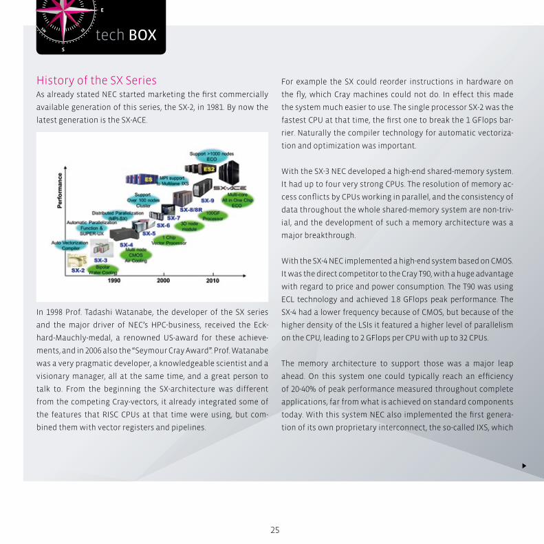
History of the SX SeriesAs already stated NEC started marketing the first commercially
available generation of this series, the SX-2, in 1981. By now the
latest generation is the SX-ACE.
In 1998 Prof. Tadashi Watanabe, the developer of the SX series
and the major driver of NEC’s HPC-business, received the Eck-
hard-Mauchly-medal, a renowned US-award for these achieve-
ments, and in 2006 also the “Seymour Cray Award”. Prof. Watanabe
was a very pragmatic developer, a knowledgeable scientist and a
visionary manager, all at the same time, and a great person to
talk to. From the beginning the SX-architecture was different
from the competing Cray-vectors, it already integrated some of
the features that RISC CPUs at that time were using, but com-
bined them with vector registers and pipelines.
For example the SX could reorder instructions in hardware on
the fly, which Cray machines could not do. In effect this made
the system much easier to use. The single processor SX-2 was the
fastest CPU at that time, the first one to break the 1 GFlops bar-
rier. Naturally the compiler technology for automatic vectoriza-
tion and optimization was important.
With the SX-3 NEC developed a high-end shared-memory system.
It had up to four very strong CPUs. The resolution of memory ac-
cess conflicts by CPUs working in parallel, and the consistency of
data throughout the whole shared-memory system are non-triv-
ial, and the development of such a memory architecture was a
major breakthrough.
With the SX-4 NEC implemented a high-end system based on CMOS.
It was the direct competitor to the Cray T90, with a huge advantage
with regard to price and power consumption. The T90 was using
ECL technology and achieved 1.8 GFlops peak performance. The
SX-4 had a lower frequency because of CMOS, but because of the
higher density of the LSIs it featured a higher level of parallelism
on the CPU, leading to 2 GFlops per CPU with up to 32 CPUs.
The memory architecture to support those was a major leap
ahead. On this system one could typically reach an efficiency
of 20-40% of peak performance measured throughout complete
applications, far from what is achieved on standard components
today. With this system NEC also implemented the first genera-
tion of its own proprietary interconnect, the so-called IXS, which
26
allowed connecting several of these strong nodes into one highly
powerful system. The IXS featured advanced functions like a
global barrier and some hardware fault-tolerance, things which
other companies tackled years later.
With the SX-5 this direction was continued, it was a very suc-
cessful system pushing the limits of CMOS-based CPUs and mul-
ti-node configurations. At that time slowly the efforts on the us-
ers’ side to parallelize their codes using “message passing”, PVM
and MPI at that time, started to surface, so the need for a huge
shared memory system slowly disappeared. Still there were quite
some important codes in the scene which were only parallel us-
ing a shared-memory paradigm, initially “microtasking”, which
was vendor-specific, “autotasking”, NEC and some other vendors
could automatically parallelize code, and later the standard
OpenMP. So there was still sufficient need for a huge a highly ca-
pable shared-memory-system.
But later it became clear that more and more codes could utilize
distributed memory systems, and moreover the memory-archi-
tecture of huge shared memory systems became increasingly
complex and that way costly. A memory is made of “banks”, in-
dividual pieces of memory which are used in parallel. In order
to provide the data at the necessary speed for a CPU a certain
minimum amount of banks per CPU is required, because a bank
needs some cycles to recover after every access. Consequently
the number of banks had to scale with the number of CPUs, so
that the complexity of the network connecting CPUs and banks
was growing with the square of the number of CPUs. And if the
CPUs became stronger they needed more banks, which made it
even worse. So this concept became too expensive.
Vector Supercomputing
History of the SX Series
27
At the same time NEC had a lot of experience in mixing MPI- and
OpenMP parallelization in applications, and it turned out that for
the very fast CPUs the shared-memory parallelization was typi-
cally not really efficient for more than four or eight threads. So
the concept was adapted accordingly, which lead to the SX-6 and
the famous Earth-Simulator, which kept the #1-spot of the Top500
for some years.
The Earth Simulator was a different machine, but based
on the same technology level and architecture as the SX-6.
These systems were the first implementation ever of a vector-CPU
on one single chip. The CPU by itself was not the challenge, but
the interface to the memory to support the bandwidth needed
for this chip, basically the “pins”. This kind of packaging tech-
no-logy was always a strong point in NEC’s technology portfolio.
The SX-7 was a somewhat special machine, it was based on the SX-6
technology level, but featured 32 CPUs on one shared memory.
The SX-8 then was a new implementation again with some ad-
vanced features which directly addressed the necessities of cer-
tain code-structures frequently encountered in applications. The
communication between the world-wide organization of appli-
cation-analysts and the hard- and software developers in Japan
had proven very fruitful, the SX-8 was very successful in the market.
With the SX-9 the number of CPUs per node was pushed up again
to 16 because of certain demands in the market. Just as an in-
dication for the complexity of the memory architecture: the
system had 16384 banks! The peak-performance of one node was
16 TFlops.
Keep in mind that the efficiency achieved on real applications
was still in the range of 10% in bad cases, up to 20% or even more,
depending on the code. One should not compare this peak perfor-
mance with some standard chip today, this would be misleading.
The Current Product: SX-ACEIn November 2014 NEC announced the next generation of the
SX-vector-product, the SX-ACE. Some systems are already in-
stalled and accepted, also in Europe.
The main design target was the reduction of power-consump-
tion per sustained performance, and measurements have prov-
en this has been achieved. In order to do so and in line with the
observation that the shared-memory parallelization with vector
CPUs will be useful on four cores, perhaps eight, but normally
not beyond that, the individual node consists of a single-chip-
four core-processor, which inherits memory-controllers and the
interface to the communication interconnect, a next generation
of the proprietary IXS.
That way a node is a small board, leading to a very compact de-
sign. The complicated network between the memory and the
CPUs, which took about 70% of the power-consumption of an SX-
9, was eliminated. And naturally a new generation of LSI-and PCB
technology also leads to reductions.
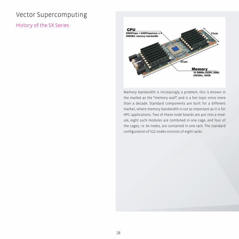
With the memory bandwidth of 256 GB/s this machine realizes
one “byte per flop”, a measure of the balance between the pure
compute power and the memory bandwidth of a chip. In compar-
ison nowadays typical standard processors have in the order of
one eights of this!
28
Memory bandwidth is increasingly a problem, this is known in
the market as the “memory wall”, and is a hot topic since more
than a decade. Standard components are built for a different
market, where memory bandwidth is not as important as it is for
HPC applications. Two of these node boards are put into a mod-
ule, eight such modules are combined in one cage, and four of
the cages, i.e. 64 nodes, are contained in one rack. The standard
configuration of 512 nodes consists of eight racks.
Vector Supercomputing
History of the SX Series
29
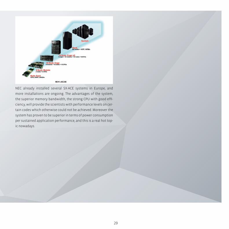
NEC already installed several SX-ACE systems in Europe, and
more installations are ongoing. The advantages of the system,
the superior memory bandwidth, the strong CPU with good effi-
ciency, will provide the scientists with performance levels on cer-
tain codes which otherwise could not be achieved. Moreover the
system has proven to be superior in terms of power consumption
per sustained application performance, and this is a real hot top-
ic nowadays.
S
N
EW
SESW
NENW
tech BOX
do i = 1, n
a(i) = b(i) + c(i)
end do
30
Vector Supercomputing
History of the SX Series
LSI technologies have improved drastically during the last
two decades, but the ever increasing power consumption of
systems now poses serious limitations. Tasks like fetching in-
structions, decoding them or configuring paths on the chip
consume energy, so it makes sense to execute these activities
not for one operation only, but for a set of such operations.
This is meant by SIMD.
Data ParallelismThe underlying structure to enable the usage of SIMD-instruc-
tions is called “data parallelism”. For example the following loop
is data-parallel, the individual loop iterations could be executed
in any arbitrary order, and the results would stay the same:
The complete independence of the loop iterations allows executing
them in parallel, and this is mapped to hardware with SIMD support.
Naturally one could also use other means to parallelize such a
loop, e.g. for a very long loop one could execute chunks of loop
iterations on different processors of a shared-memory machine
using OpenMP. But this will cause overhead, so it will not be effi-
cient for small trip counts, while a SIMD feature in hardware can
deal with such a fine granularity.
As opposed to the example above the following loop, a recursion,
is not data parallel:
do i = 1, n-1
a(i+1) = a(i) + c(i)
end do
31
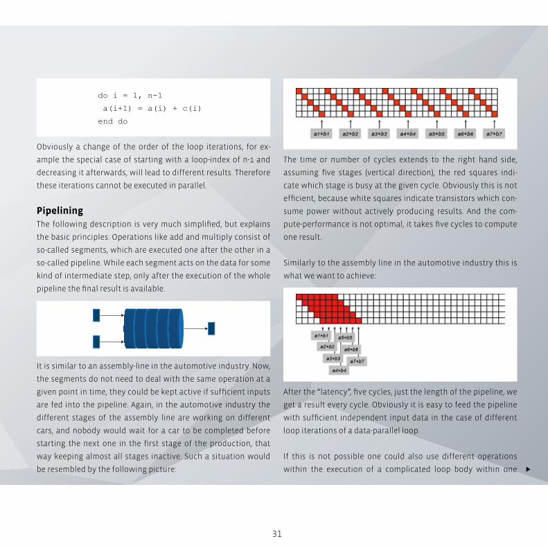
The time or number of cycles extends to the right hand side,
assuming five stages (vertical direction), the red squares indi-
cate which stage is busy at the given cycle. Obviously this is not
efficient, because white squares indicate transistors which con-
sume power without actively producing results. And the com-
pute-performance is not optimal, it takes five cycles to compute
one result.
Similarly to the assembly line in the automotive industry this is
what we want to achieve:
After the “latency”, five cycles, just the length of the pipeline, we
get a result every cycle. Obviously it is easy to feed the pipeline
with sufficient independent input data in the case of different
loop iterations of a data-parallel loop.
If this is not possible one could also use different operations
within the execution of a complicated loop body within one
Obviously a change of the order of the loop iterations, for ex-
ample the special case of starting with a loop-index of n-1 and
decreasing it afterwards, will lead to different results. Therefore
these iterations cannot be executed in parallel.
PipeliningThe following description is very much simplified, but explains
the basic principles: Operations like add and multiply consist of
so-called segments, which are executed one after the other in a
so-called pipeline. While each segment acts on the data for some
kind of intermediate step, only after the execution of the whole
pipeline the final result is available.
It is similar to an assembly-line in the automotive industry. Now,
the segments do not need to deal with the same operation at a
given point in time, they could be kept active if sufficient inputs
are fed into the pipeline. Again, in the automotive industry the
different stages of the assembly line are working on different
cars, and nobody would wait for a car to be completed before
starting the next one in the first stage of the production, that
way keeping almost all stages inactive. Such a situation would
be resembled by the following picture:
32
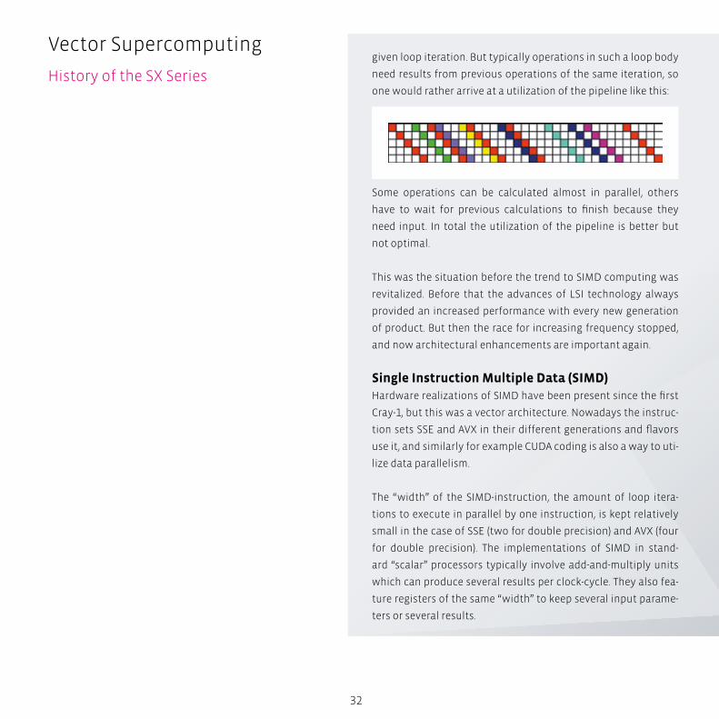
given loop iteration. But typically operations in such a loop body
need results from previous operations of the same iteration, so
one would rather arrive at a utilization of the pipeline like this:
Some operations can be calculated almost in parallel, others
have to wait for previous calculations to finish because they
need input. In total the utilization of the pipeline is better but
not optimal.
This was the situation before the trend to SIMD computing was
revitalized. Before that the advances of LSI technology always
provided an increased performance with every new generation
of product. But then the race for increasing frequency stopped,
and now architectural enhancements are important again.
Single Instruction Multiple Data (SIMD)Hardware realizations of SIMD have been present since the first
Cray-1, but this was a vector architecture. Nowadays the instruc-
tion sets SSE and AVX in their different generations and flavors
use it, and similarly for example CUDA coding is also a way to uti-
lize data parallelism.
The “width” of the SIMD-instruction, the amount of loop itera-
tions to execute in parallel by one instruction, is kept relatively
small in the case of SSE (two for double precision) and AVX (four
for double precision). The implementations of SIMD in stand-
ard “scalar” processors typically involve add-and-multiply units
which can produce several results per clock-cycle. They also fea-
ture registers of the same “width” to keep several input parame-
ters or several results.
Vector Supercomputing
History of the SX Series
33
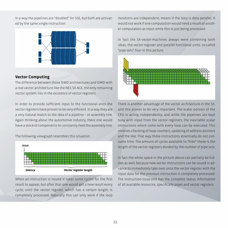
iterations are independent, means if the loop is data parallel. It
would not work if one computation would need a result of anoth-
er computation as input while this is just being processed.
In fact the SX-vector-machines always were combining both
ideas, the vector-register and parallel functional units, so-called
“pipe-sets”, four in this picture:
There is another advantage of the vector architecture in the SX,
and this proves to be very important. The scalar portion of the
CPU is acting independently, and while the pipelines are kept
busy with input from the vector registers, the inevitable scalar
instructions which come with every loop can be executed. This
involves checking of loop counters, updating of address pointers
and the like. That way these instructions essentially do not con-
sume time. The amount of cycles available to “hide” those is the
length of the vector-registers divided by the number of pipe sets.
In fact the white space in the picture above can partially be hid-
den as well, because new vector instructions can be issued in ad-
vance to immediately take over once the vector register with the
input data for the previous instruction is completely processed.
The instruction-issue-unit has the complete status information
of all available resources, specifically pipes and vector registers.
In a way the pipelines are “doubled” for SSE, but both are activat-
ed by the same single instruction:
Vector ComputingThe difference between those SIMD architectures and SIMD with
a real vector architecture like the NEC SX-ACE, the only remaining
vector system, lies in the existence of vector registers.
In order to provide sufficient input to the functional units the
vector registers have proven to be very efficient. In a way they are
a very natural match to the idea of a pipeline – or assembly line.
Again thinking about the automotive industry, there one would
have a stock of components to constantly feed the assembly line.
The following viewgraph resembles this situation:
When an instruction is issued it takes some cycles for the first
result to appear, but after that one would get a new result every
cycle, until the vector register, which has a certain length, is
completely processed. Naturally this can only work if the loop


High Performance Computing (HPC) clusters serve a crucial role at research-intensive
organizations in industries such as aerospace, meteorology, pharmaceuticals, and oil
and gas exploration.
The thing they have in common is a requirement for large-scale computations. Bright’s
solution for HPC puts the power of supercomputing within the reach of just about any
organization.
Advanced Cluster Management Made Easy
Engi
nee
rin
g L
ife
Scie
nce
s A
uto
mo
tive
P
rice
Mo
del
lin
g A
ero
spac
e C
AE
Dat
a A
nal
ytic
s

36
The Bright AdvantageBright Cluster Manager for HPC makes it easy to build and oper-
ate HPC clusters using the server and networking equipment of
your choice, tying them together into a comprehensive, easy to
manage solution.
Bright Cluster Manager for HPC lets customers deploy complete
clusters over bare metal and manage them effectively. It pro-
vides single-pane-of-glass management for the hardware, the
operating system, HPC software, and users. With Bright Cluster
Manager for HPC, system administrators can get clusters up and
running quickly and keep them running reliably throughout their
life cycle – all with the ease and elegance of a fully featured, en-
terprise-grade cluster manager.
Bright Cluster Manager was designed by a group of highly expe-
rienced cluster specialists who perceived the need for a funda-
mental approach to the technical challenges posed by cluster
management. The result is a scalable and flexible architecture,
forming the basis for a cluster management solution that is ex-
tremely easy to install and use, yet is suitable for the largest and
most complex clusters.
Scale clusters to thousands of nodesBright Cluster Manager was designed to scale to thousands of
nodes. It is not dependent on third-party (open source) software
that was not designed for this level of scalability. Many advanced
features for handling scalability and complexity are included:
Management Daemon with Low CPU Overhead
The cluster management daemon (CMDaemon) runs on every
node in the cluster, yet has a very low CPU load – it will not cause
any noticeable slow-down of the applications running on your
cluster.
Because the CMDaemon provides all cluster management func-
tionality, the only additional daemon required is the workload
manager (or queuing system) daemon. For example, no daemons
Advanced Cluster Management Made Easy
Easy-to-use, complete and scalable
The cluster installer takes you through the installation process and offers advanced options such as “Express” and “Remote”.
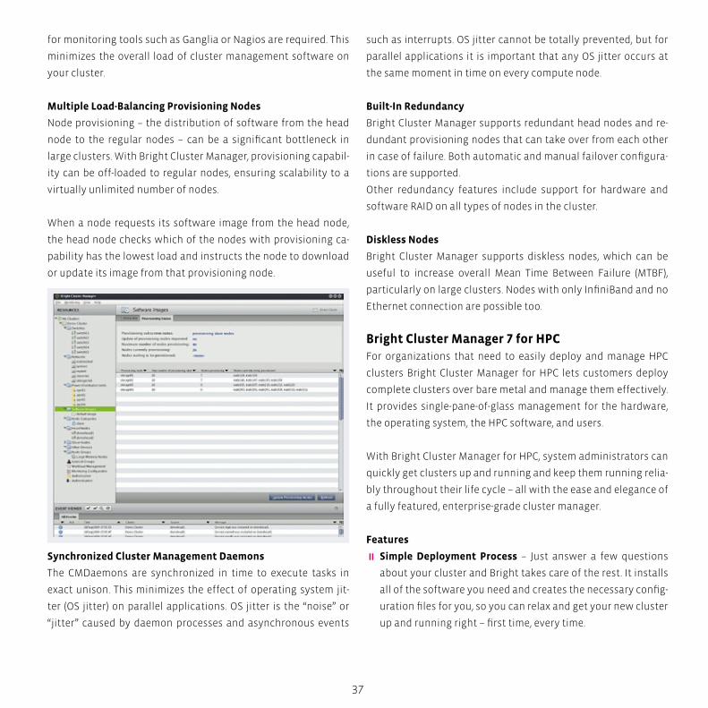
37
for monitoring tools such as Ganglia or Nagios are required. This
minimizes the overall load of cluster management software on
your cluster.
Multiple Load-Balancing Provisioning Nodes
Node provisioning – the distribution of software from the head
node to the regular nodes – can be a significant bottleneck in
large clusters. With Bright Cluster Manager, provisioning capabil-
ity can be off-loaded to regular nodes, ensuring scalability to a
virtually unlimited number of nodes.
When a node requests its software image from the head node,
the head node checks which of the nodes with provisioning ca-
pability has the lowest load and instructs the node to download
or update its image from that provisioning node.
Synchronized Cluster Management Daemons
The CMDaemons are synchronized in time to execute tasks in
exact unison. This minimizes the effect of operating system jit-
ter (OS jitter) on parallel applications. OS jitter is the “noise” or
“jitter” caused by daemon processes and asynchronous events
such as interrupts. OS jitter cannot be totally prevented, but for
parallel applications it is important that any OS jitter occurs at
the same moment in time on every compute node.
Built-In Redundancy
Bright Cluster Manager supports redundant head nodes and re-
dundant provisioning nodes that can take over from each other
in case of failure. Both automatic and manual failover configura-
tions are supported.
Other redundancy features include support for hardware and
software RAID on all types of nodes in the cluster.
Diskless Nodes
Bright Cluster Manager supports diskless nodes, which can be
useful to increase overall Mean Time Between Failure (MTBF),
particularly on large clusters. Nodes with only InfiniBand and no
Ethernet connection are possible too.
Bright Cluster Manager 7 for HPCFor organizations that need to easily deploy and manage HPC
clusters Bright Cluster Manager for HPC lets customers deploy
complete clusters over bare metal and manage them effectively.
It provides single-pane-of-glass management for the hardware,
the operating system, the HPC software, and users.
With Bright Cluster Manager for HPC, system administrators can
quickly get clusters up and running and keep them running relia-
bly throughout their life cycle – all with the ease and elegance of
a fully featured, enterprise-grade cluster manager.
Features
� Simple Deployment Process – Just answer a few questions
about your cluster and Bright takes care of the rest. It installs
all of the software you need and creates the necessary config-
uration files for you, so you can relax and get your new cluster
up and running right – first time, every time.
S
N
EW
SESW
NENW
tech BOX
38
Advanced Cluster Management Made Easy
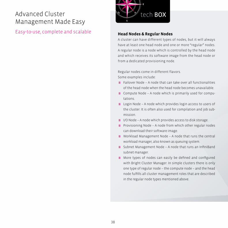
Easy-to-use, complete and scalable Head Nodes & Regular NodesA cluster can have different types of nodes, but it will always
have at least one head node and one or more “regular” nodes.
A regular node is a node which is controlled by the head node
and which receives its software image from the head node or
from a dedicated provisioning node.
Regular nodes come in different flavors.
Some examples include:
� Failover Node – A node that can take over all functionalities
of the head node when the head node becomes unavailable.
� Compute Node – A node which is primarily used for compu-
tations.
� Login Node – A node which provides login access to users of
the cluster. It is often also used for compilation and job sub-
mission.
� I/O Node – A node which provides access to disk storage.
� Provisioning Node – A node from which other regular nodes
can download their software image.
� Workload Management Node – A node that runs the central
workload manager, also known as queuing system.
� Subnet Management Node – A node that runs an InfiniBand
subnet manager.
� More types of nodes can easily be defined and configured
with Bright Cluster Manager. In simple clusters there is only
one type of regular node – the compute node – and the head
node fulfills all cluster management roles that are described
in the regular node types mentioned above.
39
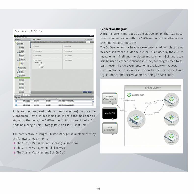
All types of nodes (head nodes and regular nodes) run the same
CMDaemon. However, depending on the role that has been as-
signed to the node, the CMDaemon fulfills different tasks. This
node has a ‘Login Role’, ‘Storage Role’ and ‘PBS Client Role’.
The architecture of Bright Cluster Manager is implemented by
the following key elements:
� The Cluster Management Daemon (CMDaemon)
� The Cluster Management Shell (CMSH)
� The Cluster Management GUI (CMGUI)
Connection Diagram
A Bright cluster is managed by the CMDaemon on the head node,
which communicates with the CMDaemons on the other nodes
over encrypted connections.
The CMDaemon on the head node exposes an API which can also
be accessed from outside the cluster. This is used by the cluster
management Shell and the cluster management GUI, but it can
also be used by other applications if they are programmed to ac-
cess the API. The API documentation is available on request.
The diagram below shows a cluster with one head node, three
regular nodes and the CMDaemon running on each node.
Elements of the Architecture
40
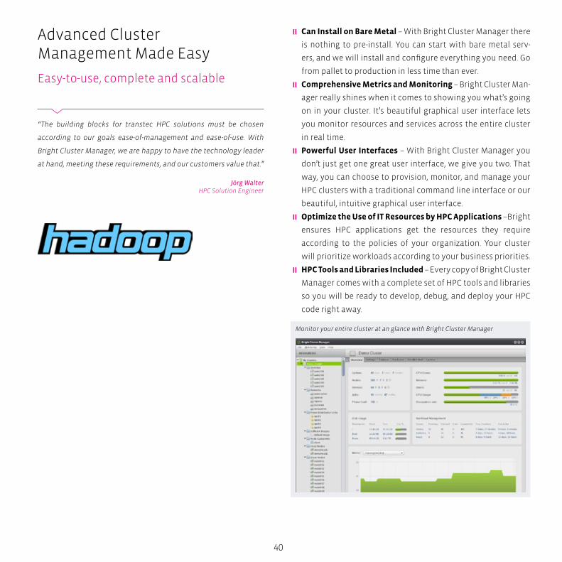
� Can Install on Bare Metal – With Bright Cluster Manager there
is nothing to pre-install. You can start with bare metal serv-
ers, and we will install and configure everything you need. Go
from pallet to production in less time than ever.
� Comprehensive Metrics and Monitoring – Bright Cluster Man-
ager really shines when it comes to showing you what’s going
on in your cluster. It’s beautiful graphical user interface lets
you monitor resources and services across the entire cluster
in real time.
� Powerful User Interfaces – With Bright Cluster Manager you
don’t just get one great user interface, we give you two. That
way, you can choose to provision, monitor, and manage your
HPC clusters with a traditional command line interface or our
beautiful, intuitive graphical user interface.
� Optimize the Use of IT Resources by HPC Applications –Bright
ensures HPC applications get the resources they require
according to the policies of your organization. Your cluster
will prioritize workloads according to your business priorities.
� HPC Tools and Libraries Included – Every copy of Bright Cluster
Manager comes with a complete set of HPC tools and libraries
so you will be ready to develop, debug, and deploy your HPC
code right away.
Advanced Cluster Management Made Easy
Easy-to-use, complete and scalable
“The building blocks for transtec HPC solutions must be chosen
according to our goals ease-of-management and ease-of-use. With
Bright Cluster Manager, we are happy to have the technology leader
at hand, meeting these requirements, and our customers value that.”
Jörg WalterHPC Solution Engineer
Monitor your entire cluster at an glance with Bright Cluster Manager
41
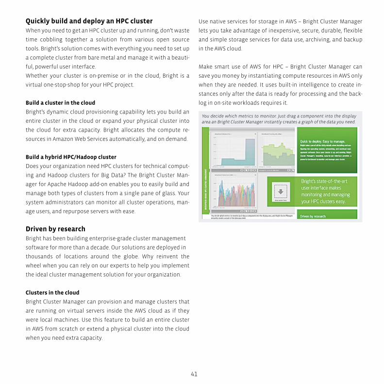
Quickly build and deploy an HPC cluster When you need to get an HPC cluster up and running, don’t waste
time cobbling together a solution from various open source
tools. Bright’s solution comes with everything you need to set up
a complete cluster from bare metal and manage it with a beauti-
ful, powerful user interface.
Whether your cluster is on-premise or in the cloud, Bright is a
virtual one-stop-shop for your HPC project.
Build a cluster in the cloud
Bright’s dynamic cloud provisioning capability lets you build an
entire cluster in the cloud or expand your physical cluster into
the cloud for extra capacity. Bright allocates the compute re-
sources in Amazon Web Services automatically, and on demand.
Build a hybrid HPC/Hadoop cluster
Does your organization need HPC clusters for technical comput-
ing and Hadoop clusters for Big Data? The Bright Cluster Man-
ager for Apache Hadoop add-on enables you to easily build and
manage both types of clusters from a single pane of glass. Your
system administrators can monitor all cluster operations, man-
age users, and repurpose servers with ease.
Driven by researchBright has been building enterprise-grade cluster management
software for more than a decade. Our solutions are deployed in
thousands of locations around the globe. Why reinvent the
wheel when you can rely on our experts to help you implement
the ideal cluster management solution for your organization.
Clusters in the cloud
Bright Cluster Manager can provision and manage clusters that
are running on virtual servers inside the AWS cloud as if they
were local machines. Use this feature to build an entire cluster
in AWS from scratch or extend a physical cluster into the cloud
when you need extra capacity.
Use native services for storage in AWS – Bright Cluster Manager
lets you take advantage of inexpensive, secure, durable, flexible
and simple storage services for data use, archiving, and backup
in the AWS cloud.
Make smart use of AWS for HPC – Bright Cluster Manager can
save you money by instantiating compute resources in AWS only
when they are needed. It uses built-in intelligence to create in-
stances only after the data is ready for processing and the back-
log in on-site workloads requires it.
You decide which metrics to monitor. Just drag a component into the display area an Bright Cluster Manager instantly creates a graph of the data you need.

BOX
42
Advanced Cluster Management Made Easy
Easy-to-use, complete and scalable High performance meets efficiencyInitially, massively parallel systems constitute a challenge to
both administrators and users. They are complex beasts. Anyone
building HPC clusters will need to tame the beast, master the
complexity and present users and administrators with an easy-
to-use, easy-to-manage system landscape.
Leading HPC solution providers such as transtec achieve this
goal. They hide the complexity of HPC under the hood and match
high performance with efficiency and ease-of-use for both users
and administrators. The “P” in “HPC” gains a double meaning:
“Performance” plus “Productivity”.
Cluster and workload management software like Moab HPC
Suite, Bright Cluster Manager or Intel Fabric Suite provide the
means to master and hide the inherent complexity of HPC sys-
tems. For administrators and users, HPC clusters are presented
as single, large machines, with many different tuning parame-
ters. The software also provides a unified view of existing clus-
ters whenever unified management is added as a requirement by
the customer at any point in time after the first installation. Thus,
daily routine tasks such as job management, user management,
queue partitioning and management, can be performed easily
with either graphical or web-based tools, without any advanced
scripting skills or technical expertise required from the adminis-
trator or user.
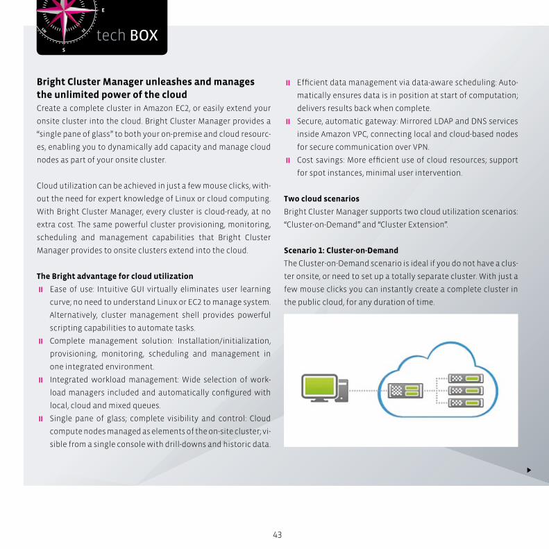
S
N
EW
SESW
NENW
tech BOX
43
Bright Cluster Manager unleashes and manages the unlimited power of the cloudCreate a complete cluster in Amazon EC2, or easily extend your
onsite cluster into the cloud. Bright Cluster Manager provides a
“single pane of glass” to both your on-premise and cloud resourc-
es, enabling you to dynamically add capacity and manage cloud
nodes as part of your onsite cluster.
Cloud utilization can be achieved in just a few mouse clicks, with-
out the need for expert knowledge of Linux or cloud computing.
With Bright Cluster Manager, every cluster is cloud-ready, at no
extra cost. The same powerful cluster provisioning, monitoring,
scheduling and management capabilities that Bright Cluster
Manager provides to onsite clusters extend into the cloud.
The Bright advantage for cloud utilization
� Ease of use: Intuitive GUI virtually eliminates user learning
curve; no need to understand Linux or EC2 to manage system.
Alternatively, cluster management shell provides powerful
scripting capabilities to automate tasks.
� Complete management solution: Installation/initialization,
provisioning, monitoring, scheduling and management in
one integrated environment.
� Integrated workload management: Wide selection of work-
load managers included and automatically configured with
local, cloud and mixed queues.
� Single pane of glass; complete visibility and control: Cloud
compute nodes managed as elements of the on-site cluster; vi-
sible from a single console with drill-downs and historic data.
� Efficient data management via data-aware scheduling: Auto-
matically ensures data is in position at start of computation;
delivers results back when complete.
� Secure, automatic gateway: Mirrored LDAP and DNS services
inside Amazon VPC, connecting local and cloud-based nodes
for secure communication over VPN.
� Cost savings: More efficient use of cloud resources; support
for spot instances, minimal user intervention.
Two cloud scenarios
Bright Cluster Manager supports two cloud utilization scenarios:
“Cluster-on-Demand” and “Cluster Extension”.
Scenario 1: Cluster-on-Demand
The Cluster-on-Demand scenario is ideal if you do not have a clus-
ter onsite, or need to set up a totally separate cluster. With just a
few mouse clicks you can instantly create a complete cluster in
the public cloud, for any duration of time.
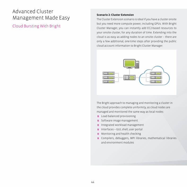
44
Advanced Cluster Management Made Easy
Cloud Bursting With Bright
Scenario 2: Cluster Extension
The Cluster Extension scenario is ideal if you have a cluster onsite
but you need more compute power, including GPUs. With Bright
Cluster Manager, you can instantly add EC2-based resources to
your onsite cluster, for any duration of time. Extending into the
cloud is as easy as adding nodes to an onsite cluster – there are
only a few additional, one-time steps after providing the public
cloud account information to Bright Cluster Manager.
The Bright approach to managing and monitoring a cluster in
the cloud provides complete uniformity, as cloud nodes are
managed and monitored the same way as local nodes:
� Load-balanced provisioning
� Software image management
� Integrated workload management
� Interfaces – GUI, shell, user portal
� Monitoring and health checking
� Compilers, debuggers, MPI libraries, mathematical libraries
and environment modules

Bright Computing
45
Bright Cluster Manager also provides additional features that are
unique to the cloud.
Amazon spot instance support – Bright Cluster Manager enables
users to take advantage of the cost savings offered by Amazon’s
spot instances. Users can specify the use of spot instances, and
Bright will automatically schedule as available, reducing the cost
to compute without the need to monitor spot prices and sched-
ule manually.
Hardware Virtual Machine (HVM) – Bright Cluster Manager auto-
matically initializes all Amazon instance types, including Cluster
Compute and Cluster GPU instances that rely on HVM virtualization.
Amazon VPC – Bright supports Amazon VPC setups which allows
compute nodes in EC2 to be placed in an isolated network, there-
by separating them from the outside world. It is even possible to
route part of a local corporate IP network to a VPC subnet in EC2,
so that local nodes and nodes in EC2 can communicate easily.
Data-aware scheduling – Data-aware scheduling ensures that
input data is automatically transferred to the cloud and made
accessible just prior to the job starting, and that the output data
is automatically transferred back. There is no need to wait for the
data to load prior to submitting jobs (delaying entry into the job
queue), nor any risk of starting the job before the data transfer is
complete (crashing the job). Users submit their jobs, and Bright’s
data-aware scheduling does the rest.
Bright Cluster Manager provides the choice:
“To Cloud, or Not to Cloud”
Not all workloads are suitable for the cloud. The ideal situation
for most organizations is to have the ability to choose between
onsite clusters for jobs that require low latency communication,
complex I/O or sensitive data; and cloud clusters for many other
types of jobs.
Bright Cluster Manager delivers the best of both worlds: a pow-
erful management solution for local and cloud clusters, with
the ability to easily extend local clusters into the cloud without
compromising provisioning, monitoring or managing the cloud
resources.
One or more cloud nodes can be configured under the Cloud Settings tab.

While all HPC systems face challenges in workload demand, workflow constraints,
resource complexity, and system scale, enterprise HPC systems face more stringent
challenges and expectations.
Enterprise HPC systems must meet mission-critical and priority HPC workload
demands for commercial businesses, business-oriented research, and academic
organizations
Intelligent HPCWorkload Management
47H
igh
Tro
uh
pu
t C
om
pu
tin
g
CA
D B
ig D
ata
An
aly
tics
S
imu
lati
on
Ae
rosp
ace
A
uto
mo
tive
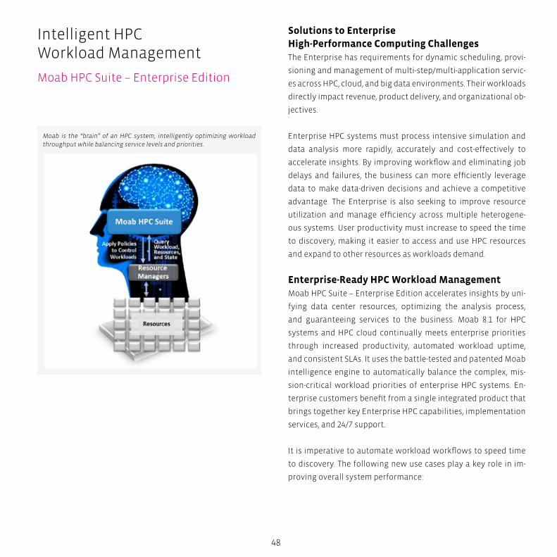
48
Solutions to Enterprise High-Performance Computing ChallengesThe Enterprise has requirements for dynamic scheduling, provi-
sioning and management of multi-step/multi-application servic-
es across HPC, cloud, and big data environments. Their workloads
directly impact revenue, product delivery, and organizational ob-
jectives.
Enterprise HPC systems must process intensive simulation and
data analysis more rapidly, accurately and cost-effectively to
accelerate insights. By improving workflow and eliminating job
delays and failures, the business can more efficiently leverage
data to make data-driven decisions and achieve a competitive
advantage. The Enterprise is also seeking to improve resource
utilization and manage efficiency across multiple heterogene-
ous systems. User productivity must increase to speed the time
to discovery, making it easier to access and use HPC resources
and expand to other resources as workloads demand.
Enterprise-Ready HPC Workload ManagementMoab HPC Suite – Enterprise Edition accelerates insights by uni-
fying data center resources, optimizing the analysis process,
and guaranteeing services to the business. Moab 8.1 for HPC
systems and HPC cloud continually meets enterprise priorities
through increased productivity, automated workload uptime,
and consistent SLAs. It uses the battle-tested and patented Moab
intelligence engine to automatically balance the complex, mis-
sion-critical workload priorities of enterprise HPC systems. En-
terprise customers benefit from a single integrated product that
brings together key Enterprise HPC capabilities, implementation
services, and 24/7 support.
It is imperative to automate workload workflows to speed time
to discovery. The following new use cases play a key role in im-
proving overall system performance:
Intelligent HPC Workload Management
Moab HPC Suite – Enterprise Edition
Moab is the “brain” of an HPC system, intelligently optimizing workload throughput while balancing service levels and priorities.
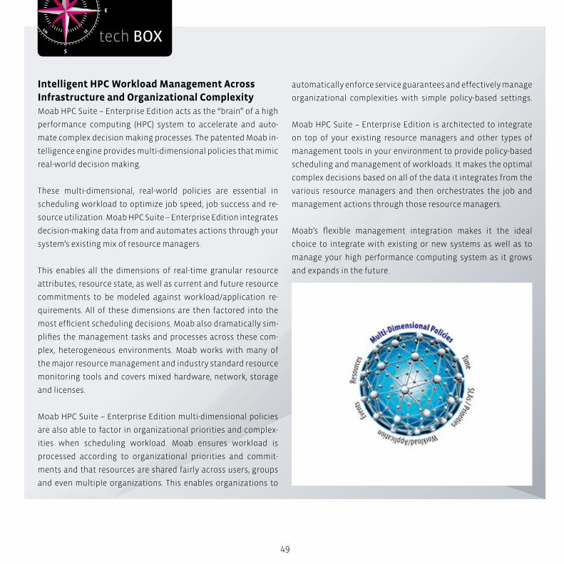
S
N
EW
SESW
NENW
tech BOX
49
Intelligent HPC Workload Management Across Infrastructure and Organizational ComplexityMoab HPC Suite – Enterprise Edition acts as the “brain” of a high
performance computing (HPC) system to accelerate and auto-
mate complex decision making processes. The patented Moab in-
telligence engine provides multi-dimensional policies that mimic
real-world decision making.
These multi-dimensional, real-world policies are essential in
scheduling workload to optimize job speed, job success and re-
source utilization. Moab HPC Suite – Enterprise Edition integrates
decision-making data from and automates actions through your
system’s existing mix of resource managers.
This enables all the dimensions of real-time granular resource
attributes, resource state, as well as current and future resource
commitments to be modeled against workload/application re-
quirements. All of these dimensions are then factored into the
most efficient scheduling decisions. Moab also dramatically sim-
plifies the management tasks and processes across these com-
plex, heterogeneous environments. Moab works with many of
the major resource management and industry standard resource
monitoring tools and covers mixed hardware, network, storage
and licenses.
Moab HPC Suite – Enterprise Edition multi-dimensional policies
are also able to factor in organizational priorities and complex-
ities when scheduling workload. Moab ensures workload is
processed according to organizational priorities and commit-
ments and that resources are shared fairly across users, groups
and even multiple organizations. This enables organizations to
automatically enforce service guarantees and effectively manage
organizational complexities with simple policy-based settings.
Moab HPC Suite – Enterprise Edition is architected to integrate
on top of your existing resource managers and other types of
management tools in your environment to provide policy-based
scheduling and management of workloads. It makes the optimal
complex decisions based on all of the data it integrates from the
various resource managers and then orchestrates the job and
management actions through those resource managers.
Moab’s flexible management integration makes it the ideal
choice to integrate with existing or new systems as well as to
manage your high performance computing system as it grows
and expands in the future.

50
� Elastic Computing – unifies data center resources by assisting
the business management resource expansion through burst-
ing to private/public clouds and other data center resources
utilizing OpenStack as a common platform
� Performance and Scale – optimizes the analysis process by
dramatically increasing TORQUE and Moab throughput and
scalability across the board
� Tighter cooperation between Moab and Torque – harmoniz-
ing these key structures to reduce overhead and improve
communication between the HPC scheduler and the re-
source manager(s)
� More Parallelization – increasing the decoupling of Moab
and TORQUE’s network communication so Moab is less
dependent on TORQUE’S responsiveness, resulting in a 2x
speed improvement and shortening the duration of the av-
erage scheduling iteration in half
� Accounting Improvements – allowing toggling between
multiple modes of accounting with varying levels of en-
forcement, providing greater flexibility beyond strict allo-
cation options. Additionally, new up-to-date accounting
balances provide real-time insights into usage tracking.
� Viewpoint Admin Portal – guarantees services to the busi-
ness by allowing admins to simplify administrative reporting,
workload status tracking, and job resource viewing
Accelerate InsightsMoab HPC Suite – Enterprise Edition accelerates insights by in-
creasing overall system, user and administrator productivity,
achieving more accurate results that are delivered faster and at
a lower cost from HPC resources. Moab provides the scalability,
90-99 percent utilization, and simple job submission required to
maximize productivity. This ultimately speeds the time to discov-
ery, aiding the enterprise in achieving a competitive advantage
due to its HPC system. Enterprise use cases and capabilities in-
clude the following:
Intelligent HPC Workload Management
Moab HPC Suite – Enterprise Edition
“With Moab HPC Suite, we can meet very demanding customers’
requirements as regards unified management of heterogeneous
cluster environments, grid management, and provide them with flex-
ible and powerful configuration and reporting options. Our custom-
ers value that highly.”
Thomas GebertHPC Solution Architect

51
� OpenStack integration to offer virtual and physical resource
provisioning for IaaS and PaaS
� Performance boost to achieve 3x improvement in overall opti-
mization performance
� Advanced workflow data staging to enable improved cluster
utilization, multiple transfer methods, and new transfer types
� Advanced power management with clock frequency control
and additional power state options, reducing energy costs by
15-30 percent
�Workload-optimized allocation policies and provisioning to
get more results out of existing heterogeneous resources and
reduce costs, including topology-based allocation
� Unify workload management across heterogeneous clusters
by managing them as one cluster, maximizing resource availa-
bility and administration efficiency
� Optimized, intelligent scheduling packs workloads and back-
fills around priority jobs and reservations while balancing
SLAs to efficiently use all available resources
� Optimized scheduling and management of accelerators, both
Intel Xeon Phi and GPGPUs, for jobs to maximize their utiliza-
tion and effectiveness
� Simplified job submission and management with advanced
job arrays and templates
� Showback or chargeback for pay-for-use so actual resource
usage is tracked with flexible chargeback rates and reporting
by user, department, cost center, or cluster
� Multi-cluster grid capabilities manage and share workload
across multiple remote clusters to meet growing workload
demand or surges
Guarantee Services to the BusinessJob and resource failures in enterprise HPC systems lead to de-
layed results, missed organizational opportunities, and missed
objectives. Moab HPC Suite – Enterprise Edition intelligently
automates workload and resource uptime in the HPC system to
ensure that workloads complete successfully and reliably, avoid
failures, and guarantee services are delivered to the business.
52
The Enterprise benefits from these features:
� Intelligent resource placement prevents job failures with
granular resource modeling, meeting workload requirements
and avoiding at-risk resources
� Auto-response to failures and events with configurable ac-
tions to pre-failure conditions, amber alerts, or other metrics
and monitors
�Workload-aware future maintenance scheduling that helps
maintain a stable HPC system without disrupting workload
productivity
� Real-world expertise for fast time-to-value and system uptime
with included implementation, training and 24/7 support re-
mote services
Auto SLA EnforcementMoab HPC Suite – Enterprise Edition uses the powerful Moab in-
telligence engine to optimally schedule and dynamically adjust
workload to consistently meet service level agreements (SLAs),
guarantees, or business priorities. This automatically ensures
that the right workloads are completed at the optimal times,
taking into account the complex number of using departments,
priorities, and SLAs to be balanced. Moab provides the following
benefits:
� Usage accounting and budget enforcement that schedules
resources and reports on usage in line with resource sharing
agreements and precise budgets (includes usage limits, usage
reports, auto budget management, and dynamic fair share
policies)
� SLA and priority policies that make sure the highest priority
workloads are processed first (includes Quality of Service and
hierarchical priority weighting)
� Continuous plus future scheduling that ensures priorities and
guarantees are proactively met as conditions and workload
changes (i.e. future reservations, pre-emption)
Intelligent HPC Workload Management
Moab HPC Suite – Grid Option

53
Grid- and Cloud-Ready Workload ManagementThe benefits of a traditional HPC environment can be extended
to more efficiently manage and meet workload demand with
the multi-cluster grid and HPC cloud management capabilities in
Moab HPC Suite – Enterprise Edition. It allows you to:
� Self-service job submission portal enables users to easily sub-
mit and track HPC cloud jobs at any time from any location
with little training required
� Pay-for-use show back or chargeback so actual resource usage
is tracked with flexible chargeback rates reporting by user, de-
partment, cost center, or cluster
� On-demand workload-optimized node provisioning dynami-
cally provisions nodes based on policies, to better meet work-
load needs.
� Manage and share workload across multiple remote clusters
to meet growing workload demand or surges by adding on the
Moab HPC Suite – Grid Option.
S
N
EW
SESW
NENW
tech BOX
54
Choose the Moab HPC Suite That’s Right for YouThis following chart provides a high-level comparison of the dif-
ference in key use cases and capabilities that are enabled be-
tween the different editions of Moab HPC Suite to intelligently
manage and optimize HPC workload efficiency. Customers can
use this chart to help determine which edition will best address
their HPC workload management challenges, maximize their
workload and resource productivity, and help them meet their
service level performance goals. To explore any use cases or ca-
pability compared in the chart further, see the HPC Workload
Management Use Cases.
� Basic Edition is best for static, non-dynamic basic clusters of
all sizes who want to optimize workload throughput and uti-
lization while balancing priorities
� Enterprise Edition is best for large clusters with dynamic,
mission-critical workloads and complex service levels and
priorities to balance. It is also for organizations who want to
integrate or who require HPC Cloud capabilities for their HPC
cluster systems. Enterprise Edition provides additional uses
cases these organizations need such as: Accounting for us-
age of cluster resources for usage budgeting and pay-for-use
showback or chargeback
� Workload optimized node provisioning
� Heterogeneous, multi-cluster workload management
� Workload-aware power management
Intelligent HPC Workload Management
Optimizing Accelerators with
Moab HPC Suit
55
� Application Portal Edition is suited for customers who need an
application-centric job submission experience to simplify and
extend high performance computing to more users without re-
quiring specialized HPC training. It provides all the benefits of
the Enterprise Edition plus meeting these requirements with
a technical computing application portal that supports most
common applications in manufacturing, oil & gas, life sciences,
academic, government and other industries.
� Remote Visualization Edition is suited for customers with
many users, internally or external to their organization, of
3D/CAE/CAD and other visualization applications who want
to reduce the hardware, networking and management costs
of running their visualization workloads. This edition also
provides the added benefits of improved workforce produc-
tivity and collaboration while optimizing the utilization and
guaranteeing shared resource access for users moving from
technical workstations to more efficient shared resources in
a technical compute cloud. It provides all the benefits of the
Enterprise Edition plus providing these additional capabili-
ties and benefits.
BOX
56
transtec HPC solutions are designed for maximum flexibility
and ease of management. We not only offer our customers
the most powerful and flexible cluster management solution
out there, but also provide them with customized setup and
sitespecific configuration. Whether a customer needs a dynam-
ical Linux-Windows dual-boot solution, unifi ed management
of different clusters at different sites, or the fi ne-tuning of the
Moab scheduler for implementing fi ne-grained policy confi
guration – transtec not only gives you the framework at hand,
but also helps you adapt the system according to your special
needs. Needless to say, when customers are in need of special
trainings, transtec will be there to provide customers, adminis-
trators, or users with specially adjusted Educational Services.
Having a many years’ experience in High Performance Comput-
ing enabled us to develop effi cient concepts for installing and
deploying HPC clusters. For this, we leverage well-proven 3rd
party tools, which we assemble to a total solution and adapt
and confi gure according to the customer’s requirements.
We manage everything from the complete installation and
configuration of the operating system, necessary middleware
components like job and cluster management systems up to the
customer’s applications.
Intelligent HPC Workload Management
Optimizing Accelerators with
Moab HPC Suit
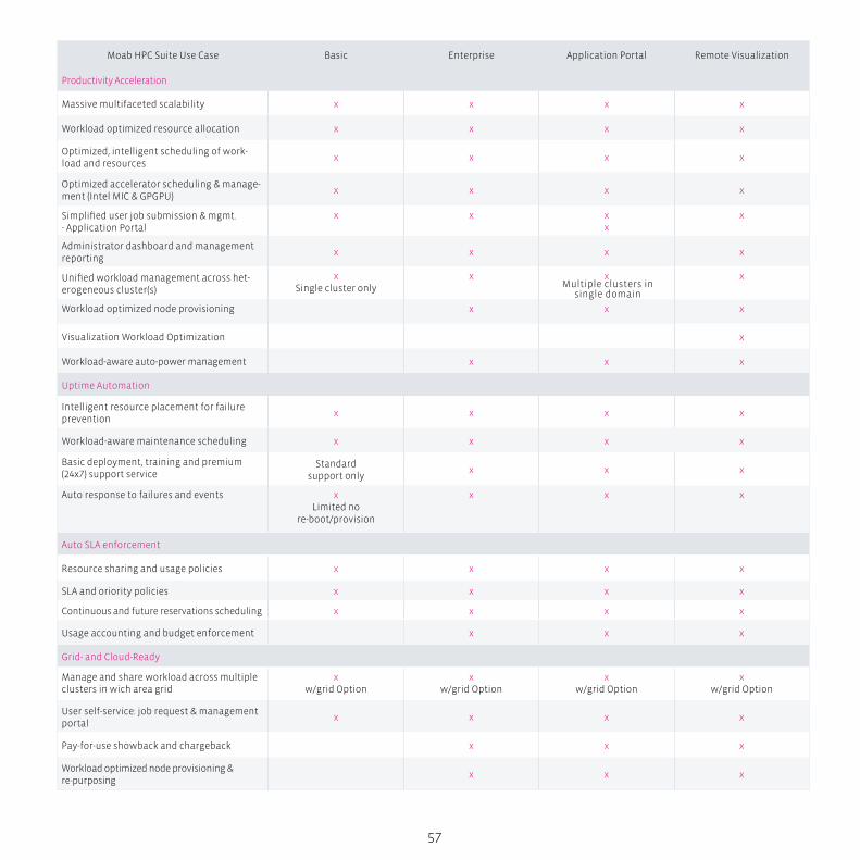
57
Moab HPC Suite Use Case Basic Enterprise Application Portal Remote Visualization
Productivity Acceleration
Massive multifaceted scalability x x x x
Workload optimized resource allocation x x x x
Optimized, intelligent scheduling of work-load and resources
x x x x
Optimized accelerator scheduling & manage-ment (Intel MIC & GPGPU)
x x x x
Simplified user job submission & mgmt.- Application Portal
x x xx
x
Administrator dashboard and management reporting
x x x x
Unified workload management across het-erogeneous cluster(s)
xSingle cluster only
x x x
Workload optimized node provisioning x x x
Visualization Workload Optimization x
Workload-aware auto-power management x x x
Uptime Automation
Intelligent resource placement for failure prevention
x x x x
Workload-aware maintenance scheduling x x x x
Basic deployment, training and premium (24x7) support service
Standard support only
x x x
Auto response to failures and events xLimited no
re-boot/provision
x x x
Auto SLA enforcement
Resource sharing and usage policies x x x x
SLA and oriority policies x x x x
Continuous and future reservations scheduling x x x x
Usage accounting and budget enforcement x x x
Grid- and Cloud-Ready
Manage and share workload across multiple clusters in wich area grid
xw/grid Option
xw/grid Option
xw/grid Option
xw/grid Option
User self-service: job request & management portal
x x x x
Pay-for-use showback and chargeback x x x
Workload optimized node provisioning & re-purposing
x x x
Multiple clusters in single domain
58
Intelligent HPC Workload Management
Moab HPC Suite –
Application Portal Edition
Moab HPC Suite – Application Portal EditionMoab HPC Suite – Application Portal Edition provides easy sin-
gle-point access to common technical applications, data, resourc-
es, and job submissions to accelerate project completion and colla-
boration for end users while reducing computing costs. It enables
more of your internal staff and partners to collaborate from any-
where using HPC applications and resources without any special-
ized HPC training while your intellectual property stays secure.
The optimization policies Moab provides significantly reduces
the costs and complexity of keeping up with compute demand
by optimizing resource sharing, utilization and higher through-
put while still balancing different service levels and priorities.
Remove the Barriers to Harnessing HPCOrganizations of all sizes and types are looking to harness the
potential of high performance computing (HPC) to enable and
accelerate more competitive product design and research. To do
this, you must find a way to extend the power of HPC resources to
designers, researchers and engineers not familiar with or trained
on using the specialized HPC technologies. Simplifying the user
access to and interaction with applications running on more
efficient HPC clusters removes the barriers to discovery and in-
novation for all types of departments and organizations. Moab
HPC Suite – Application Portal Edition provides easy single-point
access to common technical applications, data, HPC resources,
and job submissions to accelerate research analysis and collab-
oration process for end users while reducing computing costs.
HPC Ease of Use Drives Productivity Moab HPC Suite – Application Portal Edition improves ease of
use and productivity for end users using HPC resources with sin-
gle-point access to their common technical applications, data,
resources, and job submissions across the design and research
process. It simplifies the specification and running of jobs on HPC
resources to a few simple clicks on an application specific tem-
plate with key capabilities including:
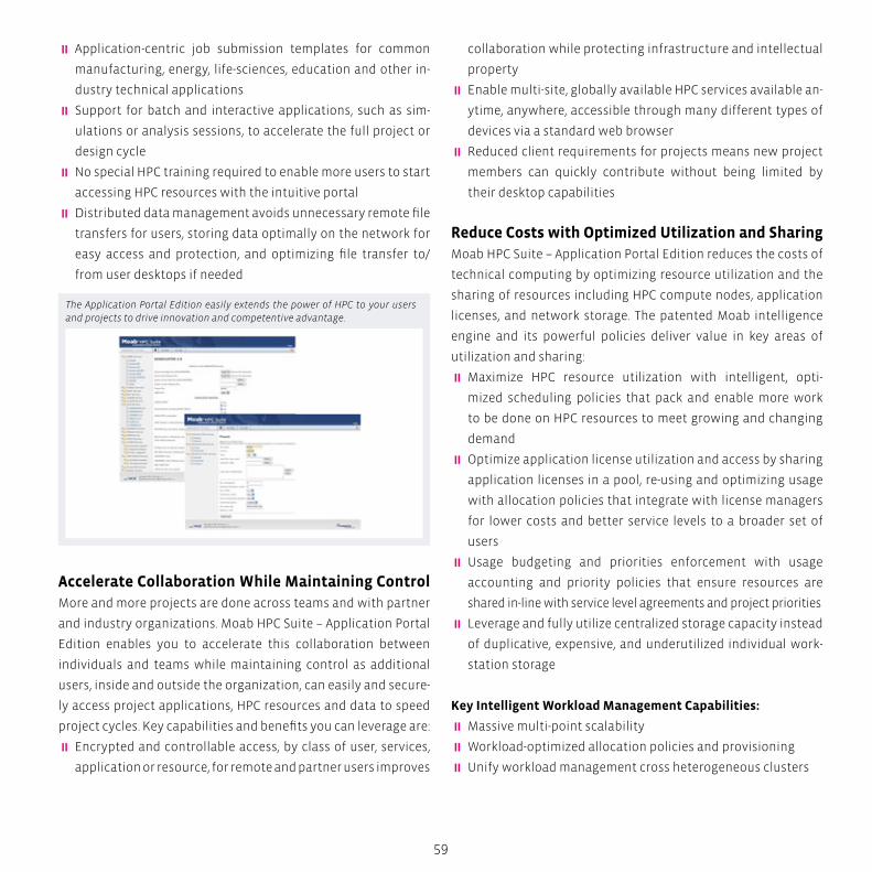
59
� Application-centric job submission templates for common
manufacturing, energy, life-sciences, education and other in-
dustry technical applications
� Support for batch and interactive applications, such as sim-
ulations or analysis sessions, to accelerate the full project or
design cycle
� No special HPC training required to enable more users to start
accessing HPC resources with the intuitive portal
� Distributed data management avoids unnecessary remote file
transfers for users, storing data optimally on the network for
easy access and protection, and optimizing file transfer to/
from user desktops if needed
Accelerate Collaboration While Maintaining Control More and more projects are done across teams and with partner
and industry organizations. Moab HPC Suite – Application Portal
Edition enables you to accelerate this collaboration between
individuals and teams while maintaining control as additional
users, inside and outside the organization, can easily and secure-
ly access project applications, HPC resources and data to speed
project cycles. Key capabilities and benefits you can leverage are:
� Encrypted and controllable access, by class of user, services,
application or resource, for remote and partner users improves
collaboration while protecting infrastructure and intellectual
property
� Enable multi-site, globally available HPC services available an-
ytime, anywhere, accessible through many different types of
devices via a standard web browser
� Reduced client requirements for projects means new project
members can quickly contribute without being limited by
their desktop capabilities
Reduce Costs with Optimized Utilization and Sharing Moab HPC Suite – Application Portal Edition reduces the costs of
technical computing by optimizing resource utilization and the
sharing of resources including HPC compute nodes, application
licenses, and network storage. The patented Moab intelligence
engine and its powerful policies deliver value in key areas of
utilization and sharing:
� Maximize HPC resource utilization with intelligent, opti-
mized scheduling policies that pack and enable more work
to be done on HPC resources to meet growing and changing
demand
� Optimize application license utilization and access by sharing
application licenses in a pool, re-using and optimizing usage
with allocation policies that integrate with license managers
for lower costs and better service levels to a broader set of
users
� Usage budgeting and priorities enforcement with usage
accounting and priority policies that ensure resources are
shared in-line with service level agreements and project priorities
� Leverage and fully utilize centralized storage capacity instead
of duplicative, expensive, and underutilized individual work-
station storage
Key Intelligent Workload Management Capabilities:
� Massive multi-point scalability
�Workload-optimized allocation policies and provisioning
� Unify workload management cross heterogeneous clusters
The Application Portal Edition easily extends the power of HPC to your users and projects to drive innovation and competentive advantage.
60
Intelligent HPC Workload Management
Moab HPC Suite –
Remote Visualization Edition
� Optimized, intelligent scheduling
� Optimized scheduling and management of accelerators (both
Intel MIC and GPGPUs)
� Administrator dashboards and reporting tools
�Workload-aware auto power management
� Intelligent resource placement to prevent job failures
� Auto-response to failures and events
�Workload-aware future maintenance scheduling
� Usage accounting and budget enforcement
� SLA and priority polices
� Continuous plus future scheduling
Drive Your Innovation and Competitive AdvantageLeverage Adaptive Computing’s HPC expertise and award win-
ning Moab product to access or expand the opportunities HPC
can deliver your organization. Your engineers, designers, and sci-
entists will no longer have to be HPC experts to use the power
of HPC to take their projects to whole new levels of speed, inno-
vation, and competitive advantage. Moab HPC Suite- Application
Portal Edition gives you the benefits of enhanced user produc-
tivity and tools with optimized workload management for HPC
system efficiency to reduce costs as well.
Managing the World’s Top Systems, Ready to Manage YoursMoab manages the largest, most scale-intensive and complex
high performance computing environments in the world. This in-
cludes many of the Top500, leading commercial, and innovative
research HPC systems. Adaptive Computing is the largest suppli-
er of HPC workload management software. Adaptive’s Moab HPC
Suite and TORQUE rank #1 and #2 as the most used scheduling/
workload management software at HPC sites and Adaptive is the
#1 vendor used across unique HPC sites.
Moab HPC Suite – Remote Visualization EditionMoab HPC Suite – Remote Visualization Edition significantly
61
reduces the costs of visualization technical computing while
improving the productivity, collaboration and security of the de-
sign and research process. It enables you to create easy, central-
ized access to shared visualization resources in a technical com-
pute cloud to reduce the hardware, network and management
costs of visualization technical computing instead of expensive
and underutilized individual workstations.
The solution centralizes applications, data and compute togeth-
er with users only transferring pixels instead of data to do their
remote simulations and analysis. This enables a wider range of
users to collaborate and be more productive at any time, on the
same data, from anywhere without any data transfer time lags
or security issues. Moab’s optimized workload management
policies maximize resource utilization and guarantee shared re-
source access to users. With Moab HPC Suite – Remote Visuali-
zation Edition you can turn your user’s data and ideas into new
products and competitive advantage cheaper and faster than
ever before.
Removing Inefficiencies in Current 3D Visualization MethodsUsing 3D and 2D visualization, valuable data is interpreted and
new innovations are discovered. There are numerous inefficien-
cies in how current technical computing methods support users
and organizations in achieving these discoveries in a cost effec-
tive way. High-cost workstations and their software are often
not fully utilized by the limited user(s) that have access to them.
They are also costly to manage and they don’t keep pace long
with workload technology requirements. In addition, the work-
station model also requires slow transfers of the large data sets
between them. This is costly and inefficient in network band-
width, user productivity, and team collaboration while posing
increased data and security risks. There is a solution that re-
moves these inefficiencies using new technical cloud computing
models. Moab HPC Suite – Remote Visualization Edition signifi-
cantly reduces the costs of visualization technical computing
while improving the productivity, collaboration and security of
the design and research process.
Reduce the Costs of Visualization Technical ComputingMoab HPC Suite – Remote Visualization Edition significantly re-
duces the hardware, network and management costs of visual-
ization technical computing. It enables you to create easy, cen-
tralized access to shared visualization compute, application and
data resources. These compute, application, and data resources
reside in a technical compute cloud in your data center instead
of in expensive and underutilized individual workstations.
� Reduce hardware costs by consolidating expensive individual
technical workstations into centralized visualization servers
for higher utilization by multiple users; reduce additive or up-
grade technical workstation or specialty hardware purchases,
such as GPUs, for individual users.
� Reduce management costs by moving from remote user work-
stations that are difficult and expensive to maintain, upgrade,
and back-up to centrally managed visualization servers that
require less admin overhead
� Decrease network access costs and congestion as significant-
ly lower loads of just compressed, visualized pixels are mov-
ing to users, not full data sets
� Reduce energy usageas centralized visualization servers
consume less energy for the user demand met
� Reduce data storage costs by consolidating data into common
storage node(s) instead of under-utilized individual storage
Improve Collaboration, Productivity and SecurityWith Moab HPC Suite – Remote Visualization Edition, you can im-
prove the productivity, collaboration and security of the design
and research process by only transferring pixels instead of data
to users to do their simulations and analysis. This enables a wider
range of users to collaborate and be more productive at any time,
62
on the same data, from anywhere without any data transfer time
lags or security issues. Users also have improved immediate ac-
cess to specialty applications and resources – like GPUs – they
might need for a project so they are no longer limited by person-
al workstation constraints or to a single working location.
� Improve workforce collaboration by enabling multiple users
to access and collaborate on the same interactive application
data at the same time from almost any location or device,
with little or no training needed
� Eliminate data transfer time lags for users by keeping data
close to the visualization applications and compute resources
instead of transferring back and forth to remote workstations;
only smaller compressed pixels are transferred
� Improve security with centralized data storage so data no
longer gets transferred to where it shouldn’t, gets lost, or gets
inappropriately accessed on remote workstations, only pixels
get moved
Maximize Utilization and Shared Resource GuaranteesMoab HPC Suite – Remote Visualization Edition maximizes your
resource utilization and scalability while guaranteeing shared
resource access to users and groups with optimized workload
management policies. Moab’s patented policy intelligence en-
gine optimizes the scheduling of the visualization sessions
across the shared resources to maximize standard and specialty
resource utilization, helping them scale to support larger vol-
umes of visualization workloads. These intelligent policies also
guarantee shared resource access to users to ensure a high ser-
vice level as they transition from individual workstations.
� Guarantee shared visualization resource access for users
with priority policies and usage budgets that ensure they
receive the appropriate service level. Policies include ses-
sion priorities and reservations, number of users per node,
fairshare usage policies, and usage accounting and budgets
across multiple groups or users.
Intelligent HPC Workload Management
Moab HPC Suite –
Remote Visualization Edition
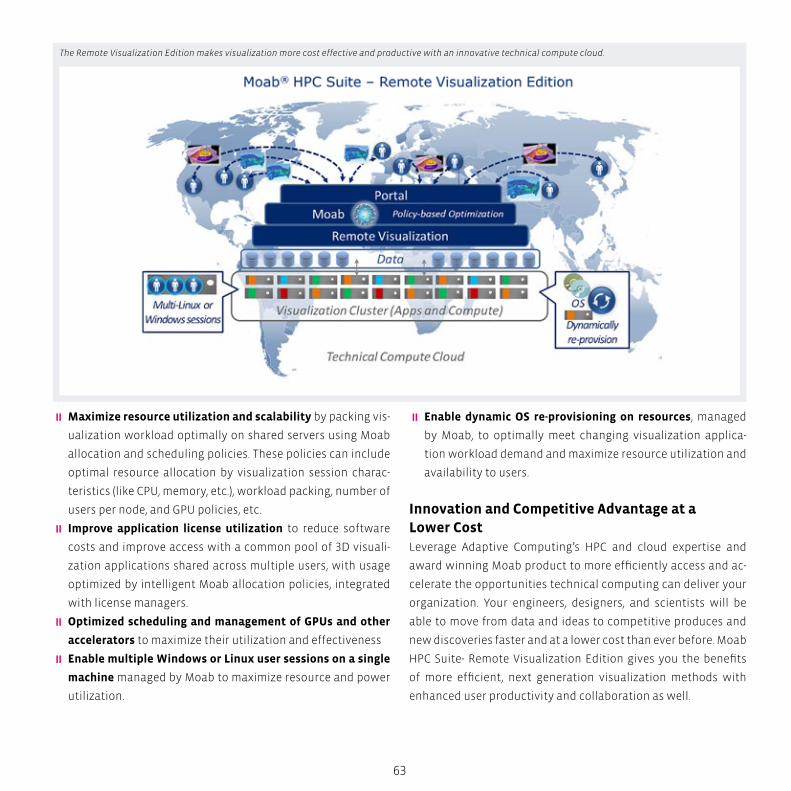
63
�Maximize resource utilization and scalability by packing vis-
ualization workload optimally on shared servers using Moab
allocation and scheduling policies. These policies can include
optimal resource allocation by visualization session charac-
teristics (like CPU, memory, etc.), workload packing, number of
users per node, and GPU policies, etc.
� Improve application license utilization to reduce software
costs and improve access with a common pool of 3D visuali-
zation applications shared across multiple users, with usage
optimized by intelligent Moab allocation policies, integrated
with license managers.
� Optimized scheduling and management of GPUs and other
accelerators to maximize their utilization and effectiveness
� Enable multiple Windows or Linux user sessions on a single
machine managed by Moab to maximize resource and power
utilization.
� Enable dynamic OS re-provisioning on resources, managed
by Moab, to optimally meet changing visualization applica-
tion workload demand and maximize resource utilization and
availability to users.
Innovation and Competitive Advantage at a Lower CostLeverage Adaptive Computing’s HPC and cloud expertise and
award winning Moab product to more efficiently access and ac-
celerate the opportunities technical computing can deliver your
organization. Your engineers, designers, and scientists will be
able to move from data and ideas to competitive produces and
new discoveries faster and at a lower cost than ever before. Moab
HPC Suite- Remote Visualization Edition gives you the benefits
of more efficient, next generation visualization methods with
enhanced user productivity and collaboration as well.
The Remote Visualization Edition makes visualization more cost effective and productive with an innovative technical compute cloud.

64
Optimizing Accelerators with Moab HPC SuiteHarnessing the Power of Intel Xeon Phi and GPGPUs
The mathematical acceleration delivered by many-core General
Purpose Graphics Processing Units (GPGPUs) offers significant
performance advantages for many classes of numerically inten-
sive applications. Parallel computing tools such as NVIDIA’s CUDA
and the openCL framework have made harnessing the power of
these technologies much more accessible to developers, result-
ing in the increasing deployment of hybrid GPGPU-based sys-
tems and introducing significant challenges for administrators
and workload management systems.
The new Intel Xeon Phi coprocessors offer breakthrough perfor-
mance for highly parallel applications with the benefit of leverag-
ing existing code and flexibility in programming models for fast-
er application development. Moving an application to Intel Xeon
Phi coprocessors has the promising benefit of requiring substan-
tially less effort and lower power usage. Such a small investment
can reap big performance gains for both data-intensive and
numerical or scientific computing applications that can make
the most of the Intel Many Integrated Cores (MIC) technology.
So it is no surprise that organizations are quickly embracing
these new coprocessors in their HPC systems. The main goal is to
create breakthrough discoveries, products and research that im-
prove our world. Harnessing and optimizing the power of these
new accelerator technologies is key to doing this as quickly as
possible. Moab HPC Suite helps organizations easily integrate ac-
celerator and coprocessor technologies into their HPC systems,
optimizing their utilization for the right work-loads and prob-
lems they are trying to solve.
Moab HPC Suite automatically schedules hybrid systems incor-
porating Intel Xeon Phi coprocessors and GPGPU accelerators,
optimizing their utilization as just another resource type with
Intelligent HPC Workload Management
Optimizing Accelerators with
Moab HPC Suite
65
policies. Organizations can choose the accelerators that best
meet their different workload needs.
Managing Hybrid Accelerator SystemsHybrid accelerator systems add a new dimension of manage-
ment complexity when allocating workloads to available re-
sources. In addition to the traditional needs of aligning workload
placement with software stack dependencies, CPU type, memo-
ry, and interconnect requirements, intelligent workload manage-
ment systems now need to consider:
Workload’s ability to exploit Xeon Phi or GPGPU technology
Additional software dependencies and reduce costs, including
topology-based allocation.
Current health and usage status of available Xeon Phis or GPG-
PUs Resource configuration for type and number of Xeon Phis or
GPGPUs Moab HPC Suite auto detects which types of accelera-
tors are where in the system to reduce the management effort
and costs as these processors are introduced and maintained to-
gether in an HPC system. This gives customers maximum choice
and performance in selecting the accelerators that work best for
each of their workloads, whether Xeon Phi, GPGPU or a hybrid
mix of the two.
Optimizing Intel Xeon Phi and GPGPUs Utilization System and application diversity is one of the first issues work-
load management software must address in optimizing acceler-
ator utilization. The ability of current codes to use GPGPUs and
Xeon Phis effectively, ongoing cluster expansion, and costs usu-
ally mean only a portion of a system will be equipped with one
or a mix of both types of accelerators. Moab HPC Suite has a two-
fold role in reducing the complexity of their administration and
optimizing their utilization. First, it must be able to automatical-
ly detect new GPGPUs or Intel Xeon Phi coprocessors in the envi-
ronment and their availability without the cumbersome burden
of manual administrator configuration. Second, and most impor-
tantly, it must accurately match Xeon Phi-bound or GPGPU-en-
abled workloads with the appropriately equipped resources in
addition to managing contention for those limited resources
according to organizational policy. Moab’s powerful allocation
and prioritization policies can ensure the right jobs from users
and groups get to the optimal accelerator resources at the right
time. This keeps the accelerators at peak utilization for the right
priority jobs.
Moab’s policies are a powerful ally to administrators in auto de-
termining the optimal Xeon Phi coprocessor or GPGPU to use
and ones to avoid when scheduling jobs. These allocation poli-
cies can be based on any of the GPGPU or Xeon Phi metrics such
as memory (to ensure job needs are met), temperature (to avoid
hardware errors or failures), utilization, or other metrics. Use the
following metrics in policies to optimize allocation of Intel Xeon
Phi coprocessors:
� Number of Cores
� Number of Hardware Threads
� Physical Memory
� Free Physical Memory
� Swap Memory
� Free Swap Memory
� Max Frequency (in MHz)
Use the following metrics in policies to optimize allocation of
GPGPUs and for management diagnostics:
� Error counts; single/double-bit, commands to reset counts
� Temperature
� Fan speed
� Memory; total, used, utilization
� Utilization percent
� Metrics time stamp
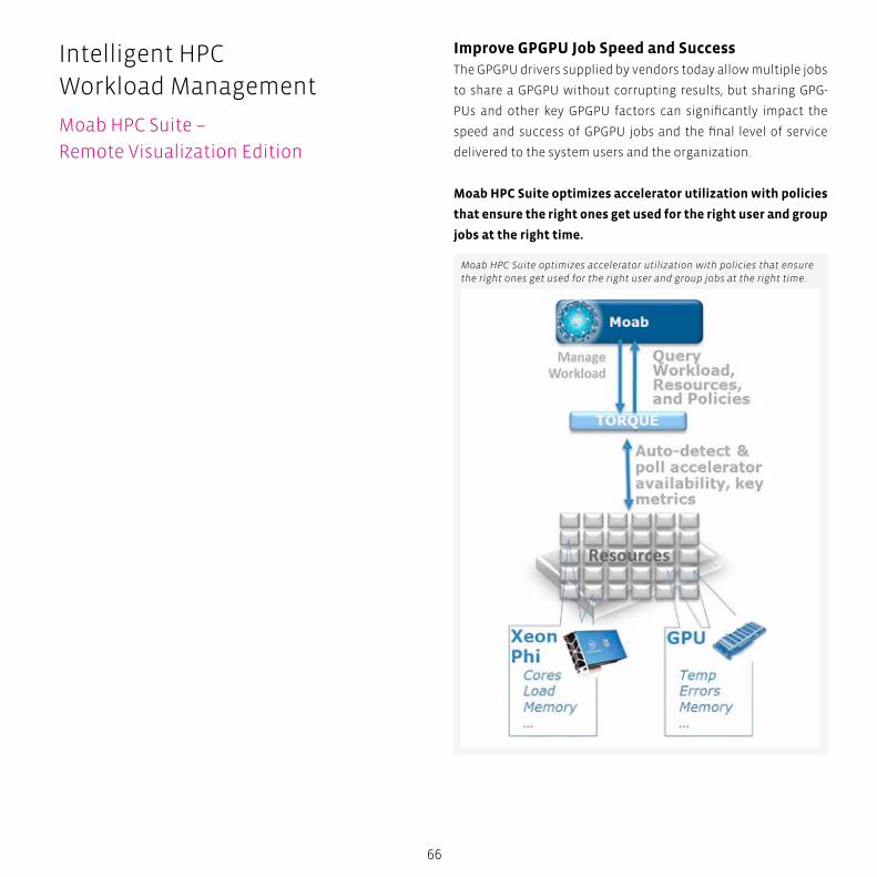
66
Improve GPGPU Job Speed and SuccessThe GPGPU drivers supplied by vendors today allow multiple jobs
to share a GPGPU without corrupting results, but sharing GPG-
PUs and other key GPGPU factors can significantly impact the
speed and success of GPGPU jobs and the final level of service
delivered to the system users and the organization.
Moab HPC Suite optimizes accelerator utilization with policies
that ensure the right ones get used for the right user and group
jobs at the right time.
Moab HPC Suite optimizes accelerator utilization with policies that ensure the right ones get used for the right user and group jobs at the right time.
Intelligent HPC Workload Management
Moab HPC Suite –
Remote Visualization Edition
67
Consider the example of a user estimating the time for a GPGPU
job based on exclusive access to a GPGPU, but the workload man-
ager allowing the GPGPU to be shared when the job is scheduled.
The job will likely exceed the estimated time and be terminated
by the workload manager unsuccessfully, leaving a very unsatis-
fied user and the organization, group or project they represent.
Moab HPC Suite provides the ability to schedule GPGPU jobs to
run exclusively and finish in the shortest time possible for certain
types, or classes of jobs or users to ensure job speed and success.
Optimize Performance and InnovationAdaptive Computing’s HPC expertise and award winning Moab
product help you optimize the utilization and performance from
your accelerators so you get from calculations to innovation
faster:
Simplify management:
auto detection of GPGPUs or Intel Xeon Phi coprocessors
Maximize utilization:
policies favor GPGPU or Xeon Phi-oriented jobs over other jobs
for accelerator-equipped resources
Maximize job success:
policies allocate the optimal accelerator, in the optimal mode,
at given time
Maximize service level:
policies designate priority scheduling for users, groups, classes
using limited accelerator resources

Remote Visualization and Workflow OptimizationIt’s human nature to want to ‘see’ the results from simulations, tests, and analy-
ses. Up until recently, this has meant ‘fat’ workstations on many user desktops. This
approach provides CPU power when the user wants it – but as dataset size increases,
there can be delays in downloading the results.
Also, sharing the results with colleagues means gathering around the workstation – not
always possible in this globalized, collaborative workplace.
Life
Sci
en
ces
CA
E
Hig
h P
erf
orm
an
ce C
om
pu
tin
g
Big
Da
ta A
na
lyti
cs
Sim
ula
tio
n
CA
D
70
Aerospace, Automotive and ManufacturingThe complex factors involved in CAE range from compute-in-
tensive data analysis to worldwide collaboration between de-
signers, engineers, OEM’s and suppliers. To accommodate these
factors, Cloud (both internal and external) and Grid Computing
solutions are increasingly seen as a logical step to optimize IT
infrastructure usage for CAE. It is no surprise then, that automo-
tive and aerospace manufacturers were the early adopters of
internal Cloud and Grid portals.
Manufacturers can now develop more “virtual products” and
simulate all types of designs, fluid flows, and crash simulations.
Such virtualized products and more streamlined collaboration
environments are revolutionizing the manufacturing process.
With NICE EnginFrame in their CAE environment engineers can
take the process even further by connecting design and simula-
tion groups in “collaborative environments” to get even greater
benefits from “virtual products”. Thanks to EnginFrame, CAE en-
gineers can have a simple intuitive collaborative environment
that can care of issues related to:
� Access & Security - Where an organization must give access
to external and internal entities such as designers, engi-
neers and suppliers.
� Distributed collaboration - Simple and secure connection of
design and simulation groups distributed worldwide.
� Time spent on IT tasks – By eliminating time and resources spent
using cryptic job submission commands or acquiring knowl-
edge of underlying compute infrastructures, engineers can
spend more time concentrating on their core design tasks.
EnginFrame’s web based interface can be used to access the
compute resources required for CAE processes. This means ac-
cess to job submission & monitoring tasks, input & output data
associated with industry standard CAE/CFD applications for
Fluid-Dynamics, Structural Analysis, Electro Design and Design
Remote Visualization
NICE EnginFrame:
A Technical Computing Portal
71
Collaboration (like Abaqus, Ansys, Fluent, MSC Nastran, PAM-
Crash, LS-Dyna, Radioss) without cryptic job submission com-
mands or knowledge of underlying compute infrastructures.
EnginFrame has a long history of usage in some of the most
prestigious manufacturing organizations worldwide including
Aerospace companies like AIRBUS, Alenia Space, CIRA, Galileo
Avionica, Hamilton Sunstrand, Magellan Aerospace, MTU and
Automotive companies like Audi, ARRK, Brawn GP, Bridgestone,
Bosch, Delphi, Elasis, Ferrari, FIAT, GDX Automotive, Jaguar-Lan-
dRover, Lear, Magneti Marelli, McLaren, P+Z, RedBull, Swagelok,
Suzuki, Toyota, TRW.
Life Sciences and HealthcareNICE solutions are deployed in the Life Sciences sector at compa-
nies like BioLab, Partners HealthCare, Pharsight and the M.D.An-
derson Cancer Center; also in leading research projects like DEISA
or LitBio in order to allow easy and transparent use of computing
resources without any insight of the HPC infrastructure.
The Life Science and Healthcare sectors have some very strict
requirement when choosing its IT solution like EnginFrame, for
instance:
� Security - To meet the strict security & privacy requirements
of the biomedical and pharmaceutical industry any solution
needs to take account of multiple layers of security and au-
thentication.
� Industry specific software - ranging from the simplest custom
tool to the more general purpose free and open middlewares.
EnginFrame’s modular architecture allows for different Grid
middlewares and software including leading Life Science appli-
cations like Schroedinger Glide, EPFL RAxML, BLAST family, Tav-
erna, and R) to be exploited, R Users can compose elementary
services into complex applications and “virtual experiments”,
run, monitor, and build workflows via a standard Web browser.
EnginFrame also has highly tunable resource sharing and fine-
grained access control where multiple authentication systems
(like Active Directory, Kerberos/LDAP) can be exploited simulta-
neously.
Growing complexity in globalized teamsHPC systems and Enterprise Grids deliver unprecedented time-
to-market and performance advantages to many research and
corporate customers, struggling every day with compute and
data intensive processes.
This often generates or transforms massive amounts of jobs and
data, that needs to be handled and archived efficiently to deliv-
er timely information to users distributed in multiple locations,
with different security concerns.
Poor usability of such complex systems often negatively im-
pacts users’ productivity, and ad-hoc data management often
increases information entropy and dissipates knowledge and
intellectual property.
The solutionSolving distributed computing issues for our customers, we
understand that a modern, user-friendly web front-end to HPC
and Grids can drastically improve engineering productivity, if
properly designed to address the specific challenges of the Tech-
nical Computing market
NICE EnginFrame overcomes many common issues in the areas
of usability, data management, security and integration, open-
ing the way to a broader, more effective use of the Technical
Computing resources.
The key components of the solution are:
� A flexible and modular Java-based kernel, with clear separa-
tion between customizations and core services
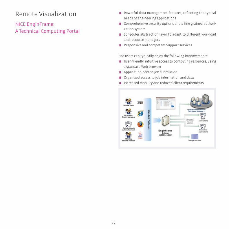
72
� Powerful data management features, reflecting the typical
needs of engineering applications
� Comprehensive security options and a fine grained authori-
zation system
� Scheduler abstraction layer to adapt to different workload
and resource managers
� Responsive and competent Support services
End users can typically enjoy the following improvements:
� User-friendly, intuitive access to computing resources, using
a standard Web browser
� Application-centric job submission
� Organized access to job information and data
� Increased mobility and reduced client requirements
Remote Visualization
NICE EnginFrame:
A Technical Computing Portal
73
On the other side, the Technical Computing Portal delivers signif-
icant added-value for system administrators and IT:
� Reduced training needs to enable users to access the
resources
� Centralized configuration and immediate deployment of
services
� Comprehensive authorization to access services and
information
� Reduced support calls and submission errors
Coupled with our Remote Visualization solutions, our custom-
ers quickly deploy end-to-end engineering processes on their
Intranet, Extranet or Internet.
74
Remote Visualization
Desktop Cloud Visualization
Solving distributed computing issues for our customers, it is
easy to understand that a modern, user-friendly web front-end
to HPC and grids can drastically improve engineering productiv-
ity, if properly designed to address the specific challenges of the
Technical Computing market.
Remote VisualizationIncreasing dataset complexity (millions of polygons, interacting
components, MRI/PET overlays) means that as time comes to
upgrade and replace the workstations, the next generation of
hardware needs more memory, more graphics processing, more
disk, and more CPU cores. This makes the workstation expen-
sive, in need of cooling, and noisy.
Innovation in the field of remote 3D processing now allows com-
panies to address these issues moving applications away from
the Desktop into the data center. Instead of pushing data to the
application, the application can be moved near the data.
Instead of mass workstation upgrades, remote visualization
allows incremental provisioning, on-demand allocation, better
management and efficient distribution of interactive sessions
and licenses. Racked workstations or blades typically have low-
er maintenance, cooling, replacement costs, and they can ex-
tend workstation (or laptop) life as “thin clients”.
The solution
Leveraging their expertise in distributed computing and web-
based application portals, NICE offers an integrated solution to
access, load balance and manage applications and desktop ses-
sions running within a visualization farm. The farm can include
both Linux and Windows resources, running on heterogeneous
hardware.
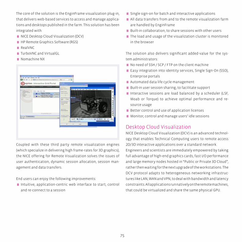
75
The core of the solution is the EnginFrame visualization plug-in,
that delivers web-based services to access and manage applica-
tions and desktops published in the farm. This solution has been
integrated with:
� NICE Desktop Cloud Visualization (DCV)
� HP Remote Graphics Software (RGS)
� RealVNC
� TurboVNC and VirtualGL
� Nomachine NX
Coupled with these third party remote visualization engines
(which specialize in delivering high frame-rates for 3D graphics),
the NICE offering for Remote Visualization solves the issues of
user authentication, dynamic session allocation, session man-
agement and data transfers.
End users can enjoy the following improvements:
� Intuitive, application-centric web interface to start, control
and re-connect to a session
� Single sign-on for batch and interactive applications
� All data transfers from and to the remote visualization farm
are handled by EnginFrame
� Built-in collaboration, to share sessions with other users
� The load and usage of the visualization cluster is monitored
in the browser
The solution also delivers significant added-value for the sys-
tem administrators:
� No need of SSH / SCP / FTP on the client machine
� Easy integration into identity services, Single Sign-On (SSO),
Enterprise portals
� Automated data life cycle management
� Built-in user session sharing, to facilitate support
� Interactive sessions are load balanced by a scheduler (LSF,
Moab or Torque) to achieve optimal performance and re-
source usage
� Better control and use of application licenses
� Monitor, control and manage users’ idle sessions
Desktop Cloud VisualizationNICE Desktop Cloud Visualization (DCV) is an advanced technol-
ogy that enables Technical Computing users to remote access
2D/3D interactive applications over a standard network.
Engineers and scientists are immediately empowered by taking
full advantage of high-end graphics cards, fast I/O performance
and large memory nodes hosted in “Public or Private 3D Cloud”,
rather then waiting for the next upgrade of the workstations. The
DCV protocol adapts to heterogeneous networking infrastruc-
tures like LAN, WAN and VPN, to deal with bandwidth and latency
constraints. All applications run natively on the remote machines,
that could be virtualized and share the same physical GPU.
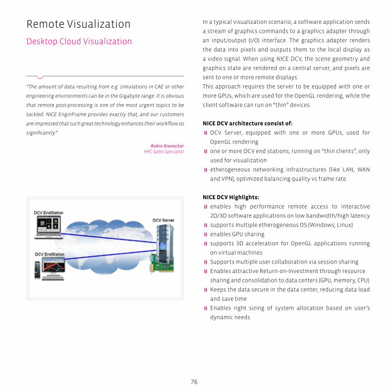
76
In a typical visualization scenario, a software application sends
a stream of graphics commands to a graphics adapter through
an input/output (I/O) interface. The graphics adapter renders
the data into pixels and outputs them to the local display as
a video signal. When using NICE DCV, the scene geometry and
graphics state are rendered on a central server, and pixels are
sent to one or more remote displays.
This approach requires the server to be equipped with one or
more GPUs, which are used for the OpenGL rendering, while the
client software can run on “thin” devices.
NICE DCV architecture consist of:
� DCV Server, equipped with one or more GPUs, used for
OpenGL rendering
� one or more DCV end stations, running on “thin clients”, only
used for visualization
� etherogeneous networking infrastructures (like LAN, WAN
and VPN), optimized balancing quality vs frame rate
NICE DCV Highlights:
� enables high performance remote access to interactive
2D/3D software applications on low bandwidth/high latency
� supports multiple etherogeneous OS (Windows, Linux)
� enables GPU sharing
� supports 3D acceleration for OpenGL applications running
on virtual machines
� Supports multiple user collaboration via session sharing
� Enables attractive Return-on-Investment through resource
sharing and consolidation to data centers (GPU, memory, CPU)
� Keeps the data secure in the data center, reducing data load
and save time
� Enables right sizing of system allocation based on user’s
dynamic needs
Remote Visualization
Desktop Cloud Visualization
“The amount of data resulting from e.g. simulations in CAE or other
engineering environments can be in the Gigabyte range. It is obvious
that remote post-processing is one of the most urgent topics to be
tackled. NICE EnginFrame provides exactly that, and our customers
are impressed that such great technology enhances their workflow so
significantly.”
Robin KieneckerHPC Sales Specialist
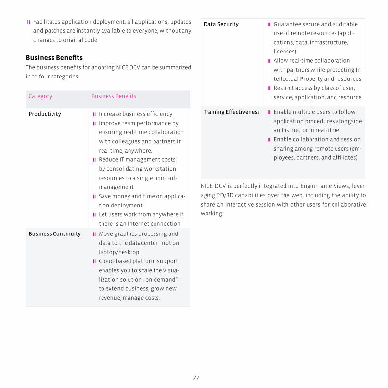
77
� Facilitates application deployment: all applications, updates
and patches are instantly available to everyone, without any
changes to original code
Business BenefitsThe business benefits for adopting NICE DCV can be summarized
in to four categories:
Category Business Benefits
Productivity � Increase business efficiency
� Improve team performance by
ensuring real-time collaboration
with colleagues and partners in
real time, anywhere.
� Reduce IT management costs
by consolidating workstation
resources to a single point-of-
management
� Save money and time on applica-
tion deployment
� Let users work from anywhere if
there is an Internet connection
Business Continuity � Move graphics processing and
data to the datacenter - not on
laptop/desktop
� Cloud-based platform support
enables you to scale the visua-
lization solution „on-demand“
to extend business, grow new
revenue, manage costs.
Data Security � Guarantee secure and auditable
use of remote resources (appli-
cations, data, infrastructure,
licenses)
� Allow real-time collaboration
with partners while protecting In-
tellectual Property and resources
� Restrict access by class of user,
service, application, and resource
Training Effectiveness � Enable multiple users to follow
application procedures alongside
an instructor in real-time
� Enable collaboration and session
sharing among remote users (em-
ployees, partners, and affiliates)
NICE DCV is perfectly integrated into EnginFrame Views, lever-
aging 2D/3D capabilities over the web, including the ability to
share an interactive session with other users for collaborative
working.
BOX
78
Cloud Computing With transtec and NICECloud Computing is a style of computing in which dynamically
scalable and often virtualized resources are provided as a service
over the Internet. Users need not have knowledge of, expertise in,
or control over the technology infrastructure in the “cloud” that
supports them. The concept incorporates technologies that have
the common theme of reliance on the Internet for satisfying the
computing needs of the users. Cloud Computing services usually
provide applications online that are accessed from a web brows-
er, while the software and data are stored on the servers.
Companies or individuals engaging in Cloud Computing do not
own the physical infrastructure hosting the software platform
in question. Instead, they avoid capital expenditure by renting
usage from a third-party provider (except for the case of ‘Private
Cloud’ - see below). They consume resources as a service, paying
instead for only the resources they use. Many Cloud Comput-
ing offerings have adopted the utility computing model, which
is analogous to how traditional utilities like electricity are con-
sumed, while others are billed on a subscription basis.
The main advantage offered by Cloud solutions is the reduction
of infrastructure costs, and of the infrastructure’s maintenance.
By not owning the hardware and software, Cloud users avoid
capital expenditure by renting usage from a third-party provider.
Customers pay for only the resources they use.
The advantage for the provider of the Cloud, is that sharing com-
puting power among multiple tenants improves utilization rates,
as servers are not left idle, which can reduce costs and increase
efficiency.
Remote Visualization
Cloud Computing With transtec and NICE

79
Public cloud
Public cloud or external cloud describes cloud computing in the
traditional mainstream sense, whereby resources are dynam-
ically provisioned on a fine-grained, self-service basis over the
Internet, via web applications/web services, from an off-site
third-party provider who shares resources and bills on a fine-
grained utility computing basis.
Private cloud
Private cloud and internal cloud describe offerings deploying
cloud computing on private networks. These solutions aim to
“deliver some benefits of cloud computing without the pitfalls”,
capitalizing on data security, corporate governance, and relia-
bility concerns. On the other hand, users still have to buy, deploy,
manage, and maintain them, and as such do not benefit from
lower up-front capital costs and less hands-on management.
Architecture
The majority of cloud computing infrastructure, today, consists
of reliable services delivered through data centers and built on
servers with different levels of virtualization technologies. The
services are accessible anywhere that has access to networking
infrastructure. The Cloud appears as a single point of access
for all the computing needs of consumers. The offerings need
to meet the quality of service requirements of customers and
typically offer service level agreements, and, at the same time
proceed over the typical limitations.
The architecture of the computing platform proposed by NICE
(fig. 1) differs from the others in some interesting ways:
� you can deploy it on an existing IT infrastructure, because it
is completely decoupled from the hardware infrastructure
� it has a high level of modularity and configurability, resulting
in being easily customizable for the user’s needs
� based on the NICE EnginFrame technology, it is easy to build
graphical web-based interfaces to provide several applica-
tions, as web services, without needing to code or compile
source programs
� it utilises the existing methodology in place for authentica-
tion and authorization
80
Further, because the NICE Cloud solution is built on advanced
IT technologies, including virtualization and workload manage-
ment, the execution platform is dynamically able to allocate,
monitor, and configure a new environment as needed by the
application, inside the Cloud infrastructure. The NICE platform
offers these important properties:
� Incremental Scalability: the quantity of computing and
storage resources, provisioned to the applications, changes
dynamically depending on the workload
� Reliability and Fault-Tolerance: because of the virtualiza-
tion of the hardware resources and the multiple redundant
hosts, the platform adjusts the resources needed from the
applications, without disruption during disasters or crashes
� Service Level Agreement: the use of advanced systems for
the dynamic allocation of the resources, allows the guaran-
tee of service level, agreed across applications and services;
� Accountability: the continuous monitoring of the resourc-
es used by each application (and user), allows the setup of
services that users can access in a pay-per-use mode, or sub-
scribing to a specific contract. In the case of an Enterprise
Cloud, this feature allows costs to be shared among the cost
centers of the company.
transtec has a long-term experience in Engineering environ-
ments, especially from the CAD/CAE sector. This allow us to
provide customers from this area with solutions that greatly en-
hance their workflow and minimizes time-to-result.
This, together with transtec’s offerings of all kinds of services,
allows our customers to fully focus on their productive work,
and have us do the environmental optimizations.
Remote Visualization
NVIDIA GRID Boards
81
Graphics accelerated virtual desktops and applicationsNVIDIA GRID for large corporations offers the ability to offload
graphics processing from the CPU to the GPU in virtualised envi-
ronments, allowing the data center manager to deliver true PC
graphics-rich experiences to more users for the first time.
Benefits of NVIDIA GRID for IT:
� Leverage industry-leading remote visualization solutions like
NICE DCV
� Add your most graphics-intensive users to your virtual solu-
tion
� Improve the productivity of all users
Benefits of NVIDIA GRID for users:
� Highly responsive windows and rich multimedia experiences
� Access to all critical applications, including the most 3D-intensive
� Access from anywhere, on any device
NVIDIA GRID BoardsNVIDIA’s Kepler architecture-based GRID boards are specifically
designed to enable rich graphics in virtualised environments.
GPU VirtualisationGRID boards feature NVIDIA Kepler-based GPUs that, for the first
time, allow hardware virtualisation of the GPU. This means mul-
tiple users can share a single GPU, improving user density while
providing true PC performance and compatibility.
Low-Latency Remote DisplayNVIDIA’s patented low-latency remote display technology great-
ly improves the user experience by reducing the lag that users
feel when interacting with their virtual machine.
With this technology, the virtual desktop screen is pushed
directly to the remoting protocol.
H.264 EncodingThe Kepler GPU includes a high-performance H.264 encoding
engine capable of encoding simultaneous streams with supe-
rior quality. This provides a giant leap forward in cloud server
efficiency by offloading the CPU from encoding functions and
allowing the encode function to scale with the number of GPUs
in a server.
Maximum User DensityGRID boards have an optimised multi-GPU design that helps to
maximise user density. The GRID K1 board features 4 GPUs and
16 GB of graphics memory, allowing it to support up to 100 users
on a single board.
Power EfficiencyGRID boards are designed to provide data center-class power
efficiency, including the revolutionary new streaming multi-
processor, called “SMX”. The result is an innovative, proven solu-
tion that delivers revolutionary performance-per-watt for the
enterprise data centre
24/7 ReliabilityGRID boards are designed, built, and tested by NVIDIA for 24/7
operation. Working closely with leading server vendors ensures
GRID cards perform optimally and reliably for the life of the sys-
tem.
Widest Range of Virtualisation SolutionsGRID cards enable GPU-capable virtualisation solutions like
XenServer or Linux KVM, delivering the flexibility to choose from
a wide range of proven solutions.
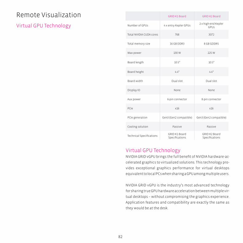
82
GRID K1 Board GRID K2 Board
Number of GPUs 4 x entry Kepler GPUs2 x high-end Kepler
GPUs
Total NVIDIA CUDA cores 768 3072
Total memory size 16 GB DDR3 8 GB GDDR5
Max power 130 W 225 W
Board length 10.5” 10.5”
Board height 4.4” 4.4”
Board width Dual slot Dual slot
Display IO None None
Aux power 6-pin connector 8-pin connector
PCIe x16 x16
PCIe generation Gen3 (Gen2 compatible) Gen3 (Gen2 compatible)
Cooling solution Passive Passive
Technical SpecificationsGRID K1 Board Specifications
GRID K2 Board Specifications
Virtual GPU TechnologyNVIDIA GRID vGPU brings the full benefit of NVIDIA hardware-ac-
celerated graphics to virtualized solutions. This technology pro-
vides exceptional graphics performance for virtual desktops
equivalent to local PCs when sharing a GPU among multiple users.
NVIDIA GRID vGPU is the industry’s most advanced technology
for sharing true GPU hardware acceleration between multiple vir-
tual desktops – without compromising the graphics experience.
Application features and compatibility are exactly the same as
they would be at the desk.
Remote Visualization
Virtual GPU Technology
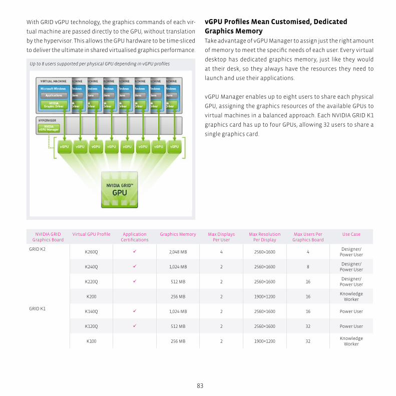
83
With GRID vGPU technology, the graphics commands of each vir-
tual machine are passed directly to the GPU, without translation
by the hypervisor. This allows the GPU hardware to be time-sliced
to deliver the ultimate in shared virtualised graphics performance.
vGPU Profiles Mean Customised, Dedicated Graphics MemoryTake advantage of vGPU Manager to assign just the right amount
of memory to meet the specific needs of each user. Every virtual
desktop has dedicated graphics memory, just like they would
at their desk, so they always have the resources they need to
launch and use their applications.
vGPU Manager enables up to eight users to share each physical
GPU, assigning the graphics resources of the available GPUs to
virtual machines in a balanced approach. Each NVIDIA GRID K1
graphics card has up to four GPUs, allowing 32 users to share a
single graphics card.
NVIDIA GRID Graphics Board
Virtual GPU Profile Application Certifications
Graphics Memory Max Displays Per User
Max Resolution Per Display
Max Users Per Graphics Board
Use Case
GRID K2K260Q 2,048 MB 4 2560×1600 4
Designer/Power User
K240Q 1,024 MB 2 2560×1600 8Designer/
Power User
K220Q 512 MB 2 2560×1600 16Designer/
Power User
K200 256 MB 2 1900×1200 16Knowledge
Worker
GRID K1K140Q 1,024 MB 2 2560×1600 16 Power User
K120Q 512 MB 2 2560×1600 32 Power User
K100 256 MB 2 1900×1200 32Knowledge
Worker
Up to 8 users supported per physical GPU depending in vGPU profiles

Intel Cluster Ready – A Quality Standard for HPC ClustersIntel Cluster Ready is designed to create predictable expectations for users and
providers of HPC clusters, primarily targeting customers in the commercial and
industrial sectors. These are not experimental “test-bed” clusters used for computer
science and computer engineering research, or high-end “capability” clusters closely
targeting their specific computing requirements that power the high-energy
physics at the national labs or other specialized research organizations.
Intel Cluster Ready seeks to advance HPC clusters used as computing resources in pro-
duction environments by providing cluster owners with a high degree of confidence
that the clusters they deploy will run the applications their scientific and engineering
staff rely upon to do their jobs. It achieves this by providing cluster hardware, software,
and system providers with a precisely defined basis for their products to meet their
customers’ production cluster requirements.
Life
Sci
en
ces
Ris
k A
na
lysi
s S
imu
lati
on
B
ig D
ata
An
aly
tics
H
igh
Pe
rfo
rma
nce
Co
mp
uti
ng
86
Intel Cluster Ready
A Quality Standard for HPC Clusters
What are the Objectives of ICR?The primary objective of Intel Cluster Ready is to make clusters
easier to specify, easier to buy, easier to deploy, and make it eas-
ier to develop applications that run on them. A key feature of ICR
is the concept of “application mobility”, which is defined as the
ability of a registered Intel Cluster Ready application – more cor-
rectly, the same binary – to run correctly on any certified Intel
Cluster Ready cluster. Clearly, application mobility is important
for users, software providers, hardware providers, and system
providers.
� Users want to know the cluster they choose will reliably run
the applications they rely on today, and will rely on tomorrow
� Application providers want to satisfy the needs of their cus-
tomers by providing applications that reliably run on their
customers’ cluster hardware and cluster stacks
� Cluster stack providers want to satisfy the needs of their cus-
tomers by providing a cluster stack that supports their cus-
tomers’ applications and cluster hardware
� Hardware providers want to satisfy the needs of their cus-
tomers by providing hardware components that supports
their customers’ applications and cluster stacks
� System providers want to satisfy the needs of their custom-
ers by providing complete cluster implementations that reli-
ably run their customers’ applications
Without application mobility, each group above must either try
to support all combinations, which they have neither the time
nor resources to do, or pick the “winning combination(s)” that
best supports their needs, and risk making the wrong choice.
The Intel Cluster Ready definition of application portability
supports all of these needs by going beyond pure portability,
(re-compiling and linking a unique binary for each platform), to
application binary mobility, (running the same binary on multi-
ple platforms), by more precisely defining the target system.
“The Intel Cluster Checker allows us to certify that our transtec HPC
clusters are compliant with an independent high quality standard.
Our customers can rest assured: their applications run as they expect.”
Marcus WiedemannHPC Solution Engineer
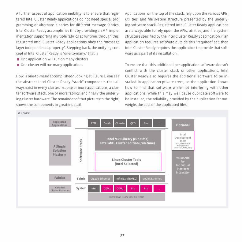
So
ftw
are
Sta
ck
Fabric
System
CFDRegisteredApplications
A SingleSolutionPlatform
Fabrics
Certified Cluster Platforms
Crash Climate QCD
Intel MPI Library (run-time)Intel MKL Cluster Edition (run-time)
Linux Cluster Tools(Intel Selected)
InfiniBand (OFED)
Intel Xeon Processor Platform
Gigabit Ethernet 10Gbit Ethernet
BioOptional
Value Addby
IndividualPlatform
Integrator
IntelDevelopment
Tools(C++, Intel Trace
Analyzer and Collector, MKL, etc.)
...
Intel OEM1 OEM2 PI1 PI2 ...
87
A further aspect of application mobility is to ensure that regis-
tered Intel Cluster Ready applications do not need special pro-
gramming or alternate binaries for different message fabrics.
Intel Cluster Ready accomplishes this by providing an MPI imple-
mentation supporting multiple fabrics at runtime; through this,
registered Intel Cluster Ready applications obey the “message
layer independence property”. Stepping back, the unifying con-
cept of Intel Cluster Ready is “one-to-many,” that is
� One application will run on many clusters
� One cluster will run many applications
How is one-to-many accomplished? Looking at Figure 1, you see
the abstract Intel Cluster Ready “stack” components that al-
ways exist in every cluster, i.e., one or more applications, a clus-
ter software stack, one or more fabrics, and finally the underly-
ing cluster hardware. The remainder of that picture (to the right)
shows the components in greater detail.
Applications, on the top of the stack, rely upon the various APIs,
utilities, and file system structure presented by the underly-
ing software stack. Registered Intel Cluster Ready applications
are always able to rely upon the APIs, utilities, and file system
structure specified by the Intel Cluster Ready Specification; if an
application requires software outside this “required” set, then
Intel Cluster Ready requires the application to provide that soft-
ware as a part of its installation.
To ensure that this additional per-application software doesn’t
conflict with the cluster stack or other applications, Intel
Cluster Ready also requires the additional software to be in-
stalled in application-private trees, so the application knows
how to find that software while not interfering with other
applications. While this may well cause duplicate software to
be installed, the reliability provided by the duplication far out-
weighs the cost of the duplicated files.
ICR Stack
88
A prime example supporting this comparison is the removal of a
common file (library, utility, or other) that is unknowingly need-
ed by some other application – such errors can be insidious to
repair even when they cause an outright application failure.
Cluster platforms, at the bottom of the stack, provide the APIs,
utilities, and file system structure relied upon by registered ap-
plications. Certified Intel Cluster Ready platforms ensure the
APIs, utilities, and file system structure are complete per the Intel
Cluster Ready Specification; certified clusters are able to provide
them by various means as they deem appropriate. Because of the
clearly defined responsibilities ensuring the presence of all soft-
ware required by registered applications, system providers have
a high confidence that the certified clusters they build are able
to run any certified applications their customers rely on. In ad-
dition to meeting the Intel Cluster Ready requirements, certified
clusters can also provide their added value, that is, other features
and capabilities that increase the value of their products.
How Does Intel Cluster Ready Accomplish its Objectives?At its heart, Intel Cluster Ready is a definition of the cluster as a
parallel application platform, as well as a tool to certify an ac-
tual cluster to the definition. Let’s look at each of these in more
detail, to understand their motivations and benefits.
A definition of the cluster as parallel application platform
The Intel Cluster Ready Specification is very much written as the
requirements for, not the implementation of, a platform upon
which parallel applications, more specifically MPI applications,
can be built and run. As such, the specification doesn’t care
whether the cluster is diskful or diskless, fully distributed or
single system image (SSI), built from “Enterprise” distributions
or community distributions, fully open source or not. Perhaps
more importantly, with one exception, the specification doesn’t
have any requirements on how the cluster is built; that one
Intel Cluster Ready
A Quality Standard for HPC Clusters
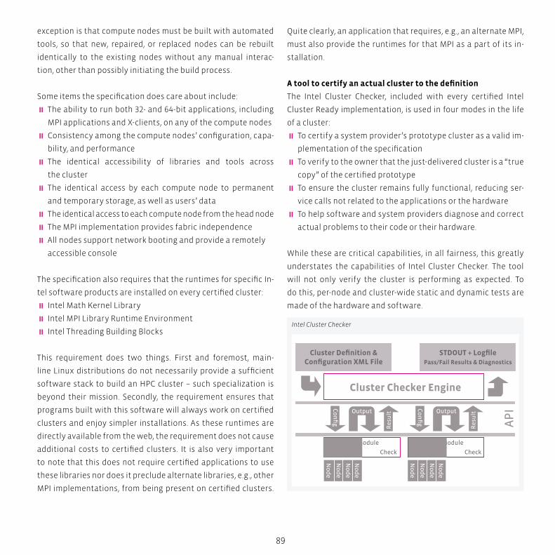
Cluster Definition & Configuration XML File
STDOUT + LogfilePass/Fail Results & Diagnostics
Cluster Checker Engine
Output
Test Module
Parallel Ops Check
Res
ult
Co
nfi
g
Output
Res
ult
AP
I
Test Module
Parallel Ops Check
Co
nfi
gN
od
e
No
de
No
de
No
de
No
de
No
de
No
de
No
de
89
exception is that compute nodes must be built with automated
tools, so that new, repaired, or replaced nodes can be rebuilt
identically to the existing nodes without any manual interac-
tion, other than possibly initiating the build process.
Some items the specification does care about include:
� The ability to run both 32- and 64-bit applications, including
MPI applications and X-clients, on any of the compute nodes
� Consistency among the compute nodes’ configuration, capa-
bility, and performance
� The identical accessibility of libraries and tools across
the cluster
� The identical access by each compute node to permanent
and temporary storage, as well as users’ data
� The identical access to each compute node from the head node
� The MPI implementation provides fabric independence
� All nodes support network booting and provide a remotely
accessible console
The specification also requires that the runtimes for specific In-
tel software products are installed on every certified cluster:
� Intel Math Kernel Library
� Intel MPI Library Runtime Environment
� Intel Threading Building Blocks
This requirement does two things. First and foremost, main-
line Linux distributions do not necessarily provide a sufficient
software stack to build an HPC cluster – such specialization is
beyond their mission. Secondly, the requirement ensures that
programs built with this software will always work on certified
clusters and enjoy simpler installations. As these runtimes are
directly available from the web, the requirement does not cause
additional costs to certified clusters. It is also very important
to note that this does not require certified applications to use
these libraries nor does it preclude alternate libraries, e.g., other
MPI implementations, from being present on certified clusters.
Quite clearly, an application that requires, e.g., an alternate MPI,
must also provide the runtimes for that MPI as a part of its in-
stallation.
A tool to certify an actual cluster to the definition
The Intel Cluster Checker, included with every certified Intel
Cluster Ready implementation, is used in four modes in the life
of a cluster:
� To certify a system provider’s prototype cluster as a valid im-
plementation of the specification
� To verify to the owner that the just-delivered cluster is a “true
copy” of the certified prototype
� To ensure the cluster remains fully functional, reducing ser-
vice calls not related to the applications or the hardware
� To help software and system providers diagnose and correct
actual problems to their code or their hardware.
While these are critical capabilities, in all fairness, this greatly
understates the capabilities of Intel Cluster Checker. The tool
will not only verify the cluster is performing as expected. To
do this, per-node and cluster-wide static and dynamic tests are
made of the hardware and software.
Intel Cluster Checker
90
The static checks ensure the systems are configured consist-
ently and appropriately. As one example, the tool will ensure
the systems are all running the same BIOS versions as well as
having identical configurations among key BIOS settings. This
type of problem – differing BIOS versions or settings – can be
the root cause of subtle problems such as differing memory con-
figurations that manifest themselves as differing memory band-
widths only to be seen at the application level as slower than ex-
pected overall performance. As is well-known, parallel program
performance can be very much governed by the performance
of the slowest components, not the fastest. In another static
check, the Intel Cluster Checker will ensure that the expected
tools, libraries, and files are present on each node, identically
located on all nodes, as well as identically implemented on all
nodes. This ensures that each node has the minimal software
stack specified by the specification, as well as identical soft-
ware stack among the compute nodes.
A typical dynamic check ensures consistent system perfor-
mance, e.g., via the STREAM benchmark. This particular test en-
sures processor and memory performance is consistent across
compute nodes, which, like the BIOS setting example above, can
be the root cause of overall slower application performance. An
additional check with STREAM can be made if the user config-
ures an expectation of benchmark performance; this check will
ensure that performance is not only consistent across the clus-
ter, but also meets expectations.
Going beyond processor performance, the Intel MPI Bench-
marks are used to ensure the network fabric(s) are performing
properly and, with a configuration that describes expected
performance levels, up to the cluster provider’s performance
expectations. Network inconsistencies due to poorly perform-
ing Ethernet NICs, InfiniBand HBAs, faulty switches, and loose or
faulty cables can be identified. Finally, the Intel Cluster Checker
is extensible, enabling additional tests to be added supporting
additional features and capabilities.
Intel Cluster Ready
Intel Cluster Ready Builds
HPC Momentum

S
N
EW
SESW
NENW
tech BOX
Cluster PlatformSoftware Tools
Reference Designs
Demand Creation
Support & Training
Specification
Co
nfi
gu
ration
Softw
are
Interco
nn
ect
Server Platfo
rm
Intel P
rocesso
r ISV Enabling
©
Intel Cluster Ready Program
91
Intel Cluster Ready Builds HPC MomentumWith the Intel Cluster Ready (ICR) program, Intel Corporation
set out to create a win-win scenario for the major constituen-
cies in the high-performance computing (HPC) cluster mar-
ket. Hardware vendors and independent software vendors
(ISVs) stand to win by being able to ensure both buyers and
users that their products will work well together straight out
of the box.
System administrators stand to win by being able to meet
corporate demands to push HPC competitive advantages
deeper into their organizations while satisfying end users’
demands for reliable HPC cycles, all without increasing IT
staff. End users stand to win by being able to get their work
done faster, with less downtime, on certified cluster plat-
forms. Last but not least, with ICR, Intel has positioned itself
to win by expanding the total addressable market (TAM) and
reducing time to market for the company’s microprocessors,
chip sets, and platforms.
The Worst of Times
For a number of years, clusters were largely confined to
government and academic sites, where contingents of
graduate students and midlevel employees were availa-
ble to help program and maintain the unwieldy early sys-
tems. Commercial firms lacked this low-cost labor supply
and mistrusted the favored cluster operating system, open
source Linux, on the grounds that no single party could be
held accountable if something went wrong with it. Today,
cluster penetration in the HPC market is deep and wide,
extending from systems with a handful of processors to
This enables the Intel Cluster Checker to not only support the
minimal requirements of the Intel Cluster Ready Specification,
but the full cluster as delivered to the customer.
Conforming hardware and software
The preceding was primarily related to the builders of certified
clusters and the developers of registered applications. For end
users that want to purchase a certified cluster to run registered
applications, the ability to identify registered applications and
certified clusters is most important, as that will reduce their ef-
fort to evaluate, acquire, and deploy the clusters that run their
applications, and then keep that computing resource operating
properly, with full performance, directly increasing their pro-
ductivity.
Intel, XEON and certain other trademarks and logos appearing in this brochure,
are trademarks or registered trademarks of Intel Corporation.
92
some of the world’s largest supercomputers, and from un-
der $25,000 to tens or hundreds of millions of dollars in price.
Clusters increasingly pervade every HPC vertical market:
biosciences, computer-aided engineering, chemical engineer-
ing, digital content creation, economic/financial services,
electronic design automation, geosciences/geo-engineering,
mechanical design, defense, government labs, academia, and
weather/climate.
But IDC studies have consistently shown that clusters remain
difficult to specify, deploy, and manage, especially for new and
less experienced HPC users. This should come as no surprise,
given that a cluster is a set of independent computers linked to-
gether by software and networking technologies from multiple
vendors. Clusters originated as do-it-yourself HPC systems. In
the late 1990s users began employing inexpensive hardware to
cobble together scientific computing systems based on the “Be-
owulf cluster” concept first developed by Thomas Sterling and
Donald Becker at NASA. From their Beowulf origins, clusters have
evolved and matured substantially, but the system manage-
ment issues that plagued their early years remain in force today.
The Need for Standard Cluster SolutionsThe escalating complexity of HPC clusters poses a dilemma for
many large IT departments that cannot afford to scale up their
HPC-knowledgeable staff to meet the fast-growing end-user de-
mand for technical computing resources. Cluster management
is even more problematic for smaller organizations and busi-
ness units that often have no dedicated, HPC-knowledgeable
staff to begin with.
The ICR program aims to address burgeoning cluster complexity
by making available a standard solution (aka reference archi-
tecture) for Intel-based systems that hardware vendors can use
Intel Cluster Ready
Intel Cluster Ready Builds
HPC Momentum
93
to certify their configurations and that ISVs and other software
vendors can use to test and register their applications, system
software, and HPC management software. The chief goal of this
voluntary compliance program is to ensure fundamental hard-
ware-software integration and interoperability so that system
administrators and end users can confidently purchase and de-
ploy HPC clusters, and get their work done, even in cases where
no HPC-knowledgeable staff are available to help.
The ICR program wants to prevent end users from having to
become, in effect, their own systems integrators. In smaller or-
ganizations, the ICR program is designed to allow overworked
IT departments with limited or no HPC expertise to support HPC
user requirements more readily. For larger organizations with
dedicated HPC staff, ICR creates confidence that required user
applications will work, eases the problem of system adminis-
tration, and allows HPC cluster systems to be scaled up in size
without scaling support staff. ICR can help drive HPC cluster re-
sources deeper into larger organizations and free up IT staff to
focus on mainstream enterprise applications (e.g., payroll, sales,
HR, and CRM).
The program is a three-way collaboration among hardware ven-
dors, software vendors, and Intel. In this triple alliance, Intel pro-
vides the specification for the cluster architecture implementa-
tion, and then vendors certify the hardware configurations and
register software applications as compliant with the specifica-
tion. The ICR program’s promise to system administrators and
end users is that registered applications will run out of the box
on certified hardware configurations.
ICR solutions are compliant with the standard platform archi-
tecture, which starts with 64-bit Intel Xeon processors in an In-
tel-certified cluster hardware platform. Layered on top of this
foundation are the interconnect fabric (Gigabit Ethernet, Infini-
Band) and the software stack: Intel-selected Linux cluster tools,
an Intel MPI runtime library, and the Intel Math Kernel Library.
Intel runtime components are available and verified as part of
the certification (e.g., Intel tool runtimes) but are not required
to be used by applications. The inclusion of these Intel runtime
components does not exclude any other components a systems
vendor or ISV might want to use. At the top of the stack are In-
tel-registered ISV applications.
At the heart of the program is the Intel Cluster Checker, a vali-
dation tool that verifies that a cluster is specification compliant
and operational before ISV applications are ever loaded. After
the cluster is up and running, the Cluster Checker can function
as a fault isolation tool in wellness mode. Certification needs
to happen only once for each distinct hardware platform, while
verification – which determines whether a valid copy of the
specification is operating – can be performed by the Cluster
Checker at any time.
Cluster Checker is an evolving tool that is designed to accept
new test modules. It is a productized tool that ICR members ship
with their systems. Cluster Checker originally was designed for
homogeneous clusters but can now also be applied to clusters
with specialized nodes, such as all-storage sub-clusters. Cluster
Checker can isolate a wide range of problems, including network
or communication problems.
BOX
94
Intel Cluster Ready
The transtec Benchmarking Center
transtec offers their customers a new and fascinating way to
evaluate transtec’s HPC solutions in real world scenarios. With
the transtec Benchmarking Center solutions can be explored in
detail with the actual applications the customers will later run
on them. Intel Cluster Ready makes this feasible by simplifying
the maintenance of the systems and set-up of clean systems
very easily, and as often as needed.
As High-Performance Computing (HPC) systems are utilized for
numerical simulations, more and more advanced clustering
technologies are being deployed. Because of its performance,
price/performance and energy efficiency advantages, clusters
now dominate all segments of the HPC market and continue
to gain acceptance. HPC computer systems have become far
more widespread and pervasive in government, industry, and
academia. However, rarely does the client have the possibility
to test their actual application on the system they are planning
to acquire.
The transtec Benchmarking Center
transtec HPC solutions get used by a wide variety of clients.
Among those are most of the large users of compute power at
German and other European universities and research centers
as well as governmental users like the German army’s compute
center and clients from the high tech, the automotive and oth-
er sectors. transtec HPC solutions have demonstrated their
value in more than 500 installations. Most of transtec’s cluster
systems are based on SUSE Linux Enterprise Server, Red Hat
95
Enterprise Linux, CentOS, or Scientific Linux. With xCAT for ef-
ficient cluster deployment, and Moab HPC Suite by Adaptive
Computing for high-level cluster management, transtec is able
to efficiently deploy and ship easy-to-use HPC cluster solutions
with enterprise-class management features. Moab has proven
to provide easy-to-use workload and job management for small
systems as well as the largest cluster installations worldwide.
However, when selling clusters to governmental customers as
well as other large enterprises, it is often required that the cli-
ent can choose from a range of competing offers. Many times
there is a fixed budget available and competing solutions are
compared based on their performance towards certain custom
benchmark codes.
So, in 2007 transtec decided to add another layer to their already
wide array of competence in HPC – ranging from cluster deploy-
ment and management, the latest CPU, board and network tech-
nology to HPC storage systems. In transtec’s HPC Lab the sys-
tems are being assembled. transtec is using Intel Cluster Ready
to facilitate testing, verification, documentation, and final test-
ing throughout the actual build process.
At the benchmarking center transtec can now offer a set of small
clusters with the “newest and hottest technology” through
Intel Cluster Ready. A standard installation infrastructure
gives transtec a quick and easy way to set systems up accord-
ing to their customers’ choice of operating system, compilers,
workload management suite, and so on. With Intel Cluster Ready
there are prepared standard set-ups available with verified per-
formance at standard benchmarks while the system stability is
guaranteed by our own test suite and the Intel Cluster Checker.
The Intel Cluster Ready program is designed to provide a com-
mon standard for HPC clusters, helping organizations design
and build seamless, compatible and consistent cluster config-
urations. Integrating the standards and tools provided by this
program can help significantly simplify the deployment and
management of HPC clusters.

Parallel NFS – The New Standard for HPC StorageHPC computation results in the terabyte range are not uncommon. The problem
in this context is not so much storing the data at rest, but the performance of the
necessary copying back and forth in the course of the computation job flow and
the dependent job turn-around time.
For interim results during a job runtime or for fast storage of input and results data, par-
allel file systems have established themselves as the standard to meet the ever-increas-
ing performance requirements of HPC storage systems. Parallel NFS is about to become
the new standard framework for a parallel file system.
En
gin
ee
rin
g
Life
Sci
en
ces
Au
tom
oti
ve
Pri
ce M
od
ell
ing
A
ero
spa
ce
CA
E
Da
ta A
na
lyti
cs
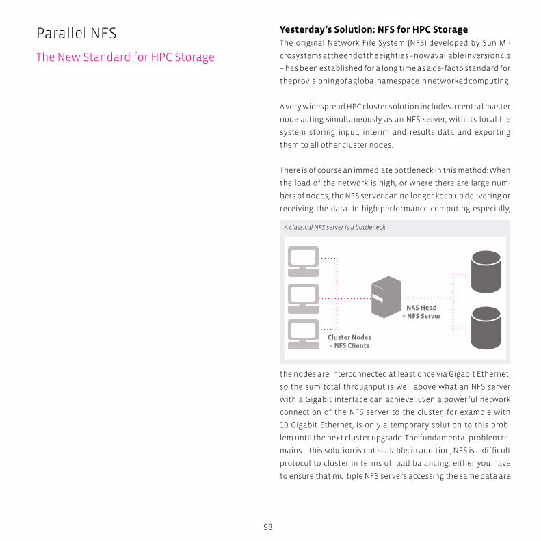
Cluster Nodes= NFS Clients
NAS Head= NFS Server
98
Parallel NFS
The New Standard for HPC Storage
Yesterday’s Solution: NFS for HPC StorageThe original Network File System (NFS) developed by Sun Mi-
crosystems at the end of the eighties – now available in version 4.1
– has been established for a long time as a de-facto standard for
the provisioning of a global namespace in networked computing.
A very widespread HPC cluster solution includes a central master
node acting simultaneously as an NFS server, with its local file
system storing input, interim and results data and exporting
them to all other cluster nodes.
There is of course an immediate bottleneck in this method: When
the load of the network is high, or where there are large num-
bers of nodes, the NFS server can no longer keep up delivering or
receiving the data. In high-performance computing especially,
the nodes are interconnected at least once via Gigabit Ethernet,
so the sum total throughput is well above what an NFS server
with a Gigabit interface can achieve. Even a powerful network
connection of the NFS server to the cluster, for example with
10-Gigabit Ethernet, is only a temporary solution to this prob-
lem until the next cluster upgrade. The fundamental problem re-
mains – this solution is not scalable; in addition, NFS is a difficult
protocol to cluster in terms of load balancing: either you have
to ensure that multiple NFS servers accessing the same data are
A classical NFS server is a bottleneck
99
constantly synchronised, the disadvantage being a noticeable
drop in performance or you manually partition the global name-
space which is also time-consuming. NFS is not suitable for dy-
namic load balancing as on paper it appears to be stateless but
in reality is, in fact, stateful.
Today’s Solution: Parallel File SystemsFor some time, powerful commercial products have been
available to meet the high demands on an HPC storage sys-
tem. The open-source solutions BeeGFS from the Fraunhofer
Competence Center for High Performance Computing or Lus-
tre are widely used in the Linux HPC world, and also several
other free as well as commercial parallel file system solutions
exist.
What is new is that the time-honoured NFS is to be upgraded,
including a parallel version, into an Internet Standard with
the aim of interoperability between all operating systems.
The original problem statement for parallel NFS access was
written by Garth Gibson, a professor at Carnegie Mellon Uni-
versity and founder and CTO of Panasas. Gibson was already a
renowned figure being one of the authors contributing to the
original paper on RAID architecture from 1988.
The original statement from Gibson and Panasas is clearly no-
ticeable in the design of pNFS. The powerful HPC file system
developed by Gibson and Panasas, ActiveScale PanFS, with
object-based storage devices functioning as central compo-
nents, is basically the commercial continuation of the “Net-
work-Attached Secure Disk (NASD)” project also developed by
Garth Gibson at the Carnegie Mellon University.
Parallel NFSParallel NFS (pNFS) is gradually emerging as the future standard
to meet requirements in the HPC environment. From the indus-
try’s as well as the user’s perspective, the benefits of utilising
standard solutions are indisputable: besides protecting end
user investment, standards also ensure a defined level of inter-
operability without restricting the choice of products availa-
ble. As a result, less user and administrator training is required
which leads to simpler deployment and at the same time, a
greater acceptance.
As part of the NFS 4.1 Internet Standard, pNFS will not only
adopt the semantics of NFS in terms of cache consistency or
security, it also represents an easy and flexible extension of
the NFS 4 protocol. pNFS is optional, in other words, NFS 4.1 im-
plementations do not have to include pNFS as a feature. The
scheduled Internet Standard NFS 4.1 is today presented as IETF
RFC 5661.
The pNFS protocol supports a separation of metadata and data:
a pNFS cluster comprises so-called storage devices which store
the data from the shared file system and a metadata server
(MDS), called Director Blade with Panasas – the actual NFS 4.1
server. The metadata server keeps track of which data is stored
on which storage devices and how to access the files, the so-
called layout. Besides these “striping parameters”, the MDS
also manages other metadata including access rights or similar,
which is usually stored in a file’s inode.
The layout types define which Storage Access Protocol is used
by the clients to access the storage devices. Up until now, three
potential storage access protocols have been defined for pNFS:
file, block and object-based layouts, the former being described
in RFC 5661 direct, the latters in RFC 5663 and 5664, respective-
ly. Last but not least, a Control Protocol is also used by the MDS
and storage devices to synchronise status data. This protocol is
deliberately unspecified in the standard to give manufacturers
certain flexibility. The NFS 4.1 standard does however specify cer-
tain conditions which a control protocol has to fulfil, for exam-
ple, how to deal with the change/modify time attributes of files.
S
N
EW
SESW
NENW
tech BOX
100
Parallel NFS
What’s New in NFS 4.1?
What’s New in NFS 4.1?NFS 4.1 is a minor update to NFS 4, and adds new features to it.
One of the optional features is parallel NFS (pNFS) but there is
other new functionality as well.
One of the technical enhancements is the use of sessions, a
persistent server object, dynamically created by the client. By
means of sessions, the state of an NFS connection can be stored,
no matter whether the connection is live or not. Sessions sur-
vive temporary downtimes both of the client and the server.
Each session has a so-called fore channel, which is the connec-
tion from the client to the server for all RPC operations, and op-
tionally a back channel for RPC callbacks from the server that
now can also be realized through firewall boundaries. Sessions
can be trunked to increase the bandwidth. Besides session
trunking there is also a client ID trunking for grouping together
several sessions to the same client ID.
By means of sessions, NFS can be seen as a really stateful proto-
col with a so-called “Exactly-Once Semantics (EOS)”. Until now, a
necessary but unspecified reply cache within the NFS server is
implemented to handle identical RPC operations that have been
sent several times. This statefulness in reality is not very robust,
however, and sometimes leads to the well-known stale NFS han-
dles. In NFS 4.1, the reply cache is now a mandatory part of the
NFS implementation, storing the server replies to RPC requests
persistently on disk.
101
Another new feature of NFS 4.1 is delegation for directories: NFS
clients can be given temporary exclusive access to directories.
Before, this has only been possible for simple files. With the
forthcoming version 4.2 of the NFS standard, federated filesys-
tems will be added as a feature, which represents the NFS coun-
terpart of Microsoft’s DFS (distributed filesystem).
Some Proposed NFSv4.2 featuresNFSv4.2 promises many features that end-users have been
requesting, and that makes NFS more relevant as not only an
“every day” protocol, but one that has application beyond the
data center.
Server Side Copy
Server-Side Copy (SSC) removes one leg of a copy operation. In-
stead of reading entire files or even directories of files from one
server through the client, and then writing them out to another,
SSC permits the destination server to communicate directly to
the source server without client involvement, and removes the
limitations on server to client bandwidth and the possible con-
gestion it may cause.
Application Data Blocks (ADB)
ADB allows definition of the format of a file; for example, a VM
image or a database. This feature will allow initialization of data
stores; a single operation from the client can create a 300GB da-
tabase or a VM image on the server.
Guaranteed Space Reservation & Hole Punching
As storage demands continue to increase, various efficiency
techniques can be employed to give the appearance of a large
virtual pool of storage on a much smaller storage system. Thin
provisioning, (where space appears available and reserved, but
is not committed) is commonplace, but often problematic to
manage in fast growing environments. The guaranteed space
reservation feature in NFSv4.2 will ensure that, regardless of the
thin provisioning policies, individual files will always have space
vailable for their maximum extent.
While such guarantees are a reassurance for the end-user, they
don’t help the storage administrator in his or her desire to fully
utilize all his available storage. In support of better storage ef-
ficiencies, NFSv4.2 will introduce support for sparse files. Com-
monly called “hole punching”, deleted and unused parts of files
are returned to the storage system’s free space pool.
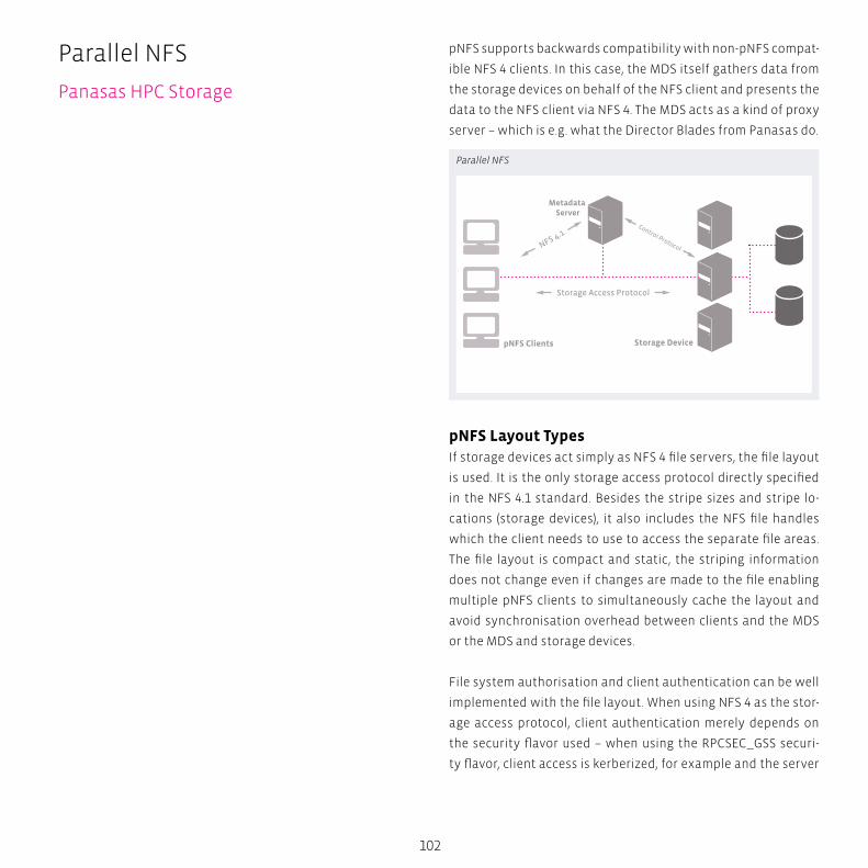
pNFS Clients Storage Device
Metadata Server
Storage Access Protocol
NFS 4.1Control Protocol
102
pNFS supports backwards compatibility with non-pNFS compat-
ible NFS 4 clients. In this case, the MDS itself gathers data from
the storage devices on behalf of the NFS client and presents the
data to the NFS client via NFS 4. The MDS acts as a kind of proxy
server – which is e.g. what the Director Blades from Panasas do.
pNFS Layout TypesIf storage devices act simply as NFS 4 file servers, the file layout
is used. It is the only storage access protocol directly specified
in the NFS 4.1 standard. Besides the stripe sizes and stripe lo-
cations (storage devices), it also includes the NFS file handles
which the client needs to use to access the separate file areas.
The file layout is compact and static, the striping information
does not change even if changes are made to the file enabling
multiple pNFS clients to simultaneously cache the layout and
avoid synchronisation overhead between clients and the MDS
or the MDS and storage devices.
File system authorisation and client authentication can be well
implemented with the file layout. When using NFS 4 as the stor-
age access protocol, client authentication merely depends on
the security flavor used – when using the RPCSEC_GSS securi-
ty flavor, client access is kerberized, for example and the server
Parallel NFS
Panasas HPC Storage
Parallel NFS
103
controls access authorization using specified ACLs and cryp-
tographic processes.
In contrast, the block/volume layout uses volume identifiers
and block offsets and extents to specify a file layout. SCSI
block commands are used to access storage devices. As the
block distribution can change with each write access, the
layout must be updated more frequently than with the file
layout.
Block-based access to storage devices does not offer any secure
authentication option for the accessing SCSI initiator. Secure
SAN authorisation is possible with host granularity only, based
on World Wide Names (WWNs) with Fibre Channel or Initiator
Node Names (IQNs) with iSCSI. The server cannot enforce access
control governed by the file system. On the contrary, a pNFS
client basically voluntarily abides with the access rights, the
storage device has to trust the pNFS client – a fundamental
access control problem that is a recurrent issue in the NFS pro-
tocol history.
The object layout is syntactically similar to the file layout, but it
uses the SCSI object command set for data access to so-called
Object-based Storage Devices (OSDs) and is heavily based on
the DirectFLOW protocol of the ActiveScale PanFS from Pana-
sas. From the very start, Object-Based Storage Devices were
designed for secure authentication and access. So-called capa-
bilities are used for object access which involves the MDS issu-
ing so-called capabilities to the pNFS clients. The ownership of
these capabilities represents the authoritative access right to
an object.
pNFS can be upgraded to integrate other storage access pro-
tocols and operating systems, and storage manufacturers also
have the option to ship additional layout drivers for their pNFS
implementations.
The Panasas file system uses parallel and redundant access to
object storage devices (OSDs), per-file RAID, distributed metada-
ta management, consistent client caching, file locking services,
and internal cluster management to provide a scalable, fault tol-
erant, high performance distributed file system.
The clustered design of the storage system and the use of cli-
ent-driven RAID provide scalable performance to many concur-
rent file system clients through parallel access to file data that
is striped across OSD storage nodes. RAID recovery is performed
in parallel by the cluster of metadata managers, and declus-
tered data placement yields scalable RAID rebuild rates as the
storage system grows larger.
Panasas HPC StoragePanasas ActiveStor parallel storage takes a very different ap-
proach by allowing compute clients to read and write directly
to the storage, entirely eliminating filer head bottlenecks and
allowing single file system capacity and performance to scale
linearly to extreme levels using a proprietary protocol called Di-
rectFlow. Panasas has actively shared its core knowledge with
a consortium of storage industry technology leaders to create
an industry standard protocol which will eventually replace the
need for DirectFlow. This protocol, called parallel NFS (pNFS) is
now an optional extension of the NFS v4.1 standard.
The Panasas system is a production system that provides file
service to some of the largest compute clusters in the world, in
scientific labs, in seismic data processing, in digital animation
studios, in computational fluid dynamics, in semiconductor
manufacturing, and in general purpose computing environ-
ments. In these environments, hundreds or thousands of file
system clients share data and generate very high aggregate I/O
load on the file system. The Panasas system is designed to sup-
port several thousand clients and storage capacities in excess
of a petabyte.
BOX
104
Parallel NFS
Panasas HPC Storage
Having a many years’ experience in deploying parallel file sys-
tems like Lustre or BeeGFS from smaller scales up to hundreds
of terabytes capacity and throughputs of several gigabytes
per second, transtec chose Panasas, the leader in HPC storage
solutions, as the partner for providing highest performance and
scalability on the one hand, and ease of management on the
other.
Therefore, with Panasas as the technology leader, and tran-
stec’s overall experience and customer-oriented approach,
customers can be assured to get the best possible HPC storage
solution available.
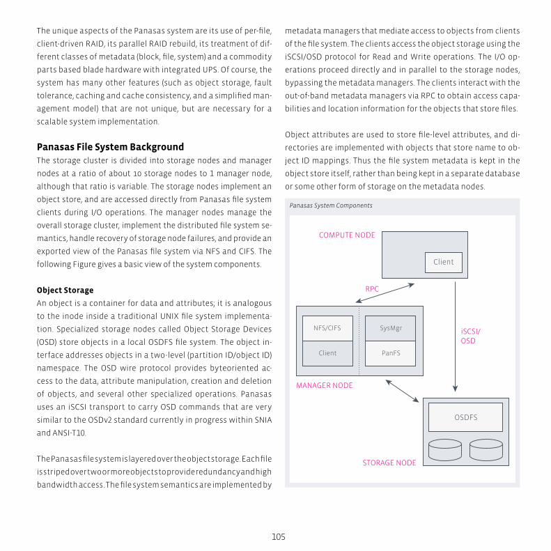
NFS/CIFS
OSDFS
SysMgr
COMPUTE NODE
MANAGER NODE
STORAGE NODE
iSCSI/OSD
PanFSClient
RPC
Client
105
The unique aspects of the Panasas system are its use of per-file,
client-driven RAID, its parallel RAID rebuild, its treatment of dif-
ferent classes of metadata (block, file, system) and a commodity
parts based blade hardware with integrated UPS. Of course, the
system has many other features (such as object storage, fault
tolerance, caching and cache consistency, and a simplified man-
agement model) that are not unique, but are necessary for a
scalable system implementation.
Panasas File System BackgroundThe storage cluster is divided into storage nodes and manager
nodes at a ratio of about 10 storage nodes to 1 manager node,
although that ratio is variable. The storage nodes implement an
object store, and are accessed directly from Panasas file system
clients during I/O operations. The manager nodes manage the
overall storage cluster, implement the distributed file system se-
mantics, handle recovery of storage node failures, and provide an
exported view of the Panasas file system via NFS and CIFS. The
following Figure gives a basic view of the system components.
Object Storage
An object is a container for data and attributes; it is analogous
to the inode inside a traditional UNIX file system implementa-
tion. Specialized storage nodes called Object Storage Devices
(OSD) store objects in a local OSDFS file system. The object in-
terface addresses objects in a two-level (partition ID/object ID)
namespace. The OSD wire protocol provides byteoriented ac-
cess to the data, attribute manipulation, creation and deletion
of objects, and several other specialized operations. Panasas
uses an iSCSI transport to carry OSD commands that are very
similar to the OSDv2 standard currently in progress within SNIA
and ANSI-T10.
The Panasas file system is layered over the object storage. Each file
is striped over two or more objects to provide redundancy and high
bandwidth access. The file system semantics are implemented by
metadata managers that mediate access to objects from clients
of the file system. The clients access the object storage using the
iSCSI/OSD protocol for Read and Write operations. The I/O op-
erations proceed directly and in parallel to the storage nodes,
bypassing the metadata managers. The clients interact with the
out-of-band metadata managers via RPC to obtain access capa-
bilities and location information for the objects that store files.
Object attributes are used to store file-level attributes, and di-
rectories are implemented with objects that store name to ob-
ject ID mappings. Thus the file system metadata is kept in the
object store itself, rather than being kept in a separate database
or some other form of storage on the metadata nodes.
Panasas System Components

106
Parallel NFS
Panasas HPC Storage
System Software Components
The major software subsystems are the OSDFS object storage
system, the Panasas file system metadata manager, the Pana-
sas file system client, the NFS/CIFS gateway, and the overall
cluster management system.
� The Panasas client is an installable kernel module that runs in-
side the Linux kernel. The kernel module implements the stand-
ard VFS interface, so that the client hosts can mount the file sys-
tem and use a POSIX interface to the storage system.
� Each storage cluster node runs a common platform that is based
on FreeBSD, with additional services to provide hardware moni-
toring, configuration management, and overall control.
� The storage nodes use a specialized local file system (OSD-
FS) that implements the object storage primitives. They
implement an iSCSI target and the OSD command set. The
OSDFS object store and iSCSI target/OSD command proces-
sor are kernel modules. OSDFS is concerned with traditional
block-level file system issues such as efficient disk arm utili-
zation, media management (i.e. error handling), high through-
put, as well as the OSD interface.
� The cluster manager (SysMgr) maintains the global configura-
tion, and it controls the other services and nodes in the storage
cluster. There is an associated management application that pro-
vides both a command line interface (CLI) and an HTML interface
(GUI). These are all user level applications that run on a subset
of the manager nodes. The cluster manager is concerned with
membership in the storage cluster, fault detection, configuration
management, and overall control for operations like software
upgrade and system restart.
� The Panasas metadata manager (PanFS) implements the file
system semantics and manages data striping across the object
storage devices. This is a user level application that runs on every
manager node. The metadata manager is concerned with distrib-
uted file system issues such as secure multi-user access, main-
taining consistent file- and object-level metadata, client cache
coherency, and recovery from client, storage node, and metadata
107
server crashes. Fault tolerance is based on a local transaction log
that is replicated to a backup on a different manager node.
� The NFS and CIFS services provide access to the file system
for hosts that cannot use our Linux installable file system
client. The NFS service is a tuned version of the standard
FreeBSD NFS server that runs inside the kernel. The CIFS ser-
vice is based on Samba and runs at user level. In turn, these
services use a local instance of the file system client, which
runs inside the FreeBSD kernel. These gateway services run
on every manager node to provide a clustered NFS and CIFS
service.
Commodity Hardware Platform
The storage cluster nodes are implemented as blades that are
very compact computer systems made from commodity parts.
The blades are clustered together to provide a scalable plat-
form. The OSD StorageBlade module and metadata manager Di-
rectorBlade module use the same form factor blade and fit into
the same chassis slots.
Storage Management
Traditional storage management tasks involve partitioning
available storage space into LUNs (i.e., logical units that are one
or more disks, or a subset of a RAID array), assigning LUN own-
ership to different hosts, configuring RAID parameters, creating
file systems or databases on LUNs, and connecting clients to the
correct server for their storage. This can be a labor-intensive sce-
nario. Panasas provides a simplified model for storage manage-
ment that shields the storage administrator from these kinds of
details and allow a single, part-time admin to manage systems
that were hundreds of terabytes in size.
The Panasas storage system presents itself as a file system with
a POSIX interface, and hides most of the complexities of storage
management. Clients have a single mount point for the entire
system. The /etc/fstab file references the cluster manager, and
from that the client learns the location of the metadata service
instances. The administrator can add storage while the system
is online, and new resources are automatically discovered. To
manage available storage, Panasas introduces two basic stor-
age concepts: a physical storage pool called a BladeSet, and a
logical quota tree called a Volume. The BladeSet is a collection
of StorageBlade modules in one or more shelves that comprise a
RAID fault domain. Panasas mitigates the risk of large fault do-
mains with the scalable rebuild performance described below
in the text. The BladeSet is a hard physical boundary for the vol-
umes it contains. A BladeSet can be grown at any time, either by
adding more StorageBlade modules, or by merging two existing
BladeSets together.
The Volume is a directory hierarchy that has a quota constraint
and is assigned to a particular BladeSet. The quota can be
changed at any time, and capacity is not allocated to the Vol-
ume until it is used, so multiple volumes compete for space
within their BladeSet and grow on demand. The files in those
volumes are distributed among all the StorageBlade modules
in the BladeSet. Volumes appear in the file system name space
as directories. Clients have a single mount point for the whole
storage system, and volumes are simply directories below the
mount point. There is no need to update client mounts when the
admin creates, deletes, or renames volumes.
Automatic Capacity Balancing
Capacity imbalance occurs when expanding a BladeSet (i.e., add-
ing new, empty storage nodes), merging two BladeSets, and re-
placing a storage node following a failure. In the latter scenario,
the imbalance is the result of the RAID rebuild, which uses spare
capacity on every storage node rather than dedicating a specif-
ic “hot spare” node. This provides better throughput during re-
build, but causes the system to have a new, empty storage node
after the failed storage node is replaced. The system automati-
cally balances used capacity across storage nodes in a BladeSet
108
Parallel NFS
Panasas HPC Storage
using two mechanisms: passive balancing and active balancing.
Passive balancing changes the probability that a storage node
will be used for a new component of a file, based on its availa-
ble capacity. This takes effect when files are created, and when
their stripe size is increased to include more storage nodes. Ac-
tive balancing is done by moving an existing component object
from one storage node to another, and updating the storage
map for the affected file. During the transfer, the file is transpar-
ently marked read-only by the storage management layer, and
the capacity balancer skips files that are being actively written.
Capacity balancing is thus transparent to file system clients.
Object RAID and ReconstructionPanasas protects against loss of a data object or an entire stor-
age node by striping files across objects stored on different
storage nodes, using a fault-tolerant striping algorithm such as
RAID-1 or RAID-5. Small files are mirrored on two objects, and
larger files are striped more widely to provide higher bandwidth
and less capacity overhead from parity information. The per-file
RAID layout means that parity information for different files is
not mixed together, and easily allows different files to use differ-
ent RAID schemes alongside each other. This property and the
security mechanisms of the OSD protocol makes it possible to
enforce access control over files even as clients access storage
nodes directly. It also enables what is perhaps the most novel
aspect of our system, client-driven RAID. That is, the clients are
responsible for computing and writing parity. The OSD security
mechanism also allows multiple metadata managers to manage
objects on the same storage device without heavyweight coor-
dination or interference from each other.
Client-driven, per-file RAID has four advantages for large-scale
storage systems. First, by having clients compute parity for
their own data, the XOR power of the system scales up as the
number of clients increases. We measured XOR processing dur-
ing streaming write bandwidth loads at 7% of the client’s CPU,
©2013 Panasas Incorporated. All rights reserved. Panasas,
the Panasas logo, Accelerating Time to Results, ActiveScale,
DirectFLOW, DirectorBlade, StorageBlade, PanFS, PanActive
and MyPanasas are trademarks or registered trademarks of
Panasas, Inc. in the United States and other countries. All oth-
er trademarks are the property of their respective owners.
Information supplied by Panasas, Inc. is believed to be accu-
rate and reliable at the time of publication, but Panasas, Inc.
assumes no responsibility for any errors that may appear in
this document. Panasas, Inc. reserves the right, without no-
tice, to make changes in product design, specifications and
prices. Information is subject to change without notice.
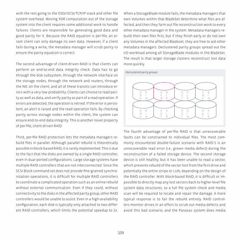
bCf
hJK
CDe
Gim
ADe
him
ACD
GJK
bCf
Gim
Aef
hJK
bDe
Gim
Abf
hjK
109
with the rest going to the OSD/iSCSI/TCP/IP stack and other file
system overhead. Moving XOR computation out of the storage
system into the client requires some additional work to handle
failures. Clients are responsible for generating good data and
good parity for it. Because the RAID equation is per-file, an er-
rant client can only damage its own data. However, if a client
fails during a write, the metadata manager will scrub parity to
ensure the parity equation is correct.
The second advantage of client-driven RAID is that clients can
perform an end-to-end data integrity check. Data has to go
through the disk subsystem, through the network interface on
the storage nodes, through the network and routers, through
the NIC on the client, and all of these transits can introduce er-
rors with a very low probability. Clients can choose to read pari-
ty as well as data, and verify parity as part of a read operation. If
errors are detected, the operation is retried. If the error is persis-
tent, an alert is raised and the read operation fails. By checking
parity across storage nodes within the client, the system can
ensure end-to-end data integrity. This is another novel property
of per-file, client-driven RAID.
Third, per-file RAID protection lets the metadata managers re-
build files in parallel. Although parallel rebuild is theoretically
possible in block-based RAID, it is rarely implemented. This is due
to the fact that the disks are owned by a single RAID controller,
even in dual-ported configurations. Large storage systems have
multiple RAID controllers that are not interconnected. Since the
SCSI Block command set does not provide fine-grained synchro-
nization operations, it is difficult for multiple RAID controllers
to coordinate a complicated operation such as an online rebuild
without external communication. Even if they could, without
connectivity to the disks in the affected parity group, other RAID
controllers would be unable to assist. Even in a high-availability
configuration, each disk is typically only attached to two differ-
ent RAID controllers, which limits the potential speedup to 2x.
When a StorageBlade module fails, the metadata managers that
own Volumes within that BladeSet determine what files are af-
fected, and then they farm out file reconstruction work to every
other metadata manager in the system. Metadata managers re-
build their own files first, but if they finish early or do not own
any Volumes in the affected Bladeset, they are free to aid other
metadata managers. Declustered parity groups spread out the
I/O workload among all StorageBlade modules in the BladeSet.
The result is that larger storage clusters reconstruct lost data
more quickly.
The fourth advantage of per-file RAID is that unrecoverable
faults can be constrained to individual files. The most com-
monly encountered double-failure scenario with RAID-5 is an
unrecoverable read error (i.e., grown media defect) during the
reconstruction of a failed storage device. The second storage
device is still healthy, but it has been unable to read a sector,
which prevents rebuild of the sector lost from the first drive and
potentially the entire stripe or LUN, depending on the design of
the RAID controller. With block-based RAID, it is difficult or im-
possible to directly map any lost sectors back to higher-level file
system data structures, so a full file system check and media
scan will be required to locate and repair the damage. A more
typical response is to fail the rebuild entirely. RAID control-
lers monitor drives in an effort to scrub out media defects and
avoid this bad scenario, and the Panasas system does media
Declustered parity groups
110
Parallel NFS
Panasas HPC Storage
scrubbing, too. However, with high capacity SATA drives, the
chance of encountering a media defect on drive B while rebuild-
ing drive A is still significant. With per-file RAID-5, this sort of
double failure means that only a single file is lost, and the spe-
cific file can be easily identified and reported to the administra-
tor. While block-based RAID systems have been compelled to
introduce RAID-6 (i.e., fault tolerant schemes that handle two
failures), the Panasas solution is able to deploy highly reliable
RAID-5 systems with large, high performance storage pools.
RAID Rebuild Performance
RAID rebuild performance determines how quickly the system
can recover data when a storage node is lost. Short rebuild
times reduce the window in which a second failure can cause
data loss. There are three techniques to reduce rebuild times: re-
ducing the size of the RAID parity group, declustering the place-
ment of parity group elements, and rebuilding files in parallel
using multiple RAID engines.
The rebuild bandwidth is the rate at which reconstructed data
is written to the system when a storage node is being recon-
structed. The system must read N times as much as it writes,
depending on the width of the RAID parity group, so the overall
throughput of the storage system is several times higher than
the rebuild rate. A narrower RAID parity group requires fewer
read and XOR operations to rebuild, so will result in a higher re-
build bandwidth.
However, it also results in higher capacity overhead for parity
data, and can limit bandwidth during normal I/O. Thus, selection
of the RAID parity group size is a trade-off between capacity
overhead, on-line performance, and rebuild performance. Un-
derstanding declustering is easier with a picture. In the figure
on the left, each parity group has 4 elements, which are indicat-
ed by letters placed in each storage device. They are distributed
among 8 storage devices. The ratio between the parity group
size and the available storage devices is the declustering ratio,
111
which in this example is ½. In the picture, capital letters repre-
sent those parity groups that all share the second storage node.
If the second storage device were to fail, the system would have
to read the surviving members of its parity groups to rebuild
the lost elements. You can see that the other elements of those
parity groups occupy about ½ of each other storage device. For
this simple example you can assume each parity element is the
same size so all the devices are filled equally. In a real system,
the component objects will have various sizes depending on the
overall file size, although each member of a parity group will be
very close in size. There will be thousands or millions of objects
on each device, and the Panasas system uses active balancing
to move component objects between storage nodes to level ca-
pacity. Declustering means that rebuild requires reading a sub-
set of each device, with the proportion being approximately the
same as the declustering ratio. The total amount of data read is
the same with and without declustering, but with declustering
it is spread out over more devices. When writing the reconstruct-
ed elements, two elements of the same parity group cannot be
located on the same storage node. Declustering leaves many
storage devices available for the reconstructed parity element,
and randomizing the placement of each file’s parity group lets
the system spread out the write I/O over all the storage. Thus
declustering RAID parity groups has the important property of
taking a fixed amount of rebuild I/O and spreading it out over
more storage devices.
Having per-file RAID allows the Panasas system to divide the
work among the available DirectorBlade modules by assigning
different files to different DirectorBlade modules. This division
is dynamic with a simple master/worker model in which meta-
data services make themselves available as workers, and each
metadata service acts as the master for the volumes it imple-
ments. By doing rebuilds in parallel on all DirectorBlade mod-
ules, the system can apply more XOR throughput and utilize the
additional I/O bandwidth obtained with declustering.
Metadata ManagementThere are several kinds of metadata in the Panasas system.
These include the mapping from object IDs to sets of block ad-
dresses, mapping files to sets of objects, file system attributes
such as ACLs and owners, file system namespace information
(i.e., directories), and configuration/management information
about the storage cluster itself.
Block-level Metadata
Block-level metadata is managed internally by OSDFS, the file
system that is optimized to store objects. OSDFS uses a floating
block allocation scheme where data, block pointers, and object
descriptors are batched into large write operations. The write
buffer is protected by the integrated UPS, and it is flushed to
disk on power failure or system panics. Fragmentation was an
issue in early versions of OSDFS that used a first-fit block allo-
cator, but this has been significantly mitigated in later versions
that use a modified best-fit allocator.
OSDFS stores higher level file system data structures, such as
the partition and object tables, in a modified BTree data struc-
ture. Block mapping for each object uses a traditional direct/
indirect/double-indirect scheme. Free blocks are tracked by
a proprietary bitmap-like data structure that is optimized for
copy-on-write reference counting, part of OSDFS’s integrated
support for object- and partition-level copy-on-write snapshots.
Block-level metadata management consumes most of the cycles
in file system implementations. By delegating storage manage-
ment to OSDFS, the Panasas metadata managers have an or-
der of magnitude less work to do than the equivalent SAN file
system metadata manager that must track all the blocks in the
system.
File-level Metadata
Above the block layer is the metadata about files. This includes
user-visible information such as the owner, size, and modification
112
Parallel NFS
Panasas HPC Storage
time, as well as internal information that identifies which ob-
jects store the file and how the data is striped across those
objects (i.e., the file’s storage map). Our system stores this file
metadata in object attributes on two of the N objects used to
store the file’s data. The rest of the objects have basic attrib-
utes like their individual length and modify times, but the high-
er-level file system attributes are only stored on the two attrib-
ute-storing components.
File names are implemented in directories similar to traditional
UNIX file systems. Directories are special files that store an array
of directory entries. A directory entry identifies a file with a tuple
of <serviceID, partitionID, objectID>, and also includes two <os-
dID> fields that are hints about the location of the attribute stor-
ing components. The partitionID/objectID is the two-level ob-
ject numbering scheme of the OSD interface, and Panasas uses
a partition for each volume. Directories are mirrored (RAID-1)
in two objects so that the small write operations associated
with directory updates are efficient.
Clients are allowed to read, cache and parse directories, or they
can use a Lookup RPC to the metadata manager to translate
a name to an <serviceID, partitionID, objectID> tuple and the
<osdID> location hints. The serviceID provides a hint about the
metadata manager for the file, although clients may be redirect-
ed to the metadata manager that currently controls the file.
The osdID hint can become out-of-date if reconstruction or
active balancing moves an object. If both osdID hints fail, the
metadata manager has to multicast a GetAttributes to the stor-
age nodes in the BladeSet to locate an object. The partitionID
and objectID are the same on every storage node that stores a
component of the file, so this technique will always work. Once
the file is located, the metadata manager automatically updates
the stored hints in the directory, allowing future accesses to by-
pass this step.
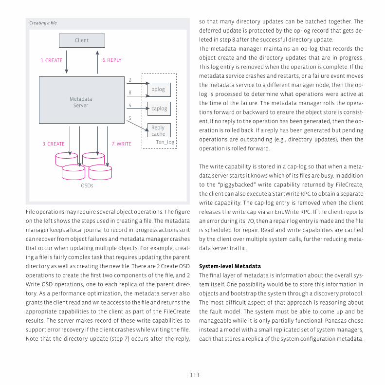
OSDs
1. CREATE
7. WRITE3. CREATE
MetadataServer
6. REPLY
Client
Txn_log
2
8
4
5
oplog
caplog
Replycache
113
File operations may require several object operations. The figure
on the left shows the steps used in creating a file. The metadata
manager keeps a local journal to record in-progress actions so it
can recover from object failures and metadata manager crashes
that occur when updating multiple objects. For example, creat-
ing a file is fairly complex task that requires updating the parent
directory as well as creating the new file. There are 2 Create OSD
operations to create the first two components of the file, and 2
Write OSD operations, one to each replica of the parent direc-
tory. As a performance optimization, the metadata server also
grants the client read and write access to the file and returns the
appropriate capabilities to the client as part of the FileCreate
results. The server makes record of these write capabilities to
support error recovery if the client crashes while writing the file.
Note that the directory update (step 7) occurs after the reply,
so that many directory updates can be batched together. The
deferred update is protected by the op-log record that gets de-
leted in step 8 after the successful directory update.
The metadata manager maintains an op-log that records the
object create and the directory updates that are in progress.
This log entry is removed when the operation is complete. If the
metadata service crashes and restarts, or a failure event moves
the metadata service to a different manager node, then the op-
log is processed to determine what operations were active at
the time of the failure. The metadata manager rolls the opera-
tions forward or backward to ensure the object store is consist-
ent. If no reply to the operation has been generated, then the op-
eration is rolled back. If a reply has been generated but pending
operations are outstanding (e.g., directory updates), then the
operation is rolled forward.
The write capability is stored in a cap-log so that when a meta-
data server starts it knows which of its files are busy. In addition
to the “piggybacked” write capability returned by FileCreate,
the client can also execute a StartWrite RPC to obtain a separate
write capability. The cap-log entry is removed when the client
releases the write cap via an EndWrite RPC. If the client reports
an error during its I/O, then a repair log entry is made and the file
is scheduled for repair. Read and write capabilities are cached
by the client over multiple system calls, further reducing meta-
data server traffic.
System-level Metadata
The final layer of metadata is information about the overall sys-
tem itself. One possibility would be to store this information in
objects and bootstrap the system through a discovery protocol.
The most difficult aspect of that approach is reasoning about
the fault model. The system must be able to come up and be
manageable while it is only partially functional. Panasas chose
instead a model with a small replicated set of system managers,
each that stores a replica of the system configuration metadata.
Creating a file
114
Parallel NFS
Panasas HPC Storage
Each system manager maintains a local database, outside of
the object storage system. Berkeley DB is used to store tables
that represent our system model. The different system manager
instances are members of a replication set that use Lamport’s
part-time parliament (PTP) protocol to make decisions and up-
date the configuration information. Clusters are configured with
one, three, or five system managers so that the voting quorum
has an odd number and a network partition will cause a minori-
ty of system managers to disable themselves.
System configuration state includes both static state, such
as the identity of the blades in the system, as well as dynam-
ic state such as the online/offline state of various services and
error conditions associated with different system components.
Each state update decision, whether it is updating the admin
password or activating a service, involves a voting round and an
update round according to the PTP protocol. Database updates
are performed within the PTP transactions to keep the data-
bases synchronized. Finally, the system keeps backup copies of
the system configuration databases on several other blades to
guard against catastrophic loss of every system manager blade.
Blade configuration is pulled from the system managers as part
of each blade’s startup sequence. The initial DHCP handshake
conveys the addresses of the system managers, and thereafter
the local OS on each blade pulls configuration information from
the system managers via RPC.
“Outstanding in the HPC world, the ActiveStor solutions provided by
Panasas are undoubtedly the only HPC storage solutions that com-
bine highest scalability and performance with a convincing ease of
management.“
Christoph Budziszewski HPC Solution Architect

115
The cluster manager implementation has two layers. The lower
level PTP layer manages the voting rounds and ensures that par-
titioned or newly added system managers will be brought up-to-
date with the quorum. The application layer above that uses the
voting and update interface to make decisions. Complex system
operations may involve several steps, and the system manager
has to keep track of its progress so it can tolerate a crash and
roll back or roll forward as appropriate.
For example, creating a volume (i.e., a quota-tree) involves file
system operations to create a top-level directory, object oper-
ations to create an object partition within OSDFS on each Stor-
ageBlade module, service operations to activate the appropri-
ate metadata manager, and configuration database operations
to reflect the addition of the volume.
Recovery is enabled by having two PTP transactions. The initial
PTP transaction determines if the volume should be created, and
it creates a record about the volume that is marked as incom-
plete. Then the system manager does all the necessary service
activations, file and storage operations. When these all com-
plete, a final PTP transaction is performed to commit the oper-
ation. If the system manager crashes before the final PTP trans-
action, it will detect the incomplete operation the next time
it restarts, and then roll the operation forward or backward.

BeeGFS – A Parallel File SystemBeeGFS is a highly flexible network file system, especially designed for scalability and
performance required by HPC systems.
It allows clients to communicate with storage servers via network (TCP/IP – or InfiniBand
with native VERBS support). Furthermore, BeeGFS is a parallel file system – by adding
more servers, the capacity and performance of them is aggregated in a single name-
space. That way the filesystem performance and capacity can be scaled to the level
which is required for HPC applications.
Life
Sci
en
ces
Ris
k A
na
lysi
s S
imu
lati
on
B
ig D
ata
An
aly
tics
H
igh
Pe
rfo
rma
nce
Co
mp
uti
ng
118
BeeGFS combines multiple storage servers to provide a highly
scalable shared network file system with striped file contents.
This way, it allows users to overcome the tight performance lim-
itations of single servers, single network interconnects, a limit-
ed number of hard drives etc. In such a system, high throughput
demands of large numbers of clients can easily be satisfied, but
even a single client can profit from the aggregated performance
of all the storage servers in the system.
Key Aspects:
� Maximum Flexibility
� BeeGFS supports a wide range of Linux distributions as well
as Linux kernels
� Storage servers run on top of an existing local file system
using the POSIX interface
� Clients and servers can be added to an existing system with-
out downtime
� BeeGFS supports multiple networks and dynamic failover
between different networks.
� BeeGFS provides support for metadata and file contents
mirroring
This is made possible by a separation of metadata and file con-
tents. While storage servers are responsible for storing stripes of
the actual contents of user files, metadata servers do the coordi-
nation of file placement and striping among the storage servers
and inform the clients about certain file details when necessary.
When accessing file contents, BeeGFS clients directly contact the
storage servers to perform file I/O and communicate with multi-
ple servers simultaneously, giving your applications truly paral-
lel access to the file data. To keep the metadata access latency
(e.g. directory lookups) at a minimum, BeeGFS allows you to also
distribute the metadata across multiple servers, so that each of
the metadata servers stores a part of the global file system name-
space.
BeeGFS
A Parallel File System
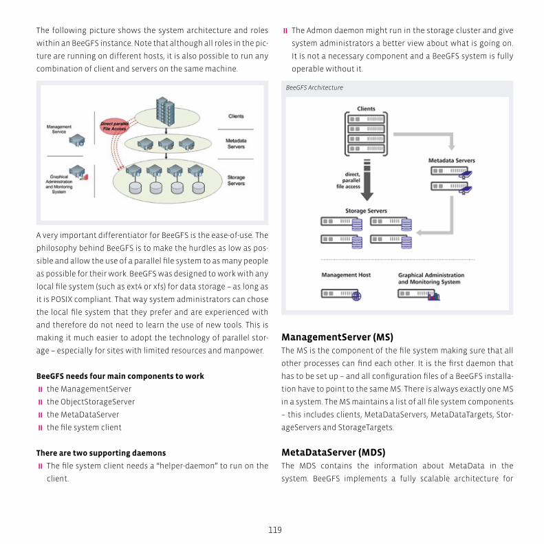
119
The following picture shows the system architecture and roles
within an BeeGFS instance. Note that although all roles in the pic-
ture are running on different hosts, it is also possible to run any
combination of client and servers on the same machine.
A very important differentiator for BeeGFS is the ease-of-use. The
philosophy behind BeeGFS is to make the hurdles as low as pos-
sible and allow the use of a parallel file system to as many people
as possible for their work. BeeGFS was designed to work with any
local file system (such as ext4 or xfs) for data storage – as long as
it is POSIX compliant. That way system administrators can chose
the local file system that they prefer and are experienced with
and therefore do not need to learn the use of new tools. This is
making it much easier to adopt the technology of parallel stor-
age – especially for sites with limited resources and manpower.
BeeGFS needs four main components to work
� the ManagementServer
� the ObjectStorageServer
� the MetaDataServer
� the file system client
There are two supporting daemons
� The file system client needs a “helper-daemon” to run on the
client.
� The Admon daemon might run in the storage cluster and give
system administrators a better view about what is going on.
It is not a necessary component and a BeeGFS system is fully
operable without it.
ManagementServer (MS)The MS is the component of the file system making sure that all
other processes can find each other. It is the first daemon that
has to be set up – and all configuration files of a BeeGFS installa-
tion have to point to the same MS. There is always exactly one MS
in a system. The MS maintains a list of all file system components
– this includes clients, MetaDataServers, MetaDataTargets, Stor-
ageServers and StorageTargets.
MetaDataServer (MDS)The MDS contains the information about MetaData in the
system. BeeGFS implements a fully scalable architecture for
BeeGFS Architecture

120
MetaData and allows a practically unlimited number of MDS.
Each MDS has exactly one MetaDataTarget (MDT). Each directory
in the global file system is attached to exactly one MDS handling
its content. Since the assignment of directories to MDS is random
BeeGFS can make efficient use of a (very) large number of MDS.
As long as the number of directories is significantly larger than
the number of MDS (which is normally the case), there will be a
roughly equal share of load on each of the MDS.
The MDS is a fully multithreaded daemon – the number of
threads to start has to be set to appropriate values for the used
hardware. Factors to consider here are number of CPU cores in
the MDS, number of Client, workload, number and type of disks
forming the MDT. So in general serving MetaData needs some
CPU power – and especially, if one wants to make use of fast un-
derlying storage like SSDs, the CPUs should not be too light to
avoid becoming the bottleneck.
ObjectStorageServer (OSS)The OSS is the main service to store the file contents. Each OSS
might have one or many ObjectStorageTargets (OST) – where
an OST is a RAID-Set (or LUN) with a local file system (such as xfs
or ext4) on top. A typical OST is between 6 and 12 hard drives in
RAID6 – so an OSS with 36 drives might be organized with 3 OSTs
each being a RAID6 with 12 drives.
The OSS is a user space daemon that is started on the appro-
priate machine. It will work with any local file system that
is POSIX compliant and supported by the Linux distribution.
The underlying file system may be picked according to the work-
load – or personal preference and experience.
BeeGFS
A Parallel File System
S
N
EW
SESW
NENW
tech BOX
121
Like the MDS, the OSS is a fully multithreaded daemon as well –
and so as with the MDS, the choice of the number of threads has
to be made with the underlying hardware in mind. The most im-
portant factor for the number of OSS-threads is the performance
and number of the OSTs that OSS is serving. In contradiction to
the MDS, the traffic on the OSTs should be (and normally is) to a
large extent sequential.
File System ClientBeeGFS comes with a native client that runs in Linux – it is a ker-
nel module that has to be compiled to match the used kernel. The
client is an open-source product made available under GPL. The
client has to be installed on all hosts that should access BeeGFS
with maximum performance.
The client needs two services to start:
fhgfs-helperd: This daemon provides certain auxiliary function-
alities for the fhgfs-client. The helperd does not require any
additional configuration – it is just accessed by the fhgfs-client
running on the same host. The helperd is mainly doing DNS for
the client kernel module and provides the capability to write the
logfile.
fhgfs-client: This service loads the client kernel module – if nec-
essary it will (re-)compile the kernel module. The recompile is
done using an automatic build process that is started when (for
example) the kernel version changes. This helps to make the file
system easy to use since, after applying a (minor or major) kernel
update, the BeeGFS client will still start up after a reboot, re-com-
pile and the file system will be available.
Striping One of the key functionalities of BeeGFS is called striping. In
a BeeGFS file system each directory has (amongst others) two
very important properties defining how files in these directo-
ries are handled.
Numtargets defines the number of targets a file is created
across. So if “4” is selected each file gets four OSTs assigned to
where the data of that file is stored to.
The chunksize on the other hand specifies, how much data is
stored on one assigned target before the client moves over to
the next target.
The goal of this striping of files is to improve the performance
for the single file as well as the available capacity. Assuming
that a target is 30 TB in size and can move data with 500 MB/s,
then a file across four targets can grow until 120 TB and be
accessed with 2 GB/s. Striping will allow you to store more
and store it faster!
122
Maximum Scalability � BeeGFS supports distributed file contents with flexible
striping across the storage servers as well as distributed
metadata
� Best in class client throughput of 3.5 GB/s write and 4.0 GB/s
read with a single I/O stream on FDR Infiniband
� Best in class metadata performance with linear scalability
through dynamic metadata namespace partitioning
� Best in class storage throughput with flexible choice of
underlying file system to perfectly fit the storage hardware.
Maximum UsabilityBeeGFS was designed with easy installation and admin-
istration in mind. BeeGFS requires no kernel patches (the
client is a patchless kernel module, the server components
are userspace daemons), comes with graphical cluster in-
stallation tools and allows you to add more clients and serv-
ers to the running system whenever you want it. The graph-
ical administration and monitoring system enables user to
handle typical management tasks in a intuitive way: cluster
installation, storage service management, live throughput and
health monitoring, file browsing, striping configuration and
more.
Features:
� Data and metadata for each file are separated into stripes and
distributed across the existing servers to aggregate server
speed
� Secure authentication process between client and server to
protect sensitive data
� Fair I/O option on user level to prevent a single user with mul-
tiple requests to stall other users request
� Automatic network failover, i.e. if Infiniband is down, BeeGFS
automatically uses Ethernet if available
� Optional server failover for external shared memory
resources - high availability
BeeGFS
A Parallel File System
„transtec has successfully deployed the first petabyte filesystem
with BeeGFS. And it is very impressive to see how BeeGFS combines
performance with reliability.”
Thomas Gebert HPC Solution Architect
BOX
123
transtec has an outstanding history of parallel filesystem im-
plementations since more than 12 years. Starting with some of
the first Lustre implementations, some of them extending to
nearly 1 Petabyte gross capacity, which constituted an enor-
mous size back 10 years ago, over to the deployment of many
enterprise-ready commercial solutions, we have now success-
fully deployed dozens of BeeGFS environment of various sizes.
In especial, transtec has been the first provider of a 1-peta-
byte-filesystem based on BeeGFS, then known as FraunhoferFS,
or FhGFS.
No matter what the customer’s requirements are: transtec has
knowledge in all parallel filesystem technologies and is able to
provide the customer with an individually sized and tailor-made
solution that meets their demands concerning capacity and per-
formance, and above all – because this is what customers take
as a matter of course – is stable and reliable at the same time.

124
� Runs on non-standard architectures, e.g. PowerPC or Intel
Xeon Phi
� Provides a coherent mode, in which it is guaranteed that
changes to a file or directory by one client are always immedi-
ately visible to other clients.
Performance:
BeeGFS was designed for extreme scalability. In a testbed with
20 servers and up to 640 client processes (32x the number of
metadata servers), BeeGFS delivers a sustained file creation rate
of more than 500,000 creates per second, making it possible to
create one billion files in as little time as about 30 minutes. In the
same testbed system with 20 servers - each equipped with a sin-
gle node local performance of 1332 MB/s (write) and 1317 MB/s
(read) – and 160 client processes, BeeGFS reached a sustained
throughput of 25 GB/s – which is 94.7 percent of the maximum
theoretical local write and 94.1 percent of the maximum theoret-
ical local read throughput.
BeeGFS
A Parallel File System
S
N
EW
SESW
NENW
tech BOX
125
MirroringBeeGFS provides support for metadata and file contents mirror-
ing. Mirroring capabilities are integrated into the normal BeeG-
FS services, so that no separate services or third-party tools are
needed. Both types of mirroring (metadata and file contents) can
be used independent of each other. The initial mirroring imple-
mentation enables data restore after a storage target or meta-
data server is lost. It does not provide failover or high availability
capabilites yet, so the file system will not automatically remain
accessible while a server is down. Those features will be added in
later FhGFS releases.
Mirroring can be enabled on a per-directory basis, so that some
data in the file system can be mirrored while other data might
not be mirrored. Primary servers/targets and mirror servers/tar-
gets are chosen individually for each new directory/file. Thus,
there are no passive (i.e. mirror-only) servers/targets in a file sys-
tem instance.
The granularity of metadata mirroring is a complete directory,
so that the entries of a single directory are always mirrored on
the same mirror server, but metadata for different directories is
mirrored on different metadata servers. The granularity of file
contents mirroring are individual files. Each file has its own set
of primary and mirror targets, even for files are in the same di-
rectory. Both types of mirroring can be used with an even or odd
number of servers or storage targets.
Metadata is mirrored asynchronously, i.e. the client operation
completes before the redundant copy has been transferred to
the mirror server. File contents are mirrored synchronously, i.e
the client operation completes after both copies of the data were
transferred to the servers. File contents mirroring is based on a
hybrid client- and server-side approach, where the client decides
whether it sends the mirror copy directly to the other server or
whether the storage server is responsible for forwarding of the
data to the mirror.
BeeGFS Dynamic FailoverBuilt on scalable multithreaded core components with native
Infiniband support, file system nodes can serve Infiniband and
Ethernet (or any other TCP-enabled network) connections at the
same time and automatically switch to a redundant connection
path in case any of them fails.

NVIDIA GPU Computing –The CUDA ArchitectureThe CUDA parallel computing platform is now widely deployed with 1000s of GPU-accel-
erated applications and 1000s of published research papers, and a complete range of
CUDA tools and ecosystem solutions is available to developers.
Hig
h T
rou
hp
ut
Co
mp
uti
ng
C
AD
B
ig D
ata
An
aly
tics
S
imu
lati
on
A
ero
spa
ce
Au
tom
oti
ve
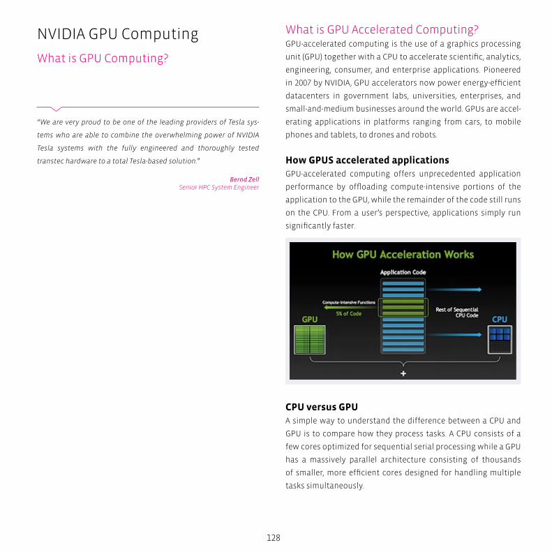
128
What is GPU Accelerated Computing?GPU-accelerated computing is the use of a graphics processing
unit (GPU) together with a CPU to accelerate scientific, analytics,
engineering, consumer, and enterprise applications. Pioneered
in 2007 by NVIDIA, GPU accelerators now power energy-efficient
datacenters in government labs, universities, enterprises, and
small-and-medium businesses around the world. GPUs are accel-
erating applications in platforms ranging from cars, to mobile
phones and tablets, to drones and robots.
How GPUS accelerated applications GPU-accelerated computing offers unprecedented application
performance by offloading compute-intensive portions of the
application to the GPU, while the remainder of the code still runs
on the CPU. From a user’s perspective, applications simply run
significantly faster.
CPU versus GPUA simple way to understand the difference between a CPU and
GPU is to compare how they process tasks. A CPU consists of a
few cores optimized for sequential serial processing while a GPU
has a massively parallel architecture consisting of thousands
of smaller, more efficient cores designed for handling multiple
tasks simultaneously.
NVIDIA GPU Computing
What is GPU Computing?
“We are very proud to be one of the leading providers of Tesla sys-
tems who are able to combine the overwhelming power of NVIDIA
Tesla systems with the fully engineered and thoroughly tested
transtec hardware to a total Tesla-based solution.”
Bernd ZellSenior HPC System Engineer
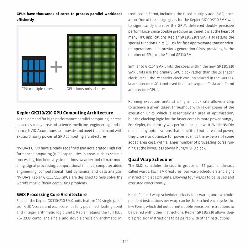
CPU multiple cores GPU thousands of cores
129
GPUs have thousands of cores to process parallel workloads
efficiently
Kepler GK110/210 GPU Computing Architecture As the demand for high performance parallel computing increas-
es across many areas of science, medicine, engineering, and fi-
nance, NVIDIA continues to innovate and meet that demand with
extraordinarily powerful GPU computing architectures.
NVIDIA’s GPUs have already redefined and accelerated High Per-
formance Computing (HPC) capabilities in areas such as seismic
processing, biochemistry simulations, weather and climate mod-
eling, signal processing, computational finance, computer aided
engineering, computational fluid dynamics, and data analysis.
NVIDIA’s Kepler GK110/210 GPUs are designed to help solve the
world’s most difficult computing problems.
SMX Processing Core ArchitectureEach of the Kepler GK110/210 SMX units feature 192 single-preci-
sion CUDA cores, and each core has fully pipelined floating-point
and integer arithmetic logic units. Kepler retains the full IEEE
754-2008 compliant single and double-precision arithmetic in-
troduced in Fermi, including the fused multiply-add (FMA) oper-
ation. One of the design goals for the Kepler GK110/210 SMX was
to significantly increase the GPU’s delivered double precision
performance, since double precision arithmetic is at the heart of
many HPC applications. Kepler GK110/210’s SMX also retains the
special function units (SFUs) for fast approximate transcenden-
tal operations as in previous-generation GPUs, providing 8x the
number of SFUs of the Fermi GF110 SM.
Similar to GK104 SMX units, the cores within the new GK110/210
SMX units use the primary GPU clock rather than the 2x shader
clock. Recall the 2x shader clock was introduced in the G80 Tes-
la architecture GPU and used in all subsequent Tesla and Fermi
architecture GPUs.
Running execution units at a higher clock rate allows a chip
to achieve a given target throughput with fewer copies of the
execution units, which is essentially an area of optimization,
but the clocking logic for the faster cores is more power-hungry.
For Kepler, the priority was performance per watt. While NVIDIA
made many optimizations that benefitted both area and power,
they chose to optimize for power even at the expense of some
added area cost, with a larger number of processing cores run-
ning at the lower, less power-hungry GPU clock.
Quad Warp Scheduler The SMX schedules threads in groups of 32 parallel threads
called warps. Each SMX features four warp schedulers and eight
instruction dispatch units, allowing four warps to be issued and
executed concurrently.
Kepler’s quad warp scheduler selects four warps, and two inde-
pendent instructions per warp can be dispatched each cycle. Un-
like Fermi, which did not permit double precision instructions to
be paired with other instructions, Kepler GK110/210 allows dou-
ble precision instructions to be paired with other instructions.
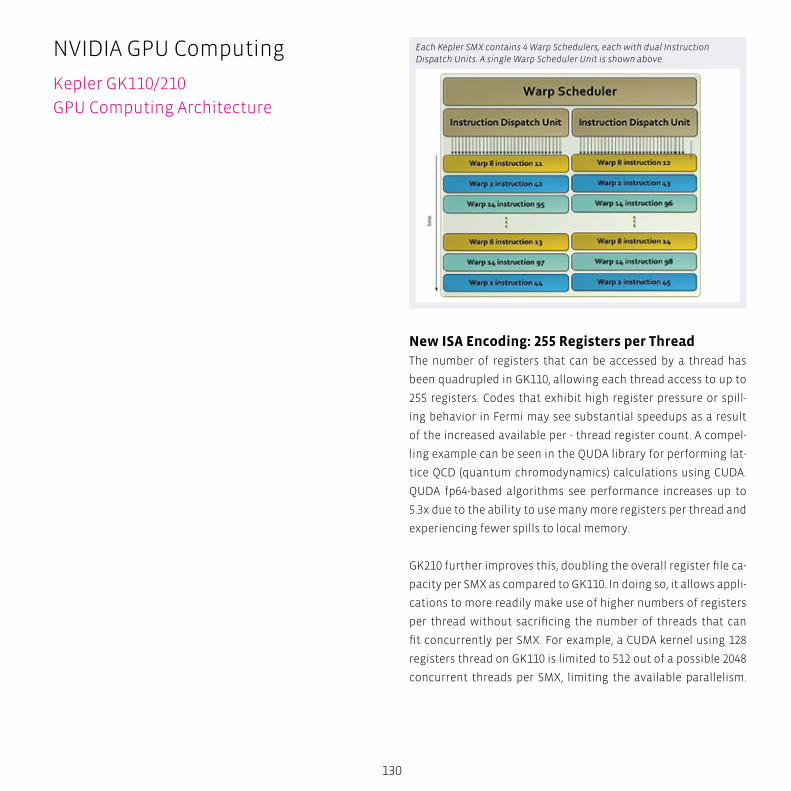
130
New ISA Encoding: 255 Registers per ThreadThe number of registers that can be accessed by a thread has
been quadrupled in GK110, allowing each thread access to up to
255 registers. Codes that exhibit high register pressure or spill-
ing behavior in Fermi may see substantial speedups as a result
of the increased available per - thread register count. A compel-
ling example can be seen in the QUDA library for performing lat-
tice QCD (quantum chromodynamics) calculations using CUDA.
QUDA fp64-based algorithms see performance increases up to
5.3x due to the ability to use many more registers per thread and
experiencing fewer spills to local memory.
GK210 further improves this, doubling the overall register file ca-
pacity per SMX as compared to GK110. In doing so, it allows appli-
cations to more readily make use of higher numbers of registers
per thread without sacrificing the number of threads that can
fit concurrently per SMX. For example, a CUDA kernel using 128
registers thread on GK110 is limited to 512 out of a possible 2048
concurrent threads per SMX, limiting the available parallelism.
NVIDIA GPU Computing
Kepler GK110/210
GPU Computing Architecture
Each Kepler SMX contains 4 Warp Schedulers, each with dual Instruction Dispatch Units. A single Warp Scheduler Unit is shown above.
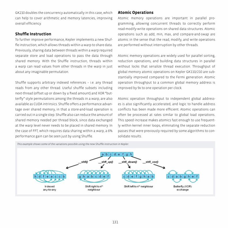
131
GK210 doubles the concurrency automatically in this case, which
can help to cover arithmetic and memory latencies, improving
overall efficiency.
Shuffle InstructionTo further improve performance, Kepler implements a new Shuf-
fle instruction, which allows threads within a warp to share data.
Previously, sharing data between threads within a warp required
separate store and load operations to pass the data through
shared memory. With the Shuffle instruction, threads within
a warp can read values from other threads in the warp in just
about any imaginable permutation.
Shuffle supports arbitrary indexed references – i.e. any thread
reads from any other thread. Useful shuffle subsets including
next-thread (offset up or down by a fixed amount) and XOR “but-
terfly” style permutations among the threads in a warp, are also
available as CUDA intrinsics. Shuffle offers a performance advan-
tage over shared memory, in that a store-and-load operation is
carried out in a single step. Shuffle also can reduce the amount of
shared memory needed per thread block, since data exchanged
at the warp level never needs to be placed in shared memory. In
the case of FFT, which requires data sharing within a warp, a 6%
performance gain can be seen just by using Shuffle.
Atomic OperationsAtomic memory operations are important in parallel pro-
gramming, allowing concurrent threads to correctly perform
read-modify-write operations on shared data structures. Atomic
operations such as add, min, max, and compare-and-swap are
atomic in the sense that the read, modify, and write operations
are performed without interruption by other threads.
Atomic memory operations are widely used for parallel sorting,
reduction operations, and building data structures in parallel
without locks that serialize thread execution. Throughput of
global memory atomic operations on Kepler GK110/210 are sub-
stantially improved compared to the Fermi generation. Atomic
operation throughput to a common global memory address is
improved by 9x to one operation per clock.
Atomic operation throughput to independent global address-
es is also significantly accelerated, and logic to handle address
conflicts has been made more efficient. Atomic operations can
often be processed at rates similar to global load operations.
This speed increase makes atomics fast enough to use frequent-
ly within kernel inner loops, eliminating the separate reduction
passes that were previously required by some algorithms to con-
solidate results.
This example shows some of the variations possible using the new Shuffle instruction in Kepler.
132
NVIDIA GPU Computing
Kepler GK110/210
GPU Computing Architecture
Kepler GK110 also expands the native support for 64-bit atomic
operations in global memory. In addition to atomicAdd, atomic-
CAS, and atomicExch (which were also supported by Fermi and
Kepler GK104), GK110 supports the following:
� atomicMin
� atomicMax
� atomicAnd
� atomicOr
� atomicXor
Other atomic operations which are not supported natively (for
example 64-bit floating point atomics) may be emulated using
the compare-and-swap (CAS) instruction.
Texture ImprovementsThe GPU’s dedicated hardware Texture units are a valuable re-
source for compute programs with a need to sample or filter
image data. The texture throughput in Kepler is significantly in-
creased compared to Fermi – each SMX unit contains 16 texture
filtering units, a 4x increase vs the Fermi GF110 SM.
In addition, Kepler changes the way texture state is managed. In
the Fermi generation, for the GPU to reference a texture, it had
to be assigned a “slot” in a fixed-size binding table prior to grid
launch.
The number of slots in that table ultimately limits how many
unique textures a program can read from at run time. Ultimately,
a program was limited to accessing only 128 simultaneous tex-
tures in Fermi.
With bindless textures in Kepler, the additional step of using
slots isn’t necessary: texture state is now saved as an object in
memory and the hardware fetches these state objects on de-
mand, making binding tables obsolete.
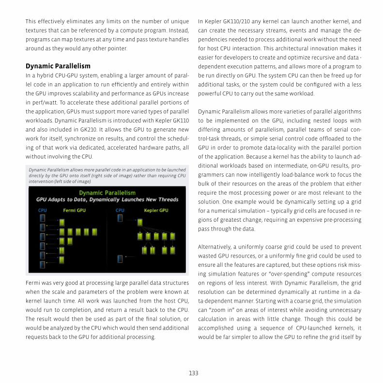
133
This effectively eliminates any limits on the number of unique
textures that can be referenced by a compute program. Instead,
programs can map textures at any time and pass texture handles
around as they would any other pointer.
Dynamic ParallelismIn a hybrid CPU-GPU system, enabling a larger amount of paral-
lel code in an application to run efficiently and entirely within
the GPU improves scalability and performance as GPUs increase
in perf/watt. To accelerate these additional parallel portions of
the application, GPUs must support more varied types of parallel
workloads. Dynamic Parallelism is introduced with Kepler GK110
and also included in GK210. It allows the GPU to generate new
work for itself, synchronize on results, and control the schedul-
ing of that work via dedicated, accelerated hardware paths, all
without involving the CPU.
Fermi was very good at processing large parallel data structures
when the scale and parameters of the problem were known at
kernel launch time. All work was launched from the host CPU,
would run to completion, and return a result back to the CPU.
The result would then be used as part of the final solution, or
would be analyzed by the CPU which would then send additional
requests back to the GPU for additional processing.
In Kepler GK110/210 any kernel can launch another kernel, and
can create the necessary streams, events and manage the de-
pendencies needed to process additional work without the need
for host CPU interaction. This architectural innovation makes it
easier for developers to create and optimize recursive and data -
dependent execution patterns, and allows more of a program to
be run directly on GPU. The system CPU can then be freed up for
additional tasks, or the system could be configured with a less
powerful CPU to carry out the same workload.
Dynamic Parallelism allows more varieties of parallel algorithms
to be implemented on the GPU, including nested loops with
differing amounts of parallelism, parallel teams of serial con-
trol-task threads, or simple serial control code offloaded to the
GPU in order to promote data-locality with the parallel portion
of the application. Because a kernel has the ability to launch ad-
ditional workloads based on intermediate, on-GPU results, pro-
grammers can now intelligently load-balance work to focus the
bulk of their resources on the areas of the problem that either
require the most processing power or are most relevant to the
solution. One example would be dynamically setting up a grid
for a numerical simulation – typically grid cells are focused in re-
gions of greatest change, requiring an expensive pre-processing
pass through the data.
Alternatively, a uniformly coarse grid could be used to prevent
wasted GPU resources, or a uniformly fine grid could be used to
ensure all the features are captured, but these options risk miss-
ing simulation features or “over-spending” compute resources
on regions of less interest. With Dynamic Parallelism, the grid
resolution can be determined dynamically at runtime in a da-
ta-dependent manner. Starting with a coarse grid, the simulation
can “zoom in” on areas of interest while avoiding unnecessary
calculation in areas with little change. Though this could be
accomplished using a sequence of CPU-launched kernels, it
would be far simpler to allow the GPU to refine the grid itself by
Dynamic Parallelism allows more parallel code in an application to be launched directly by the GPU onto itself (right side of image) rather than requiring CPU intervention (left side of image).
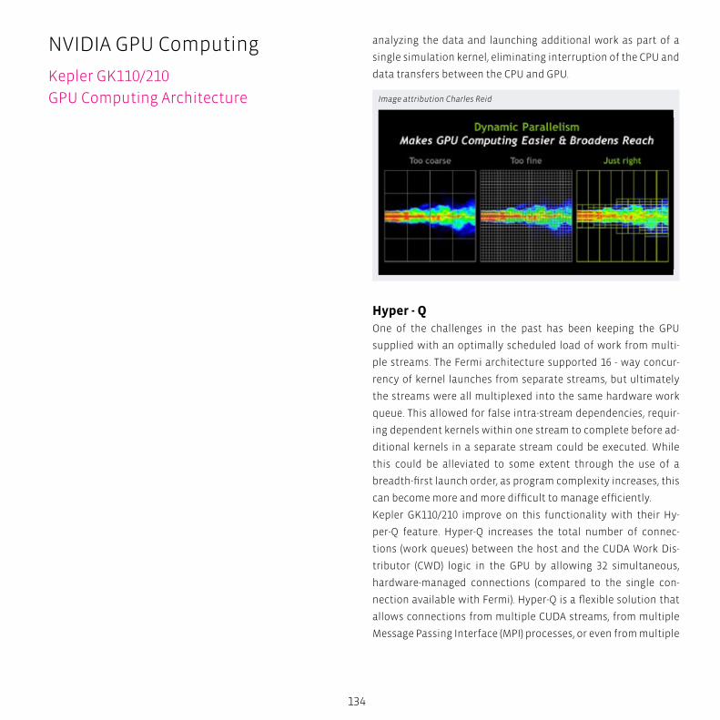
134
analyzing the data and launching additional work as part of a
single simulation kernel, eliminating interruption of the CPU and
data transfers between the CPU and GPU.
Hyper - QOne of the challenges in the past has been keeping the GPU
supplied with an optimally scheduled load of work from multi-
ple streams. The Fermi architecture supported 16 - way concur-
rency of kernel launches from separate streams, but ultimately
the streams were all multiplexed into the same hardware work
queue. This allowed for false intra-stream dependencies, requir-
ing dependent kernels within one stream to complete before ad-
ditional kernels in a separate stream could be executed. While
this could be alleviated to some extent through the use of a
breadth-first launch order, as program complexity increases, this
can become more and more difficult to manage efficiently.
Kepler GK110/210 improve on this functionality with their Hy-
per-Q feature. Hyper-Q increases the total number of connec-
tions (work queues) between the host and the CUDA Work Dis-
tributor (CWD) logic in the GPU by allowing 32 simultaneous,
hardware-managed connections (compared to the single con-
nection available with Fermi). Hyper-Q is a flexible solution that
allows connections from multiple CUDA streams, from multiple
Message Passing Interface (MPI) processes, or even from multiple
Image attribution Charles Reid
NVIDIA GPU Computing
Kepler GK110/210
GPU Computing Architecture
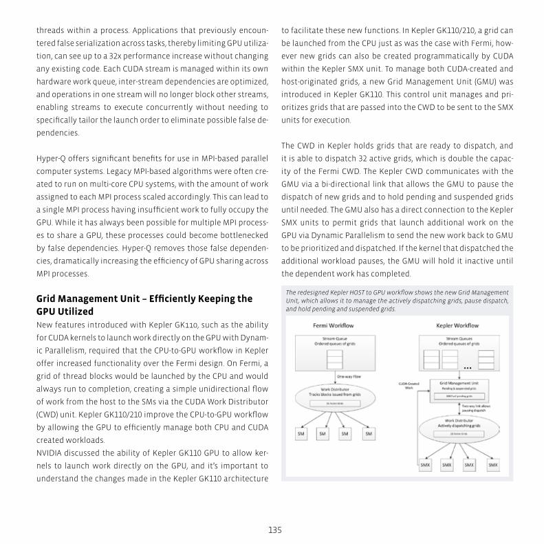
135
threads within a process. Applications that previously encoun-
tered false serialization across tasks, thereby limiting GPU utiliza-
tion, can see up to a 32x performance increase without changing
any existing code. Each CUDA stream is managed within its own
hardware work queue, inter-stream dependencies are optimized,
and operations in one stream will no longer block other streams,
enabling streams to execute concurrently without needing to
specifically tailor the launch order to eliminate possible false de-
pendencies.
Hyper-Q offers significant benefits for use in MPI-based parallel
computer systems. Legacy MPI-based algorithms were often cre-
ated to run on multi-core CPU systems, with the amount of work
assigned to each MPI process scaled accordingly. This can lead to
a single MPI process having insufficient work to fully occupy the
GPU. While it has always been possible for multiple MPI process-
es to share a GPU, these processes could become bottlenecked
by false dependencies. Hyper-Q removes those false dependen-
cies, dramatically increasing the efficiency of GPU sharing across
MPI processes.
Grid Management Unit – Efficiently Keeping the GPU Utilized New features introduced with Kepler GK110, such as the ability
for CUDA kernels to launch work directly on the GPU with Dynam-
ic Parallelism, required that the CPU-to-GPU workflow in Kepler
offer increased functionality over the Fermi design. On Fermi, a
grid of thread blocks would be launched by the CPU and would
always run to completion, creating a simple unidirectional flow
of work from the host to the SMs via the CUDA Work Distributor
(CWD) unit. Kepler GK110/210 improve the CPU-to-GPU workflow
by allowing the GPU to efficiently manage both CPU and CUDA
created workloads.
NVIDIA discussed the ability of Kepler GK110 GPU to allow ker-
nels to launch work directly on the GPU, and it’s important to
understand the changes made in the Kepler GK110 architecture
to facilitate these new functions. In Kepler GK110/210, a grid can
be launched from the CPU just as was the case with Fermi, how-
ever new grids can also be created programmatically by CUDA
within the Kepler SMX unit. To manage both CUDA-created and
host-originated grids, a new Grid Management Unit (GMU) was
introduced in Kepler GK110. This control unit manages and pri-
oritizes grids that are passed into the CWD to be sent to the SMX
units for execution.
The CWD in Kepler holds grids that are ready to dispatch, and
it is able to dispatch 32 active grids, which is double the capac-
ity of the Fermi CWD. The Kepler CWD communicates with the
GMU via a bi-directional link that allows the GMU to pause the
dispatch of new grids and to hold pending and suspended grids
until needed. The GMU also has a direct connection to the Kepler
SMX units to permit grids that launch additional work on the
GPU via Dynamic Parallelism to send the new work back to GMU
to be prioritized and dispatched. If the kernel that dispatched the
additional workload pauses, the GMU will hold it inactive until
the dependent work has completed.
The redesigned Kepler HOST to GPU workflow shows the new Grid Management Unit, which allows it to manage the actively dispatching grids, pause dispatch, and hold pending and suspended grids.
BOX
136
transtec has strived for developing well-engineered GPU Com-
puting solutions from the very beginning of the Tesla era. From
High-Performance GPU Workstations to rack-mounted Tesla
server solutions, transtec has a broad range of specially de-
signed systems available.
As an NVIDIA Tesla Preferred Provider (TPP), transtec is able to
provide customers with the latest NVIDIA GPU technology as
well as fully-engineered hybrid systems and Tesla Preconfig-
ured Clusters. Thus, customers can be assured that transtec’s
large experience in HPC cluster solutions is seamlessly brought
into the GPU computing world. Performance Engineering made
by transtec.
NVIDIA GPU Computing
Kepler GK110/210
GPU Computing Architecture

137
NVIDIA GPUDirectWhen working with a large amount of data, increasing the data
throughput and reducing latency is vital to increasing compute
performance. Kepler GK110/210 support the RDMA feature in
NVIDIA GPUDirect, which is designed to improve performance
by allowing direct access to GPU memory by third-party devices
such as IB adapters, NICs, and SSDs.
When using CUDA 5.0 or later, GPUDirect provides the following
important features:
� Direct memory access (DMA) between NIC and GPU without
the need for CPU-side data buffering.
� Significantly improved MPISend/MPIRecv efficiency between
GPU and other nodes in a network.
� Eliminates CPU bandwidth and latency bottlenecks
�Works with variety of 3rd-party network, capture and storage
devices
Applications like reverse time migration (used in seismic imaging
for oil & gas exploration) distribute the large imaging data across
several GPUs. Hundreds of GPUs must collaborate to crunch the
data, often communicating intermediate results. GPUDirect en-
ables much higher aggregate bandwidth for this GPU-to-GPU
GPUDirect RDMA allows direct access to GPU memory from 3rd-party devices such as network adapters, which translates into direct transfers between GPUs across nodes as well.
communication scenario within a server and across servers with
the P2P and RDMA features. Kepler GK110 also supports other
GPUDirect features such as Peer-to-Peer and GPUDirect for Video.
Kepler Memory Subsystem – L1, L2, ECC Kepler’s memory hierarchy is organized similarly to Fermi. The
Kepler architecture supports a unified memory request path for
loads and stores, with an L1 cache per SMX multiprocessor. Ke-
pler GK110 also enables compiler-directed use of an additional
new cache for read-only data, as described below.
Configurable shared memory and L1 CacheIn the Kepler GK110 architecture, as in the previous generation
Fermi architecture, each SMX has 64 KB of on-chip memory that
can be configured as 48 KB of Shared memory with 16 KB of L1
cache, or as 16 KB of shared memory with 48 KB of L1 cache.
Kepler now allows for additional flexibility in configuring the
allocation of shared memory and L1 cache by permitting a 32 KB/
32 KB split between shared memory and L1 cache.
Configurable Shared Memory and L1 Cache
138
To support the increased throughput of each SMX unit, the
shared memory bandwidth for 64 bit and larger load operations
is also doubled compared to the Fermi SM, to 256 byte per core
clock. For the GK210 architecture, the total amount of configu-
rable memory is doubled to 128 KB, allowing a maximum of 112
KB shared memory and 16 KB of L1 cache. Other possible memory
configurations are 32 KB L1 cache with 96 KB shared memory, or
48 KB L1 cache with 80 KB of shared memory.
This increase allows a similar improvement in concurrency of
threads as is enabled by the register file capacity improvement
described above.
48 KB Read-Only Data CacheIn addition to the L1 cache, Kepler introduces a 48 KB cache for
data that is known to be read-only for the duration of the func-
tion. In the Fermi generation, this cache was accessible only by
the Texture unit. Expert programmers often found it advanta-
geous to load data through this path explicitly by mapping their
data as textures, but this approach had many limitations.
In Kepler, in addition to significantly increasing the capacity of
this cache along with the texture horsepower increase, we de-
cided to make the cache directly accessible to the SM for general
load operations. Use of the read-only path is beneficial because
it takes both load and working set footprint off of the Shared/L1
cache path. In addition, the Read-Only Data Cache’s higher tag
bandwidth supports full speed unaligned memory access pat-
terns among other scenarios.
Use of the read-only path can be managed automatically by the
compiler or explicitly by the programmer. Access to any variable
or data structure that is known to be constant through program-
mer use of the C99 standard “const __restrict” keyword may be
tagged by the compiler to be loaded through the Read- Only Data
Cache. The programmer can also explicitly use this path with the
__ldg() intrinsic.
NVIDIA GPU Computing
Kepler GK110/210
GPU Computing Architecture
NVIDIA, GeForce, Tesla, CUDA, PhysX, GigaThread, NVIDIA Par-
allel Data Cache and certain other trademarks and logos ap-
pearing in this brochure, are trademarks or registered trade-
marks of NVIDIA orporation.
S
N
EW
SESW
NENW
tech BOX
139
Improved L2 CacheThe Kepler GK110/210 GPUs feature 1536 KB of dedicated L2
cache memory, double the amount of L2 available in the Fermi
architecture. The L2 cache is the primary point of data unifica-
tion between the SMX units, servicing all load, store, and texture
requests and providing efficient, high speed data sharing across
the GPU.
The L2 cache on Kepler offers up to 2x of the bandwidth per clock
available in Fermi. Algorithms for which data addresses are not
known beforehand, such as physics solvers, ray tracing, and
sparse matrix multiplication especially benefit from the cache
hierarchy. Filter and convolution kernels that require multiple
SMs to read the same data also benefit.
Memory Protection SupportLike Fermi, Kepler’s register files, shared memories, L1 cache, L2
cache and DRAM memory are protected by a Single-Error Correct
Double-Error Detect (SECDED) ECC code. In addition, the Read-
Only Data Cache supports single-error correction through a par-
ity check; in the event of a parity error, the cache unit automati-
cally invalidates the failed line, forcing a read of the correct data
from L2.
ECC checkbit fetches from DRAM necessarily consume some
amount of DRAM bandwidth, which results in a performance
difference between ECC-enabled and ECC-disabled operation,
especially on memory bandwidth-sensitive applications. Kepler
GK110 implements several optimizations to ECC checkbit fetch
handling based on Fermi experience. As a result, the ECC on-vs-
off performance delta has been reduced by an average of 66%,
as measured across our internal compute application test suite.
CUDACUDA is a combination hardware/software platform that
enables NVIDIA GPUs to execute programs written with C,
C++, Fortran, and other languages. A CUDA program invokes
parallel functions called kernels that execute across many
parallel threads. The programmer or compiler organizes
these threads into thread blocks and grids of thread blocks.
Each thread within a thread block executes an instance of
the kernel. Each thread also has thread and block IDs within
its thread block and grid, a program counter, registers, per-
thread private memory, inputs, and output results.
A thread block is a set of concurrently executing threads that
can cooperate among themselves through barrier synchro-
nization and shared memory. A thread block has a block ID
within its grid. A grid is an array of thread blocks that execute
the same kernel, read inputs from global memory, write re-
sults to global memory, and synchronize between dependent
kernel calls. In the CUDA parallel programming model, each
thread has a per-thread private memory space used for regis-
ter spills, function calls, and C automatic array variables. Each
thread block has a per-block shared memory space used for
inter-thread communication, data sharing, and result sharing
in parallel algorithms. Grids of thread blocks share results in
Global Memory space after kernel-wide global synchroniza-
tion.
CUDA Hardware ExecutionCUDA’s hierarchy of threads maps to a hierarchy of proces-
sors on the GPU; a GPU executes one or more kernel grids; a
streaming multiprocessor (SM on Fermi / SMX on Kepler) ex-
ecutes one or more thread blocks; and CUDA cores and other
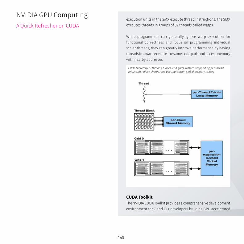
140
execution units in the SMX execute thread instructions. The SMX
executes threads in groups of 32 threads called warps.
While programmers can generally ignore warp execution for
functional correctness and focus on programming individual
scalar threads, they can greatly improve performance by having
threads in a warp execute the same code path and access memory
with nearby addresses.
CUDA Hierarchy of threads, blocks, and grids, with corresponding per-thread private, per-block shared,-and per-application global memory spaces.
NVIDIA GPU Computing
A Quick Refresher on CUDA
CUDA Toolkit The NVIDIA CUDA Toolkit provides a comprehensive development
environment for C and C++ developers building GPU-accelerated
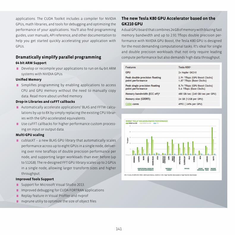
141
applications. The CUDA Toolkit includes a compiler for NVIDIA
GPUs, math libraries, and tools for debugging and optimizing the
performance of your applications. You’ll also find programming
guides, user manuals, API reference, and other documentation to
help you get started quickly accelerating your application with
GPUs.
Dramatically simplify parallel programming64 bit ARM Support
� Develop or recompile your applications to run on 64-bit ARM
systems with NVIDIA GPUs
Unified Memory
� Simplifies programming by enabling applications to access
CPU and GPU memory without the need to manually copy
data. Read more about unified memory.
Drop-in Libraries and cuFFT callbacks
� Automatically accelerate applications’ BLAS and FFTW calcu-
lations by up to 8X by simply replacing the existing CPU librar-
ies with the GPU-accelerated equivalents.
� Use cuFFT callbacks for higher performance custom process-
ing on input or output data.
Multi-GPU scaling
� cublasXT – a new BLAS GPU library that automatically scales
performance across up to eight GPUs in a single node, deliver-
ing over nine teraflops of double precision performance per
node, and supporting larger workloads than ever before (up
to 512GB). The re-designed FFT GPU library scales up to 2 GPUs
in a single node, allowing larger transform sizes and higher
throughput.
Improved Tools Support
� Support for Microsoft Visual Studio 2013.
� Improved debugging for CUDA FORTRAN applications
� Replay feature in Visual Profiler and nvprof
� nvprune utiliy to optimize the size of object files
The new Tesla K80 GPU Accelerator based on the GK210 GPUA dual GPU board that combines 24 GB of memory with blazing fast
memory bandwidth and up to 2.91 Tflops double precision per-
formance with NVIDIA GPU Boost, the Tesla K80 GPU is designed
for the most demanding computational tasks. It’s ideal for single
and double precision workloads that not only require leading
compute performance but also demands high data throughput.

Intel Xeon Phi Coprocessor – The ArchitectureIntel Many Integrated Core (Intel MIC) architecture combines many Intel CPU cores onto
a single chip. Intel MIC architecture is targeted for highly parallel, High Performance
Computing (HPC) workloads in a variety of fields such as computational physics, chem-
istry, biology, and financial services. Today such workloads are run as task parallel pro-
grams on large compute clusters.
Engi
nee
rin
g L
ife
Scie
nce
s A
uto
mo
tive
P
rice
Mo
del
lin
g A
ero
spac
e C
AE
Dat
a A
nal
ytic
s
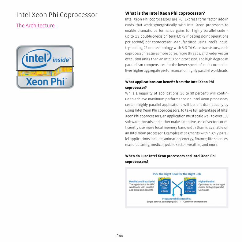
144
Intel Xeon Phi Coprocessor
The Architecture
What is the Intel Xeon Phi coprocessor?Intel Xeon Phi coprocessors are PCI Express form factor add-in
cards that work synergistically with Intel Xeon processors to
enable dramatic performance gains for highly parallel code –
up to 1.2 double-precision teraFLOPS (floating point operations
per second) per coprocessor. Manufactured using Intel’s indus-
try-leading 22 nm technology with 3-D Tri-Gate transistors, each
coprocessor features more cores, more threads, and wider vector
execution units than an Intel Xeon processor. The high degree of
parallelism compensates for the lower speed of each core to de-
liver higher aggregate performance for highly parallel workloads.
What applications can benefit from the Intel Xeon Phi
coprocessor?
While a majority of applications (80 to 90 percent) will contin-
ue to achieve maximum performance on Intel Xeon processors,
certain highly parallel applications will benefit dramatically by
using Intel Xeon Phi coprocessors. To take full advantage of Intel
Xeon Phi coprocessors, an application must scale well to over 100
software threads and either make extensive use of vectors or ef-
ficiently use more local memory bandwidth than is available on
an Intel Xeon processor. Examples of segments with highly paral-
lel applications include: animation, energy, finance, life sciences,
manufacturing, medical, public sector, weather, and more.
When do I use Intel Xeon processors and Intel Xeon Phi
coprocessors?

S
N
EW
SESW
NENW
tech BOX
145
Think “resuse” rather than “recode”
Since languages, tools, and applications are compatible for
both Intel Xeon processor and coprocessors, now you can think
“reuse” rather than “recode”.
Single programming model for all your code
The Intel Xeon Phi coprocessor gives developers a hardware de-
sign point optimized for extreme parallelism, without requiring
them to re-architect or rewrite their code. No need to rethink the
entire problem or learn a new programming model; simply rec-
ompile and optimize existing code using familiar tools, libraries,
and runtimes.
Performance multiplier
By maintaining a single source code between Intel Xeon proces-
sors and Intel Xeon Phi coprocessors, developers optimize once
for parallelism but maximize performance on both processor
and coprocessor.
Execution flexibility
Intel Xeon Phi is designed from the ground up for high-perfor-
mance computing. Unlike a GPU, a coprocessor can host an oper-
ating system, be fully IP addressable, and support standards such
as Message Passing Interface (MPI). Additionally, it can operate in
multiple execution modes:
� “Symmetric” mode: Workload tasks are shared between the
host processor and coprocessor
� “Native” mode: Workload resides entirely on the coprocessor,
and essentially acts as a separate compute nodes
� “Offload” mode: Workload resides on the host processor, and
parts of the workload are sent out to the coprocessor as needed
Multiple Intel Xeon Phi coprocessors can be installed in a sin-
gle host system. Within a single system, the coprocessors can
communicate with each other through the PCIe peer-to-peer
interconnect without any intervention from the host. Similarly,
A Family of Coprocessors for Diverse Needs Intel Xeon Phi coprocessors provide up to 61 cores, 244
threads, and 1.2 teraflops of performance, and they come
in a variety of configurations to address diverse hardware,
software, workload, performance, and efficiency require-
ments. They also come in a variety of form factors, including
a standard PCIe x16 form factor (with active, passive, or no
thermal solution), and a dense form factor that offers addi-
tional design flexibility.
� The Intel Xeon Phi Coprocessor 3100 family provides out-
standing parallel performance. It is an excellent choice for
compute-bound workloads, such as MonteCarlo, black-
Scholes, HPL, LifeSc, and many others. Active and passive
cooling options provide flexible support for a variety of
server and workstation systems.
� The Intel Xeon Phi Coprocessor 5100 family is opti-
mized for high-density computing and is well-suited for
workloads that are memory-bandwidth bound, such as
STREAM, memory-capacity bound, such as ray-tracing, or
both, such as reverse time migration (RTM). These copro-
cessors are passively cooled and have the lowest thermal
design power (TDP) of the Intel Xeon Phi product family.
� The Intel Xeon Phi Coprocessor 7100 family provides the
most features and the highest performance and memory
capacity of the Intel Xeon Phi product family. This family
supports Intel Turbo boost Technology 1.0, which increas-
es core frequencies during peak workloads when thermal
conditions allow. Passive and no thermal solution options
enable powerful and innovative computing solutions.
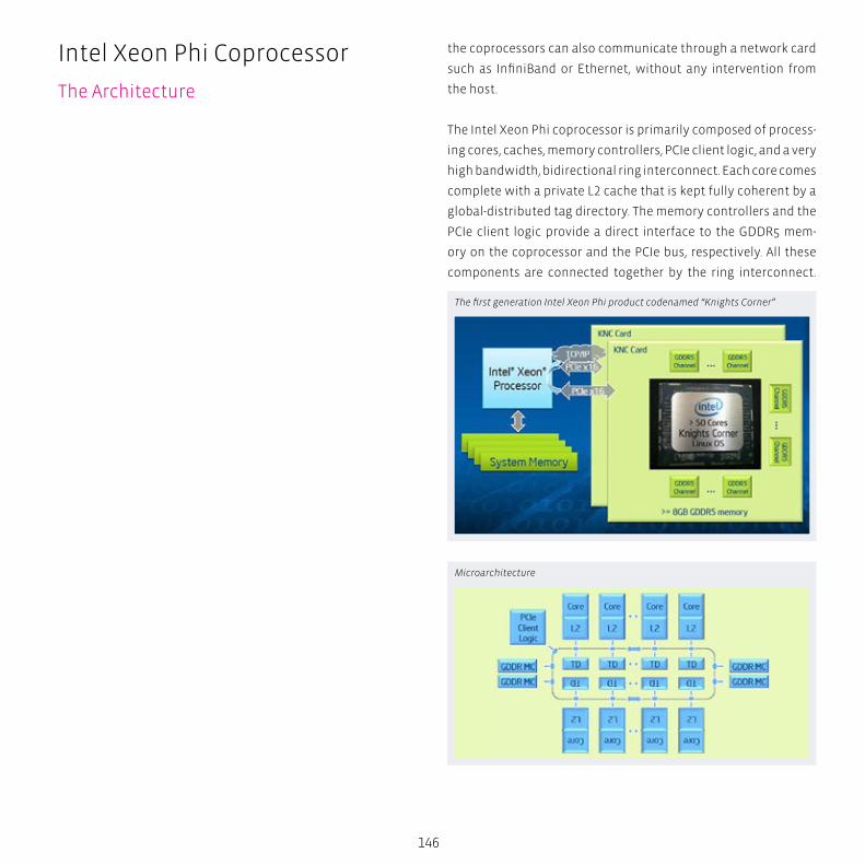
146
the coprocessors can also communicate through a network card
such as InfiniBand or Ethernet, without any intervention from
the host.
The Intel Xeon Phi coprocessor is primarily composed of process-
ing cores, caches, memory controllers, PCIe client logic, and a very
high bandwidth, bidirectional ring interconnect. Each core comes
complete with a private L2 cache that is kept fully coherent by a
global-distributed tag directory. The memory controllers and the
PCIe client logic provide a direct interface to the GDDR5 mem-
ory on the coprocessor and the PCIe bus, respectively. All these
components are connected together by the ring interconnect.
The first generation Intel Xeon Phi product codenamed “Knights Corner”
Microarchitecture
Intel Xeon Phi Coprocessor
The Architecture
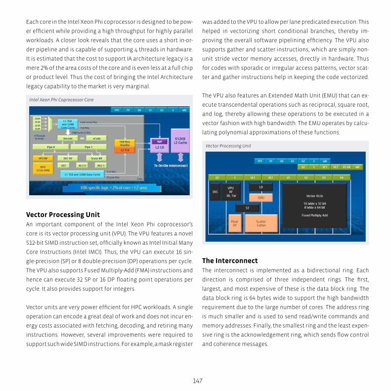
147
Each core in the Intel Xeon Phi coprocessor is designed to be pow-
er efficient while providing a high throughput for highly parallel
workloads. A closer look reveals that the core uses a short in-or-
der pipeline and is capable of supporting 4 threads in hardware.
It is estimated that the cost to support IA architecture legacy is a
mere 2% of the area costs of the core and is even less at a full chip
or product level. Thus the cost of bringing the Intel Architecture
legacy capability to the market is very marginal.
Vector Processing UnitAn important component of the Intel Xeon Phi coprocessor’s
core is its vector processing unit (VPU). The VPU features a novel
512-bit SIMD instruction set, officially known as Intel Initial Many
Core Instructions (Intel IMCI). Thus, the VPU can execute 16 sin-
gle-precision (SP) or 8 double-precision (DP) operations per cycle.
The VPU also supports Fused Multiply-Add (FMA) instructions and
hence can execute 32 SP or 16 DP floating point operations per
cycle. It also provides support for integers.
Vector units are very power efficient for HPC workloads. A single
operation can encode a great deal of work and does not incur en-
ergy costs associated with fetching, decoding, and retiring many
instructions. However, several improvements were required to
support such wide SIMD instructions. For example, a mask register
was added to the VPU to allow per lane predicated execution. This
helped in vectorizing short conditional branches, thereby im-
proving the overall software pipelining efficiency. The VPU also
supports gather and scatter instructions, which are simply non-
unit stride vector memory accesses, directly in hardware. Thus
for codes with sporadic or irregular access patterns, vector scat-
ter and gather instructions help in keeping the code vectorized.
The VPU also features an Extended Math Unit (EMU) that can ex-
ecute transcendental operations such as reciprocal, square root,
and log, thereby allowing these operations to be executed in a
vector fashion with high bandwidth. The EMU operates by calcu-
lating polynomial approximations of these functions.
The InterconnectThe interconnect is implemented as a bidirectional ring. Each
direction is comprised of three independent rings. The first,
largest, and most expensive of these is the data block ring. The
data block ring is 64 bytes wide to support the high bandwidth
requirement due to the large number of cores. The address ring
is much smaller and is used to send read/write commands and
memory addresses. Finally, the smallest ring and the least expen-
sive ring is the acknowledgement ring, which sends flow control
and coherence messages.
Intel Xeon Phi Coprocessor Core
Vector Processing Unit
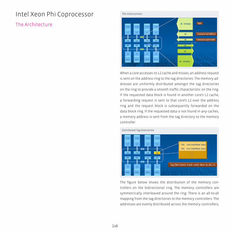
148
When a core accesses its L2 cache and misses, an address request
is sent on the address ring to the tag directories. The memory ad-
dresses are uniformly distributed amongst the tag directories
on the ring to provide a smooth traffic characteristic on the ring.
If the requested data block is found in another core’s L2 cache,
a forwarding request is sent to that core’s L2 over the address
ring and the request block is subsequently forwarded on the
data block ring. If the requested data is not found in any caches,
a memory address is sent from the tag directory to the memory
controller.
The figure below shows the distribution of the memory con-
trollers on the bidirectional ring. The memory controllers are
symmetrically interleaved around the ring. There is an all-to-all
mapping from the tag directories to the memory controllers. The
addresses are evenly distributed across the memory controllers,
The Interconnect
Distributed Tag Directories
Intel Xeon Phi Coprocessor
The Architecture

149
thereby eliminating hotspots and providing a uniform access
pattern which is essential for a good bandwidth response.
During a memory access, whenever an L2 cache miss occurs on a
core, the core generates an address request on the address ring
and queries the tag directories. If the data is not found in the tag
directories, the core generates another address request and que-
ries the memory for the data. Once the memory controller fetch-
es the data block from memory, it is returned back to the core
over the data ring. Thus during this process, one data block, two
address requests (and by protocol, two acknowledgement mes-
sages) are transmitted over the rings. Since the data block rings
are the most expensive and are designed to support the required
data bandwidth, it is necessary to increase the number of less ex-
pensive address and acknowledgement rings by a factor of two
to match the increased bandwidth requirement caused by the
higher number of requests on these rings.
Other Design FeaturesOther micro-architectural optimizations incorporated into the
Intel Xeon Phi coprocessor include a 64-entry second-level Trans-
lation Lookaside Buffer (TLB), simultaneous data cache loads and
stores, and 512KB L2 caches. Lastly, the Intel Xeon Phi coproc-
essor implements a 16 stream hardware prefetcher to improve
the cache hits and provide higher bandwidth. The figure below
shows the net performance improvements for the SPECfp 2006
benchmark suite for a single core, single thread runs. The results
indicate an average improvement of over 80% per cycle not in-
cluding frequency.
Per-Core ST Performance Improvement (per cycle)
Interleaved Memory Access
Interconnect: 2x AD/AK
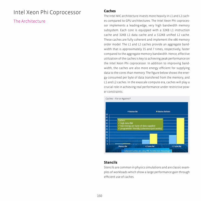
150
CachesThe Intel MIC architecture invests more heavily in L1 and L2 cach-
es compared to GPU architectures. The Intel Xeon Phi coproces-
sor implements a leading-edge, very high bandwidth memory
subsystem. Each core is equipped with a 32KB L1 instruction
cache and 32KB L1 data cache and a 512KB unified L2 cache.
These caches are fully coherent and implement the x86 memory
order model. The L1 and L2 caches provide an aggregate band-
width that is approximately 15 and 7 times, respectively, faster
compared to the aggregate memory bandwidth. Hence, effective
utilization of the caches is key to achieving peak performance on
the Intel Xeon Phi coprocessor. In addition to improving band-
width, the caches are also more energy efficient for supplying
data to the cores than memory. The figure below shows the ener-
gy consumed per byte of data transfered from the memory, and
L1 and L2 caches. In the exascale compute era, caches will play a
crucial role in achieving real performance under restrictive pow-
er constraints.
StencilsStencils are common in physics simulations and are classic exam-
ples of workloads which show a large performance gain through
efficient use of caches.
Caches – For or Against?
Intel Xeon Phi Coprocessor
The Architecture
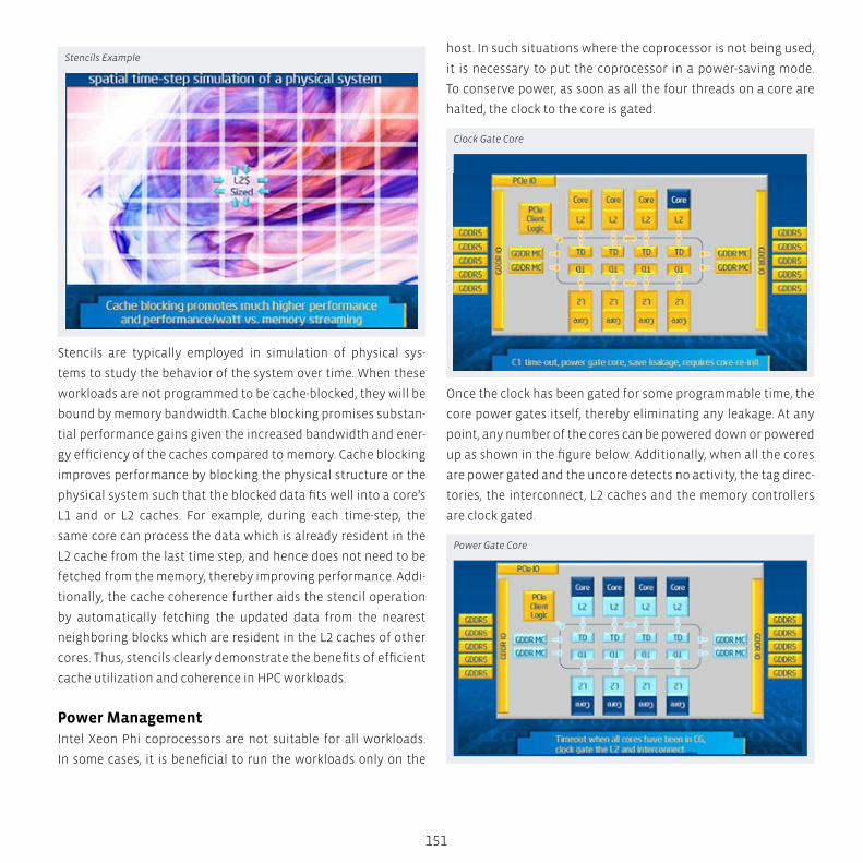
151
Stencils are typically employed in simulation of physical sys-
tems to study the behavior of the system over time. When these
workloads are not programmed to be cache-blocked, they will be
bound by memory bandwidth. Cache blocking promises substan-
tial performance gains given the increased bandwidth and ener-
gy efficiency of the caches compared to memory. Cache blocking
improves performance by blocking the physical structure or the
physical system such that the blocked data fits well into a core’s
L1 and or L2 caches. For example, during each time-step, the
same core can process the data which is already resident in the
L2 cache from the last time step, and hence does not need to be
fetched from the memory, thereby improving performance. Addi-
tionally, the cache coherence further aids the stencil operation
by automatically fetching the updated data from the nearest
neighboring blocks which are resident in the L2 caches of other
cores. Thus, stencils clearly demonstrate the benefits of efficient
cache utilization and coherence in HPC workloads.
Power ManagementIntel Xeon Phi coprocessors are not suitable for all workloads.
In some cases, it is beneficial to run the workloads only on the
host. In such situations where the coprocessor is not being used,
it is necessary to put the coprocessor in a power-saving mode.
To conserve power, as soon as all the four threads on a core are
halted, the clock to the core is gated.
Once the clock has been gated for some programmable time, the
core power gates itself, thereby eliminating any leakage. At any
point, any number of the cores can be powered down or powered
up as shown in the figure below. Additionally, when all the cores
are power gated and the uncore detects no activity, the tag direc-
tories, the interconnect, L2 caches and the memory controllers
are clock gated.
Clock Gate Core
Power Gate Core
Stencils Example
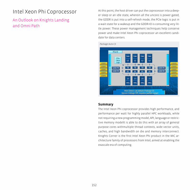
152
At this point, the host driver can put the coprocessor into a deep-
er sleep or an idle state, wherein all the uncore is power gated,
the GDDR is put into a self-refresh mode, the PCIe logic is put in
a wait state for a wakeup and the GDDR-IO is consuming very lit-
tle power. These power management techniques help conserve
power and make Intel Xeon Phi coprocessor an excellent candi-
date for data centers.
SummaryThe Intel Xeon Phi coprocessor provides high performance, and
performance per watt for highly parallel HPC workloads, while
not requiring a new programming model, API, language or restric-
tive memory modelIt is able to do this with an array of general
purpose cores withmultiple thread contexts, wide vector units,
caches, and high bandwidth on die and memory interconnect.
Knights Corner is the first Intel Xeon Phi product in the MIC ar-
chitecture family of processors from Intel, aimed at enabling the
exascale era of computing.
Package Auto C3
Intel Xeon Phi Coprocessor
An Outlook on Knights Landing
and Omni Path
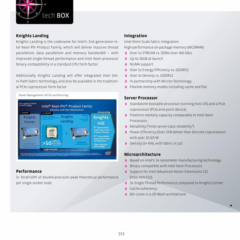
S
N
EW
SESW
NENW
tech BOX
153
Knights Landing Knights Landing is the codename for Intel’s 2nd generation In-
tel Xeon Phi Product Family, which will deliver massive thread
parallelism, data parallelism and memory bandwidth – with
improved single-thread performance and Intel Xeon processor
binary-compatibility in a standard CPU form factor.
Additionally, Knights Landing will offer integrated Intel Om-
ni-Path fabric technology, and also be available in the tradition-
al PCIe coprocessor form factor.
Performance3+ TeraFLOPS of double-precision peak theoretical performance
per single socket node.
Power Management: All On and Running
IntegrationIntel Omni Scale fabric integration
High-performance on-package memory (MCDRAM)
� Over 5x STREAM vs. DDR4 Over 400 GB/s
� Up to 16GB at launch
� NUMA support
� Over 5x Energy Efficiency vs. GDDR52
� Over 3x Density vs. GDDR52
� In partnership with Micron Technology
� Flexible memory modes including cache and flat
Server Processor � Standalone bootable processor (running host OS) and a PCIe
coprocessor (PCIe end-point device)
� Platform memory capacity comparable to Intel Xeon
Processors
� Reliability (“Intel server-class reliability”)
� Power Efficiency (Over 25% better than discrete coprocessor)
with over 10 GF/W
� Density (3+ KNL with fabric in 1U)
Microarchitecture � Based on Intel’s 14 nanometer manufacturing technology
� Binary compatible with Intel Xeon Processors
� Support for Intel Advanced Vector Extensions 512
(Intel AVX-512)
� 3x Single-Thread Performance compared to Knights Corner
� Cache-coherency
� 60+ cores in a 2D Mesh architecture
154
4 Threads / Core
� Deep Out-of-Order Buffers
� Gather/scatter in hardware
� Advanced Branch Prediction
� High cache bandwidth
� Most of today’s parallel optimizations carry forward to KNL
� Multiple NUMA domain support per socket
Roadmap � Knights Hill is the codename for the 3rd generation of the
Intel Xeon Phi product family
� Based on Intel’s 10 nanometer manufacturing technology
� Integrated 2nd generation Intel Omni-Path Fabric
Omni Path - the Next-Generation FabricIntel Omni-Path Architecture is designed to deliver the perfor-
mance for tomorrow’s high performance computing (HPC) work-
loads and the ability to scale to tens – and eventually hundreds
– of thousands of nodes at a cost-competitive price to today’s
fabrics.
This next-generation fabric from Intel builds on the Intel True
Scale Fabric with an end-to-end solution, including PCIe adapters,
silicon, switches, cables, and management software. Customers
deploying Intel True Scale Fabric today will be able to migrate to
Intel Omni-Path Architecture through an Intel upgrade program.
In the near future, Intel will integrate the Intel Omni-Path Host
Fabric Interface onto future generations of Intel Xeon processors
and Intel Xeon Phi processors to address several key challenges
of HPC computing centers:
Intel Xeon Phi Coprocessor
An Outlook on Knights Landing
and Omni Path
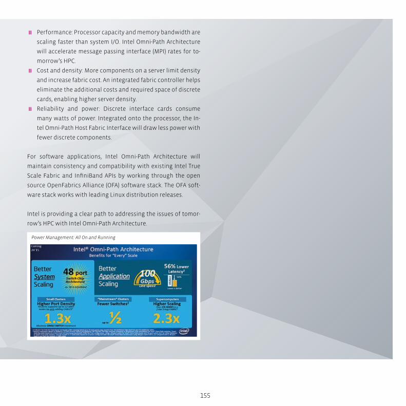
155
� Performance: Processor capacity and memory bandwidth are
scaling faster than system I/O. Intel Omni-Path Architecture
will accelerate message passing interface (MPI) rates for to-
morrow’s HPC.
� Cost and density: More components on a server limit density
and increase fabric cost. An integrated fabric controller helps
eliminate the additional costs and required space of discrete
cards, enabling higher server density.
� Reliability and power: Discrete interface cards consume
many watts of power. Integrated onto the processor, the In-
tel Omni-Path Host Fabric Interface will draw less power with
fewer discrete components.
For software applications, Intel Omni-Path Architecture will
maintain consistency and compatibility with existing Intel True
Scale Fabric and InfiniBand APIs by working through the open
source OpenFabrics Alliance (OFA) software stack. The OFA soft-
ware stack works with leading Linux distribution releases.
Intel is providing a clear path to addressing the issues of tomor-
row’s HPC with Intel Omni-Path Architecture.
Power Management: All On and Running

InfiniBand High-Speed InterconnectInfiniBand (IB) is an efficient I/O technology that provides high-speed data transfers
and ultra-low latencies for computing and storage over a highly reliable and scalable
single fabric. The InfiniBand industry standard ecosystem creates cost effective hard-
ware and software solutions that easily scale from generation to generation.
InfiniBand is a high-bandwidth, low-latency network interconnect solution that has
grown tremendous market share in the High Performance Computing (HPC) cluster
community. InfiniBand was designed to take the place of today’s data center network-
ing technology. In the late 1990s, a group of next generation I/O architects formed an
open, community driven network technology to provide scalability and stability based
on successes from other network designs.
Today, InfiniBand is a popular and widely used I/O fabric among customers within the
Top500 supercomputers: major Universities and Labs; Life Sciences; Biomedical; Oil and
Gas (Seismic, Reservoir, Modeling Applications); Computer Aided Design and Engineer-
ing; Enterprise Oracle; and Financial Applications.
Life
Sci
en
ces
Ris
k A
na
lysi
s S
imu
lati
on
B
ig D
ata
An
aly
tics
H
igh
Pe
rfo
rma
nce
Co
mp
uti
ng
158
InfiniBand was designed to meet the evolving needs of the
high performance computing market. Computational science
depends on InfiniBand to deliver:
� High Bandwidth: Supports host connectivity of 10Gbps with
Single Data Rate (SDR), 20Gbps with Double Data Rate (DDR),
and 40Gbps with Quad Data Rate (QDR), all while offering an
80Gbps switch for link switching
� Low Latency: Accelerates the performance of HPC and enter-
prise computing applications by providing ultra-low latencies
� Superior Cluster Scaling: Point-to-point latency remains low
as node and core counts scale – 1.2 µs. Highest real message
per adapter: each PCIe x16 adapter drives 26 million messag-
es per second. Excellent communications/computation over-
lap among nodes in a cluster
� High Efficiency: InfiniBand allows reliable protocols like Re-
mote Direct Memory Access (RDMA) communication to occur
between interconnected hosts, thereby increasing efficiency
� Fabric Consolidation and Energy Savings: InfiniBand can
consolidate networking, clustering, and storage data over a
single fabric, which significantly lowers overall power, real
estate, and management overhead in data centers. Enhanced
Quality of Service (QoS) capabilities support running and
managing multiple workloads and traffic classes
� Data Integrity and Reliability: InfiniBand provides the high-
est levels of data integrity by performing Cyclic Redundancy
Checks (CRCs) at each fabric hop and end-to-end across the
fabric to avoid data corruption. To meet the needs of mission
critical applications and high levels of availability, InfiniBand
provides fully redundant and lossless I/O fabrics with auto-
matic failover path and link layer multi-paths
InfiniBand
The Architecture
Intel is a global leader and technology innovator in high performance net-working, including adapters, switches and ASICs.
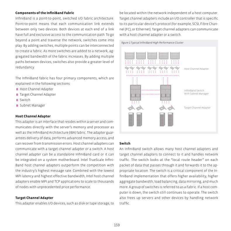
Host Channel Adapter
InfiniBand SwitchWith Subnet Manager
Target Channel Adapter
159
Components of the InfiniBand Fabric
InfiniBand is a point-to-point, switched I/O fabric architecture.
Point-to-point means that each communication link extends
between only two devices. Both devices at each end of a link
have full and exclusive access to the communication path. To go
beyond a point and traverse the network, switches come into
play. By adding switches, multiple points can be interconnected
to create a fabric. As more switches are added to a network, ag-
gregated bandwidth of the fabric increases. By adding multiple
paths between devices, switches also provide a greater level of
redundancy.
The InfiniBand fabric has four primary components, which are
explained in the following sections:
� Host Channel Adapter
� Target Channel Adapter
� Switch
� Subnet Manager
Host Channel Adapter
This adapter is an interface that resides within a server and com-
municates directly with the server’s memory and processor as
well as the InfiniBand Architecture (IBA) fabric. The adapter guar-
antees delivery of data, performs advanced memory access, and
can recover from transmission errors. Host channel adapters can
communicate with a target channel adapter or a switch. A host
channel adapter can be a standalone InfiniBand card or it can
be integrated on a system motherboard. Intel TrueScale Infini-
Band host channel adapters outperform the competition with
the industry’s highest message rate. Combined with the lowest
MPI latency and highest effective bandwidth, Intel host channel
adapters enable MPI and TCP applications to scale to thousands
of nodes with unprecedented price performance.
Target Channel Adapter
This adapter enables I/O devices, such as disk or tape storage, to
be located within the network independent of a host computer.
Target channel adapters include an I/O controller that is specific
to its particular device’s protocol (for example, SCSI, Fibre Chan-
nel (FC), or Ethernet). Target channel adapters can communicate
with a host channel adapter or a switch.
Switch
An InfiniBand switch allows many host channel adapters and
target channel adapters to connect to it and handles network
traffic. The switch looks at the “local route header” on each
packet of data that passes through it and forwards it to the ap-
propriate location. The switch is a critical component of the In-
finiBand implementation that offers higher availability, higher
aggregate bandwidth, load balancing, data mirroring, and much
more. A group of switches is referred to as a Fabric. If a host com-
puter is down, the switch still continues to operate. The switch
also frees up servers and other devices by handling network
traffic.
figure 1 Typical InfiniBand High Performance Cluster
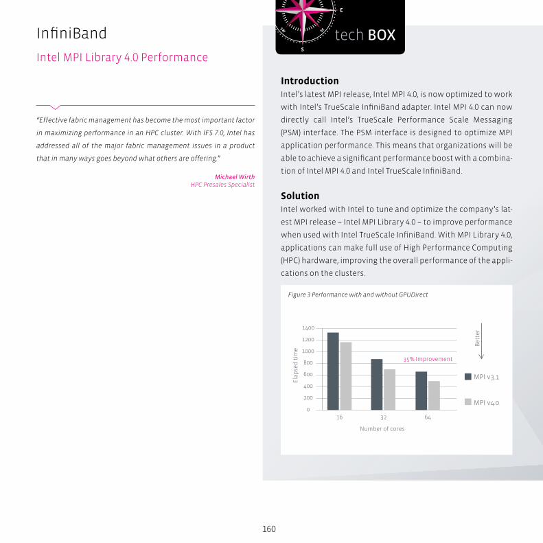
S
N
EW
SESW
NENW
tech BOX
MPI v3.1
MPI v4.0
1400
35% Improvement
1200
1000
800
600
400
200
0
Bet
ter
Ela
pse
d t
ime
Number of cores
16 32 64
160
InfiniBand
Intel MPI Library 4.0 Performance
IntroductionIntel’s latest MPI release, Intel MPI 4.0, is now optimized to work
with Intel’s TrueScale InfiniBand adapter. Intel MPI 4.0 can now
directly call Intel’s TrueScale Performance Scale Messaging
(PSM) interface. The PSM interface is designed to optimize MPI
application performance. This means that organizations will be
able to achieve a significant performance boost with a combina-
tion of Intel MPI 4.0 and Intel TrueScale InfiniBand.
SolutionIntel worked with Intel to tune and optimize the company’s lat-
est MPI release – Intel MPI Library 4.0 – to improve performance
when used with Intel TrueScale InfiniBand. With MPI Library 4.0,
applications can make full use of High Performance Computing
(HPC) hardware, improving the overall performance of the appli-
cations on the clusters.
Figure 3 Performance with and without GPUDirect
“Effective fabric management has become the most important factor
in maximizing performance in an HPC cluster. With IFS 7.0, Intel has
addressed all of the major fabric management issues in a product
that in many ways goes beyond what others are offering.”
Michael WirthHPC Presales Specialist
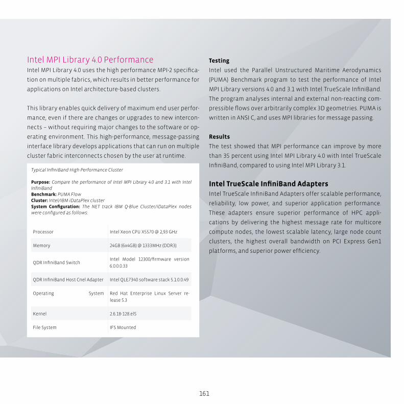
161
Intel MPI Library 4.0 PerformanceIntel MPI Library 4.0 uses the high performance MPI-2 specifica-
tion on multiple fabrics, which results in better performance for
applications on Intel architecture-based clusters.
This library enables quick delivery of maximum end user perfor-
mance, even if there are changes or upgrades to new intercon-
nects – without requiring major changes to the software or op-
erating environment. This high-performance, message-passing
interface library develops applications that can run on multiple
cluster fabric interconnects chosen by the user at runtime.
Testing
Intel used the Parallel Unstructured Maritime Aerodynamics
(PUMA) Benchmark program to test the performance of Intel
MPI Library versions 4.0 and 3.1 with Intel TrueScale InfiniBand.
The program analyses internal and external non-reacting com-
pressible flows over arbitrarily complex 3D geometries. PUMA is
written in ANSI C, and uses MPI libraries for message passing.
Results
The test showed that MPI performance can improve by more
than 35 percent using Intel MPI Library 4.0 with Intel TrueScale
InfiniBand, compared to using Intel MPI Library 3.1.
Intel TrueScale InfiniBand Adapters Intel TrueScale InfiniBand Adapters offer scalable performance,
reliability, low power, and superior application performance.
These adapters ensure superior performance of HPC appli-
cations by delivering the highest message rate for multicore
compute nodes, the lowest scalable latency, large node count
clusters, the highest overall bandwidth on PCI Express Gen1
platforms, and superior power efficiency.
Typical InfiniBand High Performance Cluster
Purpose: Compare the performance of Intel MPI Library 4.0 and 3.1 with Intel InfiniBandBenchmark: PUMA FlowCluster: Intel/IBM iDataPlex clusterSystem Configuration: The NET track IBM Q-Blue Cluster/iDataPlex nodes were configured as follows:
Processor Intel Xeon CPU X5570 @ 2,93 GHz
Memory 24GB (6x4GB) @ 1333MHz (DDR3)
QDR InfiniBand SwitchIntel Model 12300/firmware version
6.0.0.0.33
QDR InfiniBand Host Cnel Adapter Intel QLE7340 software stack 5.1.0.0.49
Operating System Red Hat Enterprise Linux Server re-
lease 5.3
Kernel 2.6.18-128.el5
File System IFS Mounted
162
The Intel TrueScale 12000 family of Multi-Protocol Fab-
ric Directors is the most highly integrated cluster com-
puting interconnect solution available. An ideal solu-
tion HPC, database clustering, and grid utility computing
applications, the 12000 Fabric Directors maximize cluster
and grid computing interconnect performance while sim-
plifying and reducing the cost of operating a data center.
Subnet Manager
The subnet manager is an application responsible for config-
uring the local subnet and ensuring its continued operation.
Configuration responsibilities include managing switch setup
and reconfiguring the subnet if a link goes down or a new one
is added.
How High Performance Computing Helps VerticalApplicationsEnterprises that want to do high performance computing must
balance the following scalability metrics as the core size and
the number of cores per node increase:
� Latency and Message Rate Scalability: must allow near line-
ar growth in productivity as the number of compute cores is
scaled.
� Power and Cooling Efficiency: as the cluster is scaled, power
and cooling requirements must not become major concerns
in today’s world of energy shortages and high-cost energy.
InfiniBand offers the promise of low latency, high bandwidth,
and unmatched scalability demanded by high performance
computing applications. IB adapters and switches that per-
form well on these key metrics allow enterprises to meet their
high-performance and MPI needs with optimal efficiency. The
IB solution allows enterprises to quickly achieve their compute
and business goals.
InfiniBand
The Architecture
BOX
163
transtec HPC solutions excel through their easy management
and high usability, while maintaining high performance and
quality throughout the whole lifetime of the system. As clusters
scale, issues like congestion mitigation and Quality-of-Service
can make a big difference in whether the fabric performs up to
its full potential.
With the intelligent choice of Intel InfiniBand products, trans-
tec remains true to combining the best components together
to provide the full best-of-breed solution stack to the customer.
transtec HPC engineering experts are always available to fine-
tune customers’ HPC cluster systems and InfiniBand fabrics to
get the maximum performance while at the same time provide
them with an easy-to-manage and easy-to-use HPC solution.
S
N
EW
SESW
NENW
tech BOX
164
InfiniBand
Intel Fabric Suite 7
Intel Fabric Suite 7Maximizing Investments in High Performance Computing
Around the world and across all industries, high performance
computing (HPC) is used to solve today’s most demanding com-
puting problems. As today’s high performance computing chal-
lenges grow in complexity and importance, it is vital that the
software tools used to install, configure, optimize, and manage
HPC fabrics also grow more powerful. Today’s HPC workloads
are too large and complex to be managed using software tools
that are not focused on the unique needs of HPC. Designed spe-
cifically for HPC, Intel Fabric Suite 7 is a complete fabric manage-
ment solution that maximizes the return on HPC investments,
by allowing users to achieve the highest levels of performance,
efficiency, and ease of management from InfiniBand-connected
HPC clusters of any size.
Highlights
� Intel FastFabric and Fabric Viewer integration with leading
third-party HPC cluster management suites
� Simple but powerful Fabric Viewer dashboard for monitor-
ing fabric performance
� Intel Fabric Manager integration with leading HPC workload-
management suites that combine virtual fabrics and
compute
� Quality of Service (QoS) levels that maximize fabric efficien-
cy and application performance
� Smart, powerful software tools that make Intel TrueScale
Fabric solutions easy to install, configure, verify, optimize,
and manage
� Congestion control architecture that reduces the effects of
fabric congestion caused by low credit availability that can
165
result in head-of-line blocking
� Powerful fabric routing methods – including adaptive and
dispersive routing – that optimize traffic flows to avoid or
eliminate congestion, maximizing fabric throughput
� Intel Fabric Manager’s advanced design ensures fabrics of all
sizesand topologies – from fat-tree to mesh and torusscale
to support the most demanding HPC workloads
Superior Fabric Performance and Simplified Management are
Vital for HPC
As HPC clusters scale to take advantage of multi-core and
GPU-accelerated nodes attached to ever-larger and more com-
plex fabrics, simple but powerful management tools are vital for
maximizing return on HPC investments.
Intel Fabric Suite 7 provides the performance and management
tools for today’s demanding HPC cluster environments. As clus-
ters grow larger, management functions, from installation and
configuration to fabric verification and optimization, are vital
in ensuring that the interconnect fabric can support growing
workloads. Besides fabric deployment and monitoring, IFS opti-
mizes the performance of message passing applications – from
advanced routing algorithms to quality of service (QoS) – that
ensure all HPC resources are optimally utilized.
Scalable Fabric Performance
� Purpose-built for HPC, IFS is designed to make HPC clusters
faster, easier, and simpler to deploy, manage, and optimize
� The Intel TrueScale Fabric on-load host architecture exploits
the processing power of today’s faster multi-core proces-
sors for superior application scaling and performance
� Policy-driven vFabric virtual fabrics optimize HPC resource
utilization by prioritizing and isolating compute and storage
traffic flows
� Advanced fabric routing options – including adaptive and
dispersive routing – that distribute traffic across all poten-
tial links that improve the overall fabric performance, lower-
ing congestion to improve throughput and latency
Scalable Fabric Intelligence
� Routing intelligence scales linearly as Intel TrueScale Fabric
switches are added to the fabric
� Intel Fabric Manager can initialize fabrics having several
thousand nodes within seconds
� Advanced and optimized routing algorithms overcome the
limitations of typical subnet managers
� Smart management tools quickly detect and respond to
fabric changes, including isolating and correcting problems
that can result in unstable fabrics
Standards-based Foundation
Intel TrueScale Fabric solutions are compliant with all industry
software and hardware standards. Intel Fabric Suite (IFS) re-
defines IBTA management by coupling powerful management
tools with intuitive user interfaces. InfiniBand fabrics built using
IFS deliver the highest levels of fabric performance, efficiency,
and management simplicity, allowing users to realize the full
benefits from their HPC investments.
Major components of Intel Fabric Suite 7 include:
� FastFabric Toolset
� Fabric Viewer
� Fabric Manager
Intel FastFabric Toolset
Ensures rapid, error-free installation and configuration of Intel
True Scale Fabric switch, host, and management software tools.
Guided by an intuitive interface, users can easily install, config-
ure, validate, and optimize HPC fabrics.
166
Key features include:
� Automated host software installation and configuration
� Powerful fabric deployment, verification, analysis and repor-
ting tools for measuring connectivity, latency and bandwidth
� Automated chassis and switch firmware installation and
update
� Fabric route and error analysis tools
� Benchmarking and tuning tools
� Easy-to-use fabric health checking tools
Intel Fabric Viewer
A key component that provides an intuitive, Java-based user
interface with a “topology-down” view for fabric status and di-
agnostics, with the ability to drill down to the device layer to
identify and help correct errors. IFS 7 includes fabric dashboard,
a simple and intuitive user interface that presents vital fabric
performance statistics.
Key features include:
� Bandwidth and performance monitoring
� Device and device group level displays
� Definition of cluster-specific node groups so that displays
can be oriented toward end-user node types
� Support for user-defined hierarchy
� Easy-to-use virtual fabrics interface
Intel Fabric Manager
Provides comprehensive control of administrative functions us-
ing a commercial-grade subnet manager. With advanced routing
algorithms, powerful diagnostic tools, and full subnet manager
failover, Fabric Manager simplifies subnet, fabric, and individual
component management, making even the largest fabrics easy
to deploy and optimize.
InfiniBand
Intel Fabric Suite 7
167
Key features include:
� Designed and optimized for large fabric support
� Integrated with both adaptive and dispersive routing systems
� Congestion control architecture (CCA)
� Robust failover of subnet management
� Path/route management
� Fabric/chassis management
� Fabric initialization in seconds, even for very large fabrics
� Performance and fabric error monitoring
Adaptive Routing
While most HPC fabrics are configured to have multiple paths
between switches, standard InfiniBand switches may not be ca-
pable of taking advantage of them to reduce congestion. Adap-
tive routing monitors the performance of each possible path,
and automatically chooses the least congested route to the des-
tination node.
Unlike other implementations that rely on a purely subnet man-
ager-based approach, the intelligent path selection capabilities
within Fabric Manager, a key part of IFS and Intel 12000 series
switches, scales as your fabric grows larger and more complex.
Key adaptive routing features include:
� Highly scalable–adaptive routing intelligence scales as
the fabric grows
� Hundreds of real-time adjustments per second per switch
� Topology awareness through Intel Fabric Manager
� Supports all InfiniBand Trade Association* (IBTA*)-compliant
adapters
Dispersive Routing
One of the critical roles of the fabric management is the initial-
ization and configuration of routes through the fabric between
a single pair of nodes. Intel Fabric Manager supports a variety
of routing methods, including defining alternate routes that
disperse traffic flows for redundancy, performance, and load
balancing. Instead of sending all packets to a destination on a
single path, Intel dispersive routing distributes traffic across all
possible paths. Once received, packets are reassembled in their
proper order for rapid, efficient processing. By leveraging the
entire fabric to deliver maximum communications performance
for all jobs, dispersive routing ensures optimal fabric efficiency.
Key dispersive routing features include:
� Fabric routing algorithms that provide the widest separa-
tion of paths possible
� Fabric “hotspot” reductions to avoid fabric congestion
� Balances traffic across all potential routes
� May be combined with vFabrics and adaptive routing
� Very low latency for small messages and time sensitive con-
trol protocols
� Messages can be spread across multiple paths–Intel Perfor-
mance Scaled Messaging (PSM) ensures messages are reas-
sembled correctly
� Supports all leading MPI libraries
Mesh and Torus Topology Support
Fat-tree configurations are the most common topology used in
HPC cluster environments today, but other topologies are gain-
ing broader use as organizations try to create increasingly larg-
er, more cost-effective fabrics. Intel is leading the way with full
support of emerging mesh and torus topologies that can help re-
duce networking costs as clusters scale to thousands of nodes.
IFS has been enhanced to support these emerging options–from
failure handling that maximizes performance, to even higher re-
liability for complex networking environments.

NumascaleNumascale’s NumaConnect technology enables computer system vendors to build
scalable servers with the functionality of enterprise mainframes at the cost level of
clusters. The technology unites all the processors, memory and IO resources in the sys-
tem in a fully virtualized environment controlled by standard operating systems.
Hig
h T
rou
hp
ut
Co
mp
uti
ng
C
AD
B
ig D
ata
An
aly
tics
S
imu
lati
on
A
ero
spa
ce
Au
tom
oti
ve
170
NumaConnect BackgroundSystems based on NumaConnect will efficiently support all
classes of applications using shared memory or message pass-
ing through all popular high level programming models. System
size can be scaled to 4k nodes where each node can contain mul-
tiple processors. Memory size is limited by the 48-bit physical
address range provided by the Opteron processors resulting in a
total system main memory of 256 TBytes.
At the heart of NumaConnect is NumaChip; a single chip that
combines the cache coherent shared memory control logic with
an on-chip 7 way switch. This eliminates the need for a separate,
central switch and enables linear capacity and cost scaling.
The continuing trend with multi-core processor chips is enabling
more applications to take advantage of parallel processing. Nu-
maChip leverages the multi-core trend by enabling applications
to scale seamlessly without the extra programming effort re-
quired for cluster computing. All tasks can access all memory
and IO resources. This is of great value to users and the ultimate
way to virtualization of all system resources.
All high speed interconnects now use the same kind of physical
interfaces resulting in almost the same peak bandwidth. The
differentiation is in latency for the critical short transfers, func-
tionality and software compatibility. NumaConnect differenti-
ates from all other interconnects through the ability to provide
unified access to all resources in a system and utilize caching
techniques to obtain very low latency.
Key Facts:
� Scalable, directory based Cache Coherent Shared Memory
interconnect for Opteron
� Attaches to coherent HyperTransport (cHT) through HTX con-
nector, pick-up module or mounted directly on main board
� Configurable Remote Cache for each node
Numascale
NumaConnect Background
171
� Full 48 BIT physical address space (256 Tbytes)
� Up to 4k (4096) nodes
� ≈1 microsecond MPI latency (ping-pong/2)
� On-chip, distributed switch fabric for 2 or 3 dimensional torus
topologies
Expanding the capabilities of multi-core processors
Semiconductor technology has reached a level where proces-
sor frequency can no longer be increased much due to power
consumption with corresponding heat dissipation and thermal
handling problems. Historically, processor frequency scaled at
approximately the same rate as transistor density and resulted
in performance improvements for most all applications with
no extra programming efforts. Processor chips are now instead
being equipped with multiple processors on a single die. Utiliz-
ing the added capacity requires softwarethat is prepared for
parallel processing. This is quite obviously simple for individual
and separated tasks that can be run independently, but is much
more complex for speeding up single tasks.
The complexity for speeding up a single task grows with the log-
ic distance between the resources needed to do the task, i.e. the
fewer resources that can be shared, the harder it is. Multi-core
processors share the main memory and some of the cache
levels, i.e. they are classified as Symmetrical Multi Processors
(SMP). Modern processors chips are also equipped with signals
and logic that allow connecting to other processor chips still
maintaining the same logic sharing of memory. The practical
limit is at two to four processor sockets before the overheads
reduce performance scaling instead of increasing it. This is nor-
mally restricted to a single motherboard.
Currently, scaling beyond the single/dual SMP motherboards is
done through some form of network connection using Ethernet
or a higher speed interconnect like InfiniBand. This requires pro-
cesses runningon the different compute nodes to communicate
through explicit messages. With this model, programs that need
to be scaled beyond a small number of processors have to be
written in a more complex way where the data can no longer
be shared among all processes, but need to be explicitly decom-
posed and transferred between the different processors’ mem-
ories when required.
NumaConnect uses a scalable approachto sharing all memory
based on distributed directories to store information about
shared memory locations. This means that programs can be
scaled beyond the limit of a single motherboard without any
changes to the programming principle. Any process running on
any processor in the system can use any part of the memory re-
gardless if the physical location of the memory is on a different
motherboard.
NumaConnect Value PropositionNumaConnect enables significant cost savings in three dimen-
sions; resource utilization, system management and program-
mer productivity.
According to long time users of both large shared memory sys-
tems (SMPs) and clusters in environments with a variety of ap-
plications, the former provide a much higher degree of resource
utilization due to the flexibility of all system resources. They
indicate that large mainframe SMPs can easily be kept at more
than 90% utilization and that clusters seldom can reach more
than 60-70% in environments running a variety of jobs. Better
compute resource utilization also contributes to more efficient
use of the necessary infrastructure with power consumption
and cooling as the most prominent ones (account for approxi-
mately one third of the overall coast) with floor-space as a sec-
ondary aspect.
Regarding system management, NumaChip can reduce the
number of individual operating system images significantly.
172
In a system with 100Tflops computing power, the number of
system images can be reduced from approximately 1 400 to
40, a reduction factor of 35. Even if each of those 40 OS imag-
es require somewhat more resources for management than the
1 400 smaller ones, the overall savings are significant.
Parallel processing in a cluster requires explicit message pass-
ing programming whereas shared memory systems can utilize
compilers and other tools that are developed for multi-core pro-
cessors. Parallel programming is a complex task and programs
written for message passing normally contain 50%-100% more
code than programs written for shared memory processing.
Since all programs contain errors, the probability of errors in
message passing programs is 50%-100% higher than for shared
memory programs. A significant amount of software develop-
ment time is consumed by debugging errors further increasing
the time to complete development of an application.
In principle, servers are multi-tasking, multi-user machines that
are fully capable of running multiple applications at any given
time. Small servers are very cost-efficient measured by a peak
price/performance ratio because they are manufactured in very
high volumes and use many of the same components as desk-
side and desktop computers. However, these small to medium
sized servers are not very scalable. The most widely used config-
uration has 2 CPU sockets that hold from 4 to 16 CPU cores each.
They cannot be upgraded with out changing to a different main
board that also normally requires a larger power supply and a
different chassis. In turn, this means that careful capacity plan-
ning is required to optimize cost and if compute requirements
increase, it may be necessary to replace the entire server with a
bigger and much more expensive one since the price increase is
far from linear.
NumaChip contains all the logic needed to build Scale-Up sys-
tems based on volume manufactured server components. This
Numascale
Technology

173
drives the cost per CPU core down to the same level while offer-
ing the same capabilities as the mainframe type servers. Where
IT budgets are in focus the price difference is obvious and Nu-
maChip represents a compelling proposition to get mainframe
capabilities at the cost level of high-end cluster technology. The
expensive mainframes still include some features for dynamic
system reconfiguration that NumaChip systems will not offer in-
itially. Such features depend on operating system software and
can be also be implemented in NumaChip based systems.
TechnologyMulti-core processors and shared memory
Shared memory programming for multi-processing boosts pro-
grammer productivity since it is easier to handle than the alter-
native message passing paradigms. Shared memory programs
are supported by compiler tools and require less code than the
alternatives resulting in shorter development time and fewer
program bugs. The availability of multi-core processors on all
major platforms including desktops and laptops is driving more
programs to take advantage of the increased performance
potential. NumaChip offers seamless scaling within the same
programming paradigm regardless of system size from a single
processor chip to systems with more than 1,000 processor chips.
Other interconnect technologies that do not offer cc-NUMA
capabilities require that applications are written for message
passing, resulting in larger programs with more bugs and cor-
respondingly longer development time while systems built with
NumaChip can run any program efficiently.
Virtualization
The strong trend of virtualization is driven by the desire of ob-
taining higher utilization of resources in the datacenter. In short,
it means that any application should be able to run on any serv-
er in the datacenter so that each server can be better utilized
by combining more applications on each server dynamically
according to user loads. Commodity server technology repre-
sents severe limitations in reaching this goal.
One major limitation is that the memory requirements of any
given application need to be satisfied by the physical server
that hosts the application at any given time. In turn, this means
that if any application in the datacenter shall be dynamically
executable on all of the servers at different times, all of the serv-
ers must be configured with the amount of memory required by
the most demanding application, but only the one running the
app will actually use that memory. This is where the mainframes
excel since these have a flexible shared memory architecture
where any processor can use any portion of the memory at any
given time, so they only need to be configured to be able to han-
dle the most demanding application in one instance.
NumaChip offers the exact same feature, by providing any appli-
cation with access to the aggregate amount of memory in the
system. In addition, it also offers all applications access to all I/O
devices in the system through the standard virtual view provid-
ed by the operating system.
The two distinctly different architectures of clusters and main-
frames are shown in Figure 1. In Clusters processes are loosely
coupled through a network like Ethernet or InfiniBand. An appli-
cation that needs to utilize more processors or I/O than those
present in each server must be programmed to do so from the
beginning. In the main-frame, any application can use any re-
source in the system as a virtualized resource and the compiler
can generate threads to be executed on any processor.
In a system interconnected with NumaChip, all processors can
access all the memory and all the I/O resources in the system
in the same way as on a mainframe. NumaChip provides a fully
virtualized hardware environment with shared memory and I/O
and with the same ability as mainframes to utilize compiler gen-
erated parallel processes and threads.

Clustered Architecture
Mainframe Architecture
174
Operating Systems
Systems based on NumaChip can run standard operating sys-
tems that handle shared memory multiprocessing. Numascale
provides a bootstrap loader that is invoked after power-up and
performs initialization of the system by setting up node address
routing tables. When the standard bootstrap loader is launched,
the system will appear as a large unified shared memory system.
Cache Coherent Shared Memory
The big differentiator for NumaConnect compared to other
high-speed interconnect technologies is the shared memory
Clustered vs Mainframe ArchitectureNumascale
Technology
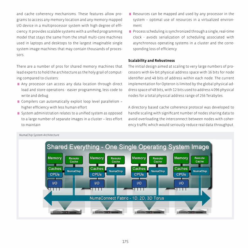
175
� Resources can be mapped and used by any processor in the
system – optimal use of resources in a virtualized environ-
ment
� Process scheduling is synchronized through a single, real-time
clock - avoids serialization of scheduling associated with
asynchronous operating systems in a cluster and the corre-
sponding loss of efficiency
Scalability and Robustness
The initial design aimed at scaling to very large numbers of pro-
cessors with 64-bit physical address space with 16 bits for node
identifier and 48 bits of address within each node. The current
implementation for Opteron is limited by the global physical ad-
dress space of 48 bits, with 12 bits used to address 4 096 physical
nodes for a total physical address range of 256 Terabytes.
A directory based cache coherence protocol was developed to
handle scaling with significant number of nodes sharing data to
avoid overloading the interconnect between nodes with coher-
ency traffic which would seriously reduce real data throughput.
and cache coherency mechanisms. These features allow pro-
grams to access any memory location and any memory mapped
I/O device in a multiprocessor system with high degree of effi-
ciency. It provides scalable systems with a unified programming
model that stays the same from the small multi-core machines
used in laptops and desktops to the largest imaginable single
system image machines that may contain thousands of proces-
sors.
There are a number of pros for shared memory machines that
lead experts to hold the architecture as the holy grail of comput-
ing compared to clusters:
� Any processor can access any data location through direct
load and store operations - easier programming, less code to
write and debug
� Compilers can automatically exploit loop level parallelism –
higher efficiency with less human effort
� System administration relates to a unified system as opposed
to a large number of separate images in a cluster – less effort
to maintain
NumaChip System Architecture
176
The basic ring topology with distributed switching allows a
number of different interconnect configurations that are more
scalable than most other interconnect switch fabrics. This also
eliminates the need for a centralized switch and includes inher-
ent redundancy for multidimensional topologies.
Functionality is included to manage robustness issues associ-
ated with high node counts and extremely high requirements
for data integrity with the ability to provide high availability for
systems managing critical data in transaction processing and
realtime control. All data that may exist in only one copy are ECC
protected with automatic scrubbing after detected single bit
errors and automatic background scrubbing to avoid accumula-
tion of single bit errors.
Integrated, distributed switching
NumaChip contains an on-chip switch to connect to other nodes
in a NumaChip based system, eliminating the need to use a
centralized switch. The on-chip switch can connect systems in
one, two or three dimensions. Small systems can use one, medi-
um-sized system two and large systems will use all three dimen-
sions to provide efficient and scalable connectivity between
processors.
The two- and three-dimensional topologies (called Torus) also
have the advantage of built-in redundancy as opposed to sys-
tems based on centralized switches, where the switch repre-
sents a single point of failure.
The distributed switching reduces the cost of the system since
there is no extra switch hardware to pay for. It also reduces the
amount of rack space required to hold the system as well as the
power consumption and heat dissipation from the switch hard-
ware and the associated power supply energy loss and cooling
requirements.
Numascale
Technology
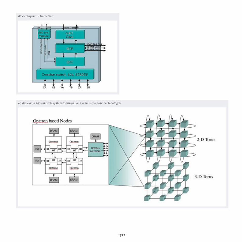
177
Block Diagram of NumaChip
Multiple links allow flexible system configurations in multi-dimensional topologies
S
N
EW
SESW
NENW
tech BOX
178
Numascale
Redefining Scalable OpenMP and MPI
Redefining Scalable OpenMP and MPI Shared Memory Advantages
Multi-processor shared memory processing has long been the
preferred method for creating and running technical computing
codes. Indeed, this computing model now extends from a user’s
dual core laptop to 16+ core servers. Programmers often add
parallel OpenMP directives to their programs in order to take
advantage of the extra cores on modern servers. This approach
is flexible and often preserves the “sequential” nature of the
program (pthreads can of course also be used, but OpenMP is
much easier to use). To extend programs beyond a single server,
however, users must use the Message Passing Interface (MPI) to
allow the program to operate across a high-speed interconnect.
Interestingly, the advent of multi-core servers has created a par-
allel asymmetric computing model, where programs must map
themselves to networks of shared memory SMP servers. This
asymmetric model introduces two levels of communication,
local within a node, and distant to other nodes. Programmers
often create pure MPI programs that run across multiple cores
on multiple nodes. While a pure MPI program does represent
the greatest common denominator, better performance may be
sacrificed by not utilizing the local nature of multi-core nodes.
Hybrid (combined MPI/OpenMP) models have been able to pull
more performance from cluster hardware, but often introduce
programming complexity and may limit portability.Clearly, us-
ers prefer writing software for large shared memory systems to
MPI programming. This preference becomes more pronounced
when large data sets are used. In a large SMP system the data
are simply used in place, whereas in a distributed memory clus-
ter the dataset must be partitioned across compute nodes.
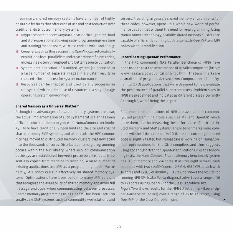
179
In summary, shared memory systems have a number of highly
desirable features that offer ease of use and cost reduction over
traditional distributed memory systems:
� Any processor can access any data location through direct load
and store operations, allowing easier programming (less time
and training) for end users, with less code to write and debug.
� Compilers, such as those supporting OpenMP, can automatically
exploit loop level parallelism and create more efficient codes,
increasing system throughput and better resource utilization.
� System administration of a unified system (as opposed to
a large number of separate images in a cluster) results in
reduced effort and cost for system maintenance.
� Resources can be mapped and used by any processor in
the system, with optimal use of resources in a single image
operating system environment.
Shared Memory as a Universal Platform
Although the advantages of shared memory systems are clear,
the actual implementation of such systems “at scale” has been
difficult prior to the emergence of NumaConnect technolo-
gy. There have traditionally been limits to the size and cost of
shared memory SMP systems, and as a result the HPC commu-
nity has moved to distributed memory clusters that now scale
into the thousands of cores. Distributed memory programming
occurs within the MPI library, where explicit communication
pathways are established between processors (i.e., data is es-
sentially copied from machine to machine). A large number of
existing applications use MPI as a programming model. Fortu-
nately, MPI codes can run effectively on shared memory sys-
tems. Optimizations have been built into many MPI versions
that recognize the availability of shared memory and avoid full
message protocols when communicating between processes.
Shared memory programming using OpenMP has been useful on
small-scale SMP systems such as commodity workstations and
servers. Providing large-scale shared memory environments for
these codes, however, opens up a whole new world of perfor-
mance capabilities without the need for re-programming. Using
NumaConnect technology, scalable shared memory clusters are
capable of efficiently running both large-scale OpenMP and MPI
codes without modification.
Record-Setting OpenMP Performance
In the HPC community NAS Parallel Benchmarks (NPB) have
been used to test the performance of parallel computers (http://
www.nas.nasa.gov/publications/npb.html). The benchmarks are
a small set of programs derived from Computational Fluid Dy-
namics (CFD) applications that were designed to help evaluate
the performance of parallel supercomputers. Problem sizes in
NPB) are predefined and indicated as different classes (currently
A through F, with F being the largest).
Reference implementations of NPB are available in common-
ly-used programming models such as MPI and OpenMP, which
make them ideal for measuring the performance of both distrib-
uted memory and SMP systems. These benchmarks were com-
piled with Intel ifort version 14.0.0. (Note: the current-generated
code is slightly faster, but Numascale is working on NumaCon-
nect optimizations for the GNU compilers and thus suggests
using gcc and gfortran for OpenMP applications.) For the follow-
ing tests, the NumaConnect Shared Memory benchmark system
has 1TB of memory and 256 cores. It utilizes eight servers, each
equipped with two x AMD Opteron 2.5 GHz 6380 CPUs, each with
16 cores and 128GB of memory. Figure One shows the results for
running NPB-SP (Scalar Penta-diagonal solver) over a range of 16
to 121 cores using OpenMP for the Class D problem size.
Figure Two shows results for the NPB-LU benchmark (Lower-Up-
per Gauss-Seidel solver) over a range of 16 to 121 cores, using
OpenMP for the Class D problem size.
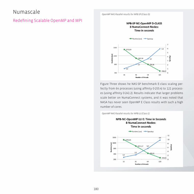
180
Figure Three shows he NAS-SP benchmark E-class scaling per-
fectly from 64 processes (using affinity 0-255:4) to 121 process-
es (using affinity 0-241:2). Results indicate that larger problems
scale better on NumaConnect systems, and it was noted that
NASA has never seen OpenMP E Class results with such a high
number of cores.
OpenMP NAS Parallel results for NPB-SP (Class D)
OpenMP NAS Parallel results for NPB-LU (Class E)
Numascale
Redefining Scalable OpenMP and MPI

181
OpenMP applications cannot run on InfinBand clusters without
additional software layers and kernel modifications. The Numa-
Connect cluster runs a standard Linux kernel image.
Surprisingly Good MPI Performance
Despite the excellent OpenMP shared memory performance
that NumaConnect can deliver, applications have historically
been written using MPI. The performance of these applications
is presented below. As mentioned, the NumaConnect system
can easily run MPI applications.
Figure Four is a comparison of NumaConnect and FDR InfiniB-
and NPB-SP (Class D). The results indicate that NumaConnect
performance is superior to that of a traditional distributed In-
finiBand memory cluster. MPI tests were run with OpenMPI and
gfortran 4.8.1 using the same hardware mentioned above.
Both industry-standard OpenMPI and MPICH2 work in shared
memory mode. Numascale has implemented their own version
of the OpenMPI BTL (Byte Transfer Layer) to optimize the com-
munication by utilizing non-polluting store instructions. MPI
messages require data to be moved, and in a shared memory en-
vironment there is no reason to use standard instructions that
implicitly result in cache pollution and reduced performance.
This results in very efficient message passing and excellent MPI
performance.
Similar results are shown in Figure Five for the NAS-LU (Class D).
NumaConnect’s performance over InfiniBand may be one of the
more startling results for the NAS benchmarks. Recall again that
OpenMP applications cannot run on InfiniBand clusters without
additional software layers and kernel modifications.
OpenMP NAS results for NPB-SP (Class E)
NPB-SP comparison of NumaConnect to FDI InfiniBand
NPB-LU comparison of NumaConnect to FDI InfiniBand
S
N
EW
SESW
NENW
tech BOX
182
Numascale
Big Data
Big Data Big Data applications – once limited to a few exotic disciplines
– are steadily becoming the dominant feature of modern com-
puting. In industry after industry, massive datasets are being
generated by advanced instruments and sensor technology.
Consider just one example, next generation DNA sequencing
(NGS). Annual NGS capacity now exceeds 13 quadrillion base
pairs (the As, Ts, Gs, and Cs that make up a DNA sequence). Each
base pair represents roughly 100 bytes of data (raw, analyzed,
and interpreted). Turning the swelling sea of genomic data into
useful biomedical information is a classic Big Data challenge,
one of many, that didn’t exist a decade ago.
This mainstreaming of Big Data is an important transformational
moment in computation. Datasets in the 10-to-20 Terabytes (TB)
range are increasingly common. New and advanced algorithms
for memory-intensive applications in Oil & Gas (e.g. seismic data
processing), finance (real-time trading) social media (database),
and science (simulation and data analysis), to name but a few,
are hard or impossible to run efficiently on commodity clusters.
The challenge is that traditional cluster computing based on
distributed memory – which was so successful in bringing down
the cost of high performance computing (HPC) – struggles when
forced to run applications where memory requirements exceed
the capacity of a single node. Increased interconnect latencies,
longer and more complicated software development, inefficient
system utilization, and additional administrative overhead are
all adverse factors. Conversely, traditional mainframes running
shared memory architecture and a single instance of the OS have
always coped well with Big Data Crunching jobs.
183
Numascale’s SolutionUntil now, the biggest obstacle to wider use of shared memory
computing has been the high cost of mainframes and high-end
‘super-servers’. Given the ongoing proliferation of Big Data appli-
cations, a more efficient and cost-effective approach to shared
memory computing is needed. Now, Numascale, a four-year-old
spin-off from Dolphin Interconnect Solutions, has developed a
technology, NumaConnect, which turns a collection of standard
servers with separate memories and IO into a unified system
that delivers the functionality of high-end enterprise servers and
mainframes at a fraction of the cost.
Numascale Technology snapshot (board and chip):
NumaConnect links commodity servers together to form a single
unified system where all processors can coherently access and
share all memory and I/O. The combined system runs a single
instance of a standard operating system like Linux. At the heart
of NumaConnect is NumaChip – a single chip that combines the
cache coherent shared memory control logic with an on-chip
7-way switch. This eliminates the need for a separate, central
switch and enables linear capacity and cost scaling.
Systems based on NumaConnect support all classes of applica-
tions using shared memory or message passing through all pop-
ular high level programming models. System size can be scaled
to 4k nodes where each node can contain multiple processors.
Memory size is limited only by the 48-bit physical address range
provided by the Opteron processors resulting in a record-break-
ing total system main memory of 256 TBytes. (For details of Nu-
mascale technology see: The NumaConnect White Paper)
The result is an affordable, shared memory computing option to
tackle data-intensive applications. NumaConnect-based systems
running with entire data sets in memory are “orders of magni-
tude faster than clusters or systems based on any form of existing
mass storage devices and will enable data analysis and decision
support applications to be applied in new and innovative ways,”
says Kåre Løchsen, Numascale founder and CEO.
The big differentiator for NumaConnect compared to other high-
speed interconnect technologies is the shared memory and
cache coherency mechanisms. These features allow programs to
access any memory location and any memory mapped I/O device
in a multiprocessor system with high degree of efficiency. It pro-
vides scalable systems with a unified programming model that
stays the same from the small multi-core machines used in lap-
tops and desktops to the largest imaginable single system image
machines that may contain thousands of processors and tens to
hundreds of terabytes of main memory.
Early adopters are already demonstrating performance gains
and costs savings. A good example is Statoil, the global energy
company based in Norway. Processing seismic data requires
massive amounts of floating point operations and is normally
performed on clusters. Broadly speaking, this kind of processing
is done by programs developed for a message-passing paradigm
(MPI). Not all algorithms are suited for the message passing para-
digm and the amount of code required is huge and the develop-
ment process and debugging task are complex.
Numascale’s implementation of shared memory has many inno-
vations. Its on-chip switch, for example, can connect systems in
one, two, or three dimensions (e.g. 2D and 3D Torus). Small sys-
tems can use one, medium sized system two, and large systems
will use all three dimensions to provide efficient and scalable
connectivity between processors. The distributed switching re-
duces the cost of the system since there is no extra switch hard-
ware to pay for. It also reduces the amount of rack space required
to hold the system as well as the power consumption and heat
dissipation from the switch hardware and the associated power
supply energy loss and cooling requirements.

S
N
EW
SESW
NENW
tech BOX
184
Numascale
Cache Coherence
Cache Coherence Multiprocessor systems with caches and shared memory space
need to resolve the problem of keeping shared data coherent.
This means that the most recently written data to a memory lo-
cation from one processor needs to be visible to other proces-
sors in the system immediately after a synchronization point.
The synchronization point is normally implemented as a barrier
through a lock (semaphore) where the process that stores data
releases a lock after finishing the store sequence.
When the lock is released, the most recent version of the data
that was stored by the releasing process can be read by another
process. If there were no individual caches or buffers in the data
paths between processors and the shared memory system, this
would be a relatively trivial task. The presence of caches chang-
es this picture dramatically. Even if the caches were so-called
write-through, in which case all store operations proceed all
the way to main memory, it would still mean that the proces-
sor wanting to read shared data could have copies of previous
185
versions of the data in the cache and such a read operation
would return a stale copy seen from the producer process un-
less certain steps are taken to avoid the problem.
Early cache systems would simply require a cache clear opera-
tion to be issued before reading the shared memory buffer in
which case the reading process would encounter cache misses
and automatically fetch the most recent copy of the data from
main memory. This could be done without too much loss of per-
formance when the speed difference between memory, cache
and processors was relatively small.
As these differences grew and write-back caches were intro-
duced, such coarse-grained coherency mechanisms were no
longer adequate. A write-back cache will only store data back
to main memory upon cache line replacements, i.e. when the
cache line will be replaced due to a cache miss of some sort. To
accommodate this functionality, a new cache line state, “dirty”,
was introduced in addition to the traditional “hit/miss” states.
S
N
EW
SESW
NENW
tech BOX
186
Numascale
NUMA and ccNUMA
NUMA and ccNUMA The term Non-Uniform Memory Access means that memory
accesses from a given processor in a multiprocessor system will
have different access time depending on the physical location
of the memory. The “cc” means Cache Coherence, (i.e. all memory
references from all processors will return the latest updated
data from any cache in the system automatically.)
Modern multiprocessor systems where processors are con-
nected through a hierarchy of interconnects (or buses) will per-
form differently depending on the relative physical location of
processors and the memory being accessed. Most small multi-
processor systems used to be symmetric (SMP – Symmetric Mul-
ti-Processor) having a couple of processors hooked up to a main
memory system through a central bus where all processors had
equal priority and the same distance from the memory.
This was changed through AMD’s introduction of Hypertrans-
port with on-chip DRAM controllers. When more than one such
processor chip (normally also with multiple CPU cores per chip)
are connected, the criteria for being categorized as NUMA are
fulfilled. This is illustrated by the fact that reading or writing
data from or to the local memory is indeed quite a bit faster
than performing the same operations on the memory that is
controlled by the other processor chip.
Seen from a programming point of view, the uniform, global
shared address space is a great advantage since any operand or
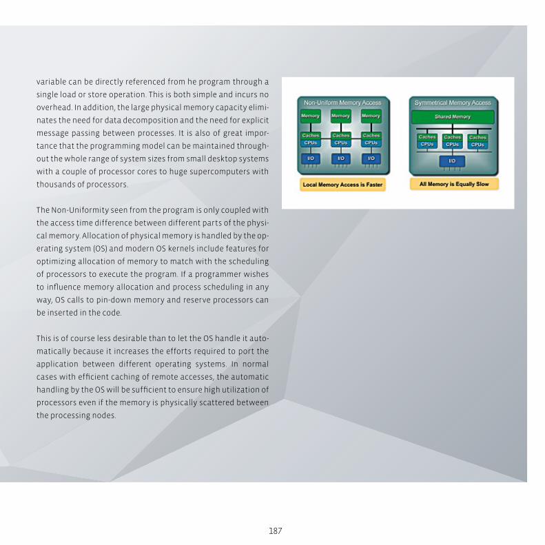
187
variable can be directly referenced from he program through a
single load or store operation. This is both simple and incurs no
overhead. In addition, the large physical memory capacity elimi-
nates the need for data decomposition and the need for explicit
message passing between processes. It is also of great impor-
tance that the programming model can be maintained through-
out the whole range of system sizes from small desktop systems
with a couple of processor cores to huge supercomputers with
thousands of processors.
The Non-Uniformity seen from the program is only coupled with
the access time difference between different parts of the physi-
cal memory. Allocation of physical memory is handled by the op-
erating system (OS) and modern OS kernels include features for
optimizing allocation of memory to match with the scheduling
of processors to execute the program. If a programmer wishes
to influence memory allocation and process scheduling in any
way, OS calls to pin-down memory and reserve processors can
be inserted in the code.
This is of course less desirable than to let the OS handle it auto-
matically because it increases the efforts required to port the
application between different operating systems. In normal
cases with efficient caching of remote accesses, the automatic
handling by the OS will be sufficient to ensure high utilization of
processors even if the memory is physically scattered between
the processing nodes.

Engi
nee
rin
g L
ife
Scie
nce
s A
uto
mo
tive
P
rice
Mo
del
lin
g A
ero
spac
e C
AE
Dat
a A
nal
ytic
s
IBM Platform HPC –Enterprise-Ready Cluster & Workload Management
High performance computing (HPC) is becoming a necessary tool for organizations to
speed up product design, scientific research, and business analytics. However, there
are few software environments more complex to manage and utilize than modern high
performance computing clusters.
Therefore, addressing the problem of complexity in cluster management is a key aspect
of leveraging HPC to improve time to results and user productivity.
190
IntroductionClusters based on the Linux operating system have become in-
creasingly prevalent at large supercomputing centers and con-
tinue to make significant in-roads in commercial and academic
settings. This is primarily due to their superior price/performance
and flexibility, as well as the availability of commercial applica-
tions that are based on the Linux OS.
Ironically, the same factors that make Linux a clear choice for
high performance computing often make the operating system
less accessible to smaller computing centers. These organiza-
tions may have Microsoft Windows administrators on staff, but
have little or no Linux or cluster management experience. The
complexity and cost of cluster management often outweigh the
benefits that make open, commodity clusters so compelling. Not
only can HPC cluster deployments be difficult, but the ongoing
need to deal with heterogeneous hardware and operating sys-
tems, mixed workloads, and rapidly evolving toolsets make de-
ploying and managing an HPC cluster a daunting task.
These issues create a barrier to entry for scientists and research-
ers who require the performance of an HPC cluster, but are limit-
ed to the performance of a workstation. This is why ease of use is
now mandatory for HPC cluster management. This paper reviews
the most complete and easy to use cluster management solu-
tion, Platform HPC, which is now commercially available from
Platform Computing.
The cluster management challengeTo provide a proper HPC application environment, system admin-
istrators need to provide a full set of capabilities to their users,
as shown below. These capabilities include cluster provisioning
and node management, application workload management, and
an environment that makes it easy to develop, run and manage
distributed parallel applications.
Modern application environments tend to be heterogeneous;
some workloads require Windows compute hosts while others
IBM Platform HPC
Enterprise-Ready Cluster &
Workload Management
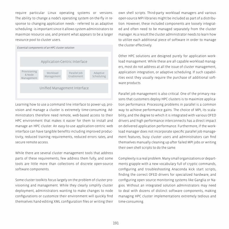
Application-Centric Interface
Unified Management Interface
Provisioning& Node
Management
WorkloadManagement
Parallel JobEnablement
AdaptiveScheduling
191
require particular Linux operating systems or versions.
The ability to change a node’s operating system on-the-fly in re-
sponse to changing application needs - referred to as adaptive
scheduling - is important since it allows system administrators to
maximize resource use, and present what appears to be a larger
resource pool to cluster users.
Learning how to use a command line interface to power-up, pro-
vision and manage a cluster is extremely time-consuming. Ad-
ministrators therefore need remote, web-based access to their
HPC environment that makes it easier for them to install and
manage an HPC cluster. An easy-to-use application-centric web
interface can have tangible benefits including improved produc-
tivity, reduced training requirements, reduced errors rates, and
secure remote access.
While there are several cluster management tools that address
parts of these requirements, few address them fully, and some
tools are little more than collections of discrete open-source
software components.
Some cluster toolkits focus largely on the problem of cluster pro-
visioning and management. While they clearly simplify cluster
deployment, administrators wanting to make changes to node
configurations or customize their environment will quickly find
themselves hand-editing XML configuration files or writing their
own shell scripts. Third-party workload managers and various
open-source MPI libraries might be included as part of a distribu-
tion. However, these included components are loosely integrat-
ed and often need to be managed separately from the cluster
manager. As a result the cluster administrator needs to learn how
to utilize each additional piece of software in order to manage
the cluster effectively.
Other HPC solutions are designed purely for application work-
load management. While these are all capable workload manag-
ers, most do not address at all the issue of cluster management,
application integration, or adaptive scheduling. If such capabil-
ities exist they usually require the purchase of additional soft-
ware products.
Parallel job management is also critical. One of the primary rea-
sons that customers deploy HPC clusters is to maximize applica-
tion performance. Processing problems in parallel is a common
way to achieve performance gains. The choice of MPI, its scala-
bility, and the degree to which it is integrated with various OFED
drivers and high performance interconnects has a direct impact
on delivered application performance. Furthermore, if the work-
load manager does not incorporate specific parallel job manage-
ment features, busy cluster users and administrators can find
themselves manually cleaning up after failed MPI jobs or writing
their own shell scripts to do the same.
Complexity is a real problem. Many small organizations or depart-
ments grapple with a new vocabulary full of cryptic commands,
configuring and troubleshooting Anaconda kick start scripts,
finding the correct OFED drivers for specialized hardware, and
configuring open source monitoring systems like Ganglia or Na-
gios. Without an integrated solution administrators may need
to deal with dozens of distinct software components, making
managing HPC cluster implementations extremely tedious and
time-consuming.
Essential components of an HPC cluster solution
192
Re-thinking HPC clustersClearly these challenges demand a fresh approach to HPC cluster
management. Platform HPC represents a “re-think” of how HPC
clusters are deployed and managed. Rather than addressing only
part of the HPC management puzzle, Platform HPC addresses all
facets of cluster management. It provides:
� A complete, easy-to-use cluster management solution
� Integrated application support
� User-friendly, topology-aware workload management
� Robust workload and system monitoring and reporting
� Dynamic operating system multi-boot (adaptive scheduling)
� GPU scheduling
� Robust commercial MPI library (Platform MPI)
�Web-based interface for access anywhere
Most complete HPC cluster management solution
Platform HPC makes it easy to deploy, run and manage HPC clusters
while meeting the most demanding requirements for application
performance and predictable workload management. It is a com-
plete solution that provides a robust set of cluster management
capabilities; from cluster provisioning and management to work-
load management and monitoring. The easy-to -use unified web
portal provides a single point of access into the cluster, making it
easy to manage your jobs and optimize application performance.
Platform HPC is more than just a stack of software; it is a fully
integrated and certified solution designed to ensure ease of use
and simplified troubleshooting.
Integrated application support
High performing, HPC-optimized MPI libraries come integrated
with Platform HPC, making it easy to get parallel applications up
and running. Scripting guidelines and job submission templates
for commonly used commercial applications simplify job submis-
sion, reduce setup time and minimize operation errors. Once the ap-
plications are up and running, Platform HPC improves application
“Platform HPC and Platform LSF have been known for many years as
a highest-quality and enterprise-ready cluster and workload man-
agement solutions, and we have many customers in academia and
industry relying on them.”
Robin KieneckerHPC Sales Specialist
IBM Platform HPC
Enterprise-Ready Cluster &
Workload Management
193
performance by intelligently scheduling resources based on
workload characteristics.
Fully certified and supported
Platform HPC unlocks cluster management to provide the easiest
and most complete HPC management capabilities while reducing
overall cluster cost and improving administrator productivity. It is
based on the industry’s most mature and robust workload manager,
Platform LSF, making it the most reliable solution on the market.
Other solutions are typically a collection of open-source tools, which
may also include pieces of commercially developed software. They
lack key HPC functionality and vendor support, relying on the ad-
ministrator’s technical ability and time to implement. Platform HPC
is a single product with a single installer and a unified web-based
management interface. With the best support in the HPC industry,
Platform HPC provides the most complete solution for HPC cluster
management.
Complete solutionPlatform HPC provides a complete set of HPC cluster manage-
ment features. In this section we’ll explore some of these unique
capabilities in more detail.
Easy to use, cluster provisioning and management
With Platform HPC, administrators can quickly provision and
manage HPC clusters with unprecedented ease. It ensures max-
imum uptime and can transparently synchronize files to cluster
nodes without any downtime or re-installation.
Fast and efficient software Installation – Platform HPC can be
installed on the head node and takes less than one hour using
three different mechanisms:
� Platform HPC DVD
� Platform HPC ISO file
� Platform partner’s factory install bootable USB drive
Installing software on cluster nodes is simply a matter of associ-
ating cluster nodes with flexible provisioning templates through
the web-based interface.
Flexible provisioning – Platform HPC offers multiple options for
provisioning Linux operating environments that include:
� Package-based provisioning
� Image based provisioning
� Diskless node provisioning
Large collections of hosts can be provisioned using the same pro-
visioning template. Platform HPC automatically manages details
such as IP address assignment and node naming conventions
that reflect the position of cluster nodes in data center racks.
Unlike competing solutions, Platform HPC deploys multiple op-
erating systems and OS versions to a cluster simultaneously. This
includes Red Hat Enterprise Linux, CentOS, Scientific Linux, and
SUSE Linux Enterprise Server. This provides administrators with
greater flexibility in how they serve their user communities and
means that HPC clusters can grow and evolve incrementally as
requirements change.
S
N
EW
SESW
NENW
tech BOX
194
IBM Platform HPC
What’s New in IBM Platform LSF 8
What’s New in IBM Platform LSF 8 Written with Platform LSF administrators in mind, this brief pro-
vides a short explanation of significant changes in Platform’s lat-
est release of Platform LSF, with a specific emphasis on schedul-
ing and workload management features.
About IBM Platform LSF 8Platform LSF is the most powerful workload manager for de-
manding, distributed high performance computing environ-
ments. It provides a complete set of workload management ca-
pabilities, all designed to work together to reduce cycle times
and maximize productivity in missioncritical environments.
This latest Platform LSF release delivers improvements in perfor-
mance and scalability while introducing new features that sim-
plify administration and boost user productivity. This includes:
� Guaranteed resources – Aligns business SLA’s with infra-
structure configuration for simplified administration and
configuration
� Live reconfiguration – Provides simplified administration
and enables agility
� Delegation of administrative rights – Empowers line of busi-
ness owners to take control of their own projects
� Fairshare & pre-emptive scheduling enhancements – Fine
tunes key production policies
195
Platform LSF 8 FeaturesGuaranteed Resources Ensure Deadlines are Met
In Platform LSF 8, resource-based scheduling has been extended
to guarantee resource availability to groups of jobs. Resources
can be slots, entire hosts or user-defined shared resources such
as software licenses.
As an example, a business unit might guarantee that it has access
to specific types of resources within ten minutes of a job being
submitted, even while sharing resources between departments.
This facility ensures that lower priority jobs using the needed re-
sources can be pre-empted in order to meet the SLAs of higher
priority jobs. Because jobs can be automatically attached to an
SLA class via access controls, administrators can enable these
guarantees without requiring that end-users change their job
submission procedures, making it easy to implement this capa-
bility in existing environments.
Live Cluster Reconfiguration
Platform LSF 8 incorporates a new live reconfiguration capabil-
ity, allowing changes to be made to clusters without the need
to re-start LSF daemons. This is useful to customers who need
to add hosts, adjust sharing policies or re-assign users between
groups “on the fly”, without impacting cluster availability or run-
ning jobs.
Changes to the cluster configuration can be made via the bconf
command line utility, or via new API calls. This functionality can
also be integrated via a web-based interface using Platform Ap-
plication Center. All configuration modifications are logged for
a complete audit history, and changes are propagated almost
instantaneously. The majority of reconfiguration operations are
completed in under half a second.
With Live Reconfiguration, down-time is reduced, and adminis-
trators are free to make needed adjustments quickly rather than
wait for scheduled maintenance periods or non-peak hours. In
cases where users are members of multiple groups, controls can
be put in place so that a group administrator can only control
jobs associated with their designated group rather than impact-
ing jobs related to another group submitted by the same user.
Delegation of Administrative Rights
With Platform LSF 8, the concept of group administrators has
been extended to enable project managers and line of business
managers to dynamically modify group membership and fair-
share resource allocation policies within their group. The ability
to make these changes dynamically to a running cluster is made
possible by the Live Reconfiguration feature.
These capabilities can be delegated selectively depending on the
group and site policy. Different group administrators can man-
age jobs, control sharing policies or adjust group membership.

196
More Flexible Fairshare Scheduling Policies
To enable better resource sharing flexibility with Platform LSF 8,
the algorithms used to tune dynamically calculated user priori-
ties can be adjusted at the queue level. These algorithms can vary
based on department, application or project team preferences.
The Fairshare parameters ENABLE_HIST_RUN_TIME and HIST_
HOURS enable administrators to control the degree to which LSF
considers prior resource usage when determining user priority.
The flexibility of Platform LSF 8 has also been improved by al-
lowing a similar “decay rate” to apply to currently running jobs
(RUN_TIME_DECAY), either system-wide or at the queue level.
This is most useful for customers with long-running jobs, where
setting this parameter results in a more accurate view of real re-
source use for the fairshare scheduling to consider.
Performance & Scalability Enhancements
Platform LSF has been extended to support an unparalleled
scale of up to 100,000 cores and 1.5 million queued jobs for
very high throughput EDA workloads. Even higher scalability is
possible for more traditional HPC workloads. Specific areas of im-
provement include the time required to start the master-batch
daemon (MBD), bjobs query performance, job submission and
job dispatching as well as impressive performance gains result-
ing from the new Bulk Job Submission feature. In addition, on
very large clusters with large numbers of user groups employing
fairshare scheduling, the memory footprint of the master batch
scheduler in LSF has been reduced by approximately 70% and
scheduler cycle time has been reduced by 25%, resulting in better
performance and scalability.
IBM Platform HPC
What’s New in IBM Platform LSF 8
197
More Sophisticated Host-based Resource Usage for Parallel Jobs
Platform LSF 8 provides several improvements to how resource
use is tracked and reported with parallel jobs. Accurate tracking
of how parallel jobs use resources such as CPUs, memory and
swap, is important for ease of management, optimal scheduling
and accurate reporting and workload analysis. With Platform LSF
8 administrators can track resource usage on a per-host basis and
an aggregated basis (across all hosts), ensuring that resource use
is reported accurately. Additional details such as running PIDs
and PGIDs for distributed parallel jobs, manual cleanup (if neces-
sary) and the development of scripts for managing parallel jobs
are simplified. These improvements in resource usage reporting
are reflected in LSF commands including bjobs, bhist and bacct.
Improved Ease of Administration for Mixed Windows and
Linux Clusters
The lspasswd command in Platform LSF enables Windows LSF
users to advise LSF of changes to their Windows level passwords.
With Platform LSF 8, password synchronization between envi-
ronments has become much easier to manage because the Win-
dows passwords can now be adjusted directly from Linux hosts
using the lspasswd command. This allows Linux users to conven-
iently synchronize passwords on Windows hosts without need-
ing to explicitly login into the host.
Bulk Job Submission
When submitting large numbers of jobs with different resource
requirements or job level settings, Bulk Job Submission allows
for jobs to be submitted in bulk by referencing a single file con-
taining job details.

198
Simplified configuration changes – Platform HPC simplifies ad-
ministration and increases cluster availability by allowing chang-
es such as new package installations, patch updates, and changes
to configuration files to be propagated to cluster nodes automat-
ically without the need to re-install those nodes. It also provides a
mechanism whereby experienced administrators can quickly per-
form operations in parallel across multiple cluster nodes.
Repository snapshots / trial installations – Upgrading software
can be risky, particularly in complex environments. If a new soft-
ware upgrade introduces problems, administrators often need to
rapidly “rollback” to a known good state. With other cluster man-
agers this can mean having to re-install the entire cluster. Platform
HPC incorporates repository snapshots, which are “restore points”
for the entire cluster. Administrators can snapshot a known good
repository, make changes to their environment, and easily revert
to a previous “known good” repository in the event of an unfore-
seen problem. This powerful capability takes the risk out of cluster
software upgrades.
New hardware integration – When new hardware is added
to a cluster it may require new or updated device drivers that
are not supported by the OS environment on the installer
node. This means that a newly updated node may not net-
work boot and provision until the head node on the cluster is
updated with a new operating system; a tedious and disrup-
tive process. Platform HPC includes a driver patching utility
that allows updated device drivers to be inserted into exist-
ing repositories, essentially future proofing the cluster, and
providing a simplified means of supporting new hardware
without needing to re-install the environment from scratch.
Software updates with no re-boot – Some cluster managers al-
ways re-boot nodes when updating software, regardless of how
minor the change. This is a simple way to manage updates. Howev-
er, scheduling downtime can be difficult and disruptive. Platform
IBM Platform HPC
Enterprise-Ready Cluster &
Workload Management
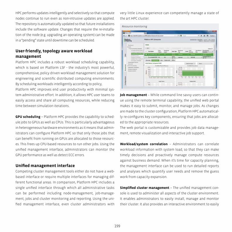
199
HPC performs updates intelligently and selectively so that compute
nodes continue to run even as non-intrusive updates are applied.
The repository is automatically updated so that future installations
include the software update. Changes that require the re-installa-
tion of the node (e.g. upgrading an operating system) can be made
in a “pending” state until downtime can be scheduled.
User-friendly, topology aware workload managementPlatform HPC includes a robust workload scheduling capability,
which is based on Platform LSF - the industry’s most powerful,
comprehensive, policy driven workload management solution for
engineering and scientific distributed computing environments.
By scheduling workloads intelligently according to policy,
Platform HPC improves end user productivity with minimal sys-
tem administrative effort. In addition, it allows HPC user teams to
easily access and share all computing resources, while reducing
time between simulation iterations.
GPU scheduling – Platform HPC provides the capability to sched-
ule jobs to GPUs as well as CPUs. This is particularly advantageous
in heterogeneous hardware environments as it means that admin-
istrators can configure Platform HPC so that only those jobs that
can benefit from running on GPUs are allocated to those resourc-
es. This frees up CPU-based resources to run other jobs. Using the
unified management interface, administrators can monitor the
GPU performance as well as detect ECC errors.
Unified management interfaceCompeting cluster management tools either do not have a web-
based interface or require multiple interfaces for managing dif-
ferent functional areas. In comparison, Platform HPC includes a
single unified interface through which all administrative tasks
can be performed including node-management, job-manage-
ment, jobs and cluster monitoring and reporting. Using the uni-
fied management interface, even cluster administrators with
very little Linux experience can competently manage a state of
the art HPC cluster.
Job management – While command line savvy users can contin-
ue using the remote terminal capability, the unified web portal
makes it easy to submit, monitor, and manage jobs. As changes
are made to the cluster configuration, Platform HPC automatical-
ly re-configures key components, ensuring that jobs are allocat-
ed to the appropriate resources.
The web portal is customizable and provides job data manage-
ment, remote visualization and interactive job support.
Workload/system correlation – Administrators can correlate
workload information with system load, so that they can make
timely decisions and proactively manage compute resources
against business demand. When it’s time for capacity planning,
the management interface can be used to run detailed reports
and analyses which quantify user needs and remove the guess
work from capacity expansion.
Simplified cluster management – The unified management con-
sole is used to administer all aspects of the cluster environment.
It enables administrators to easily install, manage and monitor
their cluster. It also provides an interactive environment to easily
Resource monitoring
200
package software as kits for application deployment as well as
pre-integrated commercial application support. One of the key
features of the interface is an operational dashboard that pro-
vides comprehensive administrative reports. As the image illus-
trates, Platform HPC enables administrators to monitor and report
on key performance metrics such as cluster capacity, available
memory and CPU utilization. This enables administrators to easily
identify and troubleshoot issues. The easy to use interface saves
the cluster administrator time, and means that they do not need to
become an expert in the administration of open-source software
components. It also reduces the possibility of errors and time lost
due to incorrect configuration. Cluster administrators enjoy the
best of both worlds – easy access to a powerful, web-based cluster
manager without the need to learn and separately administer all
the tools that comprise the HPC cluster environment.
Robust Commercial MPI libraryPlatform MPI – In order to make it easier to get parallel applica-
tions up and running, Platform HPC includes the industry’s most
robust and highest performing MPI implementation, Platform MPI.
Platform MPI provides consistent performance at application run-
time and for application scaling, resulting in top performance re-
sults across a range of third-party benchmarks.
Open Source MPI – Platform HPC also includes various other in-
dustry standard MPI implementations. This includes MPICH1,
MPICH2 and MVAPICH1, which are optimized for cluster hosts con-
nected via InfiniBand, iWARP or other RDMA based interconnects.
Integrated application supportJob submission templates – Platform HPC comes complete with
job submission templates for ANSYS Mechanical, ANSYS Fluent,
ANSYS CFX, LS-DYNA, MSC Nastran, Schlumberger ECLIPSE, Sim-
ulia Abaqus, NCBI Blast, NWChem, ClustalW, and HMMER. By
configuring these templates based on the application settings
in your environment, users can start using the cluster without
writing scripts.
IBM Platform HPC
Enterprise-Ready Cluster &
Workload Management
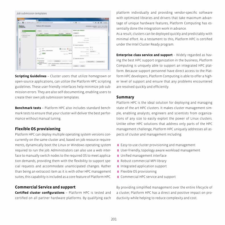
201
Scripting Guidelines – Cluster users that utilize homegrown or
open-source applications, can utilize the Platform HPC scripting
guidelines. These user-friendly interfaces help minimize job sub-
mission errors. They are also self-documenting, enabling users to
create their own job submission templates.
Benchmark tests – Platform HPC also includes standard bench-
mark tests to ensure that your cluster will deliver the best perfor-
mance without manual tuning.
Flexible OS provisioningPlatform HPC can deploy multiple operating system versions con-
currently on the same cluster and, based on job resource require-
ments, dynamically boot the Linux or Windows operating system
required to run the job. Administrators can also use a web inter-
face to manually switch nodes to the required OS to meet applica-
tion demands, providing them with the flexibility to support spe-
cial requests and accommodate unanticipated changes. Rather
than being an extracost item as it is with other HPC management
suites, this capability is included as a core feature of Platform HPC.
Commercial Service and supportCertified cluster configurations – Platform HPC is tested and
certified on all partner hardware platforms. By qualifying each
platform individually and providing vendor-specific software
with optimized libraries and drivers that take maximum advan-
tage of unique hardware features, Platform Computing has es-
sentially done the integration work in advance.
As a result, clusters can be deployed quickly and predictably with
minimal effort. As a testament to this, Platform HPC is certified
under the Intel Cluster Ready program.
Enterprise class service and support – Widely regarded as hav-
ing the best HPC support organization in the business, Platform
Computing is uniquely able to support an integrated HPC plat-
form. Because support personnel have direct access to the Plat-
form HPC developers, Platform Computing is able to offer a high-
er level of support and ensure that any problems encountered
are resolved quickly and efficiently.
SummaryPlatform HPC is the ideal solution for deploying and managing
state of the art HPC clusters. It makes cluster management sim-
ple, enabling analysts, engineers and scientists from organiza-
tions of any size to easily exploit the power of Linux clusters.
Unlike other HPC solutions that address only parts of the HPC
management challenge, Platform HPC uniquely addresses all as-
pects of cluster and management including:
� Easy-to-use cluster provisioning and management
� User-friendly, topology aware workload management
� Unified management interface
� Robust commercial MPI library
� Integrated application support
� Flexible OS provisioning
� Commercial HPC service and support
By providing simplified management over the entire lifecycle of
a cluster, Platform HPC has a direct and positive impact on pro-
ductivity while helping to reduce complexity and cost.
Job submission templates
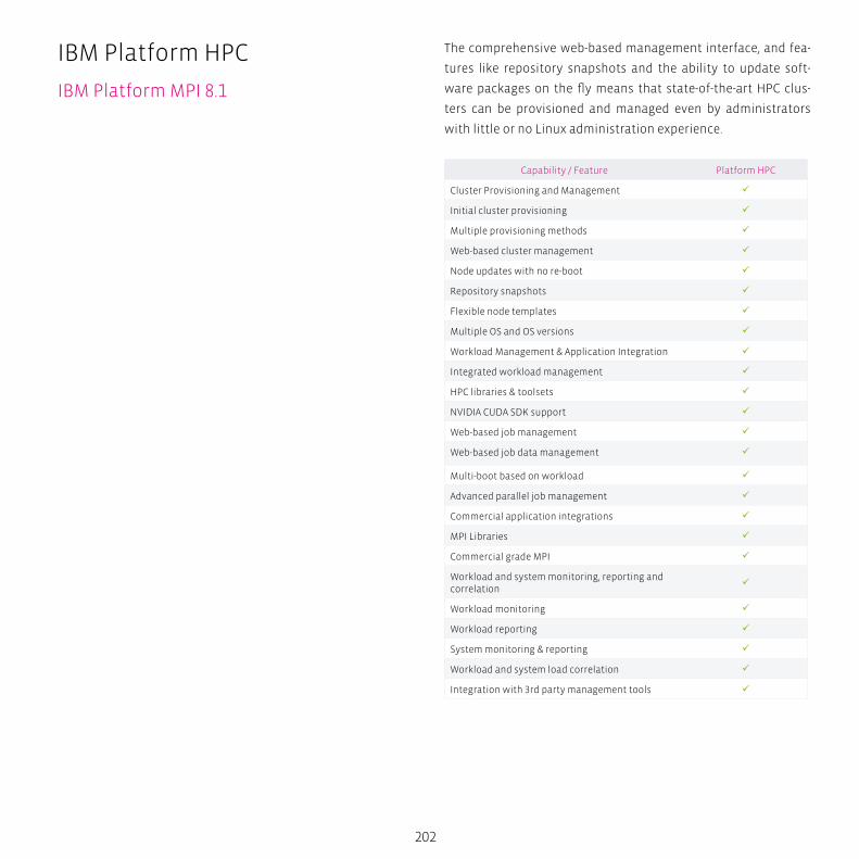
202
The comprehensive web-based management interface, and fea-
tures like repository snapshots and the ability to update soft-
ware packages on the fly means that state-of-the-art HPC clus-
ters can be provisioned and managed even by administrators
with little or no Linux administration experience.
Capability / Feature Platform HPC
Cluster Provisioning and Management
Initial cluster provisioning
Multiple provisioning methods
Web-based cluster management
Node updates with no re-boot
Repository snapshots
Flexible node templates
Multiple OS and OS versions
Workload Management & Application Integration
Integrated workload management
HPC libraries & toolsets
NVIDIA CUDA SDK support
Web-based job management
Web-based job data management
Multi-boot based on workload
Advanced parallel job management
Commercial application integrations
MPI Libraries
Commercial grade MPI
Workload and system monitoring, reporting and correlation
Workload monitoring
Workload reporting
System monitoring & reporting
Workload and system load correlation
Integration with 3rd party management tools
IBM Platform HPC
IBM Platform MPI 8.1
S
N
EW
SESW
NENW
tech BOX
203
IBM Platform MPI 8.1Benefits
� Superior application performance
� Reduced development and support costs
� Faster time-to-market
� The industry’s best technical support
Features � Supports the widest range of hardware, networks and oper-
ating systems
� Distributed by over 30 leading commercial software vendors
� Change interconnects or libraries with no need to re-compile
� Seamless compatibility across Windows and Linux environ-
ments
� Ensures a production quality implementation
Ideal for: � Enterprises that develop or deploy parallelized software ap-
plications on HPC clusters
� Commercial software vendors wanting to improve applica-
tions performance over the widest range of computer hard-
ware, interconnects and operating systems
The Standard for Scalable, Parallel ApplicationsPlatform MPI is a high performance, production–quality imple-
mentation of the Message Passing Interface (MPI). It is widely
used in the high performance computing (HPC) industry and is
considered the de facto standard for developing scalable, parallel
applications. Platform MPI maintains full backward compatibili-
ty with HP-MPI and Platform MPI applications and incorporates
advanced CPU affinity features, dynamic selection of interface
libraries, superior workload manger integrations and improved
performance and scalability.
Platform MPI supports the broadest range of industry standard
platforms, interconnects and operating systems helping ensure
that your parallel applications can run anywhere.
Focus on portabilityPlatform MPI allows developers to build a single executable that
transparently leverages the performance features of any type of
interconnect, thereby providing applications with optimal laten-
cy and bandwidth for each protocol. This reduces development
effort, and enables applications to use the “latest and greatest”
technologies on Linux or Microsoft Windows without the need to
re-compile and re-link applications.
Platform MPI is optimized for both distributed (DMP) and shared
memory (SMP) environments and provides a variety of flexible
CPU binding strategies for processes and threads, enabling bet-
ter performance on multi–core environments. With this capa-
bility memory and cache conflicts are managed by more intelli-
gently distributing the load among multiple cores. With support
for Windows HPC Server 2008 and the Microsoft job scheduler,
as well as other Microsoft operating environments, Platform MPI
allows developers targeting Windows platforms to enjoy the
benefits of a standard portable MPI and avoid proprietary lock-in.

Life
Sci
en
ces
CA
E
Hig
h P
erf
orm
an
ce C
om
pu
tin
g
Big
Da
ta A
na
lyti
cs
Sim
ula
tio
n
CA
D
General Parallel File System (GPFS)Big Data, Cloud Storage it doesn’t matter what you call it, there is certainly increasing
demand to store larger and larger amounts of unstructured data.
The IBM General Parallel File System (GPFSTM) has always been considered a pioneer of
big data storage and continues today to lead in introducing industry leading storage
technologies.
Since 1998 GPFS has lead the industry with many technologies that make the storage
of large quantities of file data possible. The latest version continues in that tradition,
GPFS 3.5 represents a significant milestone in the evolution of big data management.
GPFS 3.5 introduces some revolutionary new features that clearly demonstrate IBM’s
commitment to providing industry leading storage solutions.
206
General Parallel File System (GPFS)
What is GPFS?
What is GPFS?GPFS is more than clustered file system software; it is a full
featured set of file management tools. This includes advanced
storage virtualization, integrated high availability, automated
tiered storage management and the performance to effectively
manage very large quantities of file data.GPFS allows a group of
computers concurrent access to a common set of file data over
a common SAN infrastructure, a network or a mix of connection
types. The computers can run any mix of AIX, Linux or Windows
Server operating systems. GPFS provides storage management,
information life cycle management tools, centralized adminis-
tration and allows for shared access to file systems from remote
GPFS clusters providing a global namespace.
A GPFS cluster can be a single node, two nodes providing a high
availability platform supporting a database application, for ex-
ample, or thousands of nodes used for applications like the mod-
eling of weather patterns. The largest existing configurations ex-
ceed 5,000 nodes. GPFS has been available on since 1998 and has
been field proven for more than 14 years on some of the world’s
most powerful supercomputers2 to provide reliability and effi-
cient use of infrastructure bandwidth.
GPFS was designed from the beginning to support high perfor-
mance parallel workloads and has since been proven very effec-
tive for a variety of applications. Today it is installed in clusters
supporting big data analytics, gene sequencing, digital media
and scalable file serving. These applications are used across
many industries including financial, retail, digital media, bio-
technology, science and government. GPFS continues to push
technology limits by being deployed in very demanding large
environments. You may not need multiple petabytes of data to-
day, but you will, and when you get there you can rest assured
GPFS has already been tested in these enviroments. This leader-
ship is what makes GPFS a solid solution for any size application.
207
Supported operating systems for GPFS Version 3.5 include AIX,
Red Hat, SUSE and Debian Linux distributions and Windows Serv-
er 2008.
The file systemA GPFS file system is built from a collection of arrays that contain
the file system data and metadata. A file system can be built from
a single disk or contain thousands of disks storing petabytes of
data. Each file system can be accessible from all nodes within the
cluster. There is no practical limit on the size of a file system. The
architectural limit is 299 bytes. As an example, current GPFS cus-
tomers are using single file systems up to 5.4PB in size and others
have file systems containing billions of files.
Application interfacesApplications access files through standard POSIX file system in-
terfaces. Since all nodes see all of the file data applications can
scale-out easily. Any node in the cluster can concurrently read or
update a common set of files. GPFS maintains the coherency and
consistency of the file system using sophisticated byte range
locking, token (distributed lock) management and journaling.
This means that applications using standard POSIX locking se-
mantics do not need to be modified to run successfully on a GPFS
file system.
In addition to standard interfaces GPFS provides a unique set
of extended interfaces which can be used to provide advanced
application functionality. Using these extended interfaces an
application can determine the storage pool placement of a file,
create a file clone and manage quotas. These extended interfaces
provide features in addition to the standard POSIX interface.
Performance and scalabilityGPFS provides unparalleled performance for unstructured data.
GPFS achieves high performance I/O by:
Striping data across multiple disks attached to multiple nodes.
� High performance metadata (inode) scans.
� Supporting a wide range of file system block sizes to match
I/O requirements.
� Utilizing advanced algorithms to improve read-ahead and
write-behind IO operations.
� Using block level locking based on a very sophisticated scalable
token management system to provide data consistency while al-
lowing multiple application nodes concurrent access to the files.
When creating a GPFS file system you provide a list of raw devices
and they are assigned to GPFS as Network Shared Disks (NSD). Once
a NSD is defined all of the nodes in the GPFS cluster can access the
disk, using local disk connection, or using t-he GPFS NSD network
protocol for shipping data over a TCP/IP or InfiniBand connection.
GPFS token (distributed lock) management coordinates access to
NSD’s ensuring the consistency of file system data and metadata
when different nodes access the same file. Token management
responsibility is dynamically allocated among designated nodes
in the cluster. GPFS can assign one or more nodes to act as token
managers for a single file system. This allows greater scalabil-
ity when you have a large number of files with high transaction
workloads. In the event of a node failure the token management
responsibility is moved to another node.
All data stored in a GPFS file system is striped across all of the disks
within a storage pool, whether the pool contains 2 LUNS or 2,000
LUNS. This wide data striping allows you to get the best performance
for the available storage. When disks are added to or removed from
a storage pool existing file data can be redistributed across the new
storage to improve performance. Data redistribution can be done
automatically or can be scheduled. When redistributing data you
can assign a single node to perform the task to control the impact
on a production workload or have all of the nodes in the cluster par-
ticipate in data movement to complete the operation as quickly as
possible. Online storage configuration is a good example of an en-
terprise class storage management feature included in GPFS.
208
To achieve the highest possible data access performance GPFS
recognizes typical access patterns including sequential, reverse
sequential and random optimizing I/O access for these patterns.
Along with distributed token management, GPFS provides scalable
metadata management by allowing all nodes of the cluster access-
ing the file system to perform file metadata operations. This feature
distinguishes GPFS from other cluster file systems which typically
have a centralized metadata server handling fixed regions of the
file namespace. A centralized metadata server can often become a
performance bottleneck for metadata intensive operations, limiting
scalability and possibly introducing a single point of failure. GPFS
solves this problem by enabling all nodes to manage metadata.
AdministrationGPFS provides an administration model that is easy to use and is
consistent with standard file system administration practices while
providing extensions for the clustering aspects of GPFS. These func-
tions support cluster management and other standard file system
administration functions such as user quotas, snapshots and ex-
tended access control lists. GPFS administration tools simplify clus-
ter-wide tasks. A single GPFS command can perform a file system
function across the entire cluster and most can be issued from any
node in the cluster. Optionally you can designate a group of admin-
istration nodes that can be used to perform all cluster administra-
tion tasks, or only authorize a single login session to perform admin
commands cluster-wide. This allows for higher security by reducing
the scope of node to node administrative access.
Rolling upgrades allow you to upgrade individual nodes in the clus-
ter while the file system remains online. Rolling upgrades are sup-
ported between two major version levels of GPFS (and service levels
within those releases). For example you can mix GPFS 3.4 nodes with
GPFS 3.5 nodes while migrating between releases.
Quotas enable the administrator to manage file system usage by us-
ers and groups across the cluster. GPFS provides commands to gen-
erate quota reports by user, group and on a sub-tree of a file system
General Parallel File System (GPFS)
What is GPFS?
209
called a fileset. Quotas can be set on the number of files (inodes) and
the total size of the files. New in GPFS 3.5 you can now define user
and group per fileset quotas which allows for more options in quo-
ta configuration. In addition to traditional quota management, the
GPFS policy engine can be used query the file system metadata and
generate customized space usage reports. An SNMP interface al-
lows monitoring by network management applications. The SNMP
agent provides information on the GPFS cluster and generates traps
when events occur in the cluster. For example, an event is generated
when a file system is mounted or if a node fails. The SNMP agent
runs on Linux and AIX. You can monitor a heterogeneous cluster as
long as the agent runs on a Linux or AIX node.
You can customize the response to cluster events using GPFS
callbacks. A callback is an administrator defined script that is ex-
ecuted when an event occurs, for example, when a file system is
un-mounted for or a file system is low on free space. Callbacks can
be used to create custom responses to GPFS events and integrate
these notifications into various cluster monitoring tools. GPFS
provides support for the Data Management API (DMAPI) interface
which is IBM’s implementation of the X/Open data storage man-
agement API. This DMAPI interface allows vendors of storage man-
agement applications such as IBM Tivoli Storage Manager (TSM)
and High Performance Storage System (HPSS) to provide Hierarchi-
cal Storage Management (HSM) support for GPFS.
GPFS supports POSIX and NFSv4 access control lists (ACLs). NFSv4
ACLs can be used to serve files using NFSv4, but can also be used in
other deployments, for example, to provide ACL support to nodes
running Windows. To provide concurrent access from multiple
operating system types GPFS allows you to run mixed POSIX and
NFS v4 permissions in a single file system and map user and group
IDs between Windows and Linux/UNIX environments. File systems
may be exported to clients outside the cluster through NFS. GPFS is
often used as the base for a scalable NFS file service infrastructure.
The GPFS clustered NFS (cNFS) feature provides data availability to
NFS clients by providing NFS service continuation if an NFS server
fails. This allows a GPFS cluster to provide scalable file service
by providing simultaneous access to a common set of data from
multiple nodes. The clustered NFS tools include monitoring of file
services and IP address fail over. GPFS cNFS supports NFSv3 only.
You can export a GPFS file system using NFSv4 but not with cNFS.
Data availabilityGPFS is fault tolerant and can be configured for continued access
to data even if cluster nodes or storage systems fail. This is ac-
complished though robust clustering features and support for
synchronous and asynchronous data replication.
GPFS software includes the infrastructure to handle data con-
sistency and availability. This means that GPFS does not rely on
external applications for cluster operations like node failover.
The clustering support goes beyond who owns the data or who
has access to the disks. In a GPFS cluster all nodes see all of the
data and all cluster operations can be done by any node in the
cluster with a server license. All nodes are capable of perform-
ing all tasks. What tasks a node can perform is determined by the
type of license and the cluster configuration.
As a part of the built-in availability tools GPFS continuously mon-
itors the health of the file system components. When failures are
detected appropriate recovery action is taken automatically. Ex-
tensive journaling and recovery capabilities are provided which
maintain metadata consistency when a node holding locks or
performing administrative services fails.
Snapshots can be used to protect the file system’s contents
against a user error by preserving a point in time version of the
file system or a sub-tree of a file system called a fileset. GPFS im-
plements a space efficient snapshot mechanism that generates a
map of the file system or fileset at the time the snaphot is taken.
New data blocks are consumed only when the file system data
has been deleted or modified after the snapshot was created.
210
This is done using a redirect-on-write technique (sometimes
called copy-on-write). Snapshot data is placed in existing storage
pools simplifying administration and optimizing the use of ex-
isting storage. The snapshot function can be used with a backup
program, for example, to run while the file system is in use and
still obtain a consistent copy of the file system as it was when the
snapshot was created. In addition, snapshots provide an online
backup capability that allows files to be recovered easily from
common problems such as accidental file deletion.
Data ReplicationFor an additional level of data availability and protection synchro-
nous data replication is available for file system metadata and
data. GPFS provides a very flexible replication model that allows
you to replicate a file, set of files, or an entire file system. The rep-
lication status of a file can be changed using a command or by us-
ing the policy based management tools. Synchronous replication
allows for continuous operation even if a path to an array, an array
itself or an entire site fails.
Synchronous replication is location aware which allows you to
optimize data access when the replicas are separated across a
WAN. GPFS has knowledge of what copy of the data is “local” so
read-heavy applications can get local data read performance even
when data replicated over a WAN. Synchronous replication works
well for many workloads by replicating data across storage arrays
within a data center, within a campus or across geographical dis-
tances using high quality wide area network connections.
When wide area network connections are not high performance
or are not reliable, an asynchronous approach to data replication
is required. GPFS 3.5 introduces a feature called Active File Man-
agement (AFM). AFM is a distributed disk caching technology de-
veloped at IBM Research that allows the expansion of the GPFS
global namespace across geographical distances. It can be used to
provide high availability between sites or to provide local “copies”
of data distributed to one or more GPFS clusters. For more details
on AFM see the section entitled Sharing data between clusters.
General Parallel File System (GPFS)
What is GPFS?

211
For a higher level of cluster reliability GPFS includes advanced
clustering features to maintain network connections. If a network
connection to a node fails GPFS automatically tries to reestablish
the connection before marking the node unavailable. This can pro-
vide for better uptime in environments communicating across a
WAN or experiencing network issues.
Using these features along with a high availability infrastructure
ensures a reliable enterprise class storage solution.
GPFS Native Raid (GNR)Larger disk drives and larger file systems are creating challeng-
es for traditional storage controllers. Current RAID 5 and RAID 6
based arrays do not address the challenges of Exabyte scale stor-
age performance, reliability and management. To address these
challenges GPFS Native RAID (GNR) brings storage device man-
agement into GPFS. With GNR GPFS can directly manage thou-
sands of storage devices. These storage devices can be individual
disk drives or any other block device eliminating the need for a
storage controller.
GNR employs a de-clustered approach to RAID. The de-clustered
architecture reduces the impact of drive failures by spreading
data over all of the available storage devices improving appli-
cation IO and recovery performance. GNR provides very high
reliability through an 8+3 Reed Solomon based raid code that di-
vides each block of a file into 8 parts and associated parity. This
algorithm scales easily starting with as few as 11 storage devices
and growing to over 500 per storage pod. Spreading the data over
many devices helps provide predicable storage performance and
fast recovery times measured in minutes rather than hours in the
case of a device failure.
In addition to performance improvements GNR provides ad-
vanced checksum protection to ensure data integrity. Checksum
information is stored on disk and verified all the way to the NSD
client.
Information lifecycle management (ILM) toolsetGPFS can help you to achieve data lifecycle management efficien-
cies through policy-driven automation and tiered storage man-
agement. The use of storage pools, filesets and user-defined poli-
cies provide the ability to better match the cost of your storage to
the value of your data.
Storage pools are used to manage groups of disks within a file sys-
tem. Using storage pools you can create tiers of storage by group-
ing disks based on performance, locality or reliability characteris-
tics. For example, one pool could contain high performance solid
state disk (SSD) disks and another more economical 7,200 RPM disk
storage. These types of storage pools are called internal storage
pools. When data is placed in or moved between internal storage
pools all of the data management is done by GPFS. In addition to
internal storage pools GPFS supports external storage pools.
External storage pools are used to interact with an external stor-
age management application including IBM Tivoli Storage Man-
ager (TSM) and High Performance Storage System (HPSS). When
moving data to an external pool GPFS handles all of the metada-
ta processing then hands the data to the external application for
storage on alternate media, tape for example. When using TSM or
HPSS data can be retrieved from the external storage pool on de-
mand, as a result of an application opening a file or data can be
retrieved in a batch operation using a command or GPFS policy.
A fileset is a sub-tree of the file system namespace and provides
a way to partition the namespace into smaller, more manageable
units.
Filesets provide an administrative boundary that can be used to
set quotas, take snapshots, define AFM relationships and be used
in user defined policies to control initial data placement or data
migration. Data within a single fileset can reside in one or more
storage pools. Where the file data resides and how it is managed
once it is created is based on a set of rules in a user defined policy.
212
There are two types of user defined policies in GPFS: file placement
and file management. File placement policies determine in which
storage pool file data is initially placed. File placement rules are
defined using attributes of a file known when a file is created such
as file name, fileset or the user who is creating the file. For example
a placement policy may be defined that states ‘place all files with
names that end in .mov onto the near-line SAS based storage pool
and place all files created by the CEO onto the SSD based storage
pool’ or ‘place all files in the fileset ‘development’ onto the SAS
based storage pool’.
Once files exist in a file system, file management policies can be
used for file migration, deletion, changing file replication status
or generating reports. You can use a migration policy to transpar-
ently move data from one storage pool to another without chang-
ing the file’s location in the directory structure. Similarly you can
use a policy to change the replication status of a file or set of files,
allowing fine grained control over the space used for data availa-
bility. You can use migration and replication policies together, for
example a policy that says: ‘migrate all of the files located in the
subdirectory /database/payroll which end in *.dat and are greater
than 1 MB in size to storage pool #2 and un-replicate these files’.
File deletion policies allow you to prune the file system, deleting
files as defined by policy rules. Reporting on the contents of a file
system can be done through list policies. List policies allow you
to quickly scan the file system metadata and produce information
listing selected attributes of candidate files. File management pol-
icies can be based on more attributes of a file than placement pol-
icies because once a file exists there is more known about the file.
For example file placement attributes can utilize attributes such
as last access time, size of the file or a mix of user and file size. This
may result in policies like: ‘Delete all files with a name ending in
.temp that have not been accessed in the last 30 days’, or ‘Migrate
all files owned by Sally that are larger than 4GB to the SATA stor-
age pool’.
General Parallel File System (GPFS)
What is GPFS?

213
Rule processing can be further automated by including attrib-
utes related to a storage pool instead of a file using the thresh-
old option. Using thresholds you can create a rule that moves
files out of the high performance pool if it is more than 80%
full, for example. The threshold option comes with the ability to
set high, low and pre-migrate thresholds. Pre-migrated files are
files that exist on disk and are migrated to tape. This method
is typically used to allow disk access to the data while allow-
ing disk space to be freed up quickly when a maximum space
threshold is reached. This means that GPFS begins migrating
data at the high threshold, until the low threshold is reached.
If a pre-migrate threshold is set GPFS begins copying data un-
til the pre-migrate threshold is reached. This allows the data to
continue to be accessed in the original pool until it is quickly
deleted to free up space the next time the high threshold is
reached. Thresholds allow you to fully utilize your highest per-
formance storage and automate the task of making room for
new high priority content.
Policy rule syntax is based on the SQL 92 syntax standard and
supports multiple complex statements in a single rule enabling
powerful policies. Multiple levels of rules can be applied to a file
system, and rules are evaluated in order for each file when the
policy engine executes allowing a high level of flexibility. GPFS
provides unique functionality through standard interfaces, an
example of this is extended attributes. Extended attributes are a
standard POSIX facility.
GPFS has long supported the use of extended attributes, though
in the past they were not commonly used, in part because of per-
formance concerns. In GPFS 3.4, a comprehensive redesign of the
extended attributes support infrastructure was implemented,
resulting in significant performance improvements. In GPFS 3.5,
extended attributes are accessible by the GPFS policy engine al-
lowing you to write rules that utilize your custom file attributes.
Executing file management operations requires the ability to
efficiently process the file metadata. GPFS includes a high per-
formance metadata scan interface that allows you to efficiently
process the metadata for billions of files. This makes the GPFS ILM
toolset a very scalable tool for automating file management. This
high performance metadata scan engine employs a scale-out ap-
proach. The identification of candidate files and data movement
operations can be performed concurrently by one or more nodes
in the cluster. GPFS can spread rule evaluation and data move-
ment responsibilities over multiple nodes in the cluster pro-
viding a very scalable, high performance rule processing engine.
Cluster configurationsGPFS supports a variety of cluster configurations independent of
which file system features you use. Cluster configuration options
can be characterized into three basic categories:
� Shared disk
� Network block I/O
� Synchronously sharing data between clusters.
� Asynchronously sharing data between clusters.
Shared disk
A shared disk cluster is the most basic environment. In this con-
figuration, the storage is directly attached to all machines in the
cluster as shown in Figure 1. The direct connection means that
each shared block device is available concurrently to all of the
nodes in the GPFS cluster. Direct access means that the storage
is accessible using a SCSI or other block level protocol using a
SAN, Infiniband, iSCSI, Virtual IO interface or other block level IO
connection technology. Figure 1 illustrates a GPFS cluster where
all nodes are connected to a common fibre channel SAN. This
example shows a fibre channel SAN though the storage attach-
ment technology could be InfiniBand, SAS, FCoE or any other.
The nodes are connected to the storage using the SAN and to
each other using a LAN. Data used by applications running on
the GPFS nodes flows over the SAN and GPFS control informa-
tion flows among the GPFS instances in the cluster over the LAN.
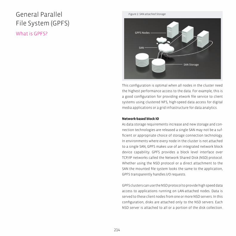
214
This configuration is optimal when all nodes in the cluster need
the highest performance access to the data. For example, this is
a good configuration for providing etwork file service to client
systems using clustered NFS, high-speed data access for digital
media applications or a grid infrastructure for data analytics.
Network-based block IO
As data storage requirements increase and new storage and con-
nection technologies are released a single SAN may not be a suf-
ficient or appropriate choice of storage connection technology.
In environments where every node in the cluster is not attached
to a single SAN, GPFS makes use of an integrated network block
device capability. GPFS provides a block level interface over
TCP/IP networks called the Network Shared Disk (NSD) protocol.
Whether using the NSD protocol or a direct attachment to the
SAN the mounted file system looks the same to the application,
GPFS transparently handles I/O requests.
GPFS clusters can use the NSD protocol to provide high speed data
access to applications running on LAN-attached nodes. Data is
served to these client nodes from one or more NSD servers. In this
configuration, disks are attached only to the NSD servers. Each
NSD server is attached to all or a portion of the disk collection.
Figure 1: SAN attached Storage
GPFS Nodes
SAN
SAN Storage
General Parallel File System (GPFS)
What is GPFS?
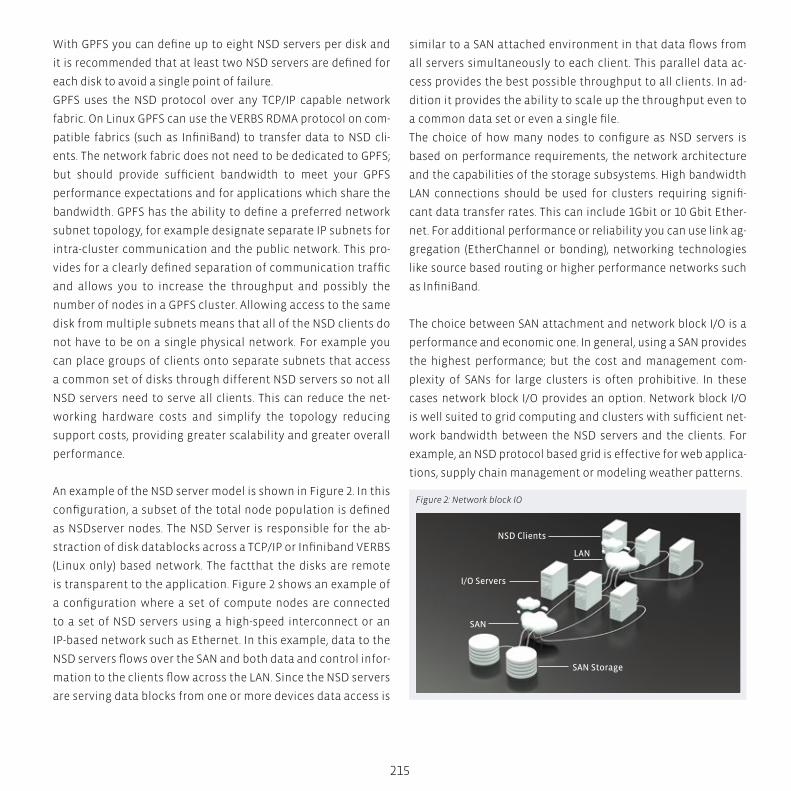
215
With GPFS you can define up to eight NSD servers per disk and
it is recommended that at least two NSD servers are defined for
each disk to avoid a single point of failure.
GPFS uses the NSD protocol over any TCP/IP capable network
fabric. On Linux GPFS can use the VERBS RDMA protocol on com-
patible fabrics (such as InfiniBand) to transfer data to NSD cli-
ents. The network fabric does not need to be dedicated to GPFS;
but should provide sufficient bandwidth to meet your GPFS
performance expectations and for applications which share the
bandwidth. GPFS has the ability to define a preferred network
subnet topology, for example designate separate IP subnets for
intra-cluster communication and the public network. This pro-
vides for a clearly defined separation of communication traffic
and allows you to increase the throughput and possibly the
number of nodes in a GPFS cluster. Allowing access to the same
disk from multiple subnets means that all of the NSD clients do
not have to be on a single physical network. For example you
can place groups of clients onto separate subnets that access
a common set of disks through different NSD servers so not all
NSD servers need to serve all clients. This can reduce the net-
working hardware costs and simplify the topology reducing
support costs, providing greater scalability and greater overall
performance.
An example of the NSD server model is shown in Figure 2. In this
configuration, a subset of the total node population is defined
as NSDserver nodes. The NSD Server is responsible for the ab-
straction of disk datablocks across a TCP/IP or Infiniband VERBS
(Linux only) based network. The factthat the disks are remote
is transparent to the application. Figure 2 shows an example of
a configuration where a set of compute nodes are connected
to a set of NSD servers using a high-speed interconnect or an
IP-based network such as Ethernet. In this example, data to the
NSD servers flows over the SAN and both data and control infor-
mation to the clients flow across the LAN. Since the NSD servers
are serving data blocks from one or more devices data access is
similar to a SAN attached environment in that data flows from
all servers simultaneously to each client. This parallel data ac-
cess provides the best possible throughput to all clients. In ad-
dition it provides the ability to scale up the throughput even to
a common data set or even a single file.
The choice of how many nodes to configure as NSD servers is
based on performance requirements, the network architecture
and the capabilities of the storage subsystems. High bandwidth
LAN connections should be used for clusters requiring signifi-
cant data transfer rates. This can include 1Gbit or 10 Gbit Ether-
net. For additional performance or reliability you can use link ag-
gregation (EtherChannel or bonding), networking technologies
like source based routing or higher performance networks such
as InfiniBand.
The choice between SAN attachment and network block I/O is a
performance and economic one. In general, using a SAN provides
the highest performance; but the cost and management com-
plexity of SANs for large clusters is often prohibitive. In these
cases network block I/O provides an option. Network block I/O
is well suited to grid computing and clusters with sufficient net-
work bandwidth between the NSD servers and the clients. For
example, an NSD protocol based grid is effective for web applica-
tions, supply chain management or modeling weather patterns.
Figure 2: Network block IO
NSD Clients
I/O Servers
LAN
SAN
SAN Storage
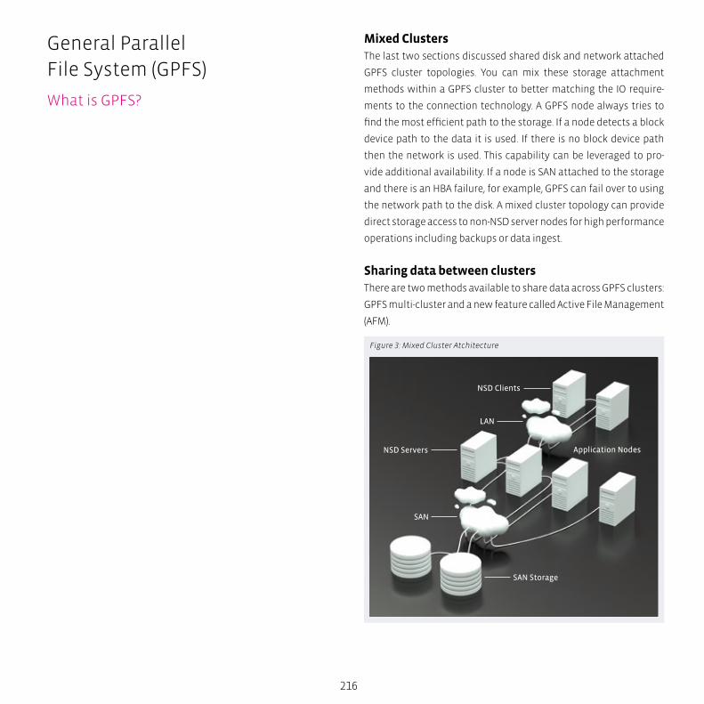
NSD Clients
LAN
SAN
NSD Servers
SAN Storage
Application Nodes
216
Mixed ClustersThe last two sections discussed shared disk and network attached
GPFS cluster topologies. You can mix these storage attachment
methods within a GPFS cluster to better matching the IO require-
ments to the connection technology. A GPFS node always tries to
find the most efficient path to the storage. If a node detects a block
device path to the data it is used. If there is no block device path
then the network is used. This capability can be leveraged to pro-
vide additional availability. If a node is SAN attached to the storage
and there is an HBA failure, for example, GPFS can fail over to using
the network path to the disk. A mixed cluster topology can provide
direct storage access to non-NSD server nodes for high performance
operations including backups or data ingest.
Sharing data between clustersThere are two methods available to share data across GPFS clusters:
GPFS multi-cluster and a new feature called Active File Management
(AFM).
Figure 3: Mixed Cluster Atchitecture
General Parallel File System (GPFS)
What is GPFS?

LANSAN
Cluster A
Cluster C
Cluster B
LAN
217
GPFS Multi-cluster allows you to utilize the native GPFS protocol to
share data across clusters. Using this feature you can allow other
clusters to access one or more of your file systems and you can
mount file systems that belong to other GPFS clusters for which
you have been authorized. A multi-cluster environment allows the
administrator to permit access to specific file systems from another
GPFS cluster. This feature is intended to allow clusters toshare data
at higher performance levels than file sharing technologies like NFS
or CIFS. It is not intended to replace such file sharing technologies
which are optimized for desktop access or for access across unrelia-
ble network links. Multi-cluster capability is useful for sharing across
multiple clusters within a physical location or across locations. Clus-
ters are most often attached using a LAN, but in addition the cluster
connection could include a SAN. Figure 3 illustrates a multi-cluster
configuration with both LAN and mixed LAN and SAN connections.
In Figure 3, Cluster B and Cluster C need to access the data from
Cluster A. Cluster A owns the storage and manages the file system.
It may grant access to file systems which it manages to remote clus-
ters such as Cluster B and Cluster C. In this example, Cluster B and
Cluster C do not have any storage but that is not a requirement. They
could own file systems which may be accessible outside their clus-
ter. Commonly in the case where a cluster does not own storage, the
nodes are grouped into clusters for ease of management.
When the remote clusters need access to the data, they mount the
file system by contacting the owning cluster and passing required
security checks. In Figure 3, Cluster B acesses the data through the
NSD protocol. Cluster C accesses data through an extension of the
SAN. For cluster C access to the data is similar to the nodes in the
host cluster. Control and administrative traffic flows through the IP
network shown in Figure 3 and data access is direct over the SAN.
Both types of configurations are possible and as in Figure 3 can be
mixed as required. Multi-cluster environments are well suited to
sharing data across clusters belonging to different organizations
for collaborative computing , grouping sets of clients for adminis-
trative purposes or implementing a global namespace across sep-
arate locations. A multi-cluster configuration allows you to connect
GPFS clusters within a data center, across campus or across reliable
WAN links. For sharing data between GPFS clusters across less re-
liable WAN links or in cases where you want a copy of the data in
multiple locations you can use a new feature introduced in GPFS 3.5
called Active File Management.
Active File Management (AFM) allows you to create associations be-
tween GPFS clusters. Now the location and flow of file data between
GPFS clusters can be automated. Relationships between GPFS clus-
ters using AFM are defined at the fileset level. A fileset in a file sys-
tem can be created as a “cache” that provides a view to a file system
in another GPFS cluster called the “home.” File data is moved into
a cache fileset on demand. When a file is read the in the cache file-
set the file data is copied from the home into the cache fileset. Data
consistency and file movement into and out of the cache is man-
aged automatically by GPFS.
Cache filesets can be read-only or writeable. Cached data is local-
ly read or written. On read if the data is not in in the “cache” then
GPFS automatically creates a copy of the data. When data is writ-
ten into the cache the write operation completes locally then GPFS
asynchronously pushes the changes back to the home location.
You can define multiple cache filesets for each home data source.
The number of cache relationships for each home is limited only by
Figure 4: Multi-cluster
218
the bandwidth available at the home location. Placing a quota on a
cache fileset causes the data to be cleaned (evicted) out of the cache
automatically based on the space available. If you do not set a quota
a copy of the file data remains in the cache until manually evicted
or deleted.
You can use AFM to create a global namespace within a data center,
across a campus or between data centers located around the world.
AFM is designed to enable efficient data transfers over wide area
network (WAN) connections. When file data is read from home into
cache that transfer can happen in parallel within a node called a
gateway or across multiple gateway nodes.
Using AFM you can now create a truly world-wide global namespace.
Figure 5 is an example of a global namespace built using AFM. In
this example each site owns 1/3 of the namespace, store3 “owns”
/data5 and /data6 for example. The other sites have cache filesets
that point to the home location for the data owned by the other
clusters. In this example store3 /data1-4 cache data owned by the
other two clusters. This provides the same namespace within each
GPFS cluster providing applications one path to a file across the en-
tire organization.
You can achieve this type of global namespace with multi-cluster or
AFM, which method you chose depends on the quality of the WAN
link and the application requirements.
General Parallel File System (GPFS)
What is GPFS?
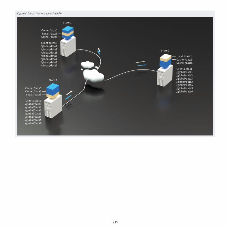
Cache: /data1Local: /data3
Cache: /data5
Local: /data1Cache: /data3 Cache: /data5
Cache: /data1Cache: /data3Local: /data3
Store 1
Store 2
Store 3
Client access:/global/data1/global/data2/global/data3/global/data3/global/data4/global/data5/global/data6
Client access:/global/data1/global/data2/global/data3/global/data3/global/data4/global/data5/global/data6
Client access:/global/data1/global/data2/global/data3/global/data3/global/data4/global/data5/global/data6
219
Figure 5: Global Namespace using AFM
S
N
EW
SESW
NENW
tech BOX
220
General Parallel File System (GPFS)
What’s new in GPFS Version 3.5 What’s new in GPFS Version 3.5For those who are familiar with GPFS 3.4 this section provides a
list of what is new in GPFS Version 3.5.
Active File ManagementWhen GPFS was introduced in 1998 it represented a revolution
in file storage. For the first time a group of servers could share
high performance access to a common set of data over a SAN or
network. The ability to share high performance access to file data
across nodes was the introduction of the global namespace.
Later GPFS introduced the ability to share data across multiple
GPFS clusters. This multi-cluster capability enabled data sharing
between clusters allowing for better access to file data.
This further expanded the reach of the global namespace from
within a cluster to across clusters spanning a data center or a
country. There were still challenges to building a multi-cluster
global namespace. The big challenge is working with unreliable
and high latency network connections between the servers.
Active File Management (AFM) in GPFS addresses the WAN band-
width issues and enables GPFS to create a world-wide global name-
space. AFM ties the global namespace together asynchronous-
ly providing local read and write performance with automated
namespace management. It allows you to create associations be-
tween GPFS clusters and define the location and flow of file data.
High Performance Extended AttributesGPFS has long supported the use of extended attributes, though
in the past they were not commonly used, in part because of

221
performance concerns. In GPFS 3.4, a comprehensive redesign of
the extended attributes support infrastructure was implement-
ed, resulting in significant performance improvements. In GPFS
3.5, extended attributes are accessible by the GPFS policy engine
allowing you to write rules that utilize your custom file attrib-
utes.
Now an application can use standard POSIX interfaces t to man-
age extended attributes and the GPFS policy engine can utilize
these attributes.
Independent FilesetsTo effectively manage a file system with billions of files requires
advanced file management technologies. GPFS 3.5 introduces
a new concept called the independent fileset. An independent
fileset has its own inode space. This means that an independent
fileset can be managed similar to a separate file system but still
allow you to realize the benefits of storage consolidation.
An example of an efficiency introduced with independent file-
sets is improved policy execution performance. If you use an in-
dependent fileset as a predicate in your policy, GPFS only needs
to scan the inode space represented by that fileset, so if you have
1 billion files in your file system and a fileset has an inode space
of 1 million files, the scan only has to look at 1 million inodes. This
instantly makes the policy scan much more efficient. Independ-
ent filesets enable other new fileset features in GPFS 3.5.
Fileset Level Snapshots
Snapshot granularity is now at the fileset level in addition to file
system level snapshots.
Fileset Level Quotas
User and group quotas can be set per fileset
File CloningFile clones are space efficient copies of a file where two instances
of a file share data they have in common and only changed
blocks require additional storage. File cloning is an efficient way
to create a copy of a file, without the overhead of copying all of
the data blocks.
IPv6 SupportIPv6 support in GPFS means that nodes can be defined using mul-
tiple addresses, both IPv4 and IPv6.
GPFS Native RAIDGPFS Native RAID (GNR) brings storage RAID management into
the GPFS NSD server. With GNR GPFS directly manages JBOD
based storage. This feature provides greater availability, flexibili-
ty and performance for a variety of application workloads.
GNR implements a Reed-Solomon based de-clustered RAID tech-
nology that can provide high availability and keep drive failures
from impacting performance by spreading the recovery tasks
over all of the disks. Unlike standard Network Shared Disk (NSD)
data access GNR is tightly integrated with the storage hardware.
For GPFS 3.5 GNR is available on the IBM Power 775 Supercom-
puter platform.
222
ACML (“AMD Core Math Library“)
A software development library released by AMD. This library
provides useful mathematical routines optimized for AMD pro-
cessors. Originally developed in 2002 for use in high-performance
computing (HPC) and scientific computing, ACML allows nearly
optimal use of AMD Opteron processors in compute-intensive
applications. ACML consists of the following main components:
� A full implementation of Level 1, 2 and 3 Basic Linear Algebra
Subprograms (→ BLAS), with optimizations for AMD Opteron
processors.
� A full suite of Linear Algebra (→ LAPACK) routines.
� A comprehensive suite of Fast Fourier transform (FFTs) in sin-
gle-, double-, single-complex and double-complex data types.
� Fast scalar, vector, and array math transcendental library
routines.
� Random Number Generators in both single- and double-pre-
cision.
AMD offers pre-compiled binaries for Linux, Solaris, and Win-
dows available for download. Supported compilers include gfor-
tran, Intel Fortran Compiler, Microsoft Visual Studio, NAG, PathS-
cale, PGI compiler, and Sun Studio.
BLAS (“Basic Linear Algebra Subprograms“)
Routines that provide standard building blocks for performing
basic vector and matrix operations. The Level 1 BLAS perform
scalar, vector and vector-vector operations, the Level 2 BLAS
perform matrix-vector operations, and the Level 3 BLAS per-
form matrix-matrix operations. Because the BLAS are efficient,
portable, and widely available, they are commonly used in the
development of high quality linear algebra software, e.g. → LA-
PACK . Although a model Fortran implementation of the BLAS
in available from netlib in the BLAS library, it is not expected to
perform as well as a specially tuned implementation on most
high-performance computers – on some machines it may give
much worse performance – but it allows users to run → LAPACK
software on machines that do not offer any other implementa-
tion of the BLAS.
Cg (“C for Graphics”)
A high-level shading language developed by Nvidia in close col-
laboration with Microsoft for programming vertex and pixel
shaders. It is very similar to Microsoft’s → HLSL. Cg is based on
the C programming language and although they share the same
syntax, some features of C were modified and new data types
were added to make Cg more suitable for programming graph-
ics processing units. This language is only suitable for GPU pro-
gramming and is not a general programming language. The Cg
compiler outputs DirectX or OpenGL shader programs.
CISC (“complex instruction-set computer”)
A computer instruction set architecture (ISA) in which each in-
struction can execute several low-level operations, such as
a load from memory, an arithmetic operation, and a memory
store, all in a single instruction. The term was retroactively
coined in contrast to reduced instruction set computer (RISC).
The terms RISC and CISC have become less meaningful with the
continued evolution of both CISC and RISC designs and imple-
mentations, with modern processors also decoding and split-
ting more complex instructions into a series of smaller internal
micro-operations that can thereby be executed in a pipelined
fashion, thus achieving high performance on a much larger sub-
set of instructions.
Glossary

223
cluster
Aggregation of several, mostly identical or similar systems to
a group, working in parallel on a problem. Previously known
as Beowulf Clusters, HPC clusters are composed of commodity
hardware, and are scalable in design. The more machines are
added to the cluster, the more performance can in principle be
achieved.
control protocol
Part of the → parallel NFS standard
CUDA driver API
Part of → CUDA
CUDA SDK
Part of → CUDA
CUDA toolkit
Part of → CUDA
CUDA (“Compute Uniform Device Architecture”)
A parallel computing architecture developed by NVIDIA. CUDA
is the computing engine in NVIDIA graphics processing units
or GPUs that is accessible to software developers through in-
dustry standard programming languages. Programmers use
“C for CUDA” (C with NVIDIA extensions), compiled through a
PathScale Open64 C compiler, to code algorithms for execution
on the GPU. CUDA architecture supports a range of computation-
al interfaces including → OpenCL and → DirectCompute. Third
party wrappers are also available for Python, Fortran, Java and
Matlab. CUDA works with all NVIDIA GPUs from the G8X series
onwards, including GeForce, Quadro and the Tesla line. CUDA
provides both a low level API and a higher level API. The initial
CUDA SDK was made public on 15 February 2007, for Microsoft
Windows and Linux. Mac OS X support was later added in ver-
sion 2.0, which supersedes the beta released February 14, 2008.
CUDA is the hardware and software architecture that enables
NVIDIA GPUs to execute programs written with C, C++, Fortran,
→ OpenCL, → DirectCompute, and other languages. A CUDA pro-
gram calls parallel kernels. A kernel executes in parallel across
a set of parallel threads. The programmer or compiler organizes
these threads in thread blocks and grids of thread blocks. The
GPU instantiates a kernel program on a grid of parallel thread
blocks. Each thread within a thread block executes an instance
of the kernel, and has a thread ID within its thread block, pro-
gram counter, registers, per-thread private memory, inputs, and
output results.
Thread
Thread Block
Grid 0
Grid 1
per-Thread PrivateLocal Memory
per-BlockShared Memory
per-Application
ContextGlobal
Memory
...
...
224
A thread block is a set of concurrently executing threads that
can cooperate among themselves through barrier synchroniza-
tion and shared memory. A thread block has a block ID within
its grid. A grid is an array of thread blocks that execute the same
kernel, read inputs from global memory, write results to global
memory, and synchronize between dependent kernel calls. In
the CUDA parallel programming model, each thread has a per-
thread private memory space used for register spills, function
calls, and C automatic array variables. Each thread block has a
per-block shared memory space used for inter-thread communi-
cation, data sharing, and result sharing in parallel algorithms.
Grids of thread blocks share results in global memory space af-
ter kernel-wide global synchronization.
CUDA’s hierarchy of threads maps to a hierarchy of processors
on the GPU; a GPU executes one or more kernel grids; a stream-
ing multiprocessor (SM) executes one or more thread blocks;
and CUDA cores and other execution units in the SM execute
threads. The SM executes threads in groups of 32 threads called
a warp. While programmers can generally ignore warp ex-
ecution for functional correctness and think of programming
one thread, they can greatly improve performance by having
threads in a warp execute the same code path and access mem-
ory in nearby addresses. See the main article “GPU Computing”
for further details.
DirectCompute
An application programming interface (API) that supports gen-
eral-purpose computing on graphics processing units (GPUs)
on Microsoft Windows Vista or Windows 7. DirectCompute is
part of the Microsoft DirectX collection of APIs and was initially
released with the DirectX 11 API but runs on both DirectX 10
and DirectX 11 GPUs. The DirectCompute architecture shares a
range of computational interfaces with → OpenCL and → CUDA.
ETL (“Extract, Transform, Load”)
A process in database usage and especially in data warehousing
that involves:
� Extracting data from outside sources
� Transforming it to fit operational needs (which can include
quality levels)
� Loading it into the end target (database or data warehouse)
The first part of an ETL process involves extracting the data from
the source systems. In many cases this is the most challenging
aspect of ETL, as extracting data correctly will set the stage for
how subsequent processes will go. Most data warehousing proj-
ects consolidate data from different source systems. Each sepa-
rate system may also use a different data organization/format.
Common data source formats are relational databases and flat
files, but may include non-relational database structures such
as Information Management System (IMS) or other data struc-
tures such as Virtual Storage Access Method (VSAM) or Indexed
Sequential Access Method (ISAM), or even fetching from outside
sources such as through web spidering or screen-scraping. The
streaming of the extracted data source and load on-the-fly to
the destination database is another way of performing ETL
when no intermediate data storage is required. In general, the
goal of the extraction phase is to convert the data into a single
format which is appropriate for transformation processing.
An intrinsic part of the extraction involves the parsing of ex-
tracted data, resulting in a check if the data meets an expected
pattern or structure. If not, the data may be rejected entirely or
in part.
Glossary
225
The transform stage applies a series of rules or functions to the
extracted data from the source to derive the data for loading
into the end target. Some data sources will require very little or
even no manipulation of data. In other cases, one or more of the
following transformation types may be required to meet the
business and technical needs of the target database.
The load phase loads the data into the end target, usually the
data warehouse (DW). Depending on the requirements of the
organization, this process varies widely. Some data warehouses
may overwrite existing information with cumulative informa-
tion, frequently updating extract data is done on daily, weekly
or monthly basis. Other DW (or even other parts of the same
DW) may add new data in a historicized form, for example, hour-
ly. To understand this, consider a DW that is required to main-
tain sales records of the last year. Then, the DW will overwrite
any data that is older than a year with newer data. However, the
entry of data for any one year window will be made in a histo-
ricized manner. The timing and scope to replace or append are
strategic design choices dependent on the time available and
the business needs. More complex systems can maintain a his-
tory and audit trail of all changes to the data loaded in the DW.
As the load phase interacts with a database, the constraints de-
fined in the database schema – as well as in triggers activated
upon data load – apply (for example, uniqueness, referential in-
tegrity, mandatory fields), which also contribute to the overall
data quality performance of the ETL process.
FFTW (“Fastest Fourier Transform in the West”)
A software library for computing discrete Fourier transforms
(DFTs), developed by Matteo Frigo and Steven G. Johnson at the
Massachusetts Institute of Technology. FFTW is known as the
fastest free software implementation of the Fast Fourier trans-
form (FFT) algorithm (upheld by regular benchmarks). It can
compute transforms of real and complex-valued arrays of arbi-
trary size and dimension in O(n log n) time.
floating point standard (IEEE 754)
The most widely-used standard for floating-point computa-
tion, and is followed by many hardware (CPU and FPU) and soft-
ware implementations. Many computer languages allow or re-
quire that some or all arithmetic be carried out using IEEE 754
formats and operations. The current version is IEEE 754-2008,
which was published in August 2008; the original IEEE 754-1985
was published in 1985. The standard defines arithmetic formats,
interchange formats, rounding algorithms, operations, and ex-
ception handling. The standard also includes extensive recom-
mendations for advanced exception handling, additional opera-
tions (such as trigonometric functions), expression evaluation,
and for achieving reproducible results. The standard defines
single-precision, double-precision, as well as 128-byte quadru-
ple-precision floating point numbers. In the proposed 754r ver-
sion, the standard also defines the 2-byte half-precision number
format.
FraunhoferFS (FhGFS)
A high-performance parallel file system from the Fraunhofer
Competence Center for High Performance Computing. Built on
scalable multithreaded core components with native → Infini-
Band support, file system nodes can serve → InfiniBand and
Ethernet (or any other TCP-enabled network) connections at the
same time and automatically switch to a redundant connection
path in case any of them fails. One of the most fundamental

226
concepts of FhGFS is the strict avoidance of architectural bottle
necks. Striping file contents across multiple storage servers is
only one part of this concept. Another important aspect is the
distribution of file system metadata (e.g. directory information)
across multiple metadata servers. Large systems and metadata
intensive applications in general can greatly profit from the lat-
ter feature.
FhGFS requires no dedicated file system partition on the servers
– it uses existing partitions, formatted with any of the standard
Linux file systems, e.g. XFS or ext4. For larger networks, it is also
possible to create several distinct FhGFS file system partitions
with different configurations. FhGFS provides a coherent mode,
in which it is guaranteed that changes to a file or directory by
one client are always immediately visible to other clients.
Global Arrays (GA)
A library developed by scientists at Pacific Northwest National
Laboratory for parallel computing. GA provides a friendly API
for shared-memory programming on distributed-memory com-
puters for multidimensional arrays. The GA library is a predeces-
sor to the GAS (global address space) languages currently being
developed for high-performance computing. The GA toolkit has
additional libraries including a Memory Allocator (MA), Aggre-
gate Remote Memory Copy Interface (ARMCI), and functionality
for out-of-core storage of arrays (ChemIO). Although GA was ini-
tially developed to run with TCGMSG, a message passing library
that came before the → MPI standard (Message Passing Inter-
face), it is now fully compatible with → MPI. GA includes simple
matrix computations (matrix-matrix multiplication, LU solve)
and works with → ScaLAPACK. Sparse matrices are available but
the implementation is not optimal yet. GA was developed by Jar-
ek Nieplocha, Robert Harrison and R. J. Littlefield. The ChemIO li-
brary for out-of-core storage was developed by Jarek Nieplocha,
Robert Harrison and Ian Foster. The GA library is incorporated
into many quantum chemistry packages, including NWChem,
MOLPRO, UTChem, MOLCAS, and TURBOMOLE. The GA toolkit is
free software, licensed under a self-made license.
Globus Toolkit
An open source toolkit for building computing grids developed
and provided by the Globus Alliance, currently at version 5.
GMP (“GNU Multiple Precision Arithmetic Library”)
A free library for arbitrary-precision arithmetic, operating on
signed integers, rational numbers, and floating point numbers.
There are no practical limits to the precision except the ones
implied by the available memory in the machine GMP runs on
(operand dimension limit is 231 bits on 32-bit machines and 237
bits on 64-bit machines). GMP has a rich set of functions, and
the functions have a regular interface. The basic interface is
for C but wrappers exist for other languages including C++, C#,
OCaml, Perl, PHP, and Python. In the past, the Kaffe Java virtual
machine used GMP to support Java built-in arbitrary precision
arithmetic. This feature has been removed from recent releases,
causing protests from people who claim that they used Kaffe
solely for the speed benefits afforded by GMP. As a result, GMP
support has been added to GNU Classpath. The main target ap-
plications of GMP are cryptography applications and research,
Internet security applications, and computer algebra systems.
GotoBLAS
Kazushige Goto’s implementation of → BLAS.
Glossary
227
grid (in CUDA architecture)
Part of the → CUDA programming model
GridFTP
An extension of the standard File Transfer Protocol (FTP) for use
with Grid computing. It is defined as part of the → Globus toolkit,
under the organisation of the Global Grid Forum (specifically, by
the GridFTP working group). The aim of GridFTP is to provide a
more reliable and high performance file transfer for Grid com-
puting applications. This is necessary because of the increased
demands of transmitting data in Grid computing – it is frequent-
ly necessary to transmit very large files, and this needs to be
done fast and reliably. GridFTP is the answer to the problem of
incompatibility between storage and access systems. Previous-
ly, each data provider would make their data available in their
own specific way, providing a library of access functions. This
made it difficult to obtain data from multiple sources, requiring
a different access method for each, and thus dividing the total
available data into partitions. GridFTP provides a uniform way
of accessing the data, encompassing functions from all the dif-
ferent modes of access, building on and extending the univer-
sally accepted FTP standard. FTP was chosen as a basis for it
because of its widespread use, and because it has a well defined
architecture for extensions to the protocol (which may be dy-
namically discovered).
Hierarchical Data Format (HDF)
A set of file formats and libraries designed to store and orga-
nize large amounts of numerical data. Originally developed at
the National Center for Supercomputing Applications, it is cur-
rently supported by the non-profit HDF Group, whose mission
is to ensure continued development of HDF5 technologies, and
the continued accessibility of data currently stored in HDF. In
keeping with this goal, the HDF format, libraries and associated
tools are available under a liberal, BSD-like license for general
use. HDF is supported by many commercial and non-commer-
cial software platforms, including Java, MATLAB, IDL, and Py-
thon. The freely available HDF distribution consists of the li-
brary, command-line utilities, test suite source, Java interface,
and the Java-based HDF Viewer (HDFView). There currently exist
two major versions of HDF, HDF4 and HDF5, which differ signifi-
cantly in design and API.
HLSL (“High Level Shader Language“)
The High Level Shader Language or High Level Shading Lan-
guage (HLSL) is a proprietary shading language developed by
Microsoft for use with the Microsoft Direct3D API. It is analo-
gous to the GLSL shading language used with the OpenGL stan-
dard. It is very similar to the NVIDIA Cg shading language, as it
was developed alongside it.
HLSL programs come in three forms, vertex shaders, geometry
shaders, and pixel (or fragment) shaders. A vertex shader is ex-
ecuted for each vertex that is submitted by the application, and
is primarily responsible for transforming the vertex from object
space to view space, generating texture coordinates, and calcu-
lating lighting coefficients such as the vertex’s tangent, binor-
mal and normal vectors. When a group of vertices (normally 3,
to form a triangle) come through the vertex shader, their out-
put position is interpolated to form pixels within its area; this
process is known as rasterisation. Each of these pixels comes
through the pixel shader, whereby the resultant screen colour
is calculated. Optionally, an application using a Direct3D10 in-
228
terface and Direct3D10 hardware may also specify a geometry
shader. This shader takes as its input the three vertices of a tri-
angle and uses this data to generate (or tessellate) additional
triangles, which are each then sent to the rasterizer.
InfiniBand
Switched fabric communications link primarily used in HPC and
enterprise data centers. Its features include high throughput,
low latency, quality of service and failover, and it is designed to
be scalable. The InfiniBand architecture specification defines a
connection between processor nodes and high performance
I/O nodes such as storage devices. Like → PCI Express, and many
other modern interconnects, InfiniBand offers point-to-point
bidirectional serial links intended for the connection of pro-
cessors with high-speed peripherals such as disks. On top of
the point to point capabilities, InfiniBand also offers multicast
operations as well. It supports several signalling rates and, as
with PCI Express, links can be bonded together for additional
throughput.
The SDR serial connection’s signalling rate is 2.5 gigabit per sec-
ond (Gbit/s) in each direction per connection. DDR is 5 Gbit/s
and QDR is 10 Gbit/s. FDR is 14.0625 Gbit/s and EDR is 25.78125
Gbit/s per lane. For SDR, DDR and QDR, links use 8B/10B encod-
ing – every 10 bits sent carry 8 bits of data – making the use-
ful data transmission rate four-fifths the raw rate. Thus single,
double, and quad data rates carry 2, 4, or 8 Gbit/s useful data,
respectively. For FDR and EDR, links use 64B/66B encoding – ev-
ery 66 bits sent carry 64 bits of data.
Implementers can aggregate links in units of 4 or 12, called 4X or
12X. A 12X QDR link therefore carries 120 Gbit/s raw, or 96 Gbit/s
of useful data. As of 2009 most systems use a 4X aggregate, im-
plying a 10 Gbit/s (SDR), 20 Gbit/s (DDR) or 40 Gbit/s (QDR) con-
nection. Larger systems with 12X links are typically used for
cluster and supercomputer interconnects and for inter-switch
connections.
The single data rate switch chips have a latency of 200 nano-
seconds, DDR switch chips have a latency of 140 nanoseconds
and QDR switch chips have a latency of 100 nanoseconds. The
end-to-end latency range ranges from 1.07 microseconds MPI
latency to 1.29 microseconds MPI latency to 2.6 microseconds.
As of 2009 various InfiniBand host channel adapters (HCA) exist
in the market, each with different latency and bandwidth char-
acteristics. InfiniBand also provides RDMA capabilities for low
CPU overhead. The latency for RDMA operations is less than 1
microsecond.
See the main article “InfiniBand” for further description of In-
finiBand features
Intel Integrated Performance Primitives (Intel IPP)
A multi-threaded software library of functions for multimedia
and data processing applications, produced by Intel. The library
supports Intel and compatible processors and is available for
Windows, Linux, and Mac OS X operating systems. It is available
separately or as a part of Intel Parallel Studio. The library takes
advantage of processor features including MMX, SSE, SSE2,
SSE3, SSSE3, SSE4, AES-NI and multicore processors. Intel IPP is
divided into four major processing groups: Signal (with linear ar-
ray or vector data), Image (with 2D arrays for typical color spac-
es), Matrix (with n x m arrays for matrix operations), and Cryp-
tography. Half the entry points are of the matrix type, a third
are of the signal type and the remainder are of the image and
Glossary
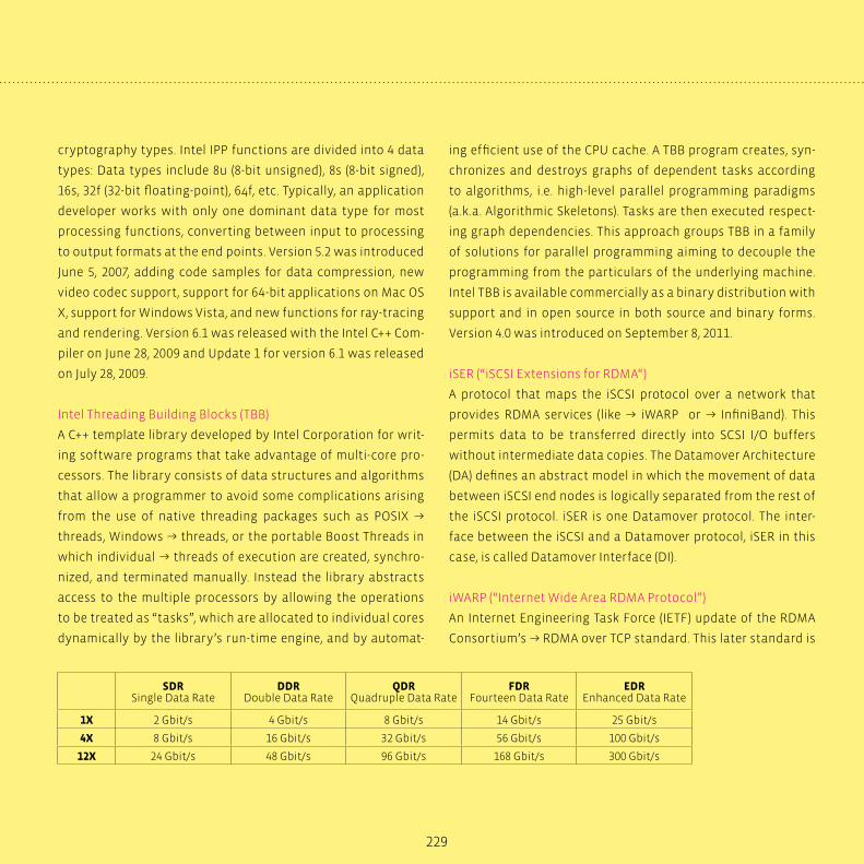
229
cryptography types. Intel IPP functions are divided into 4 data
types: Data types include 8u (8-bit unsigned), 8s (8-bit signed),
16s, 32f (32-bit floating-point), 64f, etc. Typically, an application
developer works with only one dominant data type for most
processing functions, converting between input to processing
to output formats at the end points. Version 5.2 was introduced
June 5, 2007, adding code samples for data compression, new
video codec support, support for 64-bit applications on Mac OS
X, support for Windows Vista, and new functions for ray-tracing
and rendering. Version 6.1 was released with the Intel C++ Com-
piler on June 28, 2009 and Update 1 for version 6.1 was released
on July 28, 2009.
Intel Threading Building Blocks (TBB)
A C++ template library developed by Intel Corporation for writ-
ing software programs that take advantage of multi-core pro-
cessors. The library consists of data structures and algorithms
that allow a programmer to avoid some complications arising
from the use of native threading packages such as POSIX →
threads, Windows → threads, or the portable Boost Threads in
which individual → threads of execution are created, synchro-
nized, and terminated manually. Instead the library abstracts
access to the multiple processors by allowing the operations
to be treated as “tasks”, which are allocated to individual cores
dynamically by the library’s run-time engine, and by automat-
ing efficient use of the CPU cache. A TBB program creates, syn-
chronizes and destroys graphs of dependent tasks according
to algorithms, i.e. high-level parallel programming paradigms
(a.k.a. Algorithmic Skeletons). Tasks are then executed respect-
ing graph dependencies. This approach groups TBB in a family
of solutions for parallel programming aiming to decouple the
programming from the particulars of the underlying machine.
Intel TBB is available commercially as a binary distribution with
support and in open source in both source and binary forms.
Version 4.0 was introduced on September 8, 2011.
iSER (“iSCSI Extensions for RDMA“)
A protocol that maps the iSCSI protocol over a network that
provides RDMA services (like → iWARP or → InfiniBand). This
permits data to be transferred directly into SCSI I/O buffers
without intermediate data copies. The Datamover Architecture
(DA) defines an abstract model in which the movement of data
between iSCSI end nodes is logically separated from the rest of
the iSCSI protocol. iSER is one Datamover protocol. The inter-
face between the iSCSI and a Datamover protocol, iSER in this
case, is called Datamover Interface (DI).
iWARP (“Internet Wide Area RDMA Protocol”)
An Internet Engineering Task Force (IETF) update of the RDMA
Consortium’s → RDMA over TCP standard. This later standard is
SDRSingle Data Rate
DDRDouble Data Rate
QDRQuadruple Data Rate
FDRFourteen Data Rate
EDREnhanced Data Rate
1X 2 Gbit/s 4 Gbit/s 8 Gbit/s 14 Gbit/s 25 Gbit/s
4X 8 Gbit/s 16 Gbit/s 32 Gbit/s 56 Gbit/s 100 Gbit/s
12X 24 Gbit/s 48 Gbit/s 96 Gbit/s 168 Gbit/s 300 Gbit/s
230
zero-copy transmission over legacy TCP. Because a kernel imple-
mentation of the TCP stack is a tremendous bottleneck, a few
vendors now implement TCP in hardware. This additional hard-
ware is known as the TCP offload engine (TOE). TOE itself does
not prevent copying on the receive side, and must be combined
with RDMA hardware for zero-copy results. The main compo-
nent is the Data Direct Protocol (DDP), which permits the ac-
tual zero-copy transmission. The transmission itself is not per-
formed by DDP, but by TCP.
kernel (in CUDA architecture)
Part of the → CUDA programming model
LAM/MPI
A high-quality open-source implementation of the → MPI speci-
fication, including all of MPI-1.2 and much of MPI-2. Superseded
by the → OpenMPI implementation-
LAPACK (“linear algebra package”)
Routines for solving systems of simultaneous linear equations,
least-squares solutions of linear systems of equations, eigen-
value problems, and singular value problems. The original goal
of the LAPACK project was to make the widely used EISPACK and
→ LINPACK libraries run efficiently on shared-memory vector
and parallel processors. LAPACK routines are written so that as
much as possible of the computation is performed by calls to
the → BLAS library. While → LINPACK and EISPACK are based on
the vector operation kernels of the Level 1 BLAS, LAPACK was
designed at the outset to exploit the Level 3 BLAS. Highly effi-
cient machine-specific implementations of the BLAS are avail-
able for many modern high-performance computers. The BLAS
enable LAPACK routines to achieve high performance with por-
table software.
layout
Part of the → parallel NFS standard. Currently three types of
layout exist: file-based, block/volume-based, and object-based,
the latter making use of → object-based storage devices
LINPACK
A collection of Fortran subroutines that analyze and solve linear
equations and linear least-squares problems. LINPACK was de-
signed for supercomputers in use in the 1970s and early 1980s.
LINPACK has been largely superseded by → LAPACK, which has
been designed to run efficiently on shared-memory, vector su-
percomputers. LINPACK makes use of the → BLAS libraries for
performing basic vector and matrix operations.
The LINPACK benchmarks are a measure of a system‘s float-
ing point computing power and measure how fast a computer
solves a dense N by N system of linear equations Ax=b, which is a
common task in engineering. The solution is obtained by Gauss-
ian elimination with partial pivoting, with 2/3•N³ + 2•N² floating
point operations. The result is reported in millions of floating
point operations per second (MFLOP/s, sometimes simply called
MFLOPS).
LNET
Communication protocol in → Lustre
logical object volume (LOV)
A logical entity in → Lustre
Glossary

231
Lustre
An object-based → parallel file system
management server (MGS)
A functional component in → Lustre
MapReduce
A framework for processing highly distributable problems
across huge datasets using a large number of computers
(nodes), collectively referred to as a cluster (if all nodes use the
same hardware) or a grid (if the nodes use different hardware).
Computational processing can occur on data stored either in a
filesystem (unstructured) or in a database (structured).
“Map” step: The master node takes the input, divides it into
smaller sub-problems, and distributes them to worker nodes. A
worker node may do this again in turn, leading to a multi-level
tree structure. The worker node processes the smaller problem,
and passes the answer back to its master node.
“Reduce” step: The master node then collects the answers to all
the sub-problems and combines them in some way to form the
output – the answer to the problem it was originally trying to
solve.
MapReduce allows for distributed processing of the map and
reduction operations. Provided each mapping operation is in-
dependent of the others, all maps can be performed in parallel
– though in practice it is limited by the number of independent
data sources and/or the number of CPUs near each source. Simi-
larly, a set of ‘reducers’ can perform the reduction phase - pro-
vided all outputs of the map operation that share the same key
are presented to the same reducer at the same time. While this
process can often appear inefficient compared to algorithms
that are more sequential, MapReduce can be applied to signifi-
cantly larger datasets than “commodity” servers can handle – a
large server farm can use MapReduce to sort a petabyte of data
in only a few hours. The parallelism also offers some possibility
of recovering from partial failure of servers or storage during
the operation: if one mapper or reducer fails, the work can be
rescheduled – assuming the input data is still available.
metadata server (MDS)
A functional component in → Lustre
metadata target (MDT)
A logical entity in → Lustre
MKL (“Math Kernel Library”)
A library of optimized, math routines for science, engineering,
and financial applications developed by Intel. Core math func-
tions include → BLAS, → LAPACK, → ScaLAPACK, Sparse Solvers,
Fast Fourier Transforms, and Vector Math. The library supports
Intel and compatible processors and is available for Windows,
Linux and Mac OS X operating systems.
MPI, MPI-2 (“message-passing interface”)
A language-independent communications protocol used to
program parallel computers. Both point-to-point and collective
communication are supported. MPI remains the dominant mod-
el used in high-performance computing today. There are two
versions of the standard that are currently popular: version 1.2
(shortly called MPI-1), which emphasizes message passing and
has a static runtime environment, and MPI-2.1 (MPI-2), which in-
cludes new features such as parallel I/O, dynamic process man-
232
agement and remote memory operations. MPI-2 specifies over
500 functions and provides language bindings for ANSI C, ANSI
Fortran (Fortran90), and ANSI C++. Interoperability of objects de-
fined in MPI was also added to allow for easier mixed-language
message passing programming. A side effect of MPI-2 stan-
dardization (completed in 1996) was clarification of the MPI-1
standard, creating the MPI-1.2 level. MPI-2 is mostly a superset
of MPI-1, although some functions have been deprecated. Thus
MPI-1.2 programs still work under MPI implementations com-
pliant with the MPI-2 standard. The MPI Forum reconvened in
2007, to clarify some MPI-2 issues and explore developments for
a possible MPI-3.
MPICH2
A freely available, portable → MPI 2.0 implementation, main-
tained by Argonne National Laboratory
MPP (“massively parallel processing”)
So-called MPP jobs are computer programs with several parts
running on several machines in parallel, often calculating simu-
lation problems. The communication between these parts can
e.g. be realized by the → MPI software interface.
MS-MPI
Microsoft → MPI 2.0 implementation shipped with Microsoft
HPC Pack 2008 SDK, based on and designed for maximum com-
patibility with the → MPICH2 reference implementation.
MVAPICH2
An → MPI 2.0 implementation based on → MPICH2 and devel-
oped by the Department of Computer Science and Engineer-
ing at Ohio State University. It is available under BSD licens-
ing and supports MPI over InfiniBand, 10GigE/iWARP and
RDMAoE.
NetCDF (“Network Common Data Form”)
A set of software libraries and self-describing, machine-inde-
pendent data formats that support the creation, access, and
sharing of array-oriented scientific data. The project homep-
age is hosted by the Unidata program at the University Cor-
poration for Atmospheric Research (UCAR). They are also the
chief source of NetCDF software, standards development,
updates, etc. The format is an open standard. NetCDF Clas-
sic and 64-bit Offset Format are an international standard
of the Open Geospatial Consortium. The project is actively
supported by UCAR. The recently released (2008) version 4.0
greatly enhances the data model by allowing the use of the
→ HDF5 data file format. Version 4.1 (2010) adds support for
C and Fortran client access to specified subsets of remote
data via OPeNDAP. The format was originally based on the
conceptual model of the NASA CDF but has since diverged
and is not compatible with it. It is commonly used in clima-
tology, meteorology and oceanography applications (e.g.,
weather forecasting, climate change) and GIS applications. It
is an input/output format for many GIS applications, and for
general scientific data exchange. The NetCDF C library, and
the libraries based on it (Fortran 77 and Fortran 90, C++, and
all third-party libraries) can, starting with version 4.1.1, read
some data in other data formats. Data in the → HDF5 format
can be read, with some restrictions. Data in the → HDF4 for-
mat can be read by the NetCDF C library if created using the
→ HDF4 Scientific Data (SD) API.
Glossary
233
NetworkDirect
A remote direct memory access (RDMA)-based network interface
implemented in Windows Server 2008 and later. NetworkDirect
uses a more direct path from → MPI applications to networking
hardware, resulting in very fast and efficient networking. See the
main article “Windows HPC Server 2008 R2” for further details.
NFS (Network File System)
A network file system protocol originally developed by Sun Mi-
crosystems in 1984, allowing a user on a client computer to ac-
cess files over a network in a manner similar to how local stor-
age is accessed. NFS, like many other protocols, builds on the
Open Network Computing Remote Procedure Call (ONC RPC)
system. The Network File System is an open standard defined in
RFCs, allowing anyone to implement the protocol.
Sun used version 1 only for in-house experimental purposes.
When the development team added substantial changes to NFS
version 1 and released it outside of Sun, they decided to release
the new version as V2, so that version interoperation and RPC
version fallback could be tested. Version 2 of the protocol (de-
fined in RFC 1094, March 1989) originally operated entirely over
UDP. Its designers meant to keep the protocol stateless, with
locking (for example) implemented outside of the core protocol
Version 3 (RFC 1813, June 1995) added:
� support for 64-bit file sizes and offsets, to handle files larger
than 2 gigabytes (GB)
� support for asynchronous writes on the server, to improve
write performance
� additional file attributes in many replies, to avoid the need
to re-fetch them
� a READDIRPLUS operation, to get file handles and attributes
along with file names when scanning a directory
� assorted other improvements
At the time of introduction of Version 3, vendor support for TCP
as a transport-layer protocol began increasing. While several
vendors had already added support for NFS Version 2 with TCP
as a transport, Sun Microsystems added support for TCP as a
transport for NFS at the same time it added support for Version 3.
Using TCP as a transport made using NFS over a WAN more fea-
sible.
Version 4 (RFC 3010, December 2000; revised in RFC 3530, April
2003), influenced by AFS and CIFS, includes performance im-
provements, mandates strong security, and introduces a state-
ful protocol. Version 4 became the first version developed with
the Internet Engineering Task Force (IETF) after Sun Microsys-
tems handed over the development of the NFS protocols.
NFS version 4 minor version 1 (NFSv 4.1) has been approved by
the IESG and received an RFC number since Jan 2010. The NFSv
4.1 specification aims: to provide protocol support to take ad-
vantage of clustered server deployments including the ability
to provide scalable parallel access to files distributed among
multiple servers. NFSv 4.1 adds the parallel NFS (pNFS) capabil-
ity, which enables data access parallelism. The NFSv 4.1 protocol
defines a method of separating the filesystem meta-data from
the location of the file data; it goes beyond the simple name/
data separation by striping the data amongst a set of data serv-
ers. This is different from the traditional NFS server which holds
the names of files and their data under the single umbrella of
the server.
234
In addition to pNFS, NFSv 4.1 provides sessions, directory del-
egation and notifications, multi-server namespace, access con-
trol lists (ACL/SACL/DACL), retention attributions, and SECIN-
FO_NO_NAME. See the main article “Parallel Filesystems” for
further details.
Current work is being done in preparing a draft for a future ver-
sion 4.2 of the NFS standard, including so-called federated file-
systems, which constitute the NFS counterpart of Microsoft’s
distributed filesystem (DFS).
NUMA (“non-uniform memory access”)
A computer memory design used in multiprocessors, where the
memory access time depends on the memory location relative
to a processor. Under NUMA, a processor can access its own local
memory faster than non-local memory, that is, memory local to
another processor or memory shared between processors.
object storage server (OSS)
A functional component in → Lustre
object storage target (OST)
A logical entity in → Lustre
object-based storage device (OSD)
An intelligent evolution of disk drives that can store and serve
objects rather than simply place data on tracks and sectors.
This task is accomplished by moving low-level storage func-
tions into the storage device and accessing the device through
an object interface. Unlike a traditional block-oriented device
providing access to data organized as an array of unrelated
Glossary
blocks, an object store allows access to data by means of stor-
age objects. A storage object is a virtual entity that groups data
together that has been determined by the user to be logically
related. Space for a storage object is allocated internally by the
OSD itself instead of by a host-based file system. OSDs man-
age all necessary low-level storage, space management, and
security functions. Because there is no host-based metadata
for an object (such as inode information), the only way for an
application to retrieve an object is by using its object identifier
(OID). The SCSI interface was modified and extended by the OSD
Technical Work Group of the Storage Networking Industry Asso-
ciation (SNIA) with varied industry and academic contributors,
resulting in a draft standard to T10 in 2004. This standard was
ratified in September 2004 and became the ANSI T10 SCSI OSD
V1 command set, released as INCITS 400-2004. The SNIA group
continues to work on further extensions to the interface, such
as the ANSI T10 SCSI OSD V2 command set.
OLAP cube (“Online Analytical Processing”)
A set of data, organized in a way that facilitates non-predeter-
mined queries for aggregated information, or in other words,
online analytical processing. OLAP is one of the computer-
based techniques for analyzing business data that are collec-
tively called business intelligence. OLAP cubes can be thought
of as extensions to the two-dimensional array of a spreadsheet.
For example a company might wish to analyze some financial
data by product, by time-period, by city, by type of revenue and
cost, and by comparing actual data with a budget. These addi-
tional methods of analyzing the data are known as dimensions.
Because there can be more than three dimensions in an OLAP
system the term hypercube is sometimes used.
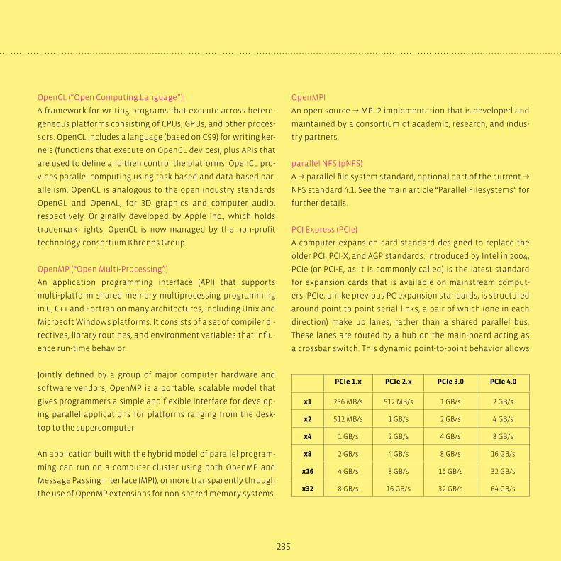
235
OpenCL (“Open Computing Language”)
A framework for writing programs that execute across hetero-
geneous platforms consisting of CPUs, GPUs, and other proces-
sors. OpenCL includes a language (based on C99) for writing ker-
nels (functions that execute on OpenCL devices), plus APIs that
are used to define and then control the platforms. OpenCL pro-
vides parallel computing using task-based and data-based par-
allelism. OpenCL is analogous to the open industry standards
OpenGL and OpenAL, for 3D graphics and computer audio,
respectively. Originally developed by Apple Inc., which holds
trademark rights, OpenCL is now managed by the non-profit
technology consortium Khronos Group.
OpenMP (“Open Multi-Processing”)
An application programming interface (API) that supports
multi-platform shared memory multiprocessing programming
in C, C++ and Fortran on many architectures, including Unix and
Microsoft Windows platforms. It consists of a set of compiler di-
rectives, library routines, and environment variables that influ-
ence run-time behavior.
Jointly defined by a group of major computer hardware and
software vendors, OpenMP is a portable, scalable model that
gives programmers a simple and flexible interface for develop-
ing parallel applications for platforms ranging from the desk-
top to the supercomputer.
An application built with the hybrid model of parallel program-
ming can run on a computer cluster using both OpenMP and
Message Passing Interface (MPI), or more transparently through
the use of OpenMP extensions for non-shared memory systems.
OpenMPI
An open source → MPI-2 implementation that is developed and
maintained by a consortium of academic, research, and indus-
try partners.
parallel NFS (pNFS)
A → parallel file system standard, optional part of the current →
NFS standard 4.1. See the main article “Parallel Filesystems” for
further details.
PCI Express (PCIe)
A computer expansion card standard designed to replace the
older PCI, PCI-X, and AGP standards. Introduced by Intel in 2004,
PCIe (or PCI-E, as it is commonly called) is the latest standard
for expansion cards that is available on mainstream comput-
ers. PCIe, unlike previous PC expansion standards, is structured
around point-to-point serial links, a pair of which (one in each
direction) make up lanes; rather than a shared parallel bus.
These lanes are routed by a hub on the main-board acting as
a crossbar switch. This dynamic point-to-point behavior allows
PCIe 1.x PCIe 2.x PCIe 3.0 PCIe 4.0
x1 256 MB/s 512 MB/s 1 GB/s 2 GB/s
x2 512 MB/s 1 GB/s 2 GB/s 4 GB/s
x4 1 GB/s 2 GB/s 4 GB/s 8 GB/s
x8 2 GB/s 4 GB/s 8 GB/s 16 GB/s
x16 4 GB/s 8 GB/s 16 GB/s 32 GB/s
x32 8 GB/s 16 GB/s 32 GB/s 64 GB/s
236
more than one pair of devices to communicate with each other
at the same time. In contrast, older PC interfaces had all devices
permanently wired to the same bus; therefore, only one device
could send information at a time. This format also allows “chan-
nel grouping”, where multiple lanes are bonded to a single de-
vice pair in order to provide higher bandwidth. The number of
lanes is “negotiated” during power-up or explicitly during op-
eration. By making the lane count flexible a single standard can
provide for the needs of high-bandwidth cards (e.g. graphics
cards, 10 Gigabit Ethernet cards and multiport Gigabit Ethernet
cards) while also being economical for less demanding cards.
Unlike preceding PC expansion interface standards, PCIe is a
network of point-to-point connections. This removes the need
for “arbitrating” the bus or waiting for the bus to be free and
allows for full duplex communications. This means that while
standard PCI-X (133 MHz 64 bit) and PCIe x4 have roughly the
same data transfer rate, PCIe x4 will give better performance
if multiple device pairs are communicating simultaneously or
if communication within a single device pair is bidirectional.
Specifications of the format are maintained and developed by a
group of more than 900 industry-leading companies called the
PCI-SIG (PCI Special Interest Group). In PCIe 1.x, each lane carries
approximately 250 MB/s. PCIe 2.0, released in late 2007, adds a
Gen2-signalling mode, doubling the rate to about 500 MB/s. On
November 18, 2010, the PCI Special Interest Group officially pub-
lishes the finalized PCI Express 3.0 specification to its members
to build devices based on this new version of PCI Express, which
allows for a Gen3-signalling mode at 1 GB/s.
On November 29, 2011, PCI-SIG has annonced to proceed to
PCI Express 4.0 featuring 16 GT/s, still on copper technology.
Glossary
Additionally, active and idle power optimizations are to be in-
vestigated. Final specifications are expected to be released in
2014/15.
PETSc (“Portable, Extensible Toolkit for Scientific Computation”)
A suite of data structures and routines for the scalable (parallel)
solution of scientific applications modeled by partial differential
equations. It employs the → Message Passing Interface (MPI) stan-
dard for all message-passing communication. The current ver-
sion of PETSc is 3.2; released September 8, 2011. PETSc is intended
for use in large-scale application projects, many ongoing compu-
tational science projects are built around the PETSc libraries. Its
careful design allows advanced users to have detailed control
over the solution process. PETSc includes a large suite of parallel
linear and nonlinear equation solvers that are easily used in ap-
plication codes written in C, C++, Fortran and now Python. PETSc
provides many of the mechanisms needed within parallel appli-
cation code, such as simple parallel matrix and vector assembly
routines that allow the overlap of communication and computa-
tion. In addition, PETSc includes support for parallel distributed
arrays useful for finite difference methods.
process
→ thread
PTX (“parallel thread execution”)
Parallel Thread Execution (PTX) is a pseudo-assembly language
used in NVIDIA’s CUDA programming environment. The ‘nvcc’
compiler translates code written in CUDA, a C-like language, into
PTX, and the graphics driver contains a compiler which translates
the PTX into something which can be run on the processing cores.

237
RDMA (“remote direct memory access”)
Allows data to move directly from the memory of one computer
into that of another without involving either one‘s operating
system. This permits high-throughput, low-latency networking,
which is especially useful in massively parallel computer clus-
ters. RDMA relies on a special philosophy in using DMA. RDMA
supports zero-copy networking by enabling the network adapt-
er to transfer data directly to or from application memory, elimi-
nating the need to copy data between application memory and
the data buffers in the operating system. Such transfers require
no work to be done by CPUs, caches, or context switches, and
transfers continue in parallel with other system operations.
When an application performs an RDMA Read or Write request,
the application data is delivered directly to the network, reduc-
ing latency and enabling fast message transfer. Common RDMA
implementations include → InfiniBand, → iSER, and → iWARP.
RISC (“reduced instruction-set computer”)
A CPU design strategy emphasizing the insight that simplified
instructions that “do less“ may still provide for higher perfor-
mance if this simplicity can be utilized to make instructions ex-
ecute very quickly → CISC.
ScaLAPACK (“scalable LAPACK”)
Library including a subset of → LAPACK routines redesigned
for distributed memory MIMD (multiple instruction, multiple
data) parallel computers. It is currently written in a Single-
Program-Multiple-Data style using explicit message passing
for interprocessor communication. ScaLAPACK is designed for
heterogeneous computing and is portable on any computer
that supports → MPI. The fundamental building blocks of the
ScaLAPACK library are distributed memory versions (PBLAS) of
the Level 1, 2 and 3 → BLAS, and a set of Basic Linear Algebra
Communication Subprograms (BLACS) for communication tasks
that arise frequently in parallel linear algebra computations. In
the ScaLAPACK routines, all interprocessor communication oc-
curs within the PBLAS and the BLACS. One of the design goals of
ScaLAPACK was to have the ScaLAPACK routines resemble their
→ LAPACK equivalents as much as possible.
service-oriented architecture (SOA)
An approach to building distributed, loosely coupled applica-
tions in which functions are separated into distinct services
that can be distributed over a network, combined, and reused.
See the main article “Windows HPC Server 2008 R2” for further
details.
single precision/double precision
→ floating point standard
SMP (“shared memory processing”)
So-called SMP jobs are computer programs with several
parts running on the same system and accessing a shared
memory region. A usual implementation of SMP jobs is
→ multi-threaded programs. The communication between the
single threads can e.g. be realized by the → OpenMP software
interface standard, but also in a non-standard way by means of
native UNIX interprocess communication mechanisms.
SMP (“symmetric multiprocessing”)
A multiprocessor or multicore computer architecture where
two or more identical processors or cores can connect to a
238
Glossary
single shared main memory in a completely symmetric way, i.e.
each part of the main memory has the same distance to each of
the cores. Opposite: → NUMA
storage access protocol
Part of the → parallel NFS standard
STREAM
A simple synthetic benchmark program that measures sustain-
able memory bandwidth (in MB/s) and the corresponding com-
putation rate for simple vector kernels.
streaming multiprocessor (SM)
Hardware component within the → Tesla GPU series
subnet manager
Application responsible for configuring the local → InfiniBand
subnet and ensuring its continued operation.
superscalar processors
A superscalar CPU architecture implements a form of parallel-
ism called instruction-level parallelism within a single proces-
sor. It thereby allows faster CPU throughput than would other-
wise be possible at the same clock rate. A superscalar processor
executes more than one instruction during a clock cycle by si-
multaneously dispatching multiple instructions to redundant
functional units on the processor. Each functional unit is not
a separate CPU core but an execution resource within a single
CPU such as an arithmetic logic unit, a bit shifter, or a multiplier.
Tesla
NVIDIA‘s third brand of GPUs, based on high-end GPUs from the
G80 and on. Tesla is NVIDIA‘s first dedicated General Purpose
GPU. Because of the very high computational power (measured
in floating point operations per second or FLOPS) compared to
recent microprocessors, the Tesla products are intended for the
HPC market. The primary function of Tesla products are to aid in
simulations, large scale calculations (especially floating-point
calculations), and image generation for professional and scien-
tific fields, with the use of → CUDA. See the main article “NVIDIA
GPU Computing” for further details.
thread
A thread of execution is a fork of a computer program into two
or more concurrently running tasks. The implementation of
threads and processes differs from one operating system to an-
other, but in most cases, a thread is contained inside a process.
On a single processor, multithreading generally occurs by multi-
tasking: the processor switches between different threads. On
a multiprocessor or multi-core system, the threads or tasks will
generally run at the same time, with each processor or core run-
ning a particular thread or task. Threads are distinguished from
processes in that processes are typically independent, while
threads exist as subsets of a process. Whereas processes have
separate address spaces, threads share their address space,
which makes inter-thread communication much easier than
classical inter-process communication (IPC).
thread (in CUDA architecture)
Part of the → CUDA programming model

239
thread block (in CUDA architecture)
Part of the → CUDA programming model
thread processor array (TPA)
Hardware component within the → Tesla GPU series
10 Gigabit Ethernet
The fastest of the Ethernet standards, first published in 2002
as IEEE Std 802.3ae-2002. It defines a version of Ethernet with
a nominal data rate of 10 Gbit/s, ten times as fast as Gigabit
Ethernet. Over the years several 802.3 standards relating to
10GbE have been published, which later were consolidated
into the IEEE 802.3-2005 standard. IEEE 802.3-2005 and the other
amendments have been consolidated into IEEE Std 802.3-2008.
10 Gigabit Ethernet supports only full duplex links which can
be connected by switches. Half Duplex operation and CSMA/
CD (carrier sense multiple access with collision detect) are not
supported in 10GbE. The 10 Gigabit Ethernet standard encom-
passes a number of different physical layer (PHY) standards. As
of 2008 10 Gigabit Ethernet is still an emerging technology with
only 1 million ports shipped in 2007, and it remains to be seen
which of the PHYs will gain widespread commercial acceptance.
warp (in CUDA architecture)
Part of the → CUDA programming modelOLAP cube

Notes


Notes
Always keep in touch with the latest newsVisit us on the Web!
Here you will find comprehensive information about HPC, IT solutions for the datacenter, services and
high-performance, efficient IT systems.
Subscribe to our technology journals, E-News or the transtec newsletter and always stay up to date.
www.transtec.de/en/hpc
244
transtec Germany
Tel +49 (0) 7121/2678 - 400
www.transtec.de
transtec Switzerland
Tel +41 (0) 44 / 818 47 00
www.transtec.ch
transtec United Kingdom
Tel +44 (0) 1295 / 756 500
www.transtec.co.uk
ttec Netherlands
Tel +31 (0) 24 34 34 210
www.ttec.nl
transtec France
Tel +33 (0) 3.88.55.16.00
www.transtec.fr
Texts and concept:
Layout and design:
Dr. Oliver Tennert | [email protected]
Silke Lerche | [email protected]
Fanny Schwarz | [email protected]
© transtec AG, March 2015
The graphics, diagrams and tables found herein are the intellectual property of transtec AG and may be reproduced or published only with its express permission.
No responsibility will be assumed for inaccuracies or omissions. Other names or logos may be trademarks of their respective owners.