HPC Insightshpc.mil/images/hpcdocs/newsroom/hpcinsights_spring2011.pdfHPCMP – Premier HPC Services...
48
Transcript of HPC Insightshpc.mil/images/hpcdocs/newsroom/hpcinsights_spring2011.pdfHPCMP – Premier HPC Services...

HPC Insights is a semiannual publication of the Department of Defense Super-computing Resource Centers under the auspices of the High Performance Computing Modernization Program.
Publication Team
AFRL DSRC, Wright-Patterson Air Force Base, OH Joan HenleyChuck Abruzzino
ARL DSRC, Aberdeen ProvingGround, MDDebbie ThompsonBrian Simmonds
ERDC DSRC, Vicksburg, MSRose J. Dykes
MHPCC DSRC, Maui, HIBetty Duncan
Navy DSRC, Stennis SpaceCenter, MSChristine CuicchiLynn Yott
HPCMPO, Lorton, VADeborah SchwartzDenise O’DonnellLeah Glick
MANAGING EDITORRose J. Dykes, ERDC DSRC
DESIGN/LAYOUTBetty Watson, ACE-IT
COVER DESIGNChandra “Pat” Caldwell, ACE-IT
The contents of this publication are not to be used for adver t is ing, publication, or promotional purposes. Citation of trade names does not constitute an official endorsement or approval of the use of such commercial products. Any opinions, findings, conclusions, or recommendations expressed in this publication are those of the author(s) and do not necessarily reflect the views of the DoD.
Approved for Public Release; Distribution Is Unlimited.
ContentsHPCMP – Premier HPC Services for the DoD
by HPC Centers Project Manager – Brad Comes ........................1
DoD Supercomputing Resource CentersAFRL DSRCFrom the Director’s Desk – Frank Witzeman ..............................................2Introducing Raptor at the AFRL ...................................................................3
ARL DSRCFrom the Acting Director’s Desk – Thomas Kendall ....................................4
ERDC DSRCFrom the Director’s Desk – Dr. Robert S. Maier ......................................... 5HPCMP Open System Computing Component Transitions
from ARSC to ERDC ..............................................................................6MHPCC DSRCFrom the Director’s Desk – David Morton ...................................................7Green Technology: Photovoltaics on Maui ..................................................8
NAVY DSRCFrom the Director’s Desk – Tom Dunn ........................................................9
DAACEnSight HPC Job Launching .....................................................................10Secure Remote Visualization Services ..................................................... 11
Helping the HPC UserA User-Friendly HPC Web Portal for MATLAB® and Microsoft®
Windows® Applications ........................................................................12Special Considerations for Application Run Scheduling............................14HPCMP Enhanced User Environment ......................................................16Kestrel: A High-Fidelity, Full-Vehicle, Multiphysics Analysis Tool
for Fixed-Wing Aircraft ..........................................................................18Improve Job Throughput in One Easy Step ..............................................19Lecture Series on Large-Scale Computing ...............................................20Using CSE for Software Development ......................................................21Rotorcraft Aeromechanics Modeling and
Simulation – HELIOS Testing ...............................................................25Checking Status of Shared-Application Licenses......................................26Programming GPUs Using Python PyCUDA .............................................28Everything You Ever Wanted to Know About the HPCMP TI-11/12
Benchmarking Process but Were Afraid to Ask ....................................32HPCMP Sustained Systems Performance Test: What It Is
and How It Works .................................................................................41SC10 Wrap-Up ..........................................................................................43
AnnouncementsSC11 ..........................................................................................................45
HPCMP – Premier HPC Services for the DoDBy Brad Comes, HPC Centers Project Manager, Department of Defense High Performance Computing Modernization Program Office, Lorton, Virginia
HPC Insights, Spring 2011 1
The High Performance Computing Modernization Program (HPCMP) continues to live up to “modernization” in its name. We deployed three large high performance computing (HPC) systems in 2010 that exceeded the collective capability of all 16 systems operational in 2009. We currently have 14 systems consisting of 169,280 compute cores and 430 terabytes of memory with a collective peak FLOPS (floating point opera-tions per second) rating of 1.785 petaflops. Our largest system is located at the Air Force Research Laboratory (AFRL) DoD Supercomputing Resource Center (DSRC) and consists of 43,712 compute cores and 87.4 terabytes of memory. Earlier this year, users tested the system by running DoD applications that consumed over 20,000 cores per job.
We recently deployed and continue to mature a new service delivery mechanism known as Advance Reservation Service (ARS). ARS allows users to reserve a specific time, dura-tion, and number of compute cores. Single reservations can be used by multiple users (authorized project teams), can be made 24 hours or more prior to runtime, and can have dura-tion of 1 week. Eight-hour reservations can be made upon demand providing the resources are available. ARS is avail-able on all DSRC systems.
Most recently we’ve created yet another service delivery mechanism. It is called Dedicated Service Partitions (DSPs) and consists of partitions of HPC systems dedicated to spe-cific projects—similar to owning your own cluster. DSPs are awarded via a two- to three-page justification and can have duration of between 1 and 12 months. Based upon the fact that Service/Agency or Challenge allocations must address the compute hours associated with the duration of the parti-tion, we speculate that partitions will not exceed 2000 cores each, but exceptions will be considered.
You may have heard about the HPC Enhanced User Experience (HEUE) project. It started out as an initiative to provide the user community with better tools and capabili-ties to manage their stored data and has evolved into a new way to interact with a DSRC. The initiative adds an interac-tive utility server to each DSRC’s infrastructure supporting a 30-day temporary file storage capability, remote HPC job management capabilities, and remote data analysis services. In support of the data analysis services (scientific visualiza-tion), some of the utility server’s nodes include GPGPUs; but we also expect to see users leveraging these for small-scale experiments with attached processors. Additionally, a new terminal emulator called VNC (we’ve implemented PKIVNC) will be available via the utility servers. We’ve tested PKIVNC and confirmed that it provides reasonable refresh rates for graphics on standard network connections. We view this as a cornerstone capability for new interactive services. Lastly, HEUE includes a database management system that stores metadata related to the files users have
Brad ComesHPC Centers Project Manager
placed in archive. The system will automatically attach some data elements to files, while the user can attach their own data elements. All data elements (metadata) are available for query by the user.
Another project we’re currently pursuing is Portal Services, which can be best described as web-based front-ends to HPC. The Army Research Laboratory (ARL) DSRC originally explored this space and laid the foundation for our commitment to continue to pursue this service for our user community. We recently designated the Maui High Performance Computing Center (MHPCC) DSRC as the lead center to provide portal services. MHPCC has inher-ited a project ARL initiated that will deliver Matlab to the desktop via HPC systems. You should see this capability before the end of the fiscal year. Other portal services on the horizon include interfaces for products from the CREATE program. CREATE is a software development program within the HPCMP focused on providing next-generation physics-based codes for air vehicle, ship, and antenna de-sign. In general, portal services can be developed for any workflow and analysis process that is repeatable. Keep an eye on the MHPCC DSRC for additional details related to portal services.
Last but certainly not least, the HPCMP has been moved to the Army for fiscal year 2012 and beyond. The Army has clearly indicated that they intend to continue to run the Program as a joint services/agencies program. They have designated the Engineer Research and Development Center (ERDC) as the organization to lead the effort. The Program will reside within ERDC’s Information Technology Laboratory, the same organization that currently hosts the ERDC DSRC. Change is always a distraction, but this change has additional challenges. The FY12 and out-budget profile for the Program has been adjusted downward. Our priority is to facilitate a smooth transition to the Army and address challenges associated with the new budget profile while continuing to provide the DoD with premier HPC services.
AFRL DSRC
Air Force Research Laboratory DoD Supercomputing Resource Center, Wright-Patterson Air Force Base, OhioFrom the Director’s Desk – Frank Witzeman
2 HPC Insights, Spring 2011
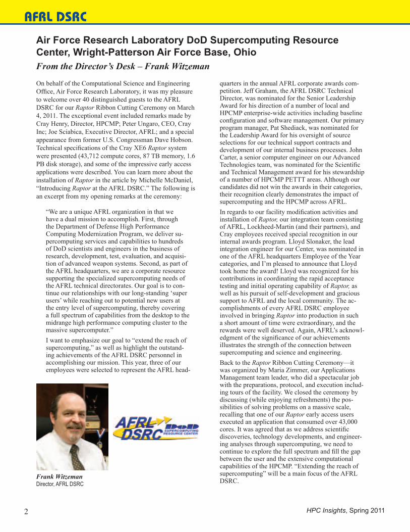
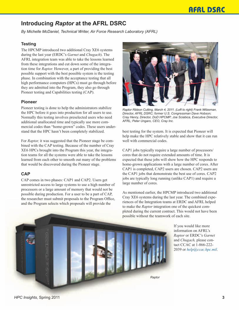
On behalf of the Computational Science and Engineering Office, Air Force Research Laboratory, it was my pleasure to welcome over 40 distinguished guests to the AFRL DSRC for our Raptor Ribbon Cutting Ceremony on March 4, 2011. The exceptional event included remarks made by Cray Henry, Director, HPCMP; Peter Ungaro, CEO, Cray Inc; Joe Sciabica, Executive Director, AFRL; and a special appearance from former U.S. Congressman Dave Hobson. Technical specifications of the Cray XE6 Raptor system were presented (43,712 compute cores, 87 TB memory, 1.6 PB disk storage), and some of the impressive early access applications were described. You can learn more about the installation of Raptor in the article by Michelle McDaniel, “Introducing Raptor at the AFRL DSRC.” The following is an excerpt from my opening remarks at the ceremony:
“We are a unique AFRL organization in that we have a dual mission to accomplish. First, through the Department of Defense High Performance Computing Modernization Program, we deliver su-percomputing services and capabilities to hundreds of DoD scientists and engineers in the business of research, development, test, evaluation, and acquisi-tion of advanced weapon systems. Second, as part of the AFRL headquarters, we are a corporate resource supporting the specialized supercomputing needs of the AFRL technical directorates. Our goal is to con-tinue our relationships with our long-standing ‘super users’ while reaching out to potential new users at the entry level of supercomputing, thereby covering a full spectrum of capabilities from the desktop to the midrange high performance computing cluster to the massive supercomputer.”I want to emphasize our goal to “extend the reach of supercomputing,” as well as highlight the outstand-ing achievements of the AFRL DSRC personnel in accomplishing our mission. This year, three of our employees were selected to represent the AFRL head-
quarters in the annual AFRL corporate awards com-petition. Jeff Graham, the AFRL DSRC Technical Director, was nominated for the Senior Leadership Award for his direction of a number of local and HPCMP enterprise-wide activities including baseline configuration and software management. Our primary program manager, Pat Shediack, was nominated for the Leadership Award for his oversight of source selections for our technical support contracts and development of our internal business processes. John Carter, a senior computer engineer on our Advanced Technologies team, was nominated for the Scientific and Technical Management award for his stewardship of a number of HPCMP PETTT areas. Although our candidates did not win the awards in their categories, their recognition clearly demonstrates the impact of supercomputing and the HPCMP across AFRL.In regards to our facility modification activities and installation of Raptor, our integration team consisting of AFRL, Lockheed-Martin (and their partners), and Cray employees received special recognition in our internal awards program. Lloyd Slonaker, the lead integration engineer for our Center, was nominated in one of the AFRL headquarters Employee of the Year categories, and I’m pleased to announce that Lloyd took home the award! Lloyd was recognized for his contributions in coordinating the rapid acceptance testing and initial operating capability of Raptor, as well as his pursuit of self-development and gracious support to AFRL and the local community. The ac-complishments of every AFRL DSRC employee involved in bringing Raptor into production in such a short amount of time were extraordinary, and the rewards were well deserved. Again, AFRL’s acknowl-edgment of the significance of our achievements illustrates the strength of the connection between supercomputing and science and engineering.Back to the Raptor Ribbon Cutting Ceremony—it was organized by Maria Zimmer, our Applications Management team leader, who did a spectacular job with the preparations, protocol, and execution includ-ing tours of the facility. We closed the ceremony by discussing (while enjoying refreshments) the pos-sibilities of solving problems on a massive scale, recalling that one of our Raptor early access users executed an application that consumed over 43,000 cores. It was agreed that as we address scientific discoveries, technology developments, and engineer-ing analyses through supercomputing, we need to continue to explore the full spectrum and fill the gap between the user and the extensive computational capabilities of the HPCMP. “Extending the reach of supercomputing” will be a main focus of the AFRL DSRC.Frank Witzeman
Director, AFRL DSRC
HPC Insights, Spring 2011 3
AFRL DSRC
TestingThe HPCMP introduced two additional Cray XE6 systems during the last year (ERDC’s Garnet and Chugach). The AFRL integration team was able to take the lessons learned from these integrations and cut down some of the integra-tion time for Raptor. However, a part of providing the best possible support with the best possible system is the testing phase. In combination with the acceptance testing that all high performance computers (HPCs) must go through before they are admitted into the Program, they also go through Pioneer testing and Capabilities testing (CAP).
PioneerPioneer testing is done to help the administrators stabilize the HPC before it goes into production for all users to use. Normally this testing involves preselected users who need additional unallocated time and typically use more com-mercial codes than “home-grown” codes. These users under-stand that the HPC hasn’t been completely stabilized.
For Raptor, it was suggested that the Pioneer stage be com-bined with the CAP testing. Because of the number of Cray XE6 HPCs brought into the Program this year, the integra-tion teams for all the systems were able to take the lessons learned from each other to smooth out many of the problems that would be discovered during the Pioneer stage.
CAPCAP comes in two phases: CAP1 and CAP2. Users get unrestricted access to large systems to use a high number of processors or a large amount of memory that would not be possible during production. For a user to be a part of CAP, the researcher must submit proposals to the Program Office, and the Program selects which proposals will provide the
Introducing Raptor at the AFRL DSRCBy Michelle McDaniel, Technical Writer, Air Force Research Laboratory (AFRL)
best testing for the system. It is expected that Pioneer will help make the HPC relatively stable and show that it can run well with commercial codes.
CAP1 jobs typically require a large number of processors/cores that do not require extended amounts of time. It is expected that these jobs will show how the HPC responds to home-grown applications with a large number of cores. After CAP1 is completed, CAP2 users are chosen. CAP2 users are the CAP1 jobs that demonstrate the best use of cores. CAP2 jobs are typically long running (unlike CAP1) and require a large number of cores.
As mentioned earlier, the HPCMP introduced two additional Cray XE6 systems during the last year. The combined expe-riences of the Integration teams at ERDC and AFRL helped to make the Raptor integration one of the quickest com-pleted during the current contract. This would not have been possible without the teamwork of each site.
Raptor Ribbon Cutting, March 4, 2011. (Left to right) Frank Witzeman, Director, AFRL DSRC; former U.S. Congressman Dave Hobson; Cray Henry, Director, DoD HPCMP; Joe Sciabica, Executive Director, AFRL; Peter Ungaro, CEO, Cray Inc.
If you would like more information on AFRL’s Raptor or ERDC’s Garnet and Chugach, please con-tact CCAC at 1-866-222-2039 or [email protected].
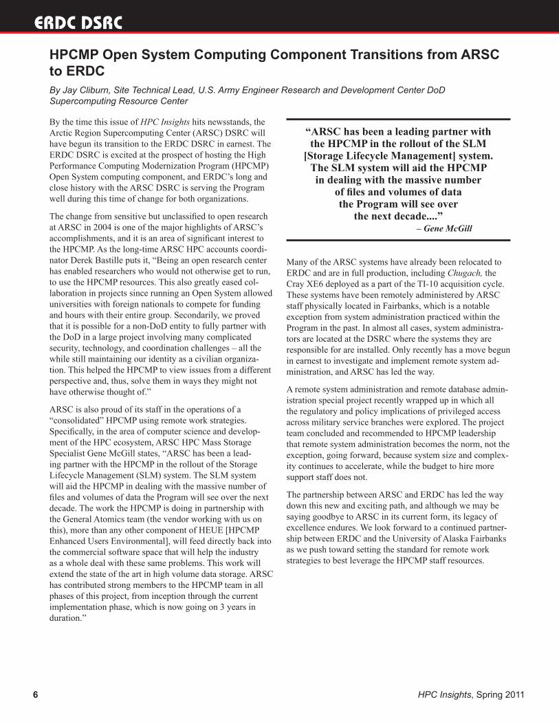
Raptor
Army Research Laboratory DoD Supercomputing Resource Center, Aberdeen Proving Ground, MarylandFrom the Acting Director’s Desk – Thomas Kendall
ARL DSRC
4 HPC Insights, Spring 2011
In the Fall 2010 edition of HPC Insights, Charlie Nietubicz, who had served as the Director of the ARL DSRC since its inception, wrote his last article before retiring and moving on to the next phase of his life after 39 years of service to the Army. Now, I’d like to introduce myself to those of you who I haven’t had the good fortune to meet yet. Like Charlie, I came to the HPCMP as a user. I began my career at the Ballistic Research Laboratory (BRL), one of ARL’s prede-cessor organizations, as a cooperative education student in 1986, just as the Laboratory’s first Cray was being installed. After completing my undergraduate degree, I went on to the University of Illinois, where I completed a master’s degree in theoretical and applied mechanics, and utilized the Crays at the National Center for Supercomputing Applications, as well as those at BRL, to study the dynamics of turbulent channel flow. When I came back to BRL after completing my degree, I moved into the organization within the labora-tory that has evolved into the Computational and Information Sciences Directorate, which hosts the ARL DSRC. Just after the formation of ARL from its component laboratories, I worked on a small team to explore parallel computing, le-veraging systems within the lab, as well as the Connection Machines at the Army High Performance Computing Research Center, and the HPCMP’s early access systems, including the SGI Power Challenge Array and The Kendall Square Research KSR-1 hosted by ARL, the Intel Paragon hosted by Aeronautical Systems Command, and the IBM SP-2 hosted by the Maui High Performance Computing Center.
These experiences as a user of HPC technologies further whet my appetite for leading-edge technology, and I was asked to assist with the initial Major Shared Resource Center application benchmarking effort and jumped at the chance. Later, I became Deputy Director for Technology and Operations within the Center and took on the responsibility to integrate new systems and transition them to production.
I have had the pleasure of working with an outstanding team both within ARL and the HPCMP and now have the chal-lenge of leading the ARL DSRC into and through its next set of challenges and opportunities.
I am excited about being involved in ARL’s role as the Executive Agent for the HPCMP Enhanced User Environment (EUE). We are moving out on the planning and implementation of the long-awaited storage lifecycle management, utility server, and centerwide file system ca-pabilities. Individually, these are important additions to the computational capabilities the DSRCs have offered for the past 15 years. Collectively, they are the first major revolu-tion in the architecture of the DSRCs since their inception. Their implementation is motivated by the recognition that the DoD’s most valuable supercomputing resource is its scientists and engineers and not its HPC systems. EUE will enable new ways to exploit HPC that help to do away with the paradigm that people should wait for computers and fun-damentally improve the process of turning an idea into data and hence to information. Today’s center architecture is chal-lenged by this workflow, particularly in the analysis step, to turn the vast amounts of data output from three-dimensional, time-dependent models into information relevant to improv-ing the design of the weapons system of tomorrow.
While preparing for EUE’s transition to operations is a tre-mendously large and complicated task, it is by no means the only major effort ongoing within the Center. Our facilities team is working to expand our facilities’ capacity and resil-ience. Our systems administration and applications teams are working to improve the resiliency and effectiveness of the Harold and TOW systems. Recently, both Harold and TOW received major updates to their Linux operating system and Lustre file system software. Finally, the team responsible for development and sustainment of the Advance Reservation Service has been working to add functionality requested by customers.
The road ahead is certain to be filled with accomplishments and challenges. I am looking forward to working through each of these in the pursuit of providing the essential re-sources and services that the ARL DSRC customer community requires.
Thomas KendallActing Director, ARL DSRC
HPC Insights, Spring 2011 5
ERDC DSRC
Dr. Robert S. MaierDirector, ERDC DSRC
U.S. Army Engineer Research and Development Center DoD Supercomputing Resource Center, Vicksburg, MississippiFrom the Director’s Desk – Dr. Robert S. Maier“The Exascale Roadmap takes us from the petascale science of today to tomorrow’s exascale science, where the nation can tackle some of its most important problems in energy, climate change, health, and security.” (http://www.scidacre-view.org/1001/html/hardware.html)
The exascale roadmap leads to a computer one thousand times more powerful than ORNL’s Jaguar by 2020 that draws 20 MW compared with Jaguar’s 2.2 MW. Computing power will grow 2× per year, and computing power per watt will grow 1.6× per year. If the cost is comparable, in today’s dollars, with Jaguar’s $200M book value, computing power per dollar will grow 2× per year.
DoD supercomputing has followed the same technology trends that drove the petascale roadmap, leading to Jaguar. In fact, the HPCMP has increased DoD supercomputing capability every year with procurement budgets that have grown hardly at all and projects further growth in computing capability on flat budgets.
A group of us recently made some unofficial projections of power requirements for DoD supercomputing systems. We wanted to know how far DoD might follow the exascale road-map on a fixed budget before power costs restrict our ability to grow. We assumed a budget of $100M every 2 years to cover new hardware, power, and new power infrastructure. In the 2013-2014 budget cycle, projected power and infrastruc-ture costs approach 50 percent of the budget, and they domi-nate in 2015-2016. By the 2025-26 budget cycle, less than 10 percent of the budget is projected available for new computer hardware; the balance is needed for power and infrastructure. These projections assume that computing power per watt will improve 1.6× per year, which is faster than recent trends. Yet even with such an optimistic assumption, we still projected that power will consume the budget by 2025. In the simple mathematics of our projection, the trend in computing power per watt is the growth-rate limiting factor.
The exascale roadmap assumes a variety of hardware and software energy-efficiency improvements, and these as-sumptions are built into the 1.6× growth rate in computing power per watt. For example, GPU accelerator technology is assumed in the roadmap. So our projections also assume that we will embrace new software development paradigms.
Some technology goals are not key milestones in the exas-cale roadmap, such as the codesign of computers and facili-ties and infrastructure. An example of such a goal would be to operate systems at much higher temperatures, decreasing cooling costs by 90 percent and eliminating major cooling infrastructure. If ambient air temperatures were sufficient to provide a low-temperature reservoir for cooling high-temperature racks, the need for chillers and CRAH units
would be eliminated, along with a significant amount of power consumption.
Another goal would be to reclaim 10 percent of waste heat from system cabinets as useful energy. Waste heat below 450 degrees is classified as low grade, difficult to reclaim. The limiting Carnot efficiency of waste heat produced by even high-temperature racks would be substantially less than 10 percent, so this is a challenging area for research. But when you consider that our HPC Centers are intended to operate around the clock, the idea of integrating waste heat reclama-tion infrastructure with the HPC Center seems attractive.
One of the challenges to codesign is the technical background of Center staff. It requires some industrial engineering or power systems training and experience. Without that back-ground, it’s hard to work with computer manufacturers and facilities staff to design experiments and demonstrations. My awareness is due to the outstanding staff at ERDC, like Greg Rottman, Mickey Robertson, and Paula Lindsey, who have significant experience in HPC systems and facilities design. Greg received an ERDC award last year for getting our HPC infrastructure up and running in record time. Mickey spent a number of years as a general manager and executive with Cooper Lighting Industries, including designing transformers. Paula has managed infrastructure for systems ranging from Sun servers to ORNL’s Jaguar. Not every Center has this level of senior staff experience. But one gets the sense this might be changing. SC11 includes an interest area called State of the Practice that will consider “… provisioning, using and improving the critical systems and services in high perfor-mance computing, networking, and storage … . The challeng-es include improving performance at scale, large-scale system management and deployment, highly parallel storage, and energy efficiency.” This should help to elevate the importance of codesign in our Centers. The scope of high performance computing is expanding to include power efficiency as a key area of expertise.
ERDC DSRC
6 HPC Insights, Spring 2011
By the time this issue of HPC Insights hits newsstands, the Arctic Region Supercomputing Center (ARSC) DSRC will have begun its transition to the ERDC DSRC in earnest. The ERDC DSRC is excited at the prospect of hosting the High Performance Computing Modernization Program (HPCMP) Open System computing component, and ERDC’s long and close history with the ARSC DSRC is serving the Program well during this time of change for both organizations.
The change from sensitive but unclassified to open research at ARSC in 2004 is one of the major highlights of ARSC’s accomplishments, and it is an area of significant interest to the HPCMP. As the long-time ARSC HPC accounts coordi-nator Derek Bastille puts it, “Being an open research center has enabled researchers who would not otherwise get to run, to use the HPCMP resources. This also greatly eased col-laboration in projects since running an Open System allowed universities with foreign nationals to compete for funding and hours with their entire group. Secondarily, we proved that it is possible for a non-DoD entity to fully partner with the DoD in a large project involving many complicated security, technology, and coordination challenges – all the while still maintaining our identity as a civilian organiza-tion. This helped the HPCMP to view issues from a different perspective and, thus, solve them in ways they might not have otherwise thought of.”
ARSC is also proud of its staff in the operations of a “consolidated” HPCMP using remote work strategies. Specifically, in the area of computer science and develop-ment of the HPC ecosystem, ARSC HPC Mass Storage Specialist Gene McGill states, “ARSC has been a lead-ing partner with the HPCMP in the rollout of the Storage Lifecycle Management (SLM) system. The SLM system will aid the HPCMP in dealing with the massive number of files and volumes of data the Program will see over the next decade. The work the HPCMP is doing in partnership with the General Atomics team (the vendor working with us on this), more than any other component of HEUE [HPCMP Enhanced Users Environmental], will feed directly back into the commercial software space that will help the industry as a whole deal with these same problems. This work will extend the state of the art in high volume data storage. ARSC has contributed strong members to the HPCMP team in all phases of this project, from inception through the current implementation phase, which is now going on 3 years in duration.”
HPCMP Open System Computing Component Transitions from ARSC to ERDCBy Jay Cliburn, Site Technical Lead, U.S. Army Engineer Research and Development Center DoD Supercomputing Resource Center
Many of the ARSC systems have already been relocated to ERDC and are in full production, including Chugach, the Cray XE6 deployed as a part of the TI-10 acquisition cycle. These systems have been remotely administered by ARSC staff physically located in Fairbanks, which is a notable exception from system administration practiced within the Program in the past. In almost all cases, system administra-tors are located at the DSRC where the systems they are responsible for are installed. Only recently has a move begun in earnest to investigate and implement remote system ad-ministration, and ARSC has led the way.
A remote system administration and remote database admin-istration special project recently wrapped up in which all the regulatory and policy implications of privileged access across military service branches were explored. The project team concluded and recommended to HPCMP leadership that remote system administration becomes the norm, not the exception, going forward, because system size and complex-ity continues to accelerate, while the budget to hire more support staff does not.
The partnership between ARSC and ERDC has led the way down this new and exciting path, and although we may be saying goodbye to ARSC in its current form, its legacy of excellence endures. We look forward to a continued partner-ship between ERDC and the University of Alaska Fairbanks as we push toward setting the standard for remote work strategies to best leverage the HPCMP staff resources.
– Gene McGill
“ARSC has been a leading partner with the HPCMP in the rollout of the SLM
[Storage Lifecycle Management] system. The SLM system will aid the HPCMP in dealing with the massive number
of files and volumes of data the Program will see over
the next decade....”

Maui High Performance Computing Center DoD Supercomputing Resource Center, Maui, HawaiiFrom the Director’s Desk – David Morton
MHPCC DSRC
David MortonDirector, MHPCC DSRC
HPC Insights, Spring 2011 7
The HPCMP has been evolving rapidly toward a much more user-centric organization over the past few years. The Advanced Reservation System (ARS) was announced and made available at the 2010 Users Group Conference, and there are several initiatives including utility servers, the Portal initiative, and center-wide file systems that are being made available in the 2011 time frame. The Program realizes that the current and future user base demands easily accessed high performance computing (HPC) resources that are avail-able to the user in a spectrum of accessibility options ranging from interactive to large-scale batch environments. MHPCC is proud to play a role in expanding these user options.
During the past year, the MHPCC DSRC has been actively engaged in assisting the CREATE development team in test-ing their upcoming code releases. These efforts can be a ma-jor enabler for the U.S. to sustain its competitive advantage in military platform development. As part of the CREATE program, the MHPCC DSRC hosted beta testing of the Kestrel (high-fidelity, full-vehicle, multiphysics analysis tool for fixed-wing aircraft) and HELIOS (high-fidelity, full-vehicle, multiphysics analysis tool for rotary-wing aircraft). Kestrel testing ran from July-September 2010. Through the ARS, 2080 cores on the Mana system were reserved for the 6-week testing period followed by a 4-week early access period. HELIOS testing ran from November-January 2011. Through the ARS, 2000 cores on the Mana system were reserved for this 6-week testing period followed by a 4-week early access period. Early results of the testing can be found in upcoming articles.
While utilizing the ARS system, these long-running, large-testing efforts required custom reservations and queue structures. The success of this effort led to a similar request for a dedicated “virtual” cluster at the AFRL DSRC. In this instance, a software development team has 512 cores from the new Cray XE6 system, Raptor, dedicated to them dur-ing the appropriate time frames. As you can imagine, these innovative types of accessibility options have generated considerable interest in the user community.
One other innovative user accessibility option was recently exercised at MHPCC. This Center has long allowed cus-tom large-system reservations immediately before or after planned system outage. The rationalization is that all jobs have to exit before planned system outage and that a large job ran at this time has minimal impact on other users. In this case, a user wanted to do a scaling study of their code. MHPCC made over 8000 cores on the Mana system avail-able for over 12 hours immediately following our scheduled maintenance for this dedicated scaling effort.
MHPCC continues its efforts with green technologies to improve its power supply chain. The Maui Energy Improvement Initiative (MEII) is a $3.88M ARRA R&D funded program to test and install triple junction concentrat-ed photovoltaic (CPV) technology and use it to assist with power at the MHPCC Data Center. It is operational and is delivering power to the Data Center. Additional information can be found in upcoming articles.
MHPCC looks forward to being part of the HPCMP efforts in the future to expand the user accessibility options. The Portal initiative is one area that appears to have great prom-ise and the opportunity to make the life of the existing user easier and grow the potential user base of the HPCMP. The DoD is undergoing many efficiency improvement efforts to yield more “bang” for every DoD dollar expended. I believe that HPC in general and the HPCMP in specific have the potential to assist these efforts. Commercial enterprises have seen HPC as an enabling technology to lower costs, improve performance, and decrease the time to market. I believe that the DoD can see similar benefits.

The Maui Energy Improvement Initiative (MEII) is a $3.88M Recovery Act-funded, 18-month pro-gram to test and install triple junction concentrated photovoltaic (CPV) technology and use it to help power the MHPCC Data Center. The triple junc-tion cells were developed by AFRL and EMCORE and used primarily in satellite applications. Kicked off in December 2009, MEII provided an 8-month Technology Readiness Level six (TRL 6) test to characterize Maui insolation, conducted an en-vironmental assessment, and installed a 100 kW (DC) class CPV array adjacent to the MHPCC Data Center.
The 0.8-acre TRL 7 array is delivering power to the MHPCC Data Center and is fully operational. The array uses Fresnel lenses to focus 1000 suns onto 1-cm-square GaInAs triple junction cells. MHPCC is working on contractual vehicles to continue operations and PV research for an initial period through March 2012. This operating period will test integrating a combination of PV and CPV solutions into a wider Energy Efficient Computing strategy for MHPCC’s future. That strategy in-cludes retrofitting a low PUE data center with a mix of renewable energy solutions. Because of high utility rates in Hawaii, the Pacific Command (PACOM) and several DOE laboratories are partnering with MHPCC to develop long-term engineering solutions aimed at reducing data center power consumption in the Pacific Area of Responsibility.
Green Technology: Photovoltaics on MauiBy Capt Joseph Dratz, AFRL Program Manager
100 kW Inverter at the MHPCC Data Center
TRL 7 CPV arrays
MHPCC DSRC
8 HPC Insights, Spring 2011
Navy DoD Supercomputing Resource Center, Stennis Space Center, MississippiFrom the Director’s Desk — Tom Dunn
NAVY DSRC
Tom Dunn Director, Navy DSRC
In this edition of HPC Insights, you’ll find articles by Navy DSRC staffers Bryan Comstock and Christine Cuicchi that highlight the Center’s commitment to helping users make the most of our high performance computing resources. The articles focus on how we can help individuals on a case-by-case basis, as well how users can help themselves and the overall user community by better estimating requested wallclock times.
During the first quarter of FY11, the Navy DSRC saw the arrival of the Appro Utility Server (US) and Panasas Center Wide File System (CWFS) that will support the HPCMP Enhanced User Environment. The Utility Server at the Navy DSRC consists of 44 compute nodes, 22 graphics nodes, 22 large shared-memory nodes, 1760 cores, and 14 TB memory, as well as two login nodes and two admin nodes. There are also three additional hot spare compute nodes that complete the cluster. The CWFS for the Navy DSRC has 1360 TB of raw storage with 1020 TB usable storage. The Navy DSRC was the first of the Centers to undergo the installa-tion and integration of the US with the CWFS. Acceptance Testing also was completed during this period for the US and CWFS, with the systems having 100 and 99.3 percent uptime, respectively.
We continue to prepare for the arrival of new, powerful HPC capabilities in 2012 and expect that our Center’s overall capability will again be increased significantly. The increase in computational power will bring new opportunities and challenges for our users and our staff, and we’re excited about meeting them head on.
HPC Insights, Spring 2011 9
DAAC
EnSight HPC Job LaunchingBy Rick Angelini, Army Research Laboratory (ARL) Classified Data and Analysis Assessment Center (CDAAC), Aberdeen Proving Ground, Maryland
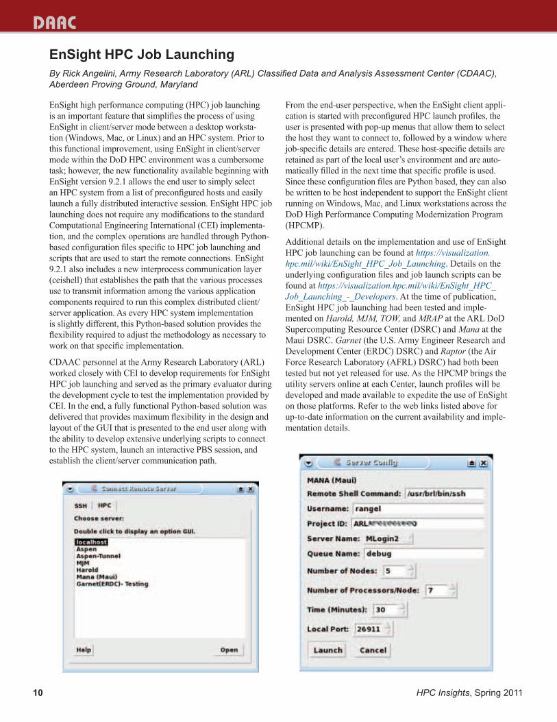
EnSight high performance computing (HPC) job launching is an important feature that simplifies the process of using EnSight in client/server mode between a desktop worksta-tion (Windows, Mac, or Linux) and an HPC system. Prior to this functional improvement, using EnSight in client/server mode within the DoD HPC environment was a cumbersome task; however, the new functionality available beginning with EnSight version 9.2.1 allows the end user to simply select an HPC system from a list of preconfigured hosts and easily launch a fully distributed interactive session. EnSight HPC job launching does not require any modifications to the standard Computational Engineering International (CEI) implementa-tion, and the complex operations are handled through Python-based configuration files specific to HPC job launching and scripts that are used to start the remote connections. EnSight 9.2.1 also includes a new interprocess communication layer (ceishell) that establishes the path that the various processes use to transmit information among the various application components required to run this complex distributed client/server application. As every HPC system implementation is slightly different, this Python-based solution provides the flexibility required to adjust the methodology as necessary to work on that specific implementation.
CDAAC personnel at the Army Research Laboratory (ARL) worked closely with CEI to develop requirements for EnSight HPC job launching and served as the primary evaluator during the development cycle to test the implementation provided by CEI. In the end, a fully functional Python-based solution was delivered that provides maximum flexibility in the design and layout of the GUI that is presented to the end user along with the ability to develop extensive underlying scripts to connect to the HPC system, launch an interactive PBS session, and establish the client/server communication path.
From the end-user perspective, when the EnSight client appli-cation is started with preconfigured HPC launch profiles, the user is presented with pop-up menus that allow them to select the host they want to connect to, followed by a window where job-specific details are entered. These host-specific details are retained as part of the local user’s environment and are auto-matically filled in the next time that specific profile is used. Since these configuration files are Python based, they can also be written to be host independent to support the EnSight client running on Windows, Mac, and Linux workstations across the DoD High Performance Computing Modernization Program (HPCMP).
Additional details on the implementation and use of EnSight HPC job launching can be found at https://visualization.hpc.mil/wiki/EnSight_HPC_Job_Launching. Details on the underlying configuration files and job launch scripts can be found at https://visualization.hpc.mil/wiki/EnSight_HPC_Job_Launching_-_Developers. At the time of publication, EnSight HPC job launching had been tested and imple-mented on Harold, MJM, TOW, and MRAP at the ARL DoD Supercomputing Resource Center (DSRC) and Mana at the Maui DSRC. Garnet (the U.S. Army Engineer Research and Development Center (ERDC) DSRC) and Raptor (the Air Force Research Laboratory (AFRL) DSRC) had both been tested but not yet released for use. As the HPCMP brings the utility servers online at each Center, launch profiles will be developed and made available to expedite the use of EnSight on those platforms. Refer to the web links listed above for up-to-date information on the current availability and imple-mentation details.
10 HPC Insights, Spring 2011

DAAC
Secure Remote Visualization ServicesBy Randall Hand, U.S. Army Engineer Research and Development Center, Data Analysis and Assessment Center (DAAC) Scientific Visualization Lead, Vicksburg, Mississippi
At the Data Analysis and Assessment Center, we’ve seen usage of remote visualization services like EnSight Server-of-Servers and ParaView Client-Server usage grow at exponential rates over the last few years. As the Program continues to deploy larger systems with larger disk arrays and more computational cycles at their disposal, users have begun running larger simulations and creating larger data-sets that exceed reasonable limits for FTP-ing down to local workstations. The ability to visualize data with it residing directly on the same system that generated it is attractive for not only the ability to access massive computational power, but for the rapid turnaround that’s possible when users don’t have to move the data long distances.
However, current client-server models have several prob-lems. Deployment is not consistent, typically requiring cus-tom configuration per application, per HPC, per user, and per operating system. Some sites make it virtually impossible to use remote client-server applications because of firewalls and security restrictions, while other sites make it trivial.
In an attempt to create a more consistent user experience, the DAAC has undertaken the creation of a new tool called “PKIVNC” that will be available on the utility server upon deployment. This new tool will provide a simple user inter-face to all HPCMP users, enabling them to get a full-blown Linux Desktop running directly on the utility server. Inside this desktop, they can run any application they desire, with full GPU acceleration if necessary, without having to worry about the intricacies of client-server deployment.
Initially, this will be useful for remote visualization ap-plications, providing a simple way of using EnSight and ParaView for visualizing data residing on the new Center-Wide File System (CWFS) immediately. Also, people with custom visualization applications or using older applications like TecPlot and FAST will be able to take advantage of these same features.
In addition, this will open a new generation of application debugging and code development tools for users, previ-ously unavailable to users because of bandwidth constraints. Interactive debugging tools like TotalView and DDT can be
run within this desktop environment, allowing users to monitor real-time execution of code. Code profilers, devel-opment environments, and much more will now be available for users to run on the utility server with full visuals.
The PKIVNC client-side applications will be available for download and for user access once the utility server enters production.
Figure 1. PKIVNC application
Figure 2. Connected to the Linux Desktop
HPC Insights, Spring 2011 11

12 HPC Insights, Spring 2011
IntroductionThere are numerous MATLAB users in the DoD. Its popular-ity arises from its simple, yet powerful, notation that allows scientists and engineers (S&Es) to quickly develop new codes or evaluate new numerical algorithms that in turn help build an effective fighting force. It has become an indispen-sible tool for many DoD S&Es. Many S&Es, however, have outgrown their one- or two-socket desktops and need more computational resources but have no place to turn.
High performance computing (HPC) also plays a key role in developing an effective fighting force, yet the number of S&Es, including MATLAB users, who take advantage of it, is far less than those who could benefit from it. For instance, there are approximately 25,000 S&Es in the Army Materiel Command alone, yet only about five percent of them use HPC. One reason is that traditional HPC requires a certain level of knowledge in parallel computing, Unix, job sched-uling, and scripting. Most S&Es prefer to focus on their specific application and do not have the time or organization mandate to become fluent in parallel computing.
MathWorks®, the maker of MATLAB, has developed prod-ucts called the Parallel Computing Toolbox™ (PCT) and the MATLAB Distributed Computing Server™ (MDCS). These products bring together MATLAB and HPC. The High Performance Computing Modernization Program (HPCMP) makes available significant HPC resources, but they are usually only accessible via the traditional HPC workflows: login, analyze, edit, and submit. So, for MATLAB, the pieces are there for increased computational power, but few S&Es take advantage of them because it is still not easy. Many would if these resources were tightly integrated and made widely available and easily accessible. The question is how to do this?
Microsoft has a suite of technologies that can be used to deliver Windows-based applications, including MATLAB, to DoD S&Es in a web portal. Their Remote Desktop technology has been used in business computing for many years and is an obvious choice for integrating remote scientific applications with the desktop. Microsoft also offers Windows HPC Server 2008 R2 that can provide computing power for computationally intensive, Windows-based applications. The MathWorks PCT/MDCS products are fully integrated with it. Because of this, the Army Research Laboratory (ARL) and the Maui High Performance Computing Center (MHPCC) are building a web portal based on these Microsoft technologies. Through the portal, DoD S&Es will have access to parallel computing from their familiar Windows desktop environment. They will be able
A User-Friendly HPC Web Portal for MATLAB® and Microsoft® Windows® ApplicationsPat Collins, Thomas Kendall, Jim Waterman, and Mike Knowles, Army Research Laboratory DoD Supercomputing Resource Center, Aberdeen Proving Ground, Maryland; Rob Fisher, High Performance Computing Modernization Program; and Andy Greenwell, John Dreatsoulas, and Tom Quinn, Microsoft
to accelerate their work by running many more simulations, more high-fidelity parallel simulations, or both.
This HPC web portal1 represents the start of the Defense Research and Engineering (DR&E) portal. ARL, the U.S. Army Engineer Research and Development Center (ERDC), MHPCC, and the HPCMP all recognize the need to make HPC more easily accessible and are cooperating to build the DR&E portal. The initial focus on MATLAB is because of its widespread use in the DoD. Other applica-tions will be added in time.
Portal ArchitectureThe portal is built on Microsoft Windows Server 2008 R2 platforms. The applications are published in a SharePoint website and delivered to the user via Microsoft’s RemoteApp technology. This technology is based on the Remote Desktop Protocol (RDP). It provides the mechanism for running an application on the portal and integrating its interface with the user’s desktop. Windows HPC Server 2008 R2 provides the computing resources.
The architecture is shown in Figure 1. All user access is through the CAC-authenticated https connections to the Forefront® Threat Management Gateway (TMG). The RemoteApp connections are bridged https connections to the Remote Desktop (RD) Gateway through which an RDP con-nection between the user and an application server is estab-lished. Before this connection is established, a connection is made to the broker who determines which application server has the fewest sessions running on it. The broker redirects the user to that server, and the selected application is started.
The Microsoft HPC server and the datacenter storage sys-tem are shown on the right in Figure 1. The head node is a single point of control for the HPC cluster. Cluster manage-ment is performed on the head node. It also runs the job scheduler and controls access to the HPC resources. The compute nodes provide the compute power to run parallel applications.
The architecture also includes an Active Directory with integrated Domain Name Service (DNS) that provides domain services (DS) and name-resolution services, and an RD License server that provides the necessary client access licenses.
1 The portal will be open to DoD scientists and engineers and their contractors. MATLAB will be restricted to portal users in the United States.

HPC Insights, Spring 2011 13
Using the Portal
To access the portal, a user points his browser to the website and authenticates using his CAC. The user then clicks the MATLAB icon on the web page (see Figure 2). This starts up MATLAB on an application server and displays the ap-plication GUI on the user’s desktop. Also published on the website is the Windows Explorer application. Clicking that icon brings up an Explorer window giving access to the user’s home directory on the portal. This is used to copy and paste files between the desktop and the portal. The user’s desktop file systems are available through the MATLAB graphical user interface (GUI) and can be used; however, these file systems are not available on the compute nodes of the HPC server. Portal home directories are accessible from all the compute nodes and application nodes.
At this point, the user has an instance of MATLAB available to him. To take advantage of HPC, he only needs familiar-ity with the MATLAB Parallel Computing Toolbox (PCT). Information on this can be found at MathWorks, Inc. 2011. The user’s profile includes a default HPC scheduler used by the PCT for accessing the HPC server. The user only has to worry about his code. When ready, the user submits his job using only the mechanisms provided by the PCT. Job sub-mission details are essentially hidden from the user. Because the MATLAB GUI is tightly integrated with the desktop, output data and graphics can be sent to the local printers or stored on the desktop.
Initial Operating CapabilityAt the initial operating capability (IOC), the portal will have 32 compute nodes and 8 application servers. Each compute node will have dual AMD, 8-core processors with 128 GB of memory. The system will have 36 TB of local storage. Tie-in to other file systems will not be available at IOC; however,
access to the Center-Wide File System is planned for the future. Supported clients will be Windows XP SP3, Vista, and Windows 7.
The system at IOC will support 16 concurrent MATLAB users and parallel jobs up to 512 MATLAB workers. All MATLAB toolboxes will be available for a limited period of time, enabling the portal team to gauge which toolboxes and what quantity should be provided on the portal.
SummaryMany DoD S&Es are familiar and comfortable with the Windows desktop. Many also run computationally intensive Windows applications on their desktop because they have no alternative platform. This Microsoft-based portal, while focused initially on MATLAB, will eventually provide
Figure 1. Portal architecture
Figure 2. MATLAB HPC portal website
14 HPC Insights, Spring 2011
computational resources to users of other Windows applica-tions that are currently confined to desktop and small server resources. These Windows applications could be highly parallel scientific application codes or just serial codes used in large parametric studies. It may also include Microsoft Excel running in parallel. In any case, a significant advan-tage would be realized.
MATLAB users will soon have a place to go for the compu-tational resources they need using their familiar Windows desktop environment without needing to become HPC ex-perts. Because the application does not need to be installed on the desktop, users will have much more flexibility. From home or while on travel, a user will be able to continue his work and not be tied to the desktop. The computational resources, the ease-of-use, and the flexibility will be a sig-nificant benefit to researchers engaged in developing new technologies that enable the U.S. warfighter to better per-form his mission.
The HPC Web Portal will be available in the fall of 2011. An announcement will be posted on the “News and Events” section of the MHPCC DSRC website, www.mhpcc.hpc.mil, when the system becomes available. More detailed informa-tion including how to apply for an account and run jobs will be posted at that time. Questions concerning this system can be sent to [email protected].
ReferencesMathWorks, Inc. (2011). Parallel Computing Toolbox. Retrieved from http://www.mathworks.com/products/parallel-computing/.
Special Considerations for Application Run SchedulingBy Christine Cuicchi, Computational Science and Applications Lead, Navy DoD Supercomputing Resource Center, Stennis Space Center, Mississippi
Exceptional requests, exciting science—while it is not often that users approach DSRCs with requirements of such size that involve staff intervention, the Navy DSRC is committed to assisting users in accomplishing greater achievements in computational science. One such user to avail himself of consideration for special scheduling accom-modations was Börje Andersson, who sought assistance with application scaling runs on DaVinci via the Consolidated Customer Assistance Center (CCAC). The requirements of Andersson’s scaling runs extended beyond the resource limits of the regular batch queues. The Navy DSRC staff reviewed these requirements and the expected scientific impact of the large runs, and coordinated with Andersson to stage these runs with minimal impact to batch users’ queue throughput.
The application used for these large-scale coordinated runs is the STRIPE code, a three-dimensional (3-D) hp-Finite Element Model (FEM) application developed at the Swedish Defense Research Agency (FOI). The STRIPE code was part of a Challenge project (Principal Investigator: Dr. Scott Fawaz, U.S. Air Force (USAF)) that supported the U.S. Air Force Aircraft Structural Integrity Program (ASIP), which addresses the structural integrity of the USAF C-130 aircraft—in particular, how those aircraft are affected by environmental degradation. The project focuses on the prediction of the remaining structural life of aging C-130s, which are likely to have numerous cracks in critical loca-tions in wings, fuselages, and other important structures
“NAVY/DAVINCI class hardware was required despite that our novel
mathematical analysis techniques yields savings on the order of 10^4
in computer time.”
because of battle damage and accumulated environmental degradation—most often corrosion—during the life of the aircraft. Examples of this type of damage to a C-130 center wing box can be seen in Figure 1.
“NAVY/DAVINCI class hardware was required despite that our novel mathematical analysis techniques yields savings on the order of 10^4 in computer time,” Andersson said. “The FEM-technology used is based on a unique multi-scale scheme, and the computational challenge is to get the methodology to scale 2-4 thousand processors when solv-ing structural analysis problems with billions of degrees of freedom, millions of times, i.e., for various fatigue scenario and aged conditions.” STRIPE uses MPI and OpenMP for several subtasks in the hp-version of FEM.
Scaling runs of up to 3072 cores were required to execute the STRIPE code on a small shell, 383 million degrees of freedom (DoF) dataset like the one pictured in Figure 2. Because the STRIPE code memory requirements prevent it
– Börje Andersson

HPC Insights, Spring 2011 15
from using the Simultaneous Multi-Threading (SMT) feature on DaVinci, the job runs were limited to using the 32 physi-cal cores per node as opposed to 64 virtual cores via SMT. This limitation further pushed the requirements of up to 96 nodes per run out of the bounds of regular batch queues. Arrangements were made with Andersson to prestage a 2048-core run to be executed immediately after a DaVinci preventative maintenance period, and several days later for a 3072-core run to be executed during normal production.
Prior to these scheduled runs, STRIPE had been shown to scale well up to 3072 cores during the 2008 Capability Application Projects (CAP) period on DaVinci. However, the STRIPE code had recently undergone revisions to “increase the I/O capacity by clustering data for read/write buffer size, resulting in fewer and larger datasets,” accord-ing to Andersson. Also according to Andersson, the impact of the larger runs scheduled by the Navy DSRC was quite measurable:
By using powerful systems like NAVY/DAVINCI and with support of CCAC [and the Navy DSRC] staff, it has for [the] first time been possible to analyze full aircraft fuselage parts with a resolution such that the crack growth scenario around each one of the tenths of thousands of rivets can be reliably predicted from initiation to final failure of the structural part, i.e., wing, etc. Data generated for structural parts can then be used for aircraft fleet management that is determin-ing inspection (of cracks) intervals, limiting loads on the aircraft (flight restrictions), and deciding when to repair and when to retire structural parts. True large-scale computations have been performed on DaVinci using several thousands of processors to obtain the objectives in a reasonable time. Computed data allow for so-called “virtual inspections,” that is, the inspector uses visualization to “fly throw the structure” while simultaneously inspecting critical areas (obtained from postprocessing of the computed data) and judging the possibility for human inspections on the real-life structure.
Environmentally Degraded StructureEnvironmentally Degraded, Repaired, and Degraded
Structure
Figure 1. C-130 center wing box with service-induced damage
Figure 2. Small global domain and typical local domain
Any users who wish to request special scheduling consider-ations at the Navy DSRC should contact CCAC for further information. While not all requests can be granted, staff will work with users individually to best meet their needs.
The author wishes to express great gratitude to Mr. Andersson for his valuable input into and assistance with this article.
DaVinci

16 HPC Insights, Spring 2011
HPCMP Enhanced User EnvironmentBy Michelle McDaniel, Air Force Research Laboratory (AFRL) DoD Supercomputing Resource Center, Wright-Patterson Air Force Base, Ohio; Paul Adams, U.S. Army Engineer Research and Development Center DoD Supercomputing Resource Center, Vicksburg, Mississippi; Chris Barnes, High Performance Computing Modernization Program; Reid Bingham, Army Research Laboratory DoD Supercomputing Resource Center, Aberdeen Proving Ground, Maryland; and John Gebhardt, AFRL
Whether you are a new or more seasoned user of the high performance computer (HPC) systems available through the High Performance Computing Modernization Program (HPCMP), the HPCMP Enhanced User Environment (HEUE) will bring significant changes to the way you utilize the HPC resources throughout the Program. These changes include everything from new user tools for data management to a small cluster designed for interactive processing.
This article is meant to identify things that you, as a user, need to be aware of and also provide an introduction to what you can expect while you’re using the new environment. These new resources are currently being integrated and tested in the DoD Supercomputing Resource Center (DSRC) environments with a pioneer user period scheduled to occur in April and a production transition across the Centers scheduled to occur this summer.
What Will Stay the Same?Although there will be changes, there will also be familiar aspects to the new environment. It’s important to recognize all facets to the new environment and not focus only on the differences. The following items will remain as they cur-rently are:
ª HPC login: you can still login directly to the HPCs. ª $HOME: you will still have a home directory on the HPCs. ª $WORKDIR: you can still continue to work in the scratch
directory. ª Job submittal: you can still submit jobs through qsub on
the HPCs. ª Data Scrubbing: you will still need to archive data you
want to keep or it will be scrubbed. ª Policies for HPC system jobs and the use of HPC system
login nodes.
In addition to the items that will remain the same, you will also receive new functionality through the Utility Server (US), the Center-Wide File System (CWFS), and the Storage Resource Broker (SRB ILM) Service.
What Will Be New?Utility Server (US)The Utility Servers are mixed node, small-scale HPCs de-signed and resourced for interactive processing, secure re-mote visualization services (SRVS), and much more. The US provides you a single location to complete all work if you so choose. The US is not intended for use as a small-scale HPC, though the hardware could be used that way.
Users will come in to login nodes and then use a resource manager (PBSpro) to request interactive sessions having one
or more “backend” nodes associated with that session. With the current resource manager technology, a request for inter-active session resources (qsub –I) will wait indefinitely at the command line until the resource request can be satisfied. Details of the resource groupings and operational policies are being finalized at the time of this article. Anticipated policies will include limits on node resources per user and time limits on sessions. Resource usage and request denials will be recorded for analysis to guide future policies. The current policy intent is to not charge allocations for interac-tive sessions. Batch jobs are discouraged, though not prohib-ited, and will be charged to allocations. Batch jobs will be subject to the node count and run time limits.
Jobs can be submitted and managed at a DSRC HPC through the Center-Wide Job Management (CWJM) system, using PBS’s qsub; pre- and postprocessing can be completed; large codes can be debugged more quickly; small, interac-tive jobs can run more effectively than through the HPC; and the US also provides a location for the Secure Remote Visualization Service.
Center-Wide Job Management (CWJM)The CWJM allows users to manage jobs on any unclassified HPC resource within a Center from a single login point, the US. From the US, users can submit, track, and delete jobs running on HPC resources within the Center, as well as jobs running on the US. A job submitted to an HPC resource through the US can be tracked and deleted either through the US or by logging into the HPC resource.
Secure Remote Visualization Services (SRVS) The SRVS is a client-server model integrated with the HPCMP security stack to deliver pixels from a virtual US-node desktop to the user’s desktop over a wide-area network. One application currently ready for production is the Public Key Infrastructure (PKI) Virtual Network Computing (VNC) or PKIVNC. This application allows a remote user to se-curely access a Linux desktop on the US. This allows a user to run ParaView, EnSight, Matlab, or any other software program that can run on Linux. Additional applications will also be available.
Center-Wide File System (CWFS)The CWFS provides an unprecedented 1PB of disk storage at each Center. This will provide up to 30 days of near HPC storage without having to use the tape archive. This gives you a longer time to verify, analyze, and archive job results than currently offered at the Centers (10 days best effort). The CWFS will provide 30 days of temporary storage. Users must archive their data (it is not an automatic process as it

HPC Insights, Spring 2011 17
currently is) during this time. These 30 days should be uti-lized to complete any postprocessing or visualization on the US. After 30 days, the data will be scrubbed and cannot be recovered.
Storage Resource Broker (SRB)The SRB is a secure application that is a part of the login and batch environment of each system. The SRB client will be an additional tool to copy data among the various data stores in a DSRC environment and will be the only way to interact with the ILM archive service. It can be used through either command line or a graphical user interface (GUI) (if permitted by the Center).
The SRB will use metadata provided by you, the user, to help you maintain and track your archived data. You must provide a project identifier and a retention date that tells the system when these data can be deleted from the ILM ar-chive. Regardless of how long a retention time you specify, you will be requested to review and affirm that retention time decision at least every 3 years. You will receive mul-tiple review notifications as a reminder to check your data as they get closer to the end of the retention time.
How Will the New Resource Manager Options Be Used on the Utility Server?Running a jobYou would like to run a job that will include pre- and postprocessing data. First, all input data must be placed in a single location by logging into the US and running stan-dard tools and the SRB Client on the US login node. At the HEUE introduction, copying data around the DSRC environ-ment has the added complexity in understanding when using the SRB Client is optional versus the only option. As the HEUE matures and additional technologies can be inserted, we hope to simplify that situation.
After the data have been moved, you will log into your local US to preprocess some data. You might look to see who is running on the system to see if there are enough nodes avail-able. Seeing that there are nodes available, you will ask for resources to have enough memory to generate a large grid for processing on another HPC resource.
$ qsub –l select=1:ncpus =32 mem=256gb –A project_name –I
This will get you one large-shared memory node on the US with up to 32 CPUs and 256 GB of memory. You can then generate a grid.
After the grid is generated, you will use the CWJM to sub-mit a job to the transfer queue on the US to prepare data for the job that will run on the HPC via batch; the output files will be located on the HPC scratch filesystem and should be transferred back to the CWFS using the SRB or standard copy tools, preferably in a transfer queue job. This can all be included in your submission script. The script should also include the SRB file registration information (your metadata tags or any keywords that may be needed).
Archiving dataAfter a job has completed, and postprocessing is not re-quired, data can be archived. Data will automatically be placed on the CWFS with a 30-day retention time. You will be notified of upcoming deletion as it gets closer. You must archive your data using the SRB command Sput or risk data loss. The SRB command Sretain or the java client must be used to set a new retention time after the default review time has expired (30 days).
More training on the SRB will be provided via the HPCMP “What’s New” newsletter, the web, and the Consolidated Customer Assistance Center (CCAC) User Portal.
Debug large codeYou may want to debug a large code that is particularly troublesome. You will login to the US and see who is run-ning on the system. Seeing that there are nodes available, you will ask for resources that allow you to have enough cores to test your code:
$ qsub –l select=16:ncpus =16 –A project_name –I
This will get 16 compute nodes on the US with up to 16 CPUs for 256 cores in total. An alternate way to ask for this amount of CPUs would be to use the following command line:
$ qsub –l select=8:ncpus =32 –A project_name –I
This will get 8 large shared-memory nodes on the US with up to 32 CPUs for 256 cores in total. There is no real advan-tage to either method for getting the cores. In either case, you will have 256 cores with 8 GB of memory per core.
General Purpose Computation on Graphical Processing Units (GPGPU)You may want to use the US to complete GPGPU develop-ment or analysis. After your login to the US, you look to see who is running on the system. Seeing that there are graphics nodes available, you will ask for resources that allow you to have the cores to test out your code.
$ qsub –l select=16:ngpus =16 –A project_name –I
This will get you 16 graphics nodes on the US with up to 16 CPUs for 256 cores in total. In addition, you will have ac-cess to 16 NVIDIA Tesla M2050 graphics cards to perform CUDA environment computation.
The HEUE will bring new, exciting resources and function-ality to HPCMP users. All of the announced information is available at https://help.ccac.hpc.mil/docs/index.html. Additional training will be available online and at the Users Group Conference. If you have any questions regarding the HEUE, you can contact CCAC at 1-866-222-2039.

18 HPC Insights, Spring 2011
IntroductionKestrel is a high-fidelity, full-vehicle, multiphysics analysis tool for fixed-wing aircraft. It is a new, integrated product that allows crossover between simulation of aerodynamics, dynamic stability and control, structures, propulsion, and stores separation. The Kestrel software product is written in modular form with a Python infrastructure to allow growth for additional capabilities, as needed. Computational effi-ciency will also be improved by targeting the next-generation petaflop architectures envisioned for the 2011 time frame. Kestrel is also targeted toward simulating multidisciplinary physics such as fluid-structure interactions, inclusion of propulsion effects, moving control surfaces, and coupled flight control systems. The Kestrel software product addresses these needs for fixed-wing aircraft in flight regimes ranging from subsonic through supersonic flight, including maneuvers, multiaircraft configurations, and operational conditions.
Kestrel utilization of the Air Force Research Laboratory (AFRL) resources at MHPCC, 16 July 2010 – 30 September 2010, resulted in nearly 2.8 million CPU-hours of compute time used.
TestingKestrel v2.0 Quality Assurance Tests (QAT) were conducted in September 2010, after the Alpha tests had been completed. QAT greatly benefited from the dedicated high performance computing (HPC) computer time provided at MHPCC (2000 compute cores). The cases evaluated, ranging from grid sizes of 3 million to 80 million grid points, are briefly summarized in the table below.
Kestrel: A High-Fidelity, Full-Vehicle, Multiphysics Analysis Tool for Fixed-Wing AircraftBy Marie Greene, Deputy Director, Maui High Performance Computing Center DoD Supercomputing Resource Center, Maui, Hawaii
Testing Statistics:
ª Total Jobs Submitted to the Queue – 1377 ª Total Jobs Completed – 682 ª Total CRs Filed/Fixed – 104/99 ª Approximate Utilization – 80 percent (excludes
maintenance/downtime)
DoD ImpactSimulations are being computed for the F-15E, F-16C, F-18C, C-17, and C-130 by the Kestrel team, and Kestrel users are computing solutions for the F-22, F-35, and E2D, as well as various UAVs.
The availability of the dedicated Mana system at MHPCC significantly impacted the QAT execution:
1. QAT was a dynamic and interrogative Grid Refinement of NACA0015.
2. CREATE-AV codes—Kestrel in this instance—are targeting real-world geometries and difficult physics. The predicted solutions are determined by the triad of physics, numerics, and grid quality. Solution sensitiv-ity to model parameters for full-scale simulations has to be well understood prior to providing advisories for the engineering user. The availability of the dedicated cores enabled such studies.
3. Grid refinement and its consequences to real-world models were vetted out to a limited extent in QAT.
Grid refinement of NACA0015
“I cannot overemphasize how important it was to have the (MHPCC) resource. This amount
of progress was not possible without Mana (MHPCC’s system). Finding and correcting
over 100 deficiencies was huge!” – Dr. Scott Morton
Value AddedAs a result of the resources provided by MHPCC and the pro-fessional services provided by the MHPCC staff, the Kestrel development team and the CREATE-AV Quality Assurance group accomplished in 10 weeks what took more than 5 months in FY2009. In addition to the significant reduction in the development cycle time, Kestrel was able to conduct a significantly more extensive and thorough testing program.
Between the Alpha testing and the Product Acceptance testing, nearly 1500 jobs were processed, resulting in 104 issues identified. Dr. Scott Morton, Kestrel Principal Developer, praised the MHPCC team and commented, “I cannot over-emphasize how important it was to have the (MHPCC) resource. This amount of progress was not possible without Mana (MHPCC’s system). Finding and correcting over 100 deficiencies was huge!”
AcknowledgmentsSome of the material presented in this article is a product of the Kestrel testing summaries provided by the CREATE Program Manager, Dr. Douglass Post; the Kestrel Principal Developer, Dr. Scott Morton; and the CREATE-AV (Air Vehicles) element of the CREATE Program.

HPC Insights, Spring 2011 19
Improve Job Throughput in One Easy StepBy Bryan Comstock, Systems Analyst, Navy DoD Supercomputing Resource Center, Stennis Space Center, Mississippi
Ever feel like your job is just waiting in bumper-to-bumper traffic? We’ve all been there before. Take a job number, wait your turn—repeat this sequence over and over. That doesn’t have to be the case, though. There are several mechanisms—some manual, some automatic—in place that allow jobs to essentially move to the front of the line.
The Navy DSRC constantly monitors the batch workloads on our two HPC systems, Einstein and DaVinci. This is done to ensure the batch scheduler, PBSPro, is functioning properly. The systems tend to stay active and have had good utilization numbers during their time at the Centers. During the first quarter of FY11, both DaVinci and Einstein have averaged around 80 percent utilization.
Opportunities exist for users to improve their throughput in the queues by tuning batch script walltime requests. It’s understood that a user may decide to implement a walltime buffer, a padding of additional requested walltime, in case the code needs to run longer than normal. It has been ob-served, however, that some of these “buffers” can be exceed-ingly large, which leads to scheduler inefficiency. These oversized buffers could also be caused by a simple mistake such as copying an old script and not tailoring it to the cur-rent job run.
The most important mechanism to enhance your job throughput is called backfill. Backfill automatically occurs when the scheduler is trying to make resources (nodes and time) available for a “top” job, i.e., the job at the front of the priority-based line. The scheduler will look at the resource requests of eligible jobs behind the top job in the queues and determine whether it has a large enough window with enough nodes available to run the lower priority jobs. The scheduler is blind to how long a job will actually run and can only base its job start time estimates on what is asked of it in terms of wallclock time, as well as node resources, required. Clearly then, if you are able to tune a batch script’s resource requests to better fit the job, it can improve job turnaround, thus potentially decreasing your overall time-to-solution.
It’s also important to note that the Advance Reservation System (ARS) implementation on both systems allows for backfill onto idle ARS nodes. Jobs that request 24 hours or less of walltime and that can fit within the ARS por-tion of the system are allowed to backfill into ARS nodes. On DaVinci, this is an automatic process. On Einstein, the implementation of ARS is different because of the overall ar-chitecture of the system, and the backfill method is scripted but efficient. With each system’s ARS core count equaling 25 percent of the total system core count, a large number of nodes are available for quicker turnaround given the proper job profile.
PBS job record data were gathered on those jobs that are ineligible for ARS backfill, and that may be more difficult to backfill via PBSPro’s traditional backfill mechanism. The data collected only relates to jobs that ran longer than 24 hours in the first quarter of FY11. By examining the data and the patterns that exist in it, one can conclude that users are impacting the efficiency of the PBSPro scheduler be-cause of oversized walltime requests.
A simple example follows: User A submits a single 168-hour wallclock job. The user may or may not know whether the job truly needs the full wallclock time; but by asking for the maximum amount of walltime allowed on that queue, the user is essentially telling the scheduler that this job can’t be backfilled. The job will not fit within the ARS guidelines for backfill (wallclock <= 24 hours), and the scheduler will not be able to fit User A’s job in front of another job because of its request for maximum walltime allowable. Now User A’s job must truly wait its turn in line, thus pushing out the time-to-solution.
Tables A and B present job data gathered for Einstein and DaVinci, respectively. These data include varying job sizes, walltimes requested, the delta between requested and actual walltime, and the percentage of walltime overages.
Of note in Table A is that nearly every class of work re-quested a 25 percent wallclock buffer. The only data for the 257+ node count group comes from a single project that has encountered system issues causing some jobs to die prema-turely, so those data points are not useful for the purpose of this analysis. This same project was also impacted by a PBSPro bug that prevented these large, long-running jobs from being scheduled to run within an acceptable amount of queue wait time. The system issue that caused the small number of jobs to die prematurely is expected to be resolved

20 HPC Insights, Spring 2011
as of press time, and the PBSPro bug has been fixed with a software patch.
On DaVinci, the wallclock buffer requested by users tends to be smaller, and the job size range was much more compact. It is unclear whether users of DaVinci are better at estimating job length requirements.
It should be noted that there were half as many jobs found on DaVinci that fit this study’s criteria compared with Einstein. Job exit codes, which signify the state of the job when it stopped running, were not examined in this study. It is likely that some of the data collected included jobs that terminated earlier than the requested wallclock time for various reasons.
In any case, a more correct estimation of wallclock require-ments will help the user achieve better job turnaround. This in turn will contribute to better job turnaround times for other users.
There exist clear trends in the data that some users are simply overestimating what the job actually requires, and in the end, hurting overall turnaround and time-to-solution, not just for them but also potentially for others. Taking care to properly estimate near actual required wallclock times, perhaps using walltime data obtained via smaller scale jobs, will allow the scheduler to more efficiently do its job while also providing the user with better overall turnaround and time-to-solution.
After my long history of service in the ERDC DoD Super-computing Resource Center (DSRC), beginning as a part of the source selection evaluation team for the original DSRC procurements and ending after several years as the DSRC Director, I continue to serve in a related field. In my present capacity as a special assistant to Dr. Reed Mosher, ERDC Information Technology Laboratory (ITL) Director, I initiated a lecture series on large-scale computing on behalf of ITL.
A revolutionary strategy for high performance computing (HPC) is required to exploit new device technologies in order to achieve exaFLOPS performance (1,000,000,000,000,000,000 floating operations per second) by 2020 or earlier. This lecture series provides insight to HPC users on the issues, challenges, and opportunities presented by the next one thousandfold increase in supercomputing capability. Dr. Thomas Sterling, one of the central figures shaping the future of supercom-puting today, began the lecture series last fall with his talk on “Revolution as a Catalyst for the Exascale Computing Phase Change.” Dr. Sterling is a professor of computer sci-ence at Louisiana State University, a faculty associate at the California Institute of Technology, a CSRI Fellow for Sandia National Laboratories, and a Distinguished Visiting Scientist at Oak Ridge National Laboratory. He outlined potential ele-ments of a new strategy for large-scale computing and their value to meeting the challenges we will face in reaching systems capable of a quintillion floating point operations per second in less than 10 years. Included were key ideas that will separate future HPC systems from those of the current generation—information you’ll need to build applications that can take advantage of tomorrow’s supercomputers.
In the second lecture of the series, Dr. Kelly Gaither, Texas Advanced Computing Center, presented “From Information to Insight: The Challenges of Data Analysis at Extreme Scale” in which she said that as computational resources, sensor networks, and other large-scale instruments and
Lecture Series on Large-Scale ComputingBy John E. West, Special Assistant to Director, Information Technology Laboratory, U.S. Army Engineer Research and Development Center, Vicksburg, Mississippi
experiments grow, the quantity of data generated from these sources is also growing. She added that in order for data to have meaning, it must be processed, analyzed, and trans-formed to yield information of value. Many of the standard approaches in scientific visualization break down at the petabyte scales of many of the datasets of interest to the scientific communities. Even when they don’t explicitly fail, classical ways of processing data may simply present too much information to the analyst and undermine the ability to see what’s relevant. Dr. Gaither explored these issues and addressed the evolving state of the practice in managing and understanding the large-scale datasets of interest to the com-putational science community.
Dr. Dan Reed, Microsoft Research, presented his views on the future of large-scale computing across the entire spec-trum of human activity, from the “silent” cycles consumed on our behalf in the cloud infrastructure to the specialized, high performance scientific computing that is a key enabler in the kinds of work ERDC does for its customers today. His March 2011 lecture titled “Insights for the Future of Computing” included key ideas about the technologies that are likely to be a part of future hardware and software and their organization into computing systems that will help with plans to build applications that can take advantage of tomor-row’s computing capabilities. As Corporate Vice President of Technology Policy and Strategy and leader of the eXtreme Computing Group (XCG), Dr. Reed helps shape Microsoft’s long-term vision and strategy for technology innovations and the company’s associated policy engagement with governments and institutions around the world. Given the centrality of information technology to communication and social interaction, research and development, education and learning, health and safety, the environment and economic development, such strategic technology identification and policy coordination are critical to our future. In this capacity, Dr. Reed reports to and works closely with Craig Mundie,

HPC Insights, Spring 2011 21
Microsoft’s Chief Research and Strategy Officer. As leader of XCG within Microsoft Research (MSR), he is responsible for R&D on the leading edge of parallel and ultrafast com-puting, as well as Microsoft’s cloud computing research. In addition to directing Microsoft’s research in these areas, he spearheads collaborations with university and government researchers working in the field.
Dr. Rick Stevens, Argonne National Laboratory and the University of Chicago, will present the fourth lecture in this series in May 2011, at which time this publication will be at press. In his talk titled “The Future of Computing: 10 Years to Exascale,” Dr. Stevens will discuss his views on the fu-ture of large-scale scientific computing and what steps the Department of Energy is taking to make exascale computing not only possible but applicable to problems of national significance during this decade. The transition to supercom-puters capable of 10^18 floating point operations per second (FLOPS) is especially challenging, presenting difficulties
in power, operating systems, and algorithms that have some in the high-end community calling for a fundamentally new model of computing. This unique talk will give attendees a chance to hear from one of the central figures actually likely to build an exascale computer in the next decade. The talk will include key ideas about the technologies that are likely to be a part of future hardware and software, and their organization into computing systems that will help you plan to build applications that can take advantage of tomorrow’s supercomputers.
The sessions of the lecture series have been well attended by scientists and engineers from all four ERDC laboratories located on the ERDC Headquarters campus who presently use (or plan to do so) resources provided by the DoD High Performance Computing Modernization Program. Many of our HPC users would it find it beneficial and interesting to attend presentations by these outstanding leaders in the field of large-scale computing. Videos of each lecture session are available online at http://itl.erdc.usace.army.mil/videos_lsels.
IntroductionCross-platform software development in a heterogeneous computing environment can be an arduous undertaking. Dealing with machine-specific compilers, message pass-ing toolkits, and varying system libraries can make the process frustrating if not nearly impossible. Over the past several years the Classifed Data Analysis and Assessment Center (CDAAC) together with the Computational Sciences and Engineering Branch (CSEB) of the Army Research Laboratory endeavored to simplify and streamline this pro-cess by creating the Computational Science Environment (CSE). By integrating a relatively large collection of open-source and custom-developed software tools into a common cross-platform environment, CSE can reduce the effort needed to develop new software that is able to take advan-tage of the variety of computational systems available across the High Performance Computing Modernization Program (HPCMP).
Over the last decade the CDAAC and the CSEB have been heavily involved in tool development, code coupling, and data conversion both for general data analysis and visualization. The packages integrated into CSE have largely been a result of what has proven useful to support these projects in a cross-platform environment. From the early adoption of Tcl/Tk, Python, and VTK to more recent additions like scipy, octave, matplotlib, as well as the addition of GIT as the software repository and CMake as the overarching build system, CSE has evolved into a relatively comprehensive cross-platform development environment. In late 2010, the HPCMP Baseline Configuration Team selected CSE to be deployed at all sites available to DoD users through the HPCMP.
Using CSE for Software DevelopmentBy Carrie Spear, Joel Martin, John Vines, and Eric Mark, Army Research Laboratory, Aberdeen Proving Ground, Maryland
The following descriptions and examples are presented to give a prospective user an idea of how the CSE can be used to support software development.
Compiling CSECSE is available at all of the DoD Supercomputing Resource Centers (DSRCs). It is also available to download and build on your local system. Instructions for downloading, building, and installing can be found at
http://www.arl.hpc.mil/SciVis/cse.html
CSE for DevelopmentCSE incorporates many industry standard-software- development application programming interfaces (APIs), scripting languages, and other software utilities to assist developers with software development projects.
To take advantage of these prebuilt software packages in the CSE, a developer needs to
1. Load the CSE environment � module load cseinit
The CSE loads a default compiler and message passing interface (MPI).
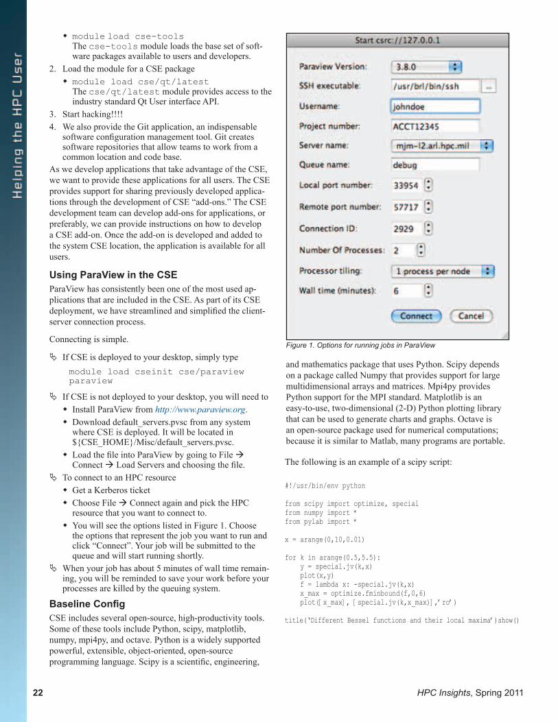
22 HPC Insights, Spring 2011
� module load cse-tools The cse-tools module loads the base set of soft-ware packages available to users and developers.
2. Load the module for a CSE package � module load cse/qt/latest
The cse/qt/latest module provides access to the industry standard Qt User interface API.
3. Start hacking!!!!4. We also provide the Git application, an indispensable
software configuration management tool. Git creates software repositories that allow teams to work from a common location and code base.
As we develop applications that take advantage of the CSE, we want to provide these applications for all users. The CSE provides support for sharing previously developed applica-tions through the development of CSE “add-ons.” The CSE development team can develop add-ons for applications, or preferably, we can provide instructions on how to develop a CSE add-on. Once the add-on is developed and added to the system CSE location, the application is available for all users.
Using ParaView in the CSEParaView has consistently been one of the most used ap-plications that are included in the CSE. As part of its CSE deployment, we have streamlined and simplified the client-server connection process.
Connecting is simple.
ª If CSE is deployed to your desktop, simply typemodule load cseinit cse/paraview paraview
ª If CSE is not deployed to your desktop, you will need to � Install ParaView from http://www.paraview.org. � Download default_servers.pvsc from any system
where CSE is deployed. It will be located in ${CSE_HOME}/Misc/default_servers.pvsc.
� Load the file into ParaView by going to File àConnect à Load Servers and choosing the file.
ª To connect to an HPC resource � Get a Kerberos ticket � Choose File à Connect again and pick the HPC
resource that you want to connect to. � You will see the options listed in Figure 1. Choose
the options that represent the job you want to run and click “Connect”. Your job will be submitted to the queue and will start running shortly.
ª When your job has about 5 minutes of wall time remain-ing, you will be reminded to save your work before your processes are killed by the queuing system.
Baseline ConfigCSE includes several open-source, high-productivity tools. Some of these tools include Python, scipy, matplotlib, numpy, mpi4py, and octave. Python is a widely supported powerful, extensible, object-oriented, open-source programming language. Scipy is a scientific, engineering,
Figure 1. Options for running jobs in ParaView
and mathematics package that uses Python. Scipy depends on a package called Numpy that provides support for large multidimensional arrays and matrices. Mpi4py provides Python support for the MPI standard. Matplotlib is an easy-to-use, two-dimensional (2-D) Python plotting library that can be used to generate charts and graphs. Octave is an open-source package used for numerical computations; because it is similar to Matlab, many programs are portable.
The following is an example of a scipy script:
#!/usr/bin/env python
from scipy import optimize, specialfrom numpy import *from pylab import *
x = arange(0,10,0.01)
for k in arange(0.5,5.5): y = special.jv(k,x) plot(x,y) f = lambda x: -special.jv(k,x) x_max = optimize.fminbound(f,0,6) plot([x_max], [special.jv(k,x_max)],’ro’)
title(‘Different Bessel functions and their local maxima’)show()
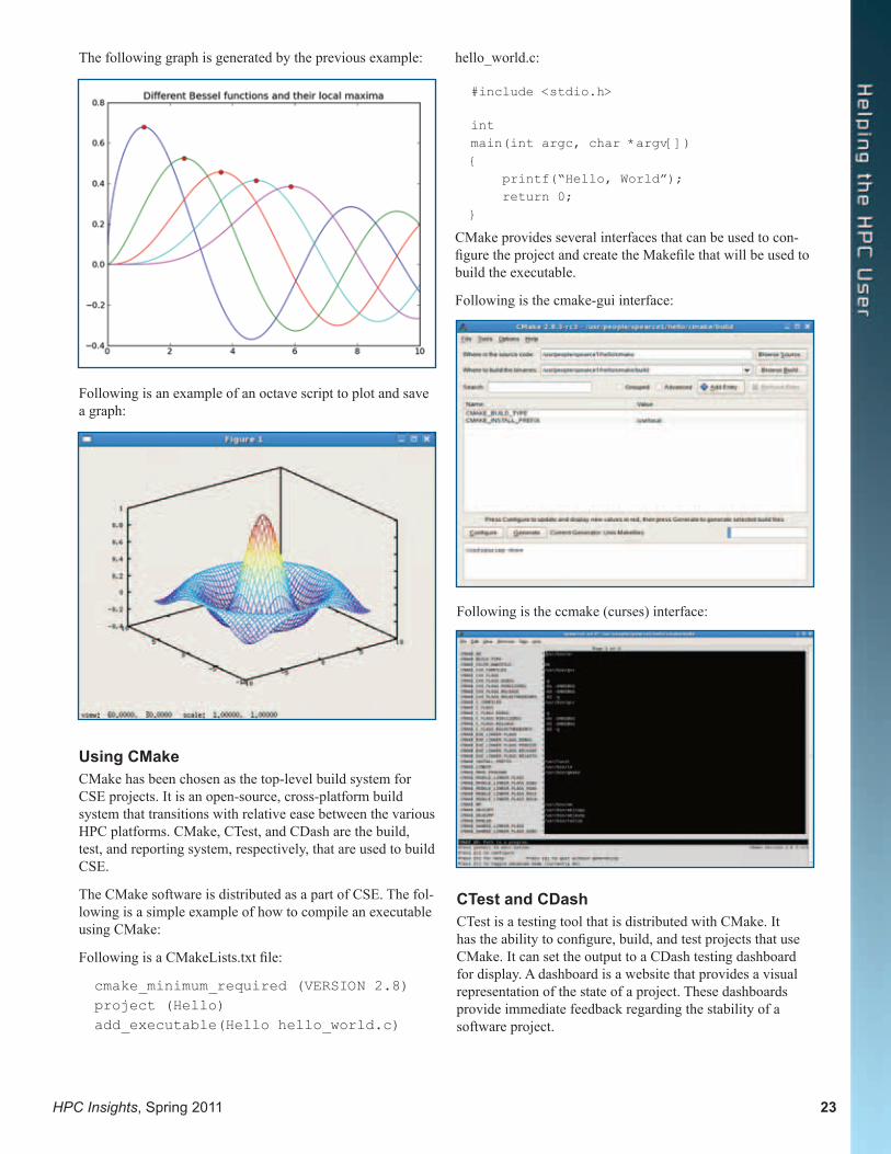
HPC Insights, Spring 2011 23
Using CMakeCMake has been chosen as the top-level build system for CSE projects. It is an open-source, cross-platform build system that transitions with relative ease between the various HPC platforms. CMake, CTest, and CDash are the build, test, and reporting system, respectively, that are used to build CSE.
The CMake software is distributed as a part of CSE. The fol-lowing is a simple example of how to compile an executable using CMake:
Following is a CMakeLists.txt file:
cmake_minimum_required (VERSION 2.8)project (Hello)add_executable(Hello hello_world.c)
Following is the ccmake (curses) interface:
CTest and CDashCTest is a testing tool that is distributed with CMake. It has the ability to configure, build, and test projects that use CMake. It can set the output to a CDash testing dashboard for display. A dashboard is a website that provides a visual representation of the state of a project. These dashboards provide immediate feedback regarding the stability of a software project.
The following graph is generated by the previous example:
Following is an example of an octave script to plot and save a graph:
hello_world.c:
#include <stdio.h>
intmain(int argc, char *argv[]){ printf(“Hello, World”); return 0;}
CMake provides several interfaces that can be used to con-figure the project and create the Makefile that will be used to build the executable.
Following is the cmake-gui interface:
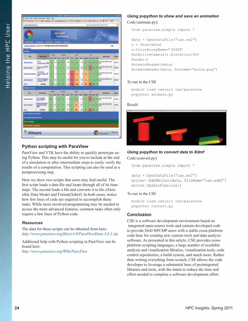
24 HPC Insights, Spring 2011
Python scripting with ParaViewParaView and VTK have the ability to quickly prototype us-ing Python. This may be useful for you to include at the end of a simulation or after intermediate steps to easily verify the results of a computation. This scripting can also be used as a postprocessing step.
Here we show two scripts that users may find useful. The first script loads a data file and loops through all of its time-steps. The second loads a file and converts it to the eXten-sible Data Model and Format(Xdmf). In both cases, notice how few lines of code are required to accomplish these tasks. While more involved programming may be needed to access the more advanced features, common tasks often only require a few lines of Python code.
ResourcesThe data for these scripts can be obtained from here: http://www.paraview.org/files/v3.8/ParaViewData-3.8.1.zip
Additional help with Python scripting in ParaView can be found here: http://www.paraview.org/Wiki/ParaView
Using pvpython to show and save an animationCode (animate.py):
from paraview.simple import *
data = OpenDataFile(“can.ex2”)s = Show(data)s.ColorArrayName=’DISPL’GetActiveCamera().Elevation(90)Render()AnimateReader(data)AnimateReader(data, filename=”movie.png”)
To run in the CSE
module load cseinit cse/paraviewpvpython animate.py
Result:
Using pvpython to convert data to XdmfCode (convert.py):
from paraview.simple import *
data = OpenDataFile(“can.ex2”)writer= XdmfWriter(data, FileName=”can.xdmf”)writer.UpdatePipeline()
To run in the CSE
module load cseinit cse/paraviewpvpython convert.py
ConclusionCSE is a software development environment based on integrated open-source tools and custom-developed code to provide DoD HPCMP users with a stable cross-platform code base for creating new custom tools and data analysis software. As presented in this article, CSE provides cross- platform scripting languages, a large number of available analysis and visualization libraries, visualization tools, code control repositories, a build system, and much more. Rather than writing everything from scratch, CSE allows the code developer to leverage a substantial base of preintegrated libraries and tools, with the intent to reduce the time and effort needed to complete a software development effort.
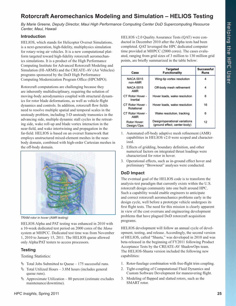
HPC Insights, Spring 2011 25
IntroductionHELIOS, which stands for Helicopter Overset Simulations, is a next-generation, high-fidelity, multiphysics simulation for rotary-wing air vehicles. It is a new computational plat-form targeted toward high-fidelity rotorcraft aeromechan-ics simulations. It is a product of the High Performance Computing Institute for Advanced Rotorcraft Modeling and Simulation (HI-ARMS) and the CREATE-AV (Air Vehicles) programs sponsored by the DoD High Performance Computing Modernization Program Office (HPCMPO).
Rotorcraft computations are challenging because they are inherently multidisciplinary, requiring the solution of moving-body aerodynamics coupled with structural dynam-ics for rotor blade deformations, as well as vehicle flight dynamics and controls. In addition, rotorcraft flow fields need to resolve multiple spatial and temporal scales in the unsteady problem, including 3-D unsteady transonics in the advancing side, multiple dynamic stall cycles in the retreat-ing side, wake roll-up and blade vortex interaction in the near-field, and wake intertwining and propagation in the far-field. HELIOS is based on an overset framework that employs unstructured mixed-element meshes in the near-body domain, combined with high-order Cartesian meshes in the off-body domain.
Rotorcraft Aeromechanics Modeling and Simulation – HELIOS TestingBy Marie Greene, Deputy Director, Maui High Performance Computing Center DoD Supercomputing Resource Center, Maui, Hawaii
TRAM rotor in hover (AMR testing)
HELIOS Alpha and PAT testing was enhanced in 2010 with a 10-week dedicated test period on 2000 cores of the Mana system at MHPCC. Dedicated test time was from November 1, 2010 to January 15, 2011. The HELIOS queue allowed only Alpha/PAT testers to access processors.
TestingTesting Statistics:
ª Total Jobs Submitted to Queue – 175 successful runs. ª Total Utilized Hours – 3.8M hours (includes general
queue runs). ª Approximate Utilization – 80 percent (estimate excludes
maintenance/downtime).
HELIOS v2.0 Quality Assurance Tests (QAT) were con-ducted in December 2010 after the Alpha tests had been completed. QAT leveraged the HPC dedicated computer time provided at MHPCC (2000 cores). The cases evalu-ated, ranging from grid sizes of 3 million to 130 million grid points, are briefly summarized in the table below:
1. Automated off-body adaptive mesh refinement (AMR) capabilities in HELIOS v2.0 were scoped and character-ized.
2. Effects of gridding, boundary definition, and other numerical factors on integrated thrust loadings were characterized for rotor in hover.
3. Operational effects, such as in-ground effect hover and preliminary “Brownout” analyses were conducted.
DoD ImpactThe eventual goal of the HELIOS code is to transform the analysis-test paradigm that currently exists within the U.S. rotorcraft design community into one built around HPC. Such a capability would enable engineers to anticipate and correct rotorcraft aeromechanics problems early in the design cycle, well before a prototype vehicle undergoes its first flight tests. The need for this mission is clearly apparent in view of the cost overruns and engineering development problems that have plagued DoD rotorcraft acquisition programs.
HELIOS development will follow an annual cycle of devel-opment, testing, and release. Accordingly, the second version of HELIOS, called “Shasta,” was developed in 2010 and was beta-released in the beginning of FY2011 following Product Acceptance Tests by the CREATE-AV ShadowOps team. The HELIOS-Shasta version included the following new capabilities:
1. Rotor-fuselage combination with free-flight trim coupling. 2. Tight-coupling of Computational Fluid Dynamics and
Custom Software Development for maneuvering flight.3. Modeling of flapped and slatted rotors, such as the
SMART rotor.
26 HPC Insights, Spring 2011
4. Helicopter modeling with stores separation with pre-scribed motion of the stores.
In addition to these basic capability enhancements, a number of functional enhancements are envisioned that include the following:
1. Automated off-body AMR using feature-detection meth-odology.
2. Development of a load-balancing module to facilitate dynamic repartitioning of the near-body and off-body problems to allow for the growth in off-body mesh points because of the AMR process.
3. Enhanced interface specification strategy for all compo-nents to facilitate interoperability of components among different CREATE-AV products.
4. Generalized interfaces for structural dynamics and trim to allow plugging in of appropriate comprehensive analy-sis packages. It is anticipated that these enhancements would lead to improved performance predictions, better resolution of the tip vortices in the far-wake, as well as enhanced scalability. Moreover, the generalized inter-faces would enable component inter-operability among CREATE-AV products, as well as facilitate collaboration with the broader research community.
Value AddedHELIOS testing at MHPCC was extremely beneficial for the following:
1. Debugging: dozens of bugs and issues filed and fixed as a result of dedicated testing.
2. Optimization of solver parameters: Courant–Friedrichs–Lewy number, time-stepping options, multigrid.
3. Assessment of AMR.4. Validation of key capabilities for hover and forward
flight.
AcknowledgmentsMaterial presented in this article is a product of the testing summaries provided by the CREATE Program Manager, Dr. Douglass Post, and the CREATE-AV (Air Vehicles) element of the CREATE Program sponsored by the U.S. DoD HPCMPO. Development of HELIOS was performed at the HPC Institute for Advanced Rotorcraft Modeling and Simulation (HI-ARMS) located at the U.S. Army Aeroflightdynamics Directorate at Moffett Field, California.
Expanding on a request received from a user, the Baseline Configuration (BC) team has developed a common command for checking the status of 12 DoD High Performance Computing Modernization Program (HPCMP) shared applications. To check the status of any of these applications, the command check_license is given followed by the application name.
In March 2010, a DoD HPCMP user communicated with the BC team expressing interest in a common command to check the status of “Abaqus” licenses across all of the DoD Supercomputing Resource Centers (DSRCs).
The BC team discussed the user’s request at one of its weekly teleconferences on April 20 and decided to broaden the user’s request by developing a common command for checking the status of not only Abaqus licenses but also all core-based applications installed at the DSRCs.
As in most cases, the BC team collaborates with available expertise within the HPCMP in order to accomplish a specific task. For this specific task, Jonathan O’Reilly, formerly an ARL substitute on the BC team, volunteered to develop the capability.
The common command for checking status of licenses, called check_license works for 12 HPCMP shared applications grouped into two distinct categories: Software License Buffer (SLB) applications and non-SLB applications. The individual applications in these two categories are as follows:
SLB Applications Non-SLB ApplicationsAbaqus AnsysAccelrys CFD++Cobalt LS-DynaFluent StarCCMMATLAB Maps (Scienomics) ProE TotalView
Checking Status of Shared-Application LicensesBy Jonathan O’Reilly, U.S. Army Research Laboratory, Aberdeen Proving Ground, Maryland; and Aram K. Kevork-ian, Space and Naval Warfare Systems Center Pacific (SSCSD), San Diego, California

HPC Insights, Spring 2011 27
To check the status of any SLB or non-SLB license, the command check_license is given followed by the application name.
For any non-SLB application, the invocation of the command check_license application-name will display the featured application and the number of unused licenses. For example, the command
./check_license starccm
produces the following output:
Available starccm Licenses are as follows:
ccmpdomains: 100
ccmpsuite: 5
stardesign: 6
Since Abaqus, Accelyrs, Cobalt, Fluent and MATLAB are part of Software License Buffer (SLB), the invocation of check_license for an SLB application will display not only the number of unused licenses but also jobs that are waiting for the license to become available as well as jobs that have scheduled future reservations for the application. For example, the command
./check_license cobalt\
will produce the following output:
Available cobalt Licenses are as follows:
abaqus:50 ams:1 aqua:210 cae:6 cfd:210 cosim_acusolve:1 cosim_direct:1 cse:1 design:210 euler_lagrange:1 explicit:144 foundation:210 multiphysics:1 parallel:16234 standard:162 viewer:1
Pending Jobs for cobalt ready to start are as follows:
ID Host # Tokens Releasing Runtime
(Hr:Min) (Hr:Min)
-----------------------------------------------------------------
205561 hawk-12 16 0:25 17:42
195579.o2 n0021 14 0:13 71:30
205563 hawk-12 16 0:25 17:42
Pending Jobs for cobalt with future start times are as follows:
ID Host # Tokens Starting Runtime
(Hr:Min) (Hr:Min)
-----------------------------------------------------------------
cobalt_7557 HAWK 256 19:32 168:00
The command check_license will be automatically updated each time a new SLB or non-SLB application is added to the original list of twelve applications.
The information provided by the command check_license is anticipated to help the DoD HPCMP users schedule their jobs more effectively and productively.

28 HPC Insights, Spring 2011
Introduction Modern graphics processing units (GPUs) have become popular recently because they provide relatively inexpensive parallel scientific computing. Coincidentally, Python has emerged as a serious high-level language for open-source scientific computing. In this article, we examine the motiva-tions and methods for using the Python high-level language for programming modern GPUs using the Compute Unified Device Architecture (CUDA) API provided by NVIDIA via the open-source PyCUDA package.
Why GPUs for Scientific Computing?General-purpose graphics processing units are compelling for scientific computation because, as commodity hardware motivated by the computer gaming industry, the cost per floating-point operation is extremely low. This means that there can be immediate low-cost gains in processing (e.g., 5x to 10x) for algorithms that are naturally data parallel. However, the processing gains themselves and even their low cost are not motivating unless the corresponding work-flow is also compelling.
NVIDIA released CUDA SDK for their GPUs in 2007 for free. In doing so, they ensured that their GPUs could be programmed using a familiar “C-language” tool set on rela-tively inexpensive starter GPU cards. This was a strategic coup since it made it cheap and easy to tinker with inexpen-sive graphics cards and the CUDA SDK. Also, the presence of realistic game physics calculations eased the transition to more general nongame physics computations. Ultimately, the combination of economics, a well-designed and freely avail-
Programming GPUs Using Python PyCUDABy Dr. José Unpingco, Space and Naval Warfare Systems Center Pacific (SSCSD), San Diego, California
able SDK, and an energetic developer community resulted in the staggering array of scientific applications — from phys-ics to biology — that now effectively utilize GPU hardware. GPUs are faster for certain computations because of their chip architecture, as shown in the figure on the left.
The top part of the figure shows a typical CPU layout show-ing the arithmetic logic unit (ALU), cache, and dynamic random access memory (DRAM). The lower part of the figure shows the corresponding layout on a GPU. The main difference is the (1) abundance of ALU units on the GPU and (2) lack of sizable cache.1 These two observations have the following serious consequences for algorithms. The abundance of ALUs enables processing multiple threads at once in data-parallel applications in which individual threads operate independently of each other, each processing a separate chunk of data. This architecture makes sense for a design in which each section of a rendered graphical scene is largely independent of its neighbors except, perhaps, for the edges. The lack of cache means that logical operations (if and switch statements) can potentially take a long time, since there is no available holding memory for these statements to be quickly resolved at runtime. In other words, as a block of computations performed on a stream on a given set of cores, branch instructions may potentially keep some of the cores idle and thereby reduce overall efficiency. Ultimately, CPUs are designed to make each individual thread as fast as possible, whereas GPUs operate on groups of threads in parallel.
The next figure shows the GPU multitiered threading model. A grid is composed of blocks, and a block is composed of threads. Only threads within a block can communicate with each other, and each block is assigned to a single physical
1 Note that newer high-end Fermi cards do have cache memory.
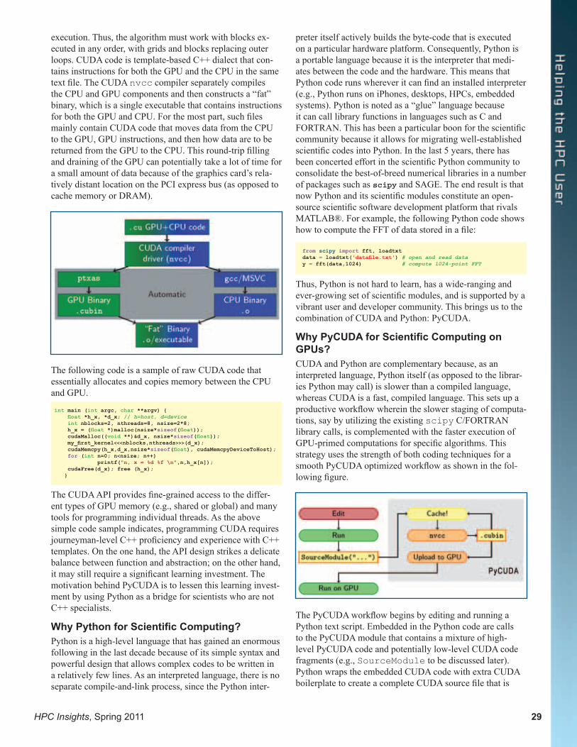
HPC Insights, Spring 2011 29
execution. Thus, the algorithm must work with blocks ex-ecuted in any order, with grids and blocks replacing outer loops. CUDA code is template-based C++ dialect that con-tains instructions for both the GPU and the CPU in the same text file. The CUDA nvcc compiler separately compiles the CPU and GPU components and then constructs a “fat” binary, which is a single executable that contains instructions for both the GPU and CPU. For the most part, such files mainly contain CUDA code that moves data from the CPU to the GPU, GPU instructions, and then how data are to be returned from the GPU to the CPU. This round-trip filling and draining of the GPU can potentially take a lot of time for a small amount of data because of the graphics card’s rela-tively distant location on the PCI express bus (as opposed to cache memory or DRAM).
The following code is a sample of raw CUDA code that essentially allocates and copies memory between the CPU and GPU.
The CUDA API provides fine-grained access to the differ-ent types of GPU memory (e.g., shared or global) and many tools for programming individual threads. As the above simple code sample indicates, programming CUDA requires journeyman-level C++ proficiency and experience with C++ templates. On the one hand, the API design strikes a delicate balance between function and abstraction; on the other hand, it may still require a significant learning investment. The motivation behind PyCUDA is to lessen this learning invest-ment by using Python as a bridge for scientists who are not C++ specialists.
Why Python for Scientific Computing?Python is a high-level language that has gained an enormous following in the last decade because of its simple syntax and powerful design that allows complex codes to be written in a relatively few lines. As an interpreted language, there is no separate compile-and-link process, since the Python inter-
preter itself actively builds the byte-code that is executed on a particular hardware platform. Consequently, Python is a portable language because it is the interpreter that medi-ates between the code and the hardware. This means that Python code runs wherever it can find an installed interpreter (e.g., Python runs on iPhones, desktops, HPCs, embedded systems). Python is noted as a “glue” language because it can call library functions in languages such as C and FORTRAN. This has been a particular boon for the scientific community because it allows for migrating well-established scientific codes into Python. In the last 5 years, there has been concerted effort in the scientific Python community to consolidate the best-of-breed numerical libraries in a number of packages such as scipy and SAGE. The end result is that now Python and its scientific modules constitute an open-source scientific software development platform that rivals MATLAB®. For example, the following Python code shows how to compute the FFT of data stored in a file:
Thus, Python is not hard to learn, has a wide-ranging and ever-growing set of scientific modules, and is supported by a vibrant user and developer community. This brings us to the combination of CUDA and Python: PyCUDA.
Why PyCUDA for Scientific Computing on GPUs?CUDA and Python are complementary because, as an interpreted language, Python itself (as opposed to the librar-ies Python may call) is slower than a compiled language, whereas CUDA is a fast, compiled language. This sets up a productive workflow wherein the slower staging of computa-tions, say by utilizing the existing scipy C/FORTRAN library calls, is complemented with the faster execution of GPU-primed computations for specific algorithms. This strategy uses the strength of both coding techniques for a smooth PyCUDA optimized workflow as shown in the fol-lowing figure.
The PyCUDA workflow begins by editing and running a Python text script. Embedded in the Python code are calls to the PyCUDA module that contains a mixture of high-level PyCUDA code and potentially low-level CUDA code fragments (e.g., SourceModule to be discussed later). Python wraps the embedded CUDA code with extra CUDA boilerplate to create a complete CUDA source file that is
int main (int argc, char **argv) { float *h_x, *d_x; // h=host, d=device int nblocks=2, nthreads=8, nsize=2*8; h_x = (float *)malloc(nsize*sizeof(float)); cudaMalloc((void **)&d_x, nsize*sizeof(float)); my_first_kernel<<<nblocks,nthreads>>>(d_x); cudaMemcpy(h_x,d_x,nsize*sizeof(float), cudaMemcpyDeviceToHost); for (int n=0; n<nsize; n++) printf("n, x = %d %f \n",n,h_x[n]); cudaFree(d_x); free (h_x); }
from scipy import fft, loadtxtdata = loadtxt('datafile.txt') # open and read datay = fft(data,1024) # compute 1024-point FFT
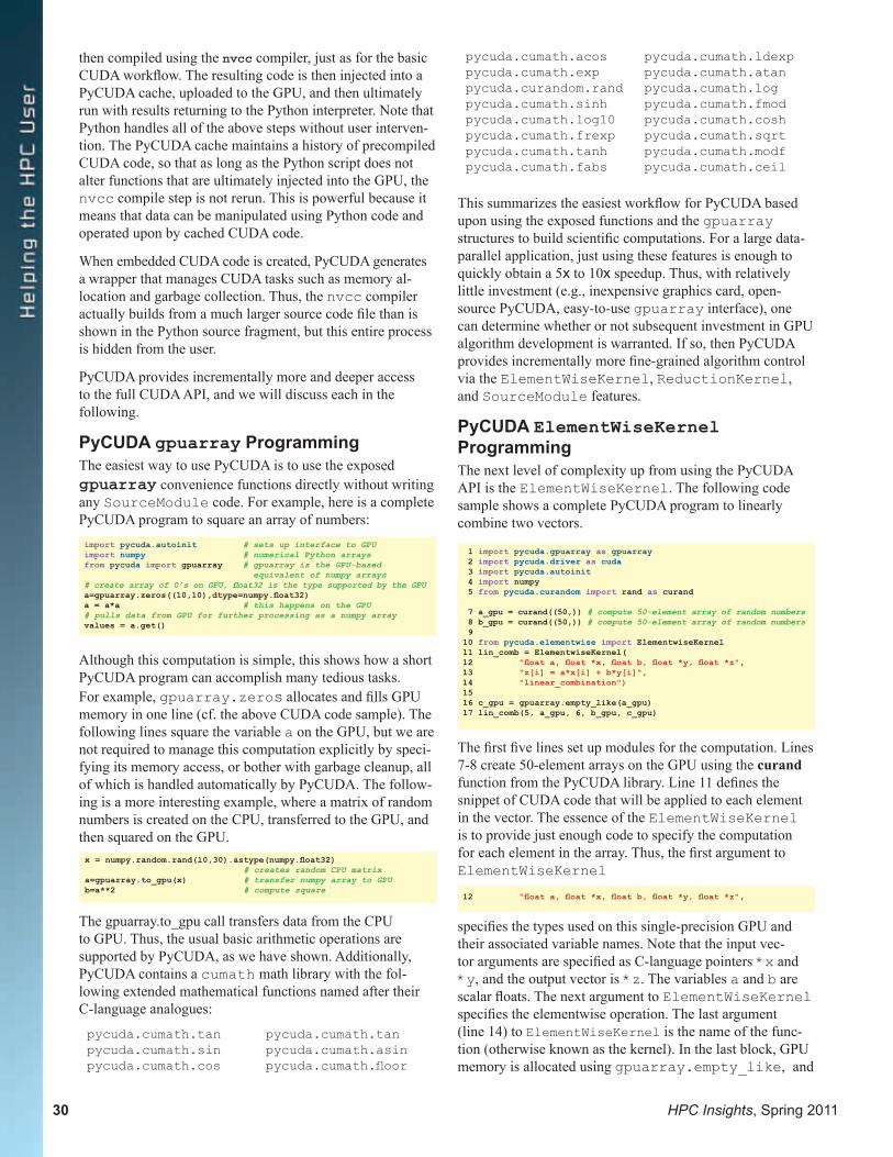
30 HPC Insights, Spring 2011
then compiled using the nvcc compiler, just as for the basic CUDA workflow. The resulting code is then injected into a PyCUDA cache, uploaded to the GPU, and then ultimately run with results returning to the Python interpreter. Note that Python handles all of the above steps without user interven-tion. The PyCUDA cache maintains a history of precompiled CUDA code, so that as long as the Python script does not alter functions that are ultimately injected into the GPU, the nvcc compile step is not rerun. This is powerful because it means that data can be manipulated using Python code and operated upon by cached CUDA code.
When embedded CUDA code is created, PyCUDA generates a wrapper that manages CUDA tasks such as memory al-location and garbage collection. Thus, the nvcc compiler actually builds from a much larger source code file than is shown in the Python source fragment, but this entire process is hidden from the user.
PyCUDA provides incrementally more and deeper access to the full CUDA API, and we will discuss each in the following.
PyCUDA gpuarray ProgrammingThe easiest way to use PyCUDA is to use the exposed gpuarray convenience functions directly without writing any SourceModule code. For example, here is a complete PyCUDA program to square an array of numbers:
Although this computation is simple, this shows how a short PyCUDA program can accomplish many tedious tasks. For example, gpuarray.zeros allocates and fills GPU memory in one line (cf. the above CUDA code sample). The following lines square the variable a on the GPU, but we are not required to manage this computation explicitly by speci-fying its memory access, or bother with garbage cleanup, all of which is handled automatically by PyCUDA. The follow-ing is a more interesting example, where a matrix of random numbers is created on the CPU, transferred to the GPU, and then squared on the GPU.
The gpuarray.to_gpu call transfers data from the CPU to GPU. Thus, the usual basic arithmetic operations are supported by PyCUDA, as we have shown. Additionally, PyCUDA contains a cumath math library with the fol-lowing extended mathematical functions named after their C-language analogues:
pycuda.cumath.tan pycuda.cumath.tanpycuda.cumath.sin pycuda.cumath.asinpycuda.cumath.cos pycuda.cumath.floor
pycuda.cumath.acos pycuda.cumath.ldexppycuda.cumath.exp pycuda.cumath.atanpycuda.curandom.rand pycuda.cumath.logpycuda.cumath.sinh pycuda.cumath.fmodpycuda.cumath.log10 pycuda.cumath.coshpycuda.cumath.frexp pycuda.cumath.sqrtpycuda.cumath.tanh pycuda.cumath.modfpycuda.cumath.fabs pycuda.cumath.ceil
This summarizes the easiest workflow for PyCUDA based upon using the exposed functions and the gpuarray structures to build scientific computations. For a large data-parallel application, just using these features is enough to quickly obtain a 5x to 10x speedup. Thus, with relatively little investment (e.g., inexpensive graphics card, open-source PyCUDA, easy-to-use gpuarray interface), one can determine whether or not subsequent investment in GPU algorithm development is warranted. If so, then PyCUDA provides incrementally more fine-grained algorithm control via the ElementWiseKernel, ReductionKernel, and SourceModule features.
PyCUDA ElementWiseKernel ProgrammingThe next level of complexity up from using the PyCUDA API is the ElementWiseKernel. The following code sample shows a complete PyCUDA program to linearly combine two vectors.
The first five lines set up modules for the computation. Lines 7-8 create 50-element arrays on the GPU using the curand function from the PyCUDA library. Line 11 defines the snippet of CUDA code that will be applied to each element in the vector. The essence of the ElementWiseKernel is to provide just enough code to specify the computation for each element in the array. Thus, the first argument to ElementWiseKernel
specifies the types used on this single-precision GPU and their associated variable names. Note that the input vec-tor arguments are specified as C-language pointers *x and *y, and the output vector is *z. The variables a and b are scalar floats. The next argument to ElementWiseKernel specifies the elementwise operation. The last argument (line 14) to ElementWiseKernel is the name of the func-tion (otherwise known as the kernel). In the last block, GPU memory is allocated using gpuarray.empty_like, and
import pycuda.autoinit # sets up interface to GPUimport numpy # numerical Python arraysfrom pycuda import gpuarray # gpuarray is the GPU-based equivalent of numpy arrays# create array of 0’s on GPU, float32 is the type supported by the GPUa=gpuarray.zeros((10,10),dtype=numpy.float32)a = a*a # this happens on the GPU# pulls data from GPU for further processing as a numpy arrayvalues = a.get()
x = numpy.random.rand(l0,30).astype(numpy.float32) # creates random CPU matrixa=gpuarray.to_gpu(x) # transfer numpy array to GPUb=a**2 # compute square
1 import pycuda.gpuarray as gpuarray 2 import pycuda.driver as cuda 3 import pycuda.autoinit 4 import numpy 5 from pycuda.curandom import rand as curand
7 a_gpu = curand((50,)) # compute 50-element array of random numbers 8 b_gpu = curand((50,)) # compute 50-element array of random numbers 910 from pycuda.elementwise import ElementwiseKernel11 lin_comb = ElementwiseKernel(12 "float a, float *x, float b, float *y, float *z",13 "z[i] = a*x[i] + b*y[i]",14 "linear_combination")1516 c_gpu = gpuarray.empty_like(a_gpu)17 lin_comb(5, a_gpu, 6, b_gpu, c_gpu)
12 "float a, float *x, float b, float *y, float *z",
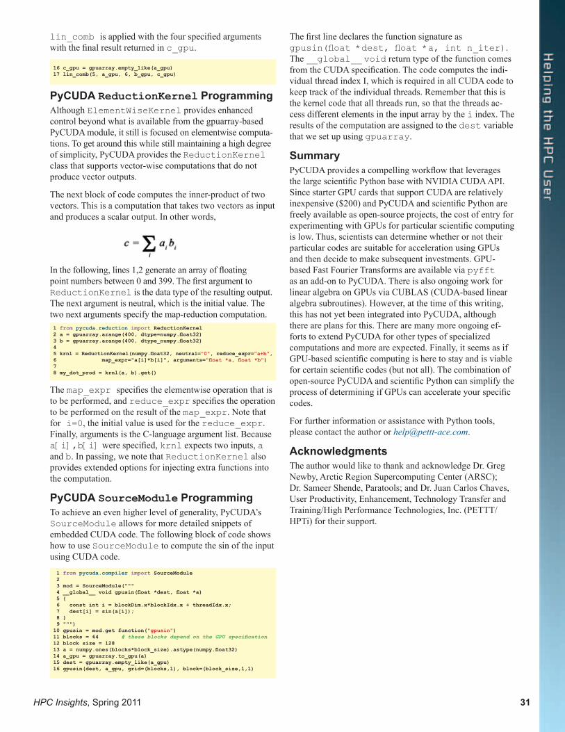
HPC Insights, Spring 2011 31
lin_comb is applied with the four specified arguments with the final result returned in c_gpu.
PyCUDA ReductionKernel ProgrammingAlthough ElementWiseKernel provides enhanced control beyond what is available from the gpuarray-based PyCUDA module, it still is focused on elementwise computa-tions. To get around this while still maintaining a high degree of simplicity, PyCUDA provides the ReductionKernel class that supports vector-wise computations that do not produce vector outputs.
The next block of code computes the inner-product of two vectors. This is a computation that takes two vectors as input and produces a scalar output. In other words,
In the following, lines 1,2 generate an array of floating point numbers between 0 and 399. The first argument to ReductionKernel is the data type of the resulting output. The next argument is neutral, which is the initial value. The two next arguments specify the map-reduction computation.
The map_expr specifies the elementwise operation that is to be performed, and reduce_expr specifies the operation to be performed on the result of the map_expr. Note that for i=0, the initial value is used for the reduce_expr. Finally, arguments is the C-language argument list. Because a[i],b[i] were specified, krnl expects two inputs, a and b. In passing, we note that ReductionKernel also provides extended options for injecting extra functions into the computation.
PyCUDA SourceModule ProgrammingTo achieve an even higher level of generality, PyCUDA’s SourceModule allows for more detailed snippets of embedded CUDA code. The following block of code shows how to use SourceModule to compute the sin of the input using CUDA code.
The first line declares the function signature as gpusin(float *dest, float *a, int n_iter). The __global__ void return type of the function comes from the CUDA specification. The code computes the indi-vidual thread index I, which is required in all CUDA code to keep track of the individual threads. Remember that this is the kernel code that all threads run, so that the threads ac-cess different elements in the input array by the i index. The results of the computation are assigned to the dest variable that we set up using gpuarray.
SummaryPyCUDA provides a compelling workflow that leverages the large scientific Python base with NVIDIA CUDA API. Since starter GPU cards that support CUDA are relatively inexpensive ($200) and PyCUDA and scientific Python are freely available as open-source projects, the cost of entry for experimenting with GPUs for particular scientific computing is low. Thus, scientists can determine whether or not their particular codes are suitable for acceleration using GPUs and then decide to make subsequent investments. GPU-based Fast Fourier Transforms are available via pyfft as an add-on to PyCUDA. There is also ongoing work for linear algebra on GPUs via CUBLAS (CUDA-based linear algebra subroutines). However, at the time of this writing, this has not yet been integrated into PyCUDA, although there are plans for this. There are many more ongoing ef-forts to extend PyCUDA for other types of specialized computations and more are expected. Finally, it seems as if GPU-based scientific computing is here to stay and is viable for certain scientific codes (but not all). The combination of open-source PyCUDA and scientific Python can simplify the process of determining if GPUs can accelerate your specific codes.
For further information or assistance with Python tools, please contact the author or [email protected].
AcknowledgmentsThe author would like to thank and acknowledge Dr. Greg Newby, Arctic Region Supercomputing Center (ARSC); Dr. Sameer Shende, Paratools; and Dr. Juan Carlos Chaves, User Productivity, Enhancement, Technology Transfer and Training/High Performance Technologies, Inc. (PETTT/HPTi) for their support.
16 c_gpu = gpuarray.empty_like(a_gpu)17 lin_comb(5, a_gpu, 6, b_gpu, c_gpu)
1 from pycuda.reduction import ReductionKernel2 a = gpuarray.arange(400, dtype=numpy.float32)3 b = gpuarray.arange(400, dtype_numpy.float32)45 krnl = ReductionKernel(numpy.float32, neutral="0", reduce_expr="a+b",6 map_expr="a[i]*b[i]", arguments="float *a, float *b")7 8 my_dot_prod = krnl(a, b).get()
1 from pycuda.compiler import SourceModule 2 3 mod = SourceModule(""" 4 __global__ void gpusin(float *dest, float *a) 5 { 6 const int i = blockDim.x*blockIdx.x + threadIdx.x; 7 dest[i] = sin(a[i]); 8 } 9 """)10 gpusin = mod.get function("gpusin")11 blocks = 64 # these blocks depend on the GPU specification12 block size = 12813 a = numpy.ones(blocks*block_size).astype(numpy.float32)14 a_gpu = gpuarray.to_gpu(a)15 dest = gpuarray.empty_like(a_gpu)16 gpusin(dest, a_gpu, grid=(blocks,1), block=(block_size,1,1)

32 HPC Insights, Spring 2011
IntroductionThe High Performance Computing Modernization Program (HPCMP) Technology Insertion (TI) process, while retaining much in common with previous years, has introduced some distinct changes in the 2011/2012 acquisition cycle. Perhaps most importantly, the TI process has gone from being on an annual cycle synchronized with the Federal fiscal year to a biennial cycle. This has provided an opportunity to evaluate the benchmark methodology, the applications composing the HPCMP benchmarking suite, the representativeness of the benchmarking test cases and how they relate to current and near-term future work, and a thorough revision of the formal rules under which vendor benchmarking should occur. This comprehensive rethinking of the benchmarking aspects of the HPCMP acquisition process has led to significant changes in how the machines are acquired while preserving many common characteristics with past efforts. This article compares current benchmarking work with legacy practices.
We discuss how this year’s benchmarking suite was constructed, with a goal of widening the selection of ap-plications over past years. The test cases as well were recon-sidered for representativeness as metrics for research-grade HPC work. The DoD standard machine was reevaluated, and a newer machine was chosen, replacing the long-held reference system. Old machines were removed from the
Everything You Ever Wanted to Know About the HPCMP TI-11/12 Benchmarking Process but Were Afraid to AskMark Cowan, Dr. Paul Bennett, Laura Brown, Carrie Leach, and Mahbubur Rashid, U.S. Army Engineer Research and Development Center DoD Supercomputing Resource Center, Vicksburg, Mississippi
list of systems under test, and newer ones were added to the HPCMP collection. The set of installed machines to be benchmarked was updated to ensure a wide variety of hardware and software for testing the benchmark suite. The consequences of these changes are explored below.
HPCMP Benchmarking Team The HPCMP benchmarking team, under the direction of the HPCMP Office (HPCMPO), consists of representatives from the HPCMPO, all five DSRCs, Instrumental, Inc., PMaC Laboratories, Inc., and the Computational Science & Engineering (CS&E) group at ERDC. Although widely dispersed geographically, all benchmarking team members have access to DoD HPC platforms at the U.S. Air Force Research Laboratory at Wright-Patterson AFB, Ohio (AFRL DSRC), the U.S. Army Research Laboratory at Aberdeen Proving Ground, Maryland (ARL DSRC), the U.S. Army Engineer Research and Development Center at Vicksburg, Mississippi (ERDC DSRC), the Navy DoD Supercomputing Resource Center at Stennis Space Center, Mississippi (Navy DSRC), and finally the Maui High Performance Computing Center at Kihei, Maui, Hawaii (MHPCC DSRC).
While the team is deeply involved in quantifying performance aspects for future acquisitions, another responsibility is to monitor and assess performance on current computational
HPC Insights, Spring 2011 33
platforms to determine quantitatively the consequences of hardware/software upgrades and administrative changes over the life of the machines. Although this aspect of the work is not the focus of this article, it is stated to suggest the level of familiarity that the team has with the benchmarked platforms and against which the vendor offerings are compared in the TI acquisition process.
Background on the Technology Insertion (TI) ProcessPrevious Technology Insertion (TI) cycles were performed on a yearly basis with roughly half of the DSRCs receiving major upgrades in a given year and the other DSRCs receiv-ing major upgrades in the following year. However, with our latest effort, it was decided that we should go to a 2-year cycle. Why the radical change in the way business is done?
The change was motivated by several issues, of which two or three are described here. Probably foremost among them is the desire to entice more vendors into the competition with a bigger pot of money. The HPCMP budget for new machines has remained fairly stable over the years, varying five to seven percent at times. By leveraging hardware ad-vances effectively, the HPCMP has been able to make great strides in getting significantly faster machines, often with new “leading-edge” technologies, at nearly the same nomi-nal dollar cost year after year. That, of course, is good for users and taxpayers. However, the number of participating vendors decreased over time. The competition was for the same amount year after year against six or seven competitors for one award, while the computational requirements went up. Among disincentives, preparing proposals and meet-ing benchmarking requirements can be a heavy burden in comparison to the compensation for the win, given aspects of the maintenance award structure. Some components of the acquisition process may have been deemed by some vendor management teams as inducing high risk in their offerings. Some industry leaders calculated the cost of their participa-tion and decided to sit it out, rather than compete. By com-bining the awards for 2 years’ worth of machine acquisitions, the HPCMP has tried to improve the business opportunity to entice inactive past participants back to the table.
As a positive side-effect of combining 2 years’ worth of acquisitions into one process, time was made available to review the entirety of TI acquisition, starting with a line-by-line justification of the benchmarking rules document by which the vendors’ offerings are evaluated, and ending with a comprehensive reevaluation of how we benchmark. Moving to a 2-year cycle provided us with more time to analyze the codes, determine if there were significant redun-dancies in the functionality being exercised by the test cases, ascertain where the holes in the benchmarking package were, and to establish a workable strategy to fill these holes and build a stronger benchmarking suite. At the conclusion of the current acquisition cycle, there will be more time to learn deeper intricacies of the codes, sharpening our analyti-cal tools in the process.
What about the disadvantages of a 2-year TI cycle? First, changing to a biennial cycle runs the risk of missing out on a new technology offering because of a poor choice of scheduling. Were we to time the milestones of the acquisi-tion schedule haphazardly, the HPC users may be provided non-optimal systems for 2 years instead of 1. As an example, if the proposals were due in February 2011 and a vendor choice made in, say, July, it is possible the Program could miss out on a new generation of processors. However, this remains a difficult problem: how can the Program schedule its activities so as to maximize the likelihood of hitting the pub-licly available products months in advance, while being blind to chip fabrication schedules and unforeseen recalls? This is simply not possible; no one has that kind of foresight. By cooperating with vendors as a group, adjustments can be made to the schedule advantageous to both vendor and the HPCMP.
For years, vendors have complained about the risk they are assuming to make their offerings. Some have reported that they have done all of the work associated with the TI pro-posal only to have it nixed at the last minute by their man-agement teams because of hard and fast rules associated with maintenance fees and other risk calculations. Assembling a proposal is not a cheap exercise—the structure of the offer-ing may require investment of hundreds of man-hours. To toss it all aside without competing is undoubtedly a difficult and expensive decision. In light of this, the TI-11/12 rules document was constructed with an eye toward addressing both vendor and HPC user community concerns. There was no desire to be seen as being punitive in terms of how the maintenance contract was awarded, but there were also cases in the past where one or more vendors may have appeared to stretch some of the rules to the point of breaking the spirit of what was desired. Attempts were made to rectify both of these problems with the updated benchmarking rules. Surprisingly, there have been times when the “semantics stretching” by vendors was deemed advantageous to the Government’s efforts at obtaining and maintaining a power-ful HPC platform—in these cases, the rules were reworded to make explicit to all what some vendors had only assumed in the past. One should compare the TI-10 with the TI-11/12 rules documents to see the full extent of the major overhauls and the minor tweaks.
How the Benchmarking Suite Is Chosen In the evaluation of the TI-10 benchmarking codes and test problems, the team was directed to analyze a much wider sample of HPC applications as pulled from HPCMP data-bases related to current usage and future requested allocation time. A couple of questions loomed large in these queries: Who is using the HPC cycles now? Who anticipates ac-celerating their usage over the next 2 to 3 years? Initially, 36 applications were in the first group of candidate applica-tions for the TI-11/12 suite. Various considerations, such as the current and future anticipated usage of the applications (both in unclassified and classified computing environ-ments), the ease of obtaining the source code, and the avail-ability of representative test cases, were used to reduce this
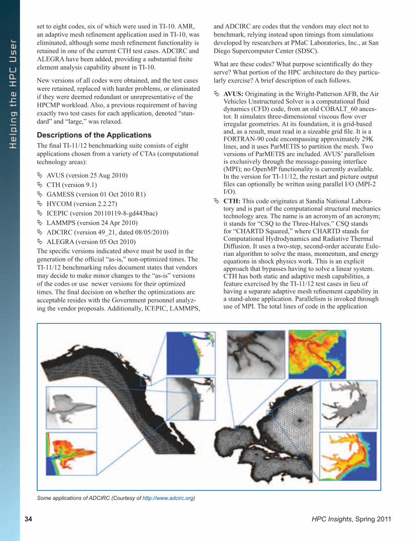
34 HPC Insights, Spring 2011
set to eight codes, six of which were used in TI-10. AMR, an adaptive mesh refinement application used in TI-10, was eliminated, although some mesh refinement functionality is retained in one of the current CTH test cases. ADCIRC and ALEGRA have been added, providing a substantial finite element analysis capability absent in TI-10.
New versions of all codes were obtained, and the test cases were retained, replaced with harder problems, or eliminated if they were deemed redundant or unrepresentative of the HPCMP workload. Also, a previous requirement of having exactly two test cases for each application, denoted “stan-dard” and “large,” was relaxed.
Descriptions of the ApplicationsThe final TI-11/12 benchmarking suite consists of eight applications chosen from a variety of CTAs (computational technology areas):
ª AVUS (version 25 Aug 2010) ª CTH (version 9.1) ª GAMESS (version 01 Oct 2010 R1) ª HYCOM (version 2.2.27) ª ICEPIC (version 20110119-8-gd443bac) ª LAMMPS (version 24 Apr 2010) ª ADCIRC (version 49_21, dated 08/05/2010) ª ALEGRA (version 05 Oct 2010)
The specific versions indicated above must be used in the generation of the official “as-is,” non-optimized times. The TI-11/12 benchmarking rules document states that vendors may decide to make minor changes to the “as-is” versions of the codes or use newer versions for their optimized times. The final decision on whether the optimizations are acceptable resides with the Government personnel analyz-ing the vendor proposals. Additionally, ICEPIC, LAMMPS,
and ADCIRC are codes that the vendors may elect not to benchmark, relying instead upon timings from simulations developed by researchers at PMaC Laboratories, Inc., at San Diego Supercomputer Center (SDSC).
What are these codes? What purpose scientifically do they serve? What portion of the HPC architecture do they particu-larly exercise? A brief description of each follows.
ª AVUS: Originating in the Wright-Patterson AFB, the Air Vehicles Unstructured Solver is a computational fluid dynamics (CFD) code, from an old COBALT_60 ances-tor. It simulates three-dimensional viscous flow over irregular geometries. At its foundation, it is grid-based and, as a result, must read in a sizeable grid file. It is a FORTRAN-90 code encompassing approximately 29K lines, and it uses ParMETIS to partition the mesh. Two versions of ParMETIS are included. AVUS’ parallelism is exclusively through the message-passing interface (MPI); no OpenMP functionality is currently available. In the version for TI-11/12, the restart and picture output files can optionally be written using parallel I/O (MPI-2 I/O).
ª CTH: This code originates at Sandia National Labora-tory and is part of the computational structural mechanics technology area. The name is an acronym of an acronym; it stands for “CSQ to the Three-Halves.” CSQ stands for “CHARTD Squared,” where CHARTD stands for Computational Hydrodynamics and Radiative Thermal Diffusion. It uses a two-step, second-order accurate Eule-rian algorithm to solve the mass, momentum, and energy equations in shock physics work. This is an explicit approach that bypasses having to solve a linear system. CTH has both static and adaptive mesh capabilities, a feature exercised by the TI-11/12 test cases in lieu of having a separate adaptive mesh refinement capability in a stand-alone application. Parallelism is invoked through use of MPI. The total lines of code in the application
Some applications of ADCIRC (Courtesy of http://www.adcirc.org)
HPC Insights, Spring 2011 35
number around 900K, of which 58 percent is FORTRAN and the remaining 42 percent C. CTH requires use of NetCDF, which is supplied with the TI-11/12 distribution.
ª GAMESS: The General Atomic and Molecular Structure System originates with the Gordon group at Iowa State University. It has been a mainstay in the TI process for years, in part because of its memory-intensive nature. The application falls under the aegis of the computational chemistry, biology, and material science technology area. As an ab initio quantum chemistry code, it computes many integrals with molecular data in the form of atom positions and electron orbitals. It can be compiled with LAPI, sockets, SHMEM, and MPI, although recent ver-sions have been focusing attention more toward MPI and away from LAPI. It is written almost entirely, 99 percent, in FORTRAN, while the remaining one percent, in the communication layer, is C-based.
ª HYCOM: Standing for the HYbrid Ocean Coordinate Model, this code comes from Dr. Alan Wallcraft of the U.S. Naval Research Laboratory. It falls under the climate/weather/ocean modeling and simulation compu-tational technology area. Coded 100 percent in FOR-TRAN, it is a primitive equation ocean general circula-tion model. As with AVUS, MPI-2 parallel I/O process-ing is available for processing large binary files.
ª ICEPIC: This application originates with Dr. Matthew Bettencourt of the Air Force Research Laboratory at Kirt-land AFB outside of Albuquerque, New Mexico. It serves as a representative of the computational electromagnetic and acoustics technology area. Described as a particle-in-cell plasma physics code, it is used widely in the design of electromagnetic devices. Ions and electrons are known to move under the influence of electromagnetic fields. In ICEPIC, the particles are updated in a grid-free manner and are grouped into cells that periodically are adjusted to preserve computational load balance. The fields are calculated on a structured, static grid and dual grid according to Maxwell’s equations. As a 100 percent C/C++ code, ICEPIC can simulate plasmas contained within complex geometries.
ª LAMMPS: As an application from Sandia National Laboratory, LAMMPS, like GAMESS, goes into the computational chemistry, biology, and material science technology area. It is a classical molecular dynamics code that models particles in a solid, liquid, or gaseous state. It calculates atomic velocities, positions, system energy, and temperature. All actions occur within a box that is usually orthogonal. Distributed-memory message-passing parallelism is accomplished by use of MPI. It is written in C++ and is portable. A fast Fourier transform library, such as FFTW, is necessary to compile the code. Recent code development has worked toward enabling usage of GPGPUs via CUDA.
The applications new to the TI process are ADCIRC and ALEGRA.
ª ADCIRC: Obtained from the University of North Carolina, Institute of Marine Sciences, ADCIRC is a coastal circulation and storm surge model. It solves time-dependent, free surface circulation and transport problems in two and three dimensions. It uses the finite element method (FEM) in space, permitting highly
flexible, unstructured grids. Typical ADCIRC uses have included modeling tides and wind-driven circulation, the analysis of hurricane storm surge and flooding, determin-ing dredging feasibility and material disposal studies, larval transport studies, and near-short marine operations. ADCIRC solves the equations of motion for a moving fluid on a rotating earth. These equations are formulated using the traditional hydrostatic pressure and Boussinesq approximations and have been discretized in space using the finite element (FE) method and in time using the finite difference (FD) method. ADCIRC can be run either as a two-dimensional depth integrated (2DDI) model or as a three-dimensional (3-D) model. In either case, elevation is obtained from the solution of the depth-integrated continuity equation in Generalized Wave-Continuity Equation (GWCE) form. Velocity is obtained from the solution of either the 2DDI or 3-D momentum equations. All of the nonlinear terms have been carefully retained in all of these equations. ADCIRC can be run using either a Cartesian or a spheri-cal coordinate system. It includes a least squares analysis routine that computes harmonic constituents for elevation and depth-averaged velocity during the course of the run, thereby avoiding the need to write out long time series for postprocessing. ADCIRC has been optimized by unrolling loops for en-hanced performance on multiple computer architectures. It includes MPI library calls to allow it to operate at high efficiency, typically better than 90 percent, on parallel computer architectures.
ª ALEGRA: Developed at Sandia National Laboratory, ALEGRA is an arbitrary Lagrangian-Eulerian code. The dual nature here provides flexibility, accuracy, and reduced numerical dissipation over a pure Eulerian code. Also advantageous, its modern remeshing technology allows for robust mesh smoothing and control.
Description of the Test Cases Previous TI cycles had required two test cases for each ap-plication, labeled “standard” and “large,” representing a typical run and a more demanding run, respectively. During review of the benchmarking process, it was found that this requirement should be relaxed since it led to redundancy for some codes and insufficient representation for other codes. To be representative of present and future usage, some appli-cations (e.g., HYCOM) need only a single test case.
On the other hand, an application’s capabilities may not be fully exercised with just two test problems. Such is the case with GAMESS, and the number of test cases was increased to three.
For the remaining applications, two test problems are still being used, although they are not named “standard” and “large,” and are not necessarily chosen to have moderate or large computational characteristics.
Another change was made in how many MPI processes are used to run the test cases. Formerly, the “standard” test case would be run across the same range of process counts (e.g.,

36 HPC Insights, Spring 2011
64, 128, 256, and 512) for every application and similarly for the “large” test case. For TI-11/12, it was decided to choose a set of process counts that was natural to the specific test case.
Descriptions of the test cases follow:
ª AVUS Waverider: This problem was used as the TI-10 “large” test case. It is a generic configuration for a super-sonic/hypersonic vehicle that “rides” a shock wave that forms below the vehicle at such speeds, i.e., the attached shock generates lift for the vehicle.
ª AVUS Turret-TD: This is a model of a turret in a wind tunnel. The turret has a number of small pins for control of the separation characteristics of the flow. Unlike previ-ous test cases, this one is a time-dependent variation. The grid file is read once at the beginning of the run, but both the restart and pix files are written out every 100 time-steps. Thus each file is written 10 times during the course of a 1000 time-step run. If AVUS is compiled in serial I/O mode, all I/O is done through one process that must collect all the pieces of the restart and pix files from all the other processes. Thus the time-dependent case is expected to scale poorly in serial I/O mode as the process count grows. If AVUS is compiled in parallel I/O mode, each process writes its own portion of the restart and pix files. For TI-11/12, the vendors are asked to provide benchmark times for runs using both serial and parallel I/O.
ª CTH Fixed-Grid: This model is a fixed-grid, long-rod penetrator with oblique impact. Specifically, a 7.67-cm-long, 0.767-cm-diameter rod made of 10 materials impacts a 0.64-cm-thick plate made of eight materials at an angle of 73.5 degrees. The initial velocity of the rod is 1210 m/s. The computation uses a 3-D fixed grid of 1840 × 230 × 460 cells and runs for 300 time-steps. A restart file, approximately 10 MB in size for each MPI process, is written at the beginning of the run and at the end of the run.
ª CTH AMR (Automatic Mesh Refinement): This case is the same as the TI-10 “standard” test case except that the maximum number of levels of refinement has been increased from six to eight, making the problem much more compute-intensive and memory-intensive than in TI-10. The model is for the same problem as described above for the fixed-grid test case, but the mesh is allowed to adaptively refine in areas in response to the intensity of the computation rather than use a uniform mesh over the entire domain. The number of time-steps is 200. A restart file for each MPI process is written at the begin-ning of the run and at the end of the run.
ª GAMESS MP2-grad: This test case performs a 2nd order Moller-Plasset computation that finds the
nuclear gradient vector of a “BC4” molecule (i.e., the [B(C(NO2)3)4]- oxygen-rich anion) using the restricted Hartree-Fock calculation with self-consistent field wave functions.
ª GAMESS DFT-grad: This test case performs a density functional theory computation to compute the nuclear gradient vector of a “POSS” molecule (i.e., the poly-hedral oligomeric silsesquioxane molecule) using the restricted Hartree-Fock calculation with self-consistent field wave functions.
ª GAMESS CC-energy (modified): The CC-energy test case is a “coupled cluster singles plus doubles plus a perturbative estimate of triples” energy calculation, denoted as CCSD(T), on an energetic heterocyclic ring compound.
ª HYCOM large: The sole HYCOM test case is a 32-layer, 1/25 degree global model that simulates 1 day. It requires approximately 1.8 GB of memory per proces-sor and about 180 GB of globally accessible scratch disk.
ª ICEPIC magnetron: This test case performs a simula-tion of a magnetron for a high-power microwave source during startup. It features many transient waves with particles representing electrons being created and mov-ing in a grid-free way throughout the domain. There are relatively fewer particles than in the larger gyrotron test case described below. This test case emphasizes wave simulation with finite difference time domain more so than the gyrotron test case; the particle-in-cell aspect is significantly less than in the other test case.
ª ICEPIC gyrotron: This test case is a big simulation of the gyrotron source of the air-borne version of the active denial system (ADS). While the mechanics of the up-dates of the particles and fields are similar to the smaller magnetron test described above, there are many more particles. Therefore, it must perform significantly more particle-in-cell (PIC) work than the other test case. In ef-fect, this test case tests the particle physics more than the magnetron case.
ª LAMMPS AU: This model contains a cluster of 121 functionalized gold nanoparticles. The gold nanoparticles are 5 nm in diameter and coated with alkanethiol ligands with eight carbons and a terminating methyl group. The ligands are simulated using the united atom method.
ª LAMMPS T160: This test case is a simulation of carbon nanotube bundles with interstitial carbon atom bonding. It uses 2,406,062 atoms and 10,000 time-steps. An input file contains specifications for the inter-atomic potentials.
ª ADCIRC Baroclinic: This test case simulates the dynamics of the Turkish Straits System, including the Northeastern Aegean Sea, Marmara Sea, and the south-west Black Sea. These seas are connected to each other by the Dardanelles and the Bosphorus straits, and the salinity/density differences in the seas create/govern a two-layer flow system in both straits. This case is com-posed of 310,435 nodes and 605,099 elements, and the maximum resolution of the model goes down to 20 m. Although this case is rather I/O intensive, it scales out to approximately 2K cores.
ª ADCIRC Hurricane: This ADCIRC case is for a Gulf of Mexico hurricane surge simulation. It represents a typical ADCIRC application that the U.S. Army Corps

HPC Insights, Spring 2011 37
of Engineers looks at when doing levee designs or flood plain mappings for FEMA. Within ADCIRC it is exercis-ing the wetting and drying algorithm, as well as the usual hydrodynamic solution for depth-averaged velocities and sea surface elevation. It has 2,734,399 nodes and 5,357,158 elements in its input decks.
ª ALEGRA Wire Explosion: This is a two-dimensional simulation of a suspended aluminum wire exploding. It is represented within a rectilinear-biased mesh in cylin-drical (r-z) geometry with 12.5 micrometer resolution (12.5 million elements), with the elapsed time at 1 micro-second.
ª ALEGRA Oblique Sphere Impact: This is a three-dimensional representation of the Grady-Kipp oblique sphere impact experiment, where a copper sphere of 3.18 mm radius hits a rectangular steel plate with a velocity of 4520 m/s at an angle of 30.8 degrees. The geometrical mesh is three-dimensional and rectilinear, with the problem having a resolution of 300 micrometers totaling 19.3 million elements. The elapsed time for this simulation is 15 microseconds.
For each test case, an accuracy check must be provided that objectively determines if a run has produced good results. The different numerical properties produced by computers employing different chips, compilers, optimization options, environment variables, and MPI implementations ensure that output files from runs on one computer are rarely identical to the output files from runs on another computer. For this reason, an accuracy check often consists of a “correct” out-put file, called a reference file, and one or more tolerances or error bounds by which a given output file can vary from the reference output file. For some applications, the developer of the test case can provide guidance on how to construct an accuracy check. The developer often provides scripts or suitable bounds for an output quantity against which a
Code Case DistProcTime (sec) on Diamond Core Counts
ADCIRC baroclinic 1024 13860 512, 768, 1024, 1280, 1536, 1792, 2048ADCIRC hurricane 1280 14160 512, 768, 1024, 1280, 1536, 1792, 2048ALEGRA obliqueImp 1536 2145 1024, 1280, 1536, 1792, 2048ALEGRA explWire 512 1469 256, 384, 512, 768, 1024AVUS waverider 1024 941 384, 512, 768, 1024, 1536AVUS turret-td 1280 1332 768, 1024, 1280, 1536, 2048CTH fixed-grid 1280 3507 768, 1024, 1280, 1536, 2048CTH amr 1280 2535 768, 1024, 1280, 1536, 2048GAMESS DFT-grad 256 4701 128, 192, 256, 384, 512GAMESS MP2-grad 512 2536 128, 256, 512, 768, 1024GAMESS CC-energy 1024 3658 512, 768, 1024, 1536, 2048HYCOM lrg 1353 3020 1001, 1353, 1516, 1770, 2045ICEPIC magnetron 384 2559 256, 384, 512, 768, 1024ICEPIC gyrotron 2048 3639 1536, 1792, 2048, 2304, 2560LAMMPS AU 1024 3182 128, 256, 384, 512, 1024, 1280, 1536, 2048LAMMPS T160 256 4073 64, 128, 256, 384, 512, 768, 1024, 1280
given output can be checked to quickly determine whether the results are good. For other applications, the error bounds are determined empirically by making runs across several platforms under various choices of compilers, optimization options, and MPI libraries. Then statistics are obtained, and reasonable error bounds are fixed. This is obviously a time-intensive process. The accuracy checks are provided as part of the TI-11/12 distribution to HPC vendors. A run cannot be accepted as valid unless the accuracy check is passed.
A summary of the codes, their test cases, the core counts over which the test cases are run, the distinguished processor count, and a time from the ERDC Diamond machine at that distinguished processor count is provided in the table below.
Code OptimizationFor TI-11/12, Diamond, an SGI Altix ICE platform at the ERDC DSRC, was chosen as the DoD standard, or refer-ence, system. The benchmark rules state that at least one of the vendor’s supplied times for each test case must beat the corresponding benchmark time on the DoD reference machine by a factor of two. Since Diamond is one of the newest and fastest of the installed HPCMP platforms, this is obviously a demanding requirement. However, the vendor is not limited to the process counts given in the table below. The vendor can use any process count to beat the time given for Diamond at the distinguished process count. However, if the application does not scale well above the distinguished process count, it may not help to use more processes. In that case, the vendor can attempt to use a newer version of the code or optimize the current version by using standard optimization techniques. These techniques may include loop unrolling, loop fission or fusion, loop blocking, compiler directives, calls to optimized vendor numerical libraries,
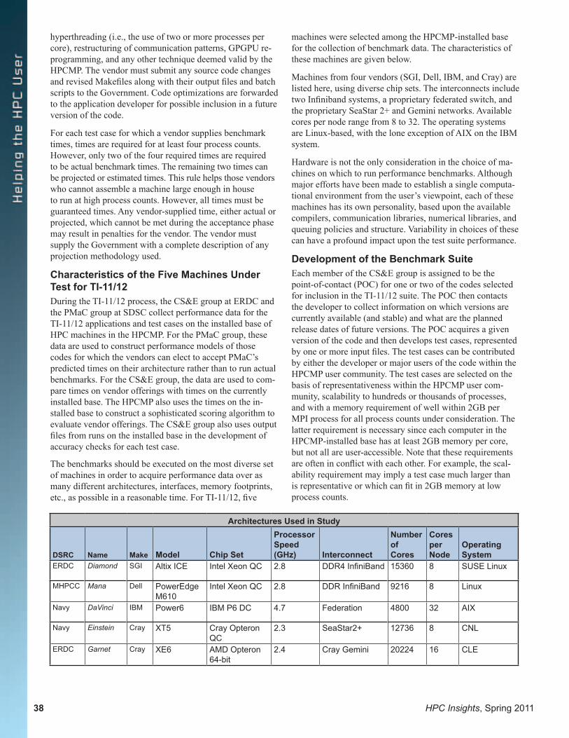
Architectures Used in Study
DSRC Name Make Model Chip Set
Processor Speed (GHz) Interconnect
Number of Cores
Cores per Node
Operating System
ERDC Diamond SGI Altix ICE Intel Xeon QC 2.8 DDR4 InfiniBand 15360 8 SUSE Linux
MHPCC Mana Dell PowerEdge M610
Intel Xeon QC 2.8 DDR InfiniBand 9216 8 Linux
Navy DaVinci IBM Power6 IBM P6 DC 4.7 Federation 4800 32 AIX
Navy Einstein Cray XT5 Cray Opteron QC
2.3 SeaStar2+ 12736 8 CNL
ERDC Garnet Cray XE6 AMD Opteron 64-bit
2.4 Cray Gemini 20224 16 CLE
38 HPC Insights, Spring 2011
hyperthreading (i.e., the use of two or more processes per core), restructuring of communication patterns, GPGPU re-programming, and any other technique deemed valid by the HPCMP. The vendor must submit any source code changes and revised Makefiles along with their output files and batch scripts to the Government. Code optimizations are forwarded to the application developer for possible inclusion in a future version of the code.
For each test case for which a vendor supplies benchmark times, times are required for at least four process counts. However, only two of the four required times are required to be actual benchmark times. The remaining two times can be projected or estimated times. This rule helps those vendors who cannot assemble a machine large enough in house to run at high process counts. However, all times must be guaranteed times. Any vendor-supplied time, either actual or projected, which cannot be met during the acceptance phase may result in penalties for the vendor. The vendor must supply the Government with a complete description of any projection methodology used.
Characteristics of the Five Machines Under Test for TI-11/12During the TI-11/12 process, the CS&E group at ERDC and the PMaC group at SDSC collect performance data for the TI-11/12 applications and test cases on the installed base of HPC machines in the HPCMP. For the PMaC group, these data are used to construct performance models of those codes for which the vendors can elect to accept PMaC’s predicted times on their architecture rather than to run actual benchmarks. For the CS&E group, the data are used to com-pare times on vendor offerings with times on the currently installed base. The HPCMP also uses the times on the in-stalled base to construct a sophisticated scoring algorithm to evaluate vendor offerings. The CS&E group also uses output files from runs on the installed base in the development of accuracy checks for each test case.
The benchmarks should be executed on the most diverse set of machines in order to acquire performance data over as many different architectures, interfaces, memory footprints, etc., as possible in a reasonable time. For TI-11/12, five
machines were selected among the HPCMP-installed base for the collection of benchmark data. The characteristics of these machines are given below.
Machines from four vendors (SGI, Dell, IBM, and Cray) are listed here, using diverse chip sets. The interconnects include two Infiniband systems, a proprietary federated switch, and the proprietary SeaStar 2+ and Gemini networks. Available cores per node range from 8 to 32. The operating systems are Linux-based, with the lone exception of AIX on the IBM system.
Hardware is not the only consideration in the choice of ma-chines on which to run performance benchmarks. Although major efforts have been made to establish a single computa-tional environment from the user’s viewpoint, each of these machines has its own personality, based upon the available compilers, communication libraries, numerical libraries, and queuing policies and structure. Variability in choices of these can have a profound impact upon the test suite performance.
Development of the Benchmark SuiteEach member of the CS&E group is assigned to be the point-of-contact (POC) for one or two of the codes selected for inclusion in the TI-11/12 suite. The POC then contacts the developer to collect information on which versions are currently available (and stable) and what are the planned release dates of future versions. The POC acquires a given version of the code and then develops test cases, represented by one or more input files. The test cases can be contributed by either the developer or major users of the code within the HPCMP user community. The test cases are selected on the basis of representativeness within the HPCMP user com-munity, scalability to hundreds or thousands of processes, and with a memory requirement of well within 2GB per MPI process for all process counts under consideration. The latter requirement is necessary since each computer in the HPCMP-installed base has at least 2GB memory per core, but not all are user-accessible. Note that these requirements are often in conflict with each other. For example, the scal-ability requirement may imply a test case much larger than is representative or which can fit in 2GB memory at low process counts.
Once the test cases are selected, the codes are ported to the five systems under test to be used in the TI-11/12 cycle. For each test case, a reference file, if needed, is generated on the DoD reference system (Diamond) or some other system in the HPCMP using an executable compiled at low or moderate optimization. The POC must be confident in the accuracy of the reference file. Using the reference file for comparison, the POC may be required to develop an empiri-cal accuracy test using error tolerances resulting from runs on other platforms or on the same platform using different compilers, optimization levels or other compiler options, process counts, environment variables, MPI or numerical libraries, and other variables.
Once the accuracy tests are developed, the POC writes a README file for his application describing how to compile the code, run the test cases, and evaluate the accuracy of the results. When the benchmark suite has been assembled and tested, the suite is released to the vendors via the official HPCMP TI-11/12 website. Deliverables to be returned to the Government by the vendor generally include any batch submission scripts, batch output files, other output files if used in the accuracy check, modified Makefiles or build scripts, and any source code that was modified for purposes of porting or optimization. Before submitting benchmark results, the vendor must submit the version of the code to be used to the Government as well as the cache structure of the proposed offering so that PMaC can develop their perfor-mance predictions.
The General Services Administration serves as a conduit of communication among the vendors, the HPCMP, and the benchmarking team. Occasionally, questions, problems, and requests for clarification may come from the vendors that must be resolved by the benchmarking team in consultation with the HPCMP.
Evaluation of Vendor Results Once the vendor proposals arrive, there is a limited time frame in which to make sense of what the vendors did and determine what they are offering. The first concern is whether they followed the rules. If not, their proposals must be deprecated, or discarded if bad enough. Secondly, is there anything unusual in the proposal? This is one of those “trust, but verify” situations. Sometimes the cause of differences between expected results and vendor results is apparent after a short investigation; at other times, considerable effort may be required to achieve resolution. Keys to all of this are considerations of the results that are being reported, and the evidence that is presented to confirm them. The vendor documentation is reviewed and, if necessary, the vendors are queried through the GSA representative for additional details to alleviate the benchmark team’s concerns.
From a benchmarker’s perspective, the essence of the proposals is vendor guaranteed performance. The vendor’s times are compared with the Government’s times, and the vendor’s optimizations are evaluated to determine whether they are of such a nature that an average HPC user would be
willing to modify the code in like manner to get similar per-formance improvement, or whether the developer is willing to incorporate the proposed changes into a future release of the code. Vendor optimizations are accepted upon a positive answer to either of these questions.
Globally, a great consideration is the determination of the characteristics of the machine upon which the benchmarks were executed, and how that machine compares with the of-fering. Sometimes a vendor will benchmark upon the same machine as being offered, smaller in the number of cores perhaps, but generally the same. At other times, a vendor will benchmark on a machine but offer a decidedly different one, with vast differences in chip architectures, communica-tion layout, and memory. How should one compare perfor-mance on such radically disparate machines? Consequently, how can one trust guarantees on the proposed system performance based upon runs from something so different? Does the vendor’s estimation methodology take into account all hardware differences between the benchmarked and the proposed machines? Are the differences bridgeable—that is, can the vendor reasonably be expected to assemble a system with the stated performance? The level of risk that the Government incurs by allowing performance numbers from one system to form the basis for guaranteed times on the proposed system is also considered. The benchmarking team investigates whether the offering is so technologically brilliant and innovative that it may be worth the risk, and the HPCMP decides to accept it or not. The full extent of the benchmark team’s investigations and considerations is presented to the HPCMP to warrant the quantification of proposal risk. At times, additional in-depth technical infor-mation can mean a modification in how the risk is assessed.
The evaluation of the vendor results is a long complex pro-cess during which many teams, including the Benchmarking Team, the Usability Team, the Performance Team, and the Collective Acquisition Team, look at the vendor proposals in depth. As one part of the evaluation process, the benchmark-ing team remains available for questions and research as needed by her sister components.
Status of the Current TI-11/12 Benchmarking Effort At the time of this writing, the status of the TI-11/12 bench-marking effort is as follows. All of the official versions of the codes have been acquired, and the test problems have been assembled. They have been tested on the five machines under test for this cycle. The performance has been charted in order to determine what more can be done to improve performance and scalability.
The official TI-11/12 benchmarking suite has been assem-bled and made available online for the vendors. The docu-mentation and READMEs for the codes are current, and occasionally questions are delivered to the benchmark team, through the GSA representative, asking for clarification or additional insight. The benchmark team’s response is passed back to the vendor community by the GSA. The current
HPC Insights, Spring 2011 39
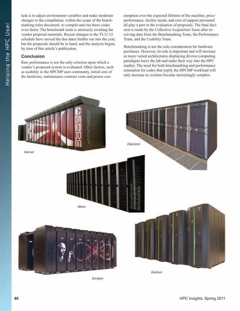
task is to adjust environment variables and make moderate changes to the compilation, within the scope of the bench-marking rules document, to compile and run these codes even faster. The benchmark team is anxiously awaiting the vendor proposal materials. Recent changes to the TI-11/12 schedule have moved the due dates further out into the year, but the proposals should be in hand, and the analysis begun, by time of this article’s publication.
ConclusionRaw performance is not the only criterion upon which a vendor’s proposed system is evaluated. Other factors, such as usability to the HPCMP user community, initial cost of the hardware, maintenance contract costs and power con-
sumption over the expected lifetime of the machine, price/performance, facility needs, and cost of support personnel all play a part in the evaluation of proposals. The final deci-sion is made by the Collective Acquisition Team after re-ceiving data from the Benchmarking Team, the Performance Team, and the Usability Team.
Benchmarking is not the sole consideration for hardware purchases. However, its role is important and will increase as more varied architectures displaying diverse computing paradigms leave the lab and make their way into the HPC market. The need for both benchmarking and performance estimation for codes that typify the HPCMP workload will only increase as systems become increasingly complex.
40 HPC Insights, Spring 2011
Garnet
Diamond
Einstein
DaVinci
Mana

HPC Insights, Spring 2011 41
The Sustained Systems Performance (SSP) test has been established to monitor the performance delivered by the High Performance Computing Modernization Program’s (HPCMP) high performance computing (HPC) systems. The tests are conducted by the HPCMP during the last month of each quar-ter. Additionally, the DoD Supercomputing Resource Centers (DSRCs) have been mandated by the Baseline Configuration Team to conduct the SSP test on their systems under test (SUT) in conjunction with certain events. These events include scheduled or unscheduled maintenance periods of updating the operating system, implementing security patches, and experiencing unexpected outages. At the discretion of each DSRC, the SSP test may also be conducted after up-grades to the compilers or numerical libraries, or after reboot cycles to clear unresponsive systems.
The codes used in the SSP benchmark suite for a given system are taken from the Application Benchmark Test Packages (ABTP) suite used to procure that system. As such, the ABTP codes and input test data approximate the workload on the SUT, thereby giving a general picture of the system’s perfor-mance from the user’s perspective. Each SSP suite is named following the ABTP suite from which it is derived. For exam-ple, SSP-07 uses codes and input test data from TI-07. Codes included in any SSP suite are chosen based upon proven migration capability and well-defined numerical checks, so as to minimize the effort required to compile the codes and test the results each quarter.
The SSP-07 suite is comprised of the Air Vehicles Unstructured Solver (AVUS), CSQ to the Three Halves (CTH), General Atomic and Molecular Electron Structure System (GAMESS), the HYbrid Coordinate Ocean Model (HYCOM), and an Out-Of-CORE (OOCORE) solver. Each code has two test cases, the so-called standard and large test cases. Each code is parallelized using MPI for communica-tions, although GAMESS can also use shmem, 1-sided MPI on IBM systems, and sockets under TCP/IP protocol. Additionally, HYCOM can use MPI, shmem, and OpenMPI to perform its computational tasks. The benchmarks are con-ducted at the distinguished core counts from TI-07, which is 64 for the AVUS, CTH, GAMESS, and OOCORE standard test cases and 384 for the large. However, the HYCOM standard test case executes at 59 cores, and the large test case executes at 385. The SSP-08 suite uses the same codes and similar test cases, but the distinguished core counts for its benchmarks are 128 for most standard test cases except HYCOM, which uses 124, and 512 for most large test cases, again except for HYCOM, which uses 504.
AVUS is used in computational fluid dynamics research to solve the compressible Euler and Navier-Stokes equations sub-ject to the ideal gas state equation using an implicit solver [1,2]. The equations are discretized on unstructured grids that are par-titioned using the Parallel Graph Partitioning and Fill-reducing Matrix Ordering (ParMETIS) library available from Karypis
HPCMP Sustained Systems Performance Test: What It Is and How It WorksDr. Paul M. Bennett, U.S. Army Engineer Research and Development Center DoD Supercomputing Resource Center, Vicksburg, Mississippi
Lab at the University of Minnesota. Most of AVUS is written in FORTRAN90, but one auxiliary library and ParMETIS are written in C. AVUS uses nonblocking communication to per-form point-to-point exchanges of messages. The standard test case simulates flow over a wind tunnel model of a wing with a flap and endplates. The model uses 7.3 million cells, requiring 500 MB in an IEEE binary grid. The large test case simulates a supersonic or hypersonic vehicle riding a shock wave that forms beneath the vehicle. The model uses 31 million cells. Both test cases run for 200 time-steps.
CTH is a family of codes developed by Sandia National Laboratory to model complex multidimensional problems arising in the study of objects assembled from multiple mate-rials subjected to large deformations and strong shocks. For this reason, it is used in computational structural mechanics. The particular code used for the benchmarks computes the physical models [3]. CTH is written in Fortran and C. Both test cases feature a rod comprised of 10 materials impact-ing a spinning plate made of 8 materials at an oblique angle. The standard test case uses an adaptive mesh refinement set to refine up to five levels and runs for 500 time-steps, but the large test case computes on a static grid and runs for 190 time-steps.
GAMESS is used in computational chemistry, biology, and materials. Its algorithms feature numerical quadrature rules applied to determine the electron shell structure of molecules resembling those of current interest to the DoD. The integrals are computed using analytic expressions and recursion for-mulae applied to a variety of basis functions that approximate the electron shells [4, 5]. After initially setting up the model, the integrals are computed using little or no communication. Results are assembled at the end using collective communica-tion calls. Much of the numerical heavy lifting is performed by calls to vendor libraries, such as ESSL on IBM systems, Cray’s libsci, or Intel’s MKL. The standard test case performs a restricted Hartree-Fock calculation using density functional theory to compute the nuclear gradient vector of a polyhedral oligometric silsesquioxane. The large test case also performs a restricted Hartree-Fock computation, but it uses a second-order Moller-Plesset correction method to compute the nuclear gradi-ent vector of an anion of a potent advanced chemical oxidizer. Both test cases employ self-consistent field wave equations to approximate the electron shells.
HYCOM is a climate/weather/ocean modeling code that uses a generalized hybrid vertical coordinate system that allows for smooth transitions between traditional isopycnic vertical coordinates in deep stratified water to coordinates that follow terrain in shallow coastal regions, and also to z-level coordi-nates in the mixed layer and unstratified ocean. It consists of 31000 lines of Fortran 90, and it is fully global and capable of resolving eddies. Laterally, HYCOM uses a conventional second-order finite-difference hydrostatic primitive ocean scheme. Vertically, HYCOM uses an arbitrary Lagrange

42 HPC Insights, Spring 2011
Eulerian coordinate system. The globe is tiled, and all tiles consisting solely of land are discarded. Each processor is assigned one tile, resulting in core counts that typically do not fully populate all cores of all the nodes used for processing HYCOM jobs. Point-to-point communication is performed by persistent calls to nonblocking sends and receives and calls to MPI_SENDRECV. The standard test case computes a 26-layer 1/4 degree global model for 24 hours, and the large test case computes a 26-layer 1/12 degree global model for 12 hours. More information on HYCOM may be found in [6].
OOCORE is the primary numerical kernel of an electro-magnetics code that may not be used in system acquisition or performance monitoring. As such, it belongs in the com-putational electromagnetic and acoustics family of codes. Its work is to solve a linear system of equations using an LU decomposition called from vendor implementations of the ScaLAPACK package available from the University of Tennessee at Knoxville. The standard test case is set to run the solver in in-core fashion, but the large test case runs in out-of-core fashion, forcing the SUT to open two files for each MPI process for file input/output. This places a strenuous demand upon the system that is useful to evaluate the strength of the systems file I/O capabilities at execution time. In contrast, the standard test case uses main memory to store the LU decom-position instead. The standard test case solves a linear system with 53,000 variables, and the large test case solves a system with 78,000 variables.
The codes in the SSP-08 are the same codes as in SSP-07, although at later revision levels in the cases of GAMESS, HYCOM, and OOCORE. The major differences between the two suites is in the core counts for SSP-08, being 128 for most standard test cases, 124 for the HYCOM standard test case, and 512 for most large test cases, with HYCOM large at 504. There are also differences in the input test data for AVUS, CTH, and OOCORE. The SSP-08 AVUS standard test case runs for 900 time-steps, and the large test case runs for 400 time-steps. Otherwise, the TI-08 AVUS test cases are the same as TI-07. The SSP-08 CTH standard test case runs for 600 time-steps, compared with 500 in SSP-07, and the SSP-08 CTH large test case runs for 400 time-steps compared with 190 in SSP-07. The TI-08 CTH test cases are otherwise the same as TI-07. The OOCORE standard test case solves a linear system with 62,000 variables, and the large test case solves a linear system with 82,000 variables.
In practice, the AVUS and OOCORE test cases in SSP-07 and SSP-08 were found to surface many of the same performance issues as GAMESS and HYCOM, so the SSP-09 suite has only CTH, GAMESS, and HYCOM. All three codes are at later revision levels than in SSP-08. There are two test cases each for CTH and HYCOM, but only the large test case for GAMESS, in order to monitor vendor-supplied numeri-cal libraries. Two synthetic benchmark tests were added to the suite, however. These are OSBENCH, which measures performance losses arising from jitter produced by the operat-ing system, and MultiMAPS, which measures the four data bandwidths between the central processing unit (CPU) and the three levels of data cache and main memory. OSBENCH is essentially the code P-SNAP authored at the Los Alamos
National Laboratory for the purpose of quantifying interfer-ence or noise by the operating system. MultiMAPS is de-veloped by the Performance Modeling and Characterization Institute at the San Diego Supercomputing Center. The distinguished core counts are 256 for CTH standard, 250 for HYCOM standard, 1024 for CTH and GAMESS large, and 1006 for HYCOM large. OSBENCH runs on 64 cores, and MultiMAPS runs on exactly 1. In SSP-09, the time-steps in the CTH standard test case were dialed back to 350 from 600. Similarly, the CTH large test case time-steps were dialed back to 300 from 400. The GAMESS test case is a second-order Moller-Plesset correction method, as in SSP-07 and -08, but it has a different basis and performs the computation for a dif-ferent molecule. The HYCOM standard test case is the same as in SSP-07 and SSP-08, but the large test case was revised to compute a 26-layer 1/12 degree model for 18 hours.
Although none of the codes and test cases used in SSP-09 changed from TI-09 to TI-10, the SSP-10 suite is not identical to the SSP-09 suite. The differences are that a later version of CTH is used, as that is what was used by Cray Inc. in ac-ceptance testing on the Cray XE6 systems now at ERDC and AFRL DSRCs. Additionally, the source codes for GAMESS and HYCOM were tuned by Cray Inc.
The SSP test plays an important role in monitoring the qual-ity of HPC service that the HPCMP delivers to DoD users program-wide. The test suites change from TI to TI to monitor the performance of the SUTs as their anticipated workloads change. The benchmark performance results are used by the system administrators of the SUTs, the DSRCs themselves, and the vendors to help evaluate the quality of HPC system updates and to perform corrective actions on the SUTs as necessary.
References[1] Tomaro, R.F., W.Z. Strang, and L.N. Sankar, “An Implicit Algo-rithm for Solving Time-Dependent Flows on Unstructured Grids,” AIAA 97-0333, 35th Aerospace Sciences Meeting and Exhibit, Reno, NV, Jan. 1997.[2] Schloegel, K., G. Karypis, and V. Kumar, “A Unified Algorithm for Load-balancing Adaptive Scientific Simulations.” Supercom-puting 2000.[3] Hertel, Jr., E.S., et al., “CTH: A Software Family for Multi-Dimensional Shock Physics Analysis.” Proceedings of the 19th In-ternational Symposium on Shock Waves, Marseilles, France, 26-30 July 1993, Volume 1, pp. 377-382.[4] Schmidt M.W., K.K. Baldridge, J.A. Boatz, S.T. Elbert, M.S. Gordon, J.H. Jensen, S. Koseki, N. Matsunaga, K.A. Nguyen, S.J. Su, T.L. Windus, M. Dupuis, and J.A. Montgomery, “General Atomic and Molecular Electronic Structure System.” J. Comput. Chem., 14, pp. 1347–1363, 1993. [5] Gordon, M.S. and M.W. Schmidt, “Advances in electronic structure theory: GAMESS a decade later.” Appearing in Theory and Applications of Computational Chemistry, the first forty years, eds. C.E. Dykstra, G. Frenking, K.S. Kim, and G.E. Scuseria, Else-vier, Amsterdam, 2005.[6] Bleck, R., “An Oceanic General Circulation Model Framed in Hybrid Isopycnic-Cartesian Coordinates.” Ocean Modeling, 4, pp. 55–88, 2002.

HPC Insights, Spring 2011 43
The Governor of the State of Louisiana, Bobby Jindal, pro-claimed November 14-19, 2010, as SUPERCOMPUTING WEEK in the State of Louisiana. In his proclamation, the Governor said “high-performance computing is experienc-ing a major phase change for the first time in nearly two decades; and New Orleans has been selected as the host city for the 23rd installment of the world’s premiere conference on supercomputing, bringing together experts from govern-ment, academia and industry to discuss and debate these changes to prepare the field for what will happen in coming years….”
The Department of Defense was well represented at the Conference with its own booth constructed and manned by team members of the DoD High Performance Computing Modernization Program (HPCMP). Scotty Swillie, ERDC DoD Supercomputing Resource Center (DSRC), served as Chairman of the Booth for the Conference held at the New Orleans Ernest N. Morial Convention Center. Representatives from the HPCMP Office and all of its DoD Supercomputing Resource Centers located throughout the country attended to assist visitors who stopped by the booth and inform them of the DoD supercomputing resources and services to support the warfighter.
Other HPCMP team members served in other capacities at the Conference. Christine Cuicchi, Navy DSRC, was AV/PC Chair and also on the Security Team. Tim Yeager, Air Force Research Laboratory (AFRL) DSRC, was the SCinet Physical Security Chair, the Internet Access Chair, and the Deputy Security Chair. Others who served from AFRL were Jeff Graham, SCinet Deputy Physical Security Chair and on the Security Team; Ralph McEldowney, SCinet Chair
DoD HPCMP 2010 Supercomputing Booth. Scotty Swillie, Booth Chairman (left), with Paul Adams, both of ERDC DSRC
SC10 Wrap-UpBy Rose J. Dykes, Technical Writer, U.S. Army Engineer Research and Development Center DoD Supercomputing Resource Center, Vicksburg, Mississippi
Emeritus; John Carter, SCinet Logistics Co-Chair; John Hoffman, SCinet IT Services Team member; and Mark Schultz, SCinet Fiber Team member.
Two other DoD team members serving on Conference com-mittees were Ken Brice, Army Research Laboratory, SCinet Logistics Co-Chair; and John West, ERDC Information Technology Laboratory, Communications.
More than 10,000 people attend this international confer-ence each year, which is sponsored by the IEEE Computer Society and ACM (Association for Computing Machinery). The SC11 Conference with be held in Seattle, Washington, November 12-18, 2011.

44 HPC Insights, Spring 2011
HPC Insights, Spring 2011 45
Announcements
“The Technical Program is the major component of SC11, with the persistent conference goal that all selected work is regarded in the highest esteem. The conference Technical Program is highly competitive, with historic acceptance rates for technical papers between 20-25%. The technical program is also one of the broadest, with activities focused on high performance computing, networking, storage, and analysis. The program explores the latest and most innova-tive work in applications, programming environments, system software, operating systems, architectures, data intensive computing, storage, networking, security for HPC, grids and clouds through a wide range of venues. We invite submissions that address world-class research and development and highlight innovative and emerging systems, methods, and technologies.” http://sc11.supercomputing.org/?pg=techprogram.html
“SC11 will feature the latest scientific and technical inno-vations from around the world. Bringing together scientists, engineers, researchers, educators, programmers, system administrators and managers, SC11 will be the forum for demonstrating how these developments are driving new ideas, new discoveries and new industries. The SC11 thrust is Data Intensive Science; the theme is Connecting Communities; and the technical program focus is on sus-tained performance.” http://sc11.supercomputing.org/files/SC11NewsletterIssue2%201.html
“Connecting Communities Through HPC”
Conference Dates: November 12-18, 2011 Exhibition Dates: November 14-17, 2011
SC is the International Conference for High Performance Computing, Networking, Storage and Analysis