HP Z400 Workstation - h20628. this guide This guide provides service and maintenance information for...
254
HP Z400 Workstation Maintenance and Service Guide
Transcript of HP Z400 Workstation - h20628. this guide This guide provides service and maintenance information for...

HP Z400 Workstation
Maintenance and Service Guide

Copyright Information Warranty
Hewlett-Packard Company shall not beliable for technical or editorial errors oromissions contained herein or for incidentalor consequential damages in connectionwith the furnishing, performance, or use ofthis material. The information in thisdocument is provided “as is” withoutwarranty of any kind, including, but notlimited to, the implied warranties ofmerchantability and fitness for a particularpurpose, and is subject to change withoutnotice. The warranties for HP products areset forth in the express limited warrantystatements accompanying such products.
Nothing herein should be construed asconstituting and additional warranty.
This document contains proprietaryinformation that is protected by copyright.No part of this document may bephotocopied, reproduced, or translated toanother language without the prior writtenconsent of Hewlett-Packard Company.
Trademark Credits
Microsoft, Windows, and XP are U.S.registered trademarks of MicrosoftCorporation in the U.S. and other countries.
Intel is a trademark of Intel Corporation inthe U.S. and other countries and are usedunder license.
ENERGY STAR is a U.S. registered mark ofthe United States Environmental ProtectionAgency.
504630-007
Seventh Edition, November 2010
About this guideThis guide provides service and maintenance information for the HP Z400 Workstation. It includesthese topics:
Guide topics
Product overview on page 1
Setting up the operating system on page 18
Restoring the operating system on page 24
System management on page 30
Replacing components on page 64
Diagnostics and troubleshooting on page 164
Configuring RAID devices on page 207
Configuring password security and resetting CMOS on page 216
Connector pins on page 221
System board designators on page 231
Routine Care on page 233
Locating HP resources on page 235
ENWW iii

iv About this guide ENWW

Table of contents
1 Product overview ............................................................................................................. 1Product features ....................................................................................................................... 1
System board architecture .......................................................................................... 2Processor technology .................................................................................. 3Memory technology .................................................................................... 3Graphics ................................................................................................... 4Expansion card slots ................................................................................... 4Additional features ..................................................................................... 4
Workstation components ............................................................................................ 5Chassis components ................................................................................... 5Front panel components .............................................................................. 6Rear panel components ............................................................................... 7
Workstation specifications ........................................................................................................ 8Physical characteristics .............................................................................................. 8Power supply description ........................................................................................... 8
Power supply voltages ................................................................................ 8Power supply currents ................................................................................. 9Power supply specifications ....................................................................... 10Power consumption and heat dissipation ..................................................... 11System fans ............................................................................................. 11Resetting the power supply ........................................................................ 11
Environmental specifications ..................................................................................... 12ENERGY STAR Qualification .................................................................................... 12ERP compliance mode ............................................................................................. 14
Enabling ERP compliance mode ................................................................. 14Disabling ERP compliance mode ................................................................ 14
Accessibility ........................................................................................................... 14Hyper-threading ...................................................................................................... 15SATA Power Management ....................................................................................... 15Intel Turbo Boost Technology .................................................................................... 15HP Cool Tools ......................................................................................................... 15Ensuring proper ventilation ....................................................................................... 16
2 Setting up the operating system ..................................................................................... 18Setting up the Microsoft operating system .................................................................................. 19
Installing or upgrading device drivers ........................................................................ 19Transferring files and settings to your Windows workstation ......................................... 19
Setting up Red Hat Enterprise Linux .......................................................................................... 20Installing with the HP driver CD ................................................................................. 20
ENWW v

Installing and customizing Red Hat-enabled workstations ............................................. 21Verifying hardware compatibility ............................................................... 21
Setting up Novell SLED ........................................................................................................... 21Updating the workstation ........................................................................................................ 21
Updating the workstation after first boot ..................................................................... 21Upgrading the BIOS ................................................................................................ 21
Determining current BIOS .......................................................................... 22Upgrading BIOS ...................................................................................... 23
Upgrading device drivers ......................................................................................... 23
3 Restoring the operating system ....................................................................................... 24Restore methods ..................................................................................................................... 24Ordering backup software ...................................................................................................... 25Restoring Windows 7 or Windows Vista ................................................................................... 25
Ordering the RestorePlus! media ............................................................................... 25Restoring the operating system .................................................................................. 25
Restoring Windows XP Professional .......................................................................................... 26Creating RestorePlus! media ..................................................................................... 26Creating HP Backup and Recovery (HPBR) media ........................................................ 27Restoring the operating system .................................................................................. 28
Using RestorePlus! .................................................................................... 28Using HPBR ............................................................................................. 28Using the recovery partition ....................................................................... 28
Restoring Novell SLED ............................................................................................................ 28Creating restore media ............................................................................................ 29
4 System management ...................................................................................................... 30BIOS ROM ............................................................................................................................ 31The Computer Setup (F10) Utility .............................................................................................. 31
Computer Setup (F10) functionality ............................................................................ 31Accessing the Computer Setup (F10) Utility ................................................................ 33The Computer Setup (F10) Utility menu ...................................................................... 34
Workstation management ....................................................................................................... 43Initial workstation configuration and deployment ......................................................... 44Installing a remote system ......................................................................................... 44Replicating the setup ................................................................................................ 45
Copying a setup configuration to a single workstation .................................. 45Copying a setup configuration to multiple workstations ................................. 46
Updating and managing software ............................................................................. 47HP Client Manager Software .................................................................................... 47Altiris Client Management Solutions .......................................................................... 47HP SoftPaq Download Manager ............................................................................... 48System Software Manager ....................................................................................... 49
vi ENWW
Proactive Change Notification .................................................................................. 49Subscriber's Choice ................................................................................................. 49ROM Flash ............................................................................................................. 50
Remote ROM Flash ................................................................................... 50HPQFlash ................................................................................................ 50
FailSafe Boot Block ROM ......................................................................................... 51Recovering the workstation from Boot Block Recovery mode .......................... 51
Workstation security ................................................................................................ 52Asset tracking .......................................................................................... 52SATA hard disk drive security .................................................................... 53
DriveLock applications ............................................................... 54Using DriveLock ........................................................................ 54
Password security ..................................................................................... 56Establishing a setup password using Computer Setup (F10) Utility . .. 56Establishing a power-on password using workstation setup ............. 57Entering a power-on password .................................................... 57Entering a setup password ......................................................... 58Changing a power-on or setup password ..................................... 58Deleting a power-on or setup password ....................................... 59National keyboard delimiter characters ....................................... 59Clearing passwords ................................................................... 60
Chassis security ....................................................................................... 60Side access panel sensor (Smart Cover Sensor) (optional) .............. 60Side access panel solenoid lock (optional) .................................... 61Cable lock (optional) ................................................................. 62
Fault notification and recovery .................................................................................. 62Drive Protection System ............................................................................. 62ECC fault prediction ................................................................................. 62Thermal sensors ....................................................................................... 62
Dual-state power button ........................................................................................... 63Changing the power button configuration ................................................... 63
5 Replacing components .................................................................................................... 64Warnings and cautions ........................................................................................................... 65Service considerations ............................................................................................................ 66
Cautions, warnings and safety precautions ................................................................. 66ESD information ...................................................................................................... 66
Generating static ...................................................................................... 66Preventing ESD equipment damage ............................................................ 67Personal grounding methods and equipment ................................................ 67
Grounding the work area ......................................................................................... 68Recommended ESD prevention materials and equipment .............................................. 68Tools and software requirements ............................................................................... 69
ENWW vii
Special handling of components ............................................................................... 69Cables and connectors ............................................................................. 69Hard disk drives ....................................................................................... 70Lithium coin cell battery ............................................................................. 70
Customer self-repair ................................................................................................................ 71Removing and installing components ........................................................................................ 72
Component locations ............................................................................................... 73Predisassembly procedures ....................................................................................... 75Disassembly order ................................................................................................... 76Cable lock (optional) ............................................................................................... 77Side access panel ................................................................................................... 78
Removing the side access panel ................................................................. 78Installing the side access panel .................................................................. 78
Side access panel sensor (optional) ........................................................................... 79Removing the side access panel sensor ....................................................... 79Installing the side access panel sensor ........................................................ 80
Side access panel solenoid lock ................................................................................ 82Removing the side access panel solenoid lock ............................................. 82Installing the side access panel solenoid lock ............................................... 82
Bezel ..................................................................................................................... 83Removing the front bezel ........................................................................... 83Installing the front bezel ............................................................................ 83
Front panel I/O device assembly .............................................................................. 83Removing the front panel I/O device assembly ............................................ 83Installing the front panel I/O device assembly ............................................. 86
Power button assembly ............................................................................................ 87Removing the power button assembly ......................................................... 87Installing the power button assembly ........................................................... 88
Optical disk drive (mini-tower configuration) ............................................................... 89Removing an optical disk drive from the optical bay (mini-towerconfiguration) .......................................................................................... 89Installing an optical disk drive in the optical bay (mini-tower configuration) ..... 91
Optical disk drive (desktop configuration) .................................................................. 93Removing an optical drive (desktop configuration) ........................................ 93Installing an optical drive (desktop configuration) ......................................... 95
Workstation speaker ............................................................................................... 97Removing the workstation speaker .............................................................. 97Installing the workstation speaker ............................................................... 97
Power supply .......................................................................................................... 98Removing the power supply ....................................................................... 98Installing the power supply ........................................................................ 98
Power connections .................................................................................................. 99Fan assemblies ..................................................................................................... 100
Removing the rear system fan assembly .................................................... 100
viii ENWW
Installing the rear system fan assembly ...................................................... 100Removing the front fan assembly .............................................................. 101Installing the front fan assembly ............................................................... 104
Airflow guide ....................................................................................................... 110Removing the airflow guide ..................................................................... 110Installing the airflow guide ...................................................................... 111
Memory ............................................................................................................... 116DIMM installation guidelines .................................................................... 116DIMM installation order .......................................................................... 116Supported DIMM configurations ............................................................... 117BIOS errors and warnings ....................................................................... 117Removing a DIMM ................................................................................. 118Installing a DIMM ................................................................................... 119
Expansion card slot identification ............................................................................ 121Slot identification and description ............................................................. 121Card configuration restrictions for power supplies ...................................... 122Choosing an expansion card slot ............................................................. 123
Expansion card ..................................................................................................... 124Expansion card slot description ................................................................ 124Removing an expansion card .................................................................. 124Installing an expansion card .................................................................... 127
Battery ................................................................................................................. 128Removing the battery .............................................................................. 128Installing the battery ............................................................................... 129
Hard disk drive ..................................................................................................... 129Removing the hard disk drive ................................................................... 129Installing the hard disk drive .................................................................... 130
Installation guidelines .............................................................. 130Installation .............................................................................. 131
Liquid cooling solution ........................................................................................... 134Removing the liquid cooling solution ......................................................... 134Installing a liquid cooling solution ............................................................ 142
CPU heatsink ........................................................................................................ 154Removing the CPU heatsink ..................................................................... 154Installing the CPU heatsink ...................................................................... 155
CPU .................................................................................................................... 157Removing a CPU .................................................................................... 157Installing a CPU ..................................................................................... 158
System board ....................................................................................................... 159Removing the system board ..................................................................... 159Installing the system board ...................................................................... 160
Converting to desktop configuration ........................................................................ 161Product recycling ................................................................................................................. 163
ENWW ix

6 Diagnostics and troubleshooting ................................................................................... 164Calling technical support ....................................................................................................... 165Locating ID labels ................................................................................................................. 165Locating warranty information ............................................................................................... 167Diagnosis guidelines ............................................................................................................ 168
Diagnosis at startup ............................................................................................... 168Diagnosis during operation .................................................................................... 169
Troubleshooting checklist ....................................................................................................... 170HP troubleshooting resources and tools ................................................................................... 170
HP Support Assistant .............................................................................................. 170HP Help and Support Center .................................................................................. 170E-support .............................................................................................................. 171
Troubleshooting a problem ...................................................................... 171Instant Support and Active Chat ............................................................... 171Customer Advisories, Customer and Security Bulletins, and Customer Notices 172Product Change Notifications .................................................................. 172
Helpful hints ......................................................................................................... 172At startup .............................................................................................. 172During operation .................................................................................... 172Customizing the monitor display .............................................................. 173
Troubleshooting scenarios and solutions .................................................................................. 173Solving minor problems ......................................................................................... 173Solving power supply problems .............................................................................. 175
Testing power supply .............................................................................. 176Solving diskette problems ....................................................................................... 177Solving hard drive problems ................................................................................... 179Solving display problems ....................................................................................... 181Solving audio problems ......................................................................................... 183Solving printer problems ........................................................................................ 184
Self-troubleshooting with HP Vision Diagnostics ........................................................................ 184Overview ............................................................................................................. 185Downloading and accessing HP Vision Diagnostics ................................................... 186Accessing HP Vision Diagnostics on the workstation .................................................. 187
Creating and using a bootable USB key ................................................... 187Creating and using a bootable DVD ......................................................... 187Using the HP Memory Test utility .............................................................. 187
User interface ....................................................................................................... 189Survey tab ............................................................................................. 189Test tab ................................................................................................. 191Status tab .............................................................................................. 193History tab ............................................................................................ 193Errors tab .............................................................................................. 193Help tab ............................................................................................... 194
Saving and printing information in HP Vision Diagnostics ........................................... 195
x ENWW

Diagnostic codes and errors .................................................................................................. 195Diagnostic LED and audible (beep) codes ................................................................ 195LED color definitions .............................................................................................. 199POST error messages ............................................................................................ 201
7 Configuring RAID devices .............................................................................................. 207Maximum hard drive configurations ....................................................................................... 207Configuring SATA RAID devices ............................................................................................ 208
Attaching SATA HDDs ........................................................................................... 208Configuring system BIOS ....................................................................................... 209Creating RAID volumes .......................................................................................... 210
Configuring SAS RAID devices .............................................................................................. 211Supported configurations ....................................................................................... 211SAS RAID 0 configuration ...................................................................................... 212SAS RAID 1 configuration ...................................................................................... 213SAS RAID 1E configuration .................................................................................... 214Deleting RAID volumes ........................................................................................... 215
8 Configuring password security and resetting CMOS ...................................................... 216Preparing to configure passwords .......................................................................................... 217Resetting the password jumper ............................................................................................... 218Clearing and Resetting the CMOS ......................................................................................... 219
Using the CMOS Button ......................................................................................... 219Using the Computer Setup (F10) Utility to Reset CMOS .............................................. 220
Appendix A Connector pins ............................................................................................. 221
Appendix B System board designators ............................................................................ 231
Appendix C Routine Care ................................................................................................. 233General cleaning safety precautions ....................................................................................... 233Cleaning the workstation case ............................................................................................... 233Cleaning the keyboard ......................................................................................................... 233Cleaning the monitor ............................................................................................................ 234Cleaning the mouse .............................................................................................................. 234
Appendix D Locating HP resources ................................................................................... 235Product information .............................................................................................................. 236Product support .................................................................................................................... 237Product documentation ......................................................................................................... 238Product diagnostics .............................................................................................................. 239Product updates ................................................................................................................... 240
ENWW xi

Index ............................................................................................................................... 241
xii ENWW
1 Product overview
This chapter presents an overview of the hardware components of the workstation. It includes thesetopics:
Topics
Product features on page 1
Workstation specifications on page 8
Product featuresThe following sections describe the workstation system board architecture and components, andincludes these topics:
Topics
System board architecture on page 2
Workstation components on page 5
ENWW Product features 1
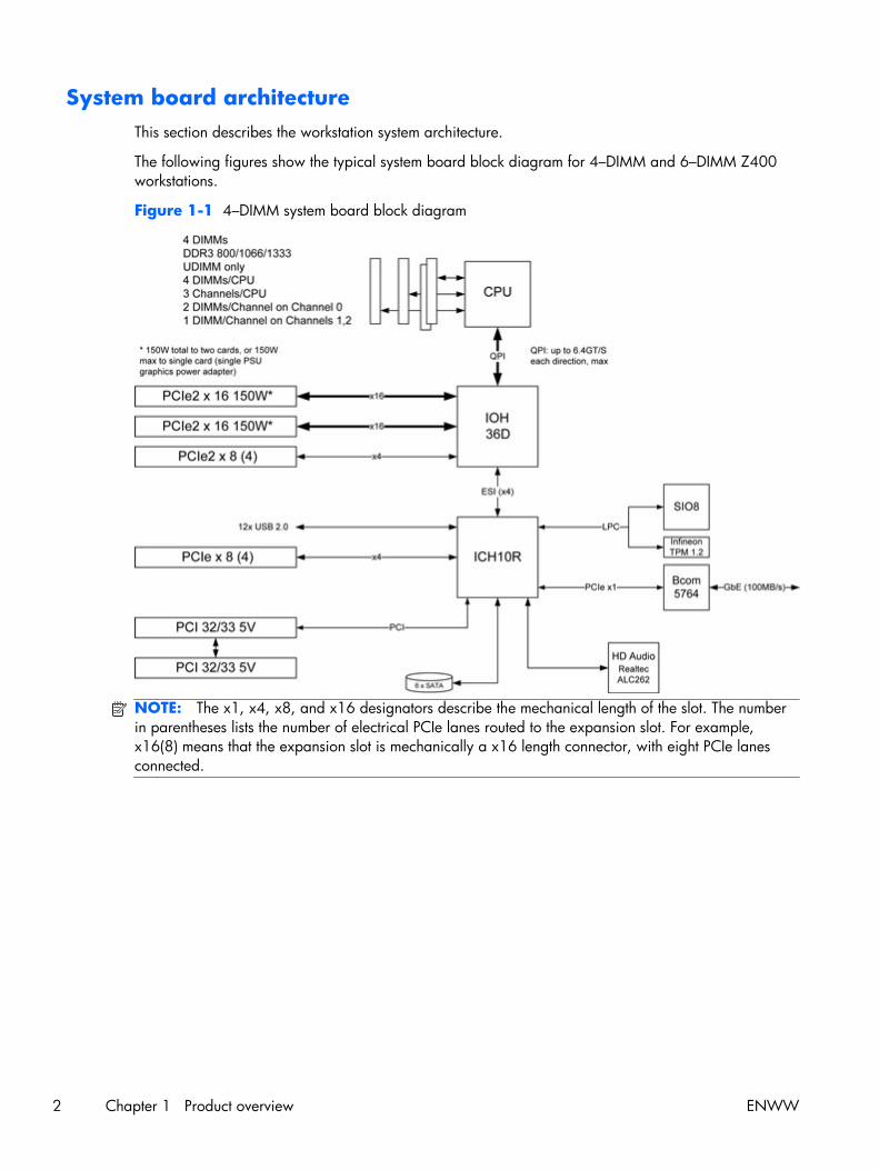
System board architectureThis section describes the workstation system architecture.
The following figures show the typical system board block diagram for 4–DIMM and 6–DIMM Z400workstations.
Figure 1-1 4–DIMM system board block diagram
NOTE: The x1, x4, x8, and x16 designators describe the mechanical length of the slot. The numberin parentheses lists the number of electrical PCIe lanes routed to the expansion slot. For example,x16(8) means that the expansion slot is mechanically a x16 length connector, with eight PCIe lanesconnected.
2 Chapter 1 Product overview ENWW
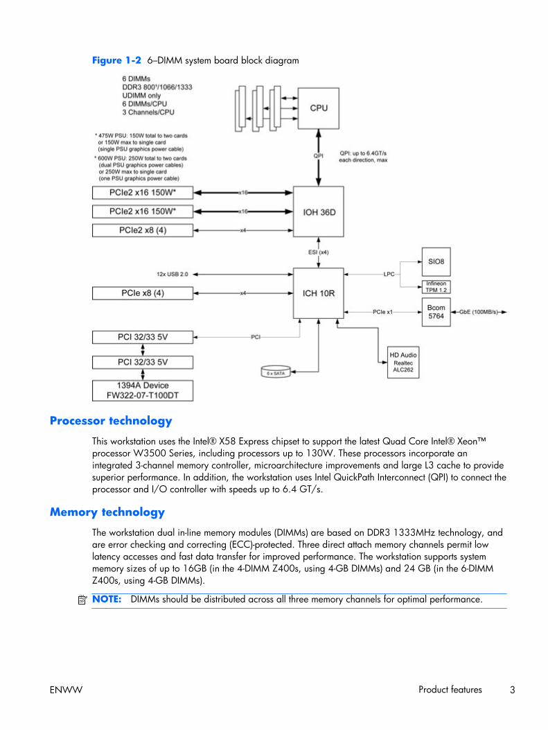
Figure 1-2 6–DIMM system board block diagram
Processor technology
This workstation uses the Intel® X58 Express chipset to support the latest Quad Core Intel® Xeon™processor W3500 Series, including processors up to 130W. These processors incorporate anintegrated 3-channel memory controller, microarchitecture improvements and large L3 cache to providesuperior performance. In addition, the workstation uses Intel QuickPath Interconnect (QPI) to connect theprocessor and I/O controller with speeds up to 6.4 GT/s.
Memory technology
The workstation dual in-line memory modules (DIMMs) are based on DDR3 1333MHz technology, andare error checking and correcting (ECC)-protected. Three direct attach memory channels permit lowlatency accesses and fast data transfer for improved performance. The workstation supports systemmemory sizes of up to 16GB (in the 4-DIMM Z400s, using 4-GB DIMMs) and 24 GB (in the 6-DIMMZ400s, using 4-GB DIMMs).
NOTE: DIMMs should be distributed across all three memory channels for optimal performance.
ENWW Product features 3

Graphics
The workstation supports PCIe Gen2 (PCIe2) bus speeds and can support dual PCIe Gen2 graphicscards in PCIe2 x16 slots.
When using the 475W power supply, the workstation supports:
● A graphics card up to 150W in the primary graphics slot
● A second graphics card in the second PCIe2 x16 slot (slot 4), provided the combined powerconsumption of both cards does not exceed 150W
When using the optional 600W power supply, the workstation supports:
● A graphics card up to 250W in the primary graphics slot
● A second graphics card in the second PCIe2 x16 slot (slot 4), provided the combined powerconsumption of both cards does not exceed 250W
Expansion card slots
The workstation implements one Intel X58 I/O chip to provide a total of six high-performance graphicsand I/O slots. In addition to the two full x16 PCIe Gen2 slots, two additional PCIe x8 (4) slots (x8mechanically, x4 electrically) provide extra I/O bandwidth for high speed I/O cards. Open endedPCIe x8 connectors let the user install x16 physical size cards in the x8 (4) slots.
Additional features
Redundant array of independent disks (RAID) configurations for SATA support modes 0, 1, 5 and 10.eSATA (3.0 Gbps) is supported using an optional adapter. The workstation provides 8 external and 4internal USB 2.0 ports. The 475W power supply is 85% efficient and enables Energy Star Version 5.0system configurations. HP WattSaver technology enables support of the European Union ERP Lot 6power limit of 1W in off mode. HP Quiet Fan Technology enables quiet system operation. A plug-incard supports Serial Attached SCSI (SAS) drives.
4 Chapter 1 Product overview ENWW

Workstation componentsThis section describes workstation components, including front and rear panel components.
For complete and current information on supported accessories and components for the workstation,see http://partsurfer.hp.com.
Chassis components
The following image shows the components of a typical workstation configuration. Drive configurationscan vary.
Figure 1-3 Workstation components
Table 1-1 Workstation component descriptions
Item Description Item Description
1 Power supply 9 Memory module (DIMM)
2 Side access panel 10 System board
3 Rear system fan 11 PCIe card
4 SFF Hard drive 12 PCI card
5 Hard disk drive 13 Airflow guide (for 6-DIMM Z400 product)
6 Optical drive 14 Speaker
7 Processor (CPU) heatsink 15 Front bezel
8 Processor 16 Chassis
ENWW Product features 5
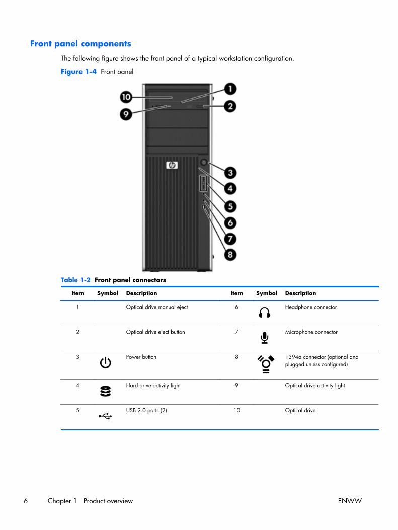
Front panel components
The following figure shows the front panel of a typical workstation configuration.
Figure 1-4 Front panel
Table 1-2 Front panel connectors
Item Symbol Description Item Symbol Description
1 Optical drive manual eject 6 Headphone connector
2 Optical drive eject button 7 Microphone connector
3 Power button 8 1394a connector (optional andplugged unless configured)
4 Hard drive activity light 9 Optical drive activity light
5 USB 2.0 ports (2) 10 Optical drive
6 Chapter 1 Product overview ENWW
Rear panel components
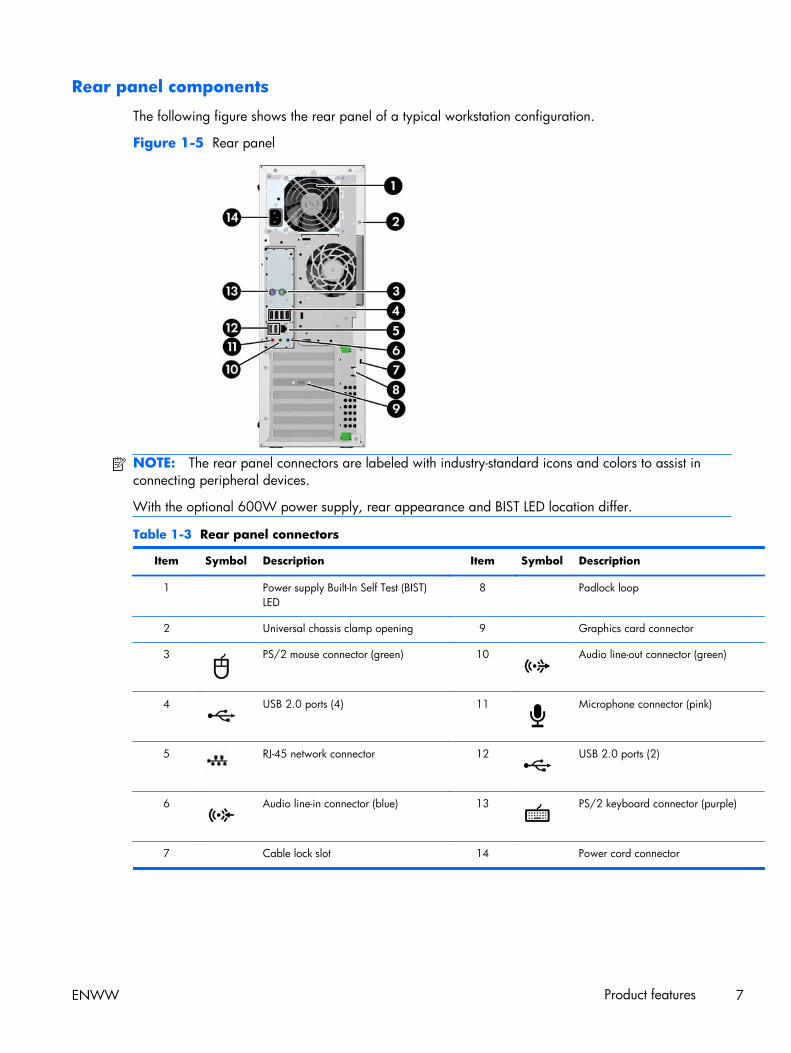
The following figure shows the rear panel of a typical workstation configuration.
Figure 1-5 Rear panel
NOTE: The rear panel connectors are labeled with industry-standard icons and colors to assist inconnecting peripheral devices.
With the optional 600W power supply, rear appearance and BIST LED location differ.
Table 1-3 Rear panel connectors
Item Symbol Description Item Symbol Description
1 Power supply Built-In Self Test (BIST)LED
8 Padlock loop
2 Universal chassis clamp opening 9 Graphics card connector
3 PS/2 mouse connector (green) 10 Audio line-out connector (green)
4 USB 2.0 ports (4) 11 Microphone connector (pink)
5 RJ-45 network connector 12 USB 2.0 ports (2)
6 Audio line-in connector (blue) 13 PS/2 keyboard connector (purple)
7 Cable lock slot 14 Power cord connector
ENWW Product features 7
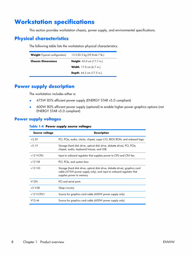
Workstation specificationsThis section provides workstation chassis, power supply, and environmental specifications.
Physical characteristicsThe following table lists the workstation physical characteristics.
Weight (Typical configuration) 13.5-20.3 kg (29.8-44.7 lb.)
Chassis Dimensions Height: 45.0 cm (17.7 in.)
Width: 17.0 cm (6.7 in.)
Depth: 44.5 cm (17.5 in.)
Power supply descriptionThe workstation includes either a:
● 475W 85% efficient power supply (ENERGY STAR v5.0 compliant)
● 600W 80% efficient power supply (optional) to enable higher power graphics options (notENERGY STAR v5.0 compliant)
Power supply voltages
Table 1-4 Power supply source voltages
Source voltage Description
+3.3V PCI, PCIe, audio, clocks, chipset, super I/O, BIOS ROM, and onboard logic
+5.1V Storage (hard disk drive, optical disk drive, diskette drive), PCI, PCIe,chipset, audio, keyboard/mouse, and USB
+12 V-CPU Input to onboard regulator that supplies power to CPU and CPU fan
+12 V-B PCI, PCIe, and system fans
+12 V-D Storage (hard disk drive, optical disk drive, diskette drive), graphics cardcable (475W power supply only), and input to onboard regulator thatsupplies power to memory
V12N PCI and serial ports
+5 V-SB Sleep circuitry
+12 V-CPU1 Source for graphics card cable (600W power supply only)
V12–M Source for graphics card cable (600W power supply only)
8 Chapter 1 Product overview ENWW
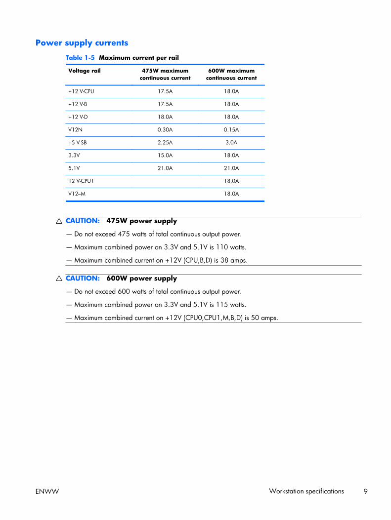
Power supply currents
Table 1-5 Maximum current per rail
Voltage rail 475W maximumcontinuous current
600W maximumcontinuous current
+12 V-CPU 17.5A 18.0A
+12 V-B 17.5A 18.0A
+12 V-D 18.0A 18.0A
V12N 0.30A 0.15A
+5 V-SB 2.25A 3.0A
3.3V 15.0A 18.0A
5.1V 21.0A 21.0A
12 V-CPU1 18.0A
V12–M 18.0A
CAUTION: 475W power supply
— Do not exceed 475 watts of total continuous output power.
— Maximum combined power on 3.3V and 5.1V is 110 watts.
— Maximum combined current on +12V (CPU,B,D) is 38 amps.
CAUTION: 600W power supply
— Do not exceed 600 watts of total continuous output power.
— Maximum combined power on 3.3V and 5.1V is 115 watts.
— Maximum combined current on +12V (CPU0,CPU1,M,B,D) is 50 amps.
ENWW Workstation specifications 9

Power supply specifications
Table 1-6 Power supply specifications
Item Description
Power supply ● 475W Wide Ranging, Active PFC and 85%efficient or
● 600W Wide Ranging, Active PFC and 80%efficient (optional)
Operating voltage range 90 – 269 VAC
Rated voltage range 100–240 VAC 118 VAC
Rated line frequency 50–60 Hz 400 Hz
Operating line frequency range 47–66 Hz 393–407 Hz
Rated input current 10A @ 100-127 VAC
6A @ 200–240 VAC
10A @ 118 VAC
Heat dissipation
(Configuration and software dependent)
475W power supply:
● Typical: 954 Btu/hr = (240.3 kg-cal/hr)
● Max: 1977 Btu/hr = (498.2 kg-cal/hr)
600W power supply:
● Typical: 1536 Btu/hr = (387 kg-cal/hr)
● Max: 2560 Btu/hr = (645 kg-cal/hr)
Power supply fan One fan, 92mm x 25mm, variable speed
FEMP Standby Power compliant @115V (<2W in S5 –Power Off)
Yes
ERP Lot 6 Compliant @230V (<1w in S5 – Power Off) Yes
Built-in Self Test LED Yes
Surge tolerant full ranging power supply (withstandspower surges up to 2000V)
Yes
Power Consumption in sleep mode (as defined byENERGY STAR) - Suspend to RAM (S3) (InstantlyAvailable PC)
<6 watts
10 Chapter 1 Product overview ENWW
Power consumption and heat dissipation
Power consumption and heat dissipation specifications are available for multiple configurations. Toreview available specifications, see http://www.hp.com/go/quickspecs.
To reach zero power consumption, unplug the workstation from the power outlet or use a power stripwith an on/off switch. For additional information about power-saving features, see the operating systeminstallation instructions.
This product is in compliance with U.S. Executive Order 13221.
System fans
This workstation includes:
● One rear system fan
● One CPU heatsink fan
● One power supply fan
Additional fans may include:
● Optional front system fan for special environments.
● CPU voltage regulator fan for Z400s equipped with liquid cooling solution.
● Onboard fans on some graphics cards.
Resetting the power supply
If an overload triggers the power supply overload protection, power is immediately disconnected.
To reset the power supply:
1. Disconnect the power cord from the workstation.
2. Determine what caused the overload and fix the problem. For troubleshooting information, seeDiagnostics and troubleshooting on page 164.
3. Reconnect the power cord and restart the workstation.
When you power off the workstation through the operating system, power consumption falls belowwhat is considered low power consumption but does not reach zero. This low power consumptionfeature extends the life of the power supply.
ENWW Workstation specifications 11

Environmental specificationsThe following table lists the environmental specifications of HP Workstations.
Table 1-7 HP Workstation environmental specifications
Temperature
Operating: 5 to 35°C (40 to 95°F)
Non-operating: -40 to 60°C (-40 to 140°F)
NOTE: Derate by one degree C (1.8 degrees F) for every 305m (1,000 ft.) altitude over1,524m (5,000 ft.).
HumidityOperating: 8 to 85% Relative Humidity (RH), non-condensing
Non-operating: 8 to 90% Relative Humidity, non-condensing
AltitudeOperating: 0 to 3,048m (10,000 ft.)
Non-operating: 0 to 9,144m (30,000 ft.)
Shock
Operating: ½-sine: 40g, 2-3ms
Non-operating:
● ½-sine: 160 cm/s, 2-3ms (~100g)
● square: 422 cm/s, 20g
NOTE: Values represent individual shock events and do not indicate repetitive shock events.
Vibration
Operating Random: 0.5g (rms), 5-300 Hz
Non-Operating: random: 2.0g (rms), 10-500 Hz
NOTE: Values do not indicate continuous vibration.
ENERGY STAR QualificationHP computers marked with the ENERGY STAR logo are compliant with the applicable U.S.Environmental Protection Agency (EPA) ENERGY STAR specifications for computers. The EPA ENERGYSTAR logo does not imply endorsement by the EPA. As an ENERGY STAR Partner, Hewlett-PackardCompany has determined the products marked with the ENERGY STAR logo are ENERGY STARqualified per the applicable ENERGY STAR guidelines for energy efficiency. The following logoappears on all ENERGY STAR qualified computers.
The ENERGY STAR Computers Program was created by the EPA to promote energy efficiency andreduce air pollution through more energy-efficient equipment in homes, offices, and factories. One wayproducts achieve this energy efficiency is by reducing power consumption when not being used throughthe Microsoft Windows Power Management feature.
12 Chapter 1 Product overview ENWW

The Power Management feature enables the workstation to enter a low-power (or “sleep”) mode after aperiod of inactivity. When used with an external monitor that is ENERGY STAR qualified, this featurealso supports the similar power management features of the external monitor.
To take advantage of this energy savings:
● The Power Management feature has been preset to suspend the workstation to a sleep state after30 minutes of inactivity.
● The Power Management feature has been preset to suspend the monitor to a sleep state after 15minutes of inactivity.
Both the computer and monitor can be woken from sleep mode through user interaction with any of thecomputer input devices (mouse, keyboard, and so on). when configured with Wake On LAN (WOL)enabled, the workstation can also be woken by a network signal.
See the EPA ENERGY STAR Power Management Web site for more information about the energy andfinancial savings potential of the Power Management Feature: http://www.energystar.gov/powermanagement.
See the EPA ENERGY STAR Web site for more information about the ENERGY STAR program and itsenvironmental benefits: http://www.energystar.gov.
CAUTION: Using the Energy Save Monitor feature with monitors that are not ENERGY STARqualified can cause video distortion when an Energy Save timeout occurs.
NOTE: ENERGY STAR is not supported on Linux workstations.
If it is necessary to restore the operating system, you must also reset the ENERGY STAR settings (ifapplicable) after the restore.
To verify the factory default power settings for your workstation, select Start>Control Panel, andthen double-click Power Options.
NOTE: ENERGY STAR is not supported with the optional 600W power supply.
ENWW Workstation specifications 13

ERP compliance modeThis computer provides a European Union ERP Lot 6 (Energy-Related Products Directive) compliancemode.
When enabled, this feature lets the workstation shut down to the lowest possible power state byremoving all power to the system board.
When disabled, the workstation powers down conventionally.
When the workstation is shut down in ERP compliance mode, you must use the workstation powerbutton to restore power.
Enabling ERP compliance mode
To enable ERP Lot 6 compliance mode:
1. Press F10 during start up.
2. Using the arrow keys, select the Power>Hardware Power Management>ERPCompliance Mode, and then select Enable.
3. Press F10 to accept the change.
4. Select File>Save Change and Exit, and then press F10 to accept the change.
Disabling ERP compliance mode
To disable the ERP compliance mode:
1. Press F10 during start up.
2. Select Power>Hardware Power Management>ERP Compliance Mode, and then selectDisable.
3. Press F10 to accept the change.
4. Select File>Save Change and Exit, and then press F10 to accept the change.
AccessibilityHP is committed to developing products, services, and information that is easier to access for allcustomers, including customers with disabilities and age-related limitations. HP products with WindowsVista® Business and Microsoft® Windows® XP Professional preinstalled are designed for accessibility,and these products are tested with industry-leading Assistive Technology products. For more informationsee http://www.hp.com/accessibility.
14 Chapter 1 Product overview ENWW

Hyper-threadingThis HP workstation supports Hyper-threading.
Hyper-Threading Technology (HTT), is an Intel-proprietary technology used to provide processparallelization. The operating system treats a processor with Hyper-Threading enabled as twoprocessors instead of one. This improves performance under certain workloads by getting useful workfrom parts of the processor that would otherwise remain idle. Hyper-threading relies on support fromthe operating system as well as the CPU.
To implement hyper-threading, see The Computer Setup (F10) Utility on page 31.
SATA Power ManagementSATA Power Management enables or disables SATA bus and/or device power management.
Intel Turbo Boost TechnologyThe HP Z Workstation series supports Intel® Turbo Boost Technology.
When the workload does not require all CPU cores, this feature diverts power from inactive cores toactive cores, increasing their performance. This lets the CPU run at a higher than normal rate.
Use the workstation BIOS to enable, enhance, or disable Turbo Boost. For instructions on setting BIOSfeatures, see The Computer Setup (F10) Utility on page 31.
HP Cool ToolsAn HP workstation with Windows 7 or Windows Vista includes additional software not installed whenyou first start the workstation. To access or learn more about these additional preinstalled tools on theworkstation that can enhance the workstation experience:
1. Open the HP Cool Tools folder by selecting Start>All Programs>HP Cool Tools.
2. Select the HP Cool Tools icon on the desktop.
3. To learn more about these applications, select HP Cool Tools—Learn More.
4. To install or launch the applications, select the appropriate application.
NOTE: A preinstalled Windows Vista Business operating system does not contain a Cool Tools icon,shortcut or folder, but several of the tool programs are included, such as Performance TuningFramework.
ENWW Workstation specifications 15
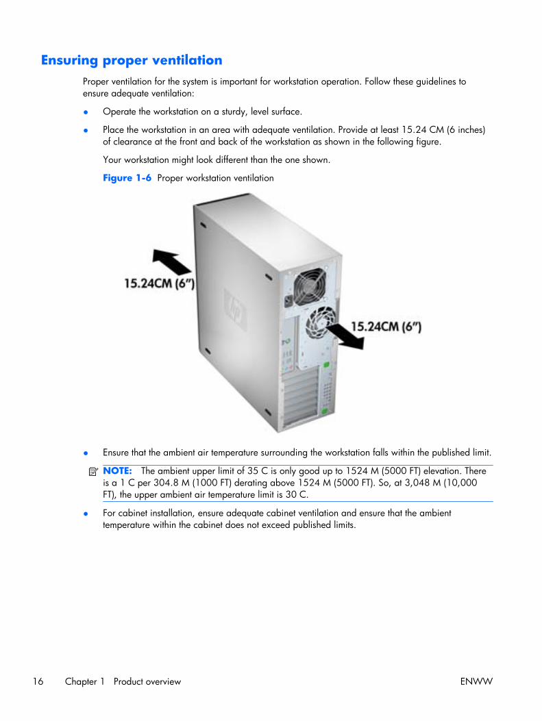
Ensuring proper ventilationProper ventilation for the system is important for workstation operation. Follow these guidelines toensure adequate ventilation:
● Operate the workstation on a sturdy, level surface.
● Place the workstation in an area with adequate ventilation. Provide at least 15.24 CM (6 inches)of clearance at the front and back of the workstation as shown in the following figure.
Your workstation might look different than the one shown.
Figure 1-6 Proper workstation ventilation
● Ensure that the ambient air temperature surrounding the workstation falls within the published limit.
NOTE: The ambient upper limit of 35 C is only good up to 1524 M (5000 FT) elevation. Thereis a 1 C per 304.8 M (1000 FT) derating above 1524 M (5000 FT). So, at 3,048 M (10,000FT), the upper ambient air temperature limit is 30 C.
● For cabinet installation, ensure adequate cabinet ventilation and ensure that the ambienttemperature within the cabinet does not exceed published limits.
16 Chapter 1 Product overview ENWW

● Never restrict the incoming or outgoing airflow of the workstation by blocking any vents or airintakes as shown in the following figure.
Figure 1-7 Proper workstation placement
ENWW Workstation specifications 17

2 Setting up the operating system
This chapter provides setup and update information for the workstation operating system. It includesthese topics:
Topics
Setting up the Microsoft operating system on page 19
Setting up Red Hat Enterprise Linux on page 20
Setting up Novell SLED on page 21
Updating the workstation on page 21
This chapter also includes information on how to determine that you have the latest BIOS, drivers, andsoftware updates installed on the workstation.
CAUTION: Do not add optional hardware or third-party devices to the HP workstation until theoperating system is successfully installed. Adding hardware might cause errors and prevent theoperating system from installing correctly.
18 Chapter 2 Setting up the operating system ENWW
Setting up the Microsoft operating systemNOTE: If you ordered a downgrade from Windows 7 or Windows Vista to Windows XP Professionaloperating system, your system will be preinstalled with Windows XP Professional operating system.With this configuration, you will receive recovery media for the Windows 7 or Windows Vistaoperating system only. In case you need to restore or recover the Windows XP Professional operatingsystem in the future, it is important that you create recovery media disks for Windows XP Professionaloperating system after first boot.
When you first apply power to the workstation, the operating system is installed. This process takesapproximately 5 to 10 minutes. Carefully follow the instructions on the screen to complete theinstallation.
CAUTION: After installation has started, do not turn off the workstation until the process is complete.Turning off the workstation during installation can damage the installation and operation of thesoftware.
For complete operating system installation and configuration instructions, see the operating systemdocumentation that was provided with the workstation. Additional information is available in the onlinehelp tool after you successfully install the operating system.
Installing or upgrading device driversTo install hardware devices after the operating system is installed, you must install the appropriatedevice drivers before you install the devices. Follow the installation instructions that came with thedevice. In addition, for optimum performance, your operating system must have the most recentupdates, patches, and software fixes. For additional driver and software update information, refer toUpgrading device drivers on page 23.
Transferring files and settings to your Windows workstationThe Microsoft Windows operating system offers data migration tools that helps you choose and transferfiles and data from a Windows computer to your Windows 7, Windows Vista, or Windows XPProfessional operating system workstation.
For instructions on how to use these tools, see the documents at http://www.microsoft.com.
ENWW Setting up the Microsoft operating system 19

Setting up Red Hat Enterprise LinuxHP offers an HP Installer Kit for Linux (HPIKL) to supplement Red Hat box sets and help HP Linuxcustomers customize their system image. The HPIKL contains the HP driver CD and device drivers tosuccessfully setup up the Red Hat Enterprise Linux (RHEL) operating system, The HP Installer Kit for LinuxCDs are currently available for download at http://www.hp.com/support/workstation_swdrivers.
Installing with the HP driver CDTo install the HP driver CD, see “Installing with the HP Installer Kit for Linux” in the HP Workstations forLinux manual at http://www.hp.com/support/workstation_manuals.
20 Chapter 2 Setting up the operating system ENWW
Installing and customizing Red Hat-enabled workstationsLinux-enabled workstations require the HP Installer Kit and the purchase of a Red Hat Enterprise Linuxbox set. The Installer kit includes the HP CDs necessary to complete the installation of all versions of theRed Hat Enterprise Linux box set that have been qualified to work on an HP workstation.
To use the drivers in the HP Installer kit for Linux other than RHEL, you must manually extract the driversfrom the HP Driver CD and install them. HP does not test the installation of these drivers on other Linuxdistributions nor does HP support this operation.
Verifying hardware compatibility
To see which Linux versions have been qualified to work on HP Workstations visit http://www.hp.com/support/linux_hardware_matrix.
Setting up Novell SLEDTo set up the SUSE Linux Enterprise Desktop (SLED) on systems preloaded with the operating system:
1. Boot the workstation.
2. Start the Installation Settings and enter the password, network, graphics, time, keyboard settings,and Novell Customer Center Configuration for the workstation.
NOTE: During Installation Settings after the first time after booting the system the Novellsubscription can be activated from the Novell Customer Center Configuration screen. Visit the fullNovell Customer Center documentation at http://www.novell.com/documentation/ncc/.
Updating the workstationHP is constantly working on improving your total workstation experience. To ensure that the workstationleverages the latest enhancements, HP recommends that you install the latest BIOS, driver, and softwareupdates on a regular basis.
Updating the workstation after first bootAfter successfully booting the workstation for the first time, you should follow these guidelines to ensurethat the workstation is up-to-date:
● Ensure that you have the latest system BIOS loaded. See Upgrading the BIOS on page 21 forinstructions.
● Ensure that you have the latest drivers for your system. See Upgrading device driverson page 23 for instructions.
● Become familiar with your available HP resources.
● Consider a subscription to Driver Alerts at http://www.hp.com/go/subscriberschoice.
Upgrading the BIOSFor optimum performance, determine the BIOS revision on the workstation, and upgrade it if necessary.
ENWW Setting up Novell SLED 21

Determining current BIOS
To determine the current BIOS of the workstation during system power up:
1. Wait for F10=setup to appear on the lower right corner of the screen.
2. Press F10 to enter the F10 Setup utility.
The F10 Setup utility displays the workstation BIOS version under File > System Information.
3. Note the workstation BIOS version so that you can compare it with the BIOS versions that appearon the HP website.
22 Chapter 2 Setting up the operating system ENWW

Upgrading BIOS
To find and download the latest available BIOS, which includes the latest enhancements:
1. Go to http://www.hp.com/go/workstationsupport.
2. Select Download Drivers and Software from the left menu column under Tasks.
3. Follow the instructions to locate the latest BIOS available for the workstation.
4. If the BIOS on the Web site is the same as the version on your system, no further action isrequired.
5. If the BIOS on the Web site is a version later than the one on your system, download theappropriate version for the workstation. Follow the instructions in the release notes to complete theinstallation.
Upgrading device driversIf you install a peripheral device (such as a printer, display adapter, or network adapter), confirm youhave the latest device drivers loaded. If you purchased your device through HP, visit the HP Web site todownload the latest drivers for your device. These drivers have been tested to ensure the bestcompatibility between your device and your HP workstation.
If you did not purchase your device from HP, HP recommends visiting the HP Web site first to see ifyour device and its drivers have been tested for HP workstation compatibility. If no driver is available,visit the device manufacturer's Web site to download the latest drivers.
To upgrade device drivers:
1. Go to http://www.hp.com/go/workstationsupport.
2. Select Download Drivers and Software from the left menu column under Tasks.
3. Follow the instructions to find the latest drivers available for the workstation.
If a needed driver is not found, see the Web site of the manufacturer of the peripheral device.
ENWW Updating the workstation 23
3 Restoring the operating system
This chapter describes how to restore the Windows or Linux operating system. It includes these topics:
Topics
Restore methods on page 24
Ordering backup software on page 25
Restoring Windows 7 or Windows Vista on page 25
Restoring Windows XP Professional on page 26
Restoring Novell SLED on page 28
Restore methodsThe Windows 7 or Windows Business Vista operating system can be reinstalled using the HPRestorePlus! process. The Windows XP Professional operating system can be reinstalled using theRestorePlus! process or the HP Backup and Recovery Manager.
● RestorePlus!
The RestorePlus! process reinstalls the Windows operating system and device drivers (for devicesincluded with the system) to a near-factory state. The process does not back up or recover data onthe hard drive. Some application software might not be restored using this process and must beinstalled from the appropriate application CD.
● HP Backup and Recovery Manager (HPBR) Recovery Point
The HP Backup and Recovery Manager application can be used to capture and restore thecontents of the system partition. It captures a snapshot of the system partition and stores it in aRecovery Point. Everything on the system partition at the time the recovery point was made issaved.
NOTE: HP Backup and Restore is only supported on the HP xw6600 and xw8600Workstations.
The Recovery Point is saved to the hard drive and can be burned to media for safekeeping.
CAUTION: These methods restore the operating system, but not data. Data must be backed upregularly to avoid loss.
24 Chapter 3 Restoring the operating system ENWW
Ordering backup softwareIf you cannot create system recovery CDs or DVDs, you can order a recovery disk set from the HPsupport center. To obtain the support center telephone number for your region seehttp://www.hp.com/support/contactHP.
Restoring Windows 7 or Windows VistaThis section describes how to restore Windows 7 or Windows Vista.
Ordering the RestorePlus! mediaIf you ordered restore media with your workstation, the media is included with your workstationcomponents.
If you did not order restore media, call HP Support and request a RestorePlus! media kit. For worldwidetechnical support phone numbers, see http://www.hp.com/support.
Restoring the operating systemNOTE: Windows 7 and Windows Vista provide a backup and restore application as well. To learnmore about this application, see the Microsoft Web site.
CAUTION: Before you restore the operating system, back up your data.
When you run RestorePlus! from media, the process deletes all information on the primary hard drive,including all partitions.
To restore Windows 7 or Windows Vista:
1. Boot from the RestorePlus! DVD to start the RestorePlus! process. You must start from theRestorePlus! DVD to install device drivers and settings.
2. Follow the prompts to restore your operating system.
Some application software might not be restored using this process. If software is not restored, install itfrom the appropriate application DVD.
ENWW Ordering backup software 25
Restoring Windows XP ProfessionalThis section describes how to restore the Windows XP Professional operating system.
NOTE: The workstation must have a CD or DVD writer installed to create the media set.
Creating RestorePlus! mediaThe RestorePlus! kit can be created using the files contained on the hard drive. To create the restoremedia:
1. Boot the workstation.
2. During boot up, an HP Backup and Recovery Manager screen is displayed prompting you tocreate Recovery CDs or DVDs. Select Now.
3. An Initial Recovery Point (IRP) of the system is captured. This is a snapshot of the system harddrive. The capture can take more than 10 minutes.
4. After the IRP is created, you can create a set of backup CDs or DVDs.
To create a RestorePlus! media set including the Windows XP operating system CD, selectRestorePlus! > Microsoft Windows XP operating system > Supplemental media.
NOTE: Depending on the options, there might be additional DVDs you can create.
5. Follow the prompts to create RestorePlus!, operating system, and HPBR media.
If you are unable to create CD/DVDs on your workstation, call HP Support and request a RestorePlus!media kit. For worldwide technical support phone numbers, see http://www.hp.com/support.
26 Chapter 3 Restoring the operating system ENWW

Creating HP Backup and Recovery (HPBR) mediaNOTE: HPBR is only supported on Windows XP systems. For details, refer to the documentation onthe Supplemental Software - HP Backup and Recovery CD included with the workstation. Thedocumentation can be accessed during installation.
The Initial Recovery Point can be burned to optical media and used to recover a system. This sectiondescribes making the media.
NOTE: The workstation must have a CD or DVD writer to create the media set.
To create HPBR recovery media:
1. The Initial Recovery Point was captured when the RestorePlus! media set was created previously.
If the IRP was not created, start the HP Backup and Recovery Manager and create recovery pointsusing the Expert mode. Follow the HPBR online documentation for instructions.
2. Burn the IRP to media from HPBR.
Select HPBR Start > All Programs > HP Backup & Recovery > HP Backup andRecovery Manager.
3. Select Next at the first screen.
Select Create recovery CDs or DVDs to recover the system, and then select Next.
4. Choose Next to display a list of available CD image and the recovery points.
5. Check the box next to Initial Recovery Point, and then select Next.
6. Follow the instructions to create the media.
ENWW Restoring Windows XP Professional 27
Restoring the operating systemCAUTION: Before you restore the operating system, back up your data.
When you run RestorePlus! from media, the process deletes all information on the primary hard drive,including all partitions. If you run RestorePlus! from the recovery partition, only the root (C:) partition isaffected.
Using RestorePlus!
To restore with RestorePlus!:
1. Boot the workstation from the RestorePlus! DVD. You must start from the RestorePlus! DVD fordevice drivers and settings to be installed.
2. Follow the prompts to restore the operating system.
Some application software might not be restored using this process. If software is not restored, install itfrom the appropriate application DVD.
Using HPBR
To restore with the HPBR Initial Recovery Point media:
1. Boot the workstation from the Initial Recovery Point media.
2. Follow the prompts to restore the system to the state when the IRP was created.
Using the recovery partition
A system that shipped with Windows XP includes a recovery partition. You can boot the system fromthat recovery partition.
From the recovery partition you can perform a system restore using the HPBR Initial Recovery Point, if itwas created. If it was not, you can use a RestorePlus! install.
To restore using the recovery partition:
1. Boot the workstation.
2. When prompted on the boot screen to enter the Recovery Manager, press F11.
TIP: The opportunity to press F11 during the boot process is small. It comes about the time theF10 prompt appears.
NOTE: To ensure that the recovery processes reinstall on the correct hard drive, do notdisconnect the target drive during the recovery process.
3. Follow the prompts to restore the system to factory-like condition.
Restoring Novell SLEDThe SLED restore media is required to restore the Linux operating system.
28 Chapter 3 Restoring the operating system ENWW

Creating restore mediaTHE SUSE Linux Enterprise Desktop preload includes a SUSE ISO icon on the desktop. You can clickthis icon to go to the /iso directory. The /iso directory contains all iso images used to preload yourworkstation. To recover or restore the original image, follow the instructions in the readme file in the /iso directory to copy the ISO image file onto CDs.
NOTE: Make copies of the ISO recovery images on CD as backup files in case your workstationexperiences a hard drive failure.
ENWW Restoring Novell SLED 29
4 System management
This section describes the tools and utilities that provide system management for the workstation. Itincludes these topics:
Topics
BIOS ROM on page 31
The Computer Setup (F10) Utility on page 31
Workstation management on page 43
30 Chapter 4 System management ENWW

BIOS ROMThe BIOS ROM is a collection of machine language applications stored as firmware in ROM. It includesfunctions such as POST, PCI device initialization, Plug and Play support, power management, and theComputer Setup (F10) Utility. The BIOS ROM is a 1-MB Serial Peripheral Interface (SPI) port.
See http://www.hp.com/go/quickspecs to review the latest BIOS ROM specifications.
The Computer Setup (F10) UtilityThis section contains these topics:
Topics
Computer Setup (F10) functionality on page 31
Accessing the Computer Setup (F10) Utility on page 33
The Computer Setup (F10) Utility menu on page 34
Computer Setup (F10) functionalityThe Computer Setup (F10) Utility lets you:
● Change factory default settings and set or change the workstation configuration, which might benecessary when you add or remove hardware.
● Determine if all devices installed on the workstation are recognized by the system and functioning.
● Determine information about the operating environment of the workstation.
● Solve system configuration errors that are detected but not fixed during the Power-On Self-Test(POST).
● Establish and manage passwords and other security features.
● Establish and manage energy-saving time-outs (not supported on Linux platforms).
● Modify or restore factory default settings.
● Set the workstation date and time.
● Set, view, change, or verify the workstation configuration, including settings for CPU, graphics,memory, audio, storage, communications, and input devices.
● Modify the boot order of installed mass storage devices such as SATA, SAS, diskette drives,optical disk drives, network drives, LS-120 drives and USB boot devices.
● Configure the boot priority of SATA and SAS hard-drive controllers.
● Enable or disable Network Server Mode, which lets the workstation start the operating systemwhen the power-on password is enabled with or without a keyboard or mouse attached. Whenattached to the workstation, the keyboard and mouse remain locked until the power-on passwordis entered.
● Enable or disable POST Messages to change the display status of POST messages. POSTMessages disabled suppresses most POST messages, such as memory count, product name, and
ENWW BIOS ROM 31

other nonerror text messages. If a POST error occurs, the error is displayed regardless of the modeselected. To manually switch to POST Messages Enabled during POST, press any key except F1through F12.
● Specify an Ownership Tag, which appears when the workstation is powered on or restarted.
● Specify the Asset Tag or property identification number assigned by the company to thisworkstation.
● Enable power-on password prompts during system restarts (warm-starts) and power on.
● Hide or show the integrated I/O functionality, including serial, USB, or parallel ports, audio, orembedded NIC. Hidden devices are inaccessible, which increases system security.
● Enable or disable removable media boot ability.
● Enable or disable removable media write ability (if supported by hardware).
● Replicate the workstation setup by saving system configuration information on CD or diskette andrestoring it on workstations.
● Execute self-tests on specified SATA and SAS hard disk drives (if supported by the drive).
32 Chapter 4 System management ENWW

Accessing the Computer Setup (F10) UtilityTo access the Computer Setup (F10) Utility menu:
1. Power on or restart the workstation.
2. When the display is active and F10=Setup appears in the lower right corner of the screen, pressF10.
If you do not press F10 at the appropriate time, try again. Turn the workstation off, then on, andpress F10 again to access the utility. You can also press the Ctrl + Alt + Delete keys beforestarting if you miss the opportunity to press F10.
3. Select the language from the list and press the Enter key.
In the Computer Setup (F10) Utility menu, five headings are displayed: File, Storage, Security,Power, and Advanced.
4. Use the left and right arrow keys to select the appropriate heading, use the up and down arrowkeys to select an option, and then press Enter.
5. Choose from the following:
● To apply and save changes, select File>Save Changes, and then select F10=YES.
● To remove changes you have made, select Ignore Changes and then select F10=YES.
● To reset to factory settings, select File>Default Setup>Restore Factory Settings asDefault. Press F10 to accept the changes, and then select Apply Defaults and Exit. Thisrestores the original factory system defaults.
CAUTION: Do not power off the workstation while the ROM is saving the Computer Setup (F10)Utility changes, because the Complementary Metal-Oxide Semiconductor (CMOS) could becomecorrupted. After you exit the F10 Setup screen, you can disconnect power from the workstation.
ENWW The Computer Setup (F10) Utility 33
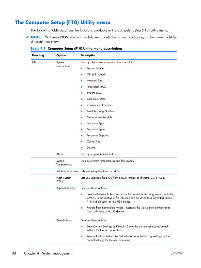
The Computer Setup (F10) Utility menuThe following table describes the functions available in the Computer Setup (F10) utility menu.
NOTE: With new BIOS releases, the following content is subject to change, so the menu might bedifferent than shown.
Table 4-1 Computer Setup (F10) Utility menu descriptions
Heading Option Description
File SystemInformation
Displays the following system characteristics:
● Product Name
● QPI Link Speed
● Memory Size
● Integrated MAC
● System BIOS
● Boot Block Date
● Chassis serial number
● Asset Tracking Number
● Management Module
● Processor Type
● Processor Speed
● Processor Stepping
● Cache Size
● DIMMs
About Displays copyright information.
SystemTemperatures
Displays system temperatures and fan speeds.
Set Time and Date Lets you set system time and date.
Flash SystemROM
Lets you upgrade the BIOS from a ROM image on diskette, CD, or USB.
Replicated Setup Provides these options:
● Save to Removable Media—Saves the workstation configuration, includingCMOS, in the qsetup.txt file. This file can be saved to a formatted, blank1.44-MB diskette, or to a USB device.
● Restore from Removable Media—Restores the workstation configurationfrom a diskette or a USB device.
Default Setup Provides these options:
● Save Current Settings as Default—Saves the current settings as defaultsettings for the next operation.
● Restore Factory Settings as Default—Restores the factory settings as thedefault settings for the next operation.
34 Chapter 4 System management ENWW
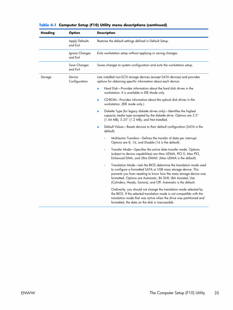
Table 4-1 Computer Setup (F10) Utility menu descriptions (continued)
Heading Option Description
Apply Defaultsand Exit
Restores the default settings defined in Default Setup.
Ignore Changesand Exit
Exits workstation setup without applying or saving changes.
Save Changesand Exit
Saves changes to system configuration and exits the workstation setup.
Storage DeviceConfiguration
Lists installed non-SCSI storage devices (except SATA devices) and providesoptions for obtaining specific information about each device:
● Hard Disk—Provides information about the hard disk drives in theworkstation. It is available in IDE Mode only.
● CD-ROM—Provides information about the optical disk drives in theworkstation. (IDE mode only.)
● Diskette Type (for legacy diskette drives only)—Identifies the highestcapacity media type accepted by the diskette drive. Options are 3.5"(1.44 MB), 5.25" (1.2 MB), and Not Installed.
● Default Values—Resets devices to their default configuration (SATA is thedefault).
◦ Multisector Transfers—Defines the transfer of data per interrupt.Options are 8, 16, and Disable (16 is the default).
◦ Transfer Mode—Specifies the active data transfer mode. Options(subject to device capabilities) are Max UDMA, PIO 0, Max PIO,Enhanced DMA, and Ultra DMA0. (Max UDMA is the default).
◦ Translation Mode—Lets the BIOS determine the translation mode usedto configure a formatted SATA or USB mass storage device. Thisprevents you from needing to know how the mass storage device wasformatted. Options are Automatic, Bit Shift, LBA Assisted, Use(Cylinders, Heads, Sectors), and Off. Automatic is the default.
Ordinarily, you should not change the translation mode selected bythe BIOS. If the selected translation mode is not compatible with thetranslation mode that was active when the drive was partitioned andformatted, the data on the disk is inaccessible.
ENWW The Computer Setup (F10) Utility 35
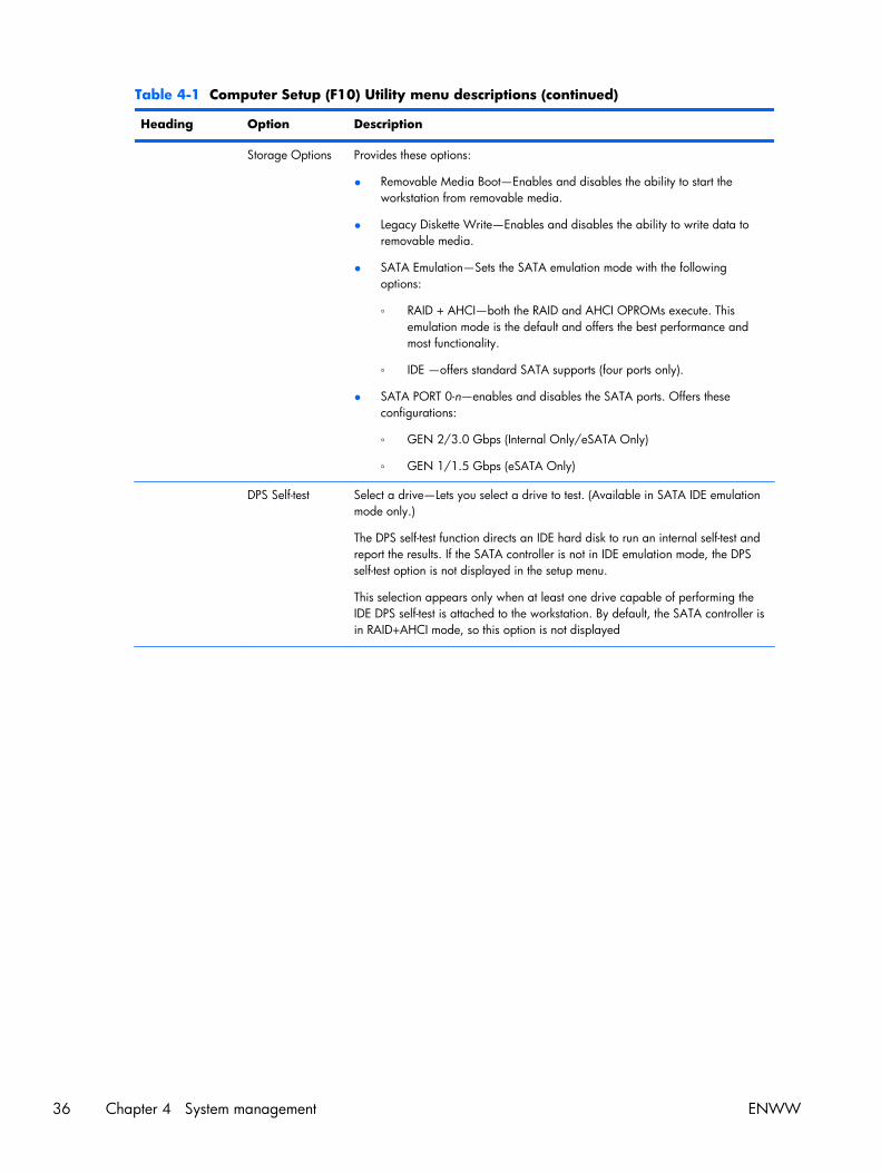
Table 4-1 Computer Setup (F10) Utility menu descriptions (continued)
Heading Option Description
Storage Options Provides these options:
● Removable Media Boot—Enables and disables the ability to start theworkstation from removable media.
● Legacy Diskette Write—Enables and disables the ability to write data toremovable media.
● SATA Emulation—Sets the SATA emulation mode with the followingoptions:
◦ RAID + AHCI—both the RAID and AHCI OPROMs execute. Thisemulation mode is the default and offers the best performance andmost functionality.
◦ IDE —offers standard SATA supports (four ports only).
● SATA PORT 0-n—enables and disables the SATA ports. Offers theseconfigurations:
◦ GEN 2/3.0 Gbps (Internal Only/eSATA Only)
◦ GEN 1/1.5 Gbps (eSATA Only)
DPS Self-test Select a drive—Lets you select a drive to test. (Available in SATA IDE emulationmode only.)
The DPS self-test function directs an IDE hard disk to run an internal self-test andreport the results. If the SATA controller is not in IDE emulation mode, the DPSself-test option is not displayed in the setup menu.
This selection appears only when at least one drive capable of performing theIDE DPS self-test is attached to the workstation. By default, the SATA controller isin RAID+AHCI mode, so this option is not displayed
36 Chapter 4 System management ENWW
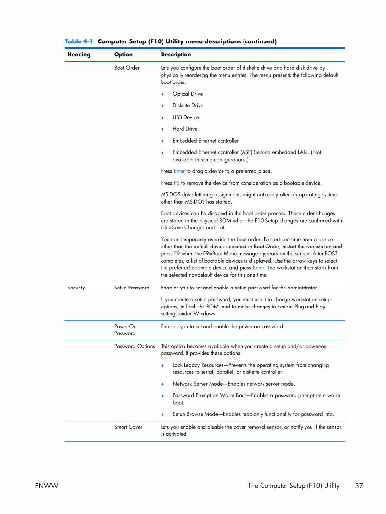
Table 4-1 Computer Setup (F10) Utility menu descriptions (continued)
Heading Option Description
Boot Order Lets you configure the boot order of diskette drive and hard disk drive byphysically reordering the menu entries. The menu presents the following defaultboot order:
● Optical Drive
● Diskette Drive
● USB Device
● Hard Drive
● Embedded Ethernet controller
● Embedded Ethernet controller (ASF) Second embedded LAN. (Notavailable in some configurations.)
Press Enter to drag a device to a preferred place.
Press F5 to remove the device from consideration as a bootable device.
MS-DOS drive lettering assignments might not apply after an operating systemother than MS-DOS has started.
Boot devices can be disabled in the boot order process. These order changesare stored in the physical ROM when the F10 Setup changes are confirmed withFile>Save Changes and Exit.
You can temporarily override the boot order. To start one time from a deviceother than the default device specified in Boot Order, restart the workstation andpress F9 when the F9=Boot Menu message appears on the screen. After POSTcompletes, a list of bootable devices is displayed. Use the arrow keys to selectthe preferred bootable device and press Enter. The workstation then starts fromthe selected nondefault device for this one time.
Security Setup Password Enables you to set and enable a setup password for the administrator.
If you create a setup password, you must use it to change workstation setupoptions, to flash the ROM, and to make changes to certain Plug and Playsettings under Windows.
Power-OnPassword
Enables you to set and enable the power-on password.
Password Options This option becomes available when you create a setup and/or power-onpassword. It provides these options:
● Lock Legacy Resources—Prevents the operating system from changingresources to serial, parallel, or diskette controller.
● Network Server Mode—Enables network server mode.
● Password Prompt on Warm Boot—Enables a password prompt on a warmboot.
● Setup Browse Mode—Enables read-only functionality for password info.
Smart Cover Lets you enable and disable the cover removal sensor, or notify you if the sensoris activated.
ENWW The Computer Setup (F10) Utility 37
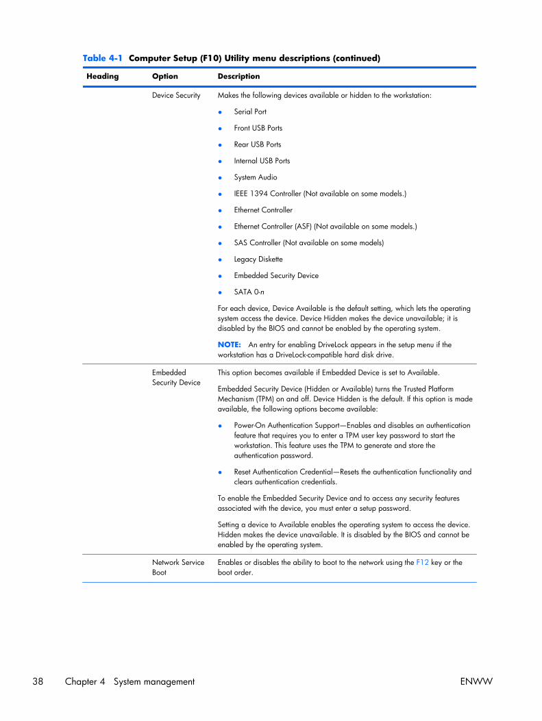
Table 4-1 Computer Setup (F10) Utility menu descriptions (continued)
Heading Option Description
Device Security Makes the following devices available or hidden to the workstation:
● Serial Port
● Front USB Ports
● Rear USB Ports
● Internal USB Ports
● System Audio
● IEEE 1394 Controller (Not available on some models.)
● Ethernet Controller
● Ethernet Controller (ASF) (Not available on some models.)
● SAS Controller (Not available on some models)
● Legacy Diskette
● Embedded Security Device
● SATA 0-n
For each device, Device Available is the default setting, which lets the operatingsystem access the device. Device Hidden makes the device unavailable; it isdisabled by the BIOS and cannot be enabled by the operating system.
NOTE: An entry for enabling DriveLock appears in the setup menu if theworkstation has a DriveLock-compatible hard disk drive.
EmbeddedSecurity Device
This option becomes available if Embedded Device is set to Available.
Embedded Security Device (Hidden or Available) turns the Trusted PlatformMechanism (TPM) on and off. Device Hidden is the default. If this option is madeavailable, the following options become available:
● Power-On Authentication Support—Enables and disables an authenticationfeature that requires you to enter a TPM user key password to start theworkstation. This feature uses the TPM to generate and store theauthentication password.
● Reset Authentication Credential—Resets the authentication functionality andclears authentication credentials.
To enable the Embedded Security Device and to access any security featuresassociated with the device, you must enter a setup password.
Setting a device to Available enables the operating system to access the device.Hidden makes the device unavailable. It is disabled by the BIOS and cannot beenabled by the operating system.
Network ServiceBoot
Enables or disables the ability to boot to the network using the F12 key or theboot order.
38 Chapter 4 System management ENWW
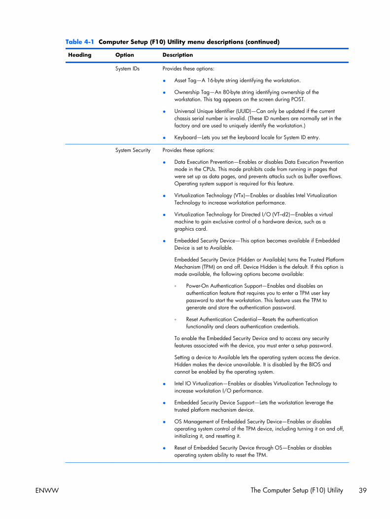
Table 4-1 Computer Setup (F10) Utility menu descriptions (continued)
Heading Option Description
System IDs Provides these options:
● Asset Tag—A 16-byte string identifying the workstation.
● Ownership Tag—An 80-byte string identifying ownership of theworkstation. This tag appears on the screen during POST.
● Universal Unique Identifier (UUID)—Can only be updated if the currentchassis serial number is invalid. (These ID numbers are normally set in thefactory and are used to uniquely identify the workstation.)
● Keyboard—Lets you set the keyboard locale for System ID entry.
System Security Provides these options:
● Data Execution Prevention—Enables or disables Data Execution Preventionmode in the CPUs. This mode prohibits code from running in pages thatwere set up as data pages, and prevents attacks such as buffer overflows.Operating system support is required for this feature.
● Virtualization Technology (VTx)—Enables or disables Intel VirtualizationTechnology to increase workstation performance.
● Virtualization Technology for Directed I/O (VT–d2)—Enables a virtualmachine to gain exclusive control of a hardware device, such as agraphics card.
● Embedded Security Device—This option becomes available if EmbeddedDevice is set to Available.
Embedded Security Device (Hidden or Available) turns the Trusted PlatformMechanism (TPM) on and off. Device Hidden is the default. If this option ismade available, the following options become available:
◦ Power-On Authentication Support—Enables and disables anauthentication feature that requires you to enter a TPM user keypassword to start the workstation. This feature uses the TPM togenerate and store the authentication password.
◦ Reset Authentication Credential—Resets the authenticationfunctionality and clears authentication credentials.
To enable the Embedded Security Device and to access any securityfeatures associated with the device, you must enter a setup password.
Setting a device to Available lets the operating system access the device.Hidden makes the device unavailable. It is disabled by the BIOS andcannot be enabled by the operating system.
● Intel IO Virtualization—Enables or disables Virtualization Technology toincrease workstation I/O performance.
● Embedded Security Device Support—Lets the workstation leverage thetrusted platform mechanism device.
● OS Management of Embedded Security Device—Enables or disablesoperating system control of the TPM device, including turning it on and off,initializing it, and resetting it.
● Reset of Embedded Security Device through OS—Enables or disablesoperating system ability to reset the TPM.
ENWW The Computer Setup (F10) Utility 39
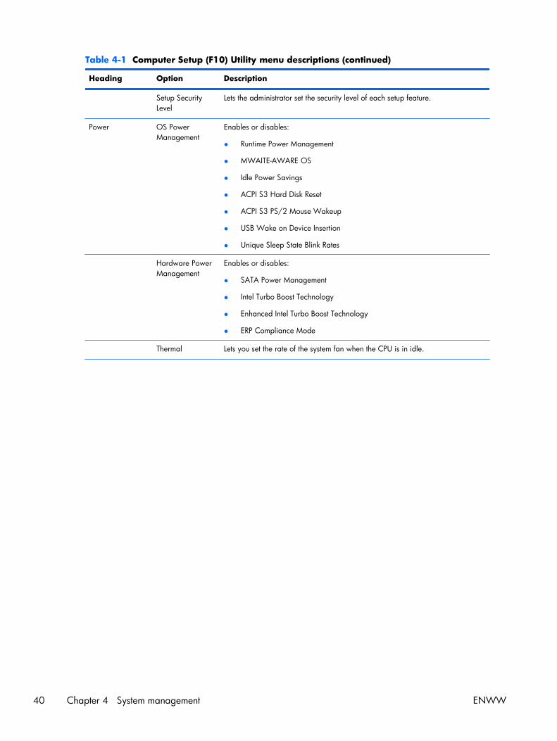
Table 4-1 Computer Setup (F10) Utility menu descriptions (continued)
Heading Option Description
Setup SecurityLevel
Lets the administrator set the security level of each setup feature.
Power OS PowerManagement
Enables or disables:
● Runtime Power Management
● MWAITE-AWARE OS
● Idle Power Savings
● ACPI S3 Hard Disk Reset
● ACPI S3 PS/2 Mouse Wakeup
● USB Wake on Device Insertion
● Unique Sleep State Blink Rates
Hardware PowerManagement
Enables or disables:
● SATA Power Management
● Intel Turbo Boost Technology
● Enhanced Intel Turbo Boost Technology
● ERP Compliance Mode
Thermal Lets you set the rate of the system fan when the CPU is in idle.
40 Chapter 4 System management ENWW
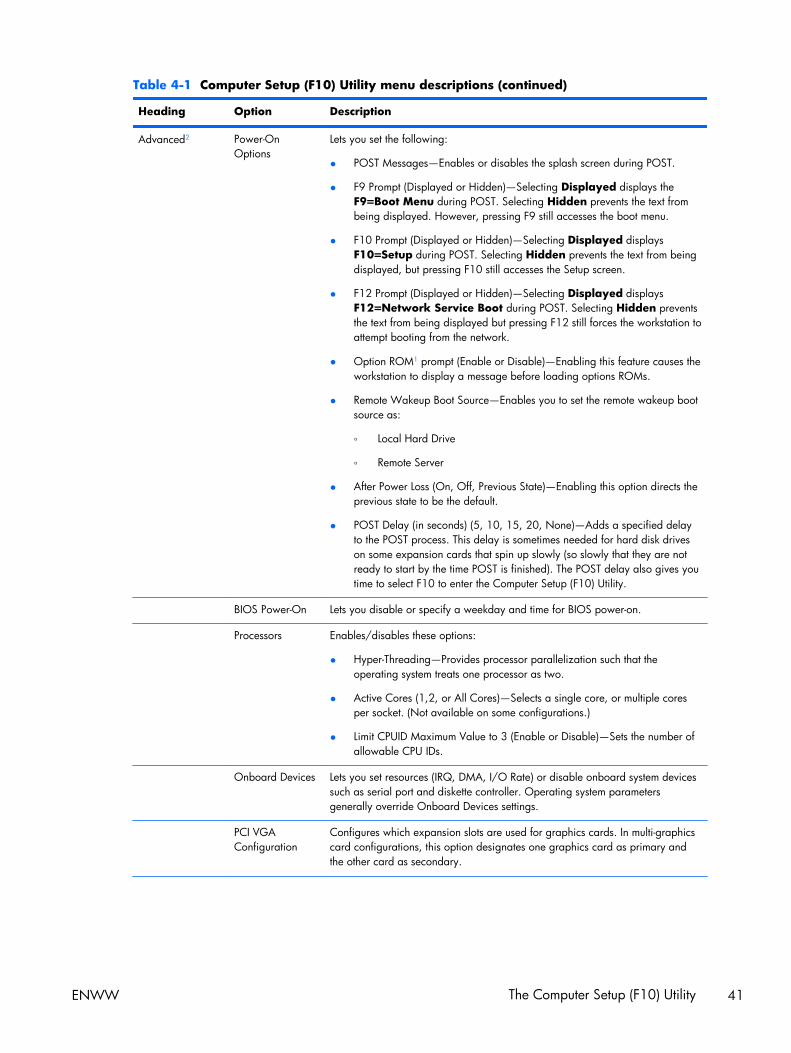
Table 4-1 Computer Setup (F10) Utility menu descriptions (continued)
Heading Option Description
Advanced2 Power-OnOptions
Lets you set the following:
● POST Messages—Enables or disables the splash screen during POST.
● F9 Prompt (Displayed or Hidden)—Selecting Displayed displays theF9=Boot Menu during POST. Selecting Hidden prevents the text frombeing displayed. However, pressing F9 still accesses the boot menu.
● F10 Prompt (Displayed or Hidden)—Selecting Displayed displaysF10=Setup during POST. Selecting Hidden prevents the text from beingdisplayed, but pressing F10 still accesses the Setup screen.
● F12 Prompt (Displayed or Hidden)—Selecting Displayed displaysF12=Network Service Boot during POST. Selecting Hidden preventsthe text from being displayed but pressing F12 still forces the workstation toattempt booting from the network.
● Option ROM1 prompt (Enable or Disable)—Enabling this feature causes theworkstation to display a message before loading options ROMs.
● Remote Wakeup Boot Source—Enables you to set the remote wakeup bootsource as:
◦ Local Hard Drive
◦ Remote Server
● After Power Loss (On, Off, Previous State)—Enabling this option directs theprevious state to be the default.
● POST Delay (in seconds) (5, 10, 15, 20, None)—Adds a specified delayto the POST process. This delay is sometimes needed for hard disk driveson some expansion cards that spin up slowly (so slowly that they are notready to start by the time POST is finished). The POST delay also gives youtime to select F10 to enter the Computer Setup (F10) Utility.
BIOS Power-On Lets you disable or specify a weekday and time for BIOS power-on.
Processors Enables/disables these options:
● Hyper-Threading—Provides processor parallelization such that theoperating system treats one processor as two.
● Active Cores (1,2, or All Cores)—Selects a single core, or multiple coresper socket. (Not available on some configurations.)
● Limit CPUID Maximum Value to 3 (Enable or Disable)—Sets the number ofallowable CPU IDs.
Onboard Devices Lets you set resources (IRQ, DMA, I/O Rate) or disable onboard system devicessuch as serial port and diskette controller. Operating system parametersgenerally override Onboard Devices settings.
PCI VGAConfiguration
Configures which expansion slots are used for graphics cards. In multi-graphicscard configurations, this option designates one graphics card as primary andthe other card as secondary.
ENWW The Computer Setup (F10) Utility 41

Table 4-1 Computer Setup (F10) Utility menu descriptions (continued)
Heading Option Description
Chipset/ Memory Enable/disable these options:
● PCI SERR# Generation (Enable or Disable)—Controls PCI SERR#generation for ill-behaved PCI add-in cards (that can generate SERR#spuriously).
● PCI VGA Palette Snooping (Enable or Disable)—Controls PCI VGA PaletteSnooping for compatibility purposes.
● Memory Mode Interleave—Sets interleave mode for dual socketworkstations.
Device Options Lets you set the following device options:
● Num Lock State at Power-On (On or Off)
● S5 Wake-on-LAN (Enable or Disable)
● Multiprocessor (Activates a single core.)
● Unique Sleep State Blink Rates (Enable or Disable)
● Internal speaker
● Monitor Tracking (Enable or Disable)
● NIC PXE Option ROM1 Download (Enable or Disable)
● SAS Option ROM1 Download (Enable or Disable) (Not available on someworkstations.)
● SATA RAID Option ROM1 Download (Enable or Disable)
1 Available on selected models2 These options should be used by advanced users only
42 Chapter 4 System management ENWW
Workstation managementThis section summarizes capabilities, features, and key components of workstation management,including:
Topics
Initial workstation configuration and deployment on page 44
Installing a remote system on page 44
Replicating the setup on page 45
Updating and managing software on page 47
HP Client Manager Software on page 47
Altiris Client Management Solutions on page 47
System Software Manager on page 49
Proactive Change Notification on page 49
Subscriber's Choice on page 49
ROM Flash on page 50
FailSafe Boot Block ROM on page 51
Workstation security on page 52
Fault notification and recovery on page 62
Dual-state power button on page 63
NOTE: Support for specific features described in this guide can vary by model and software version.
ENWW Workstation management 43
Initial workstation configuration and deploymentThe workstation includes a preinstalled system software image. After a brief software unbundlingprocess, the workstation is ready to use.
If you prefer to replace the preinstalled software image with a customized set of system and applicationsoftware, several methods are available for deploying a customized software image, including:
● Installing additional software applications after unbundling the preinstalled software image
● Using a disk cloning process to copy the contents from one hard disk drive to another
The Restore Plus! CD, ROM-based setup, and ACPI hardware provide further assistance with recoveryof system software, configuration management and troubleshooting, and power management.
Support for specific features described in this guide can vary by model and software version.
The best deployment method depends on the information technology environment and processes.
Installing a remote systemRemote system installation enables starting and setting up the workstation using software andconfiguration information on a network server. This feature provides a useful system setup andconfiguration tool for the following tasks:
● Deploying a software image on new PCs
● Formatting a hard disk drive
● Installing application software or drivers
● Updating the operating system, application software, or drivers
To initiate a remote system installation, press F12 when F12=Network Service Boot appears in thelower right corner of the HP logo screen. Follow the onscreen instructions to continue the installationprocess. The default boot order is a BIOS configuration setting that can be changed to always attempta PXE boot.
44 Chapter 4 System management ENWW
Replicating the setupThis section provides information about replicating the workstation setup.
Copying a setup configuration to a single workstation
CAUTION: A setup configuration is model-specific. File system corruption can result if source andtarget workstations are not the same model.
To copy a setup configuration:
1. Select a setup configuration to copy, and then restart the workstation.
2. As soon as the workstation powers on, press and hold F10 until you enter the Computer Setup(F10) Utility. If necessary, press Enter to bypass the title screen.
NOTE: If you do not press F10 at the appropriate time, you must restart the workstation, andthen press and hold F10 again to access the utility.
If you are using a PS/2 keyboard, you might see a keyboard error message. Disregard it.
3. Select File>Replicated Setup>Save to Removable Media. Follow the instructions on thescreen to create the configuration diskette or USB media device.
4. Power off the workstation you are configuring and insert the configuration diskette into the diskettedrive or USB media device.
5. Power on the workstation you are configuring.
6. Press and hold the F10 key until you enter the Computer Setup (F10) Utility. If necessary, pressEnter to bypass the title screen.
7. Select File>Replicated Setup>Restore from Removable Media, and then follow theinstructions on the screen.
8. Restart the workstation when the configuration is complete.
ENWW Workstation management 45

Copying a setup configuration to multiple workstations
CAUTION: A setup configuration is model-specific. If source and target workstations are not thesame model, file system corruption can result. For example, do not copy the setup configuration froman HP xw8600 Workstation to an HP Z400 Workstation.
This method takes longer to prepare the configuration diskette, but copying the configuration to targetworkstations is fast.
A bootable diskette is required for this procedure. If Windows XP is not available to create a bootablediskette, use the method for copying to a single workstation instead (see Copying a setup configurationto a single workstation on page 45).
1. Create a bootable diskette or USB media device.
2. Select a setup configuration to copy.
3. If you are using a diskette or USB storage device, insert it now.
4. Restart the workstation.
5. As soon as the workstation powers on, press and hold F10 until you enter the Computer Setup(F10) Utility. If necessary, press Enter to bypass the title screen.
NOTE: If you do not press the F10 key at the appropriate time, you must restart the workstation,and then press and hold the F10 key again to access the utility.
If you are using a PS/2 keyboard, you might see a keyboard error message. Disregard it.
6. Select File>Replicated Setup>Save to Removable Media, and follow the instructions onthe screen to create the configuration diskette or USB media device.
7. Download a BIOS utility for replicating setup (repset.exe), and copy it to the configuration disketteor USB media device. To obtain this utility, see http://www.hp.com/support/files.
8. Enter the model number of the workstation.
9. On the configuration diskette, create an autoexec.bat file containing repset.exe and cpqsetup.txt.
10. Power off the workstation you are configuring, insert the configuration diskette or USB device, andthen power on the workstation. The configuration utility runs automatically.
11. When the configuration is complete, restart the workstation.
46 Chapter 4 System management ENWW
Updating and managing softwareHP provides several tools for managing and updating software on desktops and workstations:
● HP Client Manager Software
● System Software Manager
● Altiris Client Management Solutions
● Proactive Change Notification
● Subscriber’s Choice
HP Client Manager SoftwareThe HP Client Manager Software offers these services:
● Detailed views of hardware inventory for asset management
● PC health-check monitoring and diagnostics
● Proactive notification of changes in the hardware environment
● Web-accessible reporting of business-critical details such as thermal warnings and memory alerts
● Remote updating of system software such as device drivers and ROM BIOS
● Remote changing of boot order
● Configuration of system BIOS settings
The HP Client Management Solutions (CMS), available for download from http://www.hp.com/go/easydeploy, are standards-based solutions for managing and controlling workstations in a networkedenvironment.
For more information about the HP Client Manager, see http://www.hp.com/go/ssm.
Altiris Client Management SolutionsAltiris and HP have partnered to provide comprehensive, tightly integrated systems managementsolutions to reduce the cost of owning HP client PCs.
The HP CMS is the foundation for additional Altiris Client Management Solutions that address thefollowing topics.
● Inventory and asset management
● Deployment and migration
● Help desk and problem resolution
● Software and operations management
For more information about the following topics, go to http://www.hp.com/go/ssm.
● How HP CMS works
● Which solutions are compatible with the operating system
● How to download a fully functional, 30-day evaluation version of Altiris solutions
ENWW Workstation management 47

HP SoftPaq Download ManagerHP SoftPaq Download Manager is a free, easy-to-use interface for locating and downloading softwareupdates for the HP client PC models in your environment. By specifying your models, operating system,and language, you can quickly locate, sort, and select the softpaqs you need. To download HP SoftPaqDownload Manager, visit http://h20331.www2.hp.com/Hpsub/cache/509658-0-0-225-121.html.
48 Chapter 4 System management ENWW

System Software ManagerSystem Software Manager (SSM) is a utility available on Windows workstations that lets you updatesystem-level software on multiple systems simultaneously. When executed on a PC client system, SSMdetects hardware and software versions and then updates the software from a central repository,known as a file store. Driver versions supported by SSM are noted with a special icon on the software,the driver download Web site, and on the Support Software CD.
To download the utility or to obtain more information about SSM, see http://www.hp.com/go/ssm.
Proactive Change NotificationThe Proactive Change Notification application uses the Subscriber's Choice Web site to:
● Send Proactive Change Notification (PCN) e-mail informing you up to 60 days in advance ofhardware and software changes to most commercial workstations and servers
● Send you e-mail containing customer bulletins, customer advisories, customer notes, and driveralerts for most commercial workstations and servers
You can create a profile to ensure you receive only the information relevant to the specific ITenvironment.
To learn more about the PCN application and to create a custom profile, see Subscriber's Choiceon page 49.
Subscriber's ChoiceSubscriber’s Choice is a client-based service from HP that supplies you with personalized product tips,feature articles, and driver and support alerts and notifications based on the profile.
Subscriber’s Choice Driver and Support Alerts and Notifications delivers e-mail notifying you that theinformation you subscribed to in the profile is available for review and retrieval.
To learn more about Subscriber’s Choice and create a custom profile, see:
http://www.hp.com/go/subscriberschoice
ENWW Workstation management 49
ROM FlashHP workstations include a programmable flash ROM. By establishing a setup password in theComputer Setup (F10) Utility, you can protect the ROM from being inadvertently updated oroverwritten. This function is important to ensure the operating integrity of the workstation.
To upgrade the ROM, download the latest SoftPaq images from http://www.hp.com/support/workstation_swdrivers.
For maximum ROM protection, establish a setup password. The setup password prevents unauthorizedROM upgrades. SSM lets you create the setup password on several workstations simultaneously.
Remote ROM Flash
Remote ROM Flash lets system administrators safely upgrade the ROM on remote HP workstations froma centralized network management console. This permits consistent deployment and greater control ofHP PC ROM images over the network.
To use Remote ROM Flash, the workstation must be powered on, or turned on using Remote Wakeup.
For more information about Remote ROM Flash and HPQFlash, see the HP Client Manager Software orSystem Software Manager sections at http://www.hp.com/go/ssm.
HPQFlash
The HPQFlash utility locally updates or restores the system ROM on PCs using a Windows operatingsystem. For more information about HPQFlash, see http://www.hp.com/go/ssm, and enter the nameof the workstation.
50 Chapter 4 System management ENWW

FailSafe Boot Block ROMThe FailSafe Boot Block ROM enables system recovery in the unlikely event of a ROM flash failure. Forexample, if a power failure occurs during a ROM upgrade, the Boot Block uses a flash-protectedsection of the ROM to verify a valid system ROM flash when power is restored to the workstation.
If the system ROM is valid, the workstation starts normally.
If the system ROM fails the validation check, the FailSafe Boot Block ROM provides enough support tostart the workstation from a BIOS image CD created from a SoftPaq. The BIOS image CD programs thesystem ROM with a valid image.
When Boot Block detects an invalid system ROM, the workstation power LED blinks red eight times andthe workstation beeps eight times; then the workstation pauses for two seconds. On some models, aBoot Block recovery mode message appears.
In preparation for system recovery, use the BIOS CD media file in the SoftPaq to create a BIOS imageCD.
Recovering the workstation from Boot Block Recovery mode
To recover the workstation after it enters Boot Block recovery mode:
1. If there is media in the diskette or optical disk drives, remove it.
2. Insert a BIOS image CD into the CD drive.
You can also use USB media such as an HP DriveKey.
3. Power off, then power on the workstation.
If no BIOS image CD or USB media is found, you are prompted to insert one and restart theworkstation.
If a setup password has been established, the Caps Lock light illuminates and you are promptedfor the password.
4. Enter the setup password.
If the workstation starts from the CD or USB media and successfully reprograms the ROM, threekeyboard lights illuminate. A rising-tone series of beeps also signals successful recovery.
5. Remove the CD or USB media and power off the workstation.
6. Restart the workstation.
ENWW Workstation management 51
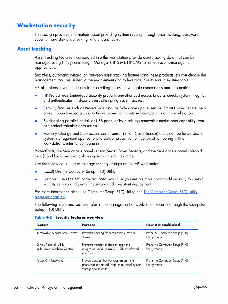
Workstation securityThis section provides information about providing system security through asset tracking, passwordsecurity, hard disk drive locking, and chassis locks.
Asset tracking
Asset tracking features incorporated into the workstation provide asset tracking data that can bemanaged using HP Systems Insight Manager (HP SIM), HP CMS, or other systems-managementapplications.
Seamless, automatic integration between asset tracking features and these products lets you choose themanagement tool best suited to the environment and to leverage investments in existing tools.
HP also offers several solutions for controlling access to valuable components and information:
● HP ProtectTools Embedded Security prevents unauthorized access to data, checks system integrity,and authenticates third-party users attempting system access.
● Security features such as ProtectTools and the Side access panel sensor (Smart Cover Sensor) helpprevent unauthorized access to the data and to the internal components of the workstation.
● By disabling parallel, serial, or USB ports, or by disabling removable-media boot capability, youcan protect valuable data assets.
● Memory Change and Side access panel sensor (Smart Cover Sensor) alerts can be forwarded tosystem management applications to deliver proactive notification of tampering with aworkstation’s internal components.
ProtectTools, the Side access panel sensor (Smart Cover Sensor), and the Side access panel solenoidlock (Hood Lock) are available as options on select systems.
Use the following utilities to manage security settings on the HP workstation:
● (Local) Use the Computer Setup (F10) Utility.
● (Remote) Use HP CMS or System SSM, which let you use a simple command-line utility to controlsecurity settings and permit the secure and consistent deployment.
For more information about the Computer Setup (F10) Utility, see The Computer Setup (F10) Utilitymenu on page 34.
The following table and sections refer to the management of workstation security through the ComputerSetup (F10) Utility
Table 4-2 Security features overview
Feature Purpose How it is established
Removable Media Boot Control Prevents booting from removable mediadrives
From the Computer Setup (F10)Utility menu
Serial, Parallel, USB,or Infrared Interface Control
Prevents transfer of data through theintegrated serial, parallel, USB, or infraredinterface
From the Computer Setup (F10)Utility menu
Power-On Password Prevents use of the workstation until thepassword is entered (applies to initial systemstartup and restarts)
From the Computer Setup (F10)Utility menu
52 Chapter 4 System management ENWW

Table 4-2 Security features overview (continued)
Feature Purpose How it is established
Setup Password Prevents reconfiguration of the workstation(use of the Setup utility) until the password isentered
From the Computer Setup (F10)Utility menu
Network Server Mode Provides unique security features forworkstations used as servers
From the Computer Setup (F10)Utility menu
SATA hard disk drive security
HP workstations include the HP DriveLock facility for SATA hard disk drives to prevent unauthorizedaccess to data.
WARNING! Enabling DriveLock can render a SATA hard disk drive permanently inaccessible if themaster password is lost or forgotten. No method exists to recover the password or access the data.
DriveLock has been implemented as an extension to Computer Setup (F10) functions. It is only availablewhen hard disk drives that support the ATA security command set are detected. On HP workstations, itis not available when the SATA emulation mode is RAID+AHCI or RAID.
DriveLock is for HP customers for whom data security is a paramount concern. For such customers, thecost of a hard disk drive and the loss of the data stored on it is inconsequential when compared to thedamage that could result from unauthorized access to its contents.
To balance this level of security with the need to address the issue of a forgotten password, the HPimplementation of DriveLock employs a two-password security scheme. One password is intended to beset and used by a system administrator, while the other is typically set and used by the user.
No "back door" can be used to unlock the drive if both passwords are lost. Therefore, DriveLock ismost safely used when the data contained on the hard disk drive is replicated on a corporateinformation system or is regularly backed up.
If both DriveLock passwords are lost, the hard disk drive is rendered unusable. For users who do not fitthe previously defined customer profile, this might not be acceptable. For users who fit this profile, itmight be a tolerable risk, given the nature of the data stored on the hard disk drive.
ENWW Workstation management 53
DriveLock applications
The most practical use of DriveLock is in a corporate environment. The system administrator would beresponsible for configuring the hard disk drive, which involves setting the DriveLock master passwordand a temporary user password. If you forget the user password or if the equipment is passed on toanother employee, the master password can be used to reset the user password and regain access tothe hard disk drive.
HP recommends that corporate system administrators who enable DriveLock also establish a corporatepolicy for setting and maintaining master passwords. This prevents situation in which an employee setsboth DriveLock passwords before leaving the company. This scenario leaves the hard disk driveunusable and forces its replacement. Likewise, system administrators who do not set a master passwordmight find themselves locked out of a hard disk drive and unable to perform routine checks forunauthorized software, other asset control functions, and support.
For users with less stringent security requirements, HP does not recommend enabling DriveLock. Users inthis category include personal users, or users who do not maintain sensitive data on their hard diskdrives as a common practice. For these users, the potential loss of a hard disk drive resulting fromforgetting both passwords is much greater than the value of the data DriveLock protects.
Create an administrator-only setup password to restrict access to Computer Setup (F10) and DriveLock.This keeps users from enabling DriveLock.
Using DriveLock
When DriveLock detects hard disk drives that support the ATA security command, a DriveLock menuitem appears under the Security menu in the Computer Setup (F10) menu. This presents you withoptions to set the master password and to enable DriveLock. You must provide a user password toenable DriveLock. Because a system administrator typically performs the initial configuration ofDriveLock, set a master password first.
HP recommends that system administrators set a master password whether they plan to enableDriveLock or not. This lets administrators modify DriveLock settings if the drive is locked in the future.After the master password is set, the system administrator can enable DriveLock or leave it disabled.
If a locked hard disk drive is present, POST requires a password to unlock the device. If a power-onpassword is set and it matches the device’s user password, POST does not prompt the user to re-enterthe password. Otherwise, the user is prompted to enter a DriveLock password.
For a cold start, use the master or user password. For a warm start, enter the same password used tounlock the drive during the preceding cold start.
Users have two attempts to enter a correct password. During cold start, if neither attempt succeeds,POST continues but the drive remains inaccessible. During a warm-start or restart from Windows, ifneither attempt succeeds, POST halts and the user is instructed to cycle power.
54 Chapter 4 System management ENWW
Enabling DriveLock
To enable and set the DriveLock user password:
1. Power on or restart the workstation.
2. As soon as the workstation is powered on, press and hold F10 until you enter the Computer Setup(F10) Utility. Press Enter to bypass the title screen, if necessary.
If you do not press F10 at the appropriate time, you must restart the workstation, and then pressand hold F10 again to access the utility.
If you are using a PS2 keyboard, you might see a keyboard error message. Disregard it.
3. Select Security>DriveLock Security.
4. For each DriveLock-capable drive, select a drive by pressing F10 to accept.
5. Under Enable/Disable DriveLock options, select Enable, and then press F10 to enable DriveLockfor a specific drive.
CAUTION: Forgetting the DriveLock password renders the drive unusable.
6. Enter a new user password, and then press F10 to accept. This password may be 1 to 32characters long.
7. Enter the password again in the Enter New Password Again field. If you forget this password, thedrive is rendered permanently disabled.
8. Select File>Save Changes and Exit, and then press F10. After you press F10, the workstationperforms a cold start before invoking the DriveLock function.
You can also use this process to set the DriveLock master password by selecting Master in Step5.
When the workstation starts, you are prompted to enter the DriveLock password for eachDriveLock-capable drive for which you have set a password. You have two attempts to enter thepassword correctly. If the password is not entered correctly, the workstation attempts to startanyway. However, the boot process most likely fails because data from a locked drive cannot beaccessed.
In a single drive workstation, if the drive has DriveLock enabled, the workstation might not be ableto boot to the operating system, and might try to boot from the network or from another storagedevice (depending on the boot ordering options). Regardless of the outcome of the start attempts,the drive-locked drive remains inaccessible without the DriveLock password.
In a two-drive workstation that has a boot drive and a data drive, you can apply the DriveLockfeature to the data drive only. In this case, the workstation can always start, but the data drive isaccessible only when the DriveLock password is entered.
Cold starts require that you enter DriveLock passwords. However, DriveLock passwords are alsorequired for warm starts. For example, if you boot to DOS and press Ctrl+Alt+Del, you must enterthe DriveLock password before the workstation completes the next start cycle. This warm-startbehavior is consistent with the DriveLock feature.
ENWW Workstation management 55

Password security
The power-on password prevents unauthorized use of the workstation by requiring entry of a passwordto access applications or data when the workstation is powered on or restarted. The setup passwordspecifically prevents unauthorized access to the Computer Setup (F10) Utility and can also override thepower-on password. When prompted for the power-on password, entering the setup password insteadenables access to the workstation.
You can establish a network-wide setup password, which lets the system administrator log in to allnetwork systems to perform maintenance without having to know the power-on password.
Establishing a setup password using Computer Setup (F10) Utility
Establishing a setup password through the Computer Setup (F10) Utility prevents reconfiguration of theworkstation (through the use of the Computer Setup (F10) Utility) until the password is entered.
To establish a setup password using the Computer Setup (F10) menu:
1. Power on or restart the workstation.
2. As soon as the workstation is powered on, press and hold F10 until you enter the Computer Setup(F10) Utility. Press Enter to bypass the title screen, if necessary.
If you do not press F10 at the appropriate time, you must restart the workstation, and then pressand hold F10 again to access the utility.
If you are using a PS/2 keyboard, you might see a keyboard error message. Disregard it.
3. Select Security>Setup Password and then follow the onscreen instructions.
4. Before exiting, select File>Save Changes and Exit.
56 Chapter 4 System management ENWW

Establishing a power-on password using workstation setup
Establishing a power-on password through the Computer Setup (F10) Utility prevents access to theworkstation when power is connected, unless you specify the password. When a power-on password isset, the Computer Setup (F10) Utility presents Password Options in the Security menu. The passwordoptions include Network Server Mode and Password Prompt on Warm Boot.
When Network Server Mode is disabled, you must enter the password when the workstation ispowered on, when the key icon appears on the monitor. When Password Prompt on Warm Bootis enabled, you must enter the password. The password must also be entered each time the workstationis restarted. When Network Server Mode is enabled, the password prompt is not presented duringPOST, but an attached PS/2 keyboard remains locked until you enter the power-on password.
To enable Network Server Mode, you must set a power-on password under Advanced>PasswordOptions. This option lets the workstation start without requiring the power-on password, although thekeyboard and mouse remain locked until you enter the password. The keyboard LEDs flash in a rotatingpattern when the workstation is in locked mode.
To establish a power-on password through the Computer (F10) menu:
1. Power on or restart the workstation.
2. As soon as the workstation is powered on, press and hold F10 until you enter the Computer Setup(F10) Utility. Press Enter to bypass the title screen, if necessary.
If you do not press F10 at the appropriate time, you must restart the workstation and then pressand hold F10 again to access the utility.
If you are using a PS/2 keyboard, you might see a keyboard error message. Disregard it.
3. Select Security>Power-On Password and then follow the onscreen instructions.
4. Before exiting, select File>Save Changes and Exit.
Entering a power-on password
To enter a power-on password:
1. Restart the workstation.
2. When the key icon appears on the monitor, enter the current password, and then press Enter.
Type carefully. For security reasons, the characters you enter do not appear on the screen.
If you enter the password incorrectly, a broken key icon appears. Try again. After three unsuccessfultries, you will enter the F10 setup screen with read-only permission. (See the Setup Browse Mode optionunder the Power-On options.)
ENWW Workstation management 57
Entering a setup password
If a setup password has been established on the workstation, you will be prompted to enter it each timeyou run the Computer Setup (F10) Utility.
To enter a setup password:
1. Restart the workstation.
2. As soon as the workstation is powered on, press and hold F10 until you enter the Computer Setup(F10) Utility. Press Enter to bypass the title screen, if necessary.
If you do not press F10 at the appropriate time, you must restart the workstation and press andhold F10 again to access the utility.
If you are using a PS/2 keyboard, you might see a keyboard error message. Disregard it.
3. When the key icon appears on the monitor, enter the setup password, and press Enter.
Type carefully. For security reasons, the characters you enter do not appear on the screen.
If you enter the password incorrectly, a broken key icon appears. Try again. After three unsuccessfultries, you must restart the workstation before you can continue.
Changing a power-on or setup password
To change a power-on or setup password:
1. Restart the workstation.
2. To change the power-on password, go to step 4.
3. To change the setup password, as soon as the workstation is powered on, press and hold F10until you enter the Computer Setup (F10) Utility. Press Enter to bypass the title screen, if necessary.
If you do not press F10 at the appropriate time, you must restart the workstation, and then pressand hold the F10 key again to access the utility.
If you are using a PS/2 keyboard, you might see a keyboard error message. Disregard it.
4. When the key icon appears, enter the current password, a slash (/) or alternative delimitercharacter, the new password, another slash (/) or alternative delimiter character, and the newpassword again as shown:
current password/new password/new password
For information about the alternative delimiter characters, see National keyboard delimitercharacters on page 59.
Type carefully. For security reasons, the characters you enter do not appear on the screen.
5. Press Enter.
The new password takes effect the next time you power on the workstation.
The power-on and setup passwords can also be changed using the Security options in the ComputerSetup (F10) Utility.
58 Chapter 4 System management ENWW
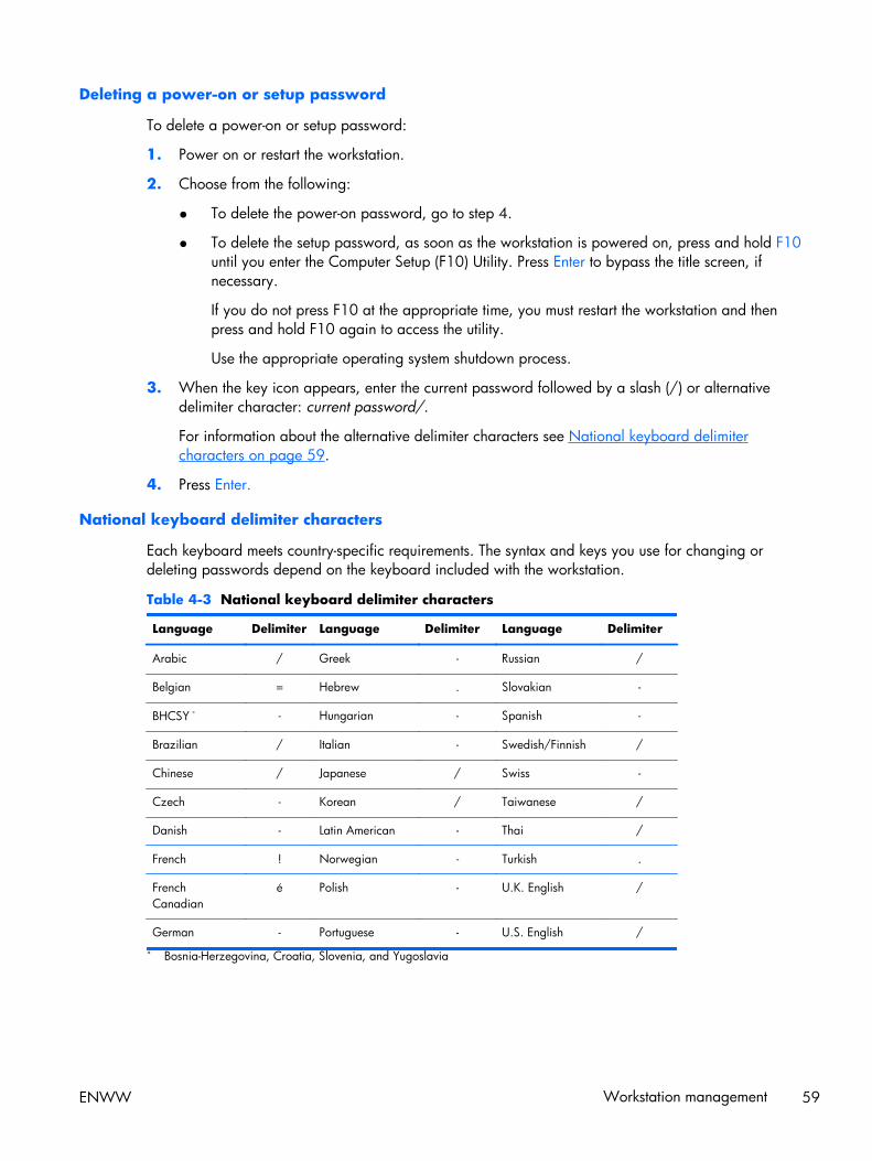
Deleting a power-on or setup password
To delete a power-on or setup password:
1. Power on or restart the workstation.
2. Choose from the following:
● To delete the power-on password, go to step 4.
● To delete the setup password, as soon as the workstation is powered on, press and hold F10until you enter the Computer Setup (F10) Utility. Press Enter to bypass the title screen, ifnecessary.
If you do not press F10 at the appropriate time, you must restart the workstation and thenpress and hold F10 again to access the utility.
Use the appropriate operating system shutdown process.
3. When the key icon appears, enter the current password followed by a slash (/) or alternativedelimiter character: current password/.
For information about the alternative delimiter characters see National keyboard delimitercharacters on page 59.
4. Press Enter.
National keyboard delimiter characters
Each keyboard meets country-specific requirements. The syntax and keys you use for changing ordeleting passwords depend on the keyboard included with the workstation.
Table 4-3 National keyboard delimiter characters
Language Delimiter Language Delimiter Language Delimiter
Arabic / Greek - Russian /
Belgian = Hebrew . Slovakian -
BHCSY * - Hungarian - Spanish -
Brazilian / Italian - Swedish/Finnish /
Chinese / Japanese / Swiss -
Czech - Korean / Taiwanese /
Danish - Latin American - Thai /
French ! Norwegian - Turkish .
FrenchCanadian
é Polish - U.K. English /
German - Portuguese - U.S. English /
* Bosnia-Herzegovina, Croatia, Slovenia, and Yugoslavia
ENWW Workstation management 59

Clearing passwords
If you forget the password, you cannot access the workstation.
For instructions about clearing passwords, see Configuring password security and resetting CMOSon page 216.
Chassis security
Side access panel sensor (Smart Cover Sensor) (optional)
The optional Side access panel sensor is a combination of hardware and software technology that canalert you when the workstation side access panel has been removed (if the sensor has been configuredin the Computer Setup (F10) Utility).
The three levels of Side access panel sensor protection are shown in the following table:
Table 4-4 Side access panel sensor protection levels
Level Setting Description
Level 0 Disabled Side access panel sensor * is disabled (default).
Level 1 Notify User When the workstation restarts, a message appears indicating that theworkstation side access panel has been removed.
Level 2 Setup Password When the workstation is restarted, a message appears indicating that theworkstation side access panel has been removed. You must enter the setuppassword to continue.
* Side access panel sensor settings can be changed using the Computer Setup (F10) Utility.
Setting the side access panel sensor protection level
To set the side access panel sensor protection level:
1. Power on or restart the workstation.
2. As soon as the workstation is powered on, press and hold the F10 key until you enter theComputer Setup (F10) Utility. Press Enter to bypass the title screen, if necessary.
NOTE: If you do not press the F10 key at the appropriate time, you must restart the workstation,and then press and hold the F10 key again to access the Computer Setup (F10) Utility.
If you are using a PS/2 keyboard, you might see a keyboard error message. Disregard it.
3. Select Security>Smart Cover>Cover Removal Sensor, and follow the onscreeninstructions.
4. Before exiting, select File>Save Changes and Exit.
60 Chapter 4 System management ENWW

Side access panel solenoid lock (optional)
The side access panel solenoid locks the side access panel to the chassis. The solenoid is controlled bya local or remote signal.
To lock the solenoid, set a password for the solenoid lock in the Computer Setup (F10) Utility. To unlockthe solenoid, remove the solenoid lock password in the Computer Setup (F10) Utility.
The solenoid lock FailSafe Key–available from HP–is is a device for manually disabling the solenoidlock. You will need the FailSafe Key in case of forgotten password, power loss, or workstationmalfunction.
ENWW Workstation management 61
Cable lock (optional)
To prevent theft, the rear chassis panel of the workstation accommodates a keyed cable lock. This cablelock attaches to the chassis and secures it to the work area.
Fault notification and recoveryFault notification and recovery features combine innovative hardware and software technology toprevent the loss of critical data and minimize unplanned downtime.
If the workstation is connected to a network that is managed by HP CMS, the workstation sends a faultnotice to the network management application. With HP CMS, you can also remotely schedulediagnostics to run on managed PCs and create a summary report of failed tests.
Drive Protection System
The Drive Protection System (DPS) is a diagnostic tool built into hard disk drives and is installed in selectHP workstations. The DPS helps diagnose problems that might result in unwarranted hard disk drivereplacement.
When HP workstations are built, each installed hard disk drive is tested using the DPS, and apermanent record of key information is written onto each drive. Every time the DPS is run, test resultsare written to the hard disk drive. The service provider can use this information to help diagnoseconditions that required you to run the DPS software.
ECC fault prediction
When the workstation encounters an excessive number of error checking and correcting (ECC) memoryerrors, it displays a local alert message. This message contains information about the errant DIMM,enabling you to take action before you experience noncorrectable memory errors. ECC DIMMs arestandard on this workstation.
Thermal sensors
Several thermal sensors in the HP Workstation regulate workstation fans to maintain an acceptable,efficient chassis temperature.
62 Chapter 4 System management ENWW
Dual-state power buttonWith ACPI enabled, the power button can function as an on/off switch or as a button. This feature doesnot completely turn off power, but instead causes the workstation to enter a low-power standby state.This lets you go to standby without closing applications or return to the same operational state withoutany data loss.
Changing the power button configuration
To change the power button configuration:
1. Select Start, and then select Control Panel>Power Options.
2. In Power Options Properties, select the Advanced tab.
3. In the Power Button section, select Hibernate.
NOTE: Hibernate must be enabled in the Hibernate tab.
After configuring the power button to function as a button, you can press the power button to put theworkstation in a very low power state. Press the button again to bring the workstation out of this lowpower state to full power state. To completely turn off power to the workstation, press and hold thepower button for four seconds.
CAUTION: Do not use the power button to power off the workstation unless the system is notresponding; turning off the power without operating system interaction can cause data loss.
ENWW Workstation management 63
5 Replacing components
This chapter presents removal and installation procedures for most internal workstation components. Itincludes these topics:
Topics
Warnings and cautions on page 65
Service considerations on page 66
Customer self-repair on page 71
Removing and installing components on page 72
Product recycling on page 163
64 Chapter 5 Replacing components ENWW

Warnings and cautionsWARNING! Any surface or area of the equipment marked with this symbol indicates thepresence of a hot surface or hot component. If this surface is contacted, the potential for injury exists.To reduce the risk of injury from a hot component, let the surface cool before touching.
WARNING! Any surface or area of the equipment marked with this symbol indicates thepresence of an electrical shock hazard. To reduce the risk of injury from electrical shock, do not openany enclosed area marked with this symbol.
WARNING! To reduce the risk of electric shock or damage to your equipment:
— Do not disable the power cord grounding plug. The grounding plug is an important safety feature.
— Plug the power cord in a grounded (earthed) outlet that is easily accessible at all times.
— Disconnect power from the equipment by unplugging the power cord from the electrical outlet.
WARNING! To reduce the risk of serious injury, read the Safety & Comfort Guide. It describesproper workstation setup, posture, health, and work habits for computer users, and provides importantelectrical and mechanical safety information. This guide is located at http://www.hp.com/ergo.
WARNING! If a product is shipped in packaging marked with this symbol, , the product mustalways be lifted by two persons to avoid personal injury due to product weight.
CAUTION: Static electricity can damage the electronic components of the workstation. Beforebeginning these procedures, be sure you discharge static electricity by briefly touching a groundedmetal object.
CAUTION: Observe the following cautions when removing or replacing a processor:
— Installing a processor incorrectly can damage the system board. Contact an HP authorized reselleror service provider to install the processor. If you plan to install the processor yourself, read all of theinstructions carefully before you begin.
— Failure to follow the workstation preparation instructions can result in an improperly installedprocessor, causing extensive workstation damage.
— Processor socket pins are delicate and bend easily. Use extreme care when placing the processor inthe socket.
CAUTION: To prevent damage to the workstation, observe the following Electrostatic Discharge(ESD) precautions while performing the system parts removal and replacement procedures:
— Work on a static-free mat.
— Wear a static strap to ensure that any accumulated electrostatic charge is discharged from yourbody to the ground.
— Create a common ground for the equipment you are working on by connecting the static-free mat,static strap, and peripheral units to that piece of equipment.
ENWW Warnings and cautions 65
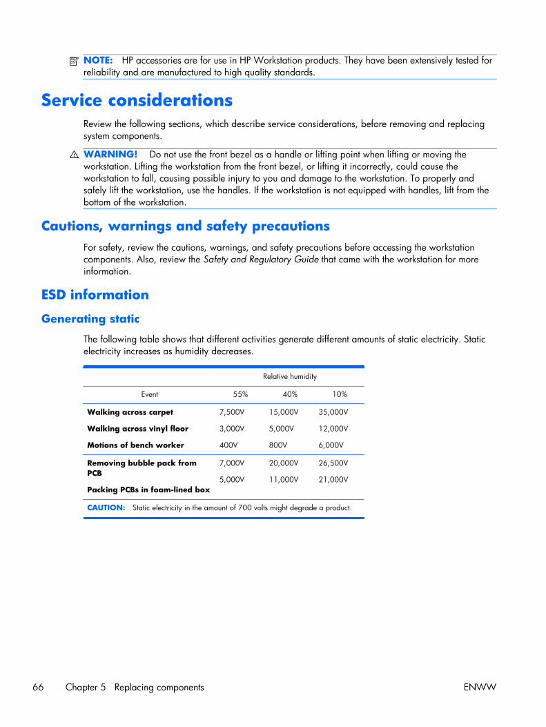
NOTE: HP accessories are for use in HP Workstation products. They have been extensively tested forreliability and are manufactured to high quality standards.
Service considerationsReview the following sections, which describe service considerations, before removing and replacingsystem components.
WARNING! Do not use the front bezel as a handle or lifting point when lifting or moving theworkstation. Lifting the workstation from the front bezel, or lifting it incorrectly, could cause theworkstation to fall, causing possible injury to you and damage to the workstation. To properly andsafely lift the workstation, use the handles. If the workstation is not equipped with handles, lift from thebottom of the workstation.
Cautions, warnings and safety precautionsFor safety, review the cautions, warnings, and safety precautions before accessing the workstationcomponents. Also, review the Safety and Regulatory Guide that came with the workstation for moreinformation.
ESD information
Generating static
The following table shows that different activities generate different amounts of static electricity. Staticelectricity increases as humidity decreases.
Relative humidity
Event 55% 40% 10%
Walking across carpet
Walking across vinyl floor
Motions of bench worker
7,500V
3,000V
400V
15,000V
5,000V
800V
35,000V
12,000V
6,000V
Removing bubble pack fromPCB
Packing PCBs in foam-lined box
7,000V
5,000V
20,000V
11,000V
26,500V
21,000V
CAUTION: Static electricity in the amount of 700 volts might degrade a product.
66 Chapter 5 Replacing components ENWW

Preventing ESD equipment damage
Many electronic components are sensitive to ESD. Circuitry design and structure determine the degreeof sensitivity. The following packaging and grounding precautions are necessary to prevent damage toelectric components and accessories:
● Transport products in static-safe containers such as tubes, bags, or boxes, to avoid hand contact.
● Protect electrostatic parts and assemblies with nonconductive or approved containers orpackaging.
● Keep electrostatic-sensitive parts in their containers until they arrive at static-free stations.
● Place items on a grounded surface before removing them from containers.
● When handling or touching a sensitive component or assembly, ground yourself by touching thechassis.
● Avoid contact with pins, leads, or circuitry.
● Place reusable electrostatic-sensitive parts from assemblies in protective packaging ornonconductive foam.
Personal grounding methods and equipment
Use the following items to help prevent ESD damage:
● Wrist straps—These are flexible straps with a maximum of one megohm ± 10% resistance in theground cords. To provide a proper ground, wear the strap against bare skin. The ground cordmust be connected and fit snugly into the banana plug connector on the grounding mat orworkstation.
● Heel straps, toe straps, and boot straps—These can be used at standing workstations andare compatible with most types of shoes or boots. On conductive floors or dissipative floor mats,use them on both feet with a maximum of one megohm ± 10% resistance between the operatorand ground.
The following table shows protection levels available from static shielding materials.
Table 5-1 Static shieldingprotection levels
Method Voltage
Antistatic plastic
Carbon-loaded plastic
Metallized laminate
1,500V
7,500V
15,000V
This section provides guidelines to prevent ESD damage to equipment.
ENWW Service considerations 67
Grounding the work areaTo prevent static damage in the work area:
● Cover the work surface with approved static-dissipative material. Use a wrist strap connected tothe work surface, and properly grounded tools and equipment.
● Use static-dissipative mats, foot straps, or air ionizers to give added protection.
● Handle electrostatic-sensitive components, parts, and assemblies by the case or PCB laminate.Handle them only in static-free work areas.
● Disconnect power and input signals before inserting and removing connectors or test equipment.
● Use fixtures made of static-safe materials when fixtures must directly contact dissipative surfaces.
● Keep work area free of nonconductive materials, such as plastic assembly aids and Styrofoam.
● Use field service tools (such as cutters, screwdrivers, and vacuums) that are conductive.
Recommended ESD prevention materials and equipmentThe recommended materials and equipment are:
● Antistatic tape
● Antistatic smocks, aprons, and sleeve protectors
● Conductive bins and other assembly or soldering aids
● Conductive foam
● Conductive tabletop workstations with a ground cord of one megohm ± 10% resistance
● Static-dissipative table or floor mats with a hard-tie to ground
● Field service kits
● Static awareness labels
● Wrist straps and footwear straps providing one megohm ± 10% resistance
● Material-handling packages
● Conductive plastic bags
● Conductive plastic tubes
● Conductive tote boxes
● Opaque shielding bags
● Transparent metallized shielding bags
● Transparent shielding tubes
68 Chapter 5 Replacing components ENWW
Tools and software requirementsThe tools necessary for workstation component removal and installation are:
● Torx T-15 driver
● Flat blade and cross-tip screwdrivers
● Diagnostics software
Special handling of componentsThe components included in this section require special handling when servicing the workstation.
WARNING! Do not use the front bezel as a handle or lifting point when lifting or moving theworkstation. Lifting the workstation from the front bezel, or lifting it incorrectly, could cause theworkstation to fall, causing possible injury to you and damage to the workstation. To properly andsafely lift the workstation, lift from the bottom of the workstation.
Cables and connectors
Handle cables with care to avoid damage. Apply only the tension required to seat or unseat cablesduring insertion or removal from the connector. When possible, handle cables by the connector or pull-strap. In all cases, avoid bending or twisting the cables, and be sure that the cables are routed in sucha way that they cannot be caught or snagged by parts being removed or replaced.
When servicing the workstation, be sure that cables are placed in their proper location during thereassembly process. Improper cable placement can damage the workstation.
ENWW Service considerations 69
Hard disk drives
Hard disk drives are fragile, precision components. Avoid subjecting them to physical shock andvibration. The following guidelines apply to all drives, including failed drives, replacement drives, andspares.
● Do not remove hard disk drives from the shipping package for storage. Keep hard disk drives intheir protective packaging until they are mounted in the workstation.
● Avoid dropping hard disk drives from any height.
● If you are inserting or removing a hard disk drive, power off the workstation. Do not remove ahard disk drive while the workstation is powered on or in standby mode.
● Before handling a drive, be sure that you discharge static electricity. While handling a drive,avoid touching the connector. For more information about preventing electrostatic damage, seeESD information on page 66.
To prevent possible ESD damage when the drive is installed, connect the drive power cable beforeconnecting the data cable. This discharges accumulated static electricity through the drive powercable to the workstation chassis.
● When inserting a drive, do not use excessive force.
● Avoid exposing a hard disk drive to liquids, temperature extremes, or products with magneticfields such as monitors or speakers.
Lithium coin cell battery
The battery included with the workstation provides power to the real-time clock and has a lifetime ofabout three years.
For instructions on battery removal and replacement, see Battery on page 128.
WARNING! This workstation contains a lithium battery. There is a risk of fire and chemical burn ifthe battery is handled improperly. Do not disassemble, crush, puncture, short the external contacts,dispose of in water or fire, or expose the battery to temperatures higher than 60° Centigrade (140°Fahrenheit).
NOTE: Do not dispose of batteries, battery packs, and accumulators with general household waste.
70 Chapter 5 Replacing components ENWW

Customer self-repairUnder the Customer Self-Repair program, you can order a replacement part and install the part withoutonsite HP technical assistance. See http://www.hp.com/go/selfrepair/ for information on the programas customer self-repair may be required for some components.
NOTE: Some components, like the liquid cooling system, are not eligible for Customer Self-Repairand must be returned to HP for service. Call HP Support for further instructions before attempting toremove or repair this system.
ENWW Customer self-repair 71
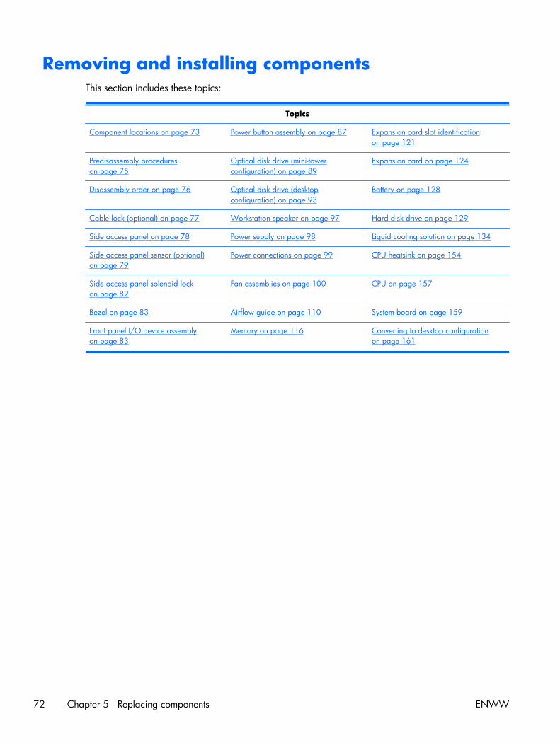
Removing and installing componentsThis section includes these topics:
Topics
Component locations on page 73 Power button assembly on page 87 Expansion card slot identificationon page 121
Predisassembly procedureson page 75
Optical disk drive (mini-towerconfiguration) on page 89
Expansion card on page 124
Disassembly order on page 76 Optical disk drive (desktopconfiguration) on page 93
Battery on page 128
Cable lock (optional) on page 77 Workstation speaker on page 97 Hard disk drive on page 129
Side access panel on page 78 Power supply on page 98 Liquid cooling solution on page 134
Side access panel sensor (optional)on page 79
Power connections on page 99 CPU heatsink on page 154
Side access panel solenoid lockon page 82
Fan assemblies on page 100 CPU on page 157
Bezel on page 83 Airflow guide on page 110 System board on page 159
Front panel I/O device assemblyon page 83
Memory on page 116 Converting to desktop configurationon page 161
72 Chapter 5 Replacing components ENWW
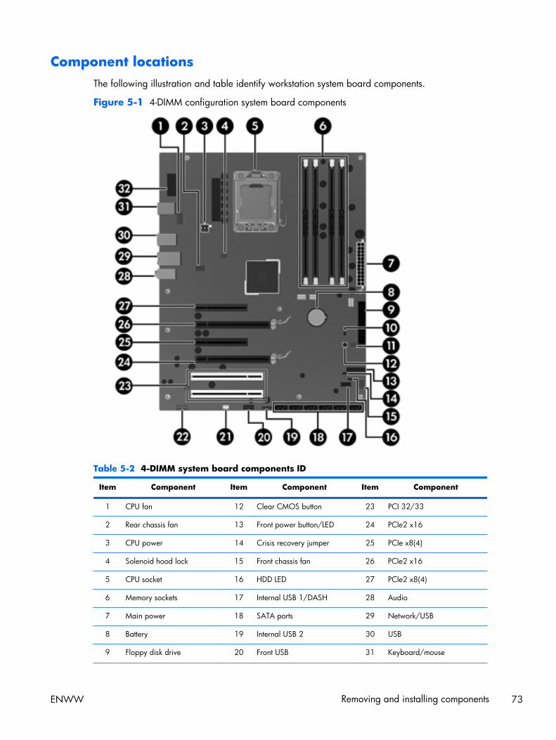
Component locationsThe following illustration and table identify workstation system board components.
Figure 5-1 4-DIMM configuration system board components
Table 5-2 4-DIMM system board components ID
Item Component Item Component Item Component
1 CPU fan 12 Clear CMOS button 23 PCI 32/33
2 Rear chassis fan 13 Front power button/LED 24 PCIe2 x16
3 CPU power 14 Crisis recovery jumper 25 PCIe x8(4)
4 Solenoid hood lock 15 Front chassis fan 26 PCIe2 x16
5 CPU socket 16 HDD LED 27 PCIe2 x8(4)
6 Memory sockets 17 Internal USB 1/DASH 28 Audio
7 Main power 18 SATA ports 29 Network/USB
8 Battery 19 Internal USB 2 30 USB
9 Floppy disk drive 20 Front USB 31 Keyboard/mouse
ENWW Removing and installing components 73

Table 5-2 4-DIMM system board components ID (continued)
Item Component Item Component Item Component
10 Password jumper 21 Speaker 32 Serial
11 Chassis intrusion switch 22 Front audio
Figure 5-2 6-DIMM configuration system board components
Table 5-3 6-DIMM system board components ID
Item Component Item Component Item Component
1 CPU fan 12 Clear CMOS button 23 Front audio
2 Rear chassis fan 13 Front power button/LED 24 PCI 32/33
3 CPU power 14 Crisis recovery jumper 25 PCIe2 x16
4 Solenoid hood lock 15 Front chassis fan 26 PCIe x8(4)
5 CPU socket 16 HDD LED 27 PCIe2 x16
6 Memory sockets 17 Internal USB 1/DASH 28 PCIe2 x8(4)
74 Chapter 5 Replacing components ENWW
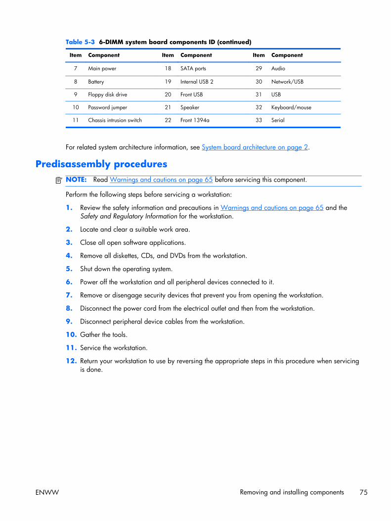
Table 5-3 6-DIMM system board components ID (continued)
Item Component Item Component Item Component
7 Main power 18 SATA ports 29 Audio
8 Battery 19 Internal USB 2 30 Network/USB
9 Floppy disk drive 20 Front USB 31 USB
10 Password jumper 21 Speaker 32 Keyboard/mouse
11 Chassis intrusion switch 22 Front 1394a 33 Serial
For related system architecture information, see System board architecture on page 2.
Predisassembly proceduresNOTE: Read Warnings and cautions on page 65 before servicing this component.
Perform the following steps before servicing a workstation:
1. Review the safety information and precautions in Warnings and cautions on page 65 and theSafety and Regulatory Information for the workstation.
2. Locate and clear a suitable work area.
3. Close all open software applications.
4. Remove all diskettes, CDs, and DVDs from the workstation.
5. Shut down the operating system.
6. Power off the workstation and all peripheral devices connected to it.
7. Remove or disengage security devices that prevent you from opening the workstation.
8. Disconnect the power cord from the electrical outlet and then from the workstation.
9. Disconnect peripheral device cables from the workstation.
10. Gather the tools.
11. Service the workstation.
12. Return your workstation to use by reversing the appropriate steps in this procedure when servicingis done.
ENWW Removing and installing components 75
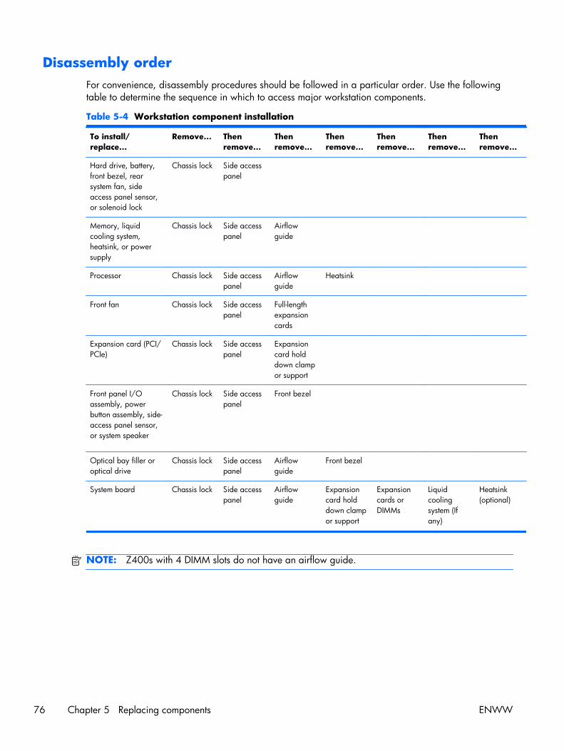
Disassembly orderFor convenience, disassembly procedures should be followed in a particular order. Use the followingtable to determine the sequence in which to access major workstation components.
Table 5-4 Workstation component installation
To install/replace...
Remove... Thenremove...
Thenremove...
Thenremove...
Thenremove...
Thenremove...
Thenremove...
Hard drive, battery,front bezel, rearsystem fan, sideaccess panel sensor,or solenoid lock
Chassis lock Side accesspanel
Memory, liquidcooling system,heatsink, or powersupply
Chassis lock Side accesspanel
Airflowguide
Processor Chassis lock Side accesspanel
Airflowguide
Heatsink
Front fan Chassis lock Side accesspanel
Full-lengthexpansioncards
Expansion card (PCI/PCIe)
Chassis lock Side accesspanel
Expansioncard holddown clampor support
Front panel I/Oassembly, powerbutton assembly, side-access panel sensor,or system speaker
Chassis lock Side accesspanel
Front bezel
Optical bay filler oroptical drive
Chassis lock Side accesspanel
Airflowguide
Front bezel
System board Chassis lock Side accesspanel
Airflowguide
Expansioncard holddown clampor support
Expansioncards orDIMMs
Liquidcoolingsystem (Ifany)
Heatsink(optional)
NOTE: Z400s with 4 DIMM slots do not have an airflow guide.
76 Chapter 5 Replacing components ENWW
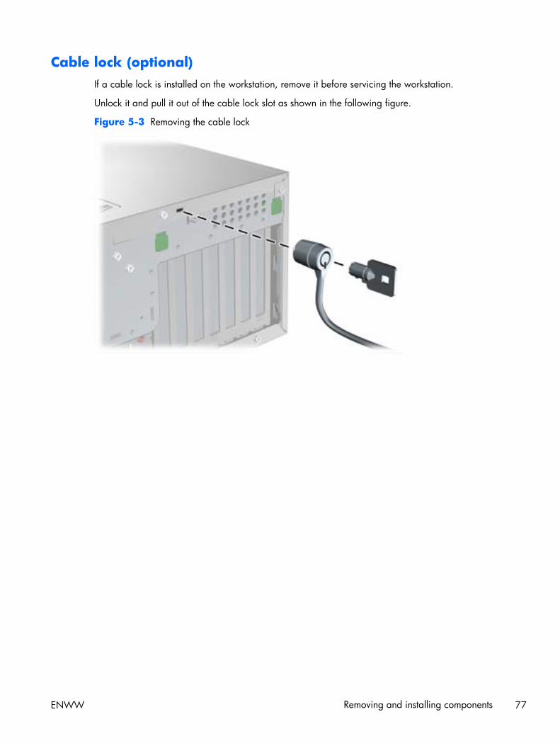
Cable lock (optional)If a cable lock is installed on the workstation, remove it before servicing the workstation.
Unlock it and pull it out of the cable lock slot as shown in the following figure.
Figure 5-3 Removing the cable lock
ENWW Removing and installing components 77

Side access panelBefore accessing the internal components of the workstation, you must remove the side access panel.
This section describes how to remove and install the side access panel.
Removing the side access panel
To remove the side access panel:
WARNING! Before removing the workstation side access panel, be sure that the workstation ispowered off and that the power cord is disconnected from the electrical outlet.
1. Power down the workstation (see Predisassembly procedures on page 75).
2. Disconnect power from the workstation (see Predisassembly procedures on page 75).
3. Remove locks that are present such as a cable lock.
4. Pull up on the handle (1), slide the cover 1/2-inch towards the rear of the system (2), then rotatethe cover off the chassis (3) as shown in the following figure.
Figure 5-4 Removing the side access panel
Installing the side access panel
To install the side access panel:
1. Align the bottom groove of the side panel with the bottom edge of the chassis.
2. Rotate the side panel toward the chassis, slide the panel forward to engage the fingers on the topcover as well as the latch, then press firmly until the latch engages.
78 Chapter 5 Replacing components ENWW
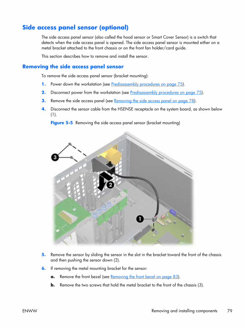
Side access panel sensor (optional)The side access panel sensor (also called the hood sensor or Smart Cover Sensor) is a switch thatdetects when the side access panel is opened. The side access panel sensor is mounted either on ametal bracket attached to the front chassis or on the front fan holder/card guide.
This section describes how to remove and install the sensor.
Removing the side access panel sensor
To remove the side access panel sensor (bracket mounting):
1. Power down the workstation (see Predisassembly procedures on page 75).
2. Disconnect power from the workstation (see Predisassembly procedures on page 75).
3. Remove the side access panel (see Removing the side access panel on page 78).
4. Disconnect the sensor cable from the HSENSE receptacle on the system board, as shown below(1).
Figure 5-5 Removing the side access panel sensor (bracket mounting)
5. Remove the sensor by sliding the sensor in the slot in the bracket toward the front of the chassisand then pushing the sensor down (2).
6. If removing the metal mounting bracket for the sensor:
a. Remove the front bezel (see Removing the front bezel on page 83).
b. Remove the two screws that hold the metal bracket to the front of the chassis (3).
ENWW Removing and installing components 79
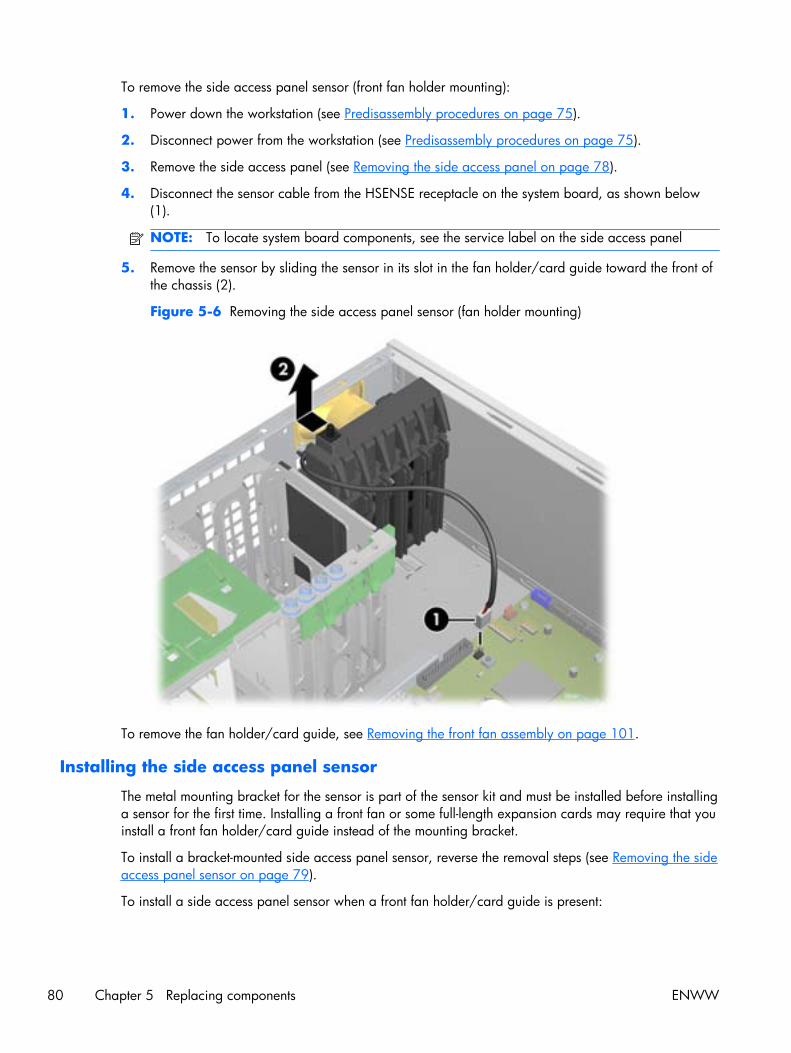
To remove the side access panel sensor (front fan holder mounting):
1. Power down the workstation (see Predisassembly procedures on page 75).
2. Disconnect power from the workstation (see Predisassembly procedures on page 75).
3. Remove the side access panel (see Removing the side access panel on page 78).
4. Disconnect the sensor cable from the HSENSE receptacle on the system board, as shown below(1).
NOTE: To locate system board components, see the service label on the side access panel
5. Remove the sensor by sliding the sensor in its slot in the fan holder/card guide toward the front ofthe chassis (2).
Figure 5-6 Removing the side access panel sensor (fan holder mounting)
To remove the fan holder/card guide, see Removing the front fan assembly on page 101.
Installing the side access panel sensor
The metal mounting bracket for the sensor is part of the sensor kit and must be installed before installinga sensor for the first time. Installing a front fan or some full-length expansion cards may require that youinstall a front fan holder/card guide instead of the mounting bracket.
To install a bracket-mounted side access panel sensor, reverse the removal steps (see Removing the sideaccess panel sensor on page 79).
To install a side access panel sensor when a front fan holder/card guide is present:
80 Chapter 5 Replacing components ENWW
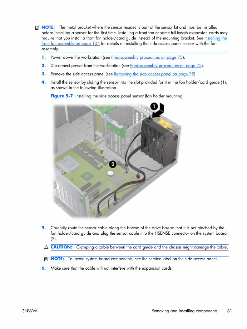
NOTE: The metal bracket where the sensor resides is part of the sensor kit and must be installedbefore installing a sensor for the first time. Installing a front fan or some full-length expansion cards mayrequire that you install a front fan holder/card guide instead of the mounting bracket. See Installing thefront fan assembly on page 104 for details on installing the side access panel sensor with the fanassembly.
1. Power down the workstation (see Predisassembly procedures on page 75).
2. Disconnect power from the workstation (see Predisassembly procedures on page 75).
3. Remove the side access panel (see Removing the side access panel on page 78).
4. Install the sensor by sliding the sensor into the slot provided for it in the fan holder/card guide (1),as shown in the following illustration.
Figure 5-7 Installing the side access panel sensor (fan holder mounting)
5. Carefully route the sensor cable along the bottom of the drive bay so that it is not pinched by thefan holder/card guide and plug the sensor cable into the HSENSE connector on the system board(2).
CAUTION: Clamping a cable between the card guide and the chassis might damage the cable.
NOTE: To locate system board components, see the service label on the side access panel.
6. Make sure that the cable will not interfere with the expansion cards.
ENWW Removing and installing components 81

Side access panel solenoid lockThe side access panel solenoid lock provides a method to lock the side access panel by means of alocal or remote signal-controlled solenoid.
This section describes how to remove and install the side access panel solenoid lock.
Removing the side access panel solenoid lock
To remove the side access panel solenoid lock:
1. Power down the workstation (see Predisassembly procedures on page 75).
2. Disconnect power from the workstation (see Predisassembly procedures on page 75).
3. Remove the side access panel (see Removing the side access panel on page 78).
4. Disconnect the side access panel solenoid lock cable from the system board (1).
5. Remove the two screws that fasten the solenoid lock to the chassis (2), as shown in the followingfigure.
6. Pull the solenoid lock assembly inward and then up (3) to remove the assembly from the chassis.
Figure 5-8 Removing the side access panel solenoid lock
Installing the side access panel solenoid lock
Reverse the above steps to install the side access panel solenoid lock. This involves connecting thesolenoid lock cable to the system board and fastening the solenoid lock to the chassis.
82 Chapter 5 Replacing components ENWW
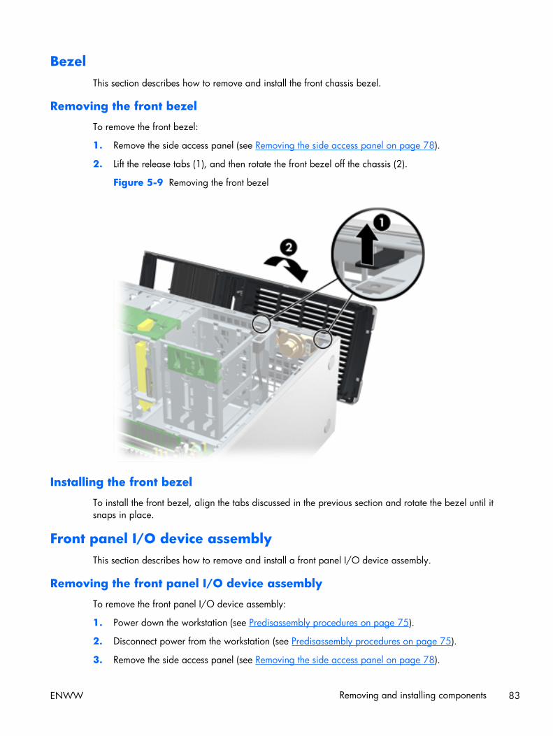
BezelThis section describes how to remove and install the front chassis bezel.
Removing the front bezel
To remove the front bezel:
1. Remove the side access panel (see Removing the side access panel on page 78).
2. Lift the release tabs (1), and then rotate the front bezel off the chassis (2).
Figure 5-9 Removing the front bezel
Installing the front bezel
To install the front bezel, align the tabs discussed in the previous section and rotate the bezel until itsnaps in place.
Front panel I/O device assemblyThis section describes how to remove and install a front panel I/O device assembly.
Removing the front panel I/O device assembly
To remove the front panel I/O device assembly:
1. Power down the workstation (see Predisassembly procedures on page 75).
2. Disconnect power from the workstation (see Predisassembly procedures on page 75).
3. Remove the side access panel (see Removing the side access panel on page 78).
ENWW Removing and installing components 83
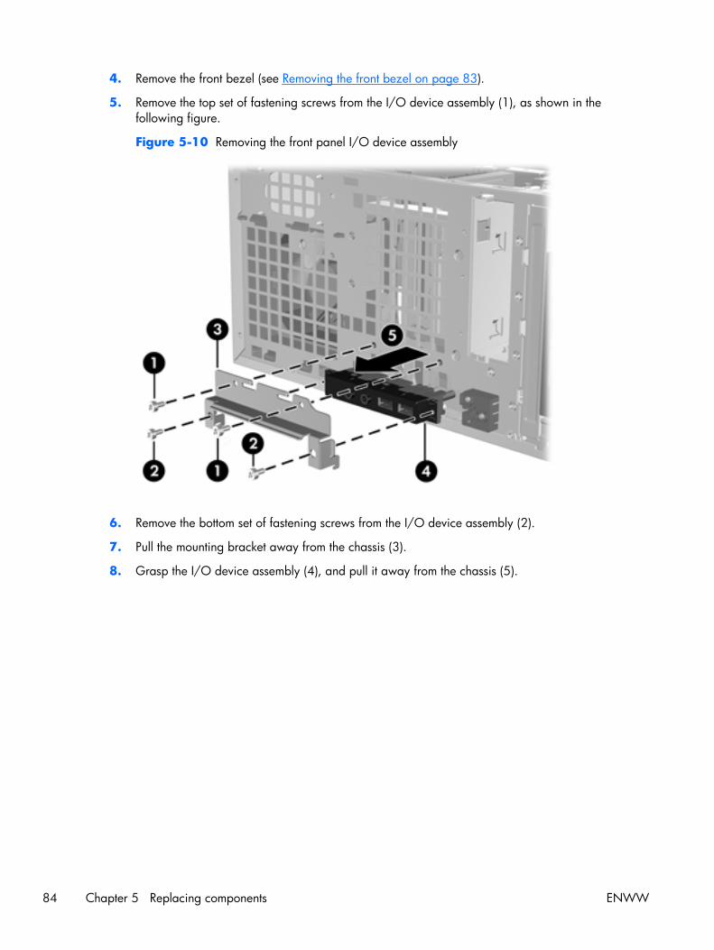
4. Remove the front bezel (see Removing the front bezel on page 83).
5. Remove the top set of fastening screws from the I/O device assembly (1), as shown in thefollowing figure.
Figure 5-10 Removing the front panel I/O device assembly
6. Remove the bottom set of fastening screws from the I/O device assembly (2).
7. Pull the mounting bracket away from the chassis (3).
8. Grasp the I/O device assembly (4), and pull it away from the chassis (5).
84 Chapter 5 Replacing components ENWW

9. Disconnect the front panel I/O device assembly cables from the system board as shown below.
NOTE: Z400s with 6 DIMM slots have an additional cable from the front panel to the 1394aconnector on the system board that you must also disconnect.
Figure 5-11 Disconnecting the front panel I/O cables
10. Carefully guide the front panel I/O device assembly from the chassis.
ENWW Removing and installing components 85
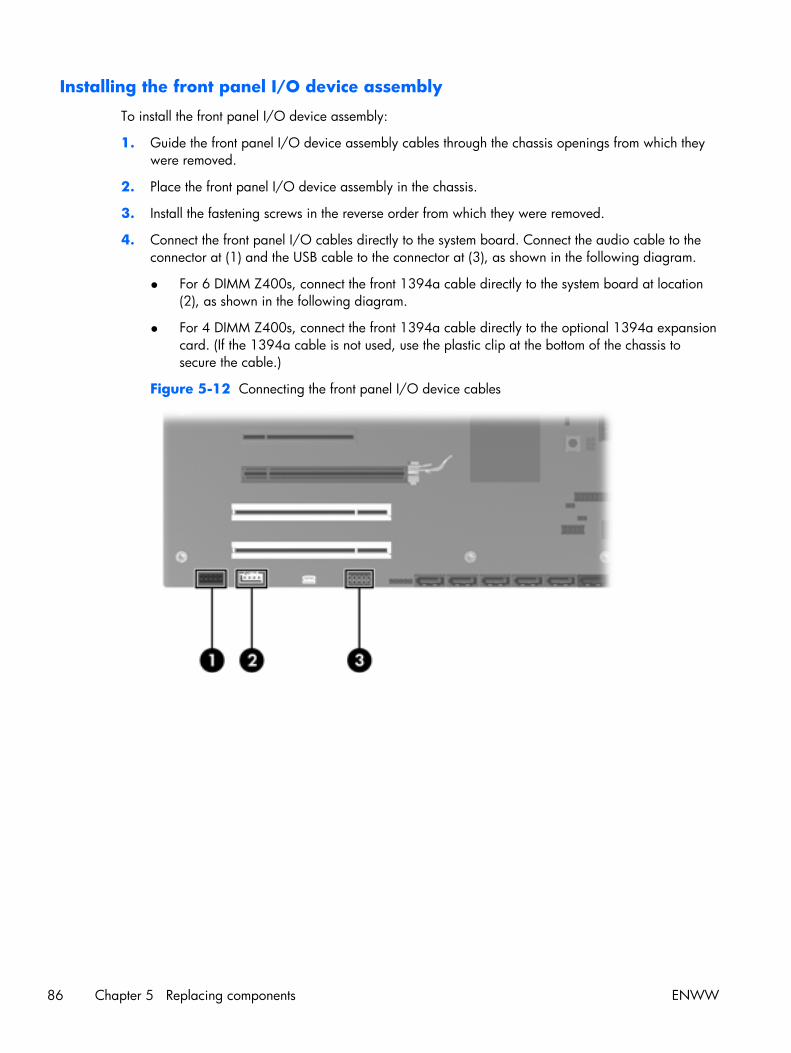
Installing the front panel I/O device assembly
To install the front panel I/O device assembly:
1. Guide the front panel I/O device assembly cables through the chassis openings from which theywere removed.
2. Place the front panel I/O device assembly in the chassis.
3. Install the fastening screws in the reverse order from which they were removed.
4. Connect the front panel I/O cables directly to the system board. Connect the audio cable to theconnector at (1) and the USB cable to the connector at (3), as shown in the following diagram.
● For 6 DIMM Z400s, connect the front 1394a cable directly to the system board at location(2), as shown in the following diagram.
● For 4 DIMM Z400s, connect the front 1394a cable directly to the optional 1394a expansioncard. (If the 1394a cable is not used, use the plastic clip at the bottom of the chassis tosecure the cable.)
Figure 5-12 Connecting the front panel I/O device cables
86 Chapter 5 Replacing components ENWW
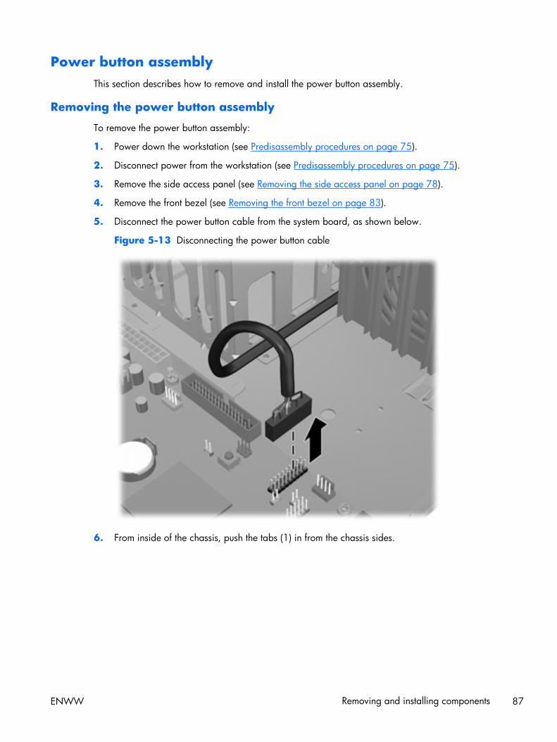
Power button assemblyThis section describes how to remove and install the power button assembly.
Removing the power button assembly
To remove the power button assembly:
1. Power down the workstation (see Predisassembly procedures on page 75).
2. Disconnect power from the workstation (see Predisassembly procedures on page 75).
3. Remove the side access panel (see Removing the side access panel on page 78).
4. Remove the front bezel (see Removing the front bezel on page 83).
5. Disconnect the power button cable from the system board, as shown below.
Figure 5-13 Disconnecting the power button cable
6. From inside of the chassis, push the tabs (1) in from the chassis sides.
ENWW Removing and installing components 87
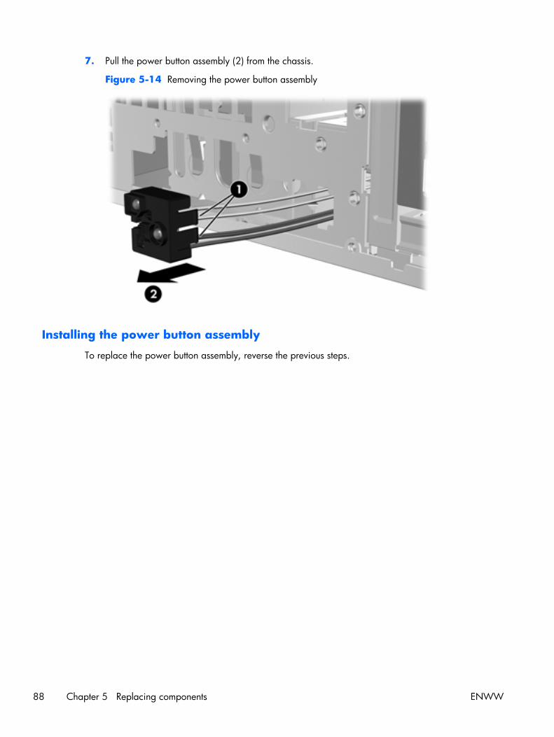
7. Pull the power button assembly (2) from the chassis.
Figure 5-14 Removing the power button assembly
Installing the power button assembly
To replace the power button assembly, reverse the previous steps.
88 Chapter 5 Replacing components ENWW
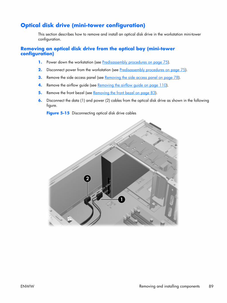
Optical disk drive (mini-tower configuration)This section describes how to remove and install an optical disk drive in the workstation mini-towerconfiguration.
Removing an optical disk drive from the optical bay (mini-towerconfiguration)
1. Power down the workstation (see Predisassembly procedures on page 75).
2. Disconnect power from the workstation (see Predisassembly procedures on page 75).
3. Remove the side access panel (see Removing the side access panel on page 78).
4. Remove the airflow guide (see Removing the airflow guide on page 110).
5. Remove the front bezel (see Removing the front bezel on page 83).
6. Disconnect the data (1) and power (2) cables from the optical disk drive as shown in the followingfigure.
Figure 5-15 Disconnecting optical disk drive cables
ENWW Removing and installing components 89
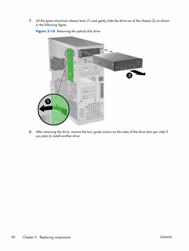
7. Lift the green drive-lock release lever (1) and gently slide the drive out of the chassis (2) as shownin the following figure.
Figure 5-16 Removing the optical disk drive
8. After removing the drive, remove the four guide screws on the sides of the drive (two per side) ifyou plan to install another drive.
90 Chapter 5 Replacing components ENWW
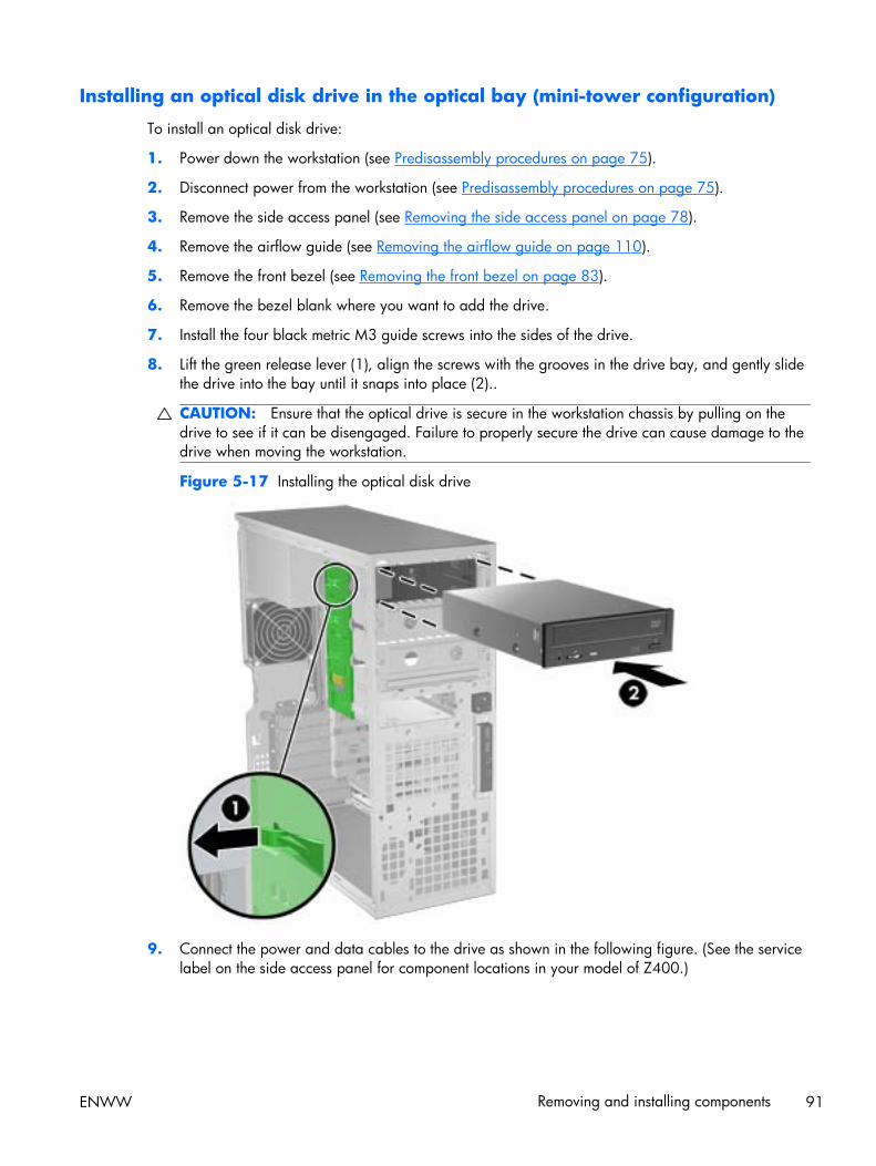
Installing an optical disk drive in the optical bay (mini-tower configuration)
To install an optical disk drive:
1. Power down the workstation (see Predisassembly procedures on page 75).
2. Disconnect power from the workstation (see Predisassembly procedures on page 75).
3. Remove the side access panel (see Removing the side access panel on page 78).
4. Remove the airflow guide (see Removing the airflow guide on page 110).
5. Remove the front bezel (see Removing the front bezel on page 83).
6. Remove the bezel blank where you want to add the drive.
7. Install the four black metric M3 guide screws into the sides of the drive.
8. Lift the green release lever (1), align the screws with the grooves in the drive bay, and gently slidethe drive into the bay until it snaps into place (2)..
CAUTION: Ensure that the optical drive is secure in the workstation chassis by pulling on thedrive to see if it can be disengaged. Failure to properly secure the drive can cause damage to thedrive when moving the workstation.
Figure 5-17 Installing the optical disk drive
9. Connect the power and data cables to the drive as shown in the following figure. (See the servicelabel on the side access panel for component locations in your model of Z400.)
ENWW Removing and installing components 91

10. Connect the optical disk drive data cable to the appropriate SATA port on the system board asshown in the following figure.
Figure 5-18 Connecting power and data cables
11. Reverse steps 1–5 to replace the components you removed during installation.
92 Chapter 5 Replacing components ENWW

Optical disk drive (desktop configuration)This section describes how to remove and install an optical disk drive in the workstation desktopconfiguration.
Removing an optical drive (desktop configuration)
1. Power down the workstation (see Predisassembly procedures on page 75).
2. Disconnect power from the system (Predisassembly procedures on page 75),
3. Remove the side access panel (Removing the side access panel on page 78).
4. If your system has an airflow guide, remove it (see Removing the airflow guide on page 110).
5. Remove the front bezel (Removing the front bezel on page 83).
6. Disconnect the data (1) and power (2) cables from the optical disk drive as shown in the followingfigure. (The connector colors might be different than shown in the figure.)
Figure 5-19 Disconnecting the optical drive cables
ENWW Removing and installing components 93
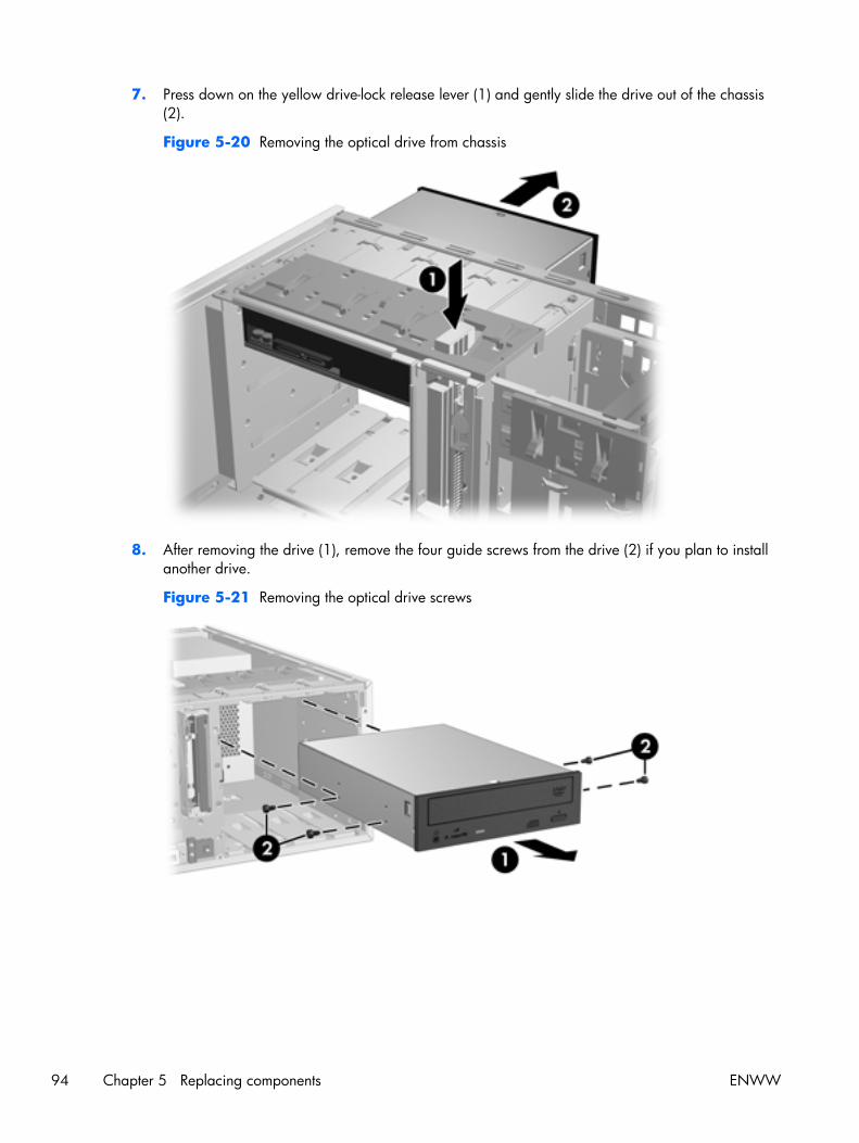
7. Press down on the yellow drive-lock release lever (1) and gently slide the drive out of the chassis(2).
Figure 5-20 Removing the optical drive from chassis
8. After removing the drive (1), remove the four guide screws from the drive (2) if you plan to installanother drive.
Figure 5-21 Removing the optical drive screws
94 Chapter 5 Replacing components ENWW
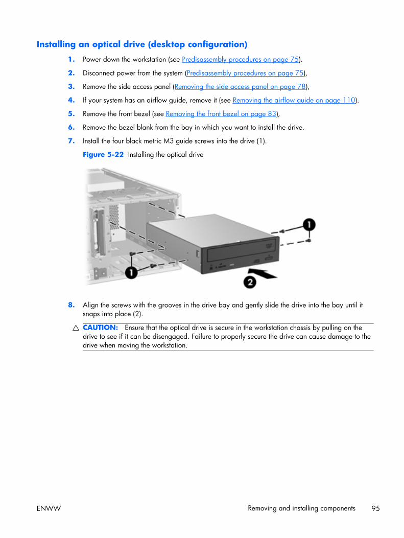
Installing an optical drive (desktop configuration)
1. Power down the workstation (see Predisassembly procedures on page 75).
2. Disconnect power from the system (Predisassembly procedures on page 75),
3. Remove the side access panel (Removing the side access panel on page 78),
4. If your system has an airflow guide, remove it (see Removing the airflow guide on page 110).
5. Remove the front bezel (see Removing the front bezel on page 83),
6. Remove the bezel blank from the bay in which you want to install the drive.
7. Install the four black metric M3 guide screws into the drive (1).
Figure 5-22 Installing the optical drive
8. Align the screws with the grooves in the drive bay and gently slide the drive into the bay until itsnaps into place (2).
CAUTION: Ensure that the optical drive is secure in the workstation chassis by pulling on thedrive to see if it can be disengaged. Failure to properly secure the drive can cause damage to thedrive when moving the workstation.
ENWW Removing and installing components 95
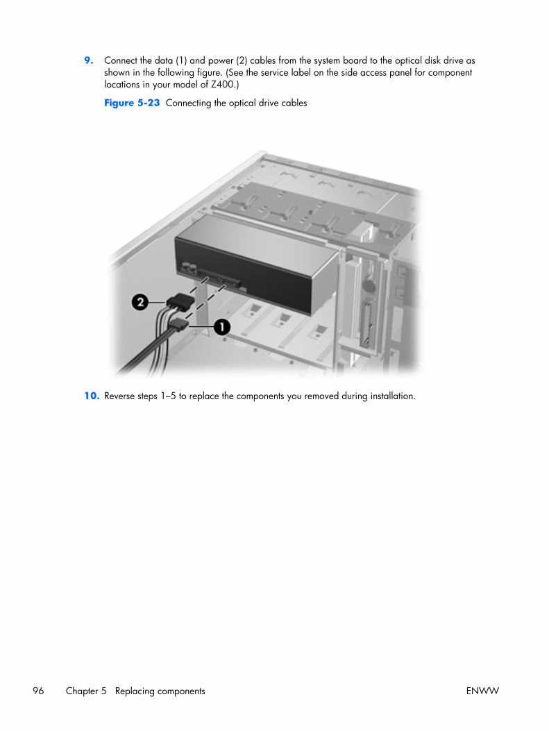
9. Connect the data (1) and power (2) cables from the system board to the optical disk drive asshown in the following figure. (See the service label on the side access panel for componentlocations in your model of Z400.)
Figure 5-23 Connecting the optical drive cables
10. Reverse steps 1–5 to replace the components you removed during installation.
96 Chapter 5 Replacing components ENWW
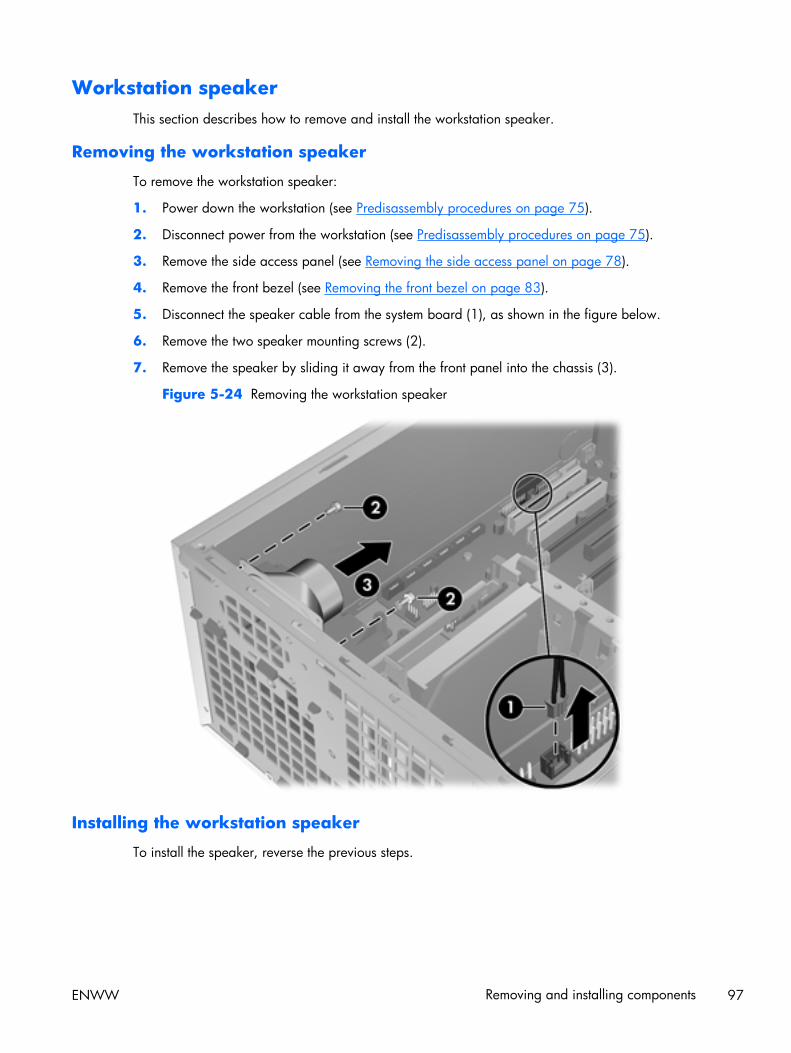
Workstation speakerThis section describes how to remove and install the workstation speaker.
Removing the workstation speaker
To remove the workstation speaker:
1. Power down the workstation (see Predisassembly procedures on page 75).
2. Disconnect power from the workstation (see Predisassembly procedures on page 75).
3. Remove the side access panel (see Removing the side access panel on page 78).
4. Remove the front bezel (see Removing the front bezel on page 83).
5. Disconnect the speaker cable from the system board (1), as shown in the figure below.
6. Remove the two speaker mounting screws (2).
7. Remove the speaker by sliding it away from the front panel into the chassis (3).
Figure 5-24 Removing the workstation speaker
Installing the workstation speaker
To install the speaker, reverse the previous steps.
ENWW Removing and installing components 97
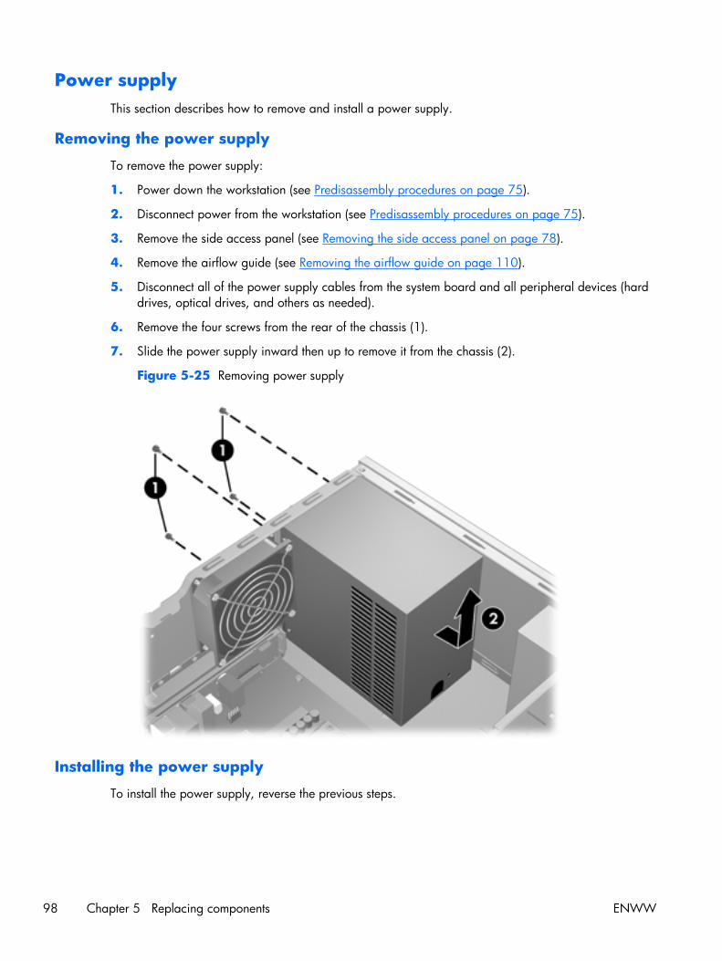
Power supplyThis section describes how to remove and install a power supply.
Removing the power supply
To remove the power supply:
1. Power down the workstation (see Predisassembly procedures on page 75).
2. Disconnect power from the workstation (see Predisassembly procedures on page 75).
3. Remove the side access panel (see Removing the side access panel on page 78).
4. Remove the airflow guide (see Removing the airflow guide on page 110).
5. Disconnect all of the power supply cables from the system board and all peripheral devices (harddrives, optical drives, and others as needed).
6. Remove the four screws from the rear of the chassis (1).
7. Slide the power supply inward then up to remove it from the chassis (2).
Figure 5-25 Removing power supply
Installing the power supply
To install the power supply, reverse the previous steps.
98 Chapter 5 Replacing components ENWW
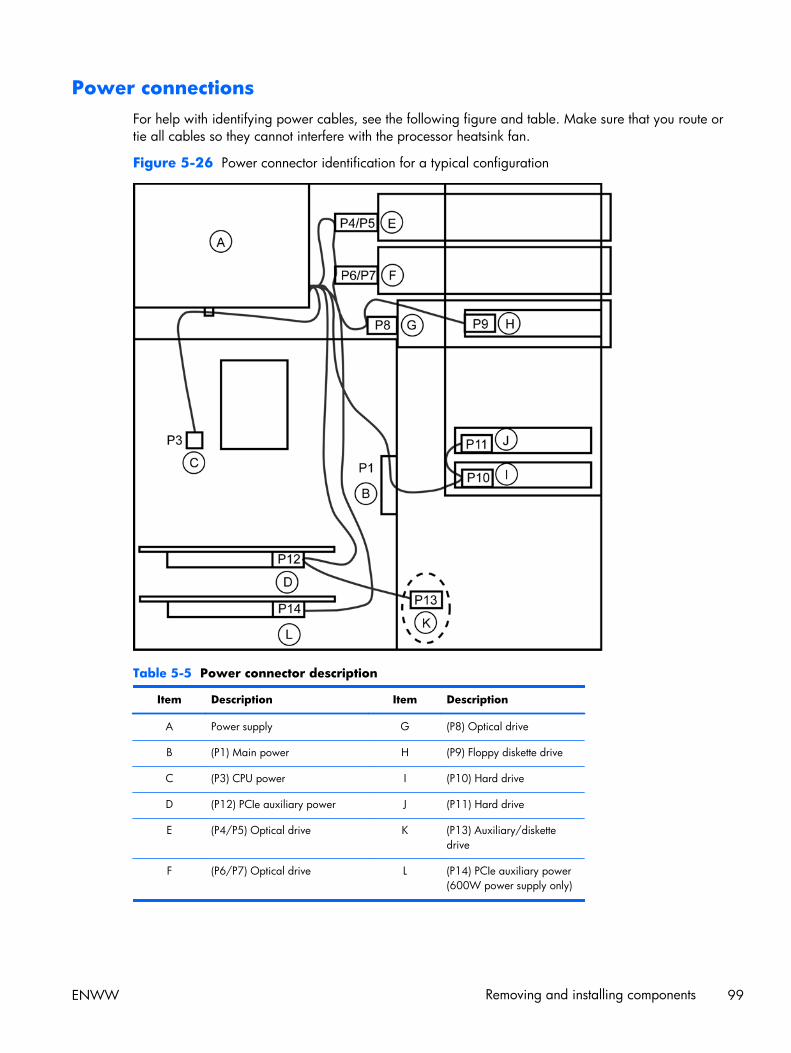
Power connectionsFor help with identifying power cables, see the following figure and table. Make sure that you route ortie all cables so they cannot interfere with the processor heatsink fan.
Figure 5-26 Power connector identification for a typical configuration
Table 5-5 Power connector description
Item Description Item Description
A Power supply G (P8) Optical drive
B (P1) Main power H (P9) Floppy diskette drive
C (P3) CPU power I (P10) Hard drive
D (P12) PCIe auxiliary power J (P11) Hard drive
E (P4/P5) Optical drive K (P13) Auxiliary/diskettedrive
F (P6/P7) Optical drive L (P14) PCIe auxiliary power(600W power supply only)
ENWW Removing and installing components 99
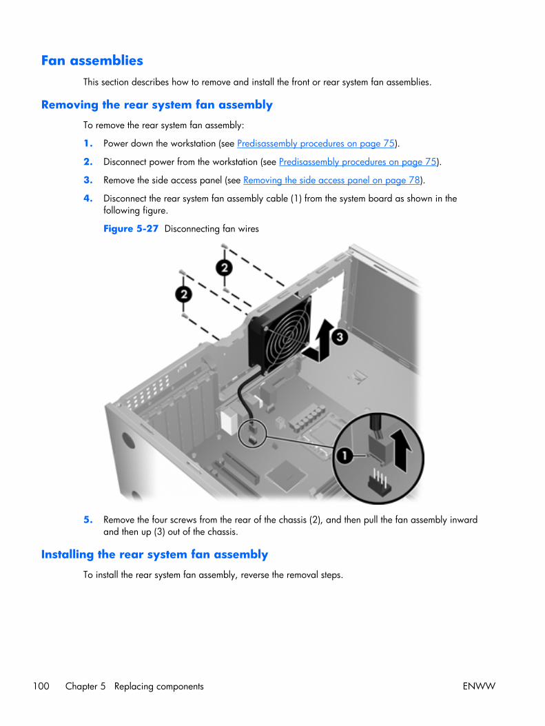
Fan assembliesThis section describes how to remove and install the front or rear system fan assemblies.
Removing the rear system fan assembly
To remove the rear system fan assembly:
1. Power down the workstation (see Predisassembly procedures on page 75).
2. Disconnect power from the workstation (see Predisassembly procedures on page 75).
3. Remove the side access panel (see Removing the side access panel on page 78).
4. Disconnect the rear system fan assembly cable (1) from the system board as shown in thefollowing figure.
Figure 5-27 Disconnecting fan wires
5. Remove the four screws from the rear of the chassis (2), and then pull the fan assembly inwardand then up (3) out of the chassis.
Installing the rear system fan assembly
To install the rear system fan assembly, reverse the removal steps.
100 Chapter 5 Replacing components ENWW
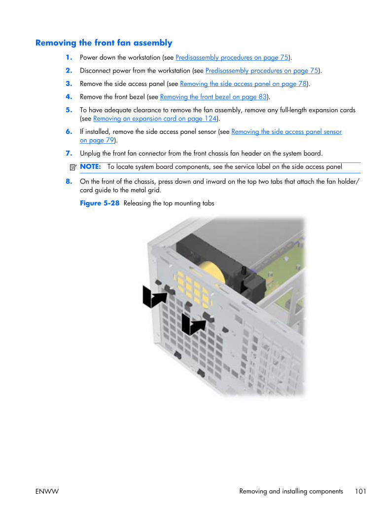
Removing the front fan assembly
1. Power down the workstation (see Predisassembly procedures on page 75).
2. Disconnect power from the workstation (see Predisassembly procedures on page 75).
3. Remove the side access panel (see Removing the side access panel on page 78).
4. Remove the front bezel (see Removing the front bezel on page 83).
5. To have adequate clearance to remove the fan assembly, remove any full-length expansion cards(see Removing an expansion card on page 124).
6. If installed, remove the side access panel sensor (see Removing the side access panel sensoron page 79).
7. Unplug the front fan connector from the front chassis fan header on the system board.
NOTE: To locate system board components, see the service label on the side access panel
8. On the front of the chassis, press down and inward on the top two tabs that attach the fan holder/card guide to the metal grid.
Figure 5-28 Releasing the top mounting tabs
ENWW Removing and installing components 101

9. When the top tabs release, rotate the top of the fan holder/card guide into the chassis (1) so thatthe bottom tabs release from the metal grid on the chassis, and then slide the guide away from thefront panel (2).
Figure 5-29 Freeing the fan assembly from the chassis
102 Chapter 5 Replacing components ENWW

10. Rotate the fan holder/card guide assembly slightly to one side (1), and then lift it up and out of thechassis (2).
Figure 5-30 Removing the fan holder/card guide assembly
ENWW Removing and installing components 103
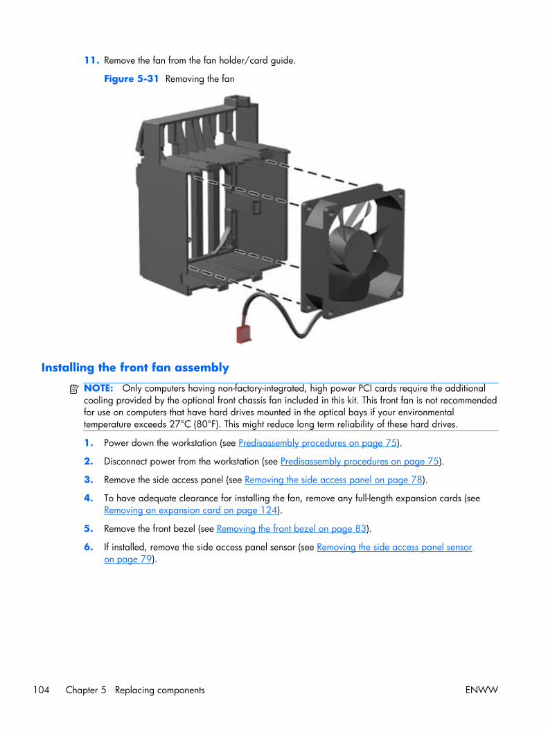
11. Remove the fan from the fan holder/card guide.
Figure 5-31 Removing the fan
Installing the front fan assembly
NOTE: Only computers having non-factory-integrated, high power PCI cards require the additionalcooling provided by the optional front chassis fan included in this kit. This front fan is not recommendedfor use on computers that have hard drives mounted in the optical bays if your environmentaltemperature exceeds 27°C (80°F). This might reduce long term reliability of these hard drives.
1. Power down the workstation (see Predisassembly procedures on page 75).
2. Disconnect power from the workstation (see Predisassembly procedures on page 75).
3. Remove the side access panel (see Removing the side access panel on page 78).
4. To have adequate clearance for installing the fan, remove any full-length expansion cards (seeRemoving an expansion card on page 124).
5. Remove the front bezel (see Removing the front bezel on page 83).
6. If installed, remove the side access panel sensor (see Removing the side access panel sensoron page 79).
104 Chapter 5 Replacing components ENWW
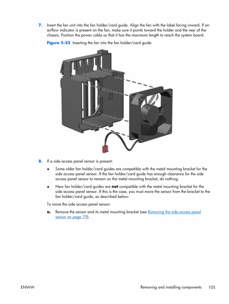
7. Insert the fan unit into the fan holder/card guide. Align the fan with the label facing inward. If anairflow indicator is present on the fan, make sure it points toward the holder and the rear of thechassis. Position the power cable so that it has the maximum length to reach the system board.
Figure 5-32 Inserting the fan into the fan holder/card guide
8. If a side access panel sensor is present:
● Some older fan holder/card guides are compatible with the metal mounting bracket for theside access panel sensor. If the fan holder/card guide has enough clearance for the sideaccess panel sensor to remain on the metal mounting bracket, do nothing.
● New fan holder/card guides are not compatible with the metal mounting bracket for theside access panel sensor. If this is the case, you must move the sensor from the bracket to thefan holder/card guide, as described below:
To move the side access panel sensor:
a. Remove the sensor and its metal mounting bracket (see Removing the side access panelsensor on page 79).
ENWW Removing and installing components 105

b. Insert the side access panel sensor into the slot provided on the fan holder/card guide.
Figure 5-33 Inserting the side access panel sensor into the fan holder/card guide
106 Chapter 5 Replacing components ENWW
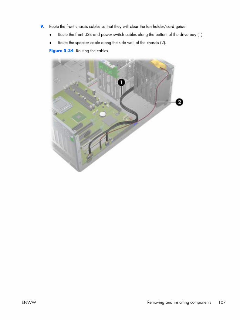
9. Route the front chassis cables so that they will clear the fan holder/card guide:
● Route the front USB and power switch cables along the bottom of the drive bay (1).
● Route the speaker cable along the side wall of the chassis (2).
Figure 5-34 Routing the cables
ENWW Removing and installing components 107
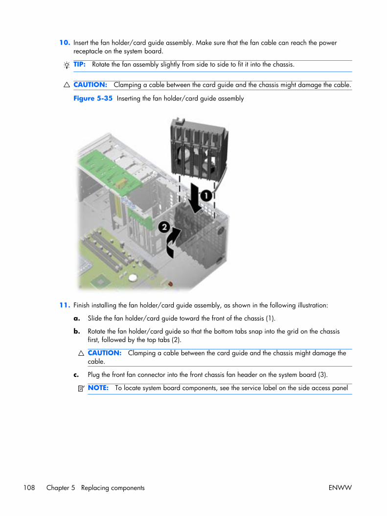
10. Insert the fan holder/card guide assembly. Make sure that the fan cable can reach the powerreceptacle on the system board.
TIP: Rotate the fan assembly slightly from side to side to fit it into the chassis.
CAUTION: Clamping a cable between the card guide and the chassis might damage the cable.
Figure 5-35 Inserting the fan holder/card guide assembly
11. Finish installing the fan holder/card guide assembly, as shown in the following illustration:
a. Slide the fan holder/card guide toward the front of the chassis (1).
b. Rotate the fan holder/card guide so that the bottom tabs snap into the grid on the chassisfirst, followed by the top tabs (2).
CAUTION: Clamping a cable between the card guide and the chassis might damage thecable.
c. Plug the front fan connector into the front chassis fan header on the system board (3).
NOTE: To locate system board components, see the service label on the side access panel
108 Chapter 5 Replacing components ENWW
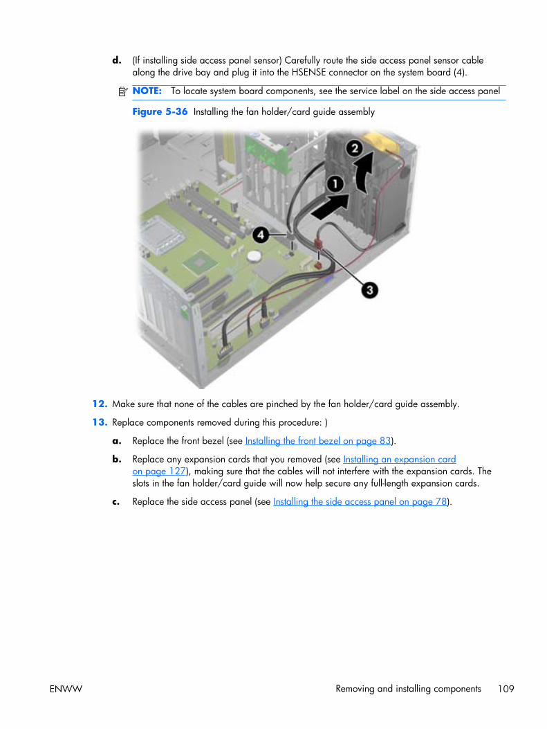
d. (If installing side access panel sensor) Carefully route the side access panel sensor cablealong the drive bay and plug it into the HSENSE connector on the system board (4).
NOTE: To locate system board components, see the service label on the side access panel
Figure 5-36 Installing the fan holder/card guide assembly
12. Make sure that none of the cables are pinched by the fan holder/card guide assembly.
13. Replace components removed during this procedure: )
a. Replace the front bezel (see Installing the front bezel on page 83).
b. Replace any expansion cards that you removed (see Installing an expansion cardon page 127), making sure that the cables will not interfere with the expansion cards. Theslots in the fan holder/card guide will now help secure any full-length expansion cards.
c. Replace the side access panel (see Installing the side access panel on page 78).
ENWW Removing and installing components 109
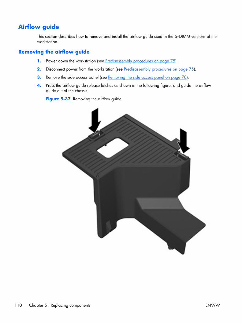
Airflow guideThis section describes how to remove and install the airflow guide used in the 6–DIMM versions of theworkstation.
Removing the airflow guide
1. Power down the workstation (see Predisassembly procedures on page 75).
2. Disconnect power from the workstation (see Predisassembly procedures on page 75).
3. Remove the side access panel (see Removing the side access panel on page 78).
4. Press the airflow guide release latches as shown in the following figure, and guide the airflowguide out of the chassis.
Figure 5-37 Removing the airflow guide
110 Chapter 5 Replacing components ENWW
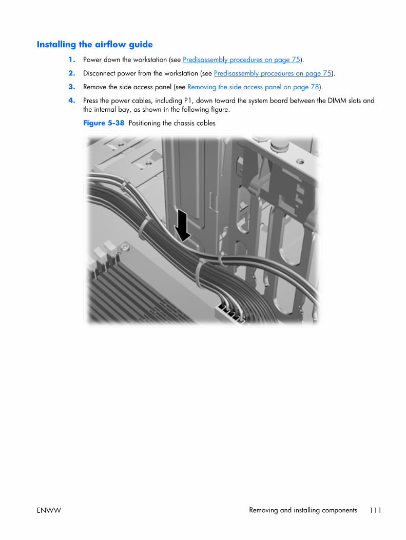
Installing the airflow guide
1. Power down the workstation (see Predisassembly procedures on page 75).
2. Disconnect power from the workstation (see Predisassembly procedures on page 75).
3. Remove the side access panel (see Removing the side access panel on page 78).
4. Press the power cables, including P1, down toward the system board between the DIMM slots andthe internal bay, as shown in the following figure.
Figure 5-38 Positioning the chassis cables
ENWW Removing and installing components 111
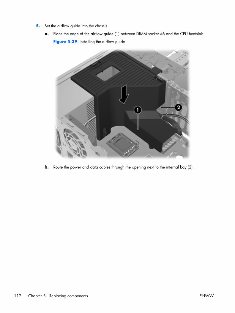
5. Set the airflow guide into the chassis.
a. Place the edge of the airflow guide (1) between DIMM socket #6 and the CPU heatsink.
Figure 5-39 Installing the airflow guide
b. Route the power and data cables through the opening next to the internal bay (2).
112 Chapter 5 Replacing components ENWW
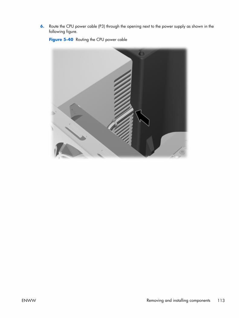
6. Route the CPU power cable (P3) through the opening next to the power supply as shown in thefollowing figure.
Figure 5-40 Routing the CPU power cable
ENWW Removing and installing components 113
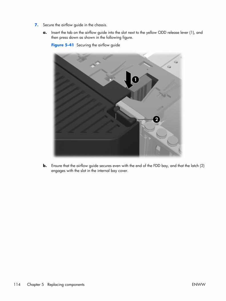
7. Secure the airflow guide in the chassis.
a. Insert the tab on the airflow guide into the slot next to the yellow ODD release lever (1), andthen press down as shown in the following figure.
Figure 5-41 Securing the airflow guide
b. Ensure that the airflow guide secures even with the end of the FDD bay, and that the latch (2)engages with the slot in the internal bay cover.
114 Chapter 5 Replacing components ENWW
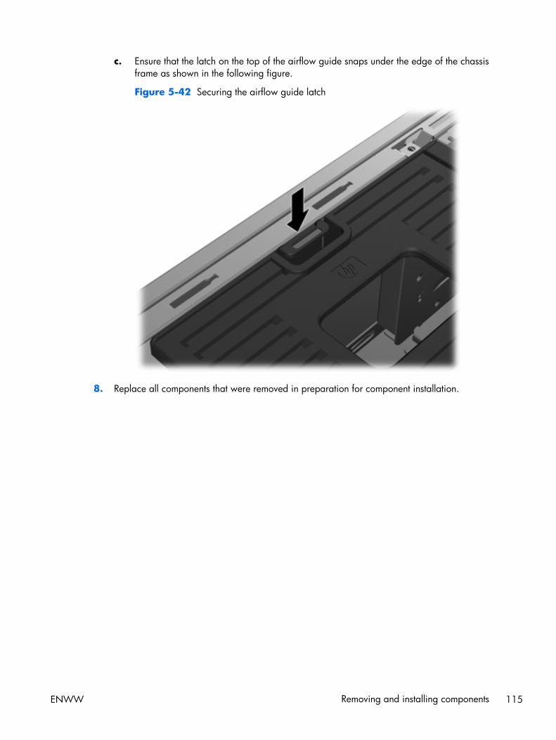
c. Ensure that the latch on the top of the airflow guide snaps under the edge of the chassisframe as shown in the following figure.
Figure 5-42 Securing the airflow guide latch
8. Replace all components that were removed in preparation for component installation.
ENWW Removing and installing components 115
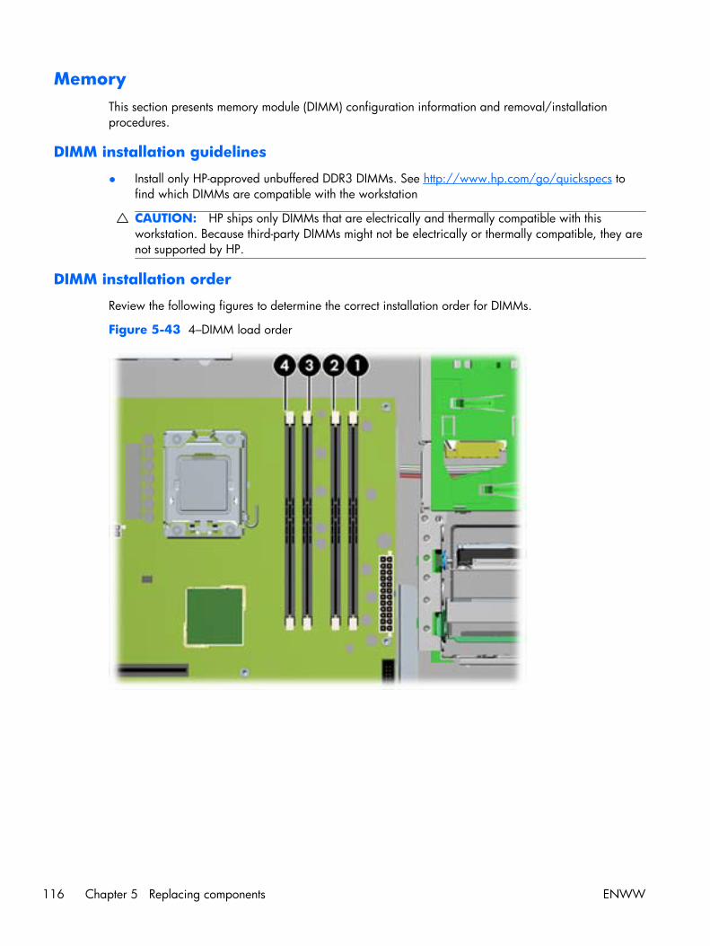
MemoryThis section presents memory module (DIMM) configuration information and removal/installationprocedures.
DIMM installation guidelines
● Install only HP-approved unbuffered DDR3 DIMMs. See http://www.hp.com/go/quickspecs tofind which DIMMs are compatible with the workstation
CAUTION: HP ships only DIMMs that are electrically and thermally compatible with thisworkstation. Because third-party DIMMs might not be electrically or thermally compatible, they arenot supported by HP.
DIMM installation order
Review the following figures to determine the correct installation order for DIMMs.
Figure 5-43 4–DIMM load order
116 Chapter 5 Replacing components ENWW

Figure 5-44 6–DIMM load order
Supported DIMM configurations
The workstation supports these DIMM arrangements, depending on which Z400 product you order:
● Up to six DIMM slots
● Memory range from 1 GB to 16GB for the 4-DIMM product
● Memory range from 1 GB to 24GB for the 6-DIMM product
● No support for mirroring
● No support for DIMM sparing
BIOS errors and warnings
The BIOS generates warnings/errors on invalid memory configurations:
● If the BIOS can find a valid memory configuration by disabling plugged-in memory, it does so andreports a warning during POST. the workstation can still be started. The warning will indicate thelocation of the failed DIMM on the system board.
● If there is no way for the BIOS to obtain a valid memory configuration by disabling plugged-inmemory, the BIOS halts with a diagnostics 2006 code for memory error (five beeps and blinks).
ENWW Removing and installing components 117
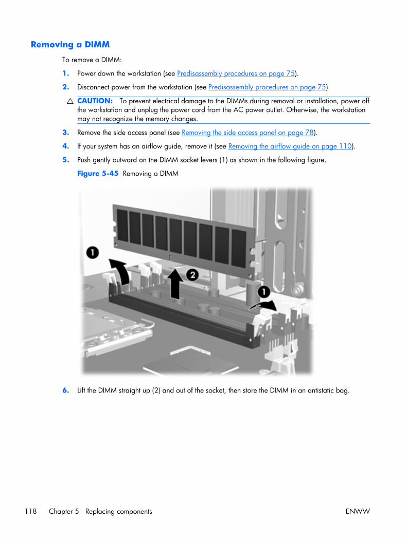
Removing a DIMM
To remove a DIMM:
1. Power down the workstation (see Predisassembly procedures on page 75).
2. Disconnect power from the workstation (see Predisassembly procedures on page 75).
CAUTION: To prevent electrical damage to the DIMMs during removal or installation, power offthe workstation and unplug the power cord from the AC power outlet. Otherwise, the workstationmay not recognize the memory changes.
3. Remove the side access panel (see Removing the side access panel on page 78).
4. If your system has an airflow guide, remove it (see Removing the airflow guide on page 110).
5. Push gently outward on the DIMM socket levers (1) as shown in the following figure.
Figure 5-45 Removing a DIMM
6. Lift the DIMM straight up (2) and out of the socket, then store the DIMM in an antistatic bag.
118 Chapter 5 Replacing components ENWW
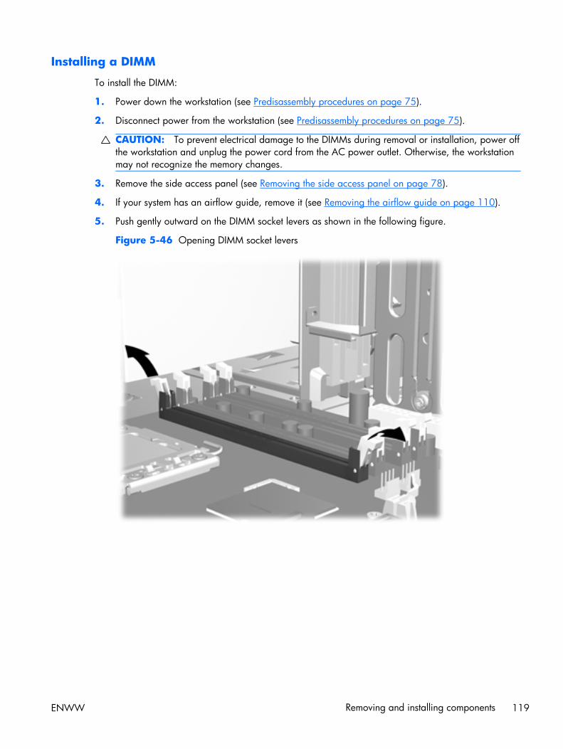
Installing a DIMM
To install the DIMM:
1. Power down the workstation (see Predisassembly procedures on page 75).
2. Disconnect power from the workstation (see Predisassembly procedures on page 75).
CAUTION: To prevent electrical damage to the DIMMs during removal or installation, power offthe workstation and unplug the power cord from the AC power outlet. Otherwise, the workstationmay not recognize the memory changes.
3. Remove the side access panel (see Removing the side access panel on page 78).
4. If your system has an airflow guide, remove it (see Removing the airflow guide on page 110).
5. Push gently outward on the DIMM socket levers as shown in the following figure.
Figure 5-46 Opening DIMM socket levers
ENWW Removing and installing components 119
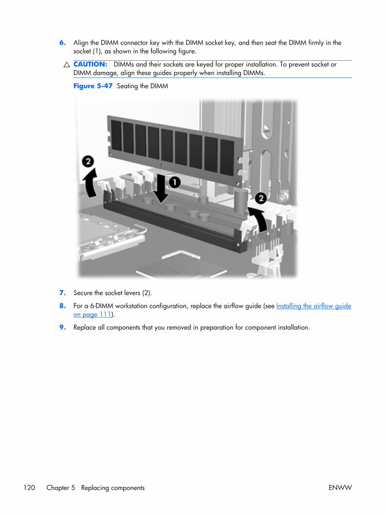
6. Align the DIMM connector key with the DIMM socket key, and then seat the DIMM firmly in thesocket (1), as shown in the following figure.
CAUTION: DIMMs and their sockets are keyed for proper installation. To prevent socket orDIMM damage, align these guides properly when installing DIMMs.
Figure 5-47 Seating the DIMM
7. Secure the socket levers (2).
8. For a 6-DIMM workstation configuration, replace the airflow guide (see Installing the airflow guideon page 111).
9. Replace all components that you removed in preparation for component installation.
120 Chapter 5 Replacing components ENWW
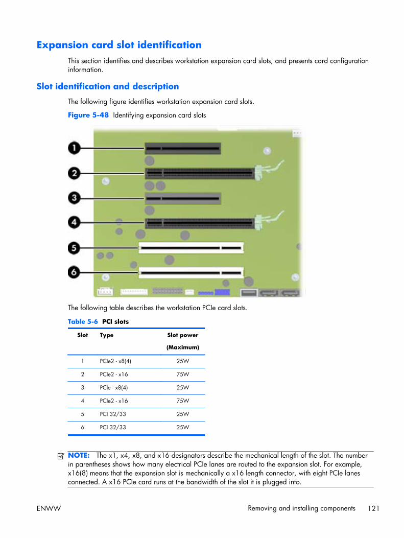
Expansion card slot identificationThis section identifies and describes workstation expansion card slots, and presents card configurationinformation.
Slot identification and description
The following figure identifies workstation expansion card slots.
Figure 5-48 Identifying expansion card slots
The following table describes the workstation PCIe card slots.
Table 5-6 PCI slots
Slot Type Slot power
(Maximum)
1 PCIe2 - x8(4) 25W
2 PCIe2 - x16 75W
3 PCIe - x8(4) 25W
4 PCIe2 - x16 75W
5 PCI 32/33 25W
6 PCI 32/33 25W
NOTE: The x1, x4, x8, and x16 designators describe the mechanical length of the slot. The numberin parentheses shows how many electrical PCIe lanes are routed to the expansion slot. For example,x16(8) means that the expansion slot is mechanically a x16 length connector, with eight PCIe lanesconnected. A x16 PCIe card runs at the bandwidth of the slot it is plugged into.
ENWW Removing and installing components 121
Slots one and three use open-ended PCIe connectors, so a PCIe x16 card can be inserted. Graphicscards greater than 75 watts require the use of an auxiliary power cable adapter.
Card configuration restrictions for power supplies
CAUTION: To prevent damage, the overall power consumption of the workstation (including I/Ocards, CPU, and memory) must not exceed the maximum rating of the workstation power supply. Forpower supply information, see Power supply specifications on page 10.
The maximum graphics configurations are:
● 475W power supply
◦ A graphics card up to 150W in the primary graphics slot
◦ A second graphics card in the second PCIe2 x16 slot (slot 4), provided the combined powerconsumption of both cards does not exceed 150W
● 600W power supply
◦ A graphics card up to 250W in the primary graphics slot
◦ A second graphics card in the second PCIe2 x16 slot (slot 4), provided the combined powerconsumption of both cards does not exceed 250W
If you use a graphics card with greater than 75 watts of power, leave the adjacent slot empty. Themaximum graphics power depends on CPU and memory selections. Follow any additional workstationconfiguration restrictions.
122 Chapter 5 Replacing components ENWW
Choosing an expansion card slot
Whenever possible, use the following tips to help you select the proper slot for an expansion card:
● Insert the primary graphics card in a PCIe x16 slot intended for graphics.
● Insert a second graphics card in a second PCIe x16 slot intended for a secondary graphics card.
● Install full-length cards in slots that support full-length cards.
● For optimal cooling and acoustics do not insert a card next to a graphics card to avoid blockingthe graphics card heatsink and fan. This is especially important for a card that requires anauxiliary power cable. For best results, choose a lower profile card to place next to the heatsinkand fan.
● Install a card in a slot that most closely matches its interface technology:
◦ Install a PCIe Gen2 x8 card in a PCIe Gen2 x8 slot.
◦ Install a PCIe Gen1 x8 card in a PCIe Gen1 x8 slot.
◦ Install a PCIe Gen1 x4 card in a PCIe Gen1 x4 slot.
◦ Install a PCIe Gen1 x1 card in a PCIe Gen1 x1 slot.
◦ Install a PCI card in a PCI slot.
◦ Whenever possible, install a PCIe x1 card in a x1 slot.
● Leave as much space as possible between cards.
● For best operational efficiency, select a slot that:
◦ Electrically matches the number of PCIe card lanes (e.g., x4 in a x4 slot).
◦ Has more lanes electrically.
◦ Has fewer lanes, but is closer to your needs. For example, place a x16 card in a x8 slot, anda x8 card in a a x4 slot.
● A x1 connector supports a x1 card only. Although, a x1 card can be inserted into any slot, thismay waste the potential for future card placement.
● Install cards that require internal cable connections so that the cables are organized and have theleast amount of strain on them. Some cables may be routed under, rather than over the otherexpansion cards.
● To prevent electromagnetic interference, avoid installing a card with external cable connectionsnext to a graphics card.
ENWW Removing and installing components 123
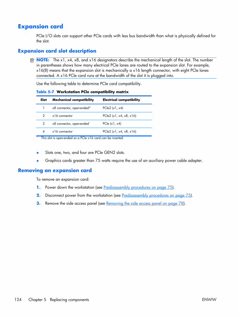
Expansion cardPCIe I/O slots can support other PCIe cards with less bus bandwidth than what is physically defined forthe slot.
Expansion card slot description
NOTE: The x1, x4, x8, and x16 designators describe the mechanical length of the slot. The numberin parentheses shows how many electrical PCIe lanes are routed to the expansion slot. For example,x16(8) means that the expansion slot is mechanically a x16 length connector, with eight PCIe lanesconnected. A x16 PCIe card runs at the bandwidth of the slot it is plugged into.
Use the following table to determine PCIe card compatibility.
Table 5-7 Workstation PCIe compatibility matrix
Slot Mechanical compatibility Electrical compatibility
1 x8 connector, open-ended* PCIe2 (x1, x4)
2 x16 connector PCIe2 (x1, x4, x8, x16)
3 x8 connector, open-ended* PCIe (x1, x4)
4 x16 connector PCIe2 (x1, x4, x8, x16)
* This slot is open-ended so a PCIe x16 card can be inserted.
● Slots one, two, and four are PCIe GEN2 slots.
● Graphics cards greater than 75 watts require the use of an auxiliary power cable adapter.
Removing an expansion card
To remove an expansion card:
1. Power down the workstation (see Predisassembly procedures on page 75).
2. Disconnect power from the workstation (see Predisassembly procedures on page 75).
3. Remove the side access panel (see Removing the side access panel on page 78).
124 Chapter 5 Replacing components ENWW
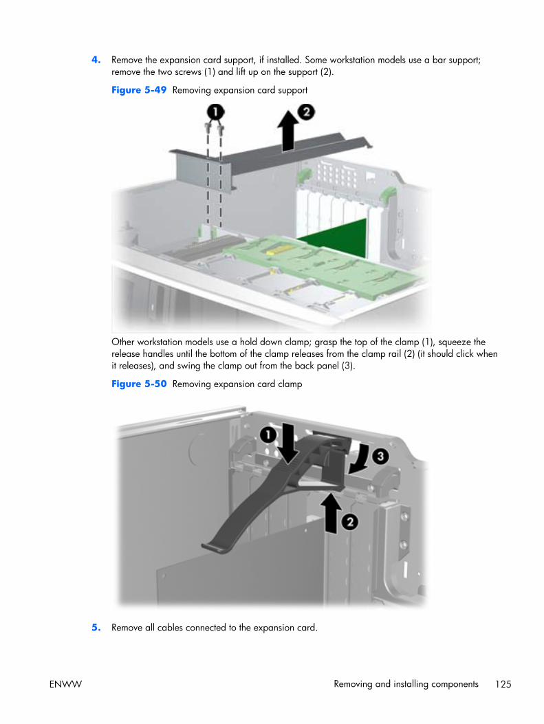
4. Remove the expansion card support, if installed. Some workstation models use a bar support;remove the two screws (1) and lift up on the support (2).
Figure 5-49 Removing expansion card support
Other workstation models use a hold down clamp; grasp the top of the clamp (1), squeeze therelease handles until the bottom of the clamp releases from the clamp rail (2) (it should click whenit releases), and swing the clamp out from the back panel (3).
Figure 5-50 Removing expansion card clamp
5. Remove all cables connected to the expansion card.
ENWW Removing and installing components 125

6. Push down on the expansion card retention clamp levers on the inside of the chassis to open theretention clamp (1) as shown below.
Figure 5-51 Removing the expansion card
Release the expansion card slot latch (2), and then carefully lift the card from the chassis (3).
7. Install an expansion slot cover and close the expansion card retention clamp.
If the expansion card retention clamp does not close, ensure that all cards are properly seated,and then try again.
126 Chapter 5 Replacing components ENWW
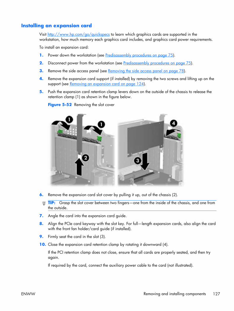
Installing an expansion card
Visit http://www.hp.com/go/quickspecs to learn which graphics cards are supported in theworkstation, how much memory each graphics card includes, and graphics card power requirements.
To install an expansion card:
1. Power down the workstation (see Predisassembly procedures on page 75).
2. Disconnect power from the workstation (see Predisassembly procedures on page 75).
3. Remove the side access panel (see Removing the side access panel on page 78).
4. Remove the expansion card support (if installed) by removing the two screws and lifting up on thesupport (see Removing an expansion card on page 124).
5. Push the expansion card retention clamp levers down on the outside of the chassis to release theretention clamp (1) as shown in the figure below.
Figure 5-52 Removing the slot cover
6. Remove the expansion card slot cover by pulling it up, out of the chassis (2).
TIP: Grasp the slot cover between two fingers—one from the inside of the chassis, and one fromthe outside.
7. Angle the card into the expansion card guide.
8. Align the PCIe card keyway with the slot key. For full—length expansion cards, also align the cardwith the front fan holder/card guide (if installed).
9. Firmly seat the card in the slot (3).
10. Close the expansion card retention clamp by rotating it downward (4).
If the PCI retention clamp does not close, ensure that all cards are properly seated, and then tryagain.
If required by the card, connect the auxiliary power cable to the card (not illustrated).
ENWW Removing and installing components 127
BatteryThis section describes how to remove and install the battery.
The battery that comes with the workstation provides power to the real-time clock and has a minimumlifetime of about three years.
WARNING! This workstation includes a lithium battery. There is a risk of fire and chemical burn ifthe battery is handled improperly. Do not disassemble, crush, puncture, short external contacts, disposein water or fire, or expose it to temperatures higher than 60°C (140°F).
CAUTION: Before removing the battery, back up the CMOS settings in case they are lost when thebattery is removed. To back up the CMOS settings, select the Save to Diskette option in theComputer Setup (F10) Utility.
NOTE: Do not dispose of batteries, battery packs, and accumulators with general household waste.
Removing the battery
To remove the battery:
1. Power down the workstation (see Predisassembly procedures on page 75).
2. Disconnect power from the workstation (see Predisassembly procedures on page 75).
3. Remove the side access panel (see Removing the side access panel on page 78).
4. On the system board, press the release tab of the battery holder.
128 Chapter 5 Replacing components ENWW

5. Pull the tab (1) on the battery holder, and then lift it straight up (2), as shown in the followingfigure.
Figure 5-53 Removing the battery
Installing the battery
To install the battery:
1. Confirm the polarity (positive or negative) of the battery to position it correctly in the batteryholder.
2. Place the battery edge under the plastic housing tab and press gently until it snaps into place.
Hard disk driveThis section provides information to successfully remove and install a hard disk drive.
Removing the hard disk drive
To remove a hard disk drive:
1. Power down the workstation (see Predisassembly procedures on page 75).
2. Disconnect power from the workstation (see Predisassembly procedures on page 75).
3. Remove the side access panel (see Removing the side access panel on page 78).
4. Disconnect the power and data cables from the drive.
ENWW Removing and installing components 129
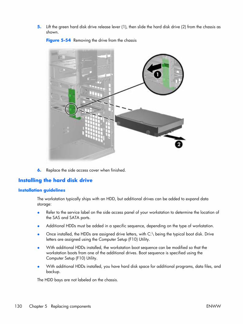
5. Lift the green hard disk drive release lever (1), then slide the hard disk drive (2) from the chassis asshown.
Figure 5-54 Removing the drive from the chassis
6. Replace the side access cover when finished.
Installing the hard disk drive
Installation guidelines
The workstation typically ships with an HDD, but additional drives can be added to expand datastorage:
● Refer to the service label on the side access panel of your workstation to determine the location ofthe SAS and SATA ports.
● Additional HDDs must be added in a specific sequence, depending on the type of workstation.
● Once installed, the HDDs are assigned drive letters, with C:\ being the typical boot disk. Driveletters are assigned using the Computer Setup (F10) Utility.
● With additional HDDs installed, the workstation boot sequence can be modified so that theworkstation boots from one of the additional drives. Boot sequence is specified using theComputer Setup (F10) Utility.
● With additional HDDs installed, you have hard disk space for additional programs, data files, andbackup.
The HDD bays are not labeled on the chassis.
130 Chapter 5 Replacing components ENWW
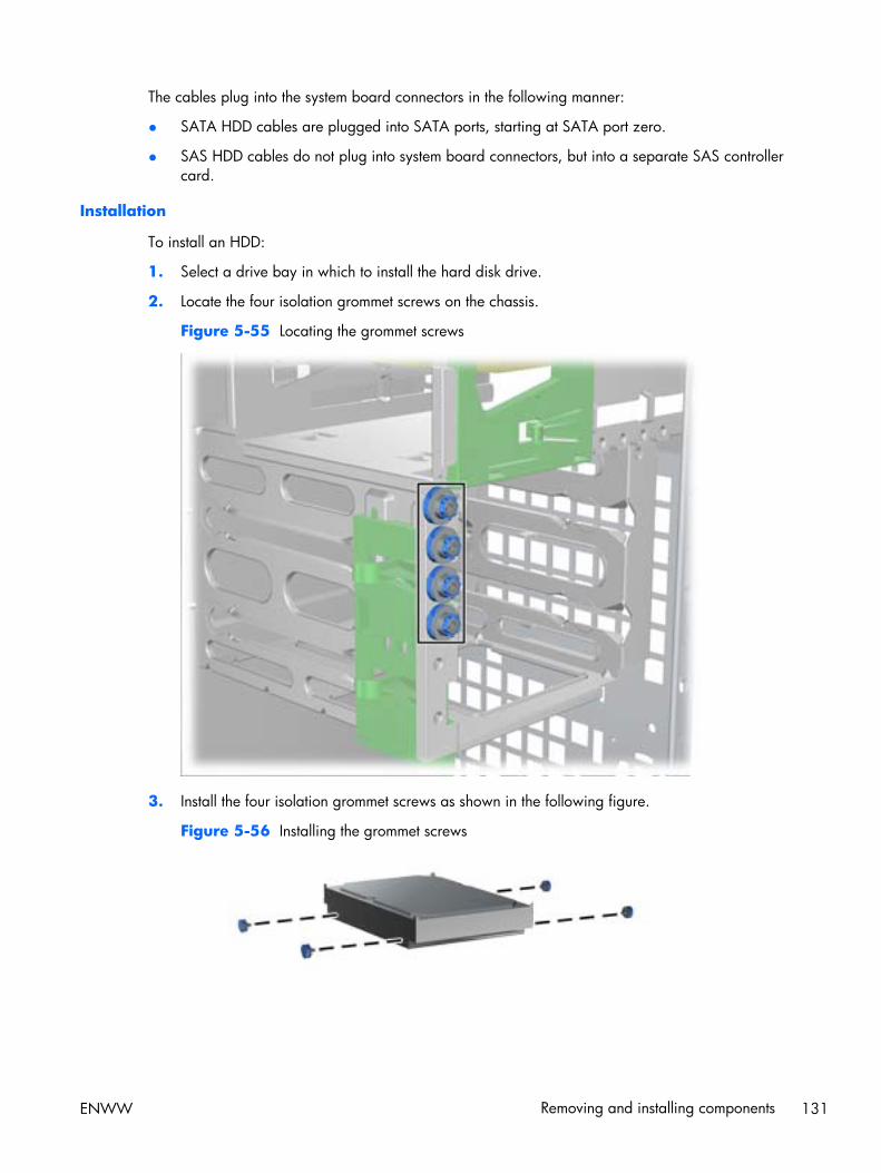
The cables plug into the system board connectors in the following manner:
● SATA HDD cables are plugged into SATA ports, starting at SATA port zero.
● SAS HDD cables do not plug into system board connectors, but into a separate SAS controllercard.
Installation
To install an HDD:
1. Select a drive bay in which to install the hard disk drive.
2. Locate the four isolation grommet screws on the chassis.
Figure 5-55 Locating the grommet screws
3. Install the four isolation grommet screws as shown in the following figure.
Figure 5-56 Installing the grommet screws
ENWW Removing and installing components 131
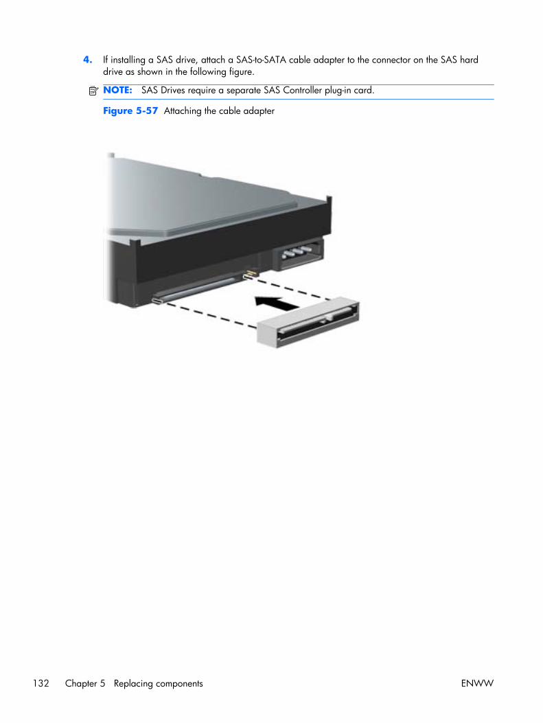
4. If installing a SAS drive, attach a SAS-to-SATA cable adapter to the connector on the SAS harddrive as shown in the following figure.
NOTE: SAS Drives require a separate SAS Controller plug-in card.
Figure 5-57 Attaching the cable adapter
132 Chapter 5 Replacing components ENWW
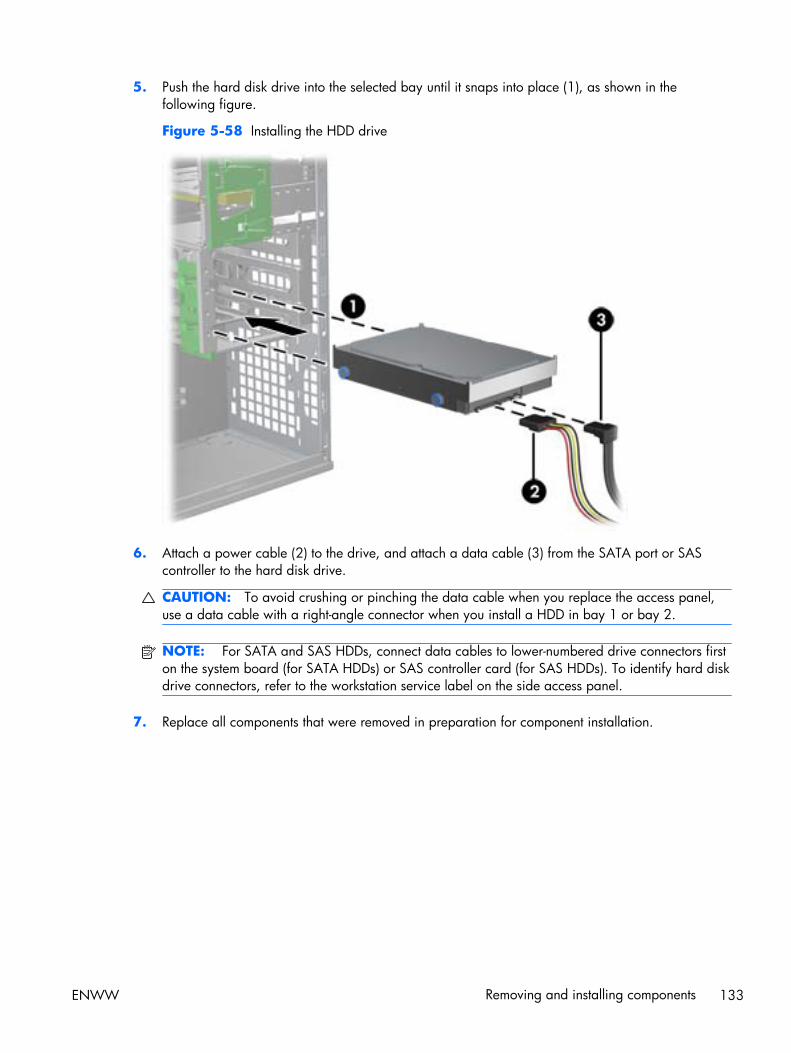
5. Push the hard disk drive into the selected bay until it snaps into place (1), as shown in thefollowing figure.
Figure 5-58 Installing the HDD drive
6. Attach a power cable (2) to the drive, and attach a data cable (3) from the SATA port or SAScontroller to the hard disk drive.
CAUTION: To avoid crushing or pinching the data cable when you replace the access panel,use a data cable with a right-angle connector when you install a HDD in bay 1 or bay 2.
NOTE: For SATA and SAS HDDs, connect data cables to lower-numbered drive connectors firston the system board (for SATA HDDs) or SAS controller card (for SAS HDDs). To identify hard diskdrive connectors, refer to the workstation service label on the side access panel.
7. Replace all components that were removed in preparation for component installation.
ENWW Removing and installing components 133
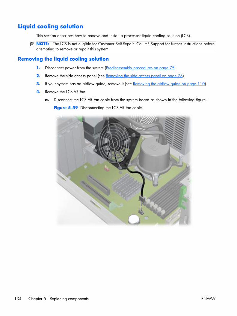
Liquid cooling solutionThis section describes how to remove and install a processor liquid cooling solution (LCS).
NOTE: The LCS is not eligible for Customer Self-Repair. Call HP Support for further instructions beforeattempting to remove or repair this system.
Removing the liquid cooling solution
1. Disconnect power from the system (Predisassembly procedures on page 75).
2. Remove the side access panel (see Removing the side access panel on page 78).
3. If your system has an airflow guide, remove it (see Removing the airflow guide on page 110).
4. Remove the LCS VR fan.
a. Disconnect the LCS VR fan cable from the system board as shown in the following figure.
Figure 5-59 Disconnecting the LCS VR fan cable
134 Chapter 5 Replacing components ENWW
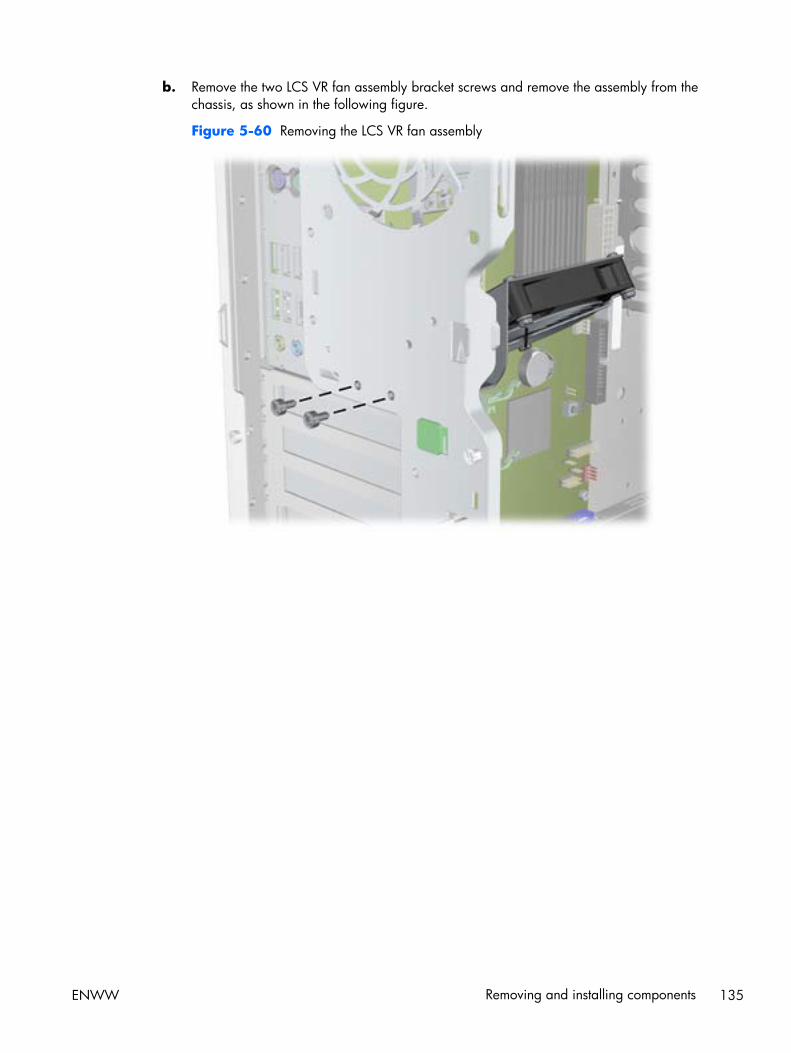
b. Remove the two LCS VR fan assembly bracket screws and remove the assembly from thechassis, as shown in the following figure.
Figure 5-60 Removing the LCS VR fan assembly
ENWW Removing and installing components 135

5. Disconnect the rear system fan cable from the system board as shown in the following figure.
Figure 5-61 Disconnecting the rear system fan cable
136 Chapter 5 Replacing components ENWW
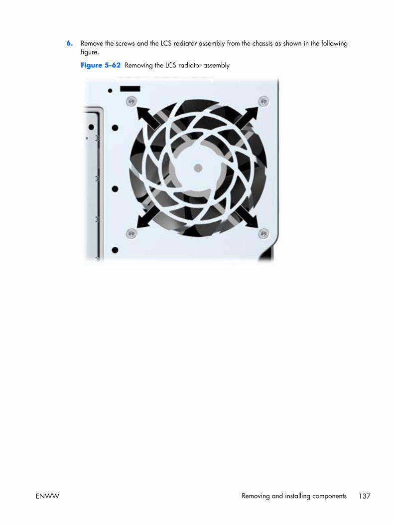
6. Remove the screws and the LCS radiator assembly from the chassis as shown in the followingfigure.
Figure 5-62 Removing the LCS radiator assembly
ENWW Removing and installing components 137
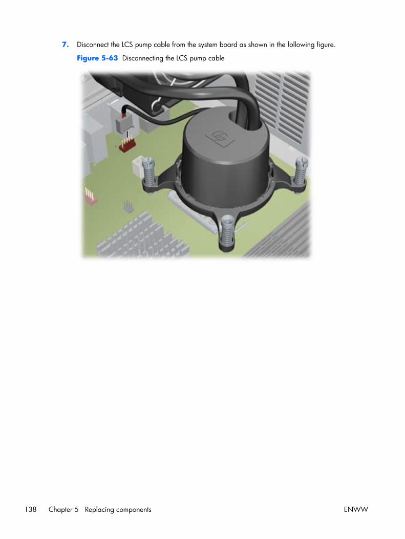
7. Disconnect the LCS pump cable from the system board as shown in the following figure.
Figure 5-63 Disconnecting the LCS pump cable
138 Chapter 5 Replacing components ENWW
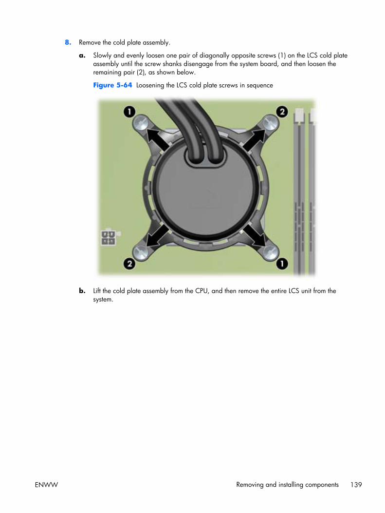
8. Remove the cold plate assembly.
a. Slowly and evenly loosen one pair of diagonally opposite screws (1) on the LCS cold plateassembly until the screw shanks disengage from the system board, and then loosen theremaining pair (2), as shown below.
Figure 5-64 Loosening the LCS cold plate screws in sequence
b. Lift the cold plate assembly from the CPU, and then remove the entire LCS unit from thesystem.
ENWW Removing and installing components 139
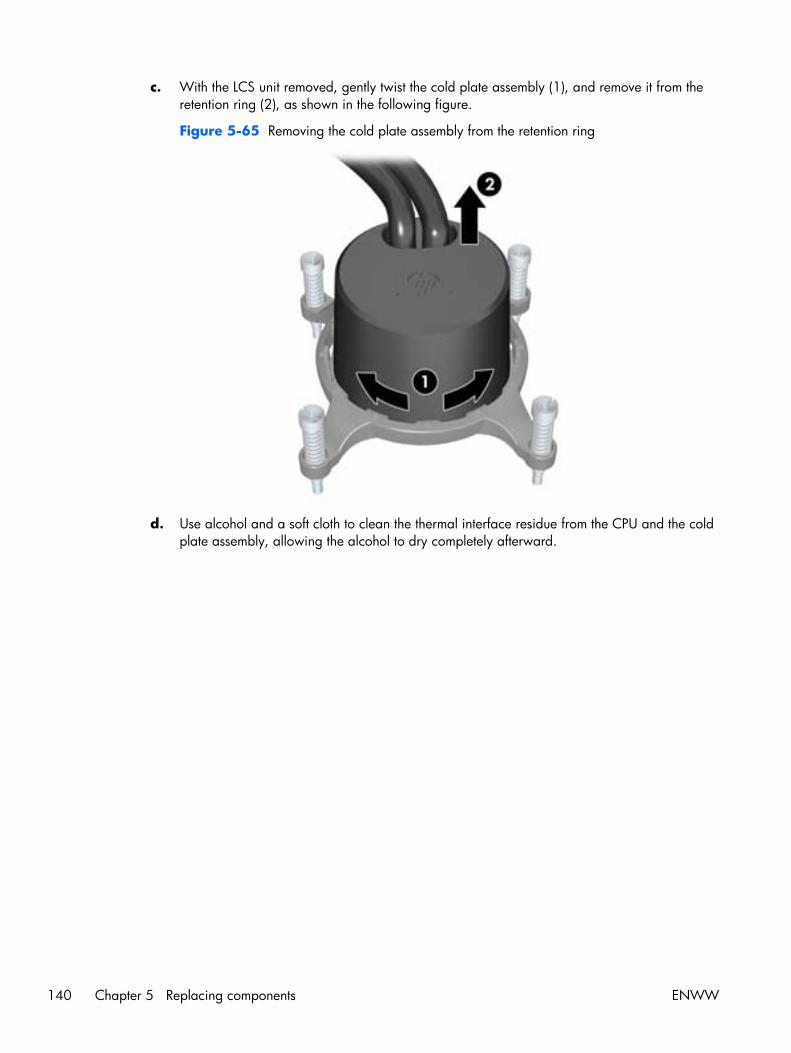
c. With the LCS unit removed, gently twist the cold plate assembly (1), and remove it from theretention ring (2), as shown in the following figure.
Figure 5-65 Removing the cold plate assembly from the retention ring
d. Use alcohol and a soft cloth to clean the thermal interface residue from the CPU and the coldplate assembly, allowing the alcohol to dry completely afterward.
140 Chapter 5 Replacing components ENWW
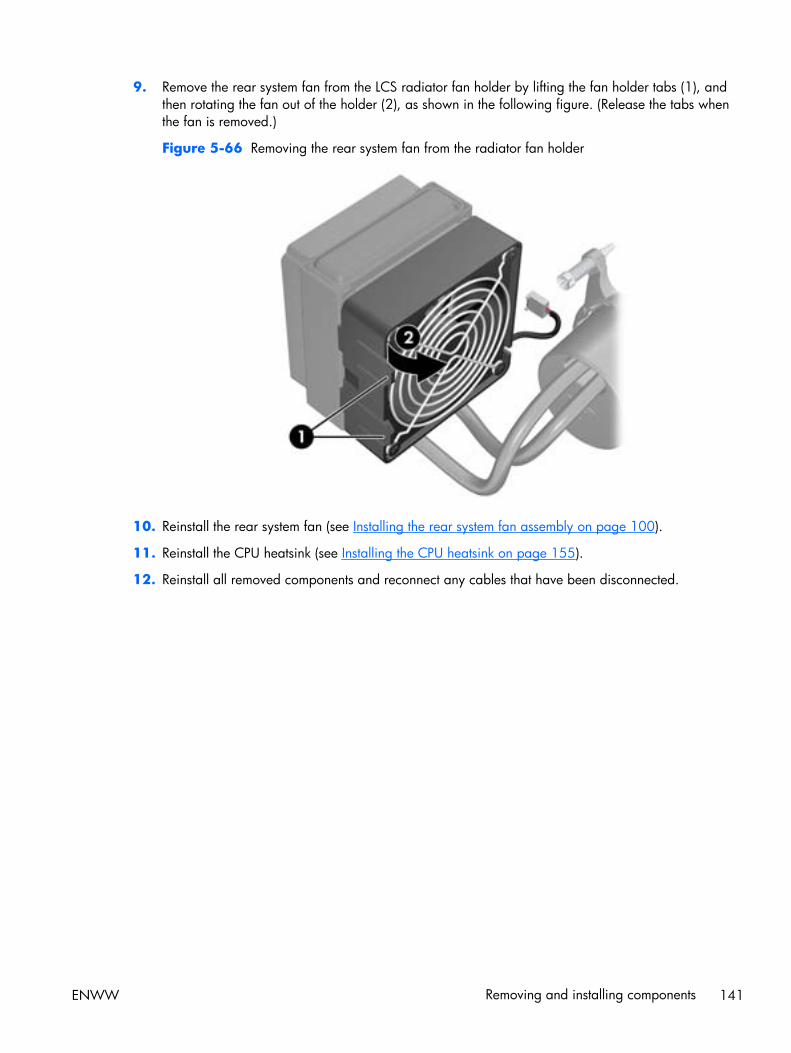
9. Remove the rear system fan from the LCS radiator fan holder by lifting the fan holder tabs (1), andthen rotating the fan out of the holder (2), as shown in the following figure. (Release the tabs whenthe fan is removed.)
Figure 5-66 Removing the rear system fan from the radiator fan holder
10. Reinstall the rear system fan (see Installing the rear system fan assembly on page 100).
11. Reinstall the CPU heatsink (see Installing the CPU heatsink on page 155).
12. Reinstall all removed components and reconnect any cables that have been disconnected.
ENWW Removing and installing components 141
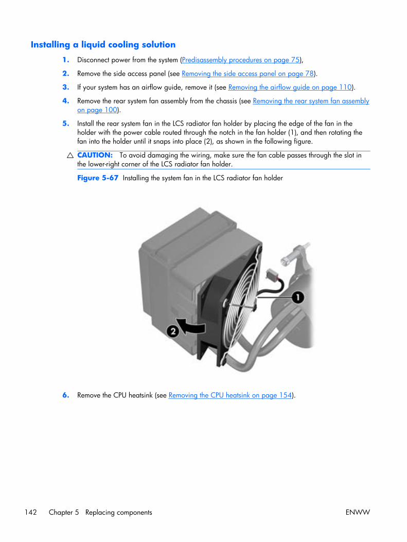
Installing a liquid cooling solution
1. Disconnect power from the system (Predisassembly procedures on page 75),
2. Remove the side access panel (see Removing the side access panel on page 78).
3. If your system has an airflow guide, remove it (see Removing the airflow guide on page 110).
4. Remove the rear system fan assembly from the chassis (see Removing the rear system fan assemblyon page 100).
5. Install the rear system fan in the LCS radiator fan holder by placing the edge of the fan in theholder with the power cable routed through the notch in the fan holder (1), and then rotating thefan into the holder until it snaps into place (2), as shown in the following figure.
CAUTION: To avoid damaging the wiring, make sure the fan cable passes through the slot inthe lower-right corner of the LCS radiator fan holder.
Figure 5-67 Installing the system fan in the LCS radiator fan holder
6. Remove the CPU heatsink (see Removing the CPU heatsink on page 154).
142 Chapter 5 Replacing components ENWW
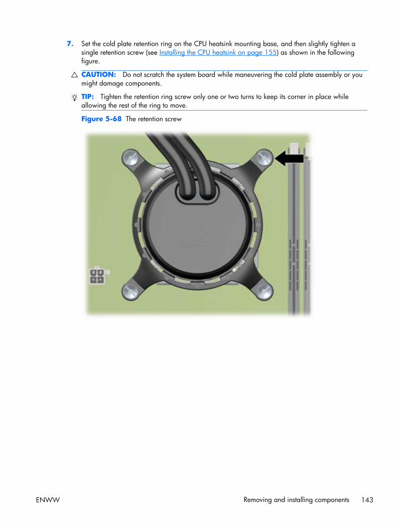
7. Set the cold plate retention ring on the CPU heatsink mounting base, and then slightly tighten asingle retention screw (see Installing the CPU heatsink on page 155) as shown in the followingfigure.
CAUTION: Do not scratch the system board while maneuvering the cold plate assembly or youmight damage components.
TIP: Tighten the retention ring screw only one or two turns to keep its corner in place whileallowing the rest of the ring to move.
Figure 5-68 The retention screw
ENWW Removing and installing components 143
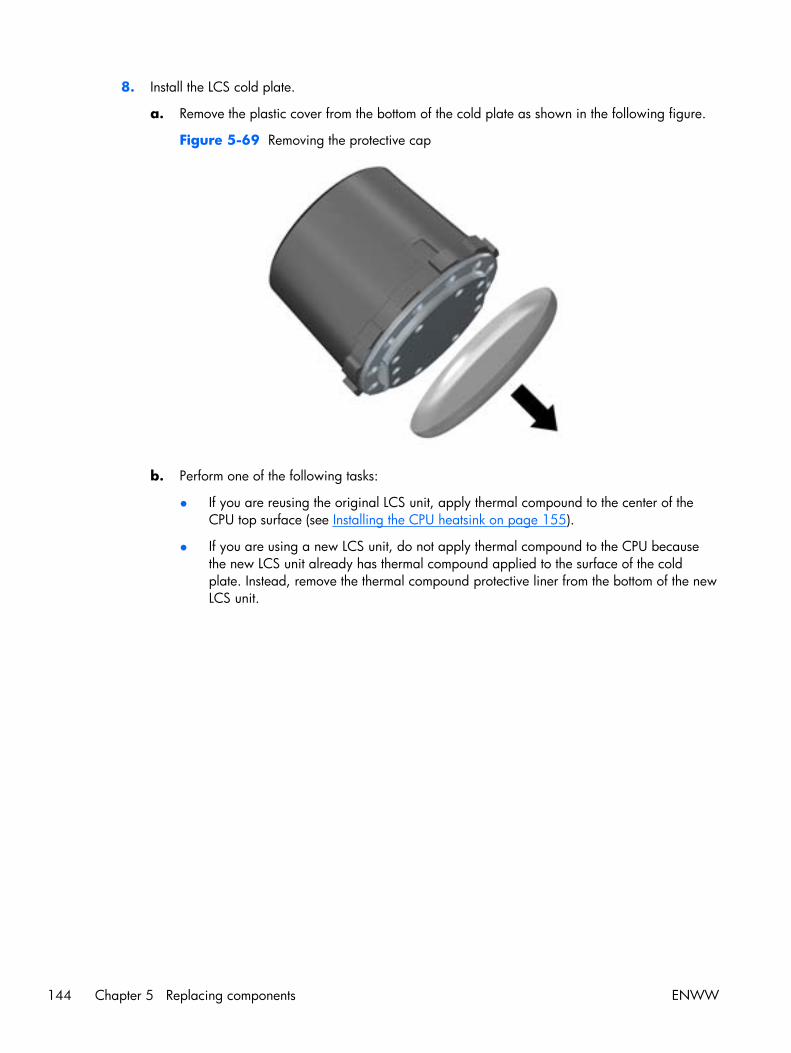
8. Install the LCS cold plate.
a. Remove the plastic cover from the bottom of the cold plate as shown in the following figure.
Figure 5-69 Removing the protective cap
b. Perform one of the following tasks:
● If you are reusing the original LCS unit, apply thermal compound to the center of theCPU top surface (see Installing the CPU heatsink on page 155).
● If you are using a new LCS unit, do not apply thermal compound to the CPU becausethe new LCS unit already has thermal compound applied to the surface of the coldplate. Instead, remove the thermal compound protective liner from the bottom of the newLCS unit.
144 Chapter 5 Replacing components ENWW

c. Lift the edge of the LCS cold plate retention ring, align the tabs on the retention ring with theslots in the cold plate, and then set the cold plate into the retention ring on the CPU as shownin the following figure.
TIP: Ensure that the HP logo is positioned horizontally as shown in the figure.
Figure 5-70 Positioning the LCS cold plate
d. Gently twist the cold plate body until it locks into place in the retention ring as shown in theprevious figure.
ENWW Removing and installing components 145
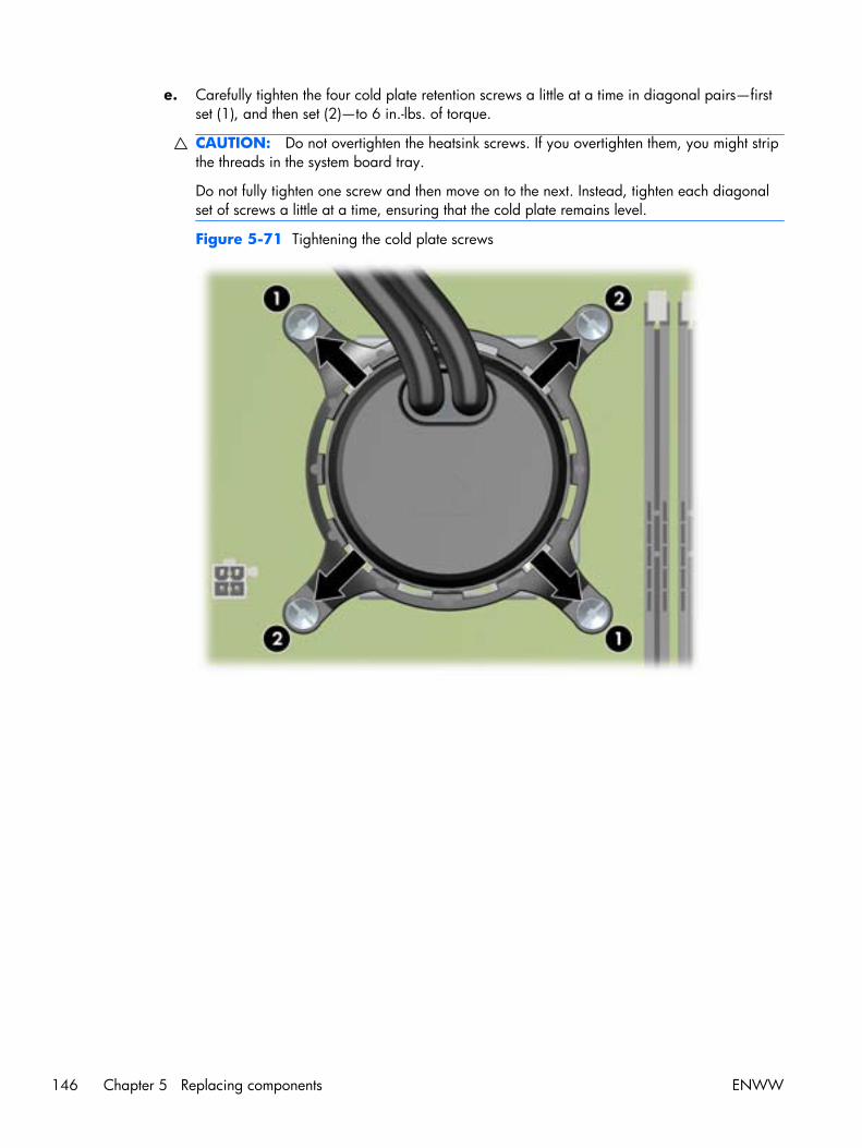
e. Carefully tighten the four cold plate retention screws a little at a time in diagonal pairs—firstset (1), and then set (2)—to 6 in.-lbs. of torque.
CAUTION: Do not overtighten the heatsink screws. If you overtighten them, you might stripthe threads in the system board tray.
Do not fully tighten one screw and then move on to the next. Instead, tighten each diagonalset of screws a little at a time, ensuring that the cold plate remains level.
Figure 5-71 Tightening the cold plate screws
146 Chapter 5 Replacing components ENWW
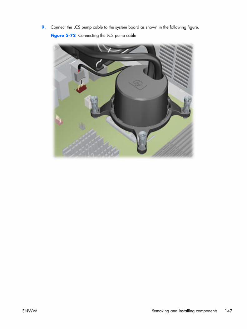
9. Connect the LCS pump cable to the system board as shown in the following figure.
Figure 5-72 Connecting the LCS pump cable
ENWW Removing and installing components 147
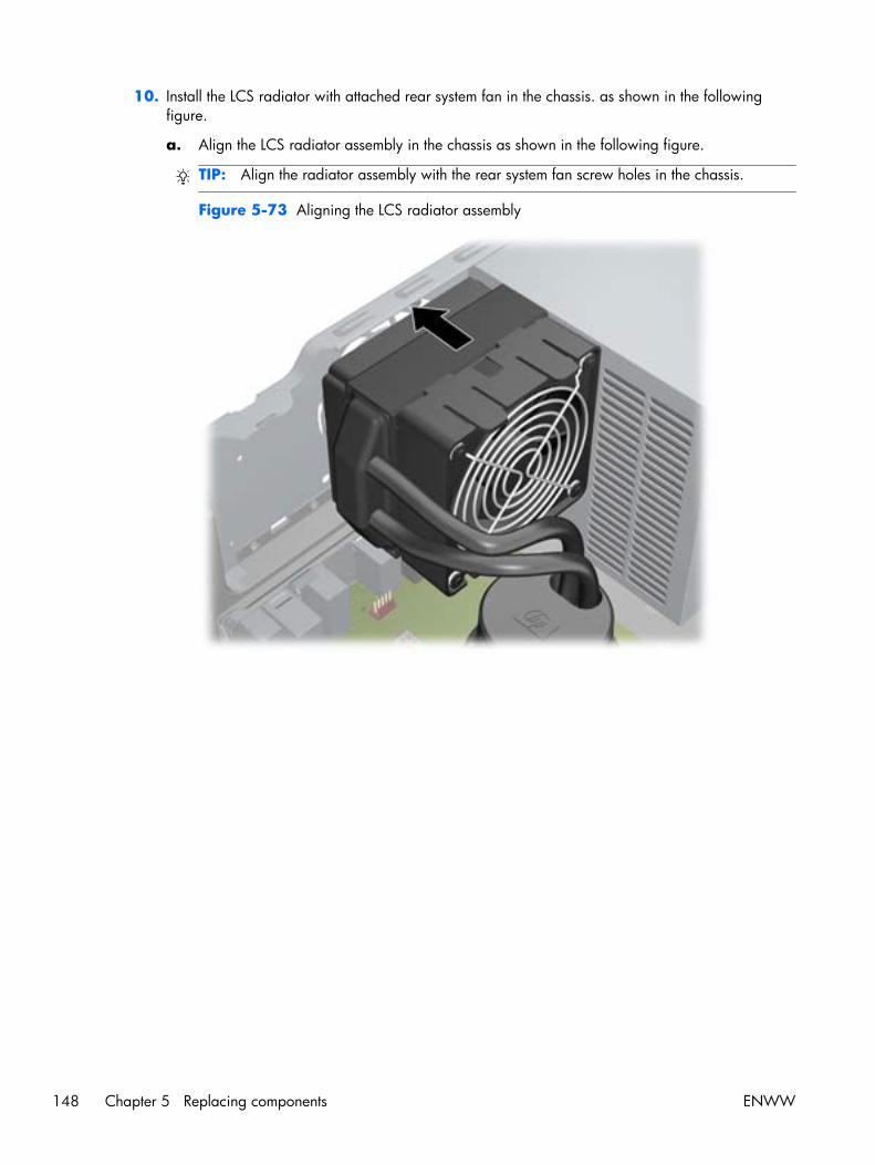
10. Install the LCS radiator with attached rear system fan in the chassis. as shown in the followingfigure.
a. Align the LCS radiator assembly in the chassis as shown in the following figure.
TIP: Align the radiator assembly with the rear system fan screw holes in the chassis.
Figure 5-73 Aligning the LCS radiator assembly
148 Chapter 5 Replacing components ENWW
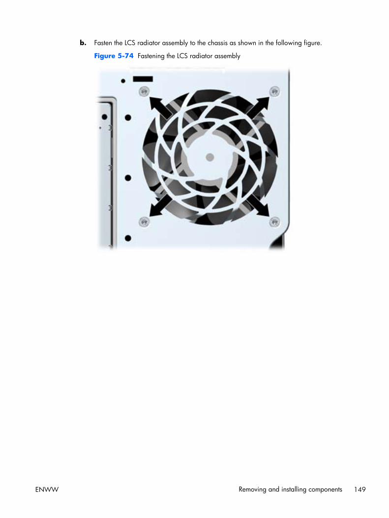
b. Fasten the LCS radiator assembly to the chassis as shown in the following figure.
Figure 5-74 Fastening the LCS radiator assembly
ENWW Removing and installing components 149
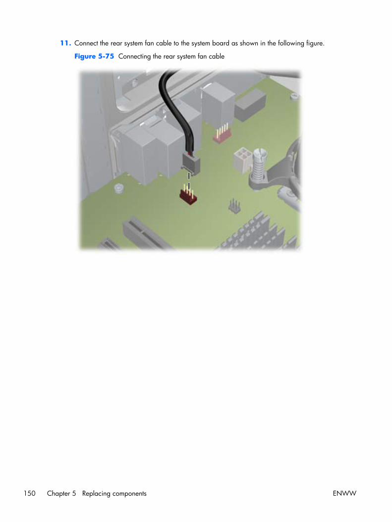
11. Connect the rear system fan cable to the system board as shown in the following figure.
Figure 5-75 Connecting the rear system fan cable
150 Chapter 5 Replacing components ENWW
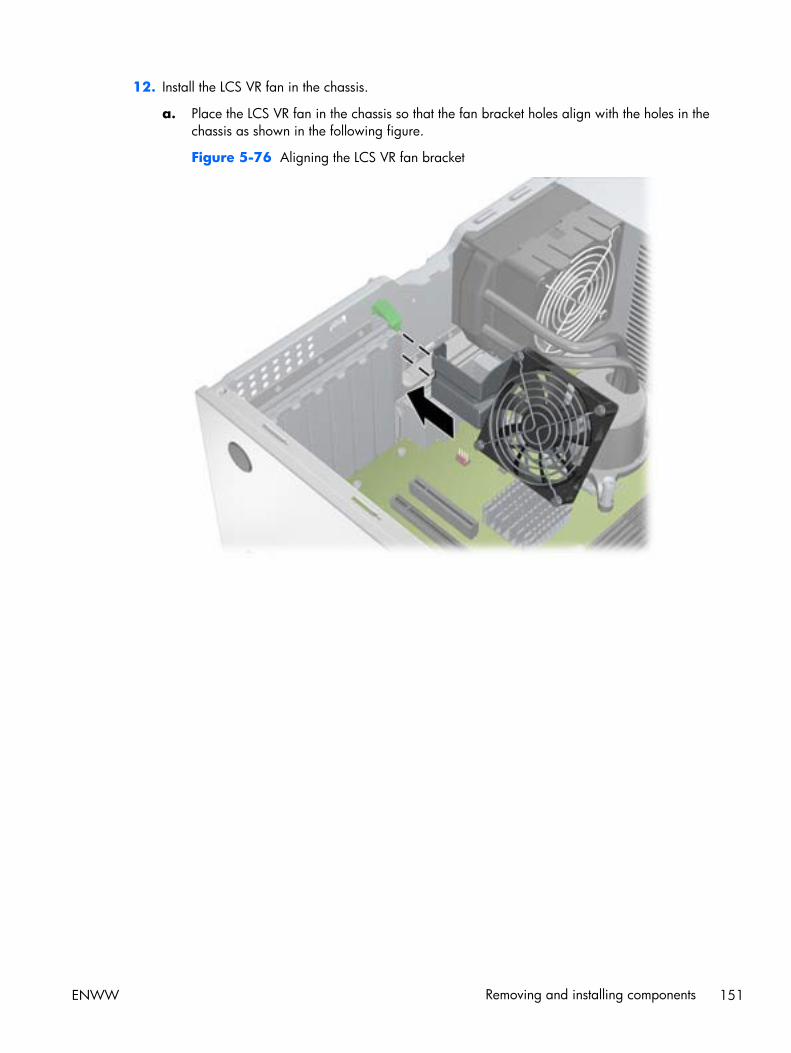
12. Install the LCS VR fan in the chassis.
a. Place the LCS VR fan in the chassis so that the fan bracket holes align with the holes in thechassis as shown in the following figure.
Figure 5-76 Aligning the LCS VR fan bracket
ENWW Removing and installing components 151
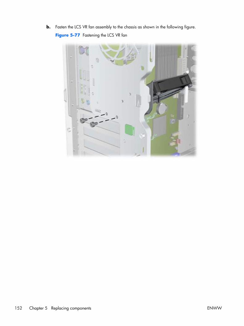
b. Fasten the LCS VR fan assembly to the chassis as shown in the following figure.
Figure 5-77 Fastening the LCS VR fan
152 Chapter 5 Replacing components ENWW

c. Connect the LCS VR fan cable to the system board as shown in the following figure.
Figure 5-78 Connecting the LCS VR fan cable
13. Reinstall all removed components and reconnect any cables that have been disconnected.
ENWW Removing and installing components 153
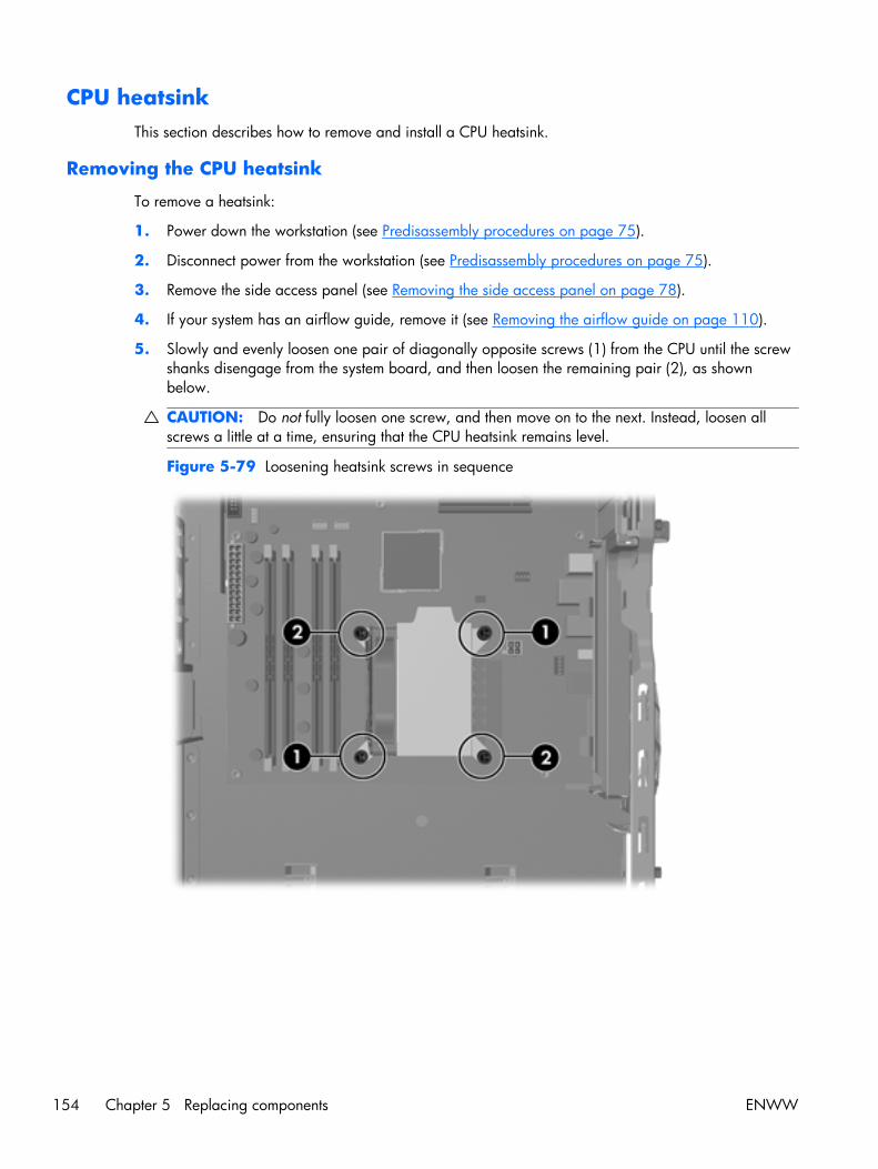
CPU heatsinkThis section describes how to remove and install a CPU heatsink.
Removing the CPU heatsink
To remove a heatsink:
1. Power down the workstation (see Predisassembly procedures on page 75).
2. Disconnect power from the workstation (see Predisassembly procedures on page 75).
3. Remove the side access panel (see Removing the side access panel on page 78).
4. If your system has an airflow guide, remove it (see Removing the airflow guide on page 110).
5. Slowly and evenly loosen one pair of diagonally opposite screws (1) from the CPU until the screwshanks disengage from the system board, and then loosen the remaining pair (2), as shownbelow.
CAUTION: Do not fully loosen one screw, and then move on to the next. Instead, loosen allscrews a little at a time, ensuring that the CPU heatsink remains level.
Figure 5-79 Loosening heatsink screws in sequence
154 Chapter 5 Replacing components ENWW
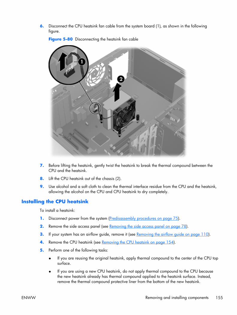
6. Disconnect the CPU heatsink fan cable from the system board (1), as shown in the followingfigure.
Figure 5-80 Disconnecting the heatsink fan cable
7. Before lifting the heatsink, gently twist the heatsink to break the thermal compound between theCPU and the heatsink.
8. Lift the CPU heatsink out of the chassis (2).
9. Use alcohol and a soft cloth to clean the thermal interface residue from the CPU and the heatsink,allowing the alcohol on the CPU and CPU heatsink to dry completely.
Installing the CPU heatsink
To install a heatsink:
1. Disconnect power from the system (Predisassembly procedures on page 75).
2. Remove the side access panel (see Removing the side access panel on page 78).
3. If your system has an airflow guide, remove it (see Removing the airflow guide on page 110).
4. Remove the CPU heatsink (see Removing the CPU heatsink on page 154).
5. Perform one of the following tasks:
● If you are reusing the original heatsink, apply thermal compound to the center of the CPU topsurface.
● If you are using a new CPU heatsink, do not apply thermal compound to the CPU becausethe new heatsink already has thermal compound applied to the heatsink surface. Instead,remove the thermal compound protective liner from the bottom of the new heatsink.
ENWW Removing and installing components 155
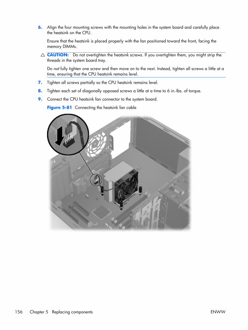
6. Align the four mounting screws with the mounting holes in the system board and carefully placethe heatsink on the CPU.
Ensure that the heatsink is placed properly with the fan positioned toward the front, facing thememory DIMMs.
CAUTION: Do not overtighten the heatsink screws. If you overtighten them, you might strip thethreads in the system board tray.
Do not fully tighten one screw and then move on to the next. Instead, tighten all screws a little at atime, ensuring that the CPU heatsink remains level.
7. Tighten all screws partially so the CPU heatsink remains level.
8. Tighten each set of diagonally opposed screws a little at a time to 6 in.-lbs. of torque.
9. Connect the CPU heatsink fan connector to the system board.
Figure 5-81 Connecting the heatsink fan cable
156 Chapter 5 Replacing components ENWW

CPUThis section describes how to remove and install a CPU.
Removing a CPU
To remove a CPU:
1. Power down the workstation (see Predisassembly procedures on page 75).
2. Disconnect power from the workstation (see Predisassembly procedures on page 75).
3. Remove the side access panel (see Removing the side access panel on page 78).
4. If your system has an airflow guide, remove it (see Removing the airflow guide on page 110).
5. Remove the CPU heatsink (see Removing the CPU heatsink on page 154).
6. Raise the CPU socket lever (1), and then open the cover (2), as shown in the following figure.
Figure 5-82 Removing a CPU
CAUTION: Do not touch the CPU socket contacts or the gold pads underneath the CPU. Useextreme care and handle the CPU only by the edges.
7. Pull the CPU straight out of the socket (3), and store the CPU in a static free container in a safeplace where it cannot be damaged
ENWW Removing and installing components 157

Installing a CPU
NOTE: HP recommends that you do not swap processors (CPUs) from one system board to another.
To install a CPU:
1. Power down the workstation (see Predisassembly procedures on page 75).
2. Disconnect power from the workstation (see Predisassembly procedures on page 75).
3. Remove the side access panel (see Removing the side access panel on page 78).
4. If your system has an airflow guide, remove it (see Removing the airflow guide on page 110).
5. Remove the CPU heatsink (see Removing the CPU heatsink on page 154).
6. Remove the CPU (see Removing a CPU on page 157).
7. Using extreme care, fully raise the CPU socket lever and cover.
CAUTION: The CPU socket contacts are delicate. To avoid bending the contacts, use extremecare when installing the CPU in the socket.
8. Align the notches in the CPU base with the tabs on the socket as shown in the figure below.
Seat the CPU into the socket. Ensure that the underside of the CPU is level with the top of the CPUsocket.
Figure 5-83 Seating the CPU
9. Close the CPU cover plate by lightly pressing down on the CPU cover plate while closing thesocket lever.
10. Replace the CPU heatsink (see Installing the CPU heatsink on page 155).
158 Chapter 5 Replacing components ENWW
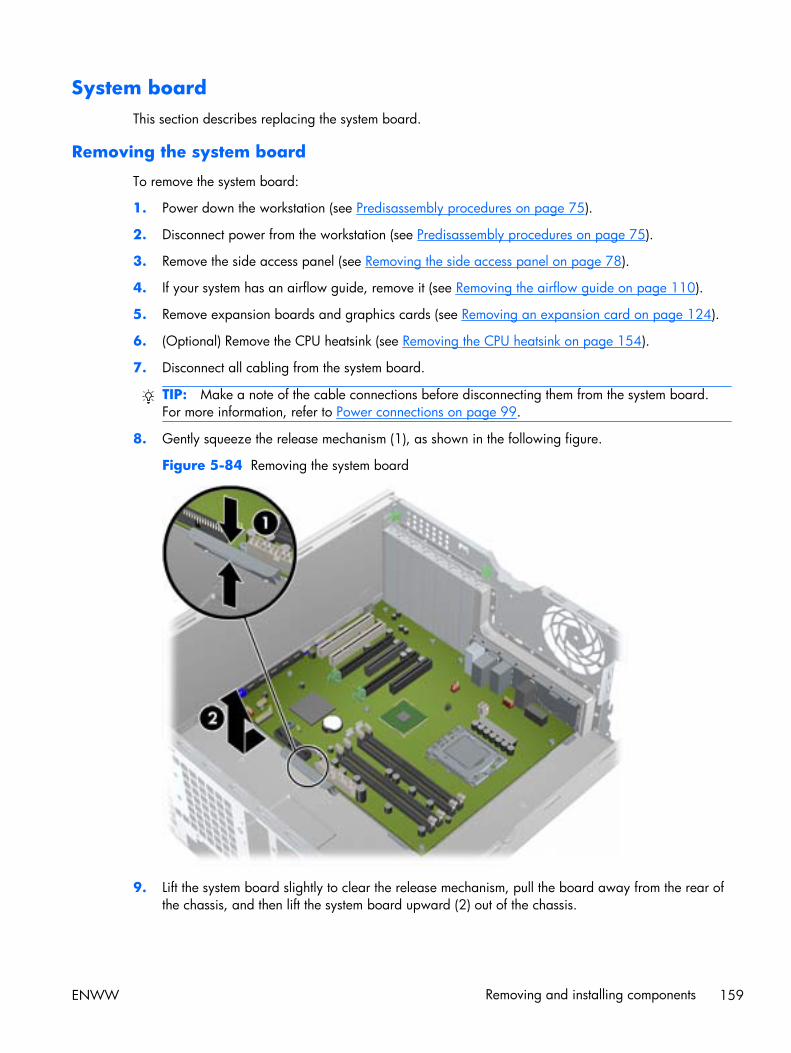
System boardThis section describes replacing the system board.
Removing the system board
To remove the system board:
1. Power down the workstation (see Predisassembly procedures on page 75).
2. Disconnect power from the workstation (see Predisassembly procedures on page 75).
3. Remove the side access panel (see Removing the side access panel on page 78).
4. If your system has an airflow guide, remove it (see Removing the airflow guide on page 110).
5. Remove expansion boards and graphics cards (see Removing an expansion card on page 124).
6. (Optional) Remove the CPU heatsink (see Removing the CPU heatsink on page 154).
7. Disconnect all cabling from the system board.
TIP: Make a note of the cable connections before disconnecting them from the system board.For more information, refer to Power connections on page 99.
8. Gently squeeze the release mechanism (1), as shown in the following figure.
Figure 5-84 Removing the system board
9. Lift the system board slightly to clear the release mechanism, pull the board away from the rear ofthe chassis, and then lift the system board upward (2) out of the chassis.
ENWW Removing and installing components 159
TIP: If you leave the heatsink installed, you can grasp it and use it to guide the system board outof the chassis.
Installing the system board
To install the system board:
1. Insert the system board with the rear chassis side of the board tilted slightly downward.
2. Push back on the board while maintaining downward pressure on the board to clear the releasemechanism. The latch should click into place.
3. Reinstall all removed components and cables. (Refer to Power connections on page 99 to identifypower cables.)
160 Chapter 5 Replacing components ENWW
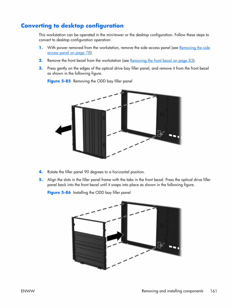
Converting to desktop configurationThis workstation can be operated in the mini-tower or the desktop configuration. Follow these steps toconvert to desktop configuration operation:
1. With power removed from the workstation, remove the side access panel (see Removing the sideaccess panel on page 78).
2. Remove the front bezel from the workstation (see Removing the front bezel on page 83).
3. Press gently on the edges of the optical drive bay filler panel, and remove it from the front bezelas shown in the following figure.
Figure 5-85 Removing the ODD bay filler panel
4. Rotate the filler panel 90 degrees to a horizontal position.
5. Align the slots in the filler panel frame with the tabs in the front bezel. Press the optical drive fillerpanel back into the front bezel until it snaps into place as shown in the following figure.
Figure 5-86 Installing the ODD bay filler panel
ENWW Removing and installing components 161
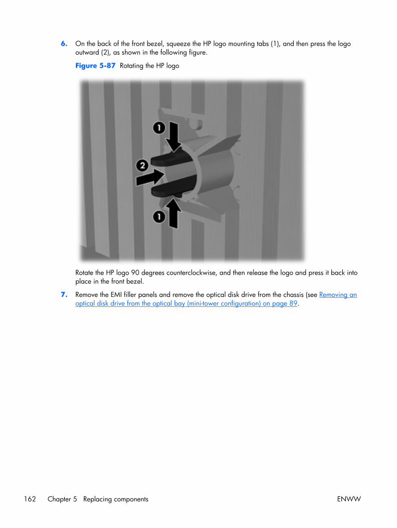
6. On the back of the front bezel, squeeze the HP logo mounting tabs (1), and then press the logooutward (2), as shown in the following figure.
Figure 5-87 Rotating the HP logo
Rotate the HP logo 90 degrees counterclockwise, and then release the logo and press it back intoplace in the front bezel.
7. Remove the EMI filler panels and remove the optical disk drive from the chassis (see Removing anoptical disk drive from the optical bay (mini-tower configuration) on page 89.
162 Chapter 5 Replacing components ENWW

8. Rotate the EMI filler panels and the optical drive 90 degrees as shown in the figure below, andthen reinstall them (see Installing an optical drive (desktop configuration) on page 95.
Figure 5-88 Reinstalling the optical drive
9. Replace the front bezel (see Installing the front bezel on page 83) and the side access panel (seeInstalling the side access panel on page 78) when finished.
Product recyclingHP encourages customers to recycle used electronic hardware, HP original print cartridges, andrechargeable batteries.
For information about recycling HP components or products, see http://www.hp.com/go/recycle.
ENWW Product recycling 163
6 Diagnostics and troubleshooting
This chapter describes the tools available for diagnosing and troubleshooting system issues, andincludes these topics:
Topics
Calling technical support on page 165
Locating ID labels on page 165
Locating warranty information on page 167
Diagnosis guidelines on page 168
Troubleshooting checklist on page 170
HP troubleshooting resources and tools on page 170
Troubleshooting scenarios and solutions on page 173
Self-troubleshooting with HP Vision Diagnostics on page 184
Diagnostic codes and errors on page 195
164 Chapter 6 Diagnostics and troubleshooting ENWW
Calling technical supportAt times you might encounter an issue that requires technical support. When you call technical support:
● Have the workstation readily accessible.
● Write down the workstation serial numbers, product numbers, model names, and model numbersand have them in front of you.
● Note any applicable error messages.
● Note any add-on options.
● Note the operating system.
● Note any third-party hardware or software.
● Note the details of any blinking LEDs on the front of the workstation.
● Note the applications you were using when you encountered the problem.
● Note the power supply BIST status, if applicable.
NOTE: When calling in for service or support, you might be asked for the Product Number (example:PS988AV) of the workstation. If the workstation has a Product Number, it is generally located next tothe 10- or 12-digit Serial Number of the workstation.
NOTE: On most models, the serial number and product number labels can be found on the top panelor side of the workstation and at the rear of the workstation.
For a listing of all worldwide technical support phone numbers, visit http://www.hp.com/support,select your region, and click Contact HP in the upper-left corner.
Locating ID labelsTo assist in troubleshooting, product, serial, and authentication numbers are available on eachworkstation.
ENWW Calling technical support 165

Each HP Workstation has two unique serial number labels (1) and a Certificate of Authentication(COA) label (2) as shown in the figure below.
Figure 6-1 Workstation label locations
In general, the serial number labels can be found on the top panel or on the side of the workstationand at the rear of the workstation (your workstation may look different). Keep this number availablewhen contacting customer service for assistance.
A product number is generally located next to the serial number.
The COA is used for Windows-preinstalled systems only and is generally located on the top panel orside of the workstation near the serial number label. On some workstations, it is located on the bottomof the workstation.
166 Chapter 6 Diagnostics and troubleshooting ENWW

Locating warranty informationTo locate base warranty information, see: http://www.hp.com/support/warranty-lookuptool
To locate an existing Care Pack, see:
To extend a standard product warranty, see http://h20219.www2.hp.com/services/us/en/warranty/carepack-overview.html?jumpid=hpr_R1002_USEN HP Care Pack Services offer upgraded servicelevels to extend and expand a standard product warranty. For additional warranty information:
1. Go to: http://www.hp.com/#Support
2. Under Additional resources, click on Warranty information.
3. Under Select your product, click on Workstations.
4. Under Personal Workstations, click on HP Z400 Workstation. This displays information aboutwarranties, upgrades, extensions.
ENWW Locating warranty information 167

Diagnosis guidelinesIf you encounter a problem with the workstation, monitor, or software, the following sections provide alist of general suggestions that help you isolate and focus on the problem before taking further action.
Diagnosis at startup● Verify that the workstation and monitor are plugged into a working electrical outlet.
● Remove all diskettes, CDs, or USB drive keys from your system before turning it on.
● Verify that the workstation is turned on and the green power light is on.
● If you have installed an operating system other than the factory-installed operating system, checkto be sure that it is supported on your system by visiting http://www.hp.com/go/quickspecs.
● Verify that the monitor is turned on and the green monitor light is on. Note that not all monitors areequipped with LED lights to indicate their functionality.
● Turn up the brightness and contrast controls of the monitor if the monitor is dim.
● If the workstation has multiple video sources and only a single monitor, the monitor must beconnected to the primary display adapter. During startup, the other monitor connectors aredisabled; if the monitor is connected to one of these ports, it will not function after Power-on SelfTest (POST). You can select the default VGA source in Computer Setup (F10).
168 Chapter 6 Diagnostics and troubleshooting ENWW

Diagnosis during operation● Look for blinking LEDs on the front of the workstation. The blinking lights are error codes that will
help you diagnose the problem. Refer to the Diagnostic LED and audible (beep) codeson page 195 section of this document for information on interpreting diagnostic lights andaudible codes.
● Press and hold any key. If the system beeps, then your keyboard is operating correctly.
● Check all cables for loose or incorrect connections.
● Wake the workstation by pressing any key on the keyboard or the power button. If the systemremains in suspend mode, shut down the system by pressing and holding the power button for atleast four seconds, then press the power button again to restart the system. If the system does notshut down, unplug the power cord, wait a few seconds, then plug it in again. If it does not restart,press the power button to start the workstation.
● Reconfigure the workstation after installing a non–plug and play expansion board or other option.
● Be sure that all required device drivers have been installed. For example, if you have connected aprinter, you must install a printer driver.
● If you are working on a network, plug another workstation with a different cable into the networkconnection. There might be a problem with the network plug or cable.
● If you recently added new hardware, remove the hardware and verify if the workstation functionsproperly.
● If you recently installed new software, uninstall the software and verify if the workstation functionsproperly.
● If the screen is blank, plug the monitor into a different video port on the workstation if one isavailable. Alternatively, replace the monitor with a monitor that you know is working properly.
● Upgrade the BIOS. A new release of the BIOS might have been released that supports newfeatures or fixes your problem.
● For more detailed information, see the troubleshooting chapter in the Maintenance and ServiceGuide at http://www.hp.com/support/workstation_manuals.
ENWW Diagnosis guidelines 169

Troubleshooting checklistBefore running diagnostic utilities, use the following checklist to find possible solutions for workstationor software problems.
● Is the workstation and monitor connected to a working electrical outlet?
● Is the workstation powered on?
● Is the green power light illuminated?
● Is the monitor on?
● Is the green monitor light illuminated?
● If the monitor is dim, adjust the monitor brightness and contrast controls.
● Press and hold any key. If the system beeps, the keyboard is operating correctly.
● Check cables for loose or improper connections.
● After installing a non-plug and play (PnP) expansion board or other option (such as a diskettedrive), reconfigure the workstation.
● Are all necessary device drivers installed?
● Have all printer drivers been installed for each application?
● Have you removed diskettes, optical disks, and USB drive keys from the drives before poweringon the workstation?
● Are you running the latest version of BIOS, drivers, and software?
HP troubleshooting resources and toolsThis section provides information on the HP Help and Support Center, E-support, and Helpful Hints fortroubleshooting.
HP Support AssistantThe HP Support Assistant is a customized HP user interface that enhances the Windows Vista and Win7 Help and Support Center functions. This customized utility allows you to access specific informationabout an HP Workstation such as configuration information by clicking Start > Help and Support.The interface also provides customized help and support links to the HP Web site related to the HPWorkstation.
NOTE: The customized HP Support Assistant is not available on Windows XP Professional x32 orx64 Editions, or on Linux.
HP Help and Support CenterThe HP Help and Support Center is a customized HP user interface that enhances the Windows XP Helpand Support Center Help feature. This customized utility allows you to access specific information aboutyour HP Workstation such as configuration information by clicking Start > Help and Support. Theinterface also provides customized help and support links to the HP Web site related to your HPWorkstation.
170 Chapter 6 Diagnostics and troubleshooting ENWW

NOTE: The customized HP Help and Support Center is not available on Windows XP Professionalx64 Edition or on Linux.
NOTE: Currently, HP Help and Support Center does not work on Windows Vista.
E-supportOnline access and support resources include Web-based troubleshooting tools, technical knowledgedatabases, driver and patch downloads, online communities, and product change notification services.
The following Web sites are also available to you:
● http://www.hp.com—Provides useful product information.
● http://www.hp.com/support/workstation_manuals—Provides the latest online documentation.
● http://www.hp.com/go/workstationsupport—Provides technical support information forworkstations.
● http://www.hp.com/support—Provides a listing of the worldwide technical support phonenumbers. Access the telephone numbers by visiting the Web site, then select your region, and clickContact HP in the upper-left corner.
● http://www.hp.com/support/workstation_swdrivers—Provides access to software and drivers forworkstations.
Troubleshooting a problem
To help you troubleshoot problems with your system, HP provides the Business Support Center (BSC).The BSC is a portal to an extensive selection of online tools. To access BSC and troubleshoot a problemwith the workstation, complete the following:
1. Visit http://www.hp.com/go/workstationsupport.
2. Under the Business Support Center menu on the left, select Troubleshoot a problem.
3. Under Select your product (center window), select Workstations (under personalcomputing).
4. Under Select your product, continue with selections as appropriate to the workstation seriesand model, and to the problem you are troubleshooting.
Instant Support and Active Chat
HP Instant Support is a set of Web-based support tools that automate and speed up the resolution ofdesktop computing, tape storage, and printing problems.
Active Chat enables you to electronically submit a support ticket to HP over the Web. When you submita support ticket, Active Chat collects information about the computer and pass it to an online supportspecialist. The collection of information might take up to 30 seconds depending on the computerconfiguration. When you submit a support ticket, you receive a confirmation message containing yourcase ID, the support hours for your location, and the estimated time of response.
For more information about HP Instant Support and Active Chat and how to use them, visithttp://instantsupport.hp.com/
NOTE: This feature is not available on Windows XP Professional x64 Edition or on Linux.
ENWW HP troubleshooting resources and tools 171

Customer Advisories, Customer and Security Bulletins, and Customer Notices
To find advisories, bulletins, and notices:
1. Visit http://www.hp.com/go/workstationsupport.
2. Select the desired product.
3. Under Resources for <your selected product>, select See more….
4. Under Self-Help resources: in the center of the window, choose the desired action andappropriate information in the scroll list to view the index.
Product Change Notifications
Product Change Notifications (PCNs) are proactive notifications for product changes occurring within a30-60 day window of the effective date of the change in the manufacturing process. PCNs givecustomers advanced notice of changes to their product, such as an updated BIOS version that they mayneed to qualify prior to the change taking place. The latest PCNs are located at: http://www.hp.com/go/workstationsupport.
Helpful hintsIf you encounter a problem with the workstation, monitor, or software, the following provides a list ofgeneral suggestions that help you isolate and focus on the problem before taking further action.
At startup
● Verify that the workstation and monitor are plugged into a working electrical outlet.
● Remove all diskettes, optical disks, and USB drive keys from the drives before powering on theworkstation.
● Verify that the workstation is turned on and the green power light is on.
● If you have installed an operating system other than the factory-installed operating system, checkto be sure that it is supported on your system by visiting http://www.hp.com/go/quickspecs.
● Verify that the monitor is turned on and the green monitor light is on.
● Turn up the brightness and contrast controls of the monitor if the monitor is dim.
● If the workstation has multiple video sources and only a single monitor, the monitor must beconnected to the source selected as the primary VGA adapter. During startup, the other monitorconnectors are disabled; if the monitor is connected to one of these ports, it will not function afterPower-on Self Test (POST). You can select the default VGA source in Computer Setup (F10).
During operation
● Look for blinking LEDs on the front of the workstation. The blinking lights are error codes that willhelp you diagnose the problem. Refer to the Diagnostic lights and audible (beep) codes section ofthis document for information on interpreting diagnostic lights and audible codes.
● Press and hold any key. If the system beeps, then your keyboard is operating correctly.
● Check all cables for loose or incorrect connections.
172 Chapter 6 Diagnostics and troubleshooting ENWW
● Wake the workstation by pressing any key on the keyboard or the power button. If the systemremains in suspend mode, shut down the system by pressing and holding the power button for atleast four seconds, then press the power button again to restart the system. If the system does notshut down, unplug the power cord, wait a few seconds, then plug it in again. If it does not restart,press the power button to start the workstation.
● Reconfigure the workstation after installing a non–plug and play expansion board or other option.Refer to the Hardware installation problems section of this document for instructions.
● Be sure that all required device drivers have been installed. For example, if you have connected aprinter, you must install a printer driver.
● If you are working on a network, plug another workstation with a different cable into the networkconnection. There might be a problem with the network plug or cable.
● If you recently added new hardware, remove the hardware and verify if the workstation functionsproperly.
● If you recently installed new software, uninstall the software and verify if the workstation functionsproperly.
● If the screen is blank, plug the monitor into a different video port on the workstation if one isavailable. Alternatively, replace the monitor with a monitor that you know is working properly.
● Upgrade the BIOS. A new release of the BIOS might have been released that supports newfeatures or fixes your problem.
● For more detailed information, see the troubleshooting chapter in the Maintenance andTroubleshooting Guide at http://www.hp.com/support/workstation_manuals.
Customizing the monitor display
You can manually select or change the monitor model, refresh rates, screen resolution, color settings,font sizes, and power management settings. To do so, right-click the desktop, then click Properties tochange display settings. For more information, see the online documentation provided with the graphicscontroller utility or the documentation that came with your monitor.
Troubleshooting scenarios and solutionsThis section presents an extensive overview of various troubleshooting scenarios and possible solutionsfor a Windows-based workstation.
NOTE: For Linux troubleshooting information, refer to the HP Workstations for Linux User Manual athttp://www.hp.com/support/linux_user_manual.
Solving minor problemsTable 6-1 Minor problems
Problem Cause Possible Solution
Workstation appears frozenand does not shut downwhen the power button ispressed.
Software control of thepower switch is notfunctional.
1. Press and hold the power button for at least four seconds until theworkstation shuts down.
2. Disconnect the electrical plug from the outlet.
3. Restart the workstation.
ENWW Troubleshooting scenarios and solutions 173
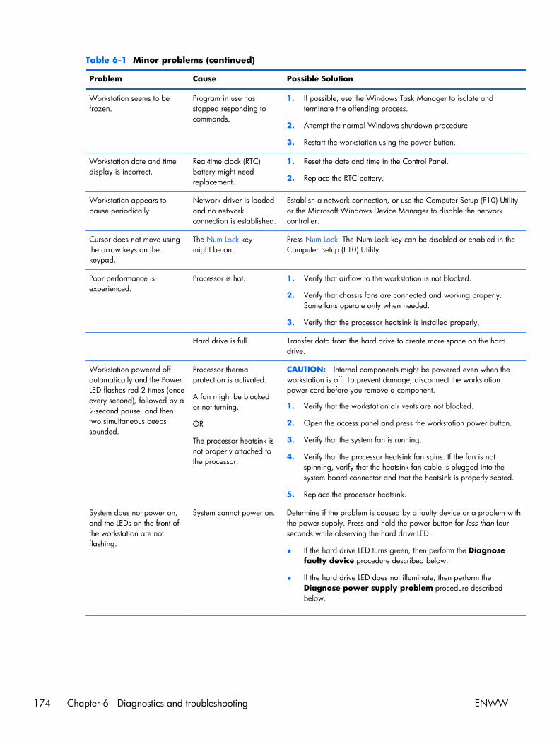
Table 6-1 Minor problems (continued)
Problem Cause Possible Solution
Workstation seems to befrozen.
Program in use hasstopped responding tocommands.
1. If possible, use the Windows Task Manager to isolate andterminate the offending process.
2. Attempt the normal Windows shutdown procedure.
3. Restart the workstation using the power button.
Workstation date and timedisplay is incorrect.
Real-time clock (RTC)battery might needreplacement.
1. Reset the date and time in the Control Panel.
2. Replace the RTC battery.
Workstation appears topause periodically.
Network driver is loadedand no networkconnection is established.
Establish a network connection, or use the Computer Setup (F10) Utilityor the Microsoft Windows Device Manager to disable the networkcontroller.
Cursor does not move usingthe arrow keys on thekeypad.
The Num Lock keymight be on.
Press Num Lock. The Num Lock key can be disabled or enabled in theComputer Setup (F10) Utility.
Poor performance isexperienced.
Processor is hot. 1. Verify that airflow to the workstation is not blocked.
2. Verify that chassis fans are connected and working properly.Some fans operate only when needed.
3. Verify that the processor heatsink is installed properly.
Hard drive is full. Transfer data from the hard drive to create more space on the harddrive.
Workstation powered offautomatically and the PowerLED flashes red 2 times (onceevery second), followed by a2-second pause, and thentwo simultaneous beepssounded.
Processor thermalprotection is activated.
A fan might be blockedor not turning.
OR
The processor heatsink isnot properly attached tothe processor.
CAUTION: Internal components might be powered even when theworkstation is off. To prevent damage, disconnect the workstationpower cord before you remove a component.
1. Verify that the workstation air vents are not blocked.
2. Open the access panel and press the workstation power button.
3. Verify that the system fan is running.
4. Verify that the processor heatsink fan spins. If the fan is notspinning, verify that the heatsink fan cable is plugged into thesystem board connector and that the heatsink is properly seated.
5. Replace the processor heatsink.
System does not power on,and the LEDs on the front ofthe workstation are notflashing.
System cannot power on. Determine if the problem is caused by a faulty device or a problem withthe power supply. Press and hold the power button for less than fourseconds while observing the hard drive LED:
● If the hard drive LED turns green, then perform the Diagnosefaulty device procedure described below.
● If the hard drive LED does not illuminate, then perform theDiagnose power supply problem procedure describedbelow.
174 Chapter 6 Diagnostics and troubleshooting ENWW

Table 6-1 Minor problems (continued)
Problem Cause Possible Solution
CAUTION: Internal components might be powered even when theworkstation is off. To prevent damage, disconnect the workstationpower cord before you remove a component.
Diagnose faulty device
To verify the presence of a faulty device, you must disconnect alldevices one at a time, removing the graphics card last:
1. Disconnect AC power to the computer.
2. Disconnect a device (graphics card last).
3. Reconnect AC power
4. Power on the computer.
◦ If the computer powers on successfully, follow the proceduresin this guide to replace the device that you most recentlydisconnected.
◦ If the computer cannot power on, then repeat this procedureto remove another device until you identify the faulty device.
◦ If no faulty device is found, replace the system board.
CAUTION: Internal components might be powered even when theworkstation is off. To prevent damage, disconnect the workstationpower cord before you remove a component.
Diagnose power supply problem
1. Verify that the workstation is plugged into a working AC outlet.
2. Verify that the power button harness is connected to the inline frontpanel I/O device assembly connector.
3. Verify power supply functionality:
a. Disconnect the AC power.
b. Remove the internal power supply cables from the systemboard. (You do not need to remove the power supply fromthe chassis.)
c. Reconnect the AC power.
d. Turn on the computer.
● If the power supply fan spins and the BIST LEDilluminates, the power supply is good. Replace thesystem board.
● If the power supply fan does not spin or the LED doesnot illuminate, there may be a problem with the powersupply. See Testing power supply on page 176 formore information.
Solving power supply problemsThis section presents power supply troubleshooting scenarios.
ENWW Troubleshooting scenarios and solutions 175

Testing power supply
Before replacing the power supply, use the Built-In Self-Test (BIST) feature to learn if the power supplystill works.
To test the power supply:
1. Disconnect the AC power.
2. Remove the internal power supply cables from the system board. (You do not need to remove thepower supply from the chassis.)
3. If necessary, disconnect the PCIe power cable from the graphics card.
4. Plug in AC power and verify the following:
● If the green BIST LED on the rear of the workstation is illuminated and the fan is spinning, thepower supply is functional.
● If the green BIST LED is not illuminated or the fan is not spinning, replace the power supply.
See the Rear panel components section of this service guide to locate the BIST LED on this workstation.
Table 6-2 Power supply problems
Problem Cause Solution
Power supply shuts downintermittently.
Power supply fault. Replace the power supply.
Workstation powers off and thePower LED flashes red 2 times(once every second), followed by a2-second pause.
Processor thermal protection isactivated.
A fan might be blocked or notturning.
OR
The processor heatsink fanassembly is not properlyattached to the processor.
1. Ensure that the workstation air vents are not blocked.
2. Open the access panel and press the workstationpower button.
3. Verify that the system fan is running.
4. Verify that the processor heatsink fan spins.
If the heatsink fan is not spinning, verify that the fancable is plugged into the system board connector.Verify that the fan is properly seated.
5. Replace the processor heatsink.
Power LED flashes red (once every2 seconds).
Power failure (power supply isoverloaded).
1. Determine whether a device is causing the problemby performing the following:
a. Disconnect AC power.
b. Remove all attached devices.
c. If necessary, disconnect the PCIe power cablefrom the graphics card.
d. Power on the workstation.
If the system enters the POST, perform the following:
a. Power off the workstation.
b. Replace one device at a time and repeat thisprocedure until a failure occurs.
176 Chapter 6 Diagnostics and troubleshooting ENWW

Table 6-2 Power supply problems (continued)
Problem Cause Solution
c. Replace the device causing the failure
d. Continue adding devices one at a time to verifythat all devices are functioning.
2. Verify power supply functionality.
a. Disconnect AC power.
b. Remove the internal power supply cables fromthe system board. (You do not need to removethe power supply from the chassis.)
c. If necessary, disconnect the PCIe power cablefrom the graphics card.
d. Plug in AC power.
● If the power supply fan spins and the LEDilluminates, the power supply is good.Replace the system board.
● If the power supply fan does not spin orthe LED does not illuminate, replace thepower supply.
Solving diskette problemsTable 6-3 Diskette problems
Problem Cause Solution
Diskette drive light stays on. Diskette is damaged. 1. Right-click Start, select Explore, and then select adrive.
2. Select File>Properties>Tools.
3. Under Error-checking, select Check Now.
Diskette is incorrectly inserted. Remove and reinsert diskette.
Files on the diskette aredamaged.
Verify the program diskettes.
Drive cable is not properlyconnected.
Reconnect the power cable and verify that all four pinsare connected.
Drive not found. Cable is loose. Reseat the diskette drive data and power cables.
Removable drive is not seatedproperly.
Reseat the drive.
ENWW Troubleshooting scenarios and solutions 177

Table 6-3 Diskette problems (continued)
Problem Cause Solution
Diskette drive cannot write to adiskette.
Diskette is not formatted. Format the diskette.
Diskette is write-protected. Use another diskette or remove the write protection.
Writing to the wrong drive. Verify the drive letter in the path statement.
There is not enough space onthe diskette.
Use another diskette.
Diskette write-control isenabled.
Use the Computer Setup (F10) Utility to verify the storagesecurity feature disabled settings.
Diskette is damaged. Replace the damaged disk.
Cannot format diskette. Invalid media reported. When formatting a disk in MS-DOS, you might need tospecify diskette capacity.
For example, to format a 1.44-MB diskette, enter thefollowing command at the MS-DOS prompt: FORMATA: /F:1440
A problem has occurred with a disktransaction.
The directory structure is bad,or there is a problem with afile.
1. Right-click Start, select Explore, and then select adrive.
2. Select File>Properties>Tools.
3. Under Error-checking, select Check Now.
Diskette drive cannot reada diskette.
Diskette is not formatted. Format the diskette.
You are using the wrongdiskette type for the drive type.
Verify the type of drive that you are using and use thecorrect diskette type.
You are reading the wrongdrive.
Verify the drive letter in the path statement.
Diskette is damaged. Replace the diskette with a new one.
Invalid system disk isdisplayed.
A diskette that does not containthe system files needed to startthe workstation has beeninserted into the drive.
When drive activity stops, remove the diskette and pressthe Spacebar. The workstation attempts to boot from thenext device in the boot order.
Diskette error has occurred. Restart the workstation by pressing the power button.
Cannot boot to diskette Diskette is not bootable. Replace with a bootable diskette.
Diskette boot has beendisabled in Computer Setup.
Run the Computer Setup (F10) Utility and enable disketteboot in Storage>Boot Order.
Removable media boot hasbeen disabled in ComputerSetup.
Run the Computer Setup (F10) Utility and enableRemovable Media Boot in Storage>StorageOptions.
Diskette MBR validation isenabled.
Run the Computer Setup (F10) Utility and disableDiskette MBR Validation in Storage>StorageOptions.
178 Chapter 6 Diagnostics and troubleshooting ENWW
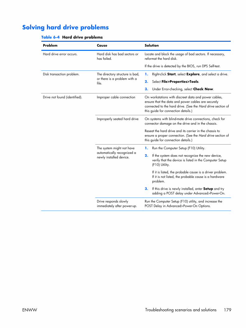
Solving hard drive problemsTable 6-4 Hard drive problems
Problem Cause Solution
Hard drive error occurs. Hard disk has bad sectors orhas failed.
Locate and block the usage of bad sectors. If necessary,reformat the hard disk.
If the drive is detected by the BIOS, run DPS Self-test.
Disk transaction problem. The directory structure is bad,or there is a problem with afile.
1. Right-click Start, select Explore, and select a drive.
2. Select File>Properties>Tools.
3. Under Error-checking, select Check Now.
Drive not found (identified). Improper cable connection On workstations with discreet data and power cables,ensure that the data and power cables are securelyconnected to the hard drive. (See the Hard drive section ofthis guide for connection details.)
Improperly seated hard drive On systems with blind-mate drive connections, check forconnector damage on the drive and in the chassis.
Reseat the hard drive and its carrier in the chassis toensure a proper connection. (See the Hard drive section ofthis guide for connection details.)
The system might not haveautomatically recognized anewly installed device.
1. Run the Computer Setup (F10) Utility.
2. If the system does not recognize the new device,verify that the device is listed in the Computer Setup(F10) Utility.
If it is listed, the probable cause is a driver problem.If it is not listed, the probable cause is a hardwareproblem.
3. If this drive is newly installed, enter Setup and tryadding a POST delay under Advanced>Power-On.
Drive responds slowlyimmediately after power-up.
Run the Computer Setup (F10) utility, and increase thePOST Delay in Advanced>Power-On Options.
ENWW Troubleshooting scenarios and solutions 179
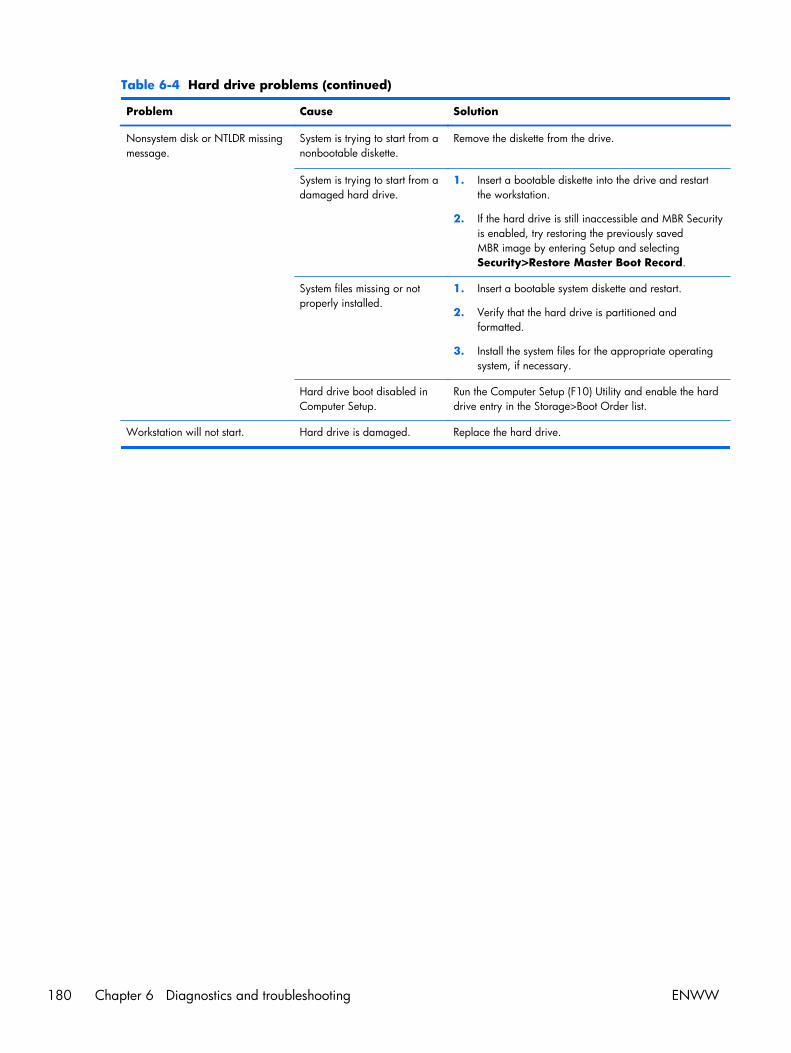
Table 6-4 Hard drive problems (continued)
Problem Cause Solution
Nonsystem disk or NTLDR missingmessage.
System is trying to start from anonbootable diskette.
Remove the diskette from the drive.
System is trying to start from adamaged hard drive.
1. Insert a bootable diskette into the drive and restartthe workstation.
2. If the hard drive is still inaccessible and MBR Securityis enabled, try restoring the previously savedMBR image by entering Setup and selectingSecurity>Restore Master Boot Record.
System files missing or notproperly installed.
1. Insert a bootable system diskette and restart.
2. Verify that the hard drive is partitioned andformatted.
3. Install the system files for the appropriate operatingsystem, if necessary.
Hard drive boot disabled inComputer Setup.
Run the Computer Setup (F10) Utility and enable the harddrive entry in the Storage>Boot Order list.
Workstation will not start. Hard drive is damaged. Replace the hard drive.
180 Chapter 6 Diagnostics and troubleshooting ENWW
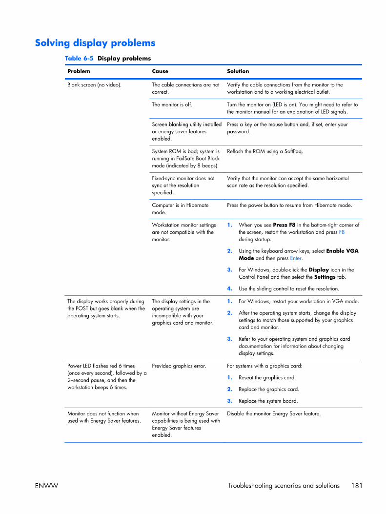
Solving display problemsTable 6-5 Display problems
Problem Cause Solution
Blank screen (no video). The cable connections are notcorrect.
Verify the cable connections from the monitor to theworkstation and to a working electrical outlet.
The monitor is off. Turn the monitor on (LED is on). You might need to refer tothe monitor manual for an explanation of LED signals.
Screen blanking utility installedor energy saver featuresenabled.
Press a key or the mouse button and, if set, enter yourpassword.
System ROM is bad; system isrunning in FailSafe Boot Blockmode (indicated by 8 beeps).
Reflash the ROM using a SoftPaq.
Fixed-sync monitor does notsync at the resolutionspecified.
Verify that the monitor can accept the same horizontalscan rate as the resolution specified.
Computer is in Hibernatemode.
Press the power button to resume from Hibernate mode.
Workstation monitor settingsare not compatible with themonitor.
1. When you see Press F8 in the bottom-right corner ofthe screen, restart the workstation and press F8during startup.
2. Using the keyboard arrow keys, select Enable VGAMode and then press Enter.
3. For Windows, double-click the Display icon in theControl Panel and then select the Settings tab.
4. Use the sliding control to reset the resolution.
The display works properly duringthe POST but goes blank when theoperating system starts.
The display settings in theoperating system areincompatible with yourgraphics card and monitor.
1. For Windows, restart your workstation in VGA mode.
2. After the operating system starts, change the displaysettings to match those supported by your graphicscard and monitor.
3. Refer to your operating system and graphics carddocumentation for information about changingdisplay settings.
Power LED flashes red 6 times(once every second), followed by a2–second pause, and then theworkstation beeps 6 times.
Prevideo graphics error. For systems with a graphics card:
1. Reseat the graphics card.
2. Replace the graphics card.
3. Replace the system board.
Monitor does not function whenused with Energy Saver features.
Monitor without Energy Savercapabilities is being used withEnergy Saver featuresenabled.
Disable the monitor Energy Saver feature.
ENWW Troubleshooting scenarios and solutions 181
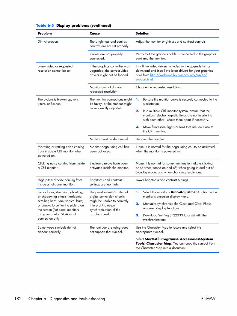
Table 6-5 Display problems (continued)
Problem Cause Solution
Dim characters The brightness and contrastcontrols are not set properly.
Adjust the monitor brightness and contrast controls.
Cables are not properlyconnected.
Verify that the graphics cable is connected to the graphicscard and the monitor.
Blurry video or requestedresolution cannot be set.
If the graphics controller wasupgraded, the correct videodrivers might not be loaded.
Install the video drivers included in the upgrade kit, ordownload and install the latest drivers for your graphicscard from http://welcome.hp.com/country/us/en/support.html.
Monitor cannot displayrequested resolution.
Change the requested resolution.
The picture is broken up, rolls,jitters, or flashes.
The monitor connections mightbe faulty, or the monitor mightbe incorrectly adjusted.
1. Be sure the monitor cable is securely connected to theworkstation.
2. In a multiple CRT monitor system, ensure that themonitors' electromagnetic fields are not interferingwith each other . Move them apart if necessary.
3. Move fluorescent lights or fans that are too close tothe CRT monitor.
Monitor must be degaussed. Degauss the monitor.
Vibrating or rattling noise comingfrom inside a CRT monitor whenpowered on.
Monitor degaussing coil hasbeen activated.
None. It is normal for the degaussing coil to be activatedwhen the monitor is powered on.
Clicking noise coming from insidea CRT monitor.
Electronic relays have beenactivated inside the monitor.
None. It is normal for some monitors to make a clickingnoise when turned on and off, when going in and out ofStandby mode, and when changing resolutions.
High pitched noise coming frominside a flat-panel monitor.
Brightness and contrastsettings are too high.
Lower brightness and contrast settings.
Fuzzy focus; streaking, ghosting,or shadowing effects; horizontalscrolling lines; faint vertical bars;or unable to center the picture onthe screen (flat-panel monitorsusing an analog VGA inputconnection only.)
Flat-panel monitor’s internaldigital conversion circuitsmight be unable to correctlyinterpret the outputsynchronization of thegraphics card.
1. Select the monitor’s Auto-Adjustment option in themonitor’s onscreen display menu.
2. Manually synchronize the Clock and Clock Phaseonscreen display functions.
3. Download SoftPaq SP22333 to assist with thesynchronization).
Some typed symbols do notappear correctly.
The font you are using doesnot support that symbol.
Use the Character Map to locate and select theappropriate symbol.
Select Start>All Programs> Accessories>SystemTools>Character Map. You can copy the symbol fromthe Character Map into a document.
182 Chapter 6 Diagnostics and troubleshooting ENWW
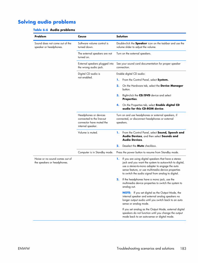
Solving audio problemsTable 6-6 Audio problems
Problem Cause Solution
Sound does not come out of thespeaker or headphones.
Software volume control isturned down.
Double-click the Speaker icon on the taskbar and use thevolume slider to adjust the volume.
The external speakers are notturned on.
Turn on the external speakers.
External speakers plugged intothe wrong audio jack.
See your sound card documentation for proper speakerconnection.
Digital CD audio isnot enabled.
Enable digital CD audio:
1. From the Control Panel, select System.
2. On the Hardware tab, select the Device Managerbutton.
3. Right-click the CD/DVD device and selectProperties.
4. On the Properties tab, select Enable digital CDaudio for this CD-ROM device.
Headphones or devicesconnected to the line-outconnector have muted theinternal speaker.
Turn on and use headphones or external speakers, ifconnected, or disconnect headphones or externalspeakers.
Volume is muted. 1. From the Control Panel, select Sound, Speech andAudio Devices, and then select Sounds andAudio Devices.
2. Deselect the Mute checkbox.
Computer is in Standby mode. Press the power button to resume from Standby mode.
Noise or no sound comes out ofthe speakers or headphones.
1. If you are using digital speakers that have a stereojack and you want the system to autoswitch to digital,use a stereo-to-mono adapter to engage the autosense feature, or use multimedia device propertiesto switch the audio signal from analog to digital.
2. If the headphones have a mono jack, use themultimedia device properties to switch the system toanalog out.
NOTE: If you set digital as the Output Mode, theinternal speaker and external analog speakers nolonger output audio until you switch back to an autosense or analog mode.
If you set analog as the Output Mode, external digitalspeakers do not function until you change the outputmode back to an auto-sense or digital mode.
ENWW Troubleshooting scenarios and solutions 183
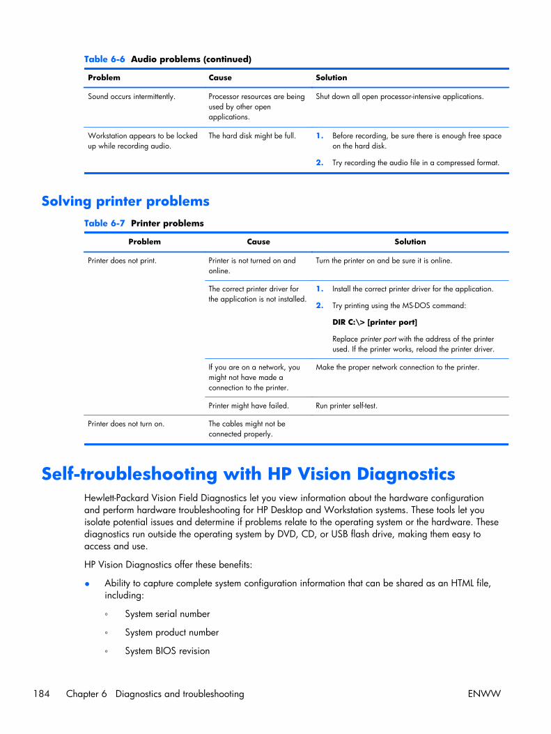
Table 6-6 Audio problems (continued)
Problem Cause Solution
Sound occurs intermittently. Processor resources are beingused by other openapplications.
Shut down all open processor-intensive applications.
Workstation appears to be lockedup while recording audio.
The hard disk might be full. 1. Before recording, be sure there is enough free spaceon the hard disk.
2. Try recording the audio file in a compressed format.
Solving printer problemsTable 6-7 Printer problems
Problem Cause Solution
Printer does not print. Printer is not turned on andonline.
Turn the printer on and be sure it is online.
The correct printer driver forthe application is not installed.
1. Install the correct printer driver for the application.
2. Try printing using the MS-DOS command:
DIR C:\> [printer port]
Replace printer port with the address of the printerused. If the printer works, reload the printer driver.
If you are on a network, youmight not have made aconnection to the printer.
Make the proper network connection to the printer.
Printer might have failed. Run printer self-test.
Printer does not turn on. The cables might not beconnected properly.
Self-troubleshooting with HP Vision DiagnosticsHewlett-Packard Vision Field Diagnostics let you view information about the hardware configurationand perform hardware troubleshooting for HP Desktop and Workstation systems. These tools let youisolate potential issues and determine if problems relate to the operating system or the hardware. Thesediagnostics run outside the operating system by DVD, CD, or USB flash drive, making them easy toaccess and use.
HP Vision Diagnostics offer these benefits:
● Ability to capture complete system configuration information that can be shared as an HTML file,including:
◦ System serial number
◦ System product number
◦ System BIOS revision
184 Chapter 6 Diagnostics and troubleshooting ENWW

◦ Memory size and configuration
◦ Processor information
◦ Storage device information and configuration
◦ Graphics / audio / communications information and configuration
◦ And more...
● Comprehensive list of diagnostic test available with new added features:
◦ Highly configurable testing options: quick / complete / custom / interactive / non-interactive
◦ Specific failing memory DIMM identification
◦ Tests video card memory
◦ Launches DST Smart tests for both SATA and SAS drives
◦ Many other tests and diagnostics
● Diagnostic Failure Code Output – A unique warranty code is generated for each failure which canbe used to validate diagnostic use for a specific system
● Easy to use - uses similar user interface as previous field diagnostics, HP Insight Diagnostics
● True End2End diagnostics – same diagnostics modules used in factory
● Easy to obtain:
◦ Download from Web
◦ Bootable via USB flash drive, DVD, or CD
◦ Included with restore media
Please run Vision diagnostics on supported products when attempting to troubleshoot system issues.
OverviewThe HP Vision Diagnostics utility lets you view information about the hardware configuration of theworkstation and perform hardware diagnostic tests on subsystems. The utility simplifies the process ofeffectively identifying, diagnosing, and isolating hardware issues.
Invoke HP Vision Diagnostics to display the Survey tab. This tab shows the current configuration of theworkstation. From the Survey tab, you can access several categories of information about theworkstation. Other tabs provide additional information, including diagnostic test options and testresults.
Use HP Vision Diagnostics to determine if the system recognizes all the devices installed on theworkstation and if the devices function properly. HP recommends that you run these tests after youinstall or connect new devices.
You can save the information from each diagnostic screen to an HTML file. You should run tests, savethe test results, and print them so that you have a report available before placing a call to the CustomerSupport Center.
NOTE: HP Vision Diagnostics may not detect third-party devices..
ENWW Self-troubleshooting with HP Vision Diagnostics 185

Downloading and accessing HP Vision DiagnosticsFollow these steps to download the HP Vision Diagnostics utility from the HP Web site to a CD, DVD, orUSB flash drive. Then use the disk or drive to perform diagnostics on the workstation:
1. Go to http://www.hp.com.
2. Select the Support & Drivers link.
3. Select the Download driver and software radio button.
4. Enter your product number in the text box, and then press Enter.
5. Select your operating system.
6. Select the Diagnostic link.
7. Locate HP Vision Diagnostics and select Download.
8. After the .iso file is downloaded, save the file to a USB flash drive (recommended for fasterperformance) or use CD-ROM burning software to copy the .iso file to an optical medium.
9. Insert the disk or USB drive into the workstation while it is turned on.
10. Shut down the workstation.
11. Turn on the workstation. The system boots into HP Vision Diagnostics.
NOTE: If the system does not boot to the CD in the optical drive or the USB flash drive, you mayneed to change the boot order. You may use the Computer Setup (F10) utility to change the bootorder, or press F9 to select the appropriate boot device.
12. At the boot menu, select either the HP Vision Diagnostics utility to test the various hardwarecomponents in the computer or the HP Memory Test utility to test memory only.
NOTE: The HP Memory Test, a comprehensive memory diagnostic utility, runs as a stand-aloneapplication, outside of HP Vision Diagnostics.
If the workstation boots from a CD, you must use a separate boot CD to run the memorydiagnostic. Hence, HP recommends that you use a USB key to boot the diagnostic utilities. It isfaster than using a CD or DVD, and it accommodates both Memory and Vision diagnostics.
13. If you run HP Vision Diagnostics, select the appropriate language and click Continue.
14. In the End User License Agreement page, select Agree if you agree with the terms. The HP VisionDiagnostics utility launches and displays the Survey tab.
186 Chapter 6 Diagnostics and troubleshooting ENWW

Accessing HP Vision Diagnostics on the workstationThe following procedures describe how to access the HP Vision Diagnostics utilities included in theworkstation software.
Creating and using a bootable USB key
This section describes how to use a USB key to access the HP Vision Diagnostics.
NOTE: Using a USB key is the most convenient method to access the HP Vision Diagnostics.
1. In the C:\VisionDiagnostics\ directory, double-click on VisionDiagUSB.exe. A setup menuappears.
2. Follow the setup prompts to create a bootable ISO image of the diagnostic utilities on a USB key.
3. Use the operating system to turn off the workstation.
4. Restart the workstation with the USB key installed. The workstation boots to the USB key andinitiates HP Vision Diagnostics.
5. Follow the prompts to troubleshoot the workstation.
Creating and using a bootable DVD
This section describes how to use a DVD to access the HP Vision Diagnostics.
1. In the C:\VisionDiagnostics\ directory, double-click on the VisionDiagISO.exe file. A setup menuappears.
2. Follow the setup prompts to create a bootable ISO image of the diagnostic utilities on a DVD.
3. Enable a workstation boot from DVD.
4. Use the operating system to turn off the workstation.
5. Restart the workstation with the with the DVD installed in the optical drive. The workstation boots tothe DVD and initiates HP Vision Diagnostics.
6. Follow the HP Vision Field Diagnostic prompts to troubleshoot the workstation.
Using the HP Memory Test utility
This section describes how to access the HP Memory Test utility.
NOTE: The HP Memory Test is a comprehensive memory diagnostic utility that is run as a stand-aloneapplication, outside of HP Vision Diagnostics.
If the workstation is booted from a CD, a separate boot CD will be required to use the memorydiagnostic. Hence, HP recommends that a USB key be used to boot the diagnostic utilities. It is fasterthan using a CD, and it accommodates both Memory and Vision diagnostics.
1. In the C:\VisionDiagnostics\ directory, double-click on the MemoryDiagISO.exe file. A setupmenu appears.
2. Follow the setup prompts to create a bootable ISO image of the memory diagnostic utility on aDVD.
3. Use the operating system to turn off the workstation.
ENWW Self-troubleshooting with HP Vision Diagnostics 187

4. Restart the workstation with the with the DVD installed in the optical drive. The workstation boots tothe DVD and initiates the memory diagnostic utility.
5. Follow the diagnostic prompts to troubleshoot workstation memory.
188 Chapter 6 Diagnostics and troubleshooting ENWW
User interfaceThe HP Vision Diagnostics application provides six major functions, accessible through Tabs. Thesefunctions are:
● Survey — Your current system hardware information.
● Test — List all diagnostics available for your system. Tests are started there.
● Status — This screen shows progress and status of currently running diagnostics.
● History — All past diagnostics runs and status are listed there.
● Errors — All past diagnostics failures are listed there.
● Help — User help about HP Vision Diagnostics.
There are also some common operations that are part of the utility. They include:
● Exit Diagnostics button — This button will close HP Vision Diagnostic application and rebootyour system. Any running test will be aborted.
● Reload button — If available, this button will rescan your system hardware and reload thediagnostics without the need to restart your entire system.
● Save button — If available, save your system survey, test history or error data as an HTML file toa floppy disk or a USB key drive.
Survey tab
The Survey tab shows your system hardware information, organized into eleven Categories (forexample "Processors") and device instances (for example "Processor 1").
The amount of information displayed can be controlled by selecting a combination of View Level andCategory.
The View Levels include:
● Overview — shows high level summary of the system hardware. This is the default view level.
● Summary — gives limited configuration data for each specific Category.
● Advanced — offers more technical and low-level data for the computer-savvy user.
The Categories Levels include:
● All — Shows all Categories.
● Architecture — Shows system architecture information such as high level PCI devices, low levelSMBIOS, CMOS and PCI configuration space data.
● Audio — Shows all embedded and add-on audio devices.
● Asset Control — Shows asset control related information such as product name, serial number,asset tag, and universal unique ID information.
● Communication — Shows communication devices such as serial, parallel, USB, network,Firewire, modem, and Bluetooth ports and devices.
● Graphics — Shows all embedded and add-on video cards.
ENWW Self-troubleshooting with HP Vision Diagnostics 189

● Input Devices — Shows user input devices such as all connected mice and keyboards.
● Memory — Shows system memory information.
● Miscellaneous — List any devices or data that don't belong to any other Category.
● Processors - Shows system processors.
● Storage — Shows mass storage devices such as floppy drives, optical drives, SATA, SAS harddisk drives and controllers, as well as any RAID arrays.
● System — Shows information about system board devices such as fans and cables.
190 Chapter 6 Diagnostics and troubleshooting ENWW

Test tab
The Test tab lists all available diagnostics. The lists have been tailored according to your systemconfiguration. You can select or unselect different Test Modes:
● Quick — Performs quick-performance tests that cover your entire hardware. You cannot changetest parameters.
● Complete — Performs all available tests but may take a long time to complete. You cannotchange test parameters.
● Custom — Offers all available tests, and you can change test parameters to fit your specificneeds. For advanced users only!
By default, the three test modes do not display prompts and require no interaction. Errors are displayedwhen testing is complete.
To add interactive tests, click the Include interactive tests box under Test Mode. Interactive testsgive you maximum control over the testing process. The diagnostic software prompts you for inputduring tests.
NOTE: Memory can not be tested from within the HP Vision Diagnostics application. To test thememory in your workstation, exit HP Vision Field Diagnostic, boot to either the CD or USB flash driveand select HP Memory Test from the boot menu.
The Duration of Test options control the duration of the test sequence. The following options areavailable:
● Number of loops — A test selection will run once by default. Enter a positive number to makea test selection run many times.
● Total test time (hours:minutes) — Alternatively, the test selection can be set to run for aspecified amount of time. This does not guarantee that all tests will run if the entered time is lessthan the necessary time to run all the tests
● Stop at first error— Check this option to stop test execution as soon as one error isencountered.
The following Test Controls exist:
● Select All, Unselect All button — This button toggles to select or unselect all the tests from thetest selection tree.
● Expand, Collapse button — This button toggles to expand or collapse the test selection tree.
● Start Test button — Click this button to start executing all selected tests. HP Vision Diagnosticswill automatically switch to the Status tab in order to keep track of the test execution and status.
WARNING! Once started, do not reboot or power off your computer until all the tests have beencompleted.
To begin testing:
1. Select the Test tab.
2. Select the type of tests you want to run: Quick, Complete, or Custom.
3. Include optional interactive tests by selecting Include interactive tests.
ENWW Self-troubleshooting with HP Vision Diagnostics 191

4. Choose how you want the test to be executed, either Number of Loops or Total Test Time.When choosing to run the test over a specified number of loops, enter the number of loops toperform. If you want the diagnostic test for a specified time period, enter the amount of time inminutes.
5. Click the Start Test button to begin the testing. This displays the Status tab, which lets youmonitor the progress of the tests. When the tests finish, the Status tab shows whether the devicespassed or failed.
6. If errors are found, go to the Errors tab to display detailed information and recommended actions.
192 Chapter 6 Diagnostics and troubleshooting ENWW

Status tab
The Status tab shows the overall progress and status of the test scenario as well as the progress andstatus of each test. The color coded status are black, blue, green, red, and orange.
The Status tab colors are:
● Waiting (black) — when no test is running
● Running (blue) — when at least one test is currently running
● Passed (green) — when all tests have run successfully, meaning that no hardware error or defecthas been detected
● Failed (red) — when thee tests have detected at least one error with your system
● Canceled (orange) — when the test scenario has been explicitly canceled, in which case no passor fail conclusion can be drawn
The available data is:
● Current Loop — Shows the current execution loop out of total number of loops specified in theTest panel.
● Test Time — Shows the total time elapsed since the beginning of the test execution.
● Test Complete — Shows the number of tests successfully completed out of the total number oftest to execute.
● Cancel button — Push the Cancel button to immediately terminate all currently running tests.
History tab
The History tab shows the history of the past test executions.
The History Log displays all tests that have been executed, the number of times of execution, the numberof times failed, the date each test was executed, and the time it took to complete each test. The ClearHistory button will clear the contents of the History Log.
The contents of the History Log may be saved as a HTML file to either floppy or USB flash drive byclicking the Save button.
Errors tab
The Errors tab displays detailed information about any errors found, as well as any recommendedactions.
The Error Log displays the tests for devices that have failed during the diagnostic testing and includesthe following columns of information.
● The Device section displays the device tested.
● The Test section displays the type of test run.
● The Times Failed is the number of times the device has failed a test.
● The Defect Code provides a numerical code for the failure. The error codes are defined in theHelp tab.
● The Description section describes the error that the diagnostic test found.
ENWW Self-troubleshooting with HP Vision Diagnostics 193

● The Reason section describes the likely cause of the error.
● The Recommended Repair will give a recommended action that should be performed to resolve thefailed hardware.
● The Warranty ID is a unique error code associated with the specific error on your computer.When contacting the HP Support Center for assistance with a hardware failure, please beprepared to provide the Warranty ID.
● The Clear Errors button will clear the contents of the Error Log.
The contents of the Error Log may be saved as a HTML file to either floppy or USB flash drive byclicking the Save button.
Help tab
The Help tab contains a Vision Help section, and a Test Components section. This tab includes searchand index features. You may also review the HP End User License Agreement (EULA), as well as the HPVision Field Diagnostic application version information on this tab.
The various sections located here are:
● The Vision Help section contains information on the major functions of HP Vision Diagnostics.
● The Test components section provides a description of each test, as well as the parameters thatmay be adjusted when running in Custom test mode.
● The Defect codes section contains information on the numerical error code that may appear in theErrors tab.
● The Memory test tab section provides information on the HP Memory Test application that may belaunched from the boot menu.
● The HP Support section provides information on obtaining technical support from HP.
194 Chapter 6 Diagnostics and troubleshooting ENWW

Saving and printing information in HP Vision DiagnosticsYou can save the information displayed in the HP Vision Diagnostics Survey, History and Errors tabs toa diskette or a USB flash drive. You can not save to the hard drive. The system will automatically createan html file that has the same appearance as the information displayed on the screen.
1. Insert a diskette or USB flash drive if running HP Vision Diagnostics from CD.
2. Click Save in the bottom on any of the Survey, History or Errors tabs. All three log files will besaved regardless of from which tab the Save button was clicked.
3. Select the drive onto which you will save the log files and click the Save button. Three html fileswill be saved to the inserted diskette or USB flash drive.
NOTE: Do not remove the diskette or USB key until you see a message indicating that the htmlfiles have been written to the media.
4. Print the desired information from the storage device used to save it.
NOTE: To exit HP Vision Diagnostics, click the Exit Diagnostics button at the bottom of thescreen. Be sure to remove the USB flash drive or CD from the optical drive.
Diagnostic codes and errorsThis section presents information about diagnostic LED codes, LED color definitions, and POST errormessages to help you troubleshoot problems.
Diagnostic LED and audible (beep) codesThis section describes the front and rear panel LED error and operation codes as well as the audiblecodes that might occur before or during the POST.
NOTE: Some workstation models do not have Built-In Self Test (BIST) LED functionality.
ENWW Diagnostic codes and errors 195
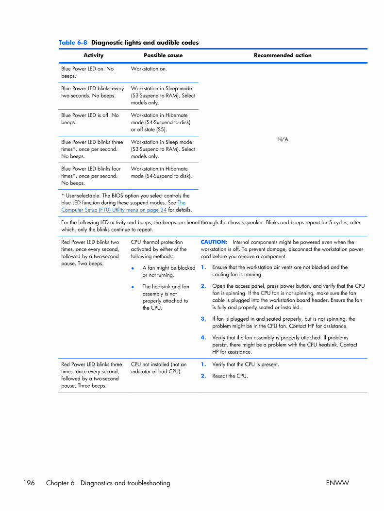
Table 6-8 Diagnostic lights and audible codes
Activity Possible cause Recommended action
Blue Power LED on. Nobeeps.
Workstation on.
N/A
Blue Power LED blinks everytwo seconds. No beeps.
Workstation in Sleep mode(S3-Suspend to RAM). Selectmodels only.
Blue Power LED is off. Nobeeps.
Workstation in Hibernatemode (S4-Suspend to disk)or off state (S5).
Blue Power LED blinks threetimes*, once per second.No beeps.
Workstation in Sleep mode(S3-Suspend to RAM). Selectmodels only.
Blue Power LED blinks fourtimes*, once per second.No beeps.
Workstation in Hibernatemode (S4-Suspend to disk).
* User-selectable. The BIOS option you select controls theblue LED function during these suspend modes. See TheComputer Setup (F10) Utility menu on page 34 for details.
For the following LED activity and beeps, the beeps are heard through the chassis speaker. Blinks and beeps repeat for 5 cycles, afterwhich, only the blinks continue to repeat.
Red Power LED blinks twotimes, once every second,followed by a two-secondpause. Two beeps.
CPU thermal protectionactivated by either of thefollowing methods:
● A fan might be blockedor not turning.
● The heatsink and fanassembly is notproperly attached tothe CPU.
CAUTION: Internal components might be powered even when theworkstation is off. To prevent damage, disconnect the workstation powercord before you remove a component.
1. Ensure that the workstation air vents are not blocked and thecooling fan is running.
2. Open the access panel, press power button, and verify that the CPUfan is spinning. If the CPU fan is not spinning, make sure the fancable is plugged into the workstation board header. Ensure the fanis fully and properly seated or installed.
3. If fan is plugged in and seated properly, but is not spinning, theproblem might be in the CPU fan. Contact HP for assistance.
4. Verify that the fan assembly is properly attached. If problemspersist, there might be a problem with the CPU heatsink. ContactHP for assistance.
Red Power LED blinks threetimes, once every second,followed by a two-secondpause. Three beeps.
CPU not installed (not anindicator of bad CPU).
1. Verify that the CPU is present.
2. Reseat the CPU.
196 Chapter 6 Diagnostics and troubleshooting ENWW
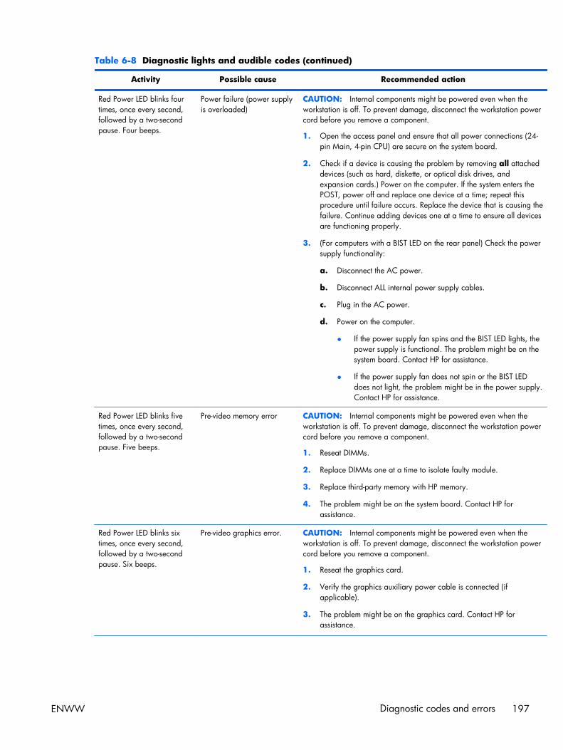
Table 6-8 Diagnostic lights and audible codes (continued)
Activity Possible cause Recommended action
Red Power LED blinks fourtimes, once every second,followed by a two-secondpause. Four beeps.
Power failure (power supplyis overloaded)
CAUTION: Internal components might be powered even when theworkstation is off. To prevent damage, disconnect the workstation powercord before you remove a component.
1. Open the access panel and ensure that all power connections (24-pin Main, 4-pin CPU) are secure on the system board.
2. Check if a device is causing the problem by removing all attacheddevices (such as hard, diskette, or optical disk drives, andexpansion cards.) Power on the computer. If the system enters thePOST, power off and replace one device at a time; repeat thisprocedure until failure occurs. Replace the device that is causing thefailure. Continue adding devices one at a time to ensure all devicesare functioning properly.
3. (For computers with a BIST LED on the rear panel) Check the powersupply functionality:
a. Disconnect the AC power.
b. Disconnect ALL internal power supply cables.
c. Plug in the AC power.
d. Power on the computer.
● If the power supply fan spins and the BIST LED lights, thepower supply is functional. The problem might be on thesystem board. Contact HP for assistance.
● If the power supply fan does not spin or the BIST LEDdoes not light, the problem might be in the power supply.Contact HP for assistance.
Red Power LED blinks fivetimes, once every second,followed by a two-secondpause. Five beeps.
Pre-video memory error CAUTION: Internal components might be powered even when theworkstation is off. To prevent damage, disconnect the workstation powercord before you remove a component.
1. Reseat DIMMs.
2. Replace DIMMs one at a time to isolate faulty module.
3. Replace third-party memory with HP memory.
4. The problem might be on the system board. Contact HP forassistance.
Red Power LED blinks sixtimes, once every second,followed by a two-secondpause. Six beeps.
Pre-video graphics error. CAUTION: Internal components might be powered even when theworkstation is off. To prevent damage, disconnect the workstation powercord before you remove a component.
1. Reseat the graphics card.
2. Verify the graphics auxiliary power cable is connected (ifapplicable).
3. The problem might be on the graphics card. Contact HP forassistance.
ENWW Diagnostic codes and errors 197
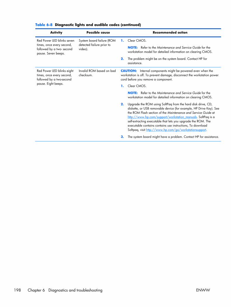
Table 6-8 Diagnostic lights and audible codes (continued)
Activity Possible cause Recommended action
Red Power LED blinks seventimes, once every second,followed by a two- secondpause. Seven beeps.
System board failure (ROMdetected failure prior tovideo).
1. Clear CMOS.
NOTE: Refer to the Maintenance and Service Guide for theworkstation model for detailed information on clearing CMOS.
2. The problem might be on the system board. Contact HP forassistance.
Red Power LED blinks eighttimes, once every second,followed by a two-secondpause. Eight beeps.
Invalid ROM based on badchecksum.
CAUTION: Internal components might be powered even when theworkstation is off. To prevent damage, disconnect the workstation powercord before you remove a component.
1. Clear CMOS.
NOTE: Refer to the Maintenance and Service Guide for theworkstation model for detailed information on clearing CMOS.
2. Upgrade the ROM using SoftPaq from the hard disk drive, CD,diskette, or USB removable device (for example, HP Drive Key). Seethe ROM Flash section of the Maintenance and Service Guide athttp://www.hp.com/support/workstation_manuals. SoftPaq is aself-extracting executable that lets you upgrade the ROM. Theexecutable contains contains use instructions, To downloadSoftpaq, visit http://www.hp.com/go/workstationsupport.
3. The system board might have a problem. Contact HP for assistance.
198 Chapter 6 Diagnostics and troubleshooting ENWW
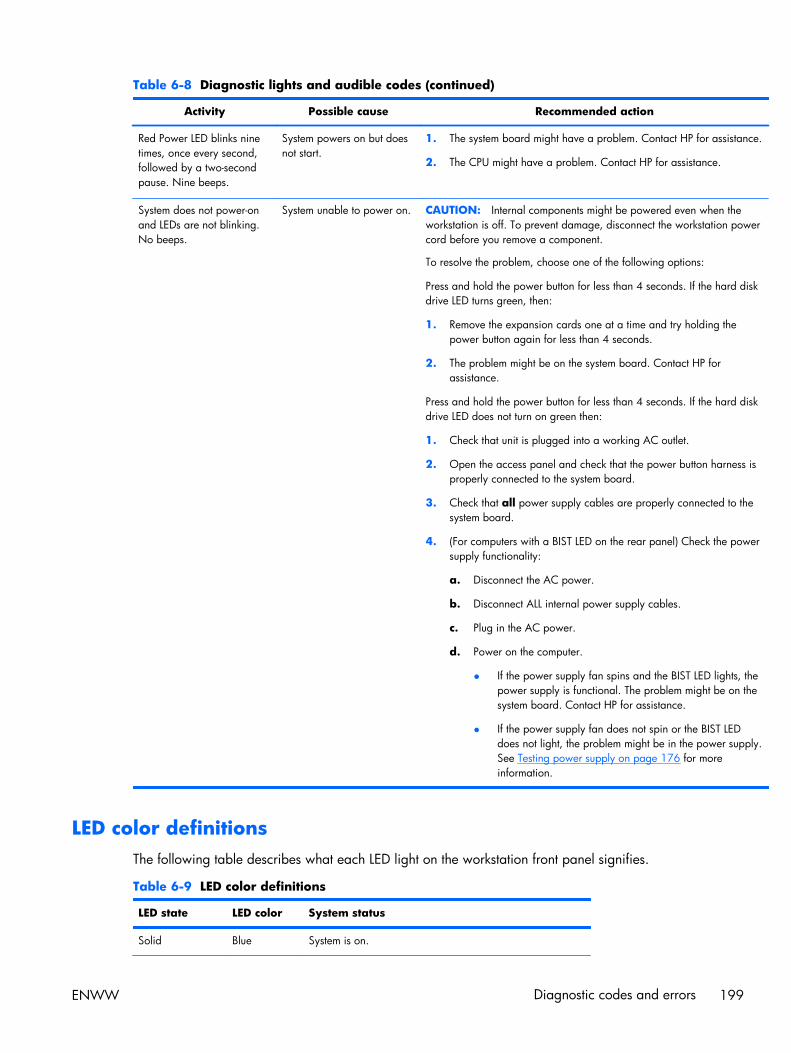
Table 6-8 Diagnostic lights and audible codes (continued)
Activity Possible cause Recommended action
Red Power LED blinks ninetimes, once every second,followed by a two-secondpause. Nine beeps.
System powers on but doesnot start.
1. The system board might have a problem. Contact HP for assistance.
2. The CPU might have a problem. Contact HP for assistance.
System does not power-onand LEDs are not blinking.No beeps.
System unable to power on. CAUTION: Internal components might be powered even when theworkstation is off. To prevent damage, disconnect the workstation powercord before you remove a component.
To resolve the problem, choose one of the following options:
Press and hold the power button for less than 4 seconds. If the hard diskdrive LED turns green, then:
1. Remove the expansion cards one at a time and try holding thepower button again for less than 4 seconds.
2. The problem might be on the system board. Contact HP forassistance.
Press and hold the power button for less than 4 seconds. If the hard diskdrive LED does not turn on green then:
1. Check that unit is plugged into a working AC outlet.
2. Open the access panel and check that the power button harness isproperly connected to the system board.
3. Check that all power supply cables are properly connected to thesystem board.
4. (For computers with a BIST LED on the rear panel) Check the powersupply functionality:
a. Disconnect the AC power.
b. Disconnect ALL internal power supply cables.
c. Plug in the AC power.
d. Power on the computer.
● If the power supply fan spins and the BIST LED lights, thepower supply is functional. The problem might be on thesystem board. Contact HP for assistance.
● If the power supply fan does not spin or the BIST LEDdoes not light, the problem might be in the power supply.See Testing power supply on page 176 for moreinformation.
LED color definitionsThe following table describes what each LED light on the workstation front panel signifies.
Table 6-9 LED color definitions
LED state LED color System status
Solid Blue System is on.
ENWW Diagnostic codes and errors 199

Table 6-9 LED color definitions (continued)
LED state LED color System status
Flashing Blue System is in Standby.
Solid or flashing Red System has experienced an error. (See POST errormessages on page 201.)
None No light System is in Hibernate, or is off.
200 Chapter 6 Diagnostics and troubleshooting ENWW
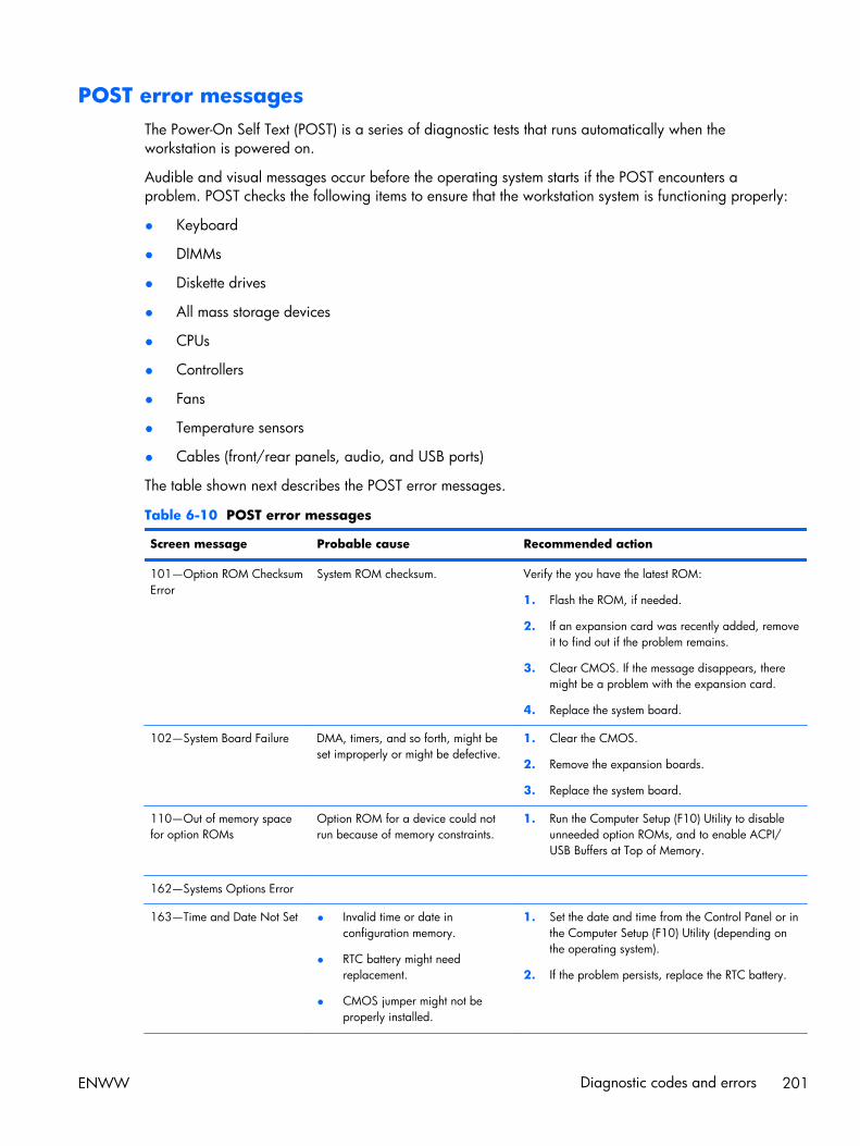
POST error messagesThe Power-On Self Text (POST) is a series of diagnostic tests that runs automatically when theworkstation is powered on.
Audible and visual messages occur before the operating system starts if the POST encounters aproblem. POST checks the following items to ensure that the workstation system is functioning properly:
● Keyboard
● DIMMs
● Diskette drives
● All mass storage devices
● CPUs
● Controllers
● Fans
● Temperature sensors
● Cables (front/rear panels, audio, and USB ports)
The table shown next describes the POST error messages.
Table 6-10 POST error messages
Screen message Probable cause Recommended action
101—Option ROM ChecksumError
System ROM checksum. Verify the you have the latest ROM:
1. Flash the ROM, if needed.
2. If an expansion card was recently added, removeit to find out if the problem remains.
3. Clear CMOS. If the message disappears, theremight be a problem with the expansion card.
4. Replace the system board.
102—System Board Failure DMA, timers, and so forth, might beset improperly or might be defective.
1. Clear the CMOS.
2. Remove the expansion boards.
3. Replace the system board.
110—Out of memory spacefor option ROMs
Option ROM for a device could notrun because of memory constraints.
1. Run the Computer Setup (F10) Utility to disableunneeded option ROMs, and to enable ACPI/USB Buffers at Top of Memory.
162—Systems Options Error
163—Time and Date Not Set ● Invalid time or date inconfiguration memory.
● RTC battery might needreplacement.
● CMOS jumper might not beproperly installed.
1. Set the date and time from the Control Panel or inthe Computer Setup (F10) Utility (depending onthe operating system).
2. If the problem persists, replace the RTC battery.
ENWW Diagnostic codes and errors 201

Table 6-10 POST error messages (continued)
Screen message Probable cause Recommended action
164—Memory Size Error Memory configuration is incorrect. 1. Run the Computer Setup (F10) Utility or theWindows utilities.
2. Verify that the memory modules are installedproperly.
3. If third-party memory has been added, test thememory configuration using HP memory.
4. Verify the memory module type.
201—Memory Error RAM failure. 1. Run the Computer Setup (F10) utility or theWindows utilities.
2. Be sure that memory modules are installedcorrectly.
3. Verify the memory module type.
4. Remove and replace memory modules one at atime to isolate faulty modules.
5. Replace faulty memory modules.
6. If the error persists after replacing memorymodules, replace the system board.
202—Memory Type Mismatch Memory modules do not match. Replace the memory modules with matched sets.
203—Memory module failedself-test and failing rank wasdisabled
Defective memory module. Replace the memory module.
204—Memory module failedand user rank was disabled
Improper module load. Reseat the memory module correctly.
205—Memory hightemperature detected
Insufficient memory module cooling. Verify that a memory module cooling fan is installedand operating.
206—Memory setup invalid Memory configured incorrectly. Reconfigure the memory modules in the proper slots.
207—Incompatible DIMMsdetected
DIMMs are installed that do not fulfillsystem requirements.
1. Verify that the memory module type matchesworkstation requirements.
2. Insert the DIMM in the proper memory socket.
3. Replace the DIMM if the problem persists.
208—Mismatched DIMMsdetected
Installed DIMMs are improperlymatched.
Verify that matching DIMMs are installed.
209—Memory warningcondition detected
Incorrect memory module type in use. Verify that the memory modules are compatible withworkstation requirements.
212—Failed Processor 0 Processor has failed to initialize. 1. Reseat the processor in its socket.
2. If the processor does not respond, replace it.
3. Replace the system board.
202 Chapter 6 Diagnostics and troubleshooting ENWW
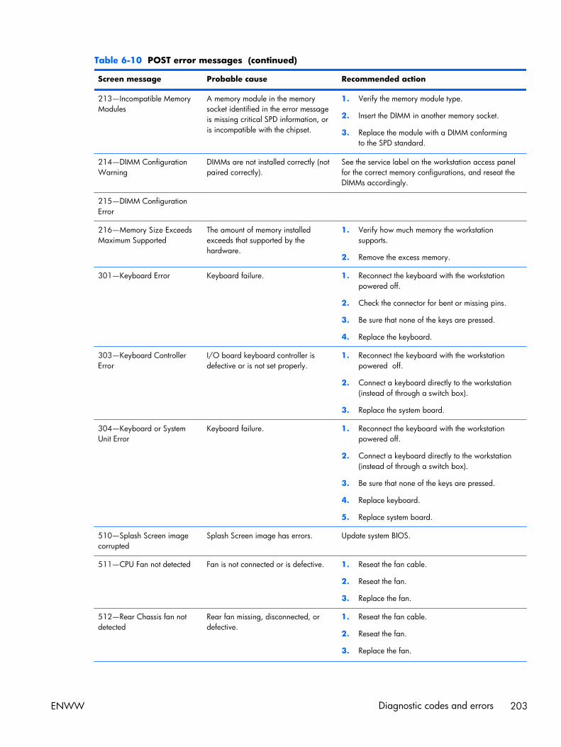
Table 6-10 POST error messages (continued)
Screen message Probable cause Recommended action
213—Incompatible MemoryModules
A memory module in the memorysocket identified in the error messageis missing critical SPD information, oris incompatible with the chipset.
1. Verify the memory module type.
2. Insert the DIMM in another memory socket.
3. Replace the module with a DIMM conformingto the SPD standard.
214—DIMM ConfigurationWarning
DIMMs are not installed correctly (notpaired correctly).
See the service label on the workstation access panelfor the correct memory configurations, and reseat theDIMMs accordingly.
215—DIMM ConfigurationError
216—Memory Size ExceedsMaximum Supported
The amount of memory installedexceeds that supported by thehardware.
1. Verify how much memory the workstationsupports.
2. Remove the excess memory.
301—Keyboard Error Keyboard failure. 1. Reconnect the keyboard with the workstationpowered off.
2. Check the connector for bent or missing pins.
3. Be sure that none of the keys are pressed.
4. Replace the keyboard.
303—Keyboard ControllerError
I/O board keyboard controller isdefective or is not set properly.
1. Reconnect the keyboard with the workstationpowered off.
2. Connect a keyboard directly to the workstation(instead of through a switch box).
3. Replace the system board.
304—Keyboard or SystemUnit Error
Keyboard failure. 1. Reconnect the keyboard with the workstationpowered off.
2. Connect a keyboard directly to the workstation(instead of through a switch box).
3. Be sure that none of the keys are pressed.
4. Replace keyboard.
5. Replace system board.
510—Splash Screen imagecorrupted
Splash Screen image has errors. Update system BIOS.
511—CPU Fan not detected Fan is not connected or is defective. 1. Reseat the fan cable.
2. Reseat the fan.
3. Replace the fan.
512—Rear Chassis fan notdetected
Rear fan missing, disconnected, ordefective.
1. Reseat the fan cable.
2. Reseat the fan.
3. Replace the fan.
ENWW Diagnostic codes and errors 203

Table 6-10 POST error messages (continued)
Screen message Probable cause Recommended action
513—Front Chassis fan notdetected
Front fan missing, disconnected, ordefective.
1. Reseat the fan cable.
2. Reseat the fan.
3. Replace the fan.
514—Memory fan notdetected
Memory fan missing, disconnected, ordefective.
1. Reseat the fan cable.
2. Reseat the fan.
3. Replace the fan.
515—CPU Overtempoccurred
Insufficient processor cooling orprocessor defect.
1. If necessary, add a heatsink to the processor andensure proper operation.
2. Replace the processor.
516—Chipset fan not detected Chipset fan missing, disconnected, ordefective.
1. Ensure that the fan is installed and connectedproperly.
2. Replace the fan.
517—Low power CPUheatsink(s) detected for highpower CPUs
Inadequate heatsink is installed. Replace the low power heatsink with a high powerheatsink.
518—Power supply wattageinsufficient for hardwareconfiguration
Workstation configuration requiresmore power than the power supplycan provide.
1. Reduce the workstation power consumption.
2. Replace the power supply with a high outputpower supply.
601—Diskette Controller Error Diskette controller circuitry or diskettedrive circuitry incorrect.
1. Run the Computer Setup (F10) utility.
2. Verify cabling and replace defective cables ifnecessary.
3. Clear CMOS.
4. Replace the diskette drive.
5. Replace the system board.
605—Diskette Drive TypeError
Mismatch in drive type. 1. Run the Computer Setup (F10) Utility.
2. Disconnect any other diskette controller devices(tape drives).
3. Clear the CMOS.
610—External Storage DeviceFailure
External storage device is notdetected, is improperly connected, oris defective.
1. Verify that the external device is present andconnected properly.
2. Replace the external device.
611—Primary Floppy PortAddress Assignment Conflict
The flexible disk drive is configured ata previously assigned address.
Select a new address for the flexible disk drive.
912—Computer Cover HasBeen Removed Since LastSystem Start Up
N/A No action required.
204 Chapter 6 Diagnostics and troubleshooting ENWW

Table 6-10 POST error messages (continued)
Screen message Probable cause Recommended action
914— Hood Lock Coil is notConnected
Mechanism is missing or is notconnected.
1. Reconnect or replace the missing mechanism.
2. Reseat or replace the missing mechanism cable.
916—Power Button NotConnected
Power button cable is disconnectedfrom the system board.
Reconnect the cable and restart.
917—Front Audio NotConnected
Front Audio mechanism is missing or isnot connected.
1. Replace or reconnect the missing front audiomechanism to the system board.
2. Reseat or replace the missing mechanism cable.
918—Front USB NotConnected
Front USB mechanism is missing or isnot connected.
1. Replace or reconnect the missing Front USBmechanism to the system board..
2. Reseat or replace the missing mechanism cable.
919—Multi-Bay Riser NotConnected
Multi-Bay riser mechanism is missingor is not connected.
1. Replace or reconnect the missing Multi-Baymechanism to the system board.
2. Reseat or replace the missing mechanism cable.
920—Fatal error on QPI link X Fatal error detected on QPI link x,where x is 0 or 1. This type of error isidentified on the line following theerror message.
Potential system board problem; contact HP Support.
921—Fatal error on QPIProtocol link X
Fatal error detected in QPI link xprotocol, where x is 0 or 1. This typeof error is identified on the linefollowing the error message.
Potential system board problem; contact HP Support.
922—Fatal error on PCIe slotX
Fatal error occurred in the designatedslot.
Move the card to a different slot. If the problempersists, replace the card.
923—Fatal error on ESI port 0 A fatal error occurred on ESI port 0.slot.
Verify that the ESI port device is connected andworking properly.
924—Fatal error on IOH coreX
Fatal error detected on IOH core x,where x is 0 or 1. This type of error isidentified on the line following.
Potential system board problem; contact HP Support.
925—Fatal error on IOHmiscellaneous
Fatal miscellaneous error detected onIOH core x, where x is 0 or 1.
Potential system board problem; contact HP Support.
926—Fatal error on IOH Vtd Fatal error detected in the IntelVirtualization Technology.
Potential system board problem; contact HP Support.
927—Fatal error on DIMM inslot CPU X DIMM Y
Fatal multibit ECC error detected onthe DIMM in the slot labeled CPU xDIMM y (where x is 0 or 1 and y is 1 -6), as labeled on the system board.
Replace the DIMM in the identified slot.
928—Fatal machine checkdetected on CPU X
Contact HP support.
ENWW Diagnostic codes and errors 205
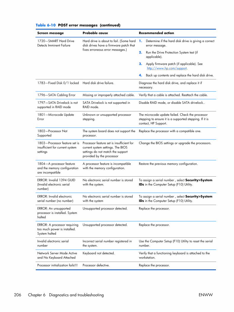
Table 6-10 POST error messages (continued)
Screen message Probable cause Recommended action
1720—SMART Hard DriveDetects Imminent Failure
Hard drive is about to fail. (Some harddisk drives have a firmware patch thatfixes erroneous error messages.)
1. Determine if the hard disk drive is giving a correcterror message.
2. Run the Drive Protection System test (ifapplicable).
3. Apply firmware patch (if applicable). See http://www.hp.com/support.
4. Back up contents and replace the hard disk drive.
1783—Fixed Disk 0/1 locked Hard disk drive failure. Diagnose the hard disk drive, and replace it ifnecessary.
1796—SATA Cabling Error Missing or improperly attached cable. Verify that a cable is attached. Reattach the cable.
1797—SATA Drivelock is notsupported in RAID mode
SATA Drivelock is not supported inRAID mode.
Disable RAID mode, or disable SATA drivelock..
1801—Microcode UpdateError
Unknown or unsupported processorstepping.
The microcode update failed. Check the processorstepping to ensure it is a supported stepping. If it iscontact, HP Support.
1802—Processor NotSupported
The system board does not support theprocessor.
Replace the processor with a compatible one.
1803—Processor feature set isinsufficient for current systemsettings
Processor feature set is insufficient forcurrent system settings. The BIOSsettings do not match the supportprovided by the processor
Change the BIOS settings or upgrade the processors.
1804—A processor featureand the memory configurationare incompatible
A processor feature is incompatiblewith the memory configuration.
Restore the previous memory configuration.
ERROR: Invalid 1394 GUID(Invalid electronic serialnumber)
No electronic serial number is storedwith the system.
To assign a serial number , select Security>SystemIDs in the Computer Setup (F10) Utility.
ERROR: Invalid electronicserial number (no number)
No electronic serial number is storedwith the system
To assign a serial number , select Security>SystemIDs in the Computer Setup (F10) Utility.
ERROR: An unsupportedprocessor is installed. Systemhalted
Unsupported processor detected. Replace the processor.
ERROR: A processor requiringtoo much power is installed.System halted
Unsupported processor detected. Replace the processor.
Invalid electronic serialnumber
Incorrect serial number registered inthe system.
Use the Computer Setup (F10) Utility to reset the serialnumber.
Network Server Mode Activeand No Keyboard Attached
Keyboard not detected. Verify that a functioning keyboard is attached to theworkstation.
Processor initialization fails!!! Processor defective. Replace the processor.
206 Chapter 6 Diagnostics and troubleshooting ENWW
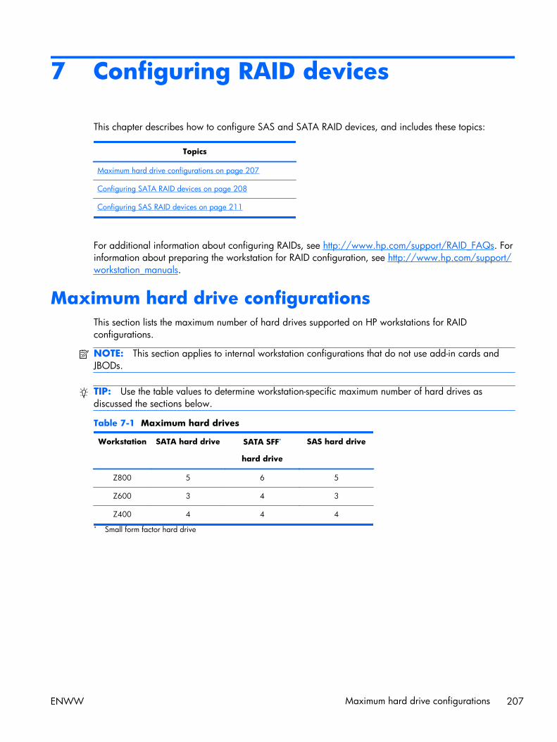
7 Configuring RAID devices
This chapter describes how to configure SAS and SATA RAID devices, and includes these topics:
Topics
Maximum hard drive configurations on page 207
Configuring SATA RAID devices on page 208
Configuring SAS RAID devices on page 211
For additional information about configuring RAIDs, see http://www.hp.com/support/RAID_FAQs. Forinformation about preparing the workstation for RAID configuration, see http://www.hp.com/support/workstation_manuals.
Maximum hard drive configurationsThis section lists the maximum number of hard drives supported on HP workstations for RAIDconfigurations.
NOTE: This section applies to internal workstation configurations that do not use add-in cards andJBODs.
TIP: Use the table values to determine workstation-specific maximum number of hard drives asdiscussed the sections below.
Table 7-1 Maximum hard drives
Workstation SATA hard drive SATA SFF*
hard drive
SAS hard drive
Z800 5 6 5
Z600 3 4 3
Z400 4 4 4
* Small form factor hard drive
ENWW Maximum hard drive configurations 207

Configuring SATA RAID devicesThis section describes how to use the Intel Matrix Storage Manager option ROM Configuration utility toset up and manage SATA RAID volumes.
The following SATA RAID configurations are supported on this workstation:
● Up to the workstation-specific maximum number of internal SATA hard disk drives and eSATAdrives (if you use an optional eSATA bulkhead cable)
● Intel Matrix Storage Manager (IMSM) for Windows
If only a single HDD is attached, the Intel Matrix Storage Manager option ROM does not execute.Associated messages are not displayed.
The Intel SATA AHCI BIOS executes when you select RAID+AHCI for the SATA emulation mode. ThisBIOS is only used to support serial-attached optical drives.
This section does not apply to configuring SATA RAID in the Linux environment. For Linux SATA RAID,refer to the Software RAID in Linux Workstations section in the HP Workstations for Linux User Guide athttp://www.hp.com/support/linux_user_manual.
Attaching SATA HDDsAttach the required minimum number of SATA hard drives for the desired RAID level:
● RAID 0: two or more hard drives
● RAID 1: only two hard drives
● RAID 5: three or more hard drives
● RAID 10: only four hard drives
208 Chapter 7 Configuring RAID devices ENWW
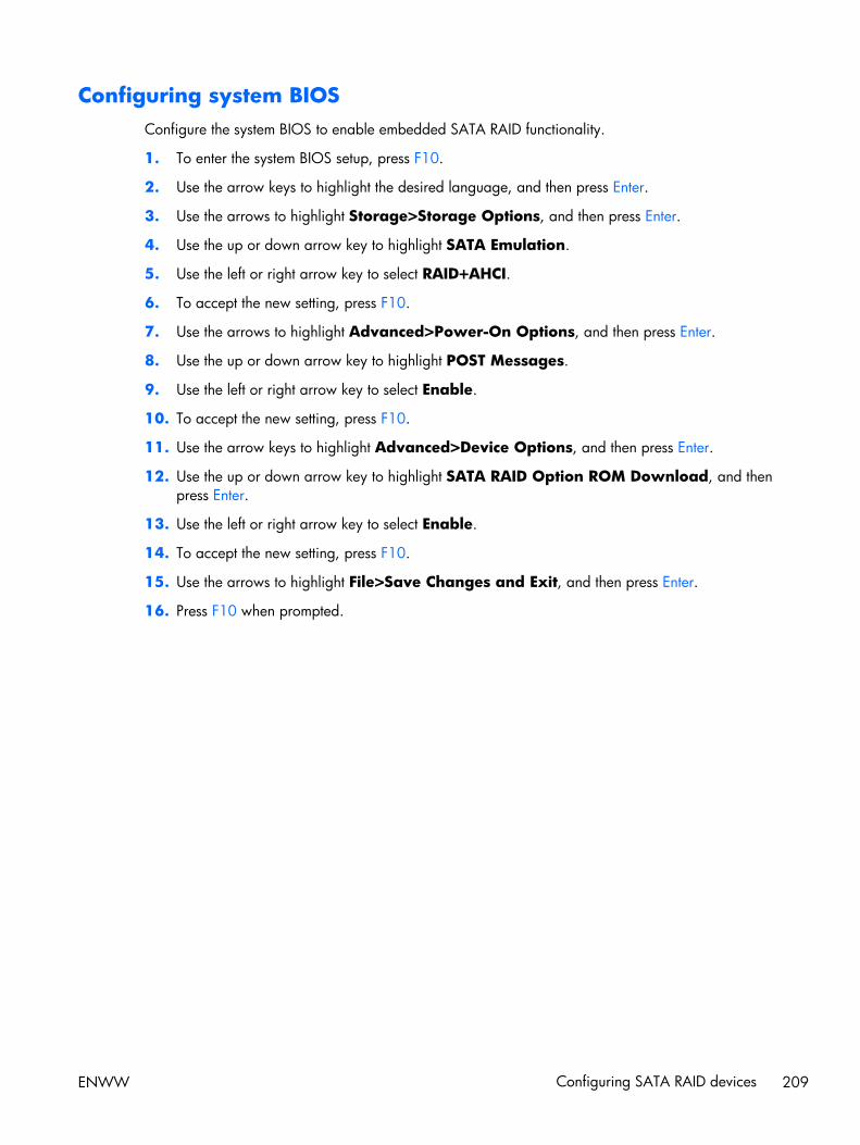
Configuring system BIOSConfigure the system BIOS to enable embedded SATA RAID functionality.
1. To enter the system BIOS setup, press F10.
2. Use the arrow keys to highlight the desired language, and then press Enter.
3. Use the arrows to highlight Storage>Storage Options, and then press Enter.
4. Use the up or down arrow key to highlight SATA Emulation.
5. Use the left or right arrow key to select RAID+AHCI.
6. To accept the new setting, press F10.
7. Use the arrows to highlight Advanced>Power-On Options, and then press Enter.
8. Use the up or down arrow key to highlight POST Messages.
9. Use the left or right arrow key to select Enable.
10. To accept the new setting, press F10.
11. Use the arrow keys to highlight Advanced>Device Options, and then press Enter.
12. Use the up or down arrow key to highlight SATA RAID Option ROM Download, and thenpress Enter.
13. Use the left or right arrow key to select Enable.
14. To accept the new setting, press F10.
15. Use the arrows to highlight File>Save Changes and Exit, and then press Enter.
16. Press F10 when prompted.
ENWW Configuring SATA RAID devices 209

Creating RAID volumesTo create RAID volumes, use the Intel Matrix Storage Manager option ROM Configuration utility.
1. To enter the Intel Matrix Storage Manager option ROM Configuration utility, press Ctrl+l whenprompted
2. If required, see Deleting RAID volumes on page 215 to make enough physical drives available tocreate the RAID volume.
3. Use the up or down arrow key to highlight 1. Create RAID Volume, and then press Enter.
4. Type the desired RAID volume name in the Name: field, and then press Tab.
5. Use the up or down arrow key to select the RAID level in the RAID Level: field, and then press Tab.
6. To display the Select dialog, press Enter.
7. Use the up and down arrow keys and Space to mark individual physical as members of thevolume.
8. To exit the Select dialog and return to the Create Volume Menu dialog, press Enter.
9. If appropriate, use the up or down arrow key to select the Strip Size in the Strip Size: field, andthen press Tab.
10. Enter the desired volume size in the Capacity: field, and then press Tab.
11. Press Enter to initiate volume creation.
12. When prompted, press Y to acknowledge the warning message and create the volume.
13. Return to step 3 to create additional RAID volumes, or use the up or down arrow key to highlight4. Exit, and then press Enter.
14. Press Y when prompted to confirm the exit.
210 Chapter 7 Configuring RAID devices ENWW
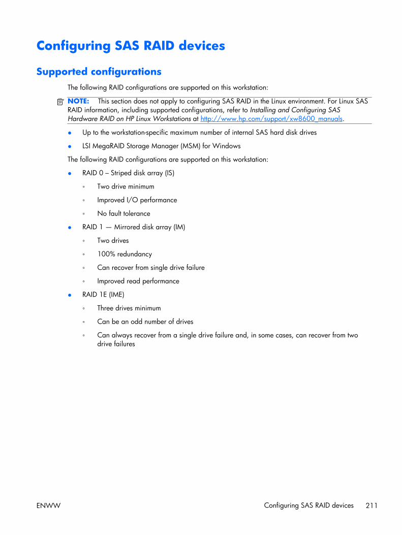
Configuring SAS RAID devices
Supported configurationsThe following RAID configurations are supported on this workstation:
NOTE: This section does not apply to configuring SAS RAID in the Linux environment. For Linux SASRAID information, including supported configurations, refer to Installing and Configuring SASHardware RAID on HP Linux Workstations at http://www.hp.com/support/xw8600_manuals.
● Up to the workstation-specific maximum number of internal SAS hard disk drives
● LSI MegaRAID Storage Manager (MSM) for Windows
The following RAID configurations are supported on this workstation:
● RAID 0 – Striped disk array (IS)
◦ Two drive minimum
◦ Improved I/O performance
◦ No fault tolerance
● RAID 1 — Mirrored disk array (IM)
◦ Two drives
◦ 100% redundancy
◦ Can recover from single drive failure
◦ Improved read performance
● RAID 1E (IME)
◦ Three drives minimum
◦ Can be an odd number of drives
◦ Can always recover from a single drive failure and, in some cases, can recover from twodrive failures
ENWW Configuring SAS RAID devices 211

SAS RAID 0 configurationUse the following procedure to configure an Integrated Striped (IS) volume with the BIOS-basedconfiguration utility. The procedure assumes that the system has the required disk and disk controllers.
1. Start the LSI Corporation Configuration Utility. During BIOS start up, you are prompted to PressCtrl-C to start LSI Corp. Configuration Utility.
2. On the Main menu of the BIOS-based configuration utility, use the arrow keys to select anadapter.
3. Press Enter to go to the Adapter Properties screen.
4. On the Adapter Properties screen, use the arrow keys to select RAID Properties, and press Enterto go to the New Array Type screen.
5. In the Select New Array Type screen, use the arrow keys to select Create IS Volume. PressEnter to go to the Create New Array screen.
6. In the Create New Array screen, use the arrow keys to select the first disk for the IS volume. Thenuse the arrow keys to move to the RAID Disk column for this disk, and press Space and + or - toselect Yes as the value for this column.
If partitions are defined on the selected disk, a message appears warning you that data on thedisk will be lost when the striped volume is created.
7. Press M to migrate, or D to delete the data on the drive.
8. To select additional drives for the striped volume, up to the workstation-specific maximum number,repeat the previous steps.
9. When all drives are selected, press C to create the array once. Use the arrow keys to move toSave changes then exit this menu and press Enter.
10. When the new array is created, the Adapter Properties screen appears. Press Esc twice and selectExit.
212 Chapter 7 Configuring RAID devices ENWW
SAS RAID 1 configurationUse the following procedure to configure an Integrated Mirroring (IM) volume with the BIOS-basedconfiguration utility. The procedure assumes that the system has the required drives and drivecontrollers.
1. Start the LSI Corporation Configuration Utility. During BIOS start up, you are prompted to PressCtrl-C to start LSI Corp. Configuration Utility.
2. On the Main menu of the BIOS-based configuration utility, use the arrow keys to select anadapter.
3. Press Enter to go to the Adapter Properties screen.
4. On the Adapter Properties screen, use the arrow keys to select RAID Properties, and press Enterto go to the New Array Type screen.
5. In the Select New Array Type screen, use the arrow keys to select Create IM Volume. PressEnter.
6. To configure a two-disk mirrored volume with an optional hot spare disk:
a. In the Create New Array screen, use the arrow keys to select the primary disk for the IMvolume (the disk with the data you want to mirror.)
b. Use the arrow keys to move to the RAID Disk column for this disk and press Space to selectYes as the value.
If partitions are defined on the selected disk, a message appears warning you that data onthe disk will be lost when the mirrored volume is created.
c. Press M to migrate or D to delete the data on the drive.
d. The value in the Array Disk column changes to Primary.
Use the arrow keys to select the secondary (mirrored) disk for the IM volume, and then selectYes as the value for the Array Disk column.
If partitions are defined on this disk, a message warns that data on the disk will be lost whenthe mirrored volume is created.
e. Press Delete to confirm erasing data from the disk, or press any other key to deselect the disk.
7. When all drives are selected, press C to create the array once. Use the arrow keys to move toSave changes then exit this menu and press Enter.
8. When the new array is created, the Adapter Properties screen appears. Press Esc twice and selectExit.
ENWW Configuring SAS RAID devices 213
SAS RAID 1E configurationUse the following procedure to configure an Integrated Mirroring Extended (IME) volume with the BIOS-based configuration utility. The procedure assumes that the system has the required disk and diskcontrollers.
1. Start the LSI Corporation Configuration Utility. During BIOS start up, you are prompted to PressCtrl-C to start LSI Corp. Configuration Utility.
2. On the Main menu of the BIOS-based configuration utility, use the arrow keys to select anadapter.
3. Press Enter to go to the Adapter Properties screen.
4. On the Adapter Properties screen, use the arrow keys to select RAID Properties, and press Enterto go to the New Array Type screen.
5. In the Select New Array Type screen, use the arrow keys to select Create IME Volume. PressEnter.
6. To configure a mirrored volume or an optional hot spare drive with up to the workstation-specificmaximum number of drives:
a. In the Create New Array screen, use the arrow keys to select the first disk for the IME volume.
b. Use the arrow keys to move to the RAID Disk column for this disk, and then use the + or - keysto select Yes as the value.
If partitions are defined on the selected disk, a message appears warning that the data onthe disk will be lost when the mirrored volume is created.
c. Press M to migrate, or D to delete the data on the drive.
d. Use the arrow keys to select the next disk for the IME volume, and then select Yes as thevalue for the Array Disk column.
If partitions are defined on this disk, a message warns you that data on the disk will be lostwhen the mirrored volume is created.
e. Press Delete to confirm erasing data from the disk, or press any other key to deselect thedisk.
f. Repeat the previous steps to select up to the workstation-specific maximum number of drivesfor the IME volume, including configuration of a hot spare.
7. When all drives are selected, press C to create the array once. Use the arrow keys to move toSave changes then exit this menu and press Enter.
8. When the new array is created, the Adapter Properties screen appears. Press Esc twice and selectExit.
214 Chapter 7 Configuring RAID devices ENWW
Deleting RAID volumesUse the LSI Logic Corporation Configuration Utility to delete SAS RAID volumes.
1. Start the LSI Corporation Configuration Utility. During BIOS start up, you are prompted to PressCtrl-C to start LSI Corp. Configuration Utility.
2. On the Main menu of the BIOS-based configuration utility, use the arrow keys to select anadapter.
3. Press Enter to go to the Adapter Properties screen.
4. In the Select New Array Type screen, use the arrow keys to select New Existing Array.
5. In the View Array screen, use the arrow keys to select Manage Array. Press Enter.
6. In the Manage Array screen, use the arrow keys to select Delete Array. Press Enter.
Press Y to delete the array and exit to the adapter properties screen.
ENWW Configuring SAS RAID devices 215
8 Configuring password security andresetting CMOS
This chapter describes how to configure password security and to reset CMOS, and includes thesetopics:
Topics
Preparing to configure passwords on page 217
Resetting the password jumper on page 218
Clearing and Resetting the CMOS on page 219
216 Chapter 8 Configuring password security and resetting CMOS ENWW

Preparing to configure passwordsThe Computer Setup (F10) Utility lets you create setup and power-on passwords.
There are three possibilities for setting passwords:
● Define a setup password only
● Define a power-on password only
● Define both
When defining a setup password only, you cannot enter the setup utility without the password.
No password is needed to start from power-on.
When defining a power-on password only, the power-on password is needed to enter F10 Setup or tostart from power-on.
When defining both, the setup password is needed to enter F10 setup and can be used to start frompower-on.
The power-on password cannot be used to enter the F10 Setup Utility, but it can be used to start frompower-on.
One of the passwords will be required to start from power on.
After you create both passwords, you can use the setup password in place of the power-on passwordas an override to log into the workstation (a useful feature for a network administrator).
NOTE: You can only clear the passwords with the password jumper. Clearing CMOS does not clearthe passwords.
CAUTION: Before pressing the Clear CMOS button, back up the workstation CMOS settings.
Pressing the Clear CMOS button resets CMOS values to factory defaults and erases customizedinformation, including asset numbers and special settings.
To back up the CMOS settings, run the Computer Setup (F10) Utility and select Save to Diskettefrom the File menu.
ENWW Preparing to configure passwords 217

Resetting the password jumperUse the following procedure to disable the power-on or setup password features and clear the power-on and setup passwords.
WARNING! To reduce the risk of personal injury from electrical shock and hot surfaces, disconnectthe power cord from the wall outlet and let the internal system components cool before touching.
CAUTION: When the workstation is plugged in, the power supply has voltage applied to the systemboard, even when the workstation is turned off. Failure to disconnect the power cord can result indamage to the workstation.
CAUTION: Static electricity can damage the electronic components of the workstation or optionalequipment. Before beginning these procedures, be sure that you are discharged of static electricity bybriefly touching a grounded metal object.
1. Shut down the operating system, power off the workstation and external devices, and disconnectthe workstation power cord and external devices from power outlets.
2. Disconnect the keyboard, monitor, and other external devices that are connected to theworkstation.
3. Remove the access panel.
4. Locate the password header and jumper.
The password header is E49. The password jumper is green so it can be easily identified.
5. Verify that the AC power cord is disconnected from the power outlet.
6. Remove the jumper from pins 1 and 2.
7. Replace the access panel.
8. Reconnect the external equipment.
9. Reconnect AC power to the workstation.
10. Power on the workstation.
11. Wait for the workstation to display the HP splash screen.
12. Repeat steps 1 through 5.
13. Replace the jumper from pins 1 and 2.
14. Repeat steps 7 through 10.
15. Wait for the workstation to boot to the F10 (Setup) Utility.
16. Use the F10 (Setup) Utility to create the new passwords.
218 Chapter 8 Configuring password security and resetting CMOS ENWW

Clearing and Resetting the CMOSThis section describes the steps necessary to successfully clear and reset the CMOS. The CMOS of theworkstation stores password information and information about the workstation configuration.
Using the CMOS ButtonTo clear CMOS using the Clear CMOS button, use the following procedure:
WARNING! To reduce the risk of personal injury from electrical shock and hot surfaces, disconnectthe power cord from the wall outlet and let the internal system components cool before you touch them.
CAUTION: When the workstation is plugged in, the power supply has voltage applied to the systemboard, even when the workstation is powered off. Failure to disconnect the power cord can result indamage to the workstation.
CAUTION: Static electricity can damage the electronic components of the workstation or optionalequipment. Before beginning these procedures, be sure that you are discharged of static electricity bybriefly touching a grounded metal object.
1. Shut down the operating system, power off the workstation and any external devices, and thendisconnect the workstation power cord and external devices from power outlets.
2. Disconnect the keyboard, monitor, and other external devices that are connected to theworkstation.
3. Remove the access panel.
CAUTION: Before pressing the Clear CMOS button, back up the workstation CMOS settings.
Pressing the Clear CMOS button resets CMOS values to factory defaults and erases customizedinformation, including asset numbers and special settings.
To back up the CMOS settings, run the Computer Setup (F10) Utility and select Save toDiskette from the File menu.
4. Locate, press, and hold the CMOS button for five seconds.
NOTE: Verify that the AC power cord is disconnected from the power outlet.
The CMOS button does not clear CMOS if the power cord is connected.
For assistance locating the CMOS button and other components, see Clearing and Resetting theCMOS on page 219.
5. Replace the access panel.
6. Reconnect external devices.
7. Plug in and power on the workstation. The system boots to a F1 prompt and displays a messagethat the date/time has changed and that system options have changed.
8. Press F1. The system shuts down for three seconds and then powers back on.
9. Use the F10 (Setup) Utility to reset the date and time.
ENWW Clearing and Resetting the CMOS 219
Using the Computer Setup (F10) Utility to Reset CMOSTo reset CMOS using the Computer Setup (F10) Utility:
1. Access the Computer Setup (F10) Utility menu.
2. When the Computer Setup message appears in the lower-right corner of the screen, press F10,and then press Enter to bypass the title screen, if necessary.
If you do not press F10 while the message is displayed, the workstation must be restarted toaccess this utility.
3. From the Computer Setup (F10) Utility menu, select File>Default Setup.
This restores the settings that include boot sequence order and other factory settings. However, itdoes not force hardware rediscovery.
4. Choose Restore Factory Settings as Default, and the press F10 to accept.
5. Select File->Apply Defaults and Exit, and then press F10 to accept.
6. Reset the workstation passwords and configuration information, such as the system date and time.
NOTE: This step does not clear the passwords.
220 Chapter 8 Configuring password security and resetting CMOS ENWW
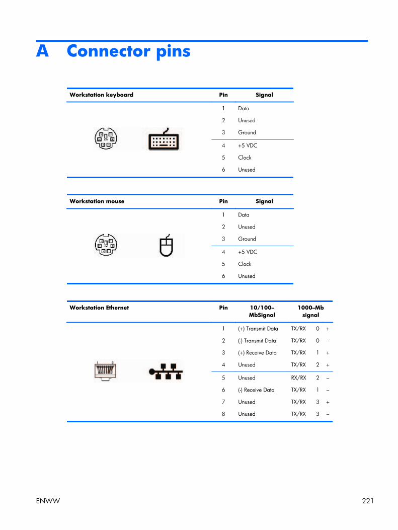
A Connector pins
Workstation keyboard Pin Signal
1
2
3
Data
Unused
Ground
4
5
6
+5 VDC
Clock
Unused
Workstation mouse Pin Signal
1
2
3
Data
Unused
Ground
4
5
6
+5 VDC
Clock
Unused
Workstation Ethernet Pin 10/100–MbSignal
1000–Mbsignal
1
2
3
4
(+) Transmit Data
(-) Transmit Data
(+) Receive Data
Unused
TX/RX
TX/RX
TX/RX
TX/RX
0
0
1
2
+
–
+
+
5
6
7
8
Unused
(-) Receive Data
Unused
Unused
RX/RX
TX/RX
TX/RX
TX/RX
2
1
3
3
–
–
+
–
ENWW 221
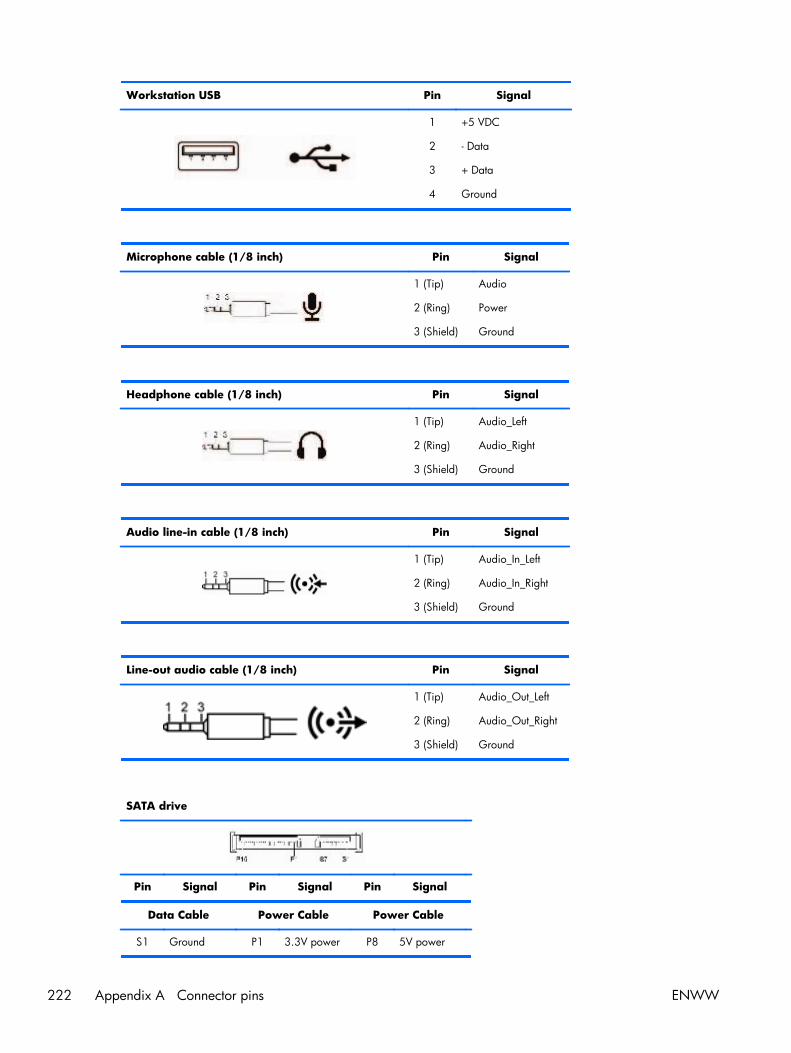
Workstation USB Pin Signal
1
2
3
4
+5 VDC
- Data
+ Data
Ground
Microphone cable (1/8 inch) Pin Signal
1 (Tip)
2 (Ring)
3 (Shield)
Audio
Power
Ground
Headphone cable (1/8 inch) Pin Signal
1 (Tip)
2 (Ring)
3 (Shield)
Audio_Left
Audio_Right
Ground
Audio line-in cable (1/8 inch) Pin Signal
1 (Tip)
2 (Ring)
3 (Shield)
Audio_In_Left
Audio_In_Right
Ground
Line-out audio cable (1/8 inch) Pin Signal
1 (Tip)
2 (Ring)
3 (Shield)
Audio_Out_Left
Audio_Out_Right
Ground
SATA drive
Pin Signal Pin Signal Pin Signal
Data Cable Power Cable Power Cable
S1 Ground P1 3.3V power P8 5V power
222 Appendix A Connector pins ENWW
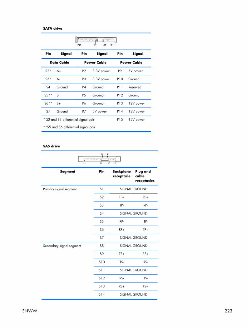
SATA drive
Pin Signal Pin Signal Pin Signal
Data Cable Power Cable Power Cable
S2* A+ P2 3.3V power P9 5V power
S3* A- P3 3.3V power P10 Ground
S4 Ground P4 Ground P11 Reserved
S5** B- P5 Ground P12 Ground
S6** B+ P6 Ground P13 12V power
S7 Ground P7 5V power P14 12V power
* S2 and S3 differential signal pair
**S5 and S6 differential signal pair
P15 12V power
SAS drive
Segment Pin Backplanereceptacle
Plug andcablereceptacles
Primary signal segment S1 SIGNAL GROUND
S2 TP+ RP+
S3 TP- RP-
S4 SIGNAL GROUND
S5 RP- TP-
S6 RP+ TP+
S7 SIGNAL GROUND
Secondary signal segment S8 SIGNAL GROUND
S9 TS+ RS+
S10 TS- RS-
S11 SIGNAL GROUND
S12 RS- TS-
S13 RS+ TS+
S14 SIGNAL GROUND
ENWW 223
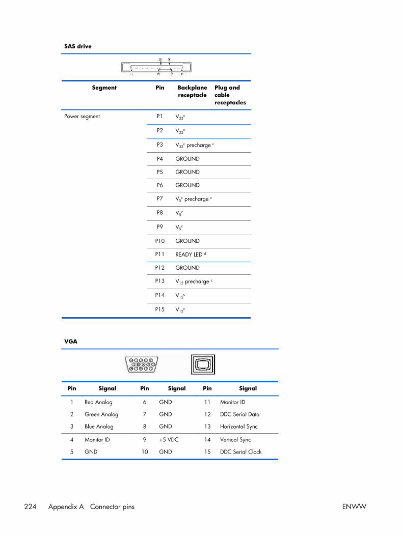
SAS drive
Segment Pin Backplanereceptacle
Plug andcablereceptacles
Power segment P1 V33c
P2 V33c
P3 V33c precharge c
P4 GROUND
P5 GROUND
P6 GROUND
P7 V5c precharge c
P8 V5c
P9 V5c
P10 GROUND
P11 READY LED d
P12 GROUND
P13 V12 precharge c
P14 V12c
P15 V12c
VGA
Pin Signal Pin Signal Pin Signal
1
2
3
Red Analog
Green Analog
Blue Analog
6
7
8
GND
GND
GND
11
12
13
Monitor ID
DDC Serial Data
Horizontal Sync
4
5
Monitor ID
GND
9
10
+5 VDC
GND
14
15
Vertical Sync
DDC Serial Clock
224 Appendix A Connector pins ENWW
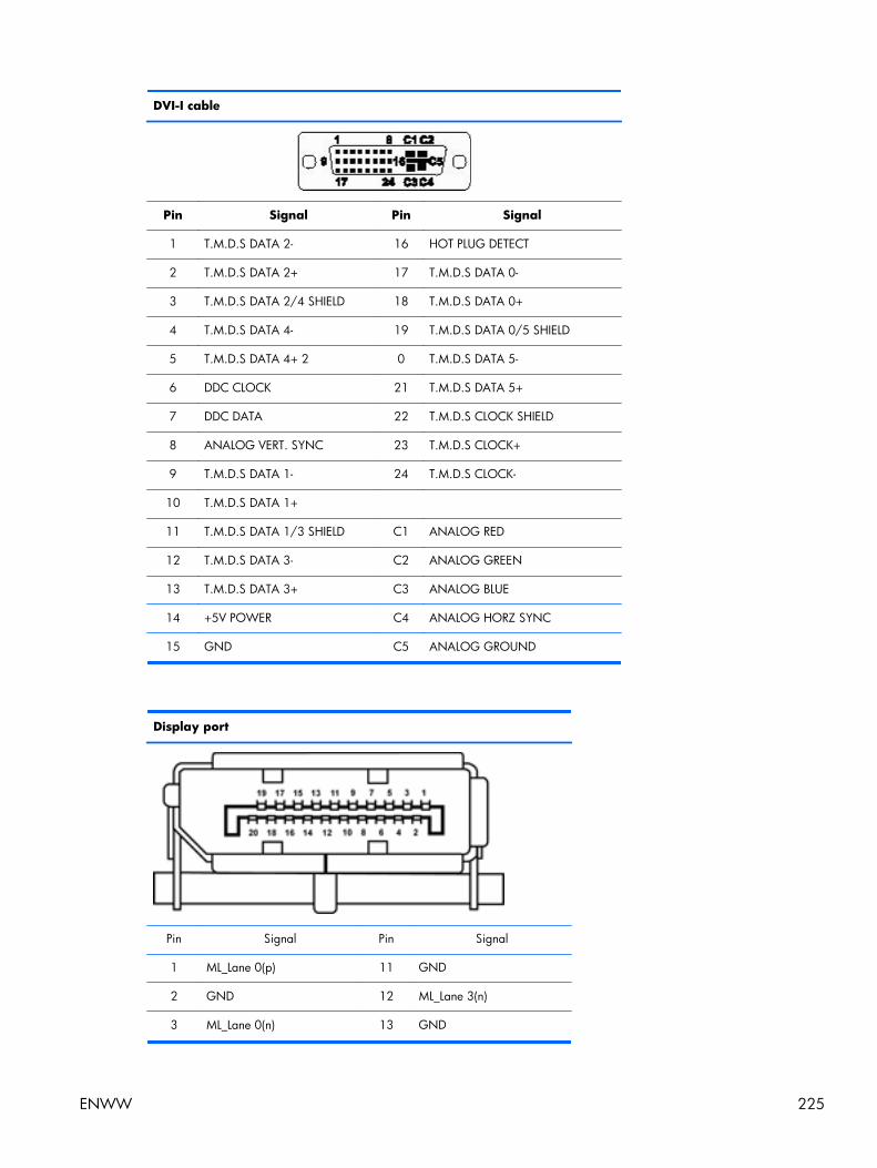
DVI-I cable
Pin Signal Pin Signal
1 T.M.D.S DATA 2- 16 HOT PLUG DETECT
2 T.M.D.S DATA 2+ 17 T.M.D.S DATA 0-
3 T.M.D.S DATA 2/4 SHIELD 18 T.M.D.S DATA 0+
4 T.M.D.S DATA 4- 19 T.M.D.S DATA 0/5 SHIELD
5 T.M.D.S DATA 4+ 2 0 T.M.D.S DATA 5-
6 DDC CLOCK 21 T.M.D.S DATA 5+
7 DDC DATA 22 T.M.D.S CLOCK SHIELD
8 ANALOG VERT. SYNC 23 T.M.D.S CLOCK+
9 T.M.D.S DATA 1- 24 T.M.D.S CLOCK-
10 T.M.D.S DATA 1+
11 T.M.D.S DATA 1/3 SHIELD C1 ANALOG RED
12 T.M.D.S DATA 3- C2 ANALOG GREEN
13 T.M.D.S DATA 3+ C3 ANALOG BLUE
14 +5V POWER C4 ANALOG HORZ SYNC
15 GND C5 ANALOG GROUND
Display port
Pin Signal Pin Signal
1 ML_Lane 0(p) 11 GND
2 GND 12 ML_Lane 3(n)
3 ML_Lane 0(n) 13 GND
ENWW 225
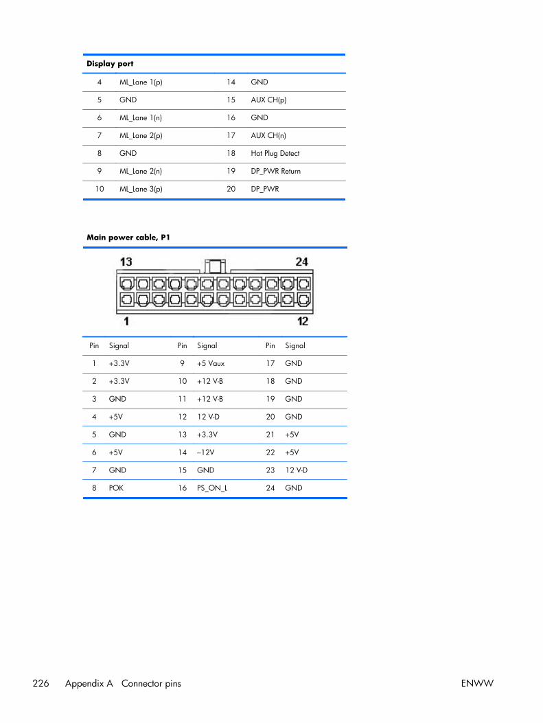
Display port
4 ML_Lane 1(p) 14 GND
5 GND 15 AUX CH(p)
6 ML_Lane 1(n) 16 GND
7 ML_Lane 2(p) 17 AUX CH(n)
8 GND 18 Hot Plug Detect
9 ML_Lane 2(n) 19 DP_PWR Return
10 ML_Lane 3(p) 20 DP_PWR
Main power cable, P1
Pin Signal Pin Signal Pin Signal
1 +3.3V 9 +5 Vaux 17 GND
2 +3.3V 10 +12 V-B 18 GND
3 GND 11 +12 V-B 19 GND
4 +5V 12 12 V-D 20 GND
5 GND 13 +3.3V 21 +5V
6 +5V 14 –12V 22 +5V
7 GND 15 GND 23 12 V-D
8 POK 16 PS_ON_L 24 GND
226 Appendix A Connector pins ENWW
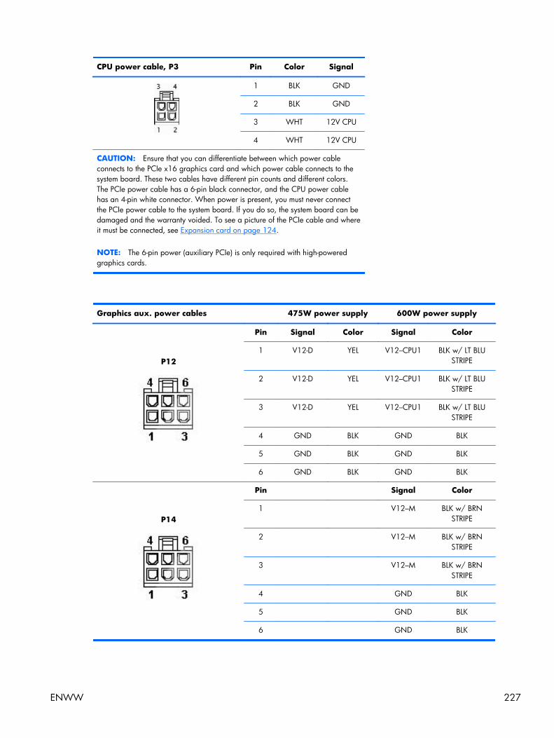
CPU power cable, P3 Pin Color Signal
1 BLK GND
2 BLK GND
3 WHT 12V CPU
4 WHT 12V CPU
CAUTION: Ensure that you can differentiate between which power cableconnects to the PCIe x16 graphics card and which power cable connects to thesystem board. These two cables have different pin counts and different colors.The PCIe power cable has a 6-pin black connector, and the CPU power cablehas an 4-pin white connector. When power is present, you must never connectthe PCIe power cable to the system board. If you do so, the system board can bedamaged and the warranty voided. To see a picture of the PCIe cable and whereit must be connected, see Expansion card on page 124.
NOTE: The 6-pin power (auxiliary PCIe) is only required with high-poweredgraphics cards.
Graphics aux. power cables 475W power supply 600W power supply
P12
Pin Signal Color Signal Color
1 V12-D YEL V12–CPU1 BLK w/ LT BLUSTRIPE
2 V12-D YEL V12–CPU1 BLK w/ LT BLUSTRIPE
3 V12-D YEL V12–CPU1 BLK w/ LT BLUSTRIPE
4 GND BLK GND BLK
5 GND BLK GND BLK
6 GND BLK GND BLK
P14
Pin Signal Color
1 V12–M BLK w/ BRNSTRIPE
2 V12–M BLK w/ BRNSTRIPE
3 V12–M BLK w/ BRNSTRIPE
4 GND BLK
5 GND BLK
6 GND BLK
ENWW 227
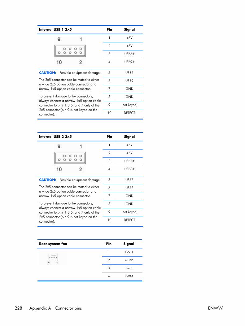
Internal USB 1 2x5 Pin Signal
1 +5V
2 +5V
3 USB6#
4 USB9#
CAUTION: Possible equipment damage.
The 2x5 connector can be mated to eithera wide 2x5 option cable connector or anarrow 1x5 option cable connector.
To prevent damage to the connectors,always connect a narrow 1x5 option cableconnector to pins 1,3,5, and 7 only of the2x5 connector (pin 9 is not keyed on theconnector).
5 USB6
6 USB9
7 GND
8 GND
9 (not keyed)
10 DETECT
Internal USB 2 2x5 Pin Signal
1 +5V
2 +5V
3 USB7#
4 USB8#
CAUTION: Possible equipment damage.
The 2x5 connector can be mated to eithera wide 2x5 option cable connector or anarrow 1x5 option cable connector.
To prevent damage to the connectors,always connect a narrow 1x5 option cableconnector to pins 1,3,5, and 7 only of the2x5 connector (pin 9 is not keyed on theconnector).
5 USB7
6 USB8
7 GND
8 GND
9 (not keyed)
10 DETECT
Rear system fan Pin Signal
1 GND
2 +12V
3 Tach
4 PWM
228 Appendix A Connector pins ENWW
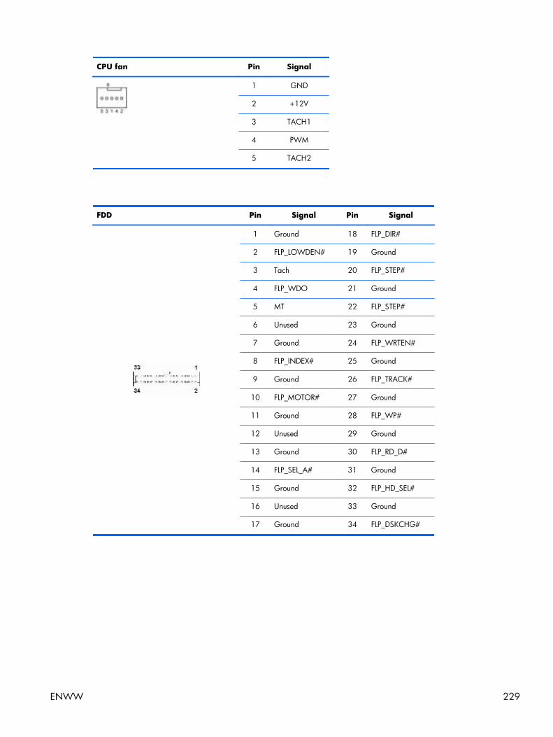
CPU fan Pin Signal
1 GND
2 +12V
3 TACH1
4 PWM
5 TACH2
FDD Pin Signal Pin Signal
1 Ground 18 FLP_DIR#
2 FLP_LOWDEN# 19 Ground
3 Tach 20 FLP_STEP#
4 FLP_WDO 21 Ground
5 MT 22 FLP_STEP#
6 Unused 23 Ground
7 Ground 24 FLP_WRTEN#
8 FLP_INDEX# 25 Ground
9 Ground 26 FLP_TRACK#
10 FLP_MOTOR# 27 Ground
11 Ground 28 FLP_WP#
12 Unused 29 Ground
13 Ground 30 FLP_RD_D#
14 FLP_SEL_A# 31 Ground
15 Ground 32 FLP_HD_SEL#
16 Unused 33 Ground
17 Ground 34 FLP_DSKCHG#
ENWW 229

Internal serial Pin Signal Pin Signal
1 DTR1# 9 +5V
2 RXD1 10 +3.3V AUX
3 CTS1# 11 RTS1#
4 DSR1# 12 COM DETECT
5 TXD1 13 DCD21#
6 RI# 14 -12V
7 Ground 15 +12V
8 Ground
230 Appendix A Connector pins ENWW
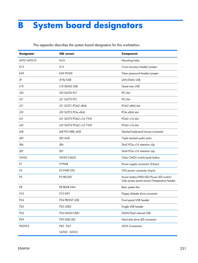
B System board designators
This appendix describes the system board designators for this workstation.
Designator Silk screen Component
MTG1-MTG10 N/A Mounting holes
E15 E15 Crisis recovery header/jumper
E49 E49 PSWD Clear password header/jumper
J9 J9 RJ/USB LAN/DUAL USB
J10 J10 QUAD USB Quad rear USB
J20 J20 SLOT6 PCI PCI slot
J21 J21 SLOT5 PCI PCI slot
J31 J31 SLOT1 PCIe2 x8(4) PCIe2 x8(4) slot
J32 J32 SLOT3 PCIe x8(4) PCIe x8(4) slot
J41 J41 SLOT2 PCIe2 x16 75W PCIe2 x16 slot
J42 J42 SLOT4 PCIe2 x16 75W PCIe2 x16 slot
J68 J68 PS2 KBD_MSE Stacked keyboard/mouse connector
J83 J83 AUD Triple stacked audio jacks
J86 J86 Slot2 PCIe x16 retention clip
J87 J87 Slot4 PCIe x16 retention clip
SW50 SW50 CMOS Clear CMOS switch/push button
P1 P1PWR Power supply connector (24-pin)
P3 P3 PWR CPU CPU power connector (4-pin)
P5 P5 PB/LED Power button/HDD LED/Power LED switch/Side access panel sensor/Temperature header
P8 P8 REAR FAN Rear system fan
P10 P10 FLPY Floppy diskette drive connector
P24 P24 FRONT USB Front panel USB header
P25 P25 USB2 Single USB header
P26 P26 DASH/USB1 DASH/Dual internal USB
P29 P29 HDD LED Hard disk drive LED connector
P60-P63 P60 - P63
SATA0 - SATA3
SATA Connectors
ENWW 231
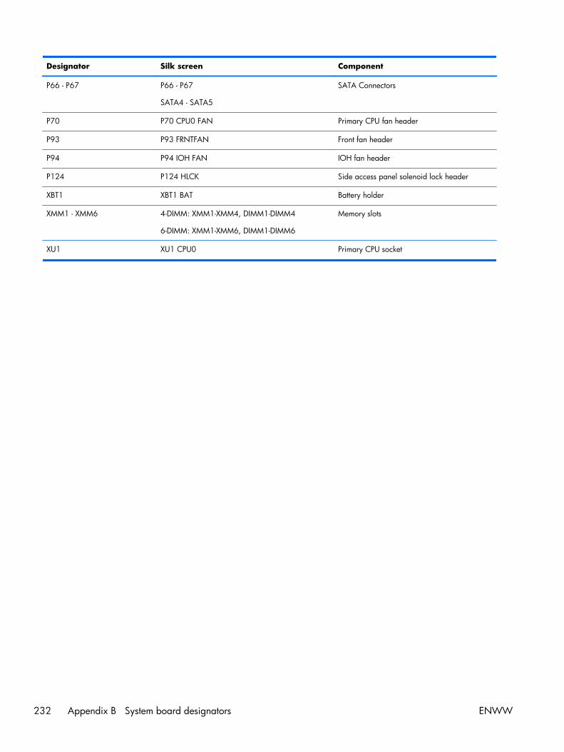
Designator Silk screen Component
P66 - P67 P66 - P67
SATA4 - SATA5
SATA Connectors
P70 P70 CPU0 FAN Primary CPU fan header
P93 P93 FRNTFAN Front fan header
P94 P94 IOH FAN IOH fan header
P124 P124 HLCK Side access panel solenoid lock header
XBT1 XBT1 BAT Battery holder
XMM1 - XMM6 4-DIMM: XMM1-XMM4, DIMM1-DIMM4
6-DIMM: XMM1-XMM6, DIMM1-DIMM6
Memory slots
XU1 XU1 CPU0 Primary CPU socket
232 Appendix B System board designators ENWW
C Routine Care
General cleaning safety precautions● Never use solvents or flammable solutions to clean the workstation.
● Never immerse any component in water or cleaning solutions; apply any liquids to a clean clothand then use the cloth on the component.
● Always unplug the workstation before cleaning the keyboard, mouse, or air vents.
● Always disconnect the keyboard before cleaning it.
● Wear safety glasses equipped with side shields when cleaning the keyboard.
Cleaning the workstation case● Follow the safety precautions presented (Service considerations on page 66) before cleaning the
workstation.
● To remove light stains or dirt, use plain water with a clean, lint-free cloth or swab.
● For stronger stains, use a mild dish washing liquid diluted with water. Rinse well by wiping it witha cloth or swab dampened with clear water.
● For stubborn stains, use isopropyl (rubbing) alcohol. No rinsing is required because the alcoholevaporates quickly and does not leave a residue.
● After cleaning, always wipe the workstation with a clean, lint-free cloth.
● Occasionally, clean the air vents on the workstation. Lint and other foreign matter can block thevents and limit the airflow.
Cleaning the keyboardCAUTION: Use safety glasses equipped with side shields before attempting to clean debris fromunder the keys.
● Follow the safety precautions presented (Service considerations on page 66) before cleaning theworkstation.
● Visible debris underneath or between the keys can be removed by vacuuming or shaking.
● Canned, pressurized air can be used to clean debris from under the keys. Use caution becausetoo much air pressure can dislodge lubricants applied under the wide keys.
● If you remove a key, use a specially designed key remover to prevent damage to the keys. Thistool is available from many electronic supply outlets.
CAUTION: Never remove a wide key (like the space bar key) from the keyboard. If these keysare improperly removed or installed, the keyboard might not function properly.
ENWW General cleaning safety precautions 233

● Clean under a key with a swab moistened with isopropyl alcohol and squeezed out. Be carefulnot to wipe away lubricants necessary for proper key functions. Allow the parts to air dry beforereassembly.
● Use tweezers to remove any fibers or dirt in confined areas.
Cleaning the monitor● Follow the safety precautions presented (Service considerations on page 66) before cleaning the
workstation.
● To clean the monitor, wipe the monitor screen with a towelette designed for cleaning monitors or aclean cloth moistened with water.
CAUTION: Do not use sprays or aerosols directly on the screen—the liquid might seep into thehousing and damage a component.
Never use solvents or flammable liquids on the monitor because display or housing damage mayresult.
Cleaning the mouse1. Follow the safety precautions presented (Service considerations on page 66) before cleaning the
workstation.
2. Remove the mouse ball from the housing by removing the retaining plate.
3. Clean the mouse ball.
4. Pull out any debris from the ball socket, and wipe the ball with a clean, dry cloth.
5. Reassemble the mouse.
234 Appendix C Routine Care ENWW

D Locating HP resources
This section provides information on the following HP resources for your workstation:
Topics
Product information on page 236
● HP Cool Tools
● Regulatory information
● Accessories
● System board
● Serial number and Certificate of Authenticity labels
● Linux
Product support on page 237
● Additional information
● Technical support
● Business Support Center
● IT Resource Center
● HP Service Center
● HP Business and IT Services
● Warranty information
Product documentation on page 238
● User and third-party documentation, and white papers
● Product notifications
● QuickSpecs
● Customer Advisories, Security Bulletins, Notices
Product diagnostics on page 239
● Diagnostics tools
● Audible beeps and LED code definitions
● Web-based support tools
Product updates on page 240
● Software, BIOS, and driver updates
● Operating system reinstallation
● Operating system
ENWW 235
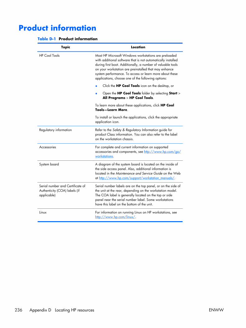
Product informationTable D-1 Product information
Topic Location
HP Cool Tools Most HP Microsoft Windows workstations are preloadedwith additional software that is not automatically installedduring first boot. Additionally, a number of valuable toolson your workstation are preinstalled that may enhancesystem performance. To access or learn more about theseapplications, choose one of the following options:
● Click the HP Cool Tools icon on the desktop, or
● Open the HP Cool Tools folder by selecting Start >All Programs > HP Cool Tools.
To learn more about these applications, click HP CoolTools—Learn More.
To install or launch the applications, click the appropriateapplication icon.
Regulatory information Refer to the Safety & Regulatory Information guide forproduct Class information. You can also refer to the labelon the workstation chassis.
Accessories For complete and current information on supportedaccessories and components, see http://www.hp.com/go/workstations.
System board A diagram of the system board is located on the inside ofthe side access panel. Also, additional information islocated in the Maintenance and Service Guide on the Webat http://www.hp.com/support/workstation_manuals/.
Serial number and Certificate ofAuthenticity (COA) labels (ifapplicable)
Serial number labels are on the top panel, or on the side ofthe unit at the rear, depending on the workstation model.The COA label is generally located on the top or sidepanel near the serial number label. Some workstationshave this label on the bottom of the unit.
Linux For information on running Linux on HP workstations, seehttp://www.hp.com/linux/.
236 Appendix D Locating HP resources ENWW

Product supportTable D-2 Product support
Topic Location
Additional information For online access to technical support information andtools, see http://www.hp.com/go/workstationsupport.
Support resources include Web-based troubleshootingtools, technical knowledge databases, driver and patchdownloads, online communities, and proactive notificationservices.
The following communication and diagnostic tools are alsoavailable:
● Instant Chat
● Instant Support
● Diagnose Problem
Refer to the workstation Maintenance and Service Guidefor more information on how to receive support.
Technical support Before you call technical support, refer to the workstationMaintenance and Service Guide for a listing of informationyou need to have available before you call.
For a listing of all worldwide technical support phonenumbers, see http://www.hp.com/support/, select yourregion, and click Contact HP in the upper-left corner.
Business Support Center (BSC) For software/driver downloads, warranty information,single-topic documents, user manuals, or service manuals,see http://www.hp.com/go/bizsupport.
IT Resource Center (ITRC) See http://www.itrc.hp.com/ for a searchable knowledgebase for IT professionals.
HP Business and IT Services. For business and IT information, see http://www.hp.com/hps/.
HP Hardware Support Services For hardware service information, seehttp://h20219.www2.hp.com/services/us/en/always-on/hardware-support-supporting-information.html?jumpid=reg_R1002_USEN.
Warranty information To locate base warranty information, seehttp://www.hp.com/support/warranty-lookuptool.
To locate an existing Care Pack, see http://www.hp.com/go/lookuptool.
To extend a standard product warranty, seehttp://h20219.www2.hp.com/services/us/en/warranty/carepack-overview.html?jumpid=hpr_R1002_USEN. HPCare Pack Services offer upgraded service levels to extendand expand a standard product warranty.
ENWW Product support 237
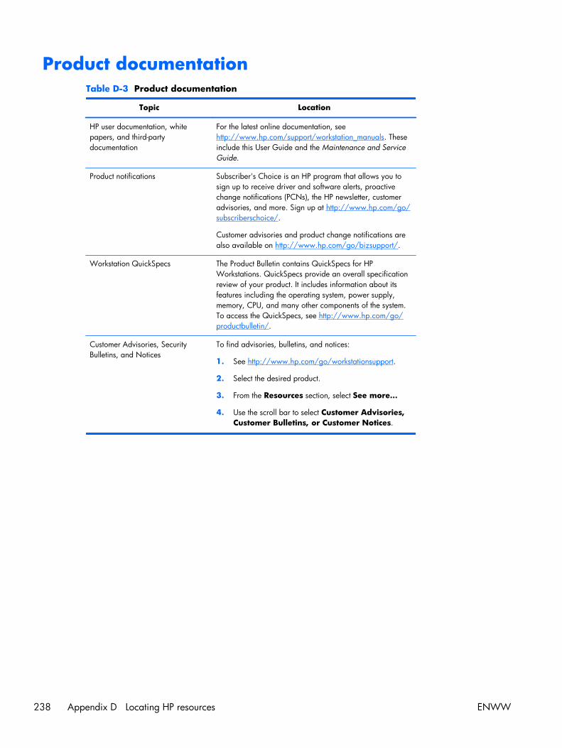
Product documentationTable D-3 Product documentation
Topic Location
HP user documentation, whitepapers, and third-partydocumentation
For the latest online documentation, seehttp://www.hp.com/support/workstation_manuals. Theseinclude this User Guide and the Maintenance and ServiceGuide.
Product notifications Subscriber's Choice is an HP program that allows you tosign up to receive driver and software alerts, proactivechange notifications (PCNs), the HP newsletter, customeradvisories, and more. Sign up at http://www.hp.com/go/subscriberschoice/.
Customer advisories and product change notifications arealso available on http://www.hp.com/go/bizsupport/.
Workstation QuickSpecs The Product Bulletin contains QuickSpecs for HPWorkstations. QuickSpecs provide an overall specificationreview of your product. It includes information about itsfeatures including the operating system, power supply,memory, CPU, and many other components of the system.To access the QuickSpecs, see http://www.hp.com/go/productbulletin/.
Customer Advisories, SecurityBulletins, and Notices
To find advisories, bulletins, and notices:
1. See http://www.hp.com/go/workstationsupport.
2. Select the desired product.
3. From the Resources section, select See more…
4. Use the scroll bar to select Customer Advisories,Customer Bulletins, or Customer Notices.
238 Appendix D Locating HP resources ENWW

Product diagnosticsTable D-4 Product diagnostics
Topic Location
Diagnostics tools The HP Vision Field Diagnostics utility can be downloadedfrom the HP Web site. To use this utility, refer to theappropriate section of the workstation Maintenance andService Guide.
Audible beep and LED codedefinitions
Refer to the appropriate section of the workstationMaintenance and Service Guide for detailed informationabout beep and Light Emitting Diode (LED) codesapplicable to the workstation.
ENWW Product diagnostics 239

Product updatesTable D-5 Product updates
Topic Location
Software, BIOS, and driverupdates
See http://www.hp.com/go/workstationsupport to verify thatyou have the latest drivers for the workstation.
To locate the current workstation BIOS on your MicrosoftWindows workstation, select Start>Help andSupport>Pick a Task>Use Tools toview...>Tools>My Computer Information>Viewgeneral system information....
Operating system For information on operating systems supported on HPworkstations, see http://www.hp.com/go/wsos.
240 Appendix D Locating HP resources ENWW
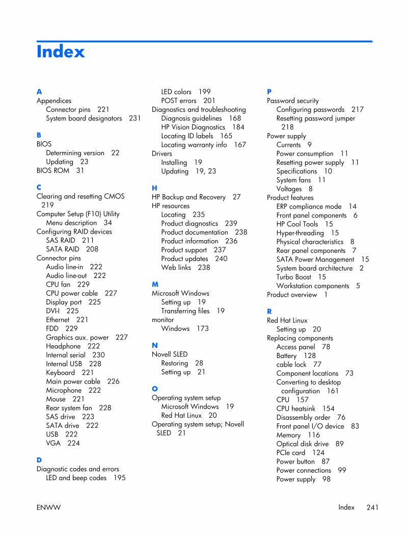
Index
AAppendices
Connector pins 221System board designators 231
BBIOS
Determining version 22Updating 23
BIOS ROM 31
CClearing and resetting CMOS
219Computer Setup (F10) Utility
Menu description 34Configuring RAID devices
SAS RAID 211SATA RAID 208
Connector pinsAudio line-in 222Audio line-out 222CPU fan 229CPU power cable 227Display port 225DVI-I 225Ethernet 221FDD 229Graphics aux. power 227Headphone 222Internal serial 230Internal USB 228Keyboard 221Main power cable 226Microphone 222Mouse 221Rear system fan 228SAS drive 223SATA drive 222USB 222VGA 224
DDiagnostic codes and errors
LED and beep codes 195
LED colors 199POST errors 201
Diagnostics and troubleshootingDiagnosis guidelines 168HP Vision Diagnostics 184Locating ID labels 165Locating warranty info 167
DriversInstalling 19Updating 19, 23
HHP Backup and Recovery 27HP resources
Locating 235Product diagnostics 239Product documentation 238Product information 236Product support 237Product updates 240Web links 238
MMicrosoft Windows
Setting up 19Transferring files 19
monitorWindows 173
NNovell SLED
Restoring 28Setting up 21
OOperating system setup
Microsoft Windows 19Red Hat Linux 20
Operating system setup; NovellSLED 21
PPassword security
Configuring passwords 217Resetting password jumper
218Power supply
Currents 9Power consumption 11Resetting power supply 11Specifications 10System fans 11Voltages 8
Product featuresERP compliance mode 14Front panel components 6HP Cool Tools 15Hyper-threading 15Physical characteristics 8Rear panel components 7SATA Power Management 15System board architecture 2Turbo Boost 15Workstation components 5
Product overview 1
RRed Hat Linux
Setting up 20Replacing components
Access panel 78Battery 128cable lock 77Component locations 73Converting to desktop
configuration 161CPU 157CPU heatsink 154Disassembly order 76Front panel I/O device 83Memory 116Optical disk drive 89PCIe card 124Power button 87Power connections 99Power supply 98
ENWW Index 241
Predisassembly 75Rear system fan 100Self-repair 71Service considerations 66side access panel sensor 79side access panel solenoid 82Slot identification 121System board 159Workstation speaker 97
RestorePlus! 25Restoring the operating system
Restore methods 24Windows Vista 25Windows XP 26
SSoftware
Ordering 25Support
Locating HP resources 235
UUpdating the workstation
First boot update 21Updating drivers 23Updating the BIOS 23
WWindows operating system
monitor 173Windows Vista
Restoring 25Setting up 19
Windows XPRestoring 26Setting up 19
Workstation managementAltiris Client Management
Solutions 47Dual-state power button 63FailSafe Boot Block ROM 51Fault notification and recovery
62HP Client Manager Software
47HP SoftPaq Download
Manager 48HPQFlash 50Initial configuration 44Proactive Change Notification
49
Remote ROM Flash 50Remote system install 44Replicating the setup 45ROM Flash 50Subscriber's Choice 49System Software Manager 49Updating software 47Workstation security 52
Workstation setupEnsuring proper ventilation 16
242 Index ENWW