HP Pavilion x2 Detachable Notebook PCHP x2 210 G1 Tablet ...
88
HP Pavilion x2 Detachable Notebook PC HP x2 210 G1 Tablet Maintenance and Service Guide IMPORTANT! This document is intended for HP authorized service providers only.
Transcript of HP Pavilion x2 Detachable Notebook PCHP x2 210 G1 Tablet ...
HP Pavilion x2 Detachable Notebook PCHP x2 210 G1 Tablet
Maintenance and Service GuideIMPORTANT! This document is intended for HP authorized service providers only.

© Copyright 2015, 2016 HP Development Company, L.P.
Bluetooth is a trademark owned by its proprietor and used by HP Inc. under license. Intel is a U.S. registered trademark of Intel Corporation. Microsoft and Windows are U.S. registered trademarks of Microsoft Corporation. SD Logo is a trademark of its proprietor.
The information contained herein is subject to change without notice. The only warranties for HP products and services are set forth in the express warranty statements accompanying such products and services. Nothing herein should be construed as constituting an additional warranty. HP shall not be liable for technical or editorial errors or omissions contained herein.
Third Edition: January 2016
First Edition: June 2015
Document Part Number: 814660-003
Product notice
This guide describes features that are common to most products. Some features may not be available on your tablet.
Software terms
By installing, copying, downloading, or otherwise using any software product preinstalled on this tablet, you agree to be bound by the terms of the HP End User License Agreement (EULA). If you do not accept these license terms, your sole remedy is to return the entire unused product (hardware and software) within 14 days for a refund subject to the refund policy of your place of purchase.
For any further information or to request a full refund of the tablet, please contact your local point of sale (the seller).

Safety warning notice
WARNING! To reduce the possibility of heat-related injuries or of overheating the device, do not place the device directly on your lap or obstruct the device air vents. Use the device only on a hard, flat surface. Do not allow another hard surface, such as an adjoining optional printer, or a soft surface, such as pillows or rugs or clothing, to block airflow. Also, do not allow the AC adapter to contact the skin or a soft surface, such as pillows or rugs or clothing, during operation. The device and the AC adapter comply with the user-accessible surface temperature limits defined by the International Standard for Safety of Information Technology Equipment (IEC 60950).
iii

iv Safety warning notice

Table of contents
1 Product description ....................................................................................................................................... 1
2 External component identification .................................................................................................................. 3
Right side ............................................................................................................................................................... 3
Left side ................................................................................................................................................................. 4
Display .................................................................................................................................................................... 5
Top edge ................................................................................................................................................................. 6
Bottom edge .......................................................................................................................................................... 6
3 Illustrated parts catalog ................................................................................................................................ 7
Locating the product number and serial number ................................................................................................. 7
Tablet major components ...................................................................................................................................... 9
Miscellaneous parts ............................................................................................................................................. 12
Sequential part number listing ........................................................................................................................... 13
4 Removal and replacement preliminary requirements ..................................................................................... 21
Tools required ...................................................................................................................................................... 21
Service considerations ......................................................................................................................................... 21
Plastic parts ....................................................................................................................................... 21
Cables and connectors ...................................................................................................................... 21
Grounding guidelines ........................................................................................................................................... 22
Electrostatic discharge damage ........................................................................................................ 22
Packaging and transporting guidelines .......................................................................... 23
Workstation guidelines ................................................................................ 23
5 Removal and replacement procedures for Authorized Service Provider parts ................................................... 25
Releasing the tablet from the keyboard base ..................................................................................................... 25
Tablet component replacement procedures ....................................................................................................... 25
Unlocking the device and disabling Always On Remote Management (select products only) ........................... 26
Back cover ............................................................................................................................................................ 26
Battery ................................................................................................................................................................. 28
Audio board .......................................................................................................................................................... 30
Speakers .............................................................................................................................................................. 31
Touch board ......................................................................................................................................................... 33
System board ....................................................................................................................................................... 34
Wireless antenna ................................................................................................................................................. 37
v

Power/volume button board ............................................................................................................................... 38
Webcam module .................................................................................................................................................. 40
Middle frame ........................................................................................................................................................ 42
POGO (10-pin) docking connector cable ............................................................................................................. 43
Keyboard base ..................................................................................................................................................... 44
Hard drive (select products only) ........................................................................................................................ 46
Keyboard board ................................................................................................................................................... 47
TouchPad .............................................................................................................................................................. 48
Hinge cover .......................................................................................................................................................... 49
POGO connector ................................................................................................................................................... 51
6 Using Setup Utility (BIOS) in Windows 10 ....................................................................................................... 53
Starting Setup Utility (BIOS) ................................................................................................................................ 53
Updating Setup Utility (BIOS) .............................................................................................................................. 53
Determining the BIOS version ........................................................................................................... 53
Downloading a BIOS update .............................................................................................................. 54
Synchronizing a tablet and keyboard (select products only) .............................................................................. 55
7 Using HP PC Hardware Diagnostics (UEFI) in Windows 10 ................................................................................. 56
Downloading HP PC Hardware Diagnostics (UEFI) to a USB device .................................................................... 56
8 Using Setup Utility (BIOS) and HP PC Hardware Diagnostics (UEFI) in Windows 8.1 ............................................. 58
Starting Setup Utility (BIOS) ................................................................................................................................ 58
Updating Setup Utility (BIOS) .............................................................................................................................. 58
Determining the BIOS version ........................................................................................................... 58
Downloading a BIOS update .............................................................................................................. 59
Using HP PC Hardware Diagnostics (UEFI) ........................................................................................................... 60
Downloading HP PC Hardware Diagnostics (UEFI) to a USB device .................................................. 60
9 Specifications .............................................................................................................................................. 62
10 Backing up, restoring, and recovering in Windows 10 .................................................................................... 63
Creating recovery media and backups ................................................................................................................ 63
Creating HP Recovery media (select products only) ......................................................................... 63
Using Windows tools ........................................................................................................................................... 64
Restore and recovery ........................................................................................................................................... 65
Recovering using HP Recovery Manager ........................................................................................... 65
What you need to know before you get started ............................................................. 65
Using the HP Recovery partition (select products only) ................................................. 66
Using HP Recovery media to recover .............................................................................. 66
vi

Changing the computer boot order ................................................................................ 67
Removing the HP Recovery partition (select products only) ......................................... 68
11 Backing up, restoring, and recovering in Windows 8.1 ................................................................................... 69
Creating recovery media and backups ................................................................................................................ 69
Creating HP Recovery media (select products only) ......................................................................... 69
Using Windows tools ........................................................................................................................................... 70
Restore and recovery ........................................................................................................................................... 70
Recovering using HP Recovery Manager ........................................................................................... 71
What you need to know before you get started ............................................................. 71
Using the HP Recovery partition (select products only) ................................................. 72
Using HP Recovery media to recover .............................................................................. 72
Changing the computer boot order ................................................................................ 72
Removing the HP Recovery partition (select products only) ......................................... 73
12 Power cord set requirements ...................................................................................................................... 74
Requirements for all countries ............................................................................................................................ 74
Requirements for specific countries and regions ................................................................................................ 75
13 Recycling .................................................................................................................................................. 77
Index ............................................................................................................................................................. 78
vii

viii

1 Product description
Category Description
Product Name HP Pavilion x2 Detachable
HP x2 210 G1 Tablet
Processor Intel Z8300 1.44 GHz quad core processor soldered-on-circuit (SoC)
Panel 10.1-in (1280x800), Antiglare (AG), light-emitting diode (LED), WXGA, TouchScreen display panel
Graphics Internal graphics:
Intel 7th generation graphics and media encode/decode engine 2D/3D graphics
Supports DX11, OpenGL 3.0 (OGL 3.0), OpenCL 1.2 (OCL 1.2), and OpenGLES 2.0 (OGLES 2.0)
Memory On-board; non-accessible
2 GB DDR3L or 4 GB DDR3L
Supports up to 2 GB or 4 GB (select products only) maximum system memory
Mass storage Supports 32- or 64-GB eMMC (v5.0)
Audio and video Stereo speakers (2)
Dual array digital microphones with appropriate beam-forming, echo-cancellation, and noise-suppression software
Audio codec ALC5642
HD webcam: 1/6-in, F2.4, 1.26-MP max., (1280x720), 720P, 30 fps
Sensor Accelerometer
Ambient Light Sensor
eCompass
Gyroscope
Hall sensor
Thermistor
Wireless networking Integrated wireless options:
Intel 3165NGWG ac, 1x1 Bluetooth 4.0 LE PCIe+USB NGFF 2230 WW (Stone Peak 1)
AzureWave AW-NB177NF Realtek RTL8723BS 802.11 (1x1 b/g/n, Single Band, Bluetooth 4.0) with single antenna (SDIO+UART)
Supports Miracast
External expansion Integrated microSD Card Reader expandable to 2 TB
Supports SD 3.0
Ports ● Audio: headphone/microphone combo jack
● MicroSD Card Reader
● One USB 2.0 port, one USB 2.0 type C port support charging and data
● Micro HDMI v1.4a port supporting up to 2048x1024, 1920x1080 @ 60Hz
1
Category Description
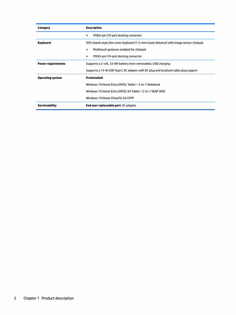
● POGO-pin (10-pin) docking connector
Keyboard 93% island-style thin cover keyboard (1.5-mm travel distance) with image sensor clickpad
● Multitouch gestures enabled for clickpad
● POGO-pin (10-pin) docking connector
Power requirements Supports a 2-cell, 33-Wh battery (non-removable), USB charging
Supports a 15-W USB Type C AC adapter with DC plug and localized cable plug support
Operating system Preinstalled:
Windows 10 Home Entry EM/SL Tablet + 2-in-1 Notebook
Windows 10 Home Entry EM/SL 64 Tablet + 2-in-1 SEAP (APJ)
Windows 10 Home China/SL 64 CPPP
Serviceability End user replaceable part: AC adapter
2 Chapter 1 Product description

2 External component identification
Right side
Component Description
(1) Volume buttons Control speaker volume on the tablet.
▲ To increase speaker volume, press the + edge of the button.
(2) Windows button Opens the Start menu.
(3) Memory card reader Reads optional memory cards that enable you to store, manage, share or access information.
To insert a card:
1. Hold the card label-side up, with connectors facing the computer.
2. Insert the card into the memory card reader, and then press in on the card until it is firmly seated.
To remove a card:
▲ Press in on the card, and then remove it from the memory card reader.
(4) HDMI port Connects an optional video or audio device, such as a high-definition television, any compatible digital or audio component, or a high-speed High-Definition Multimedia Interface (HDMI) device.
(5) USB Type-C port Connects any device with a Type-C connector.
NOTE: Some USB Type-C ports can charge select models of cell phones, laptops, tablets, and MP3 players. even when the computer is off. Some can also connect DisplayPort, VGA, HDMI, and other video devices.
(6) AC adapter and battery light ● White: The AC adapter is connected and the battery is fully charged.
● Amber: The AC adapter is connected, and the battery is charging.
Right side 3

● White: The AC adapter is disconnected, and the battery has reached a low battery level.
● Blinking amber: The battery is not charging.
(7) USB 3.0 port Connects optional USB 3.0 devices and provides enhanced USB power performance.
Left side
Component Description
Audio-out (headphone)/Audio-in (microphone) jack
Connects optional powered stereo speakers, headphones, earbuds, a headset, or a television audio cable. Also connects an optional headset microphone. This jack does not support optional microphone-only devices.
WARNING! To reduce the risk of personal injury, lower the volume setting before putting on headphones, earbuds, or a headset. For additional safety information, refer to the Regulatory, Safety, and Environmental Notices.
To access this document:
▲ Type support in the taskbar search box, and then select the HP Support Assistant app.
‒ or –
Click the question mark icon in the taskbar.
NOTE: When a device is connected to the jack, the computer speakers are disabled.
NOTE: Be sure that the device cable has a 4-conductor connector that supports both audio-out (headphone) and audio-in (microphone).
4 Chapter 2 External component identification

Display
Component Description
(1) WLAN antennas (2)* Send and receive wireless signals to communicate with wireless local area networks (WLANs).
(2) Webcam Records video and captures photographs. Some products allow you to video conference and chat online using streaming video.
To use the webcam:
▲ Type camera in the taskbar search box, and then select Camera.
(3) Webcam light On: The webcam is in use.
(4) Ambient light sensor Automatically adjusts the display brightness based on the lighting conditions in your environment.
(5) Speakers (2) Produce sound.
*The antenna is not visible from the outside of the computer. For optimal transmission, keep the areas immediately around the antennas free from obstructions.
For wireless regulatory notices, see the section of the Regulatory, Safety, and Environmental Notices that applies to your country or region.
To access this document:
Type support in the taskbar search box, and then select the HP Support Assistant app.
‒ or –
Click the question mark icon in the taskbar.
Display 5

Top edge
Component Description
(1) Power button ● When the tablet is off, press the button to turn on the tablet.
● When the tablet is on, press the button briefly to initiate Sleep.
● When the tablet is in the Sleep state, press the button briefly to exit Sleep.
● When the tablet is in Hibernation, press the button briefly to exit Hibernation.
CAUTION: Pressing and holding down the power button will result in the loss of unsaved information.
If the tablet has stopped responding and Windows shutdown procedures are ineffective, press and hold the power button down for at least 10 seconds to turn off the tablet.
To learn more about your power settings, see your power options. Type power in the taskbar search box, select Power and sleep settings, and then select Power and sleep.
(2) Internal microphones Record sound.
Bottom edge
Component Description
(1) Alignment posts(2) Allow the display to open and close.
(2) Docking port Connects the tablet to the keyboard base.
(3) Product and regulatory information Identifies serial number, product number, and regulatory labels
6 Chapter 2 External component identification

3 Illustrated parts catalog
NOTE: HP continually improves and changes product parts. For complete and current information on supported parts for your computer, go to http://partsurfer.hp.com, select your country or region, and then follow the on-screen instructions.
Locating the product number and serial numberThe tablet serial number and product number are etched on the tablet bottom edge (3).
– or –
The serial number (2) and product number (3) are also located on a label inside the back cover.
This information may be needed when travelling internationally or when contacting support.
Component
(1) Data matrix code
Locating the product number and serial number 7

Component
(2) Serial number
(3) Product number
(4) Warranty period
(5) Model number (select products only)
8 Chapter 3 Illustrated parts catalog

Tablet major components
Item Component Spare part number
(1) Display panel assembly10.1-in, AG, LED, WXGA, TouchScreen (includes bezel and TouchScreen cable)
In Turbo Silver finish 814732-001
832395-001
In Blizzard White finish 824609-001
Tablet major components 9

Item Component Spare part number
832396-001
In Sunset Red finish 824610-001
832397-001
(2) Battery, 2-cell, 33-Wh (includes cable and double-sided adhesive) 810985-005
(3) Webcam (includes cable and double-sided adhesive) 833626-001
(4) Power/volume button board (includes cable) 814722-001
832766-001
(5) Speaker Kit (includes left and right speakers and cables) 814735-001
(6) Audio board (includes cable and double-sided adhesive) 814721-001
832765-001
(7) Middle frame
(8) Touch board (includes cable) 814725-001
(9) POGO (10-pin) docking connector board (includes cable)
For products not equipped with a hard drive 814723-001
833623-001
For products equipped with a hard drive 833624-001
(10) Wireless antenna (includes cable) 814724-001
832760-001
(11) System board equipped with an Intel Z8300 1.44-GHz quad core processor (SoC), a graphics subsystem with UMA memory, and 2 GB or 4 GB (select products only) DDR3L system memory (includes replacement thermal material)
Equipped with an Intel Z8300 processor, a 32-GB eMMC hard drive (SoC), and a Windows 10 operating system
832393-601
Equipped with an Intel Z8300 processor, a 32-GB eMMC hard drive (SoC), and a non-Windows operating system
832393-001
Equipped with an Intel Z8300 processor, 2 GB of system memory, a 64-GB eMMC hard drive (SoC), and a Windows 10 operating system
832394-601
Equipped with an Intel Z8300 processor, 2 GB of system memory, a 64-GB eMMC hard drive (SoC), and a non-Windows operating system
832394-001
Equipped with 2 GB of system memory, a 32-GB eMMC hard drive (SoC), and a Windows 10 operating system
834737-601
Equipped with 4 GB of system memory, a 64-GB eMMC hard drive (SoC), and a Windows 10 operating system
834738-601
Equipped with 2 GB of system memory, a 64-GB eMMC hard drive (SoC), and a Windows 10 operating system
839058-601
Equipped with 4GB of system memory, a 32-GB eMMC hard drive (SoC), and a Windows 10 operating system
839059-601
Equipped with 4 GB of system memory, a 64-GB eMMC hard drive (SoC), and a Windows 10 operating system
855822-601
Equipped with 4 GB of system memory, a 64-GB eMMC hard drive (SoC), and a non-Windows operating system
855822-001
10 Chapter 3 Illustrated parts catalog

Item Component Spare part number
Equipped with 4 GB of system memory, a 32-GB eMMC hard drive (SoC), and a Windows 10 operating system
855826-601
Equipped with 4 GB of system memory, a 32-GB eMMC hard drive (SoC), and a non-Windows operating system
855826-001
Thermal Material Kit (not illustrated, includes replacement thermal material) 826599-001
(12) Back cover
In Turbo Silver finish 832761-001
In Blizzard White finish 832762-001
In Sunset Red finish 832763-001
(13) Top cover with keyboard for products not equipped with a hard drive
In Turbo Silver finish 814718-001
In Blizzard White finish 814719-001
In Sunset Red finish 814720-001
Top cover with keyboard for products equipped with a hard drive:
In Turbo Silver finish 832468-001
In Blizzard White finish 832469-001
In Sunset Red finish 832470-001
(14) TouchPad board
In Turbo Silver finish 833638-001
In Blizzard White finish 835706-001
In Sunset Red finish 835707-001
(15) Display cable 832764-001
814715-001
(16) Hinge
For products not equipped with a hard drive 833635-001
For products equipped with a hard drive 833636-001
(17) Hinge cover for products not equipped with a hard drive
In Turbo Silver finish 833629-001
In Blizzard White finish 833630-001
In Sunset Red finish 833631-001
Hinge cover for products equipped with a hard drive
In Turbo Silver finish 833632-001
In Blizzard White finish 833633-001
In Sunset Red finish 833634-001
(18) Hinge connector (included with hinge cover)
Tablet major components 11

Item Component Spare part number
(19) Hard drive (select products only)
500 GB 5400 RPM SATA RAW 7mm hard drive 778186-005
1 TB 5400 RPM SATA RAW 7mm hard drive 762990-005
(20) Keyboard board
For products not equipped with a hard drive 833627-001
For products equipped with a hard drive 833628-001
(21) Base enclosure for products not equipped with a hard drive
In Turbo Silver finish 833614-001
In Blizzard White finish 833615-001
In Sunset Red finish 833616-001
Base enclosure for products equipped with a hard drive
In Turbo Silver finish 833617-001
In Blizzard White finish 833618-001
Base enclosure in Sunset Red finish 833619-001
Miscellaneous parts
Component Spare part number
15-W AC adapter (includes USB extension cable) 792619-001
Duck head adapter 822328-001
Rubber Kit 814733-001
832769-001
Screw Kit 814734-001
Case (for use in Europe) 833754-021
DIB HP Stereo 3.5mm headset 840339-001
12 Chapter 3 Illustrated parts catalog

Sequential part number listing
Spare part number Description
762990-005 1 TB 5400 RPM SATA RAW 7mm hard drive
778186-005 500 GB 5400 RPM SATA RAW 7mm hard drive
792619-001 15-W AC adapter with USB extension cable
806723-005 WLAN module
810985-005 Battery, 2-cell, 33-Wh (includes cable and double-sided adhesive)
814709-001 Back cover in Turbo Silver finish
814710-001 Back cover in Blizzard White finish
814711-001 Back cover in Sunset Red finish
814715-001 Display cable
814718-001 Top cover with keyboard in Turbo Silver finish for use in the United States
814718-031 Top cover with keyboard in Turbo Silver finish for use in the United Kingdom
814718-041 Top cover with keyboard in Turbo Silver finish for use in Germany
814718-051 Top cover with keyboard in Turbo Silver finish for use in France
814718-061 Top cover with keyboard in Turbo Silver finish for use in Italy
814718-071 Top cover with keyboard in Turbo Silver finish for use in Spain
814718-131 Top cover with keyboard in Turbo Silver finish for use in Portugal
814718-141 Top cover with keyboard in Turbo Silver finish for use in Turkey
814718-151 Top cover with keyboard in Turbo Silver finish for use in Greece
814718-161 Top cover with keyboard in Turbo Silver finish for use in Latin America
814718-171 Top cover with keyboard in Turbo Silver finish for use in Saudi Arabia
814718-211 Top cover with keyboard in Turbo Silver finish for use in Hungary
814718-251 Top cover with keyboard in Turbo Silver finish for use in Russia
814718-261 Top cover with keyboard in Turbo Silver finish for use in Bulgaria
814718-271 Top cover with keyboard in Turbo Silver finish for use in Romania
814718-281 Top cover with keyboard in Turbo Silver finish for use in Thailand
814718-291 Top cover with keyboard in Turbo Silver finish for use in Japan
814718-A41 Top cover with keyboard in Turbo Silver finish for use in Belgium
814718-A51 Top cover with keyboard in Turbo Silver finish for use in France
814718-AB1 Top cover with keyboard in Turbo Silver finish for use in Taiwan
814718-AD1 Top cover with keyboard in Turbo Silver finish for use in South Korea
814718-B31 Top cover with keyboard in Turbo Silver finish for use in the Netherlands
814718-BA1 Top cover with keyboard in Turbo Silver finish for use in Slovenia
814718-BB1 Top cover with keyboard in Turbo Silver finish for use in Israel
Sequential part number listing 13

Spare part number Description
814718-BG1 Top cover with keyboard in Turbo Silver finish for use in Switzerland
814718-DB1 Top cover with keyboard in Turbo Silver finish for use in Canada
814718-DH1 Top cover with keyboard in Turbo Silver finish for use in Denmark, Finland, and Norway
814718-FL1 Top cover with keyboard in Turbo Silver finish for use in the Czech Republic and Slovakia
814719-001 Top cover with keyboard in Blizzard White finish for use in the United States
814719-031 Top cover with keyboard in Blizzard White finish for use in the United Kingdom
814719-041 Top cover with keyboard in Blizzard White finish for use in Germany
814719-051 Top cover with keyboard in Blizzard White finish for use in France
814719-061 Top cover with keyboard in Blizzard White finish for use in Italy
814719-071 Top cover with keyboard in Blizzard White finish for use in Spain
814719-131 Top cover with keyboard in Blizzard White finish for use in Portugal
814719-141 Top cover with keyboard in Blizzard White finish for use in Turkey
814719-151 Top cover with keyboard in Blizzard White finish for use in Greece
814719-161 Top cover with keyboard in Blizzard White finish for use in Latin America
814719-171 Top cover with keyboard in Blizzard White finish for use in Saudi Arabia
814719-211 Top cover with keyboard in Blizzard White finish for use in Hungary
814719-251 Top cover with keyboard in Blizzard White finish for use in Russia
814719-261 Top cover with keyboard in Blizzard White finish for use in Bulgaria
814719-271 Top cover with keyboard in Blizzard White finish for use in Romania
814719-281 Top cover with keyboard in Blizzard White finish for use in Thailand
814719-291 Top cover with keyboard in Blizzard White finish for use in Japan
814719-A41 Top cover with keyboard in Blizzard White finish for use in Belgium
814719-A51 Top cover with keyboard in Blizzard White finish for use in France
814719-AB1 Top cover with keyboard in Blizzard White finish for use in Taiwan
814719-AD1 Top cover with keyboard in Blizzard White finish for use in South Korea
814719-B31 Top cover with keyboard in Blizzard White finish for use in the Netherlands
814719-BA1 Top cover with keyboard in Blizzard White finish for use in Slovenia
814719-BB1 Top cover with keyboard in Blizzard White finish for use in Israel
814719-BG1 Top cover with keyboard in Blizzard White finish for use in Switzerland
814719-DB1 Top cover with keyboard in Blizzard White finish for use in Canada
814719-DH1 Top cover with keyboard in Blizzard White finish for use in Denmark, Finland, and Norway
814719-FL1 Top cover with keyboard in Blizzard White finish for use in the Czech Republic and Slovakia
814720-001 Top cover with keyboard in Sunset Red finish for use in the United States
814720-041 Top cover with keyboard in Sunset Red finish for use in Germany
14 Chapter 3 Illustrated parts catalog

Spare part number Description
814720-051 Top cover with keyboard in Sunset Red finish for use in France
814720-061 Top cover with keyboard in Sunset Red finish for use in Italy
814720-071 Top cover with keyboard in Sunset Red finish for use in Spain
814720-131 Top cover with keyboard in Sunset Red finish for use in Portugal
814720-141 Top cover with keyboard in Sunset Red finish for use in Turkey
814720-151 Top cover with keyboard in Sunset Red finish for use in Greece
814720-161 Top cover with keyboard in Sunset Red finish for use in Latin America
814720-171 Top cover with keyboard in Sunset Red finish for use in Saudi Arabia
814720-211 Top cover with keyboard in Sunset Red finish for use in Hungary
814720-251 Top cover with keyboard in Sunset Red finish for use in Russia
814720-261 Top cover with keyboard in Sunset Red finish for use in Bulgaria
814720-271 Top cover with keyboard in Sunset Red finish for use in Romania
814720-281 Top cover with keyboard in Sunset Red finish for use in Thailand
814720-291 Top cover with keyboard in Sunset Red finish for use in Japan
814720-A41 Top cover with keyboard in Sunset Red finish for use in Belgium
814720-A51 Top cover with keyboard in Sunset Red finish for use in France
814720-AB1 Top cover with keyboard in Sunset Red finish for use in Taiwan
814720-AD1 Top cover with keyboard in Sunset Red finish for use in South Korea
814720-B31 Top cover with keyboard in Sunset Red finish for use in the Netherlands
814720-BA1 Top cover with keyboard in Sunset Red finish for use in Slovenia
814720-BB1 Top cover with keyboard in Sunset Red finish for use in Israel
814720-BG1 Top cover with keyboard in Sunset Red finish for use in Switzerland
814720-DB1 Top cover with keyboard in Sunset Red finish for use in Canada
814720-DH1 Top cover with keyboard in Sunset Red finish for use in Denmark, Finland, and Norway
814720-FL1 Top cover with keyboard in Sunset Red finish for use in the Czech Republic and Slovakia
814721-001 Audio board (includes cable and double-sided adhesive)
814722-001 Power button board (includes cable)
814723-001 POGO (10-pin) docking connector board (includes cable)
814724-001 Wireless antenna: AzureWave AW-NB177NF Realtek RTL8723BS 802.11 (1x1 b/g/n, Single Band, Bluetooth 4.0) with single antenna (SDIO+UART)
814725-001 Touch board (includes cable)
814732-001 Display panel assembly in Turbo Silver finish, 10.1-in, AG, LED, WXGA, TouchScreen (includes bezel and TouchScreen cable)
814733-001 Rubber Kit
814734-001 Screw Kit
Sequential part number listing 15

Spare part number Description
814735-001 Speaker Kit (includes left and right speakers and cables)
814736-001 System board UMA Z3736F 2-GB 32GeMMC and non-Windows operating system
814736-601 System board UMA Z3736F 2-GB 32GeMMC and Windows operating system
814737-001 System board UMA Z3736F 2GB 64GeMMC and non-Windows operating system
814737-601 System board UMA Z3736F 2GB 64GeMMC and Windows operating system
822328-001 Duck head adapter for use in North America
822328-003 Duck head adapter for use in the United Kingdom
822328-004 Duck head adapter for use in Europe
822328-005 Duck head adapter for use in Australia
822328-006 Duck head adapter for use in India
822328-007 Duck head adapter for use in the People’s Republic of China
822328-009 Duck head adapter for use in South Korea
824609-001 Display panel assembly in Blizzard White finish, 10.1-in, AG, LED, WXGA, TouchScreen (includes bezel and TouchScreen cable)
824610-001 Display panel assembly in Sunset Red finish, 10.1-in, AG, LED, WXGA, TouchScreen (includes bezel and TouchScreen cable)
826599-001 Thermal Material Kit (includes replacement thermal material)
832393-001 System board equipped with an Intel Z8300 processor, a 32-GB eMMC hard drive (SoC), and a non-Windows operating system
832393-601 System board equipped with an Intel Z8300 processor, a 32-GB eMMC hard drive (SoC), and a Windows operating system
832394-001 System board equipped with an Intel Z8300 processor, 2 GB of system memory, a 64-GB eMMC hard drive (SoC), and a non-Windows operating system
832394-601 System board equipped with an Intel Z8300 processor, 2 GB of system memory, a 64-GB eMMC hard drive (SoC), and a Windows 10 operating system
832395-001 Display panel assembly, in Turbo Silver, 10.1-in (1280x800), AG, LED, WXGA, TouchScreen (includes bezel and TouchScreen cable)
832396-001 Display panel assembly, in Blizzard White, 10.1-in (1280x800), AG, LED, WXGA, TouchScreen (includes bezel and TouchScreen cable)
832397-001 Display panel assembly, in Sunset Red, 10.1-in (1280x800), AG, LED, WXGA, TouchScreen (includes bezel and TouchScreen cable)
832468-001 Top cover with keyboard in Turbo Silver finish for products equipped with a hard drive for use in the United States
832468-031 Top cover with keyboard in Turbo Silver finish for use in the United Kingdom
832468-041 Top cover with keyboard in Turbo Silver finish for products equipped with a hard drive for use in Germany
832468-051 Top cover with keyboard in Turbo Silver finish for products equipped with a hard drive for use in France
832468-061 Top cover with keyboard in Turbo Silver finish for products equipped with a hard drive for use in Italy
832468-071 Top cover with keyboard in Turbo Silver finish for products equipped with a hard drive for use in Spain
832468-131 Top cover with keyboard in Turbo Silver finish for products equipped with a hard drive for use in Portugal
16 Chapter 3 Illustrated parts catalog

Spare part number Description
832468-141 Top cover with keyboard in Turbo Silver finish for products equipped with a hard drive for use in Turkey
832468-151 Top cover with keyboard in Turbo Silver finish for use in Greece
832468-161 Top cover with keyboard in Turbo Silver finish for products equipped with a hard drive for use in Latin America
832468-171 Top cover with keyboard in Turbo Silver finish for use in Saudi Arabia
832468-211 Top cover with keyboard in Turbo Silver finish for products equipped with a hard drive for use in Hungary
832468-251 Top cover with keyboard in Turbo Silver finish for products equipped with a hard drive for use in Russia
832468-261 Top cover with keyboard in Turbo Silver finish for products equipped with a hard drive for use in Bulgaria
832468-271 Top cover with keyboard in Turbo Silver finish for products equipped with a hard drive for use in Romania
832468-281 Top cover with keyboard in Turbo Silver finish for products equipped with a hard drive for use in Thailand
832468-291 Top cover with keyboard in Turbo Silver finish for products equipped with a hard drive for use in Japan
832468-A41 Top cover with keyboard in Turbo Silver finish for products equipped with a hard drive for use in Belgium
832468-A51 Top cover with keyboard in Turbo Silver finish for products equipped with a hard drive for use in France
832468-AB1 Top cover with keyboard in Turbo Silver finish for products equipped with a hard drive for use in Taiwan
832468-AD1 Top cover with keyboard in Turbo Silver finish for products equipped with a hard drive for use in South Korea
832468-B31 Top cover with keyboard in Turbo Silver finish for products equipped with a hard drive for use in the Netherlands
832468-BA1 Top cover with keyboard in Turbo Silver finish for products equipped with a hard drive for use in Slovenia
832468-BB1 Top cover with keyboard in Turbo Silver finish for products equipped with a hard drive for use in Israel
832468-BG1 Top cover with keyboard in Turbo Silver finish for products equipped with a hard drive for use in Switzerland
832468-DB1 Top cover with keyboard in Turbo Silver finish for products equipped with a hard drive for use in Canada
832468-DH1 Top cover with keyboard in Turbo Silver finish for products equipped with a hard drive for use in Denmark, Finland, and Norway
832468-FL1 Top cover with keyboard in Turbo Silver finish for products equipped with a hard drive for use in the Czech Republic and Slovakia
832469-001 Top cover with keyboard in Blizzard White finish for products equipped with a hard drive for use in the United States
832469-031 Top cover with keyboard in Blizzard White finish for use in the United Kingdom
832469-041 Top cover with keyboard in Blizzard White finish for products equipped with a hard drive for use in Germany
832469-051 Top cover with keyboard in Blizzard White finish for products equipped with a hard drive for use in France
832469-061 Top cover with keyboard in Blizzard White finish for products equipped with a hard drive for use in Italy
832469-071 Top cover with keyboard in Blizzard White finish for products equipped with a hard drive for use in Spain
832469-131 Top cover with keyboard in Blizzard White finish for products equipped with a hard drive for use in Portugal
832469-141 Top cover with keyboard in Blizzard White finish for products equipped with a hard drive for use in Turkey
832469-151 Top cover with keyboard in Blizzard White finish for use in Greece
Sequential part number listing 17

Spare part number Description
832469-161 Top cover with keyboard in Blizzard White finish for products equipped with a hard drive for use in Latin America
832469-171 Top cover with keyboard in Blizzard White finish for use in Saudi Arabia
832469-211 Top cover with keyboard in Blizzard White finish for products equipped with a hard drive for use in Hungary
832469-251 Top cover with keyboard in Blizzard White finish for products equipped with a hard drive for use in Russia
832469-261 Top cover with keyboard in Blizzard White finish for products equipped with a hard drive for use in Bulgaria
832469-271 Top cover with keyboard in Blizzard White finish for products equipped with a hard drive for use in Romania
832469-281 Top cover with keyboard in Blizzard White finish for products equipped with a hard drive for use in Thailand
832469-291 Top cover with keyboard in Blizzard White finish for products equipped with a hard drive for use in Japan
832469-A41 Top cover with keyboard in Blizzard White finish for products equipped with a hard drive for use in Belgium
832469-A51 Top cover with keyboard in Blizzard White finish for products equipped with a hard drive for use in France
832469-AB1 Top cover with keyboard in Blizzard White finish for products equipped with a hard drive for use in Taiwan
832469-AD1 Top cover with keyboard in Blizzard White finish for products equipped with a hard drive for use in South Korea
832469-B31 Top cover with keyboard in Blizzard White finish for products equipped with a hard drive for use in the Netherlands
832469-BA1 Top cover with keyboard in Blizzard White finish for products equipped with a hard drive for use in Slovenia
832469-BB1 Top cover with keyboard in Blizzard White finish for products equipped with a hard drive for use in Israel
832469-BG1 Top cover with keyboard in Blizzard White finish for products equipped with a hard drive for use in Switzerland
832469-DB1 Top cover with keyboard in Blizzard White finish for products equipped with a hard drive for use in Canada
832469-DH1 Top cover with keyboard in Blizzard White finish for products equipped with a hard drive for use in Denmark, Finland, and Norway
832469-FL1 Top cover with keyboard in Blizzard White finish for products equipped with a hard drive for use in the Czech Republic and Slovakia
832470-001 Top cover with keyboard in Sunset Red finish for use in the United States
832470-031 Top cover with keyboard in Sunset Red finish for use in the United Kingdom
832470-041 Top cover with keyboard in Sunset Red finish for products equipped with a hard drive for use in Germany
832470-051 Top cover with keyboard in Sunset Red finish for products equipped with a hard drive for use in France
832470-061 Top cover with keyboard in Sunset Red finish for products equipped with a hard drive for use in Italy
832470-071 Top cover with keyboard in Sunset Red finish for products equipped with a hard drive for use in Spain
832470-131 Top cover with keyboard in Sunset Red finish for products equipped with a hard drive for use in Portugal
832470-141 Top cover with keyboard in Sunset Red finish for products equipped with a hard drive for use in Turkey
832470-151 Top cover with keyboard in Sunset Red finish for use in Greece
832470-161 Top cover with keyboard in Sunset Red finish for products equipped with a hard drive for use in Latin America
832470-171 Top cover with keyboard in Sunset Red finish for use in Saudi Arabia
18 Chapter 3 Illustrated parts catalog

Spare part number Description
832470-211 Top cover with keyboard in Sunset Red finish for products equipped with a hard drive for use in Hungary
832470-251 Top cover with keyboard in Sunset Red finish for products equipped with a hard drive for use in Russia
832470-261 Top cover with keyboard in Sunset Red finish for products equipped with a hard drive for use in Bulgaria
832470-271 Top cover with keyboard in Sunset Red finish for products equipped with a hard drive for use in Romania
832470-281 Top cover with keyboard in Sunset Red finish for products equipped with a hard drive for use in Thailand
832470-291 Top cover with keyboard in Sunset Red finish for products equipped with a hard drive for use in Japan
832470-A41 Top cover with keyboard in Sunset Red finish for products equipped with a hard drive for use in Belgium
832470-A51 Top cover with keyboard in Sunset Red finish for products equipped with a hard drive for use in France
832470-AB1 Top cover with keyboard in Sunset Red finish for products equipped with a hard drive for use in Taiwan
832470-AD1 Top cover with keyboard in Sunset Red finish for products equipped with a hard drive for use in South Korea
832470-B31 Top cover with keyboard in Sunset Red finish for products equipped with a hard drive for use in the Netherlands
832470-BA1 Top cover with keyboard in Sunset Red finish for products equipped with a hard drive for use in Slovenia
832470-BB1 Top cover with keyboard in Sunset Red finish for products equipped with a hard drive for use in Israel
832470-BG1 Top cover with keyboard in Sunset Red finish for products equipped with a hard drive for use in Switzerland
832470-DB1 Top cover with keyboard in Sunset Red finish for products equipped with a hard drive for use in Canada
832470-DH1 Top cover with keyboard in Sunset Red finish for products equipped with a hard drive for use in Denmark, Finland, and Norway
832470-FL1 Top cover with keyboard in Sunset Red finish for products equipped with a hard drive for use in the Czech Republic and Slovakia
832760-001 Wireless antenna: Intel 3165NGWG ac, 1x1 Bluetooth 4.0 LE PCIe+USB NGFF 2230 WW (Stone Peak 1)
832761-001 Back cover in Turbo Silver finish
832762-001 Back cover in Blizzard White finish
832763-001 Back cover in Sunset Red finish
832764-001 Display cable
832765-001 Audio board (includes cable)
832766-001 Power button board (includes cable)
832767-001 POGO (10-pin) docking connector board (includes cable)
832769-001 Rubber Kit
833614-001 Base enclosure in Turbo Silver finish for products not equipped with a hard drive
833615-001 Base enclosure in Blizzard White finish for products not equipped with a hard drive
833616-001 Base enclosure in Sunset Red finish for products not equipped with a hard drive
833617-001 Base enclosure in Turbo Silver finish for products equipped with a hard drive
833618-001 Base enclosure in Blizzard White finish for products equipped with a hard drive
833619-001 Base enclosure in Sunset Red finish for products equipped with a hard drive
Sequential part number listing 19

Spare part number Description
833623-001 POGO (10-pin) docking connector board (includes cable)
833624-001 POGO (10-pin) docking connector board for products equipped with a hard drive (includes cable)
833626-001 Webcam module with microphone (includes cable)
833627-001 Keyboard board
833628-001 Keyboard board for products equipped with a hard drive
833629-001 Hinge cover in Turbo Silver
833630-001 Hinge cover in Blizzard White
833631-001 Hinge cover in Sunset Red
833632-001 Hinge cover in Turbo Silver for products equipped with a hard drive
833633-001 Hinge cover in Blizzard White for products equipped with a hard drive
833634-001 Hinge cover in Sunset Red for products equipped with a hard drive
833635-001 Hinge
833636-001 Hinge for products equipped with a hard drive
833637-001 Hard drive hardware kit
833638-001 TouchPad board in Turbo Silver finish
833639-001 Keyboard board (includes cable)
833754-021 Case (for use in Europe)
834737-601 System board equipped with an Intel Z8300 processor, 2GB of system memory, a 32-GB eMMC hard drive (SoC), and a Windows 10 operating system
834738-601 System board equipped with an Intel Z8300 processor, 4 GB of system memory, a 64-GB eMMC hard drive (SoC), and a Windows 10 operating system
839058-601 System board equipped with an Intel Z8300 processor, 2GB of system memory, a 64-GB eMMC hard drive (SoC), and a Windows 10 operating system
839059-601 System board equipped with an Intel Z8300 processor, 4 GB of system memory, a 32-GB eMMC hard drive (SoC), and a Windows 10 operating system
835706-001 TouchPad board in Blizzard White finish
835707-001 TouchPad board in Sunset Red finish
840339-001 DIB HP Stereo 3.5mm headset
855822-001 System board equipped with an Intel Z8300 processor, 4 GB of system memory, and 64-GB eMMC hard drive (SoC)
855822-601 System board equipped with an Intel Z8300 processor, 4 GB or system memory, a 64-GB eMMC hard drive (SoC), and a Windows 10 operating system
855826-001 System board equipped with an Intel Z8300 processor, 4 GB of system memory, 32-GB eMMC hard drive (SoC), and a non-Windows operating system
855826-601 System board equipped with an Intel Z8300 processor, 4 GB of system memory, 64-GB eMMC hard drive (SoC), and a Windows 10 operating system
20 Chapter 3 Illustrated parts catalog

4 Removal and replacement preliminary requirements
Tools requiredYou will need the following tools to complete the removal and replacement procedures:
● Magnetic screw driver
● Phillips P0 screw driver
● Plastic case utility tool
Service considerationsThe following sections include some of the considerations that you must keep in mind during disassembly and assembly procedures.
NOTE: As you remove each subassembly from the tablet, place the subassembly (and all accompanying screws) away from the work area to prevent damage.
Plastic parts
CAUTION: Using excessive force during disassembly and reassembly can damage plastic parts. Use care when handling the plastic parts. Apply pressure only at the points designated in the maintenance instructions.
Cables and connectors
CAUTION: When servicing the tablet, be sure that cables are placed in their proper locations during the reassembly process. Improper cable placement can damage the tablet.
Cables must be handled with extreme care to avoid damage. Apply only the tension required to unseat or seat the cables during removal and insertion. Handle cables by the connector whenever possible. In all cases, avoid bending, twisting, or tearing cables. Be sure that cables are routed in such a way that they cannot be caught or snagged by parts being removed or replaced. Handle flex cables with extreme care; these cables tear easily.
Tools required 21

Grounding guidelines
Electrostatic discharge damage
Electronic components are sensitive to electrostatic discharge (ESD). Circuitry design and structure determine the degree of sensitivity. Networks built into many integrated circuits provide some protection, but in many cases, ESD contains enough power to alter device parameters or melt silicon junctions.
A discharge of static electricity from a finger or other conductor can destroy static-sensitive devices or microcircuitry. Even if the spark is neither felt nor heard, damage may have occurred.
An electronic device exposed to ESD may not be affected at all and can work perfectly throughout a normal cycle. Or the device may function normally for a while, then degrade in the internal layers, reducing its life expectancy.
CAUTION: To prevent damage to the tablet when you are removing or installing internal components, observe these precautions:
Keep components in their electrostatic-safe containers until you are ready to install them.
Before touching an electronic component, discharge static electricity by using the guidelines described in this section.
Avoid touching pins, leads, and circuitry. Handle electronic components as little as possible.
If you remove a component, place it in an electrostatic-safe container.
The following table shows how humidity affects the electrostatic voltage levels generated by different activities.
CAUTION: A product can be degraded by as little as 700 V.
Typical electrostatic voltage levels
Relative humidity
Event 10% 40% 55%
Walking across carpet 35,000 V 15,000 V 7,500 V
Walking across vinyl floor 12,000 V 5,000 V 3,000 V
Motions of bench worker 6,000 V 800 V 400 V
Removing DIPS from plastic tube 2,000 V 700 V 400 V
Removing DIPS from vinyl tray 11,500 V 4,000 V 2,000 V
Removing DIPS from Styrofoam 14,500 V 5,000 V 3,500 V
Removing bubble pack from PCB 26,500 V 20,000 V 7,000 V
Packing PCBs in foam-lined box 21,000 V 11,000 V 5,000 V
22 Chapter 4 Removal and replacement preliminary requirements

Packaging and transporting guidelines
Follow these grounding guidelines when packaging and transporting equipment:
● To avoid hand contact, transport products in static-safe tubes, bags, or boxes.
● Protect ESD-sensitive parts and assemblies with conductive or approved containers or packaging.
● Keep ESD-sensitive parts in their containers until the parts arrive at static-free workstations.
● Place items on a grounded surface before removing items from their containers.
● Always be properly grounded when touching a component or assembly.
● Store reusable ESD-sensitive parts from assemblies in protective packaging or nonconductive foam.
● Use transporters and conveyors made of antistatic belts and roller bushings. Be sure that mechanized equipment used for moving materials is wired to ground and that proper materials are selected to avoid static charging. When grounding is not possible, use an ionizer to dissipate electric charges.
Workstation guidelines
Follow these grounding workstation guidelines:
● Cover the workstation with approved static-shielding material.
● Use a wrist strap connected to a properly grounded work surface and use properly grounded tools and equipment.
● Use conductive field service tools, such as cutters, screw drivers, and vacuums.
● When fixtures must directly contact dissipative surfaces, use fixtures made only of static-safe materials.
● Keep the work area free of nonconductive materials, such as ordinary plastic assembly aids and Styrofoam.
● Handle ESD-sensitive components, parts, and assemblies by the case or PCM laminate. Handle these items only at static-free workstations.
● Avoid contact with pins, leads, or circuitry.
● Turn off power and input signals before inserting or removing connectors or test equipment.
Grounding guidelines 23

Equipment guidelines
Grounding equipment must include either a wrist strap or a foot strap at a grounded workstation.
● When seated, wear a wrist strap connected to a grounded system. Wrist straps are flexible straps with a minimum of one megohm ±10% resistance in the ground cords. To provide proper ground, wear a strap snugly against the skin at all times. On grounded mats with banana-plug connectors, use alligator clips to connect a wrist strap.
● When standing, use foot straps and a grounded floor mat. Foot straps (heel, toe, or boot straps) can be used at standing workstations and are compatible with most types of shoes or boots. On conductive floors or dissipative floor mats, use foot straps on both feet with a minimum of one megohm resistance between the operator and ground. To be effective, the conductive must be worn in contact with the skin.
The following grounding equipment is recommended to prevent electrostatic damage:
● Antistatic tape
● Antistatic smocks, aprons, and sleeve protectors
● Conductive bins and other assembly or soldering aids
● Nonconductive foam
● Conductive tabletop workstations with ground cords of one megohm resistance
● Static-dissipative tables or floor mats with hard ties to the ground
● Field service kits
● Static awareness labels
● Material-handling packages
● Nonconductive plastic bags, tubes, or boxes
● Metal tote boxes
● Electrostatic voltage levels and protective materials
The following table lists the shielding protection provided by antistatic bags and floor mats.
Material Use Voltage protection level
Antistatic plastics Bags 1,500 V
Carbon-loaded plastic Floor mats 7,500 V
Metallized laminate Floor mats 5,000 V
24 Chapter 4 Removal and replacement preliminary requirements

5 Removal and replacement procedures for Authorized Service Provider parts
CAUTION: Tablet components described in this chapter should only be accessed by an authorized service provider. Accessing these parts can damage the tablet and void the warranty.
NOTE: HP continually improves and changes product parts. For complete and current information on supported parts for your computer, go to http://partsurfer.hp.com, select your country or region, and then follow the on-screen instructions.
Releasing the tablet from the keyboard baseCAUTION: If your keyboard contains a hard drive, disconnect the hard drive before you remove the keyboard. If the hard drive is not disconnected before the keyboard is removed, the hard drive could be damaged, and data files might be corrupted.
To release the tablet from the keyboard base:
1. Select the Safely Remove icon in the taskbar, and then select the name of the hard drive.
2. Lift one corner (1) of the tablet to release it.
Tablet component replacement proceduresThere are as many as 20 screws that must be removed, replaced, and/or loosened when servicing the tablet. Make special note of each screw size and location during removal and replacement.
Releasing the tablet from the keyboard base 25

Unlocking the device and disabling Always On Remote Management (select products only)
HP Touchpoint Manager (HPTM) is a complete cloud-based solution for managing devices. For select HP devices with the Windows operating system, the Always On Remote Management (AORM) feature is automatically activated when HP Touchpoint Manager software is installed.
AORM can perform a secure BIOS level lock and can also securely erase internal drives (except for encrypted self-encrypting drives). The HP Touchpoint Manager website (http://www.hptouchpointmanager.com) provides access to the AORM lock feature. The device must be unlocked using an authorized PIN from the same website before you can access HP Computer Setup and start the Windows operating system.
IMPORTANT: A service agent cannot retrieve the PIN from the HP Touchpoint Manager website. If a locked device is returned for service, the agent must contact the customer to obtain the PIN to unlock the device. If a PIN is not available, the entire system board must be replaced.
Before returning the device for service, be sure to unlock the device using the PIN from the HP Touchpoint Manager website (http://www.hptouchpointmanager.com), and also disable the AORM feature in HP Computer Setup.
To disable AORM:
1. Access HP Computer Setup (F10).
a. Turn on or restart the device, and then press esc while the “Press the ESC key for Startup Menu” message is displayed at the bottom of the screen.
b. Press f10 to enter Computer Setup.
NOTE: If the BIOS is protected with an Administrator password, enter the password.
2. Select Advanced, and then select HP Touchpoint Manager Options.
3. Clear the Allow Activation check box.
4. Select Save changes and exit.
Back cover
Description Spare part number
Back cover
In Turbo Silver finish 832761-001
In Blizzard White finish 832762-001
In Sunset Red finish 832763-001
Display panel assembly, 10.1-in, AG, LED, WXGA, TouchScreen (includes bezel and TouchScreen cable)
In Turbo Silver finish 814732-001
832395-001
In Blizzard White finish 824609-001
832396-001
In Sunset Red finish 824610-001
26 Chapter 5 Removal and replacement procedures for Authorized Service Provider parts

Description Spare part number
832397-001
Display cable 832764-001
814715-001
Before disassembling the tablet, follow these steps:
1. Turn off the tablet. If you are unsure whether the tablet is off or in Hibernation, turn the tablet on, and then shut it down through the operating system.
2. Disconnect the power from the tablet by unplugging the power cord from the tablet.
3. Disconnect all external devices from the tablet.
NOTE: When replacing the back cover, be sure to remove the POGO connector and cable (see POGO (10-pin) docking connector cable on page 43) from the defective back cover and installed on the replacement back cover.
Remove the back cover:
CAUTION: Before turning the display panel assembly upside down, make sure the work surface is clear of tools, screws, and any other foreign objects. Failure to follow this caution can result in damage to the display panel assembly.
1. Place the tablet on a flat surface, display panel side down, with the power button toward you.
2. Insert a thin, plastic tool between the back cover and the display panel assembly. The first insertion point should be just to the left of the microphone openings.
3. Lift the front edge of the back cover (1) until it separates from the display panel assembly.
4. Lift the left and right edges of the back cover (2) until it separates from the display panel assembly.
5. Release the zero insertion force (ZIF) connector (3) to which the POGO connector cable is attached, and then disconnect the POGO connector cable from the system board.
Back cover 27

6. Remove the back cover (4).
Reverse this procedure to install the back cover.
Battery
Description Spare part number
Battery, 2-cell, 33-Wh (includes cable and double-sided adhesive) 810985-005
Before removing the battery, follow these steps:
1. Turn off the tablet. If you are unsure whether the tablet is off or in Hibernation, turn the tablet on, and then shut it down through the operating system.
2. Disconnect the power from the tablet by unplugging the power cord from the tablet.
3. Disconnect all external devices from the tablet.
4. Remove the back cover (see Back cover on page 26).
WARNING! To reduce potential safety issues, use only the battery provided with the tablet, a replacement battery provided by HP, or a compatible battery purchased from HP.
CAUTION: Removing a battery that is the sole power source for the tablet can cause loss of information. To prevent loss of information, save your work or shut down the tablet through Windows before removing the battery.
Remove the battery:
1. Disconnect the four screws(1) from the system board.
2. Disconnect the battery cable (2) from the system board.
28 Chapter 5 Removal and replacement procedures for Authorized Service Provider parts

3. Detach the battery (3) from the display panel assembly. (The battery is attached to the display panel assembly with double-sided adhesive.)
4. Remove the battery.
Reverse this procedure to install the battery.
Battery 29

Audio board
Description Spare part number
Audio jack board (includes cable and double-sided adhesive) 814721-001
832765-001
Before removing the audio jack board, follow these steps:
1. Turn off the tablet. If you are unsure whether the tablet is off or in Hibernation, turn the tablet on, and then shut it down through the operating system.
2. Disconnect the power from the tablet by unplugging the power cord from the tablet.
3. Disconnect all external devices from the tablet.
4. Remove the back cover (see Back cover on page 26).
5. Disconnect the battery cable from the system board (see Battery on page 28).
Remove the audio jack board:
1. Release the ZIF connector (1) to which the audio jack board cable is attached, and then disconnect the audio jack board cable from the system board.
2. Detach the audio jack board cable (2) from the display panel assembly. (The audio jack board cable is attached to the display panel assembly with double-sided adhesive.)
3. Remove the two screws (3) that secure the audio jack board to the display panel assembly.
4. Remove the audio jack board (4) and cable.
Reverse this procedure to install the audio board and cable.
30 Chapter 5 Removal and replacement procedures for Authorized Service Provider parts

Speakers
Description Spare part number
Speaker Kit (includes left and right speakers and cables) 814735-001
Before removing the speakers, follow these steps:
1. Turn off the tablet. If you are unsure whether the tablet is off or in Hibernation, turn the tablet on, and then shut it down through the operating system.
2. Disconnect the power from the tablet by unplugging the power cord from the tablet.
3. Disconnect all external devices from the tablet.
4. Remove the back cover (see Back cover on page 26).
5. Remove the battery (see Battery on page 28).
Remove the speakers:
1. Disconnect the speaker cable (1) from the system board.
2. Release the ground tape (2) that secures the speaker cable to the display panel assembly.
3. Release the speaker cable from the clips (3) and routing channel built into display panel assembly.
4. Remove the four screws (1) that secure the speakers to the display panel assembly.
Speakers 31

5. Remove the speakers (2).
Reverse this procedure to install the speakers.
32 Chapter 5 Removal and replacement procedures for Authorized Service Provider parts

Touch board
Description Spare part number
Touch board (includes cable) 814725-001
Before removing the touch cable, follow these steps:
1. Turn off the tablet. If you are unsure whether the tablet is off or in Hibernation, turn the tablet on, and then shut it down through the operating system.
2. Disconnect the power from the tablet by unplugging the power cord from the tablet.
3. Disconnect all external devices from the tablet.
4. Remove the back cover (see Back cover on page 26).
5. Remove the battery (see Battery on page 28).
Remove the touch cable:
1. Remove the tape (1) covering the ZIF connector.
2. Release the ZIF connector (2) to which the touch cable is attached, and then disconnect the touch board from the display panel assembly.
3. Remove the touch cable (3).
Touch board 33

4. Loosen the touch board (1), and then lift the board remove it (2).
Reverse this procedure to install the touch board.
System board
Description Spare part number
System board equipped with an Intel Z8300 1.44-GHz quad core processor (SoC), a graphics subsystem with UMA memory, and up to 2 GB or 4 GB (select products only) of DDR3L 1600 system memory (includes replacement thermal material)
Equipped with an Intel Z8300 processor, a 32-GB eMMC hard drive (SoC), and a Windows 10 operating system
832393-601
Equipped with an Intel Z8300 processor, a 32-GB eMMC hard drive (SoC), and a non-Windows operating system
832393-001
Equipped with an Intel Z8300 processor, 2 GB of system memory, a 64-GB eMMC hard drive (SoC), and a Windows 10 operating system
832394-601
Equipped with an Intel Z8300 processor, 2 GB of system memory, a 64-GB eMMC hard drive (SoC), and a non-Windows operating system
832394-001
Equipped with 2 GB of system memory, a 32-GB eMMC hard drive (SoC), and a Windows 10 operating system
834737-601
Equipped with 4 GB of system memory, a 64-GB eMMC hard drive (SoC), and a Windows 10 operating system
834738-601
Equipped with 2 GB of system memory, a 64-GB eMMC hard drive (SoC), and a Windows 10 operating system
839058-601
Equipped with 4GB of system memory, a 32-GB eMMC hard drive (SoC), and a Windows 10 operating system
839059-601
Equipped with 4 GB of system memory, a 64-GB eMMC hard drive (SoC), and a Windows 10 operating system
855822-601
Equipped with 4 GB of system memory, a 64-GB eMMC hard drive (SoC), and a non-Windows operating system
855822-001
34 Chapter 5 Removal and replacement procedures for Authorized Service Provider parts

Description Spare part number
Equipped with 4 GB of system memory, a 32-GB eMMC hard drive (SoC), and a Windows 10 operating system
855826-601
Equipped with 4 GB of system memory, a 32-GB eMMC hard drive (SoC), and a non-Windows operating system
855826-001
Thermal Material Kit (includes replacement thermal material) 826599-001
Before removing the system board, follow these steps:
1. Turn off the tablet. If you are unsure whether the tablet is off or in Hibernation, turn the tablet on, and then shut it down through the operating system.
2. Disconnect the power from the tablet by unplugging the power cord from the tablet.
3. Disconnect all external devices from the tablet.
4. Remove the back cover (see Back cover on page 26).
5. Remove the battery (see Battery on page 28).
Remove the system board:
1. Disconnect the following cables from the system board:
(1) Audio jack board cable ZIF connector on the system board (see Audio board on page 30)
(2)Touch ZIF connector on the system board (see Touch board on page 33)
(3) TouchScreen cable ZIF connectors on the system board (2 connectors)
(4) Speaker cable (see Speakers on page 31)
(5) Antenna cable from terminal on the system board (see Wireless antenna on page 37)
(6) Power/volume button board cable ZIF connector on the system board (see Power/volume button board on page 38)
2. Remove the five screws (1) that secure the system board to the display panel assembly.
System board 35

3. Remove the system board (2).
NOTE: The thermal material must be thoroughly cleaned from the surfaces of the display panel assembly and the system board components each time the system board is removed. Replacement thermal material is included with the system board and system board spare part kits. Replacement thermal material is also included in the Thermal Material Kit, spare part number 826599-001.
The following illustration shows the replacement thermal material locations on the system board (2), (4), (6), and (8), and the display panel assembly (1), (3), (5) and (7).
Reverse this procedure to install the system board.
36 Chapter 5 Removal and replacement procedures for Authorized Service Provider parts

Wireless antenna
Description Spare part number
Wireless antenna
Intel 3165NGWG ac, 1x1 Bluetooth 4.0 LE PCIe+USB NGFF 2230 WW (Stone Peak 1) 832760-001
AzureWave AW-NB177NF Realtek RTL8723BS 802.11 (1x1 b/g/n, Single Band, Bluetooth 4.0) with single antenna (SDIO+UART)
814724-001
WLAN module 806723-005
Before removing the wireless antenna, follow these steps:
1. Turn off the tablet. If you are unsure whether the tablet is off or in Hibernation, turn the tablet on, and then shut it down through the operating system.
2. Disconnect the power from the tablet by unplugging the power cord from the tablet.
3. Disconnect all external devices from the tablet.
4. Remove the back cover (see Back cover on page 26).
5. Remove the battery (see Battery on page 28).
Remove the wireless antenna:
▲ Release the wireless antenna cable from the routing channels (1) to which the wireless antenna cable is attached, and then remove the wireless antenna (2) and cable.
Reverse this procedure to install the wireless antenna.
Wireless antenna 37

Power/volume button board
Description Spare part number
Power/volume button board (includes cable) 814722-001
832766-001
Before removing the power/volume button board, follow these steps:
1. Turn off the tablet. If you are unsure whether the tablet is off or in Hibernation, turn the tablet on, and then shut it down through the operating system.
2. Disconnect the power from the tablet by unplugging the power cord from the tablet.
3. Disconnect all external devices from the tablet.
4. Remove the back cover (see Back cover on page 26), and then remove the following components:
a. Battery (see Battery on page 28)
b. Audio jack board (see Audio board on page 30)
c. Speakers (see Speakers on page 31)
d. Touch board (see Touch board on page 33)
e. System board (see System board on page 34)
f. Wireless antenna (see Wireless antenna on page 37)
Remove the power/volume button board:
1. Release the ZIF connector (1) to which the power/volume button board cable is attached, and then disconnect the power/volume button board cable from the system board.
2. Remove the broad head screw (2) that secures the power/volume button board to the display panel assembly.
3. Remove the power/volume button board (3) and cable.
38 Chapter 5 Removal and replacement procedures for Authorized Service Provider parts

Reverse this procedure to install the power/volume button board.
Power/volume button board 39

Webcam module
Description Spare part number
Webcam module with microphone (includes cable and double-sided adhesive) 833626-001
Before removing the webcam module, follow these steps:
1. Turn off the tablet. If you are unsure whether the tablet is off or in Hibernation, turn the tablet on, and then shut it down through the operating system.
2. Disconnect the power from the tablet by unplugging the power cord from the tablet.
3. Disconnect all external devices from the tablet.
4. Remove the back cover (see Back cover on page 26), and then remove the following components:
a. Battery (see Battery on page 28)
b. Audio jack board (see Audio board on page 30)
c. Speakers (see Speakers on page 31)
d. Touch board (see Touch board on page 33)
e. System board (see System board on page 34)
f. Wireless antenna (see Wireless antenna on page 37)
g. Power/volume button board (see Power/volume button board on page 38)
Remove the webcam module:
1. Release the ground tape (1) that secures the webcam module to the display panel assembly.
2. Detach the microphones (2) from the display panel assembly. (The webcam module cable is attached to the display panel assembly with double-sided adhesive.)
3. Remove the broad head screw (3) that secures the webcam module to the display panel assembly.
40 Chapter 5 Removal and replacement procedures for Authorized Service Provider parts

4. Remove the webcam module (4).
NOTE: When removing the webcam module, the microphone rubber covers (5) may be inadvertently removed. Reinstall the rubber covers if they are removed.
5. Remove the webcam module and cable.
Reverse this procedure to install the webcam module.
Webcam module 41

Middle frameBefore removing the middle frame, follow these steps:
1. Turn off the tablet. If you are unsure whether the tablet is off or in Hibernation, turn the tablet on, and then shut it down through the operating system.
2. Disconnect the power from the tablet by unplugging the power cord from the tablet.
3. Disconnect all external devices from the tablet.
4. Remove the back cover (see Back cover on page 26).
5. Remove the back cover (see Back cover on page 26), and then remove the following components:
a. Battery (see Battery on page 28)
b. Audio jack board (see Audio board on page 30)
c. Speakers (see Speakers on page 31)
d. Touch board (see Touch board on page 33)
e. System board (see System board on page 34)
f. Wireless antenna (see Wireless antenna on page 37)
g. Power/volume button board (see Power/volume button board on page 38)
h. Webcam module (see Webcam module on page 40)
Remove the middle frame:
1. Remove the six screws (1) that secure the middle frame to the display panel assembly.
2. Remove the middle frame (2).
Reverse this procedure to install the middle frame.
42 Chapter 5 Removal and replacement procedures for Authorized Service Provider parts

POGO (10-pin) docking connector cable
Description Spare part number
POGO (10-pin) docking connector cable for products not equipped with a hard drive 833623-001
POGO (10-pin) docking connector cable for products equipped with a hard drive 833624-001
Before releasing the POGO-pin (10-pin) docking connector cable, follow these steps:
1. Turn off the tablet. If you are unsure whether the tablet is off or in Hibernation, turn the tablet on, and then shut it down through the operating system.
2. Disconnect the power from the tablet by unplugging the power cord from the tablet.
3. Disconnect all external devices from the tablet.
4. Remove the back cover (see Back cover on page 26), and then remove the following components:
a. Battery (see Battery on page 28)
b. Audio jack board (see Audio board on page 30)
c. Speakers (see Speakers on page 31)
d. Touch board (see Touch board on page 33)
e. System board (see System board on page 34)
f. Wireless antenna (see Wireless antenna on page 37)
g. Power/volume button board (see Power/volume button board on page 38)
h. Webcam module (see Webcam module on page 40)
i. Middle frame (see Middle frame on page 42)
Remove the POGO (10-pin) docking connector board:
1. Release the ZIF connector (1) that secures the POGO (10-pin) docking connector board to the display panel assembly.
POGO (10-pin) docking connector cable 43
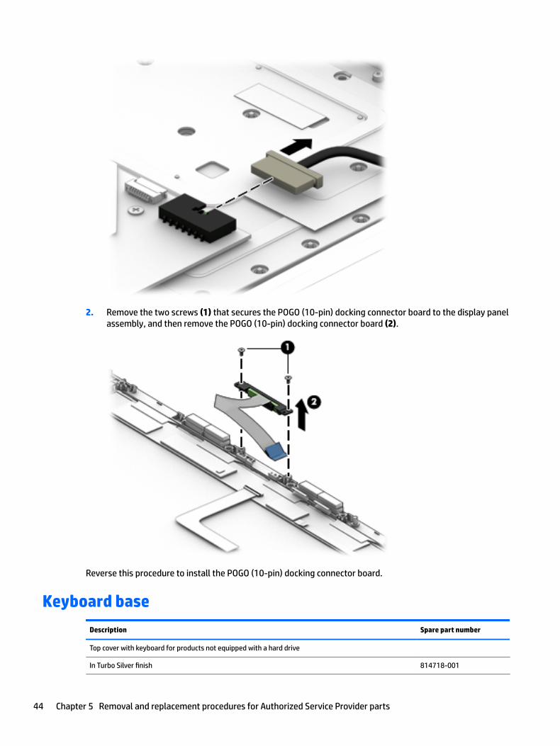
2. Remove the two screws (1) that secures the POGO (10-pin) docking connector board to the display panel assembly, and then remove the POGO (10-pin) docking connector board (2).
Reverse this procedure to install the POGO (10-pin) docking connector board.
Keyboard base
Description Spare part number
Top cover with keyboard for products not equipped with a hard drive
In Turbo Silver finish 814718-001
44 Chapter 5 Removal and replacement procedures for Authorized Service Provider parts
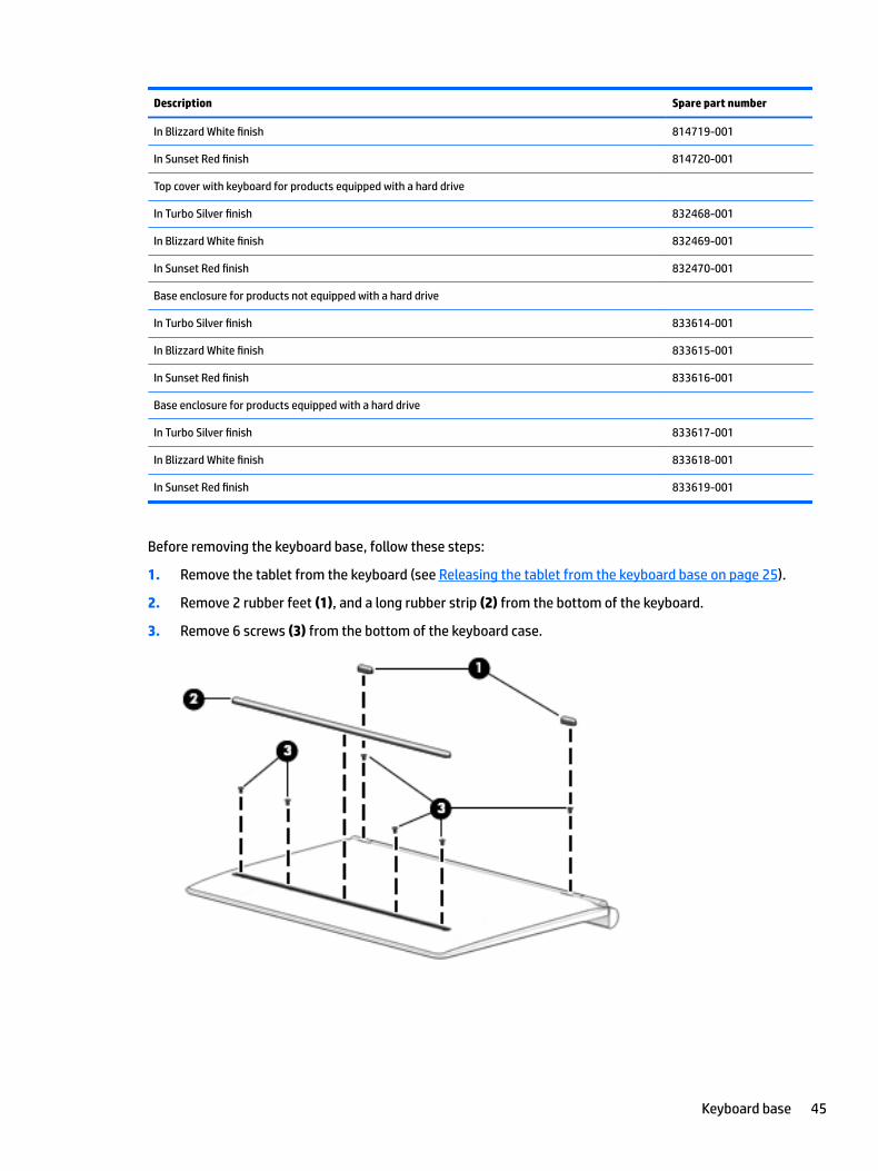
Description Spare part number
In Blizzard White finish 814719-001
In Sunset Red finish 814720-001
Top cover with keyboard for products equipped with a hard drive
In Turbo Silver finish 832468-001
In Blizzard White finish 832469-001
In Sunset Red finish 832470-001
Base enclosure for products not equipped with a hard drive
In Turbo Silver finish 833614-001
In Blizzard White finish 833615-001
In Sunset Red finish 833616-001
Base enclosure for products equipped with a hard drive
In Turbo Silver finish 833617-001
In Blizzard White finish 833618-001
In Sunset Red finish 833619-001
Before removing the keyboard base, follow these steps:
1. Remove the tablet from the keyboard (see Releasing the tablet from the keyboard base on page 25).
2. Remove 2 rubber feet (1), and a long rubber strip (2) from the bottom of the keyboard.
3. Remove 6 screws (3) from the bottom of the keyboard case.
Keyboard base 45

4. Use a nylon pry tool (1) to open the keyboard case, and then remove the bottom cover (2).
Reverse this procedure to replace the keyboard base.
Hard drive (select products only)
Description Spare part number
500 GB 5400 RPM SATA RAW 7mm hard drive 778186-005
1 TB 5400 RPM SATA RAW 7mm hard drive 762990-005
Hard drive hardware kit 833637-001
Before removing the hard drive, follow these steps:
1. Remove the tablet from the keyboard (see Releasing the tablet from the keyboard base on page 25), and then remove the following components:
▲ Keyboard base (see Keyboard base on page 44).
2. Disconnect the hard drive cable(1), and then lift the hard drive (2) to remove it.
46 Chapter 5 Removal and replacement procedures for Authorized Service Provider parts

3. Remove the hard drive connector(1), and then remove the hard drive bracket(2) from the hard drive.
Reverse this procedure to install the hard drive.
Keyboard board
Description Spare part number
Keyboard board for products not equipped with a hard drive 833627-001
833639-001
Keyboard board for products equipped with a hard drive 833628-001
Before removing the keyboard board, follow these steps:
1. Remove the tablet from the keyboard (see Releasing the tablet from the keyboard base on page 25).
2. Remove the tablet from the keyboard (see Releasing the tablet from the keyboard base on page 25), and then remove the following components:
a. Keyboard base (see Keyboard base on page 44).
b. Hard drive (see Hard drive (select products only) on page 46).
3. Disconnect the TouchPad cable(1), disconnect the keyboard cable (2), and then disconnect the POGO cable(3).
Keyboard board 47

4. Remove 2 screws (4) and (5), and then lift the keyboard board (6) to remove it.
Reverse this procedure to install the keyboard board.
TouchPad
Description Spare part number
TouchPad
In Turbo Silver 833638-001
In Blizzard White 835706-001
In Sunset Red 835707-001
Before removing the TouchPad, follow these steps:
1. Remove the tablet from the keyboard (see Releasing the tablet from the keyboard base on page 25), and then remove the following components:
a. Keyboard base (see Keyboard base on page 44).
b. Hard drive (see Hard drive (select products only) on page 46).
c. Keyboard board (see Keyboard board on page 47).
2. Release the TouchPad cable (2) from the ZIF connector (1) .
48 Chapter 5 Removal and replacement procedures for Authorized Service Provider parts

3. Remove 4 screws (3) from the TouchPad bracket, and then lift the bracket(4) to remove it.
4. Lift the TouchPad (5) to remove it.
Reverse this procedure to install the TouchPad.
Hinge cover
Description Spare part number
Hinge cover for products not equipped with a hard drive
In Turbo Silver finish 833629-001
In Blizzard White finish 833630-001
In Sunset Red finish 833631-001
Hinge cover for products equipped with a hard drive
In Turbo Silver finish 833632-001
In Blizzard White finish 833633-001
In Sunset Red finish 833634-001
Before removing the hinge cover, follow these steps:
1. Remove the tablet from the keyboard (see Releasing the tablet from the keyboard base on page 25), and then remove the following components:
a. Keyboard base (see Keyboard base on page 44).
b. Hard drive (see Hard drive (select products only) on page 46).
Hinge cover 49

c. Keyboard board (see Keyboard board on page 47).
d. TouchPad (see TouchPad on page 48).
2. Remove 3 screws from the left hinge bracket and 3 screws from the right hinge bracket (1) , and then lift the hinge brackets (2) to remove them.
3. Remove 2 screws from the left hinge and 3 screws from the right hinge (1) , and then lift the hinge cover(2) to remove it.
50 Chapter 5 Removal and replacement procedures for Authorized Service Provider parts
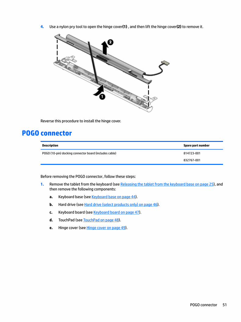
4. Use a nylon pry tool to open the hinge cover(1) , and then lift the hinge cover(2) to remove it.
Reverse this procedure to install the hinge cover.
POGO connector
Description Spare part number
POGO (10-pin) docking connector board (includes cable) 814723-001
832767-001
Before removing the POGO connector, follow these steps:
1. Remove the tablet from the keyboard (see Releasing the tablet from the keyboard base on page 25), and then remove the following components:
a. Keyboard base (see Keyboard base on page 44).
b. Hard drive (see Hard drive (select products only) on page 46).
c. Keyboard board (see Keyboard board on page 47).
d. TouchPad (see TouchPad on page 48).
e. Hinge cover (see Hinge cover on page 49).
POGO connector 51

2. Remove 2 screws from the POGO connector(1) , and then remove the POGO cable (2) to remove it.
Reverse this procedure to install the POGO connector.
52 Chapter 5 Removal and replacement procedures for Authorized Service Provider parts

6 Using Setup Utility (BIOS) in Windows 10
Setup Utility, or Basic Input/Output System (BIOS), controls communication between all the input and output devices on the system (such as disk drives, display, keyboard, mouse, and printer). Setup Utility (BIOS) includes settings for the types of devices installed, the startup sequence of the computer, and the amount of system and extended memory.
NOTE: To start Setup Utility on convertible computers, your computer must be in notebook mode and you must use the keyboard attached to your notebook. The on-screen keyboard, which displays in tablet mode, cannot access Setup Utility.
Starting Setup Utility (BIOS)CAUTION: Use extreme care when making changes in Setup Utility (BIOS). Errors can prevent the computer from operating properly.
NOTE: To start Setup Utility on convertible computers, your computer must be in notebook mode and you must use the keyboard attached to your notebook. The on-screen keyboard, which displays in tablet mode, cannot access Setup Utility.
● Computers or tablets with keyboards:
▲ Turn on or restart the computer, quickly press esc, and then press f10.
● Tablets without keyboards:
1. Turn on or restart the tablet, and then quickly hold down the volume down button.
- or -
Turn on or restart the tablet, and then quickly hold down the Windows button.
2. Tap f10.
Updating Setup Utility (BIOS)Updated versions of Setup Utility (BIOS) may be available on the HP website.
Most BIOS updates on the HP website are packaged in compressed files called SoftPaqs.
Some download packages contain a file named Readme.txt, which contains information regarding installing and troubleshooting the file.
Determining the BIOS version
To decide whether you need to update Setup Utility (BIOS), first determine the BIOS version on your computer.
To reveal the BIOS version information (also known as ROM date and System BIOS):
1. Type support in the taskbar search box, and then select the HP Support Assistant app.
– or –
Starting Setup Utility (BIOS) 53

Click the question mark icon in the taskbar.
2. Select My PC, and then select Specifications.
– or –
▲ Use Setup Utility (BIOS).
To use Setup Utility (BIOS):
1. Start Setup Utility (BIOS) (see Starting Setup Utility (BIOS) on page 53).
2. Select Main, select System Information, and then make note of the BIOS version.
3. Select Exit, select No, and then follow the on-screen instructions.
To check for later BIOS versions, see Downloading a BIOS update on page 54.
Downloading a BIOS update
CAUTION: To reduce the risk of damage to the computer or an unsuccessful installation, download and install a BIOS update only when the computer is connected to reliable external power using the AC adapter. Do not download or install a BIOS update while the computer is running on battery power, docked in an optional docking device, or connected to an optional power source. During the download and installation, follow these instructions:
● Do not disconnect power from the computer by unplugging the power cord from the AC outlet.
● Do not shut down the computer or initiate Sleep.
● Do not insert, remove, connect, or disconnect any device, cable, or cord.
NOTE: If your computer is connected to a network, consult the network administrator before installing any software updates, especially system BIOS updates.
1. Type support in the taskbar search box, and then select the HP Support Assistant app.
– or –
Click the question mark icon in the taskbar.
2. Click Updates, and then click Check for updates and messages.
3. Follow the on-screen instructions.
4. At the download area, follow these steps:
a. Identify the most recent BIOS update and compare it to the BIOS version currently installed on your computer. If the update is more recent than your BIOS version, make a note of the date, name, or other identifier. You may need this information to locate the update later, after it has been downloaded to your hard drive.
b. Follow the on-screen instructions to download your selection to the hard drive.
Make a note of the path to the location on your hard drive where the BIOS update is downloaded. You will need to access this path when you are ready to install the update.
BIOS installation procedures vary. Follow any instructions that appear on the screen after the download is complete. If no instructions appear, follow these steps:
1. Type file in the taskbar search box, and then select File Explorer.
2. Click your hard drive designation. The hard drive designation is typically Local Disk (C:).
3. Using the hard drive path you recorded earlier, open the folder that contains the update.
54 Chapter 6 Using Setup Utility (BIOS) in Windows 10

4. Double-click the file that has an .exe extension (for example, filename.exe).
The BIOS installation begins.
5. Complete the installation by following the on-screen instructions.
NOTE: After a message on the screen reports a successful installation, you can delete the downloaded file from your hard drive.
Synchronizing a tablet and keyboard (select products only)For a tablet with a detachable keyboard, when you attach the tablet to the keyboard and restart the computer, Setup Utility (BIOS) checks to see if the Embedded Controller firmware on the keyboard needs to be synchronized. If so, synchronization begins. If the synchronization is interrupted, a notification screen displays for 10 seconds before the tablet restarts and attempts to synchronize again.
NOTE: The Embedded Controller firmware will synchronize ONLY if the tablet or keyboard battery is more than 50% charged, or if your tablet is connected to AC power.
Synchronizing a tablet and keyboard (select products only) 55

7 Using HP PC Hardware Diagnostics (UEFI) in Windows 10
HP PC Hardware Diagnostics is a Unified Extensible Firmware Interface (UEFI) that allows you to run diagnostic tests to determine whether the computer hardware is functioning properly. The tool runs outside the operating system so that it can isolate hardware failures from issues that are caused by the operating system or other software components.
NOTE: To start BIOS on a convertible computer, your computer must be in notebook mode and you must use the keyboard attached to your tablet. The on-screen keyboard, which displays in tablet mode, cannot access BIOS.
To start HP PC Hardware Diagnostics UEFI:
1. Start BIOS:
● Computers or tablets with keyboards:
▲ Turn on or restart the computer, quickly press esc.
● Tablets without keyboards:
▲ Turn on or restart the tablet, and then quickly hold down the volume down button.
- or -
Turn on or restart the tablet, and then quickly hold down the Windows button.
2. Press or tap f2.
The BIOS searches three places for the diagnostic tools, in the following order:
a. Connected USB drive
NOTE: To download the HP PC Hardware Diagnostics (UEFI) tool to a USB drive, see Downloading HP PC Hardware Diagnostics (UEFI) to a USB device on page 56.
b. Hard drive
c. BIOS
3. When the diagnostic tool opens, select the type of diagnostic test you want to run, and then follow the on-screen instructions. On a tablet, press the volume down button to stop a diagnostic test.
NOTE: If you need to stop a diagnostic test on computers or tablets with a keyboard, press esc.
Downloading HP PC Hardware Diagnostics (UEFI) to a USB deviceThere are two options to download HP PC Hardware Diagnostics to a USB device:
Download the latest UEFI version:
1. Go to http://www.hp.com/go/techcenter/pcdiags. The HP PC Diagnostics home page is displayed.
2. In the HP PC Hardware Diagnostics section, click the Download link, and then select Run.
56 Chapter 7 Using HP PC Hardware Diagnostics (UEFI) in Windows 10

Download any version of UEFI for a specific product:
1. Go to http://www.hp.com/support, and then select your country. The HP Support page is displayed.
2. Click Drivers & Downloads.
3. In the text box, enter the product name, and then click Go.
– or –
Click Find Now to let HP automatically detect your product.
4. Select your computer, and then select your operating system.
5. In the Diagnostic section, follow the on-screen instructions to select and download the UEFI version you want.
Downloading HP PC Hardware Diagnostics (UEFI) to a USB device 57

8 Using Setup Utility (BIOS) and HP PC Hardware Diagnostics (UEFI) in Windows 8.1
Setup Utility, or Basic Input/Output System (BIOS), controls communication between all the input and output devices on the system (such as disk drives, display, keyboard, mouse, and printer). Setup Utility (BIOS) includes settings for the types of devices installed, the startup sequence of the tablet, and the amount of system and extended memory.
Starting Setup Utility (BIOS)CAUTION: Use extreme care when making changes in Setup Utility (BIOS). Errors can prevent the computer from operating properly.
NOTE: To start Setup Utility, your computer must be in notebook mode and you must use the keyboard attached to your notebook. The on-screen keyboard, which displays in tablet mode, cannot access Setup Utility.
● Computers or tablets with keyboards:
▲ Turn on or restart the computer, quickly press esc, and then press f10.
● Tablets without keyboards:
1. Turn on or restart the tablet, and then quickly hold down the volume down button.
2. Tap f10.
Updating Setup Utility (BIOS)Updated versions of Setup Utility (BIOS) may be available on the HP website.
Most BIOS updates on the HP website are packaged in compressed files called SoftPaqs.
Some download packages contain a file named Readme.txt, which contains information regarding installing and troubleshooting the file.
Determining the BIOS version
To decide whether you need to update Setup Utility (BIOS), first determine the BIOS version on your computer.
BIOS version information (also known as ROM date and System BIOS) can be accessed from the Start screen by typing support, selecting the HP Support Assistant app, selecting My computer, and then selecting System Information, or by using Setup Utility (BIOS).
To use Setup Utility (BIOS):
1. Start Setup Utility (BIOS) (see Starting Setup Utility (BIOS) on page 58).
2. Select Main, and then make note of the BIOS version.
3. Select Exit, select Exit Discarding Changes, and then follow the on-screen instructions.
To check for later BIOS versions, see Downloading a BIOS update on page 54.
58 Chapter 8 Using Setup Utility (BIOS) and HP PC Hardware Diagnostics (UEFI) in Windows 8.1

Downloading a BIOS update
CAUTION: To reduce the risk of damage to the computer or an unsuccessful installation, download and install a BIOS update only when the computer is connected to reliable external power using the AC adapter. Do not download or install a BIOS update while the computer is running on battery power, docked in an optional docking device, or connected to an optional power source. During the download and installation, follow these instructions:
● Do not disconnect power from the computer by unplugging the power cord from the AC outlet.
● Do not shut down the computer or initiate Sleep.
● Do not insert, remove, connect, or disconnect any device, cable, or cord.
NOTE: If your computer is connected to a network, consult the network administrator before installing any software updates, especially system BIOS updates.
1. From the Start screen, type support, and then select the HP Support Assistant app.
– or –
From the Windows desktop, select the question mark icon in the taskbar.
2. Select Updates and tune-ups, and then select Check for HP updates now.
3. Follow the on-screen instructions.
4. At the download area, follow these steps:
a. Identify the most recent BIOS update and compare it to the BIOS version currently installed on your computer. If the update is more recent than your BIOS version, make a note of the date, name, or other identifier. You may need this information to locate the update later, after it has been downloaded to your hard drive.
b. Follow the on-screen instructions to download your selection to the hard drive.
Make a note of the path to the location on your hard drive where the BIOS update is downloaded. You will need to access this path when you are ready to install the update.
BIOS installation procedures vary. Follow any instructions that appear on the screen after the download is complete. If no instructions appear, follow these steps:
1. From the Start screen, type file, and then select File Explorer.
– or –
From the Windows desktop, right-click or tap and hold the Start button, and then select File Explorer.
2. Select your hard drive designation. The hard drive designation is typically Local Disk (C:).
3. Using the hard drive path you recorded earlier, open the folder that contains the update.
4. Double-click or double-tap the file that has an .exe extension (for example, filename.exe).
The BIOS installation begins.
5. Complete the installation by following the on-screen instructions.
NOTE: After a message on the screen reports a successful installation, you can delete the downloaded file from your hard drive.
Updating Setup Utility (BIOS) 59

Using HP PC Hardware Diagnostics (UEFI)HP PC Hardware Diagnostics is a Unified Extensible Firmware Interface (UEFI) that allows you to run diagnostic tests to determine whether the computer hardware is functioning properly. The tool runs outside the operating system so that it can isolate hardware failures from issues that are caused by the operating system or other software components.
NOTE: To start Setup Utility, your computer must be in notebook mode and you must use the keyboard attached to your tablet. The on-screen keyboard, which displays in tablet mode, cannot access Setup Utility.
To start HP PC Hardware Diagnostics (UEFI):
1. Start Setup Utility:
● Computers or tablets with keyboards:
▲ Turn on or restart the computer, quickly press esc.
● Tablets without keyboards:
▲ Turn on or restart the tablet, and then quickly hold down the volume down button.
2. Press or tap f2.
The BIOS searches three places for the diagnostic tools, in the following order:
a. Connected USB drive
NOTE: To download the HP PC Hardware Diagnostics (UEFI) tool to a USB drive, see Downloading HP PC Hardware Diagnostics (UEFI) to a USB device on page 60.
b. Hard drive
c. Setup Utility (BIOS)
3. When the diagnostic tool opens, use the keyboard arrow keys to select the type of diagnostic test you want to run, and then follow the on-screen instructions.
NOTE: If you need to stop a diagnostic test, press or tap esc.
Downloading HP PC Hardware Diagnostics (UEFI) to a USB device
There are two options to download HP PC Hardware Diagnostics to a USB device.
Download the latest UEFI version:
1. Go to http://www.hp.com/go/techcenter/pcdiags. The HP PC Diagnostics home page is displayed.
2. In the HP PC Hardware Diagnostics section, select the Download link, and then select Run.
Download any version of UEFI for a specific product:
1. Go to http://www.hp.com/support, and then select your country. The HP Support page is displayed.
2. Select Drivers & Downloads.
3. In the text box, enter the product name, and then select Go.
– or –
Select Find now to let HP automatically detect your product.
60 Chapter 8 Using Setup Utility (BIOS) and HP PC Hardware Diagnostics (UEFI) in Windows 8.1

4. Select your computer model, and then select your operating system.
5. In the Diagnostic section, follow the on-screen instructions to select and download the UEFI version you want.
Using HP PC Hardware Diagnostics (UEFI) 61
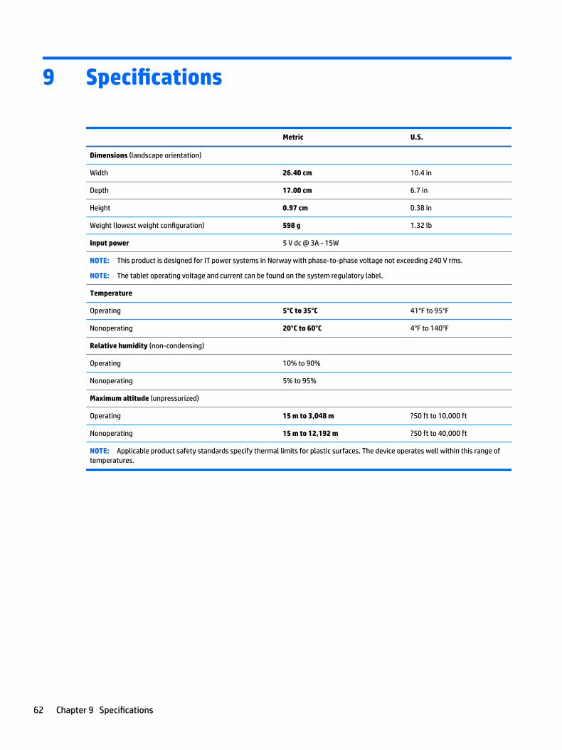
9 Specifications
Metric U.S.
Dimensions (landscape orientation)
Width 26.40 cm 10.4 in
Depth 17.00 cm 6.7 in
Height 0.97 cm 0.38 in
Weight (lowest weight configuration) 598 g 1.32 lb
Input power 5 V dc @ 3A - 15W
NOTE: This product is designed for IT power systems in Norway with phase-to-phase voltage not exceeding 240 V rms.
NOTE: The tablet operating voltage and current can be found on the system regulatory label.
Temperature
Operating 5°C to 35°C 41°F to 95°F
Nonoperating 20°C to 60°C 4°F to 140°F
Relative humidity (non-condensing)
Operating 10% to 90%
Nonoperating 5% to 95%
Maximum altitude (unpressurized)
Operating 15 m to 3,048 m ?50 ft to 10,000 ft
Nonoperating 15 m to 12,192 m ?50 ft to 40,000 ft
NOTE: Applicable product safety standards specify thermal limits for plastic surfaces. The device operates well within this range of temperatures.
62 Chapter 9 Specifications

10 Backing up, restoring, and recovering in Windows 10
This chapter provides information about the following processes. The information in the chapter is standard procedure for most products.
● Creating recovery media and backups
● Restoring and recovering your system
For additional information, refer to the HP support assistant app.
▲ Type support in the taskbar search box, and then select the HP Support Assistant app.
‒ or –
Click the question mark icon in the taskbar.
IMPORTANT: If you will be performing recovery procedures on a tablet, the tablet battery must be at least 70% charged before you start the recovery process.
IMPORTANT: For a tablet with a detachable keyboard, connect the keyboard to the keyboard dock before beginning any recovery process.
Creating recovery media and backupsThe following methods of creating recovery media and backups are available on select products only. Choose the available method according to your computer model.
● Use HP Recovery Manager to create HP Recovery media after you successfully set up the computer. This step creates a backup of the HP Recovery partition on the computer. The backup can be used to reinstall the original operating system in cases where the hard drive is corrupted or has been replaced. For information on creating recovery media, see Creating HP Recovery media (select products only) on page 63. For information on the recovery options that are available using the recovery media, see Using Windows tools on page 64.
● Use Windows tools to create system restore points and create backups of personal information.
For more information, see Recovering using HP Recovery Manager on page 65.
NOTE: If storage is 32 GB or less, Microsoft System Restore is disabled by default.
Creating HP Recovery media (select products only)
If possible, check for the presence of the Recovery partition and the Windows partition. From the Start menu, select File Explorer, and then select This PC.
● If your computer does not list the Windows partition and the Recovery partition, you can obtain recovery media for your system from support. See the Worldwide Telephone Numbers booklet included with the computer. You can also find contact information on the HP website. Go to http://www.hp.com/support, select your country or region, and follow the on-screen instructions.
Creating recovery media and backups 63

You can use Windows tools to create system restore points and create backups of personal information, see Using Windows tools on page 64.
● If your computer does list the Recovery partition and the Windows partition, you can use HP Recovery Manager to create recovery media after you successfully set up the computer. HP Recovery media can be used to perform system recovery if the hard drive becomes corrupted. System recovery reinstalls the original operating system and software programs that were installed at the factory and then configures the settings for the programs. HP Recovery media can also be used to customize the system or restore the factory image if you replace the hard drive.
◦ Only one set of recovery media can be created. Handle these recovery tools carefully, and keep them in a safe place.
◦ HP Recovery Manager examines the computer and determines the required storage capacity for the media that will be required.
◦ To create recovery discs, your computer must have an optical drive with DVD writer capability, and you must use only high-quality blank DVD-R, DVD+R, DVD-R DL, or DVD+R DL discs. Do not use rewritable discs such as CD±RW, DVD±RW, double-layer DVD±RW, or BD-RE (rewritable Blu-ray) discs; they are not compatible with HP Recovery Manager software. Or, instead, you can use a high-quality blank USB flash drive.
◦ If your computer does not include an integrated optical drive with DVD writer capability, but you would like to create DVD recovery media, you can use an external optical drive (purchased separately) to create recovery discs. If you use an external optical drive, it must be connected directly to a USB port on the computer; the drive cannot be connected to a USB port on an external device, such as a USB hub. If you cannot create DVD media yourself, you can obtain recovery discs for your computer from HP. See the Worldwide Telephone Numbers booklet included with the computer. You can also find contact information on the HP website. Go to http://www.hp.com/support, select your country or region, and follow the on-screen instructions.
◦ Be sure that the computer is connected to AC power before you begin creating the recovery media.
◦ The creation process can take an hour or more. Do not interrupt the creation process.
◦ If necessary, you can exit the program before you have finished creating all of the recovery DVDs. HP Recovery Manager will finish burning the current DVD. The next time you start HP Recovery Manager, you will be prompted to continue.
To create HP Recovery media:
IMPORTANT: For a tablet with a detachable keyboard, connect the keyboard to the keyboard dock before beginning these steps.
1. Type recovery in the taskbar search box, and then select HP Recovery Manager.
2. Select Create recovery media, and then follow the on-screen instructions.
If you ever need to recover the system, see Recovering using HP Recovery Manager on page 65.
Using Windows toolsYou can create recovery media, system restore points, and backups of personal information using Windows tools.
NOTE: If storage is 32 GB or less, Microsoft System Restore is disabled by default.
For more information and steps, see the Get started app.
▲ Select the Start button, and then select the Get started app.
64 Chapter 10 Backing up, restoring, and recovering in Windows 10

Restore and recoveryThere are several options for recovering your system. Choose the method that best matches your situation and level of expertise:
IMPORTANT: Not all methods are available on all products.
● Windows offers several options for restoring from backup, refreshing the computer, and resetting the computer to its original state. For more information see the Get started app.
▲ Select the Start button, and then select the Get started app.
● If you need to correct a problem with a preinstalled application or driver, use the Reinstall drivers and/or applications option (select products only) of HP Recovery Manager to reinstall the individual application or driver.
▲ Type recovery in the taskbar search box, select HP Recovery Manager, select Reinstall drivers and/or applications, and then follow the on-screen instructions.
● If you want to recover the Windows partition to original factory content, you can choose the System Recovery option from the HP Recovery partition (select products only) or use the HP Recovery media. For more information, see Recovering using HP Recovery Manager on page 65. If you have not already created recovery media, see Creating HP Recovery media (select products only) on page 63.
● On select products, if you want to recover the computer's original factory partition and content, or if you have replaced the hard drive, you can use the Factory Reset option of HP Recovery media. For more information, see Recovering using HP Recovery Manager on page 65.
● On select products, if you want to remove the recovery partition to reclaim hard drive space, HP Recovery Manager offers the Remove Recovery Partition option.
For more information, see Removing the HP Recovery partition (select products only) on page 68.
Recovering using HP Recovery Manager
HP Recovery Manager software allows you to recover the computer to its original factory state by using the HP Recovery media that you either created or that you obtained from HP, or by using the HP Recovery partition (select products only). If you have not already created recovery media, see Creating HP Recovery media (select products only) on page 63.
What you need to know before you get started
● HP Recovery Manager recovers only software that was installed at the factory. For software not provided with this computer, you must either download the software from the manufacturer's website or reinstall the software from the media provided by the manufacturer.
IMPORTANT: Recovery through HP Recovery Manager should be used as a final attempt to correct computer issues.
● HP Recovery media must be used if the computer hard drive fails. If you have not already created recovery media, see Creating HP Recovery media (select products only) on page 63.
● To use the Factory Reset option (select products only), you must use HP Recovery media. If you have not already created recovery media, see Creating HP Recovery media (select products only) on page 63.
● If your computer does not allow the creation of HP Recovery media or if the HP Recovery media does not work, you can obtain recovery media for your system from support. See the Worldwide Telephone Numbers booklet included with the computer. You can also find contact information from the HP
Restore and recovery 65
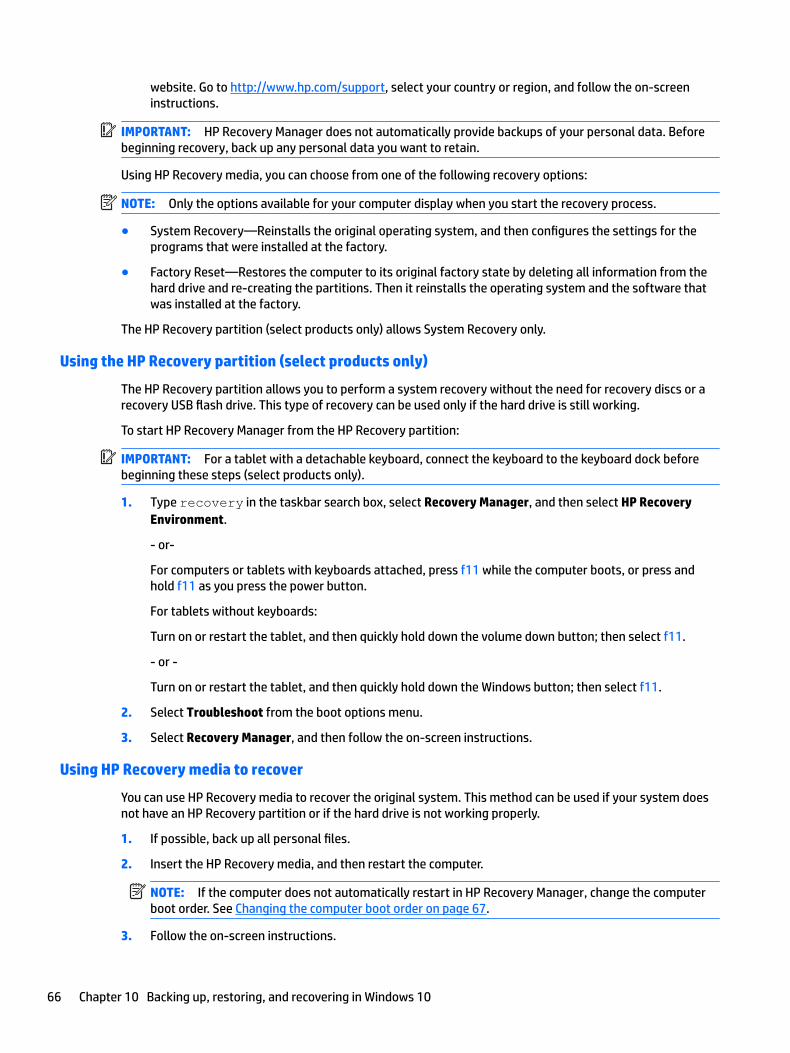
website. Go to http://www.hp.com/support, select your country or region, and follow the on-screen instructions.
IMPORTANT: HP Recovery Manager does not automatically provide backups of your personal data. Before beginning recovery, back up any personal data you want to retain.
Using HP Recovery media, you can choose from one of the following recovery options:
NOTE: Only the options available for your computer display when you start the recovery process.
● System Recovery—Reinstalls the original operating system, and then configures the settings for the programs that were installed at the factory.
● Factory Reset—Restores the computer to its original factory state by deleting all information from the hard drive and re-creating the partitions. Then it reinstalls the operating system and the software that was installed at the factory.
The HP Recovery partition (select products only) allows System Recovery only.
Using the HP Recovery partition (select products only)
The HP Recovery partition allows you to perform a system recovery without the need for recovery discs or a recovery USB flash drive. This type of recovery can be used only if the hard drive is still working.
To start HP Recovery Manager from the HP Recovery partition:
IMPORTANT: For a tablet with a detachable keyboard, connect the keyboard to the keyboard dock before beginning these steps (select products only).
1. Type recovery in the taskbar search box, select Recovery Manager, and then select HP Recovery Environment.
- or-
For computers or tablets with keyboards attached, press f11 while the computer boots, or press and hold f11 as you press the power button.
For tablets without keyboards:
Turn on or restart the tablet, and then quickly hold down the volume down button; then select f11.
- or -
Turn on or restart the tablet, and then quickly hold down the Windows button; then select f11.
2. Select Troubleshoot from the boot options menu.
3. Select Recovery Manager, and then follow the on-screen instructions.
Using HP Recovery media to recover
You can use HP Recovery media to recover the original system. This method can be used if your system does not have an HP Recovery partition or if the hard drive is not working properly.
1. If possible, back up all personal files.
2. Insert the HP Recovery media, and then restart the computer.
NOTE: If the computer does not automatically restart in HP Recovery Manager, change the computer boot order. See Changing the computer boot order on page 67.
3. Follow the on-screen instructions.
66 Chapter 10 Backing up, restoring, and recovering in Windows 10

Changing the computer boot order
If your computer does not restart in HP Recovery Manager, you can change the computer boot order, which is the order of devices listed in BIOS where the computer looks for startup information. You can change the selection to an optical drive or a USB flash drive.
To change the boot order:
IMPORTANT: For a tablet with a detachable keyboard, connect the keyboard to the keyboard dock before beginning these steps.
1. Insert the HP Recovery media.
2. Access BIOS:
For computers or tablets with keyboards attached:
▲ Turn on or restart the computer or tablet, quickly press esc, and then press f9 for boot options.
For tablets without keyboards:
▲ Turn on or restart the tablet, and then quickly hold down the volume down button; then select f9.
- or -
Turn on or restart the tablet, and then quickly hold down the Windows button; then select f9.
3. Select the optical drive or USB flash drive from which you want to boot.
4. Follow the on-screen instructions.
Restore and recovery 67

Removing the HP Recovery partition (select products only)
HP Recovery Manager software allows you to remove the HP Recovery partition to free up hard drive space.
IMPORTANT: After you remove the HP Recovery partition, you will not be able to perform System Recovery or create HP recovery media from the HP Recovery partition. So before you remove the Recovery partition, create HP Recovery media; see Creating HP Recovery media (select products only) on page 63.
NOTE: The Remove Recovery Partition option is only available on products that support this function.
Follow these steps to remove the HP Recovery partition:
1. Type recovery in the taskbar search box, and then select HP Recovery Manager.
2. Select Remove Recovery Partition, and then follow the on-screen instructions.
68 Chapter 10 Backing up, restoring, and recovering in Windows 10
11 Backing up, restoring, and recovering in Windows 8.1
This chapter provides information about the following processes. The information in the chapter is standard procedure for most products.
● Creating recovery media and backups
● Restoring and recovering your system
For additional information, refer to Help and Support.
▲ From the Start screen, type help, and then select Help and Support.
IMPORTANT: If you will be using F11 startup recovery or USB media recovery to recover your system, the tablet battery must be at least 70% charged before you start the recovery process.
Creating recovery media and backupsThe following methods of creating recovery media and backups are available on select products only. Choose the available method according to your computer model.
● Use HP Recovery Manager to create HP Recovery media after you successfully set up the computer. This step creates a backup of the HP Recovery partition on the computer. The backup can be used to reinstall the original operating system in cases where the hard drive is corrupted or has been replaced. For information on creating recovery media, see Recovering using HP Recovery Manager on page 71. For information on the recovery options that are available using the recovery media, see Recovering using HP Recovery Manager on page 65.
● Use Windows tools to create system restore points and create backups of personal information.
For more information, see Creating HP Recovery media (select products only) on page 69.
NOTE: If storage is 32 GB or less, Microsoft System Restore is disabled by default.
Creating HP Recovery media (select products only)
IMPORTANT: If your computer does not list a Create recovery media option, you can obtain recovery media for your system from HP. See the Worldwide Telephone Numbers booklet included with the computer. You can also find contact information on the HP website. Go to http://www.hp.com/support, select your country or region, and follow the on-screen instructions.
HP Recovery Manager is a software program that allows you to create recovery media (using either a flash drive or a set of DVDs) after you successfully set up the computer. HP Recovery media can be used to perform system recovery if the hard drive becomes corrupted. System recovery reinstalls the original operating system and software programs that were installed at the factory and then configures the settings for the programs. HP Recovery media can also be used to customize the system or restore the factory image if you replace the hard drive.
Creating recovery media and backups 69

● Only one set of recovery media can be created. Handle these recovery tools carefully, and keep them in a safe place.
● HP Recovery Manager examines the computer and determines the required storage capacity for the media that will be required.
● To create recovery discs, your computer must have an optical drive with DVD writer capability, and you must use only high-quality blank DVD-R, DVD+R, DVD-R DL, or DVD+R DL discs. Do not use rewritable discs such as CD±RW, DVD±RW, double-layer DVD±RW, or BD-RE (rewritable Blu-ray) discs; they are not compatible with HP Recovery Manager software. Or, instead, you can use a high-quality blank USB flash drive.
● If your computer does not include an integrated optical drive with DVD writer capability, but you would like to create DVD recovery media, you can use an external optical drive (purchased separately) to create recovery discs. If you use an external optical drive, it must be connected directly to a USB port on the computer; the drive cannot be connected to a USB port on an external device, such as a USB hub. If you cannot create DVD media yourself, you can obtain recovery discs for your computer from HP. See the Worldwide Telephone Numbers booklet included with the computer. You can also find contact information on the HP website. Go to http://www.hp.com/support, select your country or region, and follow the on-screen instructions.
● Be sure that the computer is connected to AC power before you begin creating the recovery media.
● The creation process can take an hour or more. Do not interrupt the creation process.
● If necessary, you can exit the program before you have finished creating all of the recovery DVDs. HP Recovery Manager will finish burning the current DVD. The next time you start HP Recovery Manager, you will be prompted to continue.
To create HP Recovery media:
IMPORTANT: For tablets with a detachable keyboard, connect the tablet to the keyboard base before beginning these steps.
1. From the Start screen, type recovery, and then select HP Recovery Manager.
2. Select Create recovery media, and then follow the on-screen instructions.
If you ever need to recover the system, see Recovering using HP Recovery Manager on page 65.
Using Windows toolsYou can use Windows tools to create system restore points and create backups of personal information.
NOTE: If storage is 32 GB or less, Microsoft System Restore is disabled by default.
For more information and steps, see Help and Support.
▲ From the Start screen, type help, and then select Help and Support.
Restore and recoveryThere are several options for recovering your system. Choose the method that best matches your situation and level of expertise:
IMPORTANT: Not all methods are available on all products.
● Windows offers several options for restoring from backup, refreshing the computer, and resetting the computer to its original state. For more information see Help and Support.
70 Chapter 11 Backing up, restoring, and recovering in Windows 8.1

▲ From the Start screen, type help, and then select Help and Support.
● On select products, if you need to correct a problem with a preinstalled application or driver, use the Reinstall drivers and/or applications option of HP Recovery Manager to reinstall the individual application or driver.
▲ From the Start screen, type recovery, select HP Recovery Manager, select Reinstall drivers and/or applications, and then follow the on-screen instructions.
● On select products, if you want to reset your computer using a minimized image, you can choose the HP Minimized Image Recovery option from the HP Recovery partition or HP Recovery media. Minimized Image Recovery installs only drivers and hardware-enabling applications. Other applications included in the image continue to be available for installation through the Reinstall drivers and/or applications option in HP Recovery Manager.
For more information, see Recovering using HP Recovery Manager on page 65.
● If you want to recover the Windows partition to original factory content, you can choose the System Recovery option from the HP Recovery partition (select products only) or use the HP Recovery media. For more information, see Recovering using HP Recovery Manager on page 65. If you have not already created recovery media, see Creating HP Recovery media (select products only) on page 63.
● On select products, if you want to recover the computer's original factory partition and content, or if you have replaced the hard drive, you can use the Factory Reset option of HP Recovery media. For more information, see Recovering using HP Recovery Manager on page 65.
● On select products, if you want to remove the recovery partition to reclaim hard drive space, HP Recovery Manager offers the Remove Recovery Partition option.
For more information, see Removing the HP Recovery partition (select products only) on page 73.
Recovering using HP Recovery Manager
HP Recovery Manager software allows you to recover the computer to its original factory state by using the HP Recovery media that you either created or that you obtained from HP, or by using the HP Recovery partition (select products only). If you have not already created recovery media, see Creating HP Recovery media (select products only) on page 63.
What you need to know before you get started
● HP Recovery Manager recovers only software that was installed at the factory. For software not provided with this computer, you must either download the software from the manufacturer's website or reinstall the software from the media provided by the manufacturer.
IMPORTANT: Recovery through HP Recovery Manager should be used as a final attempt to correct computer issues.
● HP Recovery media must be used if the computer hard drive fails. If you have not already created recovery media, see Creating HP Recovery media (select products only) on page 63.
● To use the Factory Reset option (select products only), you must use HP Recovery media. If you have not already created recovery media, see Creating HP Recovery media (select products only) on page 63.
● If your computer does not allow the creation of HP Recovery media or if the HP Recovery media does not work, you can obtain recovery media for your system from support. See the Worldwide Telephone Numbers booklet included with the computer. You can also find contact information from the HP website. Go to http://www.hp.com/support, select your country or region, and follow the on-screen instructions.
Restore and recovery 71

IMPORTANT: HP Recovery Manager does not automatically provide backups of your personal data. Before beginning recovery, back up any personal data you want to retain.
Using HP Recovery media, you can choose from one of the following recovery options:
NOTE: Only the options available for your computer display when you start the recovery process.
● System Recovery Reinstalls the original operating system, and then configures the settings for the programs that were installed at the factory.
● Minimized Image Recovery (select products only) Reinstalls the operating system and all hardware-related drivers and software, but not other software applications.
● Factory Reset Restores the computer to its original factory state by deleting all information from the hard drive and re-creating the partitions. Then it reinstalls the operating system and the software that was installed at the factory.
The HP Recovery partition (select products only) allows System Recovery and, on select products, Minimized Image Recovery.
Using the HP Recovery partition (select products only)
The HP Recovery partition allows you to perform a system recovery or, on select products, minimized image recovery without the need for recovery discs or a recovery USB flash drive. This type of recovery can be used only if the hard drive is still working.
To start HP Recovery Manager from the HP Recovery partition:
IMPORTANT: For tablets with a detachable keyboard, connect the tablet to the keyboard base before beginning these steps (select products only).
1. From the Start screen, type recovery, select HP Recovery Manager, and then select HP Recovery Environment.
- or-
Press f11 while the computer boots, or press and hold f11 as you press the power button.
2. Select Troubleshoot from the boot options menu.
3. Select Recovery Manager, and then follow the on-screen instructions.
Using HP Recovery media to recover
You can use HP Recovery media to recover the original system. This method can be used if your system does not have an HP Recovery partition or if the hard drive is not working properly.
1. If possible, back up all personal files.
2. Insert the HP Recovery media, and then restart the computer.
NOTE: If the computer does not automatically restart in HP Recovery Manager, change the computer boot order. See Changing the computer boot order on page 72.
3. Follow the on-screen instructions.
Changing the computer boot order
If your computer does not restart in HP Recovery Manager, you can change the computer boot order, which is the order of devices listed in BIOS where the computer looks for startup information. You can change the selection to an optical drive or a USB flash drive.
72 Chapter 11 Backing up, restoring, and recovering in Windows 8.1

To change the boot order:
IMPORTANT: For a tablet with a detachable keyboard, connect the tablet to the keyboard base before beginning these steps.
1. Insert the HP Recovery media.
2. Start Computer Setup:
For computers or tablets with keyboards attached:
▲ Turn on or restart the computer or tablet, quickly press esc, and then press f9 for boot options.
For computers or tablets without keyboards attached:
▲ Turn on or restart the computer, quickly press the volume down button, and then tap f9 for boot options.
- or -
Turn on or restart the computer, quickly press the Windows button, and then tap f9 for boot options.
3. Select the optical drive or USB flash drive from which you want to boot.
4. Follow the on-screen instructions.
Removing the HP Recovery partition (select products only)
HP Recovery Manager software allows you to remove the HP Recovery partition to free up hard drive space.
IMPORTANT: After you remove the HP Recovery partition, you can no longer use the Windows Refresh option or the Windows option to remove everything and reinstall Windows. In addition, you will not be able to perform System Recovery or Minimized Image Recovery from the HP Recovery partition. So before you remove the Recovery partition, create HP Recovery media; see Creating HP Recovery media (select products only) on page 63.
Follow these steps to remove the HP Recovery partition:
1. From the Start screen, type recovery, and then select HP Recovery Manager.
2. Select Remove Recovery Partition, and then follow the on-screen instructions.
Restore and recovery 73
12 Power cord set requirements
The wide-range input feature of the computer permits it to operate from any line voltage from 100 to 120 V ac, or from 220 to 240 V ac.
The 3-conductor power cord set included with the computer meets the requirements for use in the country or region where the equipment is purchased.
Power cord sets for use in other countries or regions must meet the requirements of thecountry and region where the computer is used.
Requirements for all countriesThe following requirements are applicable to all countries and regions:
● The length of the power cord set must be at least 1.0 m (3.3 ft) and no more than 2.0 m (6.5 ft).
● All power cord sets must be approved by an acceptable accredited agency responsible for evaluation in thecountry or region where the power cord set will be used.
● The power cord sets must have a minimum current capacity of 10 A and a nominal voltage rating of 125 or 250 V ac, as required by the power system of each country or region.
● The appliance coupler must meet the mechanical configuration of an EN 60 320/IEC 320 Standard Sheet C13 connector for mating with the appliance inlet on the back of the computer.
74 Chapter 12 Power cord set requirements

Requirements for specific countries and regions
Country/region Accredited agency Applicable note number
Argentina IRAM 1
Australia SAA 1
Austria OVE 1
Belgium CEBEC 1
Brazil ABNT 1
Canada CSA 2
Chile IMQ 1
Denmark DEMKO 1
Finland FIMKO 1
France UTE 1
Germany VDE 1
India ISI 1
Israel SII 1
Italy IMQ 1
Japan JIS 3
The Netherlands KEMA 1
New Zealand SANZ 1
Norway NEMKO 1
The People's Republic of China CCC 4
Saudi Arabia SASO 7
Singapore PSB 1
South Africa SABS 1
South Korea KTL 5
Sweden SEMKO 1
Switzerland SEV 1
Taiwan BSMI 6
Thailand TISI 1
The United Kingdom ASTA 1
The United States UL 2
1. The flexible cord must be Type HO5VV-F, 3-conductor, 0.75 mm² conductor size. Power cord set fittings (appliance coupler and wall plug) must bear thecertification mark of the agency responsible for evaluation in thecountry or region where it will be used.
Requirements for specific countries and regions 75

Country/region Accredited agency Applicable note number
2. The flexible cord must be Type SVT/SJT or equivalent, No. 18 AWG, 3-conductor. The wall plug must be a two-pole grounding type with a NEMA 5-15P (15 A, 125 V ac) or NEMA 6-15P (15 A, 250 V ac) configuration. CSA or C-UL mark. UL file number must be on each element.
3. The appliance coupler, flexible cord, and wall plug must bear a “T” mark and registration number in accordance with the Japanese Dentori Law. The flexible cord must be Type VCTF, 3-conductor, 0.75 mm² or 1.25 mm² conductor size. The wall plug must be a two-pole grounding type with a Japanese Industrial Standard C8303 (7 A, 125 V ac) configuration.
4. The flexible cord must be Type RVV, 3-conductor, 0.75 mm² conductor size. Power cord set fittings (appliance coupler and wall plug) must bear the CCC certification mark.
5. The flexible cord must be Type H05VV-F 3-conductor, 0.75 mm² conductor size. KTL logo and individual approval number must be on each element. Corset approval number and logo must be printed on a flag label.
6. The flexible cord must be Type HVCTF 3-conductor, 1.25 mm² conductor size. Power cord set fittings (appliance coupler, cable, and wall plug) must bear the BSMI certification mark.
7. For 127 V ac, the flexible cord must be Type SVT or SJT 3-conductor, 18 AWG, with plug NEMA 5-15P (15 A, 125 V ac), with UL and CSA or C-UL marks. For 240 V ac, the flexible cord must be Type H05VV-F 3-conductor, 0.75 mm² or 1.00 mm2 conductor size, with plug BS 1363/A with BSI or ASTA marks.
76 Chapter 12 Power cord set requirements

13 Recycling
When a non-rechargeable or rechargeable battery has reached the end of its useful life, do not dispose of the battery in general household waste. Follow the local laws and regulations in your area for battery disposal.
HP encourages customers to recycle used electronic hardware, HP original print cartridges, and rechargeable batteries. For more information about recycling programs, see the HP Web site at http://www.hp.com/recycle.
77
Index
AAC adapter, spare part number 12,
13AC adapter/battery 3ambient light sensor, identifying 5antenna
spare part number 15, 19antenna, spare part number 10audio board
removal 30spare part number 10, 15, 19,
30audio, product description 1audio-out (headphone)/audio-in
(microphone) jack, identifying 4
Bback cover
removal 26spare part number 13, 19, 26spare part numbers 11
backups 63, 69base enclosure
spare part number 12, 19, 45battery
removal 28spare part number 10, 13, 28
BIOSdetermining version 53, 58downloading an update 54, 59starting the Setup Utility 53, 58updating 53, 58
boot orderchanging 67, 72
buttonspower 6volume 3Windows 3
Ccables, service considerations 21case
spare part number 20case, spare part number 12
componentsbottom edge 6display 5left side 4right side 3top edge 6
connectors, service considerations21
DDisplay cable
spare part number 11display cable 27
spare part number 13, 19display panel assembly
spare part number 9display panel assembly, spare part
number 15, 16, 26display panel, product description 1docking port, identifying 6duck head adapter, spare part
numbers 12, 16
Eelectrostatic discharge 22equipment guidelines 24external expansion, product
description 1
Ggraphics, product description 1grounding guidelines 22guidelines
equipment 24grounding 22packaging 23transporting 23workstation 23
Hhard drive
removing 46spare part number 12
hard drive hardware kitspare part number 20, 46
hard drive, spare part number 13HDMI port
identifying 3Hinge
spare part number 11, 20hinge connector
spare part number 11Hinge cover
spare part number 11, 20, 49hinge cover
removing 49HP PC Hardware Diagnostics (UEFI)
downloading 60using 56
HP Recovery Managercorrecting boot problems 67, 72starting 66, 72
HP Recovery mediacreating 63, 69recovery 66, 72
HP Recovery partitionrecovery 66, 72removing 68, 73
HP Stereo 3.5mm headsetspare part number 12, 20
Iinternal microphones, identifying 6
Jjacks
audio-out (headphone)/audio-in (microphone) 4
Kkeyboard
product description 2spare part numbers 11, 13, 14,
15, 16, 17, 18, 19keyboard base
opening 44releasing 25
Keyboard boardremoving 47spare part number 20
78 Index
keyboard boardspare part number 12, 20
Llights
AC adapter and battery 3
Mmagnetic latches, identifying 6mass storage device, product
description 1memory card reader, identifying 3memory card, identifying 3memory module, product
description 1microphone
product description 1middle frame
removal 42spare part number 10, 42
minimized image recovery 66, 72minimized image, creating 65, 71model name 1
Ooperating system, product
description 2original system recovery 65, 71
Ppackaging guidelines 23plastic parts, service
considerations 21POGO (10-pin) docking connector
boardspare part number 10
POGO (10-pin) docking connector cable
removal 43spare part number 43
POGO connectorremoving 51
POGO connector boardspare part number 15, 19, 20,
43ports
HDMI 3product description 1USB 3.0 4
power button boardspare part number 15, 19
power button, identifying 6power cord
requirements for all countries74
requirements for specific countries and regions 75
set requirements 74power requirements, product
description 2power/volume button board
removal 38spare part number 10, 38
processor, product description 1product description
audio 1display panel 1external expansion 1graphics 1keyboard 2mass storage 1memory module 1microphone 1operating system 2ports 1power requirements 2processors 1product name 1sensor 1serviceability 2video 1wireless networking 1
product name 1
Rrecover
options 65, 70recovery
discs 64, 66, 70, 72HP Recovery Manager 65, 71media 66, 72starting 66, 72supported discs 64, 70system 65, 71USB flash drive 66, 72using HP Recovery media 64, 70
recovery mediacreating 63, 69creating using HP Recovery
Manager 64, 70
recovery partitionremoving 68, 73
Rubber Kit, spare part number 12, 15, 19
SScrew Kit, spare part number 12, 15sensor, product description 1service considerations
cables 21connectors 21plastic parts 21
serviceability, product description 2slots
card reader 3Speaker Kit, spare part number 10,
16, 31speakers
removal 31spare part number 10, 16, 31
speakers, identifying 5supported discs, recovery 64, 70system board
removal 34spare part numbers 10, 34
system board, spare part number10, 16, 20, 34
system board, spare part numbers16
system boardr, spare part numbers16
system recovery 65, 71system restore point
creating 64, 70system restore point, creating 63,
69
Ttablet
major components 9specifications 62
Thermal Material Kit, spare part number 11, 16, 35
tools required 21Touch board
spare part number 33touch board
spare part number 15TouchPad
removing 48
Index 79
TouchPad boardremoval 33spare part number 10, 11, 20
transporting guidelines 23
UUSB 3.0 port, identifying 4USB Type-C port 3
Vvideo, product description 1volume buttons 3
Wwebcam
identifying 5webcam light, identifying 5webcam module
removal 40spare part number 10, 40
webcam with microphonespare part number 20
Windowssystem restore point 63, 64, 69,
70Windows button, identifying 3Windows tools
using 64, 70wireless antenna
removal 37spare part number 37
wireless networking, product description 1
WLAN module, spare part number13
workstation guidelines 23
80 Index