HP NNMi 9.20 Online Help: Using the Console - sid.unipi.it · HPNetworkNodeManageriSoftware...
113
HP Network Node Manager i Software For the Windows®, Linux, HP-UX, and Solaris operating systems Software Version: 9.21 Online Help: Using the Console Document Release Date: August 2012 Software Release Date: August 2012
Transcript of HP NNMi 9.20 Online Help: Using the Console - sid.unipi.it · HPNetworkNodeManageriSoftware...

HP Network Node Manager i SoftwareFor the Windows®, Linux, HP-UX, and Solaris operating systems
Software Version: 9.21
Online Help: Using the Console
Document Release Date: August 2012
Software Release Date: August 2012

Legal NoticesWarranty
The only warranties for HP products and services are set forth in the express warranty statementsaccompanying such products and services. Nothing herein should be construed as constituting anadditional warranty. HP shall not be liable for technical or editorial errors or omissions containedherein.
The information contained herein is subject to change without notice.
Restricted Rights LegendConfidential computer software. Valid license from HP required for possession, use or copying.Consistent with FAR 12.211 and 12.212, Commercial Computer Software, Computer SoftwareDocumentation, and Technical Data for Commercial Items are licensed to the U.S. Governmentunder vendor's standard commercial license.
Oracle Technology — Notice of Restricted Rights
Programs delivered subject to the DOD FAR Supplement are 'commercial computer software' anduse, duplication, and disclosure of the programs, including documentation, shall be subject to thelicensing restrictions set forth in the applicable Oracle license agreement. Otherwise, programsdelivered subject to the Federal Acquisition Regulations are 'restricted computer software' and use,duplication, and disclosure of the programs, including documentation, shall be subject to therestrictions in FAR 52.227-19, Commercial Computer Software-Restricted Rights (June 1987).Oracle America, Inc., 500Oracle Parkway, Redwood City, CA 94065.
For the full Oracle license text, see the license-agreements directory on the NNMi product DVD.
Copyright Notice© Copyright 2008–2012 Hewlett-Packard Development Company, L.P.
Trademark NoticesAdobe® is a trademark of Adobe Systems Incorporated.
HP-UX Release 10.20 and later and HP-UX Release 11.00 and later (in both 32 and 64-bitconfigurations) on all HP 9000 computers are OpenGroup UNIX 95 branded products.
Microsoft® andWindows® are U.S. registered trademarks of Microsoft Corporation.
Oracle and Java are registered trademarks of Oracle and/or its affiliates.
UNIX® is a registered trademark of TheOpenGroup.
AcknowledgementsThis product includes software developed by the Apache Software Foundation.(http://www.apache.org)
This product includes software developed by the Indiana University Extreme! Lab.(http://www.extreme.indiana.edu)
HP Network NodeManager i Software (9.21)Page 2 of 113
Online Help: Using the Console

Documentation UpdatesThe title page of this document contains the following identifying information:
l Software Version number, which indicates the software version.
l Document Release Date, which changes each time the document is updated.
l Software Release Date, which indicates the release date of this version of the software.
To check for recent updates or to verify that you are using themost recent edition of a document, goto:
http://h20230.www2.hp.com/selfsolve/manuals
This site requires that you register for an HP Passport and sign in. To register for an HP PassportID, go to:
http://h20229.www2.hp.com/passport-registration.html
Or click theNew users - please register link on the HP Passport login page.
You will also receive updated or new editions if you subscribe to the appropriate product supportservice. Contact your HP sales representative for details.
HP Network NodeManager i Software (9.21)Page 3 of 113
Online Help: Using the Console

SupportVisit the HP Software Support Online web site at:
http://www.hp.com/go/hpsoftwaresupport
This web site provides contact information and details about the products, services, and supportthat HP Software offers.
HP Software online support provides customer self-solve capabilities. It provides a fast andefficient way to access interactive technical support tools needed tomanage your business. As avalued support customer, you can benefit by using the support web site to:
l Search for knowledge documents of interest
l Submit and track support cases and enhancement requests
l Download software patches
l Manage support contracts
l Look up HP support contacts
l Review information about available services
l Enter into discussions with other software customers
l Research and register for software training
Most of the support areas require that you register as an HP Passport user and sign in. Many alsorequire a support contract. To register for an HP Passport ID, go to:
http://h20229.www2.hp.com/passport-registration.html
To findmore information about access levels, go to:
http://h20230.www2.hp.com/new_access_levels.jsp
HP Network NodeManager i Software (9.21)Page 4 of 113
Online Help: Using the Console

Disclaimer for PDF Version of Online HelpThis document is a PDF version of the online help. This PDF file is provided so you can easily printmultiple topics from the help information or read the online help in PDF format.
Note: Some topics do not convert properly to PDF, causing format problems. Some elements ofonline help are completely removed from the PDF version. Those problem topics can besuccessfully printed from within the online help.
HP Network NodeManager i Software (9.21)Page 5 of 113
Online Help: Using the Console

Contents
Online Help: Using the Console 1
Contents 6
About the NNMi Console 9
Configure How Mozilla Firefox Responds to NNMi Requests 12
ConfigureMozilla Firefox Timeout Interval 13
Configure How Microsoft Internet Explorer Responds to NNMi Requests 13
Configure theMicrosoft Internet Explorer Title Bar 13
Navigating the Console 15
Display Views 15
Access More Information About anObject (Forms and Analysis Pane) 16
Invoke Actions 19
Use the Tools Menu 20
Access Help 21
Search the Help Topics 22
Mark Your Favorite Help Topics 23
About Workspaces 24
About the Analysis Pane 28
Using the View Toolbars 31
Using the Form Toolbar 39
Using Views to Display Data 40
Select Multiple Objects 41
Refresh a View 41
Use Table Views 42
Resize a Column 42
Hide a Column 43
Display a Hidden Column 43
Select all Rows in a Table 43
HP Network NodeManager i Software (9.21)Page 6 of 113

Sort ColumnData 44
Stop Periodic Refresh of a View 45
Filter a Table View 45
Filter Tables by Node or Interface Group 48
About Node and Interface Groups 49
Filter by Time Period (Incident Views Only) 50
Filter by Attribute Value 50
Select Filter Values 50
Create a Filter to Specify Values 51
Use Null Value Filters 55
Modify a Table View Filter 55
Remove a Filter 59
Restore Default Filters 59
Display Current Filter Settings 60
Restore Table Defaults 61
Export Table Information 61
Limits to View Settings 63
UseMap Views 63
NavigateMaps 64
Change theMap Layout 65
Adjust the Zoom Factor 65
Pan Around theMap 66
Find a Node in aMap 66
Refresh Node Status on aMap 67
Control Tool Tips Information on aMap 67
UnderstandMaps 68
About Status Colors 68
Status Color for Objects 68
Status Color for Aggregator Objects (NNMi Advanced) 71
About Map Symbols 73
NodeGroupMapObjects 77
Layer 2 Neighbor View MapObjects 78
HP Network NodeManager i Software (9.21)Page 7 of 113
Online Help: Using the ConsoleContents

Layer 3 Neighbor View MapObjects 80
Path View Map Objects 81
Access Maps Provided by NNMi 82
Views Provided by NNMi 85
Working with Objects 96
Access a Subset of the Available Information About a Related Object 97
Access All Information About a Related Object 97
Modify Object Attribute Values 98
Using Actions to Perform Tasks 100
HP Network NodeManager iSPI Performance for Metrics Software Actions 103
Displaying Information About NNMi 105
Displaying NNMi System Information 105
Displaying NNMi Version and License Information 108
Glossary 109
HP Network NodeManager i Software (9.21)Page 8 of 113
Online Help: Using the ConsoleContents

Chapter 1
About the NNMi ConsoleThe HP Network NodeManager (NNMi) console is the graphical user interface for your NNMiapplication. Themain features of the console are shown in the following diagram and explained inthe table below .
When using the NNMi console, note the following:
l If you are usingMicrosoft Internet Explorer as your browser, you can sign into multiple NNMisessions. Use a different user name for each browser session.
l If you are usingMozilla Firefox as your browser, you can only sign into a single NNMi session oneach client system.
l You can bookmark the URL for the NNMi console.
l You can integrate NNMi with other applications, including HP Network NodeManager iSoftware Smart Plug-ins (iSPIs). Therefore, youmight see user interface items such as
HP Network NodeManager i Software (9.21)Page 9 of 113

Online Help: Using the ConsoleChapter 1: About the NNMi Console
workspaces, views, or tabs that are not described in the NNMi online help. Contact your NNMiadministrator if you have questions about any additional user interface items that are notdescribed.
l By default, NNMi displays menus, views, and workspaces that require an additional license. Ifyou do not have the required license, NNMi labels these features as Unlicensed orEvaluation. Evaluation indicates the License Type is Instant-On or Temporary.
Note: The NNMi Administrator can configure the User Interface to hide Unlicensed orEvaluation features.
Feature Description
1 Title bar Used to identify the application you are running. The top-right corner contains thestandard browser buttons for closing and resizing the console window.
2Mainmenubar
Commands available in the console. Command categories include File, View,Tools, Actions, and Help. See "Invoke Actions" (on page 19) and "Using Actionsto Perform Tasks" (on page 100). See also "Access Help" (on page 21) and"Search the Help Topics" (on page 22) for information about the tools provided tohelp you learn about NNMi.
3Workspacenavigationpanel
Helps you navigate between workspaces and views. See "Display Views" (onpage 15) and "About Workspaces" (on page 24).
4Workspaces
A context that represents your current scope of interest and work. Workspacesprovide ameans of grouping views for a related purpose or task flow. Multipleviews are available in each workspace. See "Views Provided by NNMi" (on page85).
5 Consolemessagebar
Alerts about any problems with NNMi, itself.
6 User,Role, andSign Outbutton
Your current user name, and role assignment. Your role assignment determineswhat you can see and do within the NNMi console.
7Breadcrumbtrail
Title of the view you selected from the workspace navigation panel and thebreadcrumb trail. Each view provides access to a group of objects. More detailsabout each object are available when you double-click the object to display thatobject's form. See "Using Views to Display Data" (on page 40) , "Access MoreInformation About anObject (Forms and Analysis Pane)" (on page 16), and"Working with Objects" (on page 96) . The breadcrumb trail displays in the viewtitle bar, so you can easily navigate to previously accessed views and forms.
8 ViewToolbar
Tools available within the current view or form. These tools enable you to removeany data filters that you previously applied, restore any columns that youpreviously hid, andmanipulate objects within the view. See "Using the View
Network Node Manager Console Features
HP Network NodeManager i Software (9.21)Page 10 of 113

Online Help: Using the ConsoleChapter 1: About the NNMi Console
Feature Description
Toolbars" (on page 31) for more information.
The drop-down selectors enable you tomodify the factory-set filter values appliedto the visible data. See "Filter a Table View" (on page 45).
9 ContentPane
Displays the currently selected view or form.
10 StatusBar
In table views, the Status Bar shows the following information:
l Total. The current number of objects in the database that match the criteria forthis table (each row displays data about one object).
Note: Youmight also see a LIMIT number. This indicates that HPNetwork NodeManager i Software Smart Plug-ins (iSPIs) software, hasset a limit for the current view. This number appears when the number ofobjects that match the criteria for the current table exceeds the number ofrows allowed. See "Help for Administrators" for more information aboutNNM iSPIs software.
Tip: To reduce the number of objects displayed so that you see only theobjects of interest, use filters.
l Selected: Indicates the number of rows selected in the table.
l Filter. Indicates if the currently displayed data is a filtered subset of availableobjects. See "Filter a Table View" (on page 45).
l Auto Refresh. Indicates the current refresh time interval. See "Refresh a View"(on page 41).
In map views, the Status Bar shows the following information:
l The number of nodes displayed on themap.
l Auto status refresh. Automatic refresh rate for the Refresh Status option. See"Refresh Node Status on aMap" (on page 67). To update other aspects of themap data (changes in node placement, nodes added, and nodes deleted), see"Refresh a View" (on page 41).
Note: The Initial Discovery Progress map indicates the refresh rate forAuto full refresh, which refreshes both status and topology.
In both table andmap views, the Status Bar displays the Last Updated time toindicate the time at which the view was last refreshed.
11 AnalysisPane
Displays additional information about the object selected in the Content Pane.Examples of additional information include details about an incident's SourceNode and Source Object or information about a node's Interfaces and
Network Node Manager Console Features , continued
HP Network NodeManager i Software (9.21)Page 11 of 113

Online Help: Using the ConsoleChapter 1: About the NNMi Console
Feature Description
IP Addresses.
Note: This pane remains blank until an object is selected.
Network Node Manager Console Features , continued
Configure How Mozilla Firefox Responds to NNMi RequestsBy default, NNMi opens Online help in a new browser window.
In themain console window, opens a duplicate of the current view or form in a new browserwindow.
To control the number of windows generated, you can configureMozilla Firefox so NNMi respondsto requests in a new tab within the current Firefox window.
To configure how Mozilla Firefox responds to NNMi links:
1. Open aMozilla Firefox browser window.
2. In the URL field, type about:config and press Enter.
3. At the top of the displayed form, in the field labeled Filter, type newwindow. A list of relevantattributes displays.
4. Double-click browser.link.open_newwindow.
5. In theEnter integer value dialog box, type one of the following choices:
1 = Replace the current Firefox window/tab.
2 = Open a new Firefox window.
3 = Open a new tab within the current Firefox window.
6. Click OK to save your changes and close the dialog box.
7. Double-click browser.link.open_newwindow.restriction.
8. In theEnter integer value dialog box, type one of the following choices:
0 = Use settings in browser.link.open_newwindow.
1 = Ignore settings in browser.link.open_newwindow.
2 = Use settings in browser.link.open_newwindow unless the URL contains other windowinstructions.
9. Click OK to save your changes and close the dialog box.
Related Topics
"Configure How Microsoft Internet Explorer Responds to NNMi Requests" (on page 13)
HP Network NodeManager i Software (9.21)Page 12 of 113

Online Help: Using the ConsoleChapter 1: About the NNMi Console
Configure Mozilla Firefox Timeout IntervalIf you use theMozilla Firefox browser and have timeout issues (for example, being prompted toContinue before amap appears), try resetting theMozilla Firefox timeout value:
1. In theMozilla Firefox address bar, type: about:config
2. Select the dom.max_script_run_time entry from the scroll-down list.
3. Increase the value displayed. For example, enter 0 (zero) to set the timeout value to infinity.
Configure How Microsoft Internet Explorer Responds toNNMi Requests
Note: If you are using Internet Explorer 8 and the Internet Explorer Enhanced SecurityConfiguration, see the "Suggested Configuration Changes" appendix of theHP Network NodeManager i Software Deployment Reference, which is available at:http://h20230.www2.hp.com/selfsolve/manuals.
By default, NNMi opens Online help in a new browser window.
In themain console window, opens a duplicate of the current form or view in a new browserwindow.
To control the number of windows generated, you can configureMicrosoft Internet Explorer soNNMi responds to requests in a new tab within the current Explorer window.
To configure how Microsoft Internet Explorer responds to NNMi requests:
1. From theMicrosoft Internet Explorer browser, select Tools→ Internet Options
2. Select theGeneral tab.
3. Under the Tabs section, click Settings.
4. In the Tabbed Browsing Settings dialog, locate the radio box group labeledWhen a pop-upis encountered.
5. Make your selection:
n Let Internet Explorer decide...
n Always open pop-ups in a new window
n Always open pop-ups in a new tab
6. Click OK to save your configuration and close the dialog box.
7. Click OK to close the Internet Options dialog and return to the browser window.
Related Topics
"Configure How Mozilla Firefox Responds to NNMi Requests" (on page 12)
Configure the Microsoft Internet Explorer Title BarWhen using Internet Explorer, browser settings determine whether the name of an NNMi view orform displays in the title bar.
HP Network NodeManager i Software (9.21)Page 13 of 113

Online Help: Using the ConsoleChapter 1: About the NNMi Console
To configure Microsoft Internet Explorer to display view and form titles:
1. Open the Internet Explorer browser and click the Toolsmenu.
2. Select Internet Options.
3. Navigate to theSecurity tab, Trusted Sites, Custom Level,Miscellaneous section.
4. Disable the Allow websites to open windows without address or status bars attribute
HP Network NodeManager i Software (9.21)Page 14 of 113

Chapter 2
Navigating the ConsoleThemain window of the console is your starting point for navigation.
A view is a collection of related objects that are depicted as a table or map. A form provides allknown details about a selected object.
From themain window, you can perform the following tasks:
l "Display Views" (on page 15)
l "Access More Information About anObject (Forms and Analysis Pane)" (on page 16)
l "Invoke Actions" (on page 19)
l "Use the Tools Menu" (on page 20)
l "Access Help" (on page 21)
l "Search the Help Topics" (on page 22)
l "Mark Your Favorite Help Topics" (on page 23)
Display ViewsViews contain information about the objects in your network. A view can be a table (a list of objects)or a view can be amapwith icons. For example, to assist you inmanaging incidents, NNMiprovides the Open Key Incidents andMy Open Incidents table views.
To display a view:
1. Click a workspace name in the workspaces navigation panel to display a group of views. Theworkspaces provided by NNMi are shown below:
HP Network NodeManager i Software (9.21)Page 15 of 113

Online Help: Using the ConsoleChapter 2: Navigating the Console
Incident Management
Topology Maps
Monitoring
Troubleshooting
Inventory
Management Mode
Incident Browsing,
IntegrationModule Configuration
Configuration
2. Select the view you want.
When you select another view from the workspaces navigation panel, the selected view replacesthe current view.
If you open a view using the Show View in New Window icon, the view opens in a newwindow.
If the view has more than one page of information, use the scroll bar or the page controls to navigatethrough each page of the view. See "Using the View Toolbars" (on page 31) for more informationabout using page control.
See "Using Actions to Perform Tasks" (on page 100) for more information about views that areaccessible from the console's Actionsmenu.
Tip: You can right-click any object in a table or map view to access theActionsmenu.
Access More Information About an Object (Forms andAnalysis Pane)
You can access more information about any object. For example, in your current view, you canobtain more information about a node or interface that was reported as having problems. Fromwithin the node or interface form, you can access the associated incidents.
Access all object attributes and related objects by displaying the form:
A red asterisk (*) that precedes an attribute on a form indicates the attribute requires a value.
HP Network NodeManager i Software (9.21)Page 16 of 113

Online Help: Using the ConsoleChapter 2: Navigating the Console
l To open a form using Tools→ Find Node:See the "Use the Tools Menu" (on page 20) for more information.
l To open a form from a table view:Double-click the row representing an object.
The form appears, containing the details about the object. For more information, see "Workingwith Objects" (on page 96).
l To open a form from a map view:Do one of the following:
n Select themap object. Then, click the Open icon in the toolbar.
n Double-click themap object.
Note: If themap object is a Child NodeGroup, double-clicking the Child NodeGroup objectreplaces the current map with amap containing each of the nodes in the Child NodeGroup.To access a Child NodeGroup form, use the Open icon in the toolbar.
The form appears, containing the details about the object. For more information, see "Workingwith Objects" (on page 96).
l To open multiple forms from a table view:CTRL-Click each row representing an object of interest.
A form for each object appears, containing the details about the object. For more information,see "Working with Objects" (on page 96).
l To open multiple forms from a map view:a. Select each object of interest by using CTRL-Click.
b. Click the Open icon in the toolbar.
A form for each object appears, containing the details about the object. For more information,see "Working with Objects" (on page 96).
Access more details about an object using the Analysis Pane:
To access the Analysis Pane from a table view:
1. Select the workspace of interest (for example, Inventory).
2. Select the view that contains the object of interest (for example, theNodes view).
3. Select the row that contains the object of interest.
4. NNMi displays detailed information at the bottom of the view in the Analysis Pane.
To access the Analysis Pane in a map view:
1. Select the workspace of interest (for example, Topology Maps).
2. Select amap view (for example, select Routers).
HP Network NodeManager i Software (9.21)Page 17 of 113

Online Help: Using the ConsoleChapter 2: Navigating the Console
Note: If themap requires a starting node before it opens, enter the name orIP Address for the starting node you want to use.
3. Click themap object of interest.
4. NNMi displays detailed information at the bottom of the view in the Analysis Pane.
To access the Analysis Pane in a form:
l Click the form's toolbar Show Analysis icon to display information about the current form'stop-level object in the Analysis Pane.
Note: Show Analysis always displays the top-level object's information.
l Click a row in a table on one of the form's tabs to display detailed information about the selectedobject in the Analysis Pane.
NNMi displays detailed information at the bottom of the form in the Analysis Pane. SeeWorkingwith Objects for more information about forms.
Note the following:
l Look for one of the following at the bottom of the display area:
Open the Analysis Pane if necessary by clicking the expand button.
l Place your mouse cursor over the title bar to display the ↕ symbol, then resize as necessary.
l The Analysis Pane remains blank until an object is selected.
l If you select multiple objects or clear a selection, NNMi retains the Analysis Pane's contents.
l If you change views, NNMi clears the Analysis Pane.
l Click any Refresh icon in the Analysis Pane to update a subset of displayed information.
l NNMi automatically refreshes the entire Analysis Pane's contents when you save a form.
l TheGauges tab shows real-time SNMP gauges to display State Poller and Custom PollerSNMP data.
n These gauges are displayed for Nodes, Interfaces, Custom Node Collections, and for NodeComponents of type CPU, Memory, Buffers, or Backplane.
n NNMi displays a gauge for each significant MIB Object Identifier (OID) that the node orinterface supports, up to the default maximum of 24.
Tip: If you are an NNMi administrator, for information about using the nms-ui.properties file to change this default, see the "NNMi Console" chapter in theHPNetwork NodeManager i Software Deployment Reference, which is available at:http://h20230.www2.hp.com/selfsolve/manuals.
HP Network NodeManager i Software (9.21)Page 18 of 113

Online Help: Using the ConsoleChapter 2: Navigating the Console
n Each gauge displays the current OID value, using the default refresh rate of 15 seconds. (Ifyou are an NNMi administrator, for information about using the nms-ui.properties file tochange this default, see the "NNMi Console" chapter of theHP Network NodeManager iSoftware Deployment Reference, which is available at:http://h20230.www2.hp.com/selfsolve/manuals.)
n The value range displayed indicates the OID minimum andmaximum values that NNMi hasencountered.
n For any gauge that tracks percentage values, NNMi uses a red line to indicate where the OIDvalue is near 100 percent.
n There is not a one-to-onematch between theOIDs used to analyzemonitoring thresholds andthose displayed in the Analysis Pane. For example, the Analysis Panemight display aCiscoMemory Pool OID value that does not match the value used to calculate whether theMemory UtilizationMonitored Attribute threshold is reached or exceeded. This is becausesome thresholdmetrics require more complex calculations than a single OID allows.
Tip: If a gauge label appears to be a duplicate value, mouse over the label to view themore complete tooltip name that appears. (If you are an NNMi administrator, to changethe gauge title from the NNMi component name to the SNMP MIB variable name, see the"Maintaining NNMi" chapter of theHP Network NodeManager i Software DeploymentReference, which is available at:http://h20230.www2.hp.com/selfsolve/manuals.)
n To launch an SNMP LineGraph for the selectedmetric, click the icon that appears at thebottom of each gauge.
n To select and copy the tooltip information, double-click the gauge. NNMi opens a text windowthat enables you to select and copy the tooltip information.
Invoke ActionsTo perform an action, you select an action from theActionsmenu. TheActionsmenu isaccessible from the NNMi consolemainmenu toolbar and from themenu toolbar in any view orform that is opened in a new window.
Note: The actions available to you depend on your user role and on the object selected. If noactions are available for a particular object, the Actions menu is empty.
l To invoke an action from a table or map view:a. If you do not have a view displayed, from the workspace navigation panel, select a view:
Tip: Formultiple selection, use CTRL-click.
o In a table view, single-click a row.
o In amap view, single-click the object of interest.
b. Select theActionsmenu in themenu toolbar.
HP Network NodeManager i Software (9.21)Page 19 of 113

Online Help: Using the ConsoleChapter 2: Navigating the Console
Tip: You can right-click any object in a table or map view to access theActionsmenu.
c. Select the action you want to perform from the list of available actions.
l To invoke an action from a form:
a. If you do not have a form open, from the workspace navigation panel, select the table viewyou want to access.
b. From the table view, double-click the row representing the object instance (for example,node) you want to update.
c. From themenu toolbar, select Actions and then the action you want. For example, selectIn Progress to change the Lifecycle State of the selected incident to In Progress.
When invoking actions, note the following:
l If you are running an action that modifies attributes on a form, the action takes effectimmediately. You do not have to select Save.
l An actionmight cause a new window to open.
l In the Actions menu, your administrator can addmenu choices. Those action items won't bedescribed in NNMi Help.
l If you selected the wrong number of objects for an action, you can de-select all objects byclicking twice in the row. (The first click selects the object and the second click de-selects theobject.)
Related Topics
"Using Actions to Perform Tasks" (on page 100)
Use the Tools MenuSeveral tools are provided beneath the Toolsmenu. The list of tools changes depending on the roleto which you are assigned. The tools listed in the following table are available to Operator Level 2.
Tool Description
Find a Node Searches the NNMi database for the case-sensitive string of characters youprovide. NNMi finds the associated Node. If multiple Nodes match, NNMidisplays the Node form of the first match. NNMi checks the following Nodeattributes for amatch:
l Name
l Hostname (fully-qualified)
l IP address
l MIB-II sysName
FindAttachedSwitch Port
Identifies the switch port to which the selected node is attached.
NNMi Tools Menu Options
HP Network NodeManager i Software (9.21)Page 20 of 113

Online Help: Using the ConsoleChapter 2: Navigating the Console
Tool Description
MIB Browser Displays the responses to NNMi's SNMP requests made to a particular node inyour network environment, starting from aManagement Information Base (MIB)object identifier (OID) within the Internet MIB tree.
NNMi Status Displays a list showing the status of each process and service of NNMi. WhenNNMi is functioning properly, each process and service should be running. If oneis not running, contact your NNMi administrator.
Restore AllDefault ViewSettings
Removes all view customizations, and resets all views to their default settings.See "Restore Table Defaults" (on page 61) for more information.
StatusDistributionGraphs
Displays the overall health of your network by providing Stacked AreaGraphsthat display the distribution of Node, Interface, and IP Address Status informationover time.
Visio Export(NNM iSPINET)
Exports topology maps displayed in NNMi to Visio documents for later use.
NNMi Tools Menu Options , continued
Access Help
Note: Context-sensitive help is not available when pressing [F1]. Use the NNMi Helpmenu,instead.
If you have aGuest user role, start with the topics inHelp→Using the Console. More informationabout each view is inHelp→Help for Operators. If you needmore information about a form, usetheHelp→Using the <name> form within the form.
If you are anOperator, task information is provided inHelp→Help for Operators. If you are anAdministrator, all the resources described in the table below are valuable.
To access the help:
1. Select Help from the NNMi consolemainmenu.
2. From the help you can access all the information described in the table below.
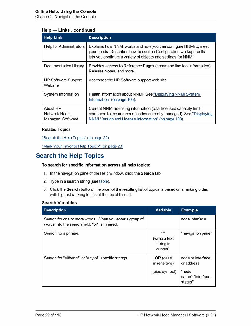
Help Link Description
Using the <name>form
Context-sensitive help for the current form.
Using the Console Explains how to use the NNMi console, including how to navigatewithin the console, as well as how to access and use the forms andviews NNMi provides.
Help for Operators Describes how to use the views, forms, and additional NNMi featuresthat are useful for monitoring and troubleshooting the network.
Help→ Links
HP Network NodeManager i Software (9.21)Page 21 of 113
Online Help: Using the ConsoleChapter 2: Navigating the Console
Help Link Description
Help for Administrators Explains how NNMi works and how you can configure NNMi tomeetyour needs. Describes how to use the Configuration workspace thatlets you configure a variety of objects and settings for NNMi.
Documentation Library Provides access to Reference Pages (command line tool information),Release Notes, andmore.
HP Software SupportWebsite
Accesses the HP Software support web site.
System Information Health information about NNMi. See "Displaying NNMi SystemInformation" (on page 105).
About HPNetwork NodeManager i Software
Current NNMi licensing information (total licensed capacity limitcompared to the number of nodes currently managed). See "DisplayingNNMi Version and License Information" (on page 108).
Help → Links , continued
Related Topics
"Search the Help Topics" (on page 22)
"Mark Your Favorite Help Topics" (on page 23)
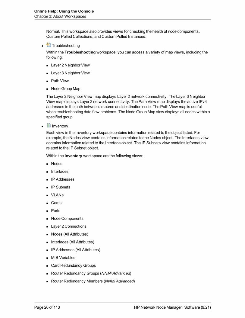
Search the Help TopicsTo search for specific information across all help topics:
1. In the navigation pane of the Help window, click theSearch tab.
2. Type in a search string (see table).
3. Click theSearch button. The order of the resulting list of topics is based on a ranking order,with highest ranking topics at the top of the list.
Description Variable Example
Search for one or more words. When you enter a group ofwords into the search field, "or" is inferred.
node interface
Search for a phrase. " "(wrap a textstring inquotes)
"navigation pane"
Search for "either of" or "any of" specific strings. OR (caseinsensitive)
| (pipe symbol)
node or interfaceor address
"nodename"|"interfacestatus"
Search Variables
HP Network NodeManager i Software (9.21)Page 22 of 113

Online Help: Using the ConsoleChapter 2: Navigating the Console
Description Variable Example
Search for two or more specific strings. AND (caseinsensitive)
+ (plus symbol)
& (ampersand)
node Andinterface Andaddress
"nodename"+address
"nodename"&"interface"
Search for all topics that do not contain something. NOT (caseinsensitive)
! (exclamationmark)
not node
! node
Search for all topics that contain one string and do notcontain another.
^ (caratsymbol)
node ^ interface
Combinations of the above. ( ) parenthesis node and (name orstatus)
node or vlan(!address)
Search Variables , continued
Note: Results returned are case insensitive. However, results ranking takes case into accountand assigns higher scores to casematches. Therefore, a search for "templates" followed by asearch for "Templates" would return the same number of help topics, but the order in which thetopics are listed would be different.
Mark Your Favorite Help TopicsUse the Favorites tab in the Help system to set favorites for your commonly used help topics.
When using this feature, note the following:
l This feature is not related to the Favorites option in yourWeb browser.
l Any time you delete yourWeb browser cookies, your help topic favorites list is deleted.
HP Network NodeManager i Software (9.21)Page 23 of 113

Chapter 3
About WorkspacesA workspace is a collection of views that represent a scope of interest and work. Workspacesgroup views with a related purpose or task flow.
When you click the name of a workspace, the views associated with that workspace display belowthe workspace in the workspace navigation panel. After you select a view, the view display panelshows the requested data. See "About the NNMi Console" (on page 9) and "Display Views" (onpage 15) for more information about the workspace navigation and view display panels.
The views within workspaces provide convenient access to information associated with eachobject type represented. A view displays all the objects of a given type that meet the filter criteriaspecified for that view.
Note: Someworkspaces appear under folders. To access the list of workspaces available fora folder, click the + (plus sign) that precedes the folder name.
NNMi includes the following workspaces:
l Incident Management
Use the Incident Managementworkspace to access the incidents that aremost importantto the network Operator and that often require more immediate action, (incidents with theLifecycle State equal to Registered, In Progress, or Completed). Key Incident1views include:
n Open Key Incident views that include those incidents with a Correlation Nature equal to anyof the following:
IncidentCorrelationNature Description
Info This Correlation Nature is meant to be informational.
None Indicates there is no incident correlation for this incident.
RateStreamCorrelation
Indicates the incident tracks incident patterns based on the number ofincident reoccurrences within a specified time period. After the count withinthe specified time period is reached, NNMi emits a Rate Correlation incidentand continues to update the Correlation Notes with the number ofoccurrences within that rate.
Root Indicates the incident that reports the root cause of a problem.
1Incidents with both: (1) Severity = other than Normal. (2) Correlation Nature = equal to RootCause, Service Impact, Stream Correlation, Rate Stream Correlation, Info, or None.
HP Network NodeManager i Software (9.21)Page 24 of 113

Online Help: Using the ConsoleChapter 3: About Workspaces
IncidentCorrelationNature Description
Cause
ServiceImpact
Used in NNMi 8.xx only. Indicates a relationship between incidents in whicha network service is effected by other incidents. By default, NNMi generatesService Impact incidents for Router Redundancy Groups. For example, anInterface Down incident can effect a Router Redundancy Group that is partof an HSRP service. The Service Impact incident helps to identify theservice that is affected.
This Correlation Nature is available for use by HP Network NodeManager iSoftware Smart Plug-ins (iSPIs). See "Help for Administrators" for moreinformation about NNM iSPIs.
StreamCorrelation
Used in NNMi 8.xx only. Indicates the correlations that NNMi's eventpipeline establishes as it recognizes patterns in the flow of events throughthe pipeline. Correlations are created as NNMi analyzes events and traps todetermine the root cause incident for a problem. Examples of streamcorrelations include Dedup (duplication of events) and Rate (occurrence ofevents by time) correlations.
n Unassigned Open Key Incident views include any unassigned Key Incidents.
n My Open incidents view includes all incidents that are assigned to the current user.
l Topology MapsThe Topology Mapsworkspace includes a NodeGroupmap view of all top-level NodeGroupscreated in your network, as well as map views of your Network Device Infrastructure, Layer 3(routers) and Layer 2 (switches) network. See "About Node and Interface Groups" (on page 49)for more information about NodeGroups. An NNMi administrator, or a role assigned by theNNMi administrator, can change themap views listed in this workspace. See "Help forAdministrators" for more information.
The Topology Mapsworkspace also includes the Initial Discovery Progress or NetworkOverview map, which displays amap containing themost highly connected nodes in the Layer 3network.
Note: The Initial Discovery Progressmap displays amaximum of 100 nodes. Thismaximum number cannot be changed. The Network Overview map displays amaximum of250 nodes by default. The NNMi administrator can change this maximum number using aconfiguration file. If you are an NNMi administrator, for more information, see the "NNMiConsole" chapter in theHP Network NodeManager i Software Deployment Reference,which is available at: http://h20230.www2.hp.com/selfsolve/manuals.
l MonitoringTheMonitoringworkspace includes views to check for those nodes, interfaces, IP addresses,Router Redundancy Groups, and NodeGroups that have a Status of Critical or other than
HP Network NodeManager i Software (9.21)Page 25 of 113
Online Help: Using the ConsoleChapter 3: About Workspaces
Normal. This workspace also provides views for checking the health of node components,Custom Polled Collections, and Custom Polled Instances.
l TroubleshootingWithin the Troubleshooting workspace, you can access a variety of map views, including thefollowing:
n Layer 2 Neighbor View
n Layer 3 Neighbor View
n Path View
n NodeGroupMap
The Layer 2 Neighbor View map displays Layer 2 network connectivity. The Layer 3 NeighborView map displays Layer 3 network connectivity. The Path View map displays the active IPv4addresses in the path between a source and destination node. The Path View map is usefulwhen troubleshooting data flow problems. The NodeGroupMap view displays all nodes within aspecified group.
l InventoryEach view in the Inventory workspace contains information related to the object listed. Forexample, the Nodes view contains information related to the Nodes object. The Interfaces viewcontains information related to the Interface object. The IP Subnets view contains informationrelated to the IP Subnet object.
Within the Inventory workspace are the following views:
n Nodes
n Interfaces
n IP Addresses
n IP Subnets
n VLANs
n Cards
n Ports
n NodeComponents
n Layer 2 Connections
n Nodes (All Attributes)
n Interfaces (All Attributes)
n IP Addresses (All Attributes)
n MIB Variables
n Card Redundancy Groups
n Router Redundancy Groups (NNMi Advanced)
n Router Redundancy Members (NNMi Advanced)
HP Network NodeManager i Software (9.21)Page 26 of 113

Online Help: Using the ConsoleChapter 3: About Workspaces
n NodeGroups
n Interface Groups
l Management ModeThis workspace includes views of discovered network elements that are not currently beingmanaged by NNMi:
n Unmanaged Nodes
n Unmanaged Interfaces
n Unmanaged IP Addresses
n Unmanaged Cards
n Unmanaged Node Components
l Incident BrowsingThe Incident Browsingworkspace includes the following views related to any Key Incident1:
n Open Key Incidents
n Closed Key Incidents
Each of these Key Incident views is filtered based on where the incident resides in its LifecycleState. For example, the Open Key Incidents view displays all Key Incidents that has a LifecycleState value other than Closed. The Closed Key Incidents view displays all incidents thathave a Lifecycle State of Closed.
The Incident Browsingworkspace also includes views for incidents based on their CorrelationNature. Examples includeOpen Root Cause and Service Impact incidents.
You can also use the Incident Browsingworkspace to view all incidents.
NNMi provides the Custom Incident and Custom Open Incident views that include all of theattributes available for an incident . These views are provided so that you can customize theincident views to include only the incident attributes of interest.
This workspace also includes views of incidents generated from NNM 6.x/7.x Events andSNMP Traps.
Note: If your role includes Administrator privileges, you also can access theManagementMode and Configuration workspaces. See "Help for Administrators" for more information.
Related Topics
"Views Provided by NNMi" (on page 85)
1Incidents with both: (1) Severity = other than Normal. (2) Correlation Nature = equal to RootCause, Service Impact, Stream Correlation, Rate Stream Correlation, Info, or None.
HP Network NodeManager i Software (9.21)Page 27 of 113

Chapter 4
About the Analysis PaneThe Analysis Pane displays related details about the selected object. NNMi performs theappropriate analysis on the selected object to determine themost important information to display.Any hyperlink within the Analysis Pane displays more information about the selected detail.For example: When you select an Incident, the Analysis Panemight include important details aboutthe incident's Source Node and Source Object. When you select a Node, the Analysis Panemightinclude important information about the node's Interfaces and IP Addresses.
To access the Analysis Pane from a table view:
1. Select the workspace of interest (for example, Inventory).
2. Select the view that contains the object of interest (for example, theNodes view).
3. Select the row that contains the object of interest.
4. NNMi displays detailed information at the bottom of the view in the Analysis Pane.
To access the Analysis Pane in a map view:
1. Select the workspace of interest (for example, Topology Maps).
2. Select amap view (for example, select Routers).
Note: If themap requires a starting node before it opens, enter the name orIP Address for the starting node you want to use.
3. Click themap object of interest.
4. NNMi displays detailed information at the bottom of the view in the Analysis Pane.
To access the Analysis Pane in a form:
l Click the form's toolbar Show Analysis icon to display information about the current form'stop-level object in the Analysis Pane.
Note: Show Analysis always displays the top-level object's information.
l Click a row in a table on one of the form's tabs to display detailed information about the selectedobject in the Analysis Pane.
NNMi displays detailed information at the bottom of the form in the Analysis Pane. SeeWorkingwith Objects for more information about forms.
Note the following:
l Look for one of the following at the bottom of the display area:
HP Network NodeManager i Software (9.21)Page 28 of 113

Online Help: Using the ConsoleChapter 4: About the Analysis Pane
Open the Analysis Pane if necessary by clicking the expand button.
l Place your mouse cursor over the title bar to display the ↕ symbol, then resize as necessary.
l The Analysis Pane remains blank until an object is selected.
l If you select multiple objects or clear a selection, NNMi retains the Analysis Pane's contents.
l If you change views, NNMi clears the Analysis Pane.
l Click any Refresh icon in the Analysis Pane to update a subset of displayed information.
l NNMi automatically refreshes the entire Analysis Pane's contents when you save a form.
l TheGauges tab shows real-time SNMP gauges to display State Poller and Custom PollerSNMP data.
n These gauges are displayed for Nodes, Interfaces, Custom Node Collections, and for NodeComponents of type CPU, Memory, Buffers, or Backplane.
n NNMi displays a gauge for each significant MIB Object Identifier (OID) that the node orinterface supports, up to the default maximum of 24.
Tip: If you are an NNMi administrator, for information about using the nms-ui.properties file to change this default, see the "NNMi Console" chapter in theHPNetwork NodeManager i Software Deployment Reference, which is available at:http://h20230.www2.hp.com/selfsolve/manuals.
n Each gauge displays the current OID value, using the default refresh rate of 15 seconds. (Ifyou are an NNMi administrator, for information about using the nms-ui.properties file tochange this default, see the "NNMi Console" chapter of theHP Network NodeManager iSoftware Deployment Reference, which is available at:http://h20230.www2.hp.com/selfsolve/manuals.)
n The value range displayed indicates the OID minimum andmaximum values that NNMi hasencountered.
n For any gauge that tracks percentage values, NNMi uses a red line to indicate where the OIDvalue is near 100 percent.
n There is not a one-to-onematch between theOIDs used to analyzemonitoring thresholds andthose displayed in the Analysis Pane. For example, the Analysis Panemight display aCiscoMemory Pool OID value that does not match the value used to calculate whether theMemory UtilizationMonitored Attribute threshold is reached or exceeded. This is becausesome thresholdmetrics require more complex calculations than a single OID allows.
Tip: If a gauge label appears to be a duplicate value, mouse over the label to view themore complete tooltip name that appears. (If you are an NNMi administrator, to changethe gauge title from the NNMi component name to the SNMP MIB variable name, see the"Maintaining NNMi" chapter of theHP Network NodeManager i Software DeploymentReference, which is available at:http://h20230.www2.hp.com/selfsolve/manuals.)
n To launch an SNMP LineGraph for the selectedmetric, click the icon that appears at thebottom of each gauge.
HP Network NodeManager i Software (9.21)Page 29 of 113

Online Help: Using the ConsoleChapter 4: About the Analysis Pane
n To select and copy the tooltip information, double-click the gauge. NNMi opens a text windowthat enables you to select and copy the tooltip information.
Tip: Tip: Some views are also accessible from the console's Actionsmenu. See "UsingActions to Perform Tasks" (on page 100) for more information.
You can right-click any object in a table or map view to access theActionsmenu.
For more information about the types of information displayed, see Use the Analysis Pane.
Related Topics
"Use Table Views" (on page 42)
"UseMap Views" (on page 63)
HP Network NodeManager i Software (9.21)Page 30 of 113

Chapter 5
Using the View ToolbarsNNMi provides toolbars for the following types of views:
l Table views toolbar
l NodeGroupMap views toolbar
l Neighbor views toolbar
l Path View toolbar
l Network Overview toolbar
Table View Toolbar
This is the table view display panel toolbar:
Use the table view toolbar to perform the following tasks within the displayed view.
Icon Description
Show View in New Window. Displays the current view in anew window.
New. NNMi Administrators only. Opens the form to create anew object instance.
Open. Displays the form for the selected object. See "AccessMore Information About anObject (Forms and Analysis Pane)" (on page 16).
Refresh. Refreshes the current view. See "Refresh a View"(on page 41) for more information. Restarts periodic refresh ifit has been disabled.
Stop Periodic Refresh. Temporarily disables the periodicrefresh of a view. See "Stop Periodic Refresh of a View" (onpage 45) for more information.
Restore Default Settings. Resets default settings, includingthe resizing of table columns, sort selections, and filters. Anyhidden columns are restored to the view. See "Hide a Column"
View Toolbar Icons
HP Network NodeManager i Software (9.21)Page 31 of 113

Online Help: Using the ConsoleChapter 5: Using the View Toolbars
Icon Description
(on page 43).
Restore Default Filters. Clears any currently applied filters.See "Filter a Table View" (on page 45).
Delete. If your role permits, deletes the selected objectinstance and any objects contained in that object. Forexample, deleting a node also deletes the interface andaddress instances associated with that node, and the historyof those objects.
Close. Close the current view.
Selects a time period filter. This filter only appears in incidentviews.
Selects an available node group or interface group filter.
The page controls only appears when viewing tables. They let you page through table informationby rows.
Use Previous or [Page Up] to move up one page.
Use Next or [Page Down] to move down one page.
Use First or [Home] to move to the top of the table.
Use Last or [End] to move to the end of the table.
Use the [ ↑ ]up arrow key to scroll up one row.
Use the [ ↓ ] down arrow key to scroll down one row.
The page control displays the total number of rows in the current table, as well as which group ofrows within that total is currently visible.
If the page control displays <maximum_table_size value>, this means the table row countexceeds themaximum table size specified by NNMi.
To view the actual table size, look for the Total value in the table status bar. NNMi displays thetotal number of rows for the table, followed by the display limit set for the table.
When the table size exceeds themaximum table size value, also note the following:
l NNMi recomputes the actual number of rows in the table each time you refresh the table viewor update the table filter.
l When you scroll to the last row of the table, NNMi displays a dialog explaining that the table islarger than the specified limit and recommending that you filter the table view. See "Filter aTable View" (on page 45) for more information about how to filter a table view.
View Toolbar Icons, continued
HP Network NodeManager i Software (9.21)Page 32 of 113

Online Help: Using the ConsoleChapter 5: Using the View Toolbars
Icon Description
or Toggles text-wrap on or off.
View Toolbar Icons, continued
Node Group Map Toolbar
This is the NodeGroupMap display panel toolbar:
The NodeGroupMap view toolbar lets you perform the following tasks within the displayedmap.
Icon Description
Show View in New Window. (Only available from themain console.)Displays the current view in a new window.
Open. Displays the form for the selected object. See "Access MoreInformation About anObject (Forms and Analysis Pane)" (on page 16).
Open Node Group Map. Opens the NodeGroupMap for the selectedChildNodeGroup. TheChildNodeGroupmap replaces the current mapand displays each node within theChildNodeGroup.
Note: You can also double-click the NodeGroup symbol toopen theChildNodeGroupMap.
See "About Node and Interface Groups" (on page 49) for more informationabout NodeGroups.
Save Layout. Saves the current position of each of the nodes on thecurrent NodeGroupMap.
Note: Each time you use this option, any previous location information isdeleted.
Refresh. Refreshes the current view. See "Refresh a View" (on page 41)for more information.
Refresh Status. Refreshes only the status of each node in themap. See"Refresh Node Status on aMap" (on page 67) for more information.
Fit Content. Adjusts the size of the node symbols so that all members ofthe NodeGroup fit within the current window. See "Adjust the ZoomFactor" (on page 65) for more information.
Node Group Map Toolbar Icons
HP Network NodeManager i Software (9.21)Page 33 of 113

Online Help: Using the ConsoleChapter 5: Using the View Toolbars
Icon Description
Actual Size. Cancels any current zoom setting. See "Adjust the ZoomFactor" (on page 65) for more information.
Zoom Out. Zooms out 25% of current size. See "Adjust the ZoomFactor" (on page 65) for more information.
Zoom In. Zooms in 25% of current size. See "Adjust the Zoom Factor"(on page 65) for more information.
Close. Close the current view.
Enables you to identify the NodeGroup for themap you want to display.
Note: As you type, NNMi provides a selection list of all current validentries matching your criteria (case sensitive). Youmust use one ofthe suggested values.
or Find. Toggles on or off highlighting the identified Node in the current mapand ensures that node is in themap's display area. See "Find a Node in aMap" (on page 66).
or Indicate Key Incidents. Toggles on or off NNMi's enlarging any mapsymbol that has an associatedKey Incident1. See "NodeGroupMapObjects" (on page 77) for more information.
or Tool Tips. Toggles on or off Tool Tips information that pops up when themouse cursor is placed over an object on amap. See "Control Tool TipsInformation on aMap" (on page 67) for more information.
Node Group Map Toolbar Icons , continued
Neighbor View Toolbar
This is the neighbor view display panel toolbar:
The neighbor view toolbar lets you perform the following tasks within the displayed view.
Icon Description
Show View in New Window. (Only available from themain console.) Show View in New Window. Displays the current view in a new window.
Neighbor View Toolbar Icons
1Incidents with both: (1) Severity = other than Normal. (2) Correlation Nature = equal to RootCause, Service Impact, Stream Correlation, Rate Stream Correlation, Info, or None.
HP Network NodeManager i Software (9.21)Page 34 of 113

Online Help: Using the ConsoleChapter 5: Using the View Toolbars
Icon Description
Open. Displays the form for the selected object. See "Access MoreInformation About anObject (Forms and Analysis Pane)" (on page 16).
Refresh. Refreshes the current view. See "Refresh a View" (on page 41)for more information.
Refresh Status. Refreshes only the status of each node in themap. See"Refresh Node Status on aMap" (on page 67) for more information.
Fit Content. Adjusts the size of the node symbols so that all members ofthe NodeGroup fit within the current window. See "Adjust the ZoomFactor" (on page 65) for more information.
Actual Size. Cancels any current zoom setting. See "Adjust the ZoomFactor" (on page 65) for more information.
Zoom Out. Zooms out 25% of current size. See "Adjust the ZoomFactor" (on page 65) for more information.
Zoom In. Zooms in 25% of current size. See "Adjust the Zoom Factor"(on page 65) for more information.
Close. Close the current view.
Specify the starting node for the neighbors you want to map. Populatethis field with the current value of the node's Name attribute or one of theNode's IP addresses.
Note: As you type, NNMi provides a selection list of all current validentries matching your criteria. Youmust use one of the suggestedvalues.
Select the number of hops to be displayed within themap view. A hop is anode representing any network device, such as a workstation, gateway,or switch, which is connected by a link with no intermediate nodes.
or Find. Toggles on or off highlighting the identified Node in the current mapand ensures that node is in themap's display area. See "Find a Node in aMap" (on page 66).
or Tool Tips. Toggles on or off Tool Tips information that pops up when themouse cursor is placed over an object on amap. See "Control Tool TipsInformation on aMap" (on page 67) for more information.
Neighbor View Toolbar Icons, continued
Path View Toolbar
This is the Path View display panel toolbar:
HP Network NodeManager i Software (9.21)Page 35 of 113

Online Help: Using the ConsoleChapter 5: Using the View Toolbars
The Path View toolbar lets you perform the following tasks within the displayed view.
Icon Description
Show View in New Window. (Only available from themain console.) Displays the current view in a new window.
Open. Displays the form for the selected object. See "Access MoreInformation About anObject (Forms and Analysis Pane)" (on page 16).
Refresh. Refreshes the current view. See "Refresh a View" (on page 41)for more information.
Refresh Status. Refreshes only the status of each node in themap. See"Refresh Node Status on aMap" (on page 67) for more information.
Fit Content. Adjusts the size of the node symbols so that all members ofthe NodeGroup fit within the current window. See "Adjust the ZoomFactor" (on page 65) for more information.
Actual Size. Cancels any current zoom setting. See "Adjust the ZoomFactor" (on page 65) for more information.
Zoom Out. Zooms out 25% of current size. See "Adjust the ZoomFactor" (on page 65) for more information.
Zoom In. Zooms in 25% of current size. See "Adjust the Zoom Factor"(on page 65) for more information.
Close. Close the current view.
Specify the source node to be used in the Path View.
Caution: Do not specify a node that is a switch.
Populate this field with the current value of the node's Hostname attribute(case-sensitive) or one of the node's IPv4 addresses. These are thevalues from the Node form.
Note: As you type, the auto-complete feature displays a list ofpossible matches. Select any item from the list.
NNMi Advanced. Path View works only with IPv4 addresses. The NNMiAdvanced IPv6 address values are not valid choices for Path View. Anydevices in your network that are configured with IPv6 addresses cannot
Path View Toolbar Icons
HP Network NodeManager i Software (9.21)Page 36 of 113

Online Help: Using the ConsoleChapter 5: Using the View Toolbars
Icon Description
be displayed on Path View maps.
Swap Nodes. Swaps the source and destination nodes in the Path View.
Specify the destination node in the Path View.
Caution: Do not specify a node that is a switch.
Populate this field with the current value of the node's Hostname attribute(case-sensitive) or one of the node's IPv4 addresses. These are thevalues from the Node form.
Note: As you type, the auto-complete feature displays a list ofpossible matches. Select any item from the list.
NNMi Advanced. Path View works only with IPv4 addresses. The NNMiAdvanced IPv6 address values are not valid choices for Path View. Anydevices in your network that are configured with IPv6 addresses cannotbe displayed on Path View maps.
Compute Path. Computes the Path View.
Note: Also use this icon to re-compute the Path View.
or Find. Toggles on or off highlighting the identified Node in the current mapand ensures that node is in themap's display area. See "Find a Node in aMap" (on page 66).
or Tool Tips. Toggles on or off Tool Tips information that pops up when themouse cursor is placed over an object on amap. See "Control Tool TipsInformation on aMap" (on page 67) for more information.
Path View Toolbar Icons, continued
Network Overview Toolbar
This is the Network Overview display panel toolbar:
The Network Overview toolbar lets you perform the following tasks within the displayed view.
Icon Description
Show View in New Window. (Only available from themain console.) Displays thecurrent view in a new window.
Network Overview Toolbar Icons
HP Network NodeManager i Software (9.21)Page 37 of 113

Online Help: Using the ConsoleChapter 5: Using the View Toolbars
Icon Description
Open. Displays the form for the selected object. See "Access More Information About anObject (Forms and Analysis Pane)" (on page 16).
Refresh. Refreshes the current view. See "Refresh a View" (on page 41) for moreinformation.
Refresh Status. Refreshes only the status of each node in themap. See "Refresh NodeStatus on aMap" (on page 67) for more information.
Fit Content. Adjusts the size of the node symbols so that all members of the NodeGroupfit within the current window. See "Adjust the Zoom Factor" (on page 65) for moreinformation.
Actual Size. Cancels any current zoom setting. See "Adjust the Zoom Factor" (on page65) for more information.
Zoom Out. Zooms out 25% of current size. See "Adjust the Zoom Factor" (on page 65)for more information.
Zoom In. Zooms in 25% of current size. See "Adjust the Zoom Factor" (on page 65) formore information.
Close. Close the current view.
or
Find. Toggles on or off highlighting the identified Node in the current map and ensuresthat node is in themap's display area. See "Find a Node in aMap" (on page 66).
or
Tool Tips. Toggles on or off Tool Tips information that pops up when themouse cursor isplaced over an object on amap. See "Control Tool Tips Information on aMap" (on page67) for more information.
Network Overview Toolbar Icons, continued
HP Network NodeManager i Software (9.21)Page 38 of 113

Chapter 6
Using the Form ToolbarThis is the form toolbar:
If your role permits, the toolbar lets you perform the following tasks within the form. The group ofavailable actions can change from form to form:
Tip: You can right-click any object in a table or map view to access theActionsmenu.
Icon Action
Show Form in New Window. Displays the current form in a new window.
Note: NNMi closes the current form before displaying the form in a new window.
Show Analysis. Displays the Analysis Pane information for the current form. See "Aboutthe Analysis Pane" (on page 28) for more information.
Save. Saves the current form.
Save and New. Saves the current form, and opens a new empty form where you cancreate a new object instance.
Save and Close. Saves and closes the current form.
Refresh. Refreshes the data in the current form.
Delete. Deletes the selected object instance and any objects contained in that object. Forexample, deleting a node also deletes the interface and address instances associated withthat node, and the history of those objects.
Note:When you delete an object instance that is created using a filter, such as aNodeGroup or Interface Group, NNMi deletes only the Node or Interface Group filter.NNMi does not remove the nodes or interfaces that belong to the selected group.
Close. Closes the current form.
Form Toolbar Icon Actions
Related Topics
"Access More Information About anObject (Forms and Analysis Pane)" (on page 16)
HP Network NodeManager i Software (9.21)Page 39 of 113

Chapter 7
Using Views to Display DataA view is the primary mechanism for displaying data. In the console, many views are available tohelp you visualize your network.
View Type Strength
Table Views Present summary information for a list of objects in a sorted order. Examplesinclude: viewing a list of incidents sorted by Status and filtered by Lifecycle State.
Map Views Display graphical relationships among objects.
Type of Views in the NNMi Console
To access a view, select a workspace and then click the view that you want to display. Someviews are also accessible from the console's Actionsmenu. See "Using Actions to PerformTasks" (on page 100) for more information.
You can right-click any object in a table or map view to access theActionsmenu.
Note: SomeNNMi users can delete nodes and other objects from the NNMi database(depending on the assigned NNMi Role). Any node that has been deleted appears as atransparent icon to all NNMi users until their map is refreshed using the Refresh icon. AfterRefresh, the deleted node is removed from themap. NNMi does not automatically refresh theconnectivity or set of nodes in amap view, except on the Initial Discovery Progress andNetwork Overviewmaps.
From a view, you can:
l "Select Multiple Objects" (on page 41)
l "Refresh a View" (on page 41) ( )
l "Refresh Node Status on aMap" (on page 67) ( )
l "Stop Periodic Refresh of a View" (on page 45) ( )
l "Using the View Toolbars" (on page 31) to Display a View in a New Window ( )
l "Invoke Actions" (on page 19)
Depending on the NNMi Role to which you are assigned, youmay or may not be allowed to createor delete instances of some objects from the view. SeeHelp→Help for Administrators for moreinformation.
Related Topics
"Use Table Views" (on page 42)
"UseMap Views" (on page 63)
HP Network NodeManager i Software (9.21)Page 40 of 113

Online Help: Using the ConsoleChapter 7: Using Views to Display Data
Select Multiple ObjectsYou can select or deselect multiple objects when using a table or map view. This feature is usefulwhen you want to access details or invoke an action onmultiple objects, such as nodes, IPaddresses, or interfaces.
Multiple Objects in Table Views
Tip: Look in the status bar of each table view to see the number of objects currently selectedas well as the total number of objects in the view.
To select multiple objects in a table view:Press CTRL-Click and select the row for each object you want to select.
To de-select an object in a table view:Re-select the row for each object you want to de-select.
Multiple Objects in Map Views
To select multiple objects in a map view:UseCTRL-Click to select each object of interest on themap.
Each object you select changes to indicate it has been selected.
To de-select an object in a map view:Re-select an object of interest on themap.
Each object you de-select returns to normal on themap.
Related Topics
"Select all Rows in a Table" (on page 43)
Refresh a ViewYou canmanually refresh a view at any time so that you are viewing the latest set of information.You cannot change the automatic refresh rate that was set by NNMi for each view.
To refresh a table view:
Click the Refresh icon in the table view toolbar to manually refresh your view.
The table view status bar displays the refresh rate and whether the refresh rate is enabled ordisabled. (If disabled, clicking the Refresh icon enables periodic refresh.)
To refresh a map view:
Click the Refresh icon in themap view toolbar to update changes in node placement, nodesadded, and nodes deleted.
To refresh the status of nodes on amap, see "Refresh Node Status on aMap" (on page 67).
Related Topics
"Stop Periodic Refresh of a View" (on page 45)
HP Network NodeManager i Software (9.21)Page 41 of 113

Online Help: Using the ConsoleChapter 7: Using Views to Display Data
Use Table ViewsTable views display data in tabular format. Each row displays data about one object. If there aremore rows than fits on a single screen, you can scroll through the table view using the scroll bar.
If a table contains more rows than themaximum limit set for a table, filter your table view to reducethe number of rows. See "Using the View Toolbars" (on page 31) for more information about howNNMi indicates the table has exceeded themaximum limit specified. See "Filter a Table View" (onpage 45) for information about how to filter a table view.
From a table view, in addition to the tasks accessed with the view display panel toolbar, you canperform the following tasks:
l "Resize a Column" (on page 42)
l "Hide a Column" (on page 43)
l "Sort ColumnData " (on page 44)
l "Filter a Table View" (on page 45)
l "Restore Table Defaults" (on page 61)
l "Export Table Information" (on page 61)
l "Invoke Actions" (on page 19)
l "Access More Information About anObject (Forms and Analysis Pane)" (on page 16)
The following customizations are saved across browser sessions:
l Columnwidth
l Hidden columns
l Sort column and order
l Column filters
l Quick filter value
l Node or interface group filter
l Time period filter (for incidents)
See "Limits to View Settings" (on page 63) for more information about the number of tables thathave customizations that can be stored.
Resize a ColumnYou can resize columns using your mouse.
To resize a column in the table:
1. Mouse over the edge of the column until you see a↔ resize icon.
2. Drag the column edge to the width you want.
Related Topics
"Hide a Column" (on page 43)
"Sort ColumnData " (on page 44)
HP Network NodeManager i Software (9.21)Page 42 of 113

Online Help: Using the ConsoleChapter 7: Using Views to Display Data
Hide a ColumnIf you find you no longer want to include a column of information in your view, you can hide aspecified column.
To hide a table column:
1. Right-click the column of interest.
2. Select Visibility.
The list of column names appears.
3. Click to clear the check box that precedes the name of the column you want to hide.
Related Topics
"Display a Hidden Column" (on page 43)
"Resize a Column" (on page 42)
"Sort ColumnData " (on page 44)
Display a Hidden ColumnIf you want to display a hidden column.
To display a hidden table column:
1. Right-click the column of interest.
2. Select Visibility.
The list of column names appears.
3. Click to check the check box that precedes the name of the column you want to display.
Related Topics
"Hide a Column" (on page 43)
"Resize a Column" (on page 42)
"Sort ColumnData " (on page 44)
Select all Rows in a TableIf you want to select all rows in a table.
To select all rows in a table:
1. Right-click in the table view.
2. Select Select All.
Tip: You can also use CTRL-A to select all rows in a table.
The table view data appears highlighted.
Related Topics
"Filter a Table View" (on page 45)
HP Network NodeManager i Software (9.21)Page 43 of 113

Online Help: Using the ConsoleChapter 7: Using Views to Display Data
"Hide a Column" (on page 43)
"Resize a Column" (on page 42)
"Restore Table Defaults" (on page 61)
Sort Column Data By sorting columns, you can get themost important information at the top of your table. Forexample, at times youmight want to view all critical nodes. At other times, youmight need to findnode contact information.
To sort by columns:
1. Right-click the column heading or data cell on which you want to sort.
2. To sort the column in ascending order, select Sort:→ Ascending
3. To sort the column in descending order, select Sort:→ Descending
When sorting column data, note the following:
l You can click the column header to initiate a sort on the column values. Clicking the columnheading again, reverses the sort direction.
l HP Network NodeManager i Software Smart Plug-ins (iSPIs) might provide table views inwhich sorting is disabled for one or more columns.
l Sorting tables that contain large amounts of data (for example, viewing all interfaces orincidents), can sometimes result in slow response times. In this case, it is better to first filter thetable information so that it contains only the values of interest before performing your sort.
More About Sorting
When sorting table columns, note the following:
l You can sort on only one column heading at one time.
l Capital letters are sorted separately from lowercase.
l NNMi sorts some table columns using lexicographical ordering. This might produce unfamiliarorders for strings such as Object IDs that contain numbers. For example youmight expect thefollowing order when sorting the sysObjectID data type:n 1.3.6.1.4.1.1
n 1.3.6.1.4.1.3
n 1.3.6.1.4.1.20
Using lexicographical ordering, these system object ID values are ordered as follows:
n 1.3.6.1.4.1.1
n 1.3.6.1.4.1.20
n 1.3.6.1.4.1.3
l Some table columns, such as Status and ifType, display data types which have a natural sortorder that is distinct from an alphabetical order. When sorting these columns, the values aresorted according to a natural or pre-determined order rather than alphabetically. For examplewhen sorting the Status column, you always see the following order (ascending) or the reverse
HP Network NodeManager i Software (9.21)Page 44 of 113

Online Help: Using the ConsoleChapter 7: Using Views to Display Data
(descending): Critical,Major,Minor,Warning, Unknown, Disabled, Normal, andNoStatus.
l Your sort choices are saved across user sessions.
Related Topics
"Filter a Table View" (on page 45)
"Hide a Column" (on page 43)
"Resize a Column" (on page 42)
"Restore Table Defaults" (on page 61)
"Select all Rows in a Table" (on page 43)
Stop Periodic Refresh of a ViewYou canmanually stop the periodic refresh of the group of items displayed in a table view at anytime.
Note: The status of this group of objects is always updated on a regular basis, you are onlystopping updates based on network objects being added or deleted from the NNMi database.
NNMi's status bar displays the refresh rate and whether the refresh rate has been disabled.
To stop the periodic refresh of a table view:
1. Click the Stop Periodic Refresh icon. In the bottom right corner of the NNMi console, thefollowingmessage displays:
2. If you want to restart the refresh rate, click the Refresh icon in the view display paneltoolbar. In the bottom right corner of the NNMi console, the followingmessage displays:
Note: You cannot change the refresh rate. NNMi sets that default rate for each view.
Related Topics
"Refresh a View" (on page 41)
Filter a Table ViewWhen using table views, you can reduce the amount of information displayed by filtering a viewusing one of the object's attribute values. For example, you can access only those incidents thathave a Status of Critical, or only those incidents that have a Description that is Interface Down.
HP Network NodeManager i Software (9.21)Page 45 of 113

Online Help: Using the ConsoleChapter 7: Using Views to Display Data
Filtering a table view is also useful to reduce the number of rows when a table contains more rowsthan themaximum limit set for a table. See "Using the View Toolbars" (on page 31) for moreinformation about how NNMi indicates the table has exceeded themaximum limit specified.
When a view is first displayed, it displays a set of filtered columns based on the view definitionprovided by NNMi.
Note: The view status bar indicates if one or more filters have been set for the view.FILTER:ON indicates that one or more filters have been set. These are filters that you canmodify. In some views, NNMi provides factory set filters that cannot be changed. For example,theMy Open Incidents view is filtered on the Assigned To attribute, which cannot be changed.FILTER:OFF indicates nomodifiable filters have been set for the view. These views mighthave factory set filters.
When specifying filters, you can perform the following tasks:
Drop-Down List Selection Filters
l "Filter Tables by Node or Interface Group" (on page 48)
l "Filter by Time Period (Incident Views Only)" (on page 50)
Column Selection Filters
l "Filter by Attribute Value" (on page 50)
l "Modify a Table View Filter" (on page 55)
l "Remove a Filter" (on page 59)
l "Restore Default Filters" (on page 59)
l "Display Current Filter Settings" (on page 60)
When using filters, note the following:
l You can filter onmultiple table columns. The resulting filter is a logical AND of the filters for all ofthe columns.
l HP Network NodeManager i Software Smart Plug-ins (iSPIs) might provide table views inwhich filtering is disabled for one or more columns.
l NNMi matches to themilliseconds when filtering on columns that represent time values (forexample, Last Occurrence). Therefore, only those times that match to themilliseconds areincluded in your view. Try using the less than or equal or greater than or equal filter options toinclude a wider range of time values.
l NNMi restricts certain filter operations or options per data type. Only the filter options that applyto the attribute data type appear. The data types and valid filter options are described in the tablebelow.
l A different subset of these filter options appears depending on whether you are clicking a datacell, a column header, or a blank row. A data cell filter menu includes filters that use the value ofthe selected data cell.
HP Network NodeManager i Software (9.21)Page 46 of 113

Online Help: Using the ConsoleChapter 7: Using Views to Display Data
Data Type Valid Filter Options
All data types Equals this value
Not equal to this value
See "Filter by Attribute Value" (on page 50) for moreinformation.
Text (String)
Numeric
Enumerated List
IP Address
Date and Time
Create Filter...
Boolean data types Is true
Is false
Numeric (Integer, IP address, anddate)
Greater than or equal to this value
Less than or equal to this value
See "Filter by Attribute Value" (on page 50) for moreinformation.
Filter Options Available
DataType Valid Filter Options
GroupFilter
Provides a drop-downmenu in the view display panel toolbar of the node and interfacegroups available to you.
See "Filter Tables by Node or Interface Group" (on page 48) for more information aboutgroup filters.
QuickFilter
Provides a drop-downmenu in the view display panel toolbar of all of the possible valuesfor an attribute. These drop-downmenus are provided for table views that include "by" inthe view name.
TimePeriodFilter
Provides a drop-downmenu in the view display panel toolbar in incident views. This filterlists a variety of time periods for which you can filter your incident views. Possiblevalues include: Last 5 minutes, Last Hour, Last 8 Hours, Last Day, Last 3 Days,Last Week, Last Month, andAll.
See "Filter by Time Period (Incident Views Only)" (on page 50) for more information.
Addtional Filter Options Available
HP Network NodeManager i Software (9.21)Page 47 of 113

Online Help: Using the ConsoleChapter 7: Using Views to Display Data
Filter Tables by Node or Interface Group
NNMi lets you filter your table views by node or interface group. For example, youmight want toview all of the important Cisco routers, or all of the Voice-Over-IP interfaces within your network.
Your NNMi administrator creates these groups. They are listed in a "group selector" drop-downmenu list on the view toolbar as shown below:
NodeGroup filters are available for:
l Node views
l Interface views
l IP address views
l Incident views
Note: NodeGroup filters are not available for the NNM 6.x/7.x Events view.
Interface Group filters are available for:
l Interface views
l IP Address views
l Card views
l NodeComponent views
To filter a view by Node or Interface Group:
1. Navigate to the view of interest.
a. From the workspace navigation panel, select the workspace that contains the view youwant to use; for example, Inventory.
b. Select the view of interest; for example, Interfaces.
2. In the group selector drop-down list, select the NodeGroupor Interface Group you want to use as a filter.
When using NodeGroup or Interface Group filters, note the following:
l By default, table views are not filtered by Node or Interface Group.
l If a view can be filtered by both NodeGroup and Interface Group, the selection box lists theNodeGroups first, followed by the Interface Groups. Each list appears in alphabetical order.
l When the filter is applied, the view automatically refreshes to show the appropriate set ofobjects.
l If you set a NodeGroup or Interface Group filter, NNMi combines the group filter with any otherfilters using the AND Boolean operator.
l To clear the group filter, return the selection value to "<Set node group filter>" or "<Set node orinterface group filter>".
Related Topics
HP Network NodeManager i Software (9.21)Page 48 of 113

Online Help: Using the ConsoleChapter 7: Using Views to Display Data
"Filter by Attribute Value" (on page 50)
"Modify a Table View Filter" (on page 55)
"Remove a Filter" (on page 59)
"Restore Default Filters" (on page 59)
"Display Current Filter Settings" (on page 60)
About Node and Interface Groups
Whenmonitoring your network, youmight be interested in only viewing information for a particularset of nodes or interfaces. Your network administrator can group sets of nodes or interfaces intonode or interface groups. An example NodeGroup could be all important Cisco routers, or all routersin a particular building. As another example, all interfaces used for Voice-Over-IP might be groupedtogether in your network.
Your administrator configures NodeGroups based on any of the following:
l Vendor or model SNMP object identifiers.
l Specific devices identified by name or IP address.
l Devices identified with wildcard characters to define a NodeGroup. These groups might bebased on a naming strategy that is set in place for your organization.
Note: NodeGroups can also control how NNMi monitors network devices. For example, youradministrator might configure each group to have a different health monitoring interval.
You can display the definition of a group:
l Node Group definitionsa. From the workspace navigation panel, select the Inventoryworkspace.
b. Select theNode Groups view.
c. Double-click the row representing the NodeGroup.
d. The NodeGroup form displays.
e. When finished, click the Close icon.
l Interface Group definitionsa. From the workspace navigation panel, select the Inventoryworkspace.
b. Select the Interface Groups view.
c. Double-click the row representing the Interface Group.
d. The Interface Group form displays.
Interface group definitions match the way your team identifies important network devices.Each interface group can include one or more interface-type specifications (based onindustry-standard IANA ifType-MIB variables).
e. When finished, click the Close icon.
HP Network NodeManager i Software (9.21)Page 49 of 113

Online Help: Using the ConsoleChapter 7: Using Views to Display Data
Special Actions are provided for NodeGroups and Interface Groups. See Using Actions to PerformTasks.
Filter by Time Period (Incident Views Only)
Incident views enable you to filter your view by time period. Filtering using the time period filter letsyou focus on themost recent incidents of interest. The available time periods include:
l Last 5Minutes
l Last Hour
l Last 8 Hours
l Last Day
l Last 3 Days
l Last Week
l Last Month
l All
Note: A month is defined as 31 days.
Filter by Attribute Value
When specifying filters based on attribute (column) values, some filter options require that youspecify the value by selecting the value in an object instance and some require that you open aCreate Filter... dialog to specify the value. You can also specify a filter based on whether anattribute contains a value.
l "Select Filter Values" (on page 50)
l "Create a Filter to Specify Values" (on page 51)
l "Use Null Value Filters" (on page 55)
Select Filter Values
The following filter options require an attribute value as the basis for the filter.
Note:When using the filter options listed below, first right-click the value in the table on whichyou want to filter.
Filter Option Description
Equals this value NNMi displays only instances that contain the attribute value you specify.
Not equal to thisvalue
NNMi displays only instances that have an attribute value that does NOTcontain the value specified.
You can specify multiple values for this filter; but can only supply one
Filter Settings
HP Network NodeManager i Software (9.21)Page 50 of 113

Online Help: Using the ConsoleChapter 7: Using Views to Display Data
Filter Option Description
value each time you select this option.
Note: For certain attributes, this option can also filter values that are"empty" or null.
Greater than orequal to this value
NNMi displays only instances that contain the attribute values that aregreater than or equal to the value you specify.
Less than or equal tothis value
NNMi displays only instances that contain the attribute values that areless than or equal to the value you specify.
Is true NNMi displays only instances that have an attribute value that containsthe value true.
Is false NNMi displays only instances that have an attribute value that containsthe value false.
Filter Settings , continued
You can change a filter at any time. NNMi saves filters per user so that the filters you specify aremaintained during subsequent user sessions. See "Limits to View Settings" (on page 63) forinformation about the number of tables that have customizations that can be saved based on yourweb browser. See "Restore Table Defaults" (on page 61) for information about how to remove tableview customizations.
To filter your view by selecting an attribute value in the table:
1. Right-click the attribute value on which you want to base your filter.
2. Select one of the following filter options:
n Equals this value
n Not equal to this value
n Greater than or equal to this value
n Less than or equal to this value
n Is true
n Is false
NNMi displays a table view of all instances that have been selected based on the filter optionand attribute values you specified or selected.
Each filtered column is indicated using the filter icon.
Related Topics
"Use Null Value Filters" (on page 55)
Create a Filter to Specify Values
NNMI enable you to provide attribute values on which you want to filter. You can provide attributesvalues by creating a filter for any of the following types of values:
HP Network NodeManager i Software (9.21)Page 51 of 113

Online Help: Using the ConsoleChapter 7: Using Views to Display Data
l Text (String)
l Numeric
l Enumerated List
l IP Address
l Date and Time
To filter information by specifying one or more values:
1. Right-click the column or attribute on which you want to filter.
2. Select Create filter...
NNMi displays the Filter Dialog that is appropriate for the selected column's data type.
3. In the Create Filter ... Dialog displayed:
a. Select a Filter Option (see Filter Option tables) .
b. Specify one or more valid values (see Valid Filter Values)
4. Click Apply.
NNMi displays a table view of all instances that have been selected based on the filter optionand attribute values you specified or selected.
Each filtered column is indicated using the filter icon.
FilterOption Description
startswith
NNMi displays only instances that have an attribute value that starts with the textstring value specified.
Use this option when you are looking for an entry that begins with a specific stringvalue. For example if all of your Cisco devices started with the text string "Cisco", andyou wanted to find all Cisco devices, you could use the value string "Cisco".
contains NNMi displays only those instances that have an attribute value that contains the textstring value you enter.
You can use the wildcard character ('*') to match one or more characters within thecontains value. For example, c*mmatches the following values:
3com9000
callmgr1
matches NNMi displays only those instances that have an attribute value that matches the textstring value you enter.
Use the questionmark (?) to match one character.
Use the asterisk (*) as a wildcard character to match zero or more characters.
Text (String) Filter Options
HP Network NodeManager i Software (9.21)Page 52 of 113
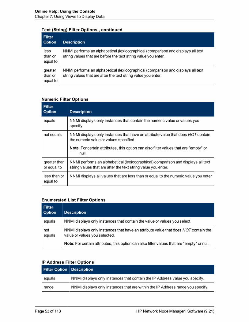
Online Help: Using the ConsoleChapter 7: Using Views to Display Data
FilterOption Description
lessthan orequal to
NNMi performs an alphabetical (lexicographical) comparison and displays all textstring values that are before the text string value you enter.
greaterthan orequal to
NNMi performs an alphabetical (lexicographical) comparison and displays all textstring values that are after the text string value you enter.
Text (String) Filter Options , continued
FilterOption Description
equals NNMi displays only instances that contain the numeric value or values youspecify.
not equals NNMi displays only instances that have an attribute value that does NOT containthe numeric value or values specified.
Note: For certain attributes, this option can also filter values that are "empty" ornull.
greater thanor equal to
NNMi performs an alphabetical (lexicographical) comparison and displays all textstring values that are after the text string value you enter.
less than orequal to
NNMi displays all values that are less than or equal to the numeric value you enter
Numeric Filter Options
FilterOption Description
equals NNMi displays only instances that contain the value or values you select.
notequals
NNMi displays only instances that have an attribute value that does NOT contain thevalue or values you selected.
Note: For certain attributes, this option can also filter values that are "empty" or null.
Enumerated List Filter Options
Filter Option Description
equals NNMi displays only instances that contain the IP Address value you specify.
range NNMi displays only instances that are within the IP Address range you specify.
IP Address Filter Options
HP Network NodeManager i Software (9.21)Page 53 of 113

Online Help: Using the ConsoleChapter 7: Using Views to Display Data
Filter Option Description
is empty NNMi displays only the instances that do not have a value for this attribute.
is not empty NNMi displays only the instances that contain a value for this attribute.
IP Address Filter Options, continued
FilterOption Description
on orafter
NNMi displays only instances that have date and time values that occur on or after thedate and time you specify.
on orbefore
NNMi displays only instances that have date and time values that occur on or beforethe date and time you specify.
between NNMi displays only instances that have date and time values that occur after the firstdate and time you specify and before the second date and time you specify.
Use the between operator when you want to filter on instances that occur within aspecified hour or day.
Date and Time Filter Options
Data Type Description
Text Enter the value for which you want NNMi to search. Text (string) filters are casesensitive.
Numeric Enter the numeric value or values for which you want NNMi to search. To entermore than one numeric value, enter a comma-separated list.
EnumeratedList
Select one or more values from the enumerated list.
IP Address Enter an IP Address (PIv4 or IPv6). You can specify ranges using two IPaddresses separated by a '-' or using Classless Inter-Domain Routing (CIDR)notation:
IPv4 examples:
10.168.0.1 - 10.168.13.1
10.2.120.0/21
IPv6 examples (i-Advanced only):
2001:d88:a00:: - 2001:d88:aff:ffff:ffff:ffff:ffff:ffff
2001:d88:0:a00::/56
Valid Filter Values
HP Network NodeManager i Software (9.21)Page 54 of 113
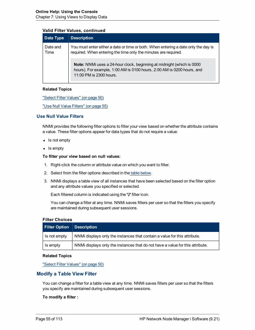
Online Help: Using the ConsoleChapter 7: Using Views to Display Data
Data Type Description
Date andTime
Youmust enter either a date or time or both. When entering a date only the day isrequired. When entering the time only theminutes are required.
Note: NNMi uses a 24-hour clock, beginning at midnight (which is 0000hours). For example, 1:00 AM is 0100 hours, 2:00 AM is 0200 hours, and11:00 PM is 2300 hours.
Valid Filter Values, continued
Related Topics
"Select Filter Values" (on page 50)
"Use Null Value Filters" (on page 55)
Use Null Value Filters
NNMi provides the following filter options to filter your view based on whether the attribute containsa value. These filter options appear for data types that do not require a value:
l Is not empty
l Is empty
To filter your view based on null values:
1. Right-click the column or attribute value on which you want to filter.
2. Select from the filter options described in the table below.
3. NNMi displays a table view of all instances that have been selected based on the filter optionand any attribute values you specified or selected.
Each filtered column is indicated using the filter icon.
You can change a filter at any time. NNMi saves filters per user so that the filters you specifyaremaintained during subsequent user sessions.
Filter Option Description
Is not empty NNMi displays only the instances that contain a value for this attribute.
Is empty NNMi displays only the instances that do not have a value for this attribute.
Filter Choices
Related Topics
"Select Filter Values" (on page 50)
Modify a Table View Filter
You can change a filter for a table view at any time. NNMi saves filters per user so that the filtersyou specify aremaintained during subsequent user sessions.
To modify a filter :
HP Network NodeManager i Software (9.21)Page 55 of 113

Online Help: Using the ConsoleChapter 7: Using Views to Display Data
1. Right-click the column or attribute on which you want to filter.
2. SelectModify filter...
Note the following:
n If a filter is not created for the selected table column, theModify filter... option does notappear.
n If you have used an existing attribute value with the Not equal to this value filter, you canselect an additional attribute value and select Not equal to this value also.
n NNMi displays the filter dialog that is appropriate for the selected column's data type. If thefilter was created using the “Not equal to this value” option with the Text (String) or IPaddress data type, NNMi does not include the values for the current filter.
3. In theModify Filter ... dialog displayed:
a. Select a Filter Option (see Filter Option tables) .
b. Specify one or more valid values (see Valid Filter Values)
4. Click Apply.
NNMi replaces the previous filter with the new filter values. NNMi displays a table view of allinstances that have been selected based on the filter option and attribute values you specifiedor selected.
Each filtered column is indicated using the filter icon.
FilterOption Description
startwith
NNMi displays only instances that have an attribute value that starts with the textstring value specified.
Use this option when you are looking for an entry that begins with a specific stringvalue. For example if all of your Cisco devices started with the text string "Cisco", andyou wanted to find all Cisco devices, you could use the value string "Cisco".
contains NNMi displays only those instances that have an attribute value that matches the textstring value you enter.
You can also use a wildcard character (*) within your string value.
If a wildcard is not specified, this filter option finds those values that exactly matchthe value string you enter. For example, if you wanted to find only the Cisco1 devicefrom the following list of values, you would use "Cisco1" as your value string:
l Cisco1
l Cisco12
l Cisco123
In this example, NNMi would not include Cisco12 and Cisco123.
Text (String) Filter Options
HP Network NodeManager i Software (9.21)Page 56 of 113

Online Help: Using the ConsoleChapter 7: Using Views to Display Data
FilterOption Description
matches NNMi displays only those instances that have an attribute value that matches the textstring value you enter.
Note: Do not use the asterisk (*) within your string value unless you want NNMitomatch * (asterisk).
lessthan orequal
NNMi performs an alphabetical (lexicographical) comparison and displays all textstring values that are before the text string value you enter.
greaterthan orequal
NNMi performs an alphabetical (lexicographical) comparison and displays all textstring values that are after the text string value you enter.
Text (String) Filter Options , continued
FilterOption Description
equal NNMi displays only instances that contain the numeric value or values you specify.
not equal NNMi displays only instances that have an attribute value that does NOT containthe numeric value or values specified.
greaterthan orequal
NNMi performs an alphabetical (lexicographical) comparison and displays all textstring values that are after the text string value you enter.
less thanor equal
NNMi displays all values that are less than or equal to the numeric value you enter.
Numeric Filter Options
FilterOption Description
equal NNMi displays only instances that contain the value or values you select.
not equal NNMi displays only instances that have an attribute value that does NOT contain thevalue or values you selected.
Enumerated List Filter Options
HP Network NodeManager i Software (9.21)Page 57 of 113

Online Help: Using the ConsoleChapter 7: Using Views to Display Data
Filter Option Description
equal NNMi displays only instances that contain the IP Address value you specify.
range NNMi displays only instances that are within the IP Address range you specify.
IP Address Filter Options
FilterOption Description
on orafter
NNMi displays only instances that have date and time values that occur on or after thedate and time you specify.
on orbefore
NNMi displays only instances that have date and time values that occur on or beforethe date and time you specify.
between NNMi displays only instances that have date and time values that occur after the firstdate and time you specify and before the second date and time you specify.
Use the between operator when you want to filter on instances that occur within aspecified hour or day.
Date and Time Filter Options
Data Type Description
Text Enter the value for which you want NNMi to search. Text (string) filters are casesensitive.
Numeric Enter the numeric value or values for which you want NNMi to search. To entermore than one numeric value, enter a comma-separated list.
EnumeratedList
Select one or more values from the enumerated list.
IP Address Enter an IP Address (IPv4 or IPv6). You can specify ranges using two IPaddresses separated by a '-' or using Classless Inter-Domain Routing (CIDR)notation:
IPv4 examples:
10.168.0.1 - 10.168.13.1
10.2.120.0/21
IPv6 examples (i-Advanced only):
2001:d88:a00:: - 2001:d88:aff:ffff:ffff:ffff:ffff:ffff
2001:d88:0:a00::/56
Valid Filter Values
HP Network NodeManager i Software (9.21)Page 58 of 113

Online Help: Using the ConsoleChapter 7: Using Views to Display Data
Data Type Description
Date andTime
Youmust enter either a date or time or both. When entering a date only the day isrequired. When entering the time only theminutes are required.
Note: NNMi uses a 24-hour clock, beginning at midnight (which is 0000 hours).For example, 1:00 AM is 0100 hours, 2:00 AM is 0200 hours, and 11:00 PMis 2300 hours.
Valid Filter Values , continued
Related Topics
"Filter Tables by Node or Interface Group" (on page 48)
"Filter by Attribute Value" (on page 50)
"Remove a Filter" (on page 59)
"Restore Default Filters" (on page 59)
"Display Current Filter Settings" (on page 60)
Remove a Filter
NNMi lets you remove a filter for a selected column at any time.
To remove a filter:
1. Right-click the column that has a filter that you want to remove.
2. Select Remove filter from the drop-downmenu.
NNMi removes all existing filters that have been set for that column.
Related Topics
"Modify a Table View Filter" (on page 55)
"Modify a Table View Filter" (on page 55)
"Restore Default Filters" (on page 59)
Restore Default Filters
You can restore the default filters for a view. This option removes any filters that you have definedfor the current view.
To restore the default filter settings:
In the table toolbar, click the Restore Default Filters icon.
Note: If you are viewing a table that appears in the form, open the table in a new window usingthe Show View In New Window icon, and then click the Restore Default Filters icon.
All filters are reset to the default values and any filters that you have created are removed for thecurrent view.
HP Network NodeManager i Software (9.21)Page 59 of 113

Online Help: Using the ConsoleChapter 7: Using Views to Display Data
Note: Youwill lose any selections you have in the view.
Related Topics
"Display Current Filter Settings" (on page 60)
"Remove a Filter" (on page 59)
Display Current Filter Settings
To keep track of the filters you have created, you can view the filter that has been set on a columnby column basis.
To view a column's filter:
Mouse over the column of interest.
The example below shows the filter option and the string provided for that filter:
The following table explains the symbols used for each filter option
Symbol Filter Option
<= Less than or equal to this value
>= Greater than or equal to this value
= Equals this value
NOT IN Not equal to this value
IS NULL Is empty
IS NOT NULL Is not empty
LIKE Contains string...
Starts with string...
Matches string...
Filter Definitions
Note: The percent sign (%) represents the wildcard character.
Related Topics
"Restore Default Filters" (on page 59)
"Modify a Table View Filter" (on page 55)
"Modify a Table View Filter" (on page 55)
"Remove a Filter" (on page 59)
HP Network NodeManager i Software (9.21)Page 60 of 113

Online Help: Using the ConsoleChapter 7: Using Views to Display Data
Restore Table DefaultsYou can remove the types of table view customizations described in the following table. Removecustomizations when you no longer find them useful or when you reach the limit for themaximumnumber of customizations that can be stored. See "Limits to View Settings" (on page 63) for moreinformation about the number of tables that have customizations that can be stored.
If you are concerned about reaching your table view settings limit, remove view settings for tablesthat are not important.
Note: The Restore Default Filters icon and Restore Default Settings icon do notappear on table views in forms. If you want to clear settings from a table view that appears in aform, use the Show in New Window icon to open the table view in a new window andperform these operations.
What You canRemove How Description
Only table viewfilters
From the view displaypanel toolbar, select
Restore DefaultFilters.
Clears all customizations to filters for the table viewand refreshes the view with the view's default filtersettings.
Allcustomizationsfor all tableviews
Select View→Restore All DefaultView Settings
Clears all customizations (and cookies) for all tableview customizations. See "Limits to View Settings"(on page 63) for more information about how NNMiuses cookies to store table view customizations.
Restore Default Table View Settings
Related Topics
"Filter a Table View" (on page 45)
"Hide a Column" (on page 43)
"Resize a Column" (on page 42)
"Restore Table Defaults" (on page 61)
"Select all Rows in a Table" (on page 43)
Export Table InformationYou can export the contents of a table view for use in other applications. You can choose to exportonly the rows that are selected or all of the rows in your table.
Note: Youmust have aminimum of Operator Level1 Role to export table information.
When printing table information, note the following:
l The first column of table information does not appear in the exported version. The contents ofthis column is for selection purposes only.
HP Network NodeManager i Software (9.21)Page 61 of 113

Online Help: Using the ConsoleChapter 7: Using Views to Display Data
l You can copy and paste the table data to other applications, such as Microsoft Excel, foradditional editing andmanipulating, such as getting a list of hostnames.
To export selected table rows:
1. Right-click any cell or column header within the table.
2. Select Export to CSV.
NNMi displays the Export to CSV dialog.
3. Select Selected Rows.
4. To included the table column headings in the exported data, click to check IncludeColumn Headings.
5. NNMi stores date and enumerated values in both localized (Jul 12, 2010 10:07 AM) and raw(1278950859739) format. By default, NNMi exports only the localized (human readable) formatfor date and enumerated values.
Select theRaw Data option to include only the raw (computer readable) format for both dateand enumerated values.
Select the Localized Data option to include only the localized (human readable) format for bothdates and enumerated values.
6. In the File Download dialog, select one of the following options.a. Open to view the file contents.
b. Save to save the file to a specified file name.
To export all table rows:
1. Right-click any cell or column header with the table.
2. Select Export to CSV
NNMi displays the Export to CSV dialog.
3. Select All Rows.
4. To included the table column headings in the exported data, click to check IncludeColumn Headings.
5. NNMi stores date and enumerated values in both localized (Jul 12, 2010 10:07 AM) and raw(1278950859739) format. By default, NNMi exports only the localized (human readable) formatfor date and enumerated values.
Select theRaw Data option to include only the raw (computer readable) format for both dateand enumerated values.
Select the Localized Data option to include only the localized (human readable) format for bothdates and enumerated values.
6. In the File Download dialog, select one of the following options.a. Open to view the file contents.
b. Save to save the file to a specified file name.
Related Topics
"Filter a Table View" (on page 45)
HP Network NodeManager i Software (9.21)Page 62 of 113

Online Help: Using the ConsoleChapter 7: Using Views to Display Data
"Hide a Column" (on page 43)
"Resize a Column" (on page 42)
"Restore Table Defaults" (on page 61)
"Select all Rows in a Table" (on page 43)
Limits to View SettingsNNMi automatically saves the following kinds of table view settings.:
l Columnwidth
l Hidden columns
l Sort column and order
l Filters
When customizing table views, note the following:
l All settings for each table are stored in a corresponding cookie for that table.
l The number of tables that have settings that can be saved, and the behavior when the limit isreached depends the browser you use:
Microsoft Internet Explorer discards your oldest cookie and lets you continue creatingcustomizations. If you are usingMicrosoft Internet Explorer, the cookie limit is 48.
If you are usingMozilla Firefox, the cookie limit is 48. If you reach the 48 limit, Mozilla Firefoxremoves the next to last cookie before saving the latest cookie created.
l Table view settings are specific to each operating system user. Therefore, if you log on as adifferent operating system user, you will have different view settings. If you sign into NNMi as adifferent NNMi user, but as the same operating system user, you will have the same viewsettings.
Note: NNMi displays a warningmessage when your last cookie and subsequent table settingsare being saved.
You can remove the customizations for all of your tables using theView→Restore All DefaultView Settings. See "Restore Table Defaults" (on page 61) for more information.
Related Topics
"Restore Default Filters" (on page 59)
"Hide a Column" (on page 43)
"Resize a Column" (on page 42)
"Select all Rows in a Table" (on page 43)
Use Map ViewsA map view is a powerful way to display information about your network. In amap view, nodes,interfaces, IP address, and subnets are represented as symbols on themap. The lines between thenodes and interfaces represent the connection or relationship between these objects.
HP Network NodeManager i Software (9.21)Page 63 of 113

Online Help: Using the ConsoleChapter 7: Using Views to Display Data
For each symbol, a background shape indicates the type of device, such as router or switch. See"About Map Symbols" (on page 73). The color of this background shape indicates the current healthof the device. See "About Status Colors" (on page 68) for more information about map color values
On themaps, a foreground image is placed over the background shape. The foreground imageidentifies themake andmodel of the network device.
You access map views from the Topology Maps and Troubleshooting workspaces. You can alsoopenmaps from table views using theActionsmenu. See "Access Maps Provided by NNMi" (onpage 82) and "Using Actions to Perform Tasks" (on page 100) for more information.
Tip: You can right-click any object in a table or map view to access theActionsmenu.
Depending on the type of map you are viewing, NNMi uses additional conventions to depict otherkinds of objects on themap:
"NodeGroupMapObjects" (on page 77)
"Layer 2 Neighbor View MapObjects" (on page 78)
"Layer 3 Neighbor View MapObjects" (on page 80)
"Path View Map Objects" (on page 81)
Note: SomeNNMi users can delete nodes and other objects from the NNMi database(depending on the assigned NNMi Role). Any node that has been deleted appears as atransparent icon to all NNMi users until their map is refreshed using the Refresh icon. AfterRefresh, the deleted node is removed from themap. NNMi does not automatically refresh theconnectivity or set of nodes in amap view, except on the Initial Discovery Progress andNetwork Overviewmaps.
You can perform the following operations in amap view:
l "Access More Information About anObject (Forms and Analysis Pane)" (on page 16)
l "Refresh a View" (on page 41)
l "Change theMap Layout" (on page 65)
l "Adjust the Zoom Factor" (on page 65)
l "Pan Around theMap" (on page 66)
l "Refresh Node Status on aMap" (on page 67)
l "Control Tool Tips Information on aMap" (on page 67)
If you use theMozilla Firefox browser and have any timeout issues; for example, being prompted toclick Continue before amap appears, see "ConfigureMozilla Firefox Timeout Interval" (on page13).
Related Topics
"Use Table Views" (on page 42)
Navigate MapsNNMi enables you to navigate within map views in the following ways:
HP Network NodeManager i Software (9.21)Page 64 of 113

Online Help: Using the ConsoleChapter 7: Using Views to Display Data
"Change theMap Layout" (on page 65)
"Adjust the Zoom Factor" (on page 65)
"Pan Around theMap" (on page 66)
"Find a Node in aMap" (on page 66)
Change the Map Layout
If you prefer a different layout for the symbols on your map, you can change the placement (see"About Map Symbols" (on page 73)).
To change the map layout:
Click and then drag any map symbol to the location you want on themap.
Note: You canmove only onemap object at one time.
This placement persists until you refresh or otherwise reload themap.
In NodeGroupMaps, if your role permits, you canmanually reposition symbols on amap and savethe location settings. SeeHelp→Help for Operators for more information.
Related Topics
"Adjust the Zoom Factor" (on page 65)
"Pan Around theMap" (on page 66)
"Find a Node in aMap" (on page 66)
Adjust the Zoom Factor
Tomake a portion of themap larger, you can adjust the zoom factor by using the buttons on themap toolbar (see "Using the View Toolbars" (on page 31)).
To adjust the zoom, select the following toolbar icons or keyboard characters:
l To zoom in, do one of the following:
n Click .
n Press + (PLUS SIGN).
Note: Do not use the + (PLUS SIGN) on the numeric keypad.
l To zoom out, do one of the following:
n Click .
n Press - (MINUS SIGN).
l To fit themap to the screen size, do one of the following:
n Click .
n Press = (EQUALS SIGN).
l To display themap at 100 percent (actual size), do one of the following:
HP Network NodeManager i Software (9.21)Page 65 of 113

Online Help: Using the ConsoleChapter 7: Using Views to Display Data
n Click
n Press 1 (ONE).
NNMi adds scroll bars to themap if needed.
Related Topics
"Change theMap Layout" (on page 65)
"Pan Around theMap" (on page 66)
"Find a Node in aMap" (on page 66)
Pan Around the Map
If the node of interest is not easily visible on themap, you canmove to other sections of themap.
To pan to other sections of the map:
Use themap's scroll bars to move to other sections of themap.
Related Topics
"Change theMap Layout" (on page 65)
"Adjust the Zoom Factor" (on page 65)
Find a Node in a Map
You can easily find a particular Node in amap.
To find a Node in the current map:
1. In theMap toolbar, toggle the Find button on:
2. In the text box , do one of the following:
n Click the drop-down icon to display the complete list of choices within this map. Selectany item from the list.
n Type the Name attribute value (not case-sensitive) of the Node you want to find in themap.This is the Name attribute value from the Node form, that becomes themap icon label.
As you type, the auto-complete feature displays a list of possible matches. Select any itemfrom the list.
3. NNMi selects the Node that has a Name attribute value that matches your choice. Ifnecessary, NNMi pans to the appropriate area in theMap.
4. To navigate elsewhere in themap, toggle the Find button off:
Related Topics
"Change theMap Layout" (on page 65)
"Adjust the Zoom Factor" (on page 65)
HP Network NodeManager i Software (9.21)Page 66 of 113

Online Help: Using the ConsoleChapter 7: Using Views to Display Data
"Pan Around theMap" (on page 66)
Refresh Node Status on a MapIn map views, you can refresh the node status on amapwhile maintaining the layout of the nodes.This feature enables you to quickly refresh a view when you are only concerned with status updatesfor one or more nodes on your map.
NNMi automatically refreshes node status on amap every 30 seconds. The 30 second counterbegins after the completion of the last status refresh.
Note: If a map is taking longer than expected to refresh, themaximum number of nodes thatare displayed on amapmight be set too high. The NNMi administrator can set this value. See"Help for Administrators" for more information.
You can refresh the node status manually.
To refresh only the node status:
Click the Refresh Status icon in the toolbar to manually refresh node status on your map view.
The last update time is changed and the status of each node is refreshed on themap. Nodes are notadded, deleted, or rearranged. Connectivity is not recalculated.
Note: SomeNNMi users can delete nodes and other objects from the NNMi database(depending on the assigned NNMi Role). Any node that has been deleted appears as atransparent icon to all NNMi users until their map is refreshed using the Refresh icon. AfterRefresh, the deleted node is removed from themap. NNMi does not automatically refresh theconnectivity or set of nodes in amap view, except on the Initial Discovery Progress andNetwork Overviewmaps.
Related Topics
"Using the View Toolbars" (on page 31)
"Refresh a View" (on page 41)
Control Tool Tips Information on a MapWhen you place themouse cursor over an object on amap, NNMi displays Tool Tips information forthe current object. Tool Tips information is a subset of the information contained in the object'sform.
Each time you open amap, the Tool Tips button is enabled.
To disable Tool Tips popups, click the Tool Tips button. NNMi closes any open Tool Tipdialog boxes.
Related Topics
"Using the View Toolbars" (on page 31)
HP Network NodeManager i Software (9.21)Page 67 of 113

Online Help: Using the ConsoleChapter 7: Using Views to Display Data
Understand MapsTo understand how to interpret the contents of maps provided by NNMi, you want to know thefollowing:
"NodeGroupMapObjects" (on page 77)
"Layer 2 Neighbor View MapObjects" (on page 78)
"Layer 3 Neighbor View MapObjects" (on page 80)
"Path View Map Objects" (on page 81)
"About Map Symbols" (on page 73)
"About Status Colors" (on page 68)
About Status Colors
The color of the background shape of eachmap symbol conveys themost recent health status ofthat Node. The color of each connection icon (the line) conveys themost recent health ofcommunication between the two Nodes (determined by evaluating the status of each Interfaceinvolved). At the end of each connection line, the color of each interface or address icon alsoconveys its most recent health status. For example:
NNMi calculates the appropriate Status for objects:
"Status Color for Objects" (on page 68)
"Status Color for Aggregator Objects (NNMi Advanced)" (on page 71)
Tip: NNMi's Causal Engine collects the data for calculating each object's Status value. Usingthe State information collected by the State Poller as well as this additional information, theCausal Engine calculates the Status of each Node, Interface, and SNMP agent.
l State = This value is provided by the NNMi State Poller and is always up to date for eachobject.
l Status = This value can run behind by the amount of time listed forDelay Processing Inputin theSystem Information dialog's Causal Engine tab. See Displaying NNMi SystemInformation and Verify Current Status of a Device.
Status Color for Objects
NNMi displays the status color for the following objects:
Background Shapes Status Color
Network Connections Status Color
HP Network NodeManager i Software (9.21)Page 68 of 113

Online Help: Using the ConsoleChapter 7: Using Views to Display Data
The following table describes themeaning for each status color for a background shape thatrepresents a Node, Interface, or IP address that might appear on amap.
Color Meaning Description
Unknown Indicates the object is unreachable and cannot be polled.
Normal Indicates there are no known problems related to the associated object.
Warning Indicates theremight be a problem related to the associated object.
Minor Indicates NNMi detected problems related to the associated object thatrequire further investigation.
Major Indicates NNMi detected problems related to the associated object to beresolved before they become critical.
Critical Indicates NNMi detected problems related to the associated object thatrequire immediate attention.
Disabled Indicates the object is administratively disabled.
NoStatus
Indicates one of the following:
l NNMi's current configuration excludes this object frommonitoring. TheStatus is not calculated because the object is set to Not Managed/Out OfService.
l The object has just been added to the NNMi database and the CausalEngine has not yet calculated its health status.
Background Shapes Status Color
The following table describes themeaning for each status color for a single network connection.
Color Meaning Description
Unknown Indicates that due to other network problems, the status of one interfacecannot be determined at this time.
Normal Indicates both interfaces in the connection are responding.
Warning Indicates theremight be a problem with either interface.
Minor Indicates the interface on one end is not responding. The interface on theother end is responding.
Critical Indicates neither interface or IP address is responding.
Disabled Indicates one or both interfaces are administratively disabled.
Network Connections Status Color
HP Network NodeManager i Software (9.21)Page 69 of 113

Online Help: Using the ConsoleChapter 7: Using Views to Display Data
Color Meaning Description
NoStatus
Indicates one of the following:
l NNMi's current configuration excludes one or both interfaces frommonitoring. The Status is not calculated because the interface is set toNot Managed/Out Of Service.
l The interface has just been added to the NNMi database and the CausalEngine has not yet calculated its health status.
Network Connections Status Color, continued
The following table describes themeaning for each status color for amulticonnection1.
Color Meaning Description
Unknown Indicates that all connections in themulticonnection have a Status ofUnknown.
Normal Indicates that all connections in themulticonnection have a Status ofNormal.
Warning Indicates one of the following:
l All connections in themulticonnection have a Status of Warning.
l All connections in themulticonntection do not have the same Status andnone of the connections have a Status of Major or Minor.
Major All connections but one in themulticonnection have a Status of Critical. Oneconnection has a Status of either Normal, Warning, Minor, or Major.
Minor Indicates all connections but one in themulticonnection are Normal. TheStatus of one connection is Minor, Warning, or Critical.
Critical Indicates that all connections in themulticonnection have a Status ofCritical.
Disabled Indicates that all connections in themulticonnection have a Status ofDisabled.
NoStatus
Indicates that all connections in themulticonnection have a Status of NoStatus.
Multiconnections Status Color and Meaning
Related Topics
1A multiconnection is a thick line on amap view between two Node icons, two NodeGroup icons,or between a Node icon and a NodeGroup icon (with no Interface icon or IP Address icon at eitherend of the line). This thick line represents a set of multiple connections that have been combined topreserve space and simplify themap. Your NNMi administrator specifies the number ofconnections that must exist before NNMi condenses them into amulticonnection line (UserInterface Configuration's Multiconnection Threshold attribute). Double-click the thick line to convertit into the original set of connections with Interface icons or IP Address icons at either end of thelines.
HP Network NodeManager i Software (9.21)Page 70 of 113

Online Help: Using the ConsoleChapter 7: Using Views to Display Data
"Status Color for Aggregator Objects (NNMi Advanced)" (on page 71)
Status Color for Aggregator Objects (NNMi Advanced)
Link Aggregation1 protocols enable network administrators to configure a set of interfaces on aswitch as oneAggregator Interface, creating anAggregator Layer 2 Connection to another deviceusingmultiple interfaces in parallel to increase bandwidth, increase the speed at which data travels,and increase redundancy.
When you see a thick line on a Layer 2 Neighbor View map, the line represents an Aggregator Layer2 Connection (group of multiple Layer 2 Connections that are functioning as one, the AggregationMember Layer 2 Connections). The icon representing an Interface at either end of that thick linerepresents an Aggregator Interface (a logical interface representingmany interfaces that arefunctioning as one, the AggregationMember Interfaces). See "Layer 2 Neighbor View MapObjects"(on page 78) for more information.
The following table describes themeaning of status colors for an Aggregator Interface.
Color Status Meaning
Unknown Indicates all of the participating AggregationMember Interfaces areunreachable and cannot be polled.
Aggregator Interface Status Color
1Protocols used on Switches to configuremultiple Interfaces (AggregationMember Interfaces) tofunction as if they were one (an Aggregator Interface). When two Aggregator Interfaces establish aconnection, that connection is an Aggregator Layer 2 Connection. The Aggregator Layer 2Connection appears on Layer 2 Neighbor View maps as a thick line with an Interface icon at eachend (representing the Aggregator Interface). When you double-click the thick line, it converts intomultiple thin lines representing the participating AggregationMember Layer 2 Connections with theirAggregationMember Interfaces at each end of the lines.
HP Network NodeManager i Software (9.21)Page 71 of 113
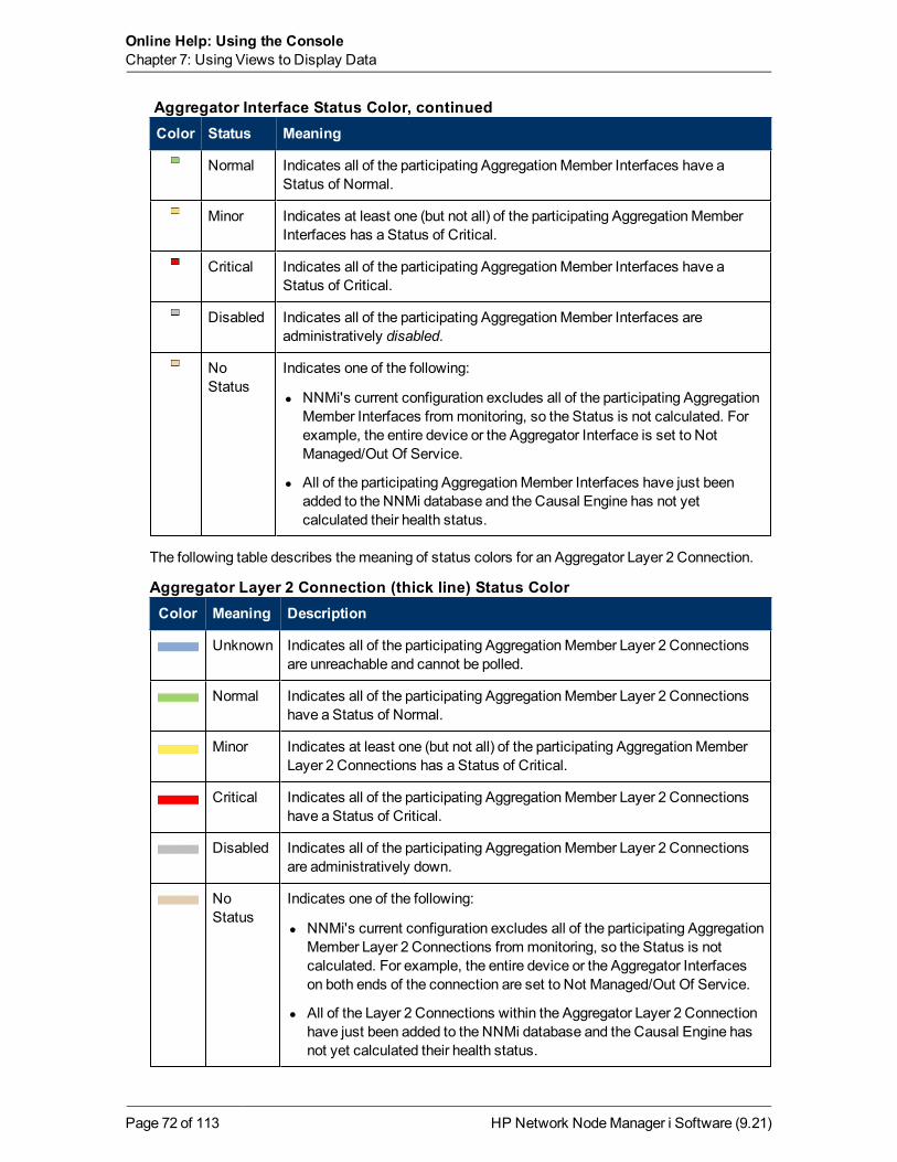
Online Help: Using the ConsoleChapter 7: Using Views to Display Data
Color Status Meaning
Normal Indicates all of the participating AggregationMember Interfaces have aStatus of Normal.
Minor Indicates at least one (but not all) of the participating AggregationMemberInterfaces has a Status of Critical.
Critical Indicates all of the participating AggregationMember Interfaces have aStatus of Critical.
Disabled Indicates all of the participating AggregationMember Interfaces areadministratively disabled.
NoStatus
Indicates one of the following:
l NNMi's current configuration excludes all of the participating AggregationMember Interfaces frommonitoring, so the Status is not calculated. Forexample, the entire device or the Aggregator Interface is set to NotManaged/Out Of Service.
l All of the participating AggregationMember Interfaces have just beenadded to the NNMi database and the Causal Engine has not yetcalculated their health status.
Aggregator Interface Status Color, continued
The following table describes themeaning of status colors for an Aggregator Layer 2 Connection.
Color Meaning Description
Unknown Indicates all of the participating AggregationMember Layer 2 Connectionsare unreachable and cannot be polled.
Normal Indicates all of the participating AggregationMember Layer 2 Connectionshave a Status of Normal.
Minor Indicates at least one (but not all) of the participating AggregationMemberLayer 2 Connections has a Status of Critical.
Critical Indicates all of the participating AggregationMember Layer 2 Connectionshave a Status of Critical.
Disabled Indicates all of the participating AggregationMember Layer 2 Connectionsare administratively down.
NoStatus
Indicates one of the following:
l NNMi's current configuration excludes all of the participating AggregationMember Layer 2 Connections frommonitoring, so the Status is notcalculated. For example, the entire device or the Aggregator Interfaceson both ends of the connection are set to Not Managed/Out Of Service.
l All of the Layer 2 Connections within the Aggregator Layer 2 Connectionhave just been added to the NNMi database and the Causal Engine hasnot yet calculated their health status.
Aggregator Layer 2 Connection (thick line) Status Color
HP Network NodeManager i Software (9.21)Page 72 of 113

Online Help: Using the ConsoleChapter 7: Using Views to Display Data
Related Topics
"Status Color for Objects" (on page 68)
About Map Symbols
Map symbols represent nodes or node groups. Eachmap symbol that represents a single node hasa background shape and a superimposed foreground image (default images shown in the tablebelow). Custom foreground images might represent specific vendors andmodels. The backgroundshape conveys the following information:
l The type of device.
l Themost recent health status (see "About Status Colors" (on page 68)).
l All connections:
n In Layer 2 Neighbor View maps, as well as NodeGroup or Path View maps using Layer 2connectivity, small squares around the parent symbol represent each connected interface.Lines of a normal thickness indicate one-to-one connections. Special icons indicate one-to-many connections.
NNMi Advanced. Thick lines between Interface icons represent Aggregator Layer 2Connections between Aggregator Interfaces using Link Aggregation1 protocol. SeeInterface Form: Link Aggregation tab.
n In Layer 3 Neighbor View maps, as well as NodeGroupmaps using Layer 3 connectivity,small hexagons around the parent symbol represent each connected address. Lines indicateone-to-one connections. Special icons indicate subnets or clouds.
n In all maps, except Path View, thick lines between Node icons or between NodeGroup iconsindicate that multiple connections exist between the objects. NNMi uses the termmulticonnection2 to refer to these groups of multiple connections.
Note the following about multiconnections:
o No Interface or IP address icon appears at either end of the thick line.
o To view the individual connections and the associated interfaces within amulticonnection,double-click themulticonnection of interest.
1Protocols used on Switches to configuremultiple Interfaces (AggregationMember Interfaces) tofunction as if they were one (an Aggregator Interface). When two Aggregator Interfaces establish aconnection, that connection is an Aggregator Layer 2 Connection. The Aggregator Layer 2Connection appears on Layer 2 Neighbor View maps as a thick line with an Interface icon at eachend (representing the Aggregator Interface). When you double-click the thick line, it converts intomultiple thin lines representing the participating AggregationMember Layer 2 Connections with theirAggregationMember Interfaces at each end of the lines.2A multiconnection is a thick line on amap view between two Node icons, two NodeGroup icons,or between a Node icon and a NodeGroup icon (with no Interface icon or IP Address icon at eitherend of the line). This thick line represents a set of multiple connections that have been combined topreserve space and simplify themap. Your NNMi administrator specifies the number ofconnections that must exist before NNMi condenses them into amulticonnection line (UserInterface Configuration's Multiconnection Threshold attribute). Double-click the thick line to convertit into the original set of connections with Interface icons or IP Address icons at either end of thelines.
HP Network NodeManager i Software (9.21)Page 73 of 113

Online Help: Using the ConsoleChapter 7: Using Views to Display Data
o To collapse the expanded view of the individual connections for amulticonnection, use theRefresh icon to refresh themap.
o To view summary information about themulticonnection, place themouse cursor over themulticonnection of interest.
n In Path View maps, a black arrow or empty black circle at the end of a connection indicatesthat NNMi was not able to determine a status value because the connection or interface is notin the NNMi database. Reasons a connection or interface are not stored in the NNMidatabase include the following:
o NNMi is unable to collect information about a node in the path because it is a non-SNMPnode.
o A node in the path is not managed by NNMi.
o The discovery information for a node is not up-to-date (for example, interface information ismissing).
Each Child NodeGroup has a narrow hexagon background shape and does not include a foregroundimage.
Note: You can integrate NNMi with other applications, including HP Network NodeManager iSoftware Smart Plug-ins (iSPIs). The NNMi administrator is also able to customize NNMiforeground images. Therefore, youmight see foreground shapes that are not described in thefollowing table. Contact your NNMi administrator if you have questions about any additionalforeground shapes.
BackgroundShape
Foreground Shape \Meaning
BackgroundShape
Foreground Shape \Meaning
= Chassis = Computer = Server = Workstation = Other
Note: Other includes non-SNMP nodes.
= Analyzer = Firewall = Load Balancer = Network Appliance = Power Supply = Printer = Wireless Access
Point
= ATM Switch = Switch
= Gateway = Hub = Router = Switch-Router = Voice Gateway
Child NodeGroup = IP Phone
Network
Background and Foreground Shapes for Specific Devices
HP Network NodeManager i Software (9.21)Page 74 of 113

Online Help: Using the ConsoleChapter 7: Using Views to Display Data
Icon Meaning
Used inmaps to represent Point-to-Multipoint (a connection with multipleinterfaces) when NNMi concludes that a sharedmedia, such as a hub or amesh,connects multiple devices.Click here for an example.
If you double-click the line or the icon, the Layer 2 Connection Form displays.
Used inmaps to represent Point-to-Multipoint (a connection with multiple
interfaces) Layer 3 edge connectivity across wide-area-networks (WANs). Theicon represents an unidentified set of devices between two nodes on themap (mostlikely a Service Provider's network orWAN).Click here for an example.
NNMi accomplishes this by following special rules for subnets with prefix lengthsbetween 28 and 31. These special rules are called Subnet Connection Rules. NNMiadministrators can configure these rules.
If you double-click the line or the icon, the Layer 2 Connection Form displaysand the Topology Source value is SUBNETCONNECTION.
Used inmaps to represent IPv4 subnets.Click here for an example.
(NNMi Advanced) Used inmaps to represent IPv6 subnets.Click here for an
Icons for Special Connections
HP Network NodeManager i Software (9.21)Page 75 of 113

Online Help: Using the ConsoleChapter 7: Using Views to Display Data
Icon Meaning
example.
Used in Path Views. If NNMi detects a connection, but cannot verify the device'sidentification (no response to SNMP), that device is indicated on themap by a cloudsymbol.Click here for an example.
Note: In Path View maps, a black arrow or empty black circle indicates that NNMiwas not able to determine a status value because the connection or interfaceis not in the NNMi database.
(NNMi Advanced) If the Router Redundancy Group has more than one Activerouter, NNMi selects one Active router for the path. To indicate there is more thanone possible path, NNMi connects any additional Active routers to the chosenrouter as shown in the following example:
(NNMi Advanced) If your network administrator configures NNMi to gather datafrom HP Route Analytics Management Systems (RAMS), the Path View can showmultipleOSPF1 Equal Cost paths through a Layer 3 cloud as shown in the examplebelow:
Icons for Special Connections, continued
1Open Shortest Path First Protocol
HP Network NodeManager i Software (9.21)Page 76 of 113

Online Help: Using the ConsoleChapter 7: Using Views to Display Data
Icon Meaning
(NNMi Advanced) Used in RAMS MPLSWAN Map views. If NNMi detects anMPLS connection across the network, it is indicated on themap by a cloudsymbol.Click here for an example.
Icons for Special Connections, continued
Related Topics
"Working with Objects" (on page 96)
Node Group Map Objects
Tip: See "Help for Operators" for more information about NodeGroupmaps.
NodeGroupmaps show members of a NodeGroup (as defined by the NNMi administrator). EachNodeGroupMap shows either Layer 2 or Layer 3 information.
Themap displays the status of eachmember, connection, and Child NodeGroup. To providecontext for your environment, the NNMi administrator might also add a background image (forexample, amap of North America).
NNMi can enlarge themap symbol of any node associated with aKey Incident1. Use the IndicateKey Incidents button in themap view toolbar (see Using the View Toolbars: NodeGroupMapToolbar Icons):
(on) = When the this NodeGroupmap opens, NNMi enlarges any objects on a NodeGroupmap that are Source Objects for aKey Incident2. (For example, when viewing the Node
1Incidents with both: (1) Severity = other than Normal. (2) Correlation Nature = equal to RootCause, Service Impact, Stream Correlation, Rate Stream Correlation, Info, or None.2Incidents with both: (1) Severity = other than Normal. (2) Correlation Nature = equal to RootCause, Service Impact, Stream Correlation, Rate Stream Correlation, Info, or None.
HP Network NodeManager i Software (9.21)Page 77 of 113

Online Help: Using the ConsoleChapter 7: Using Views to Display Data
Groupmap, NNMi enlarges any node on a NodeGroupmap that has an open root causeincident associated with it.)
(off) = When the this NodeGroupmap opens, NNMi does not indicate the objects on a NodeGroupmap that are Source Objects for aKey Incident1.
To view the associated incident for the node, double-click the node symbol. In the Node form,select the Incidents tab.
Because thesemaps are based on NodeGroups rather than connectivity, some nodes might nothave any connections on themap.
A hexagon (as shown below) indicates a Child NodeGroup:
See "Views Provided by NNMi" (on page 85) for information about the NodeGroupmaps that NNMiprovides.
Related Topics
"About Map Symbols" (on page 73)
"About Status Colors" (on page 68)
Layer 2 Neighbor View Map Objects
Layer 2 Neighbor View maps show amap view of a selected device and any connected deviceswithin a specified number of hops from the selected device. This view is useful for understandingthe switch connectivity between devices. See "Help for Operators" for more information.
During discovery, NNMi reads the Forwarding Database (FDB) tables from Ethernet switcheswithin a network to help NNMi determine communication paths between network devices. NNMisearches these FDB tables for information about discovered nodes. When an NNMi managementserver finds FDB references to duplicateMAC addresses2:
l If two or more discovered nodes contain an interface associated with the sameMedia AccessControl (MAC) address within the same Tenant or with one of those nodes in Default Tenant andone in any other Tenant, NNMi disregards the communication paths reported for those duplicateMAC addresses in the FDB. This might result in missing connections on NNMi maps in networkareas that include those duplicate MAC addresses.
(NNMi Advanced - Global Network Management feature) If two NNMi management serversdiscover nodes that contain an interface associated with the sameMedia Access Control (MAC)address, the Global NNMi management server's maps could bemissing connections that arevisible on the Regional NNMi management server's maps.
1Incidents with both: (1) Severity = other than Normal. (2) Correlation Nature = equal to RootCause, Service Impact, Stream Correlation, Rate Stream Correlation, Info, or None.2TheMedia Access Control address (hardware address or physical address) that the factory burnsinto a network adapter or device with built-in networking capability. A MAC address has six pairs ofhexadecimal digits, separated by colons or dashes. For example 02:1F:33:16:BC:55
HP Network NodeManager i Software (9.21)Page 78 of 113

Online Help: Using the ConsoleChapter 7: Using Views to Display Data
l If a single node contains multiple interfaces that have the sameMAC address, NNMi gathers allcommunication path information for those interfaces and displays that information on NNMimaps.
Forwarding Database (FDB) information can cause NNMi to establish wrong Layer 2 Connectionsin the following cases:
l When the FDB is configured as cache and contains obsolete data.
l In network environments with hardware from a variety of vendors, when each vendor generatesdifferent and sometimes conflicting FDB data.
Optional: NNMi administrators can configure Spiral Discovery to ignore the FDB data from oneNodeGroup when calculating Layer 2 Connections (the FDB data is still included in othercalculations).
In Layer 2 Neighbor View maps, interfaces are indicated by little squares around the backgroundshape of the parent node. Each interface also has a status color. Green indicates the interface isworking properly. Red indicates the interface is down.
Connection Lines Meaning of Connection Line
Thin lines between devices indicate communication channelsbetween the two devices (connections). The lines also show statuscolor indicating the current health of that connection. See "StatusColor for Objects" (on page 68).
NNMi Advanced. Thick lines (connections) indicate that LinkAggregation1 protocols are in use. These protocols enablenetwork administrators to configure a set of interfaces on a switchas one Aggregator Interface, creating an Aggregator Layer 2Connection to another device usingmultiple interfaces in parallel toincrease bandwidth, increase the speed at which data travels, andincrease redundancy.
Double-click the thick line (the Aggregator Layer 2 Connection) toconvert the thick line into multiple thin lines. Each thin linerepresents an AggregateMember Layer 2 Connection.
NNMi calculates the status of the thick line (Aggregator Layer 2Connection) based on the status of the entire group of AggregationMember Layer 2 Connections. See "Status Color for AggregatorObjects (NNMi Advanced)" (on page 71) for more information.
1Protocols used on Switches to configuremultiple Interfaces (AggregationMember Interfaces) tofunction as if they were one (an Aggregator Interface). When two Aggregator Interfaces establish aconnection, that connection is an Aggregator Layer 2 Connection. The Aggregator Layer 2Connection appears on Layer 2 Neighbor View maps as a thick line with an Interface icon at eachend (representing the Aggregator Interface). When you double-click the thick line, it converts intomultiple thin lines representing the participating AggregationMember Layer 2 Connections with theirAggregationMember Interfaces at each end of the lines.
HP Network NodeManager i Software (9.21)Page 79 of 113

Online Help: Using the ConsoleChapter 7: Using Views to Display Data
Connection Lines Meaning of Connection Line
Note: A thick line that does not have any interface icon at bothends is amulticonnection1, instead of an Aggregator Layer 2Connection.
See "Help for Operators" for more information about Layer 2 Neighbor View maps.
Related Topics
"About Map Symbols" (on page 73)
"About Status Colors" (on page 68)
Layer 3 Neighbor View Map Objects
Layer 3 Neighbor View maps show a selected device and its connected devices within a specifiednumber of hops from the selected device. This view is useful for understanding the routerconnectivity between devices.
In Layer 3 Neighbor View maps, addresses connected to neighbors within the same subnet areindicated by hexagons around the background shape of the parent node. Each address has a statuscolor. Green indicates the address is working properly. Red indicates the address is notresponding. The line between devices indicates the subnet. The subnet does not have any status:
NNMi Advanced. IPv6 subnets are indicated by this symbol:
See "Help for Operators" for more information about Layer 3 Neighbor View maps.
1A multiconnection is a thick line on amap view between two Node icons, two NodeGroup icons,or between a Node icon and a NodeGroup icon (with no Interface icon or IP Address icon at eitherend of the line). This thick line represents a set of multiple connections that have been combined topreserve space and simplify themap. Your NNMi administrator specifies the number ofconnections that must exist before NNMi condenses them into amulticonnection line (UserInterface Configuration's Multiconnection Threshold attribute). Double-click the thick line to convertit into the original set of connections with Interface icons or IP Address icons at either end of thelines.
HP Network NodeManager i Software (9.21)Page 80 of 113

Online Help: Using the ConsoleChapter 7: Using Views to Display Data
Related Topics
"About Map Symbols" (on page 73)
"About Status Colors" (on page 68)
Path View Map Objects
Path View maps show an active network path between a source and destination end point.
Themain objects in the displayed path in a Path View map are routers and switches.
Caution: Do not specify a switch as a Source or Destination node in Path View maps. To viewconnectivity between switches, use the Layer 2 Neighbor View.
When NNMi cannot determine the nodes within a portion of the path, it uses a Cloud object asshown in the example below:
If a black arrow or empty black circle appears at the end of the connection in Path View maps,NNMi was not able to determine a status value because the connection or interface is not in theNNMi database. Click here for more information.
Reasons a connection or interface are not stored in the NNMi database, include the following:
l NNMi is unable to collect information about a node in the path because it is a non-SNMP node.
l A node in the path is not managed by NNMi.
l The discovery information for a node is not up-to-date (for example, interface information ismissing).
Path View maps also show objects included in Layer 2 Neighbor View maps and Layer 3 NeighborView maps. See "Help for Operators" for more information.
NNMi Advanced. Path View works only with IPv4 addresses. The NNMi Advanced IPv6 addressvalues are not valid choices for Path View. Any devices in your network that are configured withIPv6 addresses cannot be displayed on Path View maps.
(NNMi Advanced) If your network administrator configures NNMi to gather data from RouterRedundancy Groups that havemore than one Active router, NNMi selects one Active router for thepath. To indicate there is more than one possible path, NNMi connects any additional routers to theActive router as shown in the example below:
HP Network NodeManager i Software (9.21)Page 81 of 113

Online Help: Using the ConsoleChapter 7: Using Views to Display Data
(NNMi Advanced) If your network administrator configures NNMi to gather data from RouteAnalytics Management Systems (RAMS), the Path View can show multipleOSPF1 Equal Costpaths through a Layer 3 cloud as shown in the example below:
Related Topics:
"About Map Symbols" (on page 73)
"About Status Colors" (on page 68)
Access Maps Provided by NNMiYou can access maps in the following ways:
l From table views using theActionsmenu
l From the Topology Maps and Troubleshooting workspaces
Table Views
To display amap view from a table view:
See "Using Actions to Perform Tasks" (on page 100) for more information about using the Actionsmenu.
1. Select the table view you want from the workspaces navigation panel. (For example, select theInventory workspace, Nodes view.)
2. In the table view, click the row that contains the object of interest.
3. Select theActions menu in themain toolbar and select themap view you want.
1Open Shortest Path First Protocol
HP Network NodeManager i Software (9.21)Page 82 of 113

Online Help: Using the ConsoleChapter 7: Using Views to Display Data
Note: You can also access map views from theActionsmenu in a form. See "About the NNMiConsole" (on page 9), for more information.
Tip: You can right-click any object in a table or map view to access theActionsmenu.
The label for the starting node appears in bold text on themap.
4. If you are displaying either Layer 2 or Layer 3 Neighbor View maps, after themap viewappears, you can change the number of hops1.
In theNumber of Hops drop-down list, select the number of hops to display. The defaultnumber of hops is 1. Themaximum number of hops is 9.
Topology Maps Workspace
To display a NodeGroupmap:
1. Select the Topology Mapsworkspace.
2. Select Node Group Map name of interest.
Troubleshooting Workspace
l To display a Layer 2 or Layer 3 Neighbor View map:
a. Select the Troubleshooting workspace.
b. Select the type of map you want to generate.
c. In Layer 2 Neighbor View and Layer 3 Neighbor View maps, you can designate the startingnode using either the node name or IP address. The label for the starting node appears inbold text on themap.
Note: After you begin to type the node name or IP address, NNMi displays a list thatincludes all potential existing names or IP addresses that match the letters or numbersas you enter them.
d. After themap view appears, you can change the number of hops2.
In theNumber of Hops drop-down list, select the number of hops to display. The defaultnumber of hops is 1. Themaximum number of hops is 9.
1A hop is a node representing any network device, such as a workstation, gateway, or switch,which is connected by a link with no intermediate nodes.2A hop is a node representing any network device, such as a workstation, gateway, or switch,which is connected by a link with no intermediate nodes.
HP Network NodeManager i Software (9.21)Page 83 of 113

Online Help: Using the ConsoleChapter 7: Using Views to Display Data
l To display a Path View:
a. Select the Troubleshooting workspace.
b. Select Path View.
c. In theSource andDestination fields, designate the nodes at both ends of the path usingeither the node name or IPv4 address.
Note: After you begin to type the node name or IPv4 address, NNMi displays a list thatincludes all potential existing names or IPv4 addresses that match the letters ornumbers as you enter them.
NNMi Advanced. Path View works only with IPv4 addresses. The NNMi Advanced IPv6address values are not valid choices for Path View. Any devices in your network that areconfigured with IPv6 addresses cannot be displayed on Path View maps.
l To display a NodeGroupmap:
a. Select the Troubleshooting workspace.
b. Select Node Group Map.
c. In the NodeGroup field, specify the name of the NodeGroup that contains the nodes youwant to display.
Note: After you begin to type the NodeGroup name, NNMi displays a list that includesall potential existing names (case-sensitive) that match the letters or numbers as youenter them.
HP Network NodeManager i Software (9.21)Page 84 of 113

Chapter 8
Views Provided by NNMiNNMi offers several out-of-the-box views to determine amanaged device's status. Each of these isdescribed in the following tables.
Note: Depending on your NNMi user role, youmight not be able to see all of the viewsdescribed.
l Views for Incident Management
l Views of Topology Maps
l Views to Assist You with Monitoring Network Devices
l Views to Assist You with Troubleshooting
l Views with Inventory Lists
l Management Mode Views
l Views for Incident Browsing
View Title Description
Open KeyIncidents
Shows the incidents that aremost important to network Operators (any KeyIncident1) and that often require more immediate action. TheOpen Key Incidentsview includes those incidents that have a Correlation Nature that is any of thefollowing:
IncidentCorrelationNature Description
RootCause
Indicates the incident that reports the root cause of a problem.
ServiceImpact
Used in NNMi 8.xx only. Indicates a relationship betweenincidents in which a network service is effected by otherincidents. By default, NNMi generates Service Impact incidentsfor Router Redundancy Groups. For example, an Interface Downincident can effect a Router Redundancy Group that is part of anHSRP service. The Service Impact incident helps to identify theservice that is affected.
Views for Incident Management
1Incidents with both: (1) Severity = other than Normal. (2) Correlation Nature = equal to RootCause, Service Impact, Stream Correlation, Rate Stream Correlation, Info, or None.
HP Network NodeManager i Software (9.21)Page 85 of 113

Online Help: Using the ConsoleChapter 8: Views Provided by NNMi
View Title Description
IncidentCorrelationNature Description
This Correlation Nature is available for use by HP Network NodeManager i Software Smart Plug-ins (iSPIs). See "Help forAdministrators" for more information about NNM iSPIs.
StreamCorrelation
Used in NNMi 8.xx only. Indicates the correlations that NNMi'sevent pipeline establishes as it recognizes patterns in the flow ofevents through the pipeline. Correlations are created as NNMianalyzes events and traps to determine the root cause incident fora problem. Examples of stream correlations include Dedup(duplication of events) and Rate (occurrence of events by time)correlations.
RateStreamCorrelation
Indicates the incident tracks incident patterns based on thenumber of incident reoccurrences within a specified time period.After the count within the specified time period is reached,NNMi emits a Rate Correlation incident and continues to updatethe Correlation Notes with the number of occurrences within thatrate.
Info This Correlation Nature is meant to be informational.
None Indicates there is no incident correlation for this incident.
UnassignedOpen KeyIncidents
Shows any openKey Incident1 that has not yet been assigned. This view isuseful for identifying themost recent Key Incidents that must be assigned.
My OpenIncidents
Shows the incidents that have been assigned to the name associated with thecurrent user.
Views for Incident Management, continued
View Title Description
NodeGroupOverview
Displays amap containing all (top-level) NodeGroups that do not have parentNodeGroups.
InitialDiscovery Tip: Create a NodeGroupmap tomonitor your network topology. See
Views of Topology Maps (See "Help for Operators" for more information aboutNode Group Maps.)
1Incidents with both: (1) Severity = other than Normal. (2) Correlation Nature = equal to RootCause, Service Impact, Stream Correlation, Rate Stream Correlation, Info, or None.
HP Network NodeManager i Software (9.21)Page 86 of 113

Online Help: Using the ConsoleChapter 8: Views Provided by NNMi
View Title Description
Progress(Layer 3) Create NodeGroups for information about NodeGroups..
Displays amap containing themost highly connected nodes (largest subnets) inthe Layer 3 network. Use this map to display the initial discovery progress of theRouters, Switches, and Switch-Routers, for up to 100 nodes.
Note: NNMi displays this map only if the NNMi administrator has configuredthe NNMi console's Initial View to be Installation Default and the networkhas less than or equal to a total of 100 routers, switches, and switch-routers.After NNMi has discoveredmore than 100 connectors, this map viewchanges to the Open Key Incidents table view.
To determine which nodes to display, NNMi uses the following algorithm until ithas displayed amaximum of 100 nodes:
l Display the largest subnets (Layer 3 connectivity) based on discoveredrouters
l Display themost highly connected switches within the subnets displayed
l Display themost highly connected nodes within the subnets displayed
l Display any remaining nodes up to a total of 100
Note the following:
l NNMi polls only management IP addresses by default. Therefore, the statusof IP addresses on themapmight appear as No Status ( ).
l Because the connections on a Layer 3 represent subnets, which are notmonitored in NNMi, the connections on a the Initial Discovery Progress mapappear as No Status ( ).
l The Initial Discovery Progressmap displays amaximum of 100 nodes. Thismaximum number cannot be changed.
This map periodically updates both topology and status. The update interval ismore frequent when the view is first displayed by any user, then slowly refreshesless frequently.
Note: Automatic refresh cancels any modifications, such as selecting orzooming, youmake to this view.
To view the Layer 2 (switch) connectivity for a particular node, select the node ofinterest and use theActions→ Layer 2 Neighbor View. To view the Layer 3(router) connectivity for a particular node, select the node of interest and useActions→ Layer 3 Neighbor View.
Views of Topology Maps (See "Help for Operators" for more information aboutNode Group Maps.), continued
HP Network NodeManager i Software (9.21)Page 87 of 113

Online Help: Using the ConsoleChapter 8: Views Provided by NNMi
View Title Description
Tip: You can right-click any object in a table or map view to access theActionsmenu.
NetworkOverview(Layer 3)
This map is similar to the Initial Discovery Progressmapwith the followingexceptions:
l Network Overview displays amap containing themost highly connectednodes (largest subnets) in the Layer 3 network for up to 250 nodes.
l The NNMi administrator can change themaximum number of nodesdisplayed. If you are an NNMi administrator, for more information, see the"NNMi Console" chapter in theHP Network NodeManager i SoftwareDeployment Reference, which is available at:http://h20230.www2.hp.com/selfsolve/manuals.
l The refresh rate is 5minutes.
l The NNMi administrator must have configured the NNMi console's InitialView to beNetwork Overview.
NetworkingInfrastructureDevices
Displays representative NodeGroups for the Switches and for the Routers inyour network. Each of the following device types, if applicable, are also includedon themap:
l Chassis
l Firewalls
l Voice Gateways
Note: Your NNMi Administrator can remove this map from the TopologyMaps workspace.
See "Help for Operators" for more information about NodeGroupMaps.
Routers Displays a NodeGroupMap of the Router and Layer 3 connectivity in yournetwork.
Tip: See "About Node and Interface Groups" (on page 49) for moreinformation about NodeGroups.
Note: If the number of NodeGroups in your network is greater than themaximum number of map objects configured to be displayed on themap,NNMi filters themap to display routers that have interfaces with addressesin the largest number of overall subnets in the network.
Your NNMi administrator can configure themaximum number of nodes to be
Views of Topology Maps (See "Help for Operators" for more information aboutNode Group Maps.), continued
HP Network NodeManager i Software (9.21)Page 88 of 113

Online Help: Using the ConsoleChapter 8: Views Provided by NNMi
View Title Description
displayed on amap. See "Help for Administrators" for more information.
Note: Your NNMi Administrator can remove this map from the TopologyMaps workspace.
Switches Displays a NodeGroupmap of the Switches and Layer 2 connectivity in yournetwork.
Tip: See "About Node and Interface Groups" (on page 49) for moreinformation about NodeGroups.
Note: If the number of nodes in your network is greater than themaximumnumber of nodes configured to be displayed on themap, NNMi filters themap to display switches that are themost highly connected.
Your NNMi administrator can configure themaximum number of nodes to bedisplayed on amap. See "Help for Administrators" for more information.
Note: Your NNMi Administrator can remove this map from the TopologyMaps workspace.
Views of Topology Maps (See "Help for Operators" for more information aboutNode Group Maps.), continued
View Title Description
Non-NormalNodeComponents
Identifies the nodes that might need operator attention due to a problem with thehealth of a node component.
Non-NormalCards
Identifies the cards that might need operator attention.
Non-NormalInterfaces
Identifies all of the interfaces that might need operator attention.
Non-NormalNodes
Identifies all of the nodes that might need operator attention.
Non-NormalSNMPAgents
identifies all of the SNMP Agents that have a state that is other than Normal.
NotResponding
Identifies all of the addresses that have a state of Not Responding. A NotResponding state indicates that the address is not responding to ICMP ping.
Views to Assist You with Monitoring Network Devices
HP Network NodeManager i Software (9.21)Page 89 of 113

Online Help: Using the ConsoleChapter 8: Views Provided by NNMi
View Title Description
Addresses
InterfacePerformance
(HP Network NodeManager iSPI Performance for Metrics Software) Helps youidentify the over-used and under-used interfaces for the nodes in your managednetwork.
CardRedundancyGroups
Shows the Card Redundancy Groups that NNMi discovered.
See "Help for Operators" for more information about Card Redundancy Groups.
RouterRedundancyGroups
Shows the available Router Redundancy Groups created by the NNMiadministrator. Each Router Redundancy Group is a set of two or more routersthat use one or more virtual IP addresses to help ensure that information packetsreach their intended destination.
See "Help for Operators" for more information about Router RedundancyGroups.
NodeGroups Shows the NodeGroups created by the NNMi administrator. NodeGroupsenable the NNMi administrator to define groups of nodes based on severalcriteria, including by hostname or location.
See "About Node and Interface Groups" (on page 49) for more information aboutNodeGroups.
Custom NodeCollections
Shows the Custom Node Collections that have been created using NNMi'sCustom Poller. A Custom Node Collection identifies a topology node that has atleast one associated Custom Poller Policy.
See "Help for Operators" for more information about Custom Node Collections.
CustomPolledInstances
Shows the Custom Polled Instances that have been created using NNMi'sCustom Poller. NNMi creates Custom Polled Instances the first time aMIBExpression is validated with discovery information.
See "Help for Operators" for more information about Custom Polled Instances.
Views to Assist You with Monitoring Network Devices, continued
ViewTitle Description
Layer 2NeighborView
Shows amap view of a selected device and its connector devices within a specifiednumber of hops from the selected device. This view is useful for understanding theswitch connectivity between devices.
The background color of a node in a network map indicates the node's or interface'sstatus. For example, green indicates the node is up. Red indicates the node orinterface is down.
Views to Assist You with Troubleshooting
HP Network NodeManager i Software (9.21)Page 90 of 113

Online Help: Using the ConsoleChapter 8: Views Provided by NNMi
ViewTitle Description
Layer 3NeighborView
Shows amap view of a selected device and it connector devices within a specifiednumber of hops from the selected device. This view is useful for understanding therouter connectivity between devices.
The background color of a node in a network map indicates the node's or interface'sstatus. For example, green indicates the node is up. Red indicates the node orinterface is down.
PathView
Shows an active network path between a source and destination end point.
Caution: Do not specify a switch as a Source or Destination node in Path Viewmaps. To view connectivity between switches, use the Layer 2 Neighbor View.
This view is useful for diagnosing connectivity problems; for example, when one nodecannot communicate with another or when you are not able to access a particularnode, such as a client PC not being able to contact theMicrosoft Exchange server.
Note: NNMi Advanced. Path View works only with IPv4 addresses. The NNMiAdvanced IPv6 address values are not valid choices for Path View. Any devicesin your network that are configured with IPv6 addresses cannot be displayed onPath View maps.
NodeGroupMap
Shows the pre-definedmembers of a NodeGroup in the context of not only status andconnectivity, but of a pre-defined background image (for example, amap of NorthAmerica).
See "Help for Operators" for more information about NodeGroupMaps.
Views to Assist You with Troubleshooting, continued
View Title Description
Nodes Shows the status for all nodes discovered by NNMi.
Sorting this view by status lets you see all of the nodes that are down orsomehow disabled.
Interfaces Shows the information about all network interfaces discovered by NNMi.
Sorting this view by associated node Name value (Hosted on Node) lets you seeall of the network interfaces per node.
Sorting the view by Administrative or Operations Status helps you determine theinterfaces or nodes that are down or somehow disabled.
IPAddresses
Shows the status for all IP addresses hosted on Nodes that are discovered byNNMi. (The Node form: IP Addresses tab also displays relevant addresses from
Views with Inventory Lists
HP Network NodeManager i Software (9.21)Page 91 of 113

Online Help: Using the ConsoleChapter 8: Views Provided by NNMi
View Title Description
this view.)
IP Subnets Shows the status for all IP subnets.
Sorting this view by status lets you quickly see all of the IP addresses that have astatus that indicates there is a current or potential problem.
VLANs Shows the switch port VLANs discovered in your network environment. A devicecan participate in multiple VLANs. And a port can be assigned tomultiple VLANs.
Cards Shows the cards NNMi discovered in your network environment.
Ports Shows the ports NNMi discovered in your network environment.
NodeComponents
Layer 2Connections
Shows the Layer 2 connections discovered or added in your networkenvironment.
Nodes byManagementServer
(NNMi Advanced) Whenmultiple NNMi management servers share the workloadin your network environment, this view lets you identify which nodes each NNMimanagement server is responsible for discovering andmonitoring.
Nodes (AllAttributes)
Provides a Node view of most Node attributes. Sort and filter this view tomeetyour needs.
Interfaces(AllAttributes)
Provides an Interface view of most Interface attributes. Sort and filter this view tomeet your needs.
IPAddresses(AllAttributes)
Provides an IP Address view of most IP Address attributes. Sort and filter thisview tomeet your needs.
One column shows any currently configuredMapped Addresses. If staticNetwork Address Translation (NAT) is part of your network, your NNMiadministrator can configure NNMi to display the NAT internal IP addressassigned (mapped) to the selected external IP address.
MIBVariables
Shows theMIB variables available from theMIBs that are loaded in the NNMidatabase.
CardRedundancyGroups
Shows the Card Redundancy Groups that NNMi discovered.
See "Help for Operators" for more information about Card Redundancy Groups.
RouterRedundancyGroups
(NNMi Advanced) Shows the available Router Redundancy Groups created bythe NNMi administrator. Each Router Redundancy Group is a set of two or morerouters that use one or more protected (virtual) IP addresses to help ensure thatinformation packets reach their intended destination. See "Help for Operators" for
Views with Inventory Lists, continued
HP Network NodeManager i Software (9.21)Page 92 of 113

Online Help: Using the ConsoleChapter 8: Views Provided by NNMi
View Title Description
more information about Router Redundancy Groups.
RouterRedundancyMembers
(NNMi Advanced) Shows themembers of the Router Redundancy Groupscreated by the NNMi administrator.
NodeGroups
Shows the NodeGroups provided by NNMi and created by the NNMiadministrator.
See "About Node and Interface Groups" (on page 49) for more information aboutNodeGroups.
InterfaceGroups
Shows the Interface Groups provided by NNMi and created by the NNMiadministrator.
See "Help for Operators" for more information about Interface Groups.
ManagementStations(6.x/7.x)
Shows the 6.x/7.x Management Stations that have been configured to forward6.x or 7.x events to NNMi.
MPLSWANClouds(RAMS)
(NNMi Advanced) Shows the information about all MPLS WANs discovered byNNMi.
Views with Inventory Lists, continued
View Title Description
UnmanagedNodes
Shows all of the nodes that have amanagement mode set toNot Managed orOut of Service. These nodes are no longer beingmonitored nor updated.
UnmanagedInterfaces
Shows all of the interfaces that have amanagement mode set toNot ManagedorOut of Service. These interfaces are no longer beingmonitored nor updated.
UnmanagedIP Addresses
Shows all of the addresses that have amanagement mode set toNot ManagedorOut of Service. These addresses are no longer beingmonitored nor updated.
UnmanagedCards
Shows all of the cards that have amanagement mode set toNot Managed orOut of Service. These cards are no longer beingmonitored nor updated.
UnmanagedNodeComponents
Shows all of the node components that have amanagement mode set toNotManaged orOut of Service. These components are no longer beingmonitorednor updated.
Management Mode Views
HP Network NodeManager i Software (9.21)Page 93 of 113

Online Help: Using the ConsoleChapter 8: Views Provided by NNMi
View Title Description
Open KeyIncidents
Shows the incidents that aremost important to network Operators (any KeyIncident1) and that often require more immediate action. TheOpen Key Incidentsview includes those incidents that have a Correlation Nature that is any of thefollowing:
IncidentCorrelationNature Description
RootCause
Indicates the incident that reports the root cause of a problem.
ServiceImpact
Used in NNMi 8.xx only. Indicates a relationship betweenincidents in which a network service is effected by otherincidents. By default, NNMi generates Service Impact incidentsfor Router Redundancy Groups. For example, an Interface Downincident can effect a Router Redundancy Group that is part of anHSRP service. The Service Impact incident helps to identify theservice that is affected.
This Correlation Nature is available for use by HP Network NodeManager i Software Smart Plug-ins (iSPIs). See "Help forAdministrators" for more information about NNM iSPIs.
StreamCorrelation
Used in NNMi 8.xx only. Indicates the correlations that NNMi'sevent pipeline establishes as it recognizes patterns in the flow ofevents through the pipeline. Correlations are created as NNMianalyzes events and traps to determine the root cause incidentfor a problem. Examples of stream correlations include Dedup(duplication of events) and Rate (occurrence of events by time)correlations.
RateStreamCorrelation
Indicates the incident tracks incident patterns based on thenumber of incident reoccurrences within a specified time period.After the count within the specified time period is reached,NNMi emits a Rate Correlation incident and continues to updatethe Correlation Notes with the number of occurrences within thatrate.
Info This Correlation Nature is meant to be informational.
None Indicates there is no incident correlation for this incident.
Closed KeyIncidents
Shows the key incidents that have been closed. This view is useful for identifyingthe root cause incidents that have been resolved. This view might be particularlyuseful for reporting on how many incidents were closed within a given time period.
Views for Incident Browsing
1Incidents with both: (1) Severity = other than Normal. (2) Correlation Nature = equal to RootCause, Service Impact, Stream Correlation, Rate Stream Correlation, Info, or None.
HP Network NodeManager i Software (9.21)Page 94 of 113

Online Help: Using the ConsoleChapter 8: Views Provided by NNMi
View Title Description
OpenRootCauseIncidents
Shows the root cause incidents that have not yet been closed. This view is usefulfor identifying the root cause incidents that need to be resolved.
ServiceImpactIncidents
Indicates incidents that have a relationship to other incidents in which a networkservice is affected. For example, an Interface Down incident can effect a RouterRedundancy Group that is part of an HSRP service. The Service Impact incidenthelps to identify the service that is affected.
This Correlation Nature is available for use by HP Network NodeManager iSoftware Smart Plug-ins (iSPIs).
See "Help for Administrators" for more information about NNM iSPIs.
All Incidents Shows all incidents. This view is useful for determining all of the incidents thathave been generated within a certain time period.
CustomOpenIncidents
Enables you to choose the columns of incident information for all Open incidents,to better meet your needs. For example, youmight want to filter the view todisplay only the incidents related to a particular set of devices. Youmight alsowant to filter the view to display only the incidents assigned to you.
CustomIncidents
Lets you create a customized view for your incident information. For example,youmight want to filter this view to include only the incidents assigned to you.
NNM6.x/7.xEvents
Shows all of the incidents forwarded from Network NodeManager 6.x and 7.xmanagement stations in your network environment.
SNMP Traps Shows all of the traps that were received from devices in your networkenvironment. Your NNMi administrator must configure specific traps before theyare displayed within NNMi incident views
Views for Incident Browsing, continued
Related Topics
"Export Table Information" (on page 61)
HP Network NodeManager i Software (9.21)Page 95 of 113

Chapter 9
Working with ObjectsObjects are database records of information about your environment and events that occur within it.Each type of object represents a particular kind of information. For example, incident objectsrepresent situations or events that arise in your environment.
An object is defined by its attributes. For example, an incident object includes a status attribute anda source node (amongmany others). Different object types have different amounts and types ofattributes. Some attribute values are simple things, such as numbers and text strings. Otherattribute values aremore complex, such as a reference to a related object. For example, when anSNMP Agent attribute appears in a Node form, it represents the SNMP Agent that is related to theselected node.
If more than one of a certain type of object can be related to the selected object (for example,incidents related to a node), the form contains a tab that displays a table with the entire list ofrelated objects.
A view is a collection of related objects that are depicted graphically as a table or map. A formprovides all stored attributes about a selected object. The attributes on the form can be attributes ofthe selected object or related objects.
Operations that can be performed on objects are called actions. Actions are simply shortcuts tosimple or complex tasks. A particular action can be associated with a specific object type. Forexample, when displaying a node table view, youmight want to open amap showing all of thatnode's Layer 2 neighbors.
Tip: You can right-click any object in a table or map view to access theActionsmenu.
To access an object's form from a table view:
Double-click the row representing an object.
NNMi displays the form for the selected object.
To access an object's form from a map view:
Do one of the following:
l Select the node of interest and click the Open icon.
l In most cases, double-click the object of interest.
Note: If themap object is a Child NodeGroup, double-clicking the Child NodeGroup objectreplaces the current map with amap of the nodes in the Child NodeGroup. To access aChild NodeGroup form, select the Child NodeGroup object and click the Open icon.See "Help for Operators" for more information.
NNMi displays the form for the selected object.
A red asterisk (*) that precedes an attribute on a form indicates the attribute requires a value.
HP Network NodeManager i Software (9.21)Page 96 of 113

Online Help: Using the ConsoleChapter 9: Working with Objects
From an object form, you can:
"Modify Object Attribute Values" (on page 98)
"Access All Information About a Related Object" (on page 97)
"Access a Subset of the Available Information About a Related Object" (on page 97)
Access a Subset of the Available Information About aRelated Object
While investigating the available information for an object (within that object's form), someinformation represents attributes of the object itself and some information is about related objects.The related objects are indicated by a Lookup icon. For example, when viewing information foran Interface object, you can access information about the Node in which that interface resides.
A red asterisk (*) that precedes an attribute on a form indicates the attribute requires a value.
This is an example Lookup Field:
To display a subset of information about a related object from within a form:
1. Locate the field for the related object that you want to learnmore about.
2. Click the Lookup icon, and select Show Analysis from the drop-downmenu.
3. The Analysis Pane appears showing information about the related object. See "About theAnalysis Pane" (on page 28) for more information.
Note: NNMi displays only the information that the NNMi Security configuration permitsyou to access. See Determine which NNMi Role to Assign in "Help for Administrators" formore information.
4. Mouse-over any Refresh icon to see the last time the details were updated.
Click any Refresh icon to gather themost recent data.
Access All Information About a Related ObjectWhile investigating the details for one object using a form, you can access information aboutanother related object. For example, when viewing all information stored for a node, you can accessall available information for an interface for that node to determine the interface status.
A red asterisk (*) that precedes an attribute on a form indicates the attribute requires a value.
You can open another form from within a form for any object that is contained in the form you areviewing. Such objects are indicated using a Lookup icon.
This is an example Lookup Field:
HP Network NodeManager i Software (9.21)Page 97 of 113

Online Help: Using the ConsoleChapter 9: Working with Objects
To open another form from within a form:
1. Locate the field of an object about which you want to seemore information.
2. Click the Lookup icon, and select Open from the drop-downmenu.
A new form appears showing all of the attributes for that object. Any default values specified for theobject are pre-populated in the form
Modify Object Attribute ValuesWhen viewing details for an object, such as a node, subnet, or interface, you can change one ormore of its attribute values. For example, you can add notes to an incident to explain steps thatwere taken to date to resolve the problem. Until the problem is resolved you can enter informationrelated to a workaround. Finally, after a solution is determined, you can add information describinghow the problem was resolved.
Note: If you haveGuest user role, you cannot modify any attributes.
Two kinds of fields indicate that you canmodify an attribute.
A red asterisk (*) that precedes an attribute on a form indicates the attribute requires a value.
To modify information in a text box:1. Move your cursor to themodifiable field of interest.
2. Type the new value. For example, the Notes attribute is amodifiable field:
Tip: If the attribute appears to be amodifiable field, but it does not permit text entry, it is amemo field.
Tip: Click the attribute label to access a dialog box that enables you to view or edit text. Usingthis feature, you can insert more text or view a text field that is longer than the originaldisplay area.
3. When you are finished with your edits:
n Click Save to save your changes.
n Click Save and Close to save your changes and close the form.
To modify information in a Lookup field:
1. Look for this icon to the right of a text box . For example:
HP Network NodeManager i Software (9.21)Page 98 of 113

Online Help: Using the ConsoleChapter 9: Working with Objects
2. Do one of the following:
n Start to type into the text box. NNMi displays a list of all valid choices. You can select fromthe list to complete your choice.
n Click the Lookup icon, and choose Quick Find to display a list of valid choices:
3. When you are finished with your edits:
n Click Save to save your changes.
n Click Save and Close to save your changes and close the form.
HP Network NodeManager i Software (9.21)Page 99 of 113

Chapter 10
Using Actions to Perform TasksActions let you perform operations on selected items. The actions available to you depend on yourNNMi user role. Administrators havemore action choices than operators. If SPIs are installed inyour environment, the list of actions could expand.
See the NNMi Actions table for a description of possible actions.
Note: Actions that change an object's attribute value or that require log on access to a node(for example, telnet) are also not included in this list.
Tip: You can right-click any object in a table or map view to access theActionsmenu.
To perform any of the actions described, you select an action from theActionsmenu. TheActionsmenu is accessible from the NNMi consolemainmenu bar and from themenu bar in any form orview that is opened in a new window. See "Invoke Actions" (on page 19) for more information abouthow to access actions.
Tip: You can right-click any object in a table or map view to access theActionsmenu.
Action Description
Layer 2 NeighborView
Maps→ Layer 2 Neighbor View
Displays amap of the Layer 2 network. Layer 2maps help you betterunderstand your switch connectivity. See "Help for Operators" for moreinformation.
Layer 3 NeighborView
Maps→ Layer 3 Neighbor View
Displays amap of the Layer 3 network. Layer 3 network maps help you betterunderstand your router connectivity. See "Help for Operators" for moreinformation.
Path View Maps→ Path View
Displays amap showing the route between two specified nodes. The Sourceand Destination nodes should not be switches.
Note: NNMi Advanced. Path View works only with IPv4 addresses. TheNNMi Advanced IPv6 address values are not valid choices for PathView. Any devices in your network that are configured with IPv6addresses cannot be displayed on Path View maps.
NNMi Actions
HP Network NodeManager i Software (9.21)Page 100 of 113

Online Help: Using the ConsoleChapter 10: Using Actions to Perform Tasks
Action Description
MPLSWANClouds Map
(NNMi Advanced) Displays amap of the Layer 3 connectivity acrossMPLS WAN Clouds. See "Help for Operators" for more information.
NNMi Actions, continued
Action Description
InterfaceActions
Only available for incidents that have a Source Object that is aninterface.
Provides access to all of the actions available for an interface. See ActionsSpecific to Nodes, Interfaces, and IP Addresses for more information aboutthe actions available for interfaces.
IP AddressActions
Only available for incidents that have a Source Object that is anIP address.
Provides access to all of the actions available for an IP address. See ActionsSpecific to Nodes, Interfaces, and IP Addresses for more information aboutthe actions available for IP addresses.
Node Actions Provides access to all of the actions available for a node. See ActionsSpecific to Nodes, Interfaces, and IP Addresses for more information aboutthe actions available for nodes.
The action is applied to the incident's Source Node.
NodeGroupMembers
Island NodeGroup incidents only. Displays a table of the nodes that aremembers of the Island NodeGroup that is the Source Object for the selectedincident.
An IslandGroup is a group of fully-connected nodes discovered by NNMi, andNNMi determines this group is not connected to the rest of the topology.
Note: Incidents that have a Source Object that is an Island NodeGroupincludeRemote site in the incident message.
Node Group Map Maps→Node Group Map
Displays the lowest level NodeGroupmap to which the Source Nodebelongs. For example, if the node belongs to a Child NodeGroup, the ChildNodeGroup displays.
If the Source Node is amember of more than one NodeGroup at the lowestlevel, NNMi prompts you to select the NodeGroupmap you want to display.
If the incident's Source Object is an Island NodeGroup, NNMi displays theIsland NodeGroupmap.
An IslandGroup is a group of fully-connected nodes discovered by NNMi, and
NNMi Actions Specific to Incidents
HP Network NodeManager i Software (9.21)Page 101 of 113

Online Help: Using the ConsoleChapter 10: Using Actions to Perform Tasks
Action Description
NNMi determines this group is not connected to the rest of the topology.
Note: Incidents that have a Source Object that is an Island NodeGroupincludeRemote site in the incident message. See "Help forOperators" for more information.
When the selected Source Node is not amember of any NodeGroup, and youselect theNode Group Map action, NNMi displays an informationmessage.
Source Node Opens the Node form for the Source Node of the current incident.
Source Object Opens the Source Object's form for the current incident. For example, if theSource Object is a Layer 2 Connection, NNMi opens the Layer 2 Connectionform.
Graph CustomPoller Results
Graphs all MIB expressions from each of the Custom Poller Collectionsassociated with the selected incident's Source Node.
NNMi Actions Specific to Incidents, continued
Action Description
Node Group Map Maps→Node Group Map
This action displays the lowest level NodeGroupmap to which the SourceNode, or selected interface or IP address on a node belongs. For example, ifthe node belongs to a Child NodeGroup, the Child NodeGroup displays.
If the Source Node, or selected interface or IP address on a node is amemberof more than one NodeGroup at the same level, NNMi prompts you to selectthe NodeGroupmap you want to display.
When the selected Source Node, interface, or IP address is not amember ofany NodeGroup, and you select theNode Group Map action, NNMidisplays an informationmessage.
Graphs Graphs in real time the SNMP data configured to be displayed for the selectednodes or interfaces. The graph name should help to identify the type of data inthe graph.
NNMi provides a set of Line Graphs. See "Help for Operators" for moreinformation. An NNMi administrator or HP Network NodeManager i SoftwareSmart Plug-ins (iSPIs) might configure additional Line Graphs that appear intheActionsmenu list.
Actions Specific to Nodes, Interfaces, and IP Addresses
HP Network NodeManager i Software (9.21)Page 102 of 113

Online Help: Using the ConsoleChapter 10: Using Actions to Perform Tasks
Action Description
NodeGroupMap Maps→Node Group Map
Displays a current map of all nodes that belong to the selected NodeGroup.
PreviewMembers
Node Group Details→ Preview Members (Current Group Only)
Displays a list of all nodes that belong to the selected NodeGroup.
Show Members Node Group Details→ Show Members (Include Child Groups)
Displays a list of all nodes that belong to the selected NodeGroup as well asall of its Child NodeGroups. .
Show AllIncidents
Node Group Details→ Show All Incidents
Checks for any Incidents associated with the selected NodeGroup.
Show All OpenIncidents
Node Group Details→ Show All Open Incidents
Checks for any open Incidents associated with the selected NodeGroup.
Status Details Node Group Details→Status Details
Displays a report about the status of all members of the selected NodeGroup.
Actions Provided for Node Groups
Action Description
Show Members Node Group Details→ Show Members
Displays a list of all nodes that belong to the selected interface Group.
Actions Provided for Interface Groups
Action Description
Graph PolledInstance
Graphs the line representing the Custom Poll results for the selectedCustom Polled Instance.
Actions Specific to Custom Polled Instances
HP Network Node Manager iSPI Performance for MetricsSoftware Actions
(HP Network NodeManager iSPI Performance for Metrics Software) An additional choice isavailable in the Actions menu that displays the HP Network NodeManager iSPI Performance forMetrics Software Report Menu. The context of the Report Menu changes depending on thecurrently selected object (Node, NodeGroup, Interface, or Interface Group). When selectingmorethan one object, multiple HP Network NodeManager iSPI Performance for Metrics Softwarereports open (one for each object, maximum 5).
HP Network NodeManager i Software (9.21)Page 103 of 113

Online Help: Using the ConsoleChapter 10: Using Actions to Perform Tasks
Nomatter where you are in the NNMi console, the following option appears under the Actionsmenu:
HP NNM iSPI Performance > Reporting - Report Menu
In a Path View, this additional option appears under the Actions menu:
HP NNM iSPI Performance > Reporting - Path Health
NNMi administrators can force NNMi to synchronize the Interface and NodeGroup informationbetween NNMi and NNM iSPI Performance for Metrics more quickly than the default time frame.This additional option also appears under the Actions menu. If you an NNMi administrator, seeCreating Groups of Nodes or Interfaces for more information.
HP NNM iSPI Performance > Sync Interface and Node Groups
See "Invoke Actions" (on page 19) for more information about how to access actions.
HP Network NodeManager i Software (9.21)Page 104 of 113

Chapter 11
Displaying Information About NNMiTwomenu items provide a wealth of current information about your installed NNMi:
l Help→ System Information
See "Displaying NNMi System Information" (on page 105) for more information.
l Help→About HP Network Node Manager i Software
See "Displaying NNMi Version and License Information" (on page 108) for more information.
Displaying NNMi System InformationSelect Help→ System Information.
Information is provided on several tabs:
l Product tab: Displays information about NNMi.n Product name
n Current locale (language) in use
n Status of NNMi health
n User information, including the user Name, NNMi Role1, and User Group Name.
n A link to your NNMi license information
l Health tab: Displays information about the health of the NNMi server.Displays summary level information regarding NNMi health, including NNMi's overall status aswell as information and any issues related to the following:
n Memory
n The NNMi database
n System resources
n Disk usage
n SNMP requests and queues
n Global Network Management (NNMi Advanced)
Note: NNMi administrators can view more details by clicking the View Detailed HealthReport button on the Health tab.
NNMi uses Status values to communicate about NNMi's overall health Status.
1Determined by your membership in one of four special NNMi User Groups. This membershipdetermines what you can see and do within the NNMi console.
HP Network NodeManager i Software (9.21)Page 105 of 113

Online Help: Using the ConsoleChapter 11: Displaying Information About NNMi
Status Description
Normal Indicates that NNMi is not experiencing any problems.
Warning Indicates performance issues that are not significantly affecting NNMi.
Minor Indicates problems that might result in out of date data. For example, a component,such as State Poller might be out of synch because it is operating outside ofexpected ranges.
Major Indicates problems that are significantly affecting the NNMi management server'soperations, but are not yet critical. Major Status usually indicates that some actionis required. For example, a trap threshold is reached.
Critical Indicates NNMi is not functioning. For example, NNMi is out of memory, alldatabase connections are lost, or amajor component has failed.
NNMi Overall Health Status
l Server tab: Displays information about the NNMi management server.Hostname, IP address, fully qualified domain name (FQDN), operating system, memory usage,status information, and the path to the Install and Data directories.
(NNMi Advanced) When using the Global Network Management feature:
n If your NNMi management server is a Global Manager, the displayed information's heading isGlobal Management Server.
n If your NNMi management server is a Regional Manager, the displayed information's headingon this tab is Management Server.
l Global Network Management tab: (NNMi Advanced) Lists relevant information when theGlobal Network Management feature is enabled.
n If your NNMi management server is a Global Manager, the displayed information's heading isRegional Managers Reporting to this Global Manager.
n If your NNMi management server is a Regional Manager, the displayed information's headingon this tab is Reporting to Global Managers.
l Database tab: Lists the number of each type of object stored in the NNMi database.Possible objects include:
n Nodes
n SNMP Agents
n Interfaces
n IP Addresses
n Layer 2 Connections
n Incidents
n IP Subnets
n VLANs
HP Network NodeManager i Software (9.21)Page 106 of 113

Online Help: Using the ConsoleChapter 11: Displaying Information About NNMi
n NodeComponents
n Cards
n Ports.
(NNMi Advanced) Also displays the number of Router Redundancy Groups.
l State Poller tab: Lists statistics about the NNMi State Poller's current health.n State Poller status.
n Collections requested and completed.
n Execution and collection times.
n Queue lengths.
n Types of objects beingmonitored.
n The number of objects beingmonitored for each object type.
n The current monitoring rates.
n The number of nodes being polled.
l Custom Poller tab: Lists statistics about the NNMi Custom Poller's current health.
n Custom Poller status.
n Collections requested and completed.
n Execution and collection times.
n Queue lengths.
n Types of objects beingmonitored.
n The number of objects beingmonitored for each object type.
n The current monitoring rates.
n The number of nodes being polled.
n Instance discovery statistics
l Causal Engine tab: Lists statistics about the NNMi Causal Engine's current health.
Tip: NNMi's Causal Engine collects the data for calculating each object's Status value.Using the State information collected by the State Poller as well as this additionalinformation, the Causal Engine calculates the Status of each Node, Interface, and SNMPagent.
State = This value is provided by the NNMi State Poller and is always up to date for eachobject.
Status = This value can run behind by the amount of time listed below for Delay ProcessingInput.
The following information is available on the Causal Engine tab:
HP Network NodeManager i Software (9.21)Page 107 of 113

Online Help: Using the ConsoleChapter 11: Displaying Information About NNMi
n Delay Processing Input
n Failures pre-loading data for conditions
n Average time to pre-load data for condition batch
n Average time to process condition
n Resynchronizing all components in progress
l Products tab: Lists the NNMi Extensions deployed on your NNMi management server.There are three possible categories in Extension Products. NNMi displays the name, identifier,and version number of each:
n HP Network NodeManager i Software Smart Plug-ins (iSPIs) that are included with NNMilicensing.
n HP Network NodeManager i Software Smart Plug-ins (iSPIs) that require additionallicensing. (NNMi displays the hostname of the server on which the NNM iSPI software anddevice extensions are installed.)
n Other extensions that enhance NNMi functionality.
l Integrations tab: Lists the other software products deployed on your NNMi management serverthat integrate with NNMi.
NNMi displays the following:
n Name
n Identifier
n Version number
l Devices tab: Lists the currently available Device Extension Information.NNMi displays the following for any additional software deployed on your NNMi managementserver:
n Name
n Identifier
n Version number
l Component Versions tab: Lists each component in your NNMi software by name and versionnumber.
Displaying NNMi Version and License InformationSelect Help→About HP Network Node Manager i Software to display the followinginformation:
l The current version number of NNMi.
l A link to current Network NodeManager i Software license information.
HP Network NodeManager i Software (9.21)Page 108 of 113

Page 109 of 113 HP Network NodeManager i Software (9.21)
Glossary
A
AES
Advanced Encryption Standard
Anycast Rendezvous Point IP Address
Rendezvous Point addresses areloopback addresses used for routers inmulti-cast network configurations.
B
BGP
Border Gateway Protocol
C
Causal Engine
The NNMi Causal Engine analyzes thehealth of your network and provides theongoing health status reading for eachdevice. The Causal Engine alsoextensively evaluates problems anddetermines the root cause for you,whenever possible, sending incidents tonotify you of problems. Any incidentgenerated from aCausal Enginemanagement event has anOrigin ofNNMi in your incident views.
CBC
Cipher Block Chaining
CE
Customer Edge router. The router in yournetwork that sends data to an InternetService Provider's router (the ProviderEdge) on the path to the data's finaldesination.
Custom Node Collection
A Custom Node Collection identifies atopology node that has at least oneassociated Custom Poller Policy.Because a topology node can beassociated with more than one Policy,the same topology nodemight appear inmultiple Custom Node Collections.
Custom Polled Instance
A Custom Polled Instance represents theresults of aMIB expression when it isevaluated against a node. The first time aMIB Expression is validated withdiscovery information, the results appearin theMonitoring workspace's CustomPolled Instances view. The CustomPolled Instance is updated whenever achange in State occurs and includes themost recent polled value that caused theState to change. These results are thenused to determine the Status of theassociated Custom Node Collection.
Custom User Groups
Custom User Groups are the UserGroups that you create. These UserGroups are additional to the NNMi UserGroups, which are those User Groupsthat NNMi provides.
D
DES
Data Encryption Standard
E
EIGRP
Enhanced Interior Gateway RoutingProtocol

Online Help: Using the ConsoleGlossary: EVPN - Link Aggregation
Page 110 of 113 HP Network NodeManager i Software (9.21)
EVPN
Ethernet Virtual Private Network.
G
global unicast address
(2000:: to 3fff:ffff:ffff:ffff:ffff:ffff:ffff:ffff) Apublically routable IPv6 unicast address,used for communication between nodesanywhere on the internet. The first part ofthe address is a global routing prefix inthe 2000::/3 address space for yourorganization (assigned by the InternetService Providers). The complete hostaddress can either bemanuallyconfigured or automatically assignedusing IPv6 auto-configuration andneighbor discovery.
H
HMAC
Hash-basedMessage AuthenticationCode
hops
A hop is a node representing any networkdevice, such as a workstation, gateway,or switch, which is connected by a linkwith no intermediate nodes.
HSRP
Hot Standby Router Protocol
I
ISIS
Intermediate System to IntermediateSystem Protocol
K
Key Incident
Incidents with both: (1) Severity = otherthan Normal. (2) Correlation Nature =equal to Root Cause, Service Impact,
Stream Correlation, Rate StreamCorrelation, Info, or None.
L
Layer 2
Refers to the Data Link layer of themultilayered communicationmodel, OpenSystems Interconnection (OSI). TheData Link layer moves data across thephysical links in the network. Theswitches and switch-routers are devicesthat redirect datamessages at the layer 2level, using the destinationMedia AccessControl (MAC) address to determinewhere to direct themessage.
Layer 3
Refers to the Network layer of themultilayered communicationmodel, OpenSystems Interconnection (OSI). TheNetwork layer is concerned with knowingthe address of the neighboring nodes inthe network, selecting routes and qualityof service, and recognizing andforwarding incomingmessages to localhost domains. The router and switch-router are the devices that redirect datamessages at the Layer 3 level.Everything in a subnet is connected atthe Layer 3 (IP) level.
Link Aggregation
Protocols used on Switches to configuremultiple Interfaces (AggregationMemberInterfaces) to function as if they were one(an Aggregator Interface). When twoAggregator Interfaces establish aconnection, that connection is anAggregator Layer 2 Connection. TheAggregator Layer 2 Connection appearson Layer 2 Neighbor View maps as athick line with an Interface icon at eachend (representing the AggregatorInterface). When you double-click thethick line, it converts into multiple thinlines representing the participatingAggregationMember Layer 2

Online Help: Using the ConsoleGlossary: link-local address - NAT
Page 111 of 113 HP Network NodeManager i Software (9.21)
Connections with their AggregationMember Interfaces at each end of thelines.
link-local address
A non-routable IPv6 unicast address onlyused for communication with other nodeson the same link (LAN or VLAN). Linklocal addresses cannot be used forcommunication that must be forwardedthrough a router. IPv6 auto-configurationautomatically assigns a unique link localaddress in the fe80::/10 address space toeach IPv6-enabled interface on a system.
loopback address
The address associated with theloopback interface. The loopbackinterface is a virtual interface on a devicethat provides a route for internalcommunication. Many vendors provide aspecially configured loopback formanagement purposes. Exact details ofhow loopbacks are configured varies byvendor andmodel. See each device'sdocumentation for details. NNMiidentifies these loopback addresses byusing ifType Number 24,softwareloopback from the IANA ifType-MIB.
M
MAC address
TheMedia Access Control address(hardware address or physical address)that the factory burns into a networkadapter or device with built-in networkingcapability. A MAC address has six pairsof hexadecimal digits, separated bycolons or dashes. For example02:1F:33:16:BC:55
MAC addresses
TheMedia Access Control address(hardware address or physical address)that the factory burns into a networkadapter or device with built-in networking
capability. A MAC address has six pairsof hexadecimal digits, separated bycolons or dashes. For example02:1F:33:16:BC:55
MD5
Message-Digest algorithm 5
MPLS
Multiprotocol Label Switching
multicast address
Used to identify a group of hosts joinedinto a group. IPv4multicast addressesare in the range 224.0.0.0 to239.255.255.255 and IPv6multicastaddresses have the prefix ff00::/8.
multiconnection
A multiconnection is a thick line on amapview between two Node icons, two NodeGroup icons, or between a Node icon anda NodeGroup icon (with no Interface iconor IP Address icon at either end of theline). This thick line represents a set ofmultiple connections that have beencombined to preserve space and simplifythemap. Your NNMi administratorspecifies the number of connections thatmust exist before NNMi condenses theminto amulticonnection line (User InterfaceConfiguration's MulticonnectionThreshold attribute). Double-click thethick line to convert it into the original setof connections with Interface icons or IPAddress icons at either end of the lines.
N
NAT
Network Address Translation. NNMisupports the following protocols: StaticNetwork Address Translation, DynamicNetwork Address Translation, DynamicPort Address Translation.

Online Help: Using the ConsoleGlossary: NNMi Role - VRRP
Page 112 of 113 HP Network NodeManager i Software (9.21)
NNMi Role
Determined by your membership in one offour special NNMi User Groups. Thismembership determines what you cansee and do within the NNMi console.
NNMi User Group
NNMi User Groups are those UserGroups provided by NNMi. Users cannotaccess the NNMi console until their UserAccount is mapped to at least one of thefollowing NNMi User Groups: NNMiAdministrators, NNMi Level 2 Operators,NNMi Level 1 Operators (with lessaccess privileges than Level 2Operators), and NNMi Guest Users
O
OSPF
Open Shortest Path First Protocol
P
PE
Provider Edge router. The InternetService Provider's router that receivesyour data on the path to your data's finaldesination. The Customer Edge (CE)router in your network connects to thisPE.
private IP addresses
These are IPv4 addresses that can bereused in home and office local areanetworks (LANs). Following thestandards set by RFC 1918 and RFC4193 (10.*.*.*, 169.254.*.*, 172.16-31.*.*,and 192.168.*.*)
R
RAMS
HP Router Analytics ManagementSystem
routing prefixes
A network protocol technique used toshorten or filter the amount of requiredrouting information in each packet bydeclaring a prefix for an entire group ofpackets. This prefix also indicated thenumber of bits in the address.
S
SHA
Secure Hash Algorithm
U
unique local address
(fd00:: to fdff:ffff:ffff:ffff:ffff:ffff:ffff:ffff) Aprivately routable IPv6 unicast addressused only for communication betweennodes within your organization. Theunique local addresses cannot be routedto the public internet. The addressconsists of a routing prefix in the fd00:/8address spaces, assigned locally by yourorganization. And the full host addressmight bemanually configured orautomatically assigned using IPv6 auto-configuration and neighbor discovery.
Unmanaged
Indicates theManagement Mode is "NotManaged" or "Out of Service".
UUID
Universally UniqueObject Identifier,which is unique across all databases.
V
VRRP
Virtual Router Redundancy Protocol