HP LaserJet 1160 printer and HP LaserJet 1320 Series ... · Figure 6-21. Duplex-drive gears (HP...
27
Fuser Several parts must be removed before you can remove the fuser. The following parts are included in this section about removing the fuser: ● Fan ● Duplex-drive gears/face-down gears ● Duplex solenoid ● Fuser Fan 1. Remove all covers (see Covers). 2. Disconnect the fan cable (callout 1) at the ECU. Figure 6-19. Removing the fan (1 of 2) 3. Remove two screws (callout 2). ENWW Fuser 101
Transcript of HP LaserJet 1160 printer and HP LaserJet 1320 Series ... · Figure 6-21. Duplex-drive gears (HP...
Fuser
Several parts must be removed before you can remove the fuser. The following parts areincluded in this section about removing the fuser:
● Fan
● Duplex-drive gears/face-down gears
● Duplex solenoid
● Fuser
Fan1. Remove all covers (see Covers).
2. Disconnect the fan cable (callout 1) at the ECU.
Figure 6-19. Removing the fan (1 of 2)
3. Remove two screws (callout 2).
ENWW Fuser 101
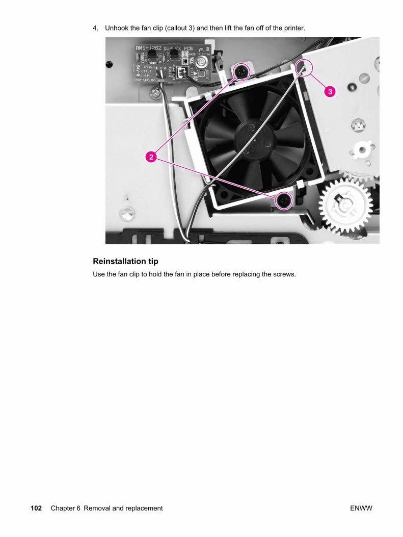
4. Unhook the fan clip (callout 3) and then lift the fan off of the printer.
Reinstallation tipUse the fan clip to hold the fan in place before replacing the screws.
102 Chapter 6 Removal and replacement ENWW
Duplex-drive gears/face-down gears
NOTE HP LaserJet 1320 Series printers contain duplex-drive gears. HP LaserJet 1160 printerscontain face-down gears.
1. Remove all covers (see Covers).
2. Remove the fan (see Fan).
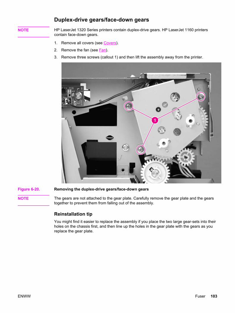
3. Remove three screws (callout 1) and then lift the assembly away from the printer.
Figure 6-20. Removing the duplex-drive gears/face-down gears
NOTE The gears are not attached to the gear plate. Carefully remove the gear plate and the gearstogether to prevent them from falling out of the assembly.
Reinstallation tipYou might find it easier to replace the assembly if you place the two large gear-sets into theirholes on the chassis first, and then line up the holes in the gear plate with the gears as youreplace the gear plate.
ENWW Fuser 103
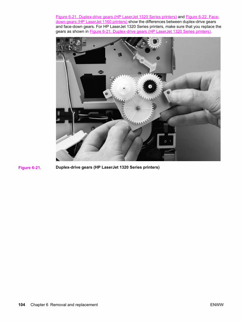
Figure 6-21. Duplex-drive gears (HP LaserJet 1320 Series printers) and Figure 6-22. Face-down gears (HP LaserJet 1160 printers) show the differences between duplex-drive gearsand face-down gears. For HP LaserJet 1320 Series printers, make sure that you replace thegears as shown in Figure 6-21. Duplex-drive gears (HP LaserJet 1320 Series printers).
Figure 6-21. Duplex-drive gears (HP LaserJet 1320 Series printers)
104 Chapter 6 Removal and replacement ENWW
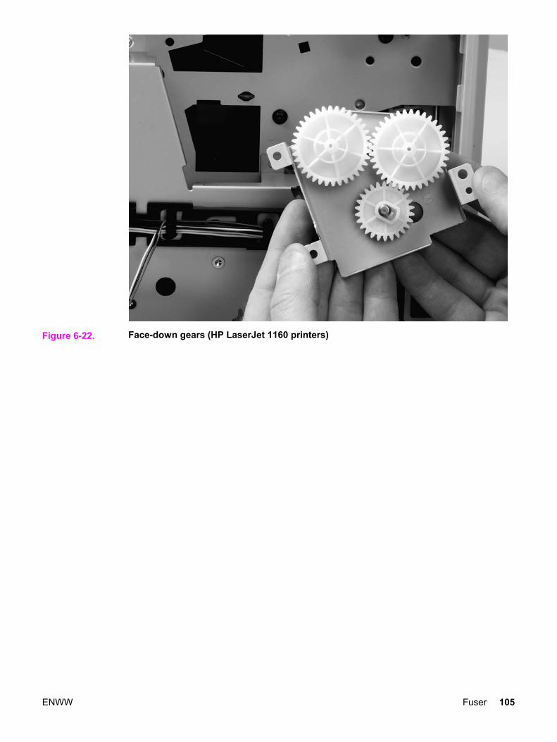
Figure 6-22. Face-down gears (HP LaserJet 1160 printers)
ENWW Fuser 105
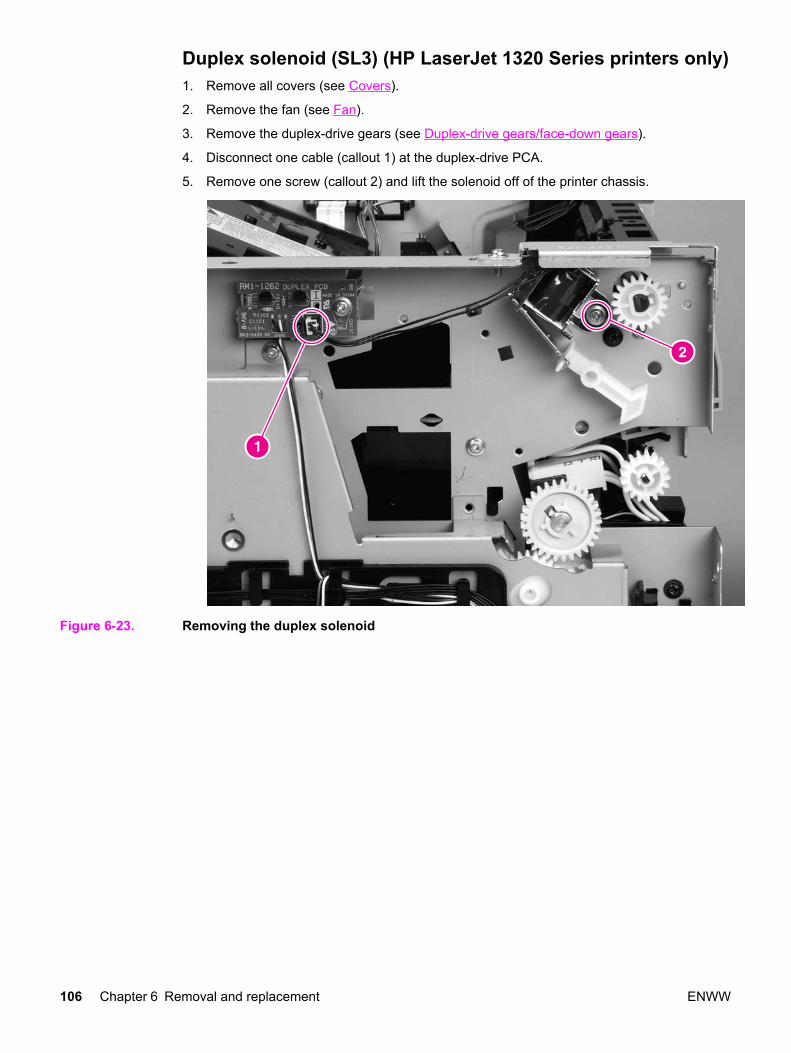
Duplex solenoid (SL3) (HP LaserJet 1320 Series printers only)1. Remove all covers (see Covers).
2. Remove the fan (see Fan).
3. Remove the duplex-drive gears (see Duplex-drive gears/face-down gears).
4. Disconnect one cable (callout 1) at the duplex-drive PCA.
5. Remove one screw (callout 2) and lift the solenoid off of the printer chassis.
Figure 6-23. Removing the duplex solenoid
106 Chapter 6 Removal and replacement ENWW
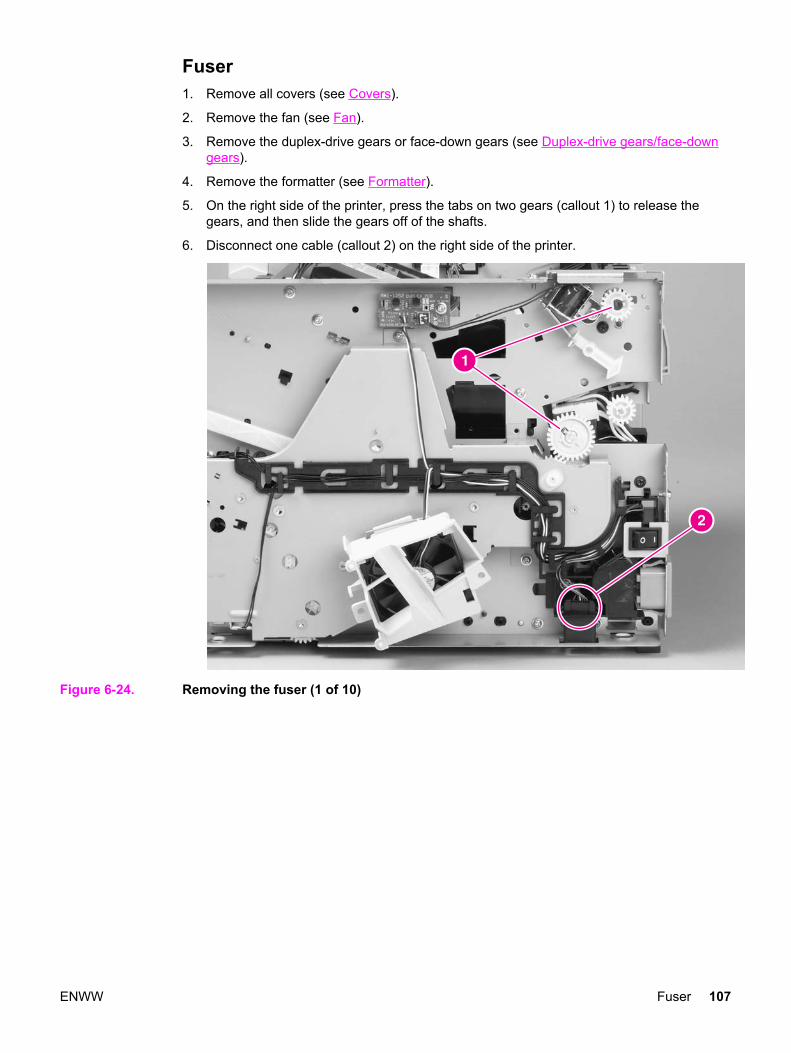
Fuser1. Remove all covers (see Covers).
2. Remove the fan (see Fan).
3. Remove the duplex-drive gears or face-down gears (see Duplex-drive gears/face-downgears).
4. Remove the formatter (see Formatter).
5. On the right side of the printer, press the tabs on two gears (callout 1) to release thegears, and then slide the gears off of the shafts.
6. Disconnect one cable (callout 2) on the right side of the printer.
Figure 6-24. Removing the fuser (1 of 10)
ENWW Fuser 107
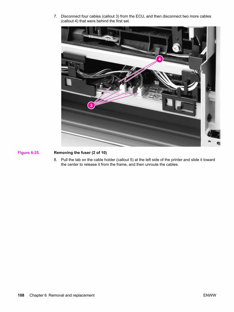
7. Disconnect four cables (callout 3) from the ECU, and then disconnect two more cables(callout 4) that were behind the first set.
Figure 6-25. Removing the fuser (2 of 10)
8. Pull the tab on the cable holder (callout 5) at the left side of the printer and slide it towardthe center to release it from the frame, and then unroute the cables.
108 Chapter 6 Removal and replacement ENWW
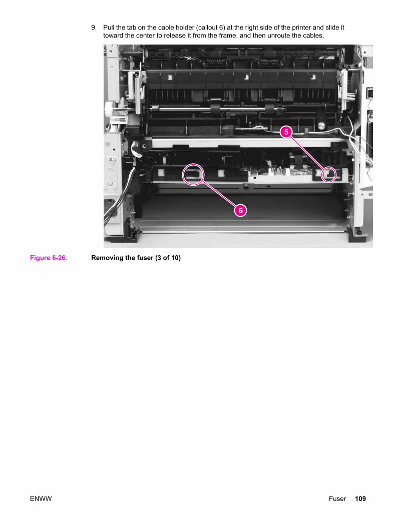
9. Pull the tab on the cable holder (callout 6) at the right side of the printer and slide ittoward the center to release it from the frame, and then unroute the cables.
Figure 6-26. Removing the fuser (3 of 10)
ENWW Fuser 109
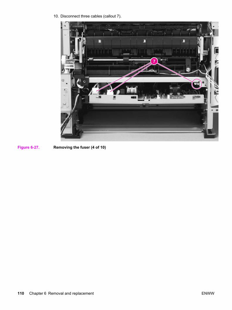
10. Disconnect three cables (callout 7).
Figure 6-27. Removing the fuser (4 of 10)
110 Chapter 6 Removal and replacement ENWW
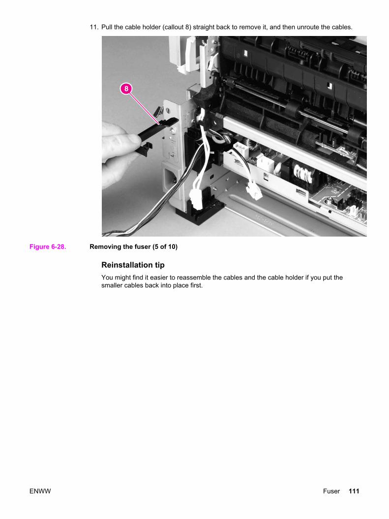
11. Pull the cable holder (callout 8) straight back to remove it, and then unroute the cables.
Figure 6-28. Removing the fuser (5 of 10)
Reinstallation tipYou might find it easier to reassemble the cables and the cable holder if you put thesmaller cables back into place first.
ENWW Fuser 111
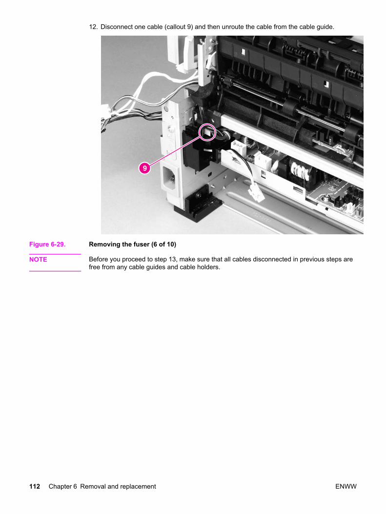
12. Disconnect one cable (callout 9) and then unroute the cable from the cable guide.
Figure 6-29. Removing the fuser (6 of 10)
NOTE Before you proceed to step 13, make sure that all cables disconnected in previous steps arefree from any cable guides and cable holders.
112 Chapter 6 Removal and replacement ENWW
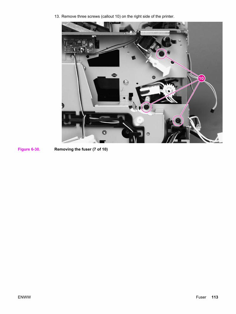
13. Remove three screws (callout 10) on the right side of the printer.
Figure 6-30. Removing the fuser (7 of 10)
ENWW Fuser 113
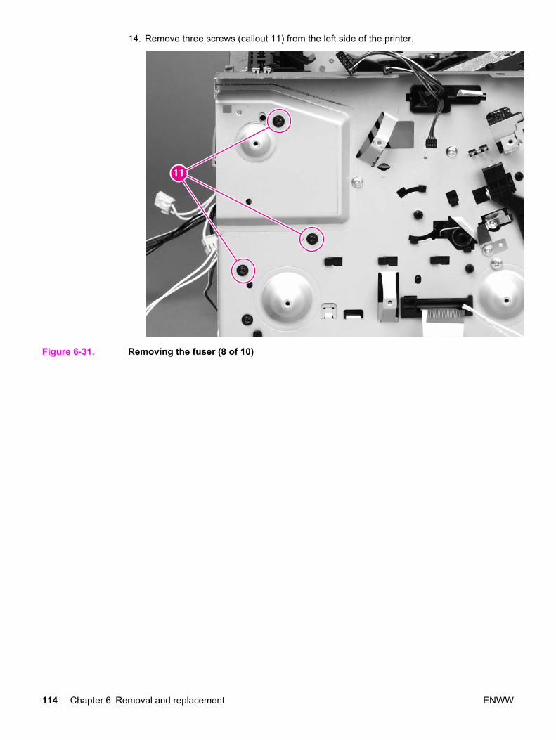
14. Remove three screws (callout 11) from the left side of the printer.
Figure 6-31. Removing the fuser (8 of 10)
114 Chapter 6 Removal and replacement ENWW
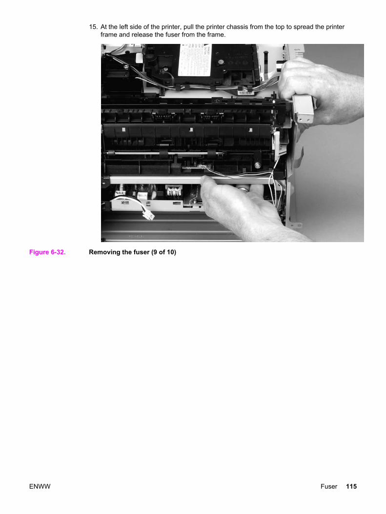
15. At the left side of the printer, pull the printer chassis from the top to spread the printerframe and release the fuser from the frame.
Figure 6-32. Removing the fuser (9 of 10)
ENWW Fuser 115
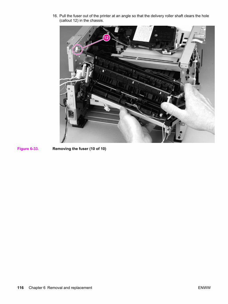
16. Pull the fuser out of the printer at an angle so that the delivery roller shaft clears the hole(callout 12) in the chassis.
Figure 6-33. Removing the fuser (10 of 10)
116 Chapter 6 Removal and replacement ENWW
Pickup and feed assemblies
This section covers the major assemblies of the pickup and feed system: the transfer rollerand the registration assembly.
For information about replacing the pickup roller, see Changing the pickup roller.
For information about replacing the separation pad, see Changing the printer separation pad.
Transfer roller
NOTE It is important to make sure that the transfer roller needs to be replaced before removing it.Excess handling can cause additional damage.
1. Open the print-cartridge door and remove the print cartridge, see Replacing the printcartridge.
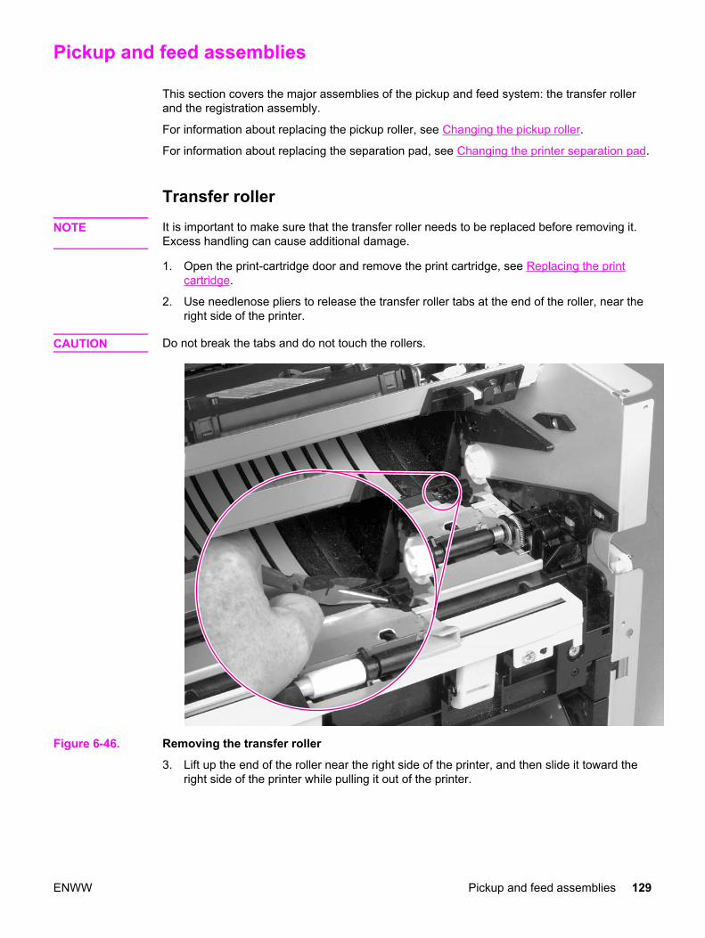
2. Use needlenose pliers to release the transfer roller tabs at the end of the roller, near theright side of the printer.
CAUTION Do not break the tabs and do not touch the rollers.
Figure 6-46. Removing the transfer roller
3. Lift up the end of the roller near the right side of the printer, and then slide it toward theright side of the printer while pulling it out of the printer.
ENWW Pickup and feed assemblies 129
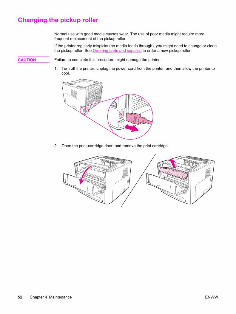
Changing the pickup roller
Normal use with good media causes wear. The use of poor media might require morefrequent replacement of the pickup roller.
If the printer regularly mispicks (no media feeds through), you might need to change or cleanthe pickup roller. See Ordering parts and supplies to order a new pickup roller.
CAUTION Failure to complete this procedure might damage the printer.
1. Turn off the printer, unplug the power cord from the printer, and then allow the printer tocool.
2. Open the print-cartridge door, and remove the print cartridge.
52 Chapter 4 Maintenance ENWW
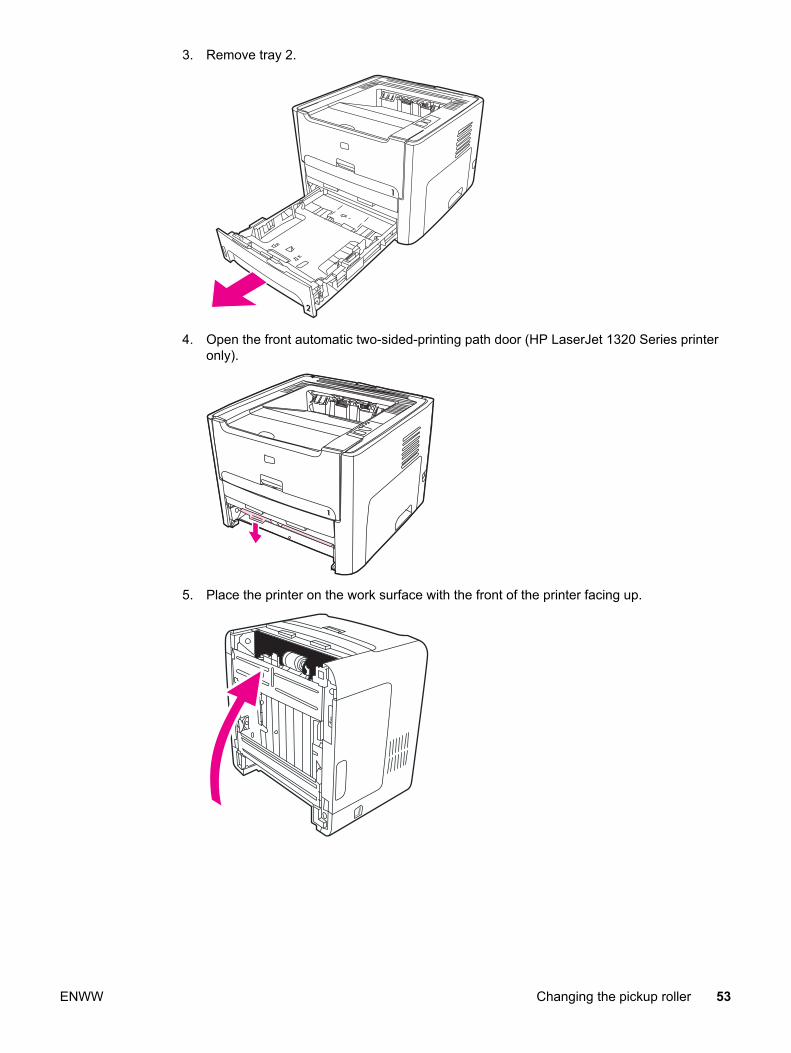
3. Remove tray 2.
4. Open the front automatic two-sided-printing path door (HP LaserJet 1320 Series printeronly).
5. Place the printer on the work surface with the front of the printer facing up.
ENWW Changing the pickup roller 53
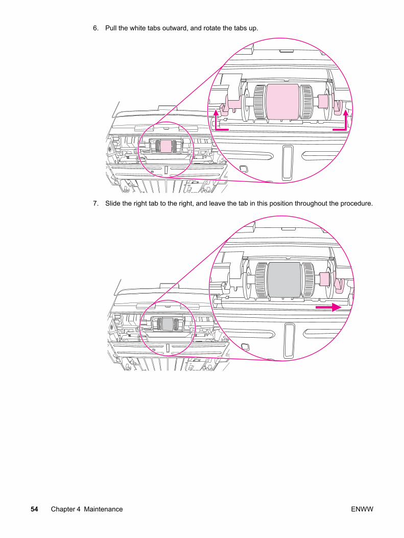
6. Pull the white tabs outward, and rotate the tabs up.
7. Slide the right tab to the right, and leave the tab in this position throughout the procedure.
54 Chapter 4 Maintenance ENWW
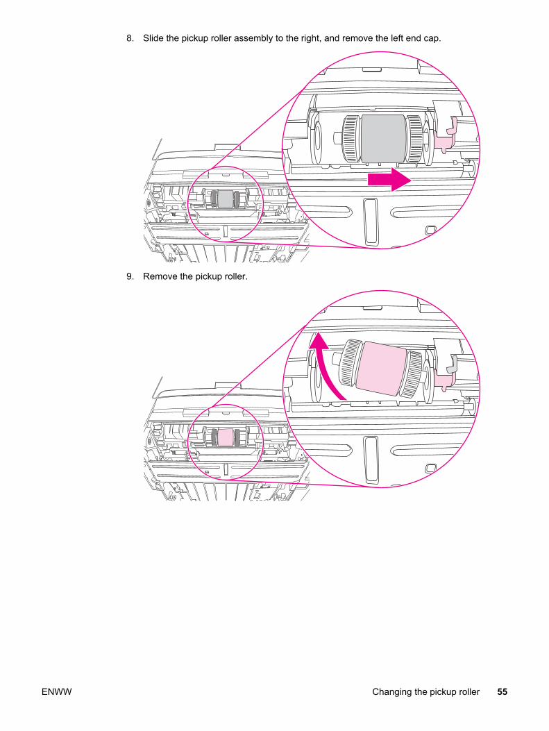
8. Slide the pickup roller assembly to the right, and remove the left end cap.
9. Remove the pickup roller.
ENWW Changing the pickup roller 55
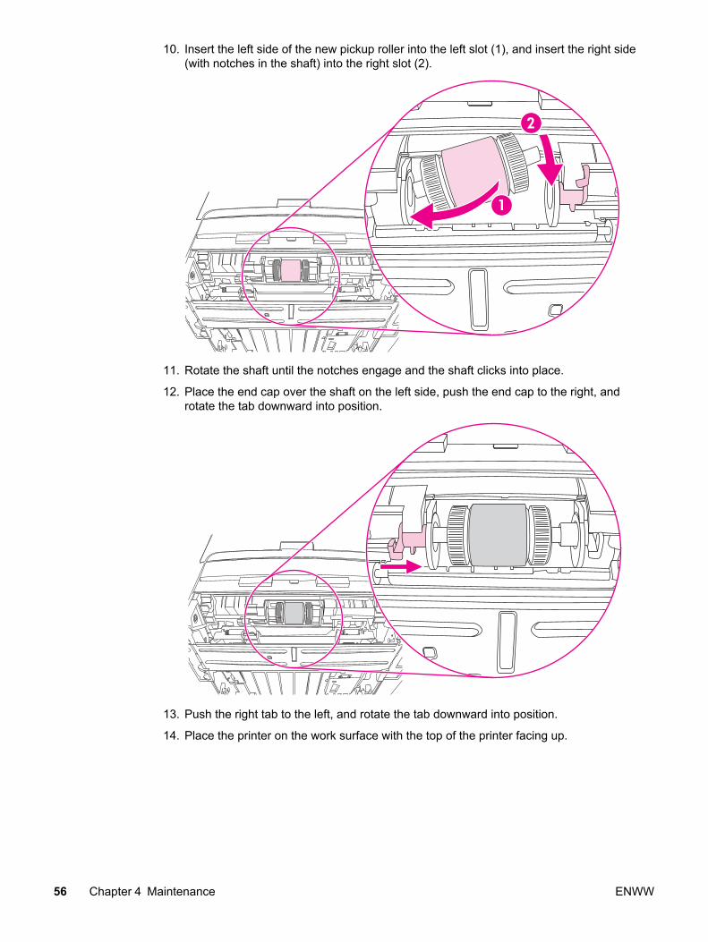
10. Insert the left side of the new pickup roller into the left slot (1), and insert the right side(with notches in the shaft) into the right slot (2).
11. Rotate the shaft until the notches engage and the shaft clicks into place.
12. Place the end cap over the shaft on the left side, push the end cap to the right, androtate the tab downward into position.
13. Push the right tab to the left, and rotate the tab downward into position.
14. Place the printer on the work surface with the top of the printer facing up.
56 Chapter 4 Maintenance ENWW
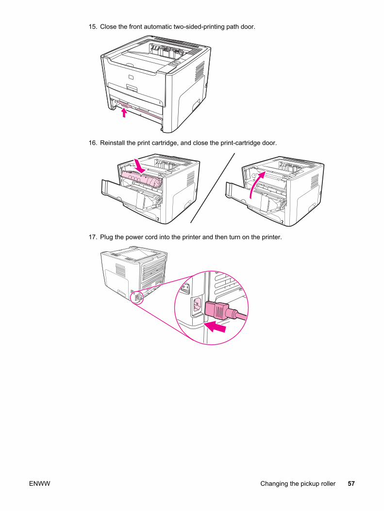
15. Close the front automatic two-sided-printing path door.
16. Reinstall the print cartridge, and close the print-cartridge door.
17. Plug the power cord into the printer and then turn on the printer.
ENWW Changing the pickup roller 57
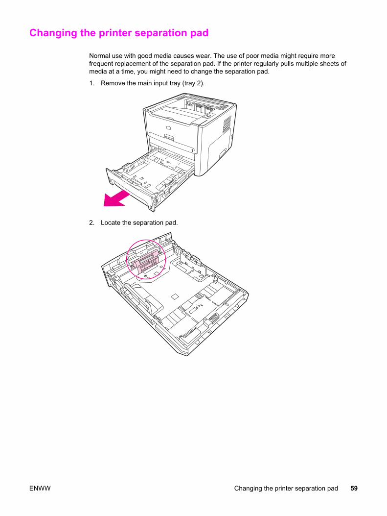
Changing the printer separation pad
Normal use with good media causes wear. The use of poor media might require morefrequent replacement of the separation pad. If the printer regularly pulls multiple sheets ofmedia at a time, you might need to change the separation pad.
1. Remove the main input tray (tray 2).
2. Locate the separation pad.
ENWW Changing the printer separation pad 59

3. Remove the screws.
60 Chapter 4 Maintenance ENWW
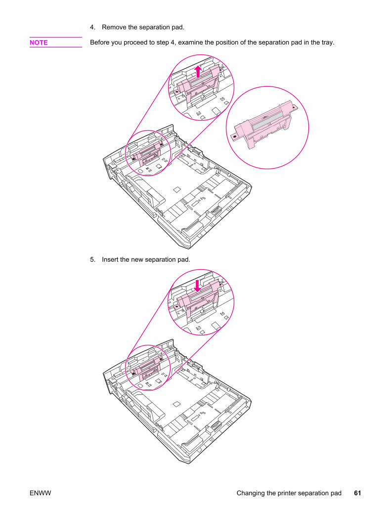
4. Remove the separation pad.
NOTE Before you proceed to step 4, examine the position of the separation pad in the tray.
5. Insert the new separation pad.
ENWW Changing the printer separation pad 61
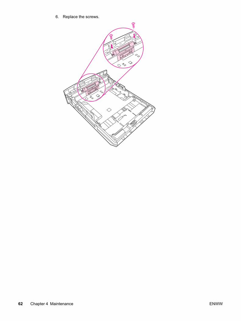
6. Replace the screws.
62 Chapter 4 Maintenance ENWW


![HP LaserJet 1100h10032.2 TC RSTU/VWXY˙%& Z[ HP LaserJet 1100 2 34\] HP LaserJet 1100 ^2_](https://static.fdocuments.net/doc/165x107/60e4caee120602597e1c9852/hp-laserjet-2-tc-rstuvwxy-z-hp-laserjet-1100-2-34-hp-laserjet-1100-2.jpg)