How to solder - UZHppyk/BasicsOfInstrumentation/Soldering... · How to solder This pdf refers on...
29
1 How to solder This pdf refers on informations from the site: http://store.curiousinventor.com/guides/ Have also a look to the 7min. Tutorial video on: http://store.curiousinventor.com/guides/How_to_Solder Select a Soldering Iron A 25 or 30 Watt iron should suffice for most small electronics work. 1. Most soldering "guns" are vastly overpowered for electronics soldering and can easily overheat components or expose them to harmful voltages. However, some people cleverly use them to solder multiple leads on surface mount devices. Soldering "guns" are for plumbing and much heavier duty applications, and are usually over 100 Watts. The "guns" work by passing high currents through the tips, and these currents can generate voltages that damage electronic components. Also, magnetic fields from guns with transformers can damage some electronics.By forming the heating element in the shape of of the chip, a soldering gun can be used to heat many leads simultaneously. 2. How much wattage do you need for a particular application and how does wattage relate to tip temperature? A loose analogy: Imagine a car tire has a leak, but you’re trying to keep it inflated by pumping air into the tire at the same time it's escaping out the leak. The bigger the leak, the more air you have to pump into it to keep the pressure up. If the tire pressure represents tip temperature and the air lost through the leak represents heat lost through the tip, then wattage represents the maximum amount of air your pump could supply. Once more air escapes through the leak than your pump can replace, the tire pressure (or tip temperature) starts to drop. If you had a very small leak and a huge pump (say a 100 Watt iron equivalent), you might be afraid that the pump would cause the tire to explode since so much more air is going in and so little going out. But if you have a nozzle to regulate the pump's air, you could only allow just the right amount of air in to replace what's lost through the leak. This is how "temperature controlled" soldering irons work. As long as you aren't losing more heat out of the tip than the iron can replace (up to its rated wattage), it will automatically regulate just the right amount of heat into the tip to maintain the same temperature. However, typical plug-in irons have no such regulation. A 15 Watt iron always delivers 15 Watts of heat to the tip, and the tip temperature stops increasing only when 15 Watts of heat escape through the air. When the tip touches a part, its temperature drops, and if the part you're soldering can dissipate enough heat, the temperature will keep dropping until it won't melt solder any more. After the iron is pulled away from the joint, the temperature will climb again. There is some amount of natural regulation: as the tip gets hotter, it dissipates more heat, and as it gets cooler, it dissipates less. Usually, the bigger the component the more heat it can absorb and dissipate, so the general rule is that you need more wattage for larger parts. If you're just soldering small resistors and ICs, 15 Watts will probably suffice, but you may have to wait a bit in between joints for the tip to recover. If you're soldering larger components, especially ones with heat sinks (like voltage regulators), or doing a lot of soldering, you'll probably want a 25 or 30 Watt iron. For soldering larger things like 10 gauge copper wire, motor casings, or large heat sinks, you may need upwards of a 50 Watt iron or more. The following video shows what happens to tip temperature as 15, 25, and 40 Watt irons solder various sizes of wires and components. For cheap irons, higher wattage does indeed mean higher temperatures! What is the difference between cheap RadioShack® irons and more expensive ones like Wellers®? What do $100+ and $400+ soldering "stations" have over the cheaper kinds that plug straight into the wall? expand Among the irons that plug straight into a wall and don't have a separate station, the dirt cheap kinds will work satisfactorily for many applications. From personal experience, the tips on RadioShack® irons often come loose and sometimes can be impossible to remove. The irons can also get uncomfortably hot to hold after several hours of use. The more professional Weller (or other) lines are made for longer, continuous use and have insulation on the handles that keeps them cooler. They
Transcript of How to solder - UZHppyk/BasicsOfInstrumentation/Soldering... · How to solder This pdf refers on...

1
How to solder This pdf refers on informations from the site: http://store.curiousinventor.com/guides/ Have also a look to the 7min. Tutorial video on: http://store.curiousinventor.com/guides/How_to_Solder
Select a Soldering Iron A 25 or 30 Watt iron should suffice for most small electronics work.
1. Most soldering "guns" are vastly overpowered for electronics soldering and can easily overheat components or expose them to harmful voltages. However, some people cleverly use them to solder multiple leads on surface mount devices. Soldering "guns" are for plumbing and much heavier duty applications, and are usually over 100 Watts. The "guns" work by passing high currents through the tips, and these currents can generate voltages that damage electronic components. Also, magnetic fields from guns with transformers can damage some electronics.By forming the heating element in the shape of of the chip, a soldering gun can be used to heat many leads simultaneously.
2. How much wattage do you need for a particular application and how does wattage relate to tip temperature?
A loose analogy: Imagine a car tire has a leak, but you’re trying to keep it inflated by pumping air into the tire at the same time it's escaping out the leak. The bigger the leak, the more air you have to pump into it to keep the pressure up. If the tire pressure represents tip temperature and the air lost through the leak represents heat lost through the tip, then wattage represents the maximum amount of air your pump could supply. Once more air escapes through the leak than your pump can replace, the tire pressure (or tip temperature) starts to drop. If you had a very small leak and a huge pump (say a 100 Watt iron equivalent), you might be afraid that the pump would cause the tire to explode since so much more air is going in and so little going out. But if you have a nozzle to regulate the pump's air, you could only allow just the right amount of air in to replace what's lost through the leak. This is how "temperature controlled" soldering irons work. As long as you aren't losing more heat out of the tip than the iron can replace (up to its rated wattage), it will automatically regulate just the right amount of heat into the tip to maintain the same temperature. However, typical plug-in irons have no such regulation. A 15 Watt iron always delivers 15 Watts of heat to the tip, and the tip temperature stops increasing only when 15 Watts of heat escape through the air. When the tip touches a part, its temperature drops, and if the part you're soldering can dissipate enough heat, the temperature will keep dropping until it won't melt solder any more. After the iron is pulled away from the joint, the temperature will climb again. There is some amount of natural regulation: as the tip gets hotter, it dissipates more heat, and as it gets cooler, it dissipates less.� Usually, the bigger the component the more heat it can absorb and dissipate, so the general rule is that you need more wattage for larger parts. If you're just soldering small resistors and ICs, 15 Watts will probably suffice, but you may have to wait a bit in between joints for the tip to recover. If you're soldering larger components, especially ones with heat sinks (like voltage regulators), or doing a lot of soldering, you'll probably want a 25 or 30 Watt iron. For soldering larger things like 10 gauge copper wire, motor casings, or large heat sinks, you may need upwards of a 50 Watt iron or more. The following video shows what happens to tip temperature as 15, 25, and 40 Watt irons solder various sizes of wires and components. For cheap irons, higher wattage does indeed mean higher temperatures!
What is the difference between cheap RadioShack® irons and more expensive ones like Wellers®? What do $100+ and $400+ soldering "stations" have over the cheaper kinds that plug straight into the wall? expand Among the irons that plug straight into a wall and don't have a separate station, the dirt cheap kinds will work satisfactorily for many applications. From personal experience, the tips on RadioShack® irons often come loose and sometimes can be impossible to remove. The irons can also get uncomfortably hot to hold after several hours of use. The more professional Weller (or other) lines are made for longer, continuous use and have insulation on the handles that keeps them cooler. They

2
can also take a wider variety of tips. Soldering iron "stations" usually provide some control over the heat being supplied to the iron tip. Ones that are temperature controlled automatically control the amount of heat delivered to the tip so that it remains at a set temperature. In every iron, when the tip touches a component, some heat is lost and the temperature drops. One measure of quality is the time needed for the tip to regain its temperature. A nice feature of many soldering stations is that the tip heats up in seconds after you turn it on. Many stations also allow you to hot-swap the iron tip, which can be very helpful if you're alternating between surface mount joints and larger components.
If standard tin-lead solder melts below 400 °F (and lead free below 500 °F), why do most soldering irons have tip temperatures between 600 and 800 °F? Just what is the right soldering temperature? expand The basic reason that tips are so much hotter than solder's melting point is because that difference helps to transfer heat faster to the joint. What is the "correct" temperature is a debatable topic, but a common rule of thumb is to start off at 600 °F and increase from there until acceptable results are achieved. Typical Kester (a solder manufacturer) datasheets recommend 600-700 °F for lead-based solder, and 700-800 °F for lead-free solder. "No-clean" or "low solids" fluxes will burn off before a joint can be made with higher temperatures, so low temperatures (below 700) may be essential for these fluxes. From Kester's hand-soldering knowledge base: "When hand soldering with a rosin flux such as the Kester #44 or the # 285 the recommended iron tip temperature is 750°F. If you are soldering with a low residue no clean solder such as the #245or # 275 we recommend a tip temperature of 600-650°F. What are acceptable results? The goal is to heat up the parts enough so that solder will adhere to them and form a good bond. The higher the iron temperature, the faster it will heat up the parts, so why not set it extremely high to work faster? Besides the obvious increased risk of overheating components and the board, higher temperatures cause the iron tip to oxidize faster and can significantly reduce its life. Some claim a 10 °C rise reduces tip life by half (ref p.33). For occasional use, though, tip life may not be much of a factor, especially if the tip is kept covered with solder at all times.
Tip size and shape: a basic guide is to pick a tip that's slightly smaller than the pad you're soldering to. From there, you want a tip with a large thermal mass and short stroke (why?) In most soldering irons, the tip is not actually the heater, but sits in between your work and the heater. You can think of it like a heat bucket that empties into your work and gets filled again by the heater. Typically touching a component empties heat out of the tip much faster than the iron can replace it, and if you have a small bucket (tip), the temperature will quickly drop to an ineffective level. Especially if you have a small wattage iron (15 Watts or less), the temperature will drop before you can heat up a larger part, or you'll have to wait a bit in between joints for the tip temperature to recover. With a bigger bucket (tip), you can handle larger joints with smaller wattage, but eventually you'll need to step up the wattage. The "stroke", or length of the tip should be minimized to get the heater closer to the work; it takes some time for heat to transfer through the tip. This is balanced with the need to get into tight places where you need a longer tip.
What do common tip shapes look like and what applications are they best for?

3
Screwdriver, spade, and conical are some of the more common tip shapes. Personal preference is the biggest factor when choosing a tip, but the goal is to get as much surface area contact between the tip and work as possible. Chisel and spade tips have more surface area at their ends, and also "hold" solder at their tips more readily than conical tips, which have a tendency to draw solder away. Even for fine pitch surface mount soldering, having a small flat at the end can be helpful.
There are myriad other tip shapes and sizes. The picture to the right shows one Plato catalog page of many. Some other non-standard shapes include a knife-blade (useful for fine pitch leads) and a surface mount desoldering tip.
To preserve tip life, the number one thing you can do is reduce the tip temperature (if your iron allows this). After that, ALWAYS keep a layer of solder on the tip to prevent the tip itself from oxidizing, and clean it in between uses. Put a glob of solder whenever you put it back in the stand, and before you turn it off. When heating up a new tip for the first time, hold solder against it so the tip can be covered as soon as the iron gets hot enough. The longer flux residues and oxides are left on the tip, the harder they are to clean off. They also can drastically reduce the tip's ability to heat up a part, and prevent solder from "wetting" the tip. Regular cleaning of the tip before use is one of the best ways to prolong tip life and make soldering easier. It's important that solder "wet" or cling to the surface of the iron--without solder in between the tip and work the tip's ability to heat is drastically reduced.
What about gas powered irons and the Cold Heat® iron that is supposedly touchable 1 sec. after use? Butane (and other gas) powered irons are mainly used in situations where electrical power isn't

4
available. Weller sells some battery powered irons as well. Everyday Practical Electronics gives a pretty damning review of the Cold Heat iron here, in addition to having one of the better how-to guides out there. To summarize, the Cold Heat® iron has a forked end that you must bridge with the work or solder to turn on the iron, so it can be hard to hold it in a place that keeps it on and also effectively heats the part. Many people complain about pushing harder to make a good connection and then having the brittle tips break. Running power through your work to heat it may not be the greatest idea with some parts. Finally, the iron doesn't get hot enough for a lot of jobs, or cool enough to do anything like throwing it in your pocket right after use. But for something that's portable and cordless, heats up and down in under a few seconds, maybe it's worth the price ($20). Weller's battery powered ($20) iron doesn't have a forked end and supposedly heats up in under 15 seconds, but I don't know about cool-down time.

5
What kind of solder (rosin cored, etc. lead-free)? What is flux and when is it necessary?
As a starting place, for most small electronics soldering, 1/32 inch (.03) rosin-cored, 60/40 (tin-lead) or 63/37 solder should work fine. Rosin-cored lead-free is fine, too. Unless you have reason otherwise, don't use "no-clean" solder--it's very likely that you don't need to clean the regular rosin-cored solder. The solder should be thin enough to prevent accidentally applying too much (and causing a solder bridge), but thick enough so that more doesn't have to be gathered from the coil too often.
Besides affecting your feed-rate and convenience, the solder thickness also relates to the amount of flux that is delivered. Flux is basically a weak acid that removes oxides so that solder can adhere to the metal, and is so essential to the soldering process that it's built into the core of common wire-solder. It also helps the solder spread out (reduces surface tension), transfer heat, and acts as a protective blanket to keep oxygen away from the metal until solder displaces it.
For the most part, manufacturers include a sufficient amount of flux in the wire, but if you use an extremely thin wire there may not be enough to clean the joint OR the iron tip. Consider using a thicker gauge for cleaning the tip periodically if you're using especially thin solder. Liquid flux is helpful for SMD soldering, too.
When picking a wire-solder, there are 4 features to decide on: flux type and amount (% weight), alloy (tin-lead, lead free, silver bearing, etc.), thickness and total amount (1oz, 1lb?).
Flux: Just what is flux, what kinds are there, and when do I need liquid flux?
Why it's needed: Solder doesn't just freeze on a joint, it actually forms a metallurgical bond by dissolving and chemically reacting with the base material. Unfortunately, almost all metals oxidize in air and form an oxidized layer that prevents solder from wetting and bonding to them. What is oxidation?
Oxidation, is when Oxygen (or other oxidizing agents like sulfur) atoms combine with base materials, stripping loosely attached electrons and forming new compounds like iron(III) oxide. It is what happens when apple slices turn brown, iron rusts, copper turns black / green and unsolderable. (read references for more accurate/complete explanation)
Results vary significantly. When iron rusts, the oxides flake off until no iron is left. Alternatively, aluminum oxidizes extremely rapidly, but is then protected from additional oxidation by the oxide layer. This layer makes Al impossible to solder without using special solder and extremely aggressive flux, or plating the surface with a solderable metal, like nickel. The chromium in stainless steel fulfills the same function, oxidizing to form a protective barrier that is difficult to solder. Gold remains shiny

6
because it doesn't oxidize, and is easy to solder to, but forms brittle joints. Heat, moisture, and salt all increase the rate of oxidation.
Oxidation can add a hidden cost to components and boards that may have been sitting on the shelf for long periods of time, or have been exposed to hot, humid environments. Copper pads on PCBs (printed circuit boards) are covered with solder or are plated to prevent oxidation, but given enough time, oxygen can still penetrate these barriers. Surplus parts in particular may need a bit of steel wool.
Some interesting references: rusting chemical reaction fairly understandable explanation of oxidation wiki/Corrosion wiki/Oxidation
Oxidation occurs much faster at higher temperatures, so even if you somehow had clean metals to start with, you would still need flux to prevent new oxides from forming while soldering.
The main choice to make when deciding on a flux, whether it comes in a cored wire or a liquid or paste form, is how aggressive it should be. The more aggressive or "active" the flux, the harder the oxides it can remove, and the faster it can remove them. Going from weakest to strongest, typical choices for hand soldering applications include: "no clean", RMA (Rosin Mildly Activated), RA (Rosin Activated), and water soluble. A newer classification system (J-STD-004) has recently been adopted and classifies fluxes not by rosin content, but by activity, material, and halide presence.
The new system classifies flux by material (RO=rosin, RE=resin, OR=organic, IN=inorganic), activity level (Low, Moderate, High), and halide presence (0 or 1). No-clean, rosin-based no-clean fluxes might be labeled ROL0 or ROL1. Although there is no direct translation between the old system and new, most R and RMA fluxes fall under Low activity level, RA are generally labeled as Moderate activity, and water soluble are High activity. (source IPC-HDBK-001 www.ipc.org)
The downside to choosing a more aggressive flux is that the residues left over after soldering MAY be corrosive, conductive, or enable fern-like growths called "dendrites" to grow between connections. A brief description (p.29) of dendrite growth and some great pictures at the end of this paper.
Because of the risk of corrosion and dendrite growth, most manufacturers clean off the residue from RMA and RA fluxes, and some even clean "no-clean" residues. The question of what flux to use and whether / how to clean it is quite involved.
Rosin flux is quite an interesting animal. Made from pine tree sap, at room temperature, it's an excellent insulator and non-corrosive. When it hits 226 °F it begins to turn acidic and attack oxides, but then when it cools it supposedly leaves residues that are again inert. Kester's data sheet for "44" flux (classified as RA and ROM1) claims no cleaning whatsoever is necessary. I haven't read of any manufacturers that would use a RA (or even an RMA) flux and not clean it--the military won't even use a RA flux WITH cleaning because of the risk that some will be left behind. This Chemtronics author recommends cleaning even the "no-clean" fluxes. He also points out that even if the residue is non-corrosive and non-conductive, it might be tacky and attract dust that causes a short.
To add one more piece to the puzzle, flux generally gets used up during the soldering process. This is why no-clean fluxes are oftentimes ineffectual for lead-free soldering, which can require slightly higher temperatures and longer heating because the lead-free solder "wets" slower. The no-clean flux can burn off before the joint is complete. Alternatively, if you apply liquid flux far from a joint, it may still be active (corrosive) if it never got heated.

7
I'm not making missile guidance electronics, I'm making a robot that pours a beer, what flux should I use and do I really need to clean? Even manufacturers of non-life critical electronics have much more stringent reliability requirements than an individual. They must ensure that tens of thousands of products will work for multiple years, not a single project.
The safe advice is to use the least aggressive flux that enables solder to quickly wet or cling to the surfaces, and then clean off the residues with alcohol and lint-free wipes (don't just spread the flux around). Try starting with a rosin-based mildly activated flux: RMA. I am inclined to trust Kester's spec sheet for "44" (RA) flux that says it does not actually require cleaning. Other flux manufacturers may have RA or RMA level fluxes that do indeed need to be cleaned, so if you don't know what you're using, cleaning is probably prudent. If you are going to clean rosin fluxes, do it soon after soldering because they quickly harden (see pics under 'Cleaning'). Finally, I would personally avoid no-clean fluxes and solder unless you have a critical application and very clean parts.
Lead-free solder generally requires a made-for-lead-free flux designed to be used under slightly higher temperatures.
Liquid flux can greatly help with surface mount soldering and desoldering components, but the flux inside cored-solder should be sufficient for through hole components. When soldering SMD components and desoldering pretty much anything, liquid flux acts as a blanket that helps to spread heat and also keep oxygen away from the metals. Finally, flux lowers the surface tension of solder, helping it to spread out and wick into connections.
A water-soluble flux may be necessary for heavily oxidized parts or difficult metals like nickel. Without question, clean these fluxes. Special fluxes and solders exist for aluminum and stainless steel and these also certainly require cleaning. Never use acid-core solder; it deposits zinc chloride into the solder that cannot be cleaned out. A final reason to clean flux residues is if you'd like to apply a conformal coating and aren't sure whether it will adhere to those residues.
Some more references:
o Never use acid-core and how to solder to stainless steel (Kester) o White residue and all about rosin (more Kester) o Good mini-class on fluxes: Bolton University o To clean or not to clean and a brief history of electronics cleaning: more Bolton o The Kester catalog provides good info on the solderability and flux requirements of various
materials (see p.14). o Flux residues and what to do about them. This explains a bit about cleaning options and the
health risks of rosin and non-rosin fluxes.
Alloy: 60/40, 63/37, tin-lead, lead-free, silver bearing, RoHS, eutectic, oh my...

8
o Standard lead-based solder is made of tin and lead. When you see 60/40 or 63/37, it means 60% tin by weight, 40% lead. Either once of these alloys should be fine for typical small electronics soldering. 63/37 in bulk is slightly more expensive because of additional tin, but has the special property of being a "eutectic" alloy, which transitions from liquid to solid at one temperature (like water) instead of range of temperatures. Basically, in non-eutectic alloys like 60/40, there is a "pasty" region of temperature where portions of the solder are frozen and other portions are liquid. What does this mean for soldering and is 63/37 really that much better?
Alloy metals have some interesting properties that are different from the metals comprising them. In tin-lead solder, the mixture has a lower melting point than either lead or tin alone, and the melting point varies depending on the portions. The mixture that yields the lowest melting point is called eutectic. This is also the only mix where all the constituents melt and freeze at the same temperature.
If the tin-lead alloy isn't eutectic (ie, if it is not 63% tin), it will go through a "pasty" phase while it freezes. Unlike water, which freezes entirely at 0 °C, some parts of a non-eutectic mixture of tin-lead freeze at higher temperatures than other parts. For a somewhat simplified explanation, if you held the temperature of 60/40 slightly above 361 °F, the "extra lead" would solidify and be floating in a liquid 63/37 eutectic mix. For a more exact and great explanation of this process, look here.
How is it that the mixture of two elements somehow lowers the melting point? And I quote: "increased entropy." Chew on this. (Another great phase-diagram explanation with a bonus of why ice and salt can get almost 30 °F below freezing--enough to freeze ice cream) And one last great explanation--talks a bit about grain structure and how solder isn't a simple homogeneous mixture of tin and lead.
This compares the difference between eutectic freezing in tin-lead and eutectic freezing in more complex 3 element lead-free alloys.

9
So which is better, 60/40 or 63/37? A decade or so back (before the lead-free movement), most manufacturers incurred about a 5% increase in cost to switch from 60/40 to 63/37. 63/37 flows slightly easier, makes shinier joints, and has a faster total freezing time which means there is less risk the joints will be "distrubed," which is what happens when the joint moves during solidification. This can lead to internal fractures that cause poor electrical connections and unreliable mechanical joints. Note that 63/37 doesn't freeze instantly (just like water)--it still has a window of time during which the joint can be disturbed, too.
I think most would say that the enhanced properties of 63/37 really only matter for mass soldering operations like wave or reflow soldering, and that there is little difference for hand soldering. A dull joint is more often caused by insufficient heat, dirt or oxides, or lack of flux rather than alloy makeup. (A no-clean flux may burn off before the joint is complete) Holding everything else constant, the difference in shininess between 60/40 and 63/37 is completely cosmetic. If you'd like to see a shiny 60/40 joint, try using Kester 60/40 with #44 flux.
o Silver bearing solder: (that is, contains silver, not for roller bearings) Silver is used in one of the leading alloys for lead free solder (An96.5% Ag3.0% Cu.5%) and also as an addition to tin-lead solder, usually in the 2-4% range (when you se 62/36/2 this means Sn64Pb36Ag2).
People claim that it flows better, has a lower melting point, is stronger, and has a higher conductivity. According to Indium's solder wire data sheet, their 2% silver solder has an electrical conductivity that is 11.9% of Cu compared to 11.5% of 63/37 tin-lead solder, a shear strength of 7540psi vs. 6200psi, and a tensile strength of 7000psi vs. 7500psi for 63/37. So, yes, the claims are true, and also mostly insignificant. Silver was initially added to solder to prevent silver platings on component leads from dissolving into the solder ("silver migration") and forming brittle joints. Having silver in the solder reduces migration, so you may want to use it on silver joints. (Note: this logic doesn't entirely make sense to me. If silver getting in the solder caused embrittlement, how does adding more silver prevent this?)
Audiophiles seem to be enamored by 4% silver bearing solder, namely some from WBT, Cardas, and WonderSolder. Are these really better for audio?
The superior claims include things like higher purity, eutectic alloys, higher conductivity, and better flux. I haven't found any controlled studies showing that a group of people can actually hear the difference, so I'm skeptical. Although additional silver does increase conductivity, the increase is small and the joint distance over which that conductivity applies is also extremely small. For what it's worth, here's a forum discussion that discusses a bit about solder in high-end audio and also a FAQ (scroll down)concerning solder on Cardas Audio's site. Another decent discussion.
Bad joints made with any solder can create a high-resistance connection, especially if the underlying components were heavily oxidized initially. My advice: if it makes you feel better, get it, but be wary of sellers that don't provide spec sheets.
o Lead-free Solder: As of July 1st, 2006, European laws mandated that new electronics be almost entirely lead free. As of yet, there are no US laws (outside CA) mandating the removal of lead, but most manufacturers are switching over for competitive reasons. More on RoHS, WEEE, and lead risks:
The European Union passed directives in 2003 stating that no equipment sold in Europe should, by July 2006, have more than .1% lead in any homogenous component (like a solder joint). The directives are known as the WEEE (Waste Electrical and Electronic Equipment) and RoHS (Restriction of Hazardous Substances) (wiki). There are corresponding laws in China, Korea, and California. Japan manufacturers actually voluntarily begin switching to lead

10
free years before RoHS or WEEE for competitive reasons. IPC's informative lead-free website: here.
Although only .5% of lead used in the US gets embedded in electronics (verses 80% in batteries), there is concern that the lead from those electronics will leach into ground water supplies from landfills. Why the concern over solder joints when batteries contain so much more lead? For the most part, lead containing batteries are recycled and regulated, whereas electronics are routinely just thrown away. The EPA claims that 1% of municipal waste is electronics. Interestingly, according to this publication by IPC, no studies have found any evidence of lead getting into the ground water from landfills.
Lead health risks: Lead does not get absorbed through the skin, and is actually not present in solder fumes to any appreciable degree (fumes are still bad for you, see fumes section below). The greatest risk of hand soldering with lead comes from ingesting lead by eating or smoking without first washing. Health risks include increased blood pressure, fertility problems, nerve disorders, muscle and joint pain, irritability, and memory or concentration problems. The latest health data indicates that there is no amount of lead that will not be detrimental to health. Google lead or start with this link.
Some great lead-free joint pictures: here.
The most popular lead-free alloy seems to be Tin 96.5% Silver 3.0% Copper .5%. The wiki page on solder mentions several different lead-free varieties. -AIM lead-free solders. -Huge list of Indium lead-free solders and their properties.
Lead-free solder generally melts at a higher temperature, and doesn't wet as quickly to metals. (Eutectic tin-lead solder melts at 361 °F and the SnAg3Cu.5 melts at 423 °F.) Manufacturers generally recommend setting soldering iron temperatures between 700-800 °F for lead-free instead of 600-700 °F for tin-lead soldering. The 15 Watt RadioShack® iron I had operated a bit below 500 °F, so soldering should be possible with it, but maybe slow. Technique wise, since lead-free wets slower, joints will take longer (upwards of 4-7 seconds), but this doesn't mean the soldering iron temperature should be turned up excessively--patience is better than higher temperatures. If you're going to use a lead-free solder, get a flux that's designed for the higher temperatures--the regular no-clean fluxes will likely burn off before doing their job.
A quick word on reliability. Some say that lead-free joints are stronger, and while the material is indeed stronger, it's less flexible than lead-based solder, so expansion and contraction due to temperature change has been shown to break components held by lead-free solder. It seems true mechanical reliability of lead-free vs. lead depends heavily on the situation (see p.30). There is also concern of something called "tin whiskers." These are extremely thin crystalline growths that grow perpendicularly out from surfaces. These took down some space systems and NASA has a great page here. These are different from dendrites (which grow on the surface) and appear to be more likely on bright all-tin platings. Most component platings used to consist of a tin-lead mixture, and since all-tin platings are a common lead-free replacement, people are concerned. I have yet to find any literature that points to TinSilverCopper solder as a risk factor, though. I believe it is a plating issue, only.
One more link: -Why tin or silver?
Thickness and Amount: As a general guide, .032" thick solder (21 gauge) should be suitable for through hole soldering and some surface mount soldering. For finer pitch surface mount devices, use .02" or .015", and if you're soldering a lot of switch terminals, or tinning thick gauge wire you may want .05". If you use .015" solder consider having some thicker solder on hand to re-tin your tip, since the amount of flux in .015" may not be enough to remove tip oxides. The picture below shows how the various thicknesses compare next to the standard .1" spaced DIP pins.
11
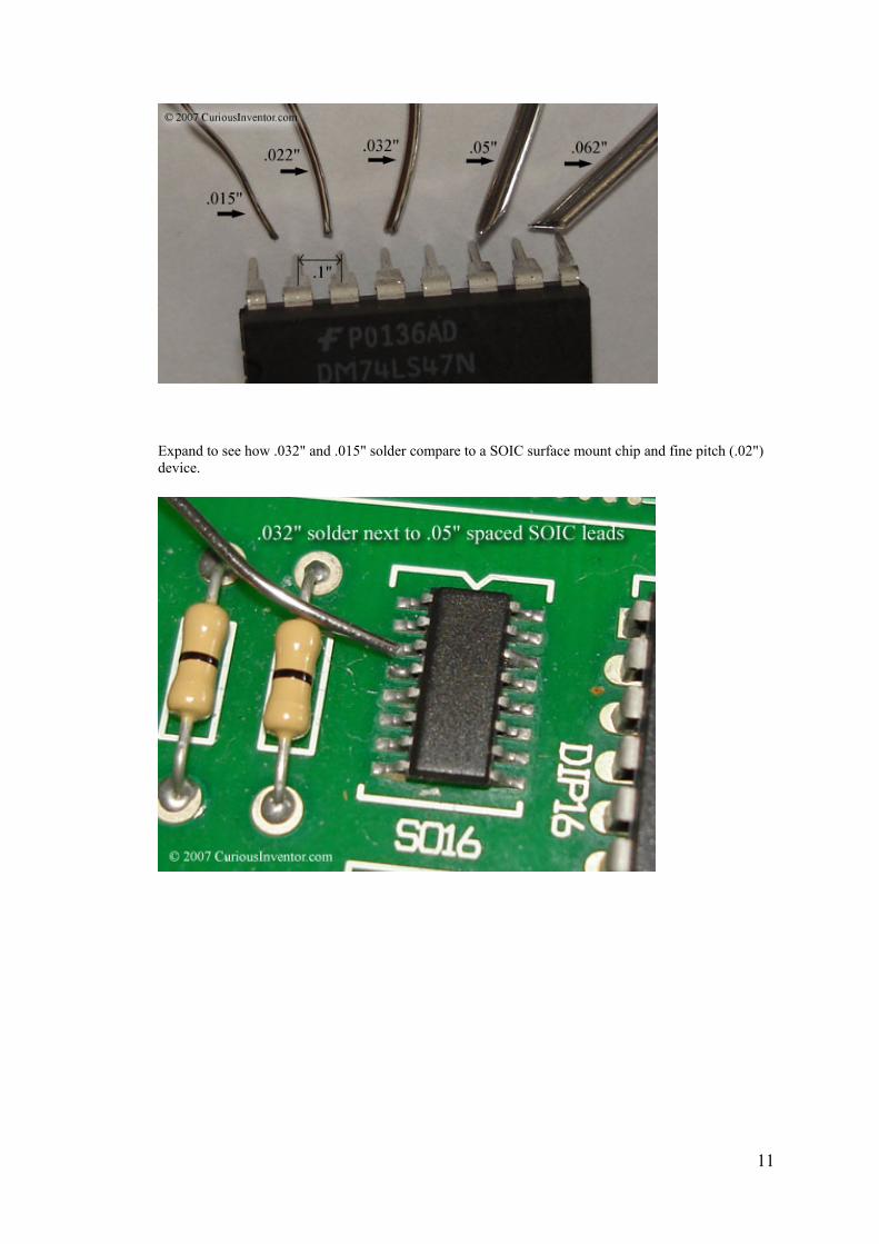
Expand to see how .032" and .015" solder compare to a SOIC surface mount chip and fine pitch (.02") device.

12
How much solder do I really need? An ounce? A pound? How long will a pound last?
To get a very approximate feel for just how much solder is in an ounce vs. a pound, I measured how much .032" solder it took to attach ten 16 pin DIPs. Trying to provide an upper bound, the soldering is excessive, and a generous glob was placed on the tip in between each chip to account for solder used to tin and protect the tip during normal use.
The ten chips took about 15" of generously applied .032" solder that weighed in approximately at .052oz. This particular solder weighed about .00348oz/in. At about 3.27e-4 oz/joint, a 1 oz spool should last 3060 joints, a half pound should last 25 thousand joints, and a pound should last about 50 thousand joints. Mileage will certainly vary with different sized solders, joints, tinning wires, and highway vs. city driving, but if you're not in a production environment, a half pound should last a while.

13
Solder Fumes:
What is exactly in solder fumes? Am I safer using lead-free solder?
Lead boils at over 3000 °F, and in most cases soldering tips should be kept below 750 °F, so it is highly unlikely that gaseous lead is present in the fumes. The fumes are actually from the flux boiling, which still isn't great for you--many of the chemicals found in cigarette smoke are found in flux fumes: formaldehyde, toluene, alcohols, and hydrochloric acid to name a few. Most of the public health literature indicates that asthma is the major health risk from soldering fumes (not cancer or lead poisoning). When acquired, it is permanent and can cause hyper sensitivity so that even small amounts of fumes bring on attacks. Surprisingly, scientists have not been able to determine what exactly in the fumes cause the health defects, nor what amounts are harmful. Yet, the British health department has set exposure limits of .05 mg/m^3 over 8 hours and .15 mg/m^3 over 15 minutes. I believe these limits have been shown to provide a safe work environment and also one for which the necessary systems / filters are financially reasonable.
Some informative links:
o Solder Fumes and You A British health department pamphlet explaining the health hazards of rosin-based flux fumes (irritation, headaches, dermatitis, asthma) and what precautions employees and employers should take. Note the total lack of any mentioning of lead poisoning.
o Workplace Exposure to Rosin-based Solder Flux Fume During Hand Soldering A study done by the UK Health and Safety Laboratory measuring exposure levels and also the effectiveness of various exhaust, ventilation, and filter systems.
o Measurement of the Performance of Air Cleaners Against the Particulate Element of Rosin-based Solder Flux Fume Another UK Health study investigating the effectiveness of various fume extraction and filter systems. Most interesting finding: although activated carbon filters can remove gaseous hazards, they are largely ineffective for fine particulate in the fumes which they believe to cause much of the harm. Some combination of carbon and HEPA filter is needed, and even these are useless without sufficient air flow.
Returning to the topic of lead, it is widely agreed that eating, smoking and drinking without first washing is the greatest risk factor. Despite the high boiling point of lead, there is also agreement that at least a small amount of lead particles are indeed present in the fumes. The conspicuous lack of

14
emphasis on lead poisoning in all the research done by the UK health department implies that these particles are of little concern. Sentry Air Systems has a brief page that is one of the very few sources I found to claim that lead particles under normal soldering conditions are harmful. The company sells fume extraction technology.
The material safety data sheet for Kester #44 cored solder says under the fire fighting section: "Melted solder above 1000 °F will liberate toxic lead and/or antimony fumes." According to IPC's DVD-11, "General Safety in Electronic Assembly," when solder is heated past 850 °F the lead can become atomized and end up in the fumes. video link (if link breaks, you may have to search for DVD-11 at www.ipc.org). Useful comments from someone in the manufacturing world regarding lead.
It would seem that, for typical lead-based, rosin cored solder, the risks are probably not that great from the fumes if you only solder occasionally, don't use abnormally high temperatures, and are in a well ventilated area. If ventilation isn't too good, and you're soldering for long periods of time, the cheaper foam-type carbon filters may not be good enough.
But what about lead-free solder? Lead-free solder often requires higher temperatures and more active fluxes, and both of these factors lead to significantly worse fumes.
Fume Extraction Becomes More Important in a Leadfree Environment - from the Weller blog
Another excellent article on the increased risk of lead-free fumes from OK International.
Instructables has all sorts of home-made fume extractors.

15
Prepare the Work
Start with clean components: Flux can remove small amounts of oxides, but will be of little help for heavy oxidation, grease, oil or dirt. Notice how the solder in the adjacent picture has been repelled by the heavily oxidized pin. It may be necessary to lightly use steel wool or fine grit sand paper to remove especially bad oxides. Some people say that you should not do this because it creates scratches that can promote future oxidation... sand at your own risk. Use Silicon Carbide sandpaper (black) as opposed to Garnet (brown, for woodworking) sandpaper because the Garnet paper will shatter and become embedded in the metal. An effective and gentle alternative is to use a pink eraser, especially for copper traces.
Clamp your work: PanaVise makes a popular clamp that accepts several different attachments for holding different sized circuit boards. It's by far the most popular clamp and is also very sturdy. Having the work held in place is especially helpful for desoldering when it's necessary to push or pull a bit. The alligator hands are a cheap alternative.
Wire preparation: Tin stranded wires so they don't "bird-cage," or bend out from their original lay. Expand for instructions on the correct way to strip a wire manually, use an automatic stripper, and tin wire.

16
o Manual wire stripping: The natural way you would think to use the wire strippers is to first cut the insulation, and then use the same cutting hole to push off the insulation slug. In production environments where reliability is critical, this is not allowed because it's very easy to nick the wires this way. The pliers at the tip of the stripper are actually meant to remove the insulation slug. First score the insulation with the cutting hole, and then pull it off with either the pliers or by hand. If removing by hand, twist slightly while pulling to keep the strands in place. This is the "right" way to strip a wire, if you're careful, pulling the insulation off with the cutting hole is probably fine.
o Automatic stripping: With one squeeze these cut and pull off insulation.

17
o Tinning: Just like soldering a joint, the key here is to apply solder to the wire, not the iron tip. If the wire is hot enough to melt the solder directly, then it's hot enough to form a good bond with the solder. Hold the iron against one side of the wire and apply a small amount of solder in between the tip and wire to form a heat bridge (if there isn't already enough solder from tinning the tip). Now apply solder to the opposite side. The solder should wick into the strands. Move the iron and solder as necessary to coat the surfaces. You should still be able to clearly see the individual strands when it's complete.
Don't tin wires that are going to be held in clamping terminals since the solder will slowly deform under pressure and cause the connection to come loose.
Got a lot of tinning to do? For under $300 you can get a vat of molten solder to speed up the process. The only catch is that there's no flux in the vat, so you need to dip the end of the wires in liquid flux before dunking them in the molten solder. Only dip the very end of the wire in the flux; capillary action will draw it further up the strands. If you dipped more than just the

18
end into the flux, the capillary action would draw flux beyond the insulation where it can't be cleaned, and would eventually corrode the wire.
Insert, clinch and trim components: First, make bends before inserting the components. Avoid stressing the connection between lead and component by bracing the lead with pliers while bending. Pliers with serrated tips aren't used in high-reliability production because the grooves can create nicks in the leads that eventually cause a break after a lot of vibration and thermal changes. Round nose pliers make it easy to make any sized radius.
Unless the component has a metal casing or needs clearance for air flow to keep cool, insert it until it's flush with the board. This doesn't apply to some transistors, and also capacitors that have plastic coverings that need to be kept out of the solder joint. Clinch or bend out the leads so the component is held in place during soldering, and finally trim the leads to about the radius of the pad. Trim the leads before soldering since doing so afterwards can shock and crack the joint. Wearing safety glasses for this process is not at all excessive--those leads can get you. Everything else about proper component installation: NASA guide.

19
Add heat sink: Some semi-conductors (some transistors and diodes) are especially heat sensitive. This clip acts a heat shunt to keep the transistor protected.

20
Clean and tin the Tip
· Regular cleaning = easier soldering and longer tip life:The iron tip's ability to transfer heat is drastically reduced when it gets covered in oxides and burnt flux residues. Not only does heat not transfer as well through this debris, but the contaminants also prevent solder from wetting or sticking to the tip. Most heat transfer actually goes through a fluid solder "heat bridge" that lies between the iron tip and components, so an iron tip that repels solder will be very ineffective.
The longer oxides and charcoaled flux residues remain on the tip, the harder they become to remove, so it's a good idea to clean the tip every time you pick up the iron.
Wiping the iron on an edge of a hole cut into a sponge can help to remove oxides easier, and also allows waste to fall away. A dry cleaner can also be used. It consists of soft metal shavings that are coated with flux. You clean by thrusting the iron into the shaving a few times. By avoiding the thermal shock of touching a damp sponge, these cleaners help to increase tip life, and in our opinion, do a better, faster job.

21
Usually touching the tip with rosin-cored solder will supply enough flux so that oxides can be removed with a damp sponge. If this isn't sufficient, you can purchase "tip tinners and cleaners" that are a mixture of solder paste and flux. The flux is oftentimes stronger (more activated) to help remove oxides.
Finally, when that doesn't work, special polishing bars to can be used to salvage extremely bad tips. Another last resort is to gently rub the oxides off with an emery cloth or soft steel brush. Cover the tip immediately with solder after cleaning to prevent further oxidation. Never file the tip to clean it or form a different shape. The tips are mostly copper with a protective iron plating, and once that plating is pierced, the tip will die quickly. Copper is used because it's an excellent heat conductor, but if exposed to solder, it will quickly dissolve into the solder.
Tin the tip: Add a small amount of solder back onto the tip. This helps to protect the newly cleaned and exposed tip, and also helps to transfer heat to components.

22
Heat and Solder the Joint
Heat the joint: Place the iron tip so that it touches both the component lead and pad--the goal is to get as much surface area contact between the iron tip and joint as possible. Almost no heat will travel through the point.
Make heat bridge: Add a small amount of solder between the tip and the work--heat transfers much faster through the liquid solder than dry surface contact. This is why a tip that won't "wet" is so difficult to use. Pressing hard should not be necessary. This step may not be necessary if there's enough solder already on the tip from tinning it after cleaning.
Apply solder to opposite side: Apply solder to the parts, not the iron. By doing this, you ensure the parts are hot enough for the solder to "wet" and bond with them. Also, solder will run towards the heat source, so applying solder opposite from the iron helps to spread it out and cover the joint.
For larger joints, rather than dumping in all the solder quickly, continuously pulse in small amounts to keep a fresh supply of active flux available.
Time: The joint should take about 2-5 seconds total time for standard 60/40, 63/37 lead based solder and a non- no-clean flux, and up to 7 seconds for lead-free solder. Lead-free solder just takes longer to "wet" the metal.
Wetting is how easily and quickly solder spreads out over a surface. A water droplet on a freshly waxed car shows poor wetting, as does solder on a heavily oxidized soldering iron tip. It basically comes down

23
to how attracted the liquid molecules are to each other verses the surface (see surface tension). In industry, tests are done to determine the "solderability" of materials by measuring the time it takes solder to spread out over a surface, or measuring how much force a pot of liquid solder will pull down on a component partially submerged.
Good pictures and description of wetting and surface tension. Contains a video of a razor blade floating on the surface of water until a drop of soap is added.
A brochure for a solderabiliy testing station. Scroll down a few pages to see some great pictures of this machine holding one lead of a surface mount chip in a drop of solder.
Another related wiki: wiki/Surface_energy
In general, the goal is to make the joint as quickly as possible. Longer times can char and damage the board, lift pads, overheat components, burn off and polymerize flux (making it harder to remove), and finally lead to a more brittle joint. Solder doesn't just freeze on a joint, tin in the solder dissolves and chemically reacts with copper in the connection to form a new bonding material, called an "intermetallic layer". While this layer is what makes an excellent thermal and electrical bond, it is also extremely brittle; a doubling of its thickness reduces joint tensile strength by half (ref 1). Since this layer grows faster with higher temperatures, joints should be made using the coolest temperature and shortest soldering time possible. This layer is also why re-heating joints has been shown to weaken them. Having said all this, I have to admit that I don't know just how long is too long for projects that don't need to operate for 30 years with 100% reliability. After 10 seconds there's a good chance the flux has been used up.
Remove solder, then iron: Pull the iron out fairly quickly to avoid leaving a solder spike.
Good and bad joint gallery: The solder should smoothly ramp to meet surfaces and be shiny in appearance if it's lead-based. Lead-free solder will have a duller and grainier surface, but will still be a good joint as long as there are no signs of non-wetting. The important thing to look for is any solder that looks like it didn't cling to a surface, or is just sitting on top or next to a surface.
Gallery of joints:
A NASA gallery of every possible joint / board defect you could ever imagine. Here's another great gallery of defects.
Great comparison pictures between lead-based and lead-free joints. p. 34

24
Good joints:
Great joints:
What's the right amount? A large amount of solder is not needed, just enough to cover the pad and lead without any gaps (actually, only 270° is required by IPC J-STD-001). The measure for too much solder is whether or not you can see the outline of the lead in the solder. This is important because you need to be able to see whether the solder adhered or "clung" to the lead (indicating a true bond), and

25
didn't just freeze around it. This applies to all types of joints: tinning wires, soldering to connectors, surface mount components... the solder should never completely hide the underlying wires or leads.
Disturbed joint (bad): If the component moves during solidification, the internal structure of the solder will have fractures, leading to a high resistance or unreliable electrical connection, as well as a fragile mechanical one. The solder also appears dull and grainy--typical signs of a "cold" joint that doesn't actually bond with the underlying surfaces.
"Cold" joints are often formed when the underlying pad or lead didn't get hot enough for the solder to wet it.
Awful joints:

26

27
Clean Up
Most manufacturers will clean off residues from any flux that isn't labeled "no-clean," despite flux datasheets like Kester's that say even some of the more active fluxes do not need to be cleaned. For short life-span hobby projects, it probably doesn't matter unless you're using a solder/flux labeled "organic" or "water-soluble"--these fluxes leave behind very aggressive acids that will quickly eat away circuits. Cleaning may be necessary if you're applying a protective coating that won't adhere to flux residues. Finally, some rosin residues are tacky and may attract dust that can short a circuit.
The fact that a flux is made from rosin doesn't tell you much about how strong it is or whether it should be cleaned. What matters is how concentrated the mix is and how much acidic (halides) activators were added. RadioShack® doesn't supply any information on the flux in their standard rosin-cored solder, but it's probably weak enough that the residues do not need to be cleaned off.
Isopropyl alcohol works decently on rosin-based residues, but clean shortly after soldering because the residues quickly harden. Use water for water-soluble fluxes. This pump containing bottle dispenses a little alcohol when you push down on the top with a brush, and keeps the rest from evaporating. If you are going to clean, make sure you wipe up the remnants with a lint-free cloth--don't just spread them around the board with a brush and alcohol.

28
Desoldering
The three most common inexpensive ways to remove solder include a "solder sucker", solder wick, and an iron with an attached desoldering bulb.
Solder Sucker: To use, press in the plunger, heat up the joint, and as quickly as possible, pull out the iron, place the sucker's nozzle over the joint and press the release button. It may take a few iterations to clean out a joint enough to wiggle free a component. On plated through holes it may actually be easier to add more solder to the joint before sucking, since the sucker won't be able to create a vacuum with too little solder remaining.
Desoldering Iron: This works just like the solder sucker, but is much easier to use because there's no race to suck out the solder before it freezes, as with the "solder sucker".

29
Solder Wick (desoldering braid): The above two tools will often not be able to completely remove all the solder. Many people use the sucker devices above to remove most of the solder, and then get the rest with solder wick, which absorbs solder through capillary action. It's a fine weave of copper wires that are coated in flux. Place it over a joint and then heat from the opposite side with a soldering iron. It may help to have a bit of solder already on the iron's tip to speed heat transfer.
Surface mount desoldering: Surface mount chips are especially hard to desolder because it's very difficult to completely remove all the solder pin by pin, and avoid overheating the board and lifting a pad. Professional shops use expensive hot air guns or special tips (shown below) to heat all the joints at once.
There are fortunately a few cheap ways to desolder surface mount chips.
ChipQuik provides an interesting solder that when melted over existing joints produces a new low-melting point alloy (under 200 °F) with a much longer solidification time. The longer solidification time enables you to melt all the joints at once and then flick off the chip.
There are many guides for making a DIY hot air gun with the RadioShack® desoldering iron and a fish tank air pump. Engadget has one of the better how-to guides. Here and here are some more plus the supposed original.