How to rewire car – the easy way - · PDF fileModern cars and their wiring diagrams in...
13
How to rewire car – the easy way Often amateur car builders will spend an enormous amount of money and effort on suspension and engine modifications, then totally bodge the cars electrics. I have in the past witnessed some truly amazing lash-ups, using household 3 core wiring and even the offcuts of ring mains wiring. I think this is because people just decide that electrics are to complicated and they can't or are not able to under stand them, so they don't even try to. If it helps, you can think of electrics in a similar way to plumbing, (as it used to be at the beginning of the 20 th century) the voltage can be thought of as pressure and current (amps) as flow. Thus if you need to fill a receptacle with water in a fixed amount of time you could use a large pipe at low pressure (12v) or a small pipe at very high pressure (250v) this may help you to under stand things later on. Here I hope to show you how easy it is to rewire a car from scratch. First it is generally not a good idea to try and reuse an existing wiring loom on your kit car or special. (unless it's essentially the same car, i.e. Dutton Sierra.) However engine management wiring tends to be largely separate from the donor cars main wiring loom, and should be reused unchanged or slightly modified. Engine management systems can be very fussy about the quality of the wires and connections. I will describe a basic wiring installation and tell you how to fit it into your chosen vehicle. For the purposes of this article I will use a Dutton Phaeton S1 ( A Lotus Seven style kit car) as an example, but it is easy to apply to any car. Using this method I have rewired kit cars and specials, once over a weekend at a car show. It is worth noting, that in my experience the vast majority of electrical faults are caused by poor or faulty earths, a lot of the rest by loose or faulty connections. It is rare for a wire to fail, unless it has been overloaded. (by usually faulty earths or connection's.) so spend some of your hard earned on some decent crimping pliers to make the terminal connections, it is very important these connections are good. And it will pay dividends in the long run. The only other really important tools are some decent wire strippers, and a cheap multimeter for basic voltage and continuity checks. Some of the things I am going to say here might not be actually 100% technically correct, but to provide you with an understanding they are good enough, and we don't want to confuse things too much. Also the diagrams given are very basic. (The sort of thing you would expect to find on many cars up to the early 80's) However if you feel able to cope with this level, then the extra complication of a more modern wiring loom is not a problem to add on. Some of what you may need will be explained by myself later on. Do not be tempted to try and reuse an existing wiring loom from a donor car, especially if your building a kit car or radical special, and don't try to salvage the individual wires. There is a case for saving the connector blocks. ( e.g. back of the headlamps) In which case cut them from the donor loom with about 6” of wire still attached, and join them to your new loom. (by soldering preferably.) However as previously noted it is definitely worth reusing engine management wiring looms as these are often largely separate from the donor cars loom, and the whole E.C.U and wiring is usually best used intact and unchanged. The ideal method of rewiring a car is to buy several bulk reels of wire all with the same colour insulation. (black is best) Either rated at the highest consumer amperage, or in several differing ratings. e.g. 8A , 15A, 30A. One reel each of about 50 meters length will do for starters, and select accordingly, it will not be expensive. At this point I should point out that wires and switches are rated in amps but consumers (bulbs
Transcript of How to rewire car – the easy way - · PDF fileModern cars and their wiring diagrams in...

How to rewire car – the easy way
Often amateur car builders will spend an enormous amount of money and effort on suspension and engine modifications, then totally bodge the cars electrics. I have in the past witnessed some truly amazing lash-ups, using household 3 core wiring and even the offcuts of ring mains wiring. I think this is because people just decide that electrics are to complicated and they can't or are not able to under stand them, so they don't even try to. If it helps, you can think of electrics in a similar way to plumbing, (as it used to be at the beginning of the 20th century) the voltage can be thought of as pressure and current (amps) as flow. Thus if you need to fill a receptacle with water in a fixed amount of time you could use a large pipe at low pressure (12v) or a small pipe at very high pressure (250v) this may help you to under stand things later on.
Here I hope to show you how easy it is to rewire a car from scratch. First it is generally not a good idea to try and reuse an existing wiring loom on your kit car or special. (unless it's essentially the same car, i.e. Dutton Sierra.) However engine management wiring tends to be largely separate from the donor cars main wiring loom, and should be reused unchanged or slightly modified. Engine management systems can be very fussy about the quality of the wires and connections.
I will describe a basic wiring installation and tell you how to fit it into your chosen vehicle. For the purposes of this article I will use a Dutton Phaeton S1 ( A Lotus Seven style kit car) as an example, but it is easy to apply to any car. Using this method I have rewired kit cars and specials, once over a weekend at a car show.
It is worth noting, that in my experience the vast majority of electrical faults are caused by poor or faulty earths, a lot of the rest by loose or faulty connections. It is rare for a wire to fail, unless it has been overloaded. (by usually faulty earths or connection's.) so spend some of your hard earned on some decent crimping pliers to make the terminal connections, it is very important these connections are good. And it will pay dividends in the long run. The only other really important tools are some decent wire strippers, and a cheap multimeter for basic voltage and continuity checks.
Some of the things I am going to say here might not be actually 100% technically correct, but to provide you with an understanding they are good enough, and we don't want to confuse things too much. Also the diagrams given are very basic. (The sort of thing you would expect to find on many cars up to the early 80's) However if you feel able to cope with this level, then the extra complication of a more modern wiring loom is not a problem to add on. Some of what you may need will be explained by myself later on.
Do not be tempted to try and reuse an existing wiring loom from a donor car, especially if your building a kit car or radical special, and don't try to salvage the individual wires. There is a case for saving the connector blocks. ( e.g. back of the headlamps) In which case cut them from the donor loom with about 6” of wire still attached, and join them to your new loom. (by soldering preferably.) However as previously noted it is definitely worth reusing engine management wiring looms as these are often largely separate from the donor cars loom, and the whole E.C.U and wiring is usually best used intact and unchanged.
The ideal method of rewiring a car is to buy several bulk reels of wire all with the same colour insulation. (black is best) Either rated at the highest consumer amperage, or in several differing ratings. e.g. 8A , 15A, 30A. One reel each of about 50 meters length will do for starters, and select accordingly, it will not be expensive.
At this point I should point out that wires and switches are rated in amps but consumers (bulbs

and motors etc.) are rated in watts. Watts are simply volts multiplied by amps, so to determine the amp rating of any wire or switch needed to supply a consumer of 120 watts, (two headlamp bulbs) you divide 120 watts by 12 volts and get 10 amps, easy huh!
As a rule of thumb consumers will be the same rating in watts at whatever voltage they operate at and switches and wires will likewise keep the same amp rating at whatever voltage you use them.
A good example of this in action is to compare your cars starter motor to your house hold vacuum cleaner they both are rated at about 1000 watts but whereas the vacuum cleaner requires only wires and switches rated at 4 amps, your starter motor needs close to 100 amps. And thats why the starter motor lead is very thick, in fact as you operate the starter motor it can draw as much as 1000 amps! You should plan your wiring harness route (see sketch for suggestion) and run all of your wires along this route where possible. Even if it means that the wiring is 5 or 6 times longer than the direct route. e.g. Oil warning lamp to oil pressure switch direct might be only 2 or 3 feet. But by running through the dash and around the front of the car, following your chosen route for the wiring loom it might be 8 to 10 foot or more! It makes absolutely no difference whatsoever to the function of the oil lamp, but it will make your wiring loom tidier and more professional looking. Besides the extra cost of running your wiring this way is minimal, so don't be an old skinflint.
Here is a sketch of how I recommend you route your new wiring loom. Clearly if all your engine connections need to be on the n/s of the car don't run the loom round to the o/s.
When making connection's, soldering is the best method, (if a little slow) but unless your half way competent at soldering don't bother. The crimp type connectors (red, blue, yellow tags) make very quick and easy connection's. They are also very effective and reliable when crimped correctly. Added to which, they can be obtained in bags of 50+ from the likes of B+Q or other DIY shops.
DO NOT under any circumstances use scotch locks (or similar) to make any connection whatsoever on your wiring loom. And if by some horrible quirk of fate you do have to use one, make it as temporary as possible and completely remove it from the loom at the earliest opportunity. I am sure

that under ideal and damp free conditions it will be the case that scotch locks will make very good and long lasting connections. However my years as a mechanic, fitting alarms and tow bars etc. and then subsequently fault finding on them lends me to believe that these conditions do not exist in the automotive industry. From personal experience it seems that scotch locks eventually have a similar effect as hammering flat a section of water pipe would do, so benefit from bitter experience, and take my advise on this matter.
The vast majority of connectors will be the blue colour ones, and of these they will largely be the insulated female spade connectors. You will also need some male spade connectors, some in-line connectors (the blue tubes, not the bullet type) some piggy back connectors, and some ring terminals of varying sizes. Also you will need some chock block connectors, but not the smaller sizes. (you may have to stuff two or three wires into each connection). Lastly you will need a selection of different coloured insulating tape, namely; red, yellow, green, blue, brown, black, white, and a roll of yellow/green earth tape. These should be available from where ever you got the bulk connectors from.
Above are a selection of the most likely used crimp connectors in a wiring loom, they are from left to right, large ring connector (for connecting to the battery) smaller ring terminals for making various earth connections, an in line connector for permanently joining wires together (and making a spur connection.) Female insulated spade connector, and a piggyback connector.
Modern cars and their wiring diagrams in the readily available manuals in most car accessory shops can be ferociously difficult to follow and understand. Mine I hope, are not. In all of my diagrams the left hand side will be “live” (12 v) and the right will be “earth” (0 v). For ease of understanding assume every component has a “hot side” (+12v) and a “cold side” (not necessarily at 0v) so even if a fuse blows one side of it will still be “hot” at 12v. This is very important to remember, so for example, be careful how you connect things to the fuse box.
Electrically speaking one end of a wire is the same place as the other end, thus if multiple consumers need to be connected to a common supply point you do NOT have to run multiple wires to the same point but could link them all together with just one wire rated at the total amperage of the whole number of consumers on it. (so ideally your battery should have only two connections to it.)
figure 1 below shows how four different looking circuits, can in fact be electrically the same. It is very important that you realise that these four circuits are in fact the same electrically.

figure 2 below shows a very similar looking circuit that is not the same electrically as figure 1, in that if the fuse blows, two of the bulbs will stay lit.
Four bulbs lit from a single fuse
If for some reason you choose to have, or are obliged to have a earth return system, (i.e. An earth wire back to the battery instead of using the chassis of the car) ensure that the earth wire you choose is able to handle the amperage rating as if it were to supply all of the components, and this will reduce the potential for problems at some future date.
To a large extent where you wiring loom will go is decided by your car / engine lay out. However one major component is down to your personal choice, namely the fuse box (+ relays if used) my choice would be the n/s bulkhead under the bonnet as high up as practicable, and close to the battery if possible. Ideally the battery to starter motor cable should be as short as practicable, but any other wires should take your chosen route around the engine bay. If for instance your oil pressure switch was at the rear and offside of your engine then this is where your new wiring loom would start. The wire would run out to the o/s of the engine bay and towards the front of the car, across the front to the n/s and back to the n/s bulkhead where it would connect to the chock block under the n/s dash. The reason for choosing the n/s dash for the wiring loom route, is for better access. If you have a left hand drive car reverse the planned route as shown, (although the n/s will be on the right in this case) OR use the same route but then run the loom across the front of the bulkhead and enter the car on your n/s (the right hand side)
Also start wiring your car from the engine bay and back to the dash. It's much easier than the other way round. Trust me. Under the dash you will see that I have sited four chock blocks all of which have numbered connection's. (from 1 – 32.) Using this method to construct your loom is very easy to both make and eventually fault find on if necessary. By using chock block, it also makes it much easier

to modify at a later date or to correct any mistakes as you construct the loom. On each of the circuit diagram's you will notice “X” and a number along side, this corresponds to the chock block connection under the dash for that part of the wiring loom.
See the primary circuit below.
To the novice it would appear that when looking at the circuit for “primary circuit” that the main battery supply lead goes to the starter motor, alternator, fuse box and the ignition switch via chock block connector no.9. Plainly this thick (10mm+) cable only goes to the starter motor. But electrically they are all the same place / wire. Actually the alternator charging wire will connect directly to the starter motor main feed. (these two are usually very close to each other on the engine) And the fuse box will either get it's supply from the starter motor via a 4-6 mm cable, or from a similar 4-6 mm sized cable from the battery. (as Fords do) The ignition switch will get it's power from this supply via the fuse box and chock block connection no.9. Colour code this and all wires at both ends as you fit it! For all connection's read the code from the terminal end. NOTE: when fitting wires to the chock block colour code BOTH ends of the same wire at the same time. Thus when you at a later date look at say for instance the oil pressure switch and see that it has a wire colour coded; red, white, red, you know that it should connect to no.1 on the chock blocks, (which should have the same colour code.) As shown in picture below, note the spiral wrapping on the right.

Staying under the bonnet we go back to the alternator and connect the charge exciter wire (battery warning light). The alternator (lucas types) usually have a plug with 3 spade connectors in it, 2 large and one smaller. The larger one(s) connect to the battery (via the starter motor if it is closer) the smaller spade connector is the charge exciter connection. (battery/ignition light) Run this wire around the engine bay as shown in the plan sketch, routing the wire through the n/s bulkhead and to the chock blocks connection no.3. Next the starter solenoid “start” wire via the same route to no.5. The oil sender as above to no.1. And again for the temp sender to no.2. You will notice that the starter motor, alternator, oil sender and temp sender are all shown as having “wire” connections to earth, but this is not the case, as these components earth through their bodies. They are drawn like this to basically make the wiring diagrams tidier.
Take a wire from the -ve (negative) side of the coil and run it to the distributor, this wire will not usually follow the path of the main loom, however it doesn't hurt to do so if possible. From the +ve (positive) side of the coil follow the loom back to connection no.4. Note: this connection can be used for the live ignition feed for the ECU, and the ECU will control the coil etc. Leave the fuel gauge and reversing light until later, but don't forget them.
Now go to the dash (if fitted) and take a heavy duty wire from connection no.9 (colour code it) and run it to your ignition switch feed. (a 20-30A rated wire should do it) From the first switch position, (usually aux.) run a similar rated wire to connection no.23 and from there to fuse D. Label all four ends of the wires. From the second position (usually run) again take the same rating of wire and run it to connection no.22 and then to fuse A, link it to fuse B and fuse C. Again label all ends of the wire the same at each end. At the ignition switch end of this wire use a “piggy back” connector, and from this link (using a lower rated wire obviously, a 3-5 amp rating will do) over to the battery warning lamp, use another piggy back connector and link it over to the brake warning lamp, at this end of the wire use another piggy back connection and link this one over to the temperature gauge +ve terminal and then the +ve terminal for the fuel gauge. (or the voltage regulator +ve connection for the temp and fuel gauge, which will then link from the -ve connection over to the temp and fuel gauge +ve connection's) these two will then link down from their -ve terminals to the chock block connections no.2 and no.6 respectively. The reversing lights derive their power from the same source, but it is much easier to just link connection no.20 and no.22 on the chock blocks (its the same place electrically). From the battery lamp run a wire to no.3, from the brake warning lamp run a wire down to no.32. These two wires will be colour coded at both ends to match the chock block connection. Remember from all these dash connections to run your loom in a single neat cable run under the dash and wrap it up when finished. From the chock block connection no.32 there will be one wire in and two wires out. Code all three of these the same, one will go to the handbrake switch.(OR some other remote switch,

for the sva test) The other will go to the brake master cylinder reservoir cap. The handbrake switch will earth itself through the chassis, but you will need to provide a small wire to connect to the second terminal of the brake reservoir to earth. When you route the wire for the handbrake switch, follow the loom routing as much as possible and spur off with the reversing light switch, as these will both likely be near each other when finally fitted.
Thats about it for the “primary” circuit except to note that the earth lead to the battery should be left disconnected until every thing is finished. Connect the main earth lead to the engine direct, and use a second lead to connect from the engine to the chassis. (or to a metal bracket somewhere convenient). If you use the metal bracket for an earth return system, connect your earths to this bracket and not the battery. If you do have anything under the dash that needs earthing, link them together with one wire and run it to the chassis or to connection no.31.
Just to give you some idea of what the fuse box will look like, (only fuse A – F in this example) you can see that fuse A,B,C, are linked by a bus bar on the left. The green-white-red connection (remember to read the code from the terminal end) comes from the ignition switch. Fuse D, green-white-green comes from the auxiliary position of the ignition switch. Fuse E,F are linked together (no bus bar) and not colour coded on the left side because they are linked to the battery supply direct. On the right fuse A is coded green-red-blue chock block no. 28 (indicators), fuse B green-red-brown chock block no.29 (wipers and heater supply) fuse C has two connections one direct to the engine cooling fan sender and one to connection no.7 (white-red-blue) for a cooling fan over ride switch. I'm sure you can work out the rest.
Next is the circuit for the indicators and hazard lights. Again start under the bonnet and work back to the chock block connector. Then up to the dash. Notice that the hazards are supplied by a different fuse from the indicators. It should be fairly obvious that most of these connections are under the dash. Basically run the wires from the indicators back to the chock blocks, and the wires from the fuses to the chock blocks. Then its under the dash to connect the switches and relays. You may find it easier to link the appropriate wires back at the chock blocks. If you only want one indicator warning

lamp, then connect as shown for the alternative dash light.(it wont need earthing if you do it this way)
Note about Hazard and indicator switches.
Car manufacturers have for years standardized wiring colour codes, here is what the typical connections will look like if you don't already know.
Hazard switch (and indicator switch) colour codes.
Light green - pink tracer Feed to indicator switchGreen Live feed for indicators, from relayGreen – white tracer o/s (right hand) indicator bulbsGreen – red tracer n/s (left hand) indicator bulbsLight green – purple tracer hazard warning lampBrown light green tracer Hazard switch feed from relay
Now to get started, back under the bonnet first connect to the o/s indicator lamp and run a link to one connection on the side repeater lamp (if fitted) then following your chosen route, to connection 18 on the chock block. Link a wire from here to 17 on the chock block for the rear indicator. Colour code all these wires Blue/White/Yellow At both ends! The second connection's on the indicator bulbs need to be earthed. (link all earths for lighting bulbs from each corner of the car, and earth together)
Do the same for the n/s indicators but colour code the wires Blue/White/Green connecting to 15 and 16 on the chock block.
From Fuse A, connect to 28 (Green/Red/Blue) then to one connector on the indicator relay (use the two terminal type, they are easier) from here, link the second terminal to the hazard switch. Colour code this wire Green/Red only. From the other hazard/indicator connection link to the feed connection on the indicator switch, also code this Green/Red.
From fuse B,connect to 26 (Green/white/Yellow) then on to one connector on the hazard relay (see above note.) but colour code this wire green/white only. If the hazard switch does not have an inbuilt warning lamp (most do) you will need to connect to one, colour code this wire also green/white.One of the two remaining wires will connect to the indicator switch output, for the n/s indicators (code this one green/blue) and the other to the o/s indicators output (code this one green/green)
All that remains is to connect the output from the indicator stalk. From the n/s output run a wire to the indicator warning bulb and using a piggyback connection run a wire to 15 / 16 . And from the o/s output connect to the indicator warning bulb, and again using a piggyback connection down to 17 / 18. If you are only using one warning bulb then you will have connected both outputs from the indicator switch to either side of the same bulb, if not then the warning bulbs will need an earth providing for them. The earths (from behind the dash) can all be linked together, and connected to 31 (colour earth wires green/yellow) (you can buy green/yellow earth tape from almost anywhere)

The circuit from fuse B controls the washers,wipers, heater and brake lights. You will notice that the wiper motor and heater motor do not have any connections on the chock blocks. This is because I'm assuming that these components live under the dash and therefore wont need any connections on the chock blocks. Remember that all these components can be all linked from one wire, piggy backed from one to other. So from no.29 run a wire to the wiper switch piggy backed to the heater motor switch, then on to washer switch (if separate from the wiper switch) then on to the brake light switch.
The circuit for fuse C is very simple, it just goes direct to the engine cooling fan sender and from the -ve side of the sender you could connect two wires (if you are the usual paranoid kit car owner) one goes to the +ve side of the radiator fan, (the fans other connection goes down to earth) the second wire runs back to the chock block connector no.8. Chock block connector no.7 gets it's power from a second connection to fuse C. If I have to explain fuse D and fuse H then your reading the wrong
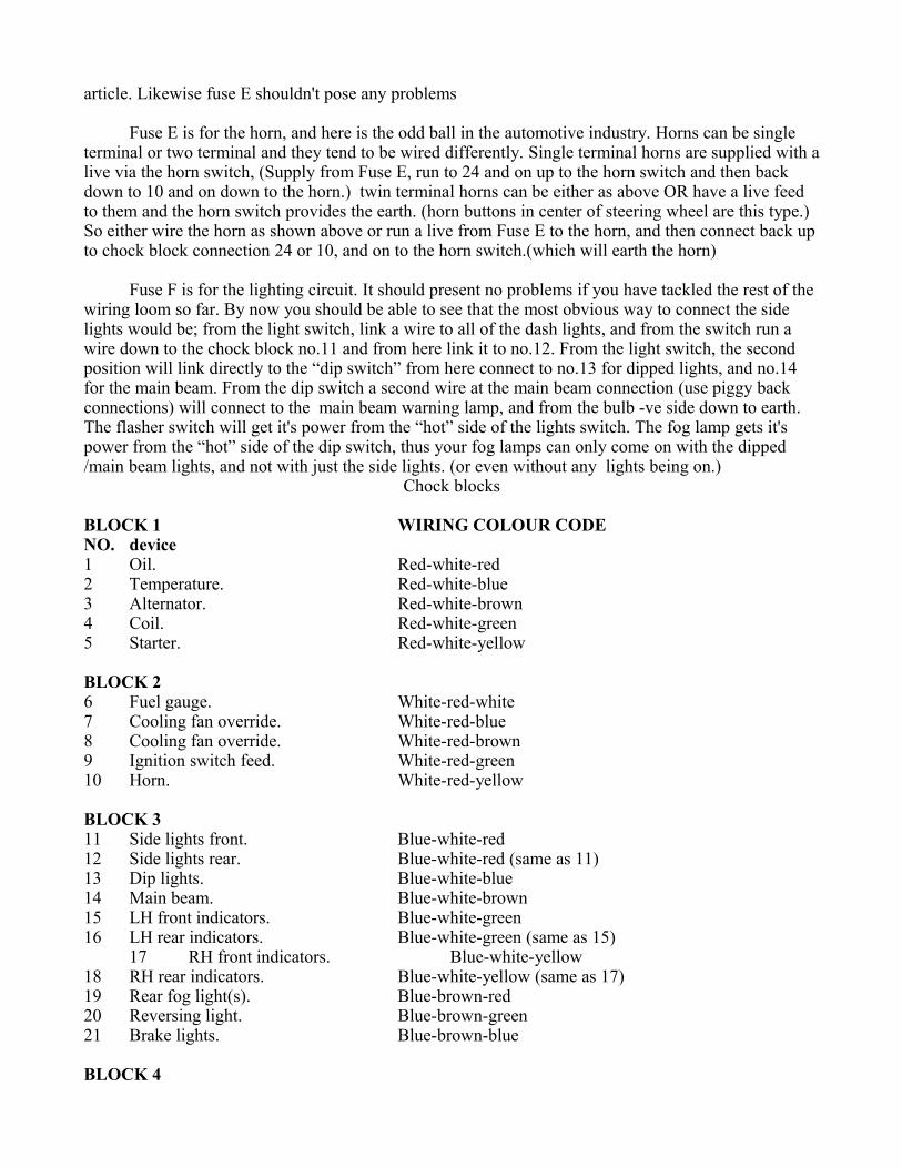
article. Likewise fuse E shouldn't pose any problems
Fuse E is for the horn, and here is the odd ball in the automotive industry. Horns can be single terminal or two terminal and they tend to be wired differently. Single terminal horns are supplied with a live via the horn switch, (Supply from Fuse E, run to 24 and on up to the horn switch and then back down to 10 and on down to the horn.) twin terminal horns can be either as above OR have a live feed to them and the horn switch provides the earth. (horn buttons in center of steering wheel are this type.) So either wire the horn as shown above or run a live from Fuse E to the horn, and then connect back up to chock block connection 24 or 10, and on to the horn switch.(which will earth the horn)
Fuse F is for the lighting circuit. It should present no problems if you have tackled the rest of the wiring loom so far. By now you should be able to see that the most obvious way to connect the side lights would be; from the light switch, link a wire to all of the dash lights, and from the switch run a wire down to the chock block no.11 and from here link it to no.12. From the light switch, the second position will link directly to the “dip switch” from here connect to no.13 for dipped lights, and no.14 for the main beam. From the dip switch a second wire at the main beam connection (use piggy back connections) will connect to the main beam warning lamp, and from the bulb -ve side down to earth.The flasher switch will get it's power from the “hot” side of the lights switch. The fog lamp gets it's power from the “hot” side of the dip switch, thus your fog lamps can only come on with the dipped /main beam lights, and not with just the side lights. (or even without any lights being on.)
Chock blocks
BLOCK 1 WIRING COLOUR CODENO. device1 Oil. Red-white-red2 Temperature. Red-white-blue3 Alternator. Red-white-brown4 Coil. Red-white-green5 Starter. Red-white-yellow
BLOCK 26 Fuel gauge. White-red-white7 Cooling fan override. White-red-blue8 Cooling fan override. White-red-brown9 Ignition switch feed. White-red-green10 Horn. White-red-yellow
BLOCK 311 Side lights front. Blue-white-red12 Side lights rear. Blue-white-red (same as 11)13 Dip lights. Blue-white-blue14 Main beam. Blue-white-brown15 LH front indicators. Blue-white-green16 LH rear indicators. Blue-white-green (same as 15)
17 RH front indicators. Blue-white-yellow18 RH rear indicators. Blue-white-yellow (same as 17)19 Rear fog light(s). Blue-brown-red20 Reversing light. Blue-brown-green21 Brake lights. Blue-brown-blue
BLOCK 4

22 Ignition switch to fuse A,B,C. Green-white-red23 Fuse D (Radio) Green-white-green24 Fuse E (Horn) Green-white-blue25 Fuse F (Lights) Green-white-brown26 Fuse G (Hazards) Green-white-yellow27 Fuse H (Cig. lighter socket) Green-red-green28 Fuse A (Indicators) Green-red-blue29 Fuse B (Wipers, Heater) Green-red-brown30 Washer motor. Green-red-white31 Earth return. Green-yellow (earth tape)32 Handbrake, master cylinder. Green-red-yellow
Connections no. 11 + 12 are linked together. As are connections 15 to 16, and 17 to 18. As could be 20 to 22 if reversing lights are used. (these two are on sepperate chock blocks.)
Once you have all of your connections have been made, gather all your wires together and wrap a short piece of black tape around the loom at various intervals especially at any junction / spur off. The whole loom will need wrapping in something to protect it. The best thing in my opinion is a type of tube cut in a continuous spiral which will easily wrap round the loom. It will make the loom quite stiff and tidy. All that is then required is to secure it to the bodywork / chassis at various intervals. Don't be tempted to use ordinary black insulating tape to wrap the loom as you wont be able to do the job in one go. And as a result it will come undone quite quickly, leaving a sticky mess. Professional wiring looms are wrapped in a kind of black cling film tape, which you may not be able to easily find. You could use long lengths of shrink wrap tube.
Using relays.Most modern cars use switch gear which is not able to handle the current requirements of the
switched consumer, unlike most cars prior to the early 1980's. So as a result it is necessary to use relays to switch the current loads. Relays are basically remotely operated switches and are very easy to add in to any circuit. Relays can be earth switched or live switched (see fig. 3 below) it makes no difference to the relay. Also using two relays in series can make a circuit conditional on two devices being switched on to operate it. e.g. Headlights (but not the sides) only to come on when ignition and side lights are also on. (see fig 4. below.) Relays should be placed near to the fuse box, and need to be properly secured to the body work of the car. Either by the tag on the relay if supplied, or by using a cable tie to the actual relay body it's self. It is not a good idea to just leave them dangling. Another way to make a relay conditional is to choose the switching current to come from a separate fused supply to the consumer load, which may also be switched.

Most relays will have a small wiring diagram printed on their side and very often the terminals will be numbered on the underneath. These numbers will either be some thing simple from 1-4 (or 5) or will follow an international standard, the supply and output connections are numbered 30 + 87, the trigger connections are numbered 85 + 86. Some times you will come across a 5 pin relays, in which case the fifth connection is a second output (87b), this will either be a change over relay, where by activating the relay you switch between output 87 and 87b, or activating the relay will switch both on at the same time. The relay will usually say on its side somewhere.
Fig 4.

Lets take the lights circuit as an example of the need to use relays. In the top most circuit above, I have shown you how to add relays to the dip lights circuit and the main beam circuit. If you are going to add relays in to any circuit it is best to ensure they are supplied by their own separate fuse, hence the fuses are labeled I + J. These are best supplied from the +ve (hot) side of fuses E F G H, the battery supply direct. The lights are powered from the relays not the switch, the switch is used to trigger the relays. Instead of the dip lights and the main beam connecting directly to the chock blocks at no.13 and no.14, connect to the relays, the switches trigger the relays via the chock blocks at 13 and 14. If you were to connect the lights in this way the lights will still come on when the switch is thrown.
If however you would prefer only the side lights to stay on when the ignition switch was off and the lights switch was on (as parking lights) then add the relay shown in the lower half of the circuit drawn above. This will supply the power for fuse I + J. The advantage is, that when the ignition is off then the dip and main beam lights cannot come on because the relays for fuse I + J are not activated. As soon as you turn on the ignition then the lights will come back on. How? Well because fuse A B C are only active when the ignition switch is on, then by connecting the relay to the +ve (hot) side of these causes the relay to come on only when the ignition is also on.