How to order fitting components for looping ribs: Design ... · Construction History Society. ......
13
In; J.W.P. Campbell et al. (ed.), Building Histories: The Proceedings of the Fourth Conference of the Construction History Society. Cambridge, Queens’ College, 7-9 April 2017, p. 159-170 (authors’ manuscript). How to order fitting components for looping ribs: Design procedures for the stone members of complex Late Gothic vaults David Wendland, 1 Frédéric Degenève 2 Introduction The ambitious late Gothic vaults created in the fifteenth and sixteenth centuries, with their complex shape and complicated meshes of ribs soaring along spatial curves, were extremely demanding in their geometric design. This applies to both the design of the whole structure as well as the design specifications for the single stone elements that were prefabricated and fit together on the building site with astonishing precision. The particular character of these structures and their geometric features are intrinsically linked to the design routines and the geometric concepts used by the Master Builders. Fig. 1: Vault with looping ribs, “Hall of Arms” in the Albrechtsburg Meissen, built in 1521 by Jakob Heilmann. Photo M. J. Ventas Sierra, D. Wendland. 1 Technische Universität Dresden, Research Project “REGothicVaultDesign” (ERC), Dresden, Germany. 2 Fondation de l’Œuvre Notre-Dame, Strasbourg, France.
Transcript of How to order fitting components for looping ribs: Design ... · Construction History Society. ......

In; J.W.P. Campbell et al. (ed.), Building Histories: The Proceedings of the Fourth Conference of the Construction History Society. Cambridge, Queens’ College, 7-9 April 2017, p. 159-170 (authors’ manuscript).
How to order fitting components for looping ribs: Design procedures for the stone members of complex Late Gothic vaults
David Wendland,1 Frédéric Degenève2
Introduction
The ambitious late Gothic vaults created in the fifteenth and sixteenth centuries, with their complex shape and complicated meshes of ribs soaring along spatial curves, were extremely demanding in their geometric design. This applies to both the design of the whole structure as well as the design specifications for the single stone elements that were prefabricated and fit together on the building site with astonishing precision. The particular character of these structures and their geometric features are intrinsically linked to the design routines and the geometric concepts used by the Master Builders.
Fig. 1: Vault with looping ribs, “Hall of Arms” in the Albrechtsburg Meissen, built in 1521 by Jakob Heilmann. Photo M. J. Ventas Sierra, D. Wendland.
1 Technische Universität Dresden, Research Project “REGothicVaultDesign” (ERC), Dresden, Germany. 2 Fondation de l’Œuvre Notre-Dame, Strasbourg, France.

D. Wendland, F. Degenève: Components for Looping Ribs
2
Until now, these procedures and methods are not well understood, because they are not documented in original drawings, and because they differ in principle from the modern practice. In consequence, necessary repairs and restoration cannot recur to any information related to the original design. Further, understanding the characteristics of information transfer from the design to the execution would cast a light on the knowledge community in which these constructions were created.
In several case studies, the geometric concepts of the intricate spatial curve systems of late Gothic vaults have been clarified on the basis of detailed surveys and geometrical analyses carried out on the built objects. With this background, the existing sources such as historical design treatises could be re-interpreted as well.
In a collaboration between the research group working on the design principles of late Gothic vaults at the Technische Universität Dresden, and expert stone masons specializing in historical working techniques and practical stereotomy at the Cathedral Workshop Œuvre Notre-Dame de Strasbourg, the essential phases of the design process are currently being investigated in practical experiments – in particular, the execution of full-scale drawings on the tracing floor and the production of full-scale models and samples of ribs and keystones. These experiments are carried out mainly using the example of the vaults built by Jacob Heilmann in the Hall of Arms in Meissen (1521)3
The result of our work is the proposal of a complete picture of the design process from the general concept to the setting-out of the single stone elements. Further, we are able to draw general conclusions about the Late Medieval and Early Modern design practice for stone structures and trace a new interpretation of the early treatises of stereotomy.
and in the Sacristy of St. Anna’s Church in Annaberg (1519) – for the first, the complete executive drawing, double-curved rib voussoirs and selected keystones are reproduced.
Starting Point: Geometrical features of the solids of double curved ribs in late Gothic vaults
In Gothic vaults, the geometric design is based on the definition of the curves of the ribs, which are devised as autonomous curves with simple geometrical terms to which the vault surface is adapted.4
In the German-speaking realm, even in the most complex late Gothic vaults, the curves of the ribs and boundary arches describe circle segments. In consequence, the surface of the shell presents a complex geometry. Late Gothic vaults with looping ribs (Fig. 1) are also conceived of following the same principle, which we could ascertain in analyses carried out on several vaults of this kind from the early 16th century.5
3 cf. D. Wendland, M. Aranda, and A. Kobe, ‘The Vault with Curvilinear Ribs in the “Hall of Arms” in the Albrechtsburg Meissen: Studies on the Concept, Design and Construction of a Complex Late Gothic Rib Vault’, in J. W. P. Campbell et al. (Eds.), Proceedings of the First Conference of the Construction History Society, Queens’ College, Cambridge 2014, pp. 459–468.
Here, the
4 This circumstance has been brought to attention already by scholars in the 19th century. Cf. R. Willis, ‘On the construction of the vaults in the middle-ages’, Transactions of the Royal Institute of British Architects vol. 1, 1842, pp. 1-69. 5 D. Wendland, ‘Arches and Spirals: The Geometrical Concept of the Curvilinear Rib Vault in the Albrechtsburg at Meissen and Some Considerations on the Construction of Late-Gothic Vaults with Double-Curved Ribs’, in R.

D. Wendland, F. Degenève: Components for Looping Ribs
3
spatial curves of the arches are also defined by circle segments in their elevation; additionally, the elevation is curved according to the curvature of the ribs in plan, where they also describe circle segments. This concept can easily be reproduced by drawing a circle segment on a piece of cardboard which is then bent to a vertical cylindrical surface, following the circular plan of the rib ( Fig. 2). We can call these curves enrolled arches, or spirals with a vertical progression described by the circle segment of the elevation.
Fig. 2: The spatial curves described by the ribs: Left, portion of a rib in the “Hall of Arms” with nearly perfect continuity over the joints. Right, model of the geometric definition of the rib curve. Photos M. J. Ventas Sierra, D. Wendland.
The builders of these vaults were capable of realizing the double curvature of the single rib elements and also the continuity of the curvature in the entire ribs with astonishing precision ( Fig. 2). Obviously, this could only be achieved with an appropriate geometric description and with an effective means of transmitting the information.
The definition of the solids of looping ribs according to the enrolled arches, which we find in the analyses of the built objects, turns out to be difficult to conceptualize in the geometric terms which are usually applied in the definition of stone elements. This is due to the fact that
Carvais et al. (Eds.), Nuts and Bolts of Construction History: Culture, Technology and Society, Paris: Picard, 2012, vol. 1 p. 351-357; D. Wendland, ‘Wie haben die spätgotischen Architekten die Kurven der Bogenrippen geometrisch konstruiert?’, in Das Schlingrippengewölbe der Schlosskapelle Dresden, pp. 34-38. Altenburg: Kamprad, 2013; Wendland, Aranda, Kobe (note 1). In these investigations, earlier studies could be confirmed with a broad and reliable database: J. Muk, ‘Die Gewölbe des Benedikt Ried’, vol. 1 pp. 193-205 in R. Graefe, J. Tomlow (Eds.), Geschichte des Konstruierens IV, Wölbkonstruktionen der Gotik, Stuttgart/Tübingen, 1990; W. Müller, N. Quien, Spätgotik virtuell: Für und Wider die Simulation historischer Architektur, Weimar: VDG, 1999, and elsewhere.

D. Wendland, F. Degenève: Components for Looping Ribs
4
the procedures used in the modern stereotomy are based on the projection of the shape to be produced on the perpendicular planes of the cuboid or ashlar. Apart from the obvious difficulty of this construction, it seems implausible to employ projection in the production of an object, which is guided by curves that are in principle not defined by projection but by a very straight-forward procedure that in itself recurs to very simple geometric terms.
On the contrary, as already Werner Müller pointed out, the task seems to have a great affinity with a different approach we can find in the earlier treatises of stereotomy, which is based on the use of flexible templates to be applied on the curved surfaces during the intermediate phases of the preparation of the pieces: “par panneaux”.6
Another possible approach we can use today is the parametric modelling of the rib solid by the translation of the cross-section of the rib along the looping curve of the intrados. However, this procedure is also rather complicated and, in detail, even problematic, as we have explained elsewhere:
7
In general, the procedure we use will have an effect on the shape to be created, and the philology of the working method will compromise the geometrical qualities with respect to the original. For the execution of the work, we must understand how a description of the shape of the rib voussior can be provided in practical geometrical terms, while giving the necessary procedural information for carving the piece from the stone. In fact, it is essential to provide precise and definite information about where to cut in any stage – which in practice means that in every moment it must be possible to trace lines on the piece that indicate where to cut and where to lay the straight-edge.
the curve must be generated in first place (in current CAD applications, one wouldn’t find the option of “enrolled arches”); the vertical but radial position of the sliding cross-section must be additionally controlled; the shape of the rib solid generated in this way doesn’t completely match our observations of the original. Moreover, it is not at all clear how this procedure can offer a clear guideline for cutting the piece from the ashlar.
Taking the idea of using flexible templates, we can develop such a definition by translating the usual procedure of cutting the solids of plane ribs to the specification of looping ribs. This can be supported by observations of the original, where the flanks of the ribs prove to be vertical ( Fig. 3) – meaning, not only the intrados curve, but also the flanks of the voussoirs are inscribed in vertical cylindrical surfaces – in contrast to the outcome of the parametric model mentioned above.8
6 W. Müller, Steinmetzgeometrie zwischen Spätgotik und Barock, Petersberg: Imhof, 2002; D. Wendland and M. J. Ventas, ‘Designing a Masonry Shell in the Reconstructed Vault of the Palace Chapel at Dresden – An Attempt of Recovering the Forgotten Art of Late Gothic Vault Construction’. Informes de la Construcción, vol. 65, 2013, No. extra 2, Construcción Histórica en Piedra / Historic Stone Construction, pp. 49-63; Wendland, Arches and Spirals (note 3); Wendland, Kurven (note 3). 7 Wendland, Aranda, Kobe (note1); D. Wendland, M. Aranda, and M. J. Ventas, ‘El corte de la piedra en bóvedas tardogóticas complejas a la luz de los primeros tratados modernos de estereotomía’, in S. Huerta (Ed.), I Congreso Internacional Hispanoamericano de Historia de la Construcción (Segovia 2015), Madrid 2015, vol. III pp. 1781-1791. 8 Wendland, Aranda, Ventas (note 5).

D. Wendland, F. Degenève: Components for Looping Ribs
5
Fig. 3: Detail of the ribs in the vault of the Sacristy in Annaberg. The vertical laser ray gives evidence of the vertical cylindrical flanks of the rib. Photo M. J. Ventas Sierra.
In plane ribs, the solid of the voussoir can be produced by applying templates that represent the elevation of the rib on the vertical plane flanks. These templates are placed on the sides of the ashlar being prepared according to the width of the rib, the lines of intrados and extrados are traced, and the piece can be cut along these lines. Hence, a rib solid will be produced as a raw part with a rectangular cross section. In the next step, chamfers or facets are cut in a first approximation for the moulding of the rib profile, following lines drawn on the raw piece. The centre lines are applied on the intrados and the surfaces of the bed joints; on the latter, the profile, as well as a straight line over the outline of the moulding, are drawn according to the template that represents the cross section of the rib with its moulding. The lines for the chamfers are traced on the intrados and the flanks by means of a marking gauge.
This procedural definition can be directly translated to the voussoir of a looping rib by inscribing the solid in concentric cylindrical flanks that, in respect to the final position in the arch, have vertical generators – instead of the vertical flanks of the plane rib solid. While in the plane rib, the intrados and extrados of the raw piece are cylindrical, in the looping ribs, they become straight helicoids due to the curvature of the rib in plan. Hence, in the double-curved rib, the intrados is generated by a straight horizontal line that rotates around a vertical axis located at the centre of the curve of the rib in the plan and that slides along the intrados curve of a rib as a directrix. The vertical displacement that generates the surface is therefore not constant but in accordance with the function of the circle segment in the elevation of the
Fig. 4: Geometric description of the rib volume with vertical cylindrical flanks and helicoids at the intrados and extrados. The distortion in the contour of the intersecting plane at the joint can be also observed in the original vault, e.g. in Annaberg, cf. Fig. 3. Left, CAD M. Aranda Alonso; right, M. J. Ventas Sierra.

D. Wendland, F. Degenève: Components for Looping Ribs
6
rib, corresponding to the definition of the intrados’s curve as enrolled arch, as mentioned above. The extrados is generated in the same way, along an extrados curve running parallel above the intrados curve.
Both ends of the single rib voussoir are determined by radial planes that intersect with the rib solid, defining the surfaces of the bed joints. These intersecting planes are positioned in radial inclination according to the intrados curve of the arch. It is interesting to note that the resulting surface is not exactly rectangular; due to the fact that the intersection with the extrados surface is not parallel to the generators of the helicoid, the upper edge is not horizontal, so that the profile is slightly distorted ( Fig. 4).9
In fact, this distortion of the rib section in the plane joint can also be observed on the built object – which confirms the conformity of the proposed geometric description with the original. As we will show, it is possible to easily derive the single steps for dressing the work pieces from this model, including the application of the drawing in every phase of the working process as well.
Elaborating the design specifications on the tracing floor
Generally, in the design of medieval and early modern stone structures, the geometric information was generated with graphic procedures10 in a process carried out on the tracing floor.11 This has an essential influence on the geometric properties of the built objects, in particular also on the curves of Late Gothic vaults: in fact, the entire geometric conception of these complex spatial configurations is rigorously based on constructions which are carried out in the plane.12
9 In contrast to modern stereotomy, the bed joints are defined as planes, not as helicoids, for eminent practical and constructive reasons. In principle, the sides of the joint surface generated by the intersection of the rib volume with a plane are curved. In practice, however, this curvature is not perceivable with the boundary conditions of the surveyed vaults. Therefore, the sides can be approximated by straight edges perpendicular to the lower edge (intrados).
To produce the centring that guides the spatial system of curves during construction, and obtain the necessary information in order to carve the single stone elements exactly to their shape, it is necessary to carry out these graphic procedures in full scale. The “geometric processor” where every dimension can be deduced, all instructions formulated, and in particular the templates produced, is the tracing floor where the interrelating geometric constructions are performed. We produced a tracing floor in order to understand the information flow from design to construction – the characteristic properties of which, we stress, significantly determine the shape of the built artefact. The floor is large enough to draw the plan of the analysed vault in full scale and construct the curves of the all the elevations in the plane, in such manner that their intrinsic relation at the intersection could be accordingly “processed”. Following the examples of the existing historical tracing floors in York and Wells, the floor was made of plaster, and we carried out the drawing with the scribing iron.
10 Müller, Steinmetzgeometrie (note 3) and elsewhere; A. Pacey, Medieval Architectural Drawing: English Craftsmen’s Methods and Their Later Persistance (c.1200-1700), Chalford Stroud: Tempus, 2007. 11 J. Harvey, ‘The Tracing Floor in York Minster’, in The Friends of York Minster, Fortieth Annual Report, 1968, pp. 9-13; W. Schöller, ‘Ritzzeichnungen: Ein Beitrag zur Geschichte der Architekturzeichnung im Mittelalter’, Architectura vol. 19, 1989, pp. 36-61; N. Nußbaum, S. Lepsky, Das gotische Gewölbe. Eine Geschichte seiner Form und Konstruktion, Darmstadt: Wissenschaftliche Buchgesellschaft, 1999. 12 Müller, Steinmetzgeometrie (note 3); Wendland, Arches and Spirals, Wendland, Kurven (note 3).

D. Wendland, F. Degenève: Components for Looping Ribs
7
Fig. 5: Executing the full-scale drawing on the tracing floor. Left, working with the compass; right, measuring the length of the curves in the plan. Photos: M. J. Ventas Sierra.
To understand this procedure, it is necessary to take into account the particular modus operandi on the tracing floor, which is not essentially different from working methods that are also traditionally common among carpenters for setting out a wooden framework. For instance, dimensions are never measured but directly picked up with the compass or rods. Such direct transmission of dimensions, together with the redundant geometric operations, creates a remarkably false-proof system of information. In principle, all geometric constructions are resumed whenever their outcome is produced – here, it turns out to be of great help that the geometric constructions are in themselves very elementary; they are all carried out with straight laths, cords, and the compass. Typically, the compass has two needles, which either scribe the circular line or form the central pivot – with fast switches of these two functions in the frequent double circle strokes to be carried out. Doing this with a compass, which is seven meters long and handled by several people, creates a characteristic movement on the tracing floor that is very reminiscent of a dance ( Fig. 5, left).
After drawing the curved ribs in plan, where they describe circle segments, the elevations of the ribs also have to be drawn – according to the basic principle we have pointed out, their spatial curves are constructed in the plane as simple circle segments as well. In order to obtain the radius of the elevation, and to find the right position for every intersection along the base line of the elevation, it is necessary to establish the length of the entire curved rib as well as the single portion from the plan. In principle, this can be achieved either numerically or by measuring of the drawing. Late medieval master builders were definitely capable of computing the circumference.13
Moreover, the design of the analyzed vaults is mainly based on quadrants, which simplifies the calculation of the curved length to be “developed” for drawing the elevation. But this can also be done graphically, and very simply, on the full scale drawing by pacing out the curved line with a compass (Fig. 5, right). We found that the error margin remains within the working tolerances and that mistakes in counting could be excluded by just repeating the procedure two or three times. Hence, this aspect of the design
13 In his treatise printed in 1486, Mathes Roriczer proposes to multiply the diameter with 3 1/7, which in respect to the working tolerances can be considered as reasonable good approximation. M. Roritzer, Das Büchlein von der Fialen Gerechtigkeit: Facsimile der Originalausgabe Regensburg 1486, Hürtgenwald: Pressler [1965] 1999.

D. Wendland, F. Degenève: Components for Looping Ribs
8
of double-curved rib systems, which at first glance seems difficult and complicated, turned out to be astonishingly simple and reliable in the practical experiment.
In the superposition of the plan and the interrelating elevations, the dimensions of length and height of every element could be established and then marked on thin wooden laths directly on the drawing. The templates are also easily produced on the tracing floor, by just repeating the drawing in situ on copper sheets ( Fig. 6).
Fig. 6: Left: Detail of the drawing on the tracing floor. Right, “tool kit” for transferring the geometric definition of a rib solid: Two baivels and two templates corresponding to plan and elevation, common for all voussoirs, and measuring stick for marking the two end points. Photos M. J. Ventas Sierra, D. Wendland.
From the stone block to the rib segment: The use of flexible templates in Stereotomy.
The geometric information is transferred by means of templates, baivels and measuring rods from the tracing floor to the work pieces. The use of templates is not very common in the modern practice of stone masonry but was apparently very frequent in the late medieval and the early modern stone construction. In discussing the preparation of complex structures such as curved arches, vaults and spiral staircases, the treatises by Philibert de L’Orme and Alonso de Vandelvira give broad insight into the use of flexible templates, and François Derand describes the materials they can be made of.14
The baivel is a square that represents the curved intrados of the arch on one side, and the perpendicular straight line of the radial joint on the other side.
For the production of the stone members of the vaults we analyzed, templates made from copper plates were most likely used.
15
14 Wendland, Aranda, Ventas (note 5). A. de Vandelvira, Libro de trazas de cortes de piedra, facs. with an essay by J. C. Palacios, Madrid: Inst. Juan de Herrera, 2015; P. de l’Orme, Traités d'architecture, Paris: Laget, 1988; F. Derand, L’Architecture des voûtes, ou l’Art des traits et coupe des voûtes. Paris: S. Cramoisy, 1643: p. 3. The traditional use of metal templates is still testified by many samples in the building workshops, e.g. in Strasbourg and York. For the period around 1500 cf. current research by Christian Mai.
This gauge turned out to be very useful in tracing the single voussoirs in the elevation and the curved plan. The earliest pictorial representation can be found in Chartres Cathedral (window dedicated to St. Sylvester, c. 1220), and its use is once more represented in the earlier treatises of stereotomy,
15 This tool was introduced to the scientific discussion by J. C. Palacios, Trazas y cortes de cantería en el renacimiento español, Madrid: Ministero de Cultura, 1990.

D. Wendland, F. Degenève: Components for Looping Ribs
9
in particular Vandelvira. In the case of looping ribs, two baivels are necessary, one representing the circular plan, the other the plane elevation of the un-enrolled arch.
The shape of the cross-section of the rib with its mouldings is given by a wooden template, which is also common in plane rips. Two more templates are needed, which describe the plan of the rib and its developed elevation. Both need not be tailored to the specific length of the particular voussoirs but simply represent the concentric curves of the flanks in the plan, and the intrados and extrados in the elevation respectively. The elevation template must at least be flexible, so copper was used in the experiments.
Moreover, the end points of the voussoir must be defined in height and in curved length. We transferred this information from the tracing floor to the production of the stones by means of thin flexible wooden rods on which these dimensions were marked. These rods are the only individual element to be prepared for each voussoir; in fact, due to the particular features of the curve definition in looping ribs, each voussoir can be only used in its particular position within the arch.16
Fig. 7: Application of the template representing the plan of the rib to the top and bottom of the ashlar (left). After carving the cylindrical flanks, the template representing the elevation is applied (right), in order to draw the curves of intrados and extrados. Photos: M. J. Ventas Sierra.
In the process, first a cylindrical piece is cut from the ashlar, according to the inscribing vertical cylindrical surfaces and guided by the template that represents the plane ( Fig. 7, left). Then, the position of the end points of the voussoir is marked, and accordingly, the second template that represents the elevation is placed on these curved flanks ( Fig. 7, right). The intrados and extrados can be carved along these lines as ruled surfaces. From this, a double curved raw piece is obtained, on which the same procedure of tracing and carving the moulding described above for plane ribs can be carried out, starting from the facets or chamfers. This procedure turned out to be easy to perform and redundant. In contrast to projective procedures, only real points had to be marked, i.e. the position of the joint on the intrados as drawn on the tracing floor.
16 Wendland, Kurven (note 3); Wendland, Aranda, Kobe (note 1).

D. Wendland, F. Degenève: Components for Looping Ribs
10
The fact that the templates for plan and elevation are common to all voussoirs of a rib, constitutes a major difference from the constructions shown in the early treatises of Stereotomy.17
In the case of the “tour ronde”, according to Philibert de L’Orme and Vandelvira, a different set of templates is used for every single voussoir. In contrast, for the components of all looping ribs in the vault of the “Hall of Arms”, just one set of templates had to be provided; the only variation, apart from the individual length of the voussoir, is the position of the elevation template in respect to the directors of the cylindrical flanks. From this, we can conclude that the use of flexible templates, which becomes obsolete in the development of the treatises of stereotomy during the 17th century, is actually a Gothic working method. Completely in line with the design practice of Late Gothic vaults, it is rather difficult to adapt to the geometric concepts associated with the neoclassic architectural language that prevails in the treatises.
Fig. 8: Models of three subsequent voussoirs made with the procedure shown in Fig. 7 and completed to the first facets of the rib profile. The continuity of the curve is comparable to the original, Fig. 4. Photo M. J. Ventas Sierra.
Fig. 9: CAD simulation of the geometric effects of the use of the template shown in Fig. 7, right, with respect to the principle geometric model of the rib volume, Fig. 4. The error margin remains below the execution tolerance. M. J. Ventas Sierra.
In the experiments, the procedure proposed here was easy to perform and completely coherent with working methods stone masons are accustomed to. And it produced voussoirs that compose looping ribs in the same degree of perfection as we can state in the original ( Fig. 8).
17 Wendland, Aranda, Ventas (note 5).

D. Wendland, F. Degenève: Components for Looping Ribs
11
Additionally, the fidelity of the procedure to the theoretic shape of the rib volumes was also assessed by CAD modelling ( Fig. 9), since from a strictly geometrical point of view, the elevation template represents the exact centre of the rib, and not the outlines of the cylindrical flank where we applied it for drawing the intrados and extrados curves. The fact that the lengths of the inner and outer flanks are different is irrelevant because, as we pointed out, the template has an arbitrary length and is positioned at the end points marked on the flanks.18
Given the endpoints, deviations actually occur with respect to the intersection curve of the helicoids that define intrados and extrados of the raw piece and the cylindrical flank, but in the boundary conditions of the looping ribs we reproduced, these remain well below the working tolerance. Hence, on the basis of these assertions, we can say that the procedure is capable of reproducing the shape of the ribs in Late Gothic vaults with sufficient fidelity.
The complex intersection stones
The carving of intersection stones is principally carried out with the same concepts and procedures as the rib voussoirs, using a similar “tool kit” for the geometric control. All specifications are developed on the tracing floor by drawing the plan and the superposed elevations of the intersecting ribs ( Fig. 10). In the elevation, the upper edge is defined, providing the horizontal upper surface which can be seen emerging from the extrados of the vaults.
Fig. 10: Keystone with triple intersection in the “Hall of Arms” in Meissen in the original and the model worked to the facets as first approximation of the moulding. Photos M. J. Ventas Sierra.
The plan projection of the intersection stone, including the centre lines and edges of the intersecting ribs and the lines of the joints on intrados and extrados, is drawn on the top and bottom sides of the ashlar by means of a template. Along the lines of the outermost joint in every direction, the block is cut into a polygonal prism ( Fig. 11). Vertical axes are drawn in the centres and contours of the joining ribs on the faces of the prism, and the heights are marked, transferring them from the elevation on the tracing floor by means of a rod.
18 However, this length difference gave reason for a general criticism against the proposed method: p. 68 n. 37, T. Bauer, J. Lauterbach, and N. Nußbaum, ‘Benedikt Rieds Schlingrippengewölbe auf der Prager Burg: Entwurf – Steintechnik – Kontext’, Insitu, vol. 7 no. 1, 2015, pp. 59-76.
D. Wendland, F. Degenève: Components for Looping Ribs
12
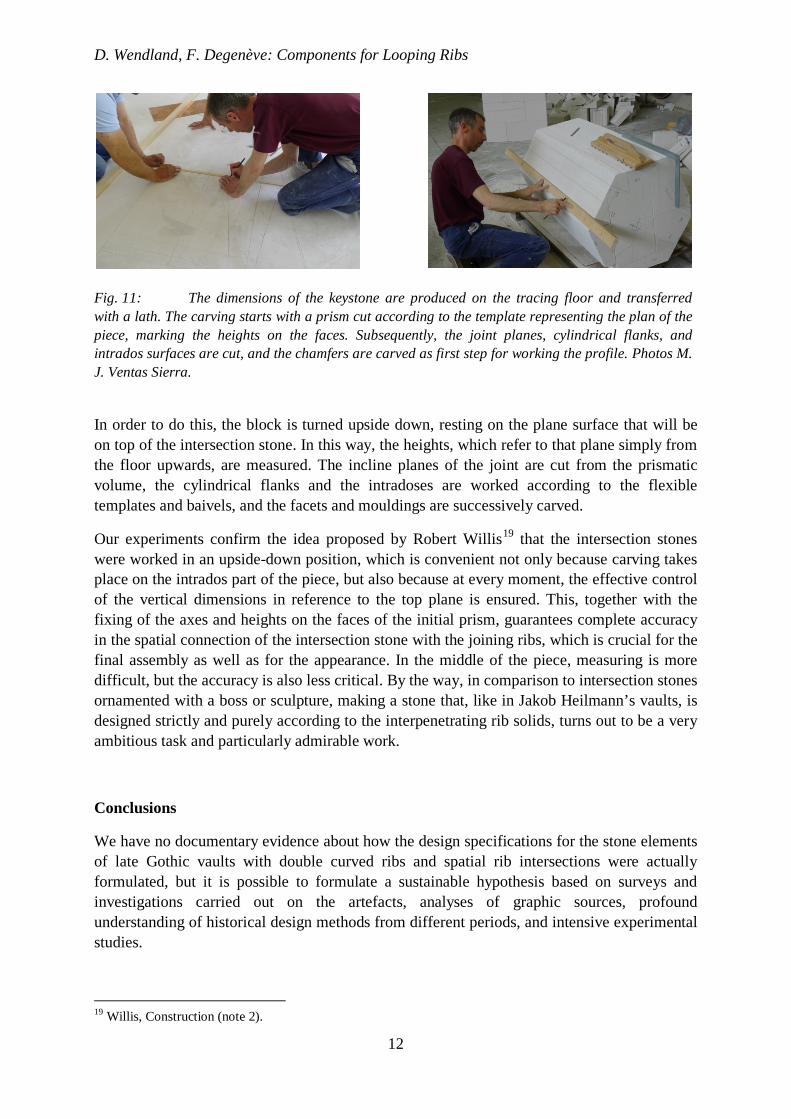
Fig. 11: The dimensions of the keystone are produced on the tracing floor and transferred with a lath. The carving starts with a prism cut according to the template representing the plan of the piece, marking the heights on the faces. Subsequently, the joint planes, cylindrical flanks, and intrados surfaces are cut, and the chamfers are carved as first step for working the profile. Photos M. J. Ventas Sierra.
In order to do this, the block is turned upside down, resting on the plane surface that will be on top of the intersection stone. In this way, the heights, which refer to that plane simply from the floor upwards, are measured. The incline planes of the joint are cut from the prismatic volume, the cylindrical flanks and the intradoses are worked according to the flexible templates and baivels, and the facets and mouldings are successively carved.
Our experiments confirm the idea proposed by Robert Willis19
that the intersection stones were worked in an upside-down position, which is convenient not only because carving takes place on the intrados part of the piece, but also because at every moment, the effective control of the vertical dimensions in reference to the top plane is ensured. This, together with the fixing of the axes and heights on the faces of the initial prism, guarantees complete accuracy in the spatial connection of the intersection stone with the joining ribs, which is crucial for the final assembly as well as for the appearance. In the middle of the piece, measuring is more difficult, but the accuracy is also less critical. By the way, in comparison to intersection stones ornamented with a boss or sculpture, making a stone that, like in Jakob Heilmann’s vaults, is designed strictly and purely according to the interpenetrating rib solids, turns out to be a very ambitious task and particularly admirable work.
Conclusions
We have no documentary evidence about how the design specifications for the stone elements of late Gothic vaults with double curved ribs and spatial rib intersections were actually formulated, but it is possible to formulate a sustainable hypothesis based on surveys and investigations carried out on the artefacts, analyses of graphic sources, profound understanding of historical design methods from different periods, and intensive experimental studies.
19 Willis, Construction (note 2).

D. Wendland, F. Degenève: Components for Looping Ribs
13
The proposed procedure is in full accordance with the geometric concepts that we observe in the studies of the built objects, the analysis of contemporary architectural drawings, and treatises. It accurately reproduces the shape and geometrical features of the original artefacts – in the same degree of perfection, including characteristic particularities that we also encounter in the surveys such as, for instance, the distortion of the profile in the joint plane. Moreover, it can be contextualized within the historical design procedures, planning practices, and geometric concepts in the architecture belonging to the period of transition between medieval and early modern periods.
We are therefore able to put forward for discussion a comprehensive picture of the design of Late Gothic vaults, ranging from the general concept to the setting-out and production of the single stone elements, with a viable procedure for the reproduction in practice. After the conclusion of the experimental phase, practical trials with this procedure are presently being carried out in collaboration with several cathedral workshops and professional schools.
The aim is to provide, on a scientific basis, the necessary information and practical indications of the use for restoring stone structures, employing interventions based on a philological understanding of the historical design practices. The implementation of this information at the collaborating institutions is also meant to be a contribution to the preservation of historical technical knowledge, which we consider an immaterial cultural heritage.
Acknowledgements
The experimental investigations were carried out by the authors together with Nicolas Eberhardt and Christian Mai, as well as María José Ventas Sierra, who prepared the design specifications and performed a CAD simulation of the process. The experiments are performed within the ERC Proof of Concept Grant “Late Gothic vaults and their complex stone members: Recovering historical design procedures, implementing knowledge in restoration practice” (N° 693779) which receives funding from the European Research Council, at the Technische Universität Dresden, in collaboration with the Fondation de L’Œuvre Notre-Dame de Strasbourg, Münsterbauhütte Freiburg and Fachschule für Steingestaltung an der Friedrich-Weinbrenner-Gewerbeschule Freiburg i.Br., Dombauhütte Köln, and Dombauhütte Passau. The scientific bases have been previously prepared within the ERC Starting Grant “Design Principles in Late-Gothic Vault Construction - A New Approach Based on Surveys, Reverse Geometric Engineering and a Reinterpretation of the Sources” (N° 284373, P.I. D. Wendland).
We wish to thank John David, Master Mason of York Cathedral, for providing the opportunity to study the historical Tracing Floor at York Cathedral and Jessica Buskirk for revising the text of this paper.