How to Operate a HAAS VF4 - Dylan...
25
How to Operate a HAAS VF4 Be able to start creating parts like these!
Transcript of How to Operate a HAAS VF4 - Dylan...

How to Operate a HAAS VF4
Be able to start creating parts like these!


Table of contents iii
Table of Contents Table of Contents ....................................................................................................................... iii
Introduction ..................................................................................................................................... 1
Starting Up the Machine ................................................................................................................. 3
Warming up the spindle .............................................................................................................. 3
To Start Up the Machine ............................................................................................................. 3
Setting a Tool .................................................................................................................................. 6
How to properly set a tool ........................................................................................................... 6
Finding Center of a Part .................................................................................................................. 9
Video provides ............................................................................................................................ 9
To make your .............................................................................................................................. 9
Loading and Running a Program .................................................................................................. 13
Index ............................................................................................................................................. 17


1
Introduction
This manual will instruct you how to operate a HAAS VF4 CNC Milling Machine. The
instruction will guide you to be able to:
1. Start up the machine
2. Load a tool
3. Find center of the X and Y-axis of the part
4. Find Z- zero of the part
5. Load and run a program.
Things you need to know,
How to install a tool into an appropriate holder
How to read a Dial Indicator
How to read and interpret basic G and M coding.
What you will need,
Dial Indicator
Machine tools and holders
Floppy disk containing a CNC program
This is not for learning how to create, or edit a program using G and M coding.


Fly Ch.1


Starting Up the Machine 3
Starting Up the Machine
Warming up the spindle You need to warm up the machine to make sure no internal parts are subject to break. The
internal gears of the spindles transmission, when cold, can shatter if the machine is immediately
put to use to machine some materials. For this matter, it is wise to treat it as if you were always
going to be machining tough materials.
To Start Up the Machine
1. Press the Power On button, figure 1 and wait for a beep.
2. Twist and pull the Emergency Stop button, figure 2.
3. Press the Reset button until all alarm codes are off the screen.
4. Press the Power Up Restart button and let the machine find it’s zero origins.
Figure 1
Figure 2
Figure 3
Figure 4

4 HAAS VF4 Operations Manual
5. Press the Manual Data Input (MDI) button, figure 5, and type in “S1500 M03” using the
alpha numeral keys figure 6, and press Write/Enter, figure 7.
6. Press the Cycle Start button, figure 8. The spindle will turn on at 1500 revolutions per
minute in the clockwise direction allowing it to warm up.
7. Press the STOP button to stop the spindle, figure 9. Wait at least ten minutes before
stopping the spindle.
Figure 5 Figure 6 Figure 7
Figure 8
Figure 9

Starting Up the Machine 5
Fly page Ch.

6 HAAS VF4 Operations Manual
Figure 10
Setting a Tool
It is critical to properly set a tool so that the CNC machine knows exactly where the tip of
the tool is. If this value is wrong, whatever part you are trying to machine will be wrong.
How to properly set a tool 1. Locate and install the tool in the appropriate holder.
2. Press the Manual Data Input (MDI) button, figure 10, and type in T(the number
associated with the tool) and then press the Automatic Tool Changer Forward (ATC
FWD) Button. For Example, type in T1 in the MDI screen and press ATC FWD. This
will bring up the correct pocket for the tool.
3. Load the tool by first removing any tool that may be in the spindle of the machine. Make
sure the spindle is not on, press the Tool Release button, figure 11, and simultaneously
hold onto the tool making sure it does not fall onto the table and possibly break.
4. Hold the tool into place on the spindle using one hand, and press the Tool Release button
with the other, figure 11
5. While holding down the Tool Release button, rotate the tool so that the notches of the
holder align with the guides of the spindle. Figure 12&13.
Figure 11
Figure 12

Setting a Tool 7
Figure 13
Figure 16
Figure 15
Figure 14
6. Apply upwards pressure on the tool and align the notches correctly, figure 13, let go of
the Tool Release button, and the spindle will have locked the tool in place.
7. Press the MDI button, type in G128 and press Write/Enter. G128 is a 5” offset already set
into the machine so it can know where the tip of any tool is according to the table.
8.
Press Handle Jog, figure 14, and press the Page Up or Page Down button until you find
the Oper screen. This screen tells you coordinate of where the tool is according to where
you want your origin to be.
9. Next, place the 5” dial indicator under the tool and use the Jogging Handle, figure 15, to
jog the X, Y, and Z axis to move the table so that the tool is directly over indicator.
10. Use the Z axis button carefully to jog down the tool so that the indicator reads exactly
zero by using the .0001” increments button.
11. Navigate to the tool offset menu by pressing the offset button, figure 16, while keeping
the tool on the indicator. Page up or down to get to the offset tool page.

8 HAAS VF4 Operations Manual
12. Locate the tool you are setting by pressing the arrow keys. Arrow over to the Tool Length
Offset, figure 17&18, for the tool and press Tool Offset Measure. The value will be a
negative and exactly 5” less then what the Z Position says.
13. Handle Jog up in Z until you are a safe distance above the part, press the MDI button, and
type in the next tool number you need to set. (For example T2) Press the ATC FWD
button and the next pocket associated with the tool will be in the spindle.
14. Repeat process for every tool until all tools are set.
Figure 17 Figure 18
Finding Center of a Part 9
Finding Center of a Part
Video provides a powerful way to help you prove your point. When you click Online Video, you can paste in
the embed code for the video you want to add. You can also type a keyword to search online for
the video that best fits your document.
To make your
1. Put the stock in the vise on the table and tighten the vise to hold it in place.
2. Locate and install an Edge Finder tool into a collet.
3. Press MDI and press ATC FWD until an empty pocket comes to the spindle, and Install
the tool into the empty pocket by pressing the Tool Release Button and aligning the
notches.
4. Type in “S1500 M03” in the MDI screen. The tool will be a little wobbly at the tip.
5. Press the Handle Jog button and carefully jog the X, Y, and Z axis so that the tip of the
tool is behind and below the part.
6. Use the Y-Axis jog button to bring the tool to touch the back of the part.
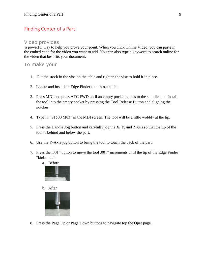
7. Press the .001” button to move the tool .001” increments until the tip of the Edge Finder
“kicks out”.
a. Before
b. After
8. Press the Page Up or Page Down buttons to navigate top the Oper page.

10 HAAS VF4 Operations Manual
9. Press the Origin button while the Y axis is still blinking, figure 19.
10. Jog the spindle up in the Z axis so that the tip of the tool is a safe distance from the top of
the part.
11. Jog in the Y and Z axis so the tool is in front and below the part.
12. Repeat steps 7 and 8.
13. Look at the new Y value in the Oper page, divide it by 2.
14. Use the Jog Handle and the Y and Z axis to bring the Y value to the exact number you
got. This will bring the tool to be at the exact center of the part.
15. Press origin while the Y axis is still blinking.
16. Press the Offset button and Page Up or Page Down to the Work Offset page, and
highlight which G offset you are using in the program, figure 20.
17. Navigate over to the Y axis and press the Part Zero Set button. This tells the machine that
this is where the center of the Y axis of the part.
18. Repeat steps 5 through 17 but use the X instead of the Y axis for finding center of the X
axis.
Figure 19
Figure 20

Fly 11


Loading and Running a Program 12
Loading and Running a Program


How to Run and Operate a HAAS VF4 13


How to Run and Operate a HAAS VF4 13
Index Themes, iii, 3, 4, 5, 6, 9, 10, 11, 12, 13, 14, 15, 16


How to Run and Operate a HAAS VF4 13