How To Deploy SME Network V1.0 - JOYCE ČR, s.r.o. · In this document we briefly describe the...
11
Version 1.0 Page | 1 How to Deploy SME VoIP System (Capacity Planning/Deployment) Contents Contents............................................................................................................................................................. 1 Document History .............................................................................................................................................. 1 Introduction ....................................................................................................................................................... 1 Intended Audience............................................................................................................................................. 2 Abbreviations ..................................................................................................................................................... 2 References ......................................................................................................................................................... 2 Network Requirements...................................................................................................................................... 3 Deployment Considerations .............................................................................................................................. 3 Capacity Planning............................................................................................................................................... 4 Site Planning / Cell Coverage ............................................................................................................................. 4 IP Network ......................................................................................................................................................... 5 Base station/Repeater Placement Strategy ....................................................................................................... 6 Deployment of SME VoIP Network .................................................................................................................... 8 Verify Deployment ...................................................................................................................................... 11 Document History Revision Author Issue Date Comments 0.1 MYA 28-Sep-2010 Initial Version 0.4 JMG 08-Nov-2011 Misc. updates 1.0 Introduction
Transcript of How To Deploy SME Network V1.0 - JOYCE ČR, s.r.o. · In this document we briefly describe the...

Version 1.0 Page | 1
How to Deploy SME VoIP System
(Capacity Planning/Deployment)
Contents
Contents ............................................................................................................................................................. 1
Document History .............................................................................................................................................. 1
Introduction ....................................................................................................................................................... 1
Intended Audience............................................................................................................................................. 2
Abbreviations ..................................................................................................................................................... 2
References ......................................................................................................................................................... 2
Network Requirements...................................................................................................................................... 3
Deployment Considerations .............................................................................................................................. 3
Capacity Planning ............................................................................................................................................... 4
Site Planning / Cell Coverage ............................................................................................................................. 4
IP Network ......................................................................................................................................................... 5
Base station/Repeater Placement Strategy ....................................................................................................... 6
Deployment of SME VoIP Network .................................................................................................................... 8
Verify Deployment ...................................................................................................................................... 11
Document History
Revision Author Issue Date Comments
0.1 MYA 28-Sep-2010 Initial Version
0.4 JMG 08-Nov-2011 Misc. updates
1.0
Introduction

Version 1.0 Page | 2
In this document we briefly describe the elements involved in planning and designing a typical SME
VoIP system. Network planning and deployment process vary from region to region and this document
provides the simplified design procedure.
Network deployment begins with the collection of network requirements of capacity, coverage and
quality.
Intended Audience
The target audience for this document includes network administrators and anyone that will plan and
design a typical SME VoIP network.
Abbreviations
For the purpose of this document, the following abbreviations hold:
DHCP: Dynamic Host Configuration Protocol
(T)FTP: (Trivial) File Transfer Protocol
IOS: Internetworking Operating System
NAT: Network Address Translator
PCMA: A-law Pulse Code Modulation
PCMU: mu-law Pulse Code Modulation
RSSI: Received signal strength indication
RTP: Real-time Transport Protocol
RPORT: Response Port (Refer to RFC3581 for details)
SIP: Session Initiation Protocol
SME: Small and Medium scale Enterprise
STUN: Session Traversal Utilities for NAT
VLAN: Virtual Local Access Network
TOS: Type of Service (policy based routing)
URL: Uniform Resource Locator
UA: User Agent
UTC: Coordinated Universal Time (similar to GMT format)
References [1]: How to Setup SME Network Version 0.3
[2]: Adding Multiple Base station to Network Version 0.4
[3]: Detail Description of Deployment Kit Version 0.1

Version 1.0 Page | 3
Network Requirements
Network requirement is essential to determine elements necessary to achieve the overall expectations
of the customer. Typical network requirements includes (but not limited to):
• The geographical area to be covered
• The type or architecture of building and/or topology, etc. This includes the material of walls,
thickness of walls.
• The estimated traffic in each coverage area
• The blocking criteria in each coverage area.
Deployment Considerations
The following radio related considerations must be examined before deploying a typical SME VoIP
System. These includes (but not limited to):
Building Penetration:
When a signal strikes a building it is diffracted or absorbed; therefore to some extend the signal is
reduced. The amount of absorption is dependent of the kind of building and its environment, the
amount of solid structure. This is an important consideration in coverage planning.
Interference Sources:
Signals from receiving antennas are weakened by virtue of interference from other signals. These
signals may be from the same network or other man-made objects. A well planned SME VoIP system
installation should identify potential interference sources for optimal placement of Base stations and
repeaters.
Radio/Cell Range:
The suggested distance between two base stations depends on the physical path between the base
stations. If the path loss is lessened, e.g. by minimizing amount of walls/obstacles in the path, then
signals from base stations will cover more distance. In a typical office building the suggested distance
between two base stations is 30-40m.
Version 1.0 Page | 4
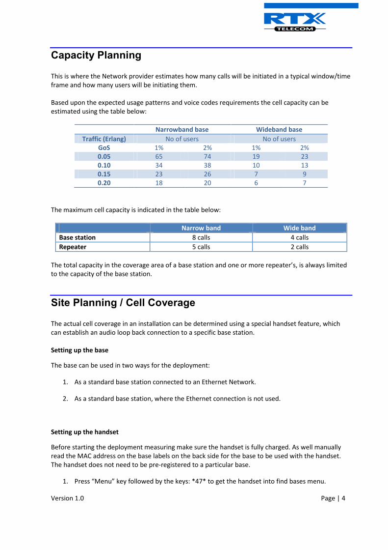
Capacity Planning
This is where the Network provider estimates how many calls will be initiated in a typical window/time
frame and how many users will be initiating them.
Based upon the expected usage patterns and voice codes requirements the cell capacity can be
estimated using the table below:
Narrowband base Wideband base
Traffic (Erlang) No of users No of users
GoS 1% 2% 1% 2%
0.05 65 74 19 23
0.10 34 38 10 13
0.15 23 26 7 9
0.20 18 20 6 7
The maximum cell capacity is indicated in the table below:
Narrow band Wide band
Base station 8 calls 4 calls
Repeater 5 calls 2 calls
The total capacity in the coverage area of a base station and one or more repeater’s, is always limited
to the capacity of the base station.
Site Planning / Cell Coverage
The actual cell coverage in an installation can be determined using a special handset feature, which
can establish an audio loop back connection to a specific base station.
Setting up the base
The base can be used in two ways for the deployment:
1. As a standard base station connected to an Ethernet Network.
2. As a standard base station, where the Ethernet connection is not used.
Setting up the handset
Before starting the deployment measuring make sure the handset is fully charged. As well manually
read the MAC address on the base labels on the back side for the base to be used with the handset.
The handset does not need to be pre-registered to a particular base.
1. Press “Menu” key followed by the keys: *47* to get the handset into find bases menu.

Version 1.0 Page | 5
2. Use the cursor down/up to select the base MAC address for the base
3. Press right softkey “ok” to select the base. Press left softkey “Cancel” to cancel the operation.
4. The handset display will show the “RSSI” level of the base.
5. By pressing “hook off” key (green key) an audio loopback connection will be established with
the base station.
6. By plugging in a headset modified for a MP3 player connection audio from the handset/MP3
player will be looped back to the handset Earpiece. This makes it possible to listen to audio at
the same time as reading the RSSI levels of the display.
7. Alternatively press the center softkey “Tone” to send a tone to the base – and get the tone
playback for the earpiece/speaker or pluged in headset. Press softkey “Tone off” to stop the
tone play.
Handset coverage planning
The purpose of this section is to shortly describe how to plan the base position and handset coverage
from this position.
• Place the RTX86xx base station exact at the desired position and power on the base.
• Set up the handset as described in section 1.3.
• Use the building plan drawing and check the base station coverage using the handset and
headset music signal. Mark up the acceptable spots and non-acceptable spots on the plan
drawing. As well note the RSSI level from the base.
Placing 2nd
base station
In order to place the 2nd
base station:
• Place the 1st
RTX86xx base station exact at the desired position, and power on the base
• Set up the handset as described in section 1.3.
• Use the building plan drawing and check the base station coverage using the handset RSSI
levels. Mark up the acceptable spots and non-acceptable spots for placing the 2nd
base station
on the plan drawing. Acceptable spots are spots where the handset shows RSSI levels better
than -75 dBm.
Typically, installations such as office buildings, hotels and hospitals should be equipped with both base
stations and repeaters on several floors to create uniform and complete radio coverage. Open areas
can be covered with a sparse network of base stations. In such applications, the base stations and/or
repeaters cover an extended range due to the extended line-of-sight radio propagation capability
IP Network

Version 1.0 Page | 6
The SME system can operate using a variety of the IP network settings, allowing it to be configured for
different networks.
The base station can be configured for either dynamic IP-adr retrieval using DHCP or setup for usage of
a fixed IP-adr. The default operation is dynamic retrieval.
The base station can also be configured for usage of a virtual LAN (VLAN), which is the recommended
configuration, as a dedicated VLAN for voice traffic in a corporate network will provide the most
optimal Quality Of Service (QoS). No VLAN tag is enabled as default.
Dedicated QoS settings in the IP packets for support of DiffServ, ToS and also be enabled using the
base station configuration page.
The communication between the base stations and be configured as either IP Multicast or Peer-To-
Peer communication. IP Multicast is the preferred option as it generates the least traffic, but it
requires either a single IP subnet or IP-Multicast pass-through in the network switches.
Base station/Repeater Placement Strategy
The antennas in the base stations are close to omnidirectional; thereby there is no need to consider
how the base stations face each other when deploying them.
There is no one strategy for deploying base stations. These are some recommended Base station
and/or Repeater placement strategies:
Around Corridors:
Base stations/repeater should be deployed vertically preferably at corridor intersections where
propagation patterns follow the corridor patterns. In case there are high objects in the area, the base
station/repeater should be installed above those objects.
Multi-Storey Buildings:
Base stations and repeaters can be installed on opposite sides of the floors to take advantage of the
floor-to-floor coverage. The coverage design cannot rely entirely on floor-to-floor propagation; each
case must be verified due to variations in local attenuation patterns.
Large Halls:
Base stations and repeaters can be deployed in large halls that contain a central open space area with
windows to the other areas. This provides a good coverage for the rooms in the inner circle on all
floors (e.g. hotels).
In large halls, Base stations/repeater should be installed vertically in the middle of the space below the
drop ceiling.
Mounting Positions:
When Base stations and repeater are mounted vertically on a wall, the radio coverage in front of these
devices is twice as large as the coverage at the rear. The base stations should always be mounted
higher that the obstructive objects in the area – e.g. minimum higher than 2m above floor.
Repeaters should be installed in the middle of corridors and small rooms.
Metallic Structures/Objects:
Base stations and repeaters should not be deployed near large metallic objects.

Version 1.0 Page | 7
Reinforced Concrete Structures:
These structures have a high attenuation factor inside the building. They reduce the radio coverage
range of the Base stations and repeaters and therefore require a higher number of base stations or
repeaters in the building. Lighter types of construction materials require fewer base stations since
attenuation figures are considerably lower.

Version 1.0 Page | 8
Deployment of SME VoIP Network
In this chapter we provide short description of practical cases of how SME VoIP network can be
deployed.
Case ##1: Synchronisation Chain with One Master Sync.
a) The Synchronisation chain must always overlap with other Base stations in order to latch each
other in Sync.
b) In this illustration Base station ##39 is the Sync Master
c) A maximum of 7 sync levels (Including the master bases) can be used in a deployment.
d) The other slave base stations or repeaters are connected to the Sync Master through the
synchronisation chain
e) If one of the base or repeater units in the sync chain is broken or not working, then the units that
follow the non-working device are cut off from the sync chain, and air-interface synchronization
can be lost. When the air interface synchronization is lost handover between the two clusters is
not possible.
The sync level concept is illustrated below, where bases #08 and #02 are at sync level 1, and BS#03 is
at level 2.

Version 1.0 Page | 9
Case ##2: Synchronisation Chain without Alternative Sync Paths
a) Assuming Master Sync source is Base station ##39. A maximum of 40 base stations can be
deployed in one setup (depending on the network requirement not all base stations should be
chained).
b) A maximum of 7 sync levels can be used in any deployment.
c) Depending on the system setup, it is recommended to place the Sync source Master in the middle
of the building and to assign numbers/addresses, radio ID (RPN), etc. to each base station or
repeater for easy identification.
� Continuous line: Shows the primary sync paths, with the relevant bases chained in the multi-
cell network.
� Dotted line: Alternative sync paths.
Case ##3: Synchronisation Chain with Alternative Sync Paths The illustration below shows a multi-cell network with alternative Synchronisation paths. A failure of
one base unit does not mean handset or users cannot perform handovers to other active cells.
BS#39 is the SYNC Master, if BS#05 is down, most user handovers can be formed via 3 other
alternative cells (i.e. BS#06, BS#02 and BS#04) without any problems at all.
Furthermore observe the following:
� BS#04 and BS#01 are Primary with alternative sync to BS#39.
� BS#05 is primary sync to BS#04 while alternative sync is BS#01 or BS#02
� BS#03 is primary sync to BS#02 while alternative sync is BS#05 or BS#06, in that order

Version 1.0 Page | 10
In the illustration below:
� BS#24 is primary sync to BS#25 while alternative sync is BS#20
� BS#22 is primary sync to BS#20 while alternative sync is BS#21 or BS#23, in that order

Version 1.0 Page | 11
Verify Deployment The actual synchronization RSSI may be read on the base webpage. It is recommended to have a RSSI
value better than/equal to -75dBm, and never below -90dBm. Below is an example of this, which is a
screen shot from the base station web page
Figure 1: Example of DECT synchronization chain