How To Build a REAL Dalek -...
24
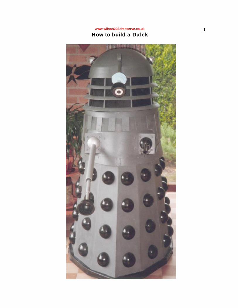
www.wilson203.freeserve.co.uk 1 How to build a Dalek
Transcript of How To Build a REAL Dalek -...
www.wilson203.freeserve.co.uk 1 How to build a Dalek

www.wilson203.freeserve.co.uk 2
Introduction
Having struggled so hard to produce my own Dalek, I thought that it was about time someone produced some decent instructions. The
instructions printed in the Radio Times are the best we've had, and they are completely useless. However, I took hints from them during
construction as well as bunging in some of my own lateral thought, and I have now decided to make my own set of instructions so that others can benefit from my mistakes, problems and anything else I encountered.
WARNING! Before you start, read through each part of the
instructions to make sure that you have the facilities required. If, for example, you suddenly find that you don't have a vacuum former
halfway through the base section and can't think of any other way of producing hemispheres, you'll have an unfinished Dalek on your hands,
and even the most sympathetic family members are likely to order you a skip...
The Dalek can be treated as four sections:-
• The skirt
• The shoulders
• The neck
• The head
These instructions deal with each of these sections in turn. I built my Dalek bottom up, although the other instructions suggest a top-down
approach. Either way is probably just as good, except that if you make the base too weak and the shoulders too heavy, you have a fair chance of destroying several weeks' worth of effort if you have built the base

www.wilson203.freeserve.co.uk 3 first! Another point worth mentioning is that if you have a group of
people building a Dalek, you could build all the parts in parallel.
Although my Dalek is done in the typical grey and black colour scheme used throughout the 1970s, these instructions can be used to build
virtually any Dalek. Exceptions are the Imperial Daleks from Remembrance and the Daleks from the films, as these have major
differences, such as the base and the dome lights.
1. The Skirt
This is certainly the easiest part to build, assuming that you can make all those hemispheres! The best way to go about this is to build it in three
layers, consisting of the frame, the panels and the spots.
The frame
From the photographs, this is clearly not quite the same as the frame in the Radio Times instructions. For a start, I have added the small luxury
of a seat, which was a rather stupid omission! Also, there is some beading round the base to make it easier to fix the panels. The more observant readers may have noticed that I designed it in two halves;
this was not intentional but turned out to be vital, as the skirt section is too wide to go through the average domestic door!1 Also, the fact that I

www.wilson203.freeserve.co.uk 4 couldn't get a piece of MDF large enough to do the whole base (well,
not into the car, anyway!) was a limiting factor. The two halves are held together by latches at the top and some funny joint which has a name I
can't remember at the bottom. Both halves run on three castors, as used in swivel chairs. This means that it runs fine on smooth surfaces and
carpet, but tarmac is a nightmare! If you want an all-terrain Dalek, you can get better castors but they may be too large and lift the base too
far off the ground.
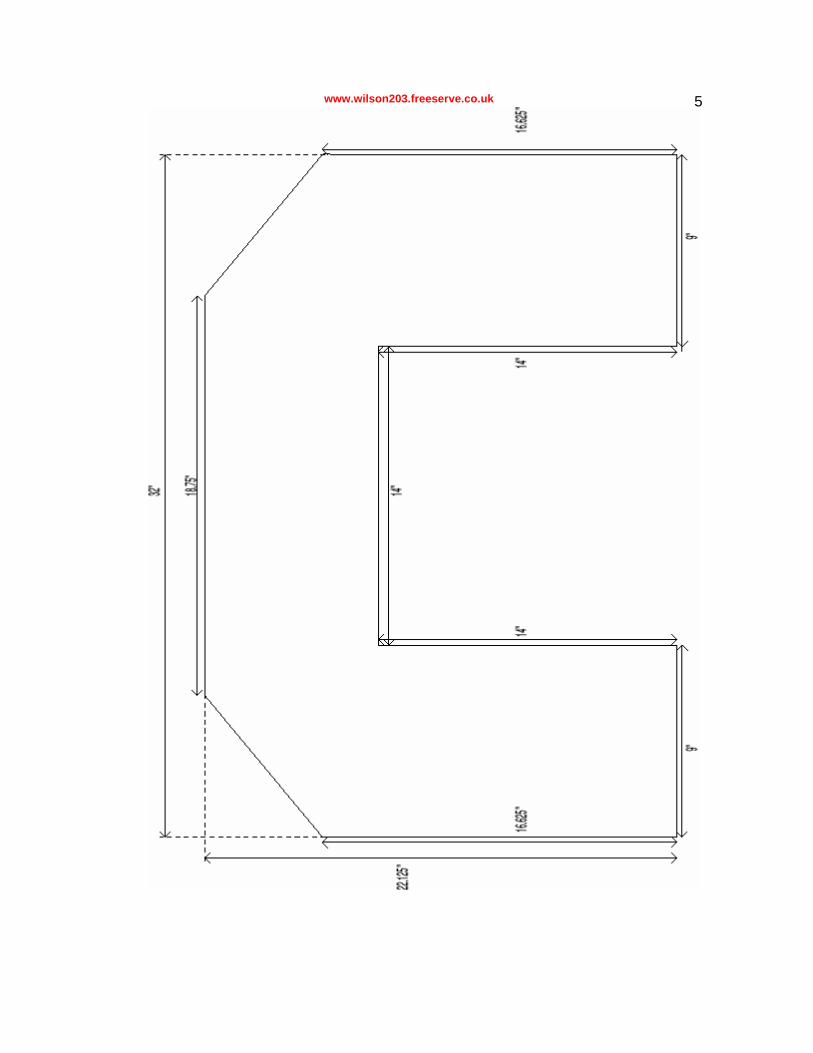
The measurements for the pieces are given on the following diagrams. I also use two supporting struts for the front, but the measurements for
these are not important as long as they are the same height as the other supports. Another point worth making is that the front support
has to be sanded to a V-shape to allow the front panels to fit.
I constructed the base and supports from 15mm MDF and the top from 3mm hardboard. I would have used MDF for the whole lot, but we had
a nice sheet of hardboard lying around so I decided to use it.
www.wilson203.freeserve.co.uk 5

www.wilson203.freeserve.co.uk 6
The front half is a bit more tricky and I'm not sure that I've got the angles entirely accurate. The V-shape at the back is just designed to add a bit of foot room and is unimportant. You can use whatever size
you think appropriate or just leave it out. To keep the two halves of the
www.wilson203.freeserve.co.uk 7 base together, I suggest using a latch system from a cupboard. This way, they should just lock when pushed together and prevent the base
from coming apart.
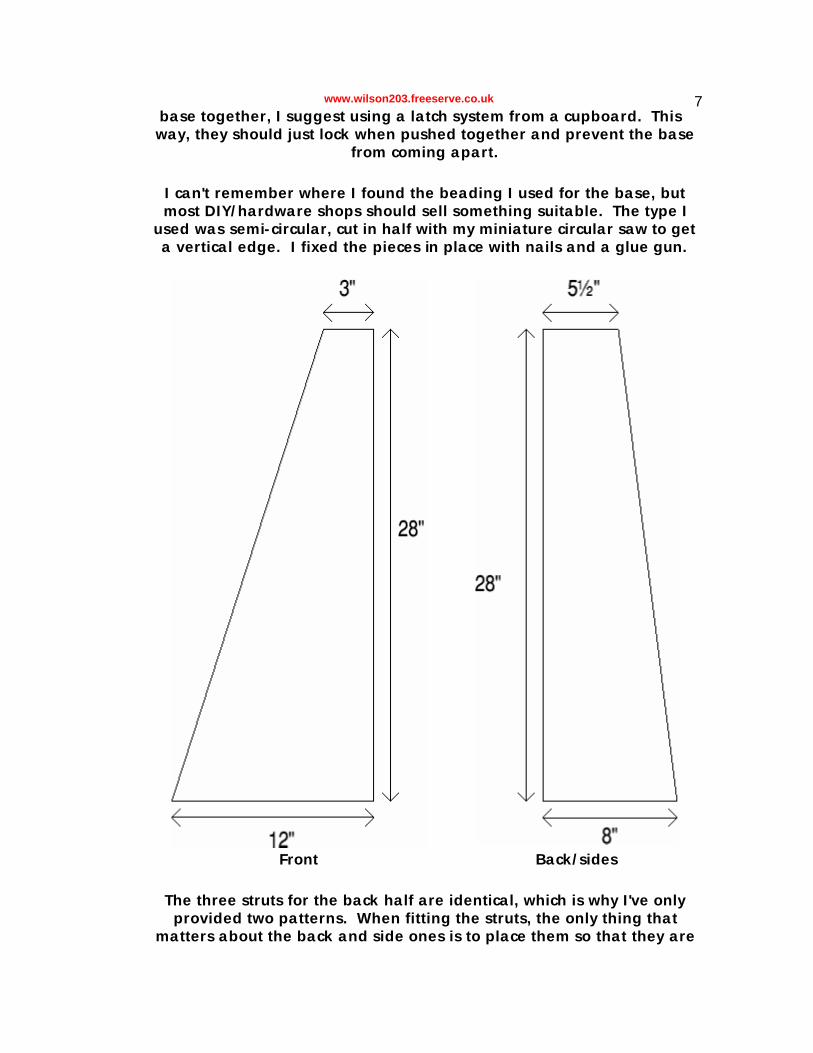
I can't remember where I found the beading I used for the base, but most DIY/hardware shops should sell something suitable. The type I
used was semi-circular, cut in half with my miniature circular saw to get a vertical edge. I fixed the pieces in place with nails and a glue gun.
Front Back/sides
The three struts for the back half are identical, which is why I've only provided two patterns. When fitting the struts, the only thing that
matters about the back and side ones is to place them so that they are

www.wilson203.freeserve.co.uk 8 exactly an inch from the edge of the base. Conveniently, this means
that the side ones should line up with the hole in the middle. Common sense should tell you to put the back support in the middle, and I would
suggest putting the side ones at a distance of 7" from the ends. The front strut is slightly trickier to place, as it has to be 1 inch from the edge
at the closest point. If you attach the beading first, you may find it easier to judge. I attached the struts with screws (and a couple of blocks
to stabilise them).

www.wilson203.freeserve.co.uk 9
The top of the skirt is similar to the bottom, built in two halves with the cut out section so someone can fit through. To hold the two halves together, I mounted two latches on two pairs of blocks as shown. I attached the struts and blocks to the top sections with countersunk screws. Again, the V-shape in the front half can be any size you
want.
A seat can easily be added at this stage by taking a small plank of
wood (in my case, it was a left-over bit of shelf) and cutting two slots so it will fit between the side struts. After determining a sensible height,
screwing a couple of blocks to the struts should keep it supported.
Finally, you need to add 6 castors- 3 for the front and 3 for the back. The type of castors you use determines the sort of terrain your Dalek can
cross. They must be at least swivel-chair sized and they should have quite a good grip. Otherwise, they could just end up scraping along the round. For an outdoor Dalek, something with rubber tyres might be a
good idea, similar to supermarket trolley wheels. However, I recommend going to a hardware store for these, not your local branch of
Sainsbury!
The panels and spots

www.wilson203.freeserve.co.uk 10
Looking at the photographs, you may notice some more slight
optimisations. For a start, the rubber skirt is stiffened by some self-adhesive beading. Also, it is easier to see the latches to hold the two halves together. Less obvious are the screws holding the hemispheres
in place.
www.wilson203.freeserve.co.uk 11 Attaching the panels is quite a tricky job, especially given that the ones at the front have to bend! The method I used was to balance a
board against the frame and mark where the corners were. I then cut out a rough version, sanded it down, attached it and then gave it a further sanding. Starting at the back, I worked my way down to the
front, making sure that the edges where the two halves meet were fine enough not to make them noticeable (remember that it's possible to use filler on all joints except these). In fact, I made sure that these were the
manufacturer's cuts to be on the safe side!
I used 4mm MDF for most of the panels. Towards the front, I needed to use 3mm and then 2mm MDF, as this was more flexible. A thorough
filling and sanding was required on all of the joints.
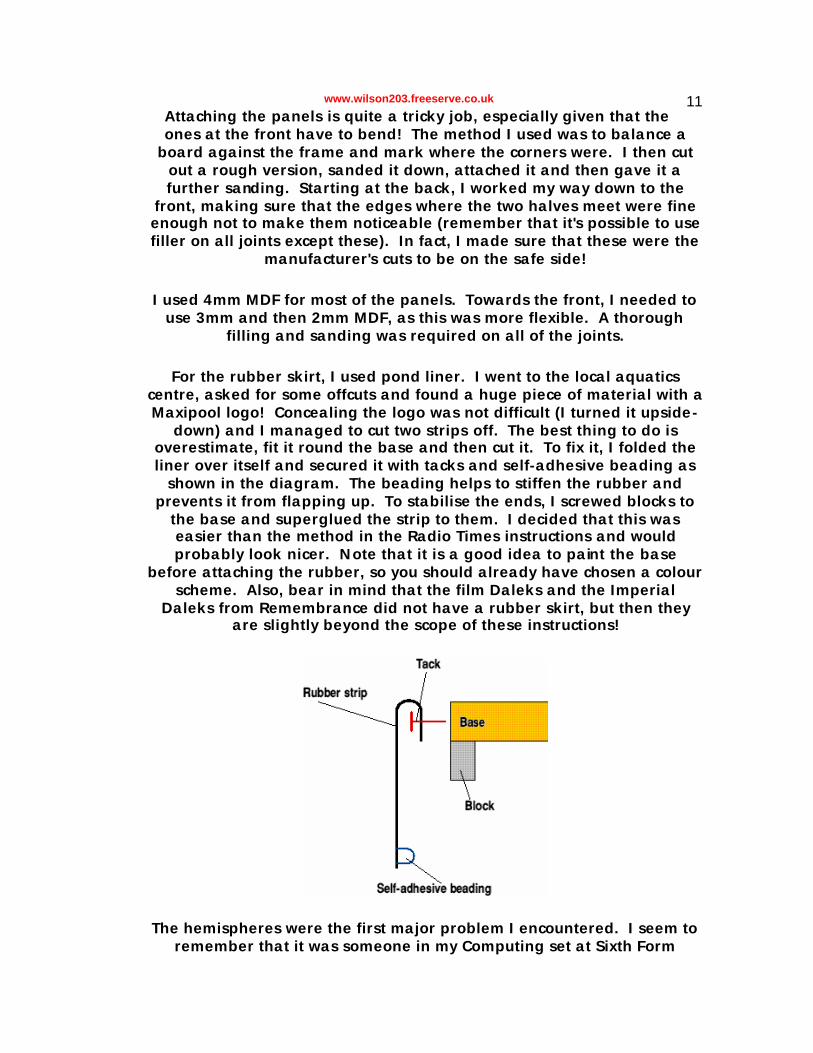
For the rubber skirt, I used pond liner. I went to the local aquatics centre, asked for some offcuts and found a huge piece of material with a Maxipool logo! Concealing the logo was not difficult (I turned it upside-
down) and I managed to cut two strips off. The best thing to do is overestimate, fit it round the base and then cut it. To fix it, I folded the liner over itself and secured it with tacks and self-adhesive beading as
shown in the diagram. The beading helps to stiffen the rubber and prevents it from flapping up. To stabilise the ends, I screwed blocks to
the base and superglued the strip to them. I decided that this was easier than the method in the Radio Times instructions and would probably look nicer. Note that it is a good idea to paint the base
before attaching the rubber, so you should already have chosen a colour scheme. Also, bear in mind that the film Daleks and the Imperial
Daleks from Remembrance did not have a rubber skirt, but then they are slightly beyond the scope of these instructions!
The hemispheres were the first major problem I encountered. I seem to
remember that it was someone in my Computing set at Sixth Form

www.wilson203.freeserve.co.uk 12 College who suggested vacuum-forming, so I think he deserves some credit. Fortunately, my personal tutor happened to be head of Design
and Technology and therefore in charge of the vacuum former. However, there was still the problem of a template, which was half-
solved by buying a polystyrene hemisphere. Despite a nice coating of washing up liquid, it got stuck in the shell and was completely destroyed
when I removed it. I then came up with the idea of making a plaster cast, which also got stuck in the shell! As a result, I decided to press the
plaster-filled hemisphere into some play-doh and make a couple of plaster casts from that. These produced more shells, which in turn
produced two more plaster casts. Theoretically, I could now make 4 hemispheres at a time. However, the vacuum-former wasn't large
enough and I ended up doing 3 at a time, with the fourth plaster cast cooling down nearby. Meanwhile, the plaster cast had come out of the original hemisphere so I would really have been better off using that! The original shell was eventually used to make the eye, as this was of
much higher quality than the rest!
To put it briefly, the simplest thing to do is to find a 4" diameter polystyrene ball, cut it in half and make a hemispherical shell from that. Having scraped out the polystyrene, fill the shell with plaster of Paris.
The cast can be removed by using a screw-in picture hook as a corkscrew. It is a good idea to have at least 3 plaster casts so you can
mass-produce. However, the number of hemispheres you can make at a time depends on the size of your vac-former! This (untested) method
should be much less hassle than the one I used and does not require you to fork out on play doh!
Next came the question of how to attach the hemispheres to the panels. First, I decided to fill the hemispheres with expanding filler foam. This
should be done before removing them from the sheet, otherwise it tends to bend them. Also, it is a good idea to spray the inside with primer to
make the foam stick better. To attach them, put a wall plug in the centre (I made a guide to find the exact centre) and seal it in with more
filler foam. By putting screws in the panels at regular intervals, it is easy to attach them. Also, if any hemispheres break or become dented, they are easy to replace. The best method for determining where each

www.wilson203.freeserve.co.uk 13 hemisphere is to go is to draw a line from the midpoint of the bottom of the panel to the midpoint of the top, measure the length and mark
intervals every fifth of the way along. For the large panels at the back and the sides, treat them as a pair of panels and make the midpoints a
quarter of the way from either end. It makes sense to paint the hemispheres before attaching, especially if you are using car spray
paints.
That completes the skirt, and you can now use it to do Davros impressions while you build the rest!
2. The Shoulders
As with the skirt, this is best considered as three layers- the frame, the
shell and the bands with optional mesh and slats.
The frame
The frame for this section is a lot more fun than the one for the skirt (in a masochistic way!) because of its awkward design. Several little tweaks of mine are visible here. The most obvious is the cut-out section in the
front support so that the box-like assembly to hold the arms can be made as a single piece. Also, you will notice more blocks. This is
because I had to make the base it in two halves, but this time they are fixed together. There are other blocks dotted around to hold dowels, as this is how I made the sections fit together. You may have noticed holes
drilled in the top of this section and the base- these are to hold the dowels from the neck section. The hook on the front support is designed
to hold the cord for the eye, allowing the operator to let go of without the eye-stalk falling down. The dark thing on one of the joining blocks

www.wilson203.freeserve.co.uk 14 is a 9V battery, which I scrapped in favour of a 12V sealed lead-acid
battery.
The base is the hardest part to make. The best thing to do is to print the shape onto A0 paper and use that as a template. However, that is
not possible for most people, so I chose the second-best thing and printed bits of the pattern onto A4, which I then tiled and used as a
template. The top is considerably easier, being a 22" diameter disc. I have not included diagrams, as the bottom is available in a separate file and I assume that everyone knows what a 22" diameter disc looks
like! The base is made from 9mm MDF and the top from 3mm.
The supporting struts are similar to those in the skirt. However, the front one has a section cut out to allow the arm-holder to fit in. I used 15mm MDF for these. Countersunk woodscrews are ideal for assembly, but I didn't find any large enough to go through the base. As a result, I
drilled holes in the skirt to prevent them from fouling.
The shell
This bit will probably reduce people to hysterics. Even at 2mm thickness, MDF isn't the easiest stuff to wrap round a frame. Therefore, I decided to soak two large pieces in the bath! This made them easier to bend
and I held them in place with nails. I made the joins at the side struts as these are less conspicuous than the front (the back and sides will be covered by bands and probably the mesh and slats as well). I trimmed the excess off with strong scissors! More conventional people may wish
to use aluminium or even thin plywood.
The next stage was to fit the arm holder. To mark out the holes, I extended the lines on the diagram until they met the edges. This way, I could mark out the ends of the lines on the shell, using the supporting
struts as a 2D representation and projecting the lines from there. Cutting the holes is best done with a knife. It is then possible to feed the three pieces which make the arm holder through the holes and fix
them to the front strut with screws. The front part also needs four bolts which hold it to the shell. The side pieces can be fitted from inside,
using glue and blocks to hold them to the other three. The holes in the front part for the arms should be sanded so that there is a gradient on the inside to make the balls for the arms fit more neatly. To prevent scraping, I glued very thin pieces of felt to the rims of the holes. This
may sound hard to camouflage, but when painted, the visible parts of the felt become sandable! Finally, the back pieces should be held in
place with sets of 4 bolts and wing nuts.

www.wilson203.freeserve.co.uk 15
The bands
Again, I wish to praise the flexibility of MDF! This time, I did not need to soak it, as I was only using thing strips. However, this is a very tricky
stage!
At the back, the bands are 4" wide with a 3" gap between them (and another 3" gap above). At the front, they narrow to 2" to make space
for the arms. My method of extrapolation worked wonders again, and I was able to work out where the bands jumped from 4" to 2". Before
fitting the bands, spacing blocks should be placed at intervals round the shell. This should be where the bolts go through to hold the bands in
position. It is also a good idea to mark lines at 4", 7" and 11" from the base (and 2" and 9" at the front) so you can see where the bands should go. You can then make a rough cut as you fit the bands and trim them down afterwards. At the front and back, you need to make small strips about 2" wide to join the bands. These should be held in place with pop rivets. There are several ways of doing this, and I used 1 in each corner (which was common throughout the 70s). I suggest looking at photos of whichever type of Dalek you want to build so you can judge for yourself. If you are using aluminium, an idea from the Radio Times instructions is
to fold the strips over the top and bottom. However, in the world of MDF, I just made them 2 inches wide and just slightly higher than the
bands.
If you are making a Dalek from one of the first two stories, you can stop here. However, all the other Daleks had a solar panel array, featuring
wire mesh and vertical strips held in place with pop rivets. The first thing to do is to drill 21 equally spaced pairs of holes round the top
band. Putting pop rivets into MDF is not easy, so you may need to glue washers to the inner surface of the band, otherwise it will be impossible to do a good job. The strips themselves consist of 15 2"x8" and 6 2"x4" rectangles. Wire mesh should be easy to find at any car maintenance shop. I chose a brand called David's, which comes in very conveniently
sized pieces (8"x6"). Before you go off to find a piece which will wrap all the way round the shoulders section, bear in mind that the vertical strips
will hide any joins. As with the skirt panels, I started at the back and worked my way forwards, marking the midpoint of the first piece of mesh, sticking two holes in it and sandwiching it between band and
vertical strip. Now, skip the positions adjacent to it and repeat on the next ones along. With a bit of luck, you should now have 3 vertical strips
with 2 gaps where the mesh overlaps. Fit the 2 vertical strips to these positions, having trimmed away any excess mesh so that there is only a small overlap. Continue this skipping method until you get to the front,
where the overlapping becomes slightly tricky because both vertical

www.wilson203.freeserve.co.uk 16 strips have to have the midpoint of a piece of mesh underneath. This means that you have to fix the mesh to one side, overlapping it with a half-size piece the other side. The extending bits can then be joined in
the normal way. When the mesh narrows towards the front, the slope is just the line from the corner of one strip to the other.
Some of the Daleks from the 70s onwards had an oval disc in the middle of the shoulders section but I do not have the details for this. If anyone
has any suitable measurements, please send them!
Finally, there are the limbs. The instructions for the gun from the Radio Times special are very accurate, but not ideal unless you are good at
brazing. Therefore, I decided to adapt them for the thermally disadvantaged, and have come up with a slightly improved version!
First, you need a piece of 27mm diameter tubing. Length is really up to
you, as it is sensible to have enough of a length inside to act as a handle but making it too long will make it foul against the inside of the arm holder. Next, you need to cut 2 rings from a plastic tube from the
centre of a fax roll. If you do not own a fax machine, then I suggest asking someone who does. You need to drill 8 equally-spaced holes
round the rings (it's very tricky!) and place the first one at one end of the tube. I found that superglue works brilliantly for this. The second ring goes 10" down the tube and should be positioned so that the holes are in line with those in the first ring. Next, take 8 pieces of 12" brass rod
and bend an inch at both ends to 90°. Unless something has gone hideously wrong, these should fit into the holes in the two rings. Again, superglue is ideal for this. However, balance is extremely tricky when
drying, so I suggest using masking tape to hold the rods in place. Also, only do one rod at a time. The Daleks from the Hartnell era had
hexagonal pieces of metal in the gun assembly, but I don't have the details for these. Again, I am open to suggestions!
For a typical 70s firing mechanism, you need a wooden dowel longer enough than the gun itself for you to be able to push it in and out. To this, you need to fix 4 pieces of brass shim and a brass rod. The shim
can be attached with a combination of glue and insulating tape, having been curled first to make it pop out. To fix the rod, I just hammered it
into the dowel until the required length was visible.
To finish, you need a 3½" diameter wooden ball to hold the gun. Unfortunately, I coudn't find any suitable balls so I ended up using ball
floats for a toilet cistern! These are too large, but it is unlikely that anyone will notice the difference. Just drill a suitably sized hole in
either end of the cistern and slide the tube through. Finally, slide the firing mechanism into place.
www.wilson203.freeserve.co.uk 17
The plunger arm is slightly more awkward because there are 3 diameters of tubing and stopping them from rattling is very hard! First, you need a piece of diameter aluminium tubing. Any other metal would
probably do just as well, but plastic is out of the question for reasons which will become obvious. In my Dalek, this piece is fixed in position with the medium-sized piece being movable. You may wish to reverse this for some reason, but I am assuming that you do not. The length of this piece doesn't really matter and I leave it up to you to decide how
much you want to expose. It could be anything from (fully extended) to 0" (fully retracted). However, the former will make it very hard to move
the Dalek around without knocking things over and the latter really defeats the point of the inner tube!
To attach the plunger, I suggest hammering a wooden block into the
end of the tube. Next, find a sink plunger of the type where the rubber is held to the handle by a screw. I decided to turn my plunger inside out, but whether this looks better or not is a matter of opinion and
depends slightly on your choice of plunger. To attach, simply screw it into the wooden block.
The medium tube should be about " long and in diameter. You can use
either plastic or aluminium, but the plastic tubing in My dalek is inclined to sag. The smaller tube is too narrow to be glued in directly, but I found that by wrapping pieces of cloth round it and gluing them in
place, it could be made to fit perfectly.
Finally, you need a piece of diameter tubing (I used plastic). The length exposed should be " so add this to the diameter of the ball you are using. This can be inserted into a ball in a similar way to the gun,
except that I chose not to make the tube go all the way through in this case. If you are using a hollow ball, you can make the front hole in diameter and the back hole . This way, you can control the arm just
using the extending bit, which also tends to make it less rattly. However, this method means that the length of tubing exposed will be
slightly longer than desired. This is not a problem, as any excess can be removed with a hacksaw. The only way of fixing the tube to a hollow
ball which I found actually worked was to drill a couple of extra holes in the back (remember that these won't be visible) and squirt expanding
filler foam through them. The two pieces have to be held together, otherwise the filler foam will push them apart as it expands. If you are
using solid balls, I imagine that ordianry glue should hold them in place.
To prevent the medium-sized tube from rattling inside the large one,
you need spacers. I found that a fax roll wrapped in cloth decreases this

www.wilson203.freeserve.co.uk 18 slightly when glued about halfway down the tube. Something which I
considered was foam pipe insulation, but I had to abandon that because I could not find any which was the right diameter. Eventually, I found a plastic cap from a container which I think is some sort of test-
tube. I cut a hole in it and used cloth to build it up to the right diameter. This can be fitted in front of the fax roll, which prevents it from becoming unstuck. If you can find something similar, try it! Again, this is a rather troublesome area, so I would be grateful for any advice about possible
spacing methods!
Attaching the limbs is not a difficult task. First, put 8 very long bolts through the holes in the arm holder and hold them in place with nuts.
Next, insert the limbs themselves from behind. It is sensible to remove the firing mechanism from the gun and the inner tubing from the
plunger arm first. Finally, you need two square pieces of wood with an identical pattern of holes to the arm holder. These should slot onto the bolts (unless the bolts are too short!) and they can be held in place by
wing nuts.
3. The neck
Yet another three layered component! There is the familiar concept of a frame, this time wrapped in something black. I chose loudspeaker cloth, but wire mesh would probably be better. Finally, you need 3 rings and 8
rods.
The frame
This is one bit where those Radio Times instructions really got it wrong! The discs at the top and bottom are not the same size. The top one is
19" diameter and the bottom is 20". I went ahead and used their wooden strip idea, taking into account the fact that the strips would not
be vertical. The result was an extremely wonky cage-like structure, which (fortunately) straightened out when I added the rings and rods.
You need to make two discs with the given diameters and notches at 45?
intervals for the strips. The strips can be any width you like (I chose 1cm) and should be " long. Simply glue these into the notches with
something that sets quickly, otherwise you'll be holding the thing for hours! I used a glue gun for this part. Note that the discs should have
holes cut in them to allow access, as the operator's head has to pass through the bottom one and the dome swivel has to be reached through the top one. Finally, the whole thing should be painted black to prevent
anything showing through.
www.wilson203.freeserve.co.uk 19 The grille, rings and rods
The grille can be made from fine wire mesh or loudspeaker cloth. The
purpose of this is to make sure that you can see out but no-one else can see in. One layer of mesh is probably enough, but I found that I needed several layers of loudspeaker cloth. Also, the edges are visible on my
Dalek. Simply wrap the covering round and hold it in place with drawing pins (or tacks) at the top and bottom. A bit of gentle
hammering is required so that the pins go in without the whole structure being demolished.
The rings are made from 27mm MDF. This sounds simple enough until you discover that there is no such thing! As a result, I made my own by sticking together 16mm, 2mm and 9mm layers. The bevel at the corner is 45?, which meant that my angled jigsaw came in handy! The external
diameters of the rings are:
Ring Top Bottom Upper " " Middle " " Lower " "
The internal diameters are about 19.25", 19.5" and 19.75" from top to bottom. Holes are required for the rods, which are 10mm diameter dowels. 8 or these need to be cut, just over " long (note that they
disappear under the dome so the actual length is unimportant). Lower the bottom ring over the neck until it is level with the lower disc. To hold
it in place, you need to use metal plates and screws on the underside. Next, insert the rods and lower the next ring into position. This should
be of the way up the neck. To hold in place, screw through the wooden strips, through the wooden rods and into the ring at each of the 8
intervals, Repeat for the third ring, which is placed of the way up the neck. Note that you should already have painted the rings and rods at
this stage! Also, if you are using wire mesh, it should have been painted as well.
Looking at this section, you could be forgiven for thinking that the neck is the easiest part. However, sanding the rings and neatening up the
gauze is very tricky, as is trying to get the frame to stay together!
The Head
I must warn people that this is the trickiest part. The fibreglass dome was a positive nightmare in my case, and was one of the factors towards the
www.wilson203.freeserve.co.uk 20 end which resulted in the delay and eventual failure of the party I
organised to celebrate completion, but that's another story. The end of the eye stalk also contains the only component I was unable to manufacture for myself. Having said that, I managed to complete it, so don't let me put you
off!
The swivel
Wot, no frame? I suppose the swivel is a frame of sorts. It consists of two discs of 9mm MDF and a 3mm hardboard ring, all 19" in diameter.
The hardboard ring has 6 holes drilled at 60? intervals to hold ball bearings as in the Radio Times instructions. Note that when buying ball bearings, I approached a company who asked how many I required. I decided to get 8 in case any went missing. Well, they sold them by the
bucketful and allowed me to have them free! The hardboard ring is glued to the bottom disc in order to hold the ball bearings, but I don't
recommend putting them in yet!
The swivel itself is a 90? water tank outlet. This enables the cord and wire controlling the eye and lights to be passed through without limiting
the angle of rotation. The two discs require holes about 27mm in diameter to be drilled at the centre. A spacer is required and I cut a 24mm piece off a fax roll and split it with a hacksaw for this purpose.
The top disc requires two wooden strips to hold the nut from the outlet in place. The best way to fit these is to test fit the outlet, nut and spacer
with the two discs and align the strips. Once you are ready to assemble the whole thing, place the ball bearings in the holes carefully ! Place the second ring on top and push the outlet through. The nut should nowbe placed between the wooden strips and the outlet screwed into place.
The swivel now needs several spacing blocks to hold it 50mm above the neck. Using layers of 16mm and 9mm, I was able to build 8 of these up. The finished version shows the dowels inserted into these to prevent the
swivel from slipping off the neck.
The dome
Here we go! For this stage, you need a massive pile of clay. Fortunately, I had made friends with one of the art tutors at my sixth
form college, having done an enhancement course in pottery. Since this was towards the end of the Summer term and all of the exams were
over, there was plenty of clay lying around, so we started building this massive 20" diameter dome! I made a former from MDF, using a cross-section of the dome as a template. This can then be moved round the
dome to shape it.

www.wilson203.freeserve.co.uk 21
When you are satisfied with the dome, make a plaster cast of it. Th method is identical to the one in the instructions, so I won't go into too much detail. Simply make some plaster of paris and build up layers with hessian scrim to reiforce the structure. My mould was about 1cm
thick, and I think it consisted of 3 layers of plaster/scrim.
When you produce the mould, you may notice irregularities on the surface. Let nothing tempt you into sanding the mould! Fill in any pits but remember that any bumps will turn into pits on the finished dome and can be filled in easily. The next stage is to coat the inner surface with shellac. This will provide a smooth layer and make it easier to
remove the dome.
Finally, you get on to the fibreglass! The inner surface of the dome must be painted with release agent (which I gather is similar to car wax polish) and to paint on a layer of gel coat. Once this has dried, mix some resin and paint it on to strips of fibreglass matting to line the
dome. I used finer matting for the outer layers and thicker matting to reinforce inside. Once you are satisfied that you have a strong enough
dome, the time has come to extract it. This is where disaster struck in my case! Since I had sanded the inner surface, the dome stuck in the mould
and I had to chisel it away! However, if all has gone well, the mould should survive intact in case you ever want to make another Dalek or
have a friend who might be interested.
The fibreglass dome can be sanded and filed to remove any bumps and neaten the rim. Gaps can be filled with a substance used for car body repairs. Next, you need to produce a line across the dome, going over the midpoint and draw a second line perpendicular to it to mark the
positions of the eye and the two lights. I used white mini indicator lights for these. Conveniently, these are stored in a rubber housing with holes for screws. Simply drill a hole the size of the protrusion at the base of the light (the measurement escapes me at the moment!) and 3 smaller
ones around it (the best way to mark these out is to test fit the lamp holder and wiggle a pencil throught the screw holes. Also, you need a
slot at the front "x" for the eye swivel.
Decorations
First, the lights. The metal layer of the holder acts as one terminal, so simply attach a wire to it in the manner of your choice and poke it
through the hole at the bottom which is not already being used by the green wire. Once the holders are screwed into place with appropriate
nuts and bolts, the two green wires can be linked together with a paper

www.wilson203.freeserve.co.uk 22 clip and the others with a connecting block. Next, take a length of zip wire and connect one strand to the clip and the other to the block. The
former can be held in place with masking tape.
Now, there is the eye. The swivel is a piece of mm thick MDF, which means gluing layers together again. The form of the swivel varies from story to story, but the best way to start is with a 4" diameter disc. You
may or may not wish to have a flattened surface where the tube enters. If you do, just sand/file/whatever until you have a 2" flat section. Next, you have to drill a hole 27mm diameter at the edge (in the middle of
the flat section if you have chosen this style) so that the tubing can fit in to form the stalk. As you may have guessed, the stalk is 27mm tubing
(as used in the gun) and must be " between the swivel and the end part. Next, you need 5 discs- 1x4", 2x" and 2x". The original Daleks also had discs of diameter. These are made from 6mm MDF and need a 27mm
hole drilled in the middle. Next, we have one of those lovely vac-formed hemispheres again! Fill with filler foam again but drill a 27mm hole in the middle of the curved surface this time. Also, I found that inserting a
short piece of fax roll tube (which has an internal diameter of 27mm) helps to fit it to the stalk. The front half of the eye varies from story to
story. However, I chose the truncated cone shape which is 4" wide at the base, 3 " wide at the top and " high. Also, there is a scooped-out
section of 3mm. This was the only part I was unable to make myself, as it had to be done on a lathe. Alternatively, you could use a hemisphere
with a 3 " wide hole/indentation at the top if you want a completely spherical eye. Next, there is the lens. The best way to produce the
pattern is to print out one of the ones below on high-quality paper and stick it behind a piece of perspex. Finally, slide all the components onto
the tubing and glue in place.
The swivel is fixed in place by drilling a hole through the centre of the swivel and sliding a brass rod through. The rod is held to the inside of the dome with 6 squares of 2mm MDF arranged as shown. To enable
control of the eye, a hook can be attached to the swivel and string attached. However, this is very hard to control just by passing the string
through the right-angled outlet, so it is sensible to put a pulley underneath the eye (and possibly another above the centre of the dome swivel). The string is then fed through the outlet and under the swivel.
Gravity is sufficient to hold the dome on the swivel, but I glued
supporting blocks to the inner surface of the dome which keep it at the right height and also slot between blocks on the surface of the swivel to
keep the two aligned. Once you have finished this, the head is complete!

www.wilson203.freeserve.co.uk 23 Colour schemes
Since no Daleks were the colour of MDF, you will almost certainly wish to paint yours, and it is not all that easy to tell which colours to use or which
colour scheme you are following. Therefore, here is a guide to Dalek colour schemes, complete with recommended paint. Note the deliberate omission
of film Daleks- even if I knew the colour scheme, there is the matter of appropriate beakers for the lights and the funny grabbers and bases. For
the real obsessives, I suppose I would also have to give the offset of the hemispheres on the mis-aligned panels! ;-)
Types of paint
Colour Appropriate paint for task
Dark grey Rover Tempest grey Light blue Ford Blue
Note that I didn't think it was worth spelling out the colours for aluminium and black, as these are standard. Just use your favourites!
Colour schemes
Generic 1960s
The Daleks in the Hartnell/Troughton era all had the same aluminium scheme. Note that you should use the eye pattern without the central
black dot in this case. In the first two stories, note the lack of
Generic 1970s
The Daleks from Day otD to Planet otD and in Genesis otD had a grey colour scheme and the eye pattern with the black dot.
Note that there are several variations on this scheme from Destiny otD onwards involving the colour of the bottom band of the shoulders and
the solar panel array. At this point, none, either or both could be painted black. Personally, I prefer the plain grey. However, the BBC decided otherwise, since Remembrance's renegade Daleks featured
both items in black.

www.wilson203.freeserve.co.uk 24 Death to the Daleks
For this story, it was decided that the grey colour scheme was not quite as impressive so they came up with this! I think the result doesn't quite
match this goal and I can see why they reverted in Genesis.
Imperial Daleks
I am not suggesting that you try one of Remembrance's Imperial Daleks, but the Daleks in Revelation had the same cream/gold colour scheme.
You could build one of the former if you feel daring enough but I'm afraid you're on your own!