how to align the unit - Consolidated Pumps Ltd - Products to Align a Pump.pdf · Check alignment...
13
1 HOW TO ALIGN THE UNIT First check that the pump has not been damaged during trasport. Place the fondation bolts loosely in the holes of the base plate and align the plate by using shims. Check alignment with a spirit level. It is very important that the pump/motor alignment is carried out correctly. Following the procedure below. The values for Ø and S2 can be found in the next table. The value for S1 is 0,0 mm.
Transcript of how to align the unit - Consolidated Pumps Ltd - Products to Align a Pump.pdf · Check alignment...

1
HOW TO ALIGN THE UNIT
First check that the pump has not been damaged during trasport.
Place the fondation bolts loosely in the holes of the base plate
and align the plate by using shims.
Check alignment with a spirit level.
It is very important that the pump/motor alignment is carried out
correctly. Following the procedure below.
The values for Ø and S2 can be found in the next table.
The value for S1 is 0,0 mm.

2
HOW TO ALIGN THE UNIT
The distance between the shaft ends must correspond to the value for S2 stated in the above table. Displace the shaft keys 180°.

3
HOW TO ALIGN THE UNIT
Check the alignment.
Repeat the alignment
check, 90°displaced.

4
HOW TO ALIGN THE UNIT
Tighten the screws holding the pump and motor to the
base plate
Check the alignment.
The tolerance for S1 is
±0,1 mm, go to slide n°10
The picture shows that the pump must be raised
S1

5
HOW TO ALIGN THE UNIT
Cut out the foil
in adequate size
Place the foil where needed

6
HOW TO ALIGN THE UNIT
Retighten the screws Check the alignment
carefully once more

7
HOW TO ALIGN THE UNIT
S2
4mm - std coupling
6mm - with spacer
The air-gap width S2 must correspond
to the value stated on the table.
The tolerance of each of the four
points to be checked is ±0,1 mm

8
HOW TO ALIGN THE UNIT
Tighten the screw in the
coupling half
Fit the coupling guard

9
HOW TO ALIGN THE UNIT
Alignment checks
Initial alignment (cold alignment)
Before grouting of base plate: To ensure alignment can be obtained
After grouting of base plate: To ensure that no charges have occurred during
grouting process
After connection to piping: To ensure that piping strains have not altered alignment.
If changes have occurred, alter piping to remove strains on pump flanges.
Initial alignment (cold alignment)
After first run: To obtain correct alignment when both pump and driver are at
operating temperature. Thereafter alignment should be checked periodically in
accordance with plant operating procedures.
NOTE: Alignment check must be made if process temperature changes, piping
changes or the pump is serviced

10
HOW TO ALIGN THE UNIT
Suction piping
The suction piping should be as direct and short as possible.
If a long suction line is required, the pipe size should be increased to reduce
frictional losses.
Where the pump must lift the liquid from a lower level, the suction piping be laid out
with continual rise toward the pump, avoiding high spots in the line to prevent the
formation of air pockets. Where the static suction head will exist, the suction piping
should slope continuously downward to the pump.
Eccentric reducers with a change in diameter greater than 10 cm (4 in) may disturb
flow. If such a change is necessary, it is advisable to use properly vented concentric
reducers.
Elbows and other fitting next to the pump suction should be carefully arranged; or
the flow into the pump impeller will be disturbed. Long-radius elbows are preferred
for suction lines because they create less friction and provide a more uniform flow
distribution than standard elbows.
Is extremely important to avoid the formation of vortices at the suction of both wet-pit
and dry-pit pump installations

11
HOW TO ALIGN THE UNIT
Discharge piping
Generally both a check valve and a gate valve are installed in the discharge line.
The check valve is place between the pump and the gate valve and protects the
pump from reverse flow in the event of unexpected driver failure or from reverse flow
from another pump.
The gate valve is used when priming the pump or when shutting it down for
inspection and repairs.

12
HOW TO ALIGN THE UNIT
13
HOW TO ALIGN THE UNIT
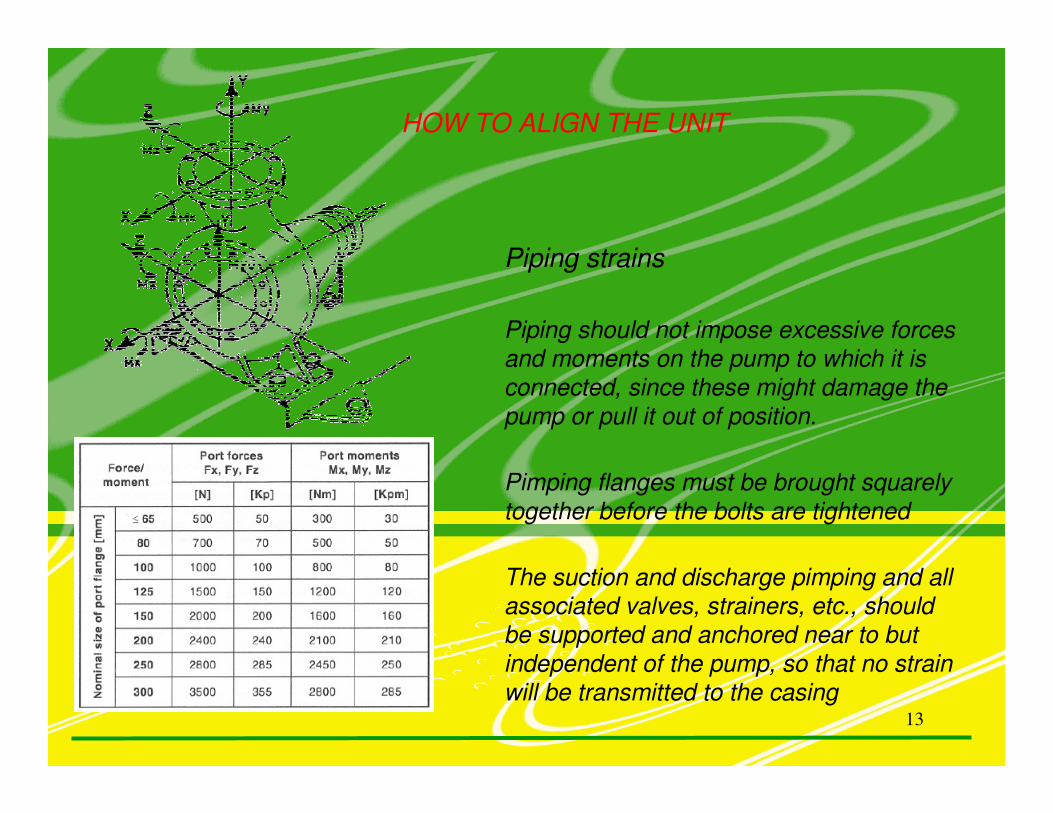
Piping strains
Piping should not impose excessive forces
and moments on the pump to which it is
connected, since these might damage the
pump or pull it out of position.
Pimping flanges must be brought squarely
together before the bolts are tightened
The suction and discharge pimping and all
associated valves, strainers, etc., should
be supported and anchored near to but
independent of the pump, so that no strain
will be transmitted to the casing