HOUSING REPORT Load-bearing wall buildings protected...
13
World Housing Encyclopedia an Encyclopedia of Housing Construction in Seismically Active Areas of the World an initiative of Earthquake Engineering Research Institute (EERI) and International Association for Earthquake Engineering (IAEE) HOUSING REPORT Load-bearing wall buildings protected with the "sliding belt" base isolation system Report # 76 Report Date 05-06-2002 Country KYRGYZSTAN Housing Type Seismic Protection Systems Housing Sub-Type Precast Concrete Building : Large Panel Precast Walls Author(s) Jacob Eisenberg, Svetlana Uranova, Marat Abdibaliev, Ulugbek T. Begaliev Reviewer(s) Svetlana N. Brzev Important This encyclopedia contains information contributed by various earthquake engineering professionals around the world. All opinions, findings, conclusions & recommendations expressed herein are those of the various participants, and do not necessarily reflect the views of the Earthquake Engineering Research Institute, the International Association for Earthquake Engineering, the Engineering Information Foundation, John A. Martin & Associates, Inc. or the participants' organizations. Summary Sliding belt is a base isolation system developed to protect buildings from seismic effects by reducing and limiting the level of seismic forces. The sliding belt system is installed at the base of the building between the foundation and the superstructure. The foundation is usually made
Transcript of HOUSING REPORT Load-bearing wall buildings protected...
World Housing Encyclopedia an Encyclopedia of Housing Construction in
Seismically Active Areas of the World
an initiative of Earthquake Engineering Research Institute (EERI) and
International Association for Earthquake Engineering (IAEE)
HOUSING REPORT Load-bearing wall buildings protected with the
"sliding belt" base isolation system
Report # 76
Report Date 05-06-2002
Country KYRGYZSTAN
Housing Type Seismic Protection Systems
Housing Sub-Type Precast Concrete Building : Large Panel Precast Walls
Author(s) Jacob Eisenberg, Svetlana Uranova, Marat Abdibaliev, Ulugbek T. Begaliev
Reviewer(s) Svetlana N. Brzev
Important This encyclopedia contains information contributed by various earthquake engineering professionalsaround the world. All opinions, findings, conclusions & recommendations expressed herein are those of thevarious participants, and do not necessarily reflect the views of the Earthquake Engineering ResearchInstitute, the International Association for Earthquake Engineering, the Engineering InformationFoundation, John A. Martin & Associates, Inc. or the participants' organizations.
Summary
Sliding belt is a base isolation system developed to protect buildings from seismic effects byreducing and limiting the level of seismic forces. The sliding belt system is installed at the baseof the building between the foundation and the superstructure. The foundation is usually made

of cast-in-situ concrete and the superstructure is typically a load-bearing wall structure, eithera 9-story, large concrete panel system, or a 3-story brick masonry construction. Once theearthquake base shear force exceeds the level of friction force developed in the sliding belt,the building superstructure starts to slide relative to the foundation. The lateral loadtransferred to the superstructure is expected to be approximately equal to the frictional forcethat triggers the sliding of the structure. The sliding belt consists of the following elements: (a)sliding supports, including 2-mm-thick stainless steel plates attached to the foundation and 4-mm Teflon (PTFE) plates attached to the superstructure, (b) reinforced rubber restraints forhorizontal displacements (horizontal stop), and (c) restraints for vertical displacements(uplift). A typical large panel building with plan dimensions 39.6 m x 10.8 m has 63 slidingsupports and 70 horizontal and vertical restraints. The sliding belt scheme was developed inCNIISK Kucherenko (Moscow) around 1975. The first design application in Kyrgyzstan wasmade in 1982. To date, the system has been applied on over 30 buildings in Bishkek,Kyrgyzstan. All these buildings are residential buildings and are presently occupied. Base-isolated buildings of this type have not yet been exposed to the effects of damagingearthquakes.
1. General Information
Buildings of this construction type can be found in Kyrgyzstan. There are about 30 base isolated buildings in Bishkek(Kyrgyzstan). In 1982, two 3-story brick masonry wall buildings were built in the area with high seismicity (9-10 perMSK scale). A residential block (microdistrict) of 9-story concrete large panel buildings protected with seismic isolationbelt was built in the period 1983-1990. Several 9-story large panel concrete buildings were built in the center of Bishkek.One of the buildings is also equipped with a dynamic damper. Some buildings with seismic isolation belt were built in
Kazakhstan and Russia (Kamchatka). This type of housing construction is commonly found in urban areas. Thisconstruction type has been in practice for less than 25 years.
Currently, this type of construction is being built. .
Figure 1A: Typical Building
Figure 1B: Typical Building
Figure 2: Key Load-Bearing Elements
2. Architectural Aspects
2.1 Siting These buildings are typically found in flat terrain. They do not share common walls with adjacent buildings. When
separated from adjacent buildings, the typical distance from a neighboring building is 10 meters.
2.2 Building Configuration Typical shape of a building plan of this housing type is rectangular. Wall openings are same as in typical large panelbuildings. Usually, for a 3.6m long panel, a window size is 1.82 m (width) X 1.53 m (height); for 2.7 m long panel -window size is 1.24 m (width) X 1.53 m (height). The size of a door is 0.9 m (width) X 2 m (height). The size of abalcony door (together with window) is either 2.25 m or 1.66 m (width) or and 1.9 m (height). Overall window and
door areas make up to 20% of the overall wall area. There are 16 windows for a building with 10.8m x 25.2m plan
dimensions.
2.3 Functional Planning The main function of this building typology is multi-family housing. In a typical building of this type, there are no
elevators and 1-2 fire-protected exit staircases. There is one stair in one building unit (with average plan dimensions
10.8 m X 12.6 m).
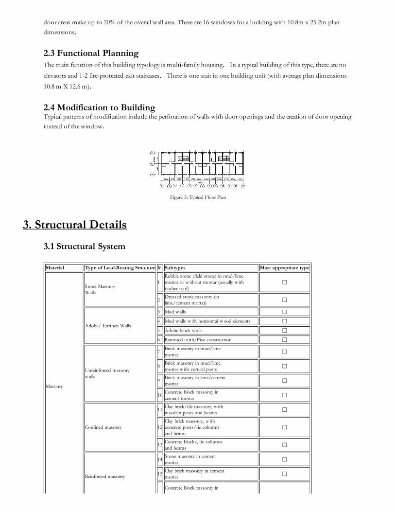
2.4 Modification to Building Typical patterns of modification include the perforation of walls with door openings and the creation of door opening
instead of the window.
Figure 3: Typical Floor Plan
3. Structural Details
3.1 Structural System Material Type of Load-Bearing Structure # Subtypes Most appropriate type
Masonry
Stone Masonry Walls
1Rubble stone (field stone) in mud/lime mortar or w ithout mortar (usually w ith timber roof)
☐
2Dressed stone masonry (inlime/cement mortar)
☐
Adobe/ Earthen Walls
3 Mud w alls ☐
4 Mud w alls w ith horizontal w ood elements ☐
5 Adobe block w alls ☐
6 Rammed earth/Pise construction ☐
Unreinforced masonryw alls
7Brick masonry in mud/limemortar ☐
8Brick masonry in mud/limemortar w ith vertical posts ☐
9Brick masonry in lime/cementmortar ☐
10Concrete block masonry incement mortar
☐
Confined masonry
11Clay brick/tile masonry, w ithw ooden posts and beams ☐
12Clay brick masonry, w ithconcrete posts/tie columnsand beams
☐
13Concrete blocks, tie columnsand beams
☐
Reinforced masonry
14Stone masonry in cementmortar ☐
15Clay brick masonry in cementmortar
☐
Concrete block masonry in

16 cement mortar ☐
Structural concrete
Moment resistingframe
17 Flat slab structure ☐
18Designed for gravity loadsonly, w ith URM infill w alls ☐
19Designed for seismic effects,w ith URM infill w alls ☐
20Designed for seismic effects,w ith structural infill w alls
☐
21Dual system – Frame w ithshear w all ☐
Structural w all
22Moment frame w ith in-situshear w alls
☐
23Moment frame w ith precastshear w alls
☐
Precast concrete
24 Moment frame ☐
25Prestressed moment framew ith shear w alls
☐
26 Large panel precast w alls ☑
27Shear w all structure w ithw alls cast-in-situ ☐
28Shear w all structure w ithprecast w all panel structure
☐
Steel
Moment-resistingframe
29 With brick masonry partitions ☐
30With cast in-situ concretew alls ☐
31 With lightw eight partitions ☐
Braced frame
32Concentric connections in allpanels
☐
33Eccentric connections in afew panels ☐
Structural w all34 Bolted plate ☐
35 Welded plate ☐
TimberLoad-bearing timberframe
36 Thatch ☐
37Walls w ith bamboo/reed meshand post (Wattle and Daub) ☐
38Masonry w ith horizontalbeams/planks at intermediatelevels
☐
39Post and beam frame (nospecial connections) ☐
40Wood frame (w ith specialconnections)
☐
41Stud-w all frame w ithplyw ood/gypsum boardsheathing
☐
42 Wooden panel w alls ☐
OtherSeismic protection systems
43 Building protected w ith base-isolation systems ☐
44Building protected w ithseismic dampers ☐
Hybrid systems 45 other (described below ) ☐
3.2 Gravity Load-Resisting System The vertical load-resisting system is others (described below). Gravity load-bearing structure is a conventionalbuilding construction, either large panel construction or brick masonry construction. Majority of base isolatedbuildings of this type are large panel concrete buildings with monolithic joints (seria 105). This construction type wasdescribed in detail in another contribution from Kyrgyzstan (by S. Uranova and U. Begaliev). Brick masonry buildingsare 3-story high and are equipped with the reinforced concrete members and steel mesh, typical for brick masonry
construction in the former Soviet Union. It should be noted, however, that the construction of conventional 3-storyhigh brick masonry construction was otherwise not permitted in high seismic zones (intensity 9 to 10 on the MSK
scale).
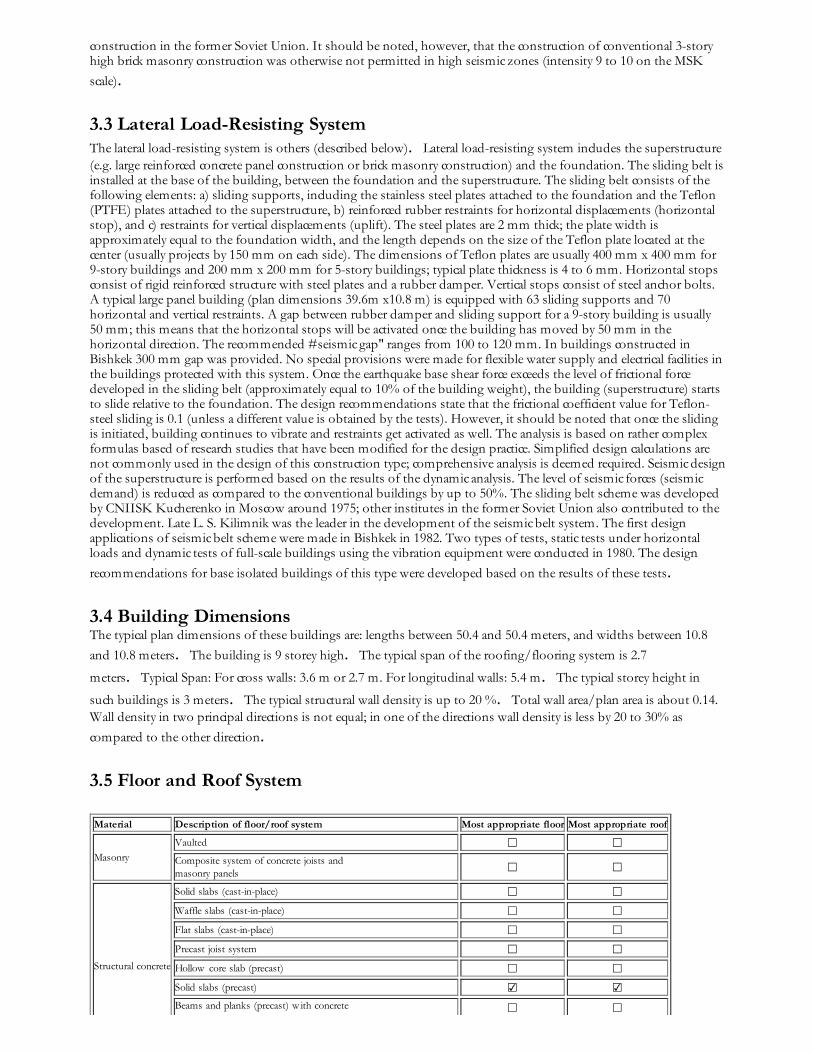
3.3 Lateral Load-Resisting System The lateral load-resisting system is others (described below). Lateral load-resisting system includes the superstructure(e.g. large reinforced concrete panel construction or brick masonry construction) and the foundation. The sliding belt isinstalled at the base of the building, between the foundation and the superstructure. The sliding belt consists of thefollowing elements: a) sliding supports, including the stainless steel plates attached to the foundation and the Teflon(PTFE) plates attached to the superstructure, b) reinforced rubber restraints for horizontal displacements (horizontalstop), and c) restraints for vertical displacements (uplift). The steel plates are 2 mm thick; the plate width isapproximately equal to the foundation width, and the length depends on the size of the Teflon plate located at thecenter (usually projects by 150 mm on each side). The dimensions of Teflon plates are usually 400 mm x 400 mm for9-story buildings and 200 mm x 200 mm for 5-story buildings; typical plate thickness is 4 to 6 mm. Horizontal stopsconsist of rigid reinforced structure with steel plates and a rubber damper. Vertical stops consist of steel anchor bolts.A typical large panel building (plan dimensions 39.6m x10.8 m) is equipped with 63 sliding supports and 70horizontal and vertical restraints. A gap between rubber damper and sliding support for a 9-story building is usually50 mm; this means that the horizontal stops will be activated once the building has moved by 50 mm in thehorizontal direction. The recommended #seismic gap" ranges from 100 to 120 mm. In buildings constructed inBishkek 300 mm gap was provided. No special provisions were made for flexible water supply and electrical facilities inthe buildings protected with this system. Once the earthquake base shear force exceeds the level of frictional forcedeveloped in the sliding belt (approximately equal to 10% of the building weight), the building (superstructure) startsto slide relative to the foundation. The design recommendations state that the frictional coefficient value for Teflon-steel sliding is 0.1 (unless a different value is obtained by the tests). However, it should be noted that once the slidingis initiated, building continues to vibrate and restraints get activated as well. The analysis is based on rather complexformulas based of research studies that have been modified for the design practice. Simplified design calculations arenot commonly used in the design of this construction type; comprehensive analysis is deemed required. Seismic designof the superstructure is performed based on the results of the dynamic analysis. The level of seismic forces (seismicdemand) is reduced as compared to the conventional buildings by up to 50%. The sliding belt scheme was developedby CNIISK Kucherenko in Moscow around 1975; other institutes in the former Soviet Union also contributed to thedevelopment. Late L. S. Kilimnik was the leader in the development of the seismic belt system. The first designapplications of seismic belt scheme were made in Bishkek in 1982. Two types of tests, static tests under horizontalloads and dynamic tests of full-scale buildings using the vibration equipment were conducted in 1980. The design
recommendations for base isolated buildings of this type were developed based on the results of these tests.
3.4 Building Dimensions The typical plan dimensions of these buildings are: lengths between 50.4 and 50.4 meters, and widths between 10.8
and 10.8 meters. The building is 9 storey high. The typical span of the roofing/flooring system is 2.7
meters. Typical Span: For cross walls: 3.6 m or 2.7 m. For longitudinal walls: 5.4 m. The typical storey height in
such buildings is 3 meters. The typical structural wall density is up to 20 %. Total wall area/plan area is about 0.14.Wall density in two principal directions is not equal; in one of the directions wall density is less by 20 to 30% as
compared to the other direction.
3.5 Floor and Roof System
Material Description of floor/roof system Most appropriate floor Most appropriate roof
Masonry
Vaulted ☐ ☐Composite system of concrete joists andmasonry panels
☐ ☐
Structural concrete
Solid slabs (cast-in-place) ☐ ☐
Waffle slabs (cast-in-place) ☐ ☐
Flat slabs (cast-in-place) ☐ ☐
Precast joist system ☐ ☐
Hollow core slab (precast) ☐ ☐
Solid slabs (precast) ☑ ☑Beams and planks (precast) w ith concrete ☐ ☐

topping (cast-in-situ)
Slabs (post-tensioned) ☐ ☐
SteelComposite steel deck w ith concrete slab(cast-in-situ)
☐ ☐
Timber
Rammed earth w ith ballast and concrete orplaster finishing ☐ ☐
Wood planks or beams w ith ballast and concrete or plaster finishing ☐ ☐
Thatched roof supported on w ood purlins ☐ ☐
Wood shingle roof ☐ ☐
Wood planks or beams that support clay tiles ☐ ☐Wood planks or beams supporting naturalstones slates
☐ ☐
Wood planks or beams that support slate,metal, asbestos-cement or plastic corrugatedsheets or tiles
☐ ☐
Wood plank, plyw ood or manufactured w oodpanels on joists supported by beams or w alls
☐ ☐
Other Described below ☑ ☑
3.6 Foundation
Type Description Most appropriate type
Shallow foundation
Wall or column embedded insoil, w ithout footing ☐
Rubble stone, fieldstoneisolated footing
☐
Rubble stone, fieldstone stripfooting ☐
Reinforced-concrete isolatedfooting
☐
Reinforced-concrete stripfooting ☑
Mat foundation ☐
No foundation ☐
Deep foundation
Reinforced-concrete bearingpiles ☐
Reinforced-concrete skinfriction piles
☐
Steel bearing piles ☐
Steel skin friction piles ☐
Wood piles ☐
Cast-in-place concrete piers ☐
Caissons ☐
Other Described below ☐
Foundation include seismo-isolation sliding belt.

Figure 3A: Ground Floor Plan Show ing Locations of Base Isolation
Devices
Figure 4: Critical Structural Details - Base Isolation Devices
4. Socio-Economic Aspects
4.1 Number of Housing Units and Inhabitants Each building typically has 51-100 housing unit(s). 60 units in each building. Typical range from 32 - 64 The number
of inhabitants in a building during the day or business hours is more than 20. The number of inhabitants duringthe evening and night is more than 20.
4.2 Patterns of Occupancy In general, in a building of this type there are 3 - 4 housing units per building unit ("Block-Section"). One familyoccupies one housing unit. Depending on the size of the building (number of stories), 32 to 64 families occupy one
building.
4.3 Economic Level of Inhabitants
Income class Most appropriate type
a) very low -income class (very poor) ☐
b) low -income class (poor) ☑
c) middle-income class ☑
d) high-income class (rich) ☐
50% poor, and 50% middle class inhabitants occupy buildings of this type.
Ratio of housing unit price to annual income Most appropriate type
5:1 or w orse ☐
4:1 ☐
3:1 ☐
1:1 or better ☑

What is a typical source offinancing for buildings of thistype?
Most appropriate type
Ow ner financed ☑
Personal savings ☑Informal netw ork: friends andrelatives ☐
Small lending institutions / micro-finance institutions ☐
Commercial banks/mortgages ☐
Employers ☐
Investment pools ☐
Government-ow ned housing ☑
Combination (explain below ) ☐
other (explain below ) ☐
Until 1990 (the breakdown of the Soviet Union), the financing for buildings of this type had been provided by the
Government. At the present time, all new and existing apartment buildings are privately owned. In each housing
unit, there are no bathroom(s) without toilet(s), no toilet(s) only and 1 bathroom(s) including toilet(s).
4.4 Ownership The type of ownership or occupancy is renting, outright ownership and individual ownership.
Type of ownership oroccupancy?
Most appropriate type
Renting ☑
outright ow nership ☑Ow nership w ith debt (mortgageor other) ☐
Individual ow nership ☑Ow nership by a group or pool ofpersons
☐
Long-term lease ☐
other (explain below ) ☐
These buildings were constructed at the time of the former Soviet Union and the construction was sponsored by the
Government. However, at the present time all apartments are owned by the residents.
5. Seismic Vulnerability
5.1 Structural and Architectural Features Structural/ArchitecturalFeature
StatementMost appropriate type
Yes No N/A
Lateral load path
The structure contains a complete load path for seismicforce effects from any horizontal direction that servesto transfer inertial forces from the building to thefoundation.
☑ ☐ ☐
BuildingConfiguration
The building is regular w ith regards to both the planand the elevation. ☑ ☐ ☐
Roof construction
The roof diaphragm is considered to be rigid and it isexpected that the roof structure w ill maintain itsintegrity, i.e. shape and form, during an earthquake ofintensity expected in this area.
☑ ☐ ☐

Floor construction
The floor diaphragm(s) are considered to be rigid and itis expected that the floor structure(s) w ill maintain itsintegrity during an earthquake of intensity expected inthis area.
☑ ☐ ☐
Foundationperformance
There is no evidence of excessive foundation movement(e.g. settlement) that w ould affect the integrity orperformance of the structure in an earthquake.
☑ ☐ ☐
Wall and framestructures-redundancy
The number of lines of w alls or frames in each principaldirection is greater than or equal to 2. ☑ ☐ ☐
Wall proportions
Height-to-thickness ratio of the shear w alls at each floor level is:
Less than 25 (concrete w alls);
Less than 30 (reinforced masonry w alls);
Less than 13 (unreinforced masonry w alls);
☑ ☐ ☐
Foundation-w allconnection
Vertical load-bearing elements (columns, w alls)are attached to the foundations; concretecolumns and w alls are dow eled into thefoundation.
☑ ☐ ☐
Wall-roofconnections
Exterior w alls are anchored for out-of-plane seismiceffects at each diaphragm level w ith metal anchors orstraps
☑ ☐ ☐
Wall openings
The total w idth of door and w indow openings in a w allis:
For brick masonry construction in cement mortar : lessthan ½ of the distance betw een the adjacent crossw alls;
For adobe masonry, stone masonry and brick masonryin mud mortar: less than 1/3 of the distance betw eenthe adjacent crossw alls;
For precast concrete w all structures: less than 3/4 ofthe length of a perimeter w all.
☑ ☐ ☐
Quality of building materialsQuality of building materials is considered to beadequate per the requirements of national codes andstandards (an estimate).
☐ ☑ ☐
Quality of w orkmanshipQuality of w orkmanship (based on visual inspection offew typical buildings) is considered to be good (perlocal construction standards).
☐ ☑ ☐
MaintenanceBuildings of this type are generally w ell maintained and thereare no visible signs of deterioration of buildingelements (concrete, steel, timber)
☐ ☑ ☐
Additional Comments
5.2 Seismic Features StructuralElement
Seismic Deficiency Earthquake Resilient FeaturesEarthquake DamagePatterns
Wall Application to large panel construction - Panel joints;quality of construction, especially w elding of reinforcingbars from the adjacent panels and filling the gapsbetw een the panels w ith concrete is not satisfactory in
some cases.
Due to a large number and uniform distribution ofpanel joints existing in one building, deficientconstruction of some joints does not have a majorimpact on the overall seismic resistance in thebuilding as a w hole.
Damage of bearingstructures of upper floorsless then in similarbuildings w ithout Seismic
protection system Roof andfloors
is w ithin the panel joints; quality of construction,especially w elding of reinforcing bars from the adjacentpanels and filling the gaps betw een the panels w ith
concrete is not satisfactory in some cases.
include a large number and uniform distribution ofpanel joints existing in one building, deficientconstruction of some joints does not have a majorimpact on the overall seismic resistance in thebuilding as a w hole.
The sliding belt is efficient in reducing the level ofseismic forces in the building
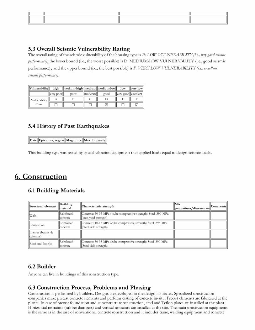
5.3 Overall Seismic Vulnerability Rating The overall rating of the seismic vulnerability of the housing type is E: LOW VULNERABILITY (i.e., very good seismic
performance), the lower bound (i.e., the worst possible) is D: MEDIUM-LOW VULNERABILITY (i.e., good seismic
performance), and the upper bound (i.e., the best possible) is F: VERY LOW VULNERABILITY (i.e., excellent
seismic performance).
Vulnerability high medium-high medium medium-low low very low
very poor poor moderate good very good excellent
VulnerabilityClass
A B C D E F
☐ ☐ ☐ ☑ ☐ ☑
5.4 History of Past Earthquakes Date Epicenter, region Magnitude Max. Intensity
This building type was tested by special vibration equipment that applied loads equal to design seismic loads.
6. Construction
6.1 Building Materials
Structural elementBuildingmaterial
Characteristic strengthMixproportions/dimensions
Comments
WallsReinforcedconcrete
Concrete: 30-35 MPa ( cube compressive strength) Steel: 390 MPa(steel yield strength)
FoundationReinforcedconcrete
Concrete: 10-15 MPa (cube compressive strength) Steel: 295 MPa(Steel yield strength)
Frames (beams &columns)
Roof and floor(s)Reinforcedconcrete
Concrete: 30-35 MPa (cube compressive strength) Steel: 390 MPa(Steel yield strength)
6.2 Builder Anyone can live in buildings of this construction type.
6.3 Construction Process, Problems and Phasing Construction is performed by builders. Designs are developed in the design institutes. Specialized constructioncompanies make precast concrete elements and perform casting of concrete in-situ. Precast elements are fabricated at theplants. In case of precast foundation and superstructure construction, steel and Teflon plates are installed at the plant.Horizontal restraints (rubber dampers) and vertical restraints are installed at the site. The main construction equipmentis the same as in the case of conventional concrete construction and it includes crane, welding equipment and concrete
mixers. The construction of this type of housing takes place in a single phase. Typically, the building is originally
designed for its final constructed size.
6.4 Design and Construction Expertise The expertise required for the design and construction of this type is available. Building designs were prepared bydesign institutes. The academic background of the designers is the same as for conventional construction. It is notrequired to have designers with high academic degrees e.g. M.Sc. and Ph.D. on the team. Construction of base isolatedbuildings and the approval of the designs were controlled by research institutes (State Experts) like any other new
construction performed in accordance with the Building Code requirements. Design of buildings of this constructiontype was done completely by engineers and architects. Researchers also participated in the development of design
documentation. Engineers played a leading role in each stage of construction.
6.5 Building Codes and Standards This construction type is addressed by the codes/standards of the country. SNiP II-7-81. Building in Seismic
Regions.Design code. The year the first code/standard addressing this type of construction issued was 1981. SNiPII-7-81. Building in Seismic Regions. Design code. CNIISK. Recommendations for Design of Buildings with Seismic
Isolation Belt and Dynamic Vibration Dampers, Moscow, 1984. The most recent code/standard addressing this
construction type issued was 1981. Title of the code or standard: SNiP II-7-81. Building in Seismic Regions.Designcode Year the first code/standard addressing this type of construction issued: 1981 National building code, materialcodes and seismic codes/standards: SNiP II-7-81. Building in Seismic Regions. Design code. CNIISK.Recommendations for Design of Buildings with Seismic Isolation Belt and Dynamic Vibration Dampers, Moscow,
1984. When was the most recent code/standard addressing this construction type issued? 1981.
Building permit will be given if the design documents have been approved by the State Experts. State Experts checkthe compliance of design documents with the pertinent Building Codes. According to the building bylaws, buildingcannot be used without the formal approval by a special committee. The committee gives the approval if design
documents are complete and the construction has been carried out in compliance with the Building Codes.
6.6 Building Permits and Development Control Rules This type of construction is an engineered, and authorized as per development control rules. Building permits are
required to build this housing type.
6.7 Building Maintenance Typically, the building of this housing type is maintained by Builder, Owner(s) and Tenant(s).
6.8 Construction Economics For load-bearing structure only (including the seismic belt) the cost is about 230 US$/m². For a similar prefabricatedconcrete panel building (seria 105) without a seismic belt the construction cost would be 50-200 US$/m². Therefore,
the increase in unit cost due to the installation of seismic belt is in the range from 15 to 50 %. It would take from 8
to10 months for a team of 15 workers to construct a load-bearing structure.
7. Insurance
Earthquake insurance for this construction type is typically unavailable. For seismically strengthened existingbuildings or new buildings incorporating seismically resilient features, an insurance premium discount or more
complete coverage is unavailable.
8. Strengthening
8.1 Description of Seismic Strengthening Provisions
8.2 Seismic Strengthening Adopted
Has seismic strengthening described in the above table been performed in design and construction practice, and if so,to what extent?
No. Buildings of this type are already strengthened by means of seismic belt.
Was the work done as a mitigation effort on an undamaged building, or as repair following an earthquake?
N/A.
8.3 Construction and Performance of Seismic Strengthening
Was the construction inspected in the same manner as the new construction?
N/A.
Who performed the construction seismic retrofit measures: a contractor, or owner/user? Was an architect or engineerinvolved?
N/A.
What was the performance of retrofitted buildings of this type in subsequent earthquakes?
N/A.
Reference(s)
1. Recommendations for Design of Buildings with Seismic Isolation Belt and Dynamic Vibration DampersCNIISK, Moscow 1984
2. Seismic Hazard and Buildings Vulnerability in Post-Soviet Central Asia RepublicsKing,S.A., Khalturin,V.I. and Tucker,B.E.
Proceedings of the NATO Advanced Research Workshop on Earthquake Risk Management Strategies for Post-Soviet Central Asian
Republics, Almaty, Kazakhstan, Kluw er Academic Publishers, Dordrecht, Netherlands 1999
3. Building and Construction Design in Seismic Regions-HandbookUranova,S.K., and Imanbekov,S.T.
Kyrgyz NIIP Stroitelstva, Building Ministry Kyrgyz Republic, Bishkek, Kyrgyz Republic (in Russian) 1996
4. Seismoisolation in Russia and former USSR Countries: Recent DevelopmentsEisenberg, J.
Proceedings of the International Post-SMiRt Conference Seminar, Cheju, Korea, Korea Earthquake Engineering Research Center, Seoul, Korea,
Vol.1, p. 99-115 1999
5. Applications of Seismic Isolation in the USSR
Eisenberg, J.
Proceedings of the Tenth World Conference on Earthquake Engineering, Balkema, Rotterdam, Vol.4, p. 2039-2044 1992
6. Operating Experience in Designing and Construction of the System of Special Seismic Isolation of Buildingsand Constructions in the former RussiaEisenberg,J. and Bealiev,V.S.
Proceedings of the Eleventh World Conference on Earthquake Engineering, Pergamon, Elsevier Science Ltd., Oxford, England, Disc 1, Paper
No. 263 1996
7. Experimental Buildings with Seismic Protection in Petropavlovsk-Kamchatskiy (in Russian)
Author(s)1. Jacob Eisenberg
President/Chairman, Russian National Committee for Earthquake Engineer
4 Berezhkovsky Embankment Art 110, Moscow 121059, RUSSIA
Email:[email protected] FAX: 007-095-174-70-64
2. Svetlana Uranova
Head of the Laboratory, KRSU
Kievskai 44, Bishkek 720000, KYRGYZSTAN
Email:[email protected] FAX: 996-3312-282859
3. Marat Abdibaliev
Chairman, Kyrgyzpromproekt
Chuy 219-2, Bishkek 720000, KYRGYZSTAN
Email:[email protected] FAX: 996-3312-215446
4. Ulugbek T. Begaliev
Head of Department, KNIIPC
Vost Prom Zone Cholponatisky 2, Bishkek 720571, KYRGYZSTAN
Email:[email protected]
Reviewer(s)1. Svetlana N. Brzev
InstructorCivil and Structural Engineering Technology, British Columbia Institute of TechnologyBurnaby BC V5G 3H2, CANADAEmail:[email protected] FAX: (604) 432-8973
Save page as