Hotel Indigo 180 Orchard Street New York, NY - … Indigo 180 Orchard Street New York, NY...
132
Hotel Indigo 180 Orchard Street New York, NY Foodservice Equipment Specifications CFL Project # 2137 Issued for Bid July 28th, 2014
Transcript of Hotel Indigo 180 Orchard Street New York, NY - … Indigo 180 Orchard Street New York, NY...

Hotel Indigo
180 Orchard Street New York, NY
Foodservice Equipment
Specifications
CFL Project # 2137
Issued for Bid July 28th, 2014

Table Of Contents Hotel Indigo Clevenger Frable LaVallee, Inc.
DIVISION 11 SECTION 114000
TABLE OF CONTENTS
SECTION 1 INSTRUCTION TO BIDDERS PAGE 1-1 to 1-6 SECTION 2 GENERAL CONDITIONS PAGE 2-1 to 2-10
ARTICLE 1 - CONTRACT DOCUMENTS Page 2-1 ARTICLE 2 - DESIGNER Page 2-1 ARTICLE 3 - OWNER Page 2-2 ARTICLE 4 - FOOD SERVICE EQUIPMENT CONTRACTOR Page 2-3 ARTICLE 5 - SUB CONTRACTORS Page 2-7 ARTICLE 6 - MISCELLANEOUS PROVISIONS Page 2-7 ARTICLE 7 - TIME Page 2-8 ARTICLE 8 - PAYMENTS AND COMPLETION Page 2-8 ARTICLE 9 - INSURANCE Page 2-9 ARTICLE 10 - CHANGES IN THE WORK Page 2-10 ARTICLE 11 - PUBLICITY Page 2-10
SECTION 3 SPECIFIC CONDITIONS PAGE 3-1 to 3-54
PART I - GENERAL Page 3-1 PART II - PRODUCTS Page 3-15 PART III - EXECUTION Page 3-49 PART IV - EQUIPMENT Page 3-54
SECTION 4 BID QUOTATION SUMMARY PAGE 4-1 SECTION 5 EQUIPMENT SPECIFICATIONS PAGE 5-1 to 5-35 SECTION 6 FABRICATION DETAILS PAGE 6-1 to 6-24

Instruction to Bidders Hotel Indigo Clevenger Frable LaVallee, Inc. Page 1 - 1
Project Description This is a NON-UNION labor, or prevailing wage project. The Hotel Indigo is a new construction Hotel located at 180 Orchard Street in NYC. It spans from Orchard Street to Ludlow Street just south of Houston Street. (Yes its right next to Katz’s deli.) There are currently two locations within the Hotel that at this time will be developed. They are, a bulk refrigerated, frozen food storage area, and dry storage areas in the sub-basement, a kitchen and self-serve front of house retail area, both on the 12th floor Lobby, and bars and a storage pantry on the floors above the 12th floor Lobby. The 12th floor kitchen is compact with cooking and prep areas, and an ice machine, J/C closet and ware wash areas as well. The FOH area comprises several grab and go cases offering drinks, dairy, prepared cold foods, beer and wine, baked goods, coffee and espresso, and dry goods. There is also a future bar area on the 12th floor lobby. This will have to be coordinated in the near future. The casework and refrigerated merchandiser in the kitchen are refrigerated by a water-cooled rack system in a service area also on the 12th floor. (See drawing for location.) The bulk cold food storage in the sub-basement is comprised of 2 large food coolers, a large Beer and Wine cooler, both to sit on a tiled floor, and a large Frozen food section They all have remote refrigeration with their locations in the opposite side of the basement. Please note that any questions or requests for information MUST be by E-mail. No phone calls or faxes on this project will be accepted during the bidding process. SEALED Executed Bids shall be addressed and delivered as follows:
1. One Copy To: Clevenger Frable LaVallee 39 Westmoreland Ave. White Plains, N.Y. 10606 Attn: Rick Rasulo Email: [email protected] 1. One Copy To: BCRE – USA
855 Third Ave. 24th Floor New York, N.Y. 10022 Attn: Robert Gormley Email: [email protected]
2. Delivery Time: 5:00 PM August 8, 2014. 3. Method of Delivery: By hand, email, or mail at the responsibility of the Bidder,
enclosed in a sealed envelope, identified by name of Bidder and bearing the following project name:
PROJECT: Hotel Indigo, 180 Orchard St. NYC
B. Preparation and Presentation of Bids
Bid forms have been provided in the Equipment Schedule section for your use. These forms are available electronically in Excel format on the FTP site.
Any bids submitted without the forms provided are to include item number, quantity, Item name, status, unit price and total for each item, with a separate sub-total price for buy-out and fabricated equipment combined, delivery, installation and performance bond. Any and all City, State, occupational and government taxes which are applicable to this installation shall be included and added as a separate charge to this bid. All figures shall be included in a grand total contract price.

Instruction to Bidders Hotel Indigo Clevenger Frable LaVallee, Inc. Page 1 - 2
Your firm name must be typed on each Equipment Schedule and Bid Quotation Summary form in the space provided for this.
Bid is to state any deviation or exceptions to any item and to acknowledge any addenda or change orders. Submit, as part of bid, a list of sub contractors.
C. Performance and Payment Bond
Bidders are required to show the total cost to Owner of the bonds. These costs are to be shown as a separate figure. The cost of the bonds will be deleted from the total price if the Owner waives his right to ask Food Service Equipment Contractor to furnish the bonds.
D. Commencement and Completion of Work
The following project schedule is being provided to indicate completion dates for the order, delivery and timely installation of all food service equipment. Actual dates for delivery and installation may vary slightly depending upon the progress and completion of work to be performed by the Construction Manager/General Contractor. If no revisions are made the project schedule during the course of the project, the installation shall be provided in accordance with the dates outlined below or as coordinated between the Construction Manager / General Contractor to meet the project completion date. This project must be completed on or before the Project Completion Dates indicated. TENTATIVE PROJECT SCHEDULE: Bid Invitation Date ......................................................................................................... July 28, 2014 Bid Due Date .............................................................................................................. August 8, 2014 Award of Contract.................................................................................................... August 18, 2014 Receipt of Ist Issue Shop & Rough-in Drawings ...................................................... August 29, 2014 All Shop Drawings Revised and Approved .......................................................... September 5, 2014 Start of Installation (Hoods and Walk-ins) ................................................................................... TBD Heavy Equipment Installation (Ranges, Fabrication) .................................................................. TBD Millwork and Small Equipment Installation .................................................................................. TBD Start-up & Commissioning/First Punch list .................................................................................. TBD Demo/Second Punch list ............................................................................................................. TBD Total Completion of Project/Opening .......................................................................................... TBD (All contract requirements and punch lists satisfied) The project completion shown above is offered to the bidder for their reference and assistance in determining the scope of the project. Exact installation dates are to be coordinated between the Kitchen Equipment Contractor and the Owner’s Construction Manager/General Contractor or their authorized representative. If no schedule has been provided, refer to the Construction Manager or Owner’s Representative for this information.
E. Drawings
The drawings, which constitute a part of the contract, indicate the arrangement and location of equipment. Should it be necessary to deviate from this arrangement in order to meet field conditions, such deviation shall be made without expense to the Owner.
The data given herein on the drawings is reasonably exact, but extreme accuracy is not guaranteed. Drawings are for the assistance and guidance of the Bidder and exact locations, distances and levels will be governed by the building. The Bidder shall accept the contract with this understanding.

Instruction to Bidders Hotel Indigo Clevenger Frable LaVallee, Inc. Page 1 - 3
The following list of drawings as prepared by Clevenger Frable LaVallee, Inc. shall be considered as part of the bidding documents and shall bear an issue date of July 28, 2014, KA-1 thru KA-5, KB-1 thru KB-4, KC-1 thru KC-4, Marked “Issued For Bid.”
F. Review of Contract Documents
It is the responsibility of the Bidder to carefully review the Contract Documents and shall at once upon discovery during preparation of bid, report to Designer any errors, ambiguities, inconsistencies or omissions at which time Designer will issue an addendum to all Bidders. Unless expressly stipulated, and in a timely manner, no additional allowances will be made for Contractors, or Manufacturers, for errors, omissions or ambiguities not reported at time of bidding.
G. Consultants Drawings
Consultant Drawings are not intended for construction purposes, but are information intended only for use by the Architect and Engineers as an aid in the design of the building and utility distribution systems and for bidding equipment purchased. Consultant drawings in electronic format will not be issued by the Architect or Owner to third parties, including equipment suppliers, without express written consent of the consultant. Consultant base Equipment Plans and Equipment Elevations Sheets will be provided to the contracted equipment supplier in electronic format on request without charge. Utility rough-in/connections schedules and plans will not be provided in electronic form. Regardless of drawing formats provided it will remain the responsibility of the equipment supplier to develop submittals in accordance with the Specific Conditions and assume all required responsibilities thereto. The Consultant is not to be liable for errors and omissions resulting from KEC’s use of electronic data provided by the Consultant.
H. Conflicts in Documentation
In the event of any conflicts between the Instruction to Bidders, General and/or Specific Conditions contained herein and those provided by the Owner/Architect, the Owner/Architect documents shall prevail.
I. Alternates
If the Bidder so desires he may submit, as an alternate, brands and models of equipment other than those specified. Alternates shall be quoted on a separate form attached to the primary bid.
Alternates must be equal in all respects to the base equipment specified. Bids for such alternates must state the manufacturer, model number and include illustrations, specifications, capacities and operational data at the time of the bid. All fabricated equipment shall be by one manufacturer acceptable to the Owner and Designer. If the methods specified and detailed are not in accordance with the Kitchen Equipment Contractor's methods, he may quote, as an alternate, using his methods and standards. The alternate shall include an itemization of all differences.
If alternates require different building conditions, electrical, plumbing, ventilation, etc., from those specified, a complete list of those changes for each item shall be included with the alternate bid. If no changes are required a statement to that effect shall be included. The costs for such changes requested after the bid due date shall be the responsibility of the Food Service Equipment Contractor. Pricing for alternates shall list separately the changes in the price of installation and related items.

Instruction to Bidders Hotel Indigo Clevenger Frable LaVallee, Inc. Page 1 - 4
Alternates submitted after the bid due date will not be considered. Acceptance or rejection of alternates will be at the discretion of the Owner and/or Designer.
Bids will not be considered if they do not include pricing for all base items, even if alternates are included.
The above requirements are waived for alternates requested in the equipment specifications. In any case, it is the Kitchen Equipment Contractor’s responsibility to provide equipment that fits and functions in accordance with the intent of the design. Alternates that impact multiple equipment items are of particular importance. For example, a roll-in combi oven/ streamer is specified to work in conjunction with a roll-in blast chiller and an interchangeable mobile rack. Alternates without an interchangeable mobile rack will not be accepted.
J. Consideration of Bids
The Owner reserves the right to waive irregularities and defects and to reject any and all proposals. The Owner also reserves the right to accept a proposal which is deemed by the Designer to be in the best interest of the Owner.
K. Return of Documents
To receive future consideration, all drawings and specifications issued to Bidders must be returned to Clevenger Frable LaVallee, Inc. upon written request.
L. Questions and Clarifications
If there are questions regarding any aspect of the documents please e-mail your request to the appropriate party. Telephone calls and faxes will not accepted. Bidders will receive a prompt reply by return e-mail. If the reply is relevant to the other bidders it will be issued as an addendum to all bidders. 1. Kitchen Equipment and CLEVENGER FRABLE LAVALLEE Installation: 39 Westmoreland Avenue White Plains, NY 10606 Attn: Rick Rasulo E-Mail: [email protected]
2. Construction Manager: BCRE – USA
855 Third Ave. 24th Floor New York, N.Y. 10022 Attn: Rony Attia Email: [email protected] 646-784-4978
3. Owner’s Representative: BCRE – USA
855 Third Ave. 24th Floor New York, N.Y. 10022 Attn: Rony Attia Email: [email protected]
646-784-4978 M. Terms of Payment
Bidder to propose their terms required for payment. Proposed terms subject to contract negotiations.

Instruction to Bidders Hotel Indigo Clevenger Frable LaVallee, Inc. Page 1 - 5
N. Approved Fabricators
The following is a list of Stainless Steel Custom Fabricators that are approved manufacturers on this project. If the bidder chooses to submit alternate an alternate manufacturer for custom fabricated items, they must include pricing in their base bid provided by the specified manufacturer and submit pricing from one of the alternate manufacturers listed below in accordance with H. Alternates (above).
All State Fabricators Corp (EMI) Cranston, RI (401)-785-3900 (Non-Union) Florida Stainless Fabricators Orlando, FL (407)-971-8280 (Non-Union) Keas Stainless Steel Fabricators Del City, OK (405)-232-0869 (Union) Low Temp Manufacturing Co. Jonesboro, GA (770)-478-8803 (Non-Union) Marlo Manufacturing Boonton, NJ (973)-423-0226 (Non-Union) Pro Stainless, Inc. Keyser, WV (304)-788-5041 (Union) Servco St. Louis, MO (314)-781-3189 (Union) Note: Substitute manufacturers not satisfying the requirements of I. Alternates (above) will be
rejected. O. Approved Food Shield Fabricators
The following is a list of approved manufacturers for the custom fabricated Food Shield s and Food Shields on this project:
Brass Smith Denver, CO. (800)-662-9595 (Non-Union)
Kevry Corporation Golden, CO. (303)-271-9300 (Union) Versa Gard Norcross, GA. (404)-248-9200 (Non-Union) P. Approved Millwork Contractors
The following is a list of Millwork Contractors that are approved as subcontractors on this project. The bidders must include pricing from one (1) of these contractors in their base bid. Pricing from an alternate millwork contractor of the Food Service Equipment Contractor's choice may be shown as a "deduct alternate" on the bid quotation form in the space provided. American Foodservice Savannah, TN (800) 447-4693 (Non-Union)
Interior Creations Inc. Philadelphia, PA (215)-425-9390 (Non-Union) Joe Tagmeyer Hunting Valley, PA (215)-441-5633 (Non-Union) Legere Woodworking Co. Avon, CT (860)-674-0392 (Union)
Regal/Pinnacle Medford, NJ (609)-714-2330 (Non-Union) Q. Site Storage
No provisions shall be made for receipt or storage of any items delivered to the job site before commencement of installation. All items must be received and accounted for by the Food Service Equipment Contractor for delivery and installation as needed according to the project schedule and/or is accepted by owner.
Instruction to Bidders Hotel Indigo Clevenger Frable LaVallee, Inc. Page 1 - 6
R. Site and Field Conditions
See Project Description on Page 1-1 It is the Kitchen Equipment Contractor’s responsibility to assess all site & field conditions and, in particular, those impacting access and delivery of equipment. A visit to the site is recommended
prior to submitting a proposal. In the case of new construction, where a site visit is not possible, a careful review of the architectural drawings is required. Bidders are encouraged to ask questions prior to submitting their proposals. No accommodation will be made for that information contained in the contract documents or that could have been determined by a site visit in advance of submitting a proposal.
S. Errors and Omissions. It is the responsibility of the bidder to report upon discovery during preparation of bid, any errors,
ambiguities and omissions in drawings or specifications, at which time Designer will issue an addendum to all Bidders. Unless expressly stipulated, and in a timely manner, no additional allowances will be made for contractors or manufacturers for errors, omissions or ambiguities not reported at time of bidding.
T. General and Specific Conditions. Bidder shall read carefully the "General Conditions and Specific Conditions" and agrees by
submitting his proposal that these conditions form a part thereof. U. Owner/Vendor Supplied Equipment In submitting their bid the Foodservice Equipment Contractor acknowledges that they will assume
responsibility for coordination of any/all equipment that is indicated on the drawing schedule with a status of “G” - By Owner/Operator and/or status “F” - By Product Suppler/Vendor. Responsibility includes providing cut book cover sheets and data sheets in their cut book submittals, verifying and representing electrical and plumbing requirement on dimensioned rough-in drawings, and responding to general question about installation and hookup as required for equipment with a status of “A” – equipment “In Contract”.
General Conditions Hotel Indigo Clevenger Frable LaVallee, Inc. Page 2 - 1
ARTICLE 1 - CONTRACT DOCUMENTS 1.0 DEFINITIONS 1.1 THE CONTRACT DOCUMENTS A. Contract Documents shall consist of: The Specifications which consist of Instructions to Bidders,
General Conditions, Specific Conditions, Bid Quotation Summary, Itemized Specifications, Fabrication and/or Elevations, CFL Standard Details and the Drawings; all addenda issued prior to the execution of the contract; and all modifications thereto.
1.2 CONTRACT A. The Contract Documents form the Contract. The Contract represents the entire and integrated
agreement between the parties hereto and supersedes all prior negotiations, representations or agreements either written or oral, including the bidding documents.
1.3 THE WORK A. The term work includes all labor, material and services necessary to produce and install the
equipment required by the Contract Documents. 1.4 EXECUTION, CORRELATION AND INTENT A. The Drawings and the Specifications are intended to be complimentary so that any work exhibited
in the drawings is not mentioned in the specifications, or vice-versa, and is to be executed the same as if both mentioned in the specifications and exhibited in the drawings to the true intent and meaning of the said drawings and specifications when taken together. Large scale and full-sized drawings shall be followed in preference to small scale drawings. Figured dimensions shall be followed in preference to scale measurements.
B. Titles and headings to sections in these Contract Documents are introduced for convenience and
shall not be taken as a correct or complete segregation of several units of materials and labor. No responsibility either direct or implied will be assumed by the Owner or the Designer for errors or omissions by the Food Service Equipment Contractor, due to real or alleged error in arrangement or content of matter in the Contract Documents.
C. The drawings and specifications are advisory and for information purposes, only. They are not
intended to be, and shall not be used for construction purposes. They are to be used by licensed Architects and Engineers for preparing their stamped and sealed documents and for the Food Service Equipment Contractor for preparing dimensioned rough-in drawings, brochure submittals and shop drawings.
ARTICLE 2 - DESIGNER 2.0 DEFINITION A. The Designer shall be known as Clevenger Frable LaVallee, Inc., 39 Westmoreland Avenue,
White Plains, NY 10606, and identified as such in the Agreement and is referred to throughout the Contract Documents as if singular in number and masculine in gender. The term Designer means the Designer or his authorized representative.

General Conditions Hotel Indigo Clevenger Frable LaVallee, Inc. Page 2 - 2
2.1 DUTIES AND RESPONSIBILITIES A. Nothing contained in the Contract Documents shall create any contractual relationship between
the Designer and the Food Service Equipment Contractor. B. The Designer will be the Owner's representative during construction and until final payment unless
otherwise specified in the Specific Conditions. Designer will have authority to act on behalf of Owner to the extent provided in the Contract Documents, unless otherwise modified by written instrument that will be shown to Food Service Equipment Contractor. Designer will advise and consult with Owner, and all of Owner's instructions to Food Service Equipment Contractor shall be issued through the Designer.
C. Claims, disputes and other matters in question between Food Service Equipment Contractor and
Owner relating to execution or progress of the work or interpretation of the Contract Documents shall be referred initially to Designer for a decision which he will render in writing within a reasonable period of time.
D. All interpretations and decisions of the Designer shall be consistent with the intent of the Contract
Documents. In his capacity as interpreter and judge, he will exercise his best efforts to insure faithful compliance by both Owner and Food Service Equipment Contractor.
E. Checking rough-in drawings, shop drawings, details and equipment drawings by Designer is for
design concept only, and does not relieve the Food Service Equipment Contractor of responsibility for compliance with design drawings, details and specifications, verification of utilities with equipment requirements for conformity and location, and verification of all dimensions of equipment and building conditions or reasonable adjustments due to deviations.
ARTICLE 3 - OWNER 3.0 DEFINITION A. Owner is the person or organization identified as such in the Agreement and is referred to
throughout the Contract Documents as if singular in number and masculine in gender. The term Owner means the Owner or his authorized representative.
3.1 ACCESS, AUTHORITY AND STOPPAGE A. The work shall be available for inspection at any time by a representative of the Owner. B. All rejected work or material shall be immediately replaced. C. Work may be stopped by Owner if it is not being done in strict accordance with specifications, or
until any objectionable man or material is removed from the premises. The Contract may be declared forfeited for non-performance when not being executed according to the intent and meaning of the contract, drawings and specifications.
D. Such stoppage, suspension or forfeiture shall not in any way invalidate any terms of the contract,
and no extra charge will be allowed the Food Service Equipment Contractor by reason of such stoppage or suspension.

General Conditions Hotel Indigo Clevenger Frable LaVallee, Inc. Page 2 - 3
3.2 WORK UNDER PROTEST A. If the Owner orders certain work done, the Food Service Equipment Contractor shall comply
promptly and fully with such order but in so doing shall not forfeit any right which he may have under this contract to claim extra payments. Any claim which the Food Service Equipment Contractor desires to make regarding work so ordered shall be made to Owner in writing within ten (10) days of receipt of work order.
3.3 OWNER'S RIGHT TO DO WORK A. If Food Service Equipment Contractor should neglect to perform the work properly or any
provision of this contract, the Owner, after three (3) days written notice to the Food Service Equipment Contractor and his surety, may correct deficiencies and deduct the expense from payment due the Food Service Equipment Contractor.
3.4 EMERGENCY REPAIRS A. Owner reserves the right at all times to make emergency repairs without voiding or impairing
guarantee or relieving Food Service Equipment Contractor of responsibility during guarantee period. Any piece of equipment producing objectionable noise must be immediately repaired, removed or replaced.
3.5 SEPARATE CONTRACTS A. Owner reserves the right to let other contracts in connection with this work, and the Food Service
Equipment Contractor shall afford these other contractors reasonable opportunity for the introduction and execution of the work, and shall properly connect and coordinate this work with theirs, as required.
ARTICLE 4 - FOOD SERVICE EQUIPMENT CONTRACTOR 4.0 DEFINITION A. The Food Service Equipment Contractor (FSEC) is the person or organization identified as such
in the Agreement and is referred to throughout the Contract Documents as if singular in number and masculine in gender. The term Food Service Equipment Contractor means the Food Service Equipment Contractor or his authorized representative.
4.1 REVIEW OF CONTRACT DOCUMENTS A. Food Service Equipment Contractor shall carefully compare Contract Documents and shall at
once report to Owner any errors, ambiguities, inconsistencies or omissions he may discover. Unless expressly stipulated, and in a timely manner, Food Service Equipment Contractor shall be liable to Owner or Designer for any damage resulting from any such errors, inconsistencies or omissions in the Contract Documents. Food Service Equipment Contractor shall not do any work without approved Drawings, Specifications and/or Modifications and without receiving prior written authorization from Owner or Designer.

General Conditions Hotel Indigo Clevenger Frable LaVallee, Inc. Page 2 - 4
4.2 SUPERVISION, FABRICATION, INSTALLATION AND PROCEDURES A. Food Service Equipment Contractor shall supervise and direct the work, using his best skill and
attention. He shall be solely responsible for all construction means, methods, techniques and procedures for coordinating all portions of work under the Contract and for coordinating the installation with General Contractor, so as not to interfere with or delay the overall construction of the project.
B. The food service contract documents represent the design intent. It is the Food Service
Equipment Contractor that is responsible for converting the design intent into reality. Relying on their extensive experience and using the highest level of skill available, the Food Service Equipment Contractor and his subcontractors will translate contract drawings, standard details and specifications into finished pieces of equipment that will fit and function as intended, be level, plumb, rigid and true in all respects and satisfy the installation requirements outlined by every foodservice equipment manufacturer represented on the project.
The Food Service Equipment Contractor will exercise a high level of care when translating the contract documents into shop drawings and submittal materials. If the details and specifications provided require enhancement to satisfy the objectives outlined above, then the Food Service Equipment Contractor will work with experts at the manufacturers, fabricators and subcontractors to prepare submittals accordingly so that all equipment delivered is level, plumb, rigid and true in all respects. The point is that we want the full benefit of skill and knowledge from the manufacturer, fabricator and subcontractors reflected in the submittals and in the manufacture and installation of the equipment. What we don’t want and will not accept is the following statement from the Food Service Equipment Contractor when there is a problem with, for example, a swaying table mounted overshelf: “We built it according to the details provided, it’s a design issue”.
C. During the entire installation period, the Food Service Equipment Contractor shall provide a
competent foreman for erection of the equipment regarding connections and installations. The Designer and Owner shall be sole judges as to the competence of the said supervisor.
D. Food Service Equipment Contractor shall provide adequate protection of equipment during
delivery and installation to prevent theft or damage caused by other trades and/or conditions or events that may occur during the construction phase of work. Protection of installed equipment must be provided until the Owner or Owner's representative has taken possession of the equipment installation as specified.
It will be the sole responsibility of the Food Service Equipment Contractor to repair or replace, at
no additional cost to the Owner, any lost or damaged equipment if the written acceptance of equipment by the Owner or Owner's representative has not been secured.
4.3 LABOR, MATERIAL AND TRADE UNIONS A. Unless otherwise specifically noted, Food Service Equipment Contractor shall provide and pay for
all labor, materials, equipment, tools, transportation and other facilities and services necessary for proper execution and completion of the Work. The Food Service Equipment Contractor shall at all times enforce strict discipline and good order among his employees and shall not employ anyone not skilled in the task assigned to him or who will create disharmony on the site.
B. All work to be performed in connection with this contract shall be by workmen of firms whose
employees are not objectionable to the various trade unions in construction of the premises. The Food Service Equipment Contractor shall be wholly responsible for all trade union relations and Owner shall not be liable in any way for delays or claims arising through such causes.

General Conditions Hotel Indigo Clevenger Frable LaVallee, Inc. Page 2 - 5
4.4 WARRANTY
A. All equipment, fixtures and materials furnished and installed shall be guaranteed against defects in workmanship and material; and all repairs and replacements which may have become apparent and necessary by reason of such defects, during the first year after final completion and acceptance of equipment installation, shall be made by the Food Service Equipment Contractor at his own cost and expense without charge to the Owner. All such repairs and replacement shall be made during the first year (except as noted in 4.04 B & E below).
B. For all commercially manufactured equipment that have refrigeration systems, Food Service
Equipment Contractor to furnish additional four (4) year warranty on all compressors. C. Warranty period shall commence with final acceptance of installation by Owner and Construction
Manager. D. Components of equipment subject to replacement prior to one-years use and those items which
may fail due to improper or inadequate periodic maintenance by the Owner/Operator are not intended to be included within the scope of the warranty.
E. Provide two year material and labor warranty on all non-memal countertops. Provide repair of
replacement by reason of any defects except for those caused by operator abuse. D. Components of equipment subject to replacement prior to one-years use and those items which
may fail due to improper or inadequate periodic maintenance by the Owner/Operator are not intended to be included within the scope of the warranty.
4.5 TAXES AND DUTY A. Food Service Equipment Contractor shall pay all duties, sales, consumer, use and other similar
taxes, license and permits as related to his work and required by law. 4.6 PERMITS AND CERTIFICATES A. Food Service Equipment Contractor shall obtain and pay for all necessary permits, inspections
certificates, and licenses required and necessary for performance of the work and post all notices required by law and comply with all laws, ordinances and regulations bearing on conduct of the work as drawn and specified.
B. Procure all necessary certificates of acceptance or completion required and issued by state,
municipal or other authorities and deliver these to Owner. Owner may withhold any payments which may become due to Food Service Equipment Contractor until the necessary certificates are delivered to him.
4.7 SERVICE REPRESENTATIVES A. Provide a competent service representative to be present when installation is put into operation.
He shall lubricate and put into proper operation all equipment and instruct Owner's employees in proper use and maintenance of all items in this contract.

General Conditions Hotel Indigo Clevenger Frable LaVallee, Inc. Page 2 - 6
4.8 SHOP DRAWINGS, PRODUCT DATA AND SAMPLES A. After award of contract and before proceeding with fabrication of any item, the Food Service
Equipment Contractor shall submit for checking, drawings produced by the Food Service Equipment Contractor from verified dimensions and conditions in compliance with requirements of the Specific Conditions. Where field dimensions can not be verified, the Food Service Equipment Contractor shall submit a guaranteed wall dimension plan for approval.
B. After award of contract and before proceeding with the purchase of manufactured equipment, the
Food Service Equipment Contractor shall submit product data in compliance with requirements of the Specific Conditions.
C. Submit samples of materials and parts of work requested by the Designer for adequately judging
character and quality of work. D. The checking of such drawings, product data and samples shall not relieve the Food Service
Equipment Contractor from responsibility of any deviation from the drawings and specifications unless such deviations are approved in writing by the Owner or the Designer.
E. Shop drawings, Product Data and Samples will be reviewed by the designer. 4.9 ACCESS AND USE OF SITE A. No provisions shall be made for receipt or storage of any items delivered to job site before
commencement of installation except as negotiated with the Owner. All items must be received and accounted for by Food Service Equipment Contractor until acceptance by the Owner or his agent.
B. No signs or nameplates of any type shall be allowed to be displayed on any part of this work or on or about the Owner's premises unless authorized in writing by the Owner or Designer.
4.10 CUTTING, FITTING AND PATCHING OF WORK A. Do all cutting and fitting on equipment for other subcontractors to make their work fit, or as Owner
or Designer may direct. Should any repairs be required due to neglect by other contractors, repairs must be approved by Owner or Designer before the work is performed. All extra charges must be approved and all repairs must be noted in writing before work is performed, stipulating price and by whom extra expense shall be paid. In case the Food Service Equipment Contractor does not secure an extra, expense shall be borne by him. No cutting, drilling or altering of any kind shall be done to building by the Food Service Equipment Contractor without first obtaining permission from the Architectural Representation.
B. The Food Service Equipment Contractor shall be responsible for any patching of ceiling, floor or
wall surfaces required by reason of his work and caused by negligence of his employees. Patches of any kind required will be repaired and charged by the Owner/General Contractor to the party causing damage.
4.11 CLEAN-UP A. The Food Service Equipment Contractor shall keep his areas of responsibility clean and free from
debris and shall leave his area in a finished condition. All cartons, crates and surplus material must be cleaned up daily and removed from the site at the Food Service Equipment Contractor's expense. If the Food Service Equipment Contractor is not diligent in the clean up, the Owner reserves the right to clean up his material and back charge his contract.

General Conditions Hotel Indigo Clevenger Frable LaVallee, Inc. Page 2 - 7
4.12 ROYALTIES AND PATENTS A. Food Service Equipment Contractor shall pay all royalties and license fees. B. Food Service Equipment Contractor hereby covenants and agrees to save Owner and Designer
harmless and indemnify the Owner and Designer from payments of any royalties, damages, losses or expenses for suits, materials and methods used in fabrication of this equipment.
4.13 COMMUNICATIONS A. Food Service Equipment Contractor to provide custom fabricators and manufacturers of
engineered systems with the latest documentation (drawings and specifications) and addendums/ bulletins for purposes of submitting proposals for their work. Preliminary exchanges of any information between the Consultant and the custom fabricator and/or the manufacturer of engineered systems prior to contract award is superseded by the final contract documents.
ARTICLE 5 - SUBCONTRACTORS 5.0 DEFINITION A. A subcontractor is a person or organization who has a direct contract with the Food Service
Equipment Contractor to perform any of the work at the site. The term Subcontractor is referred to in the Contract Document as if singular in number and masculine in gender. The term Subcontractor means the Subcontractor or his authorized representative.
5.1 AWARD OF SUBCONTRACTS A. Names and addresses of all Subcontractors shall be furnished to the Owner and Designer, and
selection of subcontractors must be approved by them. If, in their judgment, any fail to perform the work in strict accordance with the drawings and specifications, the Food Service Equipment Contractor, after due notice from Owner or Designer, shall discharge same, but this shall in no way release Food Service Equipment Contractor from his obligations and responsibility under the contract.
5.2 SUB CONTRACTUAL A. Every subcontractor shall be bound by terms and provisions of the Contract Documents as far as
applicable to his work. Nothing contained herein shall create any contractual relation between any Subcontractor and Owner.
B. Food Service Equipment Contractor shall be fully responsible to Owner for acts and omissions of
his subcontractors. ARTICLE 6 - MISCELLANEOUS PROVISIONS 6.0 LAWS AND ORDINANCES A. All work and materials shall comply with all state and federal laws, municipal ordinances,
regulations and directions of inspectors appointed by proper authorities having jurisdiction. In the event any of the conditions of these specifications violate the code for any industry, then such code conditions shall prevail. The Food Service Equipment Contractor shall state in his bid where the code is at variance with these specifications.

General Conditions Hotel Indigo Clevenger Frable LaVallee, Inc. Page 2 - 8
6.1 ASSIGNMENT OF CONTRACT A. The Food Service Equipment Contractor shall not assign this contract or any part hereof without
written consent of Owner. Owner may assign its right hereunder to an assignee or its affiliate subject to such affiliate's assumptions of the Owner's obligations.
6.2 CLAIMS FOR DAMAGES A. Should either party to the contract suffer injury or damage to person or property because of any
act or omission of the other party or any of his employees, agents or other for whose acts he is legally liable, claims shall be made in writing to such other party within a reasonable time after first observance of such injury or damage.
6.3 PERFORMANCE BOND AND LABOR AND MATERIAL A. Owner shall have the right to require the Food Service Equipment Contractor to furnish a
performance and payment bond in a form acceptable to the owner for the amount of the contract, covering faithful performance of the contract and payment of all obligations arising there under.
6.4 TESTS A. If Contract Documents, laws ordinances, rules and regulations or orders of any authority having
jurisdiction require any work to be inspected, tested or approved, the Food Service Equipment Contractor shall give Designer timely notice of it's readiness and of date arranged so Designer may observe such inspection, testing or checking. The Food Service Equipment Contractor shall bear all costs of such inspections, tests and checking’s unless otherwise provided.
ARTICLE 7 - TIME 7.0 PROGRESS AND COMPLETION A. Time is of the essence in this agreement and acceptance constitutes a guarantee that the Food
Service Equipment Contractor can and will obtain all materials, equipment and manpower, upon notice to proceed, to permit overall completion of the entire building project on schedule. The Food Service Equipment Contractor shall coordinate his work with the progress schedule, as prepared and updated periodically by the General Contractor.
ARTICLE 8 - PAYMENTS AND COMPLETION 8.0 CLAIMS FOR PAYMENT A. Claims for payment shall be submitted by the Food Service Equipment Contractor to Owner as
stipulated in the Instructions to Bidders and/or the Owner-Contractor Agreement (Contract). B. The Food Service Equipment Contractor to propose his terms required for payment. Proposed
terms subject to contract negotiations. 8.1 SUBSTANTIAL AND FINAL COMPLETION A. The Food Service Equipment Contractor shall give written notice to Owner that the work is
completed and shall submit evidence satisfactory to Owner in the form of receipted bills for all materials and equipment furnished, waiver of liens from subcontractors and other forms as may be required by the Owner to insure that all payrolls, material bills and other indebtedness connected with the work have been paid.

General Conditions Hotel Indigo Clevenger Frable LaVallee, Inc. Page 2 - 9
8.2 PAYMENTS TO SUBCONTRACTORS
A. The Food Service Equipment Contractor shall pay each subcontractor, upon receipt of payment from Owner, an amount equal to percentage of completion allowed to the Food Service Equipment Contractor on account of such subcontractor's work, less the percentage retained from payment to the Food Service Equipment Contractor. The Food Service Equipment Contractor shall also require each subcontractor to make similar payments to his subcontractors. The Food Service Equipment Contractor shall hold Owner harmless from claims arising out of lawful demands of subcontractors or suppliers. The Food Service Equipment Contractor, at Owner's request, shall furnish proof of payment of obligations to such contractors or suppliers. If the Food Service Equipment Contractor fails to discharge such obligations, the Owner, upon written notice to the Food Service Equipment Contractor, shall withhold an amount from the Food Service Equipment Contractor's payment deemed to be reasonably sufficient to pay any claim.
ARTICLE 9 - INSURANCE
9.0 PUBLIC LIABILITY, CASUALTY AND WORKER'S COMPENSATION INSURANCE
A. Certificates of liability, casualty and Workmen’s' Compensation insurance shall be filed with Owner when required and will be subject to his checking both as to amount and adequacy of their protection.
B. Make all payments in accordance with unemployment, old age and other insurance and social
security of various governments, pursuant to law for that purpose made and provided, whether enacted at the time or prior to execution of contract or during progress of work hereunder, and assume all liability for compliance with requirements thereof.
C. Assume all liability for injuries to or loss of any Owner's property or the property of any other
contractor which may be employed by Owner on said premises, or to any adjoining property or property of any third person which may be caused directly or indirectly by the Food Service Equipment Contractor under this covenant is absolute and is not dependent upon any questions or negligence of his, his subcontractors, or their employees, and failures of Owner or Designer to direct the Food Service Equipment Contractor to take any particular precaution or refrain from doing any particular act will not excuse the Food Service Equipment Contractor in case of such damage.
9.1 FIRE INSURANCE
A. Owner will insure building or other work included in this contract against loss or damage by fire and against loss and damage covered by standard extended coverage insurance endorsements, the amount of insurance at all times at least equal to amount paid on account of work or materials, and plus the value of work or materials furnished or delivered to the job site but not yet paid for by Owner. The policies shall be in the names of the Owner and the Food Service Equipment Contractor, as their interests may appear.
General Conditions Hotel Indigo Clevenger Frable LaVallee, Inc. Page 2 - 10
ARTICLE 10 - CHANGES IN THE WORK 10.0 CHANGES A. No changes shall be made, nor bills for changes, alterations, modifications, deviations and extra
orders be recognized or paid for except upon written order of the Owner. B. No payment of overtime shall be allowed except upon written order of Owner. C. Materials of equal quality and merit of variations in construction methods from those detailed and
specified may be used, but only upon written consent and checking of Designer. ARTICLE 11 - PUBLICITY 11.0 USE OF PUBLICITY A. Any publicity giving reference to this project, whether in the form of press releases, brochures,
photographic coverage or verbal announcement, shall be only with the general or specific permission of the Owner, and in all instances shall give due mention of the Designer
Specific Conditions Hotel Indigo Clevenger Frable LaVallee, Inc Page 3 - 1
PART I - GENERAL 1.01 RELATED DOCUMENTS
A. General provisions of the contract, including General Conditions, Supplementary Conditions and General Documents, other Division I specification Documents and other Division I specification sections apply under this section.
1.02 SCOPE OF WORK
A. Furnish all labor, materials and services necessary for the provision (furnish and install) of food service equipment to achieve the highest level of quality throughout and in strict accordance with the Contract Documents and local codes including that which is reasonably inferred. No extra charge will be allowed for that which the Food Service Equipment Contractor should have been familiar.
B. Supervise and provide required instructions for work to be performed by other contractors in
connection with requirements for all equipment under this section in order to achieve complete and operable equipment and systems to satisfy equipment manufacturers recommendations.
C. Be responsible for the disassembly (if required), removal, storage and protection (at contractor’s
expense), handling and setting in place all of those items designed in the contract documents as existing/relocate, existing/modify, and existing/relocate/modify at the appropriate time.
D. Within the scope of this work the Foodservice Equipment Contractor needs to provide and install any
and all options and/or accessories incidental to the installation of the equipment to allow it to perform its desired function and conform to the manufacturer’s recommendations for the installation.
1.03 RELATED WORK SPECIFIED ELSEWHERE
A. Floors and setting beds, quarry tile and base, masonry pads, walls and finishes, ceilings and related building work: Divisions 3 through 9.
1. Quarry tile floor finish to be etched, if required, prior to setting food service equipment in place.
B. Wall backing to support all wall mounted equipment: Division 5 and/or 9. C. All water, waste, indirect waste piping from sinks and ventilators, steam and gas services to the
equipment including all shut-off valves, plumbing trim, traps, atmospheric vents, etc., and final connections to the equipment except as specified herein: Division 22.
D. All floor sinks and floor drains: Division 22. E. Piping sleeves for refrigeration and drain lines through building floors: Division 22. F. All electric services and components including wiring to and final connections to all equipment except
as specified herein: Division 26. G. Grounding type receptacles for all wall mounted outlets to be used for plug-in equipment: Division 26. H. Make penetrations in building walls as required to accommodate installation of food service equipment
including, among other items, routing of remote refrigeration lines: Division 4, 5 and/or 9. I. Removal of existing food service equipment not scheduled for reuse: Division 2.

Specific Conditions Hotel Indigo Clevenger Frable LaVallee, Inc Page 3 - 2
J. Installation of mechanical gas shut off valve(s) to shut-off gas supply to cooking equipment in the event of a fire: Division 22.
K. All hood or ventilator duct work upstream from the connection position: Division 23. L. Sub-floor, water proofing, floor depressions, and related building work for cold storage rooms:
Divisions 2 through 9. M. Concrete setting bed, 6 Mil Visqueen vapor barrier, slab urethane insulation with adequate R valve
rating , floor and cove base quarry tile with wire mesh and epoxy grout at depressed cold storage rooms: Division 3 through 9.
N. Furnishing and installation of conduit at cold storage rooms in cooperation with the Food Service
Equipment Contractor: Division 26. O. Installation of light fixtures furnished loose at cold storage rooms: Division 26. P. Connection of cold storage room temperature alarm system to the building security system: Division
26. Q. Conduit and connections between cold storage room temperature probes and remote temperature
recording devices: Division 26. R. Furnishing and installation of main power lines to refrigeration systems control panel and wiring for
control/defrost heaters between panel and coils in accordance with factory supplied wiring diagrams and local codes: Division 26.
S. Final connection of the recirculating and city water to refrigeration rack: Division 22. T. Installation of flexible quick disconnects for water connections to counter-top dispensing units provided
“By Owner” and “By Vendor”: Division 22.
U. Furnish and install plugs and Neoprene Cords to Countertop Equipment Provided ”By Owner “ and “By Vendor”.
V. Furnish and install Z-bar support framing for ceiling mounted foodservice equipment units including, but
not limited to, ventilators, condensate hoods, utensil/pot racks, insulated ceiling panels of cold storage rooms, Note: Foodservice Equipment contractor will furnish and install hangers from equipment to framing or other support system.
W. Conduit for beer/ beverage lines from beer system power packs/ soda systems to dispensing locations:
Division 26 – Electrical.
X. Conduit for refrigeration piping through inaccessible areas, such as under slab on grade: Division 26 – Electrical.
1.04 DEFINITIONS
A. Furnish- Supply and deliver to project site, ready for unloading, unpacking, assembly, installation and
similar operations. B. Install (Set In Place)- Operations at project site including actual unloading, unpacking, assembly,
erecting, placing, anchoring, applying, finishing, curing, protecting, cleaning, and similar operations ; ready for final connections by others.
C. Provide- Furnish and install complete, ready for any final connections by others.

Specific Conditions Hotel Indigo Clevenger Frable LaVallee, Inc Page 3 - 3
1.05 OWNER/PURVEYOR FURNISHED EQUIPMENT
A. Utility connections shown on CFL drawings for purveyor furnished equipment are representative of equipment necessary to support the Owner’s requirements. Obtain and coordinate manufacturer, model number and utility requirements and represent utility requirements on dimensioned rough-in plans.
B. Food Service Equipment Contractor to verify requirements and equipment sizes or other characteristics
necessary to represent Owner/Operator items completely on the shop drawing submittals even though they may be listed as “NIC/Not in Contract” in the Equipment Specification sections of this document.
C. Provide flexible disconnects for utility connections (gas, water and steam) to appropriate trades for
Owner/Purveyor provided equipment items as specified. 1.06 MODIFICATIONS TO EXISTING EQUIPMENT
A. Fire Suppression Systems
1. Any modifications necessary to an existing fire suppression system as the result of changes to an exhaust hood or the replacement or rearrangement of equipment to make it comply with local codes are the responsibility of the FSE Contractor.
B. Confirm that options & accessories specified for modifications to existing equipment units scheduled
for reuse are compatible with the manufacturer/model number of the existing units prior to order placement. Notify Consultant accordingly.
1.07 REGULATIONS
A. All work and materials shall be in accordance with the latest rules and/or regulations of agencies/ authorities having jurisdiction. All regulations, including building codes, and other codes applying to this jurisdiction should be followed. In addition all equipment shall comply with the following:
1. National Electric Manufacturer's Association, (N.E.M.A.). 2. Underwriter's Laboratories Inc. (U.L.) must bear label. 3. National Electric code, (N.E.C.). 4. National Sanitation Foundation, (N.S.F.), must bear label. 5. American Society of Mechanical Engineers must carry the (A.S.M.E.) stamp. 6. American Gas Association (A.G.A.).
7. State and Local Health Department Requirements.
8. American with Disabilities Act (ADA) as applicable to this project.
B. The Contract Documents shall govern whenever they require larger sizes or higher standards than are
required by regulations. C. The regulations shall govern whenever the Contract Documents require something which will violate
the regulations. D. When seismic regulations are applicable, all equipment shall be fabricated and installed in accordance
with those regulations. All seismic requirements shall be shown on all submittals. Submit requested information to the agencies and authorities having jurisdiction.

Specific Conditions Hotel Indigo Clevenger Frable LaVallee, Inc Page 3 - 4
E. No extra charge will be paid for furnishing items required by the regulations, but not specified and/or shown on the drawings.
F. Rulings and interpretations of the enforcing agencies shall be considered a part of the regulations. G. The Food Service Equipment Contractor is responsible to maintain the accuracy of equipment
drawings and cut books to reflect as built conditions due to equipment deletions, manufacturer and/or model number changes and unanticipated changes to site conditions. It will be the Food Service Equipment Contractor’s sole responsibility to notify the Health Department having jurisdiction of all revisions until the project is issued its Certificate of Occupancy.
1.08 ALTERNATES
A. Alternates must be equal in all respects to the base equipment specified. Alternate must state the manufacturer, model number and include illustration, specifications, capacities and operational data.
B. All fabricated equipment shall be by one manufacturer acceptable to the Owner and Designer. If the
methods specified and detailed are not in accordance with the Food Service Equipment Contractor's methods, he may quote as an alternate, using his methods and standards. The alternate shall include an itemization of all differences.
C. If alternates require different building conditions, electrical, plumbing, ventilation, etc., from those
specified, a complete list of those changes for each item shall be included. If no changes are required, a statement to that effect shall be included. The costs for such changes requested after the bid due date shall be the responsibility of the Food Service Equipment Contractor.
D. Alternates submitted after the bid due date will not be considered. Acceptance or rejection of
alternates will be at the discretion of the Owner and/or Designer. E. The above requirements are waived for alternates requested in the equipment specifications. If an
alternate is selected, include the alternate and the requirements for the alternate in all submittals. F. When alternates are listed in the item specifications and the primary manufacturer is unable to provide
the item(s) specified (i.e. bankruptcy), the F.S.E. Contractor shall provide the equipment from an alternate manufacturer for the same price as originally proposed in the bid quotation.
1.09 REVIEW OF CONTRACT DOCUMENTS
A. Unless expressly stipulated, and in a timely manner, no additional allowances will be made for Contractors or Manufacturers for errors, omissions or ambiguities not reported at time of bidding.
B. Carefully review and compare the Contract Documents and at once report to Owner and/or Designer
any errors, ambiguities, inconsistencies or omissions. Unless expressly stipulated, and in a timely manner, Food Service Equipment Contractor shall be liable to Owner or Designer for any damage resulting from such errors, inconsistencies or omissions in the Contract Documents. Work shall not be done without approved Drawings, Specifications and/or Modifications and without receiving prior written authorization from Owner or Designer.
C. Where discrepancies are discovered between the drawings and the specifications, regarding quality or
quantity, the higher quality or the greater quantity is to be included in the Bid Proposal.

Specific Conditions Hotel Indigo Clevenger Frable LaVallee, Inc Page 3 - 5
D. Foodservice Equipment Contractors responsible for verifying and coordinating all items provided in this
Section, with the drawings, specifications, manufacturer’s requirements, submittals, actual site conditions, adjacent items and associated (Sub-) Contractors; to assure that there are no discrepancies or conflicts. This is to include, but not limited to, quantities, dimensions, clearances required, direction of operation, door swings, utilities, fabrication details and methods, installation requirements, etc.
E. All accessory items listed in the itemized specifications section are the responsibility of the foodservice equipment contractor. Careful review of these accessories are required as they may not all be provided by detail C-2-3B, Cutting Board w/ Bracket may be listed in the itemized specifications as an accessory to a Jade griddle. This item is not available from Jade. The foodservice equipment contractor will obtain this item from the appropriate source (custom fabricator) to fulfill the specification.
1.10 DRAWINGS
A. The drawings which constitute a part of the contract indicate the arrangement and location of equipment. Should it be necessary to deviate from this arrangement in order to meet structural conditions, such deviation shall be made without expense to Owner.
B. The data given herein on the drawings is reasonably exact but extreme accuracy is not guaranteed.
Drawings are for the assistance and guidance of the Food Service Equipment Contractor and exact locations, distances and levels will be governed by the building. The Food Service Equipment Contractor shall accept his contract with this understanding.
C. The following list of drawings as prepared by Clevenger Frable LaVallee, Inc. shall be considered as a
part of the bidding documents and shall bear an issue date of July 28, 2014, KA-1 thru KA-5, KB-1 thru KB-4, KC-1 thru KC-4, Marked “Issued For Bid.”
1.11 WARRANTY
A. All equipment, fixtures and materials furnished and installed shall be guaranteed against defect in workmanship and material. All repairs and replacements which may have become apparent and necessary by reasons of such defects, during the first year after final completion and acceptance of equipment installation, shall be made without cost and expense to the Owner. All such repairs and replacements shall be made at a time and during hours satisfactory to the Owner.
B. For all commercially manufactured equipment that has a refrigeration system and semi-hermetic
compressors, furnish an additional four (4) year warranty on all compressors. C. Warranty period shall commence with final acceptance of installation by Owner. D. Components of equipment subject to replacement prior to one years use and those items which may
fail due to improper or inadequate periodic maintenance by the Owner/Operator are not intended to be included within the scope of the warranty.
E. Provide all labor, material, refrigerant, and incidental expenses to maintain the temperatures specified
on all refrigeration systems. Systems to be kept in first class working condition for a period of one (1) year from date of acceptance by Owner, or the date systems are put into operation, whichever occurs first, without additional cost to the Owner.
F. Equipment that fails to perform will be removed and replaced with items of equal value at no expense
to the Owner. Work required to replace equipment that has failed to perform will be completed at the convenience of the Owner.
Specific Conditions Hotel Indigo Clevenger Frable LaVallee, Inc Page 3 - 6
1.12 DISCREPANCIES A. Where discrepancies are discovered between the drawings and the specifications, regarding quality or
quantity, the higher quality or the greater quantity is to be included in the Bid Proposal. B. Contractor is responsible for verifying and coordinating all items provided in this Section, with the
drawings, specifications, manufacturer’s requirements, submittals, actual site conditions, adjacent items, and associated (Sub-) Contractors; to assure that there are no discrepancies or conflicts. This is to include, but not be limited to, quantities, dimensions, clearances required, direction of operation, door swings, utilities, fabrication details and methods, installation requirements, etc.
C. Contractor to notify the Architect, in writing, of any discrepancies discovered; and await written
clarification prior to proceeding with the items or areas in question. 1.13 SUBMITTALS
A. Pre-Requisite to Submittals
1. F.S.E. Contractor shall review, and the shop drawings shall be prepared to reflect, the most current set of Architectural floor plans.
B. Submittal Content
1. Complete submission including hard copies of cut books, rough-in drawings and fabrication shop drawings covering all food service equipment items should be submitted as one (1) package for review and approval. Hard copy submittals are preferred. Although electronic copies are allowed we reserve the right to request hard copy submittals on an as needed basis. 2. The Consultant requires only two copies of each submittal. We will return one copy of marked
submittals. 3. Substitutions must be approved in writing by the Architect and/or Owner prior to utilization in this
contract. A copy of the approval must be included with any submittals by the Food Service Equipment Contractor.
4. FSE Contractor’s use of any Design Team’s AutoCad contract drawings for basis of producing their
submittal drawings, is with the following conditions and understanding:
a. FSE Contractor assumes total liability and responsibility for accuracy, and for conformance and verification with the latest Architectural and Engineering drawings, actual filed conditions and all equipment provided.
b. FSE Contractor Sub-Contractors as required. c. Submittals to have FSE Contractor’s title block and information.
C. Quality of Submittals
1. Submittals are to be of high quality, reflecting a high degree of accuracy and consistent with the
specifications and drawings. The Foodservice Equipment Contractor will review shop drawings from specified manufacturers to confirm that their drawings reflect the consultant’s intent prior to submitting these for the Consultant’s review. The drawings will be returned without review if the drawings do not reflect the Consultant’s intent.
2. Drawings are to be submitted at the appropriate scale. Shop drawings submitted that are “not
to scale” (including plots of all PDF files) will be rejected at the FSE Contractor’s expense. 3. Time spent reviewing 3rd submission shop drawings will be charged back to the
foodservice equipment contractor by the Owner at CFL standard hourly rates.

Specific Conditions Hotel Indigo Clevenger Frable LaVallee, Inc Page 3 - 7
D. Submittal Routing
1. The Food Service Equipment Contractor will confirm submittal routing requirements with the General Contractor or Construction Manager.
E. Product Data
1. After award of contract and before proceeding with the purchase of manufactured equipment, submit two (2) bound sets, each sets should be 3 hold punched (No GBC of VELO Binding). The set will consist of:
a. Hard Cover b. Title Sheet c. Index of all items with columns for: Item number, quantity, description and status (fabricated,
manufactured, existing, "Future", by Owner/Operator, by Vendor, by General Contractor, etc.) d. A typewritten lead sheet for each equipment item (including all new, existing, future and by
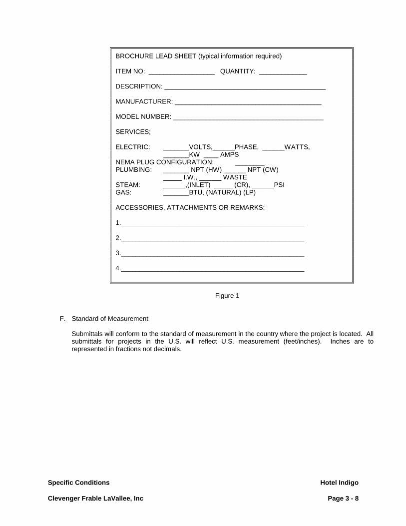
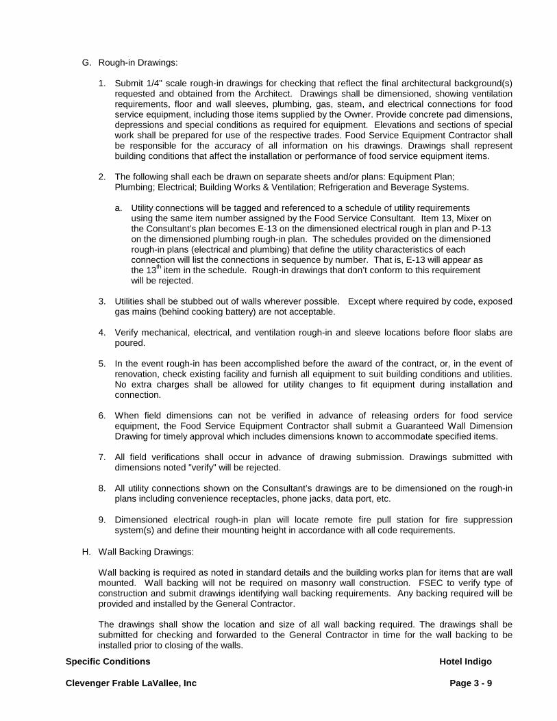
Owner/Operator/Vendor items) showing: Item number; quantity; description; manufacturer's name, address and telephone; model number; optional finishes, equipment, accessories and modifications; utilities required and special notes. (See Figure 1). Incomplete lead sheets will be rejected.
e. Manufacturer's specification sheets and/or drawings.
2. Submittals not in the above format will be returned for resubmittal.
NOTE: FSEC relying on cut book services are not relinquished of any responsibility for reviewing accuracy of submission and fit of equipment.
Specific Conditions Hotel Indigo Clevenger Frable LaVallee, Inc Page 3 - 8
Figure 1
F. Standard of Measurement
Submittals will conform to the standard of measurement in the country where the project is located. All submittals for projects in the U.S. will reflect U.S. measurement (feet/inches). Inches are to represented in fractions not decimals.
BROCHURE LEAD SHEET (typical information required) ITEM NO: __________________ QUANTITY: _____________ DESCRIPTION: ____________________________________________ MANUFACTURER: ________________________________________ MODEL NUMBER: _________________________________________ SERVICES; ELECTRIC: _______VOLTS,______PHASE, ______WATTS,
_______KW ____ AMPS NEMA PLUG CONFIGURATION: ________ PLUMBING: _______ NPT (HW) ______ NPT (CW)
_____ I.W., ______ WASTE STEAM: ______,(INLET) _____ (CR), ______PSI GAS: _______BTU, (NATURAL) (LP) ACCESSORIES, ATTACHMENTS OR REMARKS: 1.__________________________________________________ 2.__________________________________________________ 3.__________________________________________________ 4.__________________________________________________
Specific Conditions Hotel Indigo Clevenger Frable LaVallee, Inc Page 3 - 9
G. Rough-in Drawings:
1. Submit 1/4" scale rough-in drawings for checking that reflect the final architectural background(s) requested and obtained from the Architect. Drawings shall be dimensioned, showing ventilation requirements, floor and wall sleeves, plumbing, gas, steam, and electrical connections for food service equipment, including those items supplied by the Owner. Provide concrete pad dimensions, depressions and special conditions as required for equipment. Elevations and sections of special work shall be prepared for use of the respective trades. Food Service Equipment Contractor shall be responsible for the accuracy of all information on his drawings. Drawings shall represent building conditions that affect the installation or performance of food service equipment items.
2. The following shall each be drawn on separate sheets and/or plans: Equipment Plan; Plumbing; Electrical; Building Works & Ventilation; Refrigeration and Beverage Systems.
a. Utility connections will be tagged and referenced to a schedule of utility requirements using the same item number assigned by the Food Service Consultant. Item 13, Mixer on the Consultant’s plan becomes E-13 on the dimensioned electrical rough in plan and P-13 on the dimensioned plumbing rough-in plan. The schedules provided on the dimensioned rough-in plans (electrical and plumbing) that define the utility characteristics of each connection will list the connections in sequence by number. That is, E-13 will appear as the 13th item in the schedule. Rough-in drawings that don’t conform to this requirement will be rejected.
3. Utilities shall be stubbed out of walls wherever possible. Except where required by code, exposed gas mains (behind cooking battery) are not acceptable.
4. Verify mechanical, electrical, and ventilation rough-in and sleeve locations before floor slabs are
poured. 5. In the event rough-in has been accomplished before the award of the contract, or, in the event of
renovation, check existing facility and furnish all equipment to suit building conditions and utilities. No extra charges shall be allowed for utility changes to fit equipment during installation and connection.
6. When field dimensions can not be verified in advance of releasing orders for food service
equipment, the Food Service Equipment Contractor shall submit a Guaranteed Wall Dimension Drawing for timely approval which includes dimensions known to accommodate specified items.
7. All field verifications shall occur in advance of drawing submission. Drawings submitted with
dimensions noted "verify" will be rejected. 8. All utility connections shown on the Consultant’s drawings are to be dimensioned on the rough-in
plans including convenience receptacles, phone jacks, data port, etc. 9. Dimensioned electrical rough-in plan will locate remote fire pull station for fire suppression
system(s) and define their mounting height in accordance with all code requirements.
H. Wall Backing Drawings: Wall backing is required as noted in standard details and the building works plan for items that are wall
mounted. Wall backing will not be required on masonry wall construction. FSEC to verify type of construction and submit drawings identifying wall backing requirements. Any backing required will be provided and installed by the General Contractor.
The drawings shall show the location and size of all wall backing required. The drawings shall be
submitted for checking and forwarded to the General Contractor in time for the wall backing to be installed prior to closing of the walls.

Specific Conditions Hotel Indigo Clevenger Frable LaVallee, Inc Page 3 - 10
I. Fabricated Shop Drawings: 1. Prepare and submit shop drawings for all special fabricated items included in this contract. The
detail drawings shall be submitted at minimum of 3/4" scale for elevations and 1-1/2" scale for sections and on a minimum sheet size of 24” x 36”. Drawings shall show all dimensions, all details of construction, installation and relation to adjoining and related work. Drawings shall show all reinforcements, anchorage and other related work required for the complete installation of all fixtures.
2. Fabrication details and sections drawings shall be prepared to reflect "worst case" conditions and illustrate close tolerances.
3. Fabricated shop drawings shall be consistent with the bidding documents. Any variances that may
require changes to the building utility systems should be discussed with the Designer prior to submission.
4. Fabrication drawings shall show manufacturer, model number and all equipment items, including
those of other manufacturers, drawn to scale. For example, elevation drawings of exhaust hoods shall show manufacturer, model number and cooking appliances drawn to scale.
5. When custom stainless and or custom millwork counters for cafeteria serving areas are included in
the scope of work, the Foodservice Equipment Contractor is required to provide a complete set of fully coordinated shop drawings representing all equipment and materials provided by multiple manufacturers including millwork or stainless steel counters, stone or composite counter tops and all foodservice equipment items. As part of the shop drawing submittal process, the FSE Contractor will provide a fully coordinated set of custom stainless and / or custom millwork shop drawings reflecting all items “In Contract” and related items “Not In Contract”. Those parties providing any equipment “Not in Contract” will be responsible for submitting product data/ shop drawings for specific items they are providing. The Food Service Equipment Contractor will be responsible for obtaining and reflecting those requirements in the F.S.E. submittal. The drawing set should include a floor plan identifying all units and their relationship to one another, plan details for each item at a scale of ½” = 1’-0”, elevation drawings at ¾” = 1’-0” and sections/detail drawings a 1 ½” = 1-0” identifying:
a. Dimensions and locations of all counter top cut-outs. b. The overall dimension that drop-in equipment units extend below the counter top. c. The exact size and locations of all food shields. Locate all uprights relative to counter and
adjacent equipment units. d. Where counters with cut-outs contain counter top mounted units, identify the size and
location of same. e. The relationship of all items “In Contract” to items “Not in Contract”. f. Cut-outs for remote controls, utility routing, access for drains, ventilation requirements, etc.
g. Details of food shield mounting requirements. h. Details food service equipment installation in stone or composite counter tops, if
applicable, consistent w/ the manufacturer’s recommendations.
6. Where cafeteria service counters (referenced above) or other Millwork assemblies (including, but not limited to bar die & top, back bar, service stations, millwork buffet units, etc.) are not in the F.S.E. Contractor’s scope of work, the F.S.E. Contractor will provide product data on those “in contract” items that relate to the millwork assemblies being provided by Others sufficient to enable Others to prepare shop drawings as outlined in #5 above. Once the shop drawings are prepared by Others they will be submitted to the F.S.E. Contractor for review and coordination.
Fully coordinated shop drawings, satisfying the requirements of #5 above, will then be submitted to the Architect for review and approval.

Specific Conditions Hotel Indigo Clevenger Frable LaVallee, Inc Page 3 - 11
7. Shop drawings submittals are to reflect all standard details specified by the by the Consultant. Consultant approval of shop drawings does not preclude the Foodservice Equipment Contractor from providing the details specified.
8. For self-contained refrigeration systems located within cabinet body construction, confirm the
recommended free area of ventilation with the manufacturer and coordinate the location of the ventilation louvers with the custom fabricator.
J. Refrigeration Drawings:
1. Manufacturer's drawings and manufacturer's specification sheets shall be submitted for approval
prior to commencing work. Drawings shall include refrigeration piping showing actual line sizes and system allocation, evaporators, compressors, condensers, and required valves and accessories.
2. Specification sheets and drawings shall be presented in bound sets with all items and piping
properly identified, including model, system allocation, any required electrical characteristics and BTU load as applicable.
K Exhaust Hood Drawings: 1. Shop drawings submitted for exhaust hoods are to reflect exhaust/ make-up air data
represented on the “plans and specifications” including identical duct collar quantities, size and location, cfm requirements and static pressure. Drawings submitted for approved substitutions or drawings from alternate manufacturers listed as “equal” in the item specification of this document are not excluded from this requirement. Duct and fan systems will not be re-engineered to conform to shop drawings showing different exhaust/ make-up air data than those specified. Drawings submitted that don’t reflect “plans and specifications” will be rejected.
L. Solid Surface Materials Shop Drawings
1. Only Approved Certified Fabricator/Installers as listed by the Solid Surface Material Manufacturer
will be accepted. 2. The Food Service Equipment Contractor must provide drawings detailing the fabrication and
installation methods of the food service equipment in the solid surface material.
M. Incomplete/Inaccurate Submittals
1. Submittals that do not satisfy the requirements noted above will be returned for re-submittal at the expense of the Food Service Equipment Contractor.
N. Checking:
1. Checking product data, rough-in drawings, wall backing drawings, shop drawings, and refrigeration
drawings by Designer is for design concept only, and does not relieve the Food Service Equipment Contractor of responsibility for compliance with Contract Documents, verification of utilities with equipment requirements for conformity and location, verification of all dimensions of equipment and building conditions or reasonable adjustments due to deviations.
2. Drawings shall be prepared on the Food Service Equipment Contractor's sheets and by his
employees. In those cases where the Food Service Equipment Contractor relies on electronic files provided by the Consultant at the request of the Owner, the Food Service Equipment Contractor is reminded of the importance of the shop drawing phase. The availability of electronic files for purposes of expediting the submittal process is not intended to short-cut the thought process required to achieve a complete and accurate submittal.

Specific Conditions Hotel Indigo Clevenger Frable LaVallee, Inc Page 3 - 12
3. Submittals and checking shall be accomplished before ordering equipment or starting fabrication.
O. Mailing and Distribution:
1. After checking, distribute cutbooks and drawings (up to ten sets) as directed by the Owner.
P. Response to Inspection List: 1. FSEC shall respond to the inspection list prepared by the Consultant within five (5) working days
from receipt by either initiating corrective action to the items noted or by submitting a written report addressing the disputed items.
1.14 SCHEDULE
A. Time is of the essence and acceptance constitutes assurance the FSE Contractor can and will obtain
materials, equipment and manpower, to permit installation of the items included in this section, on schedule. FSE Contractor is to coordinate their work with the progress schedule, as prepared and updated periodically by the General Contractor or Construction Manager.
B. Anticipated delays, not within the control of the Contractor, are to be noted in a written notification to the Architect, immediately upon the Contractor’s realization that delays are imminent.
C. Failure of the manufacturers to meet promised delivery dates will not grant relief to the Contractor for
failure to meet schedules, unless the Contractor can establish, in writing, that orders were received by the manufacturer, with reasonable lead times.
D. Extra charges resulting from extra handling or air shipment in order to meet the schedule will be paid by the Contractor, if insufficient time was allowed in placing factory orders.
1.15 PARTS AND SERVICE MANUALS
A. Furnish two (2) bound sets of parts and service manuals.
1. The manuals shall include a source directory for parts and service for all items. 2. The manuals shall be submitted in time to allow review and transmittal to the Owner/Operator prior
to start-up and demonstration of the equipment. Manuals must be submitted before the Owner will issue final acceptance of the installation.
B. Furnish “As - Built “ plans of foodservice areas. Note that all submittals must be revised through the course of completing the project to reflect all as built conditions.
1.16 VERIFICATION AND COORDINATION OF PROJECT/DATA
A. Range Lines: All front manifold range lines shall be assembled and aligned at the factory before shipment, including
back guards, high shelves and salamanders.

Specific Conditions Hotel Indigo Clevenger Frable LaVallee, Inc Page 3 - 13
B. Pans and Inserts Verify sizes directly w/ the Owner/ Operator on the following representative items before ordering
equipment relating to these items:
1. Steam Pans 3. Trays* 5. Plate Sizes 2. Sheet Pans 4. Glass and Cup Racks 6. Cup Sizes
Include verification of tray orientation and spacing at locations of soiled tray return areas, tray make-up areas, etc.
C. Color selections “By Architect” upon contract award submit a listing of those items requiring “color
selection by Architect” directly to the architect along with information from the manufacturer including color charts, detailing the choices available.
D. Quietness of Operation Quietness of operation of all food service and refrigeration equipment is a requirement. Remove or
repair any equipment producing objectionable noise. E. Delivery and Entry Verify all conditions at the building prior to submitting your proposal
. In particular, verify door openings, passageways, elevator sizes, etc. to avoid delivering items too large for entry. Where items of equipment specified are too large to fit into the building in one piece and there is no alternative but to manufacture the items of equipment in multiple pieces and assemble them on site, the additional cost of these changes is to be reflected in the Foodservice Equipment Contractor’s proposal.
Coordinate with the General Contractor necessary access to insure delivery of equipment to the required areas. Coordination shall include, but not be limited to, early delivery, hoisting, window removal and/or delay of wall construction. The costs of manufacturing foodservice equipment in multiple pieces, field work necessary to assemble equipment made up of multiple units, handling charges, window removal, etc. shall be borne by the Food Service Equipment Contractor.
F. Connection Terminals
All equipment will be complete with standard connections as they relate to their Country of Origin. It
shall be the responsibility of the Food Service Equipment Contractor to provide any and all required adaptors to assure the proper connection to the conditions at the job site.
G. Site Verification Notify Designer, Owner and the General Contractor in writing if, in the Food Service Equipment
Contractor's opinion the job site is not adequate to insure proper installation of the equipment. Notification shall be in writing with sufficient time to effect corrective measures to meet the installation schedule.
H. Cold Storage Rooms and Refrigeration Systems
1. Coordinate the timely installation of the wearing floors inside the cold storage rooms with the
General Contractor to prevent prolonged exposure of the floor insulation. 2. Confirm that the cold storage rooms are not used by any other trade for storage or work areas.
Repair or replace any damaged areas of the cold storage rooms, if the damage was caused due to the cold storage rooms being used for storage or work areas.

Specific Conditions Hotel Indigo Clevenger Frable LaVallee, Inc Page 3 - 14
3. Be responsible for determining the acceptability of the location of the remote refrigeration condensing units in regard to ambient temperature, noise and accessibility. If the condensing unit location is determined to be unacceptable for any reason, advise Owner and request direction in writing.
I. Millwork Coordination
1. Coordinate with the Millwork Contractor by providing the following information to the Millwork Contractor prior to the preparation of their millwork shop drawings:
a. Provide equipment sizing information for all foodservice equipment relating to millwork items. b. Provide cut-out dimensions for all equipment units that drop-in or are built into the counter
tops, counter aprons, etc.
c. Identify dimensions/clearances required between heated drop-in units and adjacent cabinet body millwork.
d. Carefully coordinate the locations of controls for ease of employee access.
e. For self-contained refrigeration systems located within the millwork cabinet body confirm the
recommended free area of ventilation with the manufacturer and coordinate the location of the ventilation louver(s) with the Millwork Contractor.
f. Ship units of equipment that impact dimensions & construction of millwork to millwork
contractor.
g. Refer to 1.11, H. 5 and 6 for additional requirements. J. Site Utility Coordination a. Confirm utilities available on site including Natural or LP gas, Direct Steam, etc. prior to releasing orders for equipment.

Specific Conditions Hotel Indigo Clevenger Frable LaVallee, Inc Page 3 - 15
PART II - PRODUCTS 2.01 COMMERCIALLY MANUFACTURED EQUIPMENT
A. All items of standard equipment shall be the latest model at time of delivery. B. Manufacturer's directions shall be followed in cases where the manufacturers of articles used in this
contract furnish directions or prints covering points not shown on the drawings or specifications. C. All doors shall be hinged as shown on plans. D. Refrigerated Items
1. All reach-in refrigerators and freezers with remote refrigeration systems shall be complete with condensate evaporator when no floor drain is available.
2. When a condensate evaporator is required, it shall be complete with thermostatic expansion valves
at the evaporator. 3. Refrigerated drawer units are to be provided with stainless steel drawer liners and stainless steel
full size pans. Food Service Equipment Contractor to furnish each drawer with two (2) 12" x 20" x 4" deep 18 ga. stainless steel pans.
4. When a removable plate rail/cutting board is specified for an equipment stand, the Food Service
Equipment Contractor is to coordinate cutting board support locations with work top cooking appliances to provide access for operations and service.
5. The refrigerant for medium and low temperature fixtures to be CFC free and conform to the
Montreal Protocol Agreement. 6. All refrigerated fixtures are to be provided with a flush mounted exterior dial thermometer. 7. All refrigeration Systems to be provided with 5 year compressor warranty and 1 year service agreement. 8. Doors on refrigerated fixtures are to be provided with cylinder door locks unless specified with a
alternate locking devise. 9. All glass panels provided as part of refrigerated display cases are to be made of insulated glass.
E. Free-standing work tables and counters with flanged feet shall be secured to the floor with smooth head stainless steel fasteners or with pins concealed in all legs of the table/counter, when specified or required by code.
F. All equipment units that "pass thru" wall openings are to have an "equal" finish on front and rear. The
intent is that the equipment unit will project a finished "look" on the rear (kitchen side) as on the front (customer side).

Specific Conditions Hotel Indigo Clevenger Frable LaVallee, Inc Page 3 - 16
G. Provide water treatment units/systems (including surge tanks) for installation by the Plumbing Division suited to the application and anticipated volume for items “in contract” and those units provided “by vendor”, “by product supplier” or “by owner” as follows: Postmix beverages: Low to medium volume = Everpure Coldrink Twin-MC² p/n EV9328-02 High volume = Everpure Coldrink Triple-MC² p/n EV9328-03 Coffee: Low to medium volume = Everpure E-10 EV9795-80 and QL3-BH² EV9272-00 High volume = Everpure E-20 EV9795-90 and QC71 Twin Head EV9272-22 with MH² cartridges EV9613-21 Ice makers: Less than 650#/day = Insurice Single PF-i2000² EV9324-21 Less than 1200 lbs/day (or Hoshizaki between 300-450 lbs/day) Insurice Twin PF-i2000² EV9324-22 Less than 1600 lbs/day (or Hoshizaki between 500-1250 lbs/day) Insurice Triple PF-i4000² EV9325-23 Less than 2400 lbs/day (or Hoshizaki between 1300-2200 lbs/day) E-20 EV9795-90 and Insurice Quad-i4000² EV9325-04
Combination: Less then 3.33gpm High Flow CSR Twin EV9330-42 Less then 5gpm High Flow CSR Triple EV9328-06 Less then 6.67gpm High Flow CSR Quad EV9437-10 Higher volume use High Flow CSR Plus EV9347-20 Steam (boiler only): Countertop and floor steamers less the 1.67 gpm Kleensteam CT-EV9797-50 Flow rates less the 2.5gpm Kleensteam II Single EV9797-21 Flow rates less the 5gpm Kleensteam II Twin EV9797-22
Provide wall mounted rack per detail C-19-4 when surge tank is wall mounted. Provide suitable sized dunnage rack for floor mounted surge tank. Provide three sets of filters for the system provided, that’s one set for the system to operate & two sets of filters for back-up/replacement.

Specific Conditions Hotel Indigo Clevenger Frable LaVallee, Inc Page 3 - 17
H. Food Service Equipment Flexible Connectors
1. Gas Cooking Equipment Connections: FSE Contractor shall furnish gas cooking appliances with appropriately sized (length, diameter and BTU capacity) Dormont Safety System gas connector assemblies. a. Gas appliances (movable and non- anchored stationary)
Dormont Series 16xxKITCF2S inclusive of: Gas connector, 2 Swivel Max Swivels, coiled restraining cable and hardware, and SafetyQuik combination valve/quick disconnect.
b. Gas appliances ( Floor anchored Stationary )- Dormont Series 16xxBP connector. All gas connection devices shall be CSA and NSF compliant.
2. Appliances requiring water supply
a. Counter top Equipment FSE Contractor shall supply countertop coffee brewing and dispensing equipment with Dormont SwirlHose retractable connectors including 2-way water quick disconnect. Sizing in diameter and length shall be sufficient to GPM requirements of appliance and length to the water source. NSF Approved. This includes equipment “in contract”, and those items “by vendor”, “by product supplier” or “by owner”.
b. Cooking equipment with water supply required- FSE Contractor shall supply Dormont Series WxxBP2Q connectors inclusive of the connector and a 2 way water quick disconnect on all movable and non anchored equipment requiring a water feed. (Cold or Hot) Size shall be determined based on GPM requirements and proximity to water source. Wheeled (castered) equipment will require appropriately sized coiled restraining device. Dormont series: RDC.
c. Cooking appliances with steam supply required- FSE shall supply Dormont Series HxxBIP2Q connectors inclusive of the connector and a 2 way quick disconnect on all movable and non anchored equipment requiring a steam feed. Connector steam source. Wheeled (castered) equipment will require appropriately sized coiled restraining device. Dormont series: RDC
3. Remote Refrigeration, Mobile Units. When specified, FSE Contractor shall provide and make final connection to remote refrigerated fixtures with flexible pull-out assemblies for refrigerant from Packless Industries. Units fabricated of red brass tubing with continuous helical corrugation covered by bronze braid. Standard models have an SAE male flare at one end and an SAE female flair swivel of the same size at the other end. U.L. and C.S.A. approved. Provide pull-out assemblies of diameter, length (custom, if required) and connector type as recommended by the manufacturer for each application.
4. Positioning Devices
When required by Authority having jurisdiction, mobile (wheeled) cooking equipment shall be held in position utilizing the Dormont Safety-Set device. Dormont : part # PS.
5. Division 23 to connect all quick-disconnect hoses for water and gas to equipment.
I. Fire Suppression Systems
a. Fire suppression systems will be installed to conform with all applicable codes. b. All piping to surface protection nozzles to be chrome plated. c. Remote fire pull stations to be recessed in building wall. d. Minimize elbows on piping to surface protection nozzles. e. Coordinate placement of protection nozzles to avoid conflict cooking equipment and
accessories (range faucets). f. All piping drops to surface protection nozzles to be aligned in the same plane.
J. Buy Out Equipment

Specific Conditions Hotel Indigo Clevenger Frable LaVallee, Inc Page 3 - 18
The following is a list of standards for all “buy out” equipment: 1. The intent is that exposed metal surfaces of buy-out equipment units have a
Stainless steel finish except where the model number of the unit dictates aluminum. For those items where stainless fronts, tops, rears and sides are “optional” we expect that a stainless finish will be provided in those areas where the finish is exposed.
2. All range units if not provided with a rear riser as a standard component by the manufacturer are to be provided with a stub back (min.).
3. Provide any/all stacking/mounting kits as may be required per the manufacturers recommendations
for stacking equipment units together (for example: ice makers positioned on top of soda/ice dispensers), built-in/drop-in units into custom fabricated fixtures, etc.
4. Accessories may be required that are not available from the manufacturer of the specified
equipment. The Food Service Equipment Contractor shall provide those accessories as separate items. As an example, a Jade JGT- 2436 griddle may be specified with a cutting board and support bracket per detail C-2-3B. This support bracket specified is not available from Jade. It needs to be custom fabricated. The cost of the cutting board and support bracket needs to be included in the price of the griddle in the Food Service Equipment Contractor’s proposal to the Owner. A thorough review of all accessories specified is necessary to properly account for their cost and avoid schedule delays
2.02 PLUMBING WORK
A. Provide suitable pipe slots, chases and/or do all drilling, punching and cutting of equipment required to provide access for Division 22 connections and/or runs. Such work performed at the job site shall be of the same quality as similar work in the shop.
B. To insure proper clearance for cleaning, all horizontal piping lines shall be run at the highest possible
elevation and not less than 6" (150 mm) above floor, through equipment wherever possible. C. Indirect waste piping (except from sinks and ventilators) shall be installed in accordance with the codes
in effect at the job site. Piping shall run as described hereinafter, and shall discharge into floor sinks. Extend piping to a point of at least 2" (50 mm) above rim of floor sink and cut bottom on 45 degree angle. All indirect waste piping shall be installed and routed in a manner to insure proper drainage and shall conform with shelves, spaces, equipment or building conditions. Secure all indirect waste piping as required to achieve same.
1. Indirect waste piping from ice bins, ice pans and similar items shall be insulated to prevent
condensation.
D. Water inlets shall be located above the positive water level to prevent siphoning of liquids into the water system. Wherever conditions shall require a submerged inlet, a suitable type of check valve and vacuum breaker shall be placed on the fixture to form part of same to prevent siphoning.
E. Where exposed, piping and fittings shall be chrome plated. F. All valves shall be American made to insure availability of replacement parts.

Specific Conditions Hotel Indigo Clevenger Frable LaVallee, Inc Page 3 - 19
G. FAUCETS
1. Faucets shall be furnished on all sinks, bain maries, water stations and other fixtures as specified and shall be supplied with non- splash aerator, and water saving devices where required by local codes. Unless otherwise specified, faucets shall be provided as follows, for installation by Division 22: (Note: All faucets to be from the same manufacture).
Type 1: Faucet (1/2 Splash)
Fisher Model 3251 (8” Spout)* T&S Model B—0231 with #60 x (8” Spout)
Type 2: Faucet (3/4 Splash)
Fisher Model 30376 (14” Spout) T&S Model B-0290 (12” Spout)
Type 3: Faucet (1/2 Deck)
Fisher Model 3311 (8” Spout)* T&S Model B-1121 (8” Spout)
Type 4: Faucet (3/4 Deck)
Fisher Model 5314 (14” Spout) T&S Model B-0293 (12” Spout
Type 5: Faucet (1/2 Deck)
Fisher Model 1821 (Gooseneck)* T&S Model B-1142 (Gooseneck)
Type 5A: Faucet (1/2 Splash) Fisher Model 1945 (Gooseneck)*
T&S Model B-0331 (Gooseneck)
Type 5B: Faucet (1/2 Deck) Fisher Model 3525
Type 6: Faucet (1/2 Deck)
Fisher Model 3010 (INDEX HOT) T&S Model B-207 (INDEX-HOT)
Type 7: Pre-Rinse Faucet (1/2 Splash)
Fisher Model 2210-WB T&S Model B-0133B W/Wall Bracket
Type 7A: Pre-Rinse Faucet (1/2 Deck)
Fisher Model 2310-WB T&S Model B-0113 W/Wall Bracket
Type 8: Fill Faucet (1/2 Wall) Double Jointed Swing Sprout
Chicago Model 515 (INDEX COLD) T&S Model B-592
Type 9: Dipperwell & Faucet
Fisher Model 3041 Component Hardware Model K27-1010
Type 10: Water Fill Faucet & Drain Pan
Fisher Model 1400 Component Hardware Model K27-1000
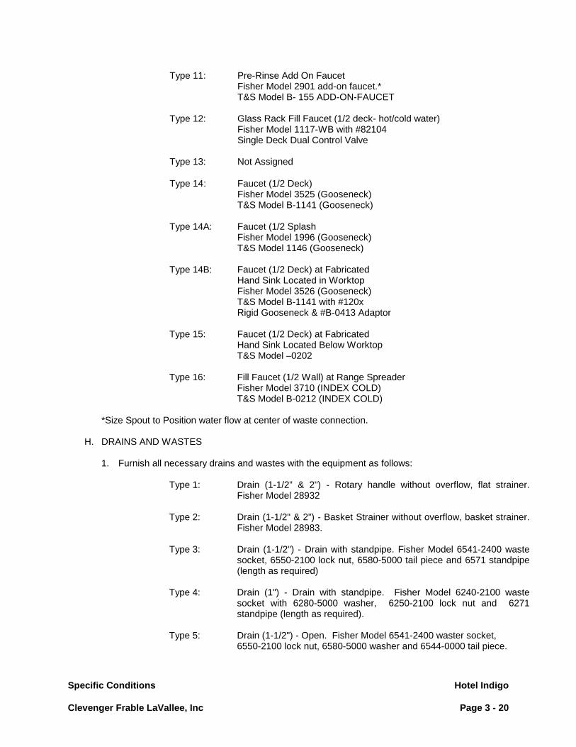
Specific Conditions Hotel Indigo Clevenger Frable LaVallee, Inc Page 3 - 20
Type 11: Pre-Rinse Add On Faucet
Fisher Model 2901 add-on faucet.* T&S Model B- 155 ADD-ON-FAUCET
Type 12: Glass Rack Fill Faucet (1/2 deck- hot/cold water)
Fisher Model 1117-WB with #82104 Single Deck Dual Control Valve
Type 13: Not Assigned
Type 14 : Faucet (1/2 Deck) Fisher Model 3525 (Gooseneck) T&S Model B-1141 (Gooseneck) Type 14A: Faucet (1/2 Splash Fisher Model 1996 (Gooseneck) T&S Model 1146 (Gooseneck) Type 14B: Faucet (1/2 Deck) at Fabricated Hand Sink Located in Worktop Fisher Model 3526 (Gooseneck) T&S Model B-1141 with #120x Rigid Gooseneck & #B-0413 Adaptor Type 15: Faucet (1/2 Deck) at Fabricated Hand Sink Located Below Worktop T&S Model –0202 Type 16: Fill Faucet (1/2 Wall) at Range Spreader Fisher Model 3710 (INDEX COLD) T&S Model B-0212 (INDEX COLD) *Size Spout to Position water flow at center of waste connection.
H. DRAINS AND WASTES
1. Furnish all necessary drains and wastes with the equipment as follows:
Type 1: Drain (1-1/2” & 2") - Rotary handle without overflow, flat strainer. Fisher Model 28932
Type 2: Drain (1-1/2" & 2”) - Basket Strainer without overflow, basket strainer.
Fisher Model 28983.
Type 3: Drain (1-1/2") - Drain with standpipe. Fisher Model 6541-2400 waste socket, 6550-2100 lock nut, 6580-5000 tail piece and 6571 standpipe (length as required)
Type 4: Drain (1") - Drain with standpipe. Fisher Model 6240-2100 waste
socket with 6280-5000 washer, 6250-2100 lock nut and 6271 standpipe (length as required).
Type 5: Drain (1-1/2") - Open. Fisher Model 6541-2400 waster socket,
6550-2100 lock nut, 6580-5000 washer and 6544-0000 tail piece.

Specific Conditions Hotel Indigo Clevenger Frable LaVallee, Inc Page 3 - 21
Type 6: Drain (1-1/2” & 2") - Rotary handle with overflow, flat strainer. Fisher Model 28940 (verify length and height of overflow assembly with sink size).
Type 7: Drain (1-1/2" & 2”) - Rotary handle with overflow and basket strainer.
Fisher Model 28959 (verify length and height of overflow assembly with sink size).
2. All rotary wastes/lever wastes are to be provided with a # 14 ga. stainless steel valve bracket
located a sink bowl front. Refer to Detail C-8-5 for construction. 3. Unless specified otherwise, all custom fabricated sinks (except hand sinks) are to be provided with
Type 1 wastes. Custom fabricated hand sinks are to be provided with Type 2 wastes.
I. Food Service Equipment Contractor to coordinate plumbing interconnections at field joints, completed by Division 22, on equipment assembled at the job site.
J. Floor Troughs
1. When specified, floor troughs are to be properly dimensioned on the F.S.E.C.’s building works rough-in plan. Careful coordination is required so that trough grate removal is unobstructed by adjacent equipment units. Further, where troughs are specified in front of tilting units (braising pans, kettles), the equipment is to be placed so that the center of the pour path on the tilting unit aligns with the center line of the trough.
2.03 ELECTRICAL WORK
A. For all fabricated equipment, furnish and install all outlets, switches, controls, conduit, service fittings and load centers. Load centers shall be complete with individual "visi-trip" circuit breakers for each device built into or forming an integral part of the unit. Furnish to Division 26 a wiring schematic including circuit breaker diagram for load center.
B. Insure that all equipment furnished under this contract shall be so wired, wound or constructed as to
conform with the characteristics of electrical and other services at the premises.
C. Appliances shall be new, of manufacturer's current production and furnished complete with motors drive mechanism, starters and controllers, including master switches, timers, cut-outs, reversing mechanism and other electrical equipment if and as applicable. Wiring and connection diagrams shall be furnished with electrically operated machines and for all fabricated equipment.
D. Only rigid steel conduit shall be used, zinc coated where unexposed and chrome plated where
exposed. All conduit wiring shall be run concealed wherever possible. Conduit shall be continuous from outlet to outlet and from outlet to load center circuit or pull boxes and shall enter and be secured in such a manner that each system shall be electrically continuous throughout. All conduits shall be thoroughly and substantially supported by accepted industry practices.
E. Supply on each motor driven appliance or electrical heating unit, a suitable control switch or starter of
proper type wherever such equipment is not provided with same. F. All plug-in equipment, shall have plugs and neoprene cords furnished and installed. Coordinate work
with Division 26 so that the receptacles provided will match the specific plugs installed as part of the plug-in equipment. Any changes on cords and plugs required in the field due to lack of coordination between Division 26 and Food Service Equipment Contractor shall be the latter's responsibility.

Specific Conditions Hotel Indigo Clevenger Frable LaVallee, Inc Page 3 - 22
G. All surface mounted receptacles indicated for fabricated equipment are to have Component Hardware Group, Inc. model R58-1010 or R58-1029 or equal aluminum box complete with satin finish stainless steel cover and receptacle as indicated below:
1. 2-pole, 3-wire grounding 20 amp; 125V.
Hubbell #5352 or equal (NEMA 5-20R).
2. 2-pole, 3-wire grounding 20 amp; 250V. Hubbell #5461 or equal (NEMA 6-20R).
3. 2-pole, 3-wire grounding 30 amp; 250V.
Hubbell #9330 or equal (NEMA 6-30R).
H. All built-in receptacles indicated for fabricated equipment are to be 2" x 4" x 1-1/2" deep "Handy Box" tack welded to fixture and fitted with receptacle indicated above and satin finish stainless steel cover. Splash mounted receptacles to be horizontal with all others vertical.
1. 30 AMP, 250 V receptacles require a 2-1/8" deep "Handy Box". If splash mounted, increase splash
width to 2-1/2".
I. All switches, controls, etc., shall be conspicuously labeled as to use with phenolic plastic name plates screwed to adjacent surfaces, with white recessed lettering on black background. Submit a sample to the Designer for approval.
J. All electrically heated, fabricated equipment shall be internally wired to a thermostatic control and an
"on/off" red neon light indicator, both to be mounted in a terminal box with a removable access panel and located outside the heated area. Wiring to be nickel-plated copper, properly insulated.
K. All cold storage room electrical components shall be provided with conduit, splice boxes, switches, fittings, etc. concealed within the insulated panels at time insulation is foamed in place. Conduit shall extend up within wall panels, through ceiling panels ready for EYS fittings and final connection by Division 26.
L. Provide all incandescent bulbs and fluorescent tubes required for equipment under this section.
Fluorescent tubes, for food service display equipment, to be high natural color fluorescent lamp "Color-Gard 50" as manufactured by Duro-Test Corporation 1-800-937-0900 ext 7020 (or equal).
M. Food Service Equipment Contractor to coordinate electrical interconnections, completed by Division 26,
at field joints on equipment assembled at the job site. N. All wiring within custom fabricated counters and tables to be concealed. Wiring To heat lamps and display lighting (Part of food shield assembly) to be concealed.
2.04 FOOD SERVICE EQUIPMENT (COMMERCIAL & FABRICATED)
A. Lamps Food Service Equipment Contractor shall furnish all lamps as recommended by the manufacturer, or as specified, required for all food service equipment light fixtures. Lamps will be installed by Division 26.

Specific Conditions Hotel Indigo Clevenger Frable LaVallee, Inc Page 3 - 23
B. Cutting Boards
All cutting boards provided for “buy-out” and custom fabricated equipment to be manufactured by Richlite. For custom fabricated application provided the size and thickness as indicated in the documents. For “buy-out” items provide same size and thickness as would otherwise be provided by the manufacturer of the “buy-out” item.
2.05 MOUNTING HEIGHTS FOR FOOD SERVICE EQUIPMENT
A. Wall Shelving Wall and table mounted shelves are to be mounted at appropriate height and provide clearance to
accommodate table top equipment and provide convenient access to items stored. Coordinate mounting height with Owner’s representative prior to installation.
B. Fire Suppression System Fire Suppression System tank/control cabinet to be mounted tight to finished ceiling at location shown
on plan. 2.06 VENTILATION WORK
A. Provide all labor, material and services required; verify sizes and locations of duct connections; and provide all exposed duct work from hoods, ventilators, and dishwashers to 4” above finished ceiling for final connection to building duct work by division # 23.
B. All exposed ducts etc. to be stainless steel. C. Food Service Equipment Contractor to verify field conditions and provide and install matching trim and
closure panels (as required) to close gaps between exhaust hoods, adjacent walls and ceilings. All trim and closure panels to be provided by ventilator manufacturer.
D. Provide stamped and sealed drawings for exhaust hoods and fire suppression systems when required
by the authority having jurisdiction. 2.07 FABRICATED EQUIPMENT
A. Special Fabricated Equipment All specially fabricated equipment must be by one manufacturer acceptable to Designer and the
Owner.
B. Workmanship All work must be done in an approved workmanlike manner to the complete satisfaction of Designer
and the Owner. C. Stainless Steel All stainless steel shall be the U.S. standard gauge, 18-8, type 304, finish as noted in paragraph 2.05N. D. Galvanized Steel All galvanized steel shall be electro-galvanized.

Specific Conditions Hotel Indigo Clevenger Frable LaVallee, Inc Page 3 - 24
E. Welding and Soldering 1. All seams and joints shall be shop welded or soldered as the nature of the material may require.
Welds to be ground smooth and polished to match original finish. 2. Framework of galvanized steel shall be welded construction. Where galvanizing has been burned
off, the weld shall be touched up with high grade aluminum paint.
F. Sound Deadening 1. The underside of all metal top tables, counters, drainboards, sinks and dishtables shall be provided
with sound deadening material similar to Component Hardware Model Q85-5225 Tacky Tape; 3/4" wide x 3/32" thick strips. Spray or painted material or exposed mastic will not be acceptable.
G. Metal Top Construction
1. All seams and joints shall be one-piece welded construction, reinforced on the underside with
galvanized steel secured to top with weld studs and stainless steel or chrome plated cap nuts so tops can support heavy weight without deflection. Cross braces to be not more than 48" (120 cm) on center.
2. Tops supporting coffee urns, ice/soda dispensers, Etc…shall have additional bracing to support the
heavy loads. 3. Field joints in stainless steel tops; where required due to limitation of sheet sizes, equipment sizes
or installation requirements shall be welded, ground smooth and polished to blend with adjacent surfaces.
5. If inverted hat sections are used in lieu of channels, close ends. 6. Stainless steel counter tops and overshelves exposed to heat shall be properly braced to maintain
level work surfaces and to prevent warping.
H. Fasteners
1. Exposed bolt heads will not be permitted on fixtures. 2. Butt joints made by riveting straps under seams and then filled with solder will not be accepted. 3. Rivets of any kind, including pop-rivets, will not be accepted.
7. Exposed screw heads, when necessary, shall be countersunk flush. 8. Exposed fasteners shall be one of the same material and finish as the pieces held in place. 5. Exposed bolt ends not permitted. Chrome plated hexagon type cap nuts to be provided on all
exposed bolt ends.
I. Rolled Edges Rolls shall be as detailed with corners bullnosed, welded, ground and polished.

Specific Conditions Hotel Indigo Clevenger Frable LaVallee, Inc Page 3 - 25
J. Corners Dishtables, drainboards, splashbacks and turned up edges shall have 1/2" (15 mm) or larger radius
bends in all horizontal and vertical corners, coved at intersections unless specified otherwise. K. Enclosed Cabinet Bases Bases shall be made of 18 gauge stainless steel sheets reinforced by forming the metal. Sides and
partitions shall terminate at front in a 2" (50 mm) wide fully enclosed mullion and welded at intersections. Shelves are to be removable where detailed. Exposed ends, partitions and shelves are stainless steel.
FSEC to coordinate size, quantity and location of louvered openings for sufficient ventilation of food
service equipment. L. Legs and Cross Rails
1. Equipment legs and cross rails shall be 1-5/8" (40 mm) 16 gauge stainless steel tubing unless
otherwise noted. All welds at cross rails shall be continuous and ground smooth. Tack welds are not acceptable. Tops of legs to be fitted with Component Hardware Model # A20-0206 16 gauge stainless steel gusset or approved equal. Gussets are to be secured as hereinafter described to fixtures.
a. Sinks:
Weld gussets to triangular 12 ga. stainless steel gusset plates, which are in turn welded to underside of sinks.
b. Tables and Dishtables:
To metal top tables and dishtables with gussets which shall be welded to reinforcing channel/hat sections 14 gauge or heavier.
c. Wood tops:
Welded stainless steel hat sections to support top and be held in place with stainless steel metal screws in slotted holes of flanges.
2. Bottom of legs to be fitted with Component Hardware Mode # A 10-0851 with locking ring
adjustable stainless steel foot or approved equal. Foot plug to be welded, ground and polished. When flanged feet are specified, use Component Hardware Model # A-10-0854 adjustable stainless steel foot or approved equal.
3. Enclosed cabinet bases mounted on 6" (150 mm) high legs are to be equipped with Component
Hardware Model # A52-9907 adjustable stainless steel counter legs or approved equal.

Specific Conditions Hotel Indigo Clevenger Frable LaVallee, Inc Page 3 - 26
M. Metal Gauge Unless otherwise noted in itemized specification or details, all gauges to be manufactured to the
following minimum thickness:
Stainless Steel Decimal Millimeter USS Gauge Thickness Thickness 12 .1094 2.78 14 .0781 1.98 16 .0625 1.59 18 .0500 1.27 20 .0375 0.95
N. Materials All fabricated items to be provided in gauge, metal type and finish per the following table.
Description Gauge Metal Finish No. Dishtable, Table and Counter tops 14 S.S 4 Hat Sections/Channel: Unexposed 14 Galvanized 4 Exposed 14 S.S 4 Counter Body: Framework 14 Galvanized Aprons, Partitions, Backs and Ends 18 S.S 4 Shelves (Intermediate) 18 S.S 4 Shelves (Base Shelf) 16 S.S 4 Refrigerators Interiors 20 S.S 2B
Doors Outside Faces 18 S.S 4 Inside Faces 20 S.S 2B
Drawer Pans General 18 S.S 2B Plastic Uniroyal "Royalite" Series Refrigerated 18 S.S 2B
Shelf Wall Mounted 16 S.S 4 Fixture Mounted 16 S.S 4 Table 16 S.S 4 Refrigerator S.S Wire Shelf Bracket (Exposed) 14 S.S 4

Specific Conditions Hotel Indigo Clevenger Frable LaVallee, Inc Page 3 - 27
Description Gauge Metal Finish No.
Ventilators & Hoods Exterior Frame 14 S.S 4 Interior 18 S.S 4 Plenum 16 S.S 4
Ducts Unexposed 16 Galvanized Weld Exposed 16 S.S 4-Weld Dishmachine 18 S.S 4-Weld
Wall Flashing 20 S.S 4
Equipment Legs & Cross Rails 16 S.S Tubing 4
O. Closure Return backsplashes, when exposed to have enclosed finished rear. Exposed backs of all equipment, fixtures, back splashes, shelves, etc., shall be closed. Exposed backs of counter top equipment in an island configuration will be provided with a full height
stainless steel enclosure to conceal utility connections. Where the rear of a piece of equipment placed in a wall opening is exposed and unfinished, the FSEC
will provide a finished rear. Provide finished stainless steel on exposed rear of all equipment units. P. Casters Casters shall be Colson Caster Corp. Series 2, or equal, non-marking, ball bearing NSF approved type
with greaseproof polyurethane tires, Wheels shall be 5" (130 mm) diameter. Minimum width treads of 1-1/4" (30 mm). Minimum capacity per caster 250 lbs. (115kg). Where a set of four casters is specified, two are to be provided w/ brakes.
Q. Sinks
1. Fabricated sinks shall have corners same as for metal tops. One piece welded construction with
bottom pitched to drains and double wall partitions (see standard detail C-8-5 & C-8-8). Multiple compartments shall have continuous and seamless flush front exteriors. Openings between compartments or applied panel will not be accepted.
2. Sink insets shall be 14 gauge stainless steel welded as integral part of top.
R. Drawers
All drawer pans shall have all corners coved. Pan to be mounted on fabricated 14 gauge stainless steel angle cradle frame. Frame to be supported on Component Hardware Model S-52 or approved equal full extension slides with 200 lbs. (91 kg.) capacity per pair. Pan to be easily removable without the use of tools. Drawer fronts shall be double pan type with sound deadening material. Drawer shall be self-closing.

Specific Conditions Hotel Indigo Clevenger Frable LaVallee, Inc Page 3 - 28
S. Doors
1. All metal doors to be double pan type reinforced and stiffened to prevent flexing and filled with sound deadening material.
2. Sliding doors shall be mounted on large ball bearing quiet rollers in 14 gauge stainless steel
overhead tracks and be removable without the use of tools. Sliding doors shall be self-closing. 3. Hinged doors shall be flush type, mounted on heavy duty, stainless steel, lift-off hinges. 4. Door catches shall be heavy duty, 4 way (mortise or surface application) with adjustable spring
loaded ball tension, Model M22-2430 as manufactured by Component Hardware Inc. or equal.
T. Hardware 1. All hardware shall be of heavy duty construction and identified on shop drawings by manufacturer
and model number and shall be subject to final approval be Designer. 2. All hardware shall be identified with manufacturer's name and number so that broken or worn parts
may be replaced. U. Breaker Strips All ice pans, ice bins, refrigerated pans, hot food, Bain Marie pans and cabinets shall be provided with
breaker strips where adjoining top or cabinet face materials to prevent condensation. Breaker strips shall be fastened with stainless steel, counter sunk screws. Pop rivets will not be accepted.
V. Insulation All insulation shall be board form or foamed-in-place polyurethane. Fiberglass insulation shall not be
used. Heated areas shall have minimum of 1" thick at sides and 2” thick at bottom. Cold areas shall be thickness indicated on details or drawings. Insulation shall be bonded to all surfaces.
W. Refrigerated Items
1. All reach-in refrigerators and freezers with remote refrigeration systems shall be complete with
condensate evaporator when no floor drain is available. 2. When a condensate evaporator is required, it shall be complete with thermostatic expansion valves
at the evaporator. 3. Fabricated compartments, refrigerated shelves, plates, etc., shall be provided with a 20 gauge
steel box to house expansion valves when valve is remote from evaporator. Install in base of fixtures or in a concealed position.
4. All refrigerated compartments shall be fitted with a flush mounted exterior dial thermometer with
chrome-plated bezels. Thermometers shall be adjustable and shall be calibrated after installation. 5. Refrigerator hardware for fabricated refrigerator compartments shall be heavy duty components.
Hinges shall be self-closing. Latches to be magnetic edgemount type with cylinder lock unless specified or noted.
6. Refrigerated drawer units are to be provided with stainless steel drawer liners and stainless steel
full size pans. Food Service Equipment Contractor to furnish each drawer with two (2) 12" x 20" x 4" deep 18 ga. stainless steel pans.
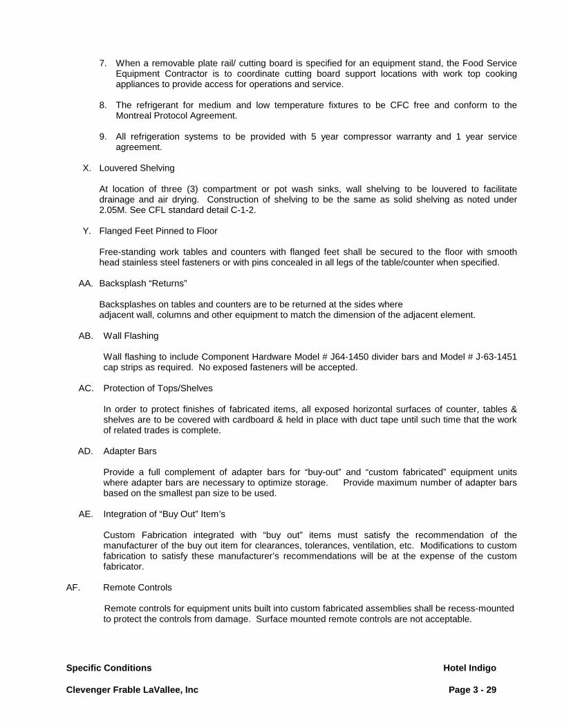
Specific Conditions Hotel Indigo Clevenger Frable LaVallee, Inc Page 3 - 29
7. When a removable plate rail/ cutting board is specified for an equipment stand, the Food Service Equipment Contractor is to coordinate cutting board support locations with work top cooking appliances to provide access for operations and service.
8. The refrigerant for medium and low temperature fixtures to be CFC free and conform to the
Montreal Protocol Agreement. 9. All refrigeration systems to be provided with 5 year compressor warranty and 1 year service
agreement.
X. Louvered Shelving At location of three (3) compartment or pot wash sinks, wall shelving to be louvered to facilitate
drainage and air drying. Construction of shelving to be the same as solid shelving as noted under 2.05M. See CFL standard detail C-1-2.
Y. Flanged Feet Pinned to Floor Free-standing work tables and counters with flanged feet shall be secured to the floor with smooth
head stainless steel fasteners or with pins concealed in all legs of the table/counter when specified. AA. Backsplash “Returns” Backsplashes on tables and counters are to be returned at the sides where
adjacent wall, columns and other equipment to match the dimension of the adjacent element. AB. Wall Flashing Wall flashing to include Component Hardware Model # J64-1450 divider bars and Model # J-63-1451
cap strips as required. No exposed fasteners will be accepted. AC. Protection of Tops/Shelves In order to protect finishes of fabricated items, all exposed horizontal surfaces of counter, tables &
shelves are to be covered with cardboard & held in place with duct tape until such time that the work of related trades is complete.
AD. Adapter Bars Provide a full complement of adapter bars for “buy-out” and “custom fabricated” equipment units
where adapter bars are necessary to optimize storage. Provide maximum number of adapter bars based on the smallest pan size to be used.
AE. Integration of “Buy Out” Item’s Custom Fabrication integrated with “buy out” items must satisfy the recommendation of the
manufacturer of the buy out item for clearances, tolerances, ventilation, etc. Modifications to custom fabrication to satisfy these manufacturer’s recommendations will be at the expense of the custom fabricator.
AF. Remote Controls Remote controls for equipment units built into custom fabricated assemblies shall be recess-mounted to protect the controls from damage. Surface mounted remote controls are not acceptable.

Specific Conditions Hotel Indigo Clevenger Frable LaVallee, Inc Page 3 - 30
2.08 MILLWORK EQUIPMENT
A. Workmanship and Fabrication: The following general requirements shall govern the construction of millwork built fixtures, except
where otherwise noted.
1. Work shall be performed by skilled craftsmens of the trade and shall be of the highest quality throughout, in such a manner as to fulfill the intent of the Contract Documents.
2. Fabrication, finishing, and installation of millwork specified in this section, shall be by one
Contractor and shall not be sublet unless specifically approved by the Designer. 3. Woodwork to be 3/4" plywood throughout except at wet or moisture areas (such as sinks, beverage
counters, water stations,) where 3/4" marine plywood is required. 4. Woodwork counters shall be constructed to support the full weight of operating appliances without
any deflection of the counter top. Where cut-outs are required in counter tops, appropriate framing needs to be provided around the cut-out to fully support the top in level position.
5. All miter joints shall be tight with no gaps or open spaces. Filling of miter joints with crack filler
prior to finishing is not acceptable. Loose joints shall be hairline, flat, in single plane, with no exposed screws, nails or other fasteners. All dimensions, reveals and joints shall be held exact.
6. All fixtures shall be assembled in single and complete units as the dimensions will permit shipment
to and installation at the building. Large pieces requiring sectional construction shall have their parts accurately fitted and aligned with each other, and provided with ample screws, glue and bolt blocks, tongues, grooves and splines, dowels, mortises and tenons, screws, bolts or suitable means of concealed fastening, as required to render the work substantial, rigid and permanently secured in proper position.
7. Sufficient additional material shall be allowed to permit accurate scribing to walls, floors and related
work, and due allowance made wherever possible for such shrinkage as may develop after installation. Single and sectional units shall be provided with adequate cleating, blocking, crating and other forms of protection as required to prevent damage, soiling and deterioration during transit, delivery, storage and handling.
8. Framing and blocking members shall be assembled with bolted and screwed connections and
should be secured to the structural backing with cinch, expansion screws or toggle bolts, as required; spaced and installed to insure ample strength and rigidity. Rails and stiles shall be mortised and tenoned, work neatly mitered and membered, all butt joints made flush and smooth, and all permanent joints made up with water resistant glue. All fixtures shall be assembled without face screws or nails, except where it may be necessary to attach trim items. All face screws or nails which are necessary shall be countersunk and plastic wood or wood plugs used to cover head, and the plug neatly touched up. The heads of all screws used in any assembly shall be countersunk below the surface.
B. Joints
1. Mortise and tenon, spline, dowel and/or pin block and glue work to avoid use of nails wherever
practical. Make butt joints with an approved device for prevention of separation of members. Blind nail and conceal.

Specific Conditions Hotel Indigo Clevenger Frable LaVallee, Inc Page 3 - 31
C. Plastic Laminate (HDPL)
1. Plastic laminate shall be bonded to all exposed surfaces with contact cement fast bond #30, as
manufactured by 3-M Products Company, or equal, to minimum 3/4" fir faced plywood applied under high pressure. Reject plastic laminate or plastic backing shall be used to prevent warping, unless otherwise specified. All edges shall be carefully sanded to smooth finish, removing burns, nicks and cut marks.
2. Plastic laminate joints shall be finished without wavy and unsightly joints. Joints need not be
mitered except if specified. Hand sand edges to a slight chamfer. 1. Plastic Laminate products to be High Pressure Decorative Laminate as specified under AWI
Standards. 4. Foodservice Equipment Contractor to confirm installation requirements with
food service equipment manufacturer where equipment units penetrate the counter top. Foodservice Equipment Contractor to coordinate installation requirements suggested by the manufacturer with the Millwork Contractor.
D. Doors, Hinged
1. Hinged doors shall be fabricated of 3/4" thick plywood with plywood full perimeter edging with
plastic laminate on face and self-edging on exposed sides. Door hinges, pulls and catches shall be supplied and installed as detailed and to be as manufactured by HAFELE or equal.
E. Doors, Sliding
1. Sliding doors shall be fabricated of solid core plywood with hardwood edges and constructed
similar to hinged doors. Doors shall be mounted on E-Z Glides track. Doors shall be removable without the use of tools. Rubber stops shall be provided concealed in end stile or mullion.
F. Doors, Tambour Sliding
1. Tambour sliding doors shall be fabricated of individual hardwood slats, 3/8" by 3/4" round on 2
edges and glued to 20 ounce duck canvas or reject elastic vinyl plastic or equal and shall be provided with hardwood end stile with integral door pull. Track shall be lined with laminated plastic or equally smooth surface and guides at top and bottom shall be fabricated hardwood. Provide lock-pin for sliding doors.
G. Access Panels/Louver Panels/Louver Doors
1. Access Panels: Shall be fabricated of 3/4" thick plywood and shall be fabricated to be removable
for access. Each access panel shall be provided with 2 (two) magnetic catches at top and 2 (two) 3/16" positioning pins at bottom (unless otherwise specified or detailed on drawings).
2. Louvered Panels: Are required in woodwork at all locations where proper ventilation is necessary
for the efficient performance and operation (exhaust and/or supply) of the food service equipment compressor.
Types: (When specified)
a. Louvered panel constructed same as Access Panel except provided with louvers, spaced to
conceal equipment yet provide adequate ventilation. Provide black color screening on rear with protective edges to prevent tearing.
b. Louvered panel to be extruded aluminum, Model ADL-5TC-4 W/RSM 4 Frame, spray painted to match plastic laminate of woodwork, as manufactured by Reliable Inc., Geneva, AL (205)

Specific Conditions Hotel Indigo Clevenger Frable LaVallee, Inc Page 3 - 32
684-3621 or equal. c. FSEC to coordinate size, quantity and location of louvered opening for sufficient ventilation of
food service equipment. 3. Louvered Doors:
a. Must have concealed hardware to resemble access panels. Doors to have nylon roller friction
type heavy duty catch and heavy duty concealed stainless steel adjustable hinge. b. Plastic laminate fronts. Provide kiln dried pine shutter type slats. Wood to be free of knots wit
smooth grain, epoxy painted to match laminate selection. No raw wood surfaces will be acceptable. Paint or laminate as needed between slats.
c. Slats to be fixed, positioned to conceal equipment from sight. d. Provide black color screening/mesh on rear of door with protective edges to prevent tearing. e. FSEC to coordinate size, quantity and location of louvered opening for sufficient ventilation of
food service equipment
H. Drawers
1. Drawers shall have dovetail construction, well glued and blocked. Fronts shall be not less then 3/4" thick plywood. Sides and back shall be 1/2" thick fabricated of Birch, Maple, or Sycamore except where extension slides are used, in which case the sides shall be 5/8" thick. Bottom shall be milled into fronts and sides. Drawers shall be provided with suitable stops. Provide pulls as detailed or specified and to be as manufactured by HAFELE or equal.
2. The inside surfaces of all drawers shall receive one coat of Penetrating Primer and one coat of
glass lacquer. I. Painted Finishes
1. Painted finishes shall have exposed surfaces free from defects and blemishes that would show after being finished, regardless of grade specified. All surfaces specified to receive a paint or enamel finish shall receive one crosscoat of lacquer type undercoat. The undercoat shall be of appreciably different color from that of the finish coat, and of proper ground color with relation to the finish coat. After the undercoat has been thoroughly dried, surfaces shall be sanded smooth and two coats of enamel shall be applied. Back painting shall be provided for all cabinet and woodwork prior to installation.
J. Interior & Wall Shelves
1. Cabinet interiors and wall shelves shall be laminated as specified under Section 3 Plastic
Laminate. K. Corian Tops
1. Surfaces shall be Corian (methyl methacrylate binder) as manufactured by E.I. DuPont Nemours &
Co., Inc. Wilmington, DE, or approved equal.

Specific Conditions Hotel Indigo Clevenger Frable LaVallee, Inc Page 3 - 33
2. Color and pattern shall be selected by the Designer, and physical properties shall conform to manufacturer's standard specifications. The material shall be homogenous; not coated laminate, or of composite construction.
3. Corian sheet shall be 1/2" for counter tops, and backsplashes unless otherwise specified. 4. General installation to conform with manufacturers standard details in order to maintain product
warranty, i.e. cut outs for drop in equipment. 5. Foodservice Equipment Contractor to confirm installation requirements with
food service equipment manufacturer where equipment units penetrate the counter top. Foodservice Equipment Contractor to coordinate installation requirements suggested by the manufacturer with the Millwork Contractor.
L. Measurements
1. Before proceeding with fabrication of woodwork required to be fitted to other construction, obtain
field measurements and certify dimensions and Shop Drawing details as required for accurate fit.
M. Pre-Cut Openings/Templates 1. Contractor to obtain templates and or accurate dimensions for sizing of cutouts required in millwork
from Food Service Equipment Contractor so that cutouts can be completed in shop.
N. Wood Base Construction At Floor Drain 1. Fabricate notch in base for floor drain locations as required in employee areas (field dimensioning
required). 2. In public areas, provide boxed out opening within base cabinet for floor drain locations (field
dimensioning required). Provide stainless steel liner in box with top flange sealed in place.
O. Submittal 1. Shop Drawings:
a. Submit Shop Drawings showing location of each item, dimensioned plans and elevations, large scale details, attachment devices and other components including hardware schedule(s).
b. All the required cut-outs for food service equipment to be properly sized and located on
Millwork Shop Drawings. Contractor to confirm locations of cut-outs with the Food Service Equipment Contractor prior to submitting Millwork Shop Drawings for approval.
c. The Contractor shall not be relieved of responsibility for any deviation from the requirements of
the Contract Documents unless the Contractor has received written approval for the deviation. d. Coordinate submittal requirement with FSE contractor. See 1.11 Submittals of Specific
Conditions, K. Coordination Drawings.
P. Product, Delivery, Storage and Handling
1. Protect woodwork during transit, delivery, storage and handling to prevent damage, soiling and deterioration.

Specific Conditions Hotel Indigo Clevenger Frable LaVallee, Inc Page 3 - 34
Q. Job Conditions
1. Examine site conditions affecting this Work. Report unsatisfactory conditions to the General Contractor and do not proceed until those conditions have been corrected. Commencing work implies acceptance of conditions existing at the site as satisfactory to the outcome of this Work.
2. This Contractor shall advise the General Contractor of temperature and humidity requirements for
woodwork installation areas. 3. Fire Retarding:
a. Where required by code, all required materials are to be treated with fire retardant chemicals to
achieve the required flame spreading performance rating. Retardant chemicals must be a type approved by local authorities.
b. Provide all fire retardant treated blocking as required for installation of Woodwork.
R. Execution
1. Inspection: This Contractor must examine the substrates and conditions under which the work is to be installed
and notify the Designer in writing of unsatisfactory conditions. Do not proceed with work until unsatisfactory conditions have been corrected in a manner acceptable to this Contractor.
2. Preparation: Prior to installation of woodwork, examine shop fabricated work for completion and complete work
as required including back priming and removal of packing. 3. Installation:
a. Install the work plumb, level, true and straight with no distortions. b. Shim, as required, using concealed shim and/or levelers. Install to a tolerance of 1/8" in 8'-0"
for plumb and level, and with 1/32" maximum offset in flush adjoining surfaces, 1/8" maximum offsets in revealed adjoining surfaces.
c. Scribe and cut work to fit adjoining work and refinish cut surfaces or repair damaged finish at
cuts. Scribe base as required to hard floors, such as wood and marble.
4. Wood Base/Standing and Running Trim: Install with minimum number of joints possible, using full-length pieces (from maximum length of
lumber available) to the greatest extent possible. No joints in verticals (standing). Stagger joints in adjacent and related members. Blind fasten all joints. No exposed fasteners shall be accepted.
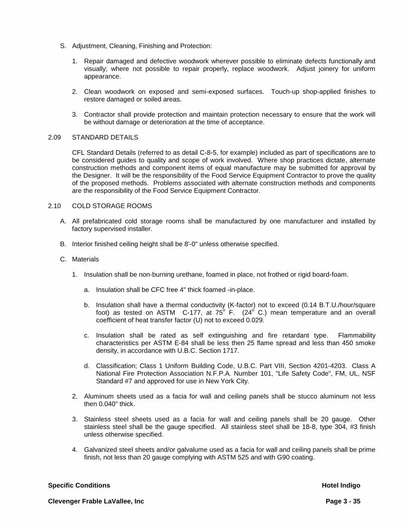
Specific Conditions Hotel Indigo Clevenger Frable LaVallee, Inc Page 3 - 35
S. Adjustment, Cleaning, Finishing and Protection:
1. Repair damaged and defective woodwork wherever possible to eliminate defects functionally and visually; where not possible to repair properly, replace woodwork. Adjust joinery for uniform appearance.
2. Clean woodwork on exposed and semi-exposed surfaces. Touch-up shop-applied finishes to
restore damaged or soiled areas. 3. Contractor shall provide protection and maintain protection necessary to ensure that the work will
be without damage or deterioration at the time of acceptance. 2.09 STANDARD DETAILS
CFL Standard Details (referred to as detail C-8-5, for example) included as part of specifications are to be considered guides to quality and scope of work involved. Where shop practices dictate, alternate construction methods and component items of equal manufacture may be submitted for approval by the Designer. It will be the responsibility of the Food Service Equipment Contractor to prove the quality of the proposed methods. Problems associated with alternate construction methods and components are the responsibility of the Food Service Equipment Contractor.
2.10 COLD STORAGE ROOMS
A. All prefabricated cold storage rooms shall be manufactured by one manufacturer and installed by factory supervised installer.
B. Interior finished ceiling height shall be 8'-0" unless otherwise specified. C. Materials
1. Insulation shall be non-burning urethane, foamed in place, not frothed or rigid board-foam.
a. Insulation shall be CFC free 4" thick foamed -in-place. b. Insulation shall have a thermal conductivity (K-factor) not to exceed (0.14 B.T.U./hour/square
foot) as tested on ASTM C-177, at 75o F. (24o C.) mean temperature and an overall coefficient of heat transfer factor (U) not to exceed 0.029.
c. Insulation shall be rated as self extinguishing and fire retardant type. Flammability
characteristics per ASTM E-84 shall be less then 25 flame spread and less than 450 smoke density, in accordance with U.B.C. Section 1717.
d. Classification; Class 1 Uniform Building Code, U.B.C. Part VIII, Section 4201-4203. Class A
National Fire Protection Association N.F.P.A. Number 101, "Life Safety Code", FM, UL, NSF Standard #7 and approved for use in New York City.
2. Aluminum sheets used as a facia for wall and ceiling panels shall be stucco aluminum not less
then 0.040" thick. 3. Stainless steel sheets used as a facia for wall and ceiling panels shall be 20 gauge. Other
stainless steel shall be the gauge specified. All stainless steel shall be 18-8, type 304, #3 finish unless otherwise specified.
4. Galvanized steel sheets and/or galvalume used as a facia for wall and ceiling panels shall be prime
finish, not less than 20 gauge complying with ASTM 525 and with G90 coating.
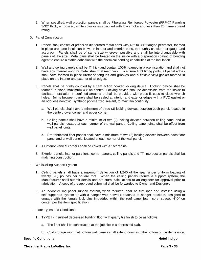
Specific Conditions Hotel Indigo Clevenger Frable LaVallee, Inc Page 3 - 36
5. When specified, wall protection panels shall be Fiberglass Reinforced Polyester (FRP-X) Paneling 3/32" thick, embossed, white color or as specified with low smoke and less than 25 flame spread rating.
D. Panel Construction
1. Panels shall consist of precision die formed metal pans with 1/2" to 3/4" flanged perimeter, foamed
in place urethane insulation between interior and exterior pans, thoroughly checked for gauge and accuracy. Panels shall be of same size wherever possible and shall be interchangeable with panels of like size. Metal pans shall be treated on the inside with a preparation coating of bonding agent to ensure a stable adhesion with the chemical bonding capabilities of the insulation.
2. Wall and ceiling panels shall be 4" thick and contain 100% foamed in place insulation and shall not
have any internal wood or metal structural members. To ensure tight fitting joints, all panel edges shall have foamed in place urethane tongues and grooves and a flexible vinyl gasket foamed in place on the interior and exterior of all edges.
3. Panels shall be rigidly coupled by a cam action hooked locking device. Locking device shall be
foamed in place, maximum 48" on center. Locking device shall be accessible from the inside to facilitate installation in confined areas and shall be provided with press-fit caps to close wrench holes. Joints between panels shall be sealed at interior and exterior edges with a PVC gasket or an odorless nontoxic, synthetic polymerized sealant, to maintain continuity.
a. Wall panels shall have a minimum of three (3) locking devices between each panel, located in
the center, lower corner and upper corner. b. Ceiling panels shall have a minimum of two (2) locking devices between ceiling panel and at
wall panels, located at each corner of the wall panel. Ceiling panel joints shall be offset from wall panel joints.
c. Pre-fabricated floor panels shall have a minimum of two (2) locking devices between each floor
panel and at wall panels, located at each corner of the wall panel.
4. All interior vertical corners shall be coved with a 1/2" radius. 5. Exterior panels, interior partitions, corner panels, ceiling panels and "T" intersection panels shall be
matching construction.
E. Wall/Ceiling Support System
1. Ceiling panels shall have a maximum deflection of 1/240 of the span under uniform loading of twenty (20) pounds per square foot. When the ceiling panels require a support system, the Manufacturer shall submit details and structural calculations to an engineer for approval prior to fabrication. A copy of the approved submittal shall be forwarded to Owner and Designer.
2. An indoor ceiling panel support system, when required, shall be furnished and installed using a
self-supported system or with a hanger wire network attached to hanger brackets, designed to engage with the female lock pins imbedded within the roof panel foam core, spaced 4'-0" on center, per the item specification.
F. Floor Types and Conditions
1. TYPE I - Insulated depressed building floor with quarry tile finish to be as follows:
a. The floor shall be constructed at the job site in a depressed slab. b. Cold storage room flat bottom wall panels shall extend down into the bottom of the depression.
Specific Conditions Hotel Indigo Clevenger Frable LaVallee, Inc Page 3 - 37
G.C. to provide two (2) 2" thick layers (or as specified) of rigid board foam urethane with staggered joints in depression over vapor barrier, installed after walls are in place. In freezers use Class I for floor insulation of not less than R-8/inch at 20°F.
c. On top of floor insulation G.C. to provide a protective covering of 15 pounds felt. Over lap
joints 6". Flash up sides to height of wall base. d. When indicated on contract documents, finished floor outside the cold storage rooms shall
ramp up 1" to the floor inside by the G.C. The finished floor between cold storage rooms shall be ramped as well when indicated.
e. Provide coved base quarry tile (by General Contractor) at interior perimeter and at exposed
exterior panel walls.
2. TYPE II - Pre-fabricated Floor Types to be as follows (per itemized specifications):
a. The 4" floor shall be pre-fabricated NSF-approved metal-clad, foamed-in-place urethane
insulated panels. Floor panel construction and insulation to match that of wall and ceiling panels. Floor panels shall be fully coved with a minimum of 3/8" radius. The exposed wearing surface will be metal-clad with a finish as indicated in the itemized specifications. Exterior bottom face of floor shall be clad with galvanized steel or galvalume.
b. When indicated in itemized specifications, the 4" floor panels are to be heavy-duty with
factory structural support that transfers the weight-bearing capacity to the building sub-floor via internally foamed-in-place supports on approximate 12" centers.
c. The 2" floor shall be pre-fabricated NSF-approved metal-clad, foamed-in-place urethane
insulated panels. Floor panel construction and insulation to match that of wall and ceiling panels. Floor panels shall be fully coved with a minimum of 3/8" radius. The exposed wearing surface will be metal-clad with a finish as indicated in the itemized specifications. Exterior bottom face of floor shall be clad with galvanized steel or galvalume.
NOTE: Heavy-duty structural floor option is not available on 2" floors.
d. When indicated in itemized specifications, the wearing surface is to be finished with Altro Atlas 40, First Choice or Protect-All (Oscoda Plastics) seamless flooring with a 6" coved base at interior perimeter of floor.
The factory provided floor is to be 5/8" foamed-in-place marine-grade plywood. The standard factory metal skin is to be eliminated so that the seamless floor can adhere directly to this plywood surface.
e. Interior/exterior ramps with non-slip treads shall be furnished where specified and/or
indicated on drawings.
f. Provide coved base quarry tile at exposed exterior panel walls. G. Door and Door Frames
1. Door sizes shall be 36” wide x 84” high or as specified, hinged as indicated on plan. Door shall be
able to remain open when opened over 120o
.
2. Door shall be infitting, flush mounted, double panned 20 gauge stainless steel interior and exterior panels or as specified with foamed-in-place urethane insulation, 4" thick minimum. Same construction as for wall panels. Corners of doors shall be Heliarc welded, ground and polished.
3. Furnish and install a removable threshold at each low temperature door, constructed of 16 gauge

Specific Conditions Hotel Indigo Clevenger Frable LaVallee, Inc Page 3 - 38
stainless steel. 4. Provide a heating element on the ambient side of each freezer/ food bank door frame head, jambs
and threshold. The heating element shall be a dual 120 volt, 240 watt with thermostatic control, factory prewired to a "GS" splice box located above the door on the roof exterior. Division 26 shall make final connection.
5. Gasket shall be extruded polyvinyl chloride with vulcanized corners and continuous magnetic core
at sides and top of door frame. The stainless steel jamb facing shall extend to protect the gasket.
6. Door shall be adjusted to be self-closing after installation and floor is finished. 7. Sill wipers for Type I floors shall be adjustable, extruded neoprene secured by removable stainless
steel retainer strip and fasteners. 8. Each hinged door shall have:
a. Kick plate of 1/8” diamond plate 3'-0" high and full width of door. Mount on the interior and
exterior face of each door and door section. b. Hinges, three (3) each per door, shall be Kason 1253 Series, or approved equal, cam lift, zinc
die cast and polished chrome plated c. Latch shall be Kason 1239 Series, or approved equal, heavy duty chrome plated brass with
adjustable keeper, interior safety release and provisions for padlocking. Padlock by others. d. Door closer shall be Kason Model 1095 or approved equal. e. Hardware shall be mounted with 12 gauge reinforced steel tapping plates and machine screws. f. Heated viewport approximately 14" square (or as specified), minimum triple thermopane glass.
Viewport wiring to be concealed within door and out top of door, complete with flex cable to recessed splice box within door section.
g. 2-1/2” dial thermometer flush mounted, to monitor the interior temperature of cold storage
room, surface mounted on door panel. When specified, provide door panel with flush mounted 4-1/2" diameter dial thermometer in lieu of factory standard.
h. Schlage, or equal, mortise lock with recessed thumb turn on exterior door only.
9. Door section shall be self supporting constructed similar to wall panels with 4" foamed in place
urethane core. No wood framing will be permitted. 10. Each sliding door opening shall have a secondary door similar to Eliason FCD-120 or equal.
Door(s) to be clear PVC with top mounted gravity operated hinge sized to suit the opening per the manufacturer’s recommendations.
H. Light Fixtures and Switches
1. Quantity of light fixtures shall be as indicated on the electrical plan. 2. Light fixtures;
a. Incandescent: Kason # 1801, light fixture with # 1804 plastic coated globe with wire guard and
sized to receive one 100 watt bulb unless otherwise specified. b. Fluorescent: Shall be Lithonia Commercial Model DMW 240 120 CW 48" double fluorescent
Specific Conditions Hotel Indigo Clevenger Frable LaVallee, Inc Page 3 - 39
light fixtures with low temp ballast designed to operate at the temperature of the Cold Storage Room(s).
3. Cold storage rooms with doors at each end shall have three way switches on the exterior. 4. Light switches shall be three way or four way, AC, pre-switch, mounted in recessed "FS" boxes
with grey Hypolan, weatherproof plate and unbreakable red plastic pilot light lens constant burning on interior and indicating on exterior.
2. Light switches shall be factory mounted on the latch side of doors and prewired with rigid conduit and
wiring run within the wall panel, terminated in a vapor tight splice box mounted on the interior wall near ceiling. Manufacturer shall provide a 1-1/4" diameter hole in ceiling panel with a loose escutcheon through which Division 26 shall make final connections. 6. F.S.E. Contractor shall furnish the required number of incandescent /fluorescent bulbs/tubes for
each light fixture.
I. Audio-Visual Temperature Alarm
1. When specified, an audio visual temperature alarm shall be furnished for each cold storage room. Unless specified otherwise, unit shall be Modularm Corporation (or equal) flush mounted with stain-
less steel cover plate, mounted on the exterior door section of each cold storage room, pre-wired with rigid conduit and wiring run within the wall panel using "FS" recessed box on the exterior and terminated in a "GS" splice box mounted on the interior near the ceiling. Manufacturer shall provide a 1-1/4" diameter hole in ceiling panel with loose escutcheon through which Division 26 shall make final connection. Where there are multiple compartment cold storage rooms, alarms will be ganged into a common alarm panel.
2. Temperature alarm system shall consist of solid state audio alarm, silence button, trouble light,
digital read out, indicator/failure lights, controller, time clock and stainless steel cover and battery back-up.
3. Control panel for the temperature alarm system to be located where shown on plans. F.S.E.
Contractor to coordinate with appropriate trades for installation of panel. 4. Provide contacts for eventual connection to building alarm system. 5. When the door does not open into an ambient area, the temperature alarm system be factory
installed, as specified above, in a remote wall panel with an ambient face that will not interfere with other equipment and functions and identified with a name plate of the room being monitored. The sensor capillary shall be extruded as required and, when necessary, run in electrical conduit. Provide escutcheon plates on each side of each partition penetrated.
J. Food Banks
1. When specified, furnish Food Banks with a Honeywell Model DR-4300-12 chart recorder or equal.
Chart recorder to be 7-day record, single pen unit with probe. 2. Chart recorder to be located where shown on plans. F.S.E. Contractor to coordinate with
appropriate trades for installation of panel. 3. Conduit, control wiring and interconnection between probe (at blower coil location) and chart
recorder to be by Division 26.

Specific Conditions Hotel Indigo Clevenger Frable LaVallee, Inc Page 3 - 40
K. Door Fan Switch
1. When specified, a door fan switch shall be provided for each low-temperature cold storage room, when it opens into a non-refrigerated area, to shut off evaporator coil fan motors when the door is opened.
2. Door fan switch shall be factory mounted on the door jamb and prewired with rigid conduit and
wiring within the wall panel to a splice box located on the interior near the ceiling. Manufacturer shall provide a 1-1/4" hole in ceiling panel with a loose escutcheon through which Division 26 shall make interconnection to the evaporator coil(s) fan motors.
L. Closure Panels
1. Closure panels shall be furnished and installed to close the space between the exterior top of the
cold storage room and the finished ceiling of the building. 2. Panels to match exterior panel finish. Panels to be lift out type with side turned in to form a pan. At
ceilings, securely fasten a channel and at face of cold storage room, securely fasten an angle for panel to slip into. Channel and angle to match panel material.
3. When exterior finish is FRP-X, the closure panel shall be white stucco aluminum. 4. When the area does not have a finished ceiling, closure panels shall not be required, unless
otherwise specified or required by the health department.
M. Trim
1. Vertical trim strips and angles to match cold storage room exterior finish. Trim to be applied with a minimum of exposed fasteners to fully seal cold storage room adjacent walls, etc.
2. The FRP-X paneling with a "J" end cap molding is to be extended past the end of the cold storage
room wall to the building wall and caulked with silicone as required.
N. Ramps and Sills
Ramps and sills when required shall be prefabricated 16 gauge stainless steel ramps with 14 gauge galvanized reinforcing and urethane foamed in place insulation. Wearing surface to have Altro Atlas 40 or ProtectALL (Oscoda Plastics). See specifications and drawings for size and shape. All door sections shall be provided with minimum 14 gauge stainless steel sill plate complete with heater cable as stated under door section. Sill to be either built into ramp/pre-fabricated floors or to be part of door section on insulated depressed building floors. Sills to be removable for replacement of heater cable.
O. Utility Penetrations
1. Provide openings in ceiling and wall panels to accommodate all electrical, refrigeration and drain
lines. 2. Seal all openings with silicone after lines have been run and before installation of escutcheons.
P. Escutcheons
1. Provide sufficient quantity of 5" diameter blank stainless steel escutcheons to trim all interior and exposed exterior penetrations.
2. Provide cutting of proper size hole in blanks and panel penetrations.

Specific Conditions Hotel Indigo Clevenger Frable LaVallee, Inc Page 3 - 41
Q. Pressure Relief Vent
1. Pressure relief vent shall be factory installed at each low-temperature cold storage room door. 2. Pressure relief vent shall be electrically heated, 120 volt and have aluminum screen.
R. Corner Guards
1. Provide corner guards on the exterior outside corners. The corner guards shall be 4"x4"x48" 16 gauge stainless steel secured to wall panels with a full bed of contact adhesive. When FRP-X finish is specified, corner molding shall be omitted behind the corner guard.
2. Corner guards on the interior outside corners shall be 2" x 2" by height of wainscot or 48" high 16
gauge stainless steel secured to wall panels with a full bed of contact adhesive. When FRP-X is specified, outside corner molding shall be omitted behind corner guards.
3. Provide full height corner guards on exposed corners of interior door casings. S. Divider with Gate
Divider and gate, when specified, shall be aluminum expand-x where indicated on drawings.
1. Panel mesh shall be flattened aluminum expand-x heliarc welded to aluminum frame. 2. Frame shall be 1-1/2" by 1-1/2" by 1/8" aluminum 6061-T6 angle. Frame shall have 3" space at
bottom and 6" space at top. 3. Horizontal stiffeners shall be 1-1/2" x 1-1/2" x 1-1/8" aluminum angle. 4. Floor plates shall be 3" by 3" x 1/4" aluminum heliarc welded to angle posts. 5. Gate shall be of same construction as divider, 2'-10" wide with lock similar to that specified for
insulated doors.
T. Rub Rails - Interior/ Exterior
When specified, rub rails shall be located where indicated on plans.
1. Rub rails shall be continuous lengths of 18 gauge stainless steel "U" shaped hat section secured to wall with stainless steel sheet metal screws 18" O.C. Exposed ends shall be bevel cut, capped, welded, ground and polished.
U. Strip Curtain Strip curtain when specified, shall be Model M-200 manufactured by Curtron Industries Inc. with closed
brackets, or approved equal. V. Door Locking Bars
1. Door locking bars, when specified, shall be 1/8" by 2" stainless steel two piece, hinged and secured
at each end with interior safety release. Bar shall swivel and where the ends meet in the center shall have a 2" long 900
"L" drilled to receive padlock, padlock by others.
2. When a door locking bar is specified, the latch specified in paragraph G.10.C shall be replaced with a Kason Model 577 polished chrome plated door pull, or approved equal.
Specific Conditions Hotel Indigo Clevenger Frable LaVallee, Inc Page 3 - 42
W. Identification Signs
1. At exterior of each Cold Storage Room provide and permanently affix engraved plastic name plates with maximum 3/4" high letters and number identifying each Cold Storage Room and Refrigeration System to match "as built" diagram. Name plate to be mounted with adhesive below respective digital thermometer alarm. A similar name plate with 1/2" high letters is to be installed in a like manner on the evaporator coil(s) at all other items having a remote Refrigeration System.
2.11 REMOTE REFRIGERATION SYSTEMS
A. All remote refrigeration systems shall be furnished and installed by one contractor, unless otherwise specified. Provide all components necessary for a complete and operable system. System to be fully capable of satisfying the refrigeration requirements for each fixture as defined by the manufacturer of each fixture.
B. It is the responsibility of Division 114000 to follow all applicable codes and current refrigeration industry
standards and practices when determining line sizes and installing and starting up remote refrigeration equipment.
C. Compressor and Condensing Units
1. Units shall be factory assembles complete with hermetic units below 1 HP, semi-hermetic units 1
HP and larger, air or water cooled condenser, depending upon building conditions and specifications, high-low pressure controls, suction accumulator on low temperature system, sight glass, liquid line dryer, suction and discharge service valves, liquid receiver, and electric control panel. The electrical control panel shall be furnished with magnetic motor starter, defrost timer clock, and contractors in accordance with "Refrigeration Schedule". Compressor capacities shall be based on Air Conditioning and Refrigeration Institute (A.R.I) Standards.
The refrigerant for medium and low temperature fixtures to be CFC free and conform to the
Montreal Protocol Agreement. 2. Capacities shall be based on the following:
a. Compartment temperature and evaporating temperature greater than 32oF (0o
C) 18 to 20 hours operations.
b. Compartment temperature greater than 32oF (0oC) and evaporating temperature less than 32oF (0o
C) 16 hours operation.
c. Compartment temperature and evaporating temperature less than 32oF (0o
C) 18 hours operation.
3. Condensing units shall be mounted on a steel base to effect a quiet operation. All rotating parts to be carefully balanced for minimum vibration and lubricated with forced or splash oil system. Receiver shall be sized for a complete pump down of the system and shall be shell type with fusible plug.
4. Compressor units to be provided with suction and discharge back setting type service valves and
standard machinery finish. 5. Motors shall be single speed, maximum 1750 R.P.M. compound wound ball bearings or sleeve
bearing. Double squirrel cage motors with high starting torque set and low starting current to be used in a 3 phase application.
6. All machines to be equipped with quick acting type high-low pressure control switches having
adjustable range and differential and high pressure cut-out. Cut-out to be automatic reset type.
Specific Conditions Hotel Indigo Clevenger Frable LaVallee, Inc Page 3 - 43
7. For air-cooled units the condenser shall be a standard manufactured part of the equipment.
Condensing temperatures shall be based upon (100oF 38o
C) ambient air.
8. Other components and accessories, such as suction filter and crank case heater shall be furnished when specified in the itemized specifications.
D. Motor Starters-Contactors
1. All single phase motors shall be provided with mounted and internally wired contactors, except
where pre-wired units are furnished without contactors. Single phase compressors shall be provided with built-in thermal and electrical overload protection.
2. All three phase motors shall be provided with magnetic type starters with quick trip overload
elements matched for motor amperage except where overload protection is built into the compressor motor and the manufacturer supplies a contactor instead of a starter. Overload heater element shall be sized according to manufacturer's recommendations. Compressor motor starters shall be definite purpose starters with manual reset.
3. Starters shall be installed upon surfaces free from excessive vibrations. 4. Where starters are required for installation in a motor control center, make and model of control
center shall be verified and starters provided to match.
E. Oil Separator
1. Provide oil separators, except when Compressor Manufacturer requires otherwise, 34oF, (1o
C) and below and install as near as possible to the compressor. The return line shall be connected to the top of the crank-case above the oil level. Where compressor does not have connection for oil return line from separator, connect to a tee in the suction line adjacent to the compressor. Exposed oil return line to be provided with shut-off valve of the packless stem type.
F. Compressor Racks
1. Racks shall be of the number of tiers and quantity to accommodate the number of condensing units specified for each rack assembly and allow for service clearance and ventilation. Review and confirm access into building or housing requirements to roof top locations.
2. Racks shall be fabricated with structural steel of size and quantity to properly support the
equipment to be installed on the rack. In special applications where building access is limited, construct rack framing with Dexion of Unistrot material.
3. Racks shall be all welded construction with welds ground smooth. 4. After completion of fabrication the complete rack shall be cleaned, primed and painted with top
quality oil base enamel. 5. Each rack shall be equipped with a pre-wired duplex outlet. 6. Racks shall be pre-wired to a circuit breaker panel and pre-plumbed to a header (when specified
water cooled) requiring a single point electrical and plumbing connection. 7. Racks shall have UL or equivalent approval. 8. Special Conditions: For custom built racks for individual condensing units provide Dxion Angle Iron.

Specific Conditions Hotel Indigo Clevenger Frable LaVallee, Inc Page 3 - 44
G. Coils and Cooling Units
1. Units shall be direct expansion type of size and design to effect required temperature, humidity and to suit application intent.
2. Units shall be hung from the ceiling with 1/2" nylon rods with plated steel nuts and washers. Rods
shall extend through ceiling to bracing adequate for the suspended weight. Bracing shall be furnished as required, penetrations shall be sealed and trimmed with escutcheon plates.
3. Units shall be installed tight to ceiling. All installations adjacent to walls shall be set out a minimum
distance conforming to manufacturer's directions, to ensure proper air circulation and performance. 4. Units with fan or blower and motor shall have thermal overload protection and be wired as
indicated in "Refrigeration Schedule". 5. Defrost cycle shall be based on the following:
a. Coils for 32oF (0o
C) and lower shall have an electric defrost controlled by a time clock mounted on the compressor rack or at evaporators locations inter-wired by Division 26.
b. Coils for 33o (0.6oC) and 34oF (1o
C) shall have an air defrost controlled by a time clock mounted on the compressor rack or at evaporators locations inter-wired by Division 26.
c. Coils for temperature above 34oF (1o
C) shall have an air defrost in the off cycle controlled by proper sizing of the coil and the compressor.
6. Location of coils shall be coordinated with shelving and floor sink locations. 7. All coils for fabricated refrigerators and/or freezers shall be installed for accessibility and
replacement.
H. Penetration Sleeves and Plates
1. Service line penetrations of insulation to accommodate electrical conduit, refrigerant and drain lines, shall be limited to a minimum with service stubbed through insulation or locations predetermined by respective divisions.
2. Where service lines penetrate insulated walls, the opening shall be packed with caulking, before
trimming with escutcheon plate. 3. Where service lines penetrate building walls outside of foodservice areas, the opening shall be
packed with “Perma-Gum” and foam caulking. 4. All exposed ends of sleeves, both inside and outside of compartments, are to be trimmed with 24
gauge stainless steel escutcheon plates, furnished as blanks in which respective work divisions shall cut required line holes and install.
I. Refrigerant Piping
1. Copper tubing for refrigerant piping shall conform to ASTM standard specifications, serial
designation B-88. All piping shall be type "L" ACR hard copper or cleaned and sealed soft type "L" tubing, dry seal or equal as indicated. Forged or wrought copper fitting with sweat or soldered joints shall be used.
2. Tubing shall be cut only with a tube cutter and sized with a sizing tool.

Specific Conditions Hotel Indigo Clevenger Frable LaVallee, Inc Page 3 - 45
3. Piping shall be exposed to view as required by the standard safety code for mechanical refrigeration.
4. The liquid suction lines form condensing units to coil shall be sized and run as shown on the
“Refrigeration Schedule” and Refrigeration Drawings. 5. Piping run within cold storage rooms shall be finished with aluminum paint. 6. For exposed areas, accessible furred ceiling spaces and in walls or excavated trench type
installations, hard copper tubing shall be used. Exposed tubing shall be run in a manner to preclude damage by activities in the area; or shall be protected by conduit, furnished and installed as part of this contract. Conduit shall have water evacuated and both ends completely sealed.
7. For piping run in conduit through inaccessible areas, such as under slab on grade, continuous one
piece soft copper tubing shall be used with no joints. In lieu of large piping in conduit, especially vertical runs, random lines may be used; carefully fabricated and assembled to ensure equal pressure drop. Conduit required through inaccessible areas is provided and installed by the Electrical Division. Conduit shall have water evacuated, both ends completely sealed and be watertight.
8. Ends of lines shall be capped to prevent contamination and opened only at time of final connection. 9. Suction lines shall be sized for a maximum pressure drop from evaporator to compressor 2 lbs.
(0.9 kg.) for high and medium temperature systems, and of 1 lb. (0.45 kg.) for low temperature systems and shall allow gas velocities of not less than 750 FPM (3.8 M/sec.) in horizontal runs and 1500 FPM (97.6 M/sec.) in vertical risers. Liquid lines shall be sized for a maximum pressure drop of 3 lbs. (1.36 kg.) from receiver to evaporator.
10. Tubing runs shall be graded or pitched to prevent trapping of oil. Suction lines shall pitch 1/2"/10"-
0" minimum.
J. Joints and Connections 1. Fittings shall be long radius wrought copper only as manufactured by Mueller Brass Company or
equal. 2. Vertically run suction lines shall have one piece of manufactured oil "P" traps. Line to be sized for
proper velocity for oil return to compressor(s). 3. 1/8" NPT by 1/4 fl. half union for all suction and discharge service valves with 1/4 fl. cap. 4. Reduction in piping size shall be made with a manufactured reducer coupling. 5. Flare nuts shall be short forged or frost proof. 6. All surfaces to be joined must be prepared and cleaned. When soldering stop or solenoid valves,
wrap valves with moist fabric to absorb excessive heat. Stop valves shall be partly open. When soldering expansion valves or pressure regulating valves, remove power assembly, if necessary, to prevent damage by excessive heat.
7. Copper joints shall be made with Handy & Harmon "Sil-Fos" brazing alloy, "Phoson 15", "Silvaloy
15" or equal; melting point of 1185-1350oF; (640oC. - 732o
C.) silver content not less than 15%.
8. Copper to brass joints shall be made with Handy & Harmon "Easy Flo 45" brazing alloy "Silvaloy 45", "Mueller 122" or equal; melting point of 1125-1145oF, (607o-618o
C.) silver content not less than 45%.

Specific Conditions Hotel Indigo Clevenger Frable LaVallee, Inc Page 3 - 46
K. Hangers and Supports 1. For all piping not run in conduit, provide adjustable hangers, anchors or straps as required.
Hanger spacing shall not exceed 8'-0". 2. Insulated copper piping shall be provided with approved type sleeves at hanger points. 3. All insulated copper piping shall be isolated from supports by means of felt wrapping or with
"Trisolater" by Semco or approved equal. 4. Vertical piping shall be supported at intervals with spring type hangers or a substantial pipe at case
of the pipe. All horizontal pipe runs connected to vertical risers must be adequately supported. 5. For suspended conduit, support shall be by means of hanger permitting screw adjustments.
Sufficient hangers shall be used to provide support, allow expansion and limit vibration. L. Piping Sleeves
1. Provide sleeves through walls which allow for fully insulated lines. Extend sleeves entirely through
wall and dress each end with a chromium plated wall plate neatly fitted against the wall, securely fastened and sealed in place. All sleeves through wall shall be of standard weight steel pipe.
2. Piping lines and sleeves at wall or floor penetrations shall be caulked and made vermin proof at all
locations.
M. Piping Insulation 1. Suction lines run in conduit shall be insulated according to ambient and humidity conditions to
prevent condensation and freezing. 2. Refrigeration suction lines outside of refrigerated compartments, not run in conduit, shall be
insulated back to compressors with Armstrong Armaflex AP foamed plastic insulation or as determined by code. Thickness of material shall suit service, ambient and humidity conditions, to prevent condensation, minimum thickness 1/2" (15 mm.).
3. Cold Storage Room freezer drain lines extended through adjacent cooler compartments shall be
insulated with 1/2" (15 mm) minimum thickness of Armstrong Armaflex AP foamed plastic insulation to prevent condensation. Carefully seal end of insulation tight against cooler wall surface.
4. Piping for cooling water services or refrigerant piping exposed to freezing ambient temperatures
shall be insulated with 1/2" (15 mm) minimum thickness of Armstrong Armaflex AP foamed plastic insulation. Paint exterior installation with Armaflex paint.
5. Thickness of material shall suit service, ambient and humidity conditions to prevent condensation. 6. Joints shall be sealed with Armstrong 520 adhesive. Insulation shall be continuous through
clamps. Provide additional insulation where suction lines must be run within 12" or less of water or underground waste lines.
N. Heat Interchangers All blower controls, unit coolers, plate type evaporators and other evaporators where specified, are to
be provided with heat interchangers, with a capacity to match the condensing unit.
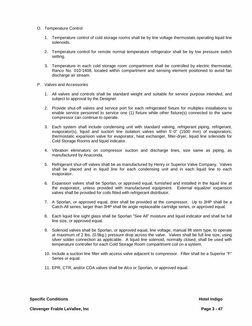
Specific Conditions Hotel Indigo Clevenger Frable LaVallee, Inc Page 3 - 47
O. Temperature Control
1. Temperature control of cold storage rooms shall be by line voltage thermostats operating liquid line solenoids.
2. Temperature control for remote normal temperature refrigerator shall be by low pressure switch
setting. 3. Temperature in each cold storage room compartment shall be controlled by electric thermostat,
Ranco No. 010-1408, located within compartment and sensing element positioned to avoid fan discharge air stream.
P. Valves and Accessories
1. All valves and controls shall be standard weight and suitable for service purpose intended, and
subject to approval by the Designer. 2. Provide shut-off valves and service port for each refrigerated fixture for multiplex installations to
enable service personnel to service one (1) fixture while other fixture(s) connected to the same compressor can continue to operate.
3. Each system shall include condensing unit with standard valving, refrigerant piping, refrigerant,
evaporator(s), liquid and suction line isolation valves within 5'-0" (1500 mm) of evaporators, thermostatic expansion valve for evaporator, heat exchanger, filter-dryer, liquid line solenoids for Cold Storage Rooms and liquid indicator.
4. Vibration eliminators on compressor suction and discharge lines, size same as piping, as
manufactured by Anaconda. 5. Refrigerant shut-off valves shall be as manufactured by Henry or Superior Valve Company. Valves
shall be placed and in liquid line for each condensing unit and in each liquid line to each evaporator.
6. Expansion valves shall be Sporlan, or approved equal, furnished and installed in the liquid line at
the evaporator, unless provided with manufactured equipment. External equalizer expansion valves shall be provided for coils fitted with refrigerant distributor.
7. A Sporlan, or approved equal, drier shall be provided at the compressor. Up to 3HP shall be a
Catch-All series; larger than 3HP shall be angle replaceable cartridge series, or approved equal. 8. Each liquid line sight glass shall be Sporlan "See All" moisture and liquid indicator and shall be full
line size, or approved equal. 9. Solenoid valves shall be Sporlan, or approved equal, line voltage, manual lift stem type, to operate
at maximum of 2 lbs. (0.9kg.) pressure drop across the valve. Valves shall be full line size, using silver solder connection as applicable. A liquid line solenoid, normally closed, shall be used with temperature controller for each Cold Storage Room compartment coil on a system.
10. Include a suction line filter with access valve adjacent to compressor. Filter shall be a Superior "F"
Series or equal. 11. EPR, CTR, and/or CDA valves shall be Alco or Sporlan, or approved equal.

Specific Conditions Hotel Indigo Clevenger Frable LaVallee, Inc Page 3 - 48
12. Suction accumulators shall be Refrigeration Research 3700 series or Virginia VA series, or approved equal.
13. Discharge line mufflers shall be Refrigeration Research M-10 and M-15 or AC and RS S-6300
series, or approved equal. 14. Time clocks shall be Paragon, or approved equal.
Q. Drain Lines
Type "L" copper coil drain lines extended to exterior of refrigerated compartments over floor sinks (drain) with "S" traps at termination ends. 1. Provide clean out "T" and cap at each change of direction in the lines. Provide individual drain
lines for each coil unless otherwise specified. Drain lines shall be run tight to refrigeration compartment walls with minimum pitch of 2" per foot.
2. Drain lines inside low temperature compartments shall be equipped with drain line heaters wired by
electrical division. Drain lines in low-temperature compartments shall be extended into adjacent, medium, or high temperature compartments to reduce length of drain line heater required. (Drain line in low temp compartment to be insulated with Armaflex ½” insulation by the Foodservice Equipment Contractor).
3. Drain lines on the exterior of refrigerated compartment shall be painted with chrome tone paint.
R. Refrigerant/Compressor Oil Reclaim
1. For existing refrigeration systems which may be reused, abandoned or where site conditions
warrant, the system(s) refrigerant, oil and/or other components shall be reclaimed and contained by certified personnel in conformance to Refrigerants and Hazardous Waste criterion as specified by the Environmental Protection Agency and/or Montreal Protocol Guide Lines & Requirements.
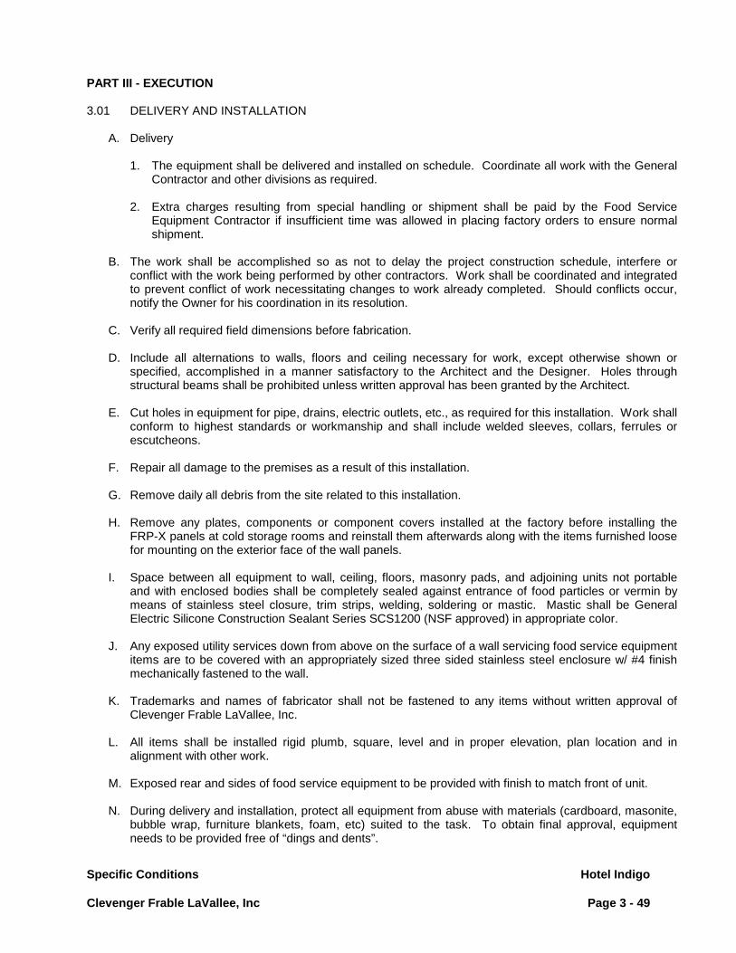
Specific Conditions Hotel Indigo Clevenger Frable LaVallee, Inc Page 3 - 49
PART III - EXECUTION 3.01 DELIVERY AND INSTALLATION
A. Delivery
1. The equipment shall be delivered and installed on schedule. Coordinate all work with the General Contractor and other divisions as required.
2. Extra charges resulting from special handling or shipment shall be paid by the Food Service
Equipment Contractor if insufficient time was allowed in placing factory orders to ensure normal shipment.
B. The work shall be accomplished so as not to delay the project construction schedule, interfere or
conflict with the work being performed by other contractors. Work shall be coordinated and integrated to prevent conflict of work necessitating changes to work already completed. Should conflicts occur, notify the Owner for his coordination in its resolution.
C. Verify all required field dimensions before fabrication. D. Include all alternations to walls, floors and ceiling necessary for work, except otherwise shown or
specified, accomplished in a manner satisfactory to the Architect and the Designer. Holes through structural beams shall be prohibited unless written approval has been granted by the Architect.
E. Cut holes in equipment for pipe, drains, electric outlets, etc., as required for this installation. Work shall
conform to highest standards or workmanship and shall include welded sleeves, collars, ferrules or escutcheons.
F. Repair all damage to the premises as a result of this installation. G. Remove daily all debris from the site related to this installation.
H. Remove any plates, components or component covers installed at the factory before installing the
FRP-X panels at cold storage rooms and reinstall them afterwards along with the items furnished loose for mounting on the exterior face of the wall panels.
I. Space between all equipment to wall, ceiling, floors, masonry pads, and adjoining units not portable
and with enclosed bodies shall be completely sealed against entrance of food particles or vermin by means of stainless steel closure, trim strips, welding, soldering or mastic. Mastic shall be General Electric Silicone Construction Sealant Series SCS1200 (NSF approved) in appropriate color.
J. Any exposed utility services down from above on the surface of a wall servicing food service equipment
items are to be covered with an appropriately sized three sided stainless steel enclosure w/ #4 finish mechanically fastened to the wall.
K. Trademarks and names of fabricator shall not be fastened to any items without written approval of
Clevenger Frable LaVallee, Inc. L. All items shall be installed rigid plumb, square, level and in proper elevation, plan location and in
alignment with other work. M. Exposed rear and sides of food service equipment to be provided with finish to match front of unit. N. During delivery and installation, protect all equipment from abuse with materials (cardboard, masonite,
bubble wrap, furniture blankets, foam, etc) suited to the task. To obtain final approval, equipment needs to be provided free of “dings and dents”.

Specific Conditions Hotel Indigo Clevenger Frable LaVallee, Inc Page 3 - 50
O. Cold Storage Rooms
1. The cold storage rooms shall be delivered and installed on schedule by factory supervised and approved installers. Coordinate the work with the General Contractor and other trades as necessary.
2. Become fully familiar with the job site and the architectural drawings and specifications. Provide
the necessary job site coordination with the various trades to insure job site conditions will meet the requirements of the cold storage rooms.
3. Establish a time schedule with the General Contractor that will insure the job site coordination with
the various trades to insure job site conditions will meet the requirements of the cold storage rooms.
4. All work shall be designed and manufactured to comply with field conditions and fitted with proper
joints and sections. 5. During curing and cleaning of the wearing floors inside the cold storage rooms, the cold storage
room doors shall be left open and the rooms well ventilated to prevent damage to the interior. "Keep Out" signs shall be posted at each open door.
6. After the installation of the cold storage rooms and prior to the installation of the wearing floor and
after the wearing floor has cured, the cold storage room doors are to be closed and locked. 7. Where the floor is depressed or floorless, walls shall be anchored to the building floor with a
concealed 18 gauge galvanized steel floor track with drive pins 2'-0" on center and sealed at interior and exterior edges with a bead of sealant.
P. Refrigeration Systems
1. Refrigeration systems and connecting piping shall be installed as indicated in contract documents in a manner that provides complete and operational systems and eliminates any noise and vibration being transmitted to any part of the building.
2. Piping shall be installed to permit normal inspection, service, removal of the condensing units and
their components and view of sight glasses and allow expansion and contraction without damage to the system.
3. Extreme care shall be taken to keep the entire system clean and dry. 4. Nitrogen gas shall flow through piping being welded to prevent scaling. The Owner or Designer
shall have the option of cutting a maximum of three (3) welded fittings to inspect for the proper use of nitrogen. Food Service Equipment Contractor shall replace fittings at his cost where scaling is present.
5. Suction and discharge line vibration eliminators shall be furnished and installed parallel to the
compressor shaft and secured at outlet end as required to eliminate vibration in rigid piping. 6. All refrigeration lines shall be factory extended to one end of the compressor rack in a neat and
orderly manner and shall be supported and anchored with "Unistrut" or equal clamps and channels. Ends of lines shall be capped against contamination.
7. Compressors and all accessories on the compressor rack shall be factory mounted and pre-wired
to a main circuit breaker control panel with individual circuit breakers wired to a main breaker disconnect requiring a single power connection. All wiring shall be run inside a code approved raceway.

Specific Conditions Hotel Indigo Clevenger Frable LaVallee, Inc Page 3 - 51
8. Condenser water supply and return header shall be factory pre-plumbed using hard copper tubing with shut-off valves for supply and return for each.
a. Provisions shall be provided for connection to city water for emergency use. b. Verify water system pressure and provide all necessary components to insure proper operation
of the water cooled system and the return of the water to the recirculating system.
9. If, in the opinion of the Food Service Equipment Contractor, additional ventilation is required to ensure correct operating temperatures, he shall so state in a letter to Owner and/or Designer for evaluation and decision before installation.
Q. Refrigeration System Instructions and Identification
1. Food Service Equipment Contractor shall at each component of every system identify it with the
letter/number shown on the Refrigeration Schedule. The identification shall be with black paint, decal, or other approved permanent method. Plastic tape labels are unacceptable. Identification shall be in an easily seen location.
R. Refrigeration Piping Testing
1. Notify Owner and/or Designer in advance when a test is being made and ready for inspection. 2. Each system shall be pressure tested for leaks. All valves shall be fully open during the test. 3. Tests are to be accomplished as follows:
a. Charge the systems with refrigerant through the port of liquid shut off valves of the receivers to
a pressure of 10 to 20 p.s.i. b. Add dry nitrogen, the supply of which shall be equipped with a pressure regulating valve to
provide the specified pressure. c. Carefully test all joints for leaks using either a Halide torch or an electronic Halogen leak
detector.
4. The Owner or Designer shall approve all tests. 5. Precautions shall be taken to disconnect the low pressure controls for protection of the bellows
during testing.
S. Refrigeration System Evacuation
1. Advise Owner and/or Designer when the evacuation of the system is to start, so the procedures can be checked.
2. Evacuation shall be with an Airserco, Stroke KC8R or Robinaire, 150021 vacuum pump with an
indicating gauge registering pressure in microns. Pump shall be connected to the system with a 5/8" O.D. line or larger.
3. Evacuate both high and low sides to 500 microns. Break the vacuum with refrigerant to 0 p.s.i.
evacuate the high and low sides below 500 microns; Break the vacuum with refrigerant; evacuate high and low sides to 100 microns; and then break vacuum to 0 p.s.i. with the refrigerant to be used in the system.

Specific Conditions Hotel Indigo Clevenger Frable LaVallee, Inc Page 3 - 52
T. Foodservice Equipment Contractor to confirm installation requirements with food service equipment manufacturer where equipment units penetrate the counter top [stainless steel, plastic laminate, solid surface, stone (natural & man-made)].
Foodservice equipment Contractor to coordinate installation requirements suggested by the
manufacturer with the Millwork Contractor. 3.02 START-UP & DEMONSTRATION
A. All equipment under this section shall be cleaned and ready for operation at the time the food service area is being turned over to the Owner.
B. Provide a factory authorized service technician to be present for equipment start-up. He shall lubricate
and put into proper operation all equipment. E. Manufacturer’s representatives, in concert with the Foodservice Equipment Contractor’s representative
will instruct the Owner's employees in the proper use and maintenance of all items in this contract.
D. Factory supervision of installation is required for the following items: utility distribution systems, water wash exhaust hoods, refrigeration rack systems, flight type dishmachines, pulper systems, conveyorized soiled dishtable assemblies, cook-chill systems and their major components, cooking suites, potwashing machines and conveyorized tray make-up systems.
E. At the completion of the start - up procedure, the Food Service Equipment Contractor will provide
documentation to the Owner which is prepared by the service agent indicating that the equipment was put into operation per the manufacturer’s recommendations. Any equipment not installed per the manufacturer’s recommendations will be documented and called to the Owner’s attention at the time of start –up.
C. Refrigeration System Start-up
1. Charge each system with the refrigerant specified in the Refrigeration Schedule. 2. All systems and controls shall be set and checked for proper operation at temperatures specified in
the Refrigeration Schedule. 3. Check compressors for proper oil level. Refrigerant oil shall be Suniso 3G, inhibited only, delivered
to job site in sealed containers. Oil shall be added to the system to maintain 1/4" to 1/2" sight glass.
4. Check all electrical circuits by Division 26 for compliance with the manufacturer's specifications.
Division 26 shall make corrections to his wiring as required. The Food Service Equipment Contractor shall be responsible for corrections in his wiring and/or components as required.
5. The manufacturer's requirements for lubrication shall be checked and followed before the
operation of fan and pump motors, and/or associated equipment. 6. Furnish and install, where directed by the Owner, copies of the Refrigeration Schedule and
Refrigeration Floor Plan, framed with a glass covering. The Refrigeration Floor Plan shall show the location of all EPR, CTR, and/or CDA valves, solenoid valves, and other controls for easy location and services.
7. Provide a set of "As Built Drawings" to Owner upon completing the installation. Drawings shall
include refrigeration line runs and wiring diagrams. Drawings shall be submitted in the form of reproducible sepias.

Specific Conditions Hotel Indigo Clevenger Frable LaVallee, Inc Page 3 - 53
D. Review the refrigeration systems, operation, maintenance, emergency procedures, and proper service procedures with the Owner's Engineering Staff. Provide a competent serviceman who shall remain for a minimum of eight (8) hours during the first day of operations.
E. Where concrete has been poured inside a low temperature cold storage room it shall be allowed to
cure twenty-eight (28) days, minimum seven (7) days before starting the refrigeration system. After the curing period the temperature shall be brought down in regulated stages. The temperature shall be brought down as follows: to 40oF. ( 5oC.) held twenty-four (24) hours; to 20oF. (-6o
C.) held twenty-four (24) hours; and then to specified temperature.
F. During start-up provide all required instruction for operation and maintenance of equipment, after one year guarantee period.
G. The fire suppression system shall be tested for the authorities in the Owner's presence. Certificates
shall be obtained and provided to the Owner from the authorities and from the Fire Insurance Rating Bureau.
H. After installation and hook-up, verify air volumes at each exhaust and make-up air duct. A report shall
be submitted to the Owner of all readings. All incorrect air volumes shall be rechecked after adjustment.
3.03 MAINTENANCE SCHEDULE
A. Provide final operation warranty and service inspections thirty (30) days before warranty expiration. Any service or repair requirements shall be performed before the end of the warranty period.
B. Copies of all warranty service calls and inspection reports shall be mailed to the Owner and building
operations engineer. C. The Owner may call an outside company at the expense of the Food Service Equipment Contractor, if
the Food Service Equipment Contractor does not arrive within four (4) hours of the time called in response to an emergency call.

Specific Conditions Hotel Indigo Clevenger Frable LaVallee, Inc Page 3 - 54
PART IV - EQUIPMENT 4.01 REGULAR MANUFACTURED EQUIPMENT
A. Provide equipment with standard finishes and accessories unless specifically deleted or superseded by the contract documents.
4.02 FABRICATED EQUIPMENT
A. Provide arrangement and configuration as shown on plans, elevations and standard detail drawings. 4.03 BID QUOTATION SUMMARY FORM 4.04 FOOD SERVICE EQUIPMENT SPECIFICATIONS

Bid Quotation Summary Form
Clevenger Frable LaVallee, Inc.
Hotel Indigo
Page 4 - 1
Bid Quotation Summary
Subtotal Equipment
Delivery
Installation
Taxes
Grand Total
Performance Bond
FSE Contractor to Furnish the names of Sub-Contractors:
Stainless Steel Fabricator
Millwork Fabricator N/A
Refrigeration Contractor
Installer
We Acknowledge Addendum(s) , Datedthe above bid is in Accordance with the Bid Documents, Except as Noted.
Firm
Signature
Print Name
Date
The Undersigned Acknowledges That They Have Read and Understand the Instructions to Bidders, General Conditions and Specific Conditions and, If The Successful Bidder, Will Fully Comply With All Articles and Sections Contained Therein.
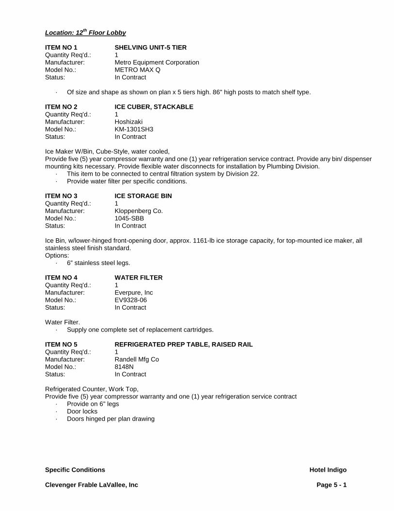
Specific Conditions Hotel Indigo
Clevenger Frable LaVallee, Inc Page 5 - 1
Location: 12th Floor Lobby ITEM NO 1 SHELVING UNIT-5 TIER Quantity Req'd.: 1 Manufacturer: Metro Equipment Corporation Model No.: METRO MAX Q Status: In Contract
· Of size and shape as shown on plan x 5 tiers high. 86" high posts to match shelf type. ITEM NO 2 ICE CUBER, STACKABLE Quantity Req'd.: 1 Manufacturer: Hoshizaki Model No.: KM-1301SH3 Status: In Contract Ice Maker W/Bin, Cube-Style, water cooled, Provide five (5) year compressor warranty and one (1) year refrigeration service contract. Provide any bin/ dispenser mounting kits necessary. Provide flexible water disconnects for installation by Plumbing Division.
· This item to be connected to central filtration system by Division 22. · Provide water filter per specific conditions.
ITEM NO 3 ICE STORAGE BIN Quantity Req'd.: 1 Manufacturer: Kloppenberg Co. Model No.: 1045-SBB Status: In Contract Ice Bin, w/lower-hinged front-opening door, approx. 1161-lb ice storage capacity, for top-mounted ice maker, all stainless steel finish standard. Options:
· 6” stainless steel legs. ITEM NO 4 WATER FILTER Quantity Req'd.: 1 Manufacturer: Everpure, Inc Model No.: EV9328-06 Status: In Contract Water Filter.
· Supply one complete set of replacement cartridges. ITEM NO 5 REFRIGERATED PREP TABLE, RAISED RAIL Quantity Req'd.: 1 Manufacturer: Randell Mfg Co Model No.: 8148N Status: In Contract Refrigerated Counter, Work Top, Provide five (5) year compressor warranty and one (1) year refrigeration service contract
· Provide on 6" legs · Door locks · Doors hinged per plan drawing

Specific Conditions Hotel Indigo
Clevenger Frable LaVallee, Inc Page 5 - 2
ITEM NO 6 WALL SHELF-2 TIER Quantity Req'd.: 1 Manufacturer: Custom Fabricated Assembly Model No.: Custom-Fabrication Status: In Contract Unit to be of size and shape as shown on plan per detail C-1-2 with the following requirements:
· Two-tier unit, first tier (lower shelf) to be 12" wide, second tier (upper) to be 15" wide. ITEM NO 7 REFRI. COMPRESSOR RACK Quantity Req'd.: 1 Manufacturer: Kairak Model No.: KIR-6S Status: In Contract F.S.E.C. to provide the necessary refrigeration lines required to operate and maintain the refrigeration system for Item’s, 51, 52, 53, 54, and future bar equip on 12th floor. Water cooled. F.S.E.C. to coordinate with the electrical/ plumbing contractor to provide a complete and operable refrigeration system. Provide start-up, five (5) year compressor warranty and one (1) year refrigeration service contract. Division 26 to wire to safety disconnect switch.
· See Architectural plan for location. · Provide refrigeration lines of length and diameter to suit this application. · Provide water regulating valve suitable for 45 - 55 degree condensing water temperature. · Provide with vibration isolators. · Food Service Equipment Contractor to provide complete and operable system
ITEM NO 8 FLOOR TROUGH Quantity Req'd.: 1 Manufacturer: IMC/Teddy Model No.: SFT Status: In Contract Unit of size, shape and location shown on plan.
· Grating to be anti-slip (top & bottom), stainless steel. · Shallow floor trough, 2" deep. · Seepage flange and "weep" holes (for above grade application only).
This item to be set and installed by General Contractor. Quarry tile floor finish to be etched, if required, prior to setting food service equipment in place. Provide grating sections of equal size not to exceed 20" long. Removal of grating to be unobstructed by adjacent equipment. Provide shop drawings of size and scale outlined in specific conditions. Coordinate structural conditions and floor penetrations with General Contractor. Fabricate trough depth and connections accordingly.

Specific Conditions Hotel Indigo
Clevenger Frable LaVallee, Inc Page 5 - 3
ITEM NO 9 EXHAUST VENTILATOR, WALL-MOUNTED Quantity Req'd.: 1 Manufacturer: Captive Aire Model No.: 5430AM-ND-2 Status: In Contract Exhaust Ventilator, island type canopy, exhaust only, high velocity extraction, all stainless steel construction. The model ND-2 is an exhaust only canopy hood rated for all types of cooking equipment. The hood shall have the size, shape and performance specified on drawings. Construction shall be type 430 stainless steel with a #3 or #4 polish where exposed. Individual component construction shall be determined by the manufacturer and ETL. Construction shall be dependent on the structural application to minimize distortion and other defects. All seams, joints and penetrations of the hood enclosure to the lower outermost perimeter that directs and captures grease-laden vapor and exhaust gases shall have a liquid-tight continuous external weld in accordance with NFPA 96. Hood shall be wall type with a minimum of four connections for hanger rods. Corner hanging angles have a 5/8" x 1-1/2" slot pre-punched at the factory, allowing hanging rods to be used for quick and safe installation. Ventilator shall be furnished with U.L. classified high efficiency stainless steel baffle filters, supplied in size and quantity as required by ventilator. The filters shall extend the full length of the hood and the filler panels shall not be more than 6" in width. The hood manufacturer shall supply complete computer generated submittal drawings including hood sections view(s) and hood plan view(s). These drawings must be available to the engineer, architect and owner for their use in construction, operation and maintenance. Exhaust duct collar to be 4" high with 1" flange. Duct sizes, CFM and static pressure requirements shall be as shown on drawings. Static pressure requirements shall be precise and accurate; air velocity and volume information shall be accurate within 1-ft increments along the length of the ventilator. U.L. incandescent light fixtures and globes shall be installed and pre-wired to a junction box. The light fixtures shall be installed with a maximum of 4’0" spacing on center and allow up to a 100 watt standard light bulb. The hood shall have:
· A double wall insulated front to eliminate condensation and increase rigidity. The insulation shall have a flexural modulus of 475 EI, meet UL 181 requirements and be in accordance with NFPA 90A and 90B.
· An integral front baffle to direct grease laden vapors toward the exhaust filter bank. · A built-in wiring chase provided for outlets and electrical controls on the hood face and shall not penetrate the
capture area or require an external chaseway. · Removable grease cup for easy cleaning.
The hood shall be ETL Listed as "Exhaust Hood Without Exhaust Damper", ETL Sanitation Listed and built in accordance with NFPA 96. The hood shall be listed for 450°F cooking surfaces at 150 CFM/ft, 600°F cooking surfaces at 200 CFM/ft, and 700°F cooking surfaces at 250 CFM/ft. The hood shall be ETL Listed as "Exhaust Hood Without Exhaust Damper". Optional Features
· Utility Cabinet · Back Supply Plenum · End Panels · Captrate Combo®, Captrate Solo®, stainless steel baffle, aluminum baffle, and high velocity cartridge filters · Enclosure Panels
The Electrical Package, typically FP, is designed to thermostatically activate the exhaust fans for an exhaust hood whenever elevated temperatures are sensed in the exhaust system. This option will meet the requirements of IMC 507.2.1.1 by providing a thermostat(s) mounted in the duct or hood riser to sense increased exhaust temperatures. Controls shall be listed by ETL (UL 508A). The control enclosure shall be NEMA 1 rated and listed for installation inside of the exhaust hood utility cabinet. The control enclosure may be constructed of stainless steel or painted steel. Temperature probes(s) located in the duct riser shall be constructed of Stainless Steel. A room temperature sensor is also provided for field installation in the kitchen space in order to start the fan(s) based on the temperature differential between the room and the exhaust air in the duct, rather than fixed set-points.

Specific Conditions Hotel Indigo
Clevenger Frable LaVallee, Inc Page 5 - 4
The system is factory pre-set to activate the fans at 10 deg F° above the room temperature. Once the duct temperature reaches the activation point, the exhaust fans will be activated. The controls also provide hysteresis to prevent cycling of the fans after the cooking appliances have been turned off and the heat in the exhaust system is reduced. The hysteresis is factory set 2 degrees and will keep the exhaust running until the temperature falls 2 degrees below the activation set point. A hysteresis timer also exists to keep the fans running for at least 30 min after being activated by the temperature rise. The activation and hysteresis settings may be field adjusted on the board LCD interface located inside the control enclosure to meet application needs. The panel is factory configured to shut down supply fans, turn on the exhaust fans and turn off the hood lights in a fire condition. ITEM NO 10 FIRE SUPPRESSION SYSTEM Quantity Req'd.: 1 Manufacturer: Ansul Model No.: R-102 Status: In Contract Fire Suppression System, dry chemical system, w/mechanically operated control head, wall-mounted tank assembly, chrome-plated fittings and pipe. Fire protection system to be provided and installed by FSE Contractor. System to be Ansul R102 system, wet chemical with the following specifications:
· Wet chemical suppressant. · System U.L. Listed, installed in accordance with manufacturer's recommendations, and Comply with NFPA
13 and local codes. · System to be pre-piped and fusible link detection incorporated with ventilator sections by ventilator
manufacturer at time of construction. · Wherever possible, system piping shall be unexposed. Exposed piping, conduit and nozzles shall be smooth
chrome-plated or stainless steel. · Fusible link assemblies shall be unexposed within the ventilator bodies or within enclosed boxes recessed
into ventilator roof. · System shall be shipped complete with tanks, remote manual release. · Cylinders and controls shall be mounted on wall where shown on plan at an accessible height that will not
conflict with equipment below. Mount tight to underside of finished ceiling. · Mechanically activated gas shut off valves furnished by the FSE Contractor and installed by the Plumbing
Contractor. · Coordination and cabling to valve by FSE Contractor. · Shunt trip type breaker disconnect provided and installed by the Electrical Division. · FSE Contractor to coordinate shunt trip breaker requirements with the Electrical Contractor. · System to provide plenum and duct collar protection and surface protection for equipment underneath Item
9, Exhaust Hood. · FSE Contractor will be required to obtain all permits and arrange for system inspection and testing to achieve
an approved operating system. Remote pull station:
· Fire Protection System remote manual activation stations are to be flush wall-mounted, with the cabling conduit recessed within the wall.
· Remote pull stations are to be located along pathways between the protected equipment and area exits, and in accord with any governing local code requirements. FSE Contractor to confirm placement of remote fire pulls w/ Fire Suppression System Subcontractor and reflect code compliant placement on dimensioned rough-in plans.
· FSE Contractor shall coordinate the efforts between the Fire Protection System subcontractor, any other trades, and with local code enforcement officials, as may be necessary to comply with local codes.
· If the FSE contractor determines that, for any reason, the flush mounting of the remote fire pulls is not possible an appropriate and timely “Inability to Comply” statement must be furnished to CFL for their review and response.

Specific Conditions Hotel Indigo
Clevenger Frable LaVallee, Inc Page 5 - 5
ITEM NO 11 HAND SINK Quantity Req'd.: 2 Manufacturer: Eagle Model No.: HSAN-10-F Status: In Contract Hand Sink, wall model
· Heavy duty gooseneck faucet w/wrist handles. · End splash, left add suffix "L" to model number. · Soap and towel dispenser, wall mounted.
ITEM NO 12 COMBI OVEN, WARMING OVEN Quantity Req'd.: 1 Manufacturer: UNOX Model No.: XAV 805 P 208 Status: In Contract
· Door hinged right. · (8) wire racks · (2) Chicken S/S Grid · Rotor.Klean Washing Kit · Safety door opening kit. · Shower kit.
ITEM NO 13 WALL FLASHING, STAINLESS STEEL Quantity Req'd.: 1 Manufacturer: Custom Fabricated Assembly Model No.: Custom-Fabrication Status: In Contract Provide 20 ga. stainless steel wall flashing, approximately ' per detail C-2-11. Stainless steel flashing to extend from floor or top of wall tile base to underside of Item 9, Exhaust Hood. Refer to the “Approved Fabricators” list for alternate manufacturers. Pricing from the specified manufacturer to be included in the base bid. Pricing from alternate manufacturers (from approved fabricators list) to be itemized and quoted on a separate form attached to the primary bid. Pricing from substitute fabricators (not on the approved list) to be itemized and on a separate form attached to the primary bid stating manufacturer and including illustrations, specifications and an itemization of all differences at the time of bid. ITEM NO 14 RANGE, 6-BURNER, MODULAR Quantity Req'd.: 1 Manufacturer: Jade Range Model No.: JMRH-6 Status: In Contract Range, 6-Burner.
· 3/4” rear connection. · Provide flexible quick disconnect per specific conditions. · Inter-connecting gas lines to salamander above.
ITEM NO 15 REFRIGERATED BASE Quantity Req'd.: 1 Manufacturer: Jade Range Model No.: JRLH-04S-T-72 Status: In Contract Refrigerated Base.
· 6” casters, front locking (5” diameter wheel) · Padlock Assembly

Specific Conditions Hotel Indigo
Clevenger Frable LaVallee, Inc Page 5 - 6
ITEM NO 16 RANGE, MATCH CHAR BROILER Quantity Req'd.: 1 Manufacturer: Jade Range Model No.: JMRH-36B Status: In Contract Range, Plancha Top. .
· 3/4” rear connection. · Double high backsplash Stainless steel. · Flexible gas disconnect w/ restraining device per specific conditions
ITEM NO 17 SALAMANDER BROILER, RANGE MOUNT Quantity Req'd.: 1 Manufacturer: Jade Range Model No.: JSB-36RMT Status: In Contract Salamander Broiler, Range Mount. Salamander to be mounted and pre-piped at factory with Item 14, Range ITEM NO 18 TABLE, ISLAND STYLE Quantity Req'd.: 1 Manufacturer: Custom Fabricated Assembly Model No.: Custom-Fabrication Status: In Contract Table, open front, details as shown, Unit to be of size and shape as shown on plan x 52” high Type “A” edge, Provide with the following: Table Top
· Extra high to allow for combi under. . Table Base
· Open base to floor to accommodate Item 12. Base/ Legs Detail
· Provide unit with front to back cross rails only. Refer to the “Approved Fabricators” list for alternate manufacturers. Pricing from the specified manufacturer to be included in the base bid. Pricing from alternate manufacturers (from approved fabricators list) to be itemized and quoted on a separate form attached to the primary bid. Pricing from substitute fabricators (not on the approved list) to be itemized and on a separate form attached to the primary bid stating manufacturer and including illustrations, specifications and an itemization of all differences at the time of bid. ITEM NO 19 PIZZA OVEN, TWO DECK, COUNTERTOP Quantity Req'd.: 1 Manufacturer: Bakers Pride Model No.: DP2 Status: In Contract
· Oven Deck Brush · 208V, 3 Phase

Specific Conditions Hotel Indigo
Clevenger Frable LaVallee, Inc Page 5 - 7
ITEM NO 20 FRYER, DEEP FAT Quantity Req'd.: 2 Manufacturer: Pitco, Inc. Model No.: SG14 Status: In Contract Fryer, Deep Fat.
· Twin baskets. · Standard height riser.
ITEM NO 21 WALL SHELF Quantity Req'd.: 1 Manufacturer: Custom Fabricated Assembly Model No.: Custom-Fabrication Status: In Contract Unit to be of size and shape as shown on plan per detail C-1-2 with the following requirements: Two-tier unit, first tier (lower shelf) to be 12" wide, second tier (upper) to be 15" wide. ITEM NO 22 REFRIGERATED DRAWER, FREEZER Quantity Req'd.: 1 Manufacturer: Randell Mfg Co Model No.: FX-1UC Status: In Contract Refrigerated Cabinet, Undercounter, Provide five (5) year compressor warranty and one (1) year refrigeration service contract. ITEM NO 23 COUNTER W/2 SINKS Quantity Req'd.: 1 Manufacturer: Custom Fabricated Assembly Model No.: Custom-Fabrication Status: In Contract Counter, open front cabinet base, details as shown, Unit to be of size and shape as shown on plan x 36” high w/ 6” splash per detail C-1-1A Type “A” edge, C-1-1B backsplash and C-7-1. (Define) end splashes as shown on plan. Provide with the following: Table Top
· Notch for column(s) where shown on plan. · (2) 16" x 20" x 12" deep sink w/ Type 5 faucet and Type 1 waste. · Removable sink cover(s)per detail C-8-17 - Flush Mount. · Cut outs to accommodate item’s 46, and 47.
Table Base · Open base to floor to accommodate Item 22.
Base/ Legs Detail · Provide unit with full length under shelf to left of the refrig .
Refer to the “Approved Fabricators” list for alternate manufacturers. Pricing from the specified manufacturer to be included in the base bid. Pricing from alternate manufacturers (from approved fabricators list) to be itemized and quoted on a separate form attached to the primary bid. Pricing from substitute fabricators (not on the approved list) to be itemized and on a separate form attached to the primary bid stating manufacturer and including illustrations, specifications and an itemization of all differences at the time of bid.

Specific Conditions Hotel Indigo
Clevenger Frable LaVallee, Inc Page 5 - 8
ITEM NO 24 POS PRINTER Quantity Req'd.: 1 Manufacturer: By Owner Model No.: POS-P Status: By Owner/Operator This item is not in contract. The specification is for reference only. The item is shown on the drawing for informational purposes and generally represents the size/ capacity of unit to be provided by the Owner. ITEM NO 25 PLATE CABINET Quantity Req'd.: 1 Manufacturer: Custom Fabricated Assembly Model No.: Custom-Fabrication Status: In Contract Unit to be of size and shape as shown on plan x 38” high w/ Type “A” edge, Provide with the following:
· Adjustable intermediate shelves, (2) · Provide tray lock with chefs counter. · Utility chase to handle utilities for the Chefs counter equipment. · Refer to Item # 28, Chef’s Counter for fabrication details
Refer to the “Approved Fabricators” list for alternate manufacturers. Pricing from the specified manufacturer to be included in the base bid. Pricing from alternate manufacturers (from approved fabricators list) to be itemized and quoted on a separate form attached to the primary bid. Pricing from substitute fabricators (not on the approved list) to be itemized and on a separate form attached to the primary bid stating manufacturer and including illustrations, specifications and an itemization of all differences at the time of bid. ITEM NO 26 REFRIGERATED PREP TABLE, RAISED RAIL Quantity Req'd.: 1 Manufacturer: Randell Mfg Co Model No.: 8148N Status: In Contract Refrigerated Counter, Work Top, Provide five (5) year compressor warranty and one (1) year refrigeration service contract
· Provide on 6" legs · Door locks · Doors hinged per plan drawing
ITEM NO 27 DISH RACK DOLLY Quantity Req'd.: LOT Manufacturer: Metro Equip Model No.: D2020N Status: By Owner Dolly, Rack, This item is not in contract. The specification is for reference only. The item is shown on the drawing for informational purposes and generally represents the size/ capacity of unit to be provided by the Owner.
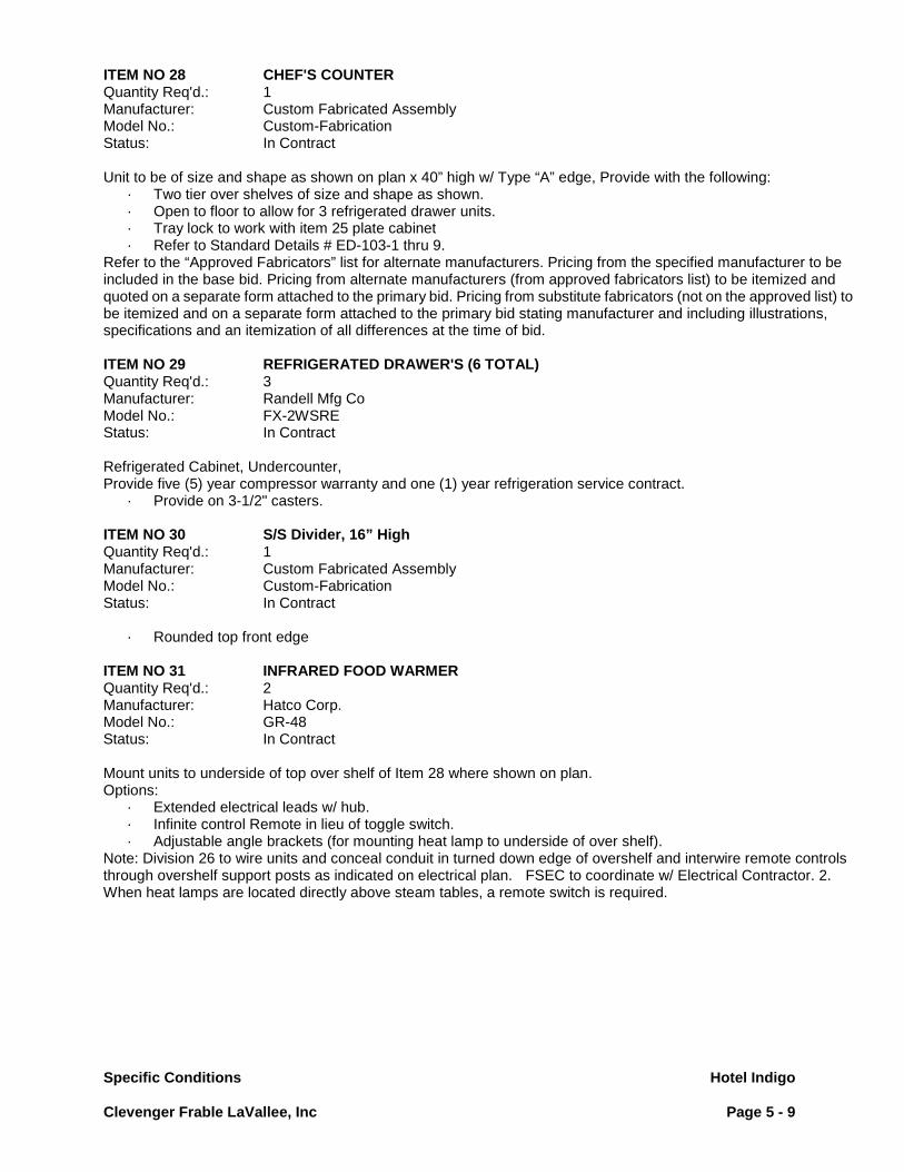
Specific Conditions Hotel Indigo
Clevenger Frable LaVallee, Inc Page 5 - 9
ITEM NO 28 CHEF'S COUNTER Quantity Req'd.: 1 Manufacturer: Custom Fabricated Assembly Model No.: Custom-Fabrication Status: In Contract Unit to be of size and shape as shown on plan x 40” high w/ Type “A” edge, Provide with the following:
· Two tier over shelves of size and shape as shown. · Open to floor to allow for 3 refrigerated drawer units. · Tray lock to work with item 25 plate cabinet · Refer to Standard Details # ED-103-1 thru 9.
Refer to the “Approved Fabricators” list for alternate manufacturers. Pricing from the specified manufacturer to be included in the base bid. Pricing from alternate manufacturers (from approved fabricators list) to be itemized and quoted on a separate form attached to the primary bid. Pricing from substitute fabricators (not on the approved list) to be itemized and on a separate form attached to the primary bid stating manufacturer and including illustrations, specifications and an itemization of all differences at the time of bid. ITEM NO 29 REFRIGERATED DRAWER'S (6 TOTAL) Quantity Req'd.: 3 Manufacturer: Randell Mfg Co Model No.: FX-2WSRE Status: In Contract Refrigerated Cabinet, Undercounter, Provide five (5) year compressor warranty and one (1) year refrigeration service contract.
· Provide on 3-1/2" casters. ITEM NO 30 S/S Divider, 16” High Quantity Req'd.: 1 Manufacturer: Custom Fabricated Assembly Model No.: Custom-Fabrication Status: In Contract
· Rounded top front edge ITEM NO 31 INFRARED FOOD WARMER Quantity Req'd.: 2 Manufacturer: Hatco Corp. Model No.: GR-48 Status: In Contract Mount units to underside of top over shelf of Item 28 where shown on plan. Options:
· Extended electrical leads w/ hub. · Infinite control Remote in lieu of toggle switch. · Adjustable angle brackets (for mounting heat lamp to underside of over shelf).
Note: Division 26 to wire units and conceal conduit in turned down edge of overshelf and interwire remote controls through overshelf support posts as indicated on electrical plan. FSEC to coordinate w/ Electrical Contractor. 2. When heat lamps are located directly above steam tables, a remote switch is required.

Specific Conditions Hotel Indigo
Clevenger Frable LaVallee, Inc Page 5 - 10
ITEM NO 32 CONVECTION MICROWAVE Quantity Req'd.: 1 Manufacturer: Merrychef Model No.: EIKON E4S Status: In Contract Convection Microwave
· EZ-Touch control panel. · Solid stainless steel door. · Operation Manual/Cleaning Instructions · Tray Handle and oven Paddle w/protector
ITEM NO 33 MOP SINK STORAGE CABINET Quantity Req'd.: 1 Manufacturer: Eagle Model No.: F1916-VSCS Status: In Contract Mop Sink, floor mounted
· Mop holder, 2. · Service faucet. · 36" long hose w/ faucet connection at one end.
ITEM NO 34 WALL SHELF Quantity Req'd.: 1 Manufacturer: Custom Fabricated Assembly Model No.: Custom-Fabrication Status: In Contract Unit to be of size and shape as shown on plan per detail C-1-2 with the following requirements:
· Two-tier unit, first tier (lower shelf) to be 12" wide, second tier (upper) to be 15" wide. ITEM NO 35 DISHTABLE, CLEAN Quantity Req'd.: 1 Manufacturer: Custom Fabricated Assembly Model No.: Custom-Fabrication Status: In Contract Dishtable, Clean, stainless steel top, double-ell, right-to-left, 10" high splash at walls, 3" high rolled rims, stainless steel open frame pipe base, with side and rear crossrails. Unit to be of size and shape as shown on plan x 34" high to drainboard level with 10" high splash per details C-1-1A Type "D" edge, C-1-1B backsplash and C-8-1. Provide with the following:
· Open base type table, no undershelf. · Front to back and rear crossrails only. · Provide three compartment sink w/ 10" splash and sinks of size and shape as shown on plan x 14" deep w/
rotary wastes per detail C-8-5, overflow per detail C-8-8 w/ seamless flush front construction, two (2) Type 2 faucets, and open base type table, no undershelves.
Refer to the “Approved Fabricators” list for alternate manufacturers. Pricing from the specified manufacturer to be included in the base bid. Pricing from alternate manufacturers (from approved fabricators list) to be itemized and quoted on a separate form attached to the primary bid. Pricing from substitute fabricators (not on the approved list) to be itemized and on a separate form attached to the primary bid stating manufacturer and including illustrations, specifications and an itemization of all differences at the time of bid.
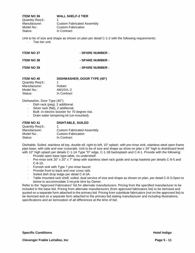
Specific Conditions Hotel Indigo
Clevenger Frable LaVallee, Inc Page 5 - 11
ITEM NO 36 WALL SHELF-2 TIER Quantity Req'd.: 1 Manufacturer: Custom Fabricated Assembly Model No.: Custom-Fabrication Status: In Contract Unit to be of size and shape as shown on plan per detail C-1-2 with the following requirements:
· Two tier unit. ITEM NO 37 - SPARE NUMBER - ITEM NO 38 - SPARE NUMBER - ITEM NO 39 - SPARE NUMBER - ITEM NO 40 DISHWASHER, DOOR TYPE (40°) Quantity Req'd.: 1 Manufacturer: Hobart Model No.: AM15VL-2 Status: In Contract Dishwasher, Door Type (40°).
· Dish rack (peg), 2 additional. · Silver rack (flat), 2 additional. · Built -in electric booster for 70 degree rise. · Drain water tempering kit (un-mounted).
ITEM NO 41 DISHTABLE, SOILED Quantity Req'd.: 1 Manufacturer: Custom Fabricated Assembly Model No.: Custom-Fabrication Status: In Contract Dishtable, Soiled, stainless stl top, double-ell, right-to-left, 10" splash, with pre-rinse sink, stainless steel open frame pipe base, with side and rear crossrails. Unit to be of size and shape as show on plan x 34" high to drainboard level with 10" high splash per details C-1-1A Type "D" edge, C-1-1B backsplash and C-8-1. Provide with the following:
· Provide open base type table, no undershelf. · Pre-rinse sink 20" x 20" x 7" deep with stainless steel rack guide and scrap baskets per details C-8-5 and
C-8-10. · Furnish sink with Type 7 pre-rinse faucet · Provide front to back and rear cross rails · Soiled dish drop ledge per detail C-8-3A. · Table mounted rack shelf, soiled, dual service of size and shape as shown on plan, per detail C-8-3.Open to
below to accommodate 3 recycle bins by Owner. Refer to the “Approved Fabricators” list for alternate manufacturers. Pricing from the specified manufacturer to be included in the base bid. Pricing from alternate manufacturers (from approved fabricators list) to be itemized and quoted on a separate form attached to the primary bid. Pricing from substitute fabricators (not on the approved list) to be itemized and on a separate form attached to the primary bid stating manufacturer and including illustrations, specifications and an itemization of all differences at the time of bid.

Specific Conditions Hotel Indigo
Clevenger Frable LaVallee, Inc Page 5 - 12
ITEM NO 42 RACK SHELF, SOILED, WALL-MOUNTED Quantity Req'd.: 1 Manufacturer: Custom Fabricated Assembly Model No.: Custom-Fabrication Status: In Contract Unit to be of size and shape as shown on plan and per detail C-8-4. Wall mount unit above Item 41, table top. Refer to the “Approved Fabricators” list for alternate manufacturers. Pricing from the specified manufacturer to be included in the base bid. Pricing from alternate manufacturers (from approved fabricators list) to be itemized and quoted on a separate form attached to the primary bid. Pricing from substitute fabricators (not on the approved list) to be itemized and on a separate form attached to the primary bid stating manufacturer and including illustrations, specifications and an itemization of all differences at the time of bid. ITEM NO 43 RECYCLING BIN Quantity Req'd.: 3 Manufacturer: Rubbermaid Model No.: FG352600, GREY Status: By Owner This item is not in contract. The specification is for reference only. The item is shown on the drawing for informational purposes and generally represents the size/ capacity of unit to be provided by the Owner. ITEM NO 44 FLOOR TROUGH Quantity Req'd.: 1 Manufacturer: IMC/Teddy Model No.: CUSTOM Status: In Contract Unit of size, shape and location shown on plan. This item to be set and installed by General Contractor. Quarry tile floor finish to be etched, if required, prior to setting food service equipment in place. Provide grating sections of equal size not to exceed 20" long. Removal of grating to be unobstructed by adjacent equipment. Provide shop drawings of size and scale outlined in specific conditions. Coordinate structural conditions and floor penetrations with General Contractor. Fabricate trough depth and connections accordingly.
· Grating to be anti-slip (top & bottom), stainless steel. · Standard floor trough 4" deep. · Seepage flange and "weep" holes (for above grade application only).
ITEM NO 45 COUNTER BY ARCHITECT Quantity Req'd.: 2 Manufacturer: By Architect Model No.: COUNTER Status: Specified By Architect/Interior Designer This item is not in contract. It is shown on the drawing for informational purposes only and generally represents the size/ capacity of unit to be specified by other design team members and provided by others. Refer to A/E drawings and specifications. ITEM NO 46 DIPPERWELL Quantity Req'd.: 1 Manufacturer: Component Hardware Model No.: K30-1010 Status: In Contract Dipperwell, with faucet, s/s.
· Assembly Complete.
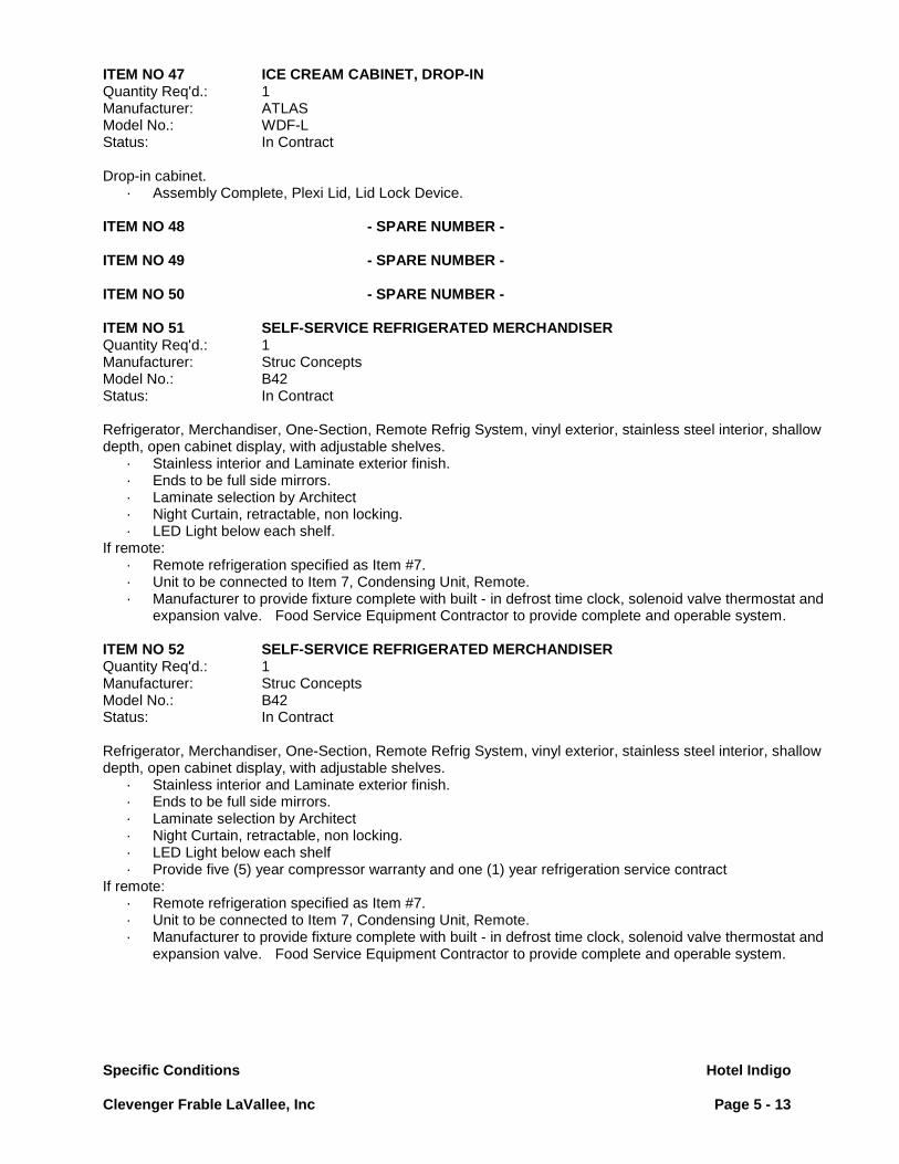
Specific Conditions Hotel Indigo
Clevenger Frable LaVallee, Inc Page 5 - 13
ITEM NO 47 ICE CREAM CABINET, DROP-IN Quantity Req'd.: 1 Manufacturer: ATLAS Model No.: WDF-L Status: In Contract Drop-in cabinet.
· Assembly Complete, Plexi Lid, Lid Lock Device. ITEM NO 48 - SPARE NUMBER - ITEM NO 49 - SPARE NUMBER - ITEM NO 50 - SPARE NUMBER - ITEM NO 51 SELF-SERVICE REFRIGERATED MERCHANDISER Quantity Req'd.: 1 Manufacturer: Struc Concepts Model No.: B42 Status: In Contract Refrigerator, Merchandiser, One-Section, Remote Refrig System, vinyl exterior, stainless steel interior, shallow depth, open cabinet display, with adjustable shelves.
· Stainless interior and Laminate exterior finish. · Ends to be full side mirrors. · Laminate selection by Architect · Night Curtain, retractable, non locking. · LED Light below each shelf.
If remote: · Remote refrigeration specified as Item #7. · Unit to be connected to Item 7, Condensing Unit, Remote. · Manufacturer to provide fixture complete with built - in defrost time clock, solenoid valve thermostat and
expansion valve. Food Service Equipment Contractor to provide complete and operable system. ITEM NO 52 SELF-SERVICE REFRIGERATED MERCHANDISER Quantity Req'd.: 1 Manufacturer: Struc Concepts Model No.: B42 Status: In Contract Refrigerator, Merchandiser, One-Section, Remote Refrig System, vinyl exterior, stainless steel interior, shallow depth, open cabinet display, with adjustable shelves.
· Stainless interior and Laminate exterior finish. · Ends to be full side mirrors. · Laminate selection by Architect · Night Curtain, retractable, non locking. · LED Light below each shelf · Provide five (5) year compressor warranty and one (1) year refrigeration service contract
If remote: · Remote refrigeration specified as Item #7. · Unit to be connected to Item 7, Condensing Unit, Remote. · Manufacturer to provide fixture complete with built - in defrost time clock, solenoid valve thermostat and
expansion valve. Food Service Equipment Contractor to provide complete and operable system.

Specific Conditions Hotel Indigo
Clevenger Frable LaVallee, Inc Page 5 - 14
ITEM NO 53 SELF-SERVICE REFRIGERATED MERCHANDISER Quantity Req'd.: 1 Manufacturer: Struc Concepts Model No.: B42 Status: In Contract Refrigerator, Merchandiser, One-Section, Remote Refrig System, vinyl exterior, stainless steel interior, shallow depth, open cabinet display, with adjustable shelves.
· Stainless interior and Laminate exterior finish. · Ends to be full side mirrors. · Laminate selection by Architect · Night Curtain, retractable, non locking. · LED Light below each shelf · Provide five (5) year compressor warranty and one (1) year refrigeration service contract
If remote: · Remote refrigeration specified as Item #7. · Unit to be connected to Item 7, Condensing Unit, Remote. · Manufacturer to provide fixture complete with built - in defrost time clock, solenoid valve thermostat and
expansion valve. Food Service Equipment Contractor to provide complete and operable system. ITEM NO 54 SELF-SERVICE REFRIGERATED MERCHANDISER Quantity Req'd.: 1 Manufacturer: Struc Concepts Model No.: B42 Status: In Contract Refrigerator, Merchandiser, One-Section, Remote Refrig System, vinyl exterior, stainless steel interior, shallow depth, open cabinet display, with adjustable shelves.
· Stainless interior and Laminate exterior finish. · Ends to be full side mirrors. · Laminate selection by Architect · Night Curtain, retractable, non locking. · LED Light below each shelf · Provide five (5) year compressor warranty and one (1) year refrigeration service contract
If remote: · Remote refrigeration specified as Item #7. · Unit to be connected to Item 7, Condensing Unit, Remote. · Manufacturer to provide fixture complete with built - in defrost time clock, solenoid valve thermostat and
expansion valve. Food Service Equipment Contractor to provide complete and operable system. ITEM NO 55 ESPRESSO MACHINE, W/MILK Quantity Req'd.: 1 Manufacturer: Schaerer Model No.: COFFEE ART TCH IT (040390-00008EUS) Status: In Contract Milk/Espresso Machine, Super automatic, 1 step drink delivery
· F.S.E. Contractor to provide unit with Dormont Model SWIRL water connector hose, appropriately sized, with quick disconnect 2-way coupling per specific conditions.
· Connect to Item 4, Central Water Treatment System.

Specific Conditions Hotel Indigo
Clevenger Frable LaVallee, Inc Page 5 - 15
ITEM NO 56 ESPRESSO MACHINE Quantity Req'd.: 2 Manufacturer: Schaerer Model No.: E6C Status: By Owner Espresso Machine, super-automatic, push-button operation
· F.S.E. Contractor to provide unit with Dormont Model SWIRL water connector hose, appropriately sized, with quick disconnect 2-way coupling per specific conditions
· Connect to Item 4, Central Water Treatment System. ITEM NO 57 - SPARE NUMBER - Location: 15TH FLOOR BARS ITEM NO 1 DISPLAY CASE, REFRIGERATED Quantity Req'd.: 2 Manufacturer: Cntl Refr Corp Model No.: 2RE-SA-SGD Status: In Contract Display Case, Refrigerated, glass front, self-service, with three intermediate shelves, size as shown on drawings, stainless steel exterior, aluminum interior. Manufacturer's standard specifications.
· Two section refrigerator. · Sliding Doors. · Aluminum interior. · Stainless steel exterior. · Doors w/ locks, common keyed. · 6" stainless steel legs with adjustable bullet feet. · Provide five (5) year compressor warranty and one (1) year refrigeration service contract. · Fluorescent lights. · Furnish w/ cord & plug.
ITEM NO 2 SHELVING UNIT Quantity Req'd.: 1 Manufacturer: Metro Equip Model No.: SUPER ERECTA CHROME Status: In Contract Of size and shape as shown on plan x 5 tiers high. 86" high posts to match shelf type. ITEM NO 3 ICE CRUSHER Quantity Req'd.: 1 Manufacturer: Nor-Lake, Inc Model No.: N14CRSS-A Status: In Contract ICE CRUSHER Ice Crusher. 1 extra Ice Bin.

Specific Conditions Hotel Indigo
Clevenger Frable LaVallee, Inc Page 5 - 16
ITEM NO 4 FREEZER, REACH-IN (18-INCHW) Quantity Req'd.: 1 Manufacturer: Cntl Refr Corp Model No.: 1FSE-SA Status: In Contract Freezer, Reach-in, One-Section, Self-Contained Refrigeration System, aluminum interior, stainless steel exterior. Manufacturer's standard specifications.
· One section freezer. · Narrow width, standard depth. · Doors w/ cylinder locks, common keyed. · Provide “1” additional wire shelves. · Heavy duty casters, two locking. · Provide five (5) year compressor warranty and one (1) year refrigeration service contract. · Furnish w/ cord & plug.
ITEM NO 5 FLOOR TROUGH Quantity Req'd.: 1 Manufacturer: IMC/Teddy Model No.: SFT Status: In Contract Unit of size, shape and location shown on plan. This item to be set and installed by General Contractor. Quarry tile floor finish to be etched, if required, prior to setting food service equipment in place. Provide grating sections of equal size not to exceed 20" long. Removal of grating to be unobstructed by adjacent equipment. Provide shop drawings of size and scale outlined in specific conditions. Coordinate structural conditions and floor penetrations with General Contractor. Fabricate trough depth and connections accordingly.
· Grating to be anti-slip (top & bottom), stainless steel. · Shallow floor trough, 4" deep. · Seepage flange and "weep" holes (for above grade application only).
ITEM NO 6 ICE STORAGE BIN Quantity Req'd.: 1 Manufacturer: KOLD-DRAFT Model No.: B400 Status: In Contract Ice Storage Bin.
· 6” stainless steel legs. ITEM NO 7 ICE CUBER Quantity Req'd.: 2 Manufacturer: KOLD-DRAFT Model No.: GT564AK Status: In Contract Ice Cuber
· Provide five (5) year compressor warranty and one (1) year refrigeration service contract. · Provide any bin/ dispenser mounting kits necessary. · Provide flexible water disconnects for installation by Plumbing Division. · This item to be connected to central filtration system by Division 22.
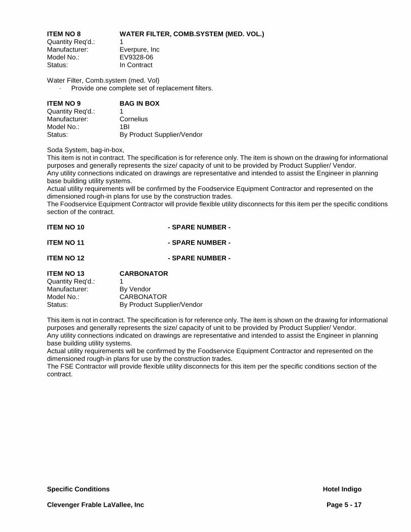
Specific Conditions Hotel Indigo
Clevenger Frable LaVallee, Inc Page 5 - 17
ITEM NO 8 WATER FILTER, COMB.SYSTEM (MED. VOL.) Quantity Req'd.: 1 Manufacturer: Everpure, Inc Model No.: EV9328-06 Status: In Contract Water Filter, Comb.system (med. Vol)
· Provide one complete set of replacement filters. ITEM NO 9 BAG IN BOX Quantity Req'd.: 1 Manufacturer: Cornelius Model No.: 1BI Status: By Product Supplier/Vendor Soda System, bag-in-box, This item is not in contract. The specification is for reference only. The item is shown on the drawing for informational purposes and generally represents the size/ capacity of unit to be provided by Product Supplier/ Vendor. Any utility connections indicated on drawings are representative and intended to assist the Engineer in planning base building utility systems. Actual utility requirements will be confirmed by the Foodservice Equipment Contractor and represented on the dimensioned rough-in plans for use by the construction trades. The Foodservice Equipment Contractor will provide flexible utility disconnects for this item per the specific conditions section of the contract. ITEM NO 10 - SPARE NUMBER - ITEM NO 11 - SPARE NUMBER - ITEM NO 12 - SPARE NUMBER - ITEM NO 13 CARBONATOR Quantity Req'd.: 1 Manufacturer: By Vendor Model No.: CARBONATOR Status: By Product Supplier/Vendor This item is not in contract. The specification is for reference only. The item is shown on the drawing for informational purposes and generally represents the size/ capacity of unit to be provided by Product Supplier/ Vendor. Any utility connections indicated on drawings are representative and intended to assist the Engineer in planning base building utility systems. Actual utility requirements will be confirmed by the Foodservice Equipment Contractor and represented on the dimensioned rough-in plans for use by the construction trades. The FSE Contractor will provide flexible utility disconnects for this item per the specific conditions section of the contract.

Specific Conditions Hotel Indigo
Clevenger Frable LaVallee, Inc Page 5 - 18
ITEM NO 14 CO2 CYLINDER, 50-LBS. Quantity Req'd.: 1 Manufacturer: By Vendor Model No.: CO2-50 Status: By Product Supplier/Vendor Soda System, bag-in-box, This item is not in contract. The specification is for reference only. The item is shown on the drawing for informational purposes and generally represents the size/ capacity of unit to be provided by Product Supplier/ Vendor. Any utility connections indicated on drawings are representative and intended to assist the Engineer in planning base building utility systems. Actual utility requirements will be confirmed by the Foodservice Equipment Contractor and represented on the dimensioned rough-in plans for use by the construction trades. The Foodservice Equipment Contractor will provide flexible utility disconnects for this item per the specific conditions section of the contract. ITEM NO 15 DISH RACK DOLLY Quantity Req'd.: 1 Manufacturer: Metro Equip Model No.: D2020N Status: By Owner Dolly, Rack, This item is not in contract. The specification is for reference only. The item is shown on the drawing for informational purposes and generally represents the size/ capacity of unit to be provided by the Owner. ITEM NO 16 MOP SINK STORAGE CABINET Quantity Req'd.: 1 Manufacturer: Eagle Model No.: F1916-VSCS Status: In Contract Mop Sink, floor mounted
· Mop holder. · Service faucet. · 36" long hose w/ faucet connection at one end.
ITEM NO 17 DISHTABLE ASSEMBLY, UNDERCOUNTER Quantity Req'd.: 1 Manufacturer: Champion Ind Model No.: 1-RDT-R Status: In Contract Dish table Assembly, Under counter Type, Unit to be of size and shape as show on plan.

Specific Conditions Hotel Indigo
Clevenger Frable LaVallee, Inc Page 5 - 19
ITEM NO 18 DISHWASHER, UNDERCOUNTER Quantity Req'd.: 1 Manufacturer: Champion Ind Model No.: UH-200B(70) Status: In Contract Dishwasher, Undercounter.
· Dish rack (peg), additional · Silver rack (flat), additional · Built in electric booster for 70 degree rise. · Detergent pump (factory installed). · Rinse aid pump (factory installed).
ITEM NO 19 - SPARE NUMBER - ITEM NO 20 - SPARE NUMBER - ITEM NO 21 - SPARE NUMBER - ITEM NO 22 RACK SHELF, CLEAN, WALL-MOUNTED Quantity Req'd.: 1 Manufacturer: Custom Fabricated Assembly Model No.: Custom-Fabrication Status: In Contract Unit to be of size and shape as shown on plan constructed similar to C-1-7. Wall mount unit 30" clear to underside above Item 17, Dish table. Refer to the “Approved Fabricators” list for alternate manufacturers. Pricing from the specified manufacturer to be included in the base bid. Pricing from alternate manufacturers (from approved fabricators list) to be itemized and quoted on a separate form attached to the primary bid. Pricing from substitute fabricators (not on the approved list) to be itemized and on a separate form attached to the primary bid stating manufacturer and including illustrations, specifications and an itemization of all differences at the time of bid. ITEM NO 23 BAR DIE & TOP Quantity Req'd.: 1 Manufacturer: By Architect Model No.: BAR DIE Status: Specified By Architect/Interior Designer This item is not in contract. It is shown on the drawing for informational purposes only and generally represents the size/ capacity of unit to be specified by other design team members and provided by others. Refer to A/E drawings and specifications. ITEM NO 24 COUNTER BY ARCHITECT Quantity Req'd.: 1 Manufacturer: By Architect Model No.: COUNTER Status: Specified By Architect/Interior Designer This item is not in contract. It is shown on the drawing for informational purposes only and generally represents the size/ capacity of unit to be specified by other design team members and provided by others. Refer to A/E drawings and specifications.
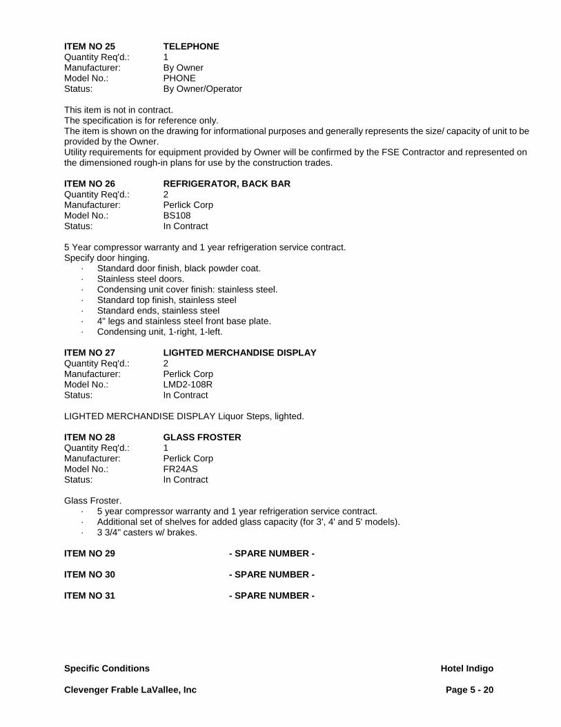
Specific Conditions Hotel Indigo
Clevenger Frable LaVallee, Inc Page 5 - 20
ITEM NO 25 TELEPHONE Quantity Req'd.: 1 Manufacturer: By Owner Model No.: PHONE Status: By Owner/Operator This item is not in contract. The specification is for reference only. The item is shown on the drawing for informational purposes and generally represents the size/ capacity of unit to be provided by the Owner. Utility requirements for equipment provided by Owner will be confirmed by the FSE Contractor and represented on the dimensioned rough-in plans for use by the construction trades. ITEM NO 26 REFRIGERATOR, BACK BAR Quantity Req'd.: 2 Manufacturer: Perlick Corp Model No.: BS108 Status: In Contract 5 Year compressor warranty and 1 year refrigeration service contract. Specify door hinging.
· Standard door finish, black powder coat. · Stainless steel doors. · Condensing unit cover finish: stainless steel. · Standard top finish, stainless steel · Standard ends, stainless steel · 4" legs and stainless steel front base plate. · Condensing unit, 1-right, 1-left.
ITEM NO 27 LIGHTED MERCHANDISE DISPLAY Quantity Req'd.: 2 Manufacturer: Perlick Corp Model No.: LMD2-108R Status: In Contract LIGHTED MERCHANDISE DISPLAY Liquor Steps, lighted. ITEM NO 28 GLASS FROSTER Quantity Req'd.: 1 Manufacturer: Perlick Corp Model No.: FR24AS Status: In Contract Glass Froster.
· 5 year compressor warranty and 1 year refrigeration service contract. · Additional set of shelves for added glass capacity (for 3', 4' and 5' models). · 3 3/4" casters w/ brakes.
ITEM NO 29 - SPARE NUMBER - ITEM NO 30 - SPARE NUMBER - ITEM NO 31 - SPARE NUMBER -

Specific Conditions Hotel Indigo
Clevenger Frable LaVallee, Inc Page 5 - 21
ITEM NO 32 BOTTLE RAIL, LOCKING Quantity Req'd.: 1 Manufacturer: Perlick Corp Model No.: SR-SL24 Status: In Contract Speed Rail Bottle Holder ITEM NO 33 ICE CHEST W/COLD PLATE Quantity Req'd.: 1 Manufacturer: Perlick Corp Model No.: TS36IC10 Status: In Contract Ice Chest W/Cold Plate.
· Right end splash. · Back splash cutout for soda lines · 6 wells/ 7 condiment cups for 36" ice chests
ITEM NO 34 BOTTLE RAIL, LOCKING Quantity Req'd.: 2 Manufacturer: Perlick Corp Model No.: SR-SL36 Status: In Contract Speed Rail Bottle Holder ITEM NO 35 BAR GUN, 8 BUTTON Quantity Req'd.: 1 Manufacturer: Cornelius Model No.: BAR MASTER Status: By Product Supplier/Vendor This item is not in contract. The specification is for reference only. The item is shown on the drawing for informational purposes and generally represents the size/ capacity of unit to be provided by Product Supplier/ Vendor. Any utility connections indicated on drawings are representative and intended to assist the Engineer in planning base building utility systems. Actual utility requirements will be confirmed by the Foodservice Equipment Contractor and represented on the dimensioned rough-in plans for use by the construction trades. The Foodservice Equipment Contractor will provide flexible utility disconnects for this item per the specific conditions section of the contract. ITEM NO 36 BLENDER STATION Quantity Req'd.: 2 Manufacturer: Perlick Corp Model No.: TS12BLW Status: In Contract Blender Station w/ Sink Perforated rinse tank dump boxes for blender stations

Specific Conditions Hotel Indigo
Clevenger Frable LaVallee, Inc Page 5 - 22
ITEM NO 37 BLENDER W/ HOOD Quantity Req'd.: 2 Manufacturer: Hamilton Beach Model No.: HBB-908 Status: In Contract Blender W/ hood.
· Express Care Service Program · Polycarbonate container.
ITEM NO 38 TRASH RECEPTACLE (SLIM JIM) Quantity Req'd.: 2 Manufacturer: Rubbermaid Model No.: 3540 Status: By Owner This item is not in contract. The specification is for reference only. The item is shown on the drawing for informational purposes and generally represents the size/ capacity of unit to be provided by the Owner. ITEM NO 39 - SPARE NUMBER - ITEM NO 40 - SPARE NUMBER - ITEM NO 41 - SPARE NUMBER - ITEM NO 42 STORAGE CABINET W/ DRAINBOARD TOP Quantity Req'd.: 1 Manufacturer: Perlick Corp Model No.: SC24 Status: In Contract Storage Cabinet W/ drainboard Top.
· Door ITEM NO 43 POS TERMINAL Quantity Req'd.: 2 Manufacturer: By Owner Model No.: POS-T Status: By Owner/Operator Cash Register / POS System, electronic type, with CRT display, without cash drawer, plastic finish. This item is not in contract. The specification is for reference only. The item is shown on the drawing for informational purposes and generally represents the size/ capacity of unit to be provided by the Owner. ITEM NO 44 POS PRINTER Quantity Req'd.: 3 Manufacturer: By Owner Model No.: POS-P Status: By Owner/Operator Spec Data Not Found for This Item This item is not in contract. The specification is for reference only. The item is shown on the drawing for informational purposes and generally represents the size/ capacity of unit to be provided by the Owner.

Specific Conditions Hotel Indigo
Clevenger Frable LaVallee, Inc Page 5 - 23
ITEM NO 45 DISPENSER, BEER Quantity Req'd.: 1 Manufacturer: Beverage Air Model No.: DD50-1-S-01 Status: In Contract Draft Beer Dispenser, column type, polished chrome column finish, with chrome-plated faucets. Faucet locks, door locks. ITEM NO 46 GLASS FROSTER Quantity Req'd.: 1 Manufacturer: Perlick Corp Model No.: FR24AS Status: In Contract Glass Froster
· 5 year compressor warranty and 1 year refrigeration service contract. · Additional set of shelves for added glass capacity (for 3', 4' and 5' models). · 3 3/4" casters w/ brakes.
ITEM NO 47 BOTTLE RAIL, LOCKING Quantity Req'd.: 1 Manufacturer: Perlick Corp Model No.: SR-SL24 Status: In Contract Speed Rail Bottle Holder ITEM NO 48 ICE CHEST W/COLD PLATE Quantity Req'd.: 1 Manufacturer: Perlick Corp Model No.: TS36IC10 Status: In Contract Ice Chest W/Cold Plate.
· Right end splash. · Back splash cutout for soda lines · 6 wells/ 7 condiment cups for 36", ice chests
ITEM NO 49 - SPARE NUMBER - ITEM NO 50 - SPARE NUMBER - ITEM NO 51 - SPARE NUMBER - ITEM NO 52 BOTTLE RAIL, LOCKING Quantity Req'd.: 2 Manufacturer: Perlick Corp Model No.: SR-SL36 Status: In Contract Speed Rail Bottle Holder

Specific Conditions Hotel Indigo
Clevenger Frable LaVallee, Inc Page 5 - 24
ITEM NO 53 BAR GUN, 8 BUTTON Quantity Req'd.: 1 Manufacturer: Cornelius Model No.: BAR MASTER Status: By Product Supplier/Vendor This item is not in contract. The specification is for reference only. The item is shown on the drawing for informational purposes and generally represents the size/ capacity of unit to be provided by Product Supplier/ Vendor. Any utility connections indicated on drawings are representative and intended to assist the Engineer in planning base building utility systems. Actual utility requirements will be confirmed by the Foodservice Equipment Contractor and represented on the dimensioned rough-in plans for use by the construction trades. The Foodservice Equipment Contractor will provide flexible utility disconnects for this item per the specific conditions section of the contract. ITEM NO 54 STORAGE CABINET W/ DRAINBOARD TOP Quantity Req'd.: 1 Manufacturer: Perlick Corp Model No.: SC18 Status: In Contract Storage Cabinet W/ drainboard Top. ITEM NO 55 GLASSWASHER Quantity Req'd.: 1 Manufacturer: Perlick Corp Model No.: PKD24A Status: In Contract Glass Washer, low temperature chemical sanitizing, manual loading, single glass rack design, single door opening, all stainless steel finish. 3 racks. ITEM NO 56 HAND SINK W/TOWEL DISPENSER Quantity Req'd.: 1 Manufacturer: Perlick Corp Model No.: TS12HSN Status: In Contract Hand Sink Unit, free standing design, with faucet, soap dispenser and towel dispenser, stainless steel construction including legs. ITEM NO 57 STORAGE CABINET W/ DRAINBOARD TOP Quantity Req'd.: 1 Manufacturer: Perlick Corp Model No.: SC24 Status: In Contract Storage Cabinet W/ drainboard Top.
· Door
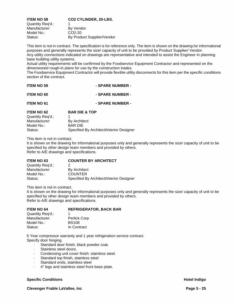
Specific Conditions Hotel Indigo
Clevenger Frable LaVallee, Inc Page 5 - 25
ITEM NO 58 CO2 CYLINDER, 20-LBS. Quantity Req'd.: 1 Manufacturer: By Vendor Model No.: CO2-20 Status: By Product Supplier/Vendor This item is not in contract. The specification is for reference only. The item is shown on the drawing for informational purposes and generally represents the size/ capacity of unit to be provided by Product Supplier/ Vendor. Any utility connections indicated on drawings are representative and intended to assist the Engineer in planning base building utility systems. Actual utility requirements will be confirmed by the Foodservice Equipment Contractor and represented on the dimensioned rough-in plans for use by the construction trades. The Foodservice Equipment Contractor will provide flexible utility disconnects for this item per the specific conditions section of the contract. ITEM NO 59 - SPARE NUMBER - ITEM NO 60 - SPARE NUMBER - ITEM NO 61 - SPARE NUMBER - ITEM NO 62 BAR DIE & TOP Quantity Req'd.: 1 Manufacturer: By Architect Model No.: BAR DIE Status: Specified By Architect/Interior Designer This item is not in contract. It is shown on the drawing for informational purposes only and generally represents the size/ capacity of unit to be specified by other design team members and provided by others. Refer to A/E drawings and specifications. ITEM NO 63 COUNTER BY ARCHITECT Quantity Req'd.: 2 Manufacturer: By Architect Model No.: COUNTER Status: Specified By Architect/Interior Designer This item is not in contract. It is shown on the drawing for informational purposes only and generally represents the size/ capacity of unit to be specified by other design team members and provided by others. Refer to A/E drawings and specifications. ITEM NO 64 REFRIGERATOR, BACK BAR Quantity Req'd.: 1 Manufacturer: Perlick Corp Model No.: BS108 Status: In Contract 5 Year compressor warranty and 1 year refrigeration service contract. Specify door hinging.
· Standard door finish, black powder coat. · Stainless steel doors. · Condensing unit cover finish: stainless steel. · Standard top finish, stainless steel · Standard ends, stainless steel · 4" legs and stainless steel front base plate.

Specific Conditions Hotel Indigo
Clevenger Frable LaVallee, Inc Page 5 - 26
ITEM NO 65 MILLWORK CABINET Quantity Req'd.: 1 Manufacturer: Custom Fabricated Assembly Model No.: Custom-Fabrication Status: Specified By Architect/Interior Designer Cabinet, Storage, enclosed cabinet base with hinged doors, width and height as shown on drawings, 36" overall length. This item is not in contract. It is shown on the drawing for informational purposes only and generally represents the size/ capacity of unit to be specified by other design team members and provided by others. Refer to A/E drawings and specifications. ITEM NO 66 LIGHTED MERCHANDISE DISPLAY Quantity Req'd.: 2 Manufacturer: Perlick Corp Model No.: LMD2-108R Status: In Contract LIGHTED MERCHANDISE DISPLAY Liquor Steps, lighted. ITEM NO 67 ICE CHEST, DROP IN Quantity Req'd.: 1 Manufacturer: Perlick Corp Model No.: DI24IC Status: In Contract Ice Chest, Drop In.
· Sliding S/S Top · Free-standing ice divider
ITEM NO 68 WATER PURIFICATION SYSTEM Quantity Req'd.: 1 Manufacturer: Natura Water Model No.: B-MODEL Status: In Contract Water Filter, Ice Machines, double cartridge Provide water treatment unit per specific conditions. ITEM NO 69 - SPARE NUMBER - ITEM NO 70 - SPARE NUMBER - ITEM NO 71 - SPARE NUMBER - ITEM NO 72 POS TERMINAL Quantity Req'd.: 2 Manufacturer: By Owner Model No.: POS-T Status: By Owner/Operator Cash Register / POS System, electronic type, with CRT display, without cash drawer, plastic finish. This item is not in contract. The specification is for reference only. The item is shown on the drawing for informational purposes and generally represents the size/ capacity of unit to be provided by the Owner.

Specific Conditions Hotel Indigo
Clevenger Frable LaVallee, Inc Page 5 - 27
ITEM NO 73 POS PRINTER Quantity Req'd.: 2 Manufacturer: By Owner Model No.: POS-P Status: By Owner/Operator Spec Data Not Found for This Item This item is not in contract. The specification is for reference only. The item is shown on the drawing for informational purposes and generally represents the size/ capacity of unit to be provided by the Owner. ITEM NO 74 UNDERBAR GLASS FROSTER Quantity Req'd.: 1 Manufacturer: Glastender Inc Model No.: MFV48 Status: In Contract Glass Froster, underbar model, w/self-contained refrig system, front opening, two doors, approximately 48" long, all stainless steel exterior. ITEM NO 75 HAND SINK, DROP-IN Quantity Req'd.: 1 Manufacturer: Advance Inc. Model No.: DI-1-10 Status: In Contract Hand Sink, drop-in type, 10" x 14" sink compartment, all stainless steel construction, with swing spout faucet.
· Heavy duty gooseneck faucet w/wrist handles. · End splash, left add suffix "L" to model number.
ITEM NO 76 ICE CHEST W/COLD PLATE Quantity Req'd.: 2 Manufacturer: Perlick Corp Model No.: TS24IC10 Status: In Contract Ice Chest W/Cold Plate.
· 2- Right end splash. · 1- Left end splash. · Back splash cutout for soda lines · 6 wells/ 4 condiment cups for 24" ice chest.
ITEM NO 77 BOTTLE RAIL, LOCKING Quantity Req'd.: 4 Manufacturer: Perlick Corp Model No.: SR-SL24 Status: In Contract Speed Rail Bottle Holder

Specific Conditions Hotel Indigo
Clevenger Frable LaVallee, Inc Page 5 - 28
ITEM NO 78 HAND SINK W/TOWEL DISPENSER Quantity Req'd.: 1 Manufacturer: Perlick Corp Model No.: TS12HSN Status: In Contract Hand Sink Unit, free standing design, with faucet, soap dispenser and towel dispenser, stainless steel construction including legs. ITEM NO 79 TOWEL DISPENSER (BY OWNER) Quantity Req'd.: 1 Manufacturer: By Owner Model No.: TOWEL DISPENSER Status: By Owner/Operator Dispenser, Napkin, This item is not in contract. The specification is for reference only. The item is shown on the drawing for informational purposes and generally represents the size/ capacity of unit to be provided by the Owner. ITEM NO 80 POS SYSTEM Quantity Req'd.: 1 Manufacturer: By Owner Model No.: POS-1 Status: By Owner/Operator Cash Register / POS System, Point-Of-Sale computerized type This item is not in contract. The specification is for reference only. The item is shown on the drawing for informational purposes and generally represents the size/ capacity of unit to be provided by the Owner. ITEM NO 81 POS PRINTER Quantity Req'd.: 1 Manufacturer: By Owner Model No.: POS-P Status: By Owner/Operator This item is not in contract. The specification is for reference only. The item is shown on the drawing for informational purposes and generally represents the size/ capacity of unit to be provided by the Owner. ITEM NO 82 TRASH RECEPTACLE (SLIM JIM) Quantity Req'd.: 3 Manufacturer: Rubbermaid Model No.: 3540 Status: By Owner This item is not in contract. The specification is for reference only. The item is shown on the drawing for informational purposes and generally represents the size/ capacity of unit to be provided by the Owner.
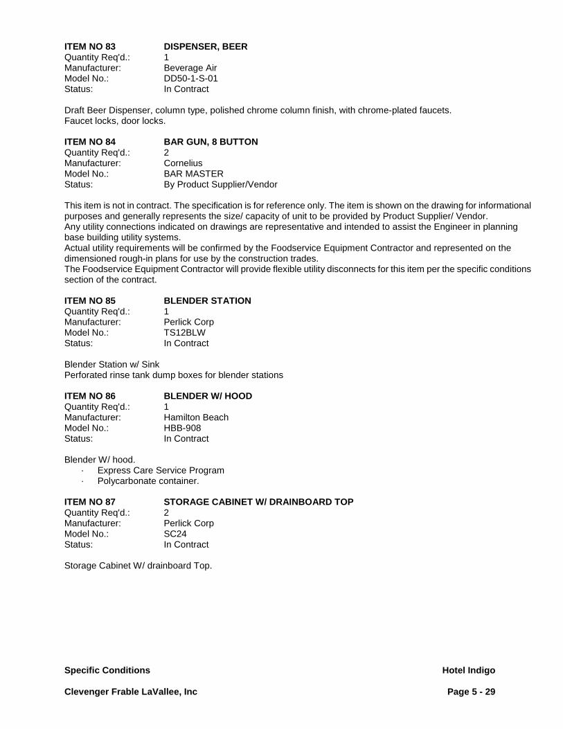
Specific Conditions Hotel Indigo
Clevenger Frable LaVallee, Inc Page 5 - 29
ITEM NO 83 DISPENSER, BEER Quantity Req'd.: 1 Manufacturer: Beverage Air Model No.: DD50-1-S-01 Status: In Contract Draft Beer Dispenser, column type, polished chrome column finish, with chrome-plated faucets. Faucet locks, door locks. ITEM NO 84 BAR GUN, 8 BUTTON Quantity Req'd.: 2 Manufacturer: Cornelius Model No.: BAR MASTER Status: By Product Supplier/Vendor This item is not in contract. The specification is for reference only. The item is shown on the drawing for informational purposes and generally represents the size/ capacity of unit to be provided by Product Supplier/ Vendor. Any utility connections indicated on drawings are representative and intended to assist the Engineer in planning base building utility systems. Actual utility requirements will be confirmed by the Foodservice Equipment Contractor and represented on the dimensioned rough-in plans for use by the construction trades. The Foodservice Equipment Contractor will provide flexible utility disconnects for this item per the specific conditions section of the contract. ITEM NO 85 BLENDER STATION Quantity Req'd.: 1 Manufacturer: Perlick Corp Model No.: TS12BLW Status: In Contract Blender Station w/ Sink Perforated rinse tank dump boxes for blender stations ITEM NO 86 BLENDER W/ HOOD Quantity Req'd.: 1 Manufacturer: Hamilton Beach Model No.: HBB-908 Status: In Contract Blender W/ hood.
· Express Care Service Program · Polycarbonate container.
ITEM NO 87 STORAGE CABINET W/ DRAINBOARD TOP Quantity Req'd.: 2 Manufacturer: Perlick Corp Model No.: SC24 Status: In Contract Storage Cabinet W/ drainboard Top.

Specific Conditions Hotel Indigo
Clevenger Frable LaVallee, Inc Page 5 - 30
ITEM NO 88 GLASSWASHER Quantity Req'd.: 1 Manufacturer: Perlick Corp Model No.: PKD24A Status: In Contract Glass Washer, low temperature chemical sanitizing, manual loading, single glass rack design, single door opening, all stainless steel finish, 3 racks. Location: Sub-Cellar Bulk Storage
ITEM NO 200 WALK-IN COOLER/ FREEZER, MULTI-COMPARTMENT Quantity Req'd.: 1 Manufacturer: Nor-Lake, Inc Model No.: Custom Status: In Contract Unit to be a Refrigerator +35° F. and/or Freezer -10° F. of size and shape as shown on plan x 6' -7 " high. Wall and ceiling panels shall be 4" urethane, U.L.Flame Spread 25 insulation. Panels are without wooden structural members. Thru ceiling door electrical assembly as shown on detail E-1-4. One (1) lot of trim strip, where required to close in wall gaps, of same finish as exterior panels to finished ceiling. (F.S.E. Contractor to verify height). Unexposed exterior finish to be galvalume. Unit must comply with the Jan. 1, 2009 Federal Energy Regulations. Options:
· 4” structural insulated Floor with interior ramps on exterior doors · .040 embossed aluminum white interior and exposed exterior. · Hinged entrance door(s) w/ Kason K-1094 automatic door closer, three (3) Kason polished chrome hinges
with spring assists, and Kason #27C polished chrome handle, hinged as shown on plan. Hinged doors to be 34” or 36" as shown wide x 66" high.
· Approved Kason #1810 48" LED 2-bulb, low-temp light fixtures for ceiling and Kason #1806 LED light fixture at each door installed and wired by the Electrical Division per detail E-1-4.(See electrical plan for quantity and location of lights and switches)
· Modularm 75B, recessed with thru ceiling door electrical as shown on detail E-1-4. · 2-1/2” dial thermometer flush-mounted. · 4” x 4” x height of walk-in x 1/8” diamond plate corner guards at exposed corners. · 1/8" aluminum diamond tread kick plate, 3'- 0" high on door exterior and up to the bottom frame of the view
window on the door interior. Exterior and interior of door jambs to be 3' high. Do not use pop rivet fasteners. Use counter-sunk stainless steel phillips-head screws to secure treadplate.
· Skid strips on aluminum floor of freezer. CLEVENGER FRABLE LAVALLEE INC. FIT & FINISH REQUIREMENT: Fit & Finish: The top closure, side trim strips, 1/8" aluminum diamond plate wainscot, and the vinyl rub rail are all to be back-ordered by the Foodservice Equipment Contractor. Once the walk-in is constructed and the finish floor work completed, the Foodservice Equipment Contractor is required to measure accurately for these accessories per the CFL details shown on the submittal drawings. Tread plate panels are to be secured to walk-in with countersunk, stainless steel, phillips head screws. Also, the audio-visual alarm probe wire and the dial thermometer probe wire must be uncoiled, extended and fastened neatly to the walls with the attachment clips that are provided by the manufacturer. Per Clevenger Frable LaVallee, Inc. specification requirement, the GC is to insure and the FSEC is to confirm that the floor slab in the walk-in footprint area meets an FF50 flatness and an FL40 levelness standard as defined by the American Concrete Institute prior to the walk-in being erected. This requirement is necessary to insure proper fit of modular insulated panels and achieve level/plumb end result.

Specific Conditions Hotel Indigo
Clevenger Frable LaVallee, Inc Page 5 - 31
ITEM NO 201 EVAPORATOR COIL, MEDIUM TEMPERATURE Quantity Req'd.: 1 Manufacturer: Nor-Lake, Inc Model No.: SA28-106B-AE Status: In Contract
· Connect to Item 201a, Refrigeration Condenser. Unit to be adequately sized to operate Item 200, Refrigerator Compartment @ +35° F. Electrical hook-up and interconnecting of system to be by the Electrical Contractor. Indirect waste line extended to floor sink (drain) by FSE Contractor. Refer to Specific Conditions 2.10 Cold Storage Rooms, P. Drain Lines. ITEM NO 201-a CONDENSING UNIT, WATER COOLED Quantity Req'd.: 1 Manufacturer: Nor-Lake, Inc Model No.: NWWD125RL/3 Status: In Contract F.S.E.C. to provide the necessary refrigeration lines required to operate and maintain the refrigeration system for Item 200, refrigerated compartment. Unit to be part of the remote refrigeration system for Item 201, Evaporator Coil. F.S.E.C. to coordinate with the electrical/ plumbing contractor to provide a complete and operable refrigeration system. Provide start-up, five (5) year compressor warranty and one (1) year refrigeration service contract. Division 26 to wire to safety disconnect switch.
· See Architectural plan for location. · Provide refrigeration lines of length and diameter to suit this application. · Provide water regulating valve suitable for 45 - 55 degree condensing water temperature. · Protective cover for "inside" application. · Provide with vibration isolators.
ITEM NO 202 - SPARE NUMBER - ITEM NO 203 - SPARE NUMBER - ITEM NO 204 - SPARE NUMBER - ITEM NO 205 EVAPORATOR COIL, LOW TEMPERATURE Quantity Req'd.: 1 Manufacturer: Nor-Lake, Inc Model No.: SE26-60B-DE Status: In Contract
· Connect to Item 205a, Refrigeration Condenser. Unit to be adequately sized to operate Item 200, Freezer Compartment @ -10° F. Electrical hook-up and interconnecting of system to be by the Electrical Contractor. Heat tape for low temp coil drain line furnished and set-in-place by the FSE Contractor. Final electrical connection to heat tape by Electrical Division. Indirect waste line extended to floor sink (drain) by FSE Contractor. Refer to Specific Conditions 2.10 Cold Storage Rooms, P. Drain Lines.
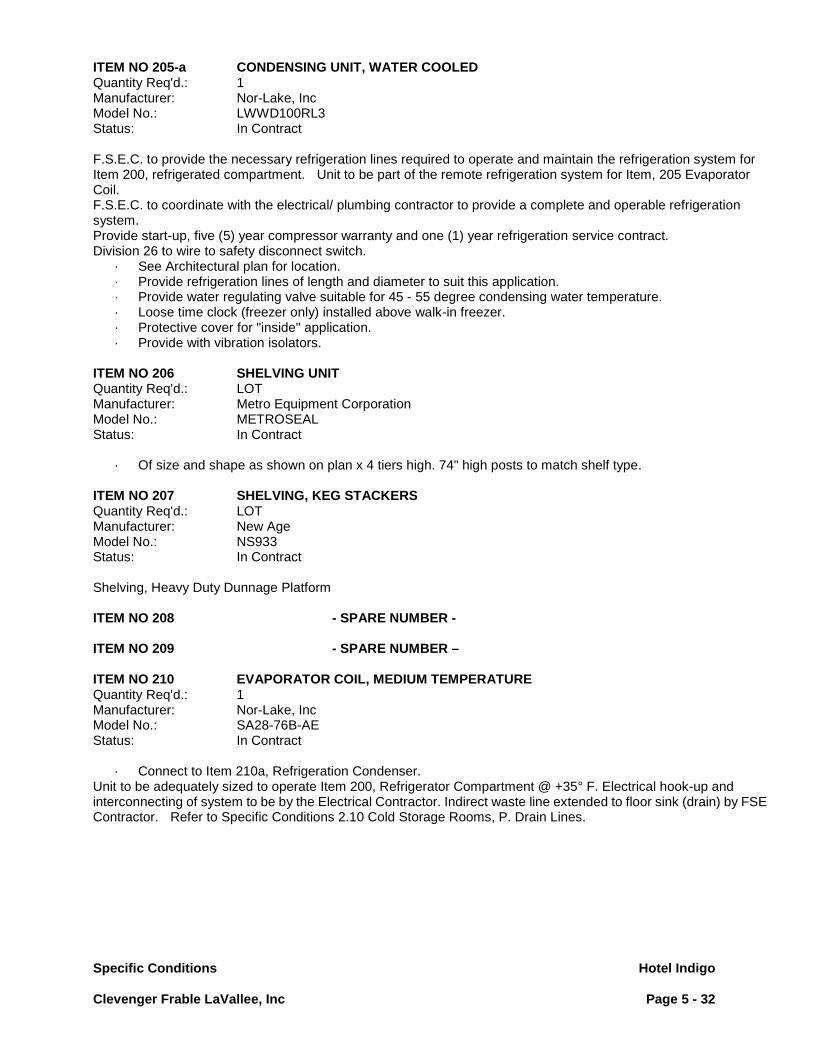
Specific Conditions Hotel Indigo
Clevenger Frable LaVallee, Inc Page 5 - 32
ITEM NO 205-a CONDENSING UNIT, WATER COOLED Quantity Req'd.: 1 Manufacturer: Nor-Lake, Inc Model No.: LWWD100RL3 Status: In Contract F.S.E.C. to provide the necessary refrigeration lines required to operate and maintain the refrigeration system for Item 200, refrigerated compartment. Unit to be part of the remote refrigeration system for Item, 205 Evaporator Coil. F.S.E.C. to coordinate with the electrical/ plumbing contractor to provide a complete and operable refrigeration system. Provide start-up, five (5) year compressor warranty and one (1) year refrigeration service contract. Division 26 to wire to safety disconnect switch.
· See Architectural plan for location. · Provide refrigeration lines of length and diameter to suit this application. · Provide water regulating valve suitable for 45 - 55 degree condensing water temperature. · Loose time clock (freezer only) installed above walk-in freezer. · Protective cover for "inside" application. · Provide with vibration isolators.
ITEM NO 206 SHELVING UNIT Quantity Req'd.: LOT Manufacturer: Metro Equipment Corporation Model No.: METROSEAL Status: In Contract
· Of size and shape as shown on plan x 4 tiers high. 74" high posts to match shelf type. ITEM NO 207 SHELVING, KEG STACKERS Quantity Req'd.: LOT Manufacturer: New Age Model No.: NS933 Status: In Contract Shelving, Heavy Duty Dunnage Platform ITEM NO 208 - SPARE NUMBER - ITEM NO 209 - SPARE NUMBER – ITEM NO 210 EVAPORATOR COIL, MEDIUM TEMPERATURE Quantity Req'd.: 1 Manufacturer: Nor-Lake, Inc Model No.: SA28-76B-AE Status: In Contract
· Connect to Item 210a, Refrigeration Condenser. Unit to be adequately sized to operate Item 200, Refrigerator Compartment @ +35° F. Electrical hook-up and interconnecting of system to be by the Electrical Contractor. Indirect waste line extended to floor sink (drain) by FSE Contractor. Refer to Specific Conditions 2.10 Cold Storage Rooms, P. Drain Lines.

Specific Conditions Hotel Indigo
Clevenger Frable LaVallee, Inc Page 5 - 33
ITEM NO 210-a CONDENSING UNIT, WATER COOLED Quantity Req'd.: 1 Manufacturer: Nor-Lake, Inc Model No.: NWWD125RL/3 Status: In Contract F.S.E.C. to provide the necessary refrigeration lines required to operate and maintain the refrigeration system for Item 200, refrigerated compartment. Unit to be part of the remote refrigeration system for Item 210, Evaporator Coil. F.S.E.C. to coordinate with the electrical/ plumbing contractor to provide a complete and operable refrigeration system. Provide start-up, five (5) year compressor warranty and one (1) year refrigeration service contract. Division 26 to wire to safety disconnect switch.
· See Architectural plan for location. · Provide refrigeration lines of length and diameter to suit this application. · Provide water regulating valve suitable for 45 - 55 degree condensing water temperature. · Norlake condensing unit rack, angle iron construction, welded and painted. · Protective cover for "inside" application. · Provide with vibration isolators.
ITEM NO 211 EVAPORATOR COIL, MEDIUM TEMPERATURE Quantity Req'd.: 1 Manufacturer: Nor-Lake, Inc Model No.: SA28-76B-AE Status: In Contract
· Connect to Item 210a, Refrigeration Condenser. Unit to be adequately sized to operate Item 200, Refrigerator Compartment @ +35° F. Electrical hook-up and interconnecting of system to be by the Electrical Contractor. Indirect waste line extended to floor sink (drain) by FSE Contractor. Refer to Specific Conditions 2.10 Cold Storage Rooms, P. Drain Lines. ITEM NO 212 REFRIGERATOR PAN RACKS Quantity Req'd.: 4 Manufacturer: New Age Model No.: 1335 Status: In Contract Pan Racks, Heavy Duty welded tubular aluminum.
· Pan Stops. ITEM NO 213 SHELVING UNIT Quantity Req'd.: LOT Manufacturer: Metro Equipment Corporation Model No.: Super Erecta Chrome Status: In Contract Of size and shape as shown on plan x 5 tiers high. 84" high posts to match shelf type.
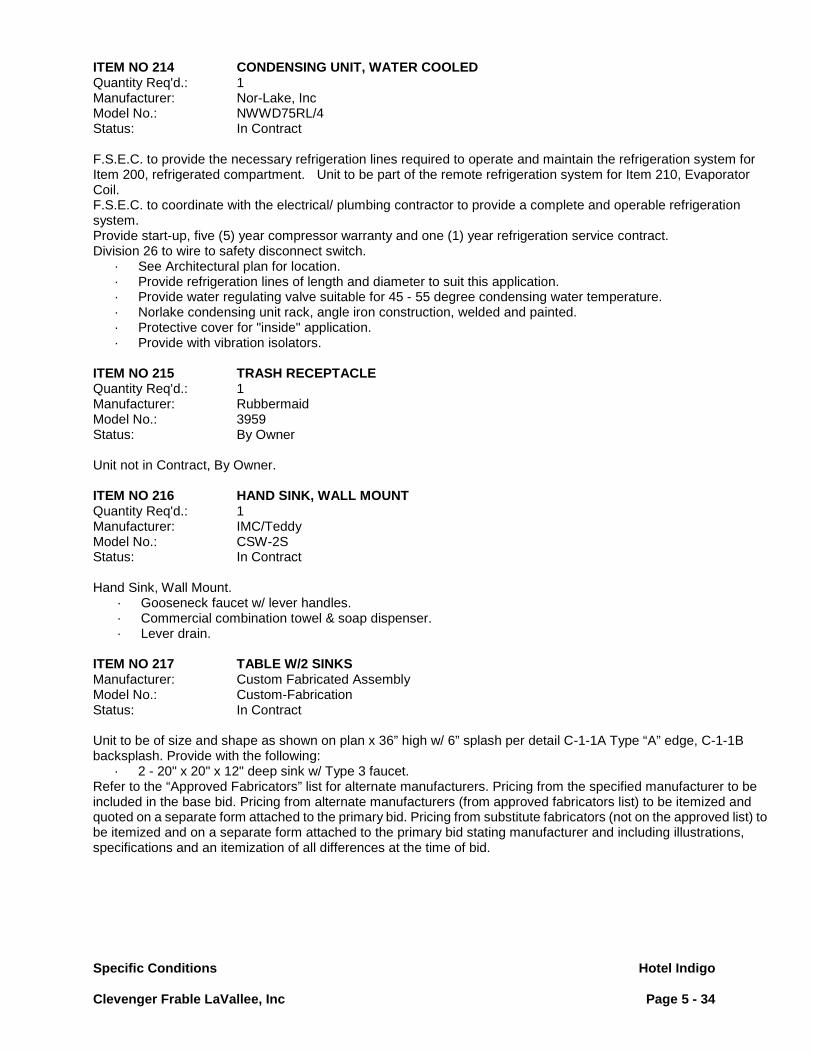
Specific Conditions Hotel Indigo
Clevenger Frable LaVallee, Inc Page 5 - 34
ITEM NO 214 CONDENSING UNIT, WATER COOLED Quantity Req'd.: 1 Manufacturer: Nor-Lake, Inc Model No.: NWWD75RL/4 Status: In Contract F.S.E.C. to provide the necessary refrigeration lines required to operate and maintain the refrigeration system for Item 200, refrigerated compartment. Unit to be part of the remote refrigeration system for Item 210, Evaporator Coil. F.S.E.C. to coordinate with the electrical/ plumbing contractor to provide a complete and operable refrigeration system. Provide start-up, five (5) year compressor warranty and one (1) year refrigeration service contract. Division 26 to wire to safety disconnect switch.
· See Architectural plan for location. · Provide refrigeration lines of length and diameter to suit this application. · Provide water regulating valve suitable for 45 - 55 degree condensing water temperature. · Norlake condensing unit rack, angle iron construction, welded and painted. · Protective cover for "inside" application. · Provide with vibration isolators.
ITEM NO 215 TRASH RECEPTACLE Quantity Req'd.: 1 Manufacturer: Rubbermaid Model No.: 3959 Status: By Owner Unit not in Contract, By Owner. ITEM NO 216 HAND SINK, WALL MOUNT Quantity Req'd.: 1 Manufacturer: IMC/Teddy Model No.: CSW-2S Status: In Contract Hand Sink, Wall Mount.
· Gooseneck faucet w/ lever handles. · Commercial combination towel & soap dispenser. · Lever drain.
ITEM NO 217 TABLE W/2 SINKS Manufacturer: Custom Fabricated Assembly Model No.: Custom-Fabrication Status: In Contract Unit to be of size and shape as shown on plan x 36” high w/ 6” splash per detail C-1-1A Type “A” edge, C-1-1B backsplash. Provide with the following:
· 2 - 20" x 20" x 12" deep sink w/ Type 3 faucet. Refer to the “Approved Fabricators” list for alternate manufacturers. Pricing from the specified manufacturer to be included in the base bid. Pricing from alternate manufacturers (from approved fabricators list) to be itemized and quoted on a separate form attached to the primary bid. Pricing from substitute fabricators (not on the approved list) to be itemized and on a separate form attached to the primary bid stating manufacturer and including illustrations, specifications and an itemization of all differences at the time of bid.

Specific Conditions Hotel Indigo
Clevenger Frable LaVallee, Inc Page 5 - 35
ITEM NO 218 WALL SHELF Manufacturer: Custom Fabricated Assembly Model No.: Custom-Fabrication Status: In Contract Unit to be of size and shape as shown on plan per detail C-1-2 with the following requirements:
· Louvers per detail C-1-2. ITEM NO 219 - SPARE NUMBER - ITEM NO 220 - SPARE NUMBER - ITEM NO 221 - SPARE NUMBER – ITEM NO 222 RED WINE REFRIGERATOR Quantity Req'd.: 2 Manufacturer: INFINITY Model No.: 332 Status: In Contract Wine refrigerated cabinets, two section All Std equipment.
· 332 bottles on 32 shelves, dual zone cooling. ITEM NO 223 SECURITY UNIT, MOBILE Quantity Req'd.: 1 LOT Manufacturer: Metro Equip Model No.: SEC55LC Status: In Contract Shelving, Mobile, Of size and shape as shown on plan.
· 2 intermediate shelves. ITEM NO 224 MOP SINK STORAGE CABINET Quantity Req'd.: 1 Manufacturer: Eagle Model No.: F1916-VSCS Status: In Contract Mop Sink, floor mounted
· Mop holder, 2 pole · Service faucet. · 36" long hose w/ faucet connection at one end.
ITEM NO 225 SECURITY UNIT, MOBILE Quantity Req'd.: 1 Manufacturer: Metro Equip Model No.: SEC55LC Status: In Contract Shelving, Mobile, Of size and shape as shown on plan.
· 2 intermediate shelves

Fabrication Details Clevenger Frable LaVallee
Hotel Indigo Page 6 - 1
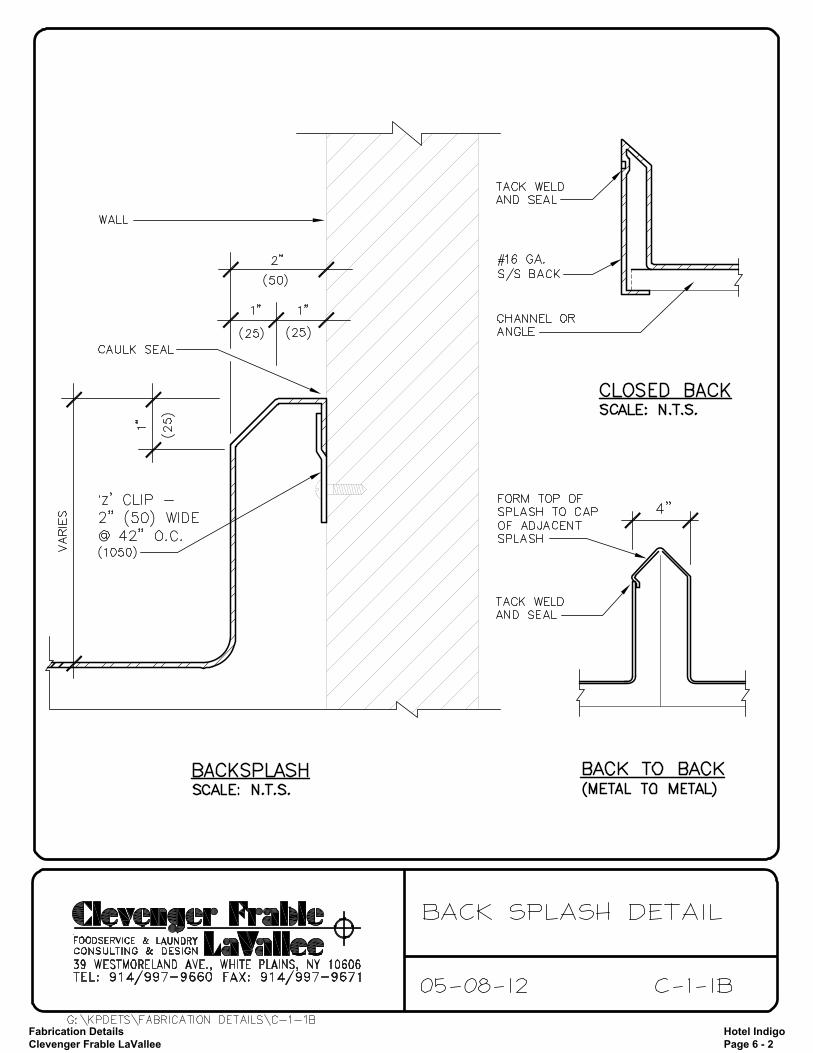
Fabrication Details Clevenger Frable LaVallee
Hotel Indigo Page 6 - 2

Fabrication Details Clevenger Frable LaVallee
Hotel Indigo Page 6 - 3
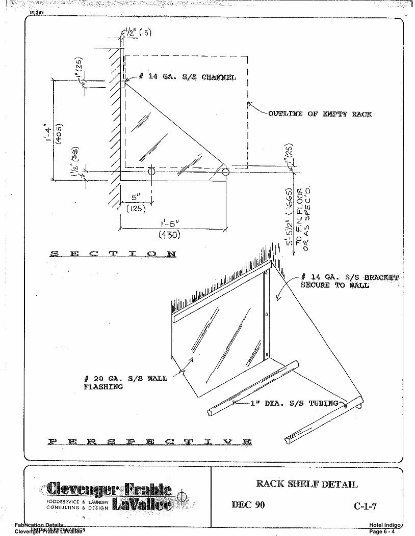
Fabrication Details Clevenger Frable LaVallee
Hotel Indigo Page 6 - 4

Fabrication Details Clevenger Frable LaVallee
Hotel Indigo Page 6 - 5
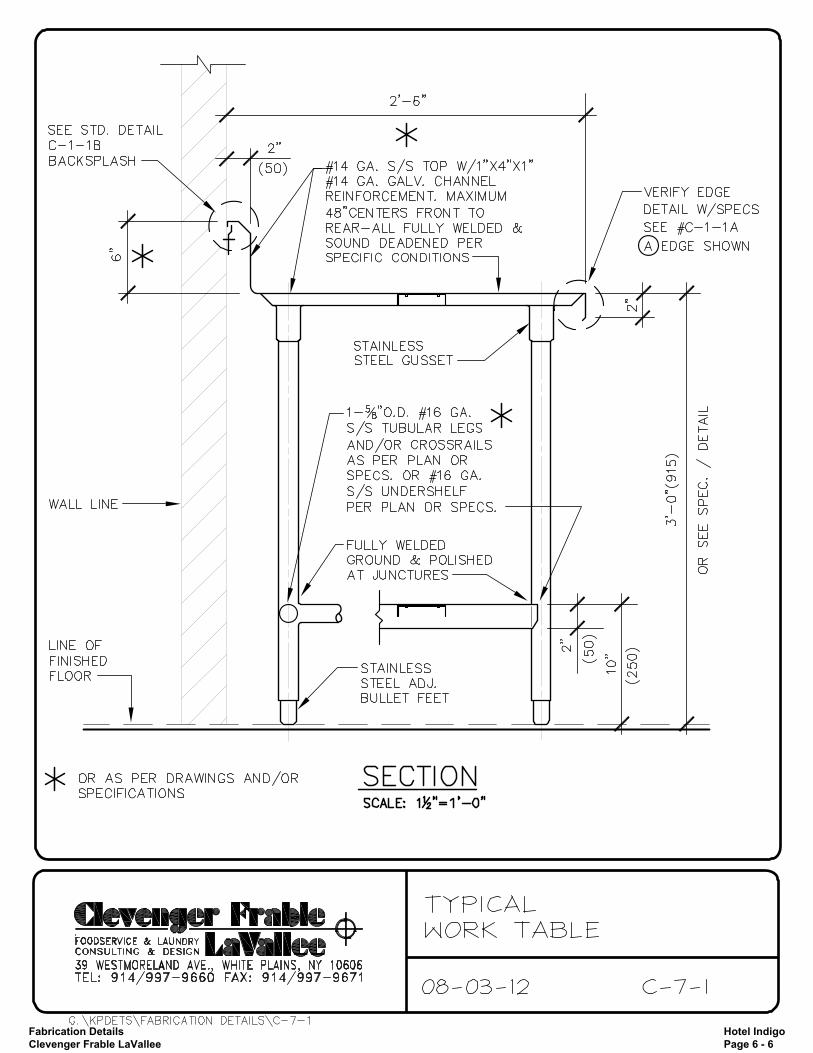
Fabrication Details Clevenger Frable LaVallee
Hotel Indigo Page 6 - 6
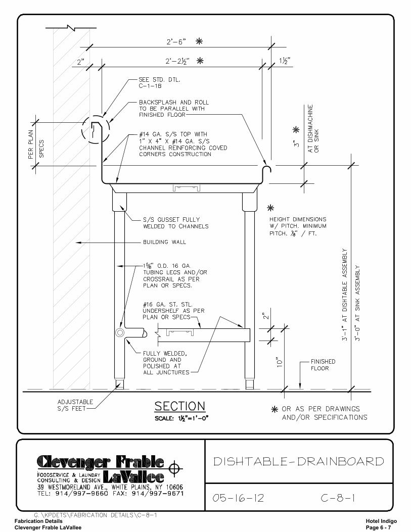
Fabrication Details Clevenger Frable LaVallee
Hotel Indigo Page 6 - 7

Fabrication Details Clevenger Frable LaVallee
Hotel Indigo Page 6 - 8

Fabrication Details Clevenger Frable LaVallee
Hotel Indigo Page 6 - 9

Fabrication Details Clevenger Frable LaVallee
Hotel Indigo Page 6 - 10

Fabrication Details Clevenger Frable LaVallee
Hotel Indigo Page 6 - 11

Fabrication Details Clevenger Frable LaVallee
Hotel Indigo Page 6 - 12
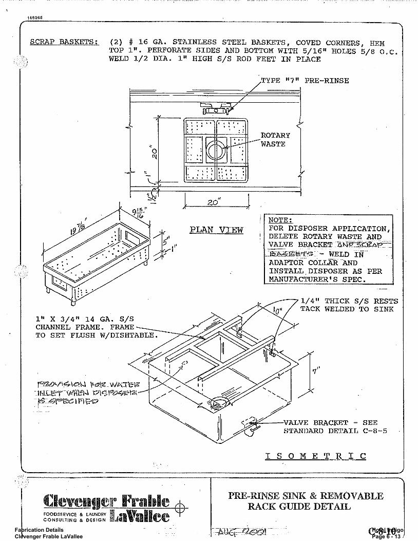
Fabrication Details Clevenger Frable LaVallee
Hotel Indigo Page 6 - 13
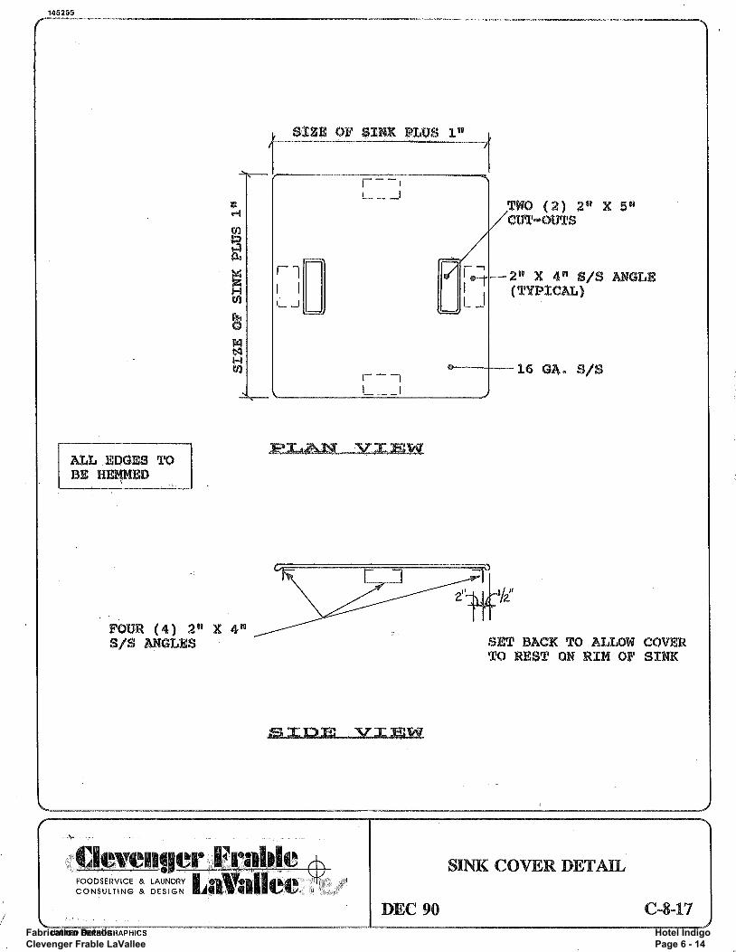
Fabrication Details Clevenger Frable LaVallee
Hotel Indigo Page 6 - 14
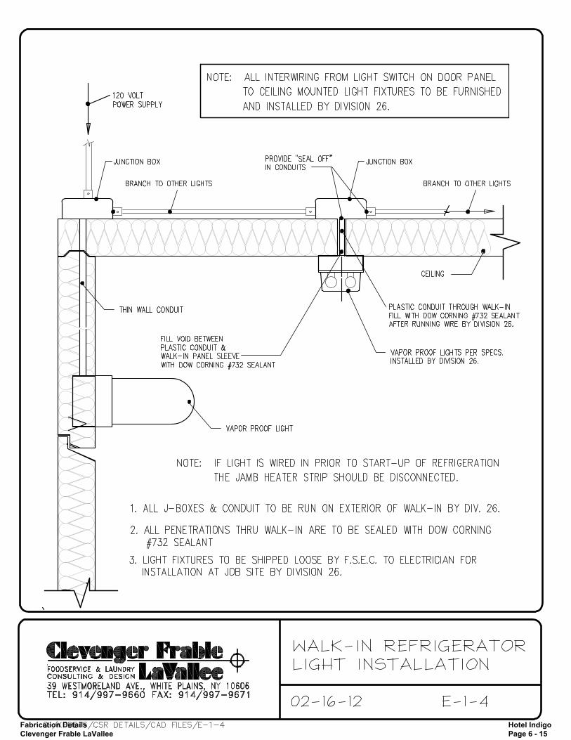
Fabrication Details Clevenger Frable LaVallee
Hotel Indigo Page 6 - 15
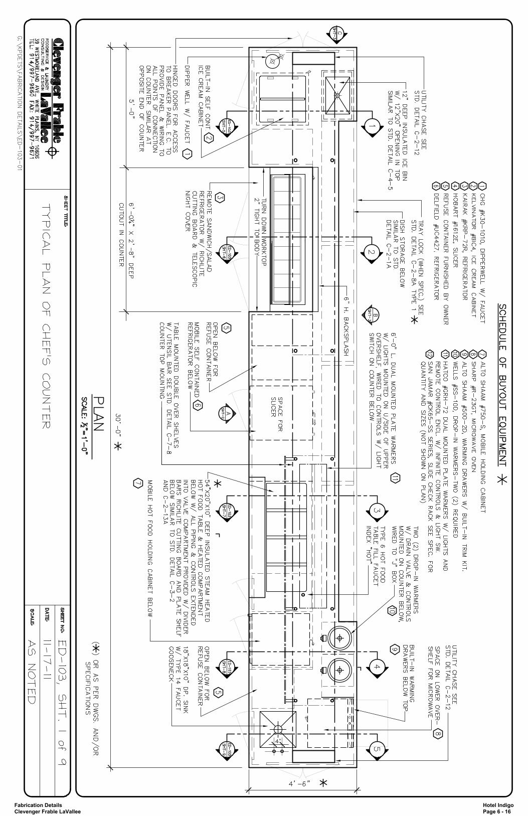
Fabrication Details Clevenger Frable LaVallee
Hotel Indigo Page 6 - 16
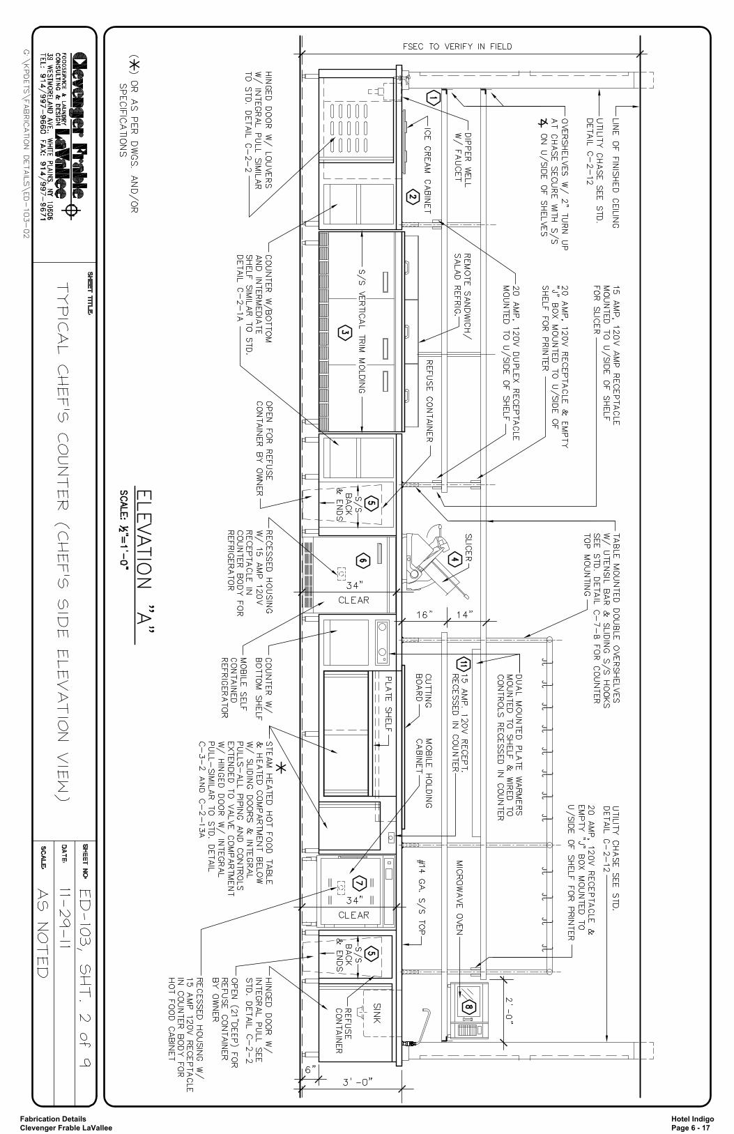
Fabrication Details Clevenger Frable LaVallee
Hotel Indigo Page 6 - 17

Fabrication Details Clevenger Frable LaVallee
Hotel Indigo Page 6 - 18

Fabrication Details Clevenger Frable LaVallee
Hotel Indigo Page 6 - 19
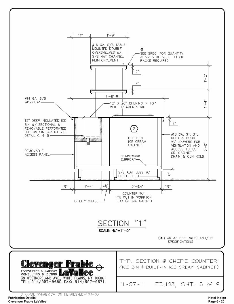
Fabrication Details Clevenger Frable LaVallee
Hotel Indigo Page 6 - 20
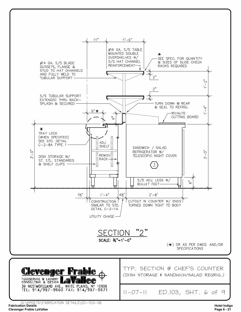
Fabrication Details Clevenger Frable LaVallee
Hotel Indigo Page 6 - 21

Fabrication Details Clevenger Frable LaVallee
Hotel Indigo Page 6 - 22
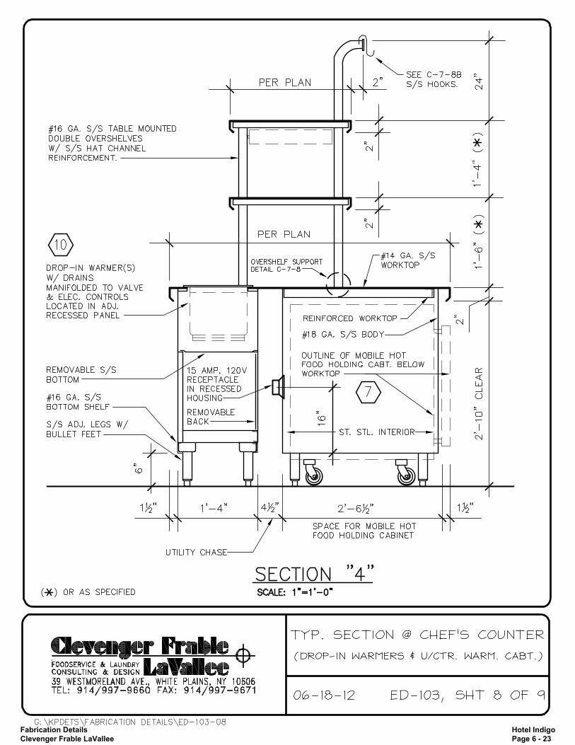
Fabrication Details Clevenger Frable LaVallee
Hotel Indigo Page 6 - 23

Fabrication Details Clevenger Frable LaVallee
Hotel Indigo Page 6 - 24