HOT ROLLING OF COMMERCIALLY PURE TITANIUM AND … · WATERTOWN ARSENAL LABORATORIES TITLE HOT...
55
Titanium, processing in fabrication Rolling - titanium HOT ROLLING OF COMMERCIALLY PURE TITANIUM AND TITANIUM ALLOY Ti-6A1-4V Technical Report No. WAI, TR 401.5/3 BY Eugene DiCesare Date of Issue - December 1961 Om. Code 5010.11.8420051 Research of Materials for Lightweight Construct ion D/A Project 593-32-003 WATEmW ARSENAL WATEWTOWN 7 2. MASS.
Transcript of HOT ROLLING OF COMMERCIALLY PURE TITANIUM AND … · WATERTOWN ARSENAL LABORATORIES TITLE HOT...

Titanium, processing i n fabr icat ion
Rolling - titanium
HOT ROLLING OF COMMERCIALLY PURE TITANIUM AND TITANIUM ALLOY Ti-6A1-4V
Technical Report No. WAI, TR 401.5/3
BY
Eugene DiCesare
Date of Issue - December 1961
O m . Code 5010.11.8420051 Research of Materials f o r Lightweight Construct ion
D/A Project 593-32-003
WATEmW ARSENAL WATEWTOWN 7 2. MASS.

WATERTOWN ARSENAL LABORATORIES
TITLE
HOT ROLLJNG OF COMMERCIALLY PURE TITANIUM AM3 TITANIUM ALLOY ~ i - 6 ~ 1 - 4 ~
ABSTRACT
Rolling forces and torque were experimentally determined i n ho t r o l l i ng commercially pure t i tanium and t i tanium 6~1-LV alloy on a 2-high experimental r o l l i n g mill with 5-1/4" 0. D. r o l l s . Rolling temperatures were 1400 F, 1600 F, 1800 F, and 2000 F, specimen widths l", 2", and 4", and specimen thicknesses 1/32", 1/16", and 1/8 I t .
Results are presented i n the form of curves showing the effects of - reduction, r o l l i n g temperature, specimen s ize , and a l loy on roll sepa-
r a t i ng force , spec i f i c pressure, horsepower and work, forward s l i p , lever arm r a t i o and spread.
Mechanical Engineer
APPROVED :
0.b &-, 4. F . SULLIVAN
rec tor Arsenal Laboratories

CONTENTS
Page ABSTRACT
. . . . . . . . . . . . . . . . . . . . . . . . . . . . INTRODUCTION 3
. . . . . . . . . . . . . . . . . . . . . . MATERIALS AND PR0CF;DURE: 3 . . . . . . . . . . . . . . . . . . . . . . . . . Test Specimen 3
. . . . . . . . . . . . . . . . . . . . . . . . . . . . T a b l e 1 4 . . . . . . . . . . . . . . . . . . . Equipment and Procedures 4
. . . . . . . . . . . . . . . . . . . . . RESULTS AND D I S C U S S I O N S '. 5 R o l l Separating Force and Specif ic Pressure . . . . . . . . . . 6
Horsepower and Work . . . . . . . . . . . . . . . . . . . . . . 8 . . . . . . . . . . . . . . . . . . . . . . . . . . Forward S l i p 9 . . . . . . . . . . . . . . . . . . . . . . . . Lever A r m Ra t io 9
Spread . . . . . . . . . . . . . . . . . . . . . . . . . . . . . 10 . . . . . . . . . . . . . . . . . . . . . . . . . . . . CONCUTSIONS 10
ILUTSTRATPONS . . . . . . . . . . . . . . . . . . . . . . . . . . i 1 2
APPENDIX

INTRODUCTION
The ro l l i ng of metals, one of the most common fabr ica t ion processes, has been the subject of considerable research. Theories of r o l l i ng have attempted t o explain the ro l l i ng process; however, the theor ies are not suf f ic ien t ly advanced t o adequately explain and predic t r o l l i ng phenomena. There i s a lso a lack of experimental data, pa r t i cu l a r l y i n ro l l i ng t he newer metals such a s titanium.
Since titanium, due t o i t s unique charac te r i s t i cs , presents problems i n ro l l ing , experimental data r e l a t i v e t o force and power requirements would be valuable f o r use i n designing r o l l i n g mills , analys is of the ro l l i ng process, and f o r the spec ia l case of thin-sheet ro l l ing .
The r e s u l t s presented herein are a continuatton of work previously 1 reported , i n which r e s u l t s were presented f o r titanium, al loys, Ti-7SA,
RC - l3OA, ~ i - 6 ~ 1 - 4 ~ , and RG-130B.
A l l da ta presented a r e f o r commercialLy pure t i tanium and t he t i t a - nium 6~1-LV al loy. Experimentally measured r o l l separating force and torque values f o r varying reductions, specimen widths and thicknesses, and ro l l i ng temperatures were used t o ca lcu la te specif ic pressure coxrected f o r r o l l deformation, horsepower, work, forward s l i p , l ever arm ra t io , spread, and r a t i o of f i n a l thickness t o r o l l diameter.
MATERIALS AND PROCEDURE;
Test S~ecimens
Test specimens were commercially pure t i tanium and t i tanium 6 ~ 1 - 4 ~ alloy, I", 2", and 4" wide and 1/8", 1/16", and 1/32" th ick by 6" long. A l l specimens .were sheared longi tudinal ly from large sheets and the edges surface ground t o the specif ied width.
Mechanical proper t ies and chemical analyses submitted by the producere are shown h Table I.
Some discrepancies may be noted i n the mechanical propert ies, pa r t i cu l a r l y i n t he t h i n section, The reason f o r t h i s i s not known. The high hardness of t h e t h i n sect ions may be due t o the thinness of t he specimen.

TABLE I
Mechanical Proper t ies
Yield Tensile S t r e n ~ t h
Strength (0.02% off s e t ) ( p s i ) ( p s i )
Chemical Analyses
C - N - Fe - A 1 - v - H - Mn - Comm. Pure Titanium 0.10 0.016 0.30 -- - - - - -- ~i -6~1-4v 0.01 0.014 0.15 6.2 3.7 0.003 0.04
Equipment and Procedures
The t e s t equipment and procedures a re described i n a previous report.' Briefly, specimens were heated i n a muffle-type furnace for one hour, re- moved with heated tongs and ro l l ed a t three-minute i n t e rva l s through un- heated r o l l s . On leaving the r o l l s the specimens were guided through a chute into a water-guench tank t o r e t a i n the as-rolled structure.
The ro l l i ng m i l l was a 2-high/4-high experimental mill used as a 2-high mill, and was equipped with s t r a i n gage load c e l l s and torque arms. The load cells a re described i n Reference 1. The torque arms (Figure 1) replaced the top and bottom dr ive sha f t s and u t i l i z e d a similar amplFfier and recorder system.
Specimen thickness and width before and a f te r r o l l i ng was measured wi th a micrometer t o 0.001". Forward s l i p measurements were made t o 0.01" with an engineer's scale.

Roll separating force, torque, and s l i p measurements were u sed - to calcula te the data f o r the curves. Formulae, calculat ions, and def in i - t ions of terms are presented i n Appendix A.
RESULTS AND DISCUSSIONS
I n ro l l i ng sheet material , the i n i t i a l thickness of t h e sheet i s Important. As t he thickness decreases t he ro l l i ng preasure increases and t he l i m i t of r o l l a b i l i t y i s approached f o r a m i l l of given capacity. This l im i t a t i on may be expressed by the formula f o r average ro l l i ng pres- Sure
wherein it may be seen t h a t Pax i s dependent upon the yie ld s t rength 07%- of t he material , coef f ic ien t o f f r i c t i o n p, contact length L, and material thickness h, The r o l l i n g l i m i t i s approached when the average ro l l ing pressure i s not g rea t enough t o produce fu r ther p l a s t i c deformation of the mater ia l but only deformation of t h e r o l l s .
Rolling metals a t elevated temperatures permits greater reductions due t o the lower y i e ld s t reng th and change i n coef f ic ien t of f r i c t i o n be- tween the sheet and the r o l l s , This i s a l s o t r ue f o r titanium; however, high temperature r o l l i n g of titanium a l so introduces the problem of sur- face contamination and s i z e and f l a t n e s s var ia t ions . When ro l l i ng t i t a - nium, these and other f a c t o r s must be considered; however, these problems are not per t inent t o t h i s work.
I n addi t ion t o t h e above, t he power consumption i s an important con- s iderat ion. The power required f o r rolling i s dependent upon t he magnitude and loca t ion of the v e r t i c a l r e su l t an t of the applied ro l l i ng load. These are determined by several interdependent f ac to r s including r o l l diameter, material s i ze , angle of contact , specimen res is tance t o deformation, and f r i c t i o n conditions within the r o l l gap. There i s an increase i n power consumption with increasing r o l l diameter for a constant reduction due t o an increase i n t he contact area, f r i c t i o n , and length of the lever arm.
F r i c t i on condit ions, due t o t he surface condit ion of the r o l l s and sheet materials , and the use of a lubr icant influence the height of t h e f r i c t i o n h i l l and the length of the lever arm, hence t he power consumption.
Thus -it i s apparent t h a t cold r o l l i n g an unlubricated, wide, t h i n sheet of metal with large diameter r o l l s w i l l require more power than hot r o l l i n g a narrow, th icker s t r i p of the same material with smaller diameter r o l l s .
Power requirements i n ro l l i ng may be measured by determining the e l e c t r i c a l power input t o the d r ive motor; however, the method i s somewhat

inaccurate as the ac tua l power expended a t the r o l l s must be ca lcu la ted based on t h e efficiency of the motor and several d r i v e components. A more accurate method i s t o rnea.sure the torque required a t t h e dr ive s h a f t by means of e l e c t r i c a l s t r a i n gages, and from this t o calcula te the horse- power. Only the loss a t the r o l l bearings i s neglected. This l a t t e r method was used f o r t he work reported herein.
I n the following sections, experimental data pertaining t o the above fac tors i n r o l l i n g t i tanium are presented and b r i e f l y discussed. F i r s t , the ro l l i ng load data i s presented together with curves of specif ic prea- sure, Then power data i s presented i n one s e t of curves showing t o t a l power consumption and another showing work per u n i t volume of metal ro l led, indicat ing t he e f f e c t s of several var iables . The remaining sections, covering forward s l ip , laver arm r a t i o , and spread, are important as they indicate the f r i c t i o n a l conditions within the r o l l gap.
Roll Separating Force and Specific Pressure
1. Reduction
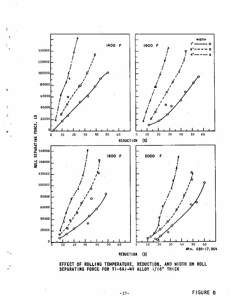
The r a t e of increase i n r o l l separating force was g rea tes t f o r the highest reductions due t o an increase i n res is tance t o deformation by the t i tanium and t o r o l l f l a t t en ing , see Figures 2 through 7.
The curves of specif ic pressure versus reduction a re presented in Figures 8 through 13. By comparing the curves on the bas i s of u n i t widths, specimen width i s seen t o have no e f f ec t on the r o l l separating force . An exception may be noted f o r the 1/32"-thick specimens ro l led a t the highest temperatures. This may be due t o inaccuracies i n measurements caused by t he low reductions and sca le on the surface of the specimens, and t o r o l l ' quenching.
2. Temperatures
~ o l l i ' n ~ temperatures between 1400 F and 2000 F were selected i n order t o r o l l specimens with microstructures ranging from all-alpha t o a l l - beta. It i s evident i n Figures 14 and 15 t ha t the magnitude of the r o l l separating force decreased rap id ly wi th increasing temperatures up t o about 1800 F. I n the al l -beta range (above 1800 F), the e f f e c t of temper- a tu re i s comparatively minor f o r a l l thicknesses i n the commercially pure metal; however, r o l l sgparating forces f o r the th icker sect ions of the 6 ~ 1 - 4 ~ a l l o y continued t o decrease.
The e f f e c t of r o l l quenching i s apparent i n specimens, some of which ac tua l ly require higher perature. This ind ica tes a drop i n the specimen cooling of the t h i n cross section. Data f o r the somewhat inaccurate due t o t h e small reductions, of obtaining accurate thickness measurements.
the t h i n and narrow forces a t the higher tem- temperature due t o rapid th innest sect ions may be scale, and the d i f f i c u l t y

An in t e r e s t i ng indicat ion of the e f f ec t of temperature and r o l l quenching may be seen i n t he curves of reduction versus temperature f o r a constant r o l l separating force, Figures 16 and 17. It i s apparent from the curves t h a t hot r o l l i ng t h i n sections i s not advantageous with respect t o power requirements a s the th innes t sections showed l i t t l e change i n reduction with increasing temperature. I n addition, aurface contamination, s i ze and f l a t n e s s control , g ra in growth, and temperature con t ro l are f ac to r s which make hot r o l l i n g of t h i n sect ions unat t ract ive and suggest why cold ro l l i ng i s normally used.
The appearance of the spec i f ic pressure curves i s comparable t o t h a t of the r o l l separating force curves. O f pa r t i cu la r i n t e r e s t i n Flgure 18 i s t he appreciable drop i n spec i f ic pressure with increasing temperature * f o r a 15% reduction, Exceptions are t he curves fox narrow 1/32"-thick specimens which indicate an increase i n spec i f ic pressur.e f o r these speci- mens a t the high temperatures.
+ 3. Specimen Thickness The curves of Figure 19 of roll separating force versus specimen
thickness f o r a 15% reduction a re in te res t ing because they indicate the e f f ec t of r o l l quenching on t h i n sect ions . R o l l separating forces f o r a
- 15% reduction a re comparable f o r a l l widths o f the 1/8"- and 1/16"-thick specimens, but increase appreciably i n magnitude f o r the 1/32"-thick specimens. This i s most apparent a t high temperatures where t he e f f ec t of r o l l quenching i s g rea t e s t .
I n Figure 18, comparison of the spec i f ic pressure curves a l so shows an increase i n magnitude of the specif ic pressure with decreasing speci- men thickness. T h i s i s due pr imari ly t o increased r o l l deformation caused by a smaller contact area on t he r o l l s and t o an increase i n deformation res is tance of t he th inner sect ion.
4. Specimen Width
I n Figure 20, the e f f e c t of specimen width on reduction i s shown f o r several thicknesses a t a constant r o l l separating force. I n Figures 2 1 and 22, t he r o l l separating force i s seen t o increase l i n e a r l y with the width of the s t r i p , with the slope vary-ing with microstructure and alloy.
The curves of spec i f i c pressure shown i n Figures 8 through 13, based on a u n i t width, are e s sen t i a l l y i den t i ca l f o r a l l widths with the excep- t i o n of the l/3 2"-thick specimens of commercially pure t i tanium ro l led a t 1800 F and 2000 F. A s noted i n paragraph 2, above, on Temperatures, t h i s may be due t o r o l l quenching and inaccurate thickness measurements r e - su l t ing from small reductions, scale on the specimens, and var ia t ions i n . f i n a l thickness within the specimens.

5. Alloy
Roll separating forces f o r the t i tanium a l l o y 6A1-4V are gener- a l l y higher than f o r t he commercially pure t i tanium due t o t he higher y i e ld s t reng th of t he former.
Higher spec i f i c pressures f o r the a l l o y t i tanium are i n agreement with the r o l l i n g load curves. An appreciable reduction i n specif ic pres- sure, f o r the th icker sections of a l l oy titanium, r e s u l t s from increasing r o l l i n g temperatures.
Horsepower and Work
1. Reduction
The curves of Figures 23 through 26 show that horsepower con- sumption increases moderately while work per u n i t volume of ro l l ed metal increases sharply a s the maximum reduction i s approached, The di f ference i s due t o the work expended i n deforming t he rolls, resu l t ing i n l e s s reduction of the specimen per horsepower input. 1
The r a t e of increase i n work f o r the 1/811-thick ypecimens also shows the e f f e c t of r o l l quenching and res is tance t o deformation. A t t he higher reductions and temperatures the slopes of the curves increase rapidly, and are comparable t o the slopes fox the thinner specimens. For low reductions and temperatures, r o l l quenching i s l e s s e f fec t ive due t o t h e smaller contact area between the specimen and the r o l l s . Resistance t o deformation i s a l so lower, due t o the l e s s e r reductions.
2. Temmrature and Specimen Thickness
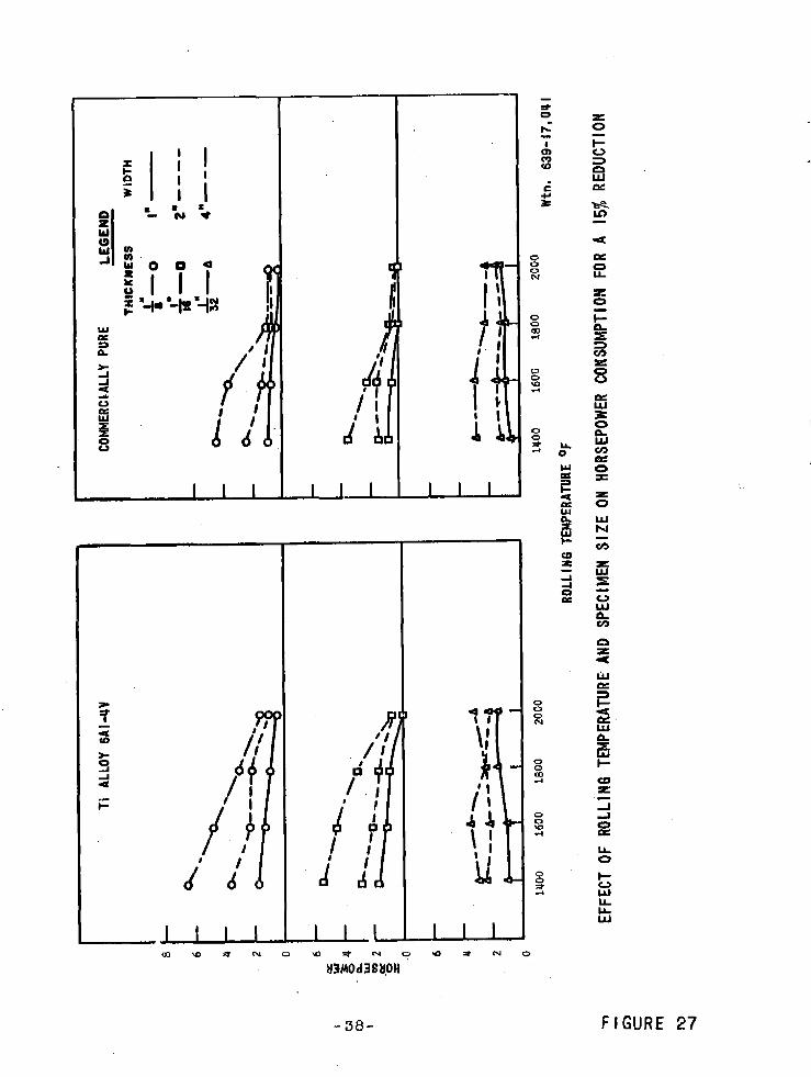
The curves i n Figures 27 and 28 show t h a t horsepower requirements f o r a given reduction were general ly lower with increasing temperature and that work per unlt volume showed a s imilar t rend i n t he th icker sections. For comparable reductions there i s l i t t l e d i f ference i n horsepower with decreasing specimen thickness a s contrasted t o the e f f e c t on work. Work shows an appreciable increase per u n i t volume a t a l l temperatures, Figures 23 through 26. This i s due t o the approaching limit of r o l l a b i l i t y , with an increased proportion of t he work going i n t o deformation of t he r o l l s and l e s s i n to deformation of the metal being rol led.
I n Figure 29 t h e curves of reduction versus temperature f o r a con-
s t a n t value of work of 55,000 * are in te res t ing . These indicate an in-'
increased reduction In the th icker specimens, resu l t ing from an increase . i n r o l l i n g temperature, as contrasted t o a small decrease i n reduction f o r the 1/3211-thick specimens, This i s due t o r o l l quenching and the , 7
higher res i s tance t o deformation of t h e t h i n specimens. This effect is a l so apparent i n t he curves of Figure 28 which show a subs tan t ia l increase i n work required f o r the 1/32"-thick specimens as compared t o a decrease 3
f o r the thicker specimens with increasing temperature.

3 . Specimen Width
Figures 23 through 26 indicate t ha t horsepower requirements i n - crease approximately l i n e a r l y with increasing specimen width, while work, based on unit volume, i s comparable f o r a l l widths of specimens.
4. Alloy - Both horsepower and work per u n i t volume are greater i n magni-
tude f o r the t i tanium a l l oy due t o t h e higher y ie ld s t rength of t he al loy.
Forward S l i p
'1. Reduction
An indicat ion of one of the important f ac to r s i n the r o l l gap, t he coeff ic ient of external f r i c t i o n , i s given by forward s l i p maasure- m n t s , a high forward s l i p indicat ing a high coef f ic ien t of f r i c t i o n . A s noted e a r l i e r , f r i c t i o n helps determine the r o l l i n g load and power require- ments i n ro l l ing .
I n Figures 30 and 31 forward s l i p increases with reduction, the r a t e of increase being grea te r a t high reductions. The accuracy of forward s l i p measurements was influenced by scale and d i s to r t i on on t he specimen so t h a t s ca t t e r i s noted i n t h e data.
2. Temperature
For a constant reduction, Figure 32 shows t h a t forward s l i p gen- e r a l l y decreases with increasing temperature, indicat ing a decreasing coeff ic ient of f r i c t i o n .
3 . Specimen Thickness
Figure 32 shows t h a t the forward - s l i p increases with decreasing i n i t i a l specimen thickness.
4. Specimen Width
The e f f ec t of specimen width on forward slip i s negligible.
5. Alloy - Forward s l i p i s comparable f o r both groups, indicat ing the co-
e f f i c i e n t of f r i c t i o n i s e s sen t i a l l y the same f o r the commercially pure t i tanium and the 6 ~ 1 - 4 ~ a l loy.
Lever A r m Ratio
1. Reduction
The l eve r arm r a t i o i s the r a t i o of t h e distance a t which t he r o l l i n g load ac t s t o the length of the contact arc. It i s an indicat ion of t he no-sl ip point o r zone and the point a t which the resu l tan t of the r o l l i n g load acts, and i s usua l ly below 0.5. The l ever arm and the

r o l l i n g load determine power consumption i n rolling. Figures 33 and 34 show a decrease i n lever . arm r a t i o with increasing reduction.
2. Other Variables
a. The magnitude of the lever arm r a t i o i s e s sen t i a l l y unaf- fected by the ro l l i ng temperature.
b. The lever arm r a t i o i s generally lower with decreasing speci- men thickness.
c. Specimen width does not a f f e c t the lever arm r a t i o .
d. The lever arm r a t i o i s comparable f o r both t he a l l oy and the commercially pure specimens.
Spread
Curves shoving the increase i n specimen width, o r spread, with r e - duction a r e presented i n Figure 35. These show that spread increases with increasing reduction, r o l l i n g temperature and ipecimen thickness and decreases with increasing specimen width. This i s due t o t he decrease i n res is tance t o metal flow offered by the thick, narrow. specimens a t e le - vated temperatures. The spread i s comparable in magnitude f o r both the a l l oy and the commercially pure t i tanium.
1. Roll separating forces and spec i f ic pressures - a. Increase with reduction. The former increases nonlinearly, witk
the grea tes t increase a t the high reductions. The increase i s generally l i nea r f o r spec i f i c pressures.
b. decrease with increasing ro l l i ng temperature, generally most . ~ a p i d l y f o r temperatures below the a l l -beta range of approximately 1800 F. However, r o l l quenching r e s u l t s i n higher r o l l separating fo rces f o r the thin, narrow specimens a t high temperatures.
c. are higher f o r the a l l o y titanium due t o the higher y ie ld strength.
2. Horsepower and work per unit volume - a. increase with reduction. The l a t t e r increases a t the higher rate
due t o an increase i n work expended i n r o l l deformation.
b. increase with decreasing specimen thickness. The la t t e r increases at the higher r a t e .
c . decrease with increasing ro l l i ng temperature f o r t he 1/8"- and 1/16"-thick specimens but increase f o r the l / j2"- thick specimens due t o r o l l quenching. .+
d. a re g rea te r f o r the a l l oy than f o r the commercially pure titanium.

3. Forward s l i p - increases with reduction and decreases with increasing specimen
thickness and rolling temperature. It i s not affected by specimen width or alloy.
4. Lever arm r a t i o -
decreases with increasing reduction and increases with increasing specimen thickness. Rolling temperature, specimen width and al loy do not a f fec t the lever arm ra t io .
5. Spread -
increases with reduction, rolling temperature, and specimen thick- ness. Spread i s comparable f o r both the alloy and- the commercially pure titanium .

TORQUE ARM - SAE 1020 S)TEEL
SR4 STRAIN GAGE LOCATIONS
-1 OUTPUT
b INPUT . - I WIRING DIAGRAM
SCHEMATIC OF TORQUE MEASURING ARMS FOR EXPERIMENTAL ROLLING MI LL
FIGURE I

REDUCTION ( f l
REDUCT l ON ($1 Wtn. 639- I?, 053
EFFECT OF ROLLING TEMPERATURE, REDUCTION AND WIDTH ON ROLL SEPARATING FORCE FOR COMMERCIALLY PURE TITANIUM 118" THICK
F IGURE 2

Wtn. 639- 17,062 REDUCT l ON ($1
EFFECT OF ROLL l NG TEMPERATURE, REDUCT I ON, AND W l DTH QN-ROLL SEPARATINO FORCE FOR COMMERCIALLY PURE T I T A N I U M 1 / 1 6 " THICK
FIGURE 3

EFFECT OF ROLL l HG TEMPERATURE, REDUCT I-OH, AND W l DTH OW ROLL SEPARAT l NG FORCE FOR- COMMERCIALLY PURE TITANIUM 1/32" THICK

-.
- WIDTH 1"- t - 4"-- - r * " i P
/ 0' I - 1600 F
-
2 I 1 1 1 1 1 1 I 1 1 1 - 0 10 20 30 40 50 60 70 0 10 20 30 40 50 60 7 0
5 n! REDUCT I ON ($1
Wtn. 639- 17,066 REDUCTION ( j )
EFFECT O F ROLL1 NG TEMPERATURE, REDUCTION, AND SPECIMEN Wl DTH ON ROLL S E P A R A T I N G FORCE FOR Ti-6Al-4V ALLOY 1/8" TH ICK
FIGURE 5
WIDTH
1600 F I"------ 0 2"-- - - 0
7 4*--- A
REDUCT l OH ($1 I I I
Wtn. 639- 17, Q6P REDUCT l ON ($1
EFFECT OF ROLLING TEMPERATURE, REDUCTION, AND WIDTH ON ROLL SEPARATING FORCE FOR Ti-6AI -UV ALLOY I / 16" TH l CK
FIGURE 6

REDUCTION ($1
REDUCT \OH ($1 Wtn. 639- 17,062
EFFECT OF ROLL1 NG TEMPERATURE, REDUCTION .AND W l DTH ON ROLL. SEPARATING FORCE FOR T i - 6 A I -4V ALLOY 1/32" T H l CK
- 18- FIGURE 7

EFFECT OF ROLLING TEMPERATURE, REDUCTION AND WIDTH ON SPEC1 F l C PRESSURE FOR COHMERCI ALLY PURE TITAN lUM 118" TH l CK
F IGURE 8

V) 0 10 20 30 40 50 60 70 W P: n REDUCT l ON (5)
Wtn. 639- 17,056 REDUCT l ON ($1
EFFECT OF ROLLING TEMPERATURE, REDUCTION, AND WI DTH .ON SPEC1 FI C PRESSURE FOR COMMERCIALLY PURE TITANIUM I / 16" TH l CK
F IGURE 9

EFFECT OF ROLLING TEMPERATURE, REDUCTION, AND WIDTH ON SPEC1 F l C PRESSURE FOR COMMERCIALLY PURE TITAN IUM 1/32" TH l CK
F I G U R E 10

REDUCTION ($1
100000
eoooo
60000
40000
20000
Ytn. 639- 17,065 REDUCT l ON ($1
EFFECT OF ROLLING TEMPERATURE, REDUCTIQN, AND WIDTH ON SPEC1 F l C PRESSURE FOR Ti-6A I -4V ALLOY I /8" TH l CK
FIGURE I I

V)
,* 60000 w 3 r l ~ l ~ l r l i l ~ l i ~ vr VI 0 10 20 90 40 50 60 UJ a: REDUCT l OH
EFFECT OF ROLLINO TEMPERATURE, REDUCTIQN, AND WIDTH ON SPEC1 FlC PRESSURE FOR Ti-6AI-4V ALLOY 11 16' THICK
- 23- FIGURE 12

400000 WIDTH
EFFECT OF ROLLING TEMPERATURE, REDUCTIQN, AND WIDTH ON SPEC l F l C PRESSURE FOR T I-BA I -UV ALLOY 1/32'' TH l CK
- 24- FIGURE 13

C O M M E R C I ALLY ? U R E
REDUCTION 15% LEGEND
THICKNESS WIDTH
Wtn. 639- 17, 1 18 ROLLING TEMPERATURE, OF
EFFECT OF ROLL1 NG TEMPERATURE AND SPEC1 MEN S l ZE ON ROLL SEPARATING FORCE
F I G U R E I 4

LEGEND THICKNESS WIDTH
I"-o 8 I" , -
T i ALLOY 6~1-uv
REDUCTION = 15%
Wtn. 639- 17, 118 ROLLINO TEMPERATURE OF
EFFECT OF R O L L I N G TEMPERATURE AND SPECIMEN SIZE ON ROLL S E P A R A T I N G FORCE
- 26- FIGURE 15

LEGEND COMMERC I ALLY PURE
ROLL SEPARATING
ROLL1 NO TEMPERATURE OF
EFFECT OF ROLLING TEMPERATURE AND SPECIMEN S l ZE ON PERCENT REDUCTION
- 27- F I G U R E 16

T i ALLOY 6AI-UV
LEGEND THICKNESS t"lIDTI-4
ROLL SEPARATING FORCE
-
Wtn. 639- 17,048
ROLLl N G TEMPERATURE OF
EFFECT OF ROLLl NG TEMPERATURE AND SPECIMEN S I Z E ON PERCENT REDUCTION
- 29- F I G U R E 17

T i ALLOY G A I - Y V COMMERC l ALLY PURE
REDUCTION, = 15%
Wtn. 639- 17,046 ROLLING TEMPERATURE OF
EFFECT OF ROLL1 NG TEMPERATURE AND SPEC1 MEN S IZE ON - SPEC1 FI C ROLL1 NG PRESSURE
FIGURE 18

140000
i Ti-6A1-UV ALLOY 120000
100000
BOO00
~ ! 1 2 0 0 0 0 ~ - E L ' 4. 4 Ti-CAI-UY ALLOY & l00000 , 1900 F
vr 'i \, = 80000 - 0 E
60000
40000
20000 , ----'*
0, , 1 I I t
T i -6AI-4V ALLOY p Z O O 0 F
t COMMERCIALLY PURE
80000 COMMERC l ALLY PURE
6000 la00 F
- COKHERCIALLY PURE
- ZOO0 r
- -
0 . 0 3 8 0 060 0.090 0.120 0.030 0.060 0.090 0.120 0.030 . 0.060 0.090 0.120 0.030 0.060 0.090 0.120
!Jtn. 639- 17,075 I X l T l A L SPECIMEH THICKNESS, 1H.
EFFECT OF INITIAL SPECItjENS THICKHESS, WIDTH, AND ROLLING TEMPERATURE OH ROLL SEPARATIKG FORCE FOR A 15% REDUCTION

F I G U R E 20

COMMERC l ALLY PURE - LEGEND
THICKNESS
- REDUCTION = 22.5%
TEMP. F
1400
1600 --A-
I800 - - 2000 - -
Wtn. 639-~17,050
SPECIMEN WIDTH, IN.
EFFECT O F R O L L I N G TEMPERATURE AND SPECIMEN W l DTH ON ROLL SEPARATING FORCE
FIGURE 21

T i 6AI-9V ALLOY - L'EGEMO
THICUWESS TEMP. .F
I -T 1400 -
REDUCTI ON = 22.5% IS00 ---- I€lOO -- - 2 0 0 0 - -
I
C
r
Wtn. 639- 17,099 SPECIMEN WIDTH, IN.
EFFECT OF ROLL1 NG TEMPERATURE AND SPEC l MEN Wl DTH ON ROLL SEPARATING FORCE
F I G U R E 22

0 10 20 30 40 ,50 60 70 0 10 20 30 40 50 60 70 REDUCTION ( f l
eooo F
1 / 8 " THICK
0 10 20 30 40 50, 60 70
Wtn. 639- 17,058
EFFECT OF ROLLI NG TEMPERATURE, REDUCTION, AND SPECIMEN S l f E ON HORSEPOWER CONSUMPTI ON FOR COMMERCI ALLY PURE T l TAN l UM
FIGURE 23

EFFECT OF ROLL1 NO TEMPERATURE, REDUCT ION, AND I W I T 1 AL TH l CKNESS OH WORK PER UNIT VOLUME FOR COMMERCIALLY PURE TITAN lUM I " W l DE
-35- FIGURE 24

12 , 1/16'' T H l C K
- 4C 1/32" THICK
P 1/16' T H l C K
1/32" T H l C K
I l l l , l l l 0 10 20 30 YO 50 60 70
0 a w REDUCTI ON V)
1/8" T H l C K A 118" THlCK
- - -
1 / 3 2 " THlCK
EFFECT OF ROLL1 NG TEMPERATURE, REDUCTION, AND SPECIMEN S l ZE ON HORSEPOWER CONSUMPTI ON FOR Ti-6AI -4V ALLOY
-36- FIGURE 25

EFFECT OF ROLLING TEMPERATURE, REDUCTION, AND SPECIMEN THICKNESS ON WORK PER U N I T VOLUME FOR Ti-6AI-VV ALLOY I n WIDE
-37- FIGURE 26
I I Ti ALLOY 6AI-UY COMERC I ALLY PURE LEGEND
THICKNESS WIDTH
L~- * 8 l a -
1100 1600 1800 2000 Wtn, 639-17,041
ROLLIH6 TEMPERATURE OF
EFFECT OF ROLL1 HG TEMPERATURE AND SPEC I MEN S l ZE OH HORSEPOWER COWSUMPTI ON FOR A 15% REDUCT! ON

C ~ ~ E R C I ALLY ruuE
W l O E THICK
ROLLING TEMPERATURE, OF
I- T l ALLOY 6A1-YV
1400 1600 la00 2000 Wtn. 639-1
ROLLINO TEMPERATURE, OF
EFFECT O F ROLLING TEMPERATURE AND S IZE ON WORK PER UNIT VOLUME FOR A 15% REDUCTION
FIGURE 28

COMMERCI ALLY r U R E TITANIUM
I N-LB WORK 59,000 -7
I T i 6A1-4V ALLOY
1400 1600 1800 2000 Wtn. 639- 1 7 0 W P
R O L L I N G TEMPERATURE, OF
EFFECT OF ROLLING TEMPERATURE AND SPEC l MEN TH l CKNESS ON REDUCTl ON
- 40 F I G U R E 29

W h . 639- 17,073 REDUCTION (k)
EFFECT OF ROLL l NG TEMPERATURE, REDUCTION, AND SPECIMEI S l ZE ON FORWARD St. l P FOR COMMERC t ALLY PURE T f TAN l UM

EFFECT OF ROLL! HG $ 1 ZE OH FORWARD Sl
TEMPERATURE, REDUCTION, A I D SPECIMEN I P FOR T i 6A1-UV ALLOY

REoucflon 90% WIDTH = 1 "
0 l Y 0 0 1600 N O 0 2000
ROLLING TEMP. OF
ROLLING TEMP- OF Wtn. 639- 17,043
EFFECT OF ROLLING TEMPERATURE AND SPEC1 MEW TH l CKNESS ON FORWARD SLl P
FIGURE 32

.a '
.7 - 1400 F
.6 - l / E n T H I C K
1/16" T H I C K
1/32" T H l C K
1 / 1 6 ' T H I C K
1132* T H l C K
1 / 3 2 " T H l C K
f , mT..p, , , . 2
.I 0 10 20 30 40 50 6 0 70
1 . 1/16" T H l C K
EFFECT OF ROLL1 NG TEMPERATURE, REDUCTION, AND SPECIMEN SIZE ON LEVER ARM RATIO FOR COHMERCIALLY PURE T I T A N I U M
-44- FIGURE 33

\ ' 6 - \ . 5 - .4 - . 3 - - 2 - 1/8" THICK 118' THICK I
" 'x * \,\. - ':\- - - 1/8* THICK
1/16' THICK ', . 3 " - b
. 2 4
* * I- - 1/32* THICK
REDUCTION (a EFFECT OF ROLL! NG TEMPERATURE, REDUCTION, AND SPEC lMEN S I Z E ON LEVER ARM RATIO FOR Ti-GAI-UV TITANIUM
F I G U R E 34

3 1400 C
T i 6 A 1 - 4 V ALLOY - 1 1/8" T H l C K
1 2/32' T H I CK I
COMMERC l ALLY PURE
z z -I- 3
1/32" T H l C K -,
O r nr.da6owo, I 1 I r I . I 4 I 8
0 10 20 30 40 50 60 70 80
WIOTY I.-- O ,,,, , T i G A I - r l V - O ALLOY .
a " 1/32" T H I C K
, l , l , l , l ,
0 10 20 30 40 50 60 70
C O M M E R C I A L L Y PURE P I
- 1/16" T H l C K
EFFECT OF ROLLING TEMPERATURE, REDUCTION, AND SPECIMEN S I Z E ON SPREAD
-46- FIGURE 35

APPENDIX A
CALCULATIONS
1. Specific Pressure D
Correct f o r r o l l deformation as follows:
a. Determine PS
b. Determine % change i n I, from Figure A-1, Appendix A f o r Ps and h, - hf.
I d. Determine % change i n L f o r Ps ( ~ i ~ u r e 1 )
-
e. Calculate new L' = (1 * - L ) ~ L I I
f . Calculate P = P, bmL
g. Determine new PSI and L' by tr ial-and-error u n t i l P equals the measured r o l l separating force . PS1 i s then spec i f ic pressure corrected f o r r o l l deformation,
2. Forward S l i p
I- f 3. Lever Arm Rat io = g
where 4 a T~ P
4. Percent Reduction = ho - hf
h, x 100
5. Horsepower
6. Work per U n i t Volume of Metal Rolled
Work calcula t ions were based on conditions a t t he no-slip point o r the center of a no-sl ip zone during ro l l ing and were made as follows:
, 33000 Hp Work per u n i t volume - vmbmhm

It was assumed tha t the specimen wfdth a t the no-slip point (h) was the average of the i n i t i a l and f i n a l widths. A s the change i n width was small, the er ror was negligible.
The veloci ty of the specimen a t the no-slip point was the same as that of the r o l l s , vm = 30 fpm.
Calculation of specimen thickness a t the no-slip point was based on the lever arm r a t i o and the i n i t i a l and f i n a l thicknesses according t o the following r a t i o :
Specimen t h i c h e s s a t the no-slip point, h, = h, + h f j therefore
Horsepower was calculated from the experimental. torque data.

D E F I N I T I O N OF SYMBOLS
L Contact length f o r r i g id r o l l , in . = JRhh
L' Contact length corrected f o r roll deformation, in .
Lf hver arm, i n .
R Roll radius, 2.623 in .
h, Entering t h i c h e s s , in.
hf Exit thickness, in .
Ah Reduction i n t h i c h e s s , in .
hm Thickness a t no-slip point, i n ,
hx Difference between specimen thickness a t the no-slip point and the .exit
b, Average width, in .
P, Specific r o l l p r e s s u r e , p s i
P:, Specific r o l l pressure corrected f o r roll deformation, pai
P Roll separating force, l b
So Distance between punch marks on r o l l , in .
Sf Distance between marks on surface of rolled specimens, in .
T,, Average torque, in-lb
Tt Total torque, in- lb
v, Linear velocity of specimen a t the no-slip point = r o l l surface speed, = 30 fpm

1. LARSON, F . R . , and NUNES, J . , -The Effect of Reduction and Temperature Upon Roll ing Load, Spread, and Forward S l i p In the Hot Rolling of Titanium and Titanium Alloys, Watertown Arsenal Laboratories, WAL TR 401/294, March 1958.
2. LARKE, E. C., The Rolling of Metals and Alloys, Sheet Metal Indus- tries, October 1953 to July 1946 inclusive.
3 UMlERWOOD, L. R., The Rolling of Metals, John Wiley and Sons, Inc . , New York, V. 1, 1950-
4. STONE, M. D., -Rolling of Thin Strip, Iron and Steel Fhgineer, February 1953, p. 61-74, and December 1956, p. 55-76.

WATERTOWN ARSENAL WAT'EFCCOWN 72j MASSACIIIISETTS
TECHNICAL REPORT DISTRIBUTION
b p r t No, t WAL TR 401 .5/3 T i t l e t Hot Rol l ing of Commercially Pure December 1961 Titanium and Titanium Alloy
~ i - 6 ~ . 1 - L V
Distribution List approved by Ordnancs Materiala Research Office, . ~
1 December 1960
Connnander, Armed Services Technical Information Agency, Arlington Hall Station, Arlington 12, Virginia ATTNt TrnR
Director, Army Research Office, Department of the ArrPgt, Washington 25, D L C .
Commanding Officer , Army Research O f f i ce (Durham), Box CM, Duke Station, Durham, North Carolina ATTNc ORDOR-ED
Chief of Ordnance, Department of the Arnpr, Washington 25, D. C. ATTNt ORDTB, Materials
Cormahding General, *.berdeen Proving Ground, Mawland ATTNt ,Ballistic Research Laboratory
ORDBE-LM, Technical Library, h i l d i n g 313
Commanding General, Army Ballistic Maai le Agency, Redatone Arsenal, Alabama ATTNt Dr. G. H. Reisig
Commanding kneral , Ordnance Tank-Antomotive Command, Detro i t Arsenal, Center Line, MLchigan ATTNt ORDMC-RM.1, Mr. Charles Salter
Commanding Cieneral, Ordnance weapons Command, Rock Island, IUinoie ATTN t ORDOW-IX
ORDOW-TX
Commafiding General, U . S. A r v Command, Dover, New Jersey
Ordnance Special Weapons Anma;mitf on

No. of - Copies TO
Commanding General, U. S . Army Rocket and Guided Mfaaile Agency, Redstone Arsenal', Alabama - +
A.TTN : ORDAB-D V ORDXR-RGA, Mr. R. L. Wetherington ORDXR-RMO, L t . E. J . Wilson
Commanding Officer, Detroit Arsenal, Center Une, Michigan A,TTN : ORDMX-Bll'W
ORDMX-AL
Commanding Officer, Diamond Ordnance Fuze Laboratoriea, Washington 25, D . C . ATTNt ORDTL .Ol'2, Technical Reference Branch
Connnanding Officer , Frankford Araenrrl, Phlladelphla 37, Pennay1vanl.a ATTN; Pitmqn-Dzum Laboratories
Commanding Officer, Ordnance Materials Rsaearch Office, Watertown Arsenal, Watertown 72, Maaaachuaettk ATTN r RPD
Commanding Officer, Picatinny Arsenal, Dover, New Jersey ATTNI Feltman Reaearch Laboratories
Commanding Officer, Rock Ialand Araenal, Rock Island, Il l inoia ATTN: Laboratory
Commariding Officer, Springfield Armory, Springfield 1, Maeaachueette ATTN t O R D ~ -TX
Commanding Officer, Watervliet Arsenal, Watervliet, New York A.TTN I ORDW-RT
Commanding General, Corps of Engineers, Fort Belvoir, Virginia ATTNr Eng. R&D Laboratories
Chief, Bureau of Ships,, Department of the Navy, Washington 25, D. C m ATTNr Code 341
Chief, Bureau of Naval Weapons, D'spartmant of the Navy, Room 2225, Munitions Building, Washington 25, D. C. ATTN: IlMMP
A
Chief, Office of Naval Research, Department of the Navy, Washington 25, D. C. ATTN: Code 423
Chief, Naval Engineering Experimental Station, Department of the Navy, Annapolis, Maryland

No. of Copies TO
Commander, Naval Ordnance Test Station, China Lake, California ATTN: Code 5547
Director, Naval Research Laboratory, Anacoatia Station, Washington, D. C. ATTNt Technical Information Officer
Commander, Naval Weapona Laboratory, Dahlgren, Virginia ATTN: A & P Laboratory
Commander, Wright A i r Development Diviaion, Wright-Patterson Air Force Base, Ohio ATTN t WWRCEE
U . S. A.tomic Energy Commission, Office of Technical Information Menaion , P . 0. Box 62, Oak Ridge, Tennessee
Arw Reactor Branch, Didelon of Research ~evelopment, Atomic Energy C o d e s i o n , Washington 25, D. C.
National Aeronautics and Space ~dminiatrat ion, 1520 H Street, Ni W., WashingLon 25, D. C.
Director, J e t Propulsion Laboratory, California I n s t i t u t e of Technology, Pasadena 3, California ATTN: D r . L. Jaffe
D r . W'. R. Lucas, George C. Marshall Space Fl ight Center, h t a v l l l e , Alabama ATTN t *M-S&M-M
M r . W. A, Wilson, George C. Marshall Space Plight Center, h t a v i l l e , Alabama ATTN t M-F&AJ3-M, Building k720
Chief, Bureau of Mines, Eastern Experiment Station, College Park, Maryland
Defense Metals Information Center, Battelle Memorial Institute, Columbus, Ohio
Bri t ish Jo in t Services Nssian, 1800 K Street, N. W., Washington, D . C . AITN: Technical Services De~artment

No. of Copies TO
Canadian Army S t a f f , 2450 Massachusetts A.venue, Washington 8, D. C .
3 ATTN: GSO-I, A&R Section
Commanding Officer, Watertown A.rsena1, Watertown 72, Massachusetts 5 A.TTN : ORDBE-WIM, Technical Information Section 1 Author
9 2 -- TOTAL COPIES DISTRIBUT
A , , - 2Zzz.L &+ P*


![Fatigue Life Prediction of Commercial Dental Implants ... et. al.pdf · shaping and finishing [8]. Dental implants are usually made from commercially pure titanium or titanium alloys.](https://static.fdocuments.net/doc/165x107/5ea6923c9dcf1a5f53266e8d/fatigue-life-prediction-of-commercial-dental-implants-et-alpdf-shaping-and.jpg)