Hot corrosion failure mechanism of graphite materials in molten solar salt - libdl.ir.pdf
7
Hot corrosion failure mechanism of graphite materials in molten solar salt Yang-tao Xu a,b , Tian-dong Xia a,n , Wan-ping Wang b , Gui-lan Zhang b , Bao-lin Jia a a School of Materials Science & Engineering, Lanzhou University of Technology, Lanzhou, Gansu 730050, China b Fangda Carbon New Material Co., Ltd., Lanzhou, Gansu 730084, China article info Article history: Received 14 May 2014 Received in revised form 13 August 2014 Accepted 25 August 2014 Keywords: Graphite materials Molten Solar Salt Hot corrosion Degree of graphitization abstract Graphite materials are widely used in the metallurgical, chemical and defense industry due to their good thermal conductivity and chemical stability. Their chemical stability, in particular, leads to their greater application in storing and transporting the heat storage medium, Solar Salt, in solar thermal power generation. This paper adopted XRD, SEM and EDX to study the hot corrosion failure mechanisms of four kinds of graphite in molten Solar Salt which were produced with different raw materials and molding processes. The results show that the degrees of graphitization of sample 3, sample 4, sample 1, and sample 2 are respectively 85.03%, 82.80%, 80.70% and 79.92%; The higher the degree of graphitization, the better the hot corrosion resistance of the graphite to molten Solar Salt. The corrosion failure of graphite in the molten Solar Salt is mainly caused by the molten salt molecules infiltrating into the micro pores of the graphite which remain inside the graphite after cooled, causing its shrinkage, crack and deformation. There is no chemical reaction between the molten Solar Salt and the graphite, nor is there any new phase generated in the corrosion process. & 2014 Elsevier B.V. All rights reserved. 1. Introduction The main thermal storage media used in solar thermal power stations abroad mainly include the binary and ternary systems of molten nitrate, i.e., KNO 3 –NaNO 3 and KNO 3 –NaNO 3 –NaNO 2 , whose working temperature range is 290–565 1C [1,2]. In recent years, scholars have systematically studied thermal storage properties of mixed nitrate at solar thermal power stations [3–10]. Due to its low price, good corrosion resistance and thermal stability below 500 1C, Solar Salt (60% NaNO 3 þ 40%KNO 3 ) has gradually become the most important and promising thermal storage medium at solar thermal power stations [11]. Molten Solar Salt, as a heat storage medium, can increase the operating temperature of the solar power station to 500 1C with the heat storage efficiency improved to 2.5 times and the steam turbine efficiency reaching 40% [12]. Molten Solar Salt has a greater heat storage temperature range and better corrosion resistance, which requires the storage material to have good thermal conductivity and chemical stability. Carbon materi- als with good thermal conductivity and corrosion resistance to molten mixed nitrate are expected to become promising pipe and heat storage tank materials for exchanging and transporting the molten salt in solar thermal power systems as they can meet the requirements and give full play to their advantages in this application. At present, adding a certain amount of graphite to concrete improves its heat storage and transfer performance as a storage material, but its poor thermal conductivity is still a bottleneck restricting its widespread application. Some research has also been done on how to improve the thermal conductivity of the heat storage medium of solar thermal power and produce composite heat storage materials with high performance. However, few studies have been done on the hot corrosion failure mechanism of graphite in the molten Solar Salt. Therefore, this paper tries to study the hot corrosion failure mechanisms of 9#graphite, cold-pressed graphite, fine-structure graphite and isostatic graphite in the molten Solar Salt which are produced from different raw materials and with different forming processes (see Table 1 for details). 2. Experimental methods Samples of 9#graphite (sample 1, a special type of graphite only available for military application), cold-pressed graphite (sample 2), fine-structure graphite (sample 3) and isostatic graphite (sample 4) from a company were used in the test. The open porosity of graphite materials was calculated according to GB/T 24529-2009 Carbon Materials–Determination of Open Porosity. The size of the test samples was 20 mm 20 mm 20 mm. The surface was not treated and the nickel–chromium wire bundles were weighed. Contents lists available at ScienceDirect journal homepage: www.elsevier.com/locate/solmat Solar Energy Materials & Solar Cells http://dx.doi.org/10.1016/j.solmat.2014.08.032 0927-0248/& 2014 Elsevier B.V. All rights reserved. n Corresponding author. E-mail address: [email protected] (T.-d. Xia). Solar Energy Materials & Solar Cells 132 (2015) 260–266 Downloaded from Iran library: (www.libdl.ir) | Sponsor: Tehran Business School (www.tbs.ir) 1 / 7
Transcript of Hot corrosion failure mechanism of graphite materials in molten solar salt - libdl.ir.pdf

Hot corrosion failure mechanism of graphite materials in moltensolar salt
Yang-tao Xu a,b, Tian-dong Xia a,n, Wan-ping Wang b, Gui-lan Zhang b, Bao-lin Jia a
a School of Materials Science & Engineering, Lanzhou University of Technology, Lanzhou, Gansu 730050, Chinab Fangda Carbon New Material Co., Ltd., Lanzhou, Gansu 730084, China
a r t i c l e i n f o
Article history:Received 14 May 2014Received in revised form13 August 2014Accepted 25 August 2014
Keywords:Graphite materialsMolten Solar SaltHot corrosionDegree of graphitization
a b s t r a c t
Graphite materials are widely used in the metallurgical, chemical and defense industry due to their goodthermal conductivity and chemical stability. Their chemical stability, in particular, leads to their greaterapplication in storing and transporting the heat storage medium, Solar Salt, in solar thermal powergeneration. This paper adopted XRD, SEM and EDX to study the hot corrosion failure mechanisms of fourkinds of graphite in molten Solar Salt which were produced with different raw materials and moldingprocesses. The results show that the degrees of graphitization of sample 3, sample 4, sample 1, andsample 2 are respectively 85.03%, 82.80%, 80.70% and 79.92%; The higher the degree of graphitization,the better the hot corrosion resistance of the graphite to molten Solar Salt. The corrosion failure ofgraphite in the molten Solar Salt is mainly caused by the molten salt molecules infiltrating into the micropores of the graphite which remain inside the graphite after cooled, causing its shrinkage, crack anddeformation. There is no chemical reaction between the molten Solar Salt and the graphite, nor is thereany new phase generated in the corrosion process.
& 2014 Elsevier B.V. All rights reserved.
1. Introduction
The main thermal storage media used in solar thermal powerstations abroad mainly include the binary and ternary systems ofmolten nitrate, i.e., KNO3–NaNO3 and KNO3–NaNO3–NaNO2, whoseworking temperature range is 290–565 1C [1,2]. In recent years,scholars have systematically studied thermal storage properties ofmixed nitrate at solar thermal power stations [3–10]. Due to its lowprice, good corrosion resistance and thermal stability below 500 1C,Solar Salt (60% NaNO3þ40%KNO3) has gradually become the mostimportant and promising thermal storage medium at solar thermalpower stations [11]. Molten Solar Salt, as a heat storage medium, canincrease the operating temperature of the solar power station to500 1C with the heat storage efficiency improved to 2.5 times and thesteam turbine efficiency reaching 40% [12].
Molten Solar Salt has a greater heat storage temperature range andbetter corrosion resistance, which requires the storage material tohave good thermal conductivity and chemical stability. Carbon materi-als with good thermal conductivity and corrosion resistance to moltenmixed nitrate are expected to become promising pipe and heat storagetank materials for exchanging and transporting the molten salt in solarthermal power systems as they can meet the requirements and givefull play to their advantages in this application.
At present, adding a certain amount of graphite to concreteimproves its heat storage and transfer performance as a storagematerial, but its poor thermal conductivity is still a bottleneckrestricting its widespread application. Some research has also beendone on how to improve the thermal conductivity of the heat storagemedium of solar thermal power and produce composite heat storagematerials with high performance. However, few studies have beendone on the hot corrosion failure mechanism of graphite in themolten Solar Salt. Therefore, this paper tries to study the hotcorrosion failure mechanisms of 9#graphite, cold-pressed graphite,fine-structure graphite and isostatic graphite in the molten Solar Saltwhich are produced from different raw materials and with differentforming processes (see Table 1 for details).
2. Experimental methods
Samples of 9#graphite (sample 1, a special type of graphite onlyavailable for military application), cold-pressed graphite (sample 2),fine-structure graphite (sample 3) and isostatic graphite (sample 4)from a company were used in the test. The open porosity of graphitematerials was calculated according to GB/T 24529-2009 CarbonMaterials–Determination of Open Porosity.
The size of the test samples was 20 mm�20 mm�20 mm. Thesurface was not treated and the nickel–chromium wire bundleswere weighed.
Contents lists available at ScienceDirect
journal homepage: www.elsevier.com/locate/solmat
Solar Energy Materials & Solar Cells
http://dx.doi.org/10.1016/j.solmat.2014.08.0320927-0248/& 2014 Elsevier B.V. All rights reserved.
n Corresponding author.E-mail address: [email protected] (T.-d. Xia).
Solar Energy Materials & Solar Cells 132 (2015) 260–266
Downloaded from Iran library: (www.libdl.ir) | Sponsor: Tehran Business School (www.tbs.ir)
1 / 7

First, the Solar Salt was kept in the oven at 110 1C for 2 h until itwas dried and then cooled to room temperature in a dry dish beforea suitable amount of it was put into a 50 ml alumina crucible whichwas finally put in a KSY-12-16S-type muffle furnace with prede-termined temperature and kept there for 30 min. Second, samplesbundled in the nickel–chromium wire were immersed in themolten Solar Salt for experiment. The test samples were taken outevery four hours to be weighed (with wire) after drying and coolinguntil the samples completely failed. At last, SEM, XRD, and othertechniques were adopted to analyze the changes in the weight,morphology and microstructure of the test samples.
3. Results and discussion
3.1. Performance parameters
Table 2 is the performance parameters of the four kinds ofgraphite such as the average pore size, pore volume of r1 mm andvolume density. The table indicates that sample 1 and sample3 have the smallest average pore size and apparent porosity, whilesample 2 has the largest pore volume and volume density andgood compactness with the largest average pore size and greatapparent porosity. Sample 4 has greater average pore size, thesmallest pore volume, and the largest apparent porosity thansample 1 and sample 3. These differences are all related to theirdifferent raw materials, forming methods and preparationprocesses.
3.2. Corrosion weight gain
Fig. 1 is the curve of weight gain in the four kinds of graphitecaused by hot corrosion in the molten Solar Salt. The figure showsthat the weight gain of graphite in the molten Solar Salt does notincrease continuously due to different properties and the fact thatwe were unable to collect and weight it accurately when thesample was in complete or partial failure.
3.3. Corrosion failure time
According to the normal serviceability requirements of graphiteat solar thermal power stations, “corrosion failure” means that thesamples fail to meet the requirements due to partial or completechanges caused by their shape deformation, peeling and shedding.Table 3 is the corrosion failure time of graphite in molten salt withdifferent temperatures. The table shows that the corrosion failuretimes of all the four types of graphite are quite long below 400 1C.The corrosion resistance of the graphite becomes poorer as thetemperature of the molten salt increases. Only the corrosionfailure times of the sample 3 and sample 4 are longer than 24 h
at around 450 1C. These differences are all related to their differentraw materials, forming methods and preparation processes. Thesample 3 and sample 4 are more compact so the salt molecules areless likely to penetrate pores and their corrosion failure times inthe molten Solar Salt are longer.
3.4. Macrostructure
Figs. 2–5 are the macrostructures of the four types of graphitebefore and after being corroded in the molten Solar Salt. As can be
Table 1Raw materials, forming processes and application of four kinds of graphite.
Samples Raw materials Forming processes Application
1 The 9#graphite
Petroleum and pitch cokeas aggregate and powders
Vibrating forming, baking and graphitizing The trial product, no market
2 Coldpressedgraphite
High quality, petroleum andpitch below 200 mesh
Mixed milling, cold pressing molding, baking and graphitizing,high purity processing
Heating body, the sintering mold in the electronicindustry, instead of steel dies and hard alloy inmechanical industry
3 Finestructuregraphite
Petroleum coke and pitchbelow 200 mesh
Kneading, rerolling, breaking, sifting, compression molding,roasting, impregnating, reroasting, reimpregnating andgraphitizing
Crystallizer with continuous casting, semiconductorheater, antifriction bearing, seal ring
4 Isostaticgraphite
20 μm, petroleum and pitchcoke, binder and additive
Mixed milling, kneading, isostatic pressing, roasting,impregnating, graphitizing
Nuclear and solar photovoltaic power, electric sparkprocessing
Table 2Performance parameters of four kinds of graphite.
Samples Average poresize (μm)
r1 μm porevolume (%)
Volume density(g/cm3)
Apparentporosity (%)
1 0.6813 53.28 1.830 11.122 6.6114 38.94 1.770 17.863 0.7685 52.19 1.800 9.624 2.0280 23.16 1.742 19.99
0.0 4.5 9.0 13.5 18.0 22.5 27.0 31.5 36.0 40.5 45.0 49.5 54.0 58.5-0.2
-0.1
0.0
0.1
0.2
0.3
0.4
0.5
0.6
0.7
0.8
0.9
1.0
Graphite 1 Graphite 2 Graphite 3 Graphite 4
Wei
ght g
ain/
g
Time/h
Fig. 1. The hot corrosion weight gain of graphite in the molten Solar Salt at 400 1C.
Table 3Corrosion failure times of graphite in the molten Solar Salt with different tem-peratures.
Resistance time (h) Temperature( 1C)
350 1C 375 1C 400 1C 425 1C 450 1C 475 1C 500 1C
Sample 1 452 452 452 16–20 o4 – –
Sample 2 452 452 24–28 4–8 o4 – –
Sample 3 452 452 452 424 424 8–12 o2Sample 4 452 452 452 424 424 8–12 o3–4
Y.-t. Xu et al. / Solar Energy Materials & Solar Cells 132 (2015) 260–266 261
Downloaded from Iran library: (www.libdl.ir) | Sponsor: Tehran Business School (www.tbs.ir)
2 / 7

Fig. 2. Morphology of the four types of graphite after corrosion at 400 1C. (a) Sample 1 corrosion 52 h, (b) sample 2 corrosion 28 h, (c) sample 4 corrosion 52 h, and(d) sample 3 corrosion 52 h.
Fig. 3. Morphology of the four types of graphite after corrosion at 450 1C. (a) Sample 1corrosion less than 4 h, (b) sample 2 corrosion less than 4 h, (c) sample 4 corrosionmore than 24 h, and (d) sample 3 corrosion more than 24 h.
Fig. 4. Morphology of the sample 4 before and after corrosion. (a) Original sample, (b) corrosion 24 h at 450 1C, (c) corrosion 12 h at 475 1C, and (d) corrosion 2 h at 500 1C.
Fig. 5. Morphology of the sample 3 before and after corrosion. (a) Original sample, (b) corrosion 24 h at 450 1C, (c) corrosion 12 h at 475 1C, and (d) corrosion 3/4 h at 500 1C.
Y.-t. Xu et al. / Solar Energy Materials & Solar Cells 132 (2015) 260–266262
Downloaded from Iran library: (www.libdl.ir) | Sponsor: Tehran Business School (www.tbs.ir)
3 / 7

seen from the figures, the samples exhibit cracking, peeling, loss,volume expansion and deformation to different extents after beingcorroded in the molten Solar Salt. Regardless of the temperature,the corrosion failure processes from deformation to completedestruction of samples are substantially the same. There are smallcracks at places 2–5 mm from the edge of the cubic sample thatrun all over the sample's surface as time passes. Then the cornersof the sample gradually peel and the sample is completelydestroyed. The higher the temperature of the molten Solar Salt,the shorter the corrosion failure time becomes.
The main characteristic of the sample failure process is thatshape changes are caused by changes in physical and mechanicalproperties. When the sample is immersed in the molten Solar Salt,the salt molecules permeate the graphite along the large-sizedpore channels and cause its volume to expand. The sample'svolume shrinks during cooling, and the molten salt penetratedinto the graphite pores is gradually crystallized and separated outbut most crystal salt eventually stays inside the pores. In thisprocess, due to the existence of local thermal stress, the internalcracks of the graphite experience nucleation and expand along thesample's surface, causing cracking, peeling and loss on the surface,and eventually complete failure of the sample.
3.5. Microstructure
3.5.1. MicrostructureThe loose particle-like structure of graphite means that there
will be a white crystallized Solar Salt in its pores after corrosion.
Figs. 6 and 7 are microstructures of the central parts of sample 2and sample 3 before and after corrosion. The figures show thattheir lamellar spacing becomes larger after corrosion and thedegree of aggregation among carbon particles in the lamellarstructure. The small particles within the aggregation arrangerandomly without obvious regularity and directionality.
3.5.2. Crystal plane spacingThe crystal plane spacing of the samples at different temperatures
are calculated according to the results of XRD analysis. Their changeswith time are shown in Fig. 8, which indicates that the crystal planespacing (d002) slightly increases after hot corrosion in the moltenSolar Salt of 400 1C but becomes much smaller after corrosion in themolten Solar Salt of 450 1C. This is because salt molecules areinserted in the graphite layer when it is corroded in the moltenSolar Salt. The structures and types of salt molecules have differenteffects on crystal plane spacing. The smaller the crystal plane spacing(d002) of graphite, the higher the degree of graphitization; the lowerthe crystal lattice defect, the more regular the microcrystal arrange-ment and the higher the thermal conductivity coefficient [13]. Thehigher thermal conductivity means easier heat exchange betweenthe solar thermal storage medium and the outside; therefore, make ita better storage medium in solar thermal power stations.
Fig.9 is XRD patterns of the surface and crystalline salt ofgraphite sample 3 after 2 h of hot corrosion in the molten SolarSalt at 500 1C. The figure shows that the carbon element ofgraphite and molten Solar Salt do not react or form any newphase. The main phase is still Graphite-C. XRD analysis on crystal-line salt shows that it only has a small amount of hexagonal
Fig. 6. Microscopic morphology of the sample 2 before and after corrosion. (a) Original sample, and (b) corrosion 28 h at 400 1C.
Fig. 7. Microscopic morphology of the sample 3 before and after corrosion. (a) Original sample, and (b) corrosion 52 h at 400 1C.
Y.-t. Xu et al. / Solar Energy Materials & Solar Cells 132 (2015) 260–266 263
Downloaded from Iran library: (www.libdl.ir) | Sponsor: Tehran Business School (www.tbs.ir)
4 / 7
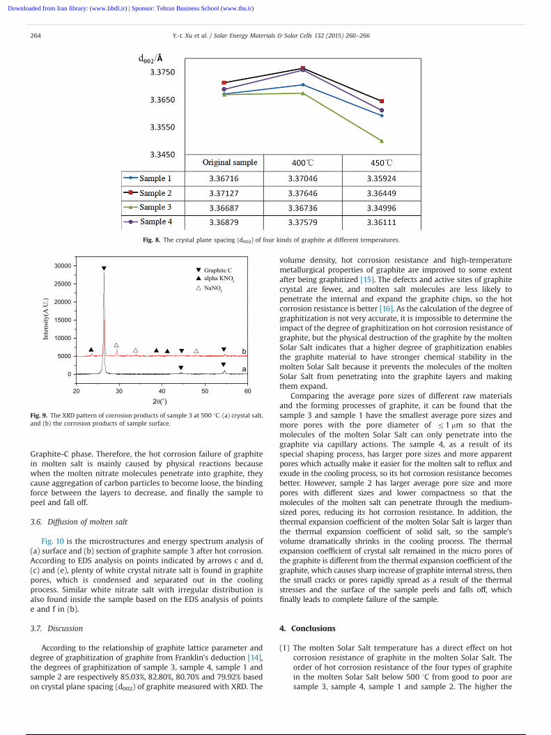
Graphite-C phase. Therefore, the hot corrosion failure of graphitein molten salt is mainly caused by physical reactions becausewhen the molten nitrate molecules penetrate into graphite, theycause aggregation of carbon particles to become loose, the bindingforce between the layers to decrease, and finally the sample topeel and fall off.
3.6. Diffusion of molten salt
Fig. 10 is the microstructures and energy spectrum analysis of(a) surface and (b) section of graphite sample 3 after hot corrosion.According to EDS analysis on points indicated by arrows c and d,(c) and (e), plenty of white crystal nitrate salt is found in graphitepores, which is condensed and separated out in the coolingprocess. Similar white nitrate salt with irregular distribution isalso found inside the sample based on the EDS analysis of pointse and f in (b).
3.7. Discussion
According to the relationship of graphite lattice parameter anddegree of graphitization of graphite from Franklin's deduction [14],the degrees of graphitization of sample 3, sample 4, sample 1 andsample 2 are respectively 85.03%, 82.80%, 80.70% and 79.92% basedon crystal plane spacing (d002) of graphite measured with XRD. The
volume density, hot corrosion resistance and high-temperaturemetallurgical properties of graphite are improved to some extentafter being graphitized [15]. The defects and active sites of graphitecrystal are fewer, and molten salt molecules are less likely topenetrate the internal and expand the graphite chips, so the hotcorrosion resistance is better [16]. As the calculation of the degree ofgraphitization is not very accurate, it is impossible to determine theimpact of the degree of graphitization on hot corrosion resistance ofgraphite, but the physical destruction of the graphite by the moltenSolar Salt indicates that a higher degree of graphitization enablesthe graphite material to have stronger chemical stability in themolten Solar Salt because it prevents the molecules of the moltenSolar Salt from penetrating into the graphite layers and makingthem expand.
Comparing the average pore sizes of different raw materialsand the forming processes of graphite, it can be found that thesample 3 and sample 1 have the smallest average pore sizes andmore pores with the pore diameter of r1 mm so that themolecules of the molten Solar Salt can only penetrate into thegraphite via capillary actions. The sample 4, as a result of itsspecial shaping process, has larger pore sizes and more apparentpores which actually make it easier for the molten salt to reflux andexude in the cooling process, so its hot corrosion resistance becomesbetter. However, sample 2 has larger average pore size and morepores with different sizes and lower compactness so that themolecules of the molten salt can penetrate through the medium-sized pores, reducing its hot corrosion resistance. In addition, thethermal expansion coefficient of the molten Solar Salt is larger thanthe thermal expansion coefficient of solid salt, so the sample'svolume dramatically shrinks in the cooling process. The thermalexpansion coefficient of crystal salt remained in the micro pores ofthe graphite is different from the thermal expansion coefficient of thegraphite, which causes sharp increase of graphite internal stress, thenthe small cracks or pores rapidly spread as a result of the thermalstresses and the surface of the sample peels and falls off, whichfinally leads to complete failure of the sample.
4. Conclusions
(1) The molten Solar Salt temperature has a direct effect on hotcorrosion resistance of graphite in the molten Solar Salt. Theorder of hot corrosion resistance of the four types of graphitein the molten Solar Salt below 500 1C from good to poor aresample 3, sample 4, sample 1 and sample 2. The higher the
Fig. 8. The crystal plane spacing (d002) of four kinds of graphite at different temperatures.
20 30 40 50 60
0
5000
10000
15000
20000
25000
30000
Inte
nsity
(A.U
.)
2θ( )
b
a
Graphite Calpha KNO3
NaNO3
Fig. 9. The XRD pattern of corrosion products of sample 3 at 500 1C. (a) crystal salt,and (b) the corrosion products of sample surface.
Y.-t. Xu et al. / Solar Energy Materials & Solar Cells 132 (2015) 260–266264
Downloaded from Iran library: (www.libdl.ir) | Sponsor: Tehran Business School (www.tbs.ir)
5 / 7

degree of graphitization, the better is the hot corrosion failureresistance in molten salt. The hot corrosion resistance times ofthe four types of graphite are very short in the molten SolarSalt above 500 1C.
(2) The sample 3 and sample 4 can be used as the material to storeand transport the heat storage medium in solar thermal powergeneration at around 450 1C.
(3) The corrosion failure of graphite in the molten Solar Saltis mainly caused by physical reaction because molten saltmolecules penetrate into the graphite and cause its volume toexpand and then initiate cracks as its volume decreasesduring subsequent cooling. Therefore, there is no chemicalreaction or the generation of a new phase in the wholeprocess.
Fig. 10. The microstructure and energy spectrum analysis of sample 3. (a) Microstructure of point A, (b) microstructure of point B, (c) the elements of point c, (d) theelements of point d, (e) the elements of point e, and (f) the elements of point f.
Y.-t. Xu et al. / Solar Energy Materials & Solar Cells 132 (2015) 260–266 265
Downloaded from Iran library: (www.libdl.ir) | Sponsor: Tehran Business School (www.tbs.ir)
6 / 7

References
[1] Xiang-yang Shen, Qiang Peng, Jian-ping Yang, Yu-liang Wen, Current status ofheat transfer fluid researched for concentrating solar power, GuangdongChem. Ind. 8 (2011) 83–85.
[2] W.E. Kirst, W.M. Nagle, J.B. Castner, A new heat transfer medium for hightemperatures, Trans. Am. Inst. Chem. Eng. 36 (1940) 371–376.
[3] R.W. Bradshaw, D.E. Meeker, High-temperature stability of ternary nitrate moltensalts for solar thermal energy systems, Sol. Energy Mater. 1 (1990) 51–60.
[4] M. Kamimoto, T. Tanaka, Investigation of nitrate salts for solar latent heatstorage, Sol. Energy 6 (1980) 581–587.
[5] R. Ferri, A.C.D. Mazzei, Molten salt mixture properties in RELAP5 code forthermodynamic solar applications, Int. J. Therm. Sci. 12 (2008) 1676–1687.
[6] D. Kearney, B. Kelly, U. Herrmann, Engineering aspects of a molten salt heattransfer fluid in a trough solar field, Energy 5–6 (2004) 861–870.
[7] Q. Peng, J. Ding, X. Wei, The preparation and properties of multi-componentmolten salts, Appl. Energy 9 (2010) 2812–2817.
[8] Qiang Peng, Xiao-lan Wei, High temperature thermal stability of molten saltsmaterials, Int. J. Energy Res. 12 (2008) 1164–1174.
[9] Yu-liang Wen, Transport Characteristic and its Enhancement Mechanism forTransverse Ridged Tubes with Molten Salts Materials in Receiver (Doctoral
dissertation), South China University of Technology, Central South UniversityPress, HuNan, 2010.
[10] Yu-ting Wu, Jian-kun Zhu, Li-Na Zhang, Chong-fang Ma, Preparation andexperimental study on high temperature molten salt, J. Beijing Univ. Technol. 1(2007) 62–67.
[11] Xiang-yang Shen, Jing Ding, Qiang Peng, Jian-ping Yang, Application of hightemperature molten salt to solar thermal power, Guangdong Chem. Ind. 11(2007) 49–52.
[12] James E. Pacheco, Demonstration of solar generated electricity on demand: thesolar two project, J. Sol. Energy Eng. 5 (2001) 124–128.
[13] Hai-peng Qiu, Quan-gui Guo, Yong-zhong Song, Geng-tai Zhai, Jin-ren Song,Lang Liu, Study the Relationship between conductivity and microcrystallineparameters of bulk graphite, New Carbon Mater. 1 (2002) 36–40.
[14] Fu-qin Zhang, Qi-ming Huang, Qian-ming Gong, Bo-yun Huang, Teng-fei Chen,Hui-juan Xu, Dong-ying Ji, Effect of graphitization degree on the mechanicalproperties of C/C composites, J. Cent. South Univ. Technol. 3 (2001) 289–293.
[15] Si-xin Huang, Yong-kang He, Li-qiao Ma, Production, applications and domesticmarket analysis for isostatically pressed graphites, Carbon Tech. 5 (2010) 32–37.
[16] Xiao-jun Hu, Xiang-xin Xue, Pei-ning Duan, Xiao-yu Huang, Guo-zhi Zhou,Effect of graphitization degree on properties of self baking carbon block,Chin. J. Nonferr. Met. 8 (1998) 67–72.
Y.-t. Xu et al. / Solar Energy Materials & Solar Cells 132 (2015) 260–266266
Downloaded from Iran library: (www.libdl.ir) | Sponsor: Tehran Business School (www.tbs.ir)
Powered by TCPDF (www.tcpdf.org)
7 / 7