Hospital Lobby Assistant Robot Built on a Segway Robotic ... · Hospital Lobby Assistant Robot...
101
Hospital Lobby Assistant Robot Built on a Segway Robotic Mobility Platform A Major Qualifying Project Submitted to the Faculty of Worcester Polytechnic Institute In partial fulfillment of the requirements for the Degree in Bachelor of Science In Robotics Engineering, Mechanical Engineering, and Computer Science By _________________________ Joe Fainer (RBE) _________________________ Tom Farro (RBE) _________________________ Jacob Hackett (RBE/CS) _________________________ Erin Leger (RBE) _________________________ Emily Yu (ME) Project Advisors: _________________________ Professor Gregory Fischer _________________________ Professor Candace Sidner Date: 04/26/2017
Transcript of Hospital Lobby Assistant Robot Built on a Segway Robotic ... · Hospital Lobby Assistant Robot...

Hospital Lobby Assistant Robot Built on a Segway Robotic Mobility Platform
A Major Qualifying Project Submitted to the Faculty of
Worcester Polytechnic Institute In partial fulfillment of the requirements for the
Degree in Bachelor of Science In
Robotics Engineering, Mechanical Engineering, and Computer Science By
_________________________
Joe Fainer (RBE)
_________________________ Tom Farro (RBE)
_________________________ Jacob Hackett (RBE/CS)
_________________________ Erin Leger (RBE)
_________________________ Emily Yu (ME)
Project Advisors:
_________________________
Professor Gregory Fischer
_________________________ Professor Candace Sidner
Date: 04/26/2017
1 Abstract 5
2 Executive Summary 6
3 Introduction 9
4 Literature Review 13
5 Project Strategy 16 5.1 Initial Problem Statement 16 5.2 Objectives and Constraints 16
5.2.1 Mandatory Goals 16 5.2.1.1 Teleoperation 16 5.2.1.2 Safety 17 5.2.1.3 Navigation and Mapping 17 5.2.1.4 Arm 17 5.2.1.5 Simple Touchscreen Interface 18
5.2.2 Reasonable Goals 18 5.2.2.1 Obstacle Avoidance 18 5.2.2.2 Improved End User Interface 18 5.2.2.3 Patient Information Database 19 5.2.2.4 Able to Open Door or Curtain 19 5.2.2.5 Aesthetic Chassis Design 19
5.2.3 Reach Goals 20 5.2.3.1 Facial Recognition and Identification 20 5.2.3.2 Able to Help Fill Out Patient Paperwork 20 5.2.3.3 Intelligently Plan Patient Room Assignments 20 5.2.3.4 Smarter Obstacle Avoidance 21 5.2.3.5 Voice Recognition and Natural Language Processing 21
5.2.4 Constraints 21 5.3 Project Approach 22
6 Design Process 22 6.1 Needs Analysis 22
6.1.1 Segway Robot 22 6.1.1.1 Control Computer 23
6.1.2 System Architecture 23 6.1.3 End User Interface 26 6.1.4 Arm 26
6.1.4.1 Arm Control 27 6.2 Prototyping/Modeling 28
6.2.1 Segway Robot 28
1

6.2.2 System Architecture 29 6.2.3 End User Interface 30 6.2.4 Arm 35
6.3 Alternative Designs 37 6.3.1 Segway RMP 37 6.3.2 System Architecture 37 6.3.3 End User Interface 38 6.3.4 Arm 39
6.4 Final Design Selection 44 6.4.1 Segway Robot 44
6.4.1.1 Control Computer 46 6.4.2 System Architecture 47 6.4.3 End User Interface 47 6.4.4 Arm 48 6.4.5 Arm Control 54
7 Final Design Verifications 57 7.1 Segway Robot 57
7.1.1 Batteries 57 7.1.2 Electronics 58 7.1.3 Driving 59
7.2 System Architecture 59 7.2.1 Communications Node 61 7.2.2 Eyes Controller 62 7.2.3 Directions Node 62 7.2.4 Open Door Controller 62 7.2.5 Operate Elevator Controller 62 7.2.6 Pan Tilt Node 63 7.2.7 Driving Controller 63 7.2.8 Driving Node 63 7.2.9 Arm Controller 63 7.2.10 Arm Driving Node 64 7.2.11 Touchscreen Interface 64 7.2.12 Node Server 64 7.2.13 Patient Database 64 7.2.14 Eyes Interface 65
7.3 End User Interface 65 7.4 Arm 66
7.4.1 Machining the Links 66
2

7.4.2 First Joint Gearbox 67 7.4.3 Second Link Belt System and Gearbox 68 7.4.4 Center Mast and Slider Mechanism 69 7.4.5 Potentiometer and Mounts 70
8 Final Design Validation 72 8.1 Mandatory Goals 72
8.1.1 Teleoperation 72 8.1.2 Safety 72 8.1.3 Navigation and Mapping 73 8.1.4 Arm 73 8.1.5 Simple Touchscreen Interface 73
8.2 Reasonable Goals 74 8.2.1 Obstacle Avoidance 74 8.2.2 Improved End User Interface 74 8.2.3 Patient Information Database 74 8.2.4 Able to Open Door or Curtain 75 8.2.5 Aesthetic Chassis Design 75
8.3 Reach Goals 75 8.3.1 Facial Recognition and Identification 75 8.3.2 Able to Help Fill Out Patient Paperwork 75 8.3.3 Intelligently Plan Patient Room Assignments 76 8.3.4 Smarter Obstacle Avoidance 76 8.3.5 Voice Recognition and Natural Language Processing 76
9 Discussion 76 9.1 Segway Robot 76 9.2 System Architecture 77 9.3 End User Interface 78 9.4 Arm 78 9.5 Challenges 79
9.5.1 Segway RMP 79 9.5.2 Software 82 9.5.3 Hardware 83
10 Conclusions and Recommendations 84 10.1 Segway RMP 84 10.2 Software 85 10.3 Hardware 86
11 References 88
3

12 Appendices 89 12.1 Appendix A: Arm Calculations 89 12.2 Appendix B: Electrical System 92 12.3 Appendix C: Resources and Components 96 12.4 Appendix D: Authorship and Contributions 99
4
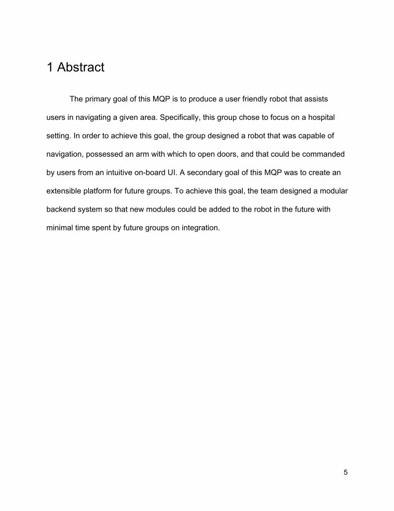
1 Abstract
The primary goal of this MQP is to produce a user friendly robot that assists
users in navigating a given area. Specifically, this group chose to focus on a hospital
setting. In order to achieve this goal, the group designed a robot that was capable of
navigation, possessed an arm with which to open doors, and that could be commanded
by users from an intuitive on-board UI. A secondary goal of this MQP was to create an
extensible platform for future groups. To achieve this goal, the team designed a modular
backend system so that new modules could be added to the robot in the future with
minimal time spent by future groups on integration.
5

2 Executive Summary
This report details a Major Qualifying Project done during the 2016-2017 school
year that focused on improving the state of a Segway Robotic Mobility Platform (RMP)
that was in possession of the AIM Lab. The main goal of the project was to create a
robotic platform that could improve visitor experience while in doctor offices or hospitals.
The platform had to be user friendly and able to navigate its environment. A secondary
goal of the project was to bring the RMP to a state where it was extensible by future
groups. This paper looks at the design process and implementation while assessing the
results of the project. Below is a picture of the final product of the project.
Figure 2A: The final product for this project: A Segway RMP equipped with a touchscreen interface, planar arm, user interface, and new electronics
6

An arm is designed from bottom up based on the goals of opening doors by
turning lever handles and pressing elevator buttons. It consists of the main body of the
arm, which is able to follow the path of door openings, and the end effector that’s able to
grasp, rotate and pull the door handles to complete the initial step of unlatching.
Although the end effector is not currently on the robot, it is ready to be added so future
teams can move on to manipulation. Mathematical analysis such as Jacobian matrices,
forward kinematics, inverse kinematics was utilized to find out the required torque all
motors need, as well as relating them to positioning. The frames of the arm are
machined and most attachment parts of the arm are 3D printed.
In terms of software, a new backend architecture was devised and implemented,
alongside a new User Interface. The backend follows a Single-Responsibility-Principle
pattern so as to be easily accessible and extensible by future groups. The User
Interface is run in a web browser on the onboard computer, and communicates with the
backend over WebSocket using JSON messages. Additionally, a survey was conducted
to inform the design direction of the User Interface.
More details can be found in these chapters. In Chapter 3, the team introduces
the project in a succinct manner. Chapter 4 discusses previous work in this area such
as the Pepper robot or other human robot interactions. Chapter 5 details this project’s
goals and approach. Chapter 6 looks at the needs analysis for each category of the
project while also discussing prototypes and models. The team details final design
choices in Chapter 6 as well. Chapter 7 shows the results of implementing the final
designs. Chapter 8 ties in the results with the original goals of the project in an effort to
7

assess the success of the project. In Chapters 9 and 10, the team discusses the
different parts of the project and makes recommendations for future groups.
8

3 Introduction
Figure 3A: A render of the final robot
This project focused on improving the existing Segway based robot by updating
software, firmware, and hardware. The project organized the software architecture,
upgrading onboard computing, and added a redesigned arm to the platform. The overall
goal of the project was to create a more reliable and capable platform to be used in
future projects for a number of different applications.
The Segway Robotic Mobile Platform (RMP) was used in previous projects at
WPI. The first Major Qualifying Project (MQP) team set out to create an outdoor tour
guide robot which was intended to give short tours of the main campus while explaining
the history and use of a few key locations.
9

The result of the first project was a robot equipped with custom stereo-vision,
GPS, an accelerometer, and an array of ultrasonic sensors. These ultrasonic sensors
were intended to work together to localize the robot based on an existing map. The
team accomplished XBox 360 controller integration for manual control, stereovision,
limited obstacle avoidance, limited autonomous navigation, and push button controlled
dialogue. The team did not accomplish fully autonomous navigation and GPS reliability.
( LeBlanc, Patel & Rashid, 2012 ) The second MQP team focused on indoor navigation and replaced all of the
sensors. They tried to tailor the robot to a known indoor environment. They added a
Kinect camera at the top of the mast to recognize the shapes of elevator buttons, door
knobs, and numbers. They also replaced the stereo-vision with a LIDAR unit. Instead of
using GPS for localization on a large scale, they uploaded maps of individual floors of a
building allowing the robot to reliably locate itself using only LIDAR. The second team
achieved its goal of autonomous navigation among rooms in the same building but
failed to successfully incorporate the arm. ( Fischer & LeBlanc, 2012 ) In this iteration of the project, the team built a foundation for this robotic platform
so that the system can easily be improved upon for years to come. The main objective
is to create a more robust and permanent solution for interaction and mobility which can
be applied to many different situations and locations and then to further develop the
platform for a medical setting as an intake and guide robot for busy emergency room
and/or doctors’ offices. The robot should be able to check a patient into the office, save
10

patient information, and assign the patient to a room, then guide them to that room. In
order to achieve this, the team prioritized the goals listed below.
The goals of this project can be categorized into three sections:
mandatory, reasonable, and reach. In order to consider this project a success, the robot
must satisfy six mandatory constraints as follows:
● The robot must be able to drive through tethered teleoperation.
● The robot must be able to navigate autonomously through a known map
● The robot must have a safer chassis design as to encourage use in high traffic
areas such as hospitals.
● The robot must be able to plan navigation paths on given maps. It must also be
able to update these maps as it travels.
● The robot requires a functioning arm and must be able to use an elevator.
● Finally, the robot must have a simple touchscreen UI that communicates with the
rest of the system.
There are also five reasonable goals that are equally important for the project,
but have lower priorities than the mandatory goals, which are as follows:
● The robot should be able to perform obstacle avoidance so no unnecessary
injuries occur to people moving in the vicinity of the robot during operation..
● Investigate adding HRI Interface to improve the user experiences for the patients.
● Build a patient information database to store the information that is being
entered, and therefore, shorten the patients check in time on future visits.
● Improve the motion of the arm in order to open doors, pull curtains and gesture.
11

● Last, but not least, the design division of the team would like to perfect the
exterior look of the robot by making a more aesthetic and appealing chassis.
As for reach goals, we have a number of quality-of-life improvements on previous
goals that would enhance the utility of the robot a bit more. Reach goals are things we
would like to do but we don’t consider to be necessarily within the scope of an MQP.
These goals are as follows:
● Implement facial recognition and identification
● Create a system that assists patients in filling out paperwork
● Help staff plan room assignments for incoming patients
● Perform smarter obstacle avoidance by planning new paths around obstacles
● Use natural language processing and voice recognition to parse user commands
Over the course of this project, the team was able to accomplish several of these
goals including most of the mandatory goals and some of the reasonable goals. The
rest of this paper will discuss the project strategy, implementation, and results of this
work.
12

4 Literature Review
In research conducted by the Computer Science Department at Stanford
University, algorithms were explored to help robot manipulation open doors with many
variables. It discusses using 2D cameras to help establish key characteristics like
location of door handle, kind of doorknob, and axis of rotation required to open door.
This study provides knowledge of all the conditions that are necessary when planning
and designing a mechanism to open doors, as well as an approach to the problem.
( Klingbeil, Saxena & Ng, 2010 ) The same team at the University of Stanford also applied their algorithms in an
attempt to further advance mobile robot navigation. Like door, elevators have many
factors that, without previous knowledge, make robot manipulation difficult and limited to
single floors. Elevator panels vary in terms of button size, button orientation, and button
location. The team used a combination of cameras to help their algorithm detect those
button variables. Like the previous study, this one provides the knowledge of all
conditions necessary in operating an elevator, as well as give an idea to approach the
problem. ( Klingbeil, Carpenter Russakovsky & Ng, 2010 ) The University of Pennsylvania performed research on robots opening doors
(both push and pull) without collision of objects in the workspace. Most mobile platform
robots do not have robot arm manipulation that can open a door successfully without
moving the base. Opening a door requires a combination of robotic arm manipulation
and base navigation. This study presents a problem the team will have to deal with
13

designing the arm and when planning door operations. ( Chitta, Cohen & Likachev,
2010 ) Pepper, a robot created by Softbank, is being deployed inside Belgian hospitals
to help greet and intake visitors as they arrive. Pepper currently is designed to receive a
card from an incoming patient, identify corresponding information such as room
assignment or patient information, and direct the patient appropriately through the use
of a video as guidance. Its next phase will be personal guidance to rooms. Pepper
uses a built in screen to help communicate as well as give user interface when
applicable. Pepper offers real world results of a project the team is very closely
following. ( Sayer, 2016 ) The quest to make robots not only user friendly but user familiar has been going
on for years. Some people approach by adapting a specifically functional robot to a
social environment, while others start by studying what makes a robot relatable. Ryan
Wistort, previously of the MIT Media Lab, focused on discovering what would draw
someone to a robot. Heavily influenced by a classic book of design used by Disney
animators called “The Illusion of Life,” he created a number of caricature robots
including Tofu and Miso which both resembled fluffy baby penguins and were equipped
with animated OLED display eyes. ( Wistort, 2010 ) A major problem many teams run into when attempting to implement an
interactive robot into the workforce is how to gauge people’s response to not only the
personality of the robot but to the decisions it makes or suggestions it offers. A group of
students and researchers attempted to solve exactly that problem by having nurses
14

filling multiple roles as well as doctors in a working labor and delivery ward. They
studied the responses to various actions by the test devices in controlled situations in
order to learn ways in which they can make their robots more helpful rather than
cumbersome. This particular study is especially influential in our own work because it
deals directly with robots intended to take some pressure off of nurses in the
coordination of patient care and general office organization. ( Gombolay et al, 2016 )
15

5 Project Strategy
5.1 Initial Problem Statement
This team was asked to design and start developing a system that could be used
in a medical environment as a robotic secretary. The design of the project was heavily
influenced by the fact that this project would be extended in future years.
5.2 Objectives and Constraints
This section details the goals of this project. The goals are organized into three
categories based on priorities. Mandatory goals describe the goals that must be present
in this project to consider it a success. Reasonable goals are goals that are potentially
obtainable. Reach goals are ambitious goals that are of the lowest priority but would
make nice additions to the project.
5.2.1 Mandatory Goals
5.2.1.1 Teleoperation
The first and possibly simplest goal the team needed to achieve is to prepare the
Segway Robotics Mobility Platform for teleoperation. Each RMP is sold with a collection
of software which allows limited control of the base. Therefore, to achieve teleoperation,
the base simply needed to receive externally-controlled input that matches what it would
16

expect to get from the aforementioned software library, and act on those inputs as
expected.
5.2.1.2 Safety
One of the primary goals of this project is to increase the safety of the RMP and
the arm. There are several different kinds of safety features needed to accomplish this
goal. First, it is important that the physical structure of the robot is devoid of sharp
protrusions and open wires. Second, the robot must not drive into structures or people
while operating. Third, the robot must have a reliable system for emergency stop. This
means that an easily accessible button is apparent and available to stop operation of
the RMP and arm without shutting down the onboard computer.
5.2.1.3 Navigation and Mapping
The second mandatory goal for this project was autonomous navigation. The
robot must be able to calculate a path to a point on a known map from its current
position and it must be able to drive there. In ROS, many tools which achieve this goal
exist for a variety of platforms. As such, one needs to be used and adapted for the
Segway RMP if no such tool already exists.
5.2.1.4 Arm
The purpose of the arm is to provide the segway robot expanded reach to other
parts of the map. The arm is expected to be able to assist the robot in opening doors.
This operation aids the goal of being able to lead patients to their appropriate room
17

within the hospital/doctor’s office. Another purpose of the arm is operation of an
elevator to increase the mobility even further. The overall design of the arm should be
be able to perform or assist in both actions.
5.2.1.5 Simple Touchscreen Interface
The purpose of the UI is to provide a simple, intuitive experience for the user to
communicate with the robot. The UI is expected to have workflows for checking in a
patient, giving directions to rooms or bathrooms, finding someone’s loved one,
contacting staff, and alerting staff of an emergency. The UI will interface directly with
ROS and allow the user to select commands to give the robot.
5.2.2 Reasonable Goals
5.2.2.1 Obstacle Avoidance
This goal is part of our safety functionality. The robot should not hit structures or
people while driving around an environment. In order to accomplish this goal, the robot
should be able to stop when an obstacle is in its path and wait for it to leave its path to
continue driving. This is really only a suitable solution if the obstacle is a mobile person
or object. A better solution, that is part of our reach goals for this project, is to plan a
new path when something blocks the current path.
5.2.2.2 Improved End User Interface
It is important to continue to iterate on the design of the end user interface,
especially after receiving feedback from users. This goal describes the effort to adapt
18

the UI according to feedback so it is easier to use. It also includes adapting the user
interface so it is more aesthetic, following common design practices such as material
design.
5.2.2.3 Patient Information Database
Adding a patient database to our system adds several possible improvements. It
opens opportunities to allow users to register for services at the doctor’s office or
hospital. Adding a database allows the team to effectively organize data and expand the
functionality of the system.
5.2.2.4 Able to Open Door or Curtain
In order for the robot to effectively navigate a hospital or office setting, it must be
able to open doors. Integrating door opening capabilities will increase the mobility and
the application of the robot. For the scope of this project, the arm functionality is likely
be tuned to a singular door due to the difficulty opening doors presents in robotics.
5.2.2.5 Aesthetic Chassis Design
In an effort to make the robot approachable, the team would like to change the
chassis of the robot to be more aesthetic while not limiting functionality. A robot like
Pepper is much easier to approach as an end user than a Segway RMP in its default
state.
19
5.2.3 Reach Goals
5.2.3.1 Facial Recognition and Identification
In order to improve the user experience when using the robot, it would be nice to
have facial recognition. Being able to move the robot so it is facing, or looking at, the
current user would make it a much more enjoyable experience. Facial identification
would further improve the user experience because the robot would be able to know
who was operating it and cater the experience for that person.
5.2.3.2 Able to Help Fill Out Patient Paperwork
One of the least enjoyable parts of going to the doctor’s office is filling out
paperwork. It would be easier to fill out paperwork with some help from word prediction
and other well designed tools that help efficiently and effectively fill out forms on the
web. This information could easily be part of the patient information database.
5.2.3.3 Intelligently Plan Patient Room Assignments
In order to increase the efficiency at which patients leave and enter the doctor’s
office, the robot could plan where patients will go and help them go to that location. This
may be faster than having a secretary or assistant plan the room assignments
themselves.
20

5.2.3.4 Smarter Obstacle Avoidance
This smarter obstacle avoidance was mentioned earlier while discussing basic
obstacle avoidance. This goal describes the functionality for planning a new path when
an obstacle enters the current path of the robot. This would prevent the robot from
hitting obstacles such as objects and people but would require SLAM algorithms.
5.2.3.5 Voice Recognition and Natural Language Processing
Another feature that could potentially increase the user experience of the robot is
voice recognition and natural language processing. It is often more intuitive to use voice
commands than clicking on a screen and typing commands. This goal requires near
field voice recognition and natural language processing.
5.2.4 Constraints
The most surface-level constraint to this project was the budget. Initially, the
project was granted $1000 for expenses, granting each student $200. However, shortly
into the duration of the project, the team was granted an additional $50 per member,
bringing the total project budget to $1250. Additional constraints include the weight, size
and capacity of the Segway RMP base; the additions made to the RMP needed to be
light enough to not over-encumber the driving motors. Additionally, we needed to
approach the problem of door-opening in such a way so as to not apply more torque on
the RMP than it was capable of overcoming.
21

5.3 Project Approach
Since this project has many different facets and addresses each of the three
main disciplines of robotics, the team decided to split this project into four categories:
Segway RMP and electronics, user interface, system architecture, and the new arm.
The team started to approach the project by enumerating and analyzing the needs that
would have to be met in each of these categories, so as to achieve the outlined goals of
the project. In the coming chapters, this process will be detailed and tied in with the
goals to assess the results of the project.
6 Design Process
6.1 Needs Analysis
This section of the paper details the needs of each part of the process. It looks at
what the team must have in order to complete the project goals.
6.1.1 Segway Robot
In the interest of creating a modular and extensible platform, this year’s project
put a good deal of focus on upgrading and improving the physical system as a whole.
The existing platform had not been upgraded since 2013 and the computer, for the most
part, was original to the 2011 project. In order for the platform to execute the goals of
this project a new computer was necessary and it was a perfect opportunity to scale
22

down the control system to save space and weight. The RMP, on the other hand, was
not only out of date but had been sitting idle resulting in critical battery drain as well as
other issues. This also became an opportunity as Segway offered to fix and upgrade the
platform.
6.1.1.1 Control Computer
This version of the project required that the computer built for it be compact and
powerful; unfortunately, available pre-assembled compact systems are expensive and
do not offer the performance we needed. According to Stanley Innovation, who maintain
ROS packages for newer Segway Robotics products, a control computer should have at
minimum 8G RAM. We also knew we would want to use a solid state hard drive
because it would be jarred and shaken quite a lot while the robot is moving.
6.1.2 System Architecture
Because the team inherited the Segway RMP from a previous project team, and
the teams suspected that a future team would be inheriting the project from them,
flexibility of infrastructure was determined to be the the preeminent requirement for the
back-end system. The system would need to be able to accommodate new
functionalities and arbitrary implementations of these functionalities with minimal
refactoring on the part of future developers.
As evidenced by the architecture, the entire system design was driven by the
idea of modularity. Every piece of the system should work independently of one another
and be easily testable. This falls in line with the ROS philosophy and allows future
23

groups to expand or edit functionality easily. It is also easier for new programmers to
understand the system if nodes only have one purpose.
For the front end of the system, the team decided to use a web based interface.
There are a couple reasons for this. First, web is platform agnostic. This system can talk
to any website hosted on any server. Second, the team had a lot of prior experience in
web development and could easily implement even the most complicated of user
interfaces.
In addition to the front end web interface, the team created a Node.js server to
facilitate any requests that the user made that did not require the robot’s knowledge.
This was useful in querying the patient database or requesting assistance from a staff
member. Both of these tasks can be done without sending any commands to the robot
base so we decided to abstract out that behavior to a web server.
This server also provides several useful tools for developing the web side of the
project. The team was able to use a JavaScript templating library, called Handlebars.js
to make creating new webpages easy and quick. The server also made connecting to a
database seamless. The team connected to a Mongo database hosted on MongoLab
through a JavaScript library called Mongoose. This library also provided tools to define
table schema and default values.
For the back end of the system, the team decided to use ROS, primarily because
we had prior experience with it throughout the undergraduate curriculum. For
communication between the front and back ends of the system, the team utilized
websockets to send JSON messages back and forth between the JavaScript-based
24

front end and the Python-based system back end. Because JSON is essentially a
structured piece of plaintext, it makes for a reliable way to communicate data between
disparate programming languages and architectures.
In particular, JSON communication is used to emulate the state-machine
architecture that would be inherent in something like a dedicated Java application.
Because the UI is browser-based and functions asynchronously with respect to the
Python server, the two systems presented a potential risk of desynchronizing from one
another. However, by using JSON, we were able to require that the front end sends a
request to the back end when it needs to advance through pages. The back end could
then either approve the request and allow the browser to load a new page, or deny the
request and keep the browser where it was. In this way, we prevented instances where
the UI could navigate to a page that it should not be navigating towards for the current
step of operation, or to a page that would deliver information to the back end without
proper context. We essentially created a TCP-like networking protocol between the front
end and the back end of the robot.
Additionally, JSON messages are used to used to process user-given
commands. Because the front end pipes all communication to the the back end through
the single communication node, that node is, in turn, responsible for interpreting the
message and dispatching the command to one of its relevant child nodes. This
functionality is accomplished by building a robust callback function that examines the
incoming JSON to determine what type of command it is, and then delegates the
command and its associated information to the relevant child node.
25

6.1.3 End User Interface
The only thing that the project needed in order to implement an end user
interface was a touchscreen interface. The old touchscreen interface is an all-in-one
computer that complicated the integration of the systems. Buying a new touchscreen
interface streamlines the development process and simplifies communications between
different parts of the robot.
6.1.4 Arm
After conducting research on existing robots, the team decided the next step was
the preliminary considerations for the arm design. The arm was determined to need a
pulling motion towards the robot, as well as a slight translation up and down in order to
accomplish the tasks. The pulling motion towards the door is based on the human
mechanics of opening a door. When a person walks to the door, they reach out with
their hand/arm, grab the door, and pull it open towards them. While a human arm has
many degrees of freedom, a translational motion towards the robot can be derived from
the process. Due to time and budget restraints, the team wouldn’t be able to design and
build a arm similar to a human's arm that would make motion planning as exact as
desired. The relative speed of the arm does not have to be fast. In fact having a slower
controlled arm would keep the potential safety risk low if a malfunction ever occurred.
The arm would have to be strong enough to operate a spring loaded door.
Thus, for this project, the arm designs are under the assumption of opening
doors in a commercial setting with level shape handles that are about 42 inches above
26

the ground. To rotate the door handles, it requires F1=5 lb of force, with a distance of
4.5 inches from the center of rotation, the arm has to esert 22.5 lb.in of torque to turn
the handle in order to successfully unlatch the door. The team also measured the
amount of force it takes, which is 9 lb, to pull a typical spring-loaded door open. The
figure below is a sketch of the front view of a door handle with the interested variables
labeled.
Figure 6A: Sketch of door handle with variable labels
6.1.4.1 Arm Control
In order to control the arm we would need to be able to send joint commands to
an Arduino which would handle the control loop to run each of two brushed DC motors
and two servos. It required a ROS node which allows communication between the
Arduino and a python script running on the main computer which takes care of the
kinematics of the arm.
Routing power to the motors was also an involved process since both motors
needed 12 volts and could each draw over 15 amps. We needed to design a system
which would keep the motor drivers from overheating and allow power to be cut off
quickly.
27

6.2 Prototyping/Modeling
6.2.1 Segway Robot
Several parts involved in the electronics and arm control were made from scratch
using both laser cutting and 3D printing. The acrylic panels for mounting hardware and
the potentiometer brackets were both modeled in Solidworks.
In order to determine how to lay out the panels finished electronic components
were laid out on a table in a way that they could be reached and used easily and the
locations of all the mounting points were mapped.
Figure 6B: Rendering of potentiometer mount
28

Figure 6C: Rendering of acrylic panels for mounting electronics
Circuits involved in the arm control system were first constructed on breadboards
in order to verify that all connections worked as expected. It was important to decide
ahead of time which operation modes we were to use with each of the DC motor drivers
as each one used different pins in different ways. We chose to use the drive/coast
method for the larger motor which requires the use of both PWM pins, we also decided
to use current sensing on both motor drivers.
6.2.2 System Architecture
Because the primary driving and navigation functionality of the robot was similar
to a turtlebot, the team turned towards its previous experience with turtlebots when
deciding how to build the robot system. In prior work, we had used ROS to connect all
the turtlebot functions together. ROS inherently lends itself to a distributed type of
29

system, and so the system architecture connecting the User Interface to the
functionality was also constructed in a distributed manner.
When deciding on what type of protocol to use to communicate between the User
Interface and the system, the team was faced with a couple of options. One option was
to do what the previous group had done: have an entire separate computer running the
touchscreen, which would connect over serial to the main computer. This approach
seemed convoluted and needlessly complicated. The idea of using a browser-based UI
and connection to a backend system via WebSocket was proposed by a team member
who had used a similar implementation during a video game development project.
Because of its ease of implementation and because of its flexibility, we opted to follow
this approach.
6.2.3 End User Interface
The team started the user interface design period by sketching out several
possible interfaces These interfaces were designed to be simple and intuitive. As such,
the primary design considerations taken were to create large, single-color buttons and
to put clear iconography on them. The team hoped that these considerations would help
anyone, regardless of their English-language comprehension skills, to use the interface.
Initial prototype designs for the User Interface also featured a pair of eyes, similar to
Baxter and other social robots. These eyes were planned to be used with user tracking,
should the project reached a point where that reach goal would become achievable.
30

Figure 6D: Preliminary UI designs featuring eyes and large buttons
From initial sketches, the team develop several prototypes in HTML5 and CSS3.
These tools allowed for very fast iteration and prototyping. Below are several designs
that the team developed during this process.
Figure 6E: Initial designs had the eyes and interactions on the same display
31

Figure 6F: Later iterations removed the eyes for a streamlined interactions display
Figure 6G: The team further simplified the interactions display for clarity
32

Once the team settled on the above design for the interactions display, it was
necessary to assess how clear the UI was for its intended audience. The team
conducted a user survey on 48 individuals. The survey gave a brief overview of the
robot’s design and functionality, and then presented three types of questions in three
respective sections. The first section was a free-response, which presented an image of
a UI button, asking participants to write what the expected might happen if they were to
select the button. The second section was a numeric rating system, where we provided
an image of a UI button along with a description of what it would actually do, and asked
participants to rank how clear they thought that was in retrospect. The third and final
section asked participants to fill out some demographic information, such as age, their
primary language, and level of education.
Figure 6H: An example of the first type of question
33

Figure 6I: An example of the second type of question
Figure 6J: An example of the third type of question
It was found that the vast majority of participants (>85%) found that the buttons
had clear functionality and that the function mimicked their expectations (Figure 6J).
However, these results are likely to be heavily biased, as a similar percentage of
participants also reported that English was their native language. As such, the interface
may not be as clear as it could be to non-English speakers, but data for that
demographic was not able to be generated. Still, these results helped influence the
team towards designing the final interface.
34

Figure 6K: Example Survey Results
6.2.4 Arm
In order for the team to conceptually prove the concept of the arm design, the
team created a inexpensive prototype. The prototype consisted of laser cut wood pieces
that were cut to scale of what the arm would actually be. (Figure 6K) The links were
connected via a vex shaft to give enough rigidity as the prototype needed. The team
then walked through the motion phases of the arm providing evidence that with the
design in hand the task of opening a door is possible.
35
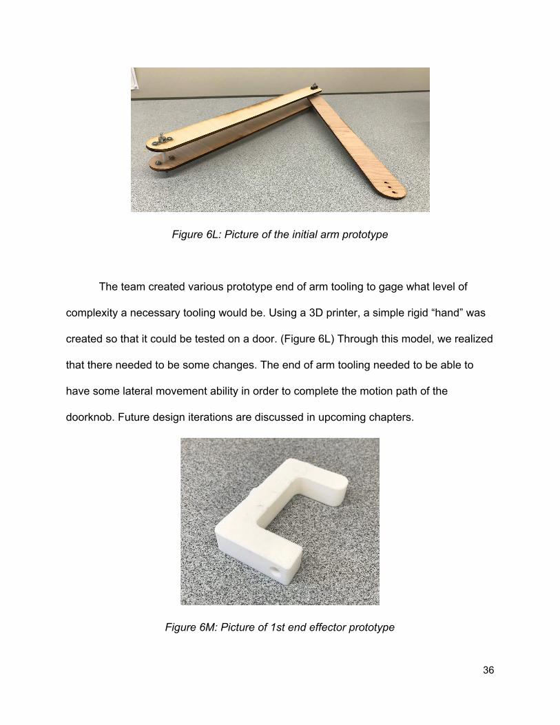
Figure 6L: Picture of the initial arm prototype
The team created various prototype end of arm tooling to gage what level of
complexity a necessary tooling would be. Using a 3D printer, a simple rigid “hand” was
created so that it could be tested on a door. (Figure 6L) Through this model, we realized
that there needed to be some changes. The end of arm tooling needed to be able to
have some lateral movement ability in order to complete the motion path of the
doorknob. Future design iterations are discussed in upcoming chapters.
Figure 6M: Picture of 1st end effector prototype
36

6.3 Alternative Designs
6.3.1 Segway RMP
When our project began the Segway RMP had a much larger top plate set on
solid side panels. The side panels were made of the same heavy material as the top
plate and had several threaded holes like the top plate. Because of this the original plan
to mount the computer and electrical components was to build horizontal shelves like
the previous groups, even to reinstall the shelves which we had removed for cleaning.
Originally the plan for operating the arm involved directly providing power to the
motors and relying on the main emergency stop button if the arm needed to be shut
down. This would have been easier than what was settled on and would have worked.
However, even though the control computer is not powered off the base batteries the
Arduino was. Thus cutting power to it would mean restarting the control program and
re-establishing a serial connection.
6.3.2 System Architecture
The primary alternative to the modular, Single-Responsibility-Principle pattern
would be to tightly couple our code, which is something of an antipattern. While putting
everything in one place works for small systems, once systems grow, they rapidly
become impossible to untangle. As a result, extracting functionalities from systems built
in this way becomes a tedious task, and these systems are severely limited in terms of
37

flexibility. Because this project was intended to be handed off to future groups and
expanded upon, a tightly-coupled system is not an ideal alternative.
6.3.3 End User Interface
Since the team designed the end user interface in an iterative manner, there
were many different versions of the interface but each version improved on the prior in
some way. The team prioritized clarity and aesthetics when designing the interface and
tried to improve on both of those with each iteration. These different designs can be
seen in the Prototyping/Modeling section as part of the methodology behind designing
the interface.
An obvious alternative to our browser-based approach would be to create a
standalone application using Java or Python. While these methods have merit, they
were less suited for our needs. Because we already had a backend Python server, we
did not need the User Interface to do any computational work, and instead just needed it
to provide a good User Experience. The primary advantage of standalone applications
is that they can also be responsible for being both the frontend and the backend
simultaneously, but because of that are more tightly coupled. As a result, these
implementations would become harder to add new functionalities for, and would take
more time to prototype, because they would require compiling on each small adjustment
to the UI layout. The browser-based UI, on the other hand, can be modified rapidly
through CSS, and allows for easy extension of the backend with minimal changes, as
there is minimal coupling.
38

6.3.4 Arm
The team collaborated as many ideas as they thought applied to the scope of the
project, while not considering ideas that would over complicate the imagined motion
path. The team came up with the following 8 designs.
Figure 6N: Design 1 and 2 of the arm were very similar
The first design that the team came up with was a basic 2 DOF planar arm that
consisted of 2 revolute joints. It was modeled after the human arm with the first joint,
the one closest to the base, being the shoulder. The second joint therefore resembling
the elbow, and the end of the arm being the beginning of the hand. Design 1 and 2
differ in the way they are oriented with respect to the wheelbase. Design 1’s orientation
has the arm moving as if the arm was parallel to the wheelbase, while the other
orientation has it perpendicular to the wheelbase. Design 1 has the benefits of being
able to have motion up and down as well as in and out, but therefore has no capable
motion left and right. Design 2 trades motion capabilities, allowing motion left and right
39

as well as in and out, but doesn’t allow motion up and down. Outside of opening a
door, Design 2 holds the potential for more functions.
Figure 6O: Design 3 of the arm
Design 3 was an idea that aimed to create the simplest possible arm. The arm is
1 DOF with linear motion. This design keeps kinematics simple and allows for motion
inward and outward from the robot. This motion allows the necessary pulling to open a
door, but doesn’t allow any leeway for other functions other than opening a door. Even
opening a door would likely require a complex end of arm tooling to create more degree
of freedom capabilities. This design did allow sturdiness and strength.
Figure 6P: Design 4 of the arm
40

The fourth design the team created took the model of design 1, but tried to make
it slightly different. The design is a 2 DOF arm with one joint being planar and the other
being rotation. This design allows for motion up and down as well as inward and
outward rotation, but is lacking the ability to move left and right. This design has simpler
calculations compared to Design 1, but lacks diversity in regard to other applicable
functions and adaptivity.
Figure 6Q: Design 5 of the arm
Design 5 plays off the idea of Design 4, but creates the 2 DOF system another
way. This design is also similar in motion to Design 1, but allows the arm to be placed
at the center of the robot. This design also allows for variation in door handle heights
due to its ability to translate up and down. The cons of this design, like Design 1, are
that the motion of the arm is purely up and down, making side to side motion, something
involved in opening a door, very difficult.
41

Figure 6R: Design 6 of the arm
Design 6 formulates from a gantry system. This idea would be a 3 DOF system
with the ability to translate up and down, left and right, as well as into and out of the
robot. Benefits of this design include easy, pinpoint location of the door handle, as well
as motion in all three directions. However, this design unless built extremely bulky,
would likely lack the strength in order to pull the door as the robot extends an arm into
and out of the robot.
Figure 6S: Design 7 of the arm
42

Design 7 starts the first of two more complex designs for the robot. This arm is a
3 DOF, 3 revolute arm, similar to Design 2 but with an additional revolute joint. Adding
the third revolute joint gives the arm more motion capabilities which could prove useful
when opening a door or completing another task. Computations of forward and inverse
kinematics would rise as a result and therefore is considered a negative attribute. This
design also has more joints that need to be controlled, and therefore is putting more
weight out on the arm, making construction of this design more difficult.
Figure 6T: Design 8 of the arm
Design 8 is another 3 DOF arm design. This design however, takes Design 2,
but adds another translational DOF at the base of the arm, allowing the arm to move left
and right on the robot. This could be useful in moving the robot in relation to the door
when opening it, as well as allow the arm to have a “left” and “right” arm. While the
forward and inverse kinematics for this 3 DOF arm would not be as bad as Design 7, it
would require more complex calculations than the original few designs.
43

6.4 Final Design Selection
6.4.1 Segway Robot
We were given a chance to make a few changes when the platform went in for
repairs in December 2016. We decided that a lighter frame and a second caster wheel
would go a long way in improving stability. Aside from those changes, we decided to run
the base on one battery which required changing the firmware. Other than those small
changes it is the same platform that we began with: a Frankenstein build. The upgraded
firmware of an RMP 210 adds features to the CCU and user interface while still being
unable to balance. On the other hand, it has the payload features of the balancing
version which includes a lightweight frame and top plate designed to enable the base to
be loaded and still balance.
The frame and top plate are very useful when building onto the RMP because it
provides mounting points for the onboard control computer, battery and other
electronics required to run the system. The top plate also provides a platform to mount
the mast which holds the interface monitor and the arm. For this project we elected to
build a small computer and mount it and the other electronics vertically to the frame in
order to keep everything accessible. To allow the control computer to be mounted inside
the frame of the robot in such a way that it was accessible and out of the way a pair of
acrylic plates were designed and cut with mounting points for each individual
component.
44

Figure 6U: Frame with computer and acrylic plates.
Figure 6V: Power distribution board
45

6.4.1.1 Control Computer
Due to the specific needs of our project we decided to select components and
build our own computer. The system was built on an MSI AMD Mini ITX motherboard
which provided what we needed in a small package. In order to allow the robot to
perform the sensing, path planning and interface for our project as well as vision
processing that could be added later we chose a quad-core AMD processor and 8G of
RAM which was the minimum recommended by Stanley Innovation, a company which
works closely with Segway to maintain ROS packages for the RMP. Fortunately the new
system was able to be powered off of the supply used previously: a MiniBox DC/DC
supply intended for automotive applications.
Figure 6W: Control computer mounted within the robot
46

6.4.2 System Architecture
The final design selection for the system architecture possesses all of the
characteristics we needed. It allows our code to be modular and allows for easy
extension. Nodes are self containing and self sufficient and can be used by other nodes
through ROS messages.
6.4.3 End User Interface
The end user interface went through several iterations before arriving at the final
design. This final design is built on the idea that the interface should be simple and easy
to understand. It should also be easy to use with the touch screen monitor. In order to
accomplish these things, the team used simple language, large touch targets, and
contrasting yet appealing colors and icons.
Figure 6X: The final design of the interaction display for the user interface.
47
To get feedback about the quality and clarity of the chosen interface design, the
team sent out a survey to groups outside the team, that had never seen the interface
and had not seen or heard of the project before. This survey consisted of a small
preface about the goals of the project, as well as a diagram of where this interface
would be mounted on the robot, as well as inquiries about the expected functions of the
various buttons.The survey concluded with various inquiries about user demographic,
with the intention of helping the team determine of the interface was effective even
among people with limited exposure to technology or robots in general.
6.4.4 Arm
Once the collection of designs were created, the team collaborated a method to
evaluate various aspects of each design. The team decided that workspace, payload
capabilities, materials, computational difficulty, size of the arm, cost/manufacturing
estimate, adaptability, functionality, and robustness were important things to consider
for the final design. The workspace considered both the size of the workspace, as well
as the overall shape in a 3D world. Payload considers the necessary strength the
design would need to complete the project tasks. Materials considers the amount of
material needed to build the arm. Computation difficulty took into account the kinematic
equation difficulty for the complexity of the various designs. Adaptability, functionality,
and robustness all take into account the future and present capabilities of each design
and what they can offer to future projects and tasks the robot can complete. The 8
designs received the following scores.
48

Prototype 1 2 3 4 5 6 7 8
Workspace 3 4 1 3 3 5 4 4
Payload 3 3 5 3 3 1 2 3
Material 4 4 5 3 4 1 2 3
Computational Difficulty 3 3 5 3 3 3 2 2
Cost Estimate/ Manufacturing 4 4 2 3 4 1 2 3
Adaptability 4 3 1 3 4 2 4 4
Functionality 3 2 1 2 3 3 4 4
Robustness 3 3 4 3 3 2 3 4
Total 27 26 23 23 27 18 23 27
The top 3 designs were design 1, 5, and 8. Based on these three designs the
team decided to combine positive aspects of each idea, and looked to formalize a final
design. After much collaboration and consultation, the team decided upon a final design
for the arm. The collaboration included a preliminary design review presentation with
members of the robotics department. The presentation raised concerns and voiced
opinions on the decision making the team had done so far.
49

The final arm design consisted of a 2 revolute arm that would be placed at the
center of the robot, and therefore operate on the plane parallel to the segway top plate.
The arm is attached to the plate on a rotating table. Atop the rotating disk, is a mounted
shaft that the arm will be attached to through a clamping mechanism. This allows the
arm to be attached at varying heights. Therefore, if the robot is implemented in different
environments with different door handle heights, the robot can be adjusted. The rotating
table is driven by a CIM motor geared up to be able to handle the load of the arm. The
load capabilities for each joint were calculated using the following equation. ( Robot
Kinematics and Dynamics ) The work is shown in Figure 1 of the appendix.
Based on the decision for a 2 degree of freedom, two revolute planar arm, the
forward and inverse kinematics for the style arm were calculated with the coordinate
system shown below (Figure 6W). The work for the forward and inverse kinematics can
be found in Figure 2 and 3 of the appendix. The team calculated the kinematics for the
design to have the necessary equations in order to be needed for manipulation of the
arm. The forward and inverse kinematics equations are shown below.
50

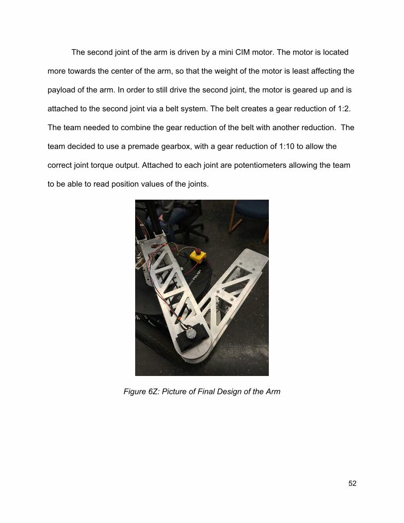
The second joint of the arm is driven by a mini CIM motor. The motor is located
more towards the center of the arm, so that the weight of the motor is least affecting the
payload of the arm. In order to still drive the second joint, the motor is geared up and is
attached to the second joint via a belt system. The belt creates a gear reduction of 1:2.
The team needed to combine the gear reduction of the belt with another reduction. The
team decided to use a premade gearbox, with a gear reduction of 1:10 to allow the
correct joint torque output. Attached to each joint are potentiometers allowing the team
to be able to read position values of the joints.
Figure 6Z: Picture of Final Design of the Arm
52

Figure 6AA: Rendering of Final Design of the arm with end effector
The end effector is designed to model a two finger pinching tool. Using a rack
and pinion system, the end effector can control how wide the gripper is open and closed
throughout functions the robot performs. The end effector is made using a 3D printer,
creating the two separate pieces that are combined through the rack and pinion system.
The pinion is driven using a Vex servo motor. Which allows the team to use more
precise position control of the end of arm tooling. Attached to the sliding piece is a linear
potentiometer giving another tool of precision for the manipulation of the end of arm
tooling. (Note: all the parts and components purchased and mentioned above are listed
in Appendix C with complete names and links to more details.) Below are some
sketches of the end effector design.
53
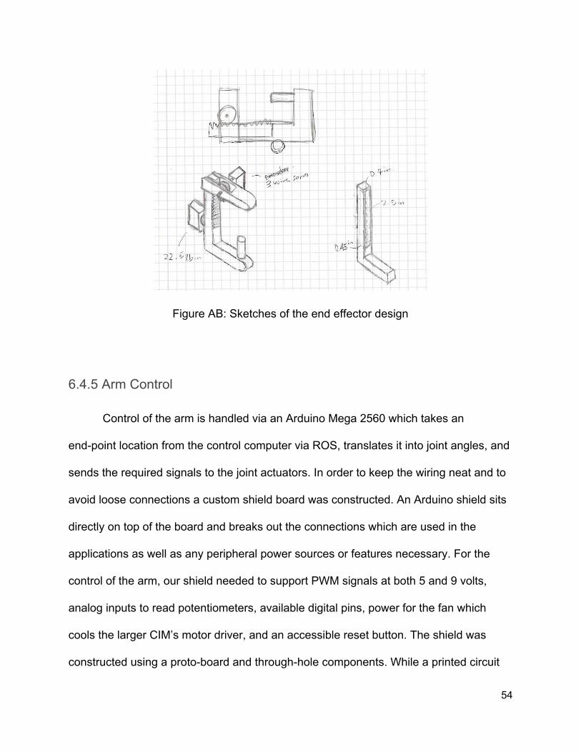
Figure AB: Sketches of the end effector design
6.4.5 Arm Control
Control of the arm is handled via an Arduino Mega 2560 which takes an
end-point location from the control computer via ROS, translates it into joint angles, and
sends the required signals to the joint actuators. In order to keep the wiring neat and to
avoid loose connections a custom shield board was constructed. An Arduino shield sits
directly on top of the board and breaks out the connections which are used in the
applications as well as any peripheral power sources or features necessary. For the
control of the arm, our shield needed to support PWM signals at both 5 and 9 volts,
analog inputs to read potentiometers, available digital pins, power for the fan which
cools the larger CIM’s motor driver, and an accessible reset button. The shield was
constructed using a proto-board and through-hole components. While a printed circuit
54
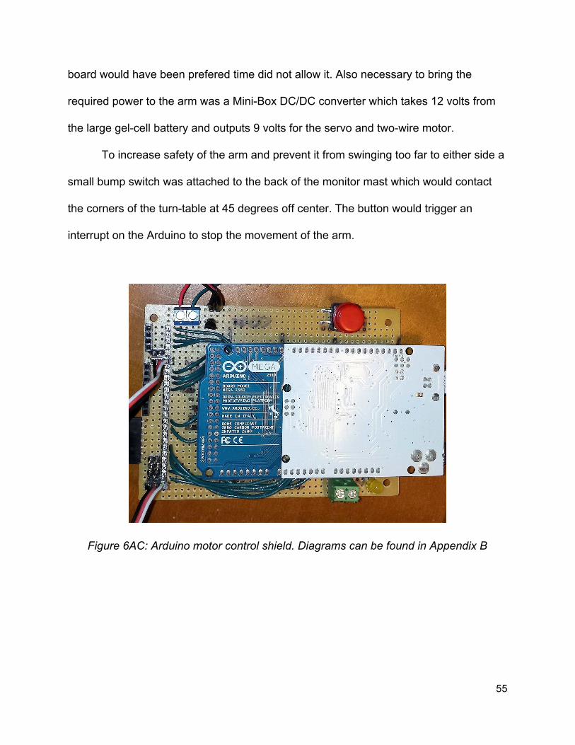
board would have been prefered time did not allow it. Also necessary to bring the
required power to the arm was a Mini-Box DC/DC converter which takes 12 volts from
the large gel-cell battery and outputs 9 volts for the servo and two-wire motor.
To increase safety of the arm and prevent it from swinging too far to either side a
small bump switch was attached to the back of the monitor mast which would contact
the corners of the turn-table at 45 degrees off center. The button would trigger an
interrupt on the Arduino to stop the movement of the arm.
Figure 6AC: Arduino motor control shield. Diagrams can be found in Appendix B
55

Figure 6AD: The motor drivers are on the right with the larger one inside an enclosure with a fan. On the left are the relays which separate power to the arm from the rest of
the robot.
Figure AE: The emergency bump switch for the turn-table.
56

7 Final Design Verifications
7.1 Segway Robot
This Segway RMP is a juxtaposition of parts from the RMP210 and RMP220 that
was donated to WPI’s AIM lab in 2011. Since then, the robot has been used in a
number of projects but had not been used for several years prior to this project.
7.1.1 Batteries
The platform currently utilizes three different batteries; two 74 volt batteries are
mounted to the base itself - one for powering the wheels and the other providing
auxiliary power - and one 12 volt gel-cell battery which sits on the platform. The original
design which was provided used four batteries but when getting the platform refurbished
we needed to consider cost and cut a second drive battery; both existing batteries are
refurbished and were provided by Segway in December 2016.
The gel-cell battery does most of the heavy lifting for the project, providing power
for both the computer and the arm. This is mainly because we need the peripherals to
be powered while the base is switched off or charging. Eventually, though, several
things can be moved to the auxiliary platform battery because the robot will be powered
on all together or not at all when deployed.
57


7.1.3 Driving
The Segway RMP communicates to the robot’s base computer through USB or
Ethernet by default. However, the USB drivers for Linux have not been updated for
newer versions of Ubuntu. In order to communicate with the platform, the team had to
connect over Ethernet. This is accomplished by leveraging a network switch and relying
on the RMP’s static IP.
Once connected, the base computer can send messages over Ethernet to the
RMP. These messages are sent using an RMP python node. This node is slightly
configured from the default node supplied by Segway. One such message conveys
linear and angular velocities to the wheel base. By sending different combinations of
linear and angular velocities, the team could successfully configure the robot to drive
any place they wanted.
7.2 System Architecture
The system architecture is built with the future in mind. The code is organized
into separate nodes or modules that perform one task and communicate through ROS
messages. This is a common design in ROS and object oriented programming in
general. By satisfying the single responsibility principle, the team was able to guarantee
that nodes should only have one reason to change. This should make it fairly easy to
maintain existing code while implementing new functionality.
59

Figure 7B: The current system architecture
Above is the current system architecture. Each box denotes a different node.
Each line denotes that a node is communicating with another node through ROS
messages. Some of these lines are two way communication but some of them only
require one way communication. In an effort to provide as much reasoning for each
node, the functionality for each node will be documented here.
As this project functions mostly as a foundation for future projects, the system
architecture must be easy to understand and extensible. The team designed a system
architecture thus that every node obeys the Single Responsibility Principle (SRP). The
node that controls the motion of the Segway wheels does not also calculate the path to
drive. Instead, another node is responsible for calculating the path of the robot and
sends proper linear and angular velocities to the driving node. The path planning node
60
acts as a controller for the driving node. This pattern is seen in several places
throughout the system seen below.
The aforementioned pattern is seen for driving, arm motion, opening a door,
operating an elevator, and controller the pan tilt system. Because of the high degree of
granularity and low degree of coupling that the SRP pattern provides, new
functionalities can easily be introduced into the system simply by launching new ROS
nodes, and having them subscribe to the main Communication node.
Setting up new features is simple and intuitive. If another project group wanted to
introduce another feature for other manipulation tasks, such as pouring a drink, they
could easily create a controller for that and send messages to the arm and driving
controllers. The low level driving and arm driving nodes should not need any changing
unless tuning is required. This is a key reason why we chose to separate out the system
architecture into many different ROS nodes.
7.2.1 Communications Node
The communications node parses commands sent by the user, through the
touchscreen interface, and sends commands to the appropriate controllers and nodes. It
facilitates all communication between the system and the end user interfaces but only
acts as an intermediate message parser and sender. Although this makes sending
commands simple, it becomes, in a way, a god class. God classes are often not
desirable but often make short term goals easier to achieve.
61

7.2.2 Eyes Controller
The eyes controller tells the pan tilt node when and to where to move the eyes
interface. In the future, it would be nice to be able to change the expression of the eyes,
like Baxter robots, depending on the user’s mood. This node could be extended to
include functionality for this while sending commands to update the eyes interfaces
through the communications node.
7.2.3 Directions Node
The directions node is designed to generate a map that shows a path from the
current position of the robot to another location within the environment. Right now, these
locations are manually added to the system.
7.2.4 Open Door Controller
The open door controller facilitates the coordination between the driving and arm
operation in order to open a door. This includes any sort of timing. Commands are sent
to the driving controller and arm driving controller at appropriate times to coordinate this
complex motion planning task.
7.2.5 Operate Elevator Controller
The open door controller facilitates the coordination between the driving and arm
operation in order to operate an elevator. This includes any sort of timing. Commands
are sent to the driving controller and arm driving controller at appropriate times to
62

coordinate this complex motion planning task. This node is similar to the open door
controller and commonality may be abstracted in the future.
7.2.6 Pan Tilt Node
The pan tilt node controls the servos that operate the pan tilt. This pan tilt moves
the eye interface. This node only takes in commands from the pan tilt controller and
executes those motions. There is no motion planning here.
7.2.7 Driving Controller
The driving controller sends commands to the driving node that are made up of
linear and angular velocities. The driving controller using path planning to figure out
which velocities to send to the driving node to arrive at a destination point from the
current position of the robot.
7.2.8 Driving Node
The driving node receives commands from the driving controller in the form of
angular and linear velocities. These velocities are sent to the Segway base so the base
will drive. There is not path planning done here.
7.2.9 Arm Controller
The arm controller sends messages to the arm driving node to move the arm.
The signals sent to the arm are calculated using inverse and forward kinematics.
63

7.2.10 Arm Driving Node
The arm driving node receives commands from the arm driving controller. These
velocities are sent to the Segway base so the base will drive. There is not path planning
done here.
7.2.11 Touchscreen Interface
The touchscreen interface is implemented as a localhost web page. It uses
HTML, CSS, and JavaScript to show the end user possible interactions. It uses onclick
events and server requests to send commands to the node server and the
communications node.
7.2.12 Node Server
The node server is used to host the local web server and serve the content for
the end user interface. It gives the team several tools for templating and easily
developing the user interface and is built using modern technologies.
7.2.13 Patient Database
The patient database is a cloud hosted database based on MongoDB. We
connect to this database through the Node.js server and a framework called Mongoose.
These tools make it very easy to connect, update, query, and delete database tables
and columns.
64

7.2.14 Eyes Interface
The eyes interface is another web based interface. The monitor for that interface
is attached to a mobile pan tilt system.
7.3 End User Interface
The end user interface is built on top of modern web technologies such as
HTML5, CSS3, JavaScript, and Node.js. The team chose to implement a web based
interface because then the end user interface is platform agnostic so long as there is
internet and a web browser. Several members of the team also had extensive web
development experience from past projects.
The team used Node.js and several other frameworks to hook into a database
and to make creating markup easier. Node.js is a modern web development framework
that helps in creating scaling applications and quick prototypes. It is much easier to
write templates than to repeat code that has already been written. However, this is not a
default capability in basic web development. By leveraging a framework called
Handlebars, the team could easily write new templates and web pages with little effort.
65

7.4 Arm
7.4.1 Machining the Links
In order to complete the design for the links of the arm, the team decided to
purchase a 48” by 4” sheet of aluminum with ⅜” thickness and machine the sheet to
fulfill the design specifications. With some consultation with the machine shop advisor,
the team came up with an appropriate plan for machining the parts. The link lengths
were 17 inches and 16 inches respectively for the 2 links in the arm. The 48 inch sheet
was therefore cut in half and prepared to be shaped and drilled for the link design. The
first link was drilled with a determined undersize hole for the press fit bearing. The
bearing would allow the vex shaft to fit inside. The first link was also cut round giving the
link a more appealing look. After testing out the links, it was determined that the weight
of the links might be a concern. The links were then machined to contain only necessary
structure and therefore the weight of the over links were reduced. The design of the
material reduction was based on a truss shape. The reduction of the material also gave
the arm an aesthetically appealing look, rather than just a solid block look. The links
were initially designed to be held together with standoffs, but aluminum extrudes were
used instead at the end because they are thicker and offer more structural stability.
66

Figure 7C: The final truss shaped aluminum links
7.4.2 First Joint Gearbox
The first link’s gearbox was designed and created, not premade. The team
calculated that the the necessary gear reduction required for the first link was about
1:20. The team designed a two stage gear box that used 4 gears with a 12, 48, 18, and
84 tooth gear, in that order. Using some spare acrylic, two supporting walls were made.
The walls were connected via 4 standoffs and the gears were installed using shafts
supported by bearings. The shafts within the gear box and used throughout the arm
design were VEX hex shafts. The team bought a three foot shaft and cut down to size
necessary shafts. The shafts and contact points inside of the gearbox used washers in
order to reduce friction when pieces were in motion. The gearbox was then mounted to
the underside of the segway base plate. The motor was mounted to one acrylic wall.
67
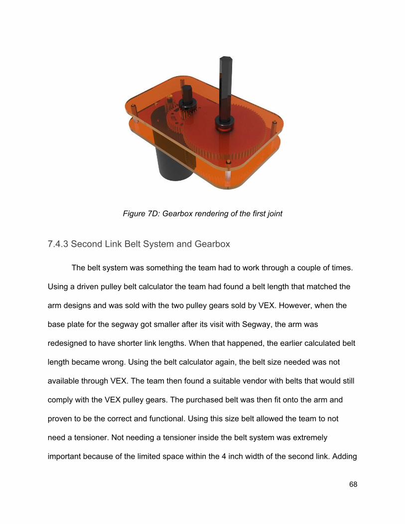
Figure 7D: Gearbox rendering of the first joint
7.4.3 Second Link Belt System and Gearbox
The belt system was something the team had to work through a couple of times.
Using a driven pulley belt calculator the team had found a belt length that matched the
arm designs and was sold with the two pulley gears sold by VEX. However, when the
base plate for the segway got smaller after its visit with Segway, the arm was
redesigned to have shorter link lengths. When that happened, the earlier calculated belt
length became wrong. Using the belt calculator again, the belt size needed was not
available through VEX. The team then found a suitable vendor with belts that would still
comply with the VEX pulley gears. The purchased belt was then fit onto the arm and
proven to be the correct and functional. Using this size belt allowed the team to not
need a tensioner. Not needing a tensioner inside the belt system was extremely
important because of the limited space within the 4 inch width of the second link. Adding
68

a necessary tensioner would have required more machining and careful design inside
the second link area.
The gearbox used for the second joint was planned to be made, but due to space
limitations, the team had to find an alternative option. The second joint needed a 1:10
gear reduction between the mini CIM motor that was to be used, and the 1:2 gear
reduction belt system that was going to be used to help drive the joint. The team found
a planetary gearbox sold by VEX that not only had the correct gear reduction, but was
also compatible with the mini CIM motor. The gearbox also fit within the space limitation
the arm offered.
7.4.4 Center Mast and Slider Mechanism
The arm was mounted onto a mast located at the center of the Segway base
plate. The mast was made of 4, 20 inch aluminum extrudes connected via brackets. The
extrudes were mounted to a rounded square aluminum plate, with a hex hub located at
the center of the plate. The aluminum plate sat on top of a lazy susan and allowed the
mast to rotate when driven by the first motor. The arm was connected to the mast via
sliders which allowed controlled placement of the height of the arm. By turning the
levers on the slider, the arm would lock into a permanent position. The slider design
allows teams to modify the robot's future purpose because the arm is so easily
removable. Other tools can be added to the arm with relative ease.
69

Figure 7E: The slider mast system
7.4.5 Potentiometer and Mounts
In order to get useful position data for the joints of the arm, the team decided to
use potentiometers on each joint. The first potentiometer is mounted underneath the
gearbox as shown in Figure zzz. The second potentiometer is attached to the “elbow” of
the arm, which is at the connection of the two links (Figure abc).
It was necessary to create an intermediate piece between the potentiometers
which normally handle much smaller shafts, and the larger hex shafts that the arm
contained. There were 2 different designs for different shafts. For each piece the
mount had two sockets. One socket connected to the shaft of the potentiometer and
the other connected to the joint shaft on the arm. The pieces were 3D printed as shown
below.
70

Figure 7F: 1st joint gearbox with potentiometer mounted
Figure 7G: Picture of potentiometer mount on second joint
71

8 Final Design Validation
8.1 Mandatory Goals
8.1.1 Teleoperation
The Segway RMP effectively drives around the environment through
teleoperation. The team was able to adapt code used in the default Turtlebot packages
to work with the Segway RMP such that a user can drive the robot through arrow keys
on a keyboard. This keyboard can either be connected directly to the robot’s computer
or can be on a computer that has remotely connected to the onboard computer through
SSH or some equivalent.
8.1.2 Safety
The Segway RMP has been cleaned up and organized such that there are no
loose parts or exposed wires. The inside of the platform has been simplified and
hollowed out to allow easy access to control board, power boards, and the onboard
computer. The old arm has been replaced. The RMP is much safer than at the
beginning of this project.
72

8.1.3 Navigation and Mapping
The Segway RMP can effectively map its environment through the use of a
LIDAR and a ROS package called Hector. This package takes laser scan data and
generates a map, without needing odometry data. The Segway RMP can perform
simple autonomous driving if given a goal destination on the map.
8.1.4 Arm
The Segway RMP is now equipped with a new arm specifically designed to open
the doors in the HDI. It is a much stronger and more robust arm than previous iterations.
It is controlled through a closed loop algorithm running on an Arduino. The arm has not
been used to open doors or operate elevators. It has been tested to ensure that it
moves properly with this controller.
8.1.5 Simple Touchscreen Interface
The platform has a new touchscreen interface and a new UI used for interacting
with the robot. Users can touch tap targets on the screen and use the on screen
keyboard to interact and issue commands. The UI is simple, intuitive, has simple
language and has large touch targets. This user interface has been evaluated in the
form of a user survey and has been subject to quality assurance testing along the way.
The interface proved to be clear based on the survey results and has no known bugs
that break functionality.
73

8.2 Reasonable Goals
8.2.1 Obstacle Avoidance
The team was unable to implement obstacle avoidance. The autonomous driving
functionality of the robot is very simple as it stands and simply proceeds from one point
to another with little regards for what occupies space between those points. In the
future, the team recommends that this functionality be implemented using standard
SLAM practices.
8.2.2 Improved End User Interface
In a survey, the team was able to find which parts of the UI were confusing and
which parts were more understandable. The team altered the design based on feedback
from these surveys. The team also expanded check in functionality and simplified the
overall design in an effort to improve user experience.
8.2.3 Patient Information Database
The team was able to connect the web server to a cloud database hosted on
MongoLab. It is MongoDB and hold information about patients such as their name,
gender, and their current check in status. Connecting and running queries to the
database is simple through modern frameworks such as NodeJS and Mongoose.
74
8.2.4 Able to Open Door or Curtain
The team was unable to accomplish this goal. This maneuver is extremely
complicated and, although the team was able to implement basic arm control, the
platform cannot currently open a door by itself.
8.2.5 Aesthetic Chassis Design
Although the Segway RMP is in a much more aesthetically pleasing place than it
was at the start of this project, the team suggest that future teams continue to improve
the appearance of the robot so that users are not intimidated by the robot and are
comfortable approaching the platform.
8.3 Reach Goals
8.3.1 Facial Recognition and Identification
The team was unable to accomplish this goal.
8.3.2 Able to Help Fill Out Patient Paperwork
The team was able to implement a simple version of this functionality. A patient
who has not yet been registered in the system can enter their first name, last name, and
gender to be added to the system. They can then check in as normal for future visits. In
the future, the team recommends that this functionality be explored and expanded to
include more detailed information typically on a registration form. However, the team
75

warns about the potential security issues of hosting this information on a MongoDB
instance on a cloud database system.
8.3.3 Intelligently Plan Patient Room Assignments
The team was unable to accomplish this goal.
8.3.4 Smarter Obstacle Avoidance
The team was unable to accomplish this goal.
8.3.5 Voice Recognition and Natural Language Processing
The team was unable to accomplish this goal.
9 Discussion
9.1 Segway Robot
As was stated before, the Segway RMP had fallen into disrepair over the years
and we were faced with a difficult situation; we had a project, but nothing on which to
build it. It was our original plan to build on existing hardware to perform specific tasks,
but the troubles with the platform focused our intention differently. Because the RMP
was in need of repair we began to focus on preventing the same difficulties for the
previous team. We realized that it was important that we left behind us a usable, clean,
documented platform which could be used for a variety of future projects.
76

Because we had to start from scratch with the electronics we were able to
carefully plan and document everything that was done. In contrast to the previous team,
we avoided the use of breadboards which often result in disconnected wires with no
way to tell how to reconnect them. Instead of breadboards to make connections
between the control components (those being the computer and the Arduino) and the
motor drivers and other peripherals we used through-hole proto-boards so that the
components can be removed and rewired easily. We were also able to build a computer
with future applications in mind. We researched the minimum recommended system
requirements for our various reach goals to ensure that the computer would be useful to
future teams. In the end we had built a platform which not only works but is easily
extensible.
9.2 System Architecture
The robot now has a documented backend system that requires minimal
modification of existing code to add or change functionality. Because the system
architecture has been designed in a modular way, following the Single Responsibility
Principle, the robot is now in a place where only a few lines need to be added to the
main system server in order to hook up new functionality nodes. The robot is in a much
better place than we left it in with respect to the coupling of the code. As a result, less
time will need to be spent by future groups to get the basics going, and more time can
be spent by them towards achieving more advanced and functions.
77

9.3 End User Interface
The system now has a functional end user interface built user modern technology
in web development. The interface is connected to ROS and the rest of the robot over
websockets. As stated before, these choices mean that the interface is not only platform
agnostic but also very easy to improve. Web development allows for very quick and
simple changes to have a drastic effect on the look and feel of the application. This
amount of power gives the developer a lot of freedom in what to implement and how to
do it.
Looking forward, the robot’s new interactions, such as issuing directions to a
user, should be fairly easy to add and improve iteratively. Future projects can easily edit
the interface and its functionalities if they find the use cases that this team predicted
were not important or were not applicable for their project.
Finally, the largest implication of the end user interface is that users can now
interact with the robot and change its behavior based on their input. This is incredibly
important if this robot is going to be useful in any applications.
9.4 Arm
The Segway RMP platform now has a robust robotic arm capable of many
functions. The current design for the arm keeps both the segway platform and the arm
versatile and capable of relative easy modifications. If the robot needs to change
environments, where door handle heights are different from the previous, the slider
78

mechanism on the mast allows for an easy adjustment. The slider mechanism also
allows the arm to be easily removed. This gives the robot the ability for easier
transportation due to the reduction of weight, and protection of the arm during transit.
The easy removal also allows future teams the capability to remove the arm and attach
another designed tool. While that ability is possible, there should be no need for the arm
to be detached. The current condition of the arm leaves an abundance of possibilities of
function and applications. Immediate applications include opening doors and operating
elevators, both tasks that the arm was designed to complete. With the completion of
these task, the robot gains an increased level of mobility throughout the global map.
Other possible functions include making gestures, transporting food or medicine, and
moving small objects like carts.
The arm also has the convenience of a simple design. The math and
calculations of the arm are relatively simple, yet as mentioned maintains a high potential
purpose. The arm can also be modified to increase the number of degrees of freedom
or the end effector on the arm can be changed. The current arm balances functionality
with simplicity.
9.5 Challenges
9.5.1 Segway RMP
When our group inherited the RMP, it had been allowed to sit without being
charged or powered on for more than a year resulting in battery damage. We did not
79

know about it until the project was well underway and had to spend several weeks trying
to find a solution. At first we assumed that the problem was with the batteries
themselves so we rotated them, trying different batteries in different positions as well as
batteries borrowed from another lab’s RMP. Once it was established that the batteries
were well below the 50V point where the CCU begins to have trouble charging them, we
looked into options to replace or revive them. The price for one new battery from
Segway came in at around $900 while used and refurbished ones were anywhere from
$500-$800. There were also companies that would refurbish or rebuild the batteries we
had for a lower price, but shipping the batteries as hazardous material would have
added to the cost. Given our allotted MQP budget, acquiring a new battery was not a
possibility.
The same company which would have rebuilt the batteries also had available a
custom battery charger which is designed to plug directly into the battery allowing it to
be trickle charged (charged at a slow rate) to the point where the CCU would be able to
take over. An important caveat with this tool is that it came with a limited number of
uses, after which it would no longer operate. The initial cost of the tool was $500 for
three uses, but it also featured a rebate which brought the actual cost down to a much
more affordable $150. The battery reconditioner was ordered and used as directed on
the three batteries but did not have the desired effect. When we were finally out of
options, our contact at Segway, Chris Crimmins, offered to take a look at the RMP over
winter break. He discovered an issue with the charging circuitry for one of the batteries
and confirmed that the batteries we had were beyond saving. He upgraded the
80

firmware, fixed the charging circuitry, installed a second caster wheel, the new frame
and top plate, and replaced two of the batteries. Finally, at the start of our third of three
terms on the project, we had hardware which was operable.
The RMP came wired with two I/O methods for the computer to communicate
with it over: USB and Ethernet. Because a driver did not exist for Ubuntu 16.04 to allow
the RMP to connect over USB, we instead went for the OS-agnostic Ethernet-connected
option. To achieve this connection, we plugged the RMP ethernet cable into a router,
which was then plugged into the back of the robot computer. This method worked rather
well for some time. However, When we registered the computer for the wireless
network, the router suddenly became unable to locate the RMP on its LAN network. A
week was spent debugging what went wrong; a plethora of network diagnostic and
device manager tools were used to try and locate the RMP on the network. We also
brought in a peer who specializes in networking to help us diagnose the issue.
Unfortunately, all of our best efforts were for naught. Because the RMP was still able to
connect to our laptops which were running Windows, we decided that the issue must be
some deep system setting within our Ubuntu OS. We ultimately did a fresh install of
Ubuntu 16.04 to reset all network settings, which resolved the issue.
Further debugging eventually revealed that the RMP was flushing its
configuration files on every power cycle, and required that new config file be uploaded
on each boot. Because this configuration file is what allows the RMP to connect over
ethernet, and because the RMP USB driver for Ubuntu is outdated, the only way to get
a new configuration file onto the RMP seems to be by uploading it via USB from a
81

Windows machine. Once this is done, the RMP can connect over ethernet to the Ubuntu
machine without any difficulty.
9.5.2 Software
While the software headaches paled in comparison to the one presented by the
RMP, there were still a few snags along the way. Most notably, the way we integrated
our front and back ends revealed an interesting bug in the way ROS does garbage
collection. Firstly, garbage collection in ROS seemed to be handled by comparison,
merely looking to see if a resources had the same handle as the resource that was set
to be cleared from memory. Secondly, garbage collection seemed to take a non-trivial
amount of time. This quirk manifested itself when the system architecture closed and
opened a websocket of the same name to the same address, such as during a page
refresh or loading between pages. When this happened, both the old and new socket
connections would be cleared, resulting in a severing of the connection between the
front and back ends. To solve this, a minor tweak was made to the ROSlib source code
to simply prevent it from clearing out closed connections during runtime. In doing so, the
socket connection never gets flagged for deletion, even during its momentary lapse in
activity.
Constructing a map using LIDAR also proved to be more difficult than initially
anticipated. To generate a map of our surroundings to use for autonomous navigation,
we opted to use a package called Hector SLAM in conjunction with our Hokuyo LIDAR
module. Hector was chosen because it would, in theory, allow us to generate a map
82

using only LIDAR data, without need for odometry. Connecting the LIDAR proved
simple enough. However, when Hector tried to generate a map, it would only do so
using the first sweep of LIDAR data, and would not update the map to reflect new
batches of LIDAR data coming in. As it turned out, what was happening was that the
ROS launch file we had constructed was not properly importing all the resources it
needed, and the map was, in fact, parsing new LIDAR data, just in an unexpected way.
Instead, the pieced-together configuration was only updating the map for unexplored
areas, while also not performing odometry. This resulted in basic tests making it seem
as though new data was not being processed, while in fact the new data was just
appeared to be the same as the old data to the robot. Through some heavy
trial-and-error, we were able to piece together a far more complete launch file and
generate a functional map of our lab space.
9.5.3 Hardware
One of the major problems encountered while completing the manufacturing of
the arm was the time needed during machining. Consultation of how to machine the
raw sheets of aluminum took a week's time. Then due to the lab’s availability the
completion of the manufacturing took a considerable longer time than the team has
planned for.
While building the first link’s gearbox there was an interference problem between
one of the hex shafts and the CIM motor. Whenever the gearbox was being turned the
shaft would collide with the motor and stop rotation. In order to solve the problem, the
83

shaft was rounded down to rid the corners and create clearance. This solution was was
acceptable because this part of the shaft was outside the functioning gearbox and
therefore did not affect the gear reduction process.
10 Conclusions and Recommendations
10.1 Segway RMP
To avoid future complications with the Segway RMP base, it is recommended to
make sure that the battery is well maintained and charged at least once a month, even
when not in use. Failure to do this was what is suspected to have caused the decrepit
state of the RMP when our team inherited it, so it bears repeating: make sure the
battery is well maintained.
As far as developmental recommendations for future groups, one aspect of the
design that could use improvement is the chassis layout. Currently, the wires are
managed well enough, but are still largely exposed, as are the power supply units.
Furthermore, the robot itself is rather heavy and, being made of metal, yields a large
force of impact even when operating at low speeds. This produces a somewhat unsafe
and unsightly environment for public uses. As such, future teams may wish to look into
making a chassis cover or case that conceals these features while also cushioning
bystanders from potential impacts. These design considerations would result in a safer
and more aesthetic robot overall.
84

A third recommendation, as far as the Segway RMP goes, is to investigate how
to get odometry data out of it. Unfortunately, by the time we were able to get the RMP to
power on, we no longer had enough time to learn how to do this with it, and instead
relied on LIDAR to do SLAM. As a result, our ability to navigate autonomously was
severely crippled, as the robot often lost itself without proper odometry data to keep
track of itself with. By learning how to extract more reliable odometry data out of the
RMP, autonomous driving should prove to be much easier in future iterations.
10.2 Software
One of the driving principles behind the software design for this platform was to
impose a high degree of granularity on the system, such that the platform could easily
be repurposed for future unforeseen tasks. The core thing to keep in mind when looking
to expand the backend system is that it exists as an interface between ROS and the
platform-agnostic front-end. As such, the actual implementation of any given
component’s functionality can easily be refactored, and new functionalities can be easily
hooked up. In brief, all a developer would need to do is update the existing event
handler callback to have cases for whatever new events they want to send between
ROS and the front-end UI. For a more in-depth dissection of exactly how to do that,
consult the attached readme markdown file.
85

10.3 Hardware
The mount of the first gear of the arm could be better constructed. Currently
there is a concern with the integrity of gearbox mount strength when the arm is being
operated. A better devised method of fixing the first joint gearbox to the underside of
the segway plate would greatly increase the functional life of the arm.
The central mast where the arm is mounted could also stand to be improved by
future groups, if they find it necessary. Currently, the system of bearings underneath the
mast are sub-optimal, and as a result the mast does not sit completely flush with the
RMP base. Therefore, when equipped with a decently heavy payload such as the arm,
the central mast tends to lean, which in turn puts an undue amount of strain on the
gearbox below.
In the future it would benefit the project to create printed circuit boards based on
the protoboards currently in use. This would allow boards to be easily changed or
reordered in case of damage. Other items could improve the integrity of the wiring
including switching to appropriately sized ribbon cables and headers.
There are also several potential improvements for the arm. The team
recommends improving the current design of the end effector and attaching that onto
the arm. The current end effector is not attached to the robot but is designed to latch
onto door handles and rotate the handle. The team also recommends designing an end
effector capable of pressing elevator buttons effectively. This design can introduce
fingers that help to press buttons that may be at different elevations.
86

Finally, the team strongly recommends taking the foundation built here and using
it to implement functionality for opening doors. Opening doors is an incredibly difficult
endeavor and the team suggests to start with a known environment and work out from
there. The team has come up the following steps (Figure 10A) for the robot to open
doors, and suggest future groups to use similar strategies as the foundation of
completing door opening in this manner has already been laid.
Figure 10A: Sketch of steps taken by the robot to complete door opening
87

11 References Sayer, P. (2016). Belgian Hospital turns to robots to receive patients. Retrieved from
http://www.cio.com/article/3085211/belgian-hospitals-turn-to-robots-to-receive-patients.html LeBlanc, N., Patel, K., & Rashid, S. (2012). Guest Orientation Assistance and Telepresence Robot.
Worcester, MA. Fischer, G., & LeBlanc, N. (2012). Tour Guide Robot Interactions. Fong, T., Nourbakhsh, I., & Dautenhahn, K. (2003). A survey of socially interactive robots. In Robotics
and Autonomous Systems . http://doi.org/10.1016/S0921-8890(02)00372-X Wistort, R. (2010, March). “Only Robots on the Inside.” Interactions Magazine , 72–74. Retrieved from
http://robotic.media.mit.edu/wp-content/uploads/sites/14/2015/01/p72-wistort.pdf Gombolay, M., Yang, X. J., Hayes, B., Seo, N., Liu, Z., Wadhwania, S., … Shah, J. (2016). Robotic
Assistance in Coordination of Patient Care. http://www.roboticsproceedings.org/rss12/p26.pdf Peterson, L., Austin, D., & Kragic, D. (2000). High-level control of a mobile manipulator for door opening.
Proceedings. 2000 IEEE/RSJ International Conference on Intelligent Robots and Systems (IROS 2000) (Cat. No.00CH37113), 3 (FEBRUARY 2000), 2333–2338. http://doi.org/10.1109/IROS.2000.895316
Tai, L. J., Rae, W., Nunn, J., & Larochelle, P. (2009). Design and Implementation of Building Navigational
Tools for the PantherBot Mobile Robot. Advances. Klingbeil, E., Saxena, A., & Ng, a Y. (2010). Learning to open new doors. 2010 IEEE/RSJ International
Conference on Intelligent Robots and Systems, 2751–2757. http://doi.org/10.1109/IROS.2010.5649847
Kang, J., Hwang, C., Park, G. T., & Robotics, I. (n.d.). A Simple Control Method for Opening a Door with
Mobile Manipulator, (1), 1593–1597. Chitta, S., Cohen, B., & Likhachev, M. (2010). Planning for autonomous door opening with a mobile
manipulator. Proceedings - IEEE International Conference on Robotics and Automation , 1799–1806. http://doi.org/10.1109/ROBOT.2010.5509475
Klingbeil, E., Carpenter, B., Russakovsky, O., & Ng, A. Y. (2010). Autonomous operation of novel
elevators for robot navigation. Proceedings - IEEE International Conference on Robotics and Automation , 751–758. http://doi.org/10.1109/ROBOT.2010.5509466
Troniak, D., Sattar, J., & Gupta, A. (2013). Charlie Rides the Elevator--Integrating Vision, Navigation and
Manipulation towards Multi-floor Robot Locomotion. 2013 International Conference on Computer and Robot Vision (CRV) , 1–8. Retrieved from http://ieeexplore.ieee.org/xpls/abs_all.jsp?arnumber=6569177
Robotics Kinematics and Dynamics/Serial Manipulator Statics (2016). WikiBooks.
https://en.wikibooks.org/wiki/Robotics_Kinematics_and_Dynamics/Serial_Manipulator_Statics
88
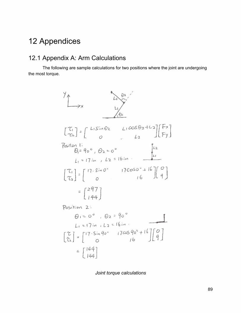
12 Appendices
12.1 Appendix A: Arm Calculations The following are sample calculations for two positions where the joint are undergoing
the most torque.
Joint torque calculations
89
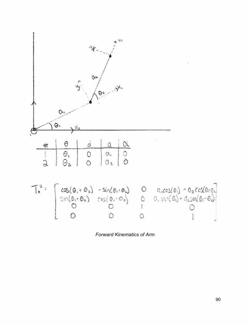
Forward Kinematics of Arm
90

Inverse Kinematics of the Arm
91

12.2 Appendix B: Electrical System
Overview of the onboard electrical system
92

An overview of the electrical control system for the arm
93

An overview of the custom arduino shield used for the arm controller. Pin breakout is listed below.
94

Arduino Pin Number / Mode Connection
PWM 7 Small CIM PWM
Digital 22 Small CIM Direction
Digital 26 / Enable High Small CIM !Sleep
AI 5 Small Current Sense
AI 4 Big CIM Current Sense
PWM 5 Big CIM PWM High
PWM 4 Big CIM PWM Low
Digital 24 Big CIM Direction
95

12.3 Appendix C: Resources and Components
Item Description Link
Computer
RAM PNY Anarchy 8GB kit https://www.amazon.com/dp/B012DT0IB6/
Case MITXPC Mini ITX https://www.amazon.com/dp/B01B575EMA/
Motherboard MSI AMD A68H Mini ITX https://www.amazon.com/dp/B011TX1JF6/
Monitor Asus VT207N Touch Screen https://www.amazon.com/dp/B00LX7M2RI/
CPU AMD A8-7600 https://www.amazon.com/dp/B00LUH1N4O/
HDD Kingston 2.5 inch SATAIII SSD https://www.amazon.com/dp/B01FJ4UL2S/
Motor Drivers Note: May not be the exact product but the carrier boards are the same for the same class of MOSFET
Large Pololu High-Power Motor Driver 24v23 CS
https://www.pololu.com/product/1456
Small Pololu G2 High-Power Motor Driver 24v13
https://www.pololu.com/product/2992
Other
Segway RMP RMP 210 https://drive.google.com/open?id=0B1dK_aU5gJWQVDJsNUZBR2U5MFk
Computer Power Supply Mini-Box M4-ATX http://www.mini-box.com/M4-ATX
DCDC converter Mini-Box DCDC-USB http://www.mini-box.com/DCDC-USB
96

Item Description
Arm
Cim motor http://www.vexrobotics.com/217-2000.html
Cim motor gears
http://www.vexrobotics.com/vexpro/motion/vexpro-gears/cim-m
otor-gears.html
48t Gear with 1/2" Hex Bore & VersaKeys
http://www.vexrobotics.com/vexpro/motion/vexpro-gears/1-2-hex-bore.html
18t Gear with 1/2" Hex Bore
84t Gear with 1/2" Hex Bore
1/2" Hex Stock (3 feet)
http://www.vexrobotics.com/shaft-stock.html
1/2" ThunderHex Stock (18 inches)
Clamping Shaft Collar - 1/2" Hex ID
http://www.vexrobotics.com/vexpro/hardware/shaft-collars.html
Timing Pulley (HTD 5mm) - 18T, 9mm Double Flange, 1/2" Hex
http://www.vexrobotics.com/vexpro/motion/belts-and-pulleys/htd
pulleys.html
Timing Pulley (HTD 5mm) - 36T, for 15mm or (2X) 9mm Timing Belts, 1/2" Hex
Timing Belt (HTD 5mm) - 225T, 9mm Wide
http://www.vexrobotics.com/vexpro/motion/belts-and-pulleys/htd
belts9.html
8mm to 1/2" Hex Adapter http://www.vexrobotics.com/vexpro/hardware/217-3255.html
97
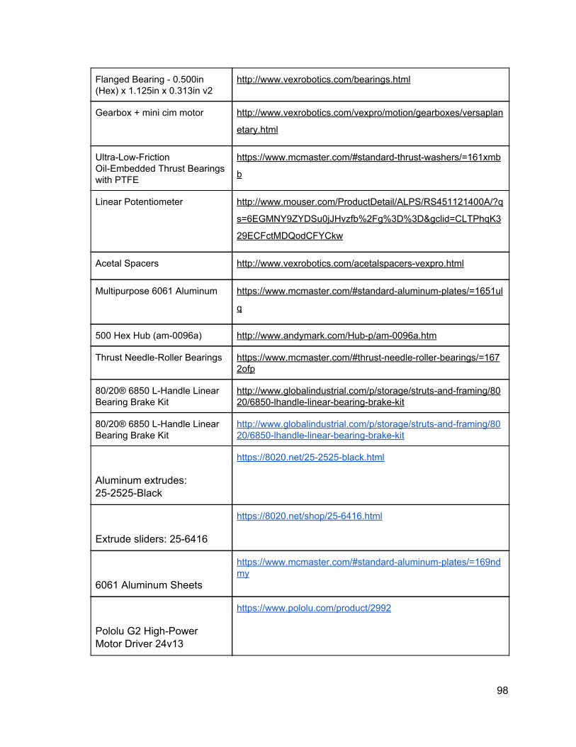
Flanged Bearing - 0.500in (Hex) x 1.125in x 0.313in v2
http://www.vexrobotics.com/bearings.html
Gearbox + mini cim motor http://www.vexrobotics.com/vexpro/motion/gearboxes/versaplan
etary.html
Ultra-Low-Friction Oil-Embedded Thrust Bearings with PTFE
https://www.mcmaster.com/#standard-thrust-washers/=161xmb
b
Linear Potentiometer http://www.mouser.com/ProductDetail/ALPS/RS451121400A/?q
s=6EGMNY9ZYDSu0jJHvzfb%2Fg%3D%3D&gclid=CLTPhqK3
29ECFctMDQodCFYCkw
Acetal Spacers http://www.vexrobotics.com/acetalspacers-vexpro.html
Multipurpose 6061 Aluminum https://www.mcmaster.com/#standard-aluminum-plates/=1651ul
q
500 Hex Hub (am-0096a) http://www.andymark.com/Hub-p/am-0096a.htm
Thrust Needle-Roller Bearings https://www.mcmaster.com/#thrust-needle-roller-bearings/=1672ofp
80/20® 6850 L-Handle Linear Bearing Brake Kit
http://www.globalindustrial.com/p/storage/struts-and-framing/8020/6850-lhandle-linear-bearing-brake-kit
80/20® 6850 L-Handle Linear Bearing Brake Kit
http://www.globalindustrial.com/p/storage/struts-and-framing/8020/6850-lhandle-linear-bearing-brake-kit
Aluminum extrudes: 25-2525-Black
https://8020.net/25-2525-black.html
Extrude sliders: 25-6416
https://8020.net/shop/25-6416.html
6061 Aluminum Sheets
https://www.mcmaster.com/#standard-aluminum-plates/=169ndmy
Pololu G2 High-Power Motor Driver 24v13
https://www.pololu.com/product/2992
98

12.4 Appendix D: Authorship and Contributions
Section Author(s)
1 Abstract Jacob Hackett
2 Executive Summary Jacob Hackett
3 Introduction Jacob Hackett
4 Literature Review Joe Fainer, Erin Leger
5 Project Strategy Jacob Hackett
5.1 Initial Problem Statement Jacob Hackett
5.2 Objectives and Constraints Jacob Hackett
5.3 Project Approach Jacob Hackett, Tom Farro
6.1 Needs Analysis All
6.2 Prototyping/Modeling All
6.3 Alternative Designs All
6.4 Final Design Selection All
7.1 Segway Robot Erin Leger, Tom Farro
7.2 System Architecture Jacob Hackett
7.3 End User Interface Jacob Hackett
7.4 Arm Joe Fainer, Emily Yu
8.1 Mandatory Goals Jacob Hackett
8.2 Reasonable Goals Jacob Hackett
8.3 Reach Goals Jacob Hackett
9.1 Segway Robot Erin Leger, Tom Farro
9.2 System Architecture Jacob Hackett, Tom Farro
9.3 End User Interface Jacob Hackett, Tom Farro
99
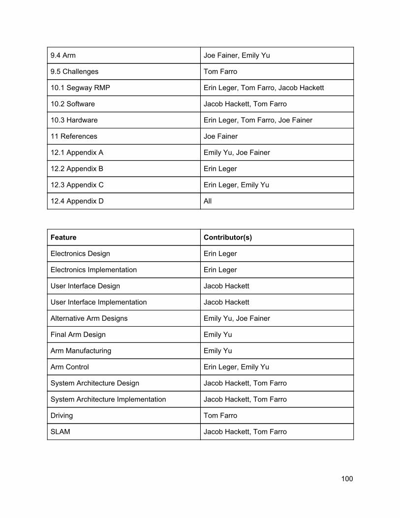
9.4 Arm Joe Fainer, Emily Yu
9.5 Challenges Tom Farro
10.1 Segway RMP Erin Leger, Tom Farro, Jacob Hackett
10.2 Software Jacob Hackett, Tom Farro
10.3 Hardware Erin Leger, Tom Farro, Joe Fainer
11 References Joe Fainer
12.1 Appendix A Emily Yu, Joe Fainer
12.2 Appendix B Erin Leger
12.3 Appendix C Erin Leger, Emily Yu
12.4 Appendix D All
Feature Contributor(s)
Electronics Design Erin Leger
Electronics Implementation Erin Leger
User Interface Design Jacob Hackett
User Interface Implementation Jacob Hackett
Alternative Arm Designs Emily Yu, Joe Fainer
Final Arm Design Emily Yu
Arm Manufacturing Emily Yu
Arm Control Erin Leger, Emily Yu
System Architecture Design Jacob Hackett, Tom Farro
System Architecture Implementation Jacob Hackett, Tom Farro
Driving Tom Farro
SLAM Jacob Hackett, Tom Farro
100