
HOSPIRA - medonegroup.com · technical support operations electronic technical service manual...
278
TECHNICAL SUPPORT OPERATIONS ELECTRONIC TECHNICAL SERVICE MANUAL TECHNICAL SUPPORT OPERATIONS ELECTRONIC TECHNICAL SERVICE MANUAL EPS-00587-008 (REV. 2/05) HOSPIRA Infusion Systems Plum XL Series
Transcript of HOSPIRA - medonegroup.com · technical support operations electronic technical service manual...

TECHNICAL SUPPORT OPERATIONS
ELECTRONIC TECHNICAL SERVICE MANUAL
TECHNICAL SUPPORT OPERATIONS
ELECTRONIC TECHNICAL SERVICE MANUAL
EPS-00587-008 (REV. 2/05)
HOSPIRA
Infusion Systems
Plum XL Series
For use with the following list numbers:
Technical Service Manual
Plum XL 11555-04, 12570-04LifeCare XL 11555-09, 11555-13, 11555-27, 11555-29, 11555-36,
11555-46, 11555-54, 11555-88 Plum XLM 11846-04
LifeCare XLM 11846-09, 11846-27, 11846-29, 11846-36, 11846-42, 11846-46, 11846-54, 11846-88
Plum XLMwith DataPort
11859-04
Plum XLMwith DataPort
Veterinary
12570-04
LifeCare XLMwith DataPort
11859-09, 11859-27, 11859-29, 11859-36, 11859-42, 11859-54, 11859-63, 11859-69, 11859-71, 11859-88
430-00587-008 (Rev. 2/05)

430-00587-008 (Rev. 2/05) Plum XL Series
© 2005 Hospira, Inc.
This document and the subject matter disclosed herein are proprietary information. Hospiraretains all the exclusive rights of dissemination, reproduction, manufacture, and sale. Any partyusing this document accepts it in confidence, and agrees not to duplicate it in whole or in partnor disclose it to others without the written consent of Hospira.
Technical Service Manual i 430-00587-008 (Rev. 2/05)
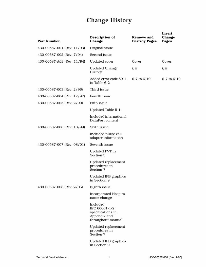
Change History
Part NumberDescription of Change
Remove and Destroy Pages
Insert Change Pages
430-00587-001 (Rev. 11/93) Original issue
430-00587-002 (Rev. 7/94) Second issue
430-00587-A02 (Rev. 11/94) Updated cover Cover Cover
Updated Change History
i, ii i, ii
Added error code 59-1 to Table 6-2
6-7 to 6-10 6-7 to 6-10
430-00587-003 (Rev. 2/96) Third issue
430-00587-004 (Rev. 12/97) Fourth issue
430-00587-005 (Rev. 2/99) Fifth issue
Updated Table 5-1
Included international DataPort content
430-00587-006 (Rev. 10/99) Sixth issue
Included nurse call adapter information
430-00587-007 (Rev. 08/01) Seventh issue
Updated PVT in Section 5
Updated replacement procedures in Section 7
Updated IPB graphics in Section 9
430-00587-008 (Rev. 2/05) Eighth issue
Incorporated Hospira name change
Included IEC 60601-1-2 specifications in Appendix and throughout manual
Updated replacement procedures in Section 7
Updated IPB graphics in Section 9

CHANGE HISTORY
430-00587-008 (Rev. 2/05) ii Plum XL Series
This page intentionally left blank.
Technical Service Manual iii 430-00587-008 (Rev. 2/05)
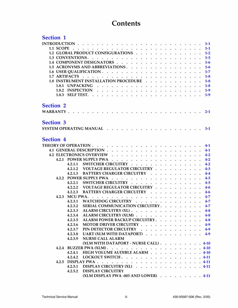
Contents
Section 1INTRODUCTION . . . . . . . . . . . . . . . . . . . . . . . . . . 1-1
1.1 SCOPE . . . . . . . . . . . . . . . . . . . . . . . . . . . 1-11.2 GLOBAL PRODUCT CONFIGURATIONS . . . . . . . . . . . . . . 1-21.3 CONVENTIONS . . . . . . . . . . . . . . . . . . . . . . . . 1-51.4 COMPONENT DESIGNATORS . . . . . . . . . . . . . . . . . . 1-61.5 ACRONYMS AND ABBREVIATIONS . . . . . . . . . . . . . . . . 1-61.6 USER QUALIFICATION . . . . . . . . . . . . . . . . . . . . . 1-71.7 ARTIFACTS . . . . . . . . . . . . . . . . . . . . . . . . . 1-81.8 INSTRUMENT INSTALLATION PROCEDURE . . . . . . . . . . . . 1-8
1.8.1 UNPACKING . . . . . . . . . . . . . . . . . . . . . . 1-81.8.2 INSPECTION . . . . . . . . . . . . . . . . . . . . . . 1-91.8.3 SELF TEST. . . . . . . . . . . . . . . . . . . . . . . . 1-9
Section 2WARRANTY . . . . . . . . . . . . . . . . . . . . . . . . . . . . 2-1
Section 3SYSTEM OPERATING MANUAL . . . . . . . . . . . . . . . . . . . . 3-1
Section 4THEORY OF OPERATION . . . . . . . . . . . . . . . . . . . . . . . 4-1
4.1 GENERAL DESCRIPTION . . . . . . . . . . . . . . . . . . . . 4-14.2 ELECTRONICS OVERVIEW . . . . . . . . . . . . . . . . . . . 4-2
4.2.1 POWER SUPPLY PWA . . . . . . . . . . . . . . . . . . . 4-24.2.1.1 SWITCHER CIRCUITRY . . . . . . . . . . . . . . . 4-24.2.1.2 VOLTAGE REGULATOR CIRCUITRY . . . . . . . . . . 4-34.2.1.3 BATTERY CHARGER CIRCUITRY . . . . . . . . . . . 4-4
4.2.2 POWER SUPPLY PWA . . . . . . . . . . . . . . . . . . . 4-54.2.2.1 SWITCHER CIRCUITRY . . . . . . . . . . . . . . . 4-54.2.2.2 VOLTAGE REGULATOR CIRCUITRY . . . . . . . . . . 4-64.2.2.3 BATTERY CHARGER CIRCUITRY . . . . . . . . . . . 4-6
4.2.3 MCU PWA. . . . . . . . . . . . . . . . . . . . . . . . 4-74.2.3.1 WATCHDOG CIRCUITRY . . . . . . . . . . . . . . 4-74.2.3.2 SERIAL COMMUNICATION CIRCUITRY . . . . . . . . . 4-74.2.3.3 ALARM CIRCUITRY (XL) . . . . . . . . . . . . . . . 4-84.2.3.4 ALARM CIRCUITRY (XLM) . . . . . . . . . . . . . . 4-84.2.3.5 ALARM POWER BACKUP CIRCUITRY . . . . . . . . . . 4-84.2.3.6 MOTOR DRIVER CIRCUITRY . . . . . . . . . . . . . 4-94.2.3.7 PIN DETECTOR CIRCUITRY . . . . . . . . . . . . . 4-94.2.3.8 UART (XLM WITH DATAPORT) . . . . . . . . . . . . 4-94.2.3.9 NURSE CALL ALARM
(XLM WITH DATAPORT - NURSE CALL) . . . . . . . . . 4-104.2.4 BUZZER PWA (XLM) . . . . . . . . . . . . . . . . . . . . 4-10
4.2.4.1 HIGH VOLUME AUDIBLE ALARM . . . . . . . . . . . 4-104.2.4.2 LOCKOUT SWITCH . . . . . . . . . . . . . . . . . 4-11
4.2.5 DISPLAY PWA . . . . . . . . . . . . . . . . . . . . . . 4-114.2.5.1 DISPLAY CIRCUITRY (XL) . . . . . . . . . . . . . . 4-114.2.5.2 DISPLAY CIRCUITRY
(XLM DISPLAY PWA -003 AND LOWER) . . . . . . . . . 4-11
CONTENTS
430-00587-008 (Rev. 2/05) iv Plum XL Series
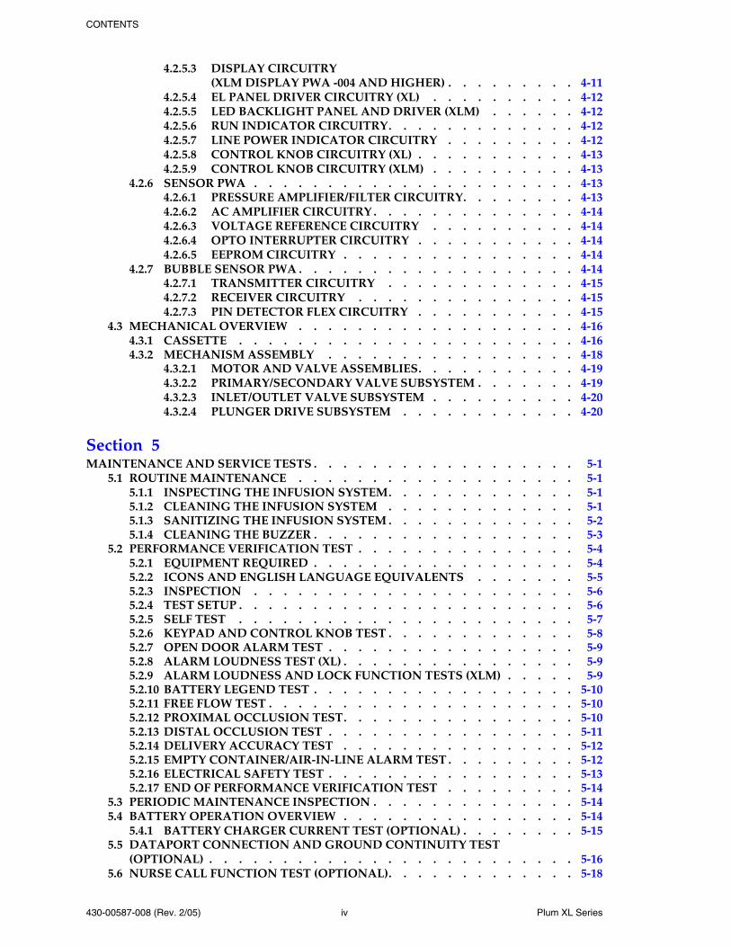
4.2.5.3 DISPLAY CIRCUITRY (XLM DISPLAY PWA -004 AND HIGHER) . . . . . . . . . 4-11
4.2.5.4 EL PANEL DRIVER CIRCUITRY (XL) . . . . . . . . . . 4-124.2.5.5 LED BACKLIGHT PANEL AND DRIVER (XLM) . . . . . . 4-124.2.5.6 RUN INDICATOR CIRCUITRY. . . . . . . . . . . . . 4-124.2.5.7 LINE POWER INDICATOR CIRCUITRY . . . . . . . . . 4-124.2.5.8 CONTROL KNOB CIRCUITRY (XL) . . . . . . . . . . . 4-134.2.5.9 CONTROL KNOB CIRCUITRY (XLM) . . . . . . . . . . 4-13
4.2.6 SENSOR PWA . . . . . . . . . . . . . . . . . . . . . . 4-134.2.6.1 PRESSURE AMPLIFIER/FILTER CIRCUITRY. . . . . . . . 4-134.2.6.2 AC AMPLIFIER CIRCUITRY . . . . . . . . . . . . . . 4-144.2.6.3 VOLTAGE REFERENCE CIRCUITRY . . . . . . . . . . 4-144.2.6.4 OPTO INTERRUPTER CIRCUITRY . . . . . . . . . . . 4-144.2.6.5 EEPROM CIRCUITRY . . . . . . . . . . . . . . . . 4-14
4.2.7 BUBBLE SENSOR PWA . . . . . . . . . . . . . . . . . . . 4-144.2.7.1 TRANSMITTER CIRCUITRY . . . . . . . . . . . . . 4-154.2.7.2 RECEIVER CIRCUITRY . . . . . . . . . . . . . . . 4-154.2.7.3 PIN DETECTOR FLEX CIRCUITRY . . . . . . . . . . . 4-15
4.3 MECHANICAL OVERVIEW . . . . . . . . . . . . . . . . . . . 4-164.3.1 CASSETTE . . . . . . . . . . . . . . . . . . . . . . . 4-164.3.2 MECHANISM ASSEMBLY . . . . . . . . . . . . . . . . . 4-18
4.3.2.1 MOTOR AND VALVE ASSEMBLIES. . . . . . . . . . . 4-194.3.2.2 PRIMARY/SECONDARY VALVE SUBSYSTEM . . . . . . . 4-194.3.2.3 INLET/OUTLET VALVE SUBSYSTEM . . . . . . . . . . 4-204.3.2.4 PLUNGER DRIVE SUBSYSTEM . . . . . . . . . . . . 4-20
Section 5MAINTENANCE AND SERVICE TESTS . . . . . . . . . . . . . . . . . . 5-1
5.1 ROUTINE MAINTENANCE . . . . . . . . . . . . . . . . . . . 5-15.1.1 INSPECTING THE INFUSION SYSTEM. . . . . . . . . . . . . 5-15.1.2 CLEANING THE INFUSION SYSTEM . . . . . . . . . . . . . 5-15.1.3 SANITIZING THE INFUSION SYSTEM . . . . . . . . . . . . . 5-25.1.4 CLEANING THE BUZZER . . . . . . . . . . . . . . . . . . 5-3
5.2 PERFORMANCE VERIFICATION TEST . . . . . . . . . . . . . . . 5-45.2.1 EQUIPMENT REQUIRED . . . . . . . . . . . . . . . . . . 5-45.2.2 ICONS AND ENGLISH LANGUAGE EQUIVALENTS . . . . . . . 5-55.2.3 INSPECTION . . . . . . . . . . . . . . . . . . . . . . 5-65.2.4 TEST SETUP . . . . . . . . . . . . . . . . . . . . . . . 5-65.2.5 SELF TEST . . . . . . . . . . . . . . . . . . . . . . . 5-75.2.6 KEYPAD AND CONTROL KNOB TEST . . . . . . . . . . . . . 5-85.2.7 OPEN DOOR ALARM TEST . . . . . . . . . . . . . . . . . 5-95.2.8 ALARM LOUDNESS TEST (XL) . . . . . . . . . . . . . . . . 5-95.2.9 ALARM LOUDNESS AND LOCK FUNCTION TESTS (XLM) . . . . . 5-95.2.10 BATTERY LEGEND TEST . . . . . . . . . . . . . . . . . . 5-105.2.11 FREE FLOW TEST . . . . . . . . . . . . . . . . . . . . . 5-105.2.12 PROXIMAL OCCLUSION TEST. . . . . . . . . . . . . . . . 5-105.2.13 DISTAL OCCLUSION TEST . . . . . . . . . . . . . . . . . 5-115.2.14 DELIVERY ACCURACY TEST . . . . . . . . . . . . . . . . 5-125.2.15 EMPTY CONTAINER/AIR-IN-LINE ALARM TEST . . . . . . . . . 5-125.2.16 ELECTRICAL SAFETY TEST . . . . . . . . . . . . . . . . . 5-135.2.17 END OF PERFORMANCE VERIFICATION TEST . . . . . . . . . 5-14
5.3 PERIODIC MAINTENANCE INSPECTION . . . . . . . . . . . . . . 5-145.4 BATTERY OPERATION OVERVIEW . . . . . . . . . . . . . . . . 5-14
5.4.1 BATTERY CHARGER CURRENT TEST (OPTIONAL) . . . . . . . . 5-155.5 DATAPORT CONNECTION AND GROUND CONTINUITY TEST
(OPTIONAL) . . . . . . . . . . . . . . . . . . . . . . . . . 5-165.6 NURSE CALL FUNCTION TEST (OPTIONAL). . . . . . . . . . . . . 5-18
CONTENTS
Technical Service Manual v 430-00587-008 (Rev. 2/05)
Section 6TROUBLESHOOTING . . . . . . . . . . . . . . . . . . . . . . . . 6-1
6.1 TECHNICAL ASSISTANCE. . . . . . . . . . . . . . . . . . . . 6-16.2 ALARM MESSAGES AND ERROR CODES . . . . . . . . . . . . . . 6-1
6.2.1 OPERATIONAL ALARM MESSAGES . . . . . . . . . . . . . 6-26.2.2 ERROR CODES REQUIRING TECHNICAL SERVICE . . . . . . . . 6-66.2.3 SERVICE MODE . . . . . . . . . . . . . . . . . . . . . 6-11
6.2.3.1 ALARM HISTORY . . . . . . . . . . . . . . . . . 6-116.2.3.2 SOFTWARE REVISION NUMBER . . . . . . . . . . . . 6-126.2.3.3 RUN TIME AND BATTERY RUN TIME . . . . . . . . . . 6-126.2.3.4 PARAMETER PROGRAMMING
(XLM WITH DATAPORT) . . . . . . . . . . . . . . . 6-126.3 TROUBLESHOOTING PROCEDURES. . . . . . . . . . . . . . . . 6-14
Section 7REPLACEABLE PARTS AND REPAIRS . . . . . . . . . . . . . . . . . . 7-1
7.1 REPLACEABLE PARTS . . . . . . . . . . . . . . . . . . . . . 7-17.2 REPLACEMENT PROCEDURES . . . . . . . . . . . . . . . . . . 7-3
7.2.1 SAFETY AND EQUIPMENT PRECAUTIONS . . . . . . . . . . . 7-37.2.2 REQUIRED TOOLS AND MATERIALS . . . . . . . . . . . . . 7-37.2.3 RUBBER FOOT PAD REPLACEMENT . . . . . . . . . . . . . 7-47.2.4 BATTERY WITH WIRE HARNESS ASSEMBLY, BATTERY DOOR, AND
BATTERY DOOR PAD REPLACEMENT . . . . . . . . . . . . . 7-67.2.5 SEPARATING THE FRONT ENCLOSURE ASSEMBLY, REAR ENCLOSURE
ASSEMBLY, AND MAIN CHASSIS ASSEMBLY . . . . . . . . . . 7-77.2.6 FRONT ENCLOSURE ASSEMBLY, REAR ENCLOSURE ASSEMBLY, OR
MAIN CHASSIS ASSEMBLY REPLACEMENT . . . . . . . . . . 7-97.2.7 FRONT ENCLOSURE ASSEMBLY COMPONENT REPLACEMENT . . . 7-10
7.2.7.1 DISPLAY PWA AND MCU/DISPLAY CABLE REPLACEMENT . . . . . . . . . . . . . . . . . . 7-11
7.2.7.2 FRONT PANEL KEY REPLACEMENT . . . . . . . . . . 7-127.2.7.3 CONTROL KNOB, KNOB DETENT, WASHER, GASKET, SNAP
RETAINER, AND DETENT RING REPLACEMENT . . . . . 7-137.2.7.4 FRONT PANEL LABEL REPLACEMENT . . . . . . . . . 7-14
7.2.8 REAR ENCLOSURE ASSEMBLY COMPONENT REPLACEMENT . . . 7-147.2.8.1 FUSE REPLACEMENT . . . . . . . . . . . . . . . . 7-157.2.8.2 POWER SUPPLY PWA REPLACEMENT . . . . . . . . . . 7-177.2.8.3 VELCRO RETAINER STRAP REPLACEMENT . . . . . . . 7-197.2.8.4 AC (MAINS) POWER CORD AND STRAIN RELIEF BUSHING
REPLACEMENT . . . . . . . . . . . . . . . . . . 7-197.2.8.5 AC (MAINS) POWER CORD REPLACEMENT
(INTERNATIONAL) . . . . . . . . . . . . . . . . . 7-217.2.8.6 AC RECEPTACLE, EMI SHIELD, AND EQUIPOTENTIAL POST
REPLACEMENT . . . . . . . . . . . . . . . . . . 7-227.2.8.7 LIFECARE AC RECEPTACLE, BRACKET, GASKET, SEAL, AND
EQUIPOTENTIAL POST REPLACEMENT . . . . . . . . . 7-237.2.8.8 DATAPORT/MCU CABLE ASSEMBLY REPLACEMENT
(XLM WITH DATAPORT) . . . . . . . . . . . . . . . 7-257.2.8.9 LIFECARE DATAPORT/MCU CABLE ASSEMBLY REPLACEMENT
(XLM WITH DATAPORT) . . . . . . . . . . . . . . . 7-277.2.8.10 POLE CLAMP EXTRUSION, POLE CLAMP BACKING PLATE,
AND ADHESIVE-BACKED INSULATOR REPLACEMENT . . . 7-287.2.8.11 POLE CLAMP SHAFT/KNOB ASSEMBLY AND POLE CLAMP
SHAFT TIP REPLACEMENT . . . . . . . . . . . . . . 7-307.2.8.12 BUZZER PWA AND MCU/BUZZER CABLE
REPLACEMENT . . . . . . . . . . . . . . . . . . 7-31
CONTENTS
430-00587-008 (Rev. 2/05) vi Plum XL Series
7.2.9 MAIN CHASSIS ASSEMBLY COMPONENT REPLACEMENT . . . . 7-327.2.9.1 MCU PWA AND SENSOR/MCU CABLE ASSEMBLY
REPLACEMENT . . . . . . . . . . . . . . . . . . 7-337.2.9.2 MECHANISM ASSEMBLY REPLACEMENT . . . . . . . . 7-357.2.9.3 CASSETTE DOOR AND MECHANISM SHIELD
REPLACEMENT . . . . . . . . . . . . . . . . . . 7-367.2.9.4 OPENER HANDLE ASSEMBLY REPLACEMENT . . . . . . 7-41
Section 8SPECIFICATIONS . . . . . . . . . . . . . . . . . . . . . . . . . . 8-1
8.1 PLUM XL AND XLM . . . . . . . . . . . . . . . . . . . . . . 8-18.2 LIFECARE XL AND XLM . . . . . . . . . . . . . . . . . . . . 8-2
Section 9DRAWINGS . . . . . . . . . . . . . . . . . . . . . . . . . . . . 9-1
Appendix . . . . . . . . . . . . . . . . . . . . . . . . . . . . . . . . . . . A-1
Index. . . . . . . . . . . . . . . . . . . . . . . . . . . . . . . . . . . . . . I-1

FIGURES
Technical Service Manual vii 430-00587-008 (Rev. 2/05)
Figures
Figure 1-1. Plum XL Icon Based and English Language Front Panels . . . . . . . . 1-4Figure 1-2. Plum XLM Icon Based and English Language Front Panels . . . . . . . 1-4Figure 1-3. Plum XL LCD Test Screens . . . . . . . . . . . . . . . . . . 1-10Figure 1-4. Plum XLM LCD Test Screens. . . . . . . . . . . . . . . . . . 1-10Figure 4-1. Major Elements of the Dual-Channel Cassette. . . . . . . . . . . . 4-17Figure 4-2. Fluid Path in the Cassette . . . . . . . . . . . . . . . . . . . 4-18Figure 4-3. Mechanism Valve Pins and Sensor Locations . . . . . . . . . . . . 4-20Figure 5-1. Cleaning the Buzzer . . . . . . . . . . . . . . . . . . . . . 5-3Figure 5-2. Icons and English Language Equivalents . . . . . . . . . . . . . 5-5Figure 5-3. Plum XL LCD Test Screens . . . . . . . . . . . . . . . . . . 5-7Figure 5-4. Plum XLM LCD Test Screens. . . . . . . . . . . . . . . . . . 5-8Figure 5-5. Distal Occlusion Test Setup . . . . . . . . . . . . . . . . . . 5-11Figure 5-6. Special Cassettes with Bubble Sensor Tips Removed . . . . . . . . . 5-13Figure 5-7. Battery Charger Current Test Configuration . . . . . . . . . . . . 5-16Figure 5-8. DataPort Connector . . . . . . . . . . . . . . . . . . . . . 5-17Figure 7-1. Bottom View of the Infusion System . . . . . . . . . . . . . . . 7-5Figure 7-2. Front Enclosure, Main Chassis Assembly, and Rear Enclosure . . . . . . 7-8Figure 7-3. Display PWA and MCU/Display Cable . . . . . . . . . . . . . . 7-10Figure 7-4. Front Enclosure Assembly Components . . . . . . . . . . . . . . 7-11Figure 7-5. Fuse Replacement (115 VAC) . . . . . . . . . . . . . . . . . . 7-16Figure 7-6. Fuse Replacement (220 VAC) . . . . . . . . . . . . . . . . . . 7-16Figure 7-7. Power Supply PWA . . . . . . . . . . . . . . . . . . . . . 7-18Figure 7-8. AC Power Cord (115 VAC - Plum XL) . . . . . . . . . . . . . . . 7-20Figure 7-9. AC Power Cord (115 VAC - Plum XLM) . . . . . . . . . . . . . . 7-21Figure 7-10. AC Power Cord (220 VAC - Plum XLM) . . . . . . . . . . . . . . 7-23Figure 7-11. AC Power Cord (220 VAC - Plum XLM) . . . . . . . . . . . . . . 7-24Figure 7-12. DataPort Assembly (Domestic) . . . . . . . . . . . . . . . . . 7-26Figure 7-13. DataPort Assembly (International) . . . . . . . . . . . . . . . . 7-28Figure 7-14. XL Series Pole Clamp . . . . . . . . . . . . . . . . . . . . 7-30Figure 7-15. Buzzer PWA . . . . . . . . . . . . . . . . . . . . . . . . 7-32Figure 7-16. Exploded View of the Main Chassis Assembly . . . . . . . . . . . 7-34Figure 7-17. Top View of the Main Chassis Assembly . . . . . . . . . . . . . 7-35Figure 7-18. Mechanism Shield Replacement . . . . . . . . . . . . . . . . 7-38Figure 7-19. Cassette Door Replacement (1 of 3). . . . . . . . . . . . . . . . 7-39Figure 7-20. Cassette Door Replacement (2 of 3). . . . . . . . . . . . . . . . 7-39Figure 7-21. Cassette Door Replacement (3 of 3) . . . . . . . . . . . . . . . 7-40Figure 7-22. Cassette Door Replacement, Bottom View . . . . . . . . . . . . . 7-40Figure 7-23. Opener Handle Assembly Replacement (1 of 3) . . . . . . . . . . . 7-42Figure 7-24. Opener Handle Assembly Replacement (2 of 3) . . . . . . . . . . . 7-43Figure 7-25. Opener Handle Assembly Replacement (3 of 3) . . . . . . . . . . . 7-43Figure 9-1. Illustrated Parts Breakdown . . . . . . . . . . . . . . . . . . 9-7Figure 9-2. Front Enclosure, Rear Enclosure, and Main Chassis Assemblies . . . . . 9-11Figure 9-3. Front Enclosure Assembly . . . . . . . . . . . . . . . . . . . 9-13Figure 9-4. Rear Enclosure Assembly (XL Domestic) . . . . . . . . . . . . . . 9-15Figure 9-5. Rear Enclosure Assembly (XL International) . . . . . . . . . . . . 9-17Figure 9-6. Rear Enclosure Assembly (XLM Domestic) . . . . . . . . . . . . . 9-19Figure 9-7. Rear Enclosure Assembly (XLM International) . . . . . . . . . . . 9-21Figure 9-8. Rear Enclosure Assembly (XLM with DataPort - Domestic) . . . . . . . 9-23Figure 9-9. Rear Enclosure Assembly (XLM with DataPort - International ) . . . . . 9-25Figure 9-10. Rear Enclosure Assembly (Lifecare XLM with DataPort) . . . . . . . . 9-27Figure 9-11. Main Chassis Assembly. . . . . . . . . . . . . . . . . . . . 9-29Figure 9-12. Battery Replacement . . . . . . . . . . . . . . . . . . . . . 9-31Figure 9-13. Mechanical Assembly . . . . . . . . . . . . . . . . . . . . 9-33
FIGURES
430-00587-008 (Rev. 2/05) viii Plum XL Series
Figure 9-14. Plum XL Block Diagram . . . . . . . . . . . . . . . . . . . 9-37Figure 9-15. MCU PWA Schematic (XL) . . . . . . . . . . . . . . . . . . 9-39Figure 9-16. MCU PWA Schematic (XLM) . . . . . . . . . . . . . . . . . . 9-43Figure 9-17. MCU PWA Schematic (XLM with DataPort) . . . . . . . . . . . . 9-47Figure 9-18. Display PWA Schematic (XL). . . . . . . . . . . . . . . . . . 9-83Figure 9-19. Display PWA Schematic (XLM) . . . . . . . . . . . . . . . . . 9-85Figure 9-20. Bubble Sensor PWA Schematic . . . . . . . . . . . . . . . . . 9-99Figure 9-21. Sensor PWA Schematic . . . . . . . . . . . . . . . . . . . . 9-105Figure 9-22. Pin Detector Flex Circuit Schematic . . . . . . . . . . . . . . . 9-107Figure 9-23. Power Supply PWA Schematic (XL Domestic) . . . . . . . . . . . . 9-109Figure 9-24. Power Supply PWA Schematic (XL International) . . . . . . . . . . 9-113Figure 9-25. Power Supply PWA Schematic (XLM Domestic) . . . . . . . . . . . 9-117Figure 9-26. Power Supply PWA Schematic (XLM International) . . . . . . . . . 9-121Figure 9-27. Power Supply PWA Schematic (XLM with DataPort) . . . . . . . . . 9-129Figure 9-28. Buzzer PWA Schematic . . . . . . . . . . . . . . . . . . . . 9-137
Tables
Table 1-1. Global Product Configurations . . . . . . . . . . . . . . . . . 1-2Table 1-2. Conventions . . . . . . . . . . . . . . . . . . . . . . . . 1-5Table 4-1. Battery Charge Current States . . . . . . . . . . . . . . . . . 4-4Table 5-1. Cleaning Solutions . . . . . . . . . . . . . . . . . . . . . 5-2Table 5-2. Battery Charger Current Test Parameters . . . . . . . . . . . . . 5-16Table 6-1. Operational Alarm Messages and Corrective Actions . . . . . . . . . 6-2Table 6-2. Error Codes Requiring Technical Service . . . . . . . . . . . . . 6-6Table 6-3. Service Mode Control Knob Settings . . . . . . . . . . . . . . . 6-11Table 6-4. Sub-Modes of Parameter Programming . . . . . . . . . . . . . . 6-12Table 6-5. Communication Circuitry Selections . . . . . . . . . . . . . . . 6-13Table 6-6. PVT Troubleshooting . . . . . . . . . . . . . . . . . . . . 6-14Table 7-1. Wire Color Coding . . . . . . . . . . . . . . . . . . . . . 7-18Table 9-1. Drawings . . . . . . . . . . . . . . . . . . . . . . . . . 9-1Table 9-2. IPB for the Infusion System . . . . . . . . . . . . . . . . . . 9-2Table A-1. Guidance and Manufacturer’s Declaration - Electromagnetic Emissions . . A-1Table A-2. Guidance and Manufacturer’s Declaration - Electromagnetic Immunity . . A-2Table A-3. Guidance and Manufacturer’s Declaration - Electromagnetic Immunity for
Life-Supporting Equipment and Systems . . . . . . . . . . . . . A-3Table A-4. Recommended Separation Distances Between Portable and Mobile RF
Communications Equipment and the LifeCare XLM with DataPort . . . . A-5
Technical Service Manual 1 - 1 430-00587-008 (Rev. 2/05)
Section 1
INTRODUCTION
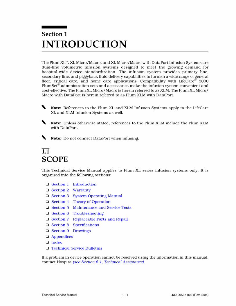
The Plum XL™, XL Micro/Macro, and XL Micro/Macro with DataPort Infusion Systems aredual-line volumetric infusion systems designed to meet the growing demand forhospital-wide device standardization. The infusion system provides primary line,secondary line, and piggyback fluid delivery capabilities to furnish a wide range of generalfloor, critical care, and home care applications. Compatibility with LifeCare® 5000PlumSet® administration sets and accessories make the infusion system convenient andcost-effective. The Plum XL Micro/Macro is herein referred to as XLM. The Plum XL Micro/Macro with DataPort is herein referred to as Plum XLM with DataPort.
Note: References to the Plum XL and XLM Infusion Systems apply to the LifeCareXL and XLM Infusion Systems as well.
Note: Unless otherwise stated, references to the Plum XLM include the Plum XLMwith DataPort.
Note: Do not connect DataPort when infusing.
1.1SCOPEThis Technical Service Manual applies to Plum XL series infusion systems only. It isorganized into the following sections:
Section 1 Introduction
Section 2 Warranty
Section 3 System Operating Manual
Section 4 Theory of Operation
Section 5 Maintenance and Service Tests
Section 6 Troubleshooting
Section 7 Replaceable Parts and Repair
Section 8 Specifications
Section 9 Drawings
Appendices
Index
Technical Service Bulletins
If a problem in device operation cannot be resolved using the information in this manual,contact Hospira (see Section 6.1, Technical Assistance).
SECTION 1 INTRODUCTION
430-00587-008 (Rev. 2/05) 1 - 2 Plum XL Series
Specific instructions for operating the device are contained in the Plum XL SystemOperating Manual, Plum XL Micro/Macro System Operating Manual, and Plum XL Micro/Macro with DataPort System Operating Manual. Provision is made for the inclusion of thesystem operating manual in Section 3 of this manual.
Note: In this manual, the terms “device” and “infusion system” refer to allconfigurations of the Plum XL series infusion system unless otherwise specified.Display messages and key labels may vary slightly, depending on the configurationof the infusion system in use.
Note: Figures are rendered as graphic representations to approximate actualproduct; therefore, figures may not exactly reflect the product.
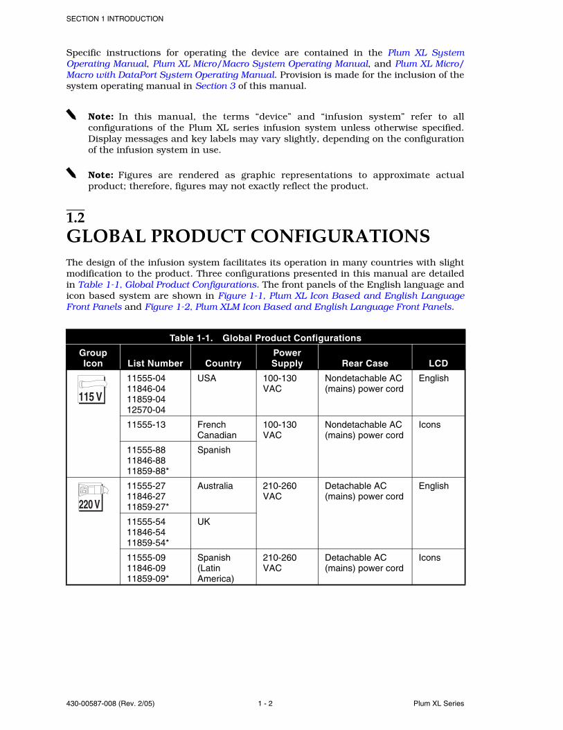
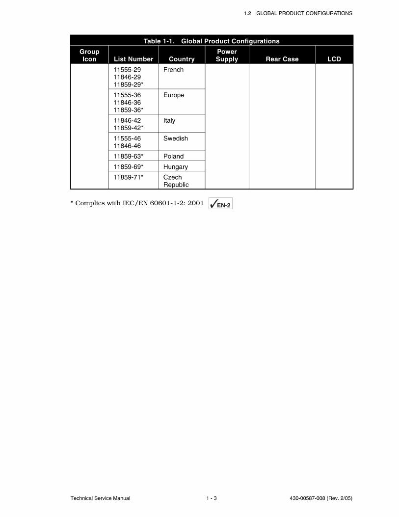
1.2GLOBAL PRODUCT CONFIGURATIONSThe design of the infusion system facilitates its operation in many countries with slightmodification to the product. Three configurations presented in this manual are detailedin Table 1-1, Global Product Configurations. The front panels of the English language andicon based system are shown in Figure 1-1, Plum XL Icon Based and English LanguageFront Panels and Figure 1-2, Plum XLM Icon Based and English Language Front Panels.
Table 1-1. Global Product Configurations
GroupIcon List Number Country
Power Supply Rear Case LCD
11555-04 11846-04 11859-04 12570-04
USA 100-130 VAC
Nondetachable AC (mains) power cord
English
11555-13 French Canadian
100-130 VAC
Nondetachable AC (mains) power cord
Icons
11555-88 11846-88 11859-88*
Spanish
11555-27 11846-27 11859-27*
Australia 210-260 VAC
Detachable AC (mains) power cord
English
11555-54 11846-54 11859-54*
UK
11555-09 11846-09 11859-09*
Spanish (Latin America)
210-260 VAC
Detachable AC (mains) power cord
Icons
115 V
220 V
1.2 GLOBAL PRODUCT CONFIGURATIONS
Technical Service Manual 1 - 3 430-00587-008 (Rev. 2/05)
* Complies with IEC/EN 60601-1-2: 2001
11555-29 11846-29 11859-29*
French
11555-36 11846-36 11859-36*
Europe
11846-42 11859-42*
Italy
11555-46 11846-46
Swedish
11859-63* Poland
11859-69* Hungary
11859-71* Czech Republic
Table 1-1. Global Product Configurations
GroupIcon List Number Country
Power Supply Rear Case LCD
EN-2

SECTION 1 INTRODUCTION
430-00587-008 (Rev. 2/05) 1 - 4 Plum XL Series
Figure 1-1. Plum XL Icon Based and English Language Front Panels
Figure 1-2. Plum XLM Icon Based and English Language Front Panels
PRISEC
TITRATE
SET RATE
SET VTBIRUN
HOLD/RESET
CLEARVOL
OFFCHARGE
SILENCE
0000 mL
mL
mL / H
ICON BASED ENGLISH LANGUAGE
04K01021
BACK
PRIME
mL
mL/H 0000 mL SET RATE
SET VTBI
RUN
HOLD/RESET
CLEAR
VOL
QUICKSET
TITRATE
PRI
BACK
PRIME
SEC
SILENCE
OFF
CHARGE
1 2
04K01022
ICON BASED ENGLISH LANGUAGE
1.3 CONVENTIONS
Technical Service Manual 1 - 5 430-00587-008 (Rev. 2/05)
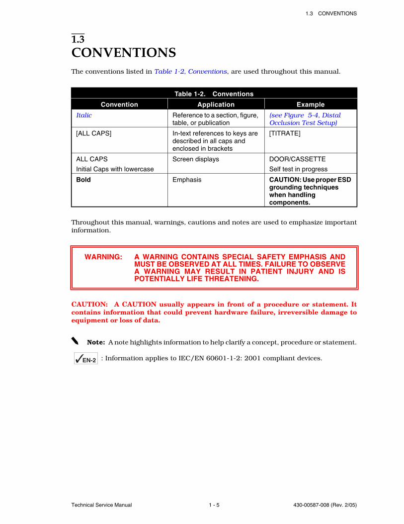
1.3CONVENTIONSThe conventions listed in Table 1-2, Conventions, are used throughout this manual.
Throughout this manual, warnings, cautions and notes are used to emphasize importantinformation.
CAUTION: A CAUTION usually appears in front of a procedure or statement. Itcontains information that could prevent hardware failure, irreversible damage toequipment or loss of data.
Note: A note highlights information to help clarify a concept, procedure or statement.
: Information applies to IEC/EN 60601-1-2: 2001 compliant devices.
Table 1-2. Conventions
Convention Application Example
Italic Reference to a section, figure, table, or publication
(see Figure 5-4, Distal Occlusion Test Setup)
[ALL CAPS] In-text references to keys are described in all caps and enclosed in brackets
[TITRATE]
ALL CAPS
Initial Caps with lowercase
Screen displays DOOR/CASSETTE
Self test in progress
Bold Emphasis CAUTION: Use proper ESD grounding techniques when handling components.
WARNING: A WARNING CONTAINS SPECIAL SAFETY EMPHASIS ANDMUST BE OBSERVED AT ALL TIMES. FAILURE TO OBSERVEA WARNING MAY RESULT IN PATIENT INJURY AND ISPOTENTIALLY LIFE THREATENING.
EN-2
SECTION 1 INTRODUCTION
430-00587-008 (Rev. 2/05) 1 - 6 Plum XL Series
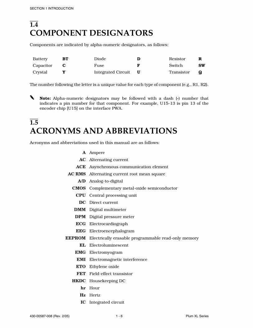
1.4COMPONENT DESIGNATORSComponents are indicated by alpha-numeric designators, as follows:
The number following the letter is a unique value for each type of component (e.g., R1, R2).
Note: Alpha-numeric designators may be followed with a dash (-) number thatindicates a pin number for that component. For example, U15-13 is pin 13 of theencoder chip [U15] on the interface PWA.
1.5ACRONYMS AND ABBREVIATIONSAcronyms and abbreviations used in this manual are as follows:
A Ampere
AC Alternating current
ACE Asynchronous communication element
AC RMS Alternating current root mean square
A/D Analog-to-digital
CMOS Complementary metal-oxide semiconductor
CPU Central processing unit
DC Direct current
DMM Digital multimeter
DPM Digital pressure meter
ECG Electrocardiograph
EEG Electroencephalogram
EEPROM Electrically erasable programmable read-only memory
EL Electroluminescent
EMG Electromyogram
EMI Electromagnetic interference
ETO Ethylene oxide
FET Field-effect transistor
HKDC Housekeeping DC
hr Hour
Hz Hertz
IC Integrated circuit
Battery BT Diode D Resistor R
Capacitor C Fuse F Switch SW
Crystal Y Integrated Circuit U Transistor Q

1.6 USER QUALIFICATION
Technical Service Manual 1 - 7 430-00587-008 (Rev. 2/05)
IEC International Electrotechnical Commission
IPB Illustrated parts breakdown
IV Intravenous
kHz Kilohertz
KVO Keep vein open
LCD Liquid crystal display
LED Light-emitting diode
mA Milliampere
MCU Micro controller unit
MHz Megahertz
mL Milliliter
mV Millivolt
PLL Phase-lock loop
PVT Performance verification test
PSI Pounds per square inch
PWA Printed wiring assembly
SPSTIN Single-pole, single-throw in
UART Universal asynchronous receiver/transmitter
VAC Volts AC
VCO Voltage-controlled oscillator
VCC Collector supply voltage
VDC Volts DC
VDIG Digital voltage
VMOT Motor voltage
Vpp Volts peak-to-peak
VTBI Volume to be infused
µA Microampere
µL microliter
µS microsecond
1.6USER QUALIFICATIONThe Plum XL series infusion system is for use at the direction or under the supervision oflicensed physicians or certified healthcare professionals who are trained in the use of theinfusion system and the administration of parenteral and enteral fluids and drugs, andwhole blood or red blood cell components. Training should emphasize preventing relatedIV complications, including appropriate precautions to prevent accidental infusion of air.The epidural route can be used to provide anesthesia or analgesia.
SECTION 1 INTRODUCTION
430-00587-008 (Rev. 2/05) 1 - 8 Plum XL Series
1.7ARTIFACTSNonhazardous, low-level electrical potentials are commonly observed when fluids areadministered using infusion devices. These potentials are well within accepted safetystandards, but may create artifacts on voltage-sensing equipment such as ECG, EMG,and EEG machines. These artifacts vary at a rate that is associated with the infusion rate.If the monitoring machine is not operating correctly or has loose or defective connectionsto its sensing electrodes, these artifacts may be accentuated so as to simulate actualphysiological signals. To determine if the abnormality in the monitoring equipment iscaused by the infuser instead of some other source in the environment, set the infuser sothat it is temporarily not delivering fluid. Disappearance of the abnormality indicates thatit was probably caused by electronic noise generated by the infuser. Proper setup andmaintenance of the monitoring equipment should eliminate the artifact. Refer to theappropriate monitoring system documentation for setup and maintenance instructions.
1.8INSTRUMENT INSTALLATION PROCEDURECAUTION: Infusion system damage may occur unless proper care is exercisedduring product unpacking and installation. The battery may not be fully chargedupon receipt of the infusion system. Do not place the infusion system in service if itfails the self test.
CAUTION: Infusion system performance may be degraded by electromagneticinterference (EMI) from devices such as electrosurgical units, cellular phones, andtwo-way radios. Operation of the infusion system under such conditions should beavoided.
CAUTION: Before operating the infusion system next to, or in a stackedconfiguration with other electrical equipment, confirm the infusion system’soperational performance in that configuration.
CAUTION: The use of any accessory, transducer or cable with the LifeCare XLMwith DataPort other than those specified may result in increased emissions ordecreased immunity of the LifeCare XLM with DataPort.
The instrument installation procedure consists of unpacking, inspecting, and self test.
Note: Do not place the infusion system in service if the battery is not fully charged.To make certain the battery is fully charged, connect the infusion system to AC(mains) power for eight hours (see Section 8, Specifications).
1.8.1UNPACKING
Inspect the infusion system shipping container as detailed in Section 1.8.2, Inspection.Use care when unpacking the infusion system. Retain the packing slip and save all packingmaterials in the event it is necessary to return the infusion system to the factory. Verifythat the shipping container includes a copy of the system operating manual.
1.8 INSTRUMENT INSTALLATION PROCEDURE
Technical Service Manual 1 - 9 430-00587-008 (Rev. 2/05)
1.8.2INSPECTION
Inspect the infusion system for shipping damage. Should any damage be found, contactthe delivering carrier immediately.
CAUTION: Do not use the infusion system if it appears to be damaged. Shoulddamage be found, contact Hospira (see Section 6.1, Technical Assistance). Do not usethe infusion system if it appears to be damaged.
Inspect the infusion system periodically for signs of defects such as worn accessories,broken connections, or damaged cable assemblies. Also inspect the infusion system afterrepair or during cleaning. Replace any damaged or defective external parts.
1.8.3SELF TEST
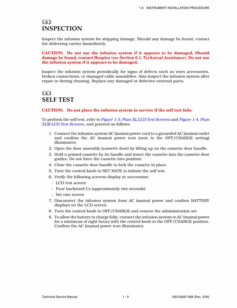
CAUTION: Do not place the infusion system in service if the self test fails.
To perform the self test, refer to Figure 1-3, Plum XL LCD Test Screens and Figure 1-4, PlumXLM LCD Test Screens, and proceed as follows:
1. Connect the infusion system AC (mains) power cord to a grounded AC (mains) outletand confirm the AC (mains) power icon (next to the OFF/CHARGE setting)illuminates.
2. Open the door assembly (cassette door) by lifting up on the cassette door handle.
3. Hold a primed cassette by its handle and insert the cassette into the cassette doorguides. Do not force the cassette into position.
4. Close the cassette door handle to lock the cassette in place.
5. Turn the control knob to SET RATE to initiate the self test.
6. Verify the following screens display in succession:
- LCD test screen
- Four backward Cs (approximately two seconds)
- Set rate screen
7. Disconnect the infusion system from AC (mains) power and confirm BATTERYdisplays on the LCD screen.
8. Turn the control knob to OFF/CHARGE and remove the administration set.
9. To allow the battery to charge fully, connect the infusion system to AC (mains) powerfor a minimum of eight hours with the control knob in the OFF/CHARGE position.Confirm the AC (mains) power icon illuminates.
SECTION 1 INTRODUCTION
430-00587-008 (Rev. 2/05) 1 - 10 Plum XL Series
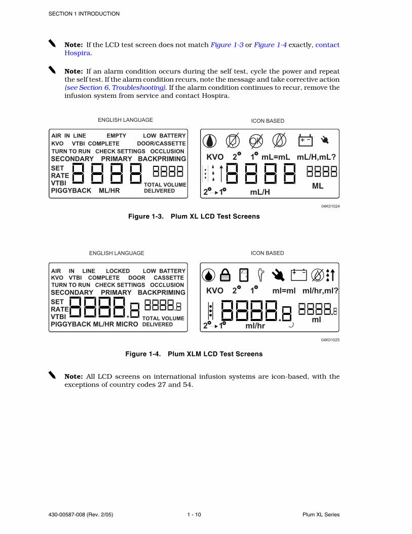
Note: If the LCD test screen does not match Figure 1-3 or Figure 1-4 exactly, contactHospira.
Note: If an alarm condition occurs during the self test, cycle the power and repeatthe self test. If the alarm condition recurs, note the message and take corrective action(see Section 6, Troubleshooting). If the alarm condition continues to recur, remove theinfusion system from service and contact Hospira.
Figure 1-3. Plum XL LCD Test Screens
Figure 1-4. Plum XLM LCD Test Screens
Note: All LCD screens on international infusion systems are icon-based, with theexceptions of country codes 27 and 54.
KVO 2 1 mL=mL mL/H,mL?
04K01024
2 1 mL/HML
AIR IN LINE EMPTY LOW BATTERY
KVO VTBI COMPLETE DOOR/CASSETTE
TURN TO RUN CHECK SETTINGS OCCLUSION
SECONDARY PRIMARY BACKPRIMING
SET
RATE
VTBI
PIGGYBACK ML/HR TOTAL VOLUME
DELIVERED
OK
KVO 2 1 mL=mL mL/H,mL?
04K01024
ENGLISH LANGUAGE
2 1 mL/HML
AIR IN LINE EMPTY LOW BATTERY
KVO VTBI COMPLETE DOOR/CASSETTE
TURN TO RUN CHECK SETTINGS OCCLUSION
SECONDARY PRIMARY BACKPRIMING
SET
RATE
VTBI
PIGGYBACK ML/HR TOTAL VOLUME
DELIVERED
OK
ICON BASED
KVO 2 1 ml=ml ml/hr,ml?
04K01025
ENGLISH LANGUAGE
2 1 ml/hr ml
AIR IN LINE LOCKED LOW BATTERY
KVO VTBI COMPLETE DOOR CASSETTE
TURN TO RUN CHECK SETTINGS OCCLUSION
SECONDARY PRIMARY BACKPRIMING
SET
RATE
VTBI
PIGGYBACK ML/HR MICROTOTAL VOLUME
DELIVERED
ICON BASED

Technical Service Manual 2 - 1 430-00587-008 (Rev. 2/05)
Section 2
WARRANTY
Subject to the terms and conditions herein, Hospira, Inc., herein referred to as Hospira,warrants that (a) the product shall conform to Hospira’s standard specifications and befree from defects in material and workmanship under normal use and service for a periodof one year after purchase, and (b) the replaceable battery shall be free from defects inmaterial and workmanship under normal use and service for a period of 90 days afterpurchase. Hospira makes no other warranties, express or implied, as to merchantability,fitness for a particular purpose, or any other matter.
Purchaser's exclusive remedy shall be, at Hospira's option, the repair or replacement ofthe product. In no event shall Hospira's liability arising out of any cause whatsoever(whether such cause be based in contract, negligence, strict liability, other tort, orotherwise) exceed the price of such product, and in no event shall Hospira be liable forincidental, consequential, or special damages or losses or for lost business, revenues, orprofits. Warranty product returned to Hospira must be properly packaged and sent freightprepaid.
The foregoing warranty shall be void in the event the product has been misused, damaged,altered, or used other than in accordance with product manuals so as, in Hospira'sjudgment, to affect its stability or reliability, or in the event the serial or lot number hasbeen altered, effaced, or removed.
The foregoing warranty shall also be void in the event any person, including the Purchaser,performs or attempts to perform any major repair or other service on the product withouthaving been trained by an authorized representative of Hospira and using Hospiradocumentation and approved spare parts. For purposes of the preceding sentence, “majorrepair or other service” means any repair or service other than the replacement of accessoryitems such as batteries, flow detectors, detachable AC power cords, and patient pendants.
In providing any parts for repair or service of the product, Hospira shall have noresponsibility or liability for the actions or inactions of the person performing such repairor service, regardless of whether such person has been trained to perform such repair orservice. It is understood and acknowledged that any person other than a Hospirarepresentative performing repair or service is not an authorized agent of Hospira.

SECTION 2 WARRANTY
430-00587-008 (Rev. 2/05) 2 - 2 Plum XL Series
This page intentionally left blank.

Technical Service Manual 3 - 1 430-00587-008 (Rev. 2/05)
Section 3
SYSTEM OPERATING MANUAL
A copy of the system operating manual is included with every infusion system. Insert acopy here for convenient reference. If a copy of the system operating manual is notavailable, contact Hospira Technical Support Operations (see Section 6.1, TechnicalAssistance).

SECTION 3 SYSTEM OPERATING MANUAL
430-00587-008 (Rev. 2/05) 3 - 2 Plum XL Series
This page intentionally left blank.
Technical Service Manual 4 - 1 430-00587-008 (Rev. 2/05)
Section 4
THEORY OF OPERATION
This section describes the infusion system theory of operation. Related drawings areprovided in Section 9, Drawings. The theory of operation details the infusion systemgeneral description, electronics overview for both 115 VAC and 220 VAC systems, andmechanical overview of the system.
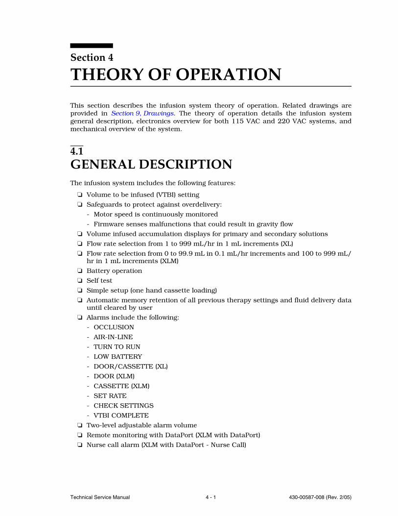
4.1GENERAL DESCRIPTIONThe infusion system includes the following features:
Volume to be infused (VTBI) setting
Safeguards to protect against overdelivery:
- Motor speed is continuously monitored
- Firmware senses malfunctions that could result in gravity flow
Volume infused accumulation displays for primary and secondary solutions
Flow rate selection from 1 to 999 mL/hr in 1 mL increments (XL)
Flow rate selection from 0 to 99.9 mL in 0.1 mL/hr increments and 100 to 999 mL/hr in 1 mL increments (XLM)
Battery operation
Self test
Simple setup (one hand cassette loading)
Automatic memory retention of all previous therapy settings and fluid delivery datauntil cleared by user
Alarms include the following:
- OCCLUSION
- AIR-IN-LINE
- TURN TO RUN
- LOW BATTERY
- DOOR/CASSETTE (XL)
- DOOR (XLM)
- CASSETTE (XLM)
- SET RATE
- CHECK SETTINGS
- VTBI COMPLETE
Two-level adjustable alarm volume
Remote monitoring with DataPort (XLM with DataPort)
Nurse call alarm (XLM with DataPort - Nurse Call)
SECTION 4 THEORY OF OPERATION
430-00587-008 (Rev. 2/05) 4 - 2 Plum XL Series
Note: Do not connect DataPort when infusing.
Note: Nurse call alarm is not available in IEC compliant infuser.
4.2ELECTRONICS OVERVIEWThis section describes the function and electronic circuitry of each printed wiring assembly(PWA) in the infusion system:
Power supply PWA
Micro controller unit (MCU) PWA
Display PWA
Buzzer PWA
Sensor PWA
Bubble sensor PWA
Schematic diagrams supporting the operation of infusion system PWAs are inSection 9, Drawings.
4.2.1POWER SUPPLY PWA
The power supply PWA provides direct current (DC) power to system circuits andcharges the battery (see Figure 9-23, Power Supply PWA Schematic (XL Domestic),Figure 9-25, Power Supply PWA Schematic (XLM Domestic) or Figure 9-27, PowerSupply PWA Schematic (XLM with DataPort)). The power supply PWA consists of
switcher circuitry, voltage regulator circuitry, and battery charger circuitry. The followingsections describe these circuits.
4.2.1.1SWITCHER CIRCUITRY
The primary function of the switcher circuitry is to convert alternating currentAC (mains) line power to an isolated +11 volts DC (VDC). Fuses F1 and F2, andvariable resistor VR1 provide protection against AC (mains) line-high voltagespikes and excessive input power demands. Capacitors C1 and C2, transformer
T1, and inductor L1 attenuate the conducted emissions. Bridge rectifier U1, resistor R1,and capacitor C3 provide the DC voltage required for switcher circuit. Diodes CR1 andCR2, R2, R3, CR4, C4, and C9 provide the supply voltage to the current mode-switchercontroller integrated circuit (IC) U2. Transistor Q1, transformer T2, IC U2, and theassociated passive components are enclosed in a shielded box to minimize radiatedelectromagnetic interference (EMI). U2 controls the duty cycle of Q1 through resistors R5and R6. Resistor R9 provides current sensing. Resistor R8 and capacitor C7 filter the rampvoltage across R9 and feed it back to U2.
EN-2
115 V
115 V
4.2 ELECTRONICS OVERVIEW
Technical Service Manual 4 - 3 430-00587-008 (Rev. 2/05)
U2 configuration allows DC voltage at pin 9 (ERR+) to equal the peak voltage across resistorR9. DC voltage controls the delivered power through transformer T2 to regulate the outputvoltage. Voltage at U2-9 is limited to +1.25 VDC so that peak current through transistorQ1 is limited to approximately 2 amperes (A). This limit constitutes the output shortprotection.
Optocoupler U3 is part of the main regulation loop; it provides the UL-544 isolation barrier.
Resistor R61, diode CR5, and capacitor C6 provide protection from T2 windings short byapplying the higher voltage across resistor R9 to the U2 inhibit input. C6 and the inputimpedance at U2-4 determine the low hiccup frequency in the event of a T2 winding short.
Diode CR3 and the clamp winding of transformer T2 provide intermediate energy transferto capacitor C3 and limit the peak voltage across transistor Q1. At AC (mains) power-up,capacitor C12 provides delayed timing to permit the voltage potential at U2-14 (Vcc) toreach its minimum level.
Diode CR11 and capacitors C23 and C24 rectify the transformer T2 voltage to create themain DC voltage source (+BUSS) for the infusion system. Diode CR10, resistor R23, ICU4, and capacitor C19 constitute a secondary +12 VDC control loop for protection in caseof primary loop failure. Diode CR12 and capacitor C25 create a feed-forward convertednegative voltage across capacitor C25 to switch transistor Q9 on through resistor R57 anddiode CR14. The Q9 output, housekeeping DC (HKDC), provides the necessary voltage topower both the main regulation loop and the charger circuitry. HKDC is at ground potentialwhen AC (mains) is off and CR12 blocks unnecessary battery power drain. Resistors R58,R59, and R60; capacitors C30, C31, and C32; and IC U9 filter HKDC and create a stable+2.5 VDC reference voltage (F2.5V).
Resistors R21, R39, R44, and R45; capacitor C27; and components U8B and U3 constitutethe main control loop. Transistor Q7, resistor R42, and diode CR9 eliminate latch-up atAC (mains) power-up by enabling voltage regulation only after +BUSS reaches +9 VDC.
4.2.1.2VOLTAGE REGULATOR CIRCUITRY
The primary function of the voltage regulator circuitry is to provide constant DClevel output. The motor voltage (VMOT) regulator circuitry (U8A, Q5, Q4, andassociated passive components) provides a constant +9.35 VDC output whenAC (mains) is on. Transistor Q2 remains forward-biased by HKDC through diode
CR8 and resistors R11 and R12. While Q2 remains on, transistor Q3 is disabled to inhibitPOWERHOLD and SPSTIN (single-pole, single-throw in) effect on the VMOT voltageregulator.
When AC (mains) is off, Q2 is disabled. If battery operation is required, Q4 is turned onmomentarily by the SPSTIN signal and permanently by POWERHOLD. Since Q2 is off, Q4switches the battery voltage through the VMOT circuitry to supply voltage to the necessarycircuits, including the +5 VDC regulator U5. IC U5, the +5 VDC low-drop voltage regulator,powers most of the digital circuits in the infusion system.
115 V
SECTION 4 THEORY OF OPERATION
430-00587-008 (Rev. 2/05) 4 - 4 Plum XL Series
4.2.1.3BATTERY CHARGER CIRCUITRY
The primary function of the battery charger circuitry is to charge the battery.The main component of the battery charger circuitry is a constant current sourcecomprised of transistors Q6 and Q8, IC U6B, resistor R33, and associatedpassive devices. Q6 is the current carrying device and R33 is the sense resistor.
When AC (mains) is off, Q8 is off and Q6 is on.
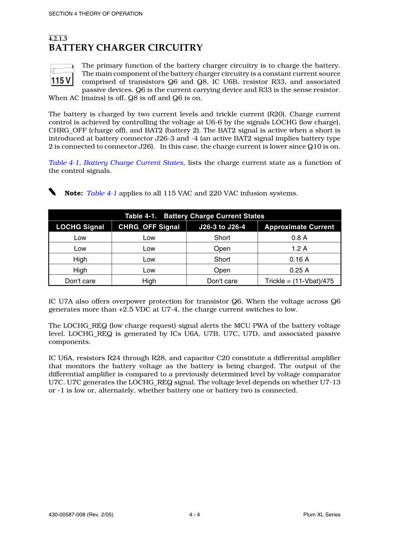
The battery is charged by two current levels and trickle current (R20). Charge currentcontrol is achieved by controlling the voltage at U6-6 by the signals LOCHG (low charge),CHRG_OFF (charge off), and BAT2 (battery 2). The BAT2 signal is active when a short isintroduced at battery connector J26-3 and -4 (an active BAT2 signal implies battery type2 is connected to connector J26). In this case, the charge current is lower since Q10 is on.
Table 4-1, Battery Charge Current States, lists the charge current state as a function ofthe control signals.
Note: Table 4-1 applies to all 115 VAC and 220 VAC infusion systems.
IC U7A also offers overpower protection for transistor Q6. When the voltage across Q6generates more than +2.5 VDC at U7-4, the charge current switches to low.
The LOCHG_REQ (low charge request) signal alerts the MCU PWA of the battery voltagelevel. LOCHG_REQ is generated by ICs U6A, U7B, U7C, U7D, and associated passivecomponents.
IC U6A, resistors R24 through R28, and capacitor C20 constitute a differential amplifierthat monitors the battery voltage as the battery is being charged. The output of thedifferential amplifier is compared to a previously determined level by voltage comparatorU7C. U7C generates the LOCHG_REQ signal. The voltage level depends on whether U7-13or -1 is low or, alternately, whether battery one or battery two is connected.
Table 4-1. Battery Charge Current States
LOCHG Signal CHRG_OFF Signal J26-3 to J26-4 Approximate Current
Low Low Short 0.8 A
Low Low Open 1.2 A
High Low Short 0.16 A
High Low Open 0.25 A
Don't care High Don't care Trickle = (11-Vbat)/475
115 V
4.2 ELECTRONICS OVERVIEW
Technical Service Manual 4 - 5 430-00587-008 (Rev. 2/05)
4.2.2POWER SUPPLY PWA
The power supply PWA consists of switcher circuitry, voltage regulator circuitry,and battery charger circuitry. Refer to Figure 9-24, Power Supply PWA Schematic(XL International), or Figure 9-26, Power Supply PWA Schematic (XLMInternational). The power supply PWA includes the following operational modes:
AC (mains) off. Infusion system is not connected to mains voltage and is not operating
AC (mains) off, infusion system on. Infusion system is not connected to mains voltageand is operating
AC (mains) on. Infusion system is connected to mains voltage and is not operating
AC (mains) on, infusion system on. Infusion system is connected to mains voltageand is operating
4.2.2.1SWITCHER CIRCUITRY
The switcher circuitry converts AC (mains) voltage to an isolated +11 VDC powerthrough flyback topology.
Fuses F1 and F2, and variable resistors VR1 and VR2 provide protection againsthigh-line voltage spikes and abnormally high input power demands. Capacitors C1, C2,C35, C36, C37, and C38, transformer T1, and inductor L1 are designed for attenuatingthe conducted emissions. IC U1, resistor R1, inductor L1, and capacitor C3 provide theDC voltage required for conversion by the switcher. Diodes CR1, CR2, CR4, and CR15;resistors R22, R68, R73, and R74; capacitors C4, C9, and C34; and transistors Q11 andQ12 provide the DC voltage for IC U2, the current mode switcher controller IC.
A UL-544 isolation barrier surrounds transistor Q1, transformer T2, IC U2, and associatedpassive components to minimize radiated EMI. Optocoupler U3 is part of the mainregulation loop that provides the UL-544 isolation barrier.
IC U2 oscillates at approximately 40 kHz, a frequency dictated by the values of resistorR4 and capacitor C5. U2 controls the duty cycle of transistor switch Q1 through resistorsR5 and R6, and diode CR16. Resistor R9 provides the current sense and resistor R8 andcapacitor C7 filter the ramp voltage across R9 and feed it back to IC U2.
U2 configuration allows DC voltage at pin 9 (ERR+) to equal the peak voltage across resistorR9. This DC voltage controls the delivered power through transformer T2 to regulate theoutput voltage. Voltage at U2 pin 9 is limited to +1.25 VDC so that peak current throughtransistor Q1 is limited to 1.25 VDC divided by the value of resistor R9.
Resistors R61 and R72, diode CR5, and capacitor C6 provide transformer T2 winding shortprotection by applying the higher voltage across resistor R9 to the U2 inhibit input. C6and the input impedance at U2-4 apply the low hiccup frequency to protect transistor Q1.
Diode CR3 and the clamp winding of transformer T2 provide intermediate energy transferto capacitor C3 and limit the peak voltage across transistor Q1.
220 V
220 V
SECTION 4 THEORY OF OPERATION
430-00587-008 (Rev. 2/05) 4 - 6 Plum XL Series
At AC (mains) power-up, capacitor C12 provides delayed timing to permit the voltagepotential at U2-14 (Vcc) to reach its minimum level. Diode CR11, and capacitors C18, C23,and C24 rectify the transformer T2 voltage to create the main DC voltage source for theinfusion system. Diode CR10, resistor R23, IC U4, and capacitor C19 constitute asecondary +12 VDC control loop for protection in case of primary loop failure. Diode CR12and capacitor C25 create a feed-forward converted negative voltage across capacitor C25to switch transistor Q9 on through resistor R57 and diode CR14. The Q9 output,housekeeping DC (HKDC), provides the necessary voltage to power both the mainregulation loop and the charger circuitry. HKDC is at ground level when AC (mains) is offand diode CR14 inhibits unnecessary battery power drain. Resistors R58 through R60,capacitors C30 through C32, and IC U9 filter HKDC and create a stable +2.5 VDC referencevoltage (F2.5V). Both HKDC and F2.5V are at ground level when AC (mains) is off.
IC U8B, with resistors R7, R21, R39, R43 through R45, capacitor C27, and IC U3 constitutethe main loop control. Transistor Q7, resistor R42, and diode CR9 eliminate latch-up atAC (mains) power-up by enabling voltage regulation only after +BUSS reaches +9 VDC.
4.2.2.2VOLTAGE REGULATOR CIRCUITRY
VMOT voltage regulator circuitry (U8A, Q5, and Q4 and associated passivecomponents) is at 9.35 VDC when AC (mains) is on.
Transistor Q2 remains forward-biased by HKDC through diode CR9 and resistors R11 andR12. While transistor Q2 remains on, transistor Q3 is disabled to inhibit POWERHOLDand SPSTIN from affecting the voltage regulator circuitry.
When AC (mains) is off, transistor Q2 is disabled. If battery operation is required, transistorQ4 is turned on momentarily by the SPSTIN signal and permanently by POWERHOLDthrough transistor Q3. Since Q2 is off, transistor Q4 switches the battery voltage throughthe VMOT circuitry to supply voltage to the necessary circuits, including the +5 VDCregulator U5. IC U5, the +5 VDC low-drop voltage regulator, powers most of the digitalcircuits in the infusion system.
4.2.2.3BATTERY CHARGER CIRCUITRY
The primary part of the battery charger is the constant current source,comprised of transistors Q6 and Q8, IC U6B, resistor R33, and associatedpassive devices. Transistor Q6 is the current-carrying device, and resistor R33is the sense resistor. When AC (mains) is off, transistor Q8 is off and transistor
Q6 is on.
The battery is charged by two current levels and trickle current (resistor R20). Currentlevel is achieved by controlling the voltage at U6-6. IC U7A, transistor Q10, and resistorsR31, R32, R34, R62, and R63 control the voltage at U6-6, and hence, the current level.The BAT2 signal is high (not logic level) when a short is introduced at the battery connectorJ26 pins 3 and 4, which implies that battery type 2 is connected to connector J26. In thiscase, the battery charge current is low since transistor Q10 is on.
IC U7A also serves as an overpower protection for transistor Q6. When the voltage acrossQ6 generates more than 2.5V at U7-4, the charge current switches to low.
220 V
220 V
4.2 ELECTRONICS OVERVIEW
Technical Service Manual 4 - 7 430-00587-008 (Rev. 2/05)
The LOCHG_REQ signal alerts the MCU PWA of the battery voltage level; it is generatedby U6A, U7B, U7C, U7D and associated passive components.
IC U6A, resistors R24 through R28, and capacitor C20 constitute a differential amplifierthat reads the battery voltage as it is being charged. The output of the differential amplifieris compared to a previously determined level by U7C. U7C generates the LOCHG_REQ.The voltage level depends on whether U7-13 or U7-1 is low or, alternatively, whetherbattery type 1 or battery type 2 is connected.
4.2.3MCU PWA
The MCU PWA contains micro controller U6 (see Figure 9-15, MCU PWA Schematic (XL),Figure 9-16, MCU PWA Schematic (XLM), or Figure 9-17, MCU PWA Schematic(XLM with DataPort)). The MCU PWA has five digital ports and one analog port. Each portis eight lines wide. The MCU PWA also includes the following circuitry:
Watchdog
Serial communication
Alarm
Alarm power backup
Motor drivers
Pin detector
Universal asynchronous receiver/transmitter (UART) (XLM with DataPort)
4.2.3.1WATCHDOG CIRCUITRY
The watchdog circuitry continuously monitors the MCU PWA and contains IC U14. U14is strobed by micro controller U16 at a predetermined minimum frequency; otherwise, the*RESET output becomes active. *RESET also becomes active if digital voltage (VDIG) isout of range. *RESET causes the MCU PWA to reset, blocks any signal to the motors, andturns the alarm on.
4.2.3.2SERIAL COMMUNICATION CIRCUITRY
The serial communication circuitry interchanges data between the MCU PWA and eitherthe liquid crystal display (LCD) screen or the electrically erasable programmable read-onlymemory (EEPROM).
Although data is transmitted to both the LCD screen and the EEPROM, the clock is divertedonly to the selected receiver. If EE_CS is active, then *SCK appears as EE_CLK at IC U9C.If EE_CS is inactive, then *SCK is inverted to appear as LCD_CLK at IC U8B.
Data is read from either the LCD screen or the EEPROM. If EE_CS is active, then EE_DOappears as RXD at IC U7C. If EE_CS is inactive, then LCD_DO is inverted to appear asRXD at IC U7C.
SECTION 4 THEORY OF OPERATION
430-00587-008 (Rev. 2/05) 4 - 8 Plum XL Series
4.2.3.3ALARM CIRCUITRY (XL)
The alarm circuitry includes an oscillator circuit consisting of inverters U10C, U10B, andU10E. The oscillator circuit generates acoustic power at a predetermined frequency basedon the BUZ1 self resonance. Normally, the BUZZER signal is low, U9-10 is high, andresistor network RN8-7 and RN8-8 disables the oscillator. The alarm can be activated bythe BUZZER or *RESET signals becoming active and pulling RN8-7 down. When SW1 isset to LO, resistor R13 is electronically connected to the BUZ1-3 (buzzer drive) and thesound level decreases. U10D and U10F constitute a memory unit that disables theoscillator circuit when the U10F output is high.
At AC (mains) power-up, POWERHOLD becomes active and changes the U10D/U10Fmemory unit to enable the oscillator circuit. At a voluntary power-off, DIST_AIR_EN andPROX_AIR_EN become momentarily active. This momentary activation of DIST_AIR_ENand PROX_AIR_EN allows the memory unit to change to an oscillator-disabling state andthe alarm does not sound. At a catastrophic failure, however, the memory unit remainsenabled and the alarm sounds.
During a catastrophic failure, the alarm can be disabled by positioning the infusion systemcontrol knob to OFF/CHARGE.
4.2.3.4ALARM CIRCUITRY (XLM)
The alarm circuitry includes an oscillator circuit consisting of inverters U10C, U10B, andU10E. The oscillator circuit generates acoustic power at a predetermined frequency basedon the BUZ1 self resonance. Normally, the BUZZER signal is low, U9-10 is high, andresistor network RN8-7 and RN8-8 disables the oscillator. The alarm can be activated bythe BUZZER or *RESET signals becoming active and pulling RN8-7 down. U10D and U10Fconstitute a memory unit that disables the oscillator circuit when the U10F output is high.
At AC (mains) power-up, POWERHOLD becomes active and changes the U10D/U10Fmemory unit to enable the oscillator circuit. At a voluntary power-off, DIST_AIR_EN andPROX_AIR_EN become momentarily active. This momentary activation of DIST_AIR_ENand PROX_AIR_EN allows the memory unit to change to an oscillator-disabling state andthe alarm does not sound. At a catastrophic failure, however, the memory unit remainsenabled and the alarm sounds.
During a catastrophic failure, the alarm can be disabled by positioning the infusion systemcontrol knob to OFF/CHARGE.
The alarm circuitry provides sound for low-level settings only. For high-level sound, seeSection 4.2.4, Buzzer PWA (XLM).
4.2.3.5ALARM POWER BACKUP CIRCUITRY
The alarm power backup circuitry is provided through super capacitor C34. C34 offerspower backup in the event of a catastrophic failure. Diodes CR15, CR19, and CR20 routethe power for alarm driver U10 from VDIG or C34.
4.2 ELECTRONICS OVERVIEW
Technical Service Manual 4 - 9 430-00587-008 (Rev. 2/05)
4.2.3.6MOTOR DRIVER CIRCUITRY
The motor driver circuitry energizes the three stepper motors: plunger, input/output, andprimary/secondary. The MCU PWA micro controller, U6, outputs MOTPHAS1 andMOTPHAS2 to inverters U9A and U9F which generate two additional signals: *MOTPHAS1and *MOTPHAS2. These four signals are required to step the motors. Three motor enablesignals manage the motor step width. The motor enable signals are: MOTPLN_EN (motorplunger enable), MOTIO_EN (motor input/output enable), and MOTPS_EN (motorprimary/secondary enable). The four motor stepping signals activate ICs U2A, U3A, U3D,and U2D; or U2B, U3B, U3C, and U2C; or U5D, U5A, U4A, and U4D to switch the powermetal-oxide semiconductor field-effect transistors (MOSFETs) Q1 through Q4, Q5 throughQ8, or Q9 through Q12. When active, *RESET disables motor activity.
4.2.3.7PIN DETECTOR CIRCUITRY
The pin detector circuitry detects the primary and secondary valve pin motion. WhenPSV_EN is active, *PSV_EN becomes active and a constant current flows throughlight-emitting diode (LED) CR1 and LED CR2. CR1 and CR2 are located in the pin detectorsensor assembly mounted on the bubble sensor PWA. If *P_S_EN is active, IC U11A isactivated and U11B is de-activated, and vice versa. U11 serves as two hysteresiscomparators and its output, PS_VALVE, is edge detected by the MCU PWA. The positiveedges are detected by the MCU PWA INT1 input. The negative edges are detected by theMCU PWA PC3 input.
4.2.3.8UART (XLM WITH DATAPORT)
The UART used in the Plum XLM with DataPort infusion system is TL16C450 made byTexas Instruments. It is a complementary metal-oxide semiconductor (CMOS) field-effecttransistor (FET) version of an asynchronous communication element (ACE) typicallyfunctioning in a microcomputer system as a serial input/output interface.
The UART performs serial-to-parallel conversion on data received from the host computerand performs parallel-to-serial conversion on data received from the MCU. The MCU canread the status of the UART at any point in its operation. The status information includesthe type of transfer operation in progress, the status of the operation, and any errorconditions encountered.
The UART includes a programmable, on-board baud rate generator which is capable ofdividing a reference clock input by divisors from 1 to (216 -1) and producing a 16 x clockto drive the internal transmitter logic. Provisions are also included to use this 16 x clockto drive the receiver logic. In the Plum XLM with DataPort infusion system, data istransmitted and received at 1,200 bits per second. The 16 x clock is running at 19,200Hz (16 x 1,200).
SECTION 4 THEORY OF OPERATION
430-00587-008 (Rev. 2/05) 4 - 10 Plum XL Series
The UART includes a complete modem control capacity and a processor interrupt systemthat is software adjustable to user requirements to minimize the computing required tohandle the communication link. The software of the Plum XLM with DataPort infusionsystem programs the UART not to use its modem control capacity, but to interrupt theMCU when a byte of data is received from or transmitted to the host computer.
Note: Do not connect DataPort when infusing.
4.2.3.9NURSE CALL ALARM (XLM WITH DATAPORT - NURSE CALL)
During an alarm, an isolated contact closure is made by U22, a solid-state FET relay. TheBUZZER signal from the microprocessor is filtered to maintain the contact closure betweenshort beeps by the diode and RC network at the input to the driver U5.
The connection to the nurse call feature is made by an adapter that mates to the 15-pinserial port. The nurse call adapter connects to existing signalling equipment with a 1/4inch phone plug.
Note: Nurse call alarm is not available in IEC compliant infuser.
Note: Do not connect DataPort when infusing.
4.2.4BUZZER PWA (XLM)
The buzzer PWA is installed on the Plum XLM and XLM with DataPort (see Figure 9-28,Buzzer PWA Schematic). The buzzer PWA includes the following circuitry:
High volume audible alarm
Lockout switch
4.2.4.1HIGH VOLUME AUDIBLE ALARM
In addition to the MCU PWA alarm circuitry, a loud piezo alarm buzzer is installed on thebuzzer PWA for high volume setting (see Section 4.2.3.4, Alarm Circuitry (XLM)). The highvolume setting is selected by lever switch SW1. Switch SW1 is located on the buzzer PWA,and during normal operation is accessible on the rear enclosure.
The BUZZER_HI signal connects to the central processing unit (CPU) port on the MCUPWA. The SPSTIN_BUZ signal connects to the SPSTIN (+BUSS) signal on the MCU PWA.SPSTIN_BUZ is the battery charging voltage. When an alarm occurs, the processoractivates BUZZER_HI. When the switch SW1 is closed (high setting), the high volume piezobuzzer and the alarm circuitry on the MCU PWA activate. When switch SW1 is open (lowsetting), only the MCU PWA alarm circuitry activates.
EN-2
4.2 ELECTRONICS OVERVIEW
Technical Service Manual 4 - 11 430-00587-008 (Rev. 2/05)
4.2.4.2LOCKOUT SWITCH
The lockout switch SW2 is located on the buzzer PWA and is accessible on the rearenclosure of the Plum XLM. The lockout switch is connected to the LOCKOUT1 signal onthe display PWA, and to the LOCKOUT2 signal on the MCU PWA. LOCKOUT1 connects tothe collector of Q7 on the display PWA. When lockout switch SW2 is closed, and Q7saturates, LOCKOUT2 goes low and the LOCKED icon on the LCD illuminates.
4.2.5DISPLAY PWA
The display PWA receives serial data from the MCU PWA and displays it at the LCD (seeFigure 9-18, Display PWA Schematic (XL), or Figure 9-19, Display PWA Schematic (XLM)).The display PWA also includes most of the control knob functions required to operate theinfusion system. The display PWA includes the following circuitry: display,electroluminescent (EL) panel driver (XL), LED backlight panel and driver (XLM), RUNindicator, line power indicator, and control knob.
4.2.5.1DISPLAY CIRCUITRY (XL)
ICs U2 and U3 are master- and slave-type serial input LCD drivers and are cascaded toform a 92-segment (4 back-plane by 23 fore-plane) driver. LCD panel U1 is designed tomatch the drivers and has 88 segments.
Display data is serially clocked into U2 at pin 21. The clocking signal, LCD CLK, is receivedat U2-23 and U3-22. The drive frequency is not synchronized to the data input and isdictated by resistor R7. To eliminate a false display during data updates, U2 and U3 aredisabled by CR3, C14, R9, R8, and Q3.
4.2.5.2DISPLAY CIRCUITRY (XLM DISPLAY PWA -003 AND LOWER)
IC U2 is the 128 segment LCD driver that can drive the four backplanes and 32 frontplanes.LCD panel U4 has 110 front panel segments multiplexed with the four backplanes.
Display data is clocked serially into U2 via DIN (pin 39) and DCLK (pin 38). The LCD drivefrequency (approximately 100 Hz) is set by R7 and is not synchronized to the data inputinto U2.
4.2.5.3DISPLAY CIRCUITRY (XLM DISPLAY PWA -004 AND HIGHER)
IC U13 is the 128 segment LCD driver that can drive the four backplanes and 32frontplanes. LCD panel U4 has 110 front panel segments multiplexed with the fourbackplanes.
Display data is clocked serially into U13 via DATA (pin 58) and SCL (pin 57). The LCDdrive frequency (approximately 100 Hz) is set by R31 and is not synchronized to the datainput into U13.
SECTION 4 THEORY OF OPERATION
430-00587-008 (Rev. 2/05) 4 - 12 Plum XL Series
4.2.5.4EL PANEL DRIVER CIRCUITRY (XL)
Transistor Q1 and transformer T1 windings 1-3 (primary) and 4-2 (feedback) constitutethe main oscillator positive feedback. The T1 output winding (5, 8) provides a large-turnratio (to T1 primary winding) to boost the output to 300 volts peak-to-peak (Vpp). Thecapacitance of EL panel EL1 and the inductance of the T1 output winding dictates theoscillation frequency of 300 Hz to 500 Hz. As the capacitance of EL1 decreases becauseof aging, the frequency increases to maintain a constant brightness.
A control loop consisting of diode CR1; capacitors C13 and C10; resistors R13, R4, R3,and R6; IC U10B; and transistor Q2 maintains a constant output amplitude by rectifyingthe output and comparing it to the ELON signal.
4.2.5.5LED BACKLIGHT PANEL AND DRIVER (XLM)
The display backlight panel is an array of 60 LEDs arranged as parallel elements of twoseries LEDs. The required drive voltage of the panel equals two LED voltage drops ofapproximately 4.2 VDC. The actual forward voltage changes with temperature and variesfrom panel to panel. Driving the panel with a constant current compensates for varyingvoltage requirements.
The XLM backlight panel requires approximately 200 mA for optimum brightness. Thecurrent is controlled utilizing a current mode switching technique enabling high efficiencyoperation with a wide power supply range of 7 to 11 volts. The signal VMOT is the supplyvoltage for the backlight constant current regulator.
Current through U5, LED panel, is regulated by Q3 operation until the voltage acrosscurrent sensing resistors R14, R23, and R24 exceeds a reference voltage of approximately96 mV. The voltage drop is filtered by R13 and C7 and then compared to the turn-offthreshold determined by the voltage divider R11 and R12. Comparator U3, pin 1 driveslow when the current through R14, R23, and R24 exceeds the turn-off threshold,discharging C4. U1 senses the quick discharge of C1 and then turns off Q1.
Q1 remains off while C4 charges via resistor R9. Q3 turns on when the the charge on C4exceeds the input voltage high threshold of U3, pin 2.
4.2.5.6RUN INDICATOR CIRCUITRY
LEDRUN, when active, turns LED1 on. IC U10A (Q8 XLM) functions as a constant currentsource to LED1 by maintaining constant voltage across resistor R20. The voltage isapproximately +3.33 VDC.
4.2.5.7LINE POWER INDICATOR CIRCUITRY
HKDC is active when the infusion system is operating on AC (mains), and turns on theline power indicator, LED2. HKDC brings transistor Q4 base voltage to VDIG + Vf throughR15 (Vf equals forward voltage of diode CR1). This base voltage change causes Q4 toconduct and the current through LED2 equals approximately VDIG divided by the valueof resistor R14.
4.2 ELECTRONICS OVERVIEW
Technical Service Manual 4 - 13 430-00587-008 (Rev. 2/05)
4.2.5.8CONTROL KNOB CIRCUITRY (XL)
The control knob circuitry consists of transistor Q5; rotary switch Hall-effect sensors U11through U15; reed switch S7; ICs U4, U5, and U7 through U9; and associated passivecomponents. The control knob circuitry senses the control knob position and sends theposition code to the MCU PWA. The HSENSEN signal, when active, switches transistor Q5on and allows the output of rotary switch Hall-effect sensors U11 through U15 to be gatedthrough ICs U4, U5, and U7 through U9. Resultant output conditions of rotary 0 (ROT0),ROT1, and ROT2 at ICs U9B, U7B, and U7A are sent to the MCU PWA as a three-bit coderepresenting the control knob position. The S7 reed switch output, SPSTIN is transferredto the power supply PWA. If more or less than one Hall-effect sensor position signal isactive, ROT0, ROT1, and ROT2 become active simultaneously to signify a failure. If thecontrol knob is set to the OFF/CHARGE position, *SESTIN is enabled.
4.2.5.9CONTROL KNOB CIRCUITRY (XLM)
The control knob circuitry consists of transistor Q5; rotary switch Hall-effect sensors U11through U15; reed switch S7; ICs U4, U5, U7, and U8; and associated passive components.The control knob circuitry senses the control knob position and sends the position codeto the MCU PWA. The HSENSEN signal, when active, switches transistor Q5 on and allowsthe output of rotary switch Hall-effect sensors U11 through U15 to be gated through ICsU4, U5, U7, and U8. Resultant output conditions of rotary 0 (ROT0), ROT1, and ROT2 atICs U7A, U7B, and U7D are sent to the MCU PWA as a three-bit code representing thecontrol knob position. The S7 reed switch output, SPSTIN is transferred to the powersupply PWA. If more or less than one Hall-effect sensor position signal is active, ROT0,ROT1, and ROT2 become active simultaneously to signify a failure. If the control knob isset to the OFF/CHARGE position, *SESTIN is enabled.
4.2.6SENSOR PWA
The sensor PWA consists of the following circuitry: pressure amplifier/filter, AC (mains)amplifier, voltage reference, opto interrupter, and EEPROM (see Figure 9-21, Sensor PWASchematic).
4.2.6.1PRESSURE AMPLIFIER/FILTER CIRCUITRY
The pressure amplifier circuitry (IC U7, resistors R6 and R11 through R16, and capacitorsC2 and C3) is a differential amplifier with an approximate gain of 600. Capacitors C2 andC3 are part of an automatic-zero system within U7. The combination of resistors R13 andR11 makes it possible for R12 (trimpot) to compensate for up to a 3 millivolt (mV) offsetinput from the strain gauge. In case of larger offsets, R13 must be removed from the sensorPWA. R12 is adjusted to approximately +0.7 VDC at distal pressure (DISTPRES) so thatnegative pressure spikes can be read by the MCU PWA.
The filter circuitry (resistors R1 and R3, capacitors C4 and C5, and IC U8A) constitutes atwo-pole, 30 Hz Bessel active filter. The filter alternates the 500 Hz automatic-zeroswitching frequency of U7 and other noise.
SECTION 4 THEORY OF OPERATION
430-00587-008 (Rev. 2/05) 4 - 14 Plum XL Series
4.2.6.2AC AMPLIFIER CIRCUITRY
The AC (mains) amplifier circuitry (IC U8A) processes negative spikes that may signify anocclusion on DISTPRES to a level manageable by the MCU PWA analog-to-digital (A/D)converter. The AC amplifier blocks slow pressure changes and amplifies the spikes to therequired level. The AC amplifier also divides into the logarithmic compression circuit(resistor R7 and diodes CR1 and CR3), the bias/high-pass circuit (capacitor C8 andresistor R10), and the amplifier circuit (IC U8B, resistors R4 and R9, and capacitor C7).The logarithmic compression circuit limits the amplitude of the negative spikes at highback-pressure. The bias/high pass circuit blocks the slow pressure changes and biasesthe AC (mains) amplifier to +2.5 VDC.
4.2.6.3VOLTAGE REFERENCE CIRCUITRY
The voltage reference circuitry consists of ICs U1 and U6; transistor Q1; diodes CR2 andCR5; resistors R17 through R20, R22, and R23; and capacitors C9, C11, and C12. R22,C11, and C12 filter VMOT. R18 biases the reference U1. U6B buffers the +2.5 VDC REF.The +2.5 VDC REF is boosted by Q1, U6A, and associated components to generate themain +3.75 VDC reference 3V75REF. CR2 limits 3V75REF to VDIG level to protect theMCU PWA micro controller, U6. CR5 protects the base-emitter junction of Q1.
4.2.6.4OPTO INTERRUPTER CIRCUITRY
When PSENSEN is active, transistors Q2 and Q3 drive all LEDs in ICs U2, U3, and U4with a constant current of approximately 22 milliamperes (mA). Resistor R24 limits thecurrent.
4.2.6.5EEPROM CIRCUITRY
The EEPROM circuitry (IC U5) communicates serially with the MCU PWA. U5 receivescommands and data through pin 3 as TXD. Stored data is transferred through pin 4 asEE_DO. When EE_CS is active at pin 1 and EE_CLK (pin 2) is in synchronization withTXD, U5 is enabled.
4.2.7BUBBLE SENSOR PWA
The bubble sensor PWA consists of the following circuitry: transmitter, receiver (whichincludes two channels, proximal and distal), and pin detector flex (see Figure 9-21, SensorPWA Schematic, and Figure 9-22, Pin Detector Flex Circuit Schematic).
Note: Both proximal and distal sensors can transmit or receive.
4.2 ELECTRONICS OVERVIEW
Technical Service Manual 4 - 15 430-00587-008 (Rev. 2/05)
4.2.7.1TRANSMITTER CIRCUITRY
The transmitter circuitry consists of a sweep oscillator, a voltage-controlled oscillator(VCO), and a driver.
The sweep oscillator (ICs U1A and portion of U2, capacitor C5, and resistor R15 throughR18) oscillates at approximately 12 kHz with a 50 percent duty cycle. A CMOS gate withinU2 is used for a quality rail-to-rail symmetrical signal for greater timing accuracy. Theoutput of the sweep oscillator (C2) is between +2 VDC and +3 VDC. The C2 output is usedto sweep the VCO at U2-9.
IC U2, capacitor C7, and resistor R21 constitute the VCO. U2 is originally a phase-lockloop (PLL) IC with the VCO portion sweeping output frequencies from 4 MHz to 6 MHz.The VCO center frequency is determined by R21 and C7. Activating either signal,PROX_AIR_EN or DIST_AIR_EN, enables the VCO.
The driver consists of a push-pull, emitter-follower complementary pair of transistors: Q4and Q5. The driver supplies input to proximal sensor X1 and distal sensor X2.
4.2.7.2RECEIVER CIRCUITRY
The receiver consists of an amplifier, detector, and buffer.
The amplifier consists of transistors Q3, Q6, Q2, and associated passive components. Theamplifier is biased by 2V5REF and is designed for wide power supply range. Q3 is biasedby PROX_AIR_EN in order to receive from proximal sensor X1. Q6 is biased byDIST_AIR_EN to receive from distal sensor X2.
The detector is an emitter-follower transistor Q1. Q1 allows maximum input impedance.Capacitor C1 and resistor R4 constitute a time constant of 200 microseconds (µS). Sincethe time between peaks is approximately 40 µS, the output (*AIR_OPT) remains high witha pronounced sawtooth ripple.
The buffer (IC U1A and resistors R7 and R2) also amplifies the detected signal.
4.2.7.3PIN DETECTOR FLEX CIRCUITRY
The pin detector flex circuitry detects movement of the primary and secondary valve pinsby optical transmitters CR1 and CR2, and optical receivers Q1 and Q2. Light interruptersare attached to the pins and as the pins move, the appropriate valve movement signalsare transferred to the MCU PWA through the bubble sensor PWA.
SECTION 4 THEORY OF OPERATION
430-00587-008 (Rev. 2/05) 4 - 16 Plum XL Series
4.3MECHANICAL OVERVIEWThe principal mechanical elements of the infusion system include the cassette and themechanism assembly. When a cassette is locked into the operating position and the controlknob is turned on, the infusion system performs a self test to verify the integrity of theinternal systems. The operation of the mechanism assembly moves a plunger, causing apumping action. A valve motor selects the primary or secondary valve, depending on thecommand. An additional valve motor alternately opens and closes an inlet valve and outletvalve to control fluid flow through the cassette pumping chamber.
The following sections detail the cassette and the mechanism assembly.
4.3.1CASSETTE
The cassette operates on a fluid displacement principle to volumetrically deliver fluid (see Figure 4-1, Major Elements of the Dual-Channel Cassette, and Figure 4-2, Fluid Pathin the Cassette). Refer to the system operating manual for a description of the majorcassette functions.
The pumping cycle begins when the outlet valve is opened and the inlet valve is closed.The plunger extends to deflect the cassette diaphragm and expel fluid. At the end of thepumping stroke, the outlet valve closes, the inlet opens, the appropriate primary orsecondary valve opens, and the plunger retracts to allow fluid to refill the pumpingchamber. After the pumping chamber is filled, the inlet and outlet valves are reversed, theprimary and secondary valves are closed, and the cycle is repeated.
The cassette contains two chambers: an upper air trap chamber and a pumping chamber.The two chambers are separated by an inlet valve (see Figure 4-1 and Figure 4-2) andoperate together to detect air. The upper air-trap chamber receives fluid from theintravenous (IV) container through either the primary or secondary valve. The upperair-trap chamber collects air bubbles from the IV line and container to prevent them fromentering the pumping chamber; the chamber can collect a substantial amount of air. Thecontroller tracks the amount of air collected in the upper air-trap chamber. If apredetermined air collection threshold is exceeded, the controller starts an infusion systembackprime and initiates a secondary display.
A proximal air-in-line sensor (bubble detector) is located between the primary/secondaryvalves and the upper air-trap chamber. The proximal air-in-line sensor detects air enteringthe upper air-trap chamber and initiates an audible alarm if the predetermined aircollection threshold is exceeded. Similarly, a second air-in-line sensor located distal to thepumping chamber initiates an audible alarm if a predetermined amount of air is detected.
The pumping chamber receives fluid from the upper air-trap chamber through an inletvalve. When the diaphragm covering the pumping chamber is deflected by the plunger,the pumping chamber expels fluid through an outlet valve. A pressure sensor located distalto the pumping chamber monitors pressure on the distal side of the cassette.
A flow regulator is incorporated into the cassette distal end. This flow regulator is used tomanually control flow when the cassette is not inserted in the pump. When the cassetteis properly inserted into the infusion system and the infusion system door is closed, amechanism opens the flow regulator to allow the infusion system to control fluid flow.When the infusion system door is opened, the same mechanism closes the flow regulatorto disable fluid flow.
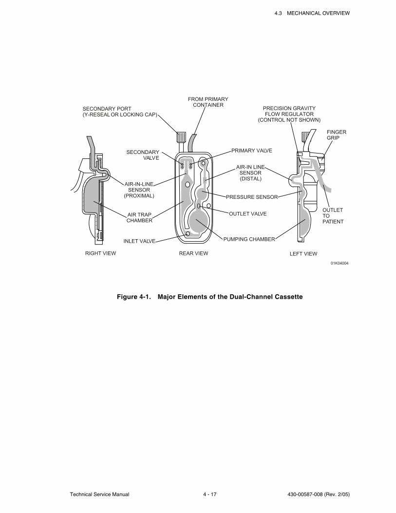
4.3 MECHANICAL OVERVIEW
Technical Service Manual 4 - 17 430-00587-008 (Rev. 2/05)
Figure 4-1. Major Elements of the Dual-Channel Cassette
01K04004
SECONDARY PORT
(Y-RESEAL OR LOCKING CAP)
FROM PRIMARY
CONTAINERPRECISION GRAVITY
FLOW REGULATOR
(CONTROL NOT SHOWN)
FINGER
GRIP
OUTLET
TO
PATIENT
LEFT VIEW
PRIMARY VALVE
AIR-IN LINE
SENSOR
(DISTAL)
PRESSURE SENSOR
OUTLET VALVE
REAR VIEW
PUMPING CHAMBER
RIGHT VIEW
INLET VALVE
AIR TRAP
CHAMBER
SECONDARY
VALVE
AIR-IN-LINE
SENSOR
(PROXIMAL)
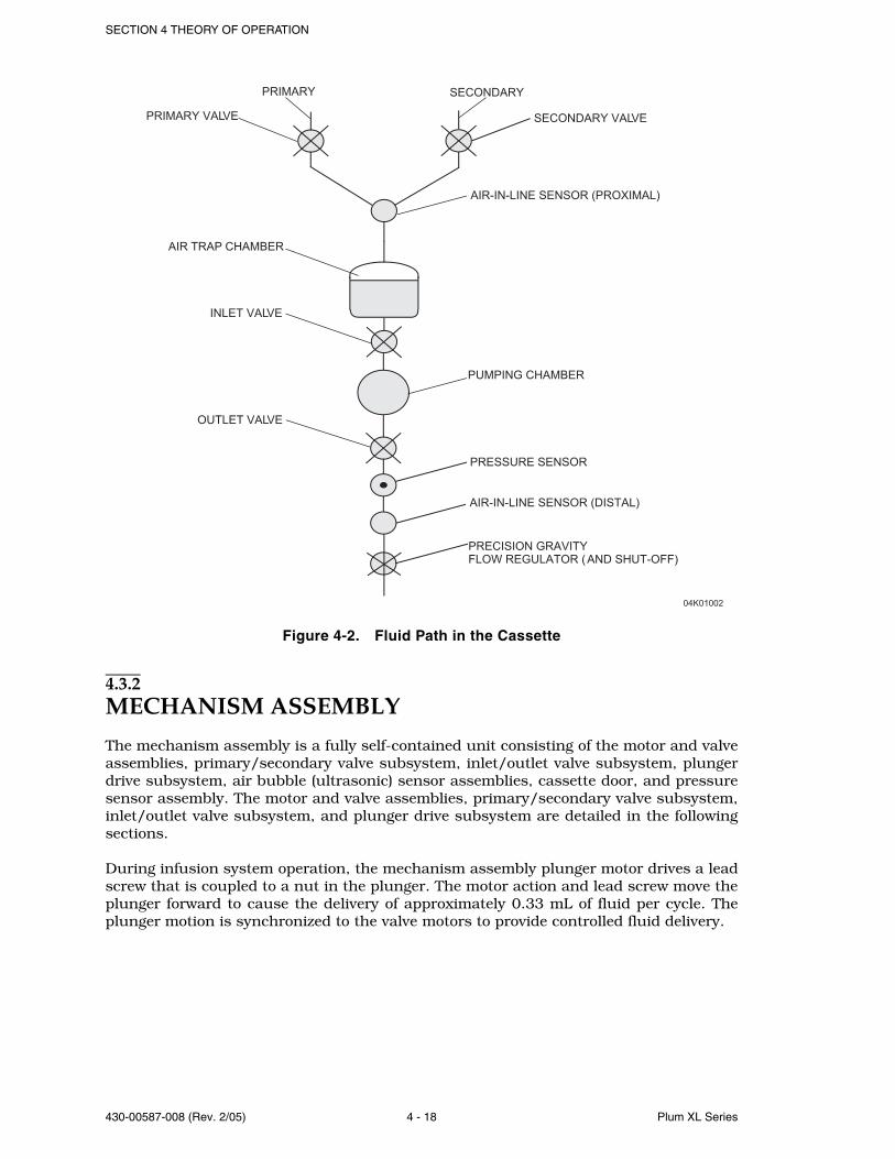
SECTION 4 THEORY OF OPERATION
430-00587-008 (Rev. 2/05) 4 - 18 Plum XL Series
Figure 4-2. Fluid Path in the Cassette
4.3.2MECHANISM ASSEMBLY
The mechanism assembly is a fully self-contained unit consisting of the motor and valveassemblies, primary/secondary valve subsystem, inlet/outlet valve subsystem, plungerdrive subsystem, air bubble (ultrasonic) sensor assemblies, cassette door, and pressuresensor assembly. The motor and valve assemblies, primary/secondary valve subsystem,inlet/outlet valve subsystem, and plunger drive subsystem are detailed in the followingsections.
During infusion system operation, the mechanism assembly plunger motor drives a leadscrew that is coupled to a nut in the plunger. The motor action and lead screw move theplunger forward to cause the delivery of approximately 0.33 mL of fluid per cycle. Theplunger motion is synchronized to the valve motors to provide controlled fluid delivery.
04K01002
PRIMARY
PRIMARY VALVE
AIR TRAP CHAMBER
INLET VALVE
OUTLET VALVE
PRESSURE SENSOR
SECONDARY VALVE
AIR-IN-LINE SENSOR (PROXIMAL)
SECONDARY
PUMPING CHAMBER
AIR-IN-LINE SENSOR (DISTAL)
PRECISION GRAVITY
FLOW REGULATOR ( AND SHUT-OFF)
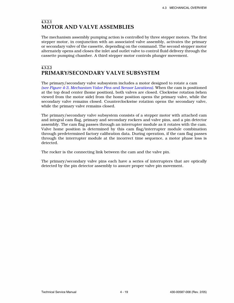
4.3 MECHANICAL OVERVIEW
Technical Service Manual 4 - 19 430-00587-008 (Rev. 2/05)
4.3.2.1MOTOR AND VALVE ASSEMBLIES
The mechanism assembly pumping action is controlled by three stepper motors. The firststepper motor, in conjunction with an associated valve assembly, activates the primaryor secondary valve of the cassette, depending on the command. The second stepper motoralternately opens and closes the inlet and outlet valve to control fluid delivery through thecassette pumping chamber. A third stepper motor controls plunger movement.
4.3.2.2PRIMARY/SECONDARY VALVE SUBSYSTEM
The primary/secondary valve subsystem includes a motor designed to rotate a cam (see Figure 4-3, Mechanism Valve Pins and Sensor Locations). When the cam is positionedat the top dead center (home position), both valves are closed. Clockwise rotation (whenviewed from the motor side) from the home position opens the primary valve, while thesecondary valve remains closed. Counterclockwise rotation opens the secondary valve,while the primary valve remains closed.
The primary/secondary valve subsystem consists of a stepper motor with attached camand integral cam flag, primary and secondary rockers and valve pins, and a pin detectorassembly. The cam flag passes through an interrupter module as it rotates with the cam.Valve home position is determined by this cam flag/interrupter module combinationthrough predetermined factory calibration data. During operation, if the cam flag passesthrough the interrupter module at the incorrect time sequence, a motor phase loss isdetected.
The rocker is the connecting link between the cam and the valve pin.
The primary/secondary valve pins each have a series of interrupters that are opticallydetected by the pin detector assembly to assure proper valve pin movement.
SECTION 4 THEORY OF OPERATION
430-00587-008 (Rev. 2/05) 4 - 20 Plum XL Series
Figure 4-3. Mechanism Valve Pins and Sensor Locations
4.3.2.3INLET/OUTLET VALVE SUBSYSTEM
The inlet/outlet valve subsystem is similar in function and build to the primary/secondaryvalve subsystem, but it does not contain a series of interrupters or a pin detectionassembly. Refer to Section 4.3.2.2, Primary/Secondary Valve Subsystem, for the inlet/outlet valve subsystem theory of operation.
4.3.2.4PLUNGER DRIVE SUBSYSTEM
The plunger drive subsystem includes a stepper motor. The stepper motor rotatesapproximately 1-2/3 revolutions per infusion system cycle to permit a 0.33 mL fluiddisplacement every infusion system cycle. The stepper motor then reverses and the plungerreturns to home position. This cycle repeats for the duration of fluid administration.Excluding the stepper motor, the plunger drive subsystem includes the followingcomponents: ball thrust bearing, screw/coupler assembly, and plunger/support system.
The ball thrust bearing is positioned against the mechanism assembly chassis. As theplunger extends into the cassette diaphragm to displace fluid, the resulting load (due topumping action and back pressure) is transferred axially through the ball thrust bearingto the mechanism assembly chassis.
The screw/coupler assembly links the motor and the plunger. This assembly includes aflag that passes through an interrupter module. This screw/coupler flag/interruptermodule combination is used in conjunction with predetermined factory calibration datato determine the plunger position.
During operation, if the screw/coupler flag passes through the interrupter module at theincorrect time sequence, a motor phase loss is detected.
PRIMARY VALVE
REGULATOR ACTUATOR
AIR-IN-LINE SENSOR
(DISTAL)
PRESSURE SENSOR
CASSETTE LOCATOR
OUTLET VALVE
PLUNGER
INLET VALVE
SECONDARY VALVE
(PIGGY BACK)
AIR-IN-LINE SENSOR
(PROXIMAL)
04K01003
Technical Service Manual 5 - 1 430-00587-008 (Rev. 2/05)
Section 5
MAINTENANCE AND SERVICE TESTS
A complete maintenance program promotes infusion longevity and trouble-free instrumentoperation. Such a program should include routine maintenance, periodic maintenanceinspection, and following any repair procedure, performance verification testing.
5.1ROUTINE MAINTENANCERoutine maintenance consists of basic inspection and cleaning procedures. As a minimumrequirement, inspect and clean the infusion pump after each use. In addition, establisha regular cleaning schedule for the infusion pump.
5.1.1INSPECTING THE INFUSION SYSTEM
Inspect the infusion system periodically for signs of defects such as worn accessories,broken instrument connections, or damaged cables. In addition, inspect the infusionsystem after repair or during cleaning. Replace any damaged or defective external parts.See Section 5.2.3, Inspection.
5.1.2CLEANING THE INFUSION SYSTEM
The following procedures are designed to maintain the infusion pump, sustain systemlongevity, and promote trouble-free instrument operation.
Follow hospital protocol for establishing the infusion pump cleaning schedule.
CAUTION: Do not immerse the infusion system in liquids. Immersion could damagethe instrument. Do not allow liquids to enter the infusion system electronicscompartment. Do not spray cleaning solutions toward any openings in the infusionsystem.
WARNING: DISCONNECT THE INFUSION SYSTEM FROM AC (MAINS)POWER PRIOR TO CLEANING THE INSTRUMENT. FAILURETO COMPLY WITH THIS WARNING COULD RESULT INELECTRICAL SHOCK.
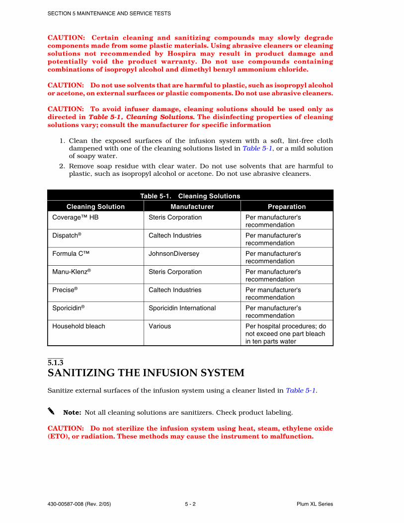
SECTION 5 MAINTENANCE AND SERVICE TESTS
430-00587-008 (Rev. 2/05) 5 - 2 Plum XL Series
CAUTION: Certain cleaning and sanitizing compounds may slowly degradecomponents made from some plastic materials. Using abrasive cleaners or cleaningsolutions not recommended by Hospira may result in product damage andpotentially void the product warranty. Do not use compounds containingcombinations of isopropyl alcohol and dimethyl benzyl ammonium chloride.
CAUTION: Do not use solvents that are harmful to plastic, such as isopropyl alcoholor acetone, on external surfaces or plastic components. Do not use abrasive cleaners.
CAUTION: To avoid infuser damage, cleaning solutions should be used only asdirected in Table 5-1, Cleaning Solutions. The disinfecting properties of cleaningsolutions vary; consult the manufacturer for specific information
1. Clean the exposed surfaces of the infusion system with a soft, lint-free clothdampened with one of the cleaning solutions listed in Table 5-1, or a mild solutionof soapy water.
2. Remove soap residue with clear water. Do not use solvents that are harmful toplastic, such as isopropyl alcohol or acetone. Do not use abrasive cleaners.
5.1.3SANITIZING THE INFUSION SYSTEM
Sanitize external surfaces of the infusion system using a cleaner listed in Table 5-1.
Note: Not all cleaning solutions are sanitizers. Check product labeling.
CAUTION: Do not sterilize the infusion system using heat, steam, ethylene oxide(ETO), or radiation. These methods may cause the instrument to malfunction.
Table 5-1. Cleaning Solutions
Cleaning Solution Manufacturer Preparation
Coverage™ HB Steris Corporation Per manufacturer's recommendation
Dispatch® Caltech Industries Per manufacturer's recommendation
Formula C™ JohnsonDiversey Per manufacturer's recommendation
Manu-Klenz® Steris Corporation Per manufacturer's recommendation
Precise® Caltech Industries Per manufacturer's recommendation
Sporicidin® Sporicidin International Per manufacturer’s recommendation
Household bleach Various Per hospital procedures; do not exceed one part bleach in ten parts water
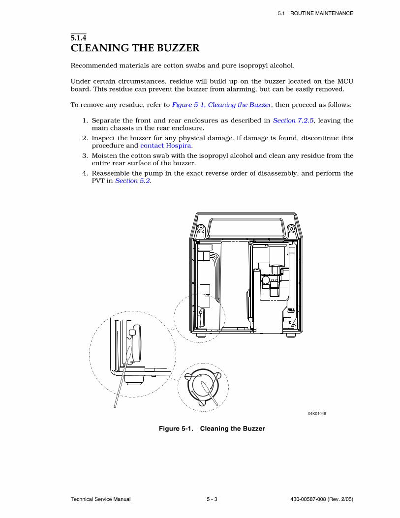
5.1 ROUTINE MAINTENANCE
Technical Service Manual 5 - 3 430-00587-008 (Rev. 2/05)
5.1.4CLEANING THE BUZZER
Recommended materials are cotton swabs and pure isopropyl alcohol.
Under certain circumstances, residue will build up on the buzzer located on the MCUboard. This residue can prevent the buzzer from alarming, but can be easily removed.
To remove any residue, refer to Figure 5-1, Cleaning the Buzzer, then proceed as follows:
1. Separate the front and rear enclosures as described in Section 7.2.5, leaving themain chassis in the rear enclosure.
2. Inspect the buzzer for any physical damage. If damage is found, discontinue thisprocedure and contact Hospira.
3. Moisten the cotton swab with the isopropyl alcohol and clean any residue from theentire rear surface of the buzzer.
4. Reassemble the pump in the exact reverse order of disassembly, and perform thePVT in Section 5.2.
Figure 5-1. Cleaning the Buzzer
04K01046
SECTION 5 MAINTENANCE AND SERVICE TESTS
430-00587-008 (Rev. 2/05) 5 - 4 Plum XL Series
5.2PERFORMANCE VERIFICATION TESTThe Perfomance Verification Test (PVT) consists of the tests described in the followingsections. The PVT can be used for diagnostic purposes during the troubleshooting of amalfunctioning infusion system. The PVT should be used for performance verificationbefore an infusion pump is placed back in service after repair. If any malfunction isdetected as a result of the PVT, refer to Table 6-6, PVT Troubleshooting.
Note: The PVT must be performed exactly as described in this manual to assureeffective and reliable product evaluation information.
5.2.1EQUIPMENT REQUIRED
The PVT requires the following equipment (or equivalents):
Graduated cylinder, 25 mL, with 0.2 mL graduations (Type A)
Sterile water or tap water in two IV bags/containers
Digital pressure meter, Fluke Biomedical DPM3
Safety analyzer, Fluke Biomedical 232D
Three-way stopcock, latex-free, List No. 03233-01 or 03232-01
Reflux valve (optional)
Six inch tubing extension, List No. 42362-01 (optional)
Special cassette with proximal bubble sensor tips removed
Special cassette with distal bubble sensor tips removed
LifeShield PlumSet, List No. 1642
LifeShield secondary set, List No. 11397
Digital multimeter (DMM), Fluke® 187
21-gauge needle, List No. 04492, or 18-gauge blunt cannula
Battery charger test box (optional)
Computer with a terminal emulator (optional)
RS-232 serial communication cable (optional)
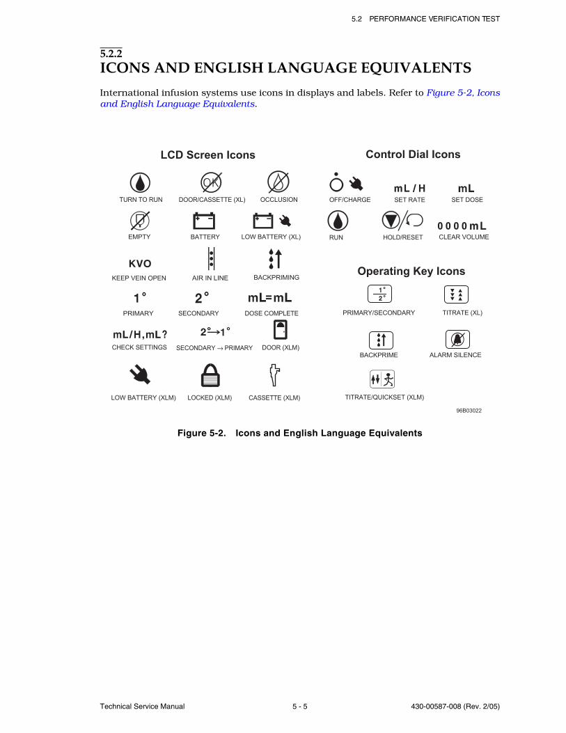
5.2 PERFORMANCE VERIFICATION TEST
Technical Service Manual 5 - 5 430-00587-008 (Rev. 2/05)
5.2.2ICONS AND ENGLISH LANGUAGE EQUIVALENTS
International infusion systems use icons in displays and labels. Refer to Figure 5-2, Iconsand English Language Equivalents.
Figure 5-2. Icons and English Language Equivalents
( )
SECONDARYPRIMARY DOSE COMPLETE
BACKPRIME ALARM SILENCE
PRIMARY/SECONDARY TITRATE (XL)
KEEP VEIN OPEN AIR IN LINE BACKPRIMING
RUN O / S
TURN TO RUN OCCLUSIONDOOR/CASSETTE (XL) SET RATE SET DOSEOFF/CHARGE
0 0 0 0BATTERY LOW BATTERY XL H LD RE ET CLEAR VOLUMEEMPTY
TITRATE/QUICKSET (XLM)
CHECK SETTINGS SECONDARY → PRIMARY DOOR (XLM)
CASSETTE (XLM)LOCKED (XLM)LOW BATTERY (XLM)
96B03022
LCD Screen Icons Control Dial Icons
Operating Key Icons
SECTION 5 MAINTENANCE AND SERVICE TESTS
430-00587-008 (Rev. 2/05) 5 - 6 Plum XL Series
5.2.3INSPECTION
Inspect the infusion system periodically for signs of defects such as worn accessories ordamaged cables. Also, inspect the infusion system after repair or during cleaning. Replaceany damaged or defective external parts.
Inspect the following areas for missing and damaged parts:
Note: Do not connect DataPort when infusing.
5.2.4TEST SETUP
To set up the infusion system for the PVT, proceed as follows:
1. Confirm the infusion system and appropriate accessories are fully assembled.
2. Hang two sterile water containers at a height of 18 to 24 inches (46 to 60 cm) abovethe pumping chamber of the infusion system.
3. Connect the infusion system to AC (mains) power. Conduct all tests with theinfusion system connected to AC (mains) power unless otherwise specified.
4. Verify the lockout switch is in the UNLOCKED (down) position (XLM only).
- Labels - Front panel label
- AC power cord - Control knob and all external screws
- Velcro® retainer strap - Pole clamp assembly
- Rubber foot pads - Front and rear enclosures
- Door assembly, shield, and handle - Battery access cover
- Cassette guide spring and roller - LCD screen
- Valve pins, plunger, bubble detectors, and locator pin
- DataPort connector (XLM with DataPort)
WARNING: A PATIENT SHOULD NEVER BE CONNECTED TO THEINFUSION SYSTEM DURING SYSTEM TESTING.
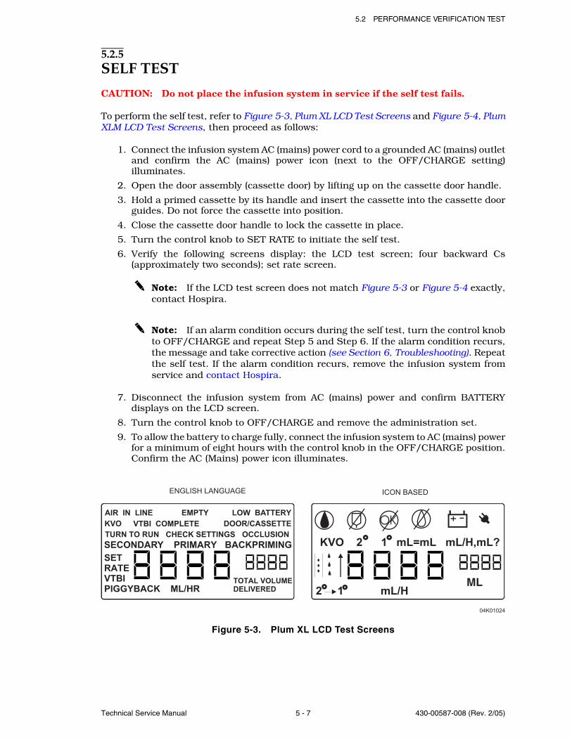
5.2 PERFORMANCE VERIFICATION TEST
Technical Service Manual 5 - 7 430-00587-008 (Rev. 2/05)
5.2.5SELF TEST
CAUTION: Do not place the infusion system in service if the self test fails.
To perform the self test, refer to Figure 5-3, Plum XL LCD Test Screens and Figure 5-4, PlumXLM LCD Test Screens, then proceed as follows:
1. Connect the infusion system AC (mains) power cord to a grounded AC (mains) outletand confirm the AC (mains) power icon (next to the OFF/CHARGE setting)illuminates.
2. Open the door assembly (cassette door) by lifting up on the cassette door handle.
3. Hold a primed cassette by its handle and insert the cassette into the cassette doorguides. Do not force the cassette into position.
4. Close the cassette door handle to lock the cassette in place.
5. Turn the control knob to SET RATE to initiate the self test.
6. Verify the following screens display: the LCD test screen; four backward Cs(approximately two seconds); set rate screen.
Note: If the LCD test screen does not match Figure 5-3 or Figure 5-4 exactly,contact Hospira.
Note: If an alarm condition occurs during the self test, turn the control knobto OFF/CHARGE and repeat Step 5 and Step 6. If the alarm condition recurs,the message and take corrective action (see Section 6, Troubleshooting). Repeatthe self test. If the alarm condition recurs, remove the infusion system fromservice and contact Hospira.
7. Disconnect the infusion system from AC (mains) power and confirm BATTERYdisplays on the LCD screen.
8. Turn the control knob to OFF/CHARGE and remove the administration set.
9. To allow the battery to charge fully, connect the infusion system to AC (mains) powerfor a minimum of eight hours with the control knob in the OFF/CHARGE position.Confirm the AC (Mains) power icon illuminates.
Figure 5-3. Plum XL LCD Test Screens
KVO 2 1 mL=mL mL/H,mL?
04K01024
ENGLISH LANGUAGE
2 1 mL/HML
AIR IN LINE EMPTY LOW BATTERY
KVO VTBI COMPLETE DOOR/CASSETTE
TURN TO RUN CHECK SETTINGS OCCLUSION
SECONDARY PRIMARY BACKPRIMING
SET
RATE
VTBI
PIGGYBACK ML/HR TOTAL VOLUME
DELIVERED
OK
ICON BASED
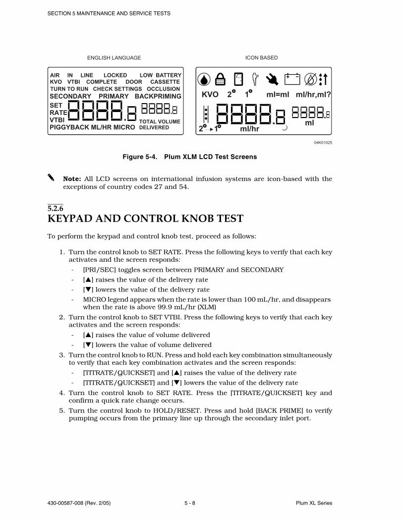
SECTION 5 MAINTENANCE AND SERVICE TESTS
430-00587-008 (Rev. 2/05) 5 - 8 Plum XL Series
Figure 5-4. Plum XLM LCD Test Screens
Note: All LCD screens on international infusion systems are icon-based with theexceptions of country codes 27 and 54.
5.2.6KEYPAD AND CONTROL KNOB TEST
To perform the keypad and control knob test, proceed as follows:
1. Turn the control knob to SET RATE. Press the following keys to verify that each keyactivates and the screen responds:
- [PRI/SEC] toggles screen between PRIMARY and SECONDARY
- [ ] raises the value of the delivery rate
- [ ] lowers the value of the delivery rate
- MICRO legend appears when the rate is lower than 100 mL/hr, and disappears when the rate is above 99.9 mL/hr (XLM)
2. Turn the control knob to SET VTBI. Press the following keys to verify that each keyactivates and the screen responds:
- [ ] raises the value of volume delivered
- [ ] lowers the value of volume delivered
3. Turn the control knob to RUN. Press and hold each key combination simultaneouslyto verify that each key combination activates and the screen responds:
- [TITRATE/QUICKSET] and [ ] raises the value of the delivery rate
- [TITRATE/QUICKSET] and [ ] lowers the value of the delivery rate
4. Turn the control knob to SET RATE. Press the [TITRATE/QUICKSET] key andconfirm a quick rate change occurs.
5. Turn the control knob to HOLD/RESET. Press and hold [BACK PRIME] to verifypumping occurs from the primary line up through the secondary inlet port.
KVO 2 1 ml=ml ml/hr,ml?
04K01025
ENGLISH LANGUAGE
2 1 ml/hr ml
AIR IN LINE LOCKED LOW BATTERY
KVO VTBI COMPLETE DOOR CASSETTE
TURN TO RUN CHECK SETTINGS OCCLUSION
SECONDARY PRIMARY BACKPRIMING
SET
RATE
VTBI
PIGGYBACK ML/HR MICROTOTAL VOLUME
DELIVERED
ICON BASED
5.2 PERFORMANCE VERIFICATION TEST
Technical Service Manual 5 - 9 430-00587-008 (Rev. 2/05)
5.2.7OPEN DOOR ALARM TEST
To perform the open door alarm test, proceed as follows:
1. Close the clamp on the secondary line (to prevent fluid in containers from mixing).
2. Open the cassette door. Verify the DOOR/CASSETTE (XL) or DOOR (XLM) legendappears and an alarm sounds.
3. Press [SILENCE]. Verify the alarm mutes.
4. Close the cassette door and unclamp the secondary line.
5.2.8ALARM LOUDNESS TEST (XL)
To perform the alarm loudness test, proceed as follows:
1. Turn the control knob to SET RATE and open the cassette door. Verify the DOOR/CASSETTE legend appears and an alarm sounds.
2. Toggle the audio switch (located on the infusion system bottom) between the highand low settings. Verify two alarm levels sound.
3. Press [SILENCE]. Verify the alarm mutes.
4. Close the cassette door.
5.2.9ALARM LOUDNESS AND LOCK FUNCTION TESTS (XLM)
To perform the alarm loudness and lock function tests, proceed as follows:
1. Turn the control knob to SET RATE and open the cassette door. Verify the DOORlegend appears and an alarm sounds.
2. Toggle the audio switch (located on the rear panel) between the high and lowsettings. Verify two alarm levels sound.
3. Press [SILENCE]. Verify the alarm mutes.
4. Close the cassette door.
5. Turn the control knob to HOLD/RESET, then back to RUN.
6. Press the LOCK button (located on the rear panel). Verify LOCKED appears on thedisplay.
7. Turn the control knob to any other position. Verify the infusion system stopspumping, an alarm sounds, and the display backlight and LOCKED flash.
8. Turn the control knob to RUN. Verify the infusion system starts to pump.
9. Press [SILENCE]. Verify that the alarm condition remains unchanged.
10. Press the LOCK button to clear the alarm condition.
SECTION 5 MAINTENANCE AND SERVICE TESTS
430-00587-008 (Rev. 2/05) 5 - 10 Plum XL Series
5.2.10BATTERY LEGEND TEST
To perform the battery legend test, proceed as follows:
1. Disconnect the infusion system from AC (mains) power.
2. Turn the control knob to SET RATE. Verify the line power indicator turns off andthe BATTERY legend turns on within five seconds.
3. Reconnect the infusion system to AC (mains) power after the battery legend check.
4. Turn the control knob to OFF/CHARGE.
5.2.11FREE FLOW TESTTo perform the free flow test, proceed as follows:
1. Insert a primed cassette into the infusion system.
2. Turn the control knob to SET RATE.
3. With the cassette door closed, check the distal end of tubing for fluid flow. Verify aminimal flow of fluid (a few drops maximum) occurs.
4. Open the cassette door and check the distal end of tubing for fluid flow. Verify aminimal flow of fluid (a few drops maximum) occurs.
Note: A small amount of fluid may be expelled from the cassette when openingor closing the door.
5. Close the cassette door and check the distal end of tubing for fluid flow. Verify aminimal flow of fluid (a few drops maximum) occurs.
6. Turn the control knob to OFF/CHARGE.
5.2.12PROXIMAL OCCLUSION TEST
To perform the proximal occlusion test, proceed as follows:
1. Turn the control knob to SET RATE. Set the rate to a value greater than 40 mL/hr.
2. Turn the control knob to RUN to start pumping fluid.
3. After several pumping cycles, clamp the tubing proximal to the cassette. After dropsstop falling through the sight chamber, verify that an occlusion alarm occurs withinthree pumping cycles.
4. Press [SILENCE] and unclamp the proximal tubing.
5. Turn the control knob to OFF/CHARGE.
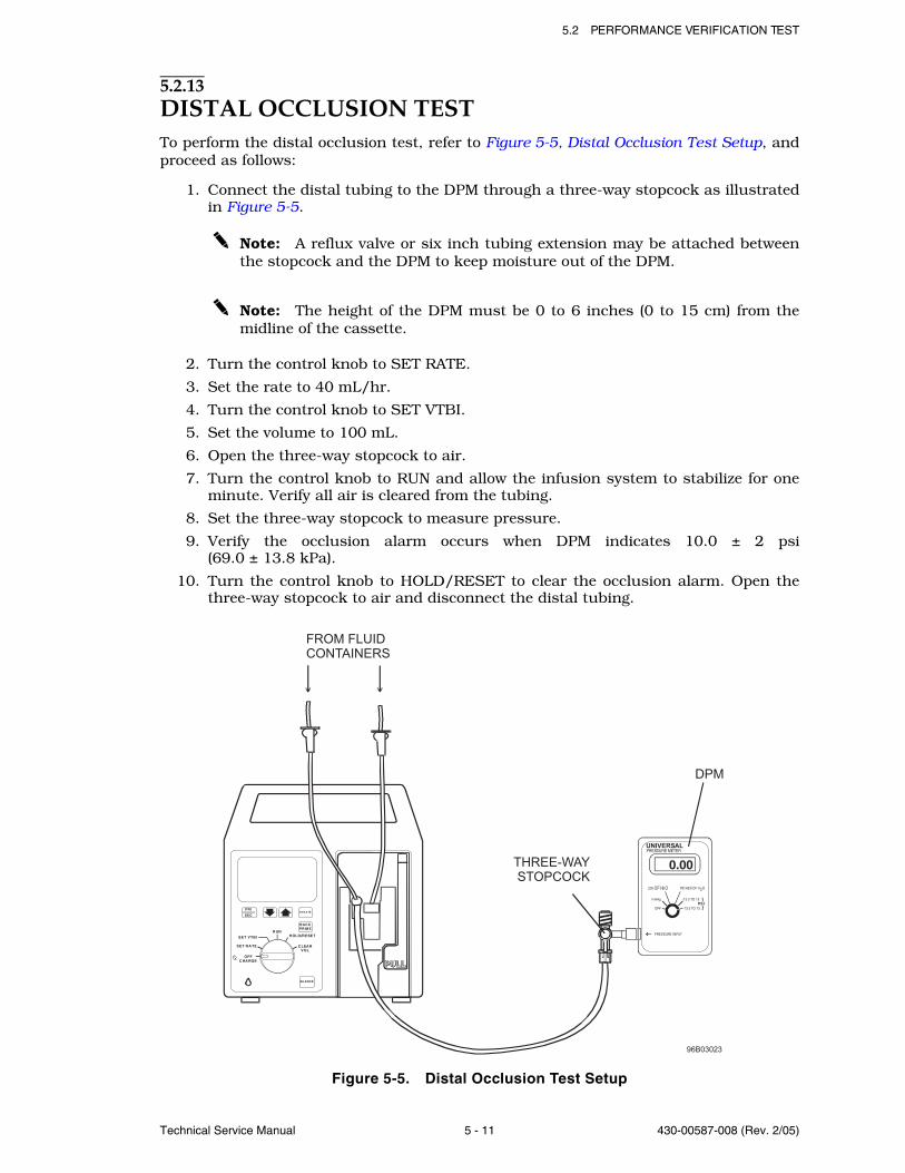
5.2 PERFORMANCE VERIFICATION TEST
Technical Service Manual 5 - 11 430-00587-008 (Rev. 2/05)
5.2.13DISTAL OCCLUSION TESTTo perform the distal occlusion test, refer to Figure 5-5, Distal Occlusion Test Setup, andproceed as follows:
1. Connect the distal tubing to the DPM through a three-way stopcock as illustratedin Figure 5-5.
Note: A reflux valve or six inch tubing extension may be attached betweenthe stopcock and the DPM to keep moisture out of the DPM.
Note: The height of the DPM must be 0 to 6 inches (0 to 15 cm) from themidline of the cassette.
2. Turn the control knob to SET RATE.
3. Set the rate to 40 mL/hr.
4. Turn the control knob to SET VTBI.
5. Set the volume to 100 mL.
6. Open the three-way stopcock to air.
7. Turn the control knob to RUN and allow the infusion system to stabilize for oneminute. Verify all air is cleared from the tubing.
8. Set the three-way stopcock to measure pressure.
9. Verify the occlusion alarm occurs when DPM indicates 10.0 ± 2 psi(69.0 ± 13.8 kPa).
10. Turn the control knob to HOLD/RESET to clear the occlusion alarm. Open thethree-way stopcock to air and disconnect the distal tubing.
Figure 5-5. Distal Occlusion Test Setup
PRI
SECT IT R A TE
SILENCE
SET RATE
SET VTBI
RUN
BACKPRIM E
HOLD/RESET
CLEARVOL
OFFCHARGE
OFF
mmHg
cm OF H O2
-13.5 TO 15
-13.5 TO 75PSI
INCHES OF H O2
UNIVERSALPRESSURE METER
PRESSURE INPUT
0.00
FROM FLUID
CONTAINERS
THREE-WAY
STOPCOCK
DPM
96B03023
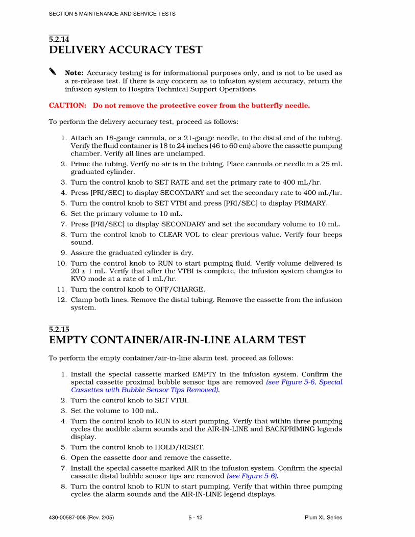
SECTION 5 MAINTENANCE AND SERVICE TESTS
430-00587-008 (Rev. 2/05) 5 - 12 Plum XL Series
5.2.14DELIVERY ACCURACY TEST
Note: Accuracy testing is for informational purposes only, and is not to be used asa re-release test. If there is any concern as to infusion system accuracy, return theinfusion system to Hospira Technical Support Operations.
CAUTION: Do not remove the protective cover from the butterfly needle.
To perform the delivery accuracy test, proceed as follows:
1. Attach an 18-gauge cannula, or a 21-gauge needle, to the distal end of the tubing.Verify the fluid container is 18 to 24 inches (46 to 60 cm) above the cassette pumpingchamber. Verify all lines are unclamped.
2. Prime the tubing. Verify no air is in the tubing. Place cannula or needle in a 25 mLgraduated cylinder.
3. Turn the control knob to SET RATE and set the primary rate to 400 mL/hr.
4. Press [PRI/SEC] to display SECONDARY and set the secondary rate to 400 mL/hr.
5. Turn the control knob to SET VTBI and press [PRI/SEC] to display PRIMARY.
6. Set the primary volume to 10 mL.
7. Press [PRI/SEC] to display SECONDARY and set the secondary volume to 10 mL.
8. Turn the control knob to CLEAR VOL to clear previous value. Verify four beepssound.
9. Assure the graduated cylinder is dry.
10. Turn the control knob to RUN to start pumping fluid. Verify volume delivered is20 ± 1 mL. Verify that after the VTBI is complete, the infusion system changes toKVO mode at a rate of 1 mL/hr.
11. Turn the control knob to OFF/CHARGE.
12. Clamp both lines. Remove the distal tubing. Remove the cassette from the infusionsystem.
5.2.15EMPTY CONTAINER/AIR-IN-LINE ALARM TEST
To perform the empty container/air-in-line alarm test, proceed as follows:
1. Install the special cassette marked EMPTY in the infusion system. Confirm thespecial cassette proximal bubble sensor tips are removed (see Figure 5-6, SpecialCassettes with Bubble Sensor Tips Removed).
2. Turn the control knob to SET VTBI.
3. Set the volume to 100 mL.
4. Turn the control knob to RUN to start pumping. Verify that within three pumpingcycles the audible alarm sounds and the AIR-IN-LINE and BACKPRIMING legendsdisplay.
5. Turn the control knob to HOLD/RESET.
6. Open the cassette door and remove the cassette.
7. Install the special cassette marked AIR in the infusion system. Confirm the specialcassette distal bubble sensor tips are removed (see Figure 5-6).
8. Turn the control knob to RUN to start pumping. Verify that within three pumpingcycles the alarm sounds and the AIR-IN-LINE legend displays.
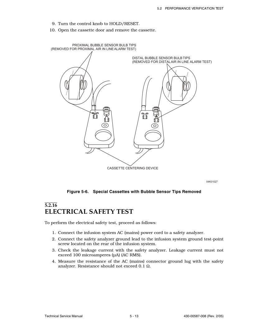
5.2 PERFORMANCE VERIFICATION TEST
Technical Service Manual 5 - 13 430-00587-008 (Rev. 2/05)
9. Turn the control knob to HOLD/RESET.
10. Open the cassette door and remove the cassette.
Figure 5-6. Special Cassettes with Bubble Sensor Tips Removed
5.2.16ELECTRICAL SAFETY TEST
To perform the electrical safety test, proceed as follows:
1. Connect the infusion system AC (mains) power cord to a safety analyzer.
2. Connect the safety analyzer ground lead to the infusion system ground test-pointscrew located on the rear of the infusion system.
3. Check the leakage current with the safety analyzer. Leakage current must notexceed 100 microamperes (µA) (AC RMS).
4. Measure the resistance of the AC (mains) connector ground lug with the safetyanalyzer. Resistance should not exceed 0.1 Ω.
PROXIMAL BUBBLE SENSOR BULB TIPS
(REMOVED FOR PROXIMAL AIR IN LINE ALARM TEST)
DISTAL BUBBLE SENSOR BULB TIPS
(REMOVED FOR DISTAL AIR IN LINE ALARM TEST)
CASSETTE CENTERING DEVICE
04K01027
SECTION 5 MAINTENANCE AND SERVICE TESTS
430-00587-008 (Rev. 2/05) 5 - 14 Plum XL Series
5.2.17END OF PERFORMANCE VERIFICATION TEST
If all tests have been successful, proceed as follows:
1. Clear the dose history.
2. Reset the infusion system to the original configuration.
3. Return the infusion system to service.
Note: If any tests fail, refer to Section 6, Troubleshooting, or contact HospiraTechnical Support Operations.
5.3PERIODIC MAINTENANCE INSPECTIONPeriodic maintenance inspections should be performed per hospital procedures forcompliance to accreditation requirements. It is recommended that JCAHO and/or hospitalprotocol be followed for establishing an infusion pump periodic maintenance inspectionschedule. Product specifications for this inspection are listed in Section 8, Specifications.To perform the periodic maintenance inspection, complete the performance verificationtest in Section 5.2.
5.4BATTERY OPERATION OVERVIEWThe infusion system is intended to operate on battery power on an exception basis only,such as emergency backup or temporary portable operation. Examples of emergencybackup include AC (mains) power failure or inadvertent disconnection of the AC (mains)power cord. An instance of temporary portable operation includes patient transfer fromone location to another.
The infusion system should be connected to AC (mains) power whenever possible to allowthe battery to remain fully charged. The infusion system line power indicator disappearsand the BATTERY legend appears when the infusion system is operating on battery power.
Factors that most commonly affect battery life are the depth and frequency of dischargeand the length of the recharge period. As a general rule, the more often the battery isdischarged and recharged the sooner it will need replacement. The primary cause ofdamage is leaving the battery in a less than fully charged state for any period of time.Battery damage can occur in a matter of hours and cause a permanent loss of batterycapacity. The amount of lost capacity depends on the degree of discharge, the storagetemperature, and the length of time the battery was stored in a discharged state.
Note: A permanently damaged battery cannot be recharged to full capacity.
When the battery discharges below the acceptable level while the infusion system isoperating, the alarm sounds and the LOW BATTERY message displays. Although it is notrecommended to continue operating the infusion system on battery power at this point,the battery will continue providing power until discharged. At this point, the infusionsystem enters the battery discharged mode and operation ceases.
5.4 BATTERY OPERATION OVERVIEW
Technical Service Manual 5 - 15 430-00587-008 (Rev. 2/05)
CAUTION: As soon as the LOW BATTERY alarm occurs, connect the infusion systemto AC (mains) power.
Recharging occurs any time the infusion system is connected to AC (mains) power. It isrecommended that the infusion system be connected to AC (mains) power wheneverpracticable to maximize available battery charge during transport or ambulation. Thepower switch does not have to be on for the battery to recharge. Recharging while theinfusion system is operating is rate dependent.
Note: The infusion system should be operated on battery power for six continuoushours at least once every six months for optimum battery performance and life.
5.4.1BATTERY CHARGER CURRENT TEST (OPTIONAL)
To perform the battery charger current test, refer to Figure 5-7, Battery Charger CurrentTest Configuration, then proceed as follows:
Note: Make certain the battery is in good condition and charged. If necessary, use asecond battery for this test.
1. Disconnect the infusion system from AC (mains) power. Remove the battery accesscover and disconnect the battery.
2. Connect the battery charger test circuit as illustrated in Figure 5-7. Make certainswitch S1 is in the off position.
3. Connect the infusion system to AC (mains) power and allow 20 seconds for thecurrent to stabilize. Read the current on the current meter.
4. Compare the measured current to the minimum and maximum values in Table 5-2,Battery Charger Current Test Parameters.
Note: If the reading is too low, the battery may be fully charged. Close switchS1; repeat Step 3 and verify per Table 5-2.
5. Disconnect the infusion system from AC (mains) power. Remove the battery chargertest circuit. Reconnect the battery to the infusion system. Replace the battery accesscover and secure.
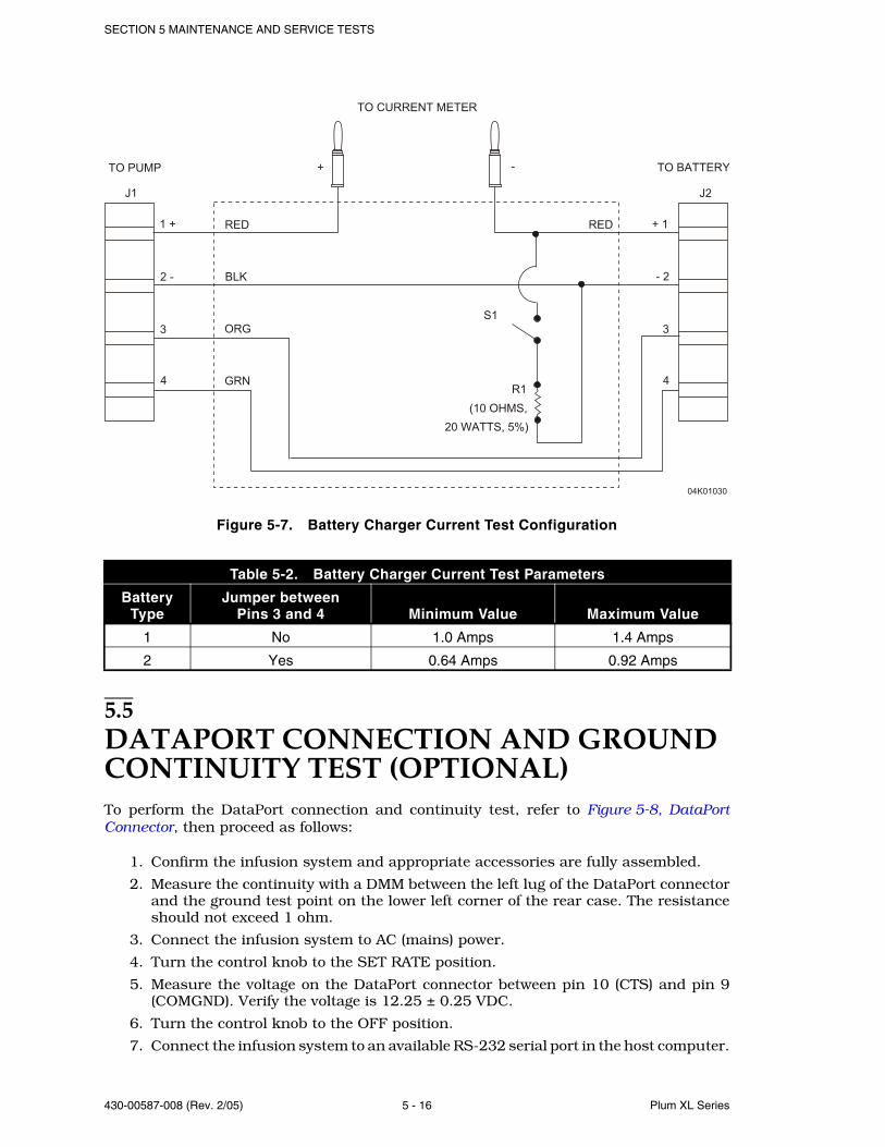
SECTION 5 MAINTENANCE AND SERVICE TESTS
430-00587-008 (Rev. 2/05) 5 - 16 Plum XL Series
Figure 5-7. Battery Charger Current Test Configuration
5.5DATAPORT CONNECTION AND GROUND CONTINUITY TEST (OPTIONAL)To perform the DataPort connection and continuity test, refer to Figure 5-8, DataPortConnector, then proceed as follows:
1. Confirm the infusion system and appropriate accessories are fully assembled.
2. Measure the continuity with a DMM between the left lug of the DataPort connectorand the ground test point on the lower left corner of the rear case. The resistanceshould not exceed 1 ohm.
3. Connect the infusion system to AC (mains) power.
4. Turn the control knob to the SET RATE position.
5. Measure the voltage on the DataPort connector between pin 10 (CTS) and pin 9(COMGND). Verify the voltage is 12.25 ± 0.25 VDC.
6. Turn the control knob to the OFF position.
7. Connect the infusion system to an available RS-232 serial port in the host computer.
Table 5-2. Battery Charger Current Test Parameters
Battery Type
Jumper betweenPins 3 and 4 Minimum Value Maximum Value
1 No 1.0 Amps 1.4 Amps
2 Yes 0.64 Amps 0.92 Amps
(10 OHMS,
20 WATTS, 5%)
R14
3
- 2
+ 1
TO BATTERY
J2
RED
-
TO CURRENT METER
+
S1
1 +
2 -
3
GRN
ORG
BLK
RED
4
TO PUMP
J1
04K01030
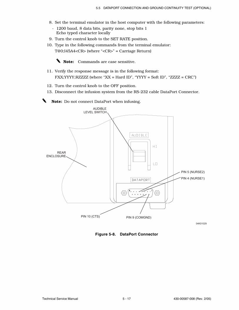
5.5 DATAPORT CONNECTION AND GROUND CONTINUITY TEST (OPTIONAL)
Technical Service Manual 5 - 17 430-00587-008 (Rev. 2/05)
8. Set the terminal emulator in the host computer with the following parameters:
- 1200 baud, 8 data bits, parity none, stop bits 1Echo typed character locally
9. Turn the control knob to the SET RATE position.
10. Type in the following commands from the terminal emulator:
T@0;I45A4<CR> (where “<CR>” = Carriage Return)
Note: Commands are case sensitive.
11. Verify the response message is in the following format:
FXX;YYYY;RZZZZ (where “XX = Hard ID”, “YYYY = Soft ID”, “ZZZZ = CRC”)
12. Turn the control knob to the OFF position.
13. Disconnect the infusion system from the RS-232 cable DataPort Connector.
Note: Do not connect DataPort when infusing.
Figure 5-8. DataPort Connector
PIN 10 (CTS) PIN 9 (COMGND)
1
AUDIBLE
LEVEL SWITCH
REAR
ENCLOSURE
8
04K01029
PIN 4 (NURSE1)
PIN 5 (NURSE2)

SECTION 5 MAINTENANCE AND SERVICE TESTS
430-00587-008 (Rev. 2/05) 5 - 18 Plum XL Series
5.6NURSE CALL FUNCTION TEST (OPTIONAL)To perform the nurse call function test, refer to Figure 5-8, then proceed as follows:
1. Confirm the infusion system and appropriate accessories are fully assembled.
2. Turn the control knob to the SET RATE position. Set the rate to a value greater than40 mL/hr.
3. Turn the control knob to SET VTBI position. Set volume to 100 mL.
4. Turn the control knob to RUN to start pumping fluid.
5. Measure the continuity between pin 4 and pin 5 with a DMM. Verify there is anopen circuit between the two pins.
6. After several pumping cycles, clamp the tubing proximal to the cassette. After dropsstop falling in the sight chamber, verify an occlusion alarms occurs within threepumping cycles.
7. Measure the continuity between pin 4 and pin 5 with the DMM. Verify there is aclosed circuit between the two pins.
8. Press [SILENCE] and unclamp the proximal tubing.
9. Verify the continuity between pin 4 and pin 5 changes back to an open circuit once[SILENCE] is pressed.
10. Turn the control knob to OFF/CHARGE.
Note: The nurse call alarm is not available in IEC compliant infusers. EN-2

Technical Service Manual 6 - 1 430-00587-008 (Rev. 2/05)
Section 6
TROUBLESHOOTING
This section contains information on obtaining technical assistance, and alarm messagesand error codes for the infusion system.
6.1TECHNICAL ASSISTANCE For technical assistance, product return authorization, and to order parts, accessories,or manuals within the United States, contact Hospira Technical Support Operations.
1-800-241-4002
For additional technical assistance, technical training, and product information, visit thewebsite at www.hospira.com.
Send all authorized, prepaid returns within the United States to the following address:
Hospira, Inc.Technical Support Operations
755 Jarvis DriveMorgan Hill, California 95037
For technical assistance, product return authorization, and to order parts, accessories,or manuals from outside the United States, contact the nearest Hospira sales office.
6.2ALARM MESSAGES AND ERROR CODESUnder most alarm conditions the infusion system ceases normal operation, generatesan audible alarm, and displays an alarm message or error code on the LCD screen.
There are two types of alarm conditions:
- alarm codes that can be cleared by the operator
- error codes that require qualified service personnel
See Table 6-1, Operational Alarm Messages and Corrective Actions, and Table 6-2, ErrorCodes Requiring Technical Service.
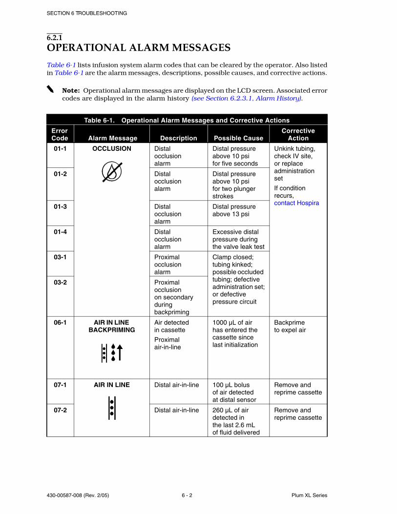
SECTION 6 TROUBLESHOOTING
430-00587-008 (Rev. 2/05) 6 - 2 Plum XL Series
6.2.1OPERATIONAL ALARM MESSAGES
Table 6-1 lists infusion system alarm codes that can be cleared by the operator. Also listedin Table 6-1 are the alarm messages, descriptions, possible causes, and corrective actions.
Note: Operational alarm messages are displayed on the LCD screen. Associated errorcodes are displayed in the alarm history (see Section 6.2.3.1, Alarm History).
Table 6-1. Operational Alarm Messages and Corrective Actions
Error Code Alarm Message Description Possible Cause
Corrective Action
01-1 OCCLUSION Distalocclusionalarm
Distal pressure above 10 psifor five seconds
Unkink tubing, check IV site,or replace administration set
If condition recurs,contact Hospira
01-2 Distalocclusionalarm
Distal pressure above 10 psifor two plunger strokes
01-3 Distalocclusionalarm
Distal pressure above 13 psi
01-4 Distalocclusionalarm
Excessive distal pressure during the valve leak test
03-1 Proximalocclusionalarm
Clamp closed; tubing kinked; possible occluded tubing; defective administration set;or defective pressure circuit
03-2 Proximal occlusionon secondary during backpriming
06-1 AIR IN LINE BACKPRIMING
Air detectedin cassette
Proximal air-in-line
1000 µL of airhas entered the cassette sincelast initialization
Backprimeto expel air
07-1 AIR IN LINE Distal air-in-line 100 µL bolusof air detectedat distal sensor
Remove and reprime cassette
07-2 Distal air-in-line 260 µL of air detected inthe last 2.6 mLof fluid delivered
Remove and reprime cassette

6.2 ALARM MESSAGES AND ERROR CODES
Technical Service Manual 6 - 3 430-00587-008 (Rev. 2/05)
08-1 AIR IN LINE BACKPRIMING
Emptycontaineralarm
500 µL of air detected entering the cassette inthe last two intake strokes
Change containerand backprimeto expel air
10-1 CHECK SETTINGS
mL/H=mL?
Checksettingsalarm
Rate and VTBI settings not correct
Turn control knob toSET RATEor SET VTBIto check settings or enter values
11-1 TURN TO RUN Turn to run alarm Rotary control knob not inOFF/CHARGEor RUN position, or no key is pressed forfive minutes
Turn control knob to RUN, OFF/CHARGE, or HOLD/RESET
12-1 VTBI COMPLETE
mL=mL
Primary VTBI complete alarm
The VTBI forthe primary channel hasbeen delivered
Discontinue infusion,or change container and program new VTBI setting
12-2 Secondary VTBI complete alarm
The VTBI forthe secondary channel hasbeen delivered
13-1 CASSETTE
DOOR/CASSETTE (XL only)
or
Input/output valve leaktest failure
Defective administration set
Cassette improperlyloaded or improperlyprimed
Turn control knob toOFF/CHARGE,open and close cassette door, then restart
If condition recurs, replace administration set
Turn control knob to OFF/CHARGE or HOLD/RESET, reprime cassette and restart
13-2 Primary/secondaryvalve leaktest failure
13-3 Valve leaktest failuredue to excessive signal noise
Fluid spillage around valve pins
Clean valve pins
Table 6-1. Operational Alarm Messages and Corrective Actions
Error Code Alarm Message Description Possible Cause
Corrective Action
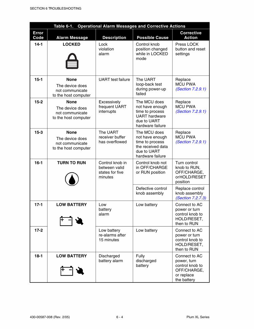
SECTION 6 TROUBLESHOOTING
430-00587-008 (Rev. 2/05) 6 - 4 Plum XL Series
14-1 LOCKED Lockviolationalarm
Control knob position changed while in LOCKED mode
Press LOCK button and reset settings
15-1 None
The device doesnot communicate
to the host computer
UART test failure The UART loop-back test during power-up failed
ReplaceMCU PWA(Section 7.2.9.1)
15-2 None
The device doesnot communicate
to the host computer
Excessively frequent UART interrupts
The MCU does not have enough time to process UART hardware due to UART hardware failure
ReplaceMCU PWA(Section 7.2.9.1)
15-3 None
The device doesnot communicate
to the host computer
The UART receiver buffer has overflowed
The MCU does not have enough time to process the received data due to UART hardware failure
ReplaceMCU PWA(Section 7.2.9.1)
16-1 TURN TO RUN Control knob in between valid states for five minutes
Control knob not in OFF/CHARGE or RUN position
Turn control knob to RUN, OFF/CHARGE,or HOLD/RESET position
Defective control knob assembly
Replace control knob assembly(Section 7.2.7.3)
17-1 LOW BATTERY Lowbatteryalarm
Low battery Connect to AC power or turn control knob to HOLD/RESET, then to RUN
17-2 Low battery re-alarms after 15 minutes
Low battery Connect to AC power or turn control knob to HOLD/RESET, then to RUN
18-1 LOW BATTERY Discharged battery alarm
Fullydischarged battery
Connect to AC power, turn control knob to OFF/CHARGE, or replacethe battery
Table 6-1. Operational Alarm Messages and Corrective Actions
Error Code Alarm Message Description Possible Cause
Corrective Action
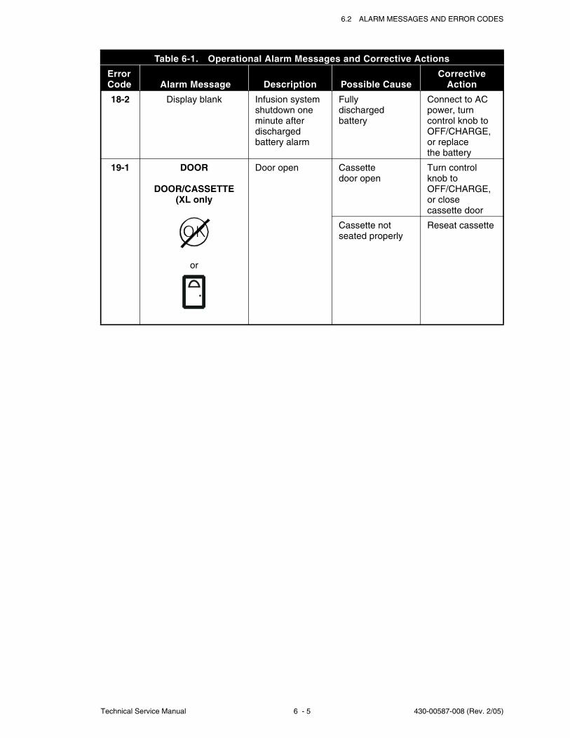
6.2 ALARM MESSAGES AND ERROR CODES
Technical Service Manual 6 - 5 430-00587-008 (Rev. 2/05)
18-2 Display blank Infusion system shutdown one minute after discharged battery alarm
Fullydischarged battery
Connect to AC power, turn control knob to OFF/CHARGE, or replacethe battery
19-1 DOOR
DOOR/CASSETTE (XL only
or
Door open Cassettedoor open
Turn control knob toOFF/CHARGE, or closecassette door
Cassette not seated properly
Reseat cassette
Table 6-1. Operational Alarm Messages and Corrective Actions
Error Code Alarm Message Description Possible Cause
Corrective Action
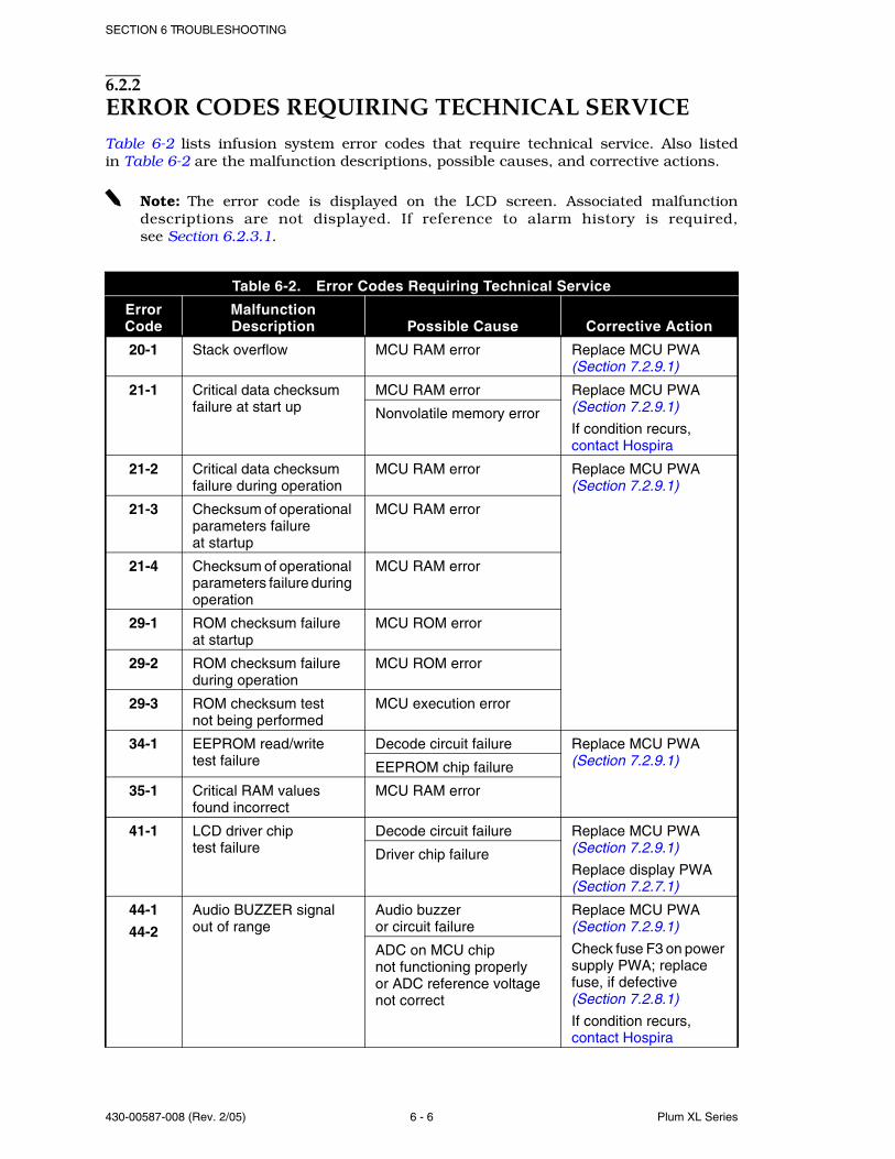
SECTION 6 TROUBLESHOOTING
430-00587-008 (Rev. 2/05) 6 - 6 Plum XL Series
6.2.2ERROR CODES REQUIRING TECHNICAL SERVICETable 6-2 lists infusion system error codes that require technical service. Also listedin Table 6-2 are the malfunction descriptions, possible causes, and corrective actions.
Note: The error code is displayed on the LCD screen. Associated malfunctiondescriptions are not displayed. If reference to alarm history is required,see Section 6.2.3.1.
Table 6-2. Error Codes Requiring Technical Service
Error Code
MalfunctionDescription Possible Cause Corrective Action
20-1 Stack overflow MCU RAM error Replace MCU PWA(Section 7.2.9.1)
21-1 Critical data checksum failure at start up
MCU RAM error Replace MCU PWA(Section 7.2.9.1)
If condition recurs,contact Hospira
Nonvolatile memory error
21-2 Critical data checksum failure during operation
MCU RAM error Replace MCU PWA(Section 7.2.9.1)
21-3 Checksum of operational parameters failureat startup
MCU RAM error
21-4 Checksum of operational parameters failure during operation
MCU RAM error
29-1 ROM checksum failureat startup
MCU ROM error
29-2 ROM checksum failure during operation
MCU ROM error
29-3 ROM checksum testnot being performed
MCU execution error
34-1 EEPROM read/writetest failure
Decode circuit failure Replace MCU PWA(Section 7.2.9.1)EEPROM chip failure
35-1 Critical RAM valuesfound incorrect
MCU RAM error
41-1 LCD driver chiptest failure
Decode circuit failure Replace MCU PWA(Section 7.2.9.1)
Replace display PWA(Section 7.2.7.1)
Driver chip failure
44-1
44-2
Audio BUZZER signalout of range
Audio buzzeror circuit failure
Replace MCU PWA(Section 7.2.9.1)
Check fuse F3 on power supply PWA; replace fuse, if defective(Section 7.2.8.1)
If condition recurs,contact Hospira
ADC on MCU chipnot functioning properlyor ADC reference voltagenot correct
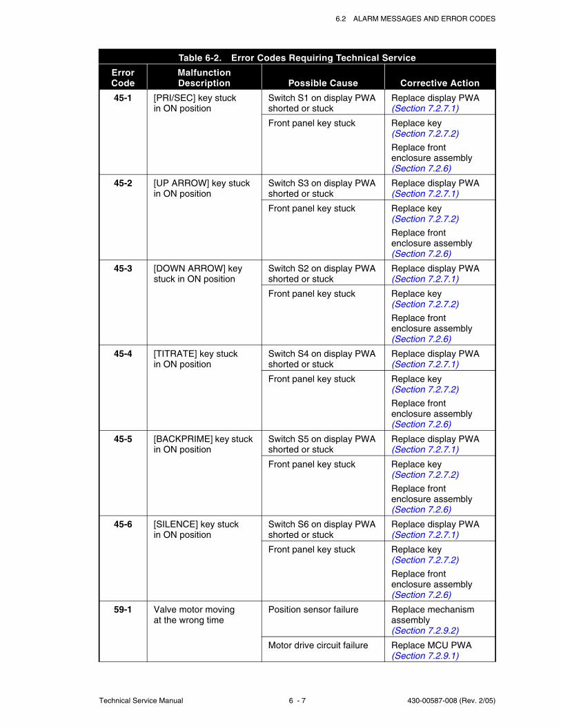
6.2 ALARM MESSAGES AND ERROR CODES
Technical Service Manual 6 - 7 430-00587-008 (Rev. 2/05)
45-1 [PRI/SEC] key stuckin ON position
Switch S1 on display PWA shorted or stuck
Replace display PWA(Section 7.2.7.1)
Front panel key stuck Replace key(Section 7.2.7.2)
Replace frontenclosure assembly(Section 7.2.6)
45-2 [UP ARROW] key stuckin ON position
Switch S3 on display PWA shorted or stuck
Replace display PWA(Section 7.2.7.1)
Front panel key stuck Replace key(Section 7.2.7.2)
Replace frontenclosure assembly(Section 7.2.6)
45-3 [DOWN ARROW] key stuck in ON position
Switch S2 on display PWA shorted or stuck
Replace display PWA(Section 7.2.7.1)
Front panel key stuck Replace key(Section 7.2.7.2)
Replace frontenclosure assembly(Section 7.2.6)
45-4 [TITRATE] key stuckin ON position
Switch S4 on display PWA shorted or stuck
Replace display PWA(Section 7.2.7.1)
Front panel key stuck Replace key(Section 7.2.7.2)
Replace frontenclosure assembly(Section 7.2.6)
45-5 [BACKPRIME] key stuck in ON position
Switch S5 on display PWA shorted or stuck
Replace display PWA(Section 7.2.7.1)
Front panel key stuck Replace key(Section 7.2.7.2)
Replace frontenclosure assembly(Section 7.2.6)
45-6 [SILENCE] key stuckin ON position
Switch S6 on display PWA shorted or stuck
Replace display PWA(Section 7.2.7.1)
Front panel key stuck Replace key(Section 7.2.7.2)
Replace frontenclosure assembly(Section 7.2.6)
59-1 Valve motor movingat the wrong time
Position sensor failure Replace mechanism assembly(Section 7.2.9.2)
Motor drive circuit failure Replace MCU PWA(Section 7.2.9.1)
Table 6-2. Error Codes Requiring Technical Service
Error Code
MalfunctionDescription Possible Cause Corrective Action
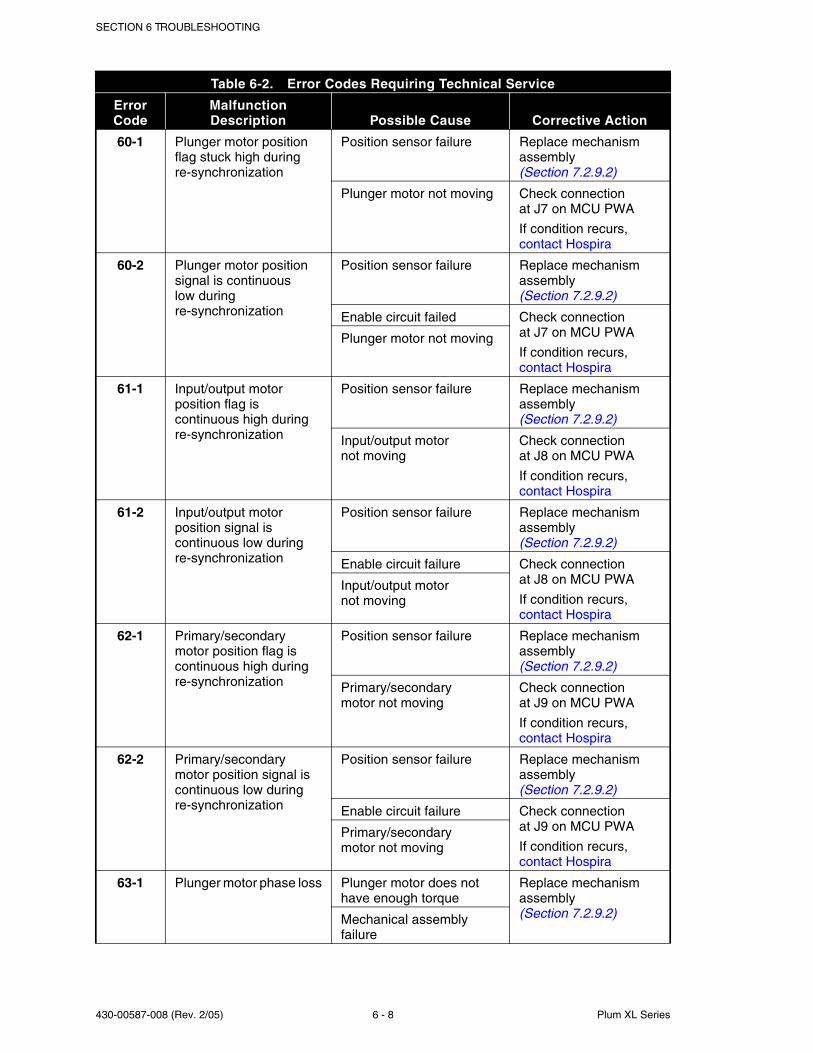
SECTION 6 TROUBLESHOOTING
430-00587-008 (Rev. 2/05) 6 - 8 Plum XL Series
60-1 Plunger motor position flag stuck high during re-synchronization
Position sensor failure Replace mechanism assembly(Section 7.2.9.2)
Plunger motor not moving Check connectionat J7 on MCU PWA
If condition recurs,contact Hospira
60-2 Plunger motor position signal is continuouslow during re-synchronization
Position sensor failure Replace mechanism assembly(Section 7.2.9.2)
Enable circuit failed Check connectionat J7 on MCU PWA
If condition recurs,contact Hospira
Plunger motor not moving
61-1 Input/output motor position flag iscontinuous high during re-synchronization
Position sensor failure Replace mechanism assembly(Section 7.2.9.2)
Input/output motornot moving
Check connectionat J8 on MCU PWA
If condition recurs,contact Hospira
61-2 Input/output motor position signal is continuous low during re-synchronization
Position sensor failure Replace mechanism assembly(Section 7.2.9.2)
Enable circuit failure Check connectionat J8 on MCU PWA
If condition recurs,contact Hospira
Input/output motornot moving
62-1 Primary/secondarymotor position flag iscontinuous high during re-synchronization
Position sensor failure Replace mechanism assembly(Section 7.2.9.2)
Primary/secondarymotor not moving
Check connectionat J9 on MCU PWA
If condition recurs,contact Hospira
62-2 Primary/secondarymotor position signal iscontinuous low during re-synchronization
Position sensor failure Replace mechanism assembly(Section 7.2.9.2)
Enable circuit failure Check connectionat J9 on MCU PWA
If condition recurs,contact Hospira
Primary/secondarymotor not moving
63-1 Plunger motor phase loss Plunger motor does not have enough torque
Replace mechanism assembly(Section 7.2.9.2)Mechanical assembly
failure
Table 6-2. Error Codes Requiring Technical Service
Error Code
MalfunctionDescription Possible Cause Corrective Action
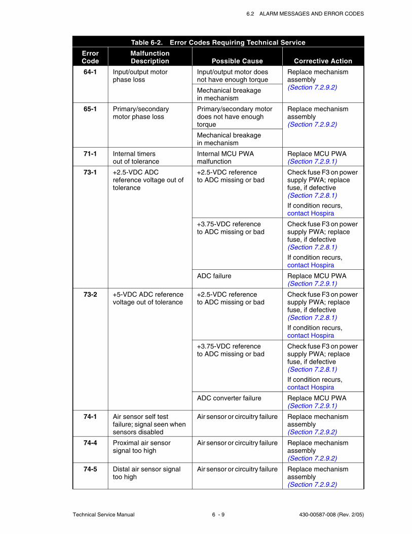
6.2 ALARM MESSAGES AND ERROR CODES
Technical Service Manual 6 - 9 430-00587-008 (Rev. 2/05)
64-1 Input/output motorphase loss
Input/output motor doesnot have enough torque
Replace mechanism assembly(Section 7.2.9.2)Mechanical breakage
in mechanism
65-1 Primary/secondarymotor phase loss
Primary/secondary motor does not have enough torque
Replace mechanism assembly(Section 7.2.9.2)
Mechanical breakagein mechanism
71-1 Internal timersout of tolerance
Internal MCU PWA malfunction
Replace MCU PWA(Section 7.2.9.1)
73-1 +2.5-VDC ADC reference voltage out of tolerance
+2.5-VDC referenceto ADC missing or bad
Check fuse F3 on power supply PWA; replace fuse, if defective(Section 7.2.8.1)
If condition recurs,contact Hospira
+3.75-VDC referenceto ADC missing or bad
Check fuse F3 on power supply PWA; replace fuse, if defective(Section 7.2.8.1)
If condition recurs,contact Hospira
ADC failure Replace MCU PWA(Section 7.2.9.1)
73-2 +5-VDC ADC reference voltage out of tolerance
+2.5-VDC referenceto ADC missing or bad
Check fuse F3 on power supply PWA; replace fuse, if defective(Section 7.2.8.1)
If condition recurs,contact Hospira
+3.75-VDC referenceto ADC missing or bad
Check fuse F3 on power supply PWA; replace fuse, if defective(Section 7.2.8.1)
If condition recurs,contact Hospira
ADC converter failure Replace MCU PWA(Section 7.2.9.1)
74-1 Air sensor self test failure; signal seen when sensors disabled
Air sensor or circuitry failure Replace mechanism assembly(Section 7.2.9.2)
74-4 Proximal air sensorsignal too high
Air sensor or circuitry failure Replace mechanism assembly(Section 7.2.9.2)
74-5 Distal air sensor signal too high
Air sensor or circuitry failure Replace mechanism assembly(Section 7.2.9.2)
Table 6-2. Error Codes Requiring Technical Service
Error Code
MalfunctionDescription Possible Cause Corrective Action
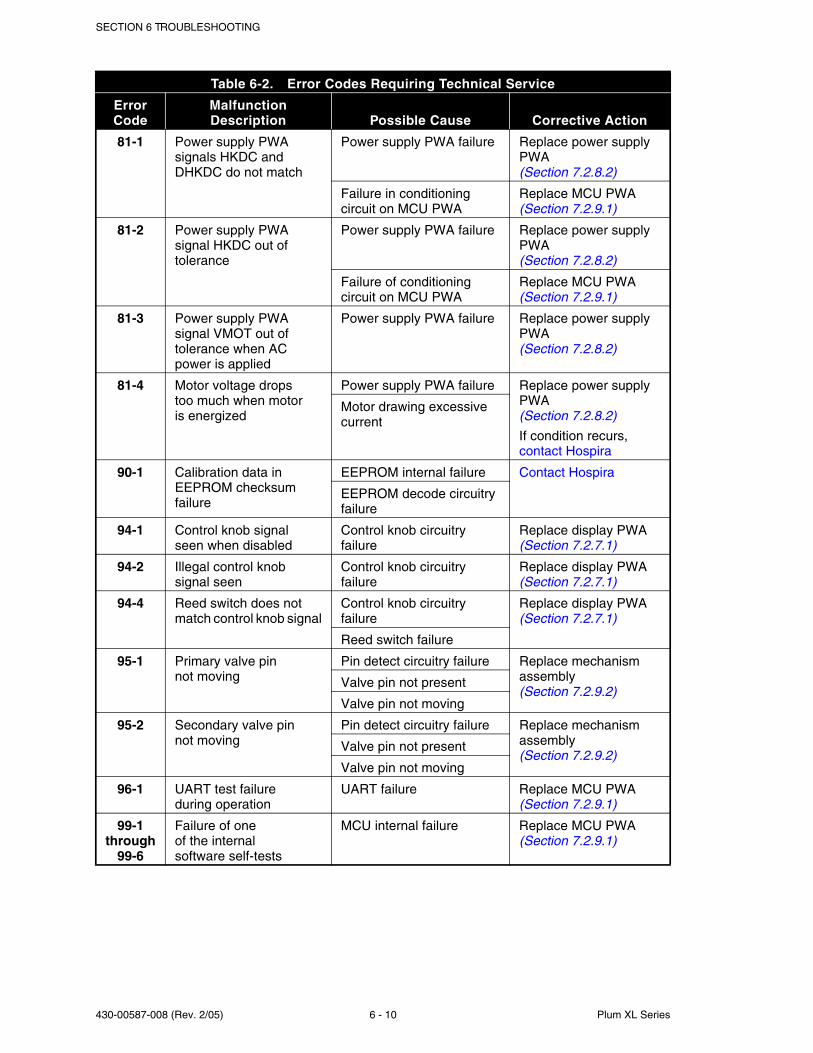
SECTION 6 TROUBLESHOOTING
430-00587-008 (Rev. 2/05) 6 - 10 Plum XL Series
81-1 Power supply PWA signals HKDC and DHKDC do not match
Power supply PWA failure Replace power supply PWA(Section 7.2.8.2)
Failure in conditioning circuit on MCU PWA
Replace MCU PWA(Section 7.2.9.1)
81-2 Power supply PWA signal HKDC out of tolerance
Power supply PWA failure Replace power supply PWA(Section 7.2.8.2)
Failure of conditioning circuit on MCU PWA
Replace MCU PWA(Section 7.2.9.1)
81-3 Power supply PWA signal VMOT out of tolerance when AC power is applied
Power supply PWA failure Replace power supply PWA(Section 7.2.8.2)
81-4 Motor voltage dropstoo much when motoris energized
Power supply PWA failure Replace power supply PWA(Section 7.2.8.2)
If condition recurs,contact Hospira
Motor drawing excessive current
90-1 Calibration data in EEPROM checksum failure
EEPROM internal failure Contact Hospira
EEPROM decode circuitry failure
94-1 Control knob signalseen when disabled
Control knob circuitry failure
Replace display PWA(Section 7.2.7.1)
94-2 Illegal control knobsignal seen
Control knob circuitry failure
Replace display PWA(Section 7.2.7.1)
94-4 Reed switch does not match control knob signal
Control knob circuitry failure
Replace display PWA(Section 7.2.7.1)
Reed switch failure
95-1 Primary valve pinnot moving
Pin detect circuitry failure Replace mechanism assembly(Section 7.2.9.2)
Valve pin not present
Valve pin not moving
95-2 Secondary valve pinnot moving
Pin detect circuitry failure Replace mechanism assembly(Section 7.2.9.2)
Valve pin not present
Valve pin not moving
96-1 UART test failureduring operation
UART failure Replace MCU PWA(Section 7.2.9.1)
99-1 through
99-6
Failure of oneof the internalsoftware self-tests
MCU internal failure Replace MCU PWA(Section 7.2.9.1)
Table 6-2. Error Codes Requiring Technical Service
Error Code
MalfunctionDescription Possible Cause Corrective Action
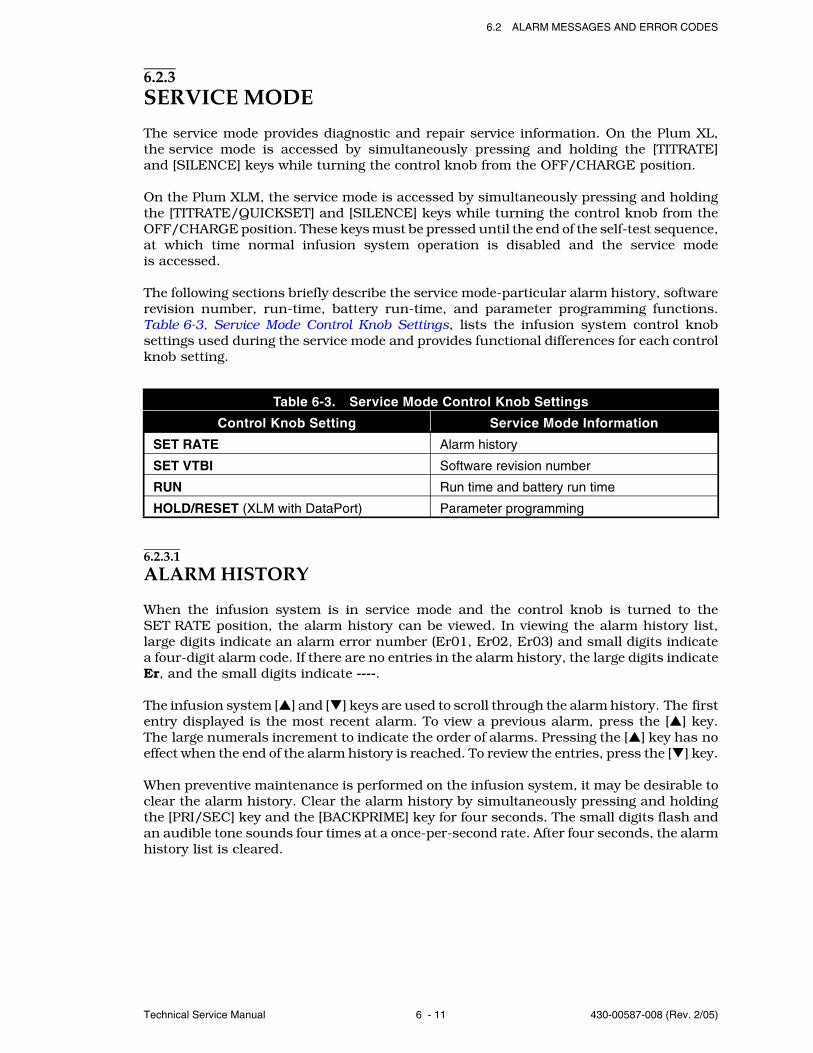
6.2 ALARM MESSAGES AND ERROR CODES
Technical Service Manual 6 - 11 430-00587-008 (Rev. 2/05)
6.2.3SERVICE MODE
The service mode provides diagnostic and repair service information. On the Plum XL,the service mode is accessed by simultaneously pressing and holding the [TITRATE]and [SILENCE] keys while turning the control knob from the OFF/CHARGE position.
On the Plum XLM, the service mode is accessed by simultaneously pressing and holdingthe [TITRATE/QUICKSET] and [SILENCE] keys while turning the control knob from theOFF/CHARGE position. These keys must be pressed until the end of the self-test sequence,at which time normal infusion system operation is disabled and the service modeis accessed.
The following sections briefly describe the service mode-particular alarm history, softwarerevision number, run-time, battery run-time, and parameter programming functions.Table 6-3, Service Mode Control Knob Settings, lists the infusion system control knobsettings used during the service mode and provides functional differences for each controlknob setting.
6.2.3.1ALARM HISTORY
When the infusion system is in service mode and the control knob is turned to theSET RATE position, the alarm history can be viewed. In viewing the alarm history list,large digits indicate an alarm error number (Er01, Er02, Er03) and small digits indicatea four-digit alarm code. If there are no entries in the alarm history, the large digits indicateEr, and the small digits indicate ----.
The infusion system [ ] and [ ] keys are used to scroll through the alarm history. The firstentry displayed is the most recent alarm. To view a previous alarm, press the [ ] key.The large numerals increment to indicate the order of alarms. Pressing the [ ] key has noeffect when the end of the alarm history is reached. To review the entries, press the [ ] key.
When preventive maintenance is performed on the infusion system, it may be desirable toclear the alarm history. Clear the alarm history by simultaneously pressing and holdingthe [PRI/SEC] key and the [BACKPRIME] key for four seconds. The small digits flash andan audible tone sounds four times at a once-per-second rate. After four seconds, the alarmhistory list is cleared.
Table 6-3. Service Mode Control Knob Settings
Control Knob Setting Service Mode Information
SET RATE Alarm history
SET VTBI Software revision number
RUN Run time and battery run time
HOLD/RESET (XLM with DataPort) Parameter programming

SECTION 6 TROUBLESHOOTING
430-00587-008 (Rev. 2/05) 6 - 12 Plum XL Series
6.2.3.2SOFTWARE REVISION NUMBER
When the infusion system is in service mode and the control knob is set to the SET VTBIposition, the software revision number can be viewed. The decimal point does not appearin the software revision number display, but is implied after the first digit. For example,if the display shows 105, the software revision number is 1.05. The software revisionnumber may be necessary when contacting Hospira.
6.2.3.3RUN TIME AND BATTERY RUN TIME
When the infusion system is in service mode and the control knob is set to the RUNposition, the run time and battery run time can be viewed. In the run time and batteryrun time display, large digits indicate the total infusion system run time in tens of hoursand the small digits indicate the battery run time in tens of hours. For example: if thelarge digits indicate 245 and the small digits indicate 79, the infusion system has beenoperated for a total of 2,450 hours and has also been operated on battery for 790 of those2,450 hours.
When replacing the battery, it may be desirable to clear the battery run time. To clear thebattery run time, simultaneously press and hold the [PRI/SEC] key and the [BACKPRIME]key for four seconds. The small digits flash and an audible tone sounds four times ata once-per-second rate. After four seconds, the battery run time is cleared. The totalinfusion system time cannot be cleared.
6.2.3.4PARAMETER PROGRAMMING (XLM WITH DATAPORT)
When the infusion system is in service mode and the control knob is set to HOLD/RESET,three sub-modes can be viewed and changed. Each of these three sub-modes are usedto change the value of an operational parameter of the infusion system as shown inTable 6-4, Sub-Modes of Parameter Programming.
The first sub-mode (communication selection) is the default sub-mode of parameterprogramming. Subsequently pressing the [BACKPRIME] key will change it to the secondsub-mode (soft ID), the third sub-mode (channel label), then to the first sub-mode. Withina sub-mode, the small digits indicate its index while the large digits indicate the currentvalue of the parameter to be viewed and programmed.
Table 6-4. Sub-Modes of Parameter Programming
Sub-Mode Name PurposeSub-Mode
Index
Communication SelectionTo select the communication withthe host computer
1
Soft ID To enter the soft ID of the infusion system 2
Channel Label To enter the channel label of the infusion system 3
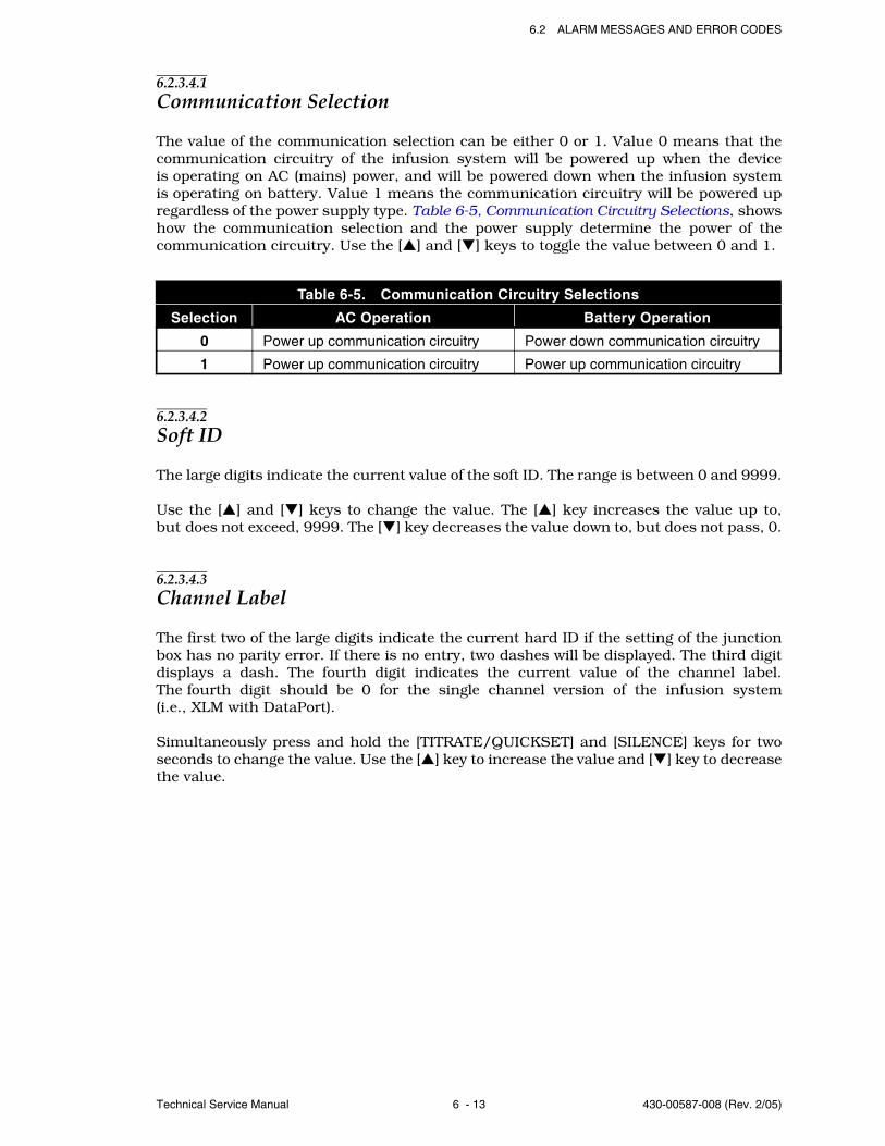
6.2 ALARM MESSAGES AND ERROR CODES
Technical Service Manual 6 - 13 430-00587-008 (Rev. 2/05)
6.2.3.4.1Communication Selection
The value of the communication selection can be either 0 or 1. Value 0 means that thecommunication circuitry of the infusion system will be powered up when the deviceis operating on AC (mains) power, and will be powered down when the infusion systemis operating on battery. Value 1 means the communication circuitry will be powered upregardless of the power supply type. Table 6-5, Communication Circuitry Selections, showshow the communication selection and the power supply determine the power of thecommunication circuitry. Use the [ ] and [ ] keys to toggle the value between 0 and 1.
6.2.3.4.2Soft ID
The large digits indicate the current value of the soft ID. The range is between 0 and 9999.
Use the [ ] and [ ] keys to change the value. The [ ] key increases the value up to,but does not exceed, 9999. The [ ] key decreases the value down to, but does not pass, 0.
6.2.3.4.3Channel Label
The first two of the large digits indicate the current hard ID if the setting of the junctionbox has no parity error. If there is no entry, two dashes will be displayed. The third digitdisplays a dash. The fourth digit indicates the current value of the channel label.The fourth digit should be 0 for the single channel version of the infusion system(i.e., XLM with DataPort).
Simultaneously press and hold the [TITRATE/QUICKSET] and [SILENCE] keys for twoseconds to change the value. Use the [ ] key to increase the value and [ ] key to decreasethe value.
Table 6-5. Communication Circuitry Selections
Selection AC Operation Battery Operation
0 Power up communication circuitry Power down communication circuitry
1 Power up communication circuitry Power up communication circuitry
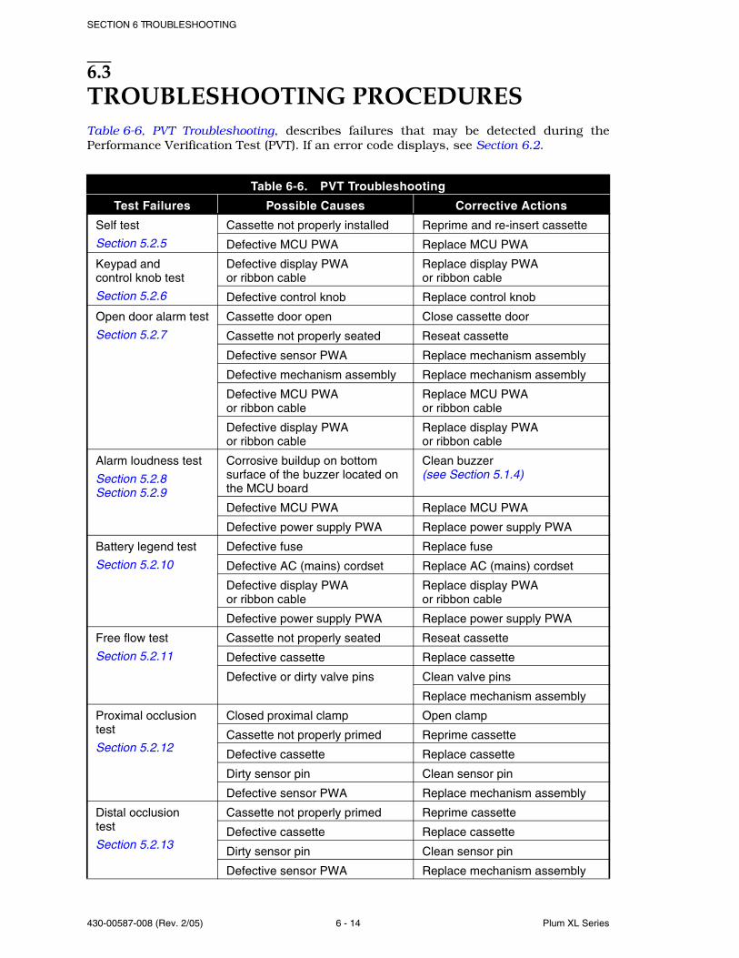
SECTION 6 TROUBLESHOOTING
430-00587-008 (Rev. 2/05) 6 - 14 Plum XL Series
6.3TROUBLESHOOTING PROCEDURESTable 6-6, PVT Troubleshooting, describes failures that may be detected during thePerformance Verification Test (PVT). If an error code displays, see Section 6.2.
Table 6-6. PVT Troubleshooting
Test Failures Possible Causes Corrective Actions
Self test
Section 5.2.5
Cassette not properly installed Reprime and re-insert cassette
Defective MCU PWA Replace MCU PWA
Keypad andcontrol knob test
Section 5.2.6
Defective display PWAor ribbon cable
Replace display PWAor ribbon cable
Defective control knob Replace control knob
Open door alarm test
Section 5.2.7
Cassette door open Close cassette door
Cassette not properly seated Reseat cassette
Defective sensor PWA Replace mechanism assembly
Defective mechanism assembly Replace mechanism assembly
Defective MCU PWAor ribbon cable
Replace MCU PWAor ribbon cable
Defective display PWAor ribbon cable
Replace display PWAor ribbon cable
Alarm loudness test
Section 5.2.8Section 5.2.9
Corrosive buildup on bottom surface of the buzzer located on the MCU board
Clean buzzer (see Section 5.1.4)
Defective MCU PWA Replace MCU PWA
Defective power supply PWA Replace power supply PWA
Battery legend test
Section 5.2.10
Defective fuse Replace fuse
Defective AC (mains) cordset Replace AC (mains) cordset
Defective display PWAor ribbon cable
Replace display PWAor ribbon cable
Defective power supply PWA Replace power supply PWA
Free flow test
Section 5.2.11
Cassette not properly seated Reseat cassette
Defective cassette Replace cassette
Defective or dirty valve pins Clean valve pins
Replace mechanism assembly
Proximal occlusion test
Section 5.2.12
Closed proximal clamp Open clamp
Cassette not properly primed Reprime cassette
Defective cassette Replace cassette
Dirty sensor pin Clean sensor pin
Defective sensor PWA Replace mechanism assembly
Distal occlusiontest
Section 5.2.13
Cassette not properly primed Reprime cassette
Defective cassette Replace cassette
Dirty sensor pin Clean sensor pin
Defective sensor PWA Replace mechanism assembly
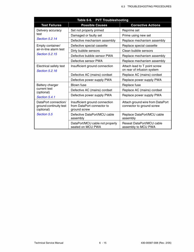
6.3 TROUBLESHOOTING PROCEDURES
Technical Service Manual 6 - 15 430-00587-008 (Rev. 2/05)
Delivery accuracy test
Section 5.2.14
Set not properly primed Reprime set
Damaged or faulty set Prime using new set
Defective mechanism assembly Replace mechanism assembly
Empty container/air-in-line alarm test
Section 5.2.15
Defective special cassette Replace special cassette
Dirty bubble sensors Clean bubble sensors
Defective bubble sensor PWA Replace mechanism assembly
Defective sensor PWA Replace mechanism assembly
Electrical safety test
Section 5.2.16
Insufficient ground connection Attach lead to T point screwon rear of infusion system
Defective AC (mains) cordset Replace AC (mains) cordset
Defective power supply PWA Replace power supply PWA
Battery charger current test(optional)
Section 5.4.1
Blown fuse Replace fuse
Defective AC (mains) cordset Replace AC (mains) cordset
Defective power supply PWA Replace power supply PWA
DataPort connection/ground continuity test(optional)
Section 5.5
Insufficient ground connection from DataPort connector to ground screw
Attach ground wire from DataPort connector to ground screw
Defective DataPort/MCU cable assembly
Replace DataPort/MCU cable assembly
DataPort/MCU cable not properly seated on MCU PWA
Reseat DataPort/MCU cable assembly to MCU PWA
Table 6-6. PVT Troubleshooting
Test Failures Possible Causes Corrective Actions

SECTION 6 TROUBLESHOOTING
430-00587-008 (Rev. 2/05) 6 - 16 Plum XL Series
This page intentionally left blank.

Technical Service Manual 7 - 1 430-00587-008 (Rev. 2/05)
Section 7
REPLACEABLE PARTS AND REPAIRSThis section itemizes all parts and subassemblies of the XL and XLM infusion systemsthat are repairable within the scope of this manual. In addition, this section detailsreplacement procedures for all listed parts.
7.1REPLACEABLE PARTSReplaceable parts for the infusion system are itemized in the spare parts price list and areidentified in Figure 9-1, Illustrated Parts Breakdown. Table 9-2, IPB for the Infusion System,identifies each infusion system part by an index number that correlates to Figure 9-1.
To request a copy of the current spare parts price list, contact Hospira (seeSection 6.1, Technical Assistance), or to view the catalog online, visit the website at:
www.hospiraparts.com
For convenient reference, insert a copy of the spare parts price list here.

SECTION 7 REPLACEABLE PARTS AND REPAIRS
430-00587-008 (Rev. 2/05) 7 - 2 Plum XL Series
This page intentionally left blank.
7.2 REPLACEMENT PROCEDURES
Technical Service Manual 7 - 3 430-00587-008 (Rev. 2/05)
7.2REPLACEMENT PROCEDURESThis section contains safety and equipment precautions, required tools and materials, andstep-by-step procedures for replacing parts in the infusion system. Unless otherwisestated, always perform the PVT after a replacement procedure.
7.2.1SAFETY AND EQUIPMENT PRECAUTIONS
Before opening the front enclosure of the infusion system, take all necessary precautionsfor working on high-voltage equipment.
CAUTION: Use proper ESD grounding techniques when handling components.Wear an antistatic wrist strap and use an ESD-protected workstation. Store PWAsin antistatic bags before placing them on any surface.
7.2.2REQUIRED TOOLS AND MATERIALS
The following tools and materials, or equivalents, are required for the replacementprocedures in this section. In addition, the beginning of each procedure lists tools andmaterials required for that specific procedure.
Set of nutdrivers (1/4, 3/16, and 5/16 inch)
Medium size flat blade screwdriver
No. 2 Phillips® screwdriver
Fuse puller
Wide-head pliers
Long needle nose pliers
Diagonal cutters
X-acto® knife (with square, round, and pointed blades)
Wood chisel, 3/8 inch
Mild solvent (such as isopropyl alcohol)
WARNING: POSSIBLE EXPLOSION HAZARD EXISTS IF THE INFUSIONSYSTEM IS SERVICED OR REPAIRED IN THE PRESENCE OFFLAMMABLE ANESTHETICS.
WARNING: UNLESS OTHERWISE INDICATED, DISCONNECT THEINFUSION SYSTEM FROM AC POWER BEFORE PERFORMINGANY REPLACEMENT PROCEDURE.
SECTION 7 REPLACEABLE PARTS AND REPAIRS
430-00587-008 (Rev. 2/05) 7 - 4 Plum XL Series
7.2.3RUBBER FOOT PAD REPLACEMENT
Recommended tools and materials for this procedure are a 3/8 inch wood chisel or anX-acto knife and mild solvent.
The replacement part for this procedure is:
Foot Pad, Rubber
To replace the rubber foot pads, refer to Figure 7-1, Bottom View of the Infusion System,then proceed as follows:
1. Turn the control knob to OFF/CHARGE.
2. Disconnect the infusion system from AC (mains) power.
3. Set the infusion system on its back to access the foot pads.
4. Using a 3/8 inch wood chisel or an X-acto knife, remove the rubber foot pad andscrape the enclosure recess to remove adhesive residue.
Note: Each adhesive-backed rubber foot pad is bonded in its recess. Do notdamage the recess.
5. Using a mild solvent, clean the enclosure recess.
6. Remove the protective backing from the self-adhesive surface on the replacementrubber foot pad and bond the foot pad in place.
7. After approximately five minutes, verify the foot pad is secure.
8. Connect the infusion system to AC (mains) power.
Replacement of a rubber foot pad is a routine maintenance procedure and no verificationprocedure is normally required. However, if the infusion system may have been damagedduring this procedure, perform the PVT in Section 5.2.
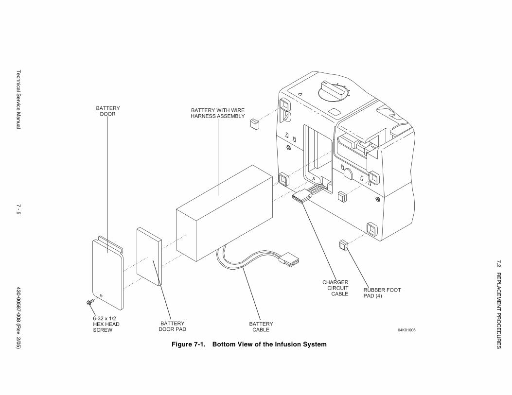
7.2R
EP
LAC
EM
EN
T P
RO
CE
DU
RE
S
Technical S
ervice Manual
7 - 5430-00587-008 (R
ev. 2/05) Figure 7-1. Bottom View of the Infusion System
BATTERY
DOOR
6-32 x 1/2
HEX HEAD
SCREW
BATTERY
DOOR PAD
BATTERY
CABLE
BATTERY WITH WIRE
HARNESS ASSEMBLY
CHARGER
CIRCUIT
CABLERUBBER FOOT
PAD (4)
04K01006
SECTION 7 REPLACEABLE PARTS AND REPAIRS
430-00587-008 (Rev. 2/05) 7 - 6 Plum XL Series
7.2.4BATTERY WITH WIRE HARNESS ASSEMBLY, BATTERY DOOR, AND BATTERY DOOR PAD REPLACEMENT
Recommended tools and materials for this procedure are a medium size flat bladescrewdriver, an X-acto knife, and mild solvent.
The replacement parts for this procedure are:
Screw, 6-32 x 1/2, Hex Head, SlottedAssembly, Battery, with Wire HarnessPad, Door, BatteryDoor, Battery
To replace the battery, battery door, and battery door pad, refer to Figure 7-1, then proceedas follows:
1. Turn the control knob to OFF/CHARGE.
2. Disconnect the infusion system from AC (mains) power.
3. Set the infusion system on its back to access the bottom.
4. Using a medium size flat blade screwdriver, remove the hex head screw securingthe battery door to the infusion system. Remove the battery door and replace it ifnecessary.
5. Inspect the battery door pad for damage. If the pad is damaged, remove it using anX-acto knife and mild solvent. Dry the battery door thoroughly, and install a newbattery door pad on the battery door.
6. Disconnect the battery cable from the charger circuit cable. Pull the battery cablewires and connector outside the enclosure. Remove the battery.
7. Connect the replacement battery cable to the charger circuit cable.
Note: The cable connectors are keyed so that cables cannot be connectedincorrectly.
8. Insert the replacement battery into the enclosure, confirming that the battery cableis not pinched between the battery and the enclosure.
9. Using a medium size flat blade screwdriver, replace and tighten the hex head screwto secure the battery door to the infusion system.
10. Connect the infusion system to AC (mains) power.
To verify successful battery, battery door, and battery door pad replacement, perform thePVT in Section 5.2.
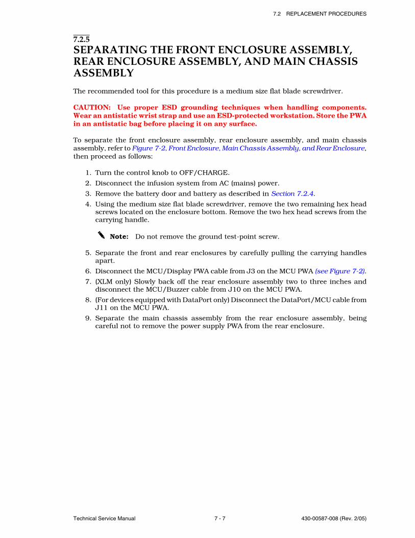
7.2 REPLACEMENT PROCEDURES
Technical Service Manual 7 - 7 430-00587-008 (Rev. 2/05)
7.2.5SEPARATING THE FRONT ENCLOSURE ASSEMBLY, REAR ENCLOSURE ASSEMBLY, AND MAIN CHASSIS ASSEMBLY
The recommended tool for this procedure is a medium size flat blade screwdriver.
CAUTION: Use proper ESD grounding techniques when handling components.Wear an antistatic wrist strap and use an ESD-protected workstation. Store the PWAin an antistatic bag before placing it on any surface.
To separate the front enclosure assembly, rear enclosure assembly, and main chassisassembly, refer to Figure 7-2, Front Enclosure, Main Chassis Assembly, and Rear Enclosure,then proceed as follows:
1. Turn the control knob to OFF/CHARGE.
2. Disconnect the infusion system from AC (mains) power.
3. Remove the battery door and battery as described in Section 7.2.4.
4. Using the medium size flat blade screwdriver, remove the two remaining hex headscrews located on the enclosure bottom. Remove the two hex head screws from thecarrying handle.
Note: Do not remove the ground test-point screw.
5. Separate the front and rear enclosures by carefully pulling the carrying handlesapart.
6. Disconnect the MCU/Display PWA cable from J3 on the MCU PWA (see Figure 7-2).
7. (XLM only) Slowly back off the rear enclosure assembly two to three inches anddisconnect the MCU/Buzzer cable from J10 on the MCU PWA.
8. (For devices equipped with DataPort only) Disconnect the DataPort/MCU cable fromJ11 on the MCU PWA.
9. Separate the main chassis assembly from the rear enclosure assembly, beingcareful not to remove the power supply PWA from the rear enclosure.
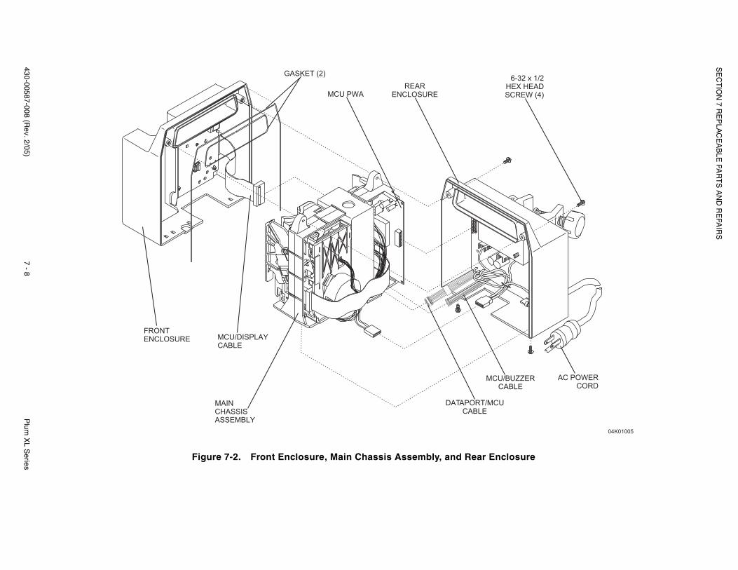
SE
CT
ION
7 RE
PLA
CE
AB
LE PA
RT
S A
ND
RE
PAIR
S
430-00587-008 (Rev. 2/05)
7 - 8P
lum X
L Series
Figure 7-2. Front Enclosure, Main Chassis Assembly, and Rear Enclosure
MCU/DISPLAY
CABLE
FRONT
ENCLOSURE
MAIN
CHASSIS
ASSEMBLY
DATAPORT/MCU
CABLE
MCU/BUZZER
CABLE
AC POWER
CORD
GASKET (2)
MCU PWA
REAR
ENCLOSURE
6-32 x 1/2
HEX HEAD
SCREW (4)
04K01005
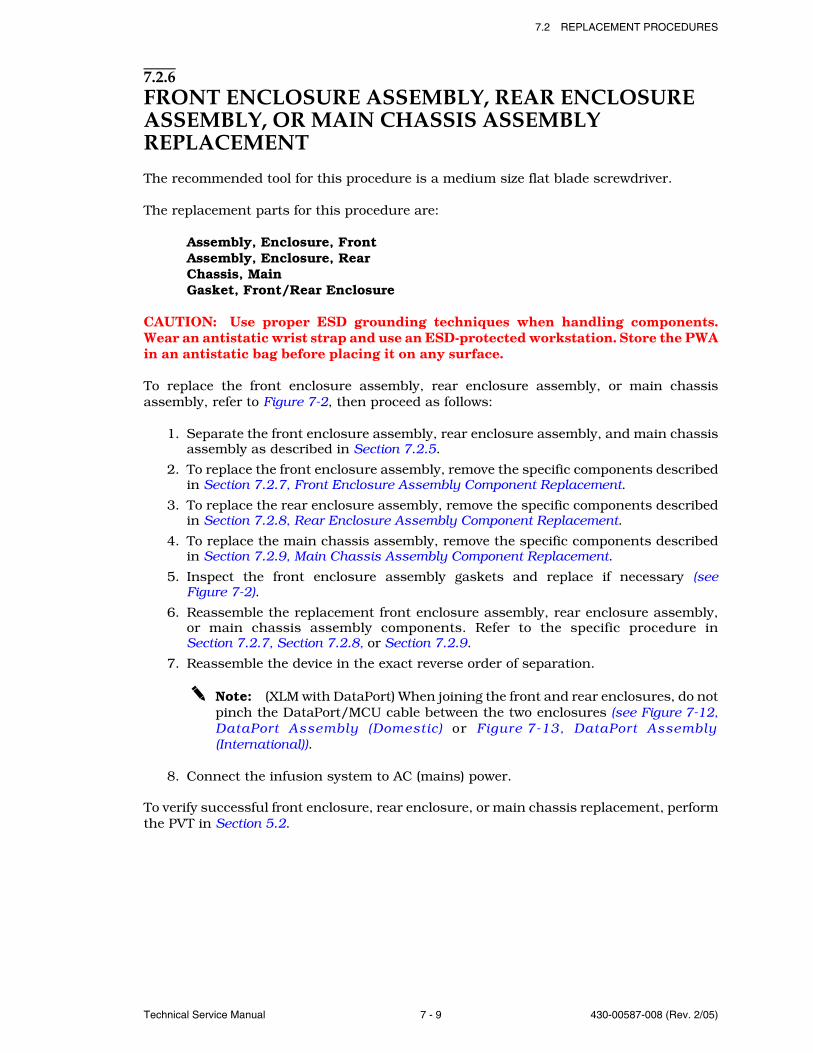
7.2 REPLACEMENT PROCEDURES
Technical Service Manual 7 - 9 430-00587-008 (Rev. 2/05)
7.2.6FRONT ENCLOSURE ASSEMBLY, REAR ENCLOSURE ASSEMBLY, OR MAIN CHASSIS ASSEMBLY REPLACEMENT
The recommended tool for this procedure is a medium size flat blade screwdriver.
The replacement parts for this procedure are:
Assembly, Enclosure, FrontAssembly, Enclosure, RearChassis, MainGasket, Front/Rear Enclosure
CAUTION: Use proper ESD grounding techniques when handling components.Wear an antistatic wrist strap and use an ESD-protected workstation. Store the PWAin an antistatic bag before placing it on any surface.
To replace the front enclosure assembly, rear enclosure assembly, or main chassisassembly, refer to Figure 7-2, then proceed as follows:
1. Separate the front enclosure assembly, rear enclosure assembly, and main chassisassembly as described in Section 7.2.5.
2. To replace the front enclosure assembly, remove the specific components describedin Section 7.2.7, Front Enclosure Assembly Component Replacement.
3. To replace the rear enclosure assembly, remove the specific components describedin Section 7.2.8, Rear Enclosure Assembly Component Replacement.
4. To replace the main chassis assembly, remove the specific components describedin Section 7.2.9, Main Chassis Assembly Component Replacement.
5. Inspect the front enclosure assembly gaskets and replace if necessary (seeFigure 7-2).
6. Reassemble the replacement front enclosure assembly, rear enclosure assembly,or main chassis assembly components. Refer to the specific procedure inSection 7.2.7, Section 7.2.8, or Section 7.2.9.
7. Reassemble the device in the exact reverse order of separation.
Note: (XLM with DataPort) When joining the front and rear enclosures, do notpinch the DataPort/MCU cable between the two enclosures (see Figure 7-12,DataPort Assembly (Domestic) or Figure 7-13, DataPort Assembly(International)).
8. Connect the infusion system to AC (mains) power.
To verify successful front enclosure, rear enclosure, or main chassis replacement, performthe PVT in Section 5.2.

SECTION 7 REPLACEABLE PARTS AND REPAIRS
430-00587-008 (Rev. 2/05) 7 - 10 Plum XL Series
7.2.7FRONT ENCLOSURE ASSEMBLY COMPONENT REPLACEMENT
Front enclosure assembly component replacement includes the replacement of thefollowing:
Display PWA and MCU/display cable
Switch-activated front panel keys
Control knob, knob detent, washer, and snap retainer
Front panel label
To replace the front enclosure assembly components, refer to either Figure 7-3, DisplayPWA and MCU/Display Cable, or Figure 7-4, Front Enclosure Assembly Components, thenproceed as detailed in the following sections.
Figure 7-3. Display PWA and MCU/Display Cable
FRONT
ENCLOSURE
ASSEMBLY
DISPLAY PWA
4-24 x 3/8
B/POINT
SCREW
MCU/DISPLAY
CABLE
TAB RETAINER (4)
04K01007
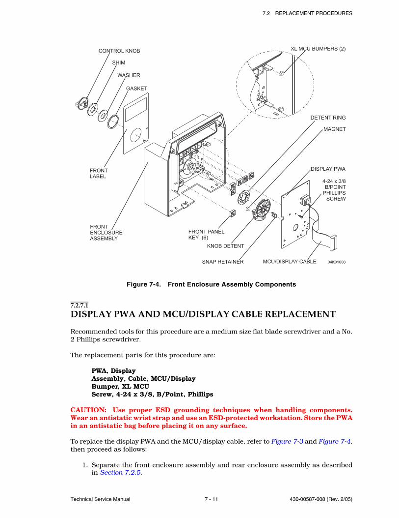
7.2 REPLACEMENT PROCEDURES
Technical Service Manual 7 - 11 430-00587-008 (Rev. 2/05)
Figure 7-4. Front Enclosure Assembly Components
7.2.7.1DISPLAY PWA AND MCU/DISPLAY CABLE REPLACEMENT
Recommended tools for this procedure are a medium size flat blade screwdriver and a No.2 Phillips screwdriver.
The replacement parts for this procedure are:
PWA, DisplayAssembly, Cable, MCU/DisplayBumper, XL MCUScrew, 4-24 x 3/8, B/Point, Phillips
CAUTION: Use proper ESD grounding techniques when handling components.Wear an antistatic wrist strap and use an ESD-protected workstation. Store the PWAin an antistatic bag before placing it on any surface.
To replace the display PWA and the MCU/display cable, refer to Figure 7-3 and Figure 7-4,then proceed as follows:
1. Separate the front enclosure assembly and rear enclosure assembly as describedin Section 7.2.5.
04K01008
CONTROL KNOB
WASHER
GASKET
FRONT
LABEL
FRONT
ENCLOSURE
ASSEMBLY
FRONT PANEL
KEY (6)
KNOB DETENT
SNAP RETAINER
DETENT RING
DISPLAY PWA
MCU/DISPLAY CABLE
MAGNET
4-24 x 3/8
B/POINT
PHILLIPS
SCREW
XL MCU BUMPERS (2)
SHIM
SECTION 7 REPLACEABLE PARTS AND REPAIRS
430-00587-008 (Rev. 2/05) 7 - 12 Plum XL Series
2. Place the front enclosure assembly face down.
3. Remove and replace the two XL MCU Bumpers.
4. Using a No. 2 Phillips screwdriver, remove the Phillips screw securing the displayPWA to the control knob assembly.
5. Disengage the four tab retainers securing the display PWA to the front enclosureassembly. Remove the display PWA from the front enclosure assembly.
6. Disconnect the MCU/display cable from the display PWA. Replace the MCU/displaycable if it is defective or damaged.
7. Install the replacement display PWA in the exact reverse order of removal.
8. Reassemble the device in the exact reverse order of disassembly.
Note: (XLM with DataPort) When joining the front and rear enclosures, do notpinch the DataPort/MCU cable between the two enclosures.
9. Connect the infusion system to AC (mains) power.
To verify successful display PWA and MCU/display cable replacement, perform the PVTin Section 5.2.
7.2.7.2FRONT PANEL KEY REPLACEMENT
Recommended tools for this procedure are a medium size flat blade screwdriver and No.2 Phillips screwdriver.
The replacement part for this procedure is:
Key, Front Panel, Switch Activated
CAUTION: Use proper ESD grounding techniques when handling components.Wear an antistatic wrist strap and use an ESD-protected workstation. Store the PWAin an antistatic bag before placing it on any surface.
To replace the front panel keys, refer to Figure 7-4, then proceed as follows:
1. Separate the front enclosure assembly and rear enclosure assembly as describedin Section 7.2.5.
2. Remove the display PWA as described in Section 7.2.7.1.
3. Remove the front panel keys from the key recesses and install replacements (seeFigure 7-4).
4. Reassemble the device in the exact reverse order of disassembly.
Note: (XLM with DataPort) When joining the front and rear enclosures, do notpinch the DataPort/MCU cable between the two enclosures.
5. Connect the infusion system to AC (mains) power.
To verify successful front panel key replacement, perform the PVT in Section 5.2.
7.2 REPLACEMENT PROCEDURES
Technical Service Manual 7 - 13 430-00587-008 (Rev. 2/05)
7.2.7.3CONTROL KNOB, KNOB DETENT, WASHER, GASKET, SNAP RETAINER, AND DETENT RING REPLACEMENT
Recommended tools for this procedure are a small flat blade screwdriver, a medium sizeflat blade screwdriver, a No. 2 Phillips screwdriver, and long needle nose pliers.
The replacement parts for this procedure are:
Retainer, Snap, KnobKnob, ControlDetent, KnobWasher, KnobGasket, KnobRing, DetentShimMagnet
CAUTION: Use proper ESD grounding techniques when handling components.Wear an antistatic wrist strap and use an ESD-protected workstation. Store the PWAin an antistatic bag before placing it on any surface.
To replace the control knob, knob detent, washer, gasket, detent ring, and snap retainer,refer to Figure 7-4, then proceed as follows:
1. Separate the front enclosure assembly and rear enclosure assembly as describedin Section 7.2.5.
2. Remove the display PWA as described in Section 7.2.7.1.
3. Remove the front panel keys as described in Section 7.2.7.2.
4. Using long needle nose pliers, carefully remove the snap retainer.
5. Remove the control knob, knob detent, shim, washer, gasket, and detent ring.
6. Inspect the magnet on the knob detent. If the magnet appears damaged, carefullyremove it using the small flat blade screwdriver. Install the replacement, assuringthat the dot on the magnet is facing up.
7. Install the replacement control knob, washer, and gasket.
- Fit the gasket into the circular recess on the front side of the front enclosure.
- Install the washer on the control knob.
- Install the shim on the control knob.
- Place the control knob through the hole in the front enclosure.
- Turn the control knob to OFF/CHARGE.
8. Place the front enclosure assembly face down. Place the detent ring on the fourpins, centered on the control knob. Assure that the raised bumps on the detentring are facing up.
9. Using the snap retainer, secure the knob detent on the control knob retainer clipsand splines. Press the snap retainer firmly until it is secure.
Note: When the control knob is at OFF/CHARGE, the knob detent ispositioned on the detent ring as shown in Figure 7-4.
10. Verify that the control knob rotates fully.
11. Reassemble the device in the exact reverse order of disassembly.
SECTION 7 REPLACEABLE PARTS AND REPAIRS
430-00587-008 (Rev. 2/05) 7 - 14 Plum XL Series
Note: (XLM with DataPort) When joining the front and rear enclosures, do notpinch the DataPort/MCU cable between the two enclosures.
12. Connect the infusion system to AC (mains) power.
To verify successful control knob, knob detent, washer, and snap retainer replacement,perform the PVT in Section 5.2.
7.2.7.4FRONT PANEL LABEL REPLACEMENT
Recommended tools and materials for this procedure are an X-acto knife, long needle nosepliers, and mild solvent.
The replacement part for this procedure is:
Label, Front Panel
To replace the front panel label, refer to Figure 7-4, then proceed as follows:
1. Turn the control knob to OFF/CHARGE.
2. Disconnect the infusion system from AC (mains) power.
3. Using an X-acto knife, remove the front panel label from the front panel enclosure.
4. Using a mild solvent, remove adhesive residue from the front panel assembly recess.
5. Remove the adhesive backing from the replacement front panel label and press thelabel into place on the front enclosure assembly.
Replacement of the front panel label is a routine maintenance procedure and noverification procedure is normally required. However, if the infusion system may have beendamaged during this procedure, perform the PVT in Section 5.2.
7.2.8REAR ENCLOSURE ASSEMBLY COMPONENT REPLACEMENTRear enclosure assembly component replacement includes the replacement of thefollowing:
Fuses
Power supply PWA
Velcro retainer strap
AC (mains) power cord, and strain relief bushing
AC (mains) power cord (International)
AC receptacle, EMI shield, and equipotential post
LifeCare AC receptacle, bracket, gasket, seal, and equipotential post
DataPort/MCU cable assembly
LifeCare DataPort/MCU cable assembly
Pole clamp extrusion, knob, backing plate, and adhesive-backed insulator
Pole clamp shaft/knob assembly and the pole clamp shaft tip
Buzzer PWA and MCU/buzzer cable
7.2 REPLACEMENT PROCEDURES
Technical Service Manual 7 - 15 430-00587-008 (Rev. 2/05)
To replace the rear enclosure assembly components, proceed as detailed in the followingsections.
7.2.8.1FUSE REPLACEMENT
Recommended tools for this procedure are a medium size flat blade screwdriver and a fusepuller.
The replacement part for this procedure is:
Fuse, 0.5A, 250V, Slo-Blo, 5 x 20 mmCover, Fuse 5 x 20 mm
To replace the fuse, refer to Figure 7-5, Fuse Replacement (115 VAC) or Figure 7-6, FuseReplacement (220 VAC), then proceed as follows:
1. Separate the front enclosure assembly and rear enclosure assembly as describedin Section 7.2.5.
2. Remove the two plastic fuse covers. Using the fuse puller, remove the two fuses onthe power supply PWA and install replacements.
CAUTION: Confirm replacement fuse rating is identical to fuse ratingindicated on the power supply PWA or equipment damage may occur.
3. Reassemble the device in the exact reverse order of disassembly.
Note: (XLM with DataPort) When joining the front and rear enclosures, do notpinch the DataPort/MCU cable between the two enclosures.
4. Connect the infusion system to AC (mains) power.
To verify successful fuse replacement, perform the PVT in Section 5.2.
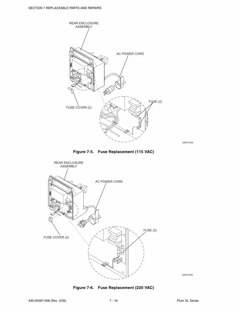
SECTION 7 REPLACEABLE PARTS AND REPAIRS
430-00587-008 (Rev. 2/05) 7 - 16 Plum XL Series
Figure 7-5. Fuse Replacement (115 VAC)
Figure 7-6. Fuse Replacement (220 VAC)
FUSE COVER (2)
FUSE (2)
REAR ENCLOSURE
ASSEMBLY
04K01034
AC POWER CORD
FUSE COVER (2)
FUSE (2)
REAR ENCLOSURE
ASSEMBLY
04K01035
AC POWER CORD
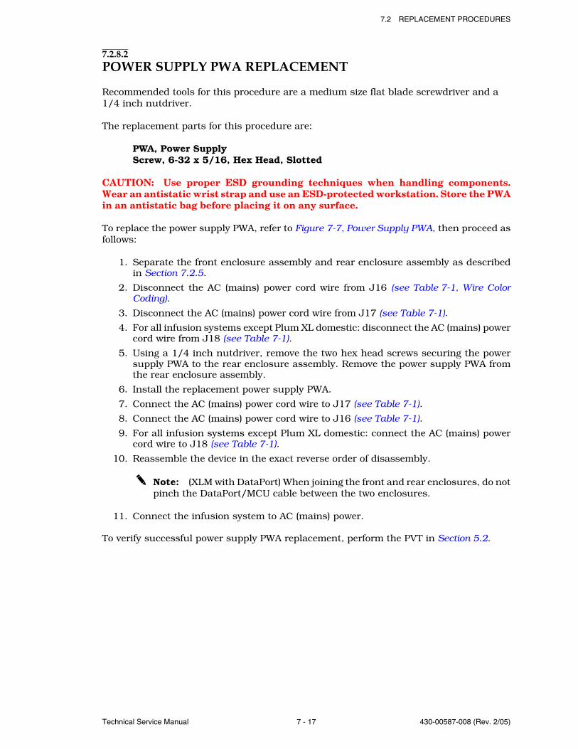
7.2 REPLACEMENT PROCEDURES
Technical Service Manual 7 - 17 430-00587-008 (Rev. 2/05)
7.2.8.2POWER SUPPLY PWA REPLACEMENT
Recommended tools for this procedure are a medium size flat blade screwdriver and a 1/4 inch nutdriver.
The replacement parts for this procedure are:
PWA, Power SupplyScrew, 6-32 x 5/16, Hex Head, Slotted
CAUTION: Use proper ESD grounding techniques when handling components.Wear an antistatic wrist strap and use an ESD-protected workstation. Store the PWAin an antistatic bag before placing it on any surface.
To replace the power supply PWA, refer to Figure 7-7, Power Supply PWA, then proceed asfollows:
1. Separate the front enclosure assembly and rear enclosure assembly as describedin Section 7.2.5.
2. Disconnect the AC (mains) power cord wire from J16 (see Table 7-1, Wire ColorCoding).
3. Disconnect the AC (mains) power cord wire from J17 (see Table 7-1).
4. For all infusion systems except Plum XL domestic: disconnect the AC (mains) powercord wire from J18 (see Table 7-1).
5. Using a 1/4 inch nutdriver, remove the two hex head screws securing the powersupply PWA to the rear enclosure assembly. Remove the power supply PWA fromthe rear enclosure assembly.
6. Install the replacement power supply PWA.
7. Connect the AC (mains) power cord wire to J17 (see Table 7-1).
8. Connect the AC (mains) power cord wire to J16 (see Table 7-1).
9. For all infusion systems except Plum XL domestic: connect the AC (mains) powercord wire to J18 (see Table 7-1).
10. Reassemble the device in the exact reverse order of disassembly.
Note: (XLM with DataPort) When joining the front and rear enclosures, do notpinch the DataPort/MCU cable between the two enclosures.
11. Connect the infusion system to AC (mains) power.
To verify successful power supply PWA replacement, perform the PVT in Section 5.2.
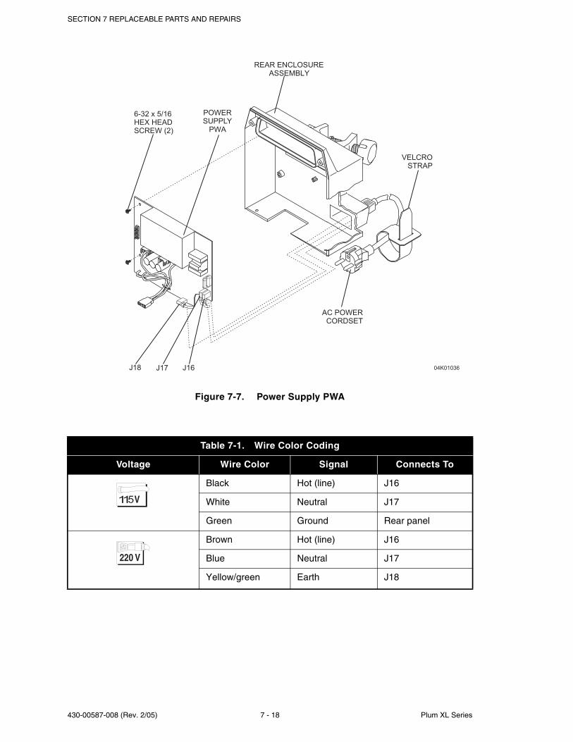
SECTION 7 REPLACEABLE PARTS AND REPAIRS
430-00587-008 (Rev. 2/05) 7 - 18 Plum XL Series
Figure 7-7. Power Supply PWA
Table 7-1. Wire Color Coding
Voltage Wire Color Signal Connects To
Black Hot (line) J16
White Neutral J17
Green Ground Rear panel
Brown Hot (line) J16
Blue Neutral J17
Yellow/green Earth J18
6-32 x 5/16
HEX HEAD
SCREW (2)
POWER
SUPPLY
PWA
AC POWER
CORDSET
VELCRO
STRAP
04K01036
REAR ENCLOSURE
ASSEMBLY
J16J17J18
7.2 REPLACEMENT PROCEDURES
Technical Service Manual 7 - 19 430-00587-008 (Rev. 2/05)
7.2.8.3VELCRO RETAINER STRAP REPLACEMENT
No tools are required for this procedure.
The replacement part for this procedure is:
Strap, Velcro, 1.75 in x 10 in, Black
To replace the Velcro retainer strap, remove the strap from the power cord and install thereplacement (see Figure 7-7).
Replacement of the Velcro retainer strap is a routine maintenance procedure and noverification procedure is normally required. However, if the infusion system may have beendamaged during the Velcro retainer strap replacement, perform the PVT in Section 5.2.
7.2.8.4AC (MAINS) POWER CORD AND STRAIN RELIEF BUSHING REPLACEMENT
Recommended tools for this procedure are a medium size flat blade screwdriver,a 1/4 inch nutdriver, and pliers.
The replacement parts for this procedure are:
Cordset, AC Power, Hospital GradeStrain Relief, Nylon, BlackNut, 6-32, KEP, with WasherWasher, Flat, #6Screw, 6-32 x 3/4, Hex Head, Slotted, w/Washer (XL)Screw, 6-32 x 1, Hex Head, Slotted, w/Washer (XLM)
CAUTION: Use proper ESD grounding techniques when handling components.Wear an antistatic wrist strap and use an ESD-protected workstation. Store the PWAin an antistatic bag before placing it on any surface.
To replace the AC (mains) power cord, and strain relief bushing, refer to Figure 7-8, ACPower Cord (115 VAC - Plum XL) or Figure 7-9, AC Power Cord (115 VAC - Plum XLM), thenproceed as follows:
1. Separate the front enclosure assembly and rear enclosure assembly as describedin Section 7.2.5.
2. Using a 1/4 inch nutdriver, remove the two hex head nuts from the hex head groundscrew.
3. Disconnect the green ground wire from the ground screw.
4. Disconnect the AC (mains) power cord wire from J16 (see Table 7-1, Wire ColorCoding).
5. Disconnect the AC (mains) power cord wire from J17 (see Table 7-1).
6. Use the pliers to remove the strain relief bushing.
7. Pull the AC (mains) power cord through the mounting hole in the rear enclosureassembly.
8. Install the replacement AC (mains) power cord in the exact reverse order of removal.
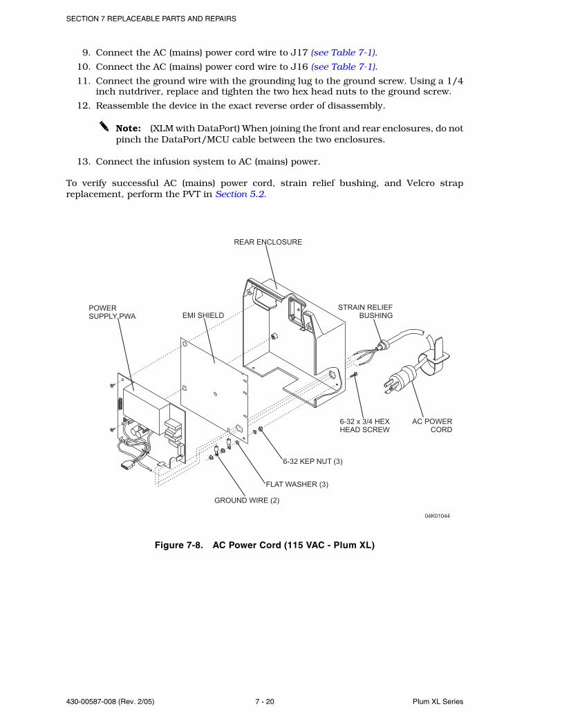
SECTION 7 REPLACEABLE PARTS AND REPAIRS
430-00587-008 (Rev. 2/05) 7 - 20 Plum XL Series
9. Connect the AC (mains) power cord wire to J17 (see Table 7-1).
10. Connect the AC (mains) power cord wire to J16 (see Table 7-1).
11. Connect the ground wire with the grounding lug to the ground screw. Using a 1/4inch nutdriver, replace and tighten the two hex head nuts to the ground screw.
12. Reassemble the device in the exact reverse order of disassembly.
Note: (XLM with DataPort) When joining the front and rear enclosures, do notpinch the DataPort/MCU cable between the two enclosures.
13. Connect the infusion system to AC (mains) power.
To verify successful AC (mains) power cord, strain relief bushing, and Velcro strapreplacement, perform the PVT in Section 5.2.
Figure 7-8. AC Power Cord (115 VAC - Plum XL)
REAR ENCLOSURE
AC POWER
CORD
EMI SHIELD
POWER
SUPPLY PWA
04K01044
STRAIN RELIEF
BUSHING
6-32 KEP NUT (3)
FLAT WASHER (3)
GROUND WIRE (2)
6-32 x 3/4 HEX
HEAD SCREW
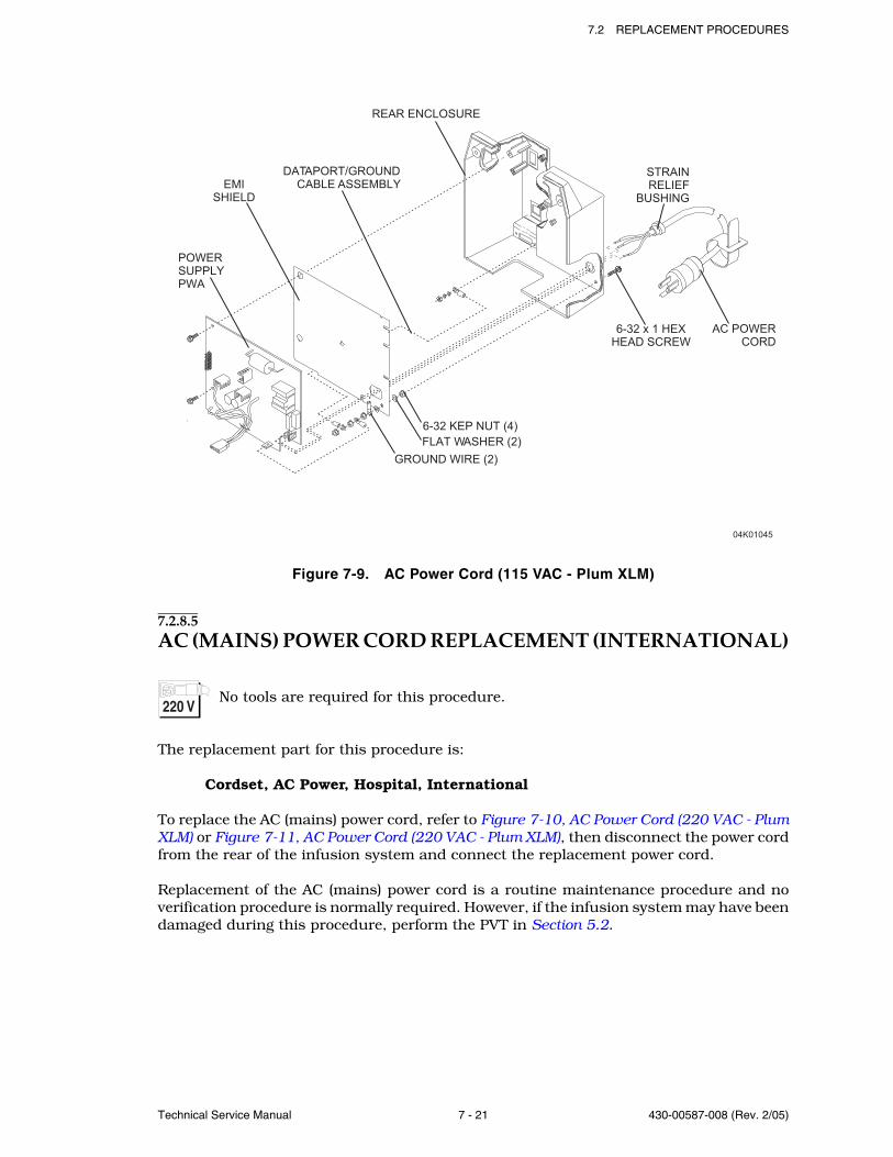
7.2 REPLACEMENT PROCEDURES
Technical Service Manual 7 - 21 430-00587-008 (Rev. 2/05)
Figure 7-9. AC Power Cord (115 VAC - Plum XLM)
7.2.8.5AC (MAINS) POWER CORD REPLACEMENT (INTERNATIONAL)
No tools are required for this procedure.
The replacement part for this procedure is:
Cordset, AC Power, Hospital, International
To replace the AC (mains) power cord, refer to Figure 7-10, AC Power Cord (220 VAC - PlumXLM) or Figure 7-11, AC Power Cord (220 VAC - Plum XLM), then disconnect the power cordfrom the rear of the infusion system and connect the replacement power cord.
Replacement of the AC (mains) power cord is a routine maintenance procedure and noverification procedure is normally required. However, if the infusion system may have beendamaged during this procedure, perform the PVT in Section 5.2.
EMI
SHIELD
REAR ENCLOSURE
AC POWER
CORD
DATAPORT/GROUND
CABLE ASSEMBLY
04K01045
STRAIN
RELIEF
BUSHING
POWER
SUPPLY
PWA
FLAT WASHER (2)
6-32 KEP NUT (4)
GROUND WIRE (2)
6-32 x 1 HEX
HEAD SCREW
SECTION 7 REPLACEABLE PARTS AND REPAIRS
430-00587-008 (Rev. 2/05) 7 - 22 Plum XL Series
7.2.8.6AC RECEPTACLE, EMI SHIELD, AND EQUIPOTENTIAL POST REPLACEMENT
Recommended tool for this procedure is a 6 mm nutdriver.
The replacement parts for this procedure are:
Receptacle, AC ConnectionPost, EquipotentialShield, EMINut, Hex, 6mmWasher, LockWasher, FlatWasher, Flat, 1/4 inch
CAUTION: Use proper ESD grounding techniques when handling components.Wear an antistatic wrist strap and use an ESD-protected workstation. Store the PWAin an antistatic bag before placing it on any surface.
To replace the AC connection receptacle and equipotential post, refer to Figure 7-10, thenproceed as follows:
1. Separate the front enclosure assembly and rear enclosure assembly as describedin Section 7.2.5.
2. Remove the power supply PWA as described in Section 7.2.8.2.
3. Remove the hex nut and two washers holding the EMI shield to the equipotentialpost. Replace the EMI shield if necessary.
4. Remove the hex nut, three washers and three ground wires, then the remaininghex nut and washers from the equipotential post (see Figure 7-10).
5. Remove the equipotential post and replace if necessary.
6. Remove the AC receptacle by pulling it through the rear enclosure. Install areplacement if necessary.
7. Reassemble the device in the exact reverse order of disassembly.
Note: (XLM with DataPort) When joining the front and rear enclosures, do notpinch the DataPort/MCU cable between the two enclosures.
8. Connect the infusion system to AC (mains) power.
To verify sucessful AC receptacle, EMI shield, and equipotential post replacement, performthe PVT in Section 5.2.
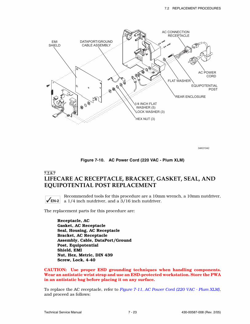
7.2 REPLACEMENT PROCEDURES
Technical Service Manual 7 - 23 430-00587-008 (Rev. 2/05)
Figure 7-10. AC Power Cord (220 VAC - Plum XLM)
7.2.8.7LIFECARE AC RECEPTACLE, BRACKET, GASKET, SEAL, AND EQUIPOTENTIAL POST REPLACEMENT
Recommended tools for this procedure are a 10mm wrench, a 10mm nutdriver,a 1/4 inch nutdriver, and a 3/16 inch nutdriver.
The replacement parts for this procedure are:
Receptacle, ACGasket, AC ReceptacleSeal, Housing, AC ReceptacleBracket, AC ReceptacleAssembly, Cable, DataPort/GroundPost, EquipotentialShield, EMINut, Hex, Metric, DIN 439Screw, Lock, 4-40
CAUTION: Use proper ESD grounding techniques when handling components.Wear an antistatic wrist strap and use an ESD-protected workstation. Store the PWAin an antistatic bag before placing it on any surface.
To replace the AC receptacle, refer to Figure 7-11, AC Power Cord (220 VAC - Plum XLM),and proceed as follows:
EN-2
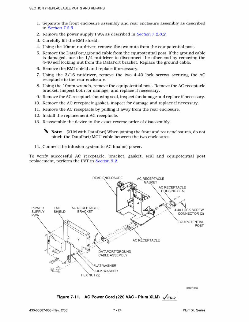
SECTION 7 REPLACEABLE PARTS AND REPAIRS
430-00587-008 (Rev. 2/05) 7 - 24 Plum XL Series
1. Separate the front enclosure assembly and rear enclosure assembly as describedin Section 7.2.5.
2. Remove the power supply PWA as described in Section 7.2.8.2.
3. Carefully lift the EMI shield.
4. Using the 10mm nutdriver, remove the two nuts from the equipotential post.
5. Remove the DataPort/ground cable from the equipotential post. If the ground cableis damaged, use the 1/4 nutdriver to disconnect the other end by removing the4-40 self locking nut from the DataPort bracket. Replace the ground cable.
6. Remove the EMI shield and replace if necessary.
7. Using the 3/16 nutdriver, remove the two 4-40 lock screws securing the ACreceptacle to the rear enclosure.
8. Using the 10mm wrench, remove the equipotential post. Remove the AC receptaclebracket. Inspect both for damage, and replace if necessary.
9. Remove the AC receptacle housing seal, inspect for damage and replace if necessary.
10. Remove the AC receptacle gasket, inspect for damage and replace if necessary.
11. Remove the AC receptacle by pulling it away from the rear enclosure.
12. Install the replacement AC receptacle.
13. Reassemble the device in the exact reverse order of disassembly.
Note: (XLM with DataPort) When joining the front and rear enclosures, do notpinch the DataPort/MCU cable between the two enclosures.
14. Connect the infusion system to AC (mains) power.
To verify successful AC receptacle, bracket, gasket, seal and equipotential postreplacement, perform the PVT in Section 5.2.
Figure 7-11. AC Power Cord (220 VAC - Plum XLM)
POWER
SUPPLY
PWA
AC RECEPTACLE
BRACKET
REAR ENCLOSURE
AC RECEPTACLE
AC RECEPTACLE
GASKET
AC RECEPTACLE
HOUSING SEAL
4-40 LOCK SCREW
CONNECTOR (2)
EQUIPOTENTIAL
POST
HEX NUT (2)
EMI
SHIELD
04K01043
DATAPORT/GROUND
CABLE ASSEMBLY
FLAT WASHER
LOCK WASHER
EN-2
7.2 REPLACEMENT PROCEDURES
Technical Service Manual 7 - 25 430-00587-008 (Rev. 2/05)
7.2.8.8DATAPORT/MCU CABLE ASSEMBLY REPLACEMENT (XLM WITH DATAPORT)
Recommended tools for this procedure are a medium size flat blade screwdriver, a 1/4inch nutdriver, and a 3/16 inch nutdriver.
The replacement parts for this procedure are:
EMI ShieldKit, Lock Screw Connector, 4-40Kit, Lock Screw, 4-40 x 5/16Assembly, Cable, DataPort/MCUAssembly, Cable, DataPort/Ground
CAUTION: Use proper ESD grounding techniques when handling components.Wear an antistatic wrist strap and use an ESD-protected workstation. Store the PWAin an antistatic bag before placing it on any surface.
Note: Do not connect DataPort when infusing.
To replace the DataPort/MCU cable assembly, refer to Figure 7-12, DataPort Assembly(Domestic), and proceed as follows:
1. Separate the front enclosure assembly and rear enclosure assembly as describedin Section 7.2.5.
2. Remove the power supply PWA as described in Section 7.2.8.2.
3. Remove the EMI shield.
4. Using the 3/16 inch nutdriver, remove the DataPort ground cable nut from insidethe rear case.
5. Remove the two lock screws on the outside of the rear case, disconnecting theDataPort ground cable.
6. Remove the DataPort/MCU cable assembly through the rear case, and install thereplacement.
7. Replace the EMI shield.
8. Reassemble the device in the exact reverse order of disassembly.
Note: (XLM with DataPort) When joining the front and rear enclosures, do notpinch the DataPort/MCU cable between the two enclosures.
9. Connect the infusion system to AC (mains) power.
To verify proper DataPort/MCU cable assembly replacement, perform the PVT inSection 5.2 and the DataPort connection and ground continuity test in Section 5.5.
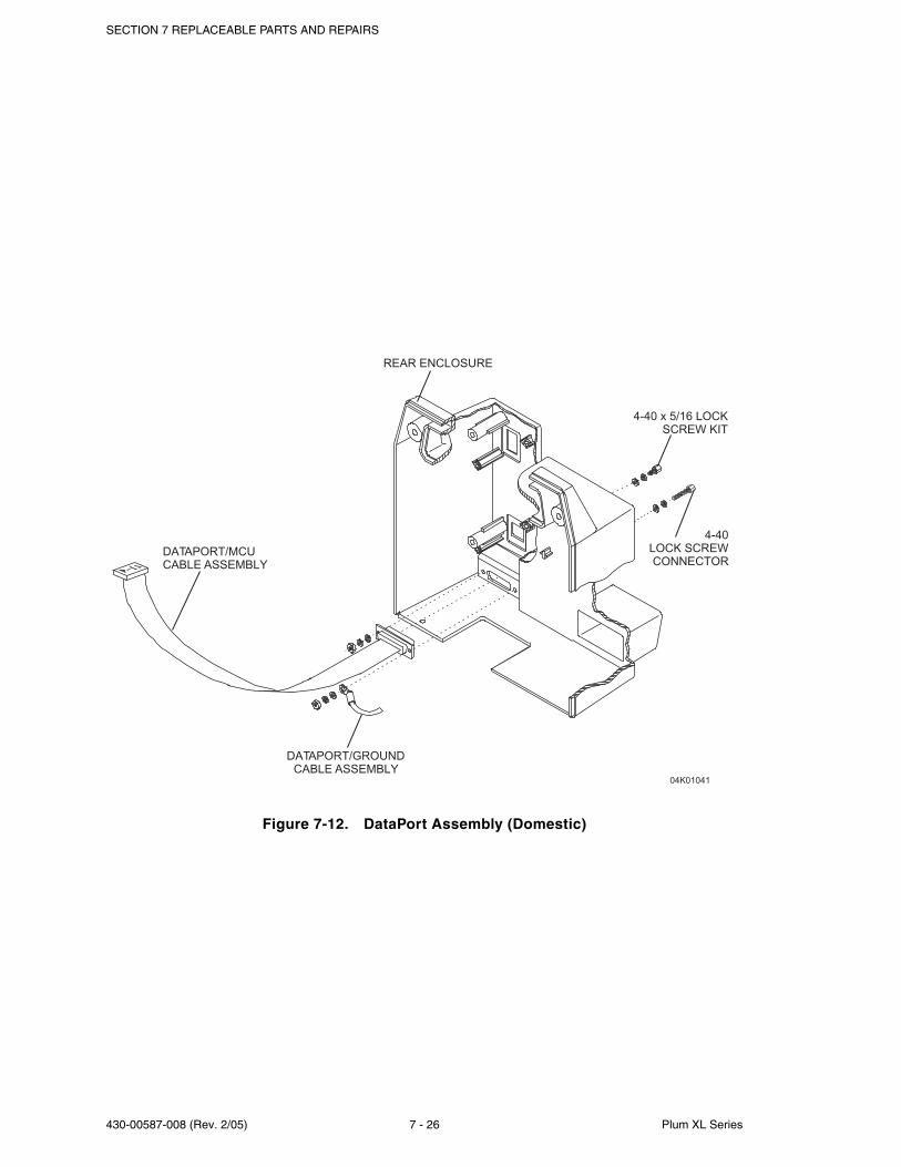
SECTION 7 REPLACEABLE PARTS AND REPAIRS
430-00587-008 (Rev. 2/05) 7 - 26 Plum XL Series
Figure 7-12. DataPort Assembly (Domestic)
4-40 x 5/16 LOCK
SCREW KIT
DATAPORT/GROUND
CABLE ASSEMBLY04K01041
4-40
LOCK SCREW
CONNECTOR
REAR ENCLOSURE
DATAPORT/MCU
CABLE ASSEMBLY
7.2 REPLACEMENT PROCEDURES
Technical Service Manual 7 - 27 430-00587-008 (Rev. 2/05)
7.2.8.9LIFECARE DATAPORT/MCU CABLE ASSEMBLY REPLACEMENT (XLM WITH DATAPORT)
Recommended tools for this procedure are a medium size flat blade screwdriver,1/4 inch nutdriver, 3/16 inch nutdriver, and 5/16 inch nutdriver.
The replacement parts for this procedure are:
Kit, Screw, Lock, 4-40 Assembly, Cable, DataPort/MCUGasket, DataPortBracket, DataPortCap, DataPortWasher, Shoulder, #4Screw, 4-40 x 1/4, Hex Head
CAUTION: Use proper ESD grounding techniques when handling components.Wear an antistatic wrist strap and use an ESD-protected workstation. Store the PWAin an antistatic bag before placing it on any surface.
Note: Do not connect DataPort when infusing.
To replace the DataPort/MCU cable assembly, refer to Figure 7-13, DataPort Assembly(International), and proceed as follows:
1. Separate the front enclosure assembly and rear enclosure assembly as describedin Section 7.2.5.
2. Remove the power supply PWA as described in Section 7.2.8.2.
3. Using the 1/4 nutdriver, remove the two hex head screws and two shoulder washerssecuring the DataPort cap. Remove the DataPort cap. Inspect all items for damageand replace if necessary.
4. Using the 3/16 nutdriver, remove the two 4-40 connector screws and washers onthe outside of the rear enclosure. Use the 1/4 nutdriver to keep the two 4-40 selflocking nuts on the inside of the rear enclosure from turning.
5. Disconnect the DataPort/ground cable.
6. Remove the DataPort bracket, inspect the bracket for damage and replace it ifnecessary.
7. Remove the DataPort gasket, inspect the gasket for damage and replace it ifnecessary.
8. Remove the DataPort/MCU cable assembly by pulling it through the rear enclosure.Inspect for damage and replace it if necessary.
9. Re-install the power supply PWA in the exact reverse order of removal.
10. Join the front enclosure assembly and rear enclosure assembly in the exact reverseorder of separation.
Note: (XLM with DataPort) When joining the front and rear enclosures, do notpinch the DataPort/MCU cable between the two enclosures.
11. Connect the infusion system to AC (mains) power.
To verify successful DataPort/MCU cable assembly replacement, perform the PVT inSection 5.2 and the DataPort connection and ground continuity test in Section 5.5.
EN-2
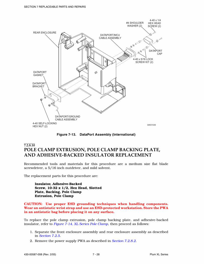
SECTION 7 REPLACEABLE PARTS AND REPAIRS
430-00587-008 (Rev. 2/05) 7 - 28 Plum XL Series
Figure 7-13. DataPort Assembly (International)
7.2.8.10POLE CLAMP EXTRUSION, POLE CLAMP BACKING PLATE, AND ADHESIVE-BACKED INSULATOR REPLACEMENT
Recommended tools and materials for this procedure are a medium size flat bladescrewdriver, a 5/16 inch nutdriver, and mild solvent.
The replacement parts for this procedure are:
Insulator, Adhesive-BackedScrew, 10-32 x 1/2, Hex Head, SlottedPlate, Backing, Pole ClampExtrusion, Pole Clamp
CAUTION: Use proper ESD grounding techniques when handling components.Wear an antistatic wrist strap and use an ESD-protected workstation. Store the PWAin an antistatic bag before placing it on any surface.
To replace the pole clamp extrusion, pole clamp backing plate, and adhesive-backedinsulator, refer to Figure 7-14, XL Series Pole Clamp, then proceed as follows:
1. Separate the front enclosure assembly and rear enclosure assembly as describedin Section 7.2.5.
2. Remove the power supply PWA as described in Section 7.2.8.2.
DATAPORT
GASKET
REAR ENCLOSURE
DATAPORT
BRACKET
4-40 SELF-LOCKING
HEX NUT (2)04K01039
DATAPORT/MCU
CABLE ASSEMBLY
4-40 x 5/16 LOCK
SCREW KIT (2)
DATAPORT/GROUND
CABLE ASSEMBLY
#4 SHOULDER
WASHER (2)
DATAPORT
CAP
4-40 x 1/4
HEX HEAD
SCREW (2)
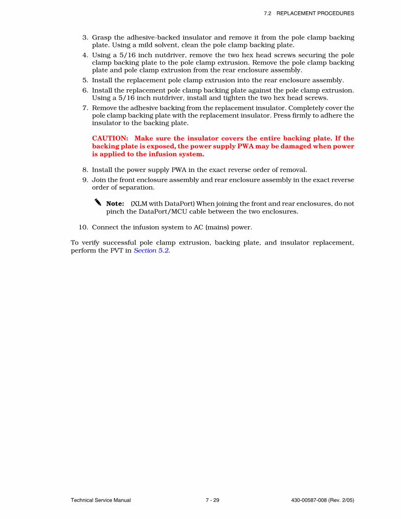
7.2 REPLACEMENT PROCEDURES
Technical Service Manual 7 - 29 430-00587-008 (Rev. 2/05)
3. Grasp the adhesive-backed insulator and remove it from the pole clamp backingplate. Using a mild solvent, clean the pole clamp backing plate.
4. Using a 5/16 inch nutdriver, remove the two hex head screws securing the poleclamp backing plate to the pole clamp extrusion. Remove the pole clamp backingplate and pole clamp extrusion from the rear enclosure assembly.
5. Install the replacement pole clamp extrusion into the rear enclosure assembly.
6. Install the replacement pole clamp backing plate against the pole clamp extrusion.Using a 5/16 inch nutdriver, install and tighten the two hex head screws.
7. Remove the adhesive backing from the replacement insulator. Completely cover thepole clamp backing plate with the replacement insulator. Press firmly to adhere theinsulator to the backing plate.
CAUTION: Make sure the insulator covers the entire backing plate. If thebacking plate is exposed, the power supply PWA may be damaged when poweris applied to the infusion system.
8. Install the power supply PWA in the exact reverse order of removal.
9. Join the front enclosure assembly and rear enclosure assembly in the exact reverseorder of separation.
Note: (XLM with DataPort) When joining the front and rear enclosures, do notpinch the DataPort/MCU cable between the two enclosures.
10. Connect the infusion system to AC (mains) power.
To verify successful pole clamp extrusion, backing plate, and insulator replacement,perform the PVT in Section 5.2.
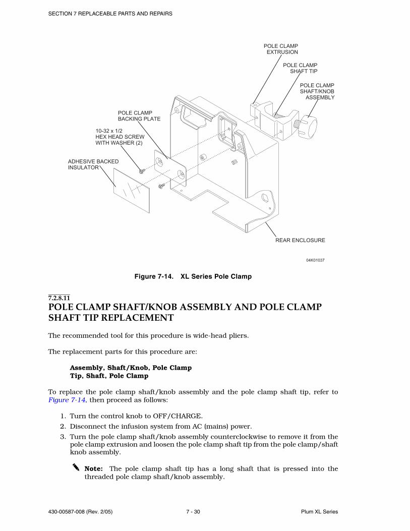
SECTION 7 REPLACEABLE PARTS AND REPAIRS
430-00587-008 (Rev. 2/05) 7 - 30 Plum XL Series
Figure 7-14. XL Series Pole Clamp
7.2.8.11POLE CLAMP SHAFT/KNOB ASSEMBLY AND POLE CLAMP SHAFT TIP REPLACEMENT
The recommended tool for this procedure is wide-head pliers.
The replacement parts for this procedure are:
Assembly, Shaft/Knob, Pole ClampTip, Shaft, Pole Clamp
To replace the pole clamp shaft/knob assembly and the pole clamp shaft tip, refer toFigure 7-14, then proceed as follows:
1. Turn the control knob to OFF/CHARGE.
2. Disconnect the infusion system from AC (mains) power.
3. Turn the pole clamp shaft/knob assembly counterclockwise to remove it from thepole clamp extrusion and loosen the pole clamp shaft tip from the pole clamp/shaftknob assembly.
Note: The pole clamp shaft tip has a long shaft that is pressed into thethreaded pole clamp shaft/knob assembly.
04K01037
POLE CLAMP
BACKING PLATE
ADHESIVE BACKED
INSULATOR
10-32 x 1/2
HEX HEAD SCREW
WITH WASHER (2)
POLE CLAMP
EXTRUSION
POLE CLAMP
SHAFT/KNOB
ASSEMBLY
POLE CLAMP
SHAFT TIP
REAR ENCLOSURE

7.2 REPLACEMENT PROCEDURES
Technical Service Manual 7 - 31 430-00587-008 (Rev. 2/05)
4. Turn the pole clamp shaft/knob assembly back into the pole clamp extrusion. Usingwide-head pliers, grasp the pole clamp shaft tip and remove. Replace the shaft tipif necessary.
5. Install the replacement pole clamp shaft/knob assembly into the pole clampextrusion by turning the shaft/knob assembly clockwise into the extrusion untilthe threaded portion is visible.
6. Press the pole clamp shaft tip into the screw hole recess on the pole clamp shaft/knob assembly and turn the shaft/knob assembly clockwise until the shaft tip issecure against the extrusion.
7. Connect the infusion system to AC (mains) power.
Replacement of the pole clamp shaft/knob assembly and the pole clamp shaft tip is aroutine maintenance procedure and no verification procedure is normally required.However, if the infusion system may have been damaged during the pole clamp knob andtip insert replacement, perform the PVT in Section 5.2.
7.2.8.12BUZZER PWA AND MCU/BUZZER CABLE REPLACEMENT
Recommended tools for this procedure are a medium size flat blade screwdriver and a 1/4 inch nutdriver.
The replacement parts for this procedure are:
PWA, BuzzerAssembly, Cable, MCU/BuzzerGasket, LockoutGasket, AudibleScrew, 6-32 x 3/8, Hex Head, Slotted
CAUTION: Use proper ESD grounding techniques when handling components.Wear an antistatic wrist strap and use an ESD-protected workstation. Store the PWAin an antistatic bag before placing it on any surface.
To replace the buzzer PWA, refer to Figure 7-15, Buzzer PWA, then proceed as follows:
1. Remove the power supply PWA as described in Section 7.2.8.2.
2. Remove the EMI shield.
3. Using a flat blade screwdriver, remove the four slotted hex head screws securingthe buzzer PWA to the rear enclosure assembly.
4. Inspect the MCU/Buzzer cable for damage and replace if necessary.
5. Remove the buzzer PWA from the rear enclosure assembly.
6. Inspect the audible gasket and the lockout gasket and replace if necessary (seeFigure 7-15).
7. Install the replacement buzzer PWA.
8. Reassemble the device in the exact reverse order of disassembly.
To verify successful buzzer PWA replacement, perform the PVT in Section 5.2.
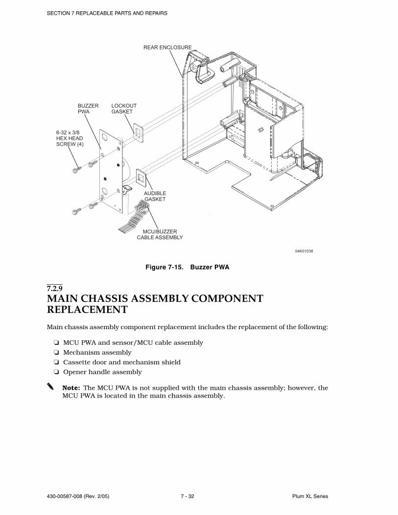
SECTION 7 REPLACEABLE PARTS AND REPAIRS
430-00587-008 (Rev. 2/05) 7 - 32 Plum XL Series
Figure 7-15. Buzzer PWA
7.2.9MAIN CHASSIS ASSEMBLY COMPONENT REPLACEMENT
Main chassis assembly component replacement includes the replacement of the following:
MCU PWA and sensor/MCU cable assembly
Mechanism assembly
Cassette door and mechanism shield
Opener handle assembly
Note: The MCU PWA is not supplied with the main chassis assembly; however, theMCU PWA is located in the main chassis assembly.
04K01038
6-32 x 3/8
HEX HEAD
SCREW (4)
BUZZER
PWA
REAR ENCLOSURE
MCU/BUZZER
CABLE ASSEMBLY
AUDIBLE
GASKET
LOCKOUT
GASKET
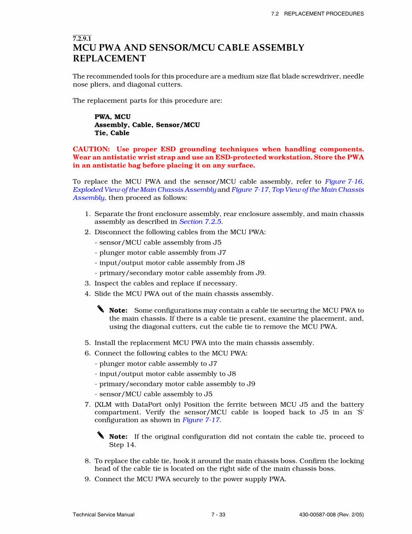
7.2 REPLACEMENT PROCEDURES
Technical Service Manual 7 - 33 430-00587-008 (Rev. 2/05)
7.2.9.1MCU PWA AND SENSOR/MCU CABLE ASSEMBLY REPLACEMENT
The recommended tools for this procedure are a medium size flat blade screwdriver, needlenose pliers, and diagonal cutters.
The replacement parts for this procedure are:
PWA, MCUAssembly, Cable, Sensor/MCUTie, Cable
CAUTION: Use proper ESD grounding techniques when handling components.Wear an antistatic wrist strap and use an ESD-protected workstation. Store the PWAin an antistatic bag before placing it on any surface.
To replace the MCU PWA and the sensor/MCU cable assembly, refer to Figure 7-16,Exploded View of the Main Chassis Assembly and Figure 7-17, Top View of the Main ChassisAssembly, then proceed as follows:
1. Separate the front enclosure assembly, rear enclosure assembly, and main chassisassembly as described in Section 7.2.5.
2. Disconnect the following cables from the MCU PWA:
- sensor/MCU cable assembly from J5
- plunger motor cable assembly from J7
- input/output motor cable assembly from J8
- primary/secondary motor cable assembly from J9.
3. Inspect the cables and replace if necessary.
4. Slide the MCU PWA out of the main chassis assembly.
Note: Some configurations may contain a cable tie securing the MCU PWA tothe main chassis. If there is a cable tie present, examine the placement, and,using the diagonal cutters, cut the cable tie to remove the MCU PWA.
5. Install the replacement MCU PWA into the main chassis assembly.
6. Connect the following cables to the MCU PWA:
- plunger motor cable assembly to J7
- input/output motor cable assembly to J8
- primary/secondary motor cable assembly to J9
- sensor/MCU cable assembly to J5
7. (XLM with DataPort only) Position the ferrite between MCU J5 and the batterycompartment. Verify the sensor/MCU cable is looped back to J5 in an 'S'configuration as shown in Figure 7-17.
Note: If the original configuration did not contain the cable tie, proceed toStep 14.
8. To replace the cable tie, hook it around the main chassis boss. Confirm the lockinghead of the cable tie is located on the right side of the main chassis boss.
9. Connect the MCU PWA securely to the power supply PWA.
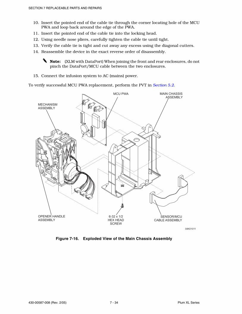
SECTION 7 REPLACEABLE PARTS AND REPAIRS
430-00587-008 (Rev. 2/05) 7 - 34 Plum XL Series
10. Insert the pointed end of the cable tie through the corner locating hole of the MCUPWA and loop back around the edge of the PWA.
11. Insert the pointed end of the cable tie into the locking head.
12. Using needle nose pliers, carefully tighten the cable tie until tight.
13. Verify the cable tie is tight and cut away any excess using the diagonal cutters.
14. Reassemble the device in the exact reverse order of disassembly.
Note: (XLM with DataPort) When joining the front and rear enclosures, do notpinch the DataPort/MCU cable between the two enclosures.
15. Connect the infusion system to AC (mains) power.
To verify successful MCU PWA replacement, perform the PVT in Section 5.2.
Figure 7-16. Exploded View of the Main Chassis Assembly
04K01011
OPENER HANDLE
ASSEMBLY
MECHANISM
ASSEMBLY
MCU PWA
6-32 x 1/2
HEX HEAD
SCREW
MAIN CHASSIS
ASSEMBLY
SENSOR/MCU
CABLE ASSEMBLY
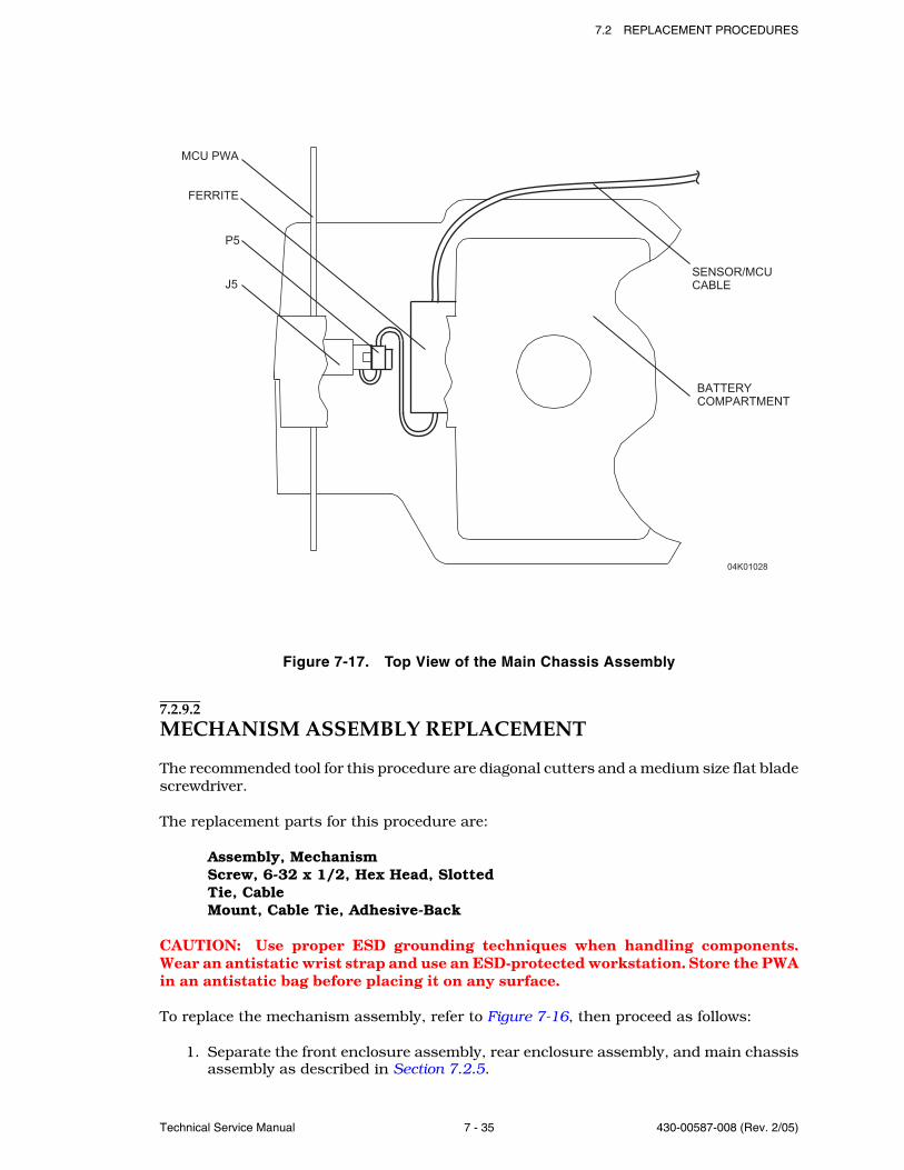
7.2 REPLACEMENT PROCEDURES
Technical Service Manual 7 - 35 430-00587-008 (Rev. 2/05)
Figure 7-17. Top View of the Main Chassis Assembly
7.2.9.2MECHANISM ASSEMBLY REPLACEMENT
The recommended tool for this procedure are diagonal cutters and a medium size flat bladescrewdriver.
The replacement parts for this procedure are:
Assembly, MechanismScrew, 6-32 x 1/2, Hex Head, SlottedTie, CableMount, Cable Tie, Adhesive-Back
CAUTION: Use proper ESD grounding techniques when handling components.Wear an antistatic wrist strap and use an ESD-protected workstation. Store the PWAin an antistatic bag before placing it on any surface.
To replace the mechanism assembly, refer to Figure 7-16, then proceed as follows:
1. Separate the front enclosure assembly, rear enclosure assembly, and main chassisassembly as described in Section 7.2.5.
MCU PWA
FERRITE
P5
J5
SENSOR/MCU
CABLE
BATTERY
COMPARTMENT
04K01028
SECTION 7 REPLACEABLE PARTS AND REPAIRS
430-00587-008 (Rev. 2/05) 7 - 36 Plum XL Series
2. Remove the MCU PWA as described in Section 7.2.9.1. Disconnect the sensor/MCUcable assembly from the mechanism assembly at J6.
3. Using a medium size flat blade screwdriver, remove the hex head screw securingthe mechanism assembly to the main chassis assembly.
Note: (International devices only) Use the diagonal cutters to cut the cable tieholding the mechanism assembly cables to the main chassis assembly. Inspectthe cable tie mount and replace if damaged.
4. Remove the mechanism assembly from the main chassis assembly.
5. Using a medium size flat blade screwdriver, replace and tighten the hex head screwto secure the replacement mechanism assembly to the main chassis assembly.
6. Connect the sensor/MCU cable assembly to the replacement mechanism assemblyat J6. Replace the MCU PWA in the exact reverse order of removal.
7. Join the front enclosure assembly, rear enclosure assembly, and main chassisassembly in the exact reverse order of separation.
Note: (XLM with DataPort) When joining the front and rear enclosures, do notpinch the DataPort/MCU cable between the two enclosures.
8. Connect the infusion system to AC (mains) power.
9. (XLM with DataPort only) Perform the following steps to verify proper operation ofthe DataPort:
- Enter the service mode as described in Section 6.2.3.
- Verify the value of the communication selection as described in Section 6.2.3.4.1. Update the value if necessary.
- Verify the value of the channel label as described in Section 6.2.3.4.3. Update the value if necessary.
To verify successful mechanism assembly replacement, perform the PVT in Section 5.2.
7.2.9.3CASSETTE DOOR AND MECHANISM SHIELD REPLACEMENT
Recommended tools for this procedure are a medium size flat blade screwdriver and longneedle nose pliers.
The replacement parts for this procedure are:
Shield, MechanismRetainer, Door PivotSpring, Door Clip, Left-SideAssembly, Door
CAUTION: Use proper ESD grounding techniques when handling components.Wear an antistatic wrist strap and use an ESD-protected workstation. Store the PWAin an antistatic bag before placing it on any surface.
To replace the cassette door and mechanism shield, refer to Figure 7-18, Mechanism ShieldReplacement; Figure 7-19 through Figure 7-21, Cassette Door Replacement (3 of 3); andFigure 7-22, Cassette Door Replacement, Bottom View, then proceed as follows:
1. Separate the front enclosure assembly, rear enclosure assembly, and main chassisassembly as described in Section 7.2.5.
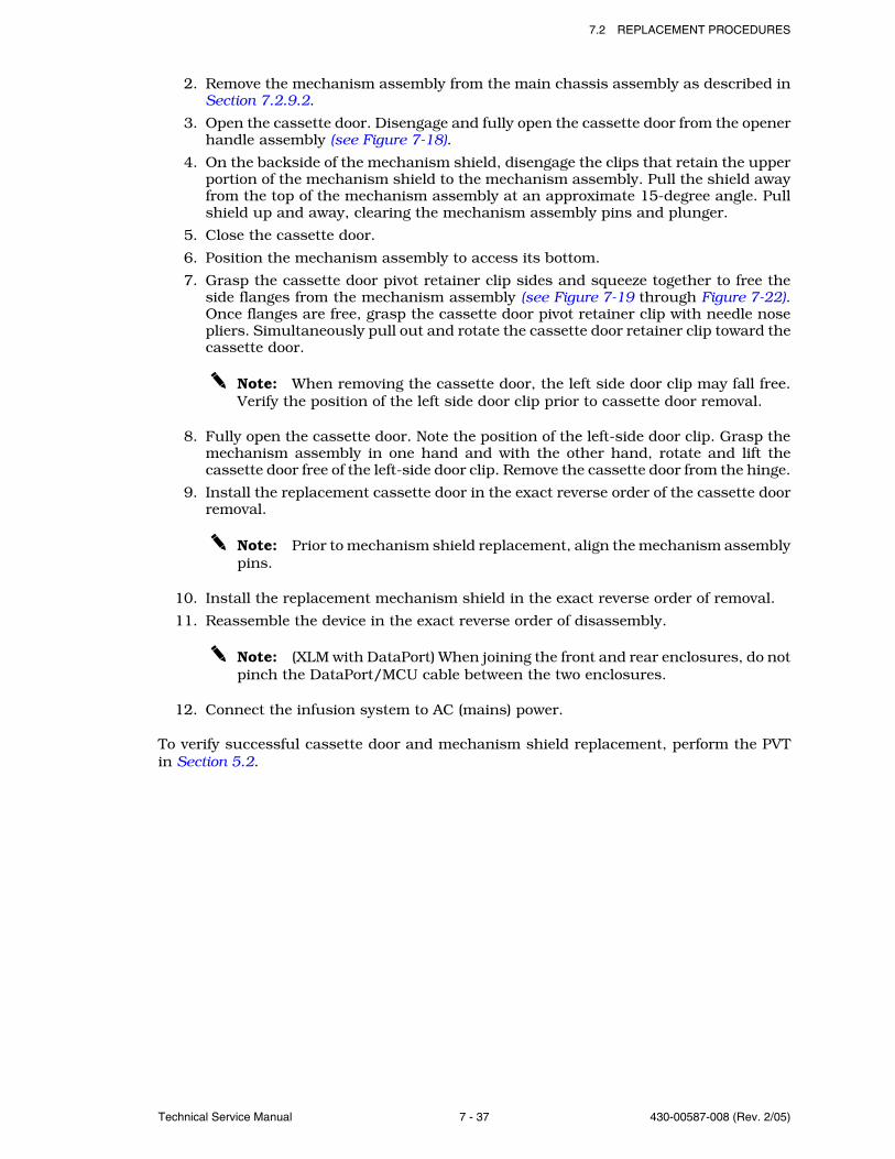
7.2 REPLACEMENT PROCEDURES
Technical Service Manual 7 - 37 430-00587-008 (Rev. 2/05)
2. Remove the mechanism assembly from the main chassis assembly as described inSection 7.2.9.2.
3. Open the cassette door. Disengage and fully open the cassette door from the openerhandle assembly (see Figure 7-18).
4. On the backside of the mechanism shield, disengage the clips that retain the upperportion of the mechanism shield to the mechanism assembly. Pull the shield awayfrom the top of the mechanism assembly at an approximate 15-degree angle. Pullshield up and away, clearing the mechanism assembly pins and plunger.
5. Close the cassette door.
6. Position the mechanism assembly to access its bottom.
7. Grasp the cassette door pivot retainer clip sides and squeeze together to free theside flanges from the mechanism assembly (see Figure 7-19 through Figure 7-22).Once flanges are free, grasp the cassette door pivot retainer clip with needle nosepliers. Simultaneously pull out and rotate the cassette door retainer clip toward thecassette door.
Note: When removing the cassette door, the left side door clip may fall free.Verify the position of the left side door clip prior to cassette door removal.
8. Fully open the cassette door. Note the position of the left-side door clip. Grasp themechanism assembly in one hand and with the other hand, rotate and lift thecassette door free of the left-side door clip. Remove the cassette door from the hinge.
9. Install the replacement cassette door in the exact reverse order of the cassette doorremoval.
Note: Prior to mechanism shield replacement, align the mechanism assemblypins.
10. Install the replacement mechanism shield in the exact reverse order of removal.
11. Reassemble the device in the exact reverse order of disassembly.
Note: (XLM with DataPort) When joining the front and rear enclosures, do notpinch the DataPort/MCU cable between the two enclosures.
12. Connect the infusion system to AC (mains) power.
To verify successful cassette door and mechanism shield replacement, perform the PVTin Section 5.2.
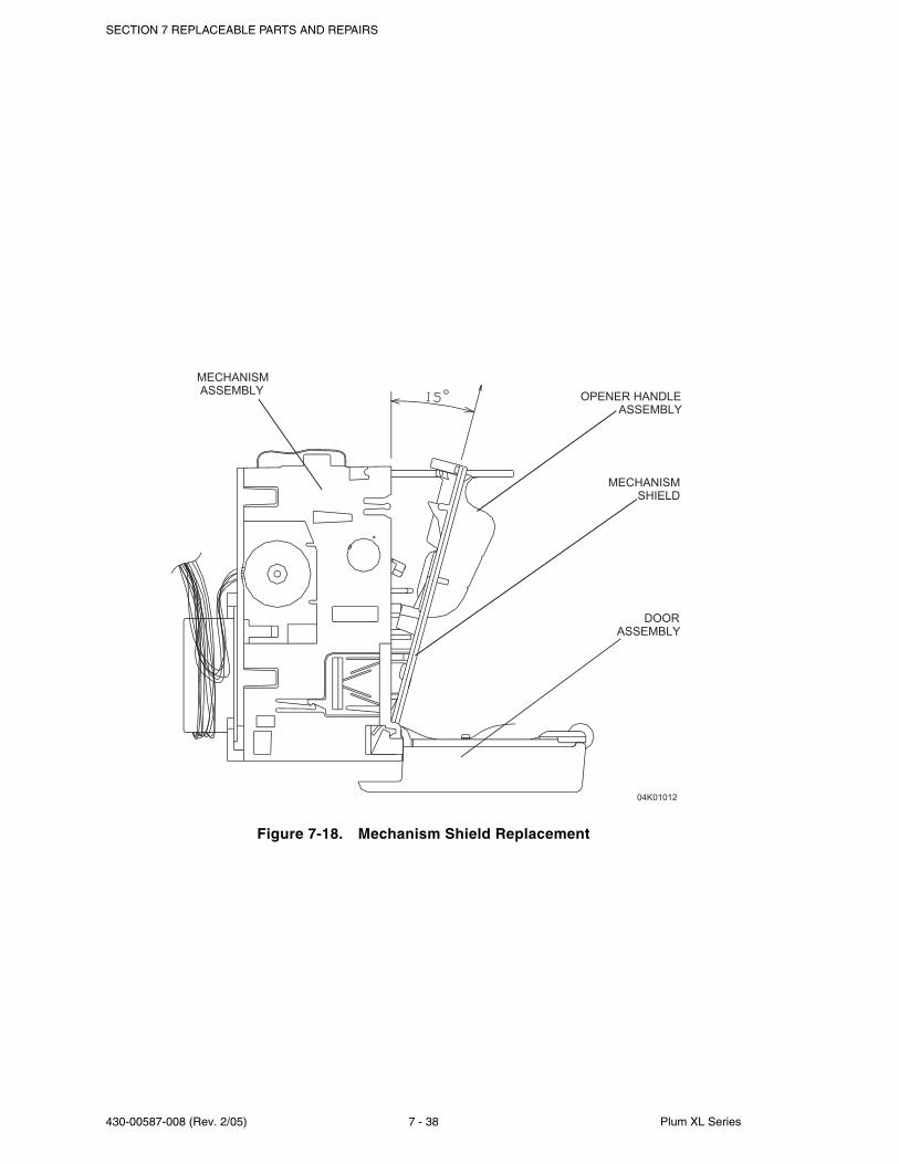
SECTION 7 REPLACEABLE PARTS AND REPAIRS
430-00587-008 (Rev. 2/05) 7 - 38 Plum XL Series
Figure 7-18. Mechanism Shield Replacement
04K01012
DOOR
ASSEMBLY
OPENER HANDLE
ASSEMBLY
MECHANISM
SHIELD
MECHANISM
ASSEMBLY
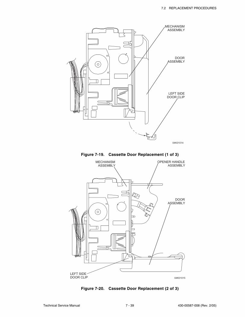
7.2 REPLACEMENT PROCEDURES
Technical Service Manual 7 - 39 430-00587-008 (Rev. 2/05)
Figure 7-19. Cassette Door Replacement (1 of 3)
Figure 7-20. Cassette Door Replacement (2 of 3)
04K01014
MECHANISM
ASSEMBLY
DOOR
ASSEMBLY
LEFT SIDE
DOOR CLIP
04K01015
OPENER HANDLE
ASSEMBLY
DOOR
ASSEMBLY
LEFT SIDE
DOOR CLIP
MECHANISM
ASSEMBLY
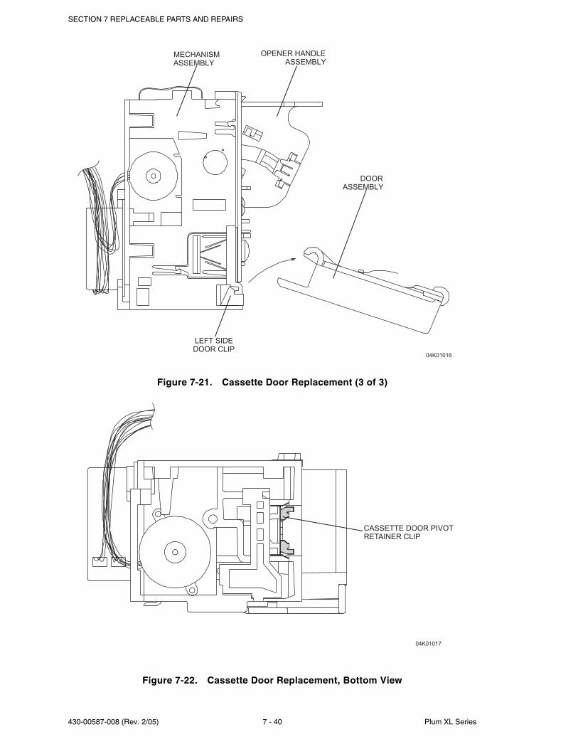
SECTION 7 REPLACEABLE PARTS AND REPAIRS
430-00587-008 (Rev. 2/05) 7 - 40 Plum XL Series
Figure 7-21. Cassette Door Replacement (3 of 3)
Figure 7-22. Cassette Door Replacement, Bottom View
04K01017
CASSETTE DOOR PIVOT
RETAINER CLIP
04K01016
MECHANISM
ASSEMBLY
OPENER HANDLE
ASSEMBLY
DOOR
ASSEMBLY
LEFT SIDE
DOOR CLIP
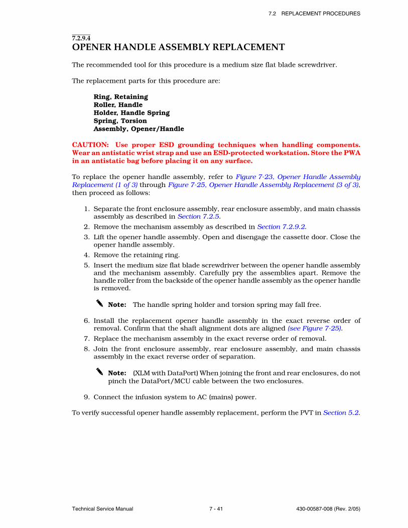
7.2 REPLACEMENT PROCEDURES
Technical Service Manual 7 - 41 430-00587-008 (Rev. 2/05)
7.2.9.4OPENER HANDLE ASSEMBLY REPLACEMENT
The recommended tool for this procedure is a medium size flat blade screwdriver.
The replacement parts for this procedure are:
Ring, RetainingRoller, HandleHolder, Handle SpringSpring, TorsionAssembly, Opener/Handle
CAUTION: Use proper ESD grounding techniques when handling components.Wear an antistatic wrist strap and use an ESD-protected workstation. Store the PWAin an antistatic bag before placing it on any surface.
To replace the opener handle assembly, refer to Figure 7-23, Opener Handle AssemblyReplacement (1 of 3) through Figure 7-25, Opener Handle Assembly Replacement (3 of 3),then proceed as follows:
1. Separate the front enclosure assembly, rear enclosure assembly, and main chassisassembly as described in Section 7.2.5.
2. Remove the mechanism assembly as described in Section 7.2.9.2.
3. Lift the opener handle assembly. Open and disengage the cassette door. Close theopener handle assembly.
4. Remove the retaining ring.
5. Insert the medium size flat blade screwdriver between the opener handle assemblyand the mechanism assembly. Carefully pry the assemblies apart. Remove thehandle roller from the backside of the opener handle assembly as the opener handleis removed.
Note: The handle spring holder and torsion spring may fall free.
6. Install the replacement opener handle assembly in the exact reverse order ofremoval. Confirm that the shaft alignment dots are aligned (see Figure 7-25).
7. Replace the mechanism assembly in the exact reverse order of removal.
8. Join the front enclosure assembly, rear enclosure assembly, and main chassisassembly in the exact reverse order of separation.
Note: (XLM with DataPort) When joining the front and rear enclosures, do notpinch the DataPort/MCU cable between the two enclosures.
9. Connect the infusion system to AC (mains) power.
To verify successful opener handle assembly replacement, perform the PVT in Section 5.2.
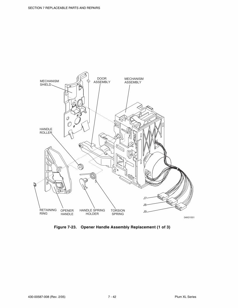
SECTION 7 REPLACEABLE PARTS AND REPAIRS
430-00587-008 (Rev. 2/05) 7 - 42 Plum XL Series
Figure 7-23. Opener Handle Assembly Replacement (1 of 3)
04K01001
RETAINING
RING
HANDLE SPRING
HOLDER
TORSION
SPRING
J7
J8
J9OPENER
HANDLE
HANDLE
ROLLER
MECHANISM
ASSEMBLYMECHANISM
SHIELD
DOOR
ASSEMBLY
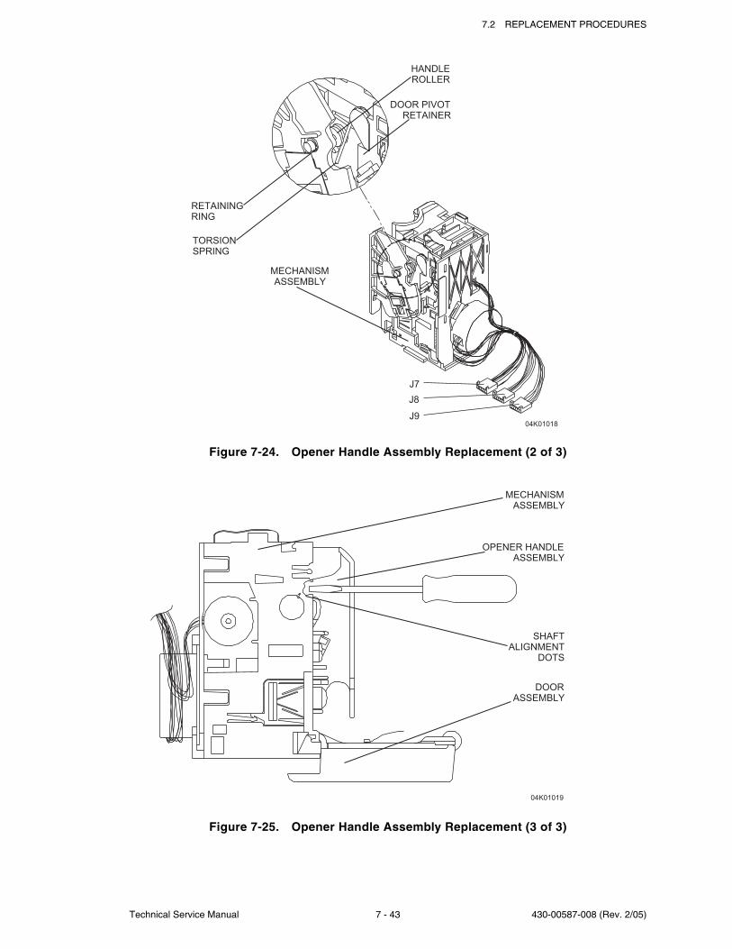
7.2 REPLACEMENT PROCEDURES
Technical Service Manual 7 - 43 430-00587-008 (Rev. 2/05)
Figure 7-24. Opener Handle Assembly Replacement (2 of 3)
Figure 7-25. Opener Handle Assembly Replacement (3 of 3)
04K01018
HANDLE
ROLLER
DOOR PIVOT
RETAINER
TORSION
SPRING
RETAINING
RING
MECHANISM
ASSEMBLY
J7
J8
J9
04K01019
DOOR
ASSEMBLY
SHAFT
ALIGNMENT
DOTS
OPENER HANDLE
ASSEMBLY
MECHANISM
ASSEMBLY

SECTION 7 REPLACEABLE PARTS AND REPAIRS
430-00587-008 (Rev. 2/05) 7 - 44 Plum XL Series
This page intentionally left blank.
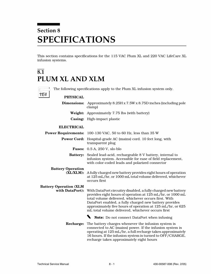
Technical Service Manual 8 - 1 430-00587-008 (Rev. 2/05)
Section 8
SPECIFICATIONS
This section contains specifications for the 115 VAC Plum XL and 220 VAC LifeCare XLinfusion systems.
8.1PLUM XL AND XLM
The following specifications apply to the Plum XL infusion system only.
PHYSICAL
Dimensions: Approximately 8.25H x 7.5W x 8.75D inches (including pole clamp)
Weight: Approximately 7.75 lbs (with battery)
Casing: High-impact plastic
ELECTRICAL
Power Requirements: 100-130 VAC, 50 to 60 Hz, less than 35 W
Power Cord: Hospital-grade AC (mains) cord. 10 feet long, with transparent plug
Fuses: 0.5 A, 250 V, slo-blo
Battery: Sealed lead-acid, rechargeable 8 V battery, internal to infusion system. Accessible for ease of field replacement, with color-coded leads and polarized connector
Battery Operation(XL/XLM): A fully charged new battery provides eight hours of operation
at 125 mL/hr, or 1000 mL total volume delivered, whichever occurs first
Battery Operation (XLMwith DataPort): With DataPort circuitry disabled, a fully charged new battery
provides eight hours of operation at 125 mL/hr, or 1000 mL total volume delivered, whichever occurs first. With DataPort enabled, a fully charged new battery provides approximately five hours of operation at 125 mL/hr, or 625 mL total volume delivered, whichever occurs first
Note: Do not connect DataPort when infusing
Recharge: The battery charges whenever the infusion system is connected to AC (mains) power. If the infusion system is operating at 125 mL/hr, a full recharge takes approximately 16 hours. If the infusion system is turned to OFF/CHARGE, recharge takes approximately eight hours
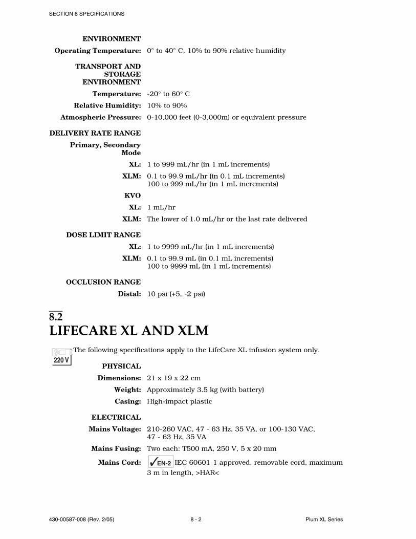
SECTION 8 SPECIFICATIONS
430-00587-008 (Rev. 2/05) 8 - 2 Plum XL Series
ENVIRONMENT
Operating Temperature: 0° to 40° C, 10% to 90% relative humidity
TRANSPORT ANDSTORAGE
ENVIRONMENT
Temperature: -20° to 60° C
Relative Humidity: 10% to 90%
Atmospheric Pressure: 0-10,000 feet (0-3,000m) or equivalent pressure
DELIVERY RATE RANGE
Primary, SecondaryMode
XL: 1 to 999 mL/hr (in 1 mL increments)
XLM: 0.1 to 99.9 mL/hr (in 0.1 mL increments)100 to 999 mL/hr (in 1 mL increments)
KVO
XL: 1 mL/hr
XLM: The lower of 1.0 mL/hr or the last rate delivered
DOSE LIMIT RANGE
XL: 1 to 9999 mL/hr (in 1 mL increments)
XLM: 0.1 to 99.9 mL (in 0.1 mL increments)100 to 9999 mL (in 1 mL increments)
OCCLUSION RANGE
Distal: 10 psi (+5, -2 psi)
8.2LIFECARE XL AND XLM
The following specifications apply to the LifeCare XL infusion system only.
PHYSICAL
Dimensions: 21 x 19 x 22 cm
Weight: Approximately 3.5 kg (with battery)
Casing: High-impact plastic
ELECTRICAL
Mains Voltage: 210-260 VAC, 47 - 63 Hz, 35 VA, or 100-130 VAC, 47 - 63 Hz, 35 VA
Mains Fusing: Two each: T500 mA, 250 V, 5 x 20 mm
Mains Cord: IEC 60601-1 approved, removable cord, maximum
3 m in length, >HAR<EN-2

8.2 LIFECARE XL AND XLM
Technical Service Manual 8 - 3 430-00587-008 (Rev. 2/05)
Battery: One 8 V, sealed, rechargeable battery, internal to the infusion system. Accessible for ease of field replacement, with color-coded leads and polarized connector
Battery Operating Time(XL/XLM): With a new, fully charged battery, the infusion system
provides approximately 1000 mL delivery volume or eight hours of operation, whichever occurs first. The infusion system displays a low battery alarm approximately 30 minutes prior to infusion system shutdown when pumping at 125 mL/hr. If a low battery alarm occurs, immediately connect the infusion system to mains power
Note: Gradual degradation over extended periods ofuse decreases the operational capacity of the battery.Typical battery life is three years. A yearly check isrecommended to verify performance. When capacitydrops to an unacceptable level, replace the battery.Battery replacement must be performed by qualifiedtechnical personnel
Battery Operating Time(XLM with DataPort): With DataPort circuitry disabled, a fully charged new battery
provides eight hours of operation, or 1000 mL total volume delivered, whichever occurs first. With DataPort enabled, a fully charged new battery provides approximately five hours of operation, or 625 mL total volume delivered, whichever occurs first. The infusion system displays a low battery alarm approximately 30 minutes prior to infusion system shutdown when pumping at 125 mL/hr. If a low battery alarm occurs, immediately connect the infusion system to mains power
Note: Do not connect DataPort when infusing
Note: Gradual degradation over extended periods ofuse decreases the operational capacity of the battery.Typical battery life is three years. A yearly check isrecommended to verify performance. When capacitydrops to an unacceptable level, replace the battery.Battery replacement must be performed by qualifiedtechnical personnel
Battery Recharge: The battery recharges when the infusion system is connected to mains power. If the infusion system is operating at 125 mL/hr, a full recharge takes approximately 16 hours. Recharge takes approximately eight hours if the infusion system is turned to the OFF/CHARGE position
Battery ChargeRetention: A fully charged battery retains at least 20 percent of its
capacity after six months of storage at below 35° C (95° F) in an infusion system not connected to mains power
ENVIRONMENT
Operating Temperature: 0° to 40° C (50° to 104° F) 10 percent to 90 percent relative humidity
Shipping and Storage: -20° to 60° C (-4° to 140° F) 10 percent to 90 percent relative humidity
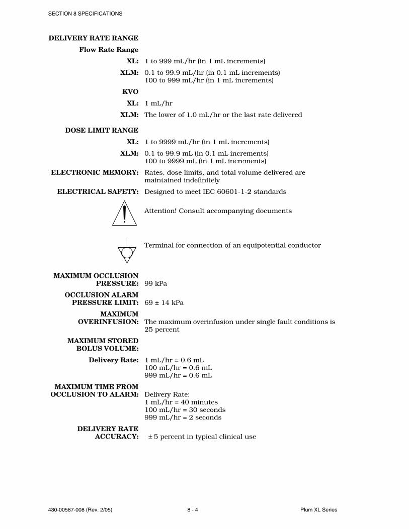
SECTION 8 SPECIFICATIONS
430-00587-008 (Rev. 2/05) 8 - 4 Plum XL Series
DELIVERY RATE RANGE
Flow Rate Range
XL: 1 to 999 mL/hr (in 1 mL increments)
XLM: 0.1 to 99.9 mL/hr (in 0.1 mL increments)100 to 999 mL/hr (in 1 mL increments)
KVO
XL: 1 mL/hr
XLM: The lower of 1.0 mL/hr or the last rate delivered
DOSE LIMIT RANGE
XL: 1 to 9999 mL/hr (in 1 mL increments)
XLM: 0.1 to 99.9 mL (in 0.1 mL increments)100 to 9999 mL (in 1 mL increments)
ELECTRONIC MEMORY: Rates, dose limits, and total volume delivered are maintained indefinitely
ELECTRICAL SAFETY: Designed to meet IEC 60601-1-2 standards
Attention! Consult accompanying documents
Terminal for connection of an equipotential conductor
MAXIMUM OCCLUSIONPRESSURE: 99 kPa
OCCLUSION ALARMPRESSURE LIMIT: 69 ± 14 kPa
MAXIMUMOVERINFUSION: The maximum overinfusion under single fault conditions is
25 percent
MAXIMUM STOREDBOLUS VOLUME:
Delivery Rate: 1 mL/hr = 0.6 mL100 mL/hr = 0.6 mL999 mL/hr = 0.6 mL
MAXIMUM TIME FROMOCCLUSION TO ALARM: Delivery Rate:
1 mL/hr = 40 minutes100 mL/hr = 30 seconds999 mL/hr = 2 seconds
DELIVERY RATEACCURACY: ± 5 percent in typical clinical use
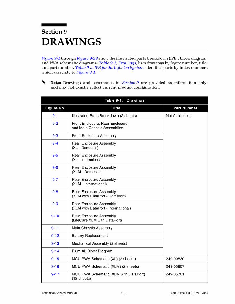
Technical Service Manual 9 - 1 430-00587-008 (Rev. 2/05)
Section 9
DRAWINGSFigure 9-1 through Figure 9-28 show the illustrated parts breakdown (IPB), block diagram,and PWA schematic diagrams. Table 9-1, Drawings, lists drawings by figure number, title,and part number. Table 9-2, IPB for the Infusion System, identifies parts by index numberswhich correlate to Figure 9-1.
Note: Drawings and schematics in Section 9 are provided as information only,and may not exactly reflect current product configuration.
Table 9-1. Drawings
Figure No. Title Part Number
9-1 Illustrated Parts Breakdown (2 sheets) Not Applicable
9-2 Front Enclosure, Rear Enclosure,and Main Chassis Assemblies
9-3 Front Enclosure Assembly
9-4 Rear Enclosure Assembly (XL - Domestic)
9-5 Rear Enclosure Assembly (XL - International)
9-6 Rear Enclosure Assembly (XLM - Domestic)
9-7 Rear Enclosure Assembly(XLM - International)
9-8 Rear Enclosure Assembly(XLM with DataPort - Domestic)
9-9 Rear Enclosure Assembly(XLM with DataPort - International)
9-10 Rear Enclosure Assembly (LifeCare XLM with DataPort)
9-11 Main Chassis Assembly
9-12 Battery Replacement
9-13 Mechanical Assembly (2 sheets)
9-14 Plum XL Block Diagram
9-15 MCU PWA Schematic (XL) (2 sheets) 249-00530
9-16 MCU PWA Schematic (XLM) (2 sheets) 249-05907
9-17 MCU PWA Schematic (XLM with DataPort)(18 sheets)
249-05701
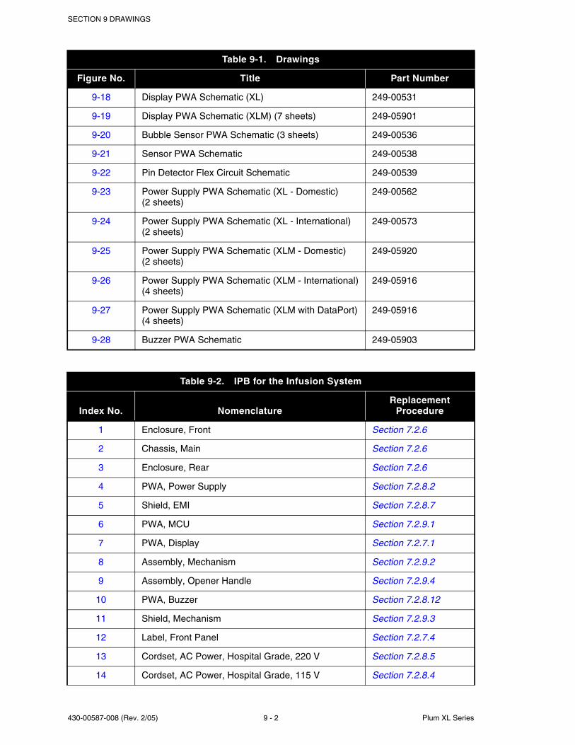
SECTION 9 DRAWINGS
430-00587-008 (Rev. 2/05) 9 - 2 Plum XL Series
9-18 Display PWA Schematic (XL) 249-00531
9-19 Display PWA Schematic (XLM) (7 sheets) 249-05901
9-20 Bubble Sensor PWA Schematic (3 sheets) 249-00536
9-21 Sensor PWA Schematic 249-00538
9-22 Pin Detector Flex Circuit Schematic 249-00539
9-23 Power Supply PWA Schematic (XL - Domestic)(2 sheets)
249-00562
9-24 Power Supply PWA Schematic (XL - International)(2 sheets)
249-00573
9-25 Power Supply PWA Schematic (XLM - Domestic)(2 sheets)
249-05920
9-26 Power Supply PWA Schematic (XLM - International)(4 sheets)
249-05916
9-27 Power Supply PWA Schematic (XLM with DataPort)(4 sheets)
249-05916
9-28 Buzzer PWA Schematic 249-05903
Table 9-2. IPB for the Infusion System
Index No. NomenclatureReplacement
Procedure
1 Enclosure, Front Section 7.2.6
2 Chassis, Main Section 7.2.6
3 Enclosure, Rear Section 7.2.6
4 PWA, Power Supply Section 7.2.8.2
5 Shield, EMI Section 7.2.8.7
6 PWA, MCU Section 7.2.9.1
7 PWA, Display Section 7.2.7.1
8 Assembly, Mechanism Section 7.2.9.2
9 Assembly, Opener Handle Section 7.2.9.4
10 PWA, Buzzer Section 7.2.8.12
11 Shield, Mechanism Section 7.2.9.3
12 Label, Front Panel Section 7.2.7.4
13 Cordset, AC Power, Hospital Grade, 220 V Section 7.2.8.5
14 Cordset, AC Power, Hospital Grade, 115 V Section 7.2.8.4
Table 9-1. Drawings
Figure No. Title Part Number
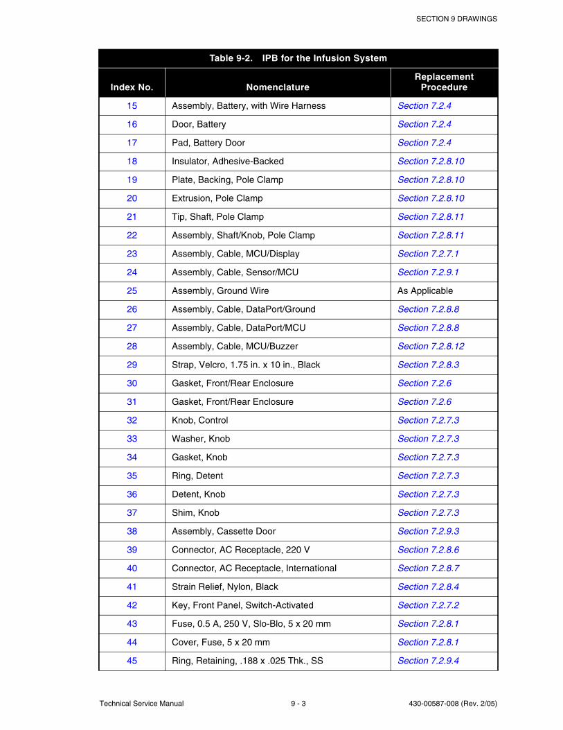
SECTION 9 DRAWINGS
Technical Service Manual 9 - 3 430-00587-008 (Rev. 2/05)
15 Assembly, Battery, with Wire Harness Section 7.2.4
16 Door, Battery Section 7.2.4
17 Pad, Battery Door Section 7.2.4
18 Insulator, Adhesive-Backed Section 7.2.8.10
19 Plate, Backing, Pole Clamp Section 7.2.8.10
20 Extrusion, Pole Clamp Section 7.2.8.10
21 Tip, Shaft, Pole Clamp Section 7.2.8.11
22 Assembly, Shaft/Knob, Pole Clamp Section 7.2.8.11
23 Assembly, Cable, MCU/Display Section 7.2.7.1
24 Assembly, Cable, Sensor/MCU Section 7.2.9.1
25 Assembly, Ground Wire As Applicable
26 Assembly, Cable, DataPort/Ground Section 7.2.8.8
27 Assembly, Cable, DataPort/MCU Section 7.2.8.8
28 Assembly, Cable, MCU/Buzzer Section 7.2.8.12
29 Strap, Velcro, 1.75 in. x 10 in., Black Section 7.2.8.3
30 Gasket, Front/Rear Enclosure Section 7.2.6
31 Gasket, Front/Rear Enclosure Section 7.2.6
32 Knob, Control Section 7.2.7.3
33 Washer, Knob Section 7.2.7.3
34 Gasket, Knob Section 7.2.7.3
35 Ring, Detent Section 7.2.7.3
36 Detent, Knob Section 7.2.7.3
37 Shim, Knob Section 7.2.7.3
38 Assembly, Cassette Door Section 7.2.9.3
39 Connector, AC Receptacle, 220 V Section 7.2.8.6
40 Connector, AC Receptacle, International Section 7.2.8.7
41 Strain Relief, Nylon, Black Section 7.2.8.4
42 Key, Front Panel, Switch-Activated Section 7.2.7.2
43 Fuse, 0.5 A, 250 V, Slo-Blo, 5 x 20 mm Section 7.2.8.1
44 Cover, Fuse, 5 x 20 mm Section 7.2.8.1
45 Ring, Retaining, .188 x .025 Thk., SS Section 7.2.9.4
Table 9-2. IPB for the Infusion System
Index No. NomenclatureReplacement
Procedure

SECTION 9 DRAWINGS
430-00587-008 (Rev. 2/05) 9 - 4 Plum XL Series
46 Roller, Handle Section 7.2.9.4
47 Holder, Handle Spring Section 7.2.9.4
48 Spring, Torsion Section 7.2.9.4
49 Retainer, Door Pivot Section 7.2.9.3
50 Retainer, Snap, Knob Section 7.2.7.3
51 Magnet Section 7.2.7.3
52 Spring, Door Clip, Left-Side Section 7.2.9.3
53 Foot, Rubber Section 7.2.3
54 Gasket, Lockout Section 7.2.8.12
55 Gasket, Audible Section 7.2.8.12
56 Housing, Seal, AC Receptacle Section 7.2.8.7
57 Gasket, AC Receptacle Section 7.2.8.7
58 Bracket, AC Receptacle Section 7.2.8.7
59 Gasket, DataPort Section 7.2.8.9
60 Bracket, DataPort Section 7.2.8.9
61 Post, Equipotential Section 7.2.8.6, Section 7.2.8.7
62 Bumper, XL MCU Section 7.2.7.1
63 Screw, 6-32 x 1/2, Hex Head, Slotted, with Washer As Applicable
64 Screw, 10-32 x 1/2, Hex Head, Slotted, with Washer As Applicable
65 Screw, 6-32 x 5/16, Hex Head, Slotted, with Washer As Applicable
66 Screw, 4-24 x 3/8, B/Point, Phillips As Applicable
67 Screw, 6-32 x 3/4, Hex Head, Slotted, with Washer As Applicable
68 Screw, 6-32 x 3/8, Slotted, Type T As Applicable
69 Screw, 6-32 x 1, Hex Head, Slotted, with Washer As Applicable
70 Kit, Screw, Lock, 4-40 x .312 As Applicable
71 Kit, Screw, Lock, 4-40 As Applicable
72 Nut, KEP, 6-32 As Applicable
73 Nut, Hex, Metric, DIN 934, 6mm As Applicable
74 Nut, Hex, Metric, DIN 439, 6mm As Applicable
75 Nut, Hex, Self-Locking, 4-40 As Applicable
Table 9-2. IPB for the Infusion System
Index No. NomenclatureReplacement
Procedure
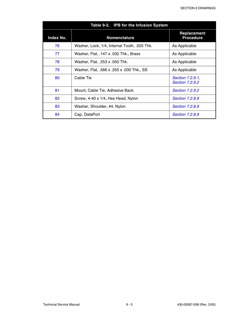
SECTION 9 DRAWINGS
Technical Service Manual 9 - 5 430-00587-008 (Rev. 2/05)
76 Washer, Lock, 1/4, Internal Tooth, .025 Thk. As Applicable
77 Washer, Flat, .147 x .032 Thk., Brass As Applicable
78 Washer, Flat, .253 x .050 Thk. As Applicable
79 Washer, Flat, .566 x .255 x .030 Thk., SS As Applicable
80 Cable Tie Section 7.2.9.1, Section 7.2.9.2
81 Mount, Cable Tie, Adhesive Back Section 7.2.9.2
82 Screw, 4-40 x 1/4, Hex Head, Nylon Section 7.2.8.9
83 Washer, Shoulder, #4, Nylon Section 7.2.8.9
84 Cap, DataPort Section 7.2.8.9
Table 9-2. IPB for the Infusion System
Index No. NomenclatureReplacement
Procedure

SECTION 9 DRAWINGS
430-00587-008 (Rev. 2/05) 9 - 6 Plum XL Series
This page intentionally left blank.
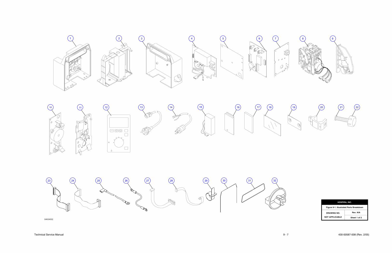
Technical Service Manual 9 - 7 430-00587-008 (Rev. 2/05)
1 3 4 5 6 7 8 9
10 11 12 13 14 15 16 17 18 19 20 21 22
23 24 25 26 27 28 29
04K04002
2
3130 32
HOSPIRA, INC.
Figure 9-1. Illustrated Parts Breakdown
DRAWING NO.
NOT APPLICABLE
Rev. N/A
Sheet 1 of 2

430-00587-008 (Rev. 2/05) 9 - 8 Plum XL Series
SECTION 9 DRAWINGS
This page intentionally left blank.
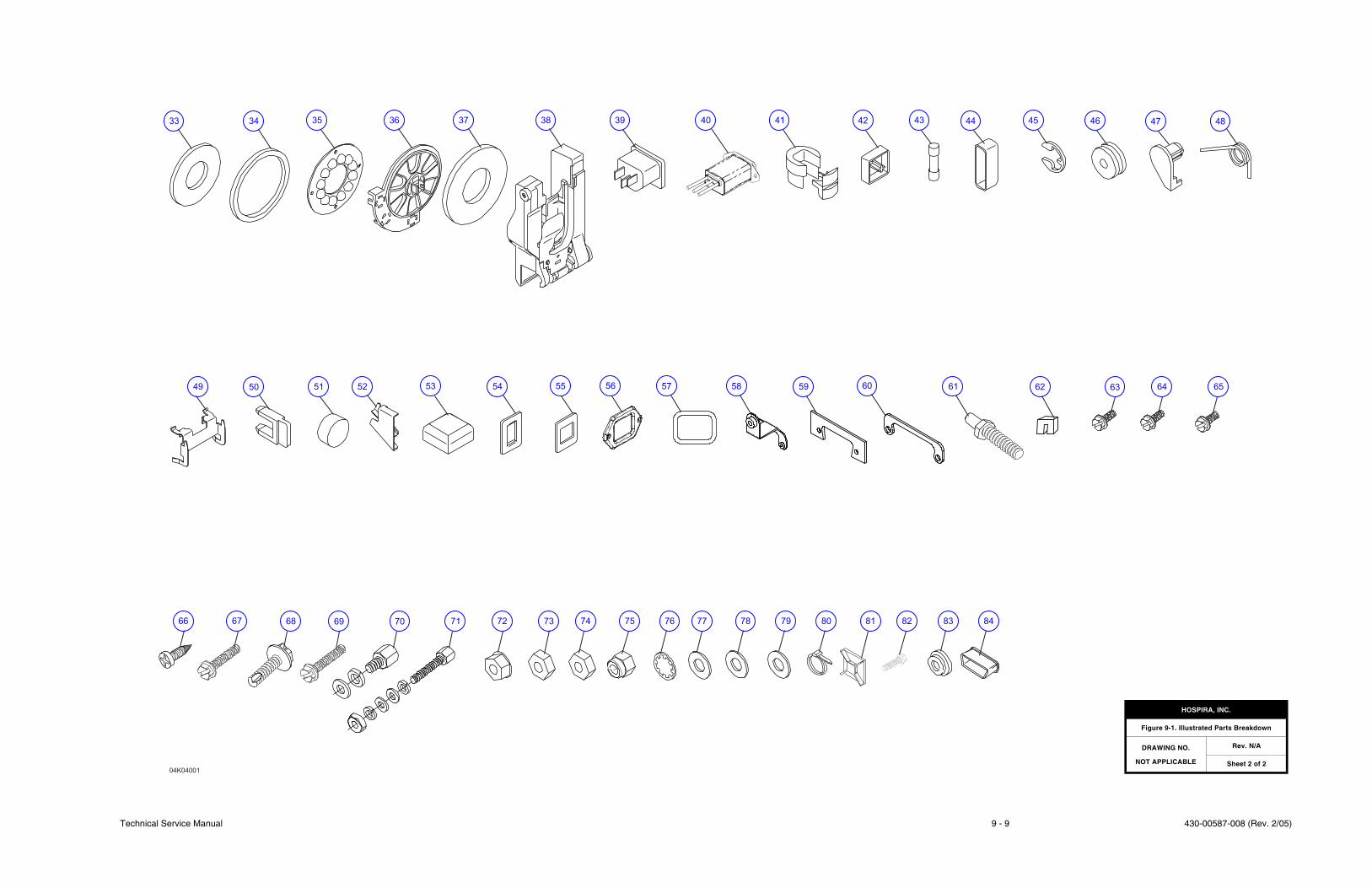
Technical Service Manual 9 - 9 430-00587-008 (Rev. 2/05)
04K04001
5352515049 6057565554
35 36 37 38 39 40 41 44 45 46 47
58 59
42 43
686766
64636261
69 70 71 72 73 74 75 76 77 78 79
33 34
83828180
48
65
84
HOSPIRA, INC.
Figure 9-1. Illustrated Parts Breakdown
DRAWING NO.
NOT APPLICABLE
Rev. N/A
Sheet 2 of 2

430-00587-008 (Rev. 2/05) 9 - 10 Plum XL Series
SECTION 9 DRAWINGS
This page intentionally left blank.
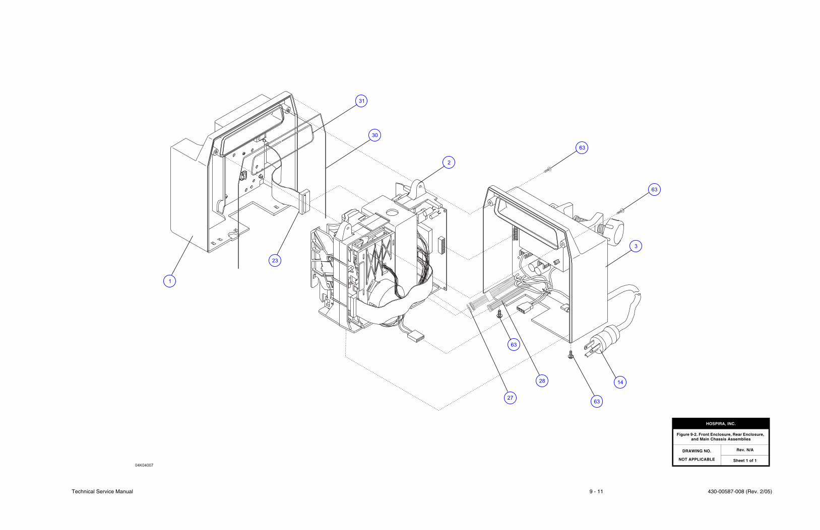
Technical Service Manual 9 - 11 430-00587-008 (Rev. 2/05)
04K04007
30
2
3
63
63
31
1428
27
1
23
63
63
HOSPIRA, INC.
Figure 9-2. Front Enclosure, Rear Enclosure, and Main Chassis Assemblies
DRAWING NO.
NOT APPLICABLE
Rev. N/A
Sheet 1 of 1

430-00587-008 (Rev. 2/05) 9 - 12 Plum XL Series
SECTION 9 DRAWINGS
This page intentionally left blank.

Technical Service Manual 9 - 13 430-00587-008 (Rev. 2/05)
33
34
32
35
12
1
42
51
3650
7
66
23
04K03002
62
62
37
HOSPIRA, INC.
Figure 9-3. Front Enclosure Assembly
DRAWING NO.
NOT APPLICABLE
Rev. N/A
Sheet 1 of 1

430-00587-008 (Rev. 2/05) 9 - 14 Plum XL Series
SECTION 9 DRAWINGS
This page intentionally left blank.
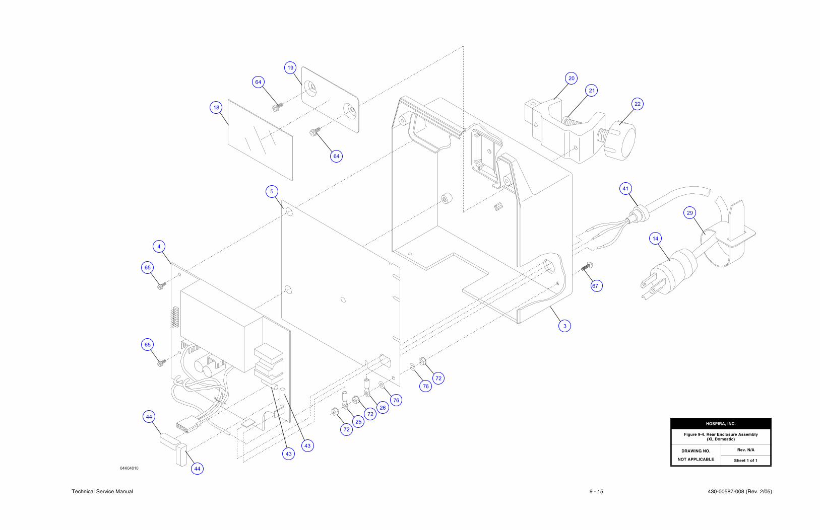
Technical Service Manual 9 - 15 430-00587-008 (Rev. 2/05)
04K04010
64
18
19
5
4
65
44
41
43
25
76
72
3
67
14
29
21
22
20
64
65
44
43
72
72
26
76
HOSPIRA, INC.
Figure 9-4. Rear Enclosure Assembly (XL Domestic)
DRAWING NO.
NOT APPLICABLE
Rev. N/A
Sheet 1 of 1

430-00587-008 (Rev. 2/05) 9 - 16 Plum XL Series
SECTION 9 DRAWINGS
This page intentionally left blank.
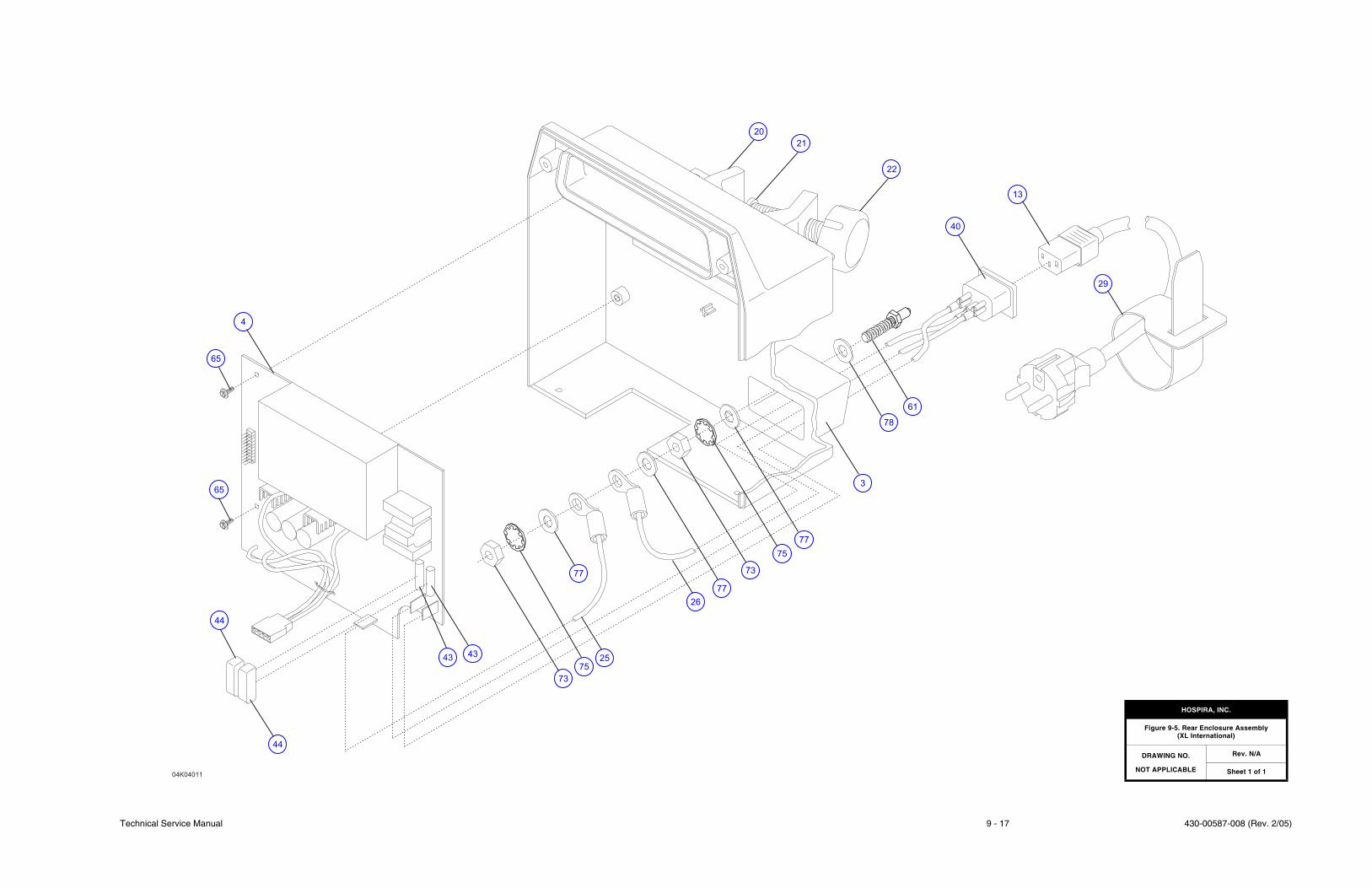
Technical Service Manual 9 - 17 430-00587-008 (Rev. 2/05)
04K04011
21
77
78
29
61
3
73
2543
44
40
13
22
20
65
4
65
44
43
73
77
77
26
75
75
HOSPIRA, INC.
Figure 9-5. Rear Enclosure Assembly (XL International)
DRAWING NO.
NOT APPLICABLE
Rev. N/A
Sheet 1 of 1

430-00587-008 (Rev. 2/05) 9 - 18 Plum XL Series
SECTION 9 DRAWINGS
This page intentionally left blank.
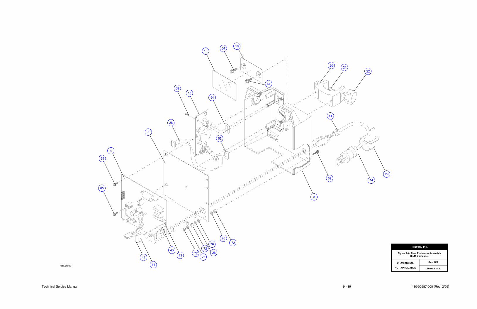
Technical Service Manual 9 - 19 430-00587-008 (Rev. 2/05)
20
14
21
19
10
68
65
65
3
4
43
44
44
43
76
72
72
25
5
72
26
76
28
54
55
1864
64
22
41
29
69
04K04005
HOSPIRA, INC.
Figure 9-6. Rear Enclosure Assembly (XLM Domestic)
DRAWING NO.
NOT APPLICABLE
Rev. N/A
Sheet 1 of 1

430-00587-008 (Rev. 2/05) 9 - 20 Plum XL Series
SECTION 9 DRAWINGS
This page intentionally left blank.
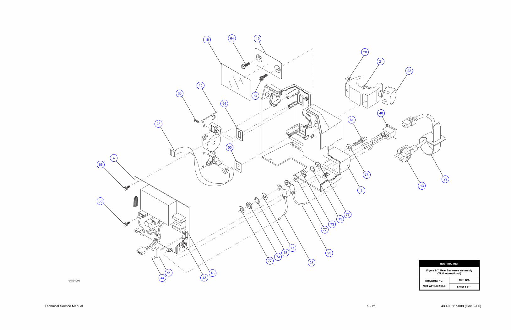
Technical Service Manual 9 - 21 430-00587-008 (Rev. 2/05)
28
68
10
18
61
65
73
20
21
22
78
13
29
75
75
77
43
43
7725
77
73
4
64 19
54
64
55
40
3
25
77
44
4404K04006
65
HOSPIRA, INC.
Figure 9-7. Rear Enclosure Assembly (XLM International)
DRAWING NO.
NOT APPLICABLE
Rev. N/A
Sheet 1 of 1

430-00587-008 (Rev. 2/05) 9 - 22 Plum XL Series
SECTION 9 DRAWINGS
This page intentionally left blank.
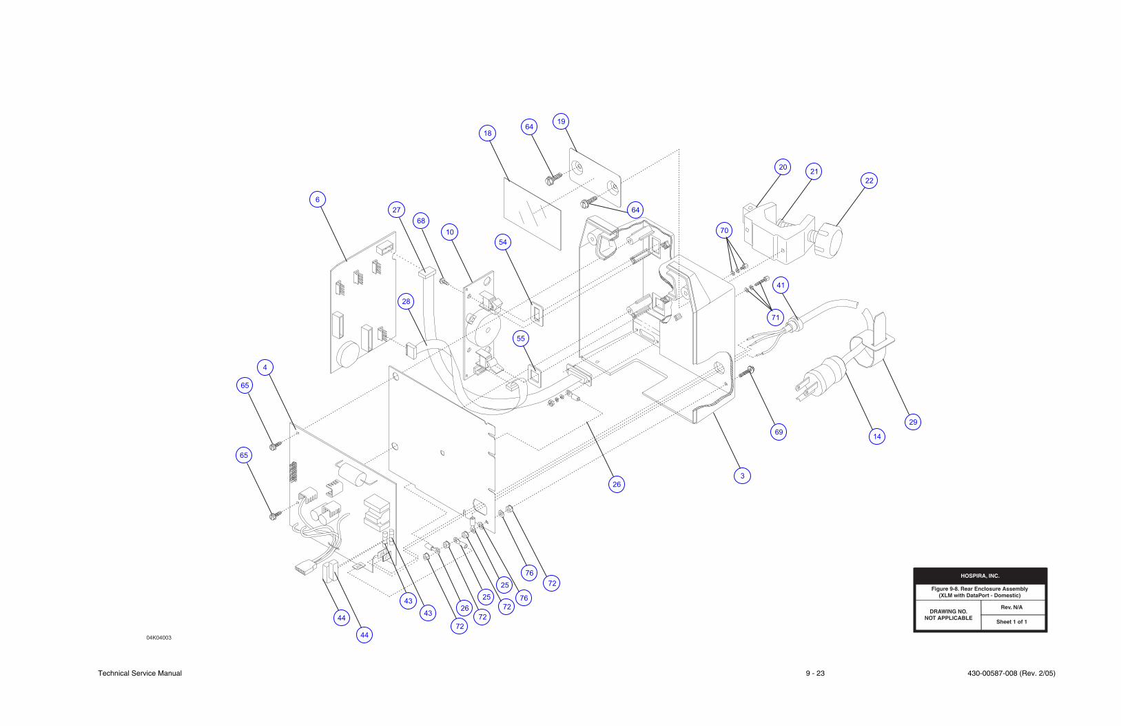
Technical Service Manual 9 - 23 430-00587-008 (Rev. 2/05)
HOSPIRA, INC.
Figure 9-8. Rear Enclosure Assembly (XLM with DataPort - Domestic)
DRAWING NO.NOT APPLICABLE
REV. N/A
SHEET 1 OF 1
20
14
21
19
7010
68
27
6
65
65
3
26
4
43
44
44
43
76
72
72
26
72
7625
72
25
28
54
55
1864
64
22
71
41
29
69
04K04003
DRAWING NO.NOT APPLICABLE
Rev. N/A
Sheet 1 of 1
HOSPIRA, INC.
Figure 9-8. Rear Enclosure Assembly(XLM with DataPort - Domestic)

430-00587-008 (Rev. 2/05) 9 - 24 Plum XL Series
SECTION 9 DRAWINGS
This page intentionally left blank.
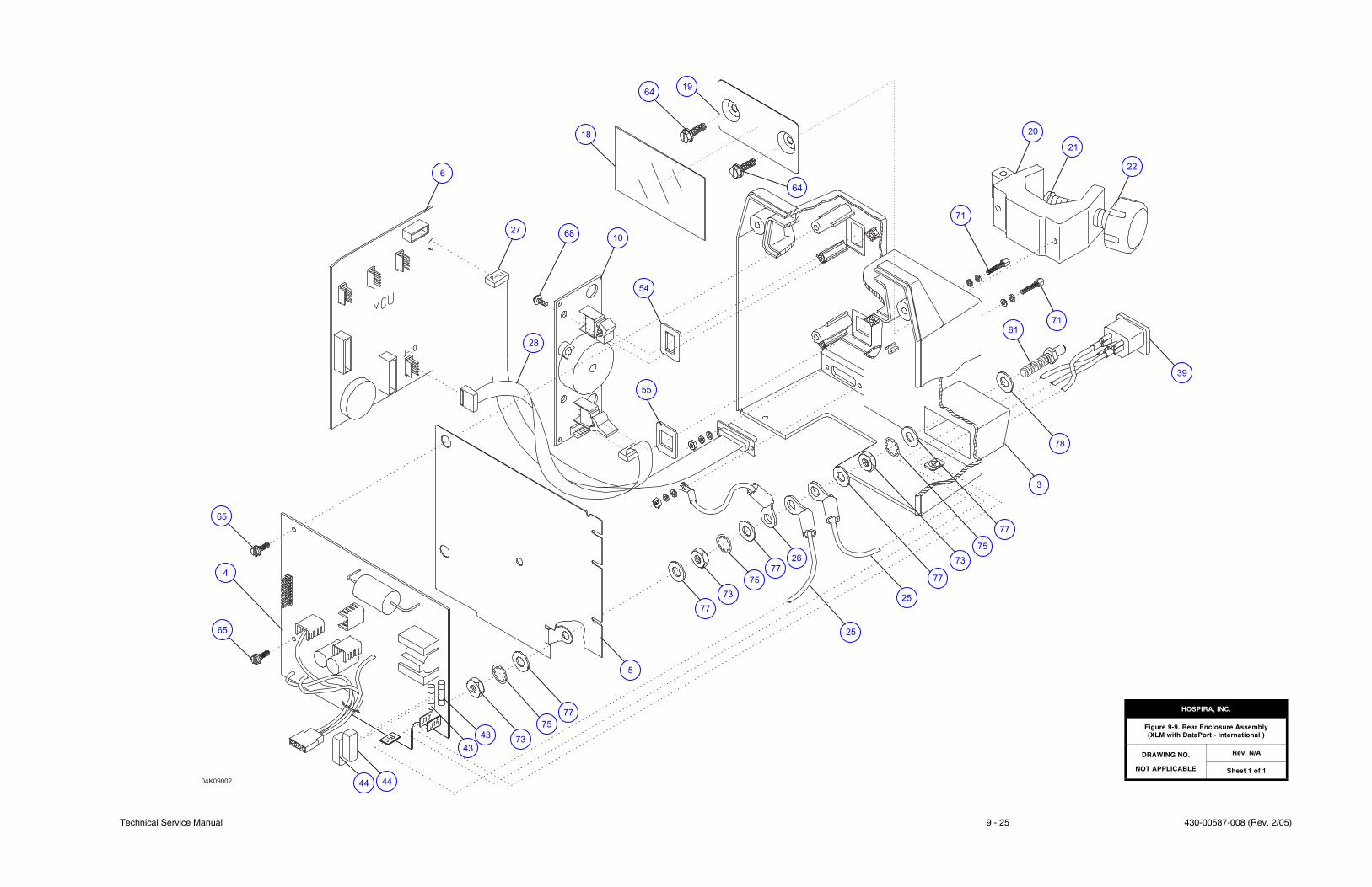
Technical Service Manual 9 - 25 430-00587-008 (Rev. 2/05)
04K09002
27
6
18
64
1068
54
28
55
4
65
5
43
25
44
75
77
19
71
25
3
78
71
61
39
22
21
20
77
75
73
77
26
75
73
77
77
44
43
64
65
73
HOSPIRA, INC.
Figure 9-9. Rear Enclosure Assembly (XLM with DataPort - International )
DRAWING NO.
NOT APPLICABLE
Rev. N/A
Sheet 1 of 1

430-00587-008 (Rev. 2/05) 9 - 26 Plum XL Series
SECTION 9 DRAWINGS
This page intentionally left blank.
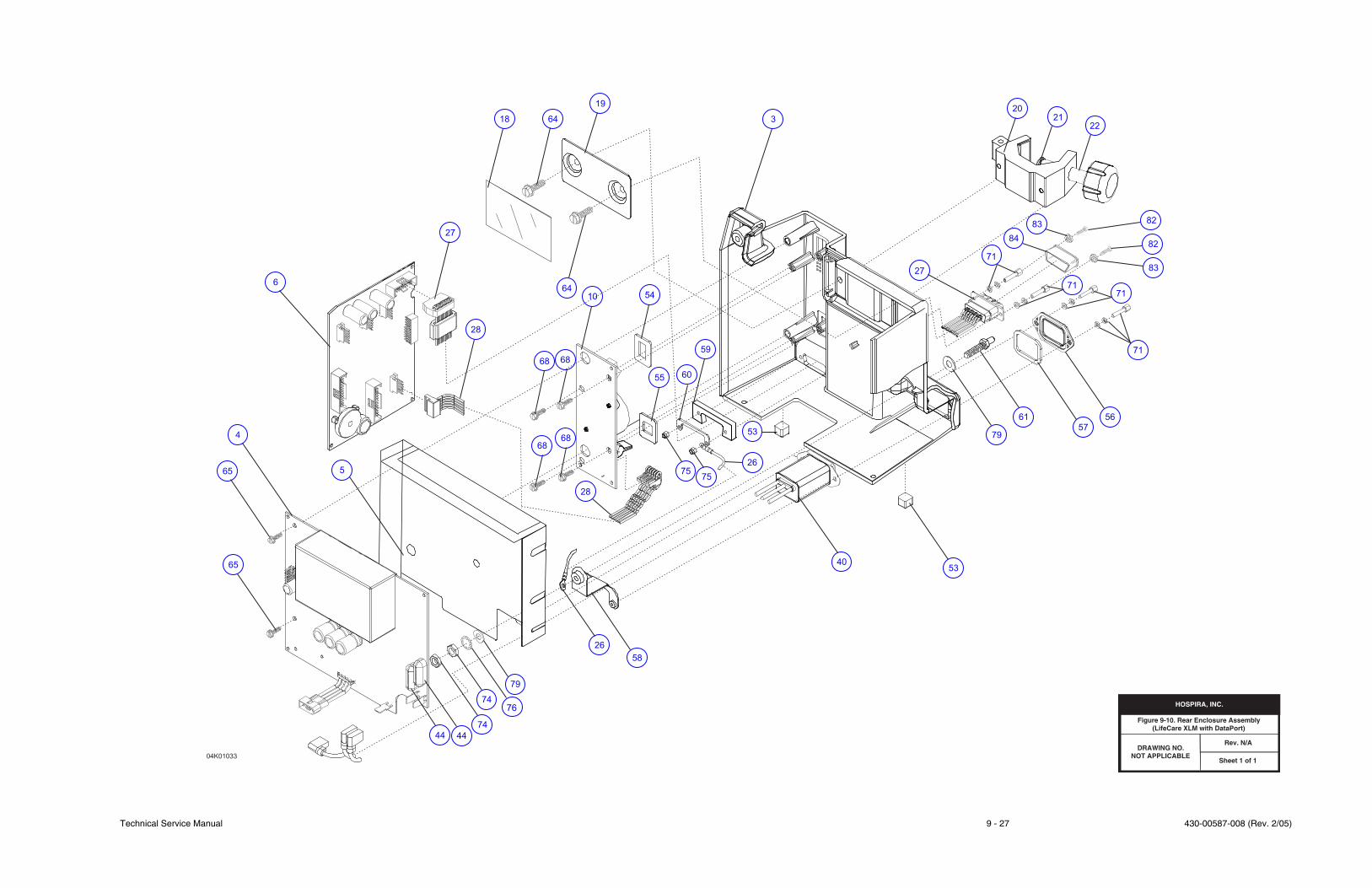
Technical Service Manual 9 - 27 430-00587-008 (Rev. 2/05)
HOSPIRA, INC.
Figure 9-10. Rear Enclosure Assembly (Lifecare XLM with DataPort)
DRAWING NO.NOT APPLICABLE
REV. N/A
SHEET 1 OF 1
04K01033
65
4
65
5
6
28
68
68
68
68
10 54
59
55
18 64
19
3
20
21
22
64
27
71
60
56
57
61
79
71
71
71
5340
53
58
74
4444
74
75
28
75
27
26
26
84
8382
82
83
79
76
DRAWING NO.NOT APPLICABLE
Rev. N/A
Sheet 1 of 1
HOSPIRA, INC.
Figure 9-10. Rear Enclosure Assembly(LifeCare XLM with DataPort)

430-00587-008 (Rev. 2/05) 9 - 28 Plum XL Series
SECTION 9 DRAWINGS
This page intentionally left blank.
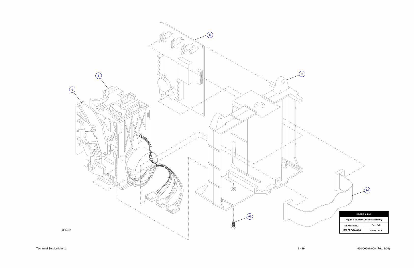
Technical Service Manual 9 - 29 430-00587-008 (Rev. 2/05)
04K04012
24
63
6
8
9
2
HOSPIRA, INC.
Figure 9-11. Main Chassis Assembly
DRAWING NO.
NOT APPLICABLE
Rev. N/A
Sheet 1 of 1

430-00587-008 (Rev. 2/05) 9 - 30 Plum XL Series
SECTION 9 DRAWINGS
This page intentionally left blank.
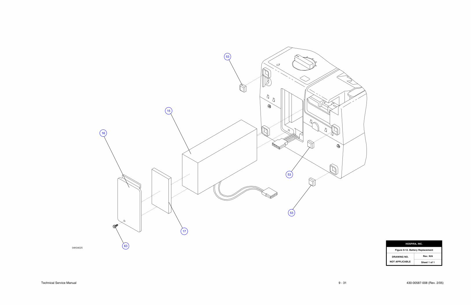
Technical Service Manual 9 - 31 430-00587-008 (Rev. 2/05)
04K04025
16
15
63
17
53
53
53
HOSPIRA, INC.
Figure 9-12. Battery Replacement
DRAWING NO.
NOT APPLICABLE
Rev. N/A
Sheet 1 of 1

430-00587-008 (Rev. 2/05) 9 - 32 Plum XL Series
SECTION 9 DRAWINGS
This page intentionally left blank.
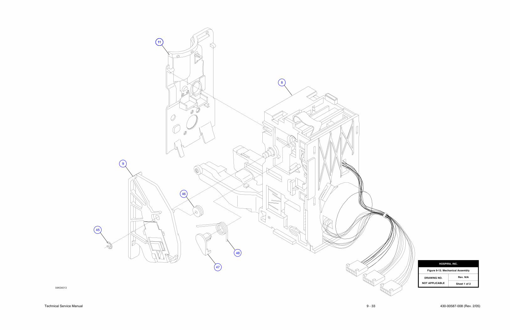
Technical Service Manual 9 - 33 430-00587-008 (Rev. 2/05)
04K04013
45
9
46
11
8
47
11
48
HOSPIRA, INC.
Figure 9-13. Mechanical Assembly
DRAWING NO.
NOT APPLICABLE
Rev. N/A
Sheet 1 of 2

430-00587-008 (Rev. 2/05) 9 - 34 Plum XL Series
SECTION 9 DRAWINGS
This page intentionally left blank.
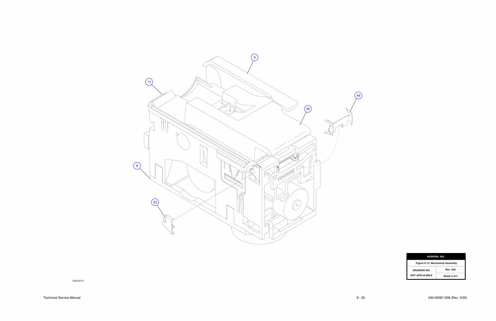
Technical Service Manual 9 - 35 430-00587-008 (Rev. 2/05)
04K04014
52
11
9
8
38
49
HOSPIRA, INC.
Figure 9-13. Mechanical Assembly
DRAWING NO.
NOT APPLICABLE
Rev. N/A
Sheet 2 of 2

430-00587-008 (Rev. 2/05) 9 - 36 Plum XL Series
SECTION 9 DRAWINGS
This page intentionally left blank.
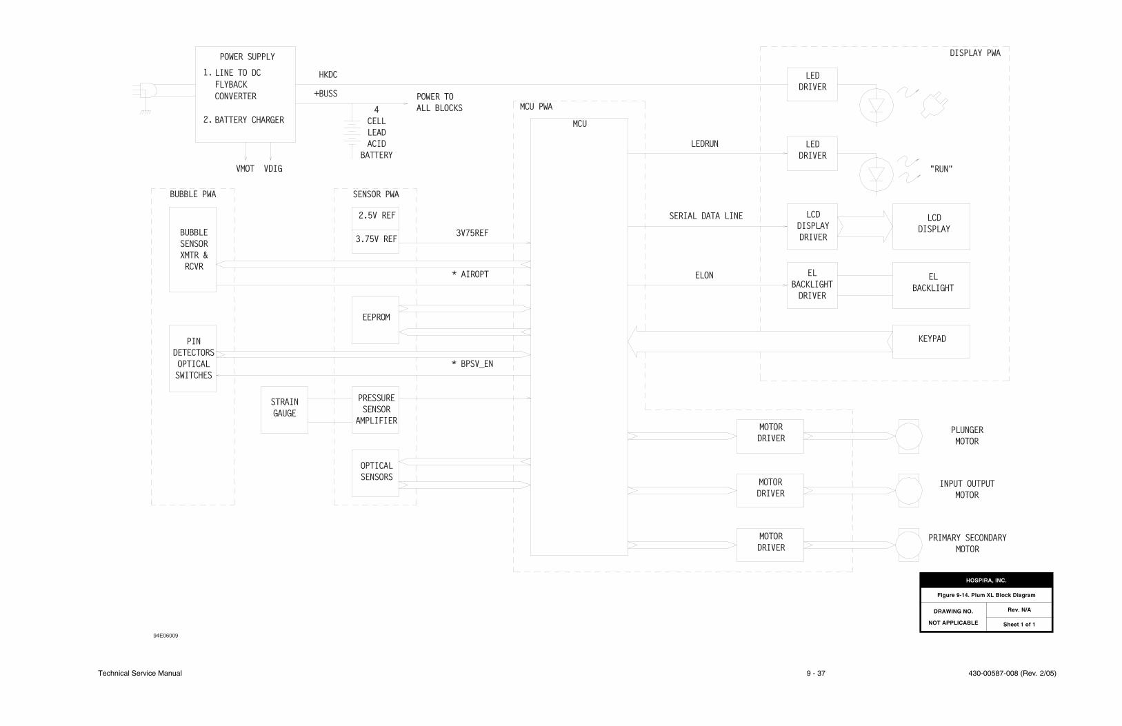
Technical Service Manual 9 - 37 430-00587-008 (Rev. 2/05)
POWER SUPPLY
HKDC
+BUSS
4
CELL
LEAD
ACID
BATTERY
POWER TO
ALL BLOCKS
BUBBLE PWA SENSOR PWA
BUBBLE
SENSOR
XMTR &
RCVR
2.5V REF
3.75V REF
EEPROM
PIN
DETECTORS
OPTICAL
SWITCHES
STRAIN
GAUGE
PRESSURE
SENSOR
AMPLIFIER
OPTICAL
SENSORS
* BPSV_EN
* AIROPT
3V75REF
MCU PWA
MCU
LEDRUN
LED
DRIVER
LED
DRIVER
SERIAL DATA LINE
ELON
LCD
DISPLAY
DRIVER
EL
BACKLIGHT
DRIVER
DISPLAY PWA
"RUN"
LCD
DISPLAY
EL
BACKLIGHT
KEYPAD
MOTOR
DRIVER
MOTOR
DRIVER
MOTOR
DRIVER
PLUNGER
MOTOR
INPUT OUTPUT
MOTOR
PRIMARY SECONDARY
MOTOR
LINE TO DC
FLYBACK
CONVERTER
BATTERY CHARGER
1.
2.
VMOT VDIG
94E06009
HOSPIRA, INC.
Figure 9-14. Plum XL Block Diagram
DRAWING NO.
NOT APPLICABLE
Rev. N/A
Sheet 1 of 1

430-00587-008 (Rev. 2/05) 9 - 38 Plum XL Series
SECTION 9 DRAWINGS
This page intentionally left blank.

Technical Service Manual 9 - 39 430-00587-008 (Rev. 2/05)
HOSPIRA, INC.
Figure 9-15. MCU PWA Schematic (XL)
DRAWING NO.
249-00530-009
Rev. F
Sheet 1 of 2

430-00587-008 (Rev. 2/05) 9 - 40 Plum XL Series
SECTION 9 DRAWINGS
This page intentionally left blank.
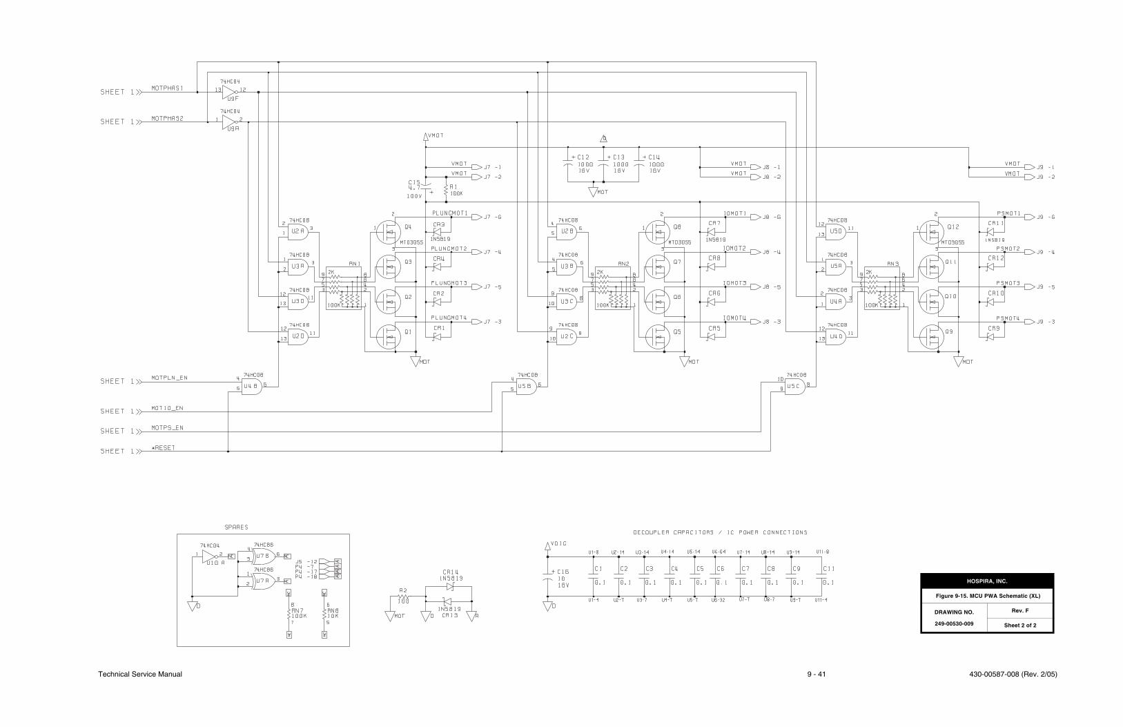
Technical Service Manual 9 - 41 430-00587-008 (Rev. 2/05)
HOSPIRA, INC.
Figure 9-15. MCU PWA Schematic (XL)
DRAWING NO.
249-00530-009
Rev. F
Sheet 2 of 2

430-00587-008 (Rev. 2/05) 9 - 42 Plum XL Series
SECTION 9 DRAWINGS
This page intentionally left blank.
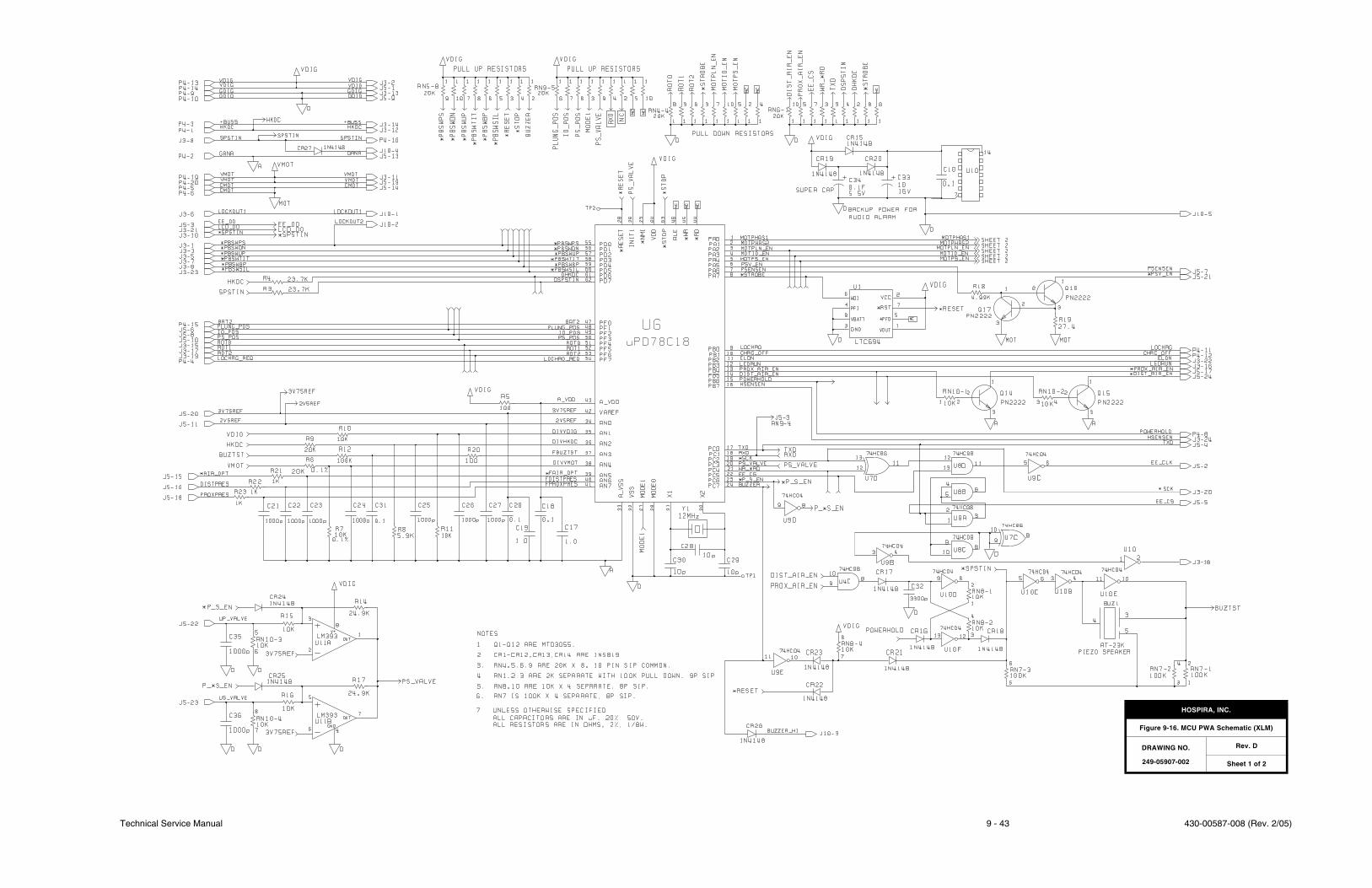
Technical Service Manual 9 - 43 430-00587-008 (Rev. 2/05)
HOSPIRA, INC.
Figure 9-16. MCU PWA Schematic (XLM)
DRAWING NO.
249-05907-002
Rev. D
Sheet 1 of 2

430-00587-008 (Rev. 2/05) 9 - 44 Plum XL Series
SECTION 9 DRAWINGS
This page intentionally left blank.
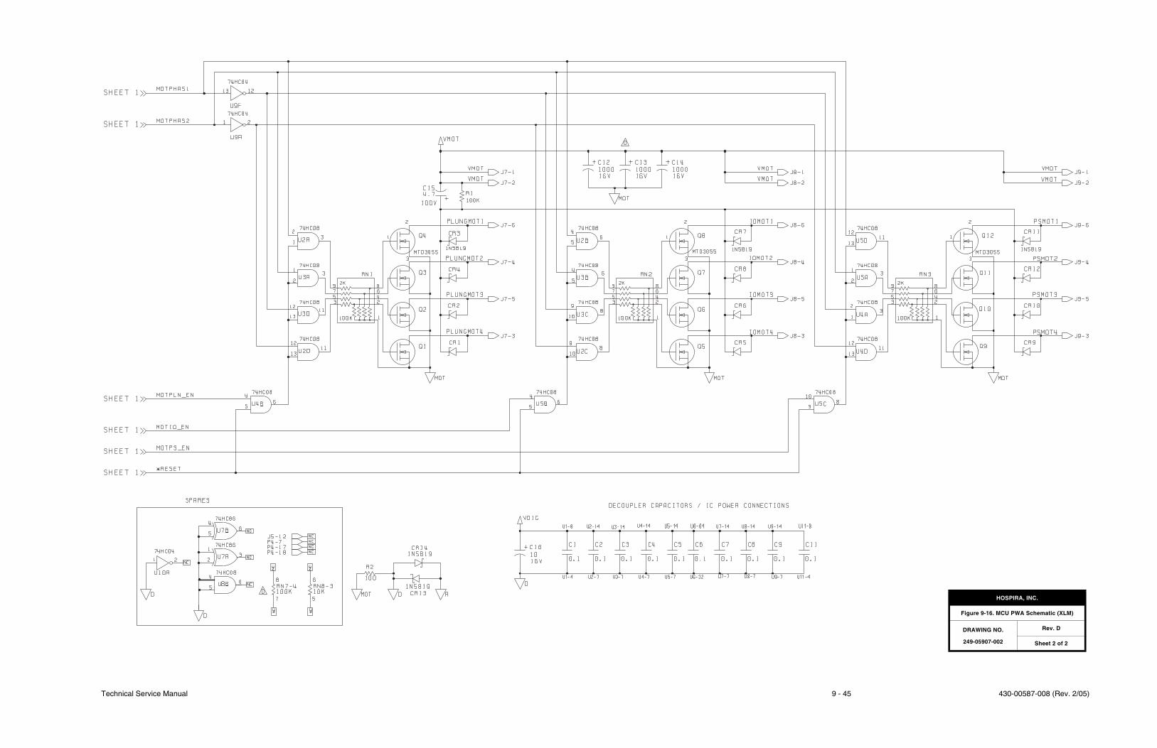
Technical Service Manual 9 - 45 430-00587-008 (Rev. 2/05)
HOSPIRA, INC.
Figure 9-16. MCU PWA Schematic (XLM)
DRAWING NO.
249-05907-002
Rev. D
Sheet 2 of 2

430-00587-008 (Rev. 2/05) 9 - 46 Plum XL Series
SECTION 9 DRAWINGS
This page intentionally left blank.
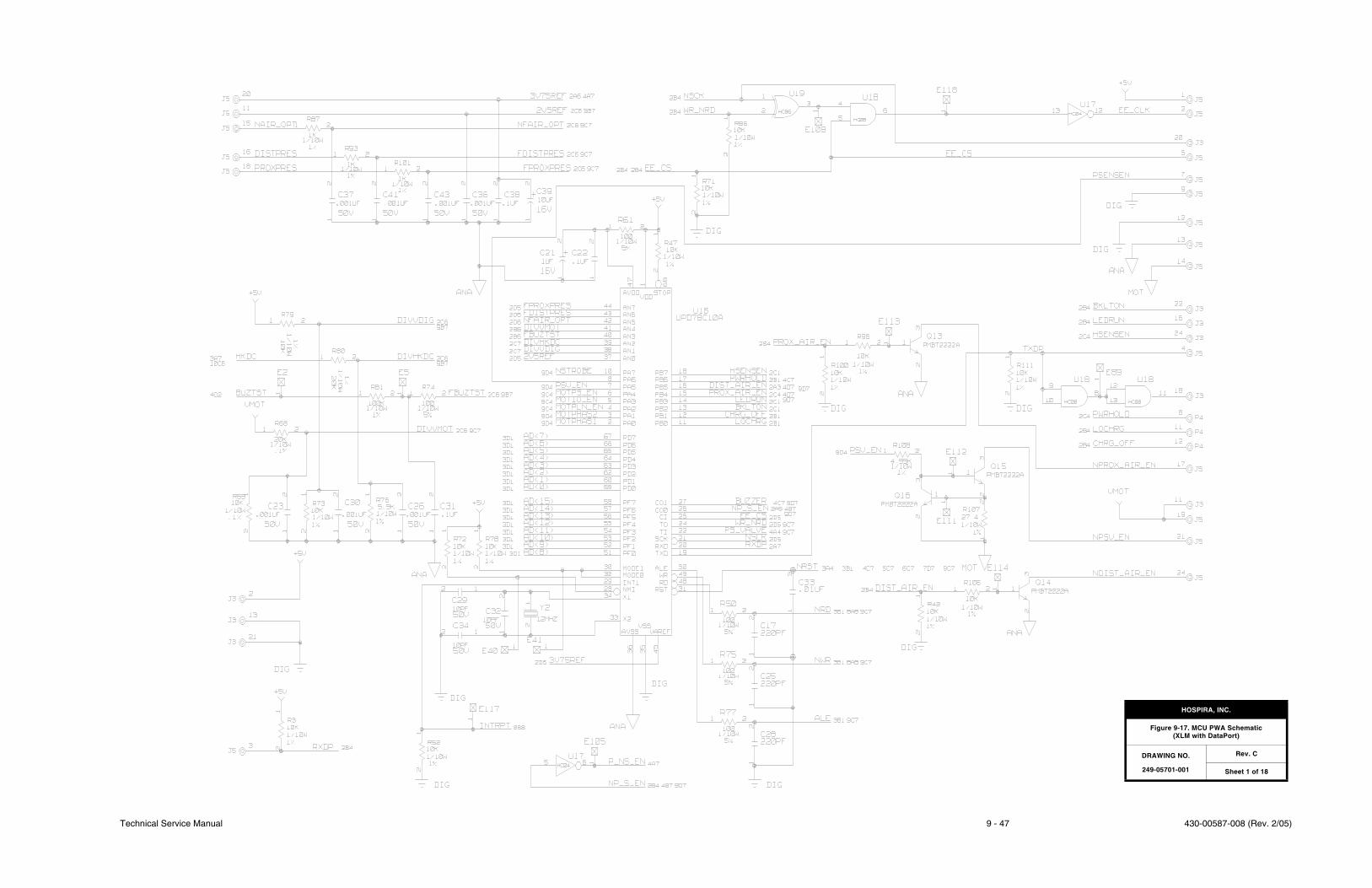
Technical Service Manual 9 - 47 430-00587-008 (Rev. 2/05)
HOSPIRA, INC.
Figure 9-17. MCU PWA Schematic (XLM with DataPort)
DRAWING NO.
249-05701-001
Rev. C
Sheet 1 of 18

430-00587-008 (Rev. 2/05) 9 - 48 Plum XL Series
SECTION 9 DRAWINGS
This page intentionally left blank.
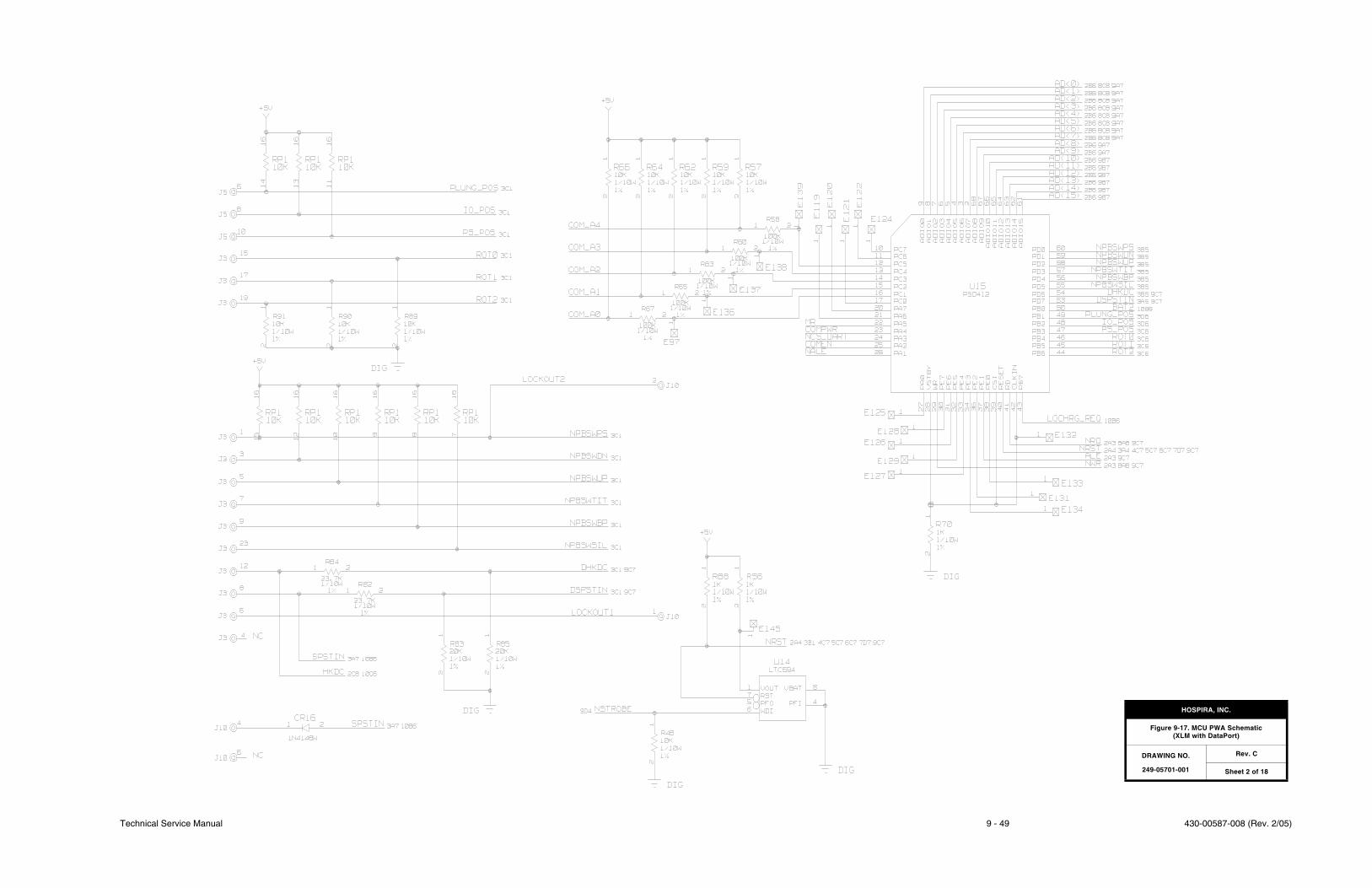
Technical Service Manual 9 - 49 430-00587-008 (Rev. 2/05)
HOSPIRA, INC.
Figure 9-17. MCU PWA Schematic(XLM with DataPort)
DRAWING NO.
249-05701-001
Rev. C
Sheet 2 of 18

430-00587-008 (Rev. 2/05) 9 - 50 Plum XL Series
SECTION 9 DRAWINGS
This page intentionally left blank.
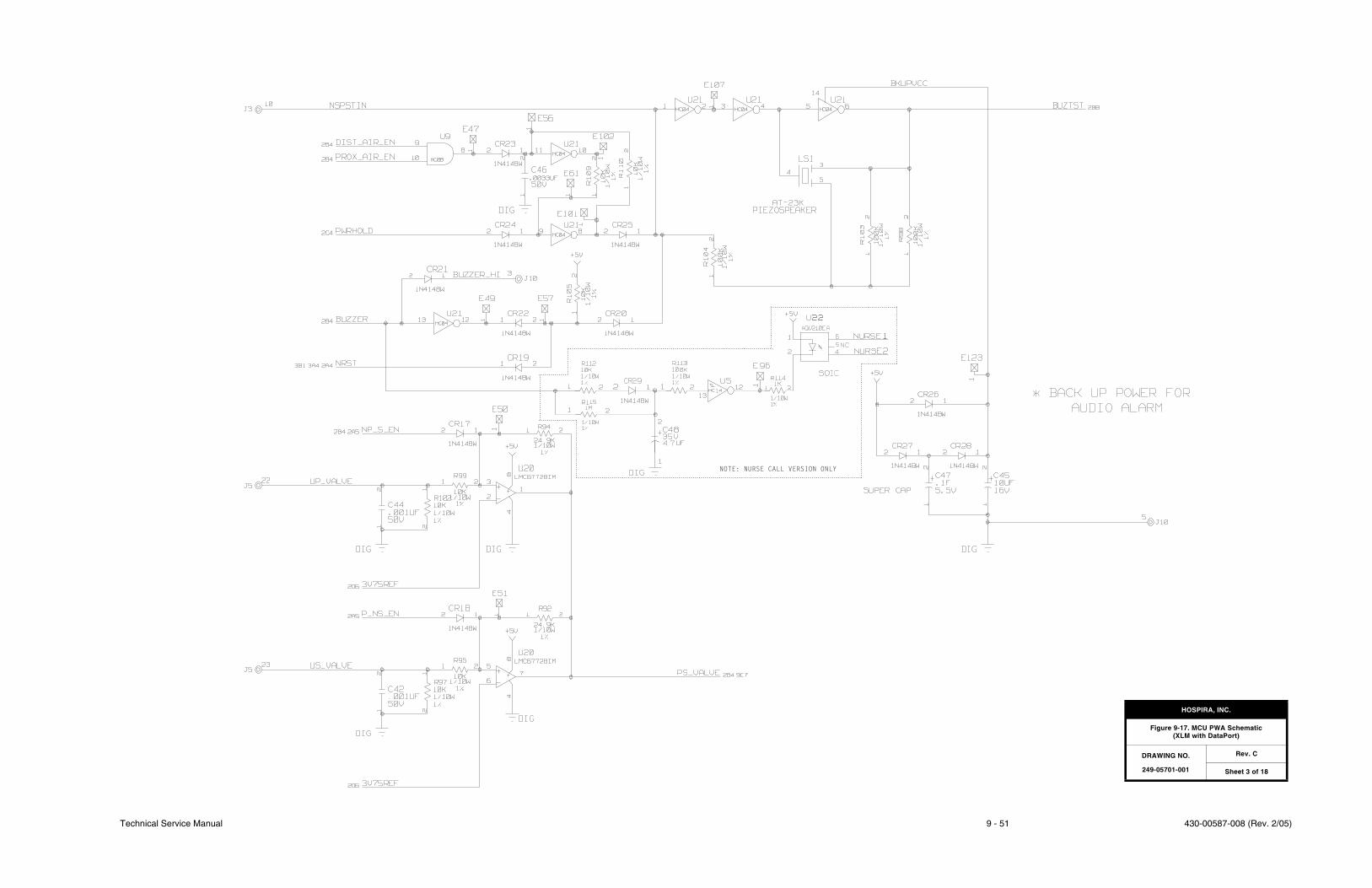
Technical Service Manual 9 - 51 430-00587-008 (Rev. 2/05)
NOTE: NURSE CALL VERSION ONLY
HOSPIRA, INC.
Figure 9-17. MCU PWA Schematic(XLM with DataPort)
DRAWING NO.
249-05701-001
Rev. C
Sheet 3 of 18

430-00587-008 (Rev. 2/05) 9 - 52 Plum XL Series
SECTION 9 DRAWINGS
This page intentionally left blank.

Technical Service Manual 9 - 53 430-00587-008 (Rev. 2/05)
HOSPIRA
Figure 9-17. MCU PWA Schematic(XLM with DataPort)
DRAWING NO.
249-05701-001
Rev. C
Sheet 4 of 18

430-00587-008 (Rev. 2/05) 9 - 54 Plum XL Series
SECTION 9 DRAWINGS
This page intentionally left blank.
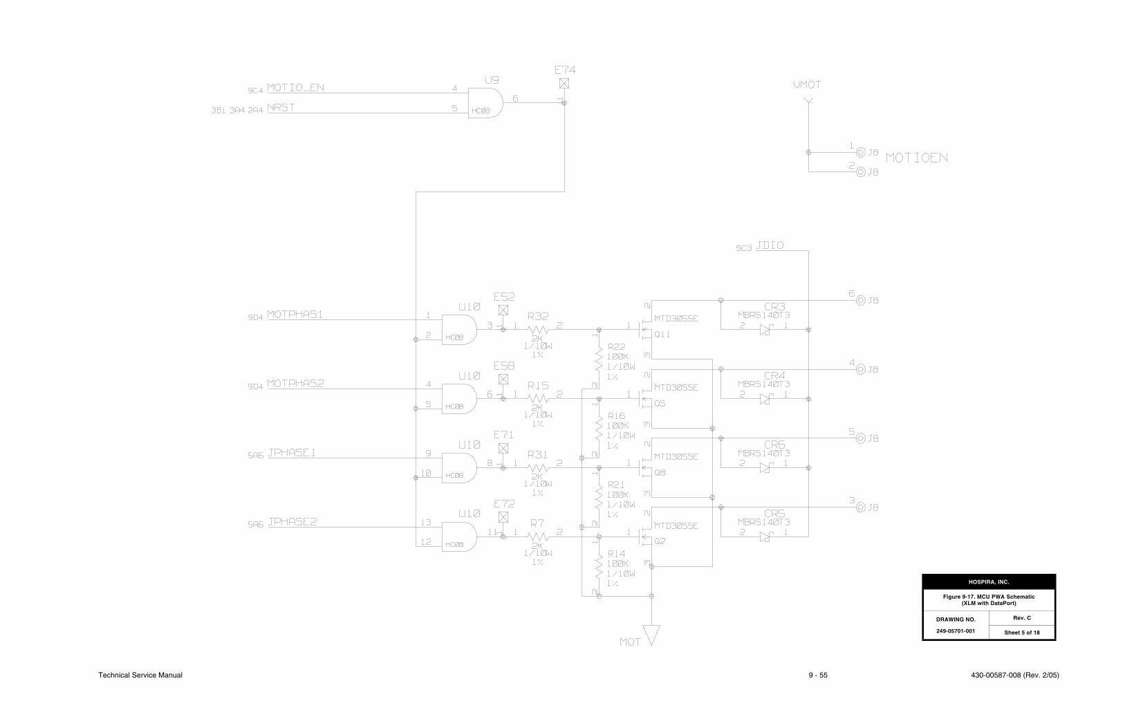
Technical Service Manual 9 - 55 430-00587-008 (Rev. 2/05)
HOSPIRA, INC.
Figure 9-17. MCU PWA Schematic(XLM with DataPort)
DRAWING NO.
249-05701-001
Rev. C
Sheet 5 of 18

430-00587-008 (Rev. 2/05) 9 - 56 Plum XL Series
SECTION 9 DRAWINGS
This page intentionally left blank.

Technical Service Manual 9 - 57 430-00587-008 (Rev. 2/05)
HOSPIRA, INC.
Figure 9-17. MCU PWA Schematic(XLM with DataPort)
DRAWING NO.
249-05701-001
Rev. C
Sheet 6 of 18

430-00587-008 (Rev. 2/05) 9 - 58 Plum XL Series
SECTION 9 DRAWINGS
This page intentionally left blank.
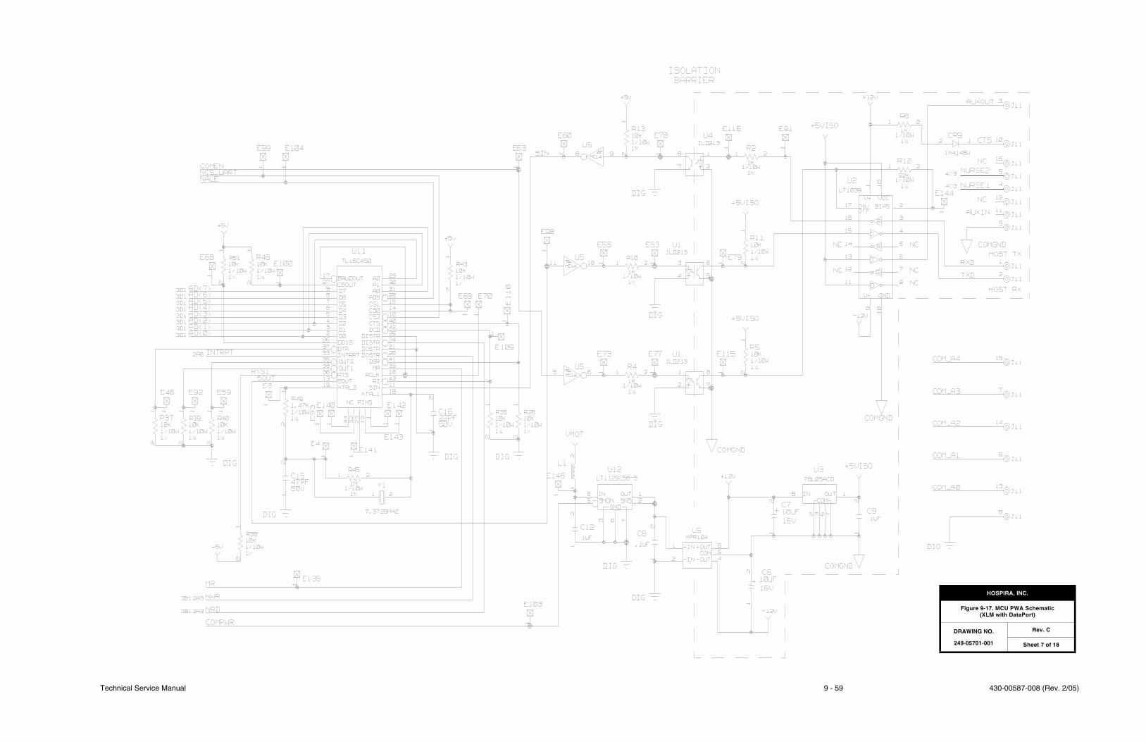
Technical Service Manual 9 - 59 430-00587-008 (Rev. 2/05)
HOSPIRA, INC.
Figure 9-17. MCU PWA Schematic(XLM with DataPort)
DRAWING NO.
249-05701-001
Rev. C
Sheet 7 of 18

430-00587-008 (Rev. 2/05) 9 - 60 Plum XL Series
SECTION 9 DRAWINGS
This page intentionally left blank.
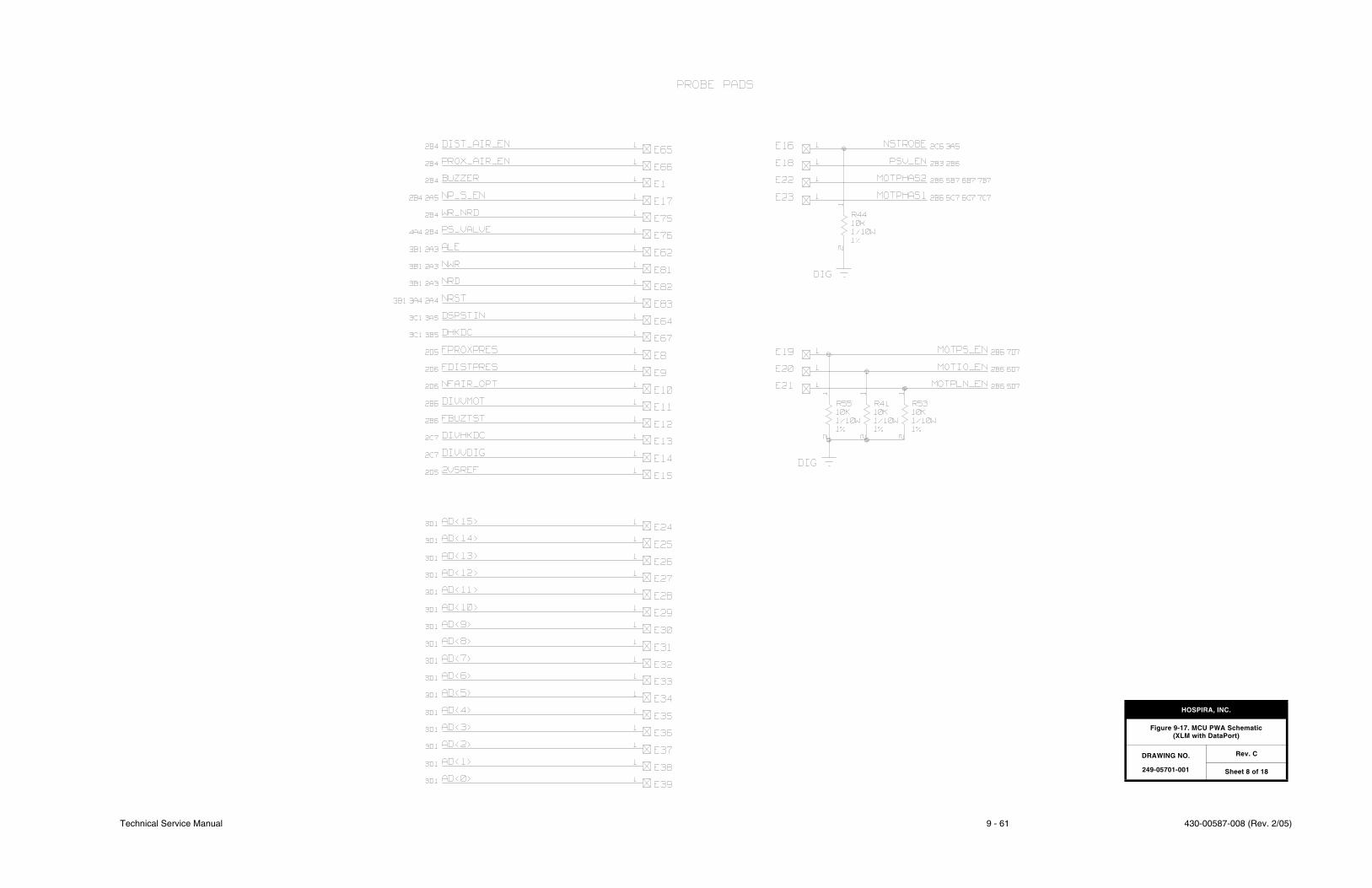
Technical Service Manual 9 - 61 430-00587-008 (Rev. 2/05)
HOSPIRA, INC.
Figure 9-17. MCU PWA Schematic (XLM with DataPort)
DRAWING NO.
249-05701-001
Rev. C
Sheet 8 of 18

430-00587-008 (Rev. 2/05) 9 - 62 Plum XL Series
SECTION 9 DRAWINGS
This page intentionally left blank.
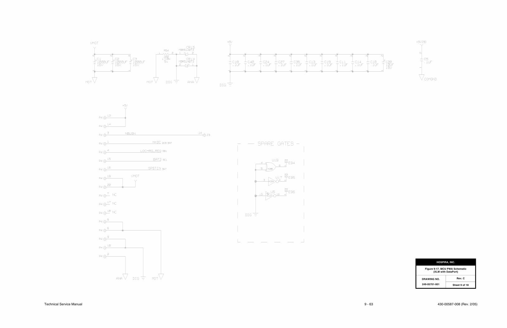
Technical Service Manual 9 - 63 430-00587-008 (Rev. 2/05)
HOSPIRA, INC.
Figure 9-17. MCU PWA Schematic(XLM with DataPort)
DRAWING NO.
249-05701-001
Rev. C
Sheet 9 of 18

430-00587-008 (Rev. 2/05) 9 - 64 Plum XL Series
SECTION 9 DRAWINGS
This page intentionally left blank.
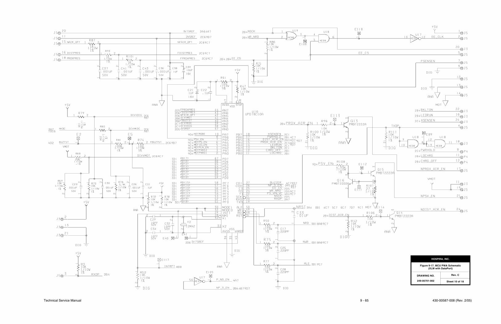
Technical Service Manual 9 - 65 430-00587-008 (Rev. 2/05)
HOSPIRA, INC.
Figure 9-17. MCU PWA Schematic(XLM with DataPort)
DRAWING NO.
249-05701-002
Rev. C
Sheet 10 of 18

430-00587-008 (Rev. 2/05) 9 - 66 Plum XL Series
SECTION 9 DRAWINGS
This page intentionally left blank.
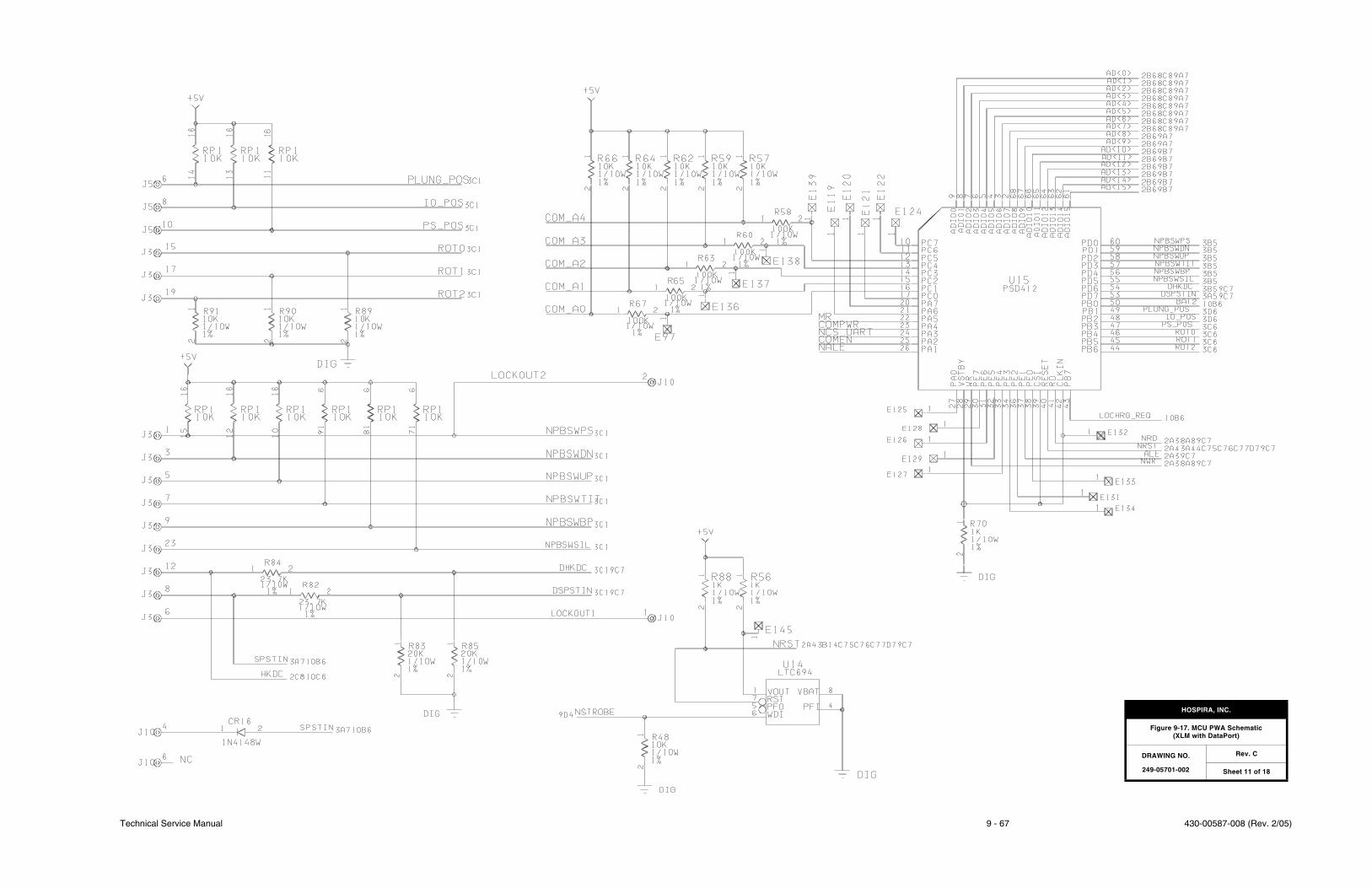
Technical Service Manual 9 - 67 430-00587-008 (Rev. 2/05)
HOSPIRA, INC.
Figure 9-17. MCU PWA Schematic(XLM with DataPort)
DRAWING NO.
249-05701-002
Rev. C
Sheet 11 of 18

430-00587-008 (Rev. 2/05) 9 - 68 Plum XL Series
SECTION 9 DRAWINGS
This page intentionally left blank.

Technical Service Manual 9 - 69 430-00587-008 (Rev. 2/05)
HOSPIRA, INC.
Figure 9-17. MCU PWA Schematic(XLM with DataPort)
DRAWING NO.
249-05701-002
Rev. C
Sheet 12 of 18

430-00587-008 (Rev. 2/05) 9 - 70 Plum XL Series
SECTION 9 DRAWINGS
This page intentionally left blank.
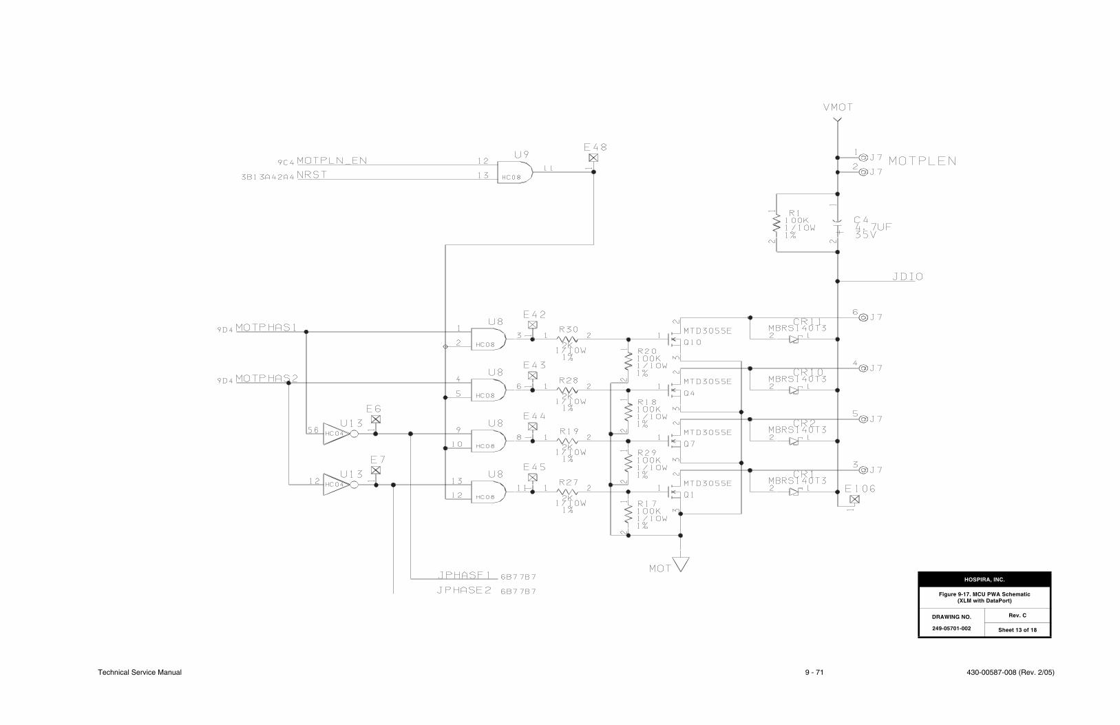
Technical Service Manual 9 - 71 430-00587-008 (Rev. 2/05)
HOSPIRA, INC.
Figure 9-17. MCU PWA Schematic(XLM with DataPort)
DRAWING NO.
249-05701-002
Rev. C
Sheet 13 of 18

430-00587-008 (Rev. 2/05) 9 - 72 Plum XL Series
SECTION 9 DRAWINGS
This page intentionally left blank.
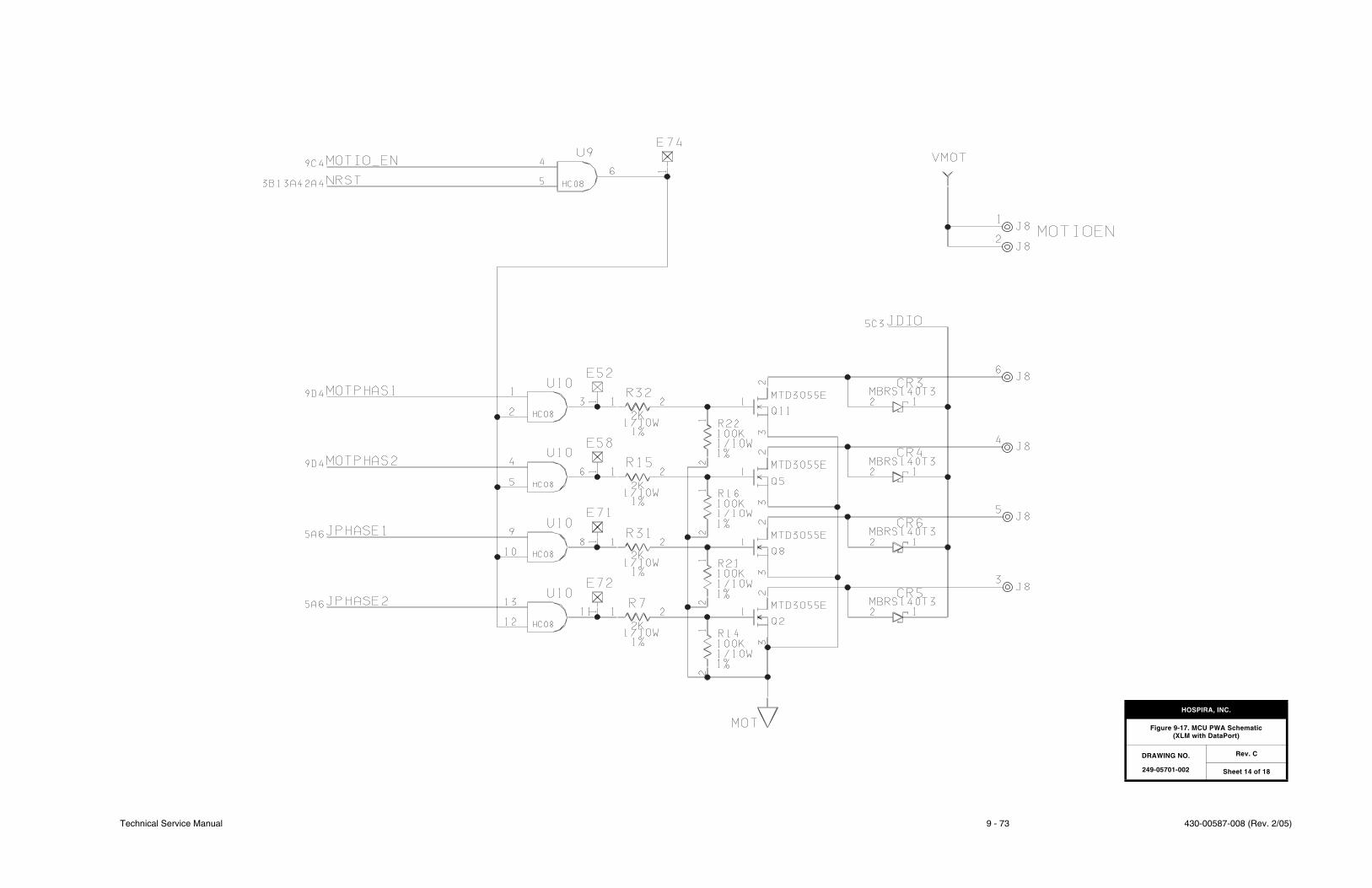
Technical Service Manual 9 - 73 430-00587-008 (Rev. 2/05)
HOSPIRA, INC.
Figure 9-17. MCU PWA Schematic(XLM with DataPort)
DRAWING NO.
249-05701-002
Rev. C
Sheet 14 of 18

430-00587-008 (Rev. 2/05) 9 - 74 Plum XL Series
SECTION 9 DRAWINGS
This page intentionally left blank.

Technical Service Manual 9 - 75 430-00587-008 (Rev. 2/05)
HOSPIRA, INC.
Figure 9-17. MCU PWA Schematic(XLM with DataPort)
DRAWING NO.
249-05701-002
Rev. C
Sheet 15 of 18

430-00587-008 (Rev. 2/05) 9 - 76 Plum XL Series
SECTION 9 DRAWINGS
This page intentionally left blank.
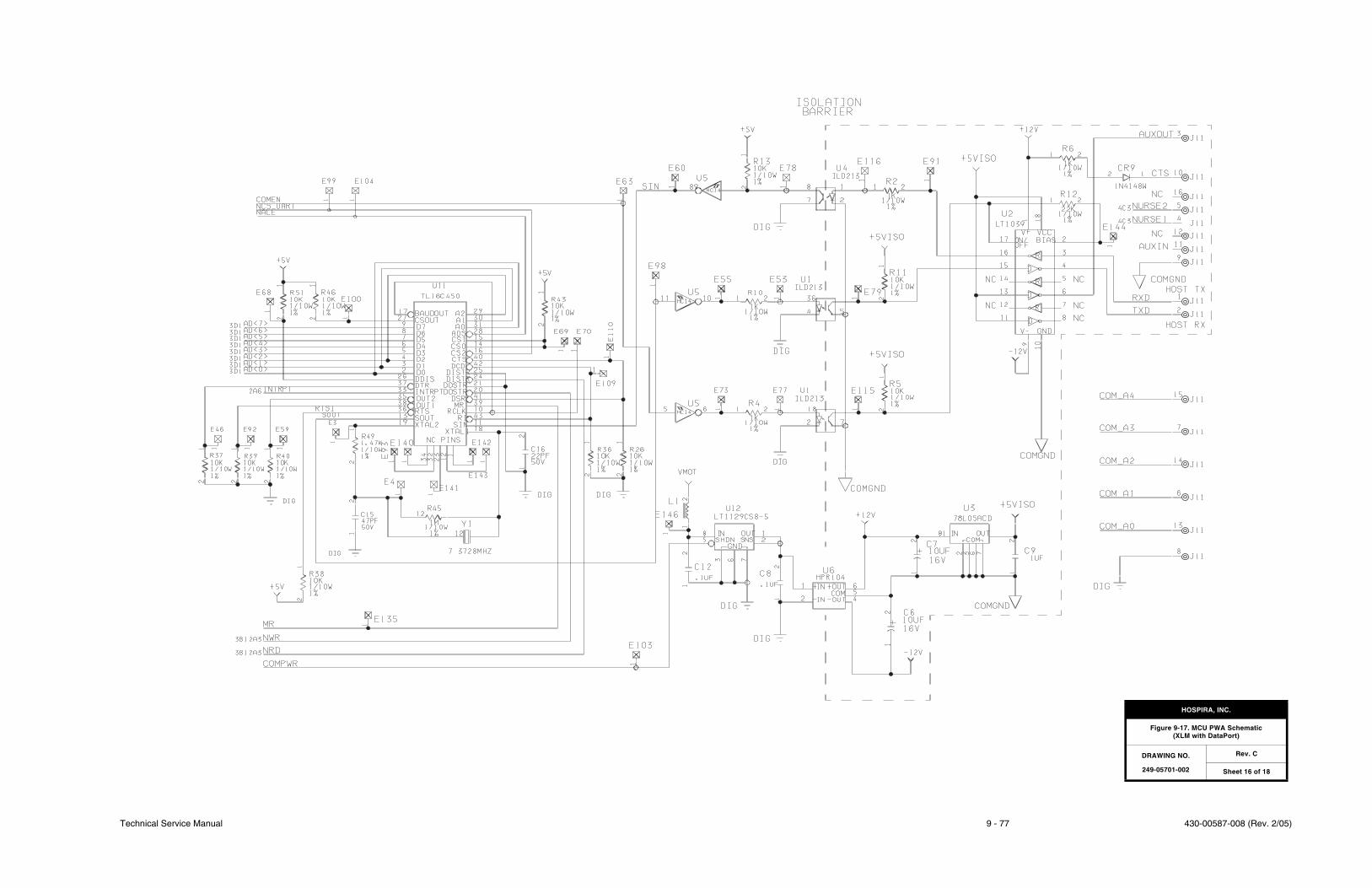
Technical Service Manual 9 - 77 430-00587-008 (Rev. 2/05)
HOSPIRA, INC.
Figure 9-17. MCU PWA Schematic(XLM with DataPort)
DRAWING NO.
249-05701-002
Rev. C
Sheet 16 of 18

430-00587-008 (Rev. 2/05) 9 - 78 Plum XL Series
SECTION 9 DRAWINGS
This page intentionally left blank.
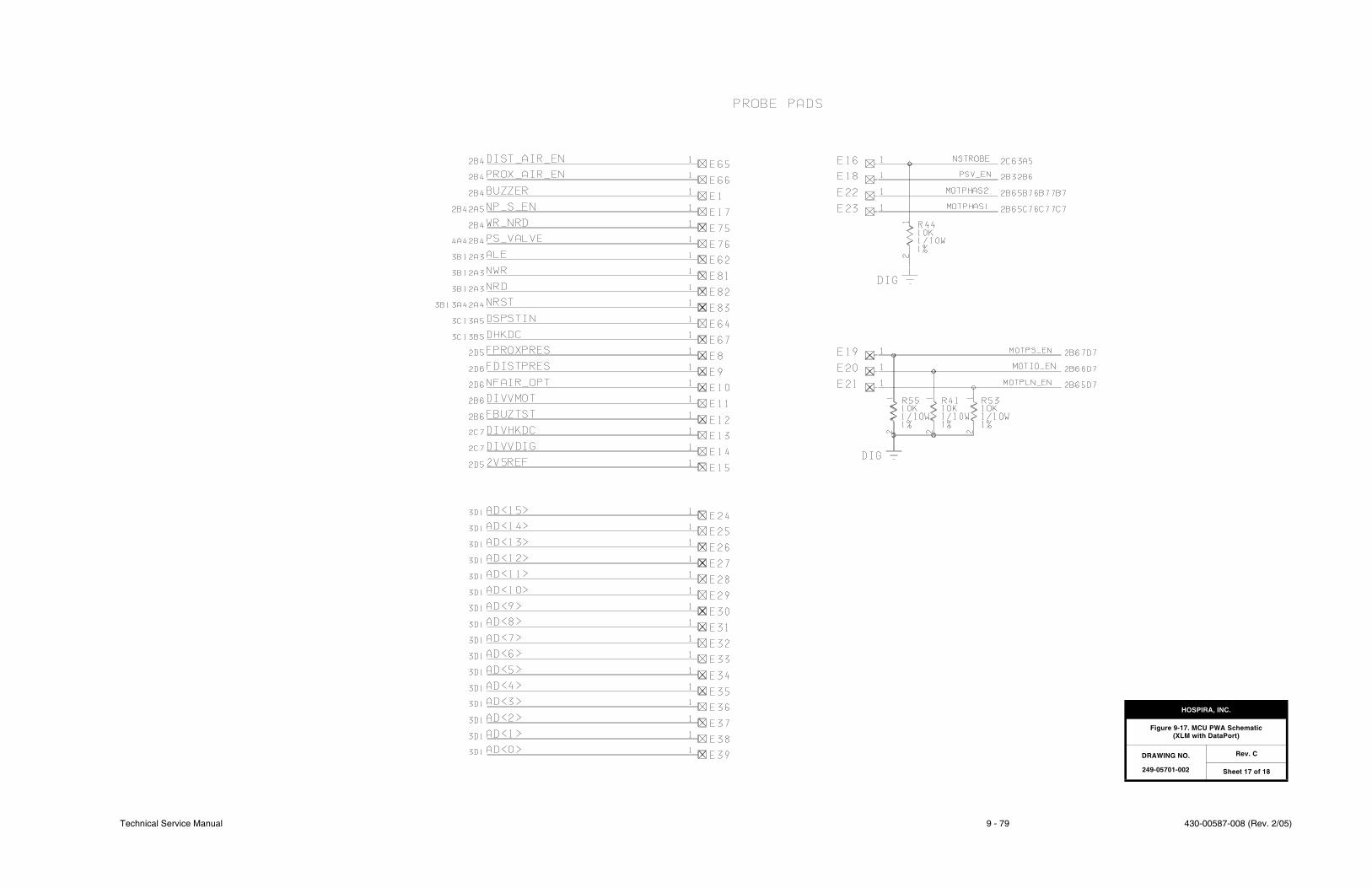
Technical Service Manual 9 - 79 430-00587-008 (Rev. 2/05)
HOSPIRA, INC.
Figure 9-17. MCU PWA Schematic(XLM with DataPort)
DRAWING NO.
249-05701-002
Rev. C
Sheet 17 of 18

430-00587-008 (Rev. 2/05) 9 - 80 Plum XL Series
SECTION 9 DRAWINGS
This page intentionally left blank.
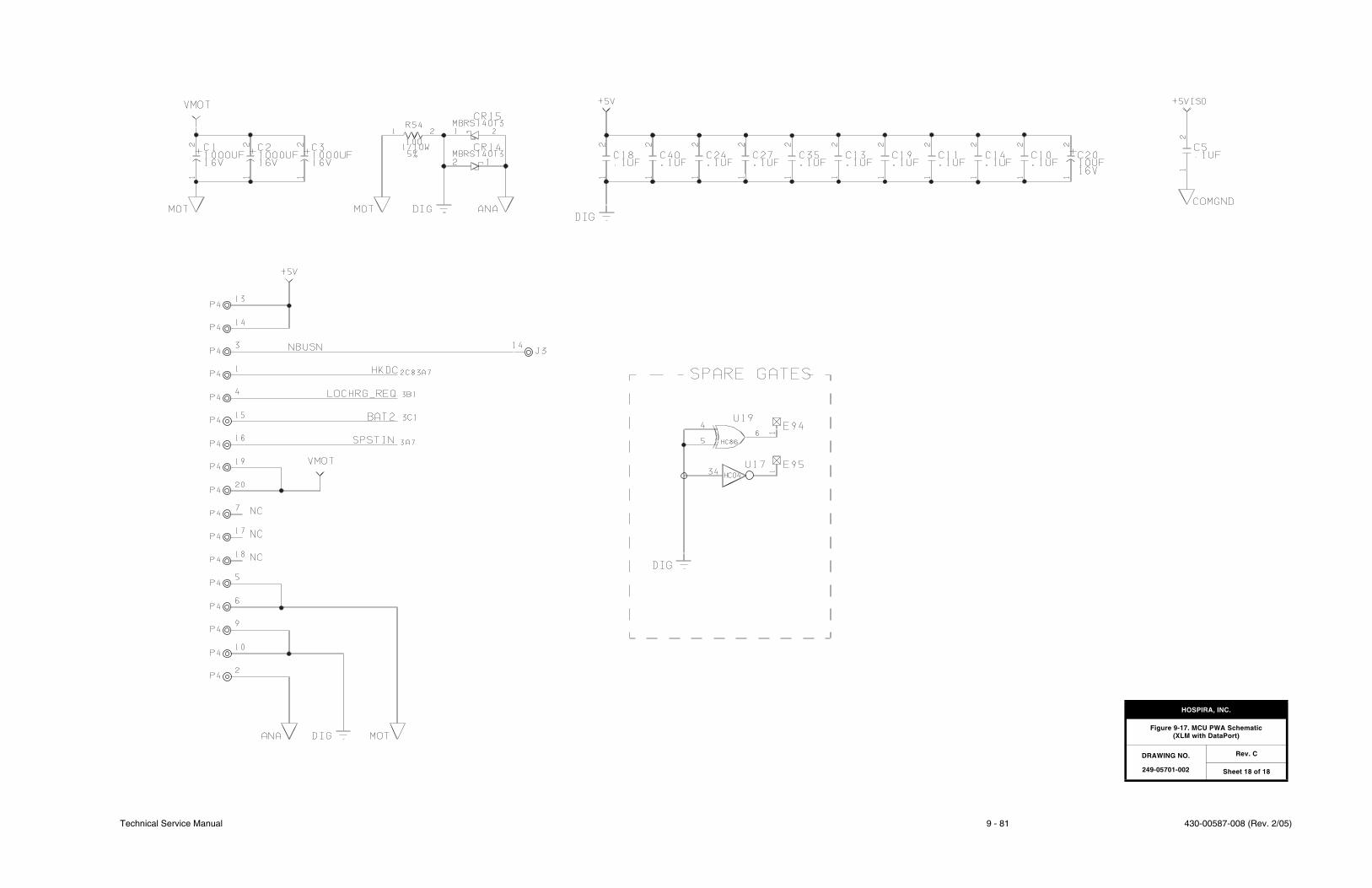
Technical Service Manual 9 - 81 430-00587-008 (Rev. 2/05)
HOSPIRA, INC.
Figure 9-17. MCU PWA Schematic(XLM with DataPort)
DRAWING NO.
249-05701-002
Rev. C
Sheet 18 of 18

430-00587-008 (Rev. 2/05) 9 - 82 Plum XL Series
SECTION 9 DRAWINGS
This page intentionally left blank.
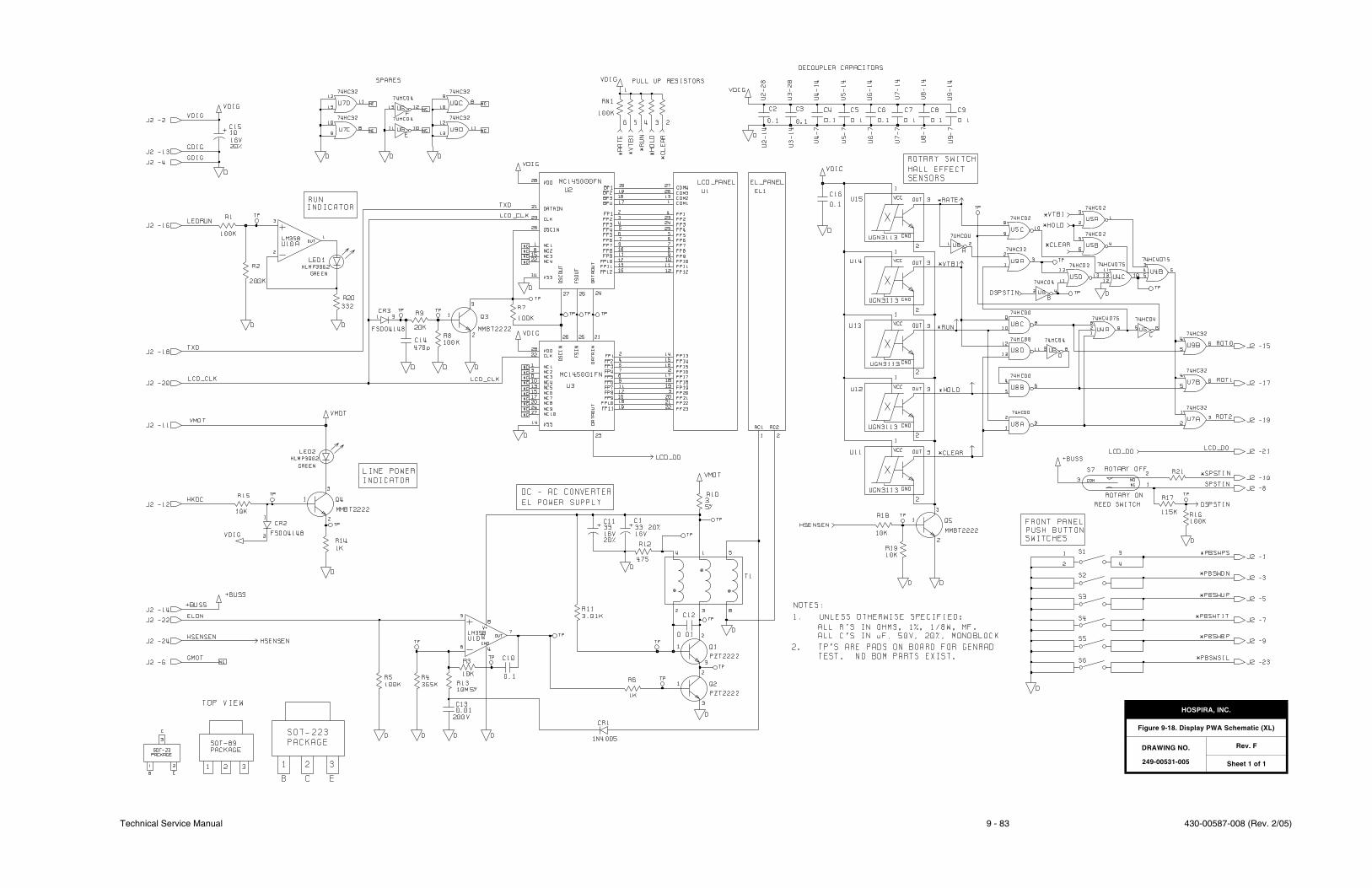
Technical Service Manual 9 - 83 430-00587-008 (Rev. 2/05)
HOSPIRA, INC.
Figure 9-18. Display PWA Schematic (XL)
DRAWING NO.
249-00531-005
Rev. F
Sheet 1 of 1

430-00587-008 (Rev. 2/05) 9 - 84 Plum XL Series
SECTION 9 DRAWINGS
This page intentionally left blank.
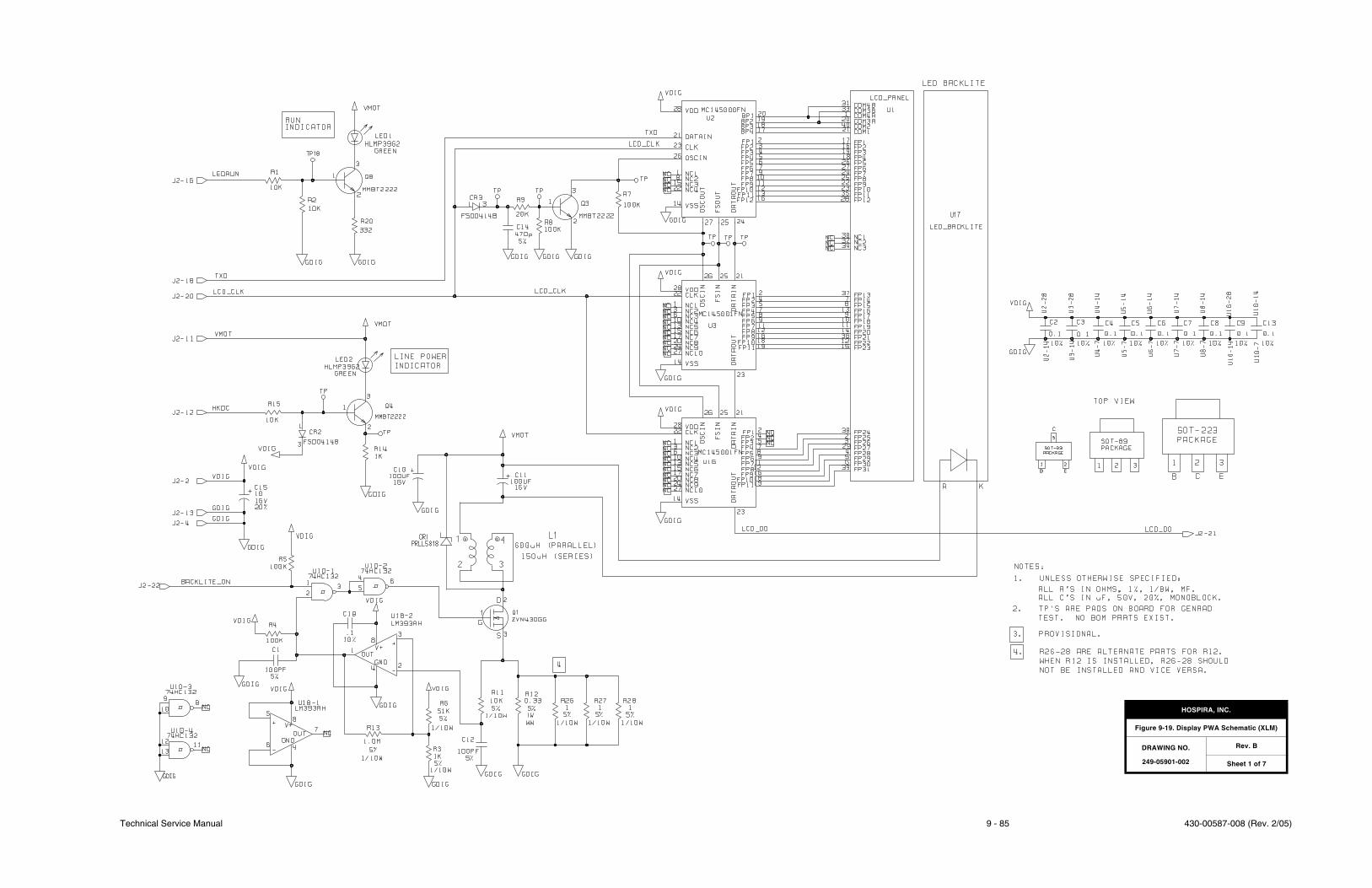
Technical Service Manual 9 - 85 430-00587-008 (Rev. 2/05)
HOSPIRA, INC.
Figure 9-19. Display PWA Schematic (XLM)
DRAWING NO.
249-05901-002
Rev. B
Sheet 1 of 7

430-00587-008 (Rev. 2/05) 9 - 86 Plum XL Series
SECTION 9 DRAWINGS
This page intentionally left blank.
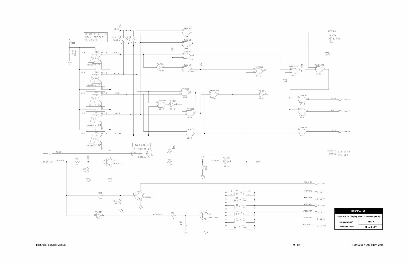
Technical Service Manual 9 - 87 430-00587-008 (Rev. 2/05)
HOSPIRA, INC.
Figure 9-19. Display PWA Schematic (XLM)
DRAWING NO.
249-05901-002
Rev. B
Sheet 2 of 7

430-00587-008 (Rev. 2/05) 9 - 88 Plum XL Series
SECTION 9 DRAWINGS
This page intentionally left blank.
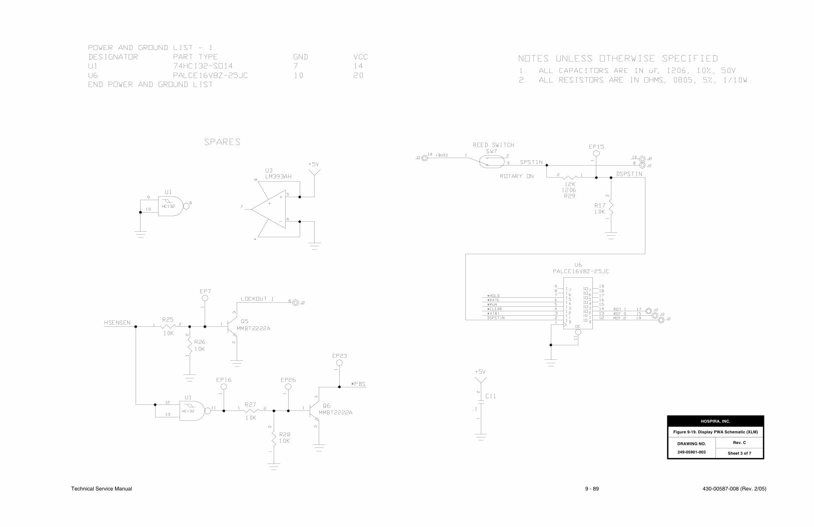
Technical Service Manual 9 - 89 430-00587-008 (Rev. 2/05)
HOSPIRA, INC.
Figure 9-19. Display PWA Schematic (XLM)
DRAWING NO.
249-05901-003
Rev. C
Sheet 3 of 7

430-00587-008 (Rev. 2/05) 9 - 90 Plum XL Series
SECTION 9 DRAWINGS
This page intentionally left blank.
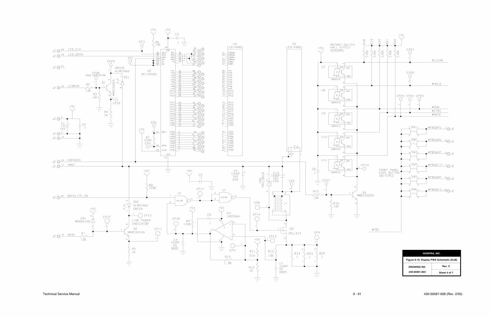
Technical Service Manual 9 - 91 430-00587-008 (Rev. 2/05)
HOSPIRA, INC.
Figure 9-19. Display PWA Schematic (XLM)
DRAWING NO.
249-05901-003
Rev. C
Sheet 4 of 7

430-00587-008 (Rev. 2/05) 9 - 92 Plum XL Series
SECTION 9 DRAWINGS
This page intentionally left blank.
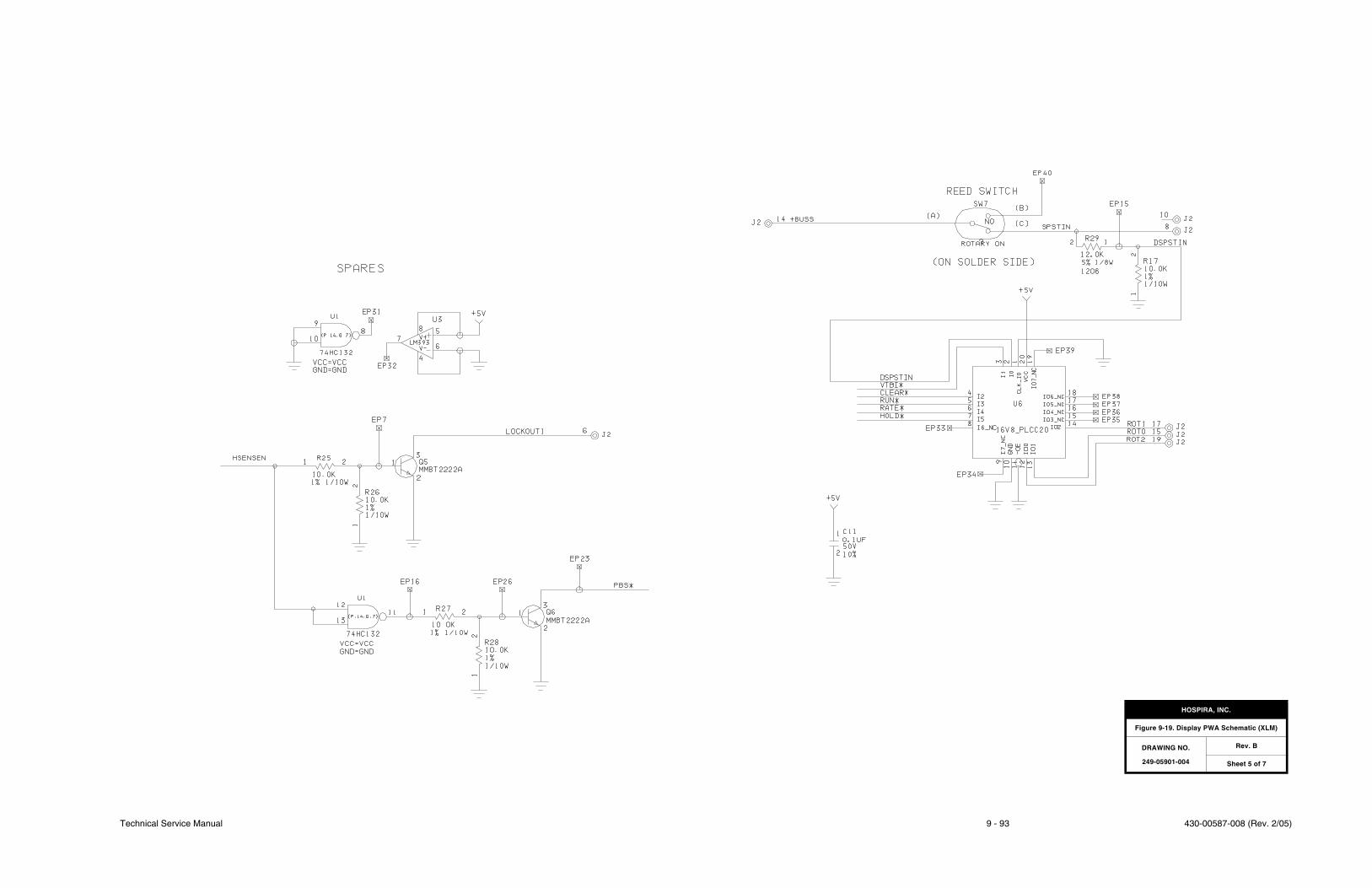
Technical Service Manual 9 - 93 430-00587-008 (Rev. 2/05)
HOSPIRA, INC.
Figure 9-19. Display PWA Schematic (XLM)
DRAWING NO.
249-05901-004
Rev. B
Sheet 5 of 7

430-00587-008 (Rev. 2/05) 9 - 94 Plum XL Series
SECTION 9 DRAWINGS
This page intentionally left blank.
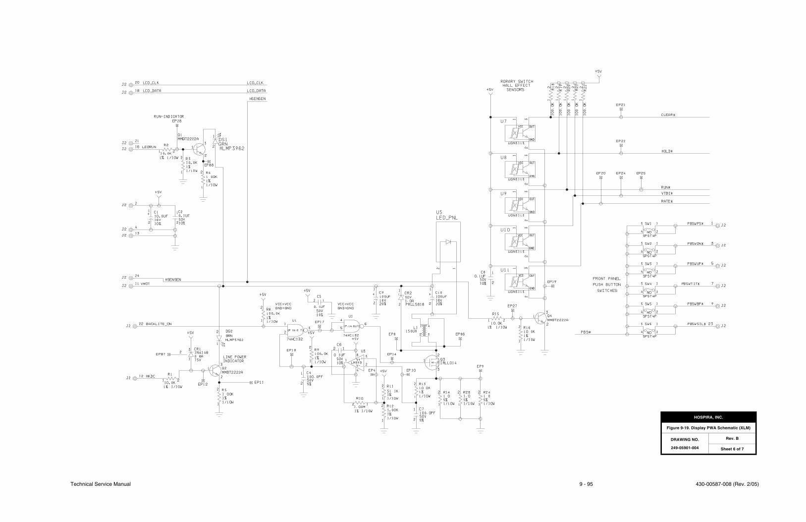
Technical Service Manual 9 - 95 430-00587-008 (Rev. 2/05)
HOSPIRA, INC.
Figure 9-19. Display PWA Schematic (XLM)
DRAWING NO.
249-05901-004
Rev. B
Sheet 6 of 7

430-00587-008 (Rev. 2/05) 9 - 96 Plum XL Series
SECTION 9 DRAWINGS
This page intentionally left blank.

Technical Service Manual 9 - 97 430-00587-008 (Rev. 2/05)
HOSPIRA, INC.
Figure 9-19. Display PWA Schematic (XLM)
DRAWING NO.
249-05901-004
Rev. B
Sheet 7 of 7

430-00587-008 (Rev. 2/05) 9 - 98 Plum XL Series
SECTION 9 DRAWINGS
This page intentionally left blank.
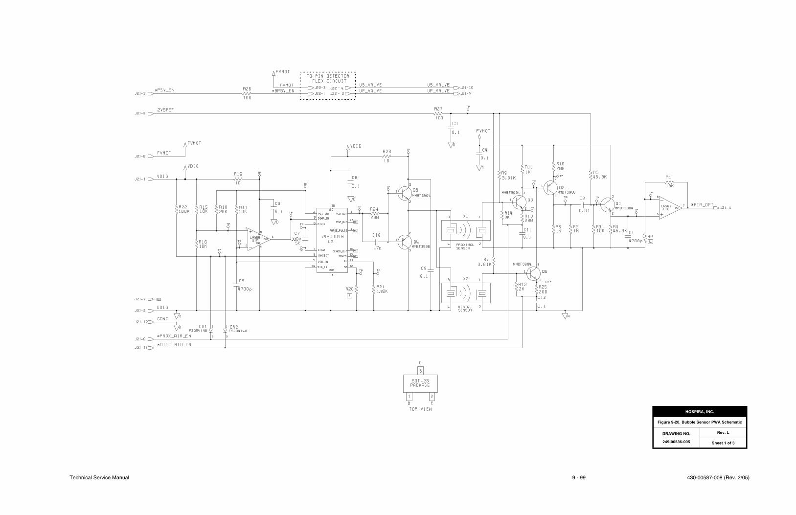
Technical Service Manual 9 - 99 430-00587-008 (Rev. 2/05)
HOSPIRA, INC.
Figure 9-20. Bubble Sensor PWA Schematic
DRAWING NO.
249-00536-005
Rev. L
Sheet 1 of 3

430-00587-008 (Rev. 2/05) 9 - 100 Plum XL Series
SECTION 9 DRAWINGS
This page intentionally left blank.
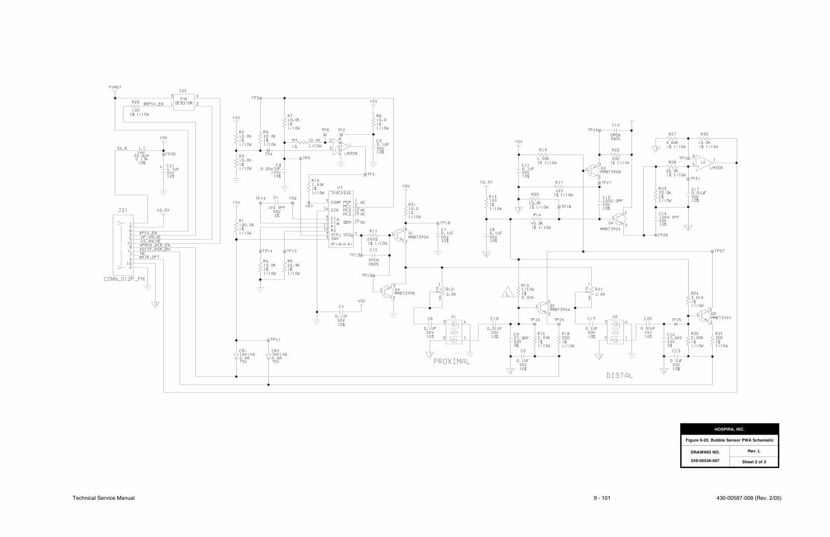
Technical Service Manual 9 - 101 430-00587-008 (Rev. 2/05)
HOSPIRA, INC.
Figure 9-20. Bubble Sensor PWA Schematic
DRAWING NO.
249-00536-007
Rev. L
Sheet 2 of 3

430-00587-008 (Rev. 2/05) 9 - 102 Plum XL Series
SECTION 9 DRAWINGS
This page intentionally left blank.
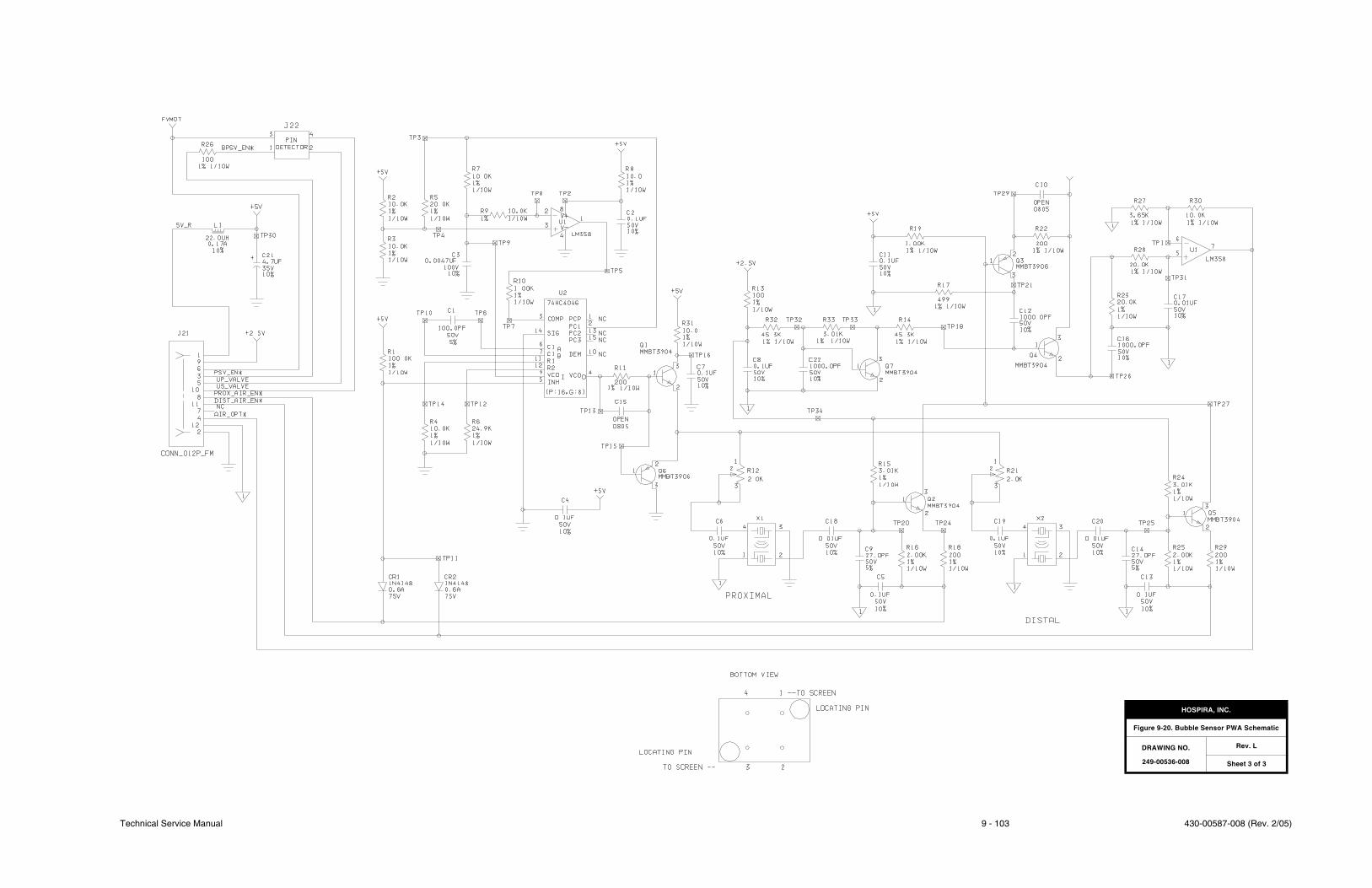
Technical Service Manual 9 - 103 430-00587-008 (Rev. 2/05)
HOSPIRA, INC.
Figure 9-20. Bubble Sensor PWA Schematic
DRAWING NO.
249-00536-008
Rev. L
Sheet 3 of 3

430-00587-008 (Rev. 2/05) 9 - 104 Plum XL Series
SECTION 9 DRAWINGS
This page intentionally left blank.
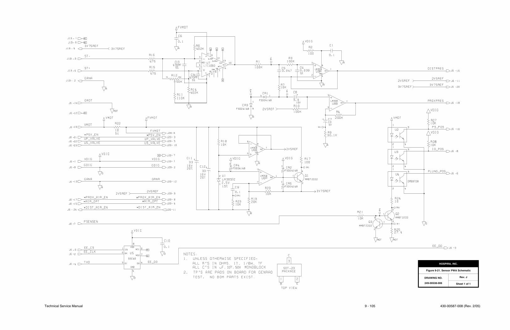
Technical Service Manual 9 - 105 430-00587-008 (Rev. 2/05)
HOSPIRA, INC.
Figure 9-21. Sensor PWA Schematic
DRAWING NO.
249-00538-006
Rev. J
Sheet 1 of 1

430-00587-008 (Rev. 2/05) 9 - 106 Plum XL Series
SECTION 9 DRAWINGS
This page intentionally left blank.
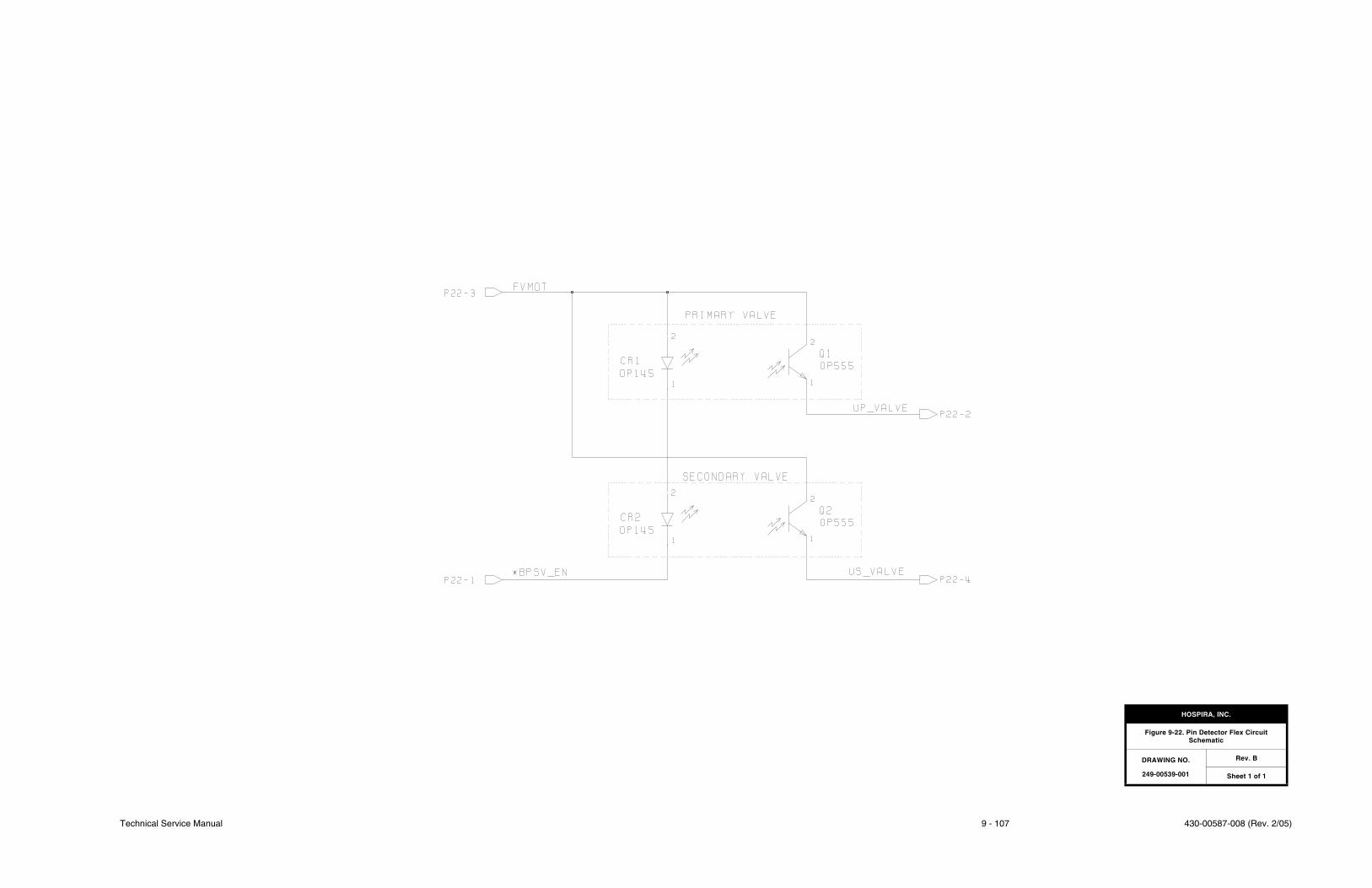
Technical Service Manual 9 - 107 430-00587-008 (Rev. 2/05)
HOSPIRA, INC.
Figure 9-22. Pin Detector Flex Circuit Schematic
DRAWING NO.
249-00539-001
Rev. B
Sheet 1 of 1

430-00587-008 (Rev. 2/05) 9 - 108 Plum XL Series
SECTION 9 DRAWINGS
This page intentionally left blank.
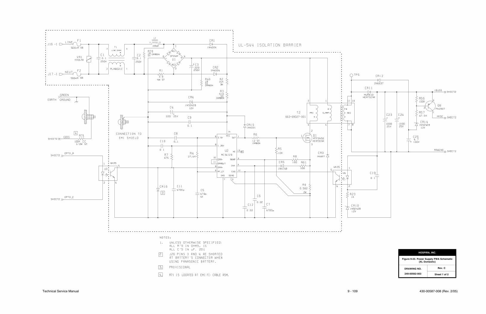
Technical Service Manual 9 - 109 430-00587-008 (Rev. 2/05)
HOSPIRA, INC.
Figure 9-23. Power Supply PWA Schematic (XL Domestic)
DRAWING NO.
249-00562-003
Rev. C
Sheet 1 of 2

430-00587-008 (Rev. 2/05) 9 - 110 Plum XL Series
SECTION 9 DRAWINGS
This page intentionally left blank.

Technical Service Manual 9 - 111 430-00587-008 (Rev. 2/05)
HOSPIRA, INC.
Figure 9-23. Power Supply PWA Schematic(XL - Domestic)
DRAWING NO.
249-00562-003
Rev. C
Sheet 2 of 2

430-00587-008 (Rev. 2/05) 9 - 112 Plum XL Series
SECTION 9 DRAWINGS
This page intentionally left blank.

Technical Service Manual 9 - 113 430-00587-008 (Rev. 2/05)
HOSPIRA, INC.
Figure 9-24. Power Supply PWA Schematic (XL International)
DRAWING NO.
249-00573-004
Rev. G
Sheet 1 of 2

430-00587-008 (Rev. 2/05) 9 - 114 Plum XL Series
SECTION 9 DRAWINGS
This page intentionally left blank.
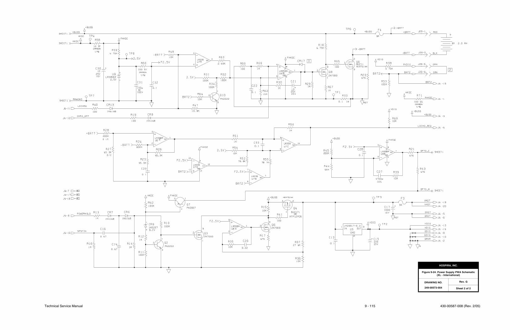
Technical Service Manual 9 - 115 430-00587-008 (Rev. 2/05)
HOSPIRA, INC.
Figure 9-24. Power Supply PWA Schematic(XL - International)
DRAWING NO.
249-00573-004
Rev. G
Sheet 2 of 2

430-00587-008 (Rev. 2/05) 9 - 116 Plum XL Series
SECTION 9 DRAWINGS
This page intentionally left blank.
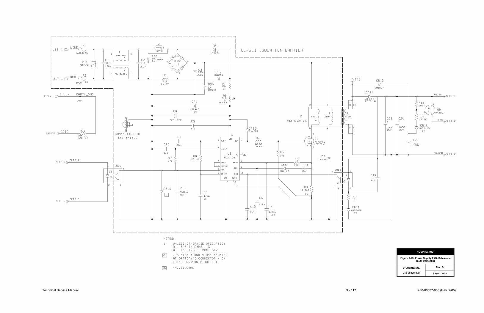
Technical Service Manual 9 - 117 430-00587-008 (Rev. 2/05)
HOSPIRA, INC.
Figure 9-25. Power Supply PWA Schematic (XLM Domestic)
DRAWING NO.
249-05920-002
Rev. B
Sheet 1 of 2

430-00587-008 (Rev. 2/05) 9 - 118 Plum XL Series
SECTION 9 DRAWINGS
This page intentionally left blank.

Technical Service Manual 9 - 119 430-00587-008 (Rev. 2/05)
HOSPIRA, INC.
Figure 9-25. Power Supply PWA Schematic(XLM - Domestic)
DRAWING NO.
249-05920-002
Rev. B
Sheet 2 of 2

430-00587-008 (Rev. 2/05) 9 - 120 Plum XL Series
SECTION 9 DRAWINGS
This page intentionally left blank.
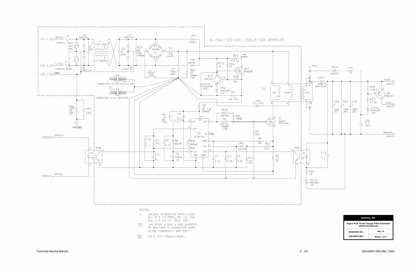
Technical Service Manual 9 - 121 430-00587-008 (Rev. 2/05)
-
ΩZ
HOSPIRA, INC.
Figure 9-26. Power Supply PWA Schematic (XLM International)
DRAWING NO.
249-05916-003
Rev. H
Sheet 1 of 4

430-00587-008 (Rev. 2/05) 9 - 122 Plum XL Series
SECTION 9 DRAWINGS
This page intentionally left blank.

Technical Service Manual 9 - 123 430-00587-008 (Rev. 2/05)
HOSPIRA, INC.
Figure 9-26. Power Supply PWA Schematic(XLM - International)
DRAWING NO.
249-05916-003
Rev. H
Sheet 2 of 4

430-00587-008 (Rev. 2/05) 9 - 124 Plum XL Series
SECTION 9 DRAWINGS
This page intentionally left blank.
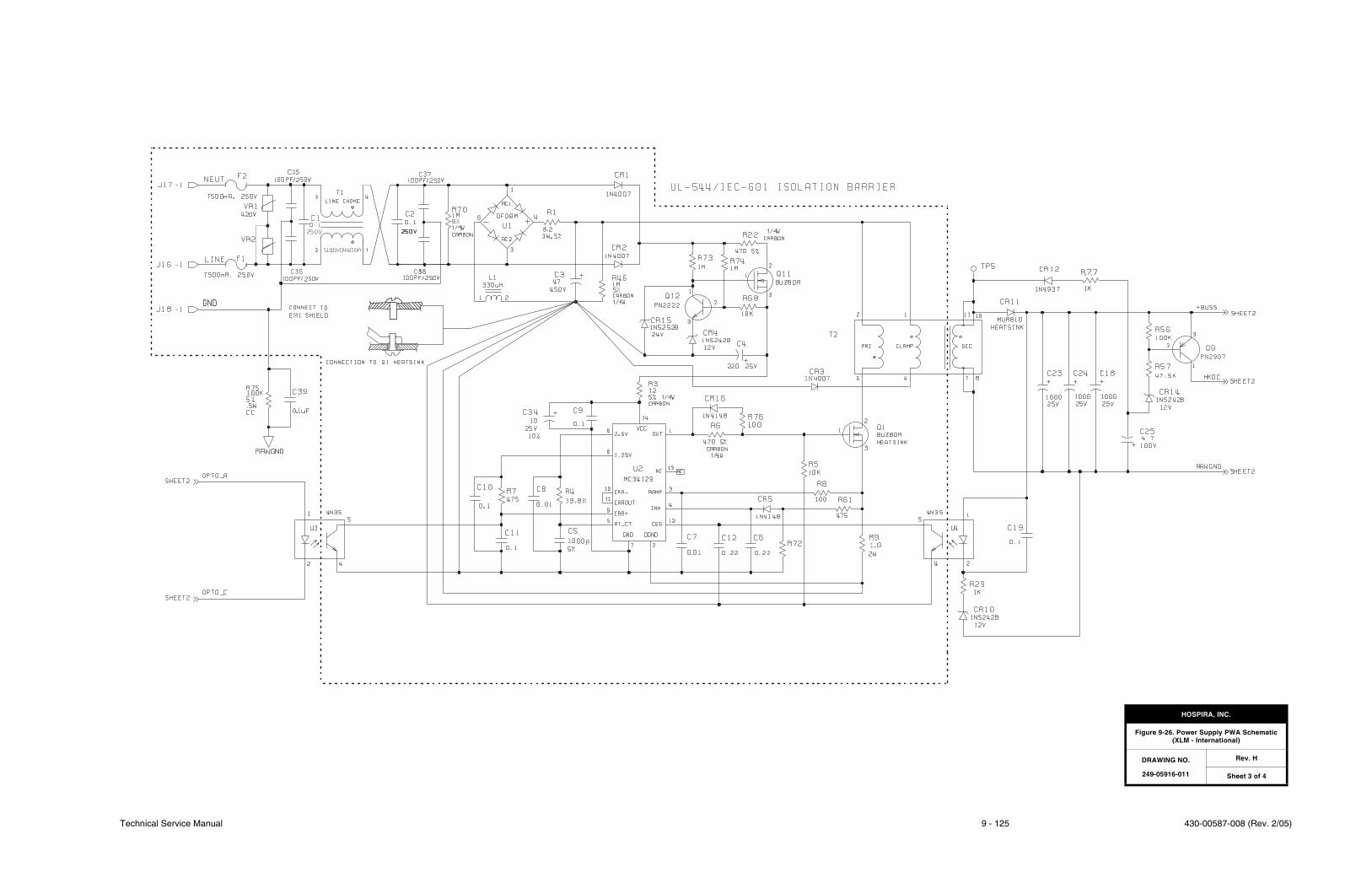
Technical Service Manual 9 - 125 430-00587-008 (Rev. 2/05)
HOSPIRA, INC.
Figure 9-26. Power Supply PWA Schematic(XLM - International)
DRAWING NO.
249-05916-011
Rev. H
Sheet 3 of 4

430-00587-008 (Rev. 2/05) 9 - 126 Plum XL Series
SECTION 9 DRAWINGS
This page intentionally left blank.

Technical Service Manual 9 - 127 430-00587-008 (Rev. 2/05)
HOSPIRA, INC.
Figure 9-26. Power Supply PWA Schematic(XLM - International)
DRAWING NO.
249-05916-011
Rev. H
Sheet 4 of 4

430-00587-008 (Rev. 2/05) 9 - 128 Plum XL Series
SECTION 9 DRAWINGS
This page intentionally left blank.

Technical Service Manual 9 - 129 430-00587-008 (Rev. 2/05)
150V
3.9
4
220250
1N4937
MTP3N50
0.562
4700p
470p
33.2K
HOSPIRA, INC.
Figure 9-27. Power Supply PWA Schematic (XLM with DataPort)
DRAWING NO.
249-05916-006
Rev. F
Sheet 1 of 4

430-00587-008 (Rev. 2/05) 9 - 130 Plum XL Series
SECTION 9 DRAWINGS
This page intentionally left blank.

Technical Service Manual 9 - 131 430-00587-008 (Rev. 2/05)
LM2940CT
HOSPIRA, INC.
Figure 9-27. Power Supply PWA Schematic(XLM with DataPort)
DRAWING NO.
249-05916-006
Rev. F
Sheet 2 of 4

430-00587-008 (Rev. 2/05) 9 - 132 Plum XL Series
SECTION 9 DRAWINGS
This page intentionally left blank.
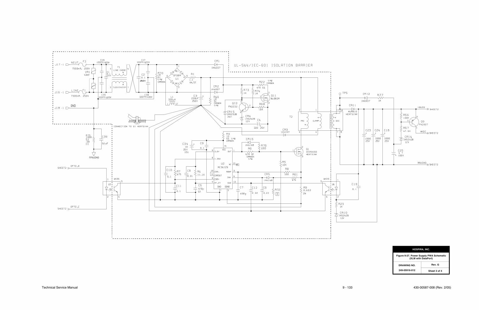
Technical Service Manual 9 - 133 430-00587-008 (Rev. 2/05)
4
9
9
HOSPIRA, INC.
Figure 9-27. Power Supply PWA Schematic(XLM with DataPort)
DRAWING NO.
249-05916-012
Rev. G
Sheet 3 of 4

430-00587-008 (Rev. 2/05) 9 - 134 Plum XL Series
SECTION 9 DRAWINGS
This page intentionally left blank.
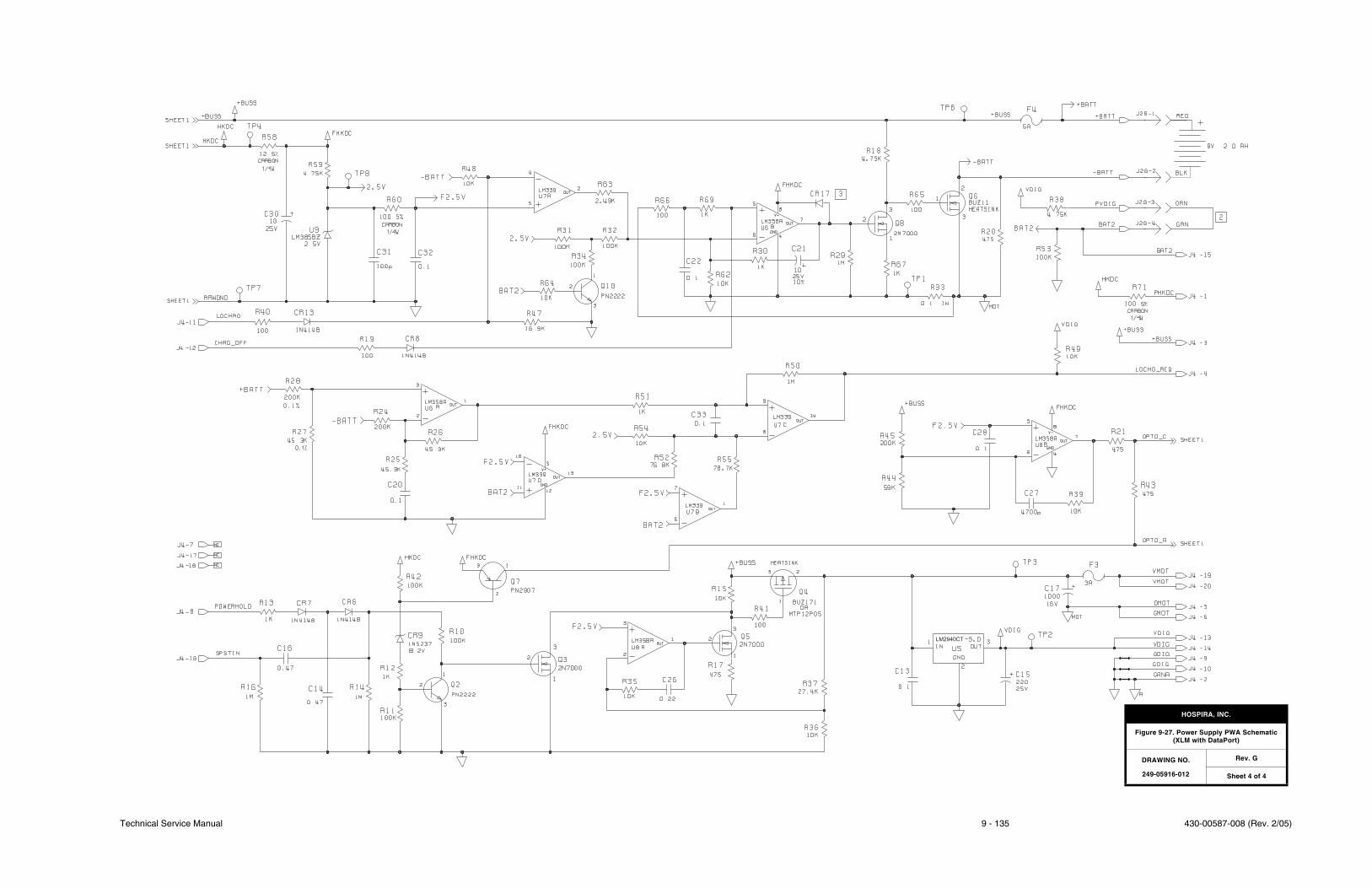
Technical Service Manual 9 - 135 430-00587-008 (Rev. 2/05)
LM2940CT
HOSPIRA, INC.
Figure 9-27. Power Supply PWA Schematic(XLM with DataPort)
DRAWING NO.
249-05916-012
Rev. G
Sheet 4 of 4

430-00587-008 (Rev. 2/05) 9 - 136 Plum XL Series
SECTION 9 DRAWINGS
This page intentionally left blank.
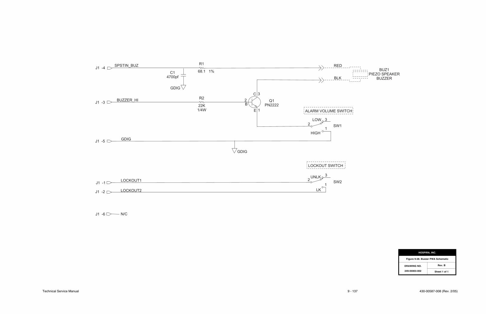
Technical Service Manual 9 - 137 430-00587-008 (Rev. 2/05)
J1 -4
J1 -3
SPSTIN_BUZ
BUZZER_HI
C1
4700pf
GDIG
J1 -5GDIG
J1 -1LOCKOUT1
J1 -2 LOCKOUT2
J1 -6 N/C
68.1 1%
R2
22K
1/4W
2
B
E 1
C 3
Q1
PN2222
ALARM VOLUME SWITCH
LOW 3
SW1
HIGH
1
2
BLK
BUZ1
PIEZO SPEAKER
BUZZER
RED
LOCKOUT SWITCH
3
2UNLK
SW2
LK
1
GDIG
R1
HOSPIRA, INC.
Figure 9-28. Buzzer PWA Schematic
DRAWING NO.
249-05903-002
Rev. B
Sheet 1 of 1

430-00587-008 (Rev. 2/05) 9 - 138 Plum XL Series
SECTION 9 DRAWINGS
This page intentionally left blank.

Technical Service Manual A - 1 430-00587-008 (Rev. 1/05)
APPENDIX
CONSIDERATIONS FOR USE INELECTROMAGNETIC ENVIRONMENTS
The LifeCare XLM with DataPort (outside of the United States) is intended for usein the electromagnetic environment specified in Electromagnetic Emissions,Electromagnetic Immunity, and Electromagnetic Immunity for Life-Supporting Equipmentand Systems. The user of the device should assure that it is used only in the appropriateenvironment.
Note: Do not connect DataPort when infusing.
ELECTROMAGNETIC EMISSIONS
Table A-1, Guidance and Manufacturer’s Declaration - Electromagnetic Emissions detailselectromagnetic emissions compliance and guidance for XLM Series infusion systems
Table A-1. Guidance and Manufacturer’s Declaration - Electromagnetic Emissions
Emissions Test Compliance Electromagnetic Enforcement - Guidance
RF Emissions CISPR 11
Group 1 The LifeCare XLM with DataPort uses RF energy only for its internal function. Therefore, its RF emissions are very low and are not likely to cause interference in nearby electronic equipment.
RF Emissions CISPR 11
Class B The LifeCare XLM with DataPort is suitable for use in all establishments, including domestic establishments and those directly connected to the public low voltage power supply network that supplies buildings used for domestic purposes.
Harmonic emissions IEC 61000-3-2
Class B
Voltage fluctuations/flicker emissions IEC 61000-3-3
Complies
EN-2
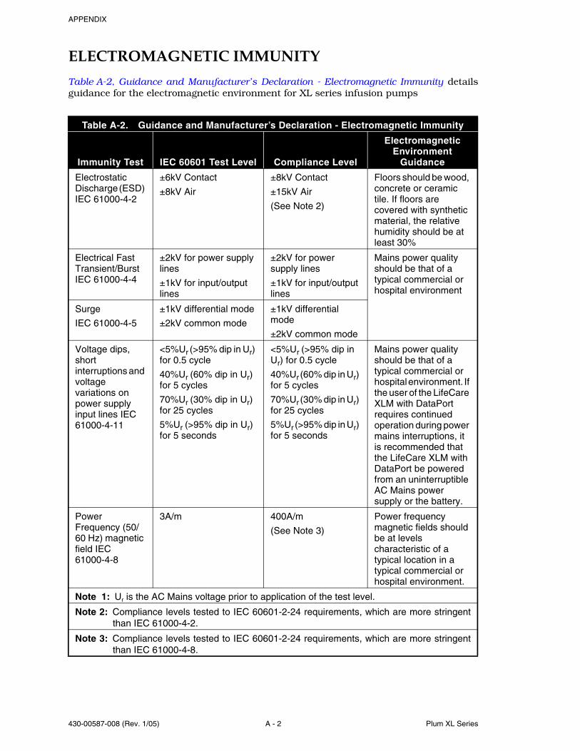
APPENDIX
430-00587-008 (Rev. 1/05) A - 2 Plum XL Series
ELECTROMAGNETIC IMMUNITY
Table A-2, Guidance and Manufacturer’s Declaration - Electromagnetic Immunity detailsguidance for the electromagnetic environment for XL series infusion pumps
Table A-2. Guidance and Manufacturer’s Declaration - Electromagnetic Immunity
Immunity Test IEC 60601 Test Level Compliance Level
Electromagnetic Environment
Guidance
Electrostatic Discharge (ESD) IEC 61000-4-2
±6kV Contact
±8kV Air
±8kV Contact
±15kV Air
(See Note 2)
Floors should be wood, concrete or ceramic tile. If floors are covered with synthetic material, the relative humidity should be at least 30%
Electrical Fast Transient/Burst IEC 61000-4-4
±2kV for power supply lines
±1kV for input/output lines
±2kV for power supply lines
±1kV for input/output lines
Mains power quality should be that of a typical commercial or hospital environment
Surge
IEC 61000-4-5
±1kV differential mode
±2kV common mode
±1kV differential mode
±2kV common mode
Voltage dips, short interruptions and voltage variations on power supply input lines IEC 61000-4-11
<5%Ur (>95% dip in Ur) for 0.5 cycle
40%Ur (60% dip in Ur) for 5 cycles
70%Ur (30% dip in Ur) for 25 cycles
5%Ur (>95% dip in Ur) for 5 seconds
<5%Ur (>95% dip in Ur) for 0.5 cycle
40%Ur (60% dip in Ur) for 5 cycles
70%Ur (30% dip in Ur) for 25 cycles
5%Ur (>95% dip in Ur) for 5 seconds
Mains power quality should be that of a typical commercial or hospital environment. If the user of the LifeCare XLM with DataPort requires continued operation during power mains interruptions, it is recommended that the LifeCare XLM with DataPort be powered from an uninterruptible AC Mains power supply or the battery.
Power Frequency (50/60 Hz) magnetic field IEC 61000-4-8
3A/m 400A/m
(See Note 3)
Power frequency magnetic fields should be at levels characteristic of a typical location in a typical commercial or hospital environment.
Note 1: Ur is the AC Mains voltage prior to application of the test level.
Note 2: Compliance levels tested to IEC 60601-2-24 requirements, which are more stringentthan IEC 61000-4-2.
Note 3: Compliance levels tested to IEC 60601-2-24 requirements, which are more stringentthan IEC 61000-4-8.
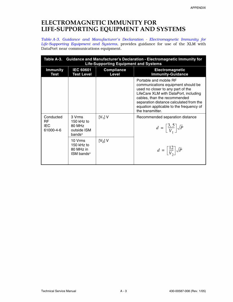
APPENDIX
Technical Service Manual A - 3 430-00587-008 (Rev. 1/05)
ELECTROMAGNETIC IMMUNITY FOR LIFE-SUPPORTING EQUIPMENT AND SYSTEMS
Table A-3, Guidance and Manufacturer’s Declaration - Electromagnetic Immunity forLife-Supporting Equipment and Systems, provides guidance for use of the XLM withDataPort near communications equipment.
Table A-3. Guidance and Manufacturer’s Declaration - Electromagnetic Immunity for Life-Supporting Equipment and Systems
Immunity Test
IEC 60601 Test Level
Compliance Level
Electromagnetic Immunity-Guidance
Portable and mobile RF communications equipment should be used no closer to any part of the LifeCare XLM with DataPort, including cables, than the recommended separation distance calculated from the equation applicable to the frequency of the transmitter.
Conducted RF IEC 61000-4-6
3 Vrms150 kHz to 80 MHz outside ISM bandsa
[V1] V Recommended separation distance
10 Vrms150 kHz to 80 MHz in ISM bandsa
[V2] V
d3 5,V1--------- P=
d12V2------ P=
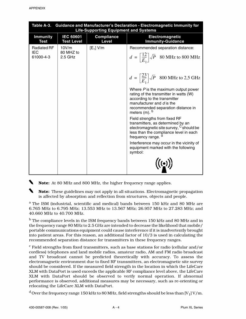
APPENDIX
430-00587-008 (Rev. 1/05) A - 4 Plum XL Series
Note: At 80 MHz and 800 MHz, the higher frequency range applies.
Note: These guidelines may not apply in all situations. Electromagnetic propagationis affected by absorption and reflection from structures, objects and people.
a The ISM (industrial, scientific and medical) bands between 150 kHz and 80 MHz are6.765 MHz to 6.795 MHz; 13.553 MHz to 13.567 MHz; 26.957 MHz to 27.283 MHz; and40.660 MHz to 40.700 MHz.b The compliance levels in the ISM frequency bands between 150 kHz and 80 MHz and inthe frequency range 80 MHz to 2.5 GHz are intended to decrease the likelihood that mobile/portable communications equipment could cause interference if it is inadvertently broughtinto patient areas. For this reason, an additional factor of 10/3 is used in calculating therecommended separation distance for transmitters in these frequency ranges.c Field strengths from fixed transmitters, such as base stations for radio (cellular and/orcordless) telephones and land mobile radios, amateur radio, AM and FM radio broadcastand TV broadcast cannot be predicted theoretically with accuracy. To assess theelectromagnetic environment due to fixed RF transmitters, an electromagnetic site surveyshould be considered. If the measured field strength in the location in which the LifeCareXLM with DataPort is used exceeds the applicable RF compliance level above, the LifeCareXLM with DataPort should be observed to verify normal operation. If abnormalperformance is observed, additional measures may be necessary, such as re-orienting orrelocating the LifeCare XLM with DataPort.d Over the frequency range 150 kHz to 80 MHz, field strengths should be less than [V1] V/m.
Radiated RF IEC 61000-4-3
10V/m80 MHZ to 2.5 GHz
[E1] V/m Recommended separation distance:
Where P is the maximum output power rating of the transmitter in watts (W) according to the transmitter manufacturer and d is the recommended separation distance in meters (m). b
Field strengths from fixed RF transmitters, as determined by an electromagnetic site survey, C should be less than the compliance level in each frequency range. d
Interference may occur in the vicinity of equipment marked with the following symbol:
Table A-3. Guidance and Manufacturer’s Declaration - Electromagnetic Immunity for Life-Supporting Equipment and Systems
Immunity Test
IEC 60601 Test Level
Compliance Level
Electromagnetic Immunity-Guidance
d12E1------ P 80 MHz to 800 MHz=
d23E1------ P 800 MHz to 2,5 GHz=
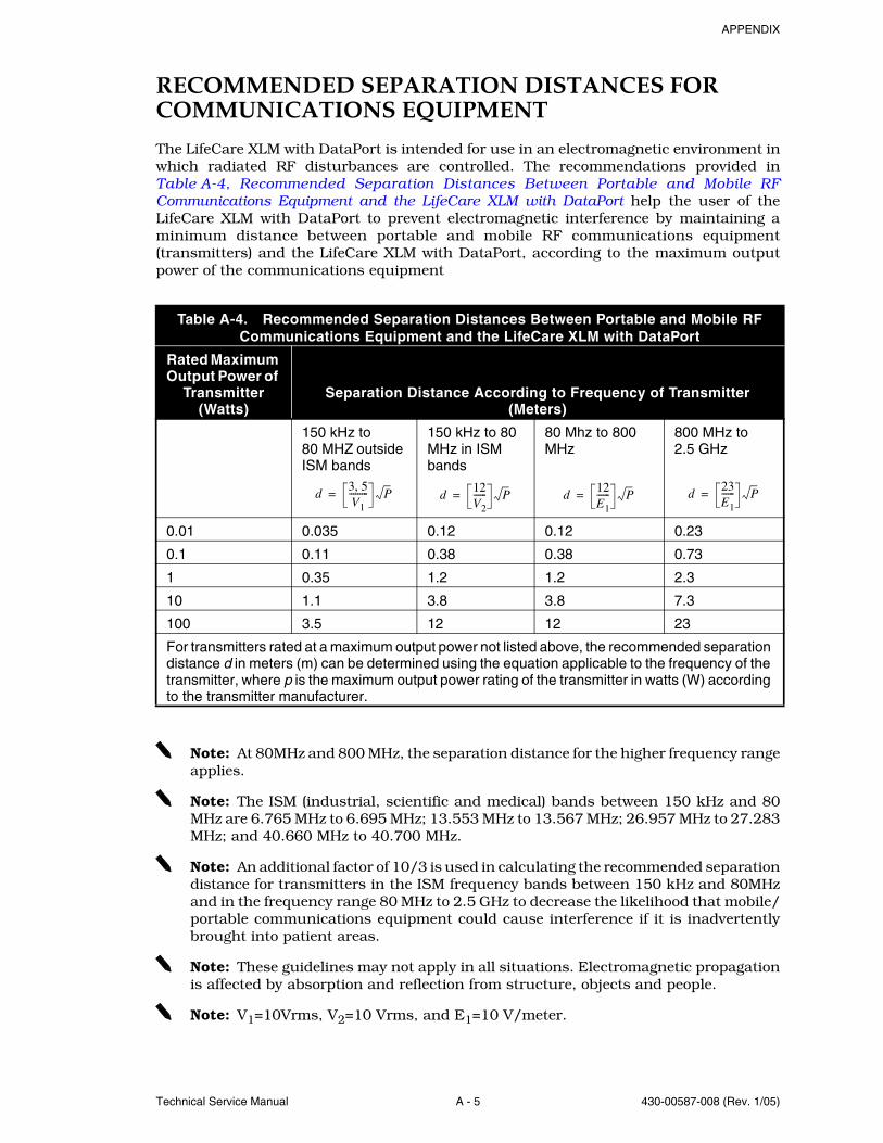
APPENDIX
Technical Service Manual A - 5 430-00587-008 (Rev. 1/05)
RECOMMENDED SEPARATION DISTANCES FOR COMMUNICATIONS EQUIPMENT
The LifeCare XLM with DataPort is intended for use in an electromagnetic environment inwhich radiated RF disturbances are controlled. The recommendations provided inTable A-4, Recommended Separation Distances Between Portable and Mobile RFCommunications Equipment and the LifeCare XLM with DataPort help the user of theLifeCare XLM with DataPort to prevent electromagnetic interference by maintaining aminimum distance between portable and mobile RF communications equipment(transmitters) and the LifeCare XLM with DataPort, according to the maximum outputpower of the communications equipment
Note: At 80MHz and 800 MHz, the separation distance for the higher frequency rangeapplies.
Note: The ISM (industrial, scientific and medical) bands between 150 kHz and 80MHz are 6.765 MHz to 6.695 MHz; 13.553 MHz to 13.567 MHz; 26.957 MHz to 27.283MHz; and 40.660 MHz to 40.700 MHz.
Note: An additional factor of 10/3 is used in calculating the recommended separationdistance for transmitters in the ISM frequency bands between 150 kHz and 80MHzand in the frequency range 80 MHz to 2.5 GHz to decrease the likelihood that mobile/portable communications equipment could cause interference if it is inadvertentlybrought into patient areas.
Note: These guidelines may not apply in all situations. Electromagnetic propagationis affected by absorption and reflection from structure, objects and people.
Note: V1=10Vrms, V2=10 Vrms, and E1=10 V/meter.
Table A-4. Recommended Separation Distances Between Portable and Mobile RF Communications Equipment and the LifeCare XLM with DataPort
Rated Maximum Output Power of
Transmitter (Watts)
Separation Distance According to Frequency of Transmitter (Meters)
150 kHz to 80 MHZ outside ISM bands
150 kHz to 80 MHz in ISM bands
80 Mhz to 800 MHz
800 MHz to 2.5 GHz
0.01 0.035 0.12 0.12 0.23
0.1 0.11 0.38 0.38 0.73
1 0.35 1.2 1.2 2.3
10 1.1 3.8 3.8 7.3
100 3.5 12 12 23
For transmitters rated at a maximum output power not listed above, the recommended separation distance d in meters (m) can be determined using the equation applicable to the frequency of the transmitter, where p is the maximum output power rating of the transmitter in watts (W) according to the transmitter manufacturer.
d3 5,V1--------- P= d
12V2------ P= d
12E1------ P= d
23E1------ P=

APPENDIX
430-00587-008 (Rev. 1/05) A - 6 Plum XL Series
This page intentionally left blank.
Technical Service Manual I - 1 430-00587-008 (Rev. 2/05)
INDEX
A
AC amplifier circuitry, 4-14AC power cord replacement
(115V), 7-19(220V), 7-21
AC receptacle replacement (220V), 7-22Acronyms and abbreviations, 1-6Adhesive-backed insulator
replacement, 7-28Alarm circuitry
XL, 4-8XLM, 4-8
Alarm history, 6-11Alarm loudness and lock function tests
(XLM), 5-9Alarm loudness test (XL), 5-9Alarm messages and error codes, 6-1
Error codes requiring technical service, 6-6
Operational alarm messages, 6-2Service mode, 6-11
Alarm power backup circuitry, 4-8Artifacts, 1-8
B
BatteryCharger circuitry
115 volt, 4-4220 volt, 4-6
Charger current test, 5-15Door pad replacement, 7-6Door replacement, 7-6Legend test, 5-10Operation overview, 5-14Replacement, 7-6Run time, 6-12
Bubble sensor PWA, 4-14Pin detector flex circuitry, 4-15Receiver circuitry, 4-15Schematic, 9-99Transmitter circuitry, 4-15
Buzzer PWA, 4-10Lockout switch, 4-11Replacement, 7-31Schematic, 9-137
C
Cassette, 4-16Door replacement, 7-36
Channel label, 6-13Cleaning, 5-1
Solutions, 5-2Communication selection, 6-13Component designators, 1-6Considerations for use in electromagnetic
environments, A-1Electromagnetic emissions, A-1Electromagnetic immunity for
life-supporting equipment and systems, A-3
Electromagnetic immunity, A-2Recommended separation distances
for communications equipment, A-5Control knob
Circuitry (XL), 4-13Circuitry (XLM), 4-13Replacement, 7-13
Conventions, 1-5
D
DataPort connection and ground continuity test, 5-16
DataPort/MCU cable replacement, 7-25Delivery accuracy test, 5-12Detent ring replacement, 7-13Display circuitry
XL, 4-11XLM display PWA -003 and lower, 4-11XLM display PWA -004 and
higher, 4-11Display PWA, 4-11
Control knob circuitry, 4-13Display circuitry (XL), 4-11Display circuitry (XLM display PWA
-003 and lower), 4-11Display circuitry (XLM display PWA
-004 and higher), 4-11EL panel driver circuitry, 4-12LED backlight panel and driver, 4-12Line power indicator circuitry, 4-12Replacement, 7-11
INDEX
430-00587-008 (Rev. 2/05) I - 2 Plum XL Series
Run indicator circuitry, 4-12Schematic
XL, 9-83XLM, 9-85
Distal occlusion test, 5-11Drawings, 9-1
E
EEPROM circuitry, 4-14Electrical safety test, 5-13Electroluminescent panel driver circuitry
(XL), 4-12Electromagnetic
Emissions, A-1Immunity for life-supporting
equipment and systems, A-3Immunity, A-2
Electronics overview, 4-2Bubble sensor PWA, 4-14Buzzer PWA, 4-10Display PWA, 4-11MCU PWA, 4-7Power supply PWA, 4-2, 4-5Sensor PWA, 4-13
EMI shield replacement, 7-22Empty container/air-in-line alarm
test, 5-12End of performance verification test, 5-14Equipment required, 5-4Equipotential post
replacement, 7-22, 7-23Error codes requiring technical
service, 6-6
F
Free flow test, 5-10Front enclosure assembly
Component replacement, 7-10Display PWA, 7-11Front panel key replacement, 7-12MCU/display cable, 7-11
Replacement, 7-9Front panel
Key replacement, 7-12Label replacement, 7-14
Fuse replacement, 7-15
G
General description, 4-1Global product configurations, 1-2
H
High volume audible alarm, 4-10Hospira, 6-1
I
Icons and english language equivalents, 5-5
Illustrated parts breakdown, 9-2, 9-7Inlet/outlet valve subsystem, 4-20Inspecting the infusion system, 5-1Inspection, 1-9, 5-6Instrument installation procedure, 1-8
Inspection, 1-9Self test, 1-9Unpacking, 1-8
Introduction, 1-1
K
Keypad and control knob test, 5-8Knob
Detent replacement, 7-13Gasket replacement, 7-13Washer replacement, 7-13
L
LED backlight panel and driver (XLM), 4-12
LifeCare AC receptacleBracket replacement, 7-23Gasket replacement, 7-23Housing seal replacement, 7-23Replacement, 7-23
LifeCare DataPort/MCU cable replacement, 7-27
Line power indicator circuitry, 4-12Lockout switch, 4-11
M
Main chassis assemblyComponent replacement, 7-32Replacement, 7-9
Maintenance and service tests, 5-1Battery operation overview, 5-14DataPort connection and ground
continuity test, 5-16Nurse call function test, 5-18
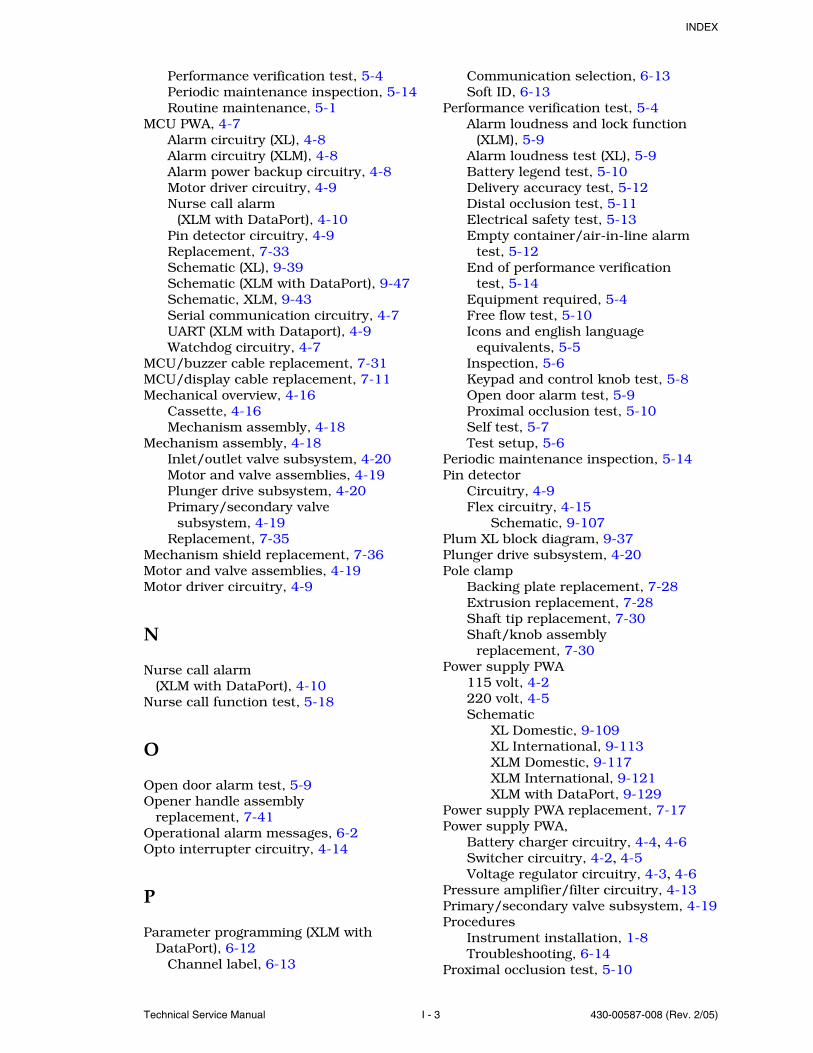
INDEX
Technical Service Manual I - 3 430-00587-008 (Rev. 2/05)
Performance verification test, 5-4Periodic maintenance inspection, 5-14Routine maintenance, 5-1
MCU PWA, 4-7Alarm circuitry (XL), 4-8Alarm circuitry (XLM), 4-8Alarm power backup circuitry, 4-8Motor driver circuitry, 4-9Nurse call alarm
(XLM with DataPort), 4-10Pin detector circuitry, 4-9Replacement, 7-33Schematic (XL), 9-39Schematic (XLM with DataPort), 9-47Schematic, XLM, 9-43Serial communication circuitry, 4-7UART (XLM with Dataport), 4-9Watchdog circuitry, 4-7
MCU/buzzer cable replacement, 7-31MCU/display cable replacement, 7-11Mechanical overview, 4-16
Cassette, 4-16Mechanism assembly, 4-18
Mechanism assembly, 4-18Inlet/outlet valve subsystem, 4-20Motor and valve assemblies, 4-19Plunger drive subsystem, 4-20Primary/secondary valve
subsystem, 4-19Replacement, 7-35
Mechanism shield replacement, 7-36Motor and valve assemblies, 4-19Motor driver circuitry, 4-9
N
Nurse call alarm (XLM with DataPort), 4-10
Nurse call function test, 5-18
O
Open door alarm test, 5-9Opener handle assembly
replacement, 7-41Operational alarm messages, 6-2Opto interrupter circuitry, 4-14
P
Parameter programming (XLM with DataPort), 6-12
Channel label, 6-13
Communication selection, 6-13Soft ID, 6-13
Performance verification test, 5-4Alarm loudness and lock function
(XLM), 5-9Alarm loudness test (XL), 5-9Battery legend test, 5-10Delivery accuracy test, 5-12Distal occlusion test, 5-11Electrical safety test, 5-13Empty container/air-in-line alarm
test, 5-12End of performance verification
test, 5-14Equipment required, 5-4Free flow test, 5-10Icons and english language
equivalents, 5-5Inspection, 5-6Keypad and control knob test, 5-8Open door alarm test, 5-9Proximal occlusion test, 5-10Self test, 5-7Test setup, 5-6
Periodic maintenance inspection, 5-14Pin detector
Circuitry, 4-9Flex circuitry, 4-15
Schematic, 9-107Plum XL block diagram, 9-37Plunger drive subsystem, 4-20Pole clamp
Backing plate replacement, 7-28Extrusion replacement, 7-28Shaft tip replacement, 7-30Shaft/knob assembly
replacement, 7-30Power supply PWA
115 volt, 4-2220 volt, 4-5Schematic
XL Domestic, 9-109XL International, 9-113XLM Domestic, 9-117XLM International, 9-121XLM with DataPort, 9-129
Power supply PWA replacement, 7-17Power supply PWA,
Battery charger circuitry, 4-4, 4-6Switcher circuitry, 4-2, 4-5Voltage regulator circuitry, 4-3, 4-6
Pressure amplifier/filter circuitry, 4-13Primary/secondary valve subsystem, 4-19Procedures
Instrument installation, 1-8Troubleshooting, 6-14
Proximal occlusion test, 5-10

INDEX
430-00587-008 (Rev. 2/05) I - 4 Plum XL Series
R
Rear enclosure assemblyComponent replacement, 7-14Replacement, 7-9
Receiver circuitry, 4-15Recommended separation distances for
communications equipment, A-5Replaceable parts and repairs, 7-1Replacement procedures, 7-3
AC power cord (115V), 7-19AC power cord (220 volt), 7-21AC receptacle, 7-22Battery door pad, 7-6Battery door, 7-6Battery, 7-6Buzzer PWA, 7-31Cassette door, 7-36Control knob, 7-13DataPort/MCU cable
replacement, 7-25EMI shield, 7-22Equipotential post, 7-22Front enclosure assembly
components, 7-10Front enclosure assembly, 7-9Front panel label, 7-14Fuse, 7-15LifeCare AC receptacle, 7-23LifeCare DataPort/MCU cable, 7-27Main chassis assembly
components, 7-32Main chassis assembly, 7-9MCU PWA, 7-33MCU/buzzer cable replacement, 7-31Mechanism assembly, 7-35Mechanism shield replacement, 7-36Opener handle assembly, 7-41Pole clamp components, 7-28Pole clamp shaft tip, 7-30Pole clamp shaft/knob assembly, 7-30Power supply PWA, 7-17Rear enclosure assembly
components, 7-14Rear enclosure assembly, 7-9Required tools and materials, 7-3Rubber foot pad replacement, 7-4Safety and equipment precautions, 7-3Sensor/MCU cable assembly, 7-33Separating the front, rear, and main
chassis assemblies, 7-7Strain relief bushing, 7-19Velcro retainer strap, 7-19
Required tools and materials, 7-3Routine maintenance, 5-1
Cleaning, 5-1
Inspecting the infusion system, 5-1Sanitizing the infusion system, 5-2
Rubber foot pad replacement, 7-4Run indicator circuitry, 4-12Run time, 6-12
S
Safety and equipment precautions, 7-3Sanitizing the infusion system, 5-2Schematics
Bubble sensor PWA, 9-99Buzzer PWA, 9-137Display PWA (XL), 9-83Display PWA (XLM), 9-85MCU PWA (XL), 9-39MCU PWA (XLM with DataPort), 9-47MCU PWA (XLM), 9-43Pin detector flex circuit, 9-107Plum XL block diagram, 9-37Power supply PWA
XL Domestic, 9-109XL International, 9-113XLM Domestic, 9-117XLM International, 9-121XLM with DataPort, 9-129
Scope, 1-1Self test, 1-9, 5-7Sensor PWA, 4-13
AC amplifier circuitry, 4-14EEPROM Circuitry, 4-14Opto interrupter circuitry, 4-14Pressure amplifier/filter circuitry, 4-13Voltage reference circuitry, 4-14
Sensor/MCU cable assembly replacement, 7-33
Separating the front, rear, and main chassis assemblies, 7-7
Serial communication circuitry, 4-7Service mode, 6-11
Alarm history, 6-11Battery run time, 6-12Parameter programming, 6-12Run time, 6-12Software revision number, 6-12
Snap retainer replacement, 7-13Soft ID, 6-13Software revision number, 6-12Specifications, 8-1
LifeCare XL and XLM, 8-2Plum XL and XLM, 8-1
Strain relief bushing replacement, 7-19

INDEX
Technical Service Manual I - 5 430-00587-008 (Rev. 2/05)
Switcher circuitry115 volt, 4-2220 volt, 4-5
System operating manual, 3-1
T
Technical assistance, 6-1Test setup, 5-6Tests
Alarm loudness (XL), 5-9Alarm loudness and lock function
(XLM), 5-9Battery charger current, 5-15Battery legend, 5-10DataPort connection and ground
continuity, 5-16Delivery accuracy, 5-12Distal occlusion, 5-11Electrical safety, 5-13Empty container/air-in-line
alarm, 5-12Free flow, 5-10Keypad and control knob, 5-8Nurse call function, 5-18Open door alarm, 5-9Performance verification, 5-4Proximal occlusion, 5-10Self, 1-9, 5-7
Theory of operation, 4-1Electronics overview, 4-2General description, 4-1Mechanical overview, 4-16
Transmitter circuitry, 4-15Troubleshooting, 6-1
Alarm messages and error codes, 6-1Procedures, 6-14Technical assistance, 6-1
U
Universal Asynchronous Receiver/Transmitter, 4-9
Unpacking, 1-8User qualification, 1-7
V
Velcro retainer strap, 7-19Voltage reference circuitry, 4-14Voltage regulator circuitry
115 volt, 4-3220 volt, 4-6
W
Warranty, 2-1Watchdog circuitry, 4-7

INDEX
430-00587-008 (Rev. 2/05) I - 6 Plum XL Series
This page intentionally left blank.
Technical Service Manual 430-00587-008-END (Rev. 2/05)
For technical assistance, product return authorization, and to order parts, accessories,or manuals within the United States, contact Hospira Technical Support Operations.
1-800-241-4002
For additional technical assistance, technical training, and product information, visit thewebsite at: www.hospira.com
Send all authorized, prepaid returns within the United States to the following address:
Hospira, Inc.Technical Support Operations
755 Jarvis DriveMorgan Hill, California 95037
For technical assistance and services outside the United States, contact the local Hospirasales office.
CAUTION: Federal (USA) law restricts this device to sale by or on the order of aphysician or other licensed practitioner.
PATENTSCovered by one or more of the following U.S. patents: 5,277,191; 5,261,411; 5,285,796;5,217,019; 5,341,476
Vesphene IIse, Manu-Klenz, Coverage HB, Dispatch, Precise, Formula C, Sporicidin,Fluke, Fluke Biomedical, X-acto, and Velcro are not trademarks of Hospira, Inc.
Printed in USAHospira, Inc. Lake Forest Illinois 60045 USA
WARNING: POSSIBLE EXPLOSION HAZARD EXISTS IF THE COMPUTERIS USED IN THE PRESENCE OF FLAMMABLE ANESTHETICS.
Type CF
Equipment providing an adequate degree of protection againstelectrical shock and suitable for application to patient
Drip Proof Medical Equipment
Class 1 Mains supply equipment using protective earth
Authorized Representative:Hospira Donegal TownCo. Donegal, Ireland
CSA is a registered trademark of the Canadian StandardsAssociation. The use of NRTL/C adjacent to the CSA markindicates that the product has been certified by CSA to U.S. andCanadian standards. CSA has been accredited by the U.S.Occupational Safety and Health Administration (OSHA), as aNationally Recognized Test Laboratory (NRTL).
IPX1
0050
®UL2601
CSA 601
NRTL/C US


![Ocala Evening Star. (Ocala, Florida) 1906-12-03 [p PAGE FOUR].ufdcimages.uflib.ufl.edu/UF/00/07/59/08/03511/00587.pdf · oppo-site HAKC600K-f heoauep MlYPflWT modified stomach sctiline](https://static.fdocuments.net/doc/165x107/5ea79af3883e861abe71e2cb/ocala-evening-star-ocala-florida-1906-12-03-p-page-four-oppo-site-hakc600k-f.jpg)


