HOSE, TUBE, AND PIPE CLAMPS - HYDAC · Proper clamp location is necessary for reliable mounting of...
18
2 HOSE, TUBE, AND PIPE CLAMPS TABLE OF CONTENTS Introduction 3 Construction 3 Application 3 Mounting 3 Standard Duty Clamps (HRL) • Arrangements 4 • Dimensions 5 Heavy Duty Clamps (HRS) • Arrangements 6 • Dimensions 7 Twin Clamps (HRZ) • Arrangements 8 • Dimensions 9 Standard Duty Clamps with Rubber Inserts (HREL) • Arrangements 10 • Dimensions 11 Heavy Duty Clamps with Rubber Inserts (HRES) • Arrangements 12 • Dimensions 13 Parts • Standard Duty Clamps (HRL) 14 • Heavy Duty Clamps (HRS) 15 • Twin Clamps (HRZ) 16 • Standard Duty Clamps with Rubber Inserts (HREL) 17 • Heavy Duty Clamps with Rubber Inserts (HRES) 18 • Technical Specifications 19 • Recommended Distance Between Clamps 19 • Properties of Material (Clamp Pairs) 19 hose, tube & clamp B/W pages 24/6/08 9:28 AM Page 2
Transcript of HOSE, TUBE, AND PIPE CLAMPS - HYDAC · Proper clamp location is necessary for reliable mounting of...
2
HOSE, TUBE, ANDPIPE CLAMPS
TABLE OF CONTENTSIntroduction 3Construction 3Application 3Mounting 3Standard Duty Clamps (HRL)
• Arrangements 4• Dimensions 5
Heavy Duty Clamps (HRS)• Arrangements 6• Dimensions 7
Twin Clamps (HRZ)• Arrangements 8• Dimensions 9
Standard Duty Clamps with Rubber Inserts (HREL)• Arrangements 10• Dimensions 11
Heavy Duty Clamps with Rubber Inserts (HRES)• Arrangements 12• Dimensions 13
Parts• Standard Duty Clamps (HRL) 14• Heavy Duty Clamps (HRS) 15• Twin Clamps (HRZ) 16• Standard Duty Clamps with Rubber Inserts (HREL) 17• Heavy Duty Clamps with Rubber Inserts (HRES) 18• Technical Specifications 19• Recommended Distance Between Clamps 19• Properties of Material (Clamp Pairs) 19
hose, tube & clamp B/W pages 24/6/08 9:28 AM Page 2
3
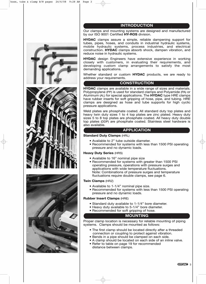
INTRODUCTIONOur clamps and mounting systems are designed and manufacturedby our ISO 9001 Certified HY-ROS division.
HYDAC clamps assure a simple, reliable dampening support fortubes, pipes, hoses, and conduits in industrial hydraulic systems,mobile hydraulic systems, process industries, and electricalconstruction. HYDAC clamps absorb shock, dampen vibration, andreduce noise in hydraulic systems.
HYDAC design Engineers have extensive experience in workingclosely with customers, in evaluating their requirements, anddeveloping custom clamp arrangements to satisfy the mostdemanding applications.
Whether standard or custom HYDAC products, we are ready toaddress your requirements.
CONSTRUCTIONHYDAC clamps are available in a wide range of sizes and materials.Polypropylene (PP) is used for standard clamps and Polyamide (PA) orAluminum (AL) for special applications. The HYDAC type HRE clampshave rubber inserts for soft gripping of hose, pipe, and tubing. HREclamps are designed as hose and tube supports for high cyclicpressure applications.
Weld plates are phosphate coated. All standard duty top plates andheavy twin duty sizes 1 to 4 top plates are zinc plated. Heavy dutysizes 5 to 8 top plates are phosphate coated. All heavy duty doubletop plates (DDP) are phosphate coated. Stainless steel hardware isalso available.
APPLICATIONStandard Duty Clamps (HRL)
• Available to 2” tube outside diameter.• Recommended for systems with less than 1500 PSI operating
pressure and no dynamic loads.
Heavy Duty Series (HRS)
• Available to 16” nominal pipe size• Recommended for systems with greater than 1500 PSI
operating pressure, operations with pressure surges andapplications with wide temperature fluctuations. Note: Combinations of pressure surges and temperaturefluctuations require double clamps, see page 6.
Twin Clamps (HRZ)
• Available to 1-1/4” nominal pipe size.• Recommended for systems with less than 1500 PSI operating
pressure and no dynamic loads.
Rubber Insert Clamps (HRE)
• Standard duty available to 1-1/4” bore diameter.• Heavy duty available to 5-1/4” bore diameter.• Recommended for soft gripping of hose.
MOUNTINGProper clamp location is necessary for reliable mounting of pipingsystems. Clamps should be mounted as follows:
• The first clamp should be located directly after a threaded connection or coupling to protect against vibration.
• Bends in a pipe should be clamped on each side.• A clamp should be located on each side of an inline valve.• Refer to table on page 19 for recommended
distance between clamps.
hose, tube & clamp B/W pages 24/6/08 9:28 AM Page 3
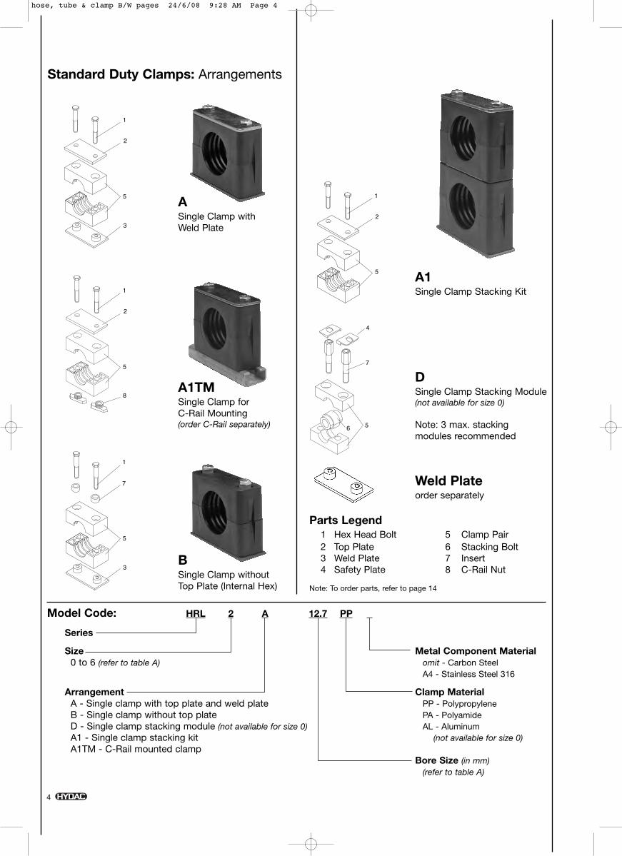
ASingle Clamp withWeld Plate
A1Single Clamp Stacking Kit
DSingle Clamp Stacking Module(not available for size 0)
Note: 3 max. stacking modules recommended
A1TMSingle Clamp for C-Rail Mounting(order C-Rail separately)
BSingle Clamp withoutTop Plate (Internal Hex)
4
Standard Duty Clamps: Arrangements
Model Code: HRL 2 A 12.7 PP
Series
Size Metal Component Material0 to 6 (refer to table A) omit - Carbon Steel
A4 - Stainless Steel 316
Arrangement Clamp MaterialA - Single clamp with top plate and weld plate PP - PolypropyleneB - Single clamp without top plate PA - PolyamideD - Single clamp stacking module (not available for size 0) AL - Aluminum A1 - Single clamp stacking kit (not available for size 0)A1TM - C-Rail mounted clamp
Bore Size (in mm)(refer to table A)
Parts Legend1 Hex Head Bolt 5 Clamp Pair2 Top Plate 6 Stacking Bolt3 Weld Plate 7 Insert4 Safety Plate 8 C-Rail Nut
Note: To order parts, refer to page 14
Weld Plateorder separately
hose, tube & clamp B/W pages 24/6/08 9:28 AM Page 4
5
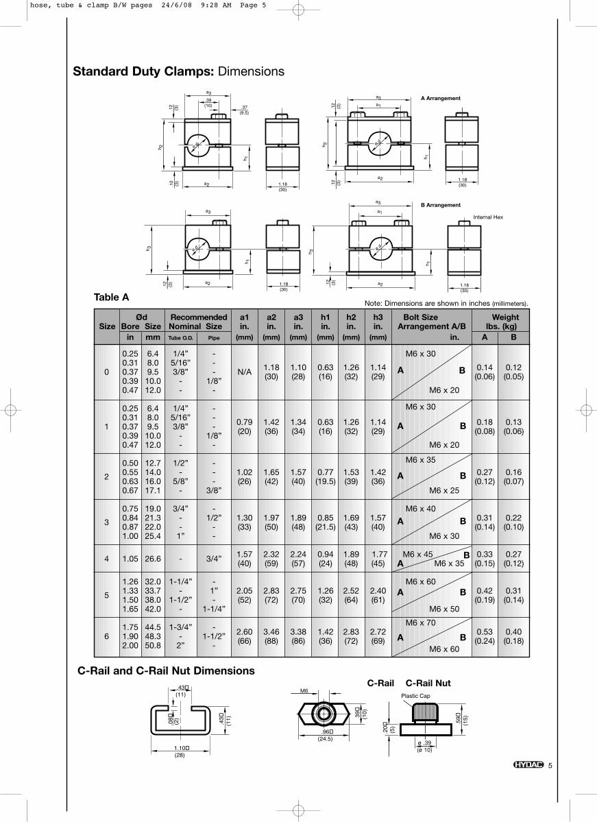
Standard Duty Clamps: Dimensions
Ød Recommended a1 a2 a3 h1 h2 h3 Bolt Size WeightSize Bore Size Nominal Size in. in. in. in. in. in. Arrangement A/B lbs. (kg)
in mm Tube O.D. Pipe (mm) (mm) (mm) (mm) (mm) (mm) in. A B
0.25 6.4 1/4” - M6 x 300.31 8.0 5/16” -
0 0.37 9.5 3/8” - N/A 1.18 1.10 0.63 1.26 1.14 0.14 0.12
0.39 10.0 - 1/8” (30) (28) (16) (32) (29) (0.06) (0.05)
0.47 12.0 - - M6 x 20
0.25 6.4 1/4” - M6 x 300.31 8.0 5/16” -
1 0.37 9.5 3/8” - 0.79 1.42 1.34 0.63 1.26 1.14 0.18 0.13
0.39 10.0 - 1/8” (20) (36) (34) (16) (32) (29) (0.08) (0.06)
0.47 12.0 - - M6 x 20
0.50 12.7 1/2” - M6 x 35
2 0.55 14.0 - - 1.02 1.65 1.57 0.77 1.53 1.42 0.27 0.160.63 16.0 5/8” - (26) (42) (40) (19.5) (39) (36) (0.12) (0.07)0.67 17.1 - 3/8” M6 x 25
0.75 19.0 3/4” - M6 x 40
3 0.84 21.3 - 1/2” 1.30 1.97 1.89 0.85 1.69 1.57 0.31 0.220.87 22.0 - - (33) (50) (48) (21.5) (43) (40) (0.14) (0.10)1.00 25.4 1” - M6 x 30
4 1.05 26.6 - 3/4” 1.57 2.32 2.24 0.94 1.89 1.77 M6 x 45 0.33 0.27(40) (59) (57) (24) (48) (45) M6 x 35 (0.15) (0.12)
1.26 32.0 1-1/4” - M6 x 60
5 1.33 33.7 - 1” 2.05 2.83 2.75 1.26 2.52 2.40 0.42 0.311.50 38.0 1-1/2” - (52) (72) (70) (32) (64) (61) (0.19) (0.14)1.65 42.0 - 1-1/4” M6 x 50
1.75 44.5 1-3/4” - M6 x 70
6 1.90 48.3 - 1-1/2” 2.60 3.46 3.38 1.42 2.83 2.72 0.53 0.40
2.00 50.8 2” - (66) (88) (86) (36) (72) (69)M6 x 60
(0.24) (0.18)
A B
A B
A B
A B
AB
A B
A B
a3
ø d
ø d
ø d
ø d
a3
a3
a3
h 1h 1
.39(10) .37
(9.5)
a2
.12 (3)
.12 (3)
h 2
1.18(30)
a1
h 1
1.18(30)
a2
.12 (3)
.12 (3)
h 2
1.18(30)
a1
h 1
a2.12 (3)
h 3
1.18(30)
a2.12 (3)
h 3
1.10 (28)
.43 (11)
.43
(11)
.20 (5) .5
9 (1
5)
Plastic Cap
.96 (24.5)
39
(10)
1/4" -20 UNC
.08 (2)
1.10 (28)
.43 (11)
.43
(11)
.20 (5) .5
9 (1
5)
Plastic Cap
.96 (24.5)
39
(10)
1/4" -20 UNC
.08 (2)
C-Rail and C-Rail Nut DimensionsC-Rail C-Rail Nut
Table ANote: Dimensions are shown in inches (millimeters).
Internal Hex
B Arrangement
A Arrangement
M6
hose, tube & clamp B/W pages 24/6/08 9:28 AM Page 5
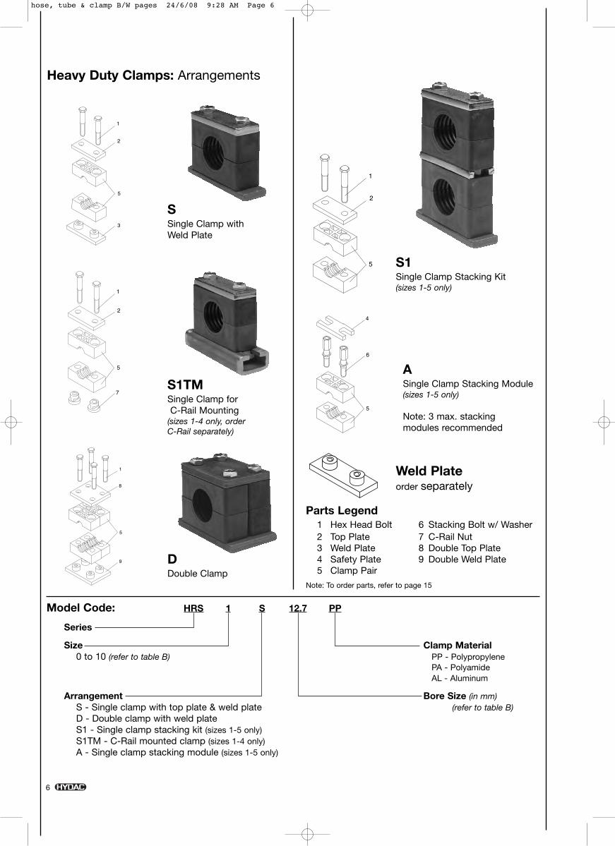
SSingle Clamp withWeld Plate
S1Single Clamp Stacking Kit (sizes 1-5 only)
ASingle Clamp Stacking Module(sizes 1-5 only)
Note: 3 max. stacking modules recommended
S1TMSingle Clamp forC-Rail Mounting
(sizes 1-4 only, order C-Rail separately)
DDouble Clamp
Heavy Duty Clamps: Arrangements
Model Code: HRS 1 S 12.7 PP
Series
Size Clamp Material0 to 10 (refer to table B) PP - Polypropylene
PA - PolyamideAL - Aluminum
Arrangement Bore Size (in mm)S - Single clamp with top plate & weld plate (refer to table B)D - Double clamp with weld plateS1 - Single clamp stacking kit (sizes 1-5 only)S1TM - C-Rail mounted clamp (sizes 1-4 only)A - Single clamp stacking module (sizes 1-5 only)
Parts Legend1 Hex Head Bolt 6 Stacking Bolt w/ Washer2 Top Plate 7 C-Rail Nut3 Weld Plate 8 Double Top Plate4 Safety Plate 9 Double Weld Plate5 Clamp Pair
Note: To order parts, refer to page 15
Weld Plateorder separately
6
hose, tube & clamp B/W pages 24/6/08 9:28 AM Page 6
7
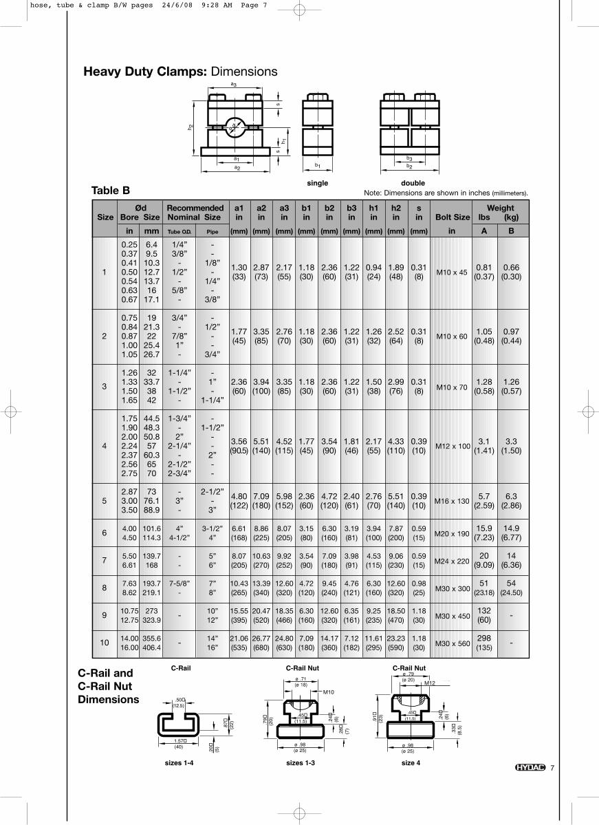
Ød Recommended a1 a2 a3 b1 b2 b3 h1 h2 s WeightSize Bore Size Nominal Size in in in in in in in in in Bolt Size lbs (kg)
in mm Tube O.D. Pipe (mm) (mm) (mm) (mm) (mm) (mm) (mm) (mm) (mm) in A B
0.25 6.4 1/4” -0.37 9.5 3/8” -0.41 10.3 - 1/8” 1.30 2.87 2.17 1.18 2.36 1.22 0.94 1.89 0.31 0.81 0.661 0.50 12.7 1/2” - (33) (73) (55) (30) (60) (31) (24) (48) (8) M10 x 45 (0.37) (0.30)0.54 13.7 - 1/4”0.63 16 5/8” -0.67 17.1 - 3/8”
0.75 19 3/4” -0.84 21.3 - 1/2”
2 0.87 22 7/8” - 1.77 3.35 2.76 1.18 2.36 1.22 1.26 2.52 0.31M10 x 60
1.05 0.97
1.00 25.4 1” - (45) (85) (70) (30) (60) (31) (32) (64) (8) (0.48) (0.44)
1.05 26.7 - 3/4”
1.26 32 1-1/4” -
3 1.33 33.7 - 1” 2.36 3.94 3.35 1.18 2.36 1.22 1.50 2.99 0.31M10 x 70
1.28 1.261.50 38 1-1/2” - (60) (100) (85) (30) (60) (31) (38) (76) (8) (0.58) (0.57)1.65 42 - 1-1/4”
1.75 44.5 1-3/4” -1.90 48.3 - 1-1/2”2.00 50.8 2” -
4 2.24 57 2-1/4” - 3.56 5.51 4.52 1.77 3.54 1.81 2.17 4.33 0.39M12 x 100
3.1 3.3
2.37 60.3 - 2” (90.5) (140) (115) (45) (90) (46) (55) (110) (10) (1.41) (1.50)
2.56 65 2-1/2” -2.75 70 2-3/4” -
2.87 73 - 2-1/2”5 3.00 76.1 3” - 4.80 7.09 5.98 2.36 4.72 2.40 2.76 5.51 0.39
M16 x 1305.7 6.3
3.50 88.9 - 3” (122) (180) (152) (60) (120) (61) (70) (140) (10) (2.59) (2.86)
6 4.00 101.6 4” 3-1/2” 6.61 8.86 8.07 3.15 6.30 3.19 3.94 7.87 0.59M20 x 190
15.9 14.94.50 114.3 4-1/2” 4” (168) (225) (205) (80) (160) (81) (100) (200) (15) (7.23) (6.77)
7 5.50 139.7 - 5” 8.07 10.63 9.92 3.54 7.09 3.98 4.53 9.06 0.59M24 x 220
20 146.61 168 - 6” (205) (270) (252) (90) (180) (91) (115) (230) (15) (9.09) (6.36)
8 7.63 193.7 7-5/8” 7” 10.43 13.39 12.60 4.72 9.45 4.76 6.30 12.60 0.98M30 x 300
51 548.62 219.1 - 8” (265) (340) (320) (120) (240) (121) (160) (320) (25) (23.18) (24.50)
9 10.75 273 - 10” 15.55 20.47 18.35 6.30 12.60 6.35 9.25 18.50 1.18M30 x 450
132 -12.75 323.9 12” (395) (520) (466) (160) (320) (161) (235) (470) (30) (60)
10 14.00 355.6 - 14” 21.06 26.77 24.80 7.09 14.17 7.12 11.61 23.23 1.18M30 x 560
298 -16.00 406.4 16” (535) (680) (630) (180) (360) (182) (295) (590) (30) (135)
a3
a1a2
ss
h 2
b1
h 1
b3b2
ø d
single double
.50 (12.5)
.20 (5)
3/8" -16 UNC
.87
(22)
1.57 (40)
.24 (6)
.28 (7)
.79
(20)
.45 (11.5)
7/16" -14 UNC
.24 (6)
.33
(8.5
)
.91
(23)
.45 (11.5)
C-Rail
sizes 1-4
C-Rail Nut C-Rail Nut
sizes 1-3 size 4
Heavy Duty Clamps: Dimensions
Note: Dimensions are shown in inches (millimeters).
C-Rail and C-Rail Nut Dimensions
Table B
M10
M12
hose, tube & clamp B/W pages 24/6/08 9:28 AM Page 7
8
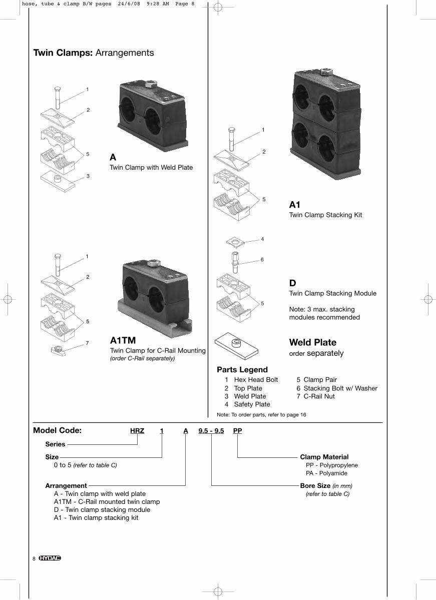
ATwin Clamp with Weld Plate
A1Twin Clamp Stacking Kit
DTwin Clamp Stacking Module
Note: 3 max. stacking modules recommended
A1TMTwin Clamp for C-Rail Mounting(order C-Rail separately)
Twin Clamps: Arrangements
Model Code: HRZ 1 A 9.5 - 9.5 PP
Series
Size Clamp Material0 to 5 (refer to table C) PP - Polypropylene
PA - Polyamide
Arrangement Bore Size (in mm)A - Twin clamp with weld plate (refer to table C)A1TM - C-Rail mounted twin clampD - Twin clamp stacking moduleA1 - Twin clamp stacking kit
Parts Legend1 Hex Head Bolt 5 Clamp Pair2 Top Plate 6 Stacking Bolt w/ Washer3 Weld Plate 7 C-Rail Nut4 Safety Plate
Note: To order parts, refer to page 16
Weld Plateorder separately
hose, tube & clamp B/W pages 24/6/08 9:28 AM Page 8
.20 (5) .5
1 (1
3).4
3 (1
0.8)
.94 (24)
5/16"-18 UNC
.96 (24.5)
39
(10)
1/4" -20 UNC
.20 (5) .5
9 (1
5)
Plastic Cap1.10 (28)
.43 (11)
.43
(11).08 (2)
C-Rail C-Rail Nut C-Rail Nut
size 1 sizes 2-5sizes 1-5
C-Rail and C-Rail Nut Dimensions
9
a3a1
a2h 2h 3
h 1
.20 (5) 1.18
(30)
ø dø d
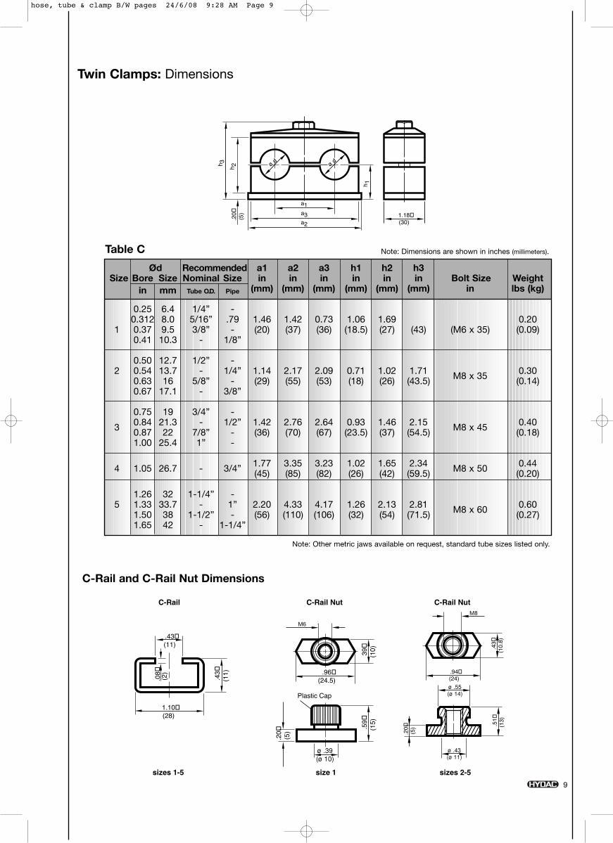
Twin Clamps: Dimensions
Note: Dimensions are shown in inches (millimeters).Table C
Ød Recommended a1 a2 a3 h1 h2 h3Size Bore Size Nominal Size in in in in in in Bolt Size Weight
in mm Tube O.D. Pipe (mm) (mm) (mm) (mm) (mm) (mm) in lbs (kg)
0.25 6.4 1/4” -0.312 8.0 5/16” .79 1.46 1.42 0.73 1.06 1.69 0.20
1 0.37 9.5 3/8” - (20) (37) (36) (18.5) (27) (43) (M6 x 35) (0.09)0.41 10.3 - 1/8”
0.50 12.7 1/2” -2 0.54 13.7 - 1/4” 1.14 2.17 2.09 0.71 1.02 1.71 M8 x 35 0.30
0.63 16 5/8” - (29) (55) (53) (18) (26) (43.5) (0.14)0.67 17.1 - 3/8”
0.75 19 3/4” -
3 0.84 21.3 - 1/2” 1.42 2.76 2.64 0.93 1.46 2.15 M8 x 45 0.400.87 22 7/8” - (36) (70) (67) (23.5) (37) (54.5) (0.18)1.00 25.4 1” -
4 1.05 26.7 - 3/4” 1.77 3.35 3.23 1.02 1.65 2.34 M8 x 50 0.44(45) (85) (82) (26) (42) (59.5) (0.20)
1.26 32 1-1/4” -5 1.33 33.7 - 1” 2.20 4.33 4.17 1.26 2.13 2.81 M8 x 60 0.60
1.50 38 1-1/2” - (56) (110) (106) (32) (54) (71.5) (0.27)1.65 42 - 1-1/4”
M6
M8
Note: Other metric jaws available on request, standard tube sizes listed only.
hose, tube & clamp B/W pages 24/6/08 9:28 AM Page 9
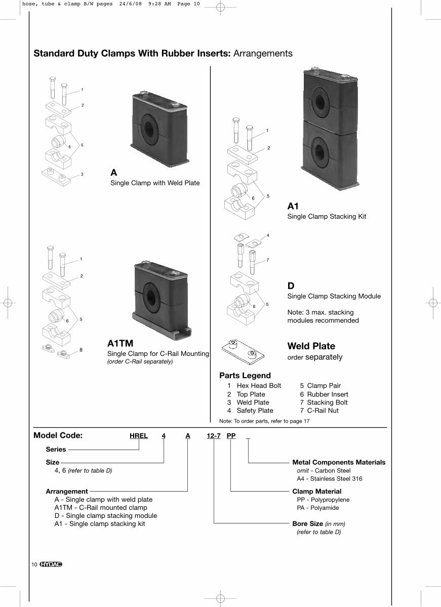
ASingle Clamp with Weld Plate
A1Single Clamp Stacking Kit
DSingle Clamp Stacking Module
Note: 3 max. stacking modules recommended
A1TMSingle Clamp for C-Rail Mounting(order C-Rail separately)
Standard Duty Clamps With Rubber Inserts: Arrangements
Model Code: HREL 4 A 12-7 PP
Series
Size Metal Components Materials4, 6 (refer to table D) omit - Carbon Steel
A4 - Stainless Steel 316
Arrangement Clamp MaterialA - Single clamp with weld plate PP - PolypropyleneA1TM - C-Rail mounted clamp PA - PolyamideD - Single clamp stacking moduleA1 - Single clamp stacking kit Bore Size (in mm)
(refer to table D)
Parts Legend1 Hex Head Bolt 5 Clamp Pair2 Top Plate 6 Rubber Insert3 Weld Plate 7 Stacking Bolt4 Safety Plate 7 C-Rail Nut
Note: To order parts, refer to page 17
Weld Plateorder separately
10
hose, tube & clamp B/W pages 24/6/08 9:28 AM Page 10
a1
ø d1
s
1.18 (30)
ø d
a2
h 1
a3
h 2s
ø d
2
1.10 (28)
.43 (11)
.43
(11)
.20 (5) .5
9 (1
5)
Plastic Cap
.96 (24.5)
39
(10)
1/4" -20 UNC
.08 (2)
C-Rail and C-Rail Nut Dimensions
C-Rail C-Rail Nut
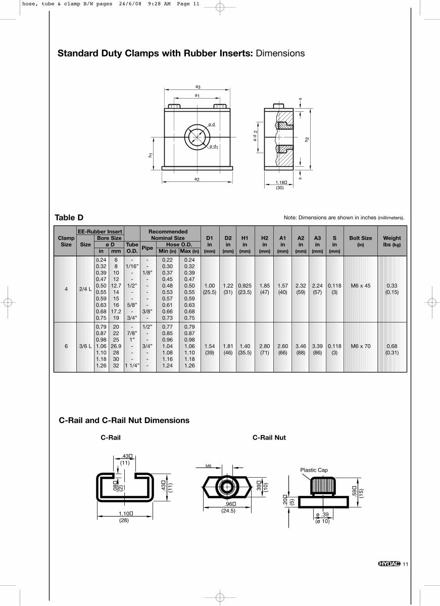
Standard Duty Clamps with Rubber Inserts: Dimensions
Note: Dimensions are shown in inches (millimeters).
EE-Rubber Insert RecommendedClamp Bore Size Nominal Size D1 D2 H1 H2 A1 A2 A3 S Bolt Size WeightSize Size ø D Tube
PipeHose O.D. in in in in in in in in (in) lbs (kg)
in mm O.D. Min (in) Max (in) (mm) (mm) (mm) (mm) (mm) (mm) (mm) (mm)
0.24 6 - - 0.22 0.240.32 8 1/16” - 0.30 0.320.39 10 - 1/8” 0.37 0.390.47 12 - - 0.45 0.47
4 2/4 L0.50 12.7 1/2” - 0.48 0.50 1.00 1.22 0.925 1.85 1.57 2.32 2.24 0.118 M6 x 45 0.330.55 14 - - 0.53 0.55 (25.5) (31) (23.5) (47) (40) (59) (57) (3) (0.15)0.59 15 - - 0.57 0.590.63 16 5/8” - 0.61 0.630.68 17.2 - 3/8” 0.66 0.680.75 19 3/4” - 0.73 0.75
0.79 20 - 1/2” 0.77 0.790.87 22 7/8” - 0.85 0.870.98 25 1” - 0.96 0.98
6 3/6 L 1.06 26.9 - 3/4” 1.04 1.06 1.54 1.81 1.40 2.80 2.60 3.46 3.39 0.118 M6 x 70 0.681.10 28 - - 1.08 1.10 (39) (46) (35.5) (71) (66) (88) (86) (3) (0.31)1.18 30 - - 1.16 1.181.26 32 1 1/4” - 1.24 1.26
Table D
11
M6
hose, tube & clamp B/W pages 24/6/08 9:28 AM Page 11
12
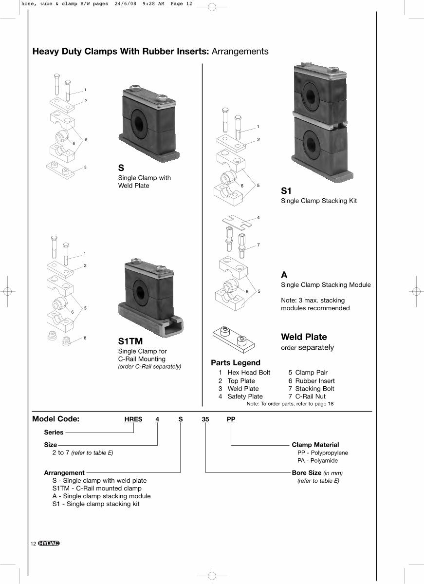
SSingle Clamp with Weld Plate
S1Single Clamp Stacking Kit
ASingle Clamp Stacking Module
Note: 3 max. stacking modules recommended
S1TMSingle Clamp for C-Rail Mounting(order C-Rail separately)
Heavy Duty Clamps With Rubber Inserts: Arrangements
Model Code: HRES 4 S 35 PP
Series
Size Clamp Material2 to 7 (refer to table E) PP - Polypropylene
PA - Polyamide
Arrangement Bore Size (in mm)S - Single clamp with weld plate (refer to table E)S1TM - C-Rail mounted clampA - Single clamp stacking moduleS1 - Single clamp stacking kit
Parts Legend1 Hex Head Bolt 5 Clamp Pair2 Top Plate 6 Rubber Insert3 Weld Plate 7 Stacking Bolt4 Safety Plate 7 C-Rail Nut
Note: To order parts, refer to page 18
Weld Plateorder separately
hose, tube & clamp B/W pages 24/6/08 9:28 AM Page 12
.50 (12.5)
.20 (5)
3/8" -16 UNC
.87
(22)
1.57 (40)
.24 (6)
.28 (7)
.79
(20)
.45 (11.5)
7/16" -14 UNC
.24 (6)
.33
(8.5
)
.91
(23)
.45 (11.5)
C-Rail
sizes 1-4
C-Rail Nut C-Rail Nut
sizes 1-3 size 4
a1 s
ba2
h 1
a3
h 2s
C-Rail and C-Rail Nut Dimensions
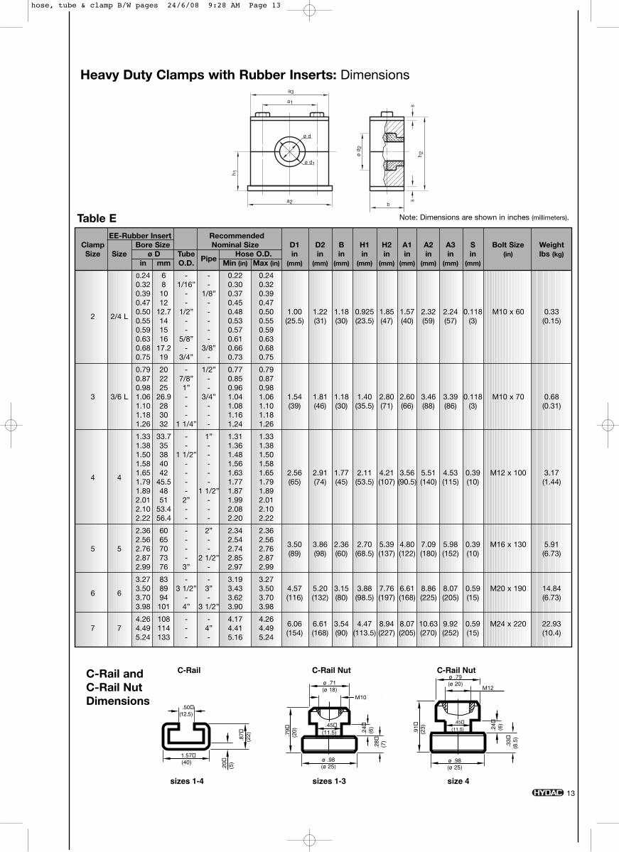
Heavy Duty Clamps with Rubber Inserts: Dimensions
Note: Dimensions are shown in inches (millimeters).
EE-Rubber Insert RecommendedClamp Bore Size Nominal Size D1 D2 B H1 H2 A1 A2 A3 S Bolt Size WeightSize Size ø D Tube
PipeHose O.D. in in in in in in in in in (in) lbs (kg)
in mm O.D. Min (in) Max (in) (mm) (mm) (mm) (mm) (mm) (mm) (mm) (mm) (mm)
0.24 6 - - 0.22 0.240.32 8 1/16” - 0.30 0.320.39 10 - 1/8” 0.37 0.390.47 12 - - 0.45 0.47
2 2/4 L0.50 12.7 1/2” - 0.48 0.50 1.00 1.22 1.18 0.925 1.85 1.57 2.32 2.24 0.118 M10 x 60 0.330.55 14 - - 0.53 0.55 (25.5) (31) (30) (23.5) (47) (40) (59) (57) (3) (0.15)0.59 15 - - 0.57 0.590.63 16 5/8” - 0.61 0.630.68 17.2 - 3/8” 0.66 0.680.75 19 3/4” - 0.73 0.75
0.79 20 - 1/2” 0.77 0.790.87 22 7/8” - 0.85 0.870.98 25 1” - 0.96 0.98
3 3/6 L 1.06 26.9 - 3/4” 1.04 1.06 1.54 1.81 1.18 1.40 2.80 2.60 3.46 3.39 0.118 M10 x 70 0.681.10 28 - - 1.08 1.10 (39) (46) (30) (35.5) (71) (66) (88) (86) (3) (0.31)1.18 30 - - 1.16 1.181.26 32 1 1/4” - 1.24 1.26
1.33 33.7 - 1” 1.31 1.331.38 35 - - 1.36 1.381.50 38 1 1/2” - 1.48 1.501.58 40 - - 1.56 1.58
4 41.65 42 - - 1.63 1.65 2.56 2.91 1.77 2.11 4.21 3.56 5.51 4.53 0.39 M12 x 100 3.171.79 45.5 - - 1.77 1.79 (65) (74) (45) (53.5) (107) (90.5) (140) (115) (10) (1.44)1.89 48 - 1 1/2” 1.87 1.892.01 51 2” - 1.99 2.012.10 53.4 - - 2.08 2.102.22 56.4 - - 2.20 2.22
2.36 60 - 2” 2.34 2.362.56 65 - - 2.54 2.56
3.50 3.86 2.36 2.70 5.39 4.80 7.09 5.98 0.39 M16 x 130 5.915 5 2.76 70 - - 2.74 2.76(89) (98) (60) (68.5) (137) (122) (180) (152) (10) (6.73)2.87 73 - 2 1/2” 2.85 2.87
2.99 76 3” - 2.97 2.99
3.27 83 - - 3.19 3.27
6 63.50 89 3 1/2” 3” 3.43 3.50 4.57 5.20 3.15 3.88 7.76 6.61 8.86 8.07 0.59 M20 x 190 14.843.70 94 - - 3.62 3.70 (116) (132) (80) (98.5) (197) (168) (225) (205) (15) (6.73)3.98 101 4” 3 1/2” 3.90 3.98
4.26 108 - - 4.17 4.266.06 6.61 3.54 4.47 8.94 8.07 10.63 9.92 0.59 M24 x 220 22.937 7 4.49 114 - 4” 4.41 4.49(154) (168) (90) (113.5) (227) (205) (270) (252) (15) (10.4)5.24 133 - - 5.16 5.24
Table E
13
M10
M12
hose, tube & clamp B/W pages 24/6/08 9:28 AM Page 13
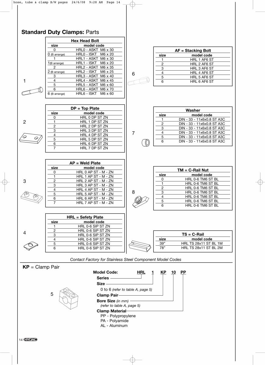
Hex Head Boltsize model code
0 HRL0 - ASKT M6 x 300 (B arrange) HRL0 - ISKT M6 x 20
1 HRL1 - ASKT M6 x 301(B arrange) HRL1 - ISKT M6 x 20
2 HRL2 - ASKT M6 x 352 (B arrange) HRL2 - ISKT M6 x 25
3 HRL3 - ASKT M6 x 404 HRL4 - ASKT M6 x 455 HRL5 - ASKT M6 x 606 HRL6 - ASKT M6 x 70
6 (B arrange) HRL6 - ISKT M6 x 60
DP = Top Platesize model code
0 HRL 0 DP ST ZN1 HRL 1 DP ST ZN2 HRL 2 DP ST ZN3 HRL 3 DP ST ZN4 HRL 4 DP ST ZN5 HRL 5 DP ST ZN6 HRL 6 DP ST ZN7 HRL 7 DP ST ZN
Standard Duty Clamps: Parts
AP = Weld Platesize model code
0 HRL 0 AP ST - M - ZN1 HRL 1 AP ST - M - ZN2 HRL 2 AP ST - M - ZN3 HRL 3 AP ST - M - ZN4 HRL 4 AP ST - M - ZN5 HRL 5 AP ST - M - ZN6 HRL 6 AP ST - M - ZN7 HRL 7 AP ST - M - ZN
TM = C-Rail Nutsize model code
0 HRL 0-6 TM6 ST BL1 HRL 0-6 TM6 ST BL2 HRL 0-6 TM6 ST BL3 HRL 0-6 TM6 ST BL4 HRL 0-6 TM6 ST BL5 HRL 0-6 TM6 ST BL6 HRL 0-6 TM6 ST BL
AF = Stacking Boltsize model code
1 HRL 1 AF6 ST 2 HRL 2 AF6 ST 3 HRL 3 AF6 ST 4 HRL 4 AF6 ST 5 HRL 5 AF6 ST 6 HRL 6 AF6 ST
Washersize model code
1 DIN - 33 - 11x6x0.8 ST A3C2 DIN - 33 - 11x6x0.8 ST A3C3 DIN - 33 - 11x6x0.8 ST A3C4 DIN - 33 - 11x6x0.8 ST A3C5 DIN - 33 - 11x6x0.8 ST A3C6 DIN - 33 - 11x6x0.8 ST A3C
HRL = Sefety Platesize model code
1 HRL 0-6 SIP ST ZN2 HRL 0-6 SIP ST ZN3 HRL 0-6 SIP ST ZN4 HRL 0-6 SIP ST ZN5 HRL 0-6 SIP ST ZN6 HRL 0-6 SIP ST ZN
TS = C-Railsize model code39” HRL TS 28x11 ST BL 1M78” HRL TS 28x11 ST BL 2M
1
2
3
6
7
5
8
4
Model Code: HRL 1 KP 10 PPSeriesSize
0 to 6 (refer to table A, page 5)
Clamp PairBore Size (in mm)
(refer to table A, page 5)
Clamp MaterialPP - PolypropylenePA - PolyamideAL - Aluminum
KP = Clamp Pair
Contact Factory for Stainless Steel Component Model Codes
14
hose, tube & clamp B/W pages 24/6/08 9:28 AM Page 14
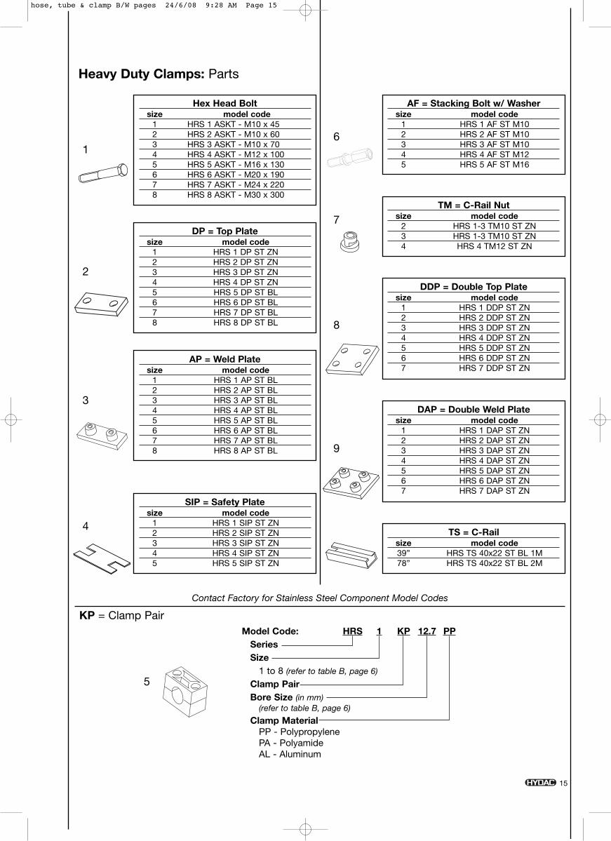
Hex Head Boltsize model code
1 HRS 1 ASKT - M10 x 452 HRS 2 ASKT - M10 x 603 HRS 3 ASKT - M10 x 704 HRS 4 ASKT - M12 x 1005 HRS 5 ASKT - M16 x 1306 HRS 6 ASKT - M20 x 1907 HRS 7 ASKT - M24 x 2208 HRS 8 ASKT - M30 x 300
5
Model Code: HRS 1 KP 12.7 PPSeriesSize
1 to 8 (refer to table B, page 6)
Clamp PairBore Size (in mm)
(refer to table B, page 6)
Clamp MaterialPP - PolypropylenePA - PolyamideAL - Aluminum
KP = Clamp Pair
Heavy Duty Clamps: Parts
DP = Top Platesize model code
1 HRS 1 DP ST ZN2 HRS 2 DP ST ZN3 HRS 3 DP ST ZN4 HRS 4 DP ST ZN5 HRS 5 DP ST BL6 HRS 6 DP ST BL7 HRS 7 DP ST BL8 HRS 8 DP ST BL
AP = Weld Platesize model code
1 HRS 1 AP ST BL2 HRS 2 AP ST BL3 HRS 3 AP ST BL4 HRS 4 AP ST BL5 HRS 5 AP ST BL6 HRS 6 AP ST BL7 HRS 7 AP ST BL8 HRS 8 AP ST BL
TM = C-Rail Nutsize model code
2 HRS 1-3 TM10 ST ZN3 HRS 1-3 TM10 ST ZN4 HRS 4 TM12 ST ZN
DAP = Double Weld Platesize model code
1 HRS 1 DAP ST ZN2 HRS 2 DAP ST ZN3 HRS 3 DAP ST ZN4 HRS 4 DAP ST ZN5 HRS 5 DAP ST ZN6 HRS 6 DAP ST ZN7 HRS 7 DAP ST ZN
DDP = Double Top Platesize model code
1 HRS 1 DDP ST ZN2 HRS 2 DDP ST ZN3 HRS 3 DDP ST ZN4 HRS 4 DDP ST ZN5 HRS 5 DDP ST ZN6 HRS 6 DDP ST ZN7 HRS 7 DDP ST ZN
AF = Stacking Bolt w/ Washersize model code
1 HRS 1 AF ST M102 HRS 2 AF ST M103 HRS 3 AF ST M104 HRS 4 AF ST M125 HRS 5 AF ST M16
SIP = Safety Platesize model code
1 HRS 1 SIP ST ZN2 HRS 2 SIP ST ZN3 HRS 3 SIP ST ZN4 HRS 4 SIP ST ZN5 HRS 5 SIP ST ZN
TS = C-Railsize model code39” HRS TS 40x22 ST BL 1M78” HRS TS 40x22 ST BL 2M
1
2
3
6
7
9
8
4
Contact Factory for Stainless Steel Component Model Codes
15
hose, tube & clamp B/W pages 24/6/08 9:28 AM Page 15

Twin Clamps: Parts
Hex Head Boltsize model code
1 HRZ 1 - ASKT - M6 x 352 HRZ 2 - ASKT - M8 x 353 HRZ 3 - ASKT - M8 x 454 HRZ 4 - ASKT - M8 x 505 HRZ 5 - ASKT - M8 x 60
DP = Top Platesize model code
1 HRZ 1 DP ST ZN2 HRZ 2 DP ST ZN3 HRZ 3 DP ST ZN4 HRZ 4 DP ST ZN5 HRZ 5 DP ST BL
AP = Weld Platesize model code
1 HRZ 1 AP ST ZN2 HRZ 2 AP ST ZN3 HRZ 3 AP ST ZN4 HRZ 4 AP ST ZN5 HRZ 5 AP ST ZN
TM = C-Rail Nutsize model code
1 HRZ 1 TM6 ST2 HRZ 2/5 TM8 ST 3 HRZ 2/5 TM8 ST 4 HRZ 2/5 TM8 ST 5 HRZ 2/5 TM8 ST
AF = Stacking Bolt w/ Washersize model code
1 HRZ 1 AF 6 ST ZN2 HRZ 2 AF 8 ST ZN3 HRZ 3 AF 8 ST ZN4 HRZ 2 AF 8 ST ZN5 HRZ 2 AF 8 ST ZN
SIP = Safety Platesize model code
1 HRZ 1 SIP ST ZN2 HRZ 2/5 SIP ST ZN3 HRZ 2/5 SIP ST ZN4 HRZ 2/5 SIP ST ZN5 HRZ 2/5 SIP ST ZN
TS = C-Railsize model code39” HRS TS 28x11 ST BL 1M78” HRS TS 28x11 ST BL 2M
1
2
3
6
7
4
Contact Factory for Stainless Steel Component Model Codes
16
5
Model Code: HRZ 1 KP 9.5-9.5 PPSeriesSize
0 to 5 (refer to table C, page 9)
Clamp PairBore Size (in mm)
(refer to table C, page 9)
Clamp MaterialPP - PolypropylenePA - Polyamide
KP = Clamp Pair
hose, tube & clamp B/W pages 24/6/08 9:28 AM Page 16

17
5 6
Model Code: HRL 4 KP PPSeriesSize
4, 6 (refer to table D, page 11)
Clamp PairClamp Material
PP - PolypropylenePA - Polyamide
Model Code: HREL 2/4 L EE 12SeriesSize
2/4 L, 3/6 L (refer to table D, page 11)
Rubber InsertBore Size (in mm)
(refer to table D, page 11)
KP = Clamp Pair EE = Rubber Insert
Hex Head Boltsize model code
4 HRL 4 - ASKT - M6 x 456 HRL 6 - ASKT - M6 x 70
DP = Top Platesize model code
4 HRL 4 DP ST ZN6 HRL 6 DP ST ZN
Standard Duty Clamps with Rubber Inserts: Parts
AP = Weld Platesize model code
4 HRL 4 AP ST M ZN6 HRL 6 AP ST M ZN
TM = C-Rail Nutsize model code
4 HRL 0-6 TM 6 ST M ZN6 HRL 0-6 TM 6 ST M ZN
AF = Stacking Boltsize model code
4 HRL 4 AF 6 ST ZN6 HRL 6 AF 6 ST ZN
HRL = Safety Platesize model code
1 HRL 0-6 SIP ST ZN2 HRL 0-6 SIP ST ZN3 HRL 0-6 SIP ST ZN4 HRL 0-6 SIP ST ZN5 HRL 0-6 SIP ST ZN6 HRL 0-6 SIP ST ZN
TS = C-Railsize model code39” HRL TS 28x11 ST BL 1M78” HRL TS 28x11 ST BL 2M
1
2
3
7
8
4
Contact Factory for Stainless Steel Component Model Codes
hose, tube & clamp B/W pages 24/6/08 9:28 AM Page 17
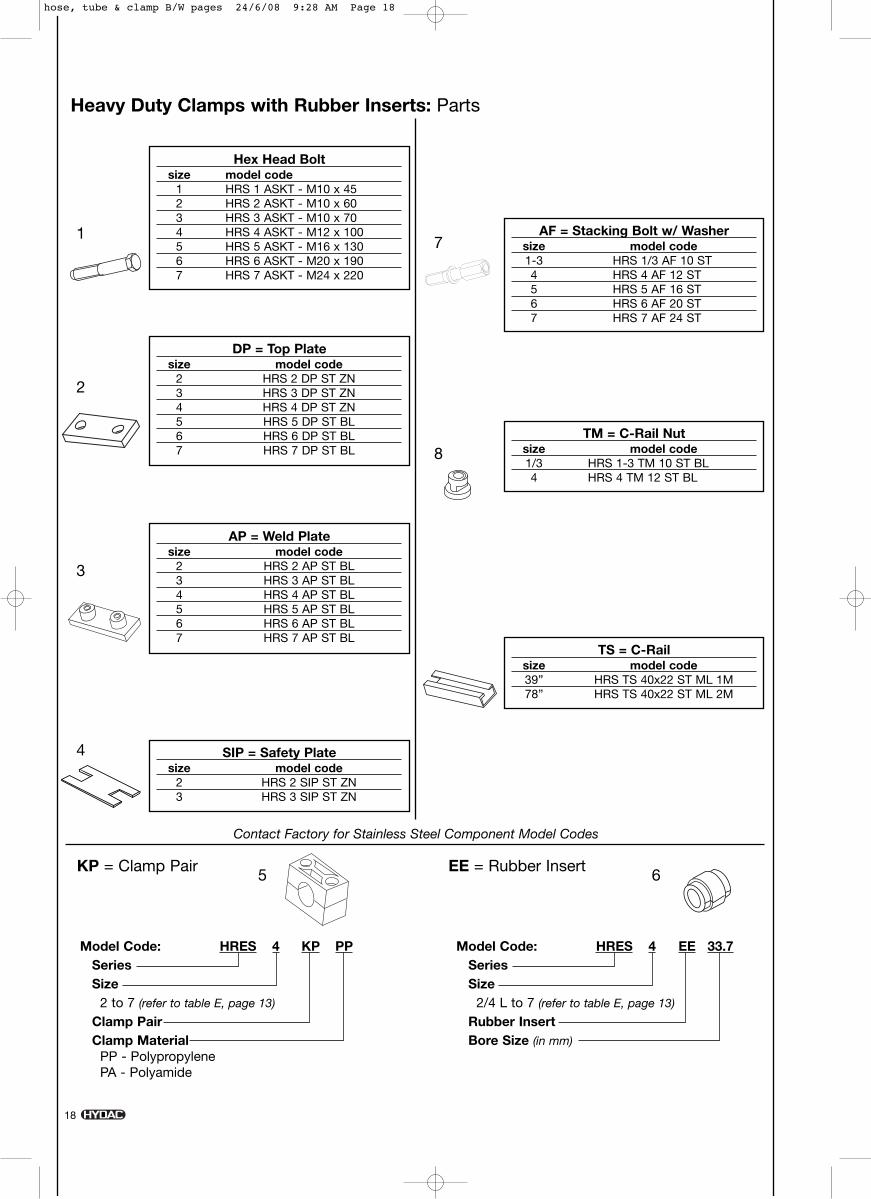
Heavy Duty Clamps with Rubber Inserts: Parts
Hex Head Boltsize model code
1 HRS 1 ASKT - M10 x 452 HRS 2 ASKT - M10 x 603 HRS 3 ASKT - M10 x 704 HRS 4 ASKT - M12 x 1005 HRS 5 ASKT - M16 x 1306 HRS 6 ASKT - M20 x 1907 HRS 7 ASKT - M24 x 220
DP = Top Platesize model code
2 HRS 2 DP ST ZN3 HRS 3 DP ST ZN4 HRS 4 DP ST ZN5 HRS 5 DP ST BL6 HRS 6 DP ST BL7 HRS 7 DP ST BL
AP = Weld Platesize model code
2 HRS 2 AP ST BL3 HRS 3 AP ST BL4 HRS 4 AP ST BL5 HRS 5 AP ST BL6 HRS 6 AP ST BL7 HRS 7 AP ST BL
TM = C-Rail Nutsize model code1/3 HRS 1-3 TM 10 ST BL4 HRS 4 TM 12 ST BL
AF = Stacking Bolt w/ Washersize model code1-3 HRS 1/3 AF 10 ST 4 HRS 4 AF 12 ST5 HRS 5 AF 16 ST6 HRS 6 AF 20 ST7 HRS 7 AF 24 ST
SIP = Safety Platesize model code
2 HRS 2 SIP ST ZN3 HRS 3 SIP ST ZN
TS = C-Railsize model code39” HRS TS 40x22 ST ML 1M78” HRS TS 40x22 ST ML 2M
1
2
3
7
5 6
8
4
Model Code: HRES 4 KP PPSeriesSize
2 to 7 (refer to table E, page 13)
Clamp PairClamp Material
PP - PolypropylenePA - Polyamide
Model Code: HRES 4 EE 33.7SeriesSize
2/4 L to 7 (refer to table E, page 13)
Rubber InsertBore Size (in mm)
KP = Clamp Pair EE = Rubber Insert
Contact Factory for Stainless Steel Component Model Codes
18
hose, tube & clamp B/W pages 24/6/08 9:28 AM Page 18
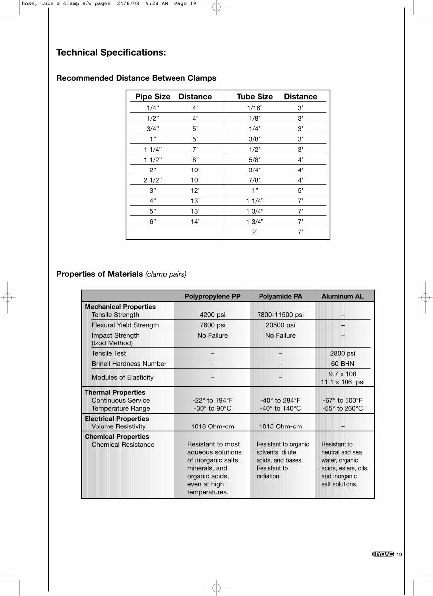
Technical Specifications:
Properties of Materials (clamp pairs)
Recommended Distance Between Clamps
Pipe Size Distance Tube Size Distance1/4” 4’ 1/16” 3’
1/2” 4’ 1/8” 3’
3/4” 5’ 1/4” 3’
1” 5’ 3/8” 3’
1 1/4” 7’ 1/2” 3’
1 1/2” 8’ 5/8” 4’
2” 10’ 3/4” 4’
2 1/2” 10’ 7/8” 4’
3” 12’ 1” 5’
4” 13’ 1 1/4” 7’
5” 13’ 1 3/4” 7’
6” 14’ 1 3/4” 7’
2’ 7’
Resistant to mostaqueous solutionsof inorganic salts,minerals, andorganic acids,even at hightemperatures.
Resistant to organicsolvents, diluteacids, and bases.Resistant toradiation.
Resistant toneutral and seawater, organicacids, esters, oils,and inorganic salt solutions.
Polypropylene PP Polyamide PA Aluminum AL
Mechanical PropertiesTensile Strength 4200 psi 7800-11500 psi –
Flexural Yield Strength 7600 psi 20500 psi –
Impact Strength No Failure No Failure –(Izod Method)
Tensile Test – – 2800 psi
Brinell Hardness Number – – 60 BHN
Modules of Elasticity – – 9.7 x 10811.1 x 106 psi
Thermal PropertiesContinuous Service -22° to 194°F -40° to 284°F -67° to 500°FTemperature Range -30° to 90°C -40° to 140°C -55° to 260°C
Electrical PropertiesVolume Resistivity 1018 Ohm-cm 1015 Ohm-cm –
Chemical PropertiesChemical Resistance
19
hose, tube & clamp B/W pages 24/6/08 9:28 AM Page 19