
HORIZONTAL CLOSE COUPLED VERTICAL FLANGE MOUNTED FLEXIBLE ... · HORIZONTAL CLOSE COUPLED VERTICAL...
20
Section E41•T41 Page 501 Dated October 2010 97-4622-01-588 E41•T41 SERIES Pump Manual HORIZONTAL CLOSE COUPLED VERTICAL FLANGE MOUNTED FLEXIBLE COUPLED
Transcript of HORIZONTAL CLOSE COUPLED VERTICAL FLANGE MOUNTED FLEXIBLE ... · HORIZONTAL CLOSE COUPLED VERTICAL...
Section E41•T41 Page 501Dated October 2010
97-4622-01-588
E41•T41 SERIES
Pump ManualHORIZONTAL CLOSE COUPLEDVERTICAL FLANGE MOUNTEDFLEXIBLE COUPLED
E41•T41 SERIES
HORIZONTAL CLOSE COUPLED PUMPSVERTICAL FLANGE MOUNTED CLOSE COUPLED PUMPSFLEXIBLE COUPLED PUMPS
1.General InstructionsGeneral Instructions1.General Instructions1.
Section E41•T41 Page 502Dated October 2010
A. Inspection of EquipmentB. StorageC. Placing Stored Pumps Into ServiceD. Application ConsiderationsE. Recommended Spare Parts
When properly installed and given reasonable care and maintenance, regenerative turbine pumps should operate satisfactorily for many years. Because of the high differential pres-sures expected in a regenerative turbine pump, close running clear-ances are used to reduce internal losses. Abrasive particles, even microscopic ones, in high enough concentrations, can open up the close clearances between internal components. For critical services it is recommended that you keep an identical pump for stand-by use.
1A Inspection of EquipmentImmediately upon receipt of the shipment, inspect the equipment for damage or missing components. Check the shipping manifest and report any damage or shortage to the Transportation Company’s local agent. Inspect the crate and any wrapping material before discarding. Parts or accessories are sometimes wrapped individually or fastened to the skid.
Put the instructions that came with the shipment in a safe place where they will be available to those who will be using them for installation and service.
1B StorageIf the pump is to be stored before use, it should be inspected as de-scribed in 1A, recrated and stored in a dry location. Standard shipping containers are not suitable for out-door storage. In some areas, it may be necessary to cover the pump’s exterior surface with oil or other rust inhibiting coating. All units are tested at the factory with a water/corrosion inhibitor solution, some of which will remain inside the pump upon receipt. If units are fl ushed out prior to stor-age, this inhibitor will be removed
and proper care must be taken to prevent product deterioration from improper storage.
For storage beyond 30 days, a corro-sion inhibiting protective fl uid should be added to the internal pump cavi-ties. Fluids used in the pump should be selected for compatibility with pump materials. This is very impor-tant when optional seal and gasket materials have been used. Protective caps on the inlet and outlets should also be used. Caps alone are not suf-fi cient protection.
1C Placing Stored Pumps Into ServiceSpecial care must be taken when placing stored pumps into service. First clean the outside and fl ush out the inside with a process compatible fl uid. Try to turn the pump using the coupling or shaft. On close coupled units, access to the shaft is between the pump and motor. A vise grip or other plier type gripping device may be used directly on the shaft. Apply-ing torque to the motor fan blades is not recommended. If the impeller does not break loose immediately, fi ll the pump with a process compatible fl uid and try again in a few hours.
If this fails, loosen only the pump cover thru bolts clamping the assem-bly together, one full turn, no more. Fill the pump with fl uid. Apply torque, 50 foot pounds maximum, to the shaft. The pump should turn before 50 foot pounds is reached. If you are successful at breaking loose the unit, continue turning the pump while retightening the thru bolts to their original positions.
If the unit still won’t turn over, DO NOT apply further force. Refer to the Disassembly/Reassembly Instruc-tions in Section 5 to determine the cause of the problem.
1D Application Considerations1D1 Electrical WiringAll electrical equipment and wiring should conform to local and National Electrical Codes. Use the motor
manufacturer’s instructions for con-necting the motor. Note the correct rotation and wiring diagrams on the assembly. Make sure the motor rota-tion and speed matches that required for the pump. When making electrical connections to motors provided with threaded stud electrical terminals, the recommended torque should be 13-16 inch-lbs. Applying torque in excess of this range may cause damage.
1D2 Construction MaterialsWhile it is reasonable to assume that good judgement has been used in selecting all the materials in the pump for compatibility with process fl uids, actual conditions sometimes vary from original specifi cations. Also, typical material selection charts do not consider all the temperature, pressure, and fl uid variables. The customer’s engineer should be con-sulted for fi nal judgement on the best materials for critical process applica-tions.
1D3 ValvesThe fi rst valve to be considered for a regenerative turbine pumping system might be a pressure relief valve. Because this type of pump has a horsepower requirement similar to that of a positive displacement pump (constantly rising hp along with pres-sure increases) a relief valve can be effectively used to limit horsepower. This is helpful when a non-overload-ing motor is specifi ed. It can be of critical importance if the system fl ow rate can vary widely. There are almost no circumstances where a fl ow modulating valve will work suc-cessfully in a regenerative turbine pumping system. The steep pump-ing characteristic, typical of these pumps, produces very large pressure changes with small variations in fl ow rate. As a result, the modulating fl ow from the valve introduces sharp pres-sure shock waves that shorten pump life and may cause damage to other pieces of equipment in the system.
A swing check valve is recommended in the suction line even when the pump inlet is only slightly higher than
Section E41•T41 Page 503Dated October 2010
the fl uid source. It should be the same size as the pump inlet or sized based on reasonable fl uid friction losses.
A foot valve is recommended when lifting fl uid from a sump. This will save wear and tear on any pump, even those equipped with self prim-ing capability.
A strainer is recommended imme-diately ahead of the pump on any newly constructed system if there is a possability that foreign material large enough to damage pump clearances may remain even though the piping has been fl ushed.
Valves in the outlet piping of a regen-erative turbine pump should always be open as far as possible when the pump is started. This will reduce the start-up load on the pump and motor. Never start the pump with the discharge valve closed.
Inlet valving should be open when starting any pumping system. With-out some fl uid in the pump, it can gall and lock up the impellers. Violent pump failure will result from contin-ued operation with the inlet valve closed.
1D4 PrimingRegardless of whether self-priming equipment is used or not, always fi ll the pump and vent it of air before starting, for best seal and pump life. Under most circumstances, regener-ative turbine pumps can be made to self-prime as long as a small amount of fl uid can be recirculated through the impeller and the fl uid doesn’t heat up noticeably.
1D5 NPSH (Net Positive Suction Head)The NPSH required varies with every size and capacity of pump. The NPSH required by your unit can be obtained from the performance curves or from your MTH representa-tive.
If the NPSH available is not equal to or greater than that required by the pump, it must be increased or a different pump selected. The usual method for increasing NPSH is to raise the static head on the pump in-let, (Hs). By defi nition, NPSH means:
“net positive suction head” above the vapor pressure of the pumped liquid available at the centerline of the pump. It should always be given in feet of pumped liquid. The NPSH is actually a measurement of the amount of energy available in the pumped liquid to produce the required absolute entrance velocity in the pump. If a pump requires more energy (or NPSH) than is available at a given capacity, the pressure at the inlet will fall below the vapor pres-sure of the pumped liquid and loss of performance will result as the liquid vaporizes.
Ps = Pressure in the suction vessel in PSIA.Pvp = Vapor pressure of the pumped fl uid in PSIA.Hs = Static height of the pumped fl uid above (+) or below (-) the centerline of the pump in feet.Hf = All friction losses from the vessel to the pump in feet.
NPSH = 2.31( )+ Hs- Hf
For boiling liquids, Ps and Pvp are equal. This item then becomes zero and can be omitted from the equa-tion.
1D6 NoiseRegenerative turbine pumps typically produce a high pitched whine that increases in intensity as the differen-tial pressure produced in the pump increases. While high frequency sound is attenuated more easily than lower frequencies, piping structures and the fl uids in them readily transmit noise. Motors, bearings, and other rotating components add to the noise and sometimes create objectionable harmonics.
Adequate support for the inlet and discharge piping is important for noise reduction.
1D7 FreezingWhen ambient temperatures drop be-low the freezing point of the fl uid in a pump, consideration should be given to heating, insulating, or draining the pump. If you choose to drain the pump, and it will only be for a short period, fi rst remove the drain plugs,
then drain the inlet and outlet lines. Carefully blow out the pump with compressed air to clear all internal cavities of fl uid.
1E Recommended Spare PartsFOR CRITICAL SERVICES - a duplex installation, with two identical pumping units in parallel, is the safest and many times the most cost effec-tive choice.
FOR IMPORTANT SERVICES - a standby pump, ready for installation is advised.
Special pricing and new pump war-ranty is offered for factory rebuilding. Turn around time can be as short as one or two days for standard models.
FOR ROUTINE MAINTENANCE - only the mechanical seals and a complete set of “O” ring gaskets are recommended. Should additional components show wear, they are available from stock at the factory.
FOR SERVICING A PUMP THAT DOES NOT PRODUCE RATED HEAD - mechanical seals, “O” ring gaskets, impeller, motor bracket, and cover.
FOR REBUILDING A PUMP - all the components required for servicing, plus bearings, shaft, and drive keys for fl exible coupled pumps, should be obtained. A factory rebuild should be considered whenever your disassem-bly indicates rebuilding is necessary, as this is usually more economical.
The factory recommendation for spare parts are all of those listed for rebuilding a pump, and are shown on the exploded view drawings for each individual type of pump.
PNPSH = 2.31( )+ H
PNPSH = 2.31( )+ HNPSH = 2.31( )+ Hs NPSH = 2.31( )+ H
- PNPSH = 2.31( )+ H
- PNPSH = 2.31( )+ HNPSH = 2.31( )+ HvpNPSH = 2.31( )+ H sp. gr.NPSH = 2.31( )+ H sp. gr.NPSH = 2.31( )+ HNPSH = 2.31( )+ H
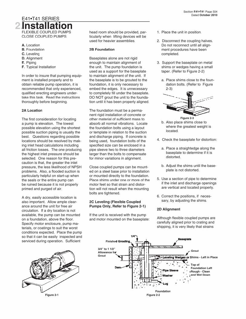
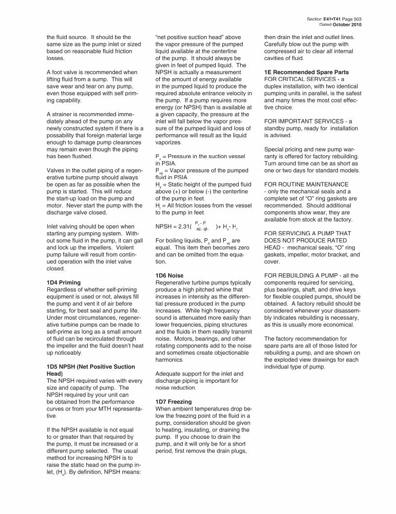
Figure 2-2Foundation
1/4”1/4”
Finished GroutingFinished Grouting
3/4” to 1 1/2” 3/4” to 1 1/2” Allowance for Allowance for Grout
DamDam
BaseplateBaseplate
Grout
Leveling Wedges or Shims - Left in PlaceLeveling Wedges or Shims - Left in Place
Pipe Sleeve
Washer
Lug
Top of Foundation Left Rough - Clean and Wet Down
Figure 2-3 b. Also place shims close to
where the greatest weight is located.
4. Check the baseplate for distortion:
a. Place a straightedge along the baseplate to determine if it is distorted.
b. Adjust the shims until the base-plate is not distorted.
5. Use a section of pipe to determine if the inlet and discharge openings are vertical and located properly.
6. Correct the positions, if neces-sary, by adjusting the shims.
2D Alignment
Although fl exible coupled pumps are carefully aligned prior to crating and shipping, it is very likely that strains
Figure 2-1
Section E41•T41 Page 504Dated October 2010
Installation2.E41•T41 SERIES
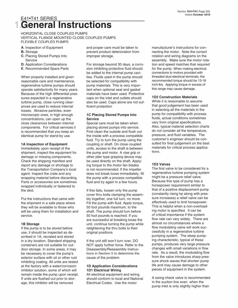
FLEXIBLE COUPLED PUMPSCLOSE COUPLED PUMPS
A. LocationB. FoundationC. LevelingD. AlignmentE. PipingF. Typical Installation
In order to insure that pumping equip-ment is installed properly and to obtain reliable pump operation, it is recommended that only experienced, qualifi ed erecting engineers under-take this task. Read the instructions thoroughly before beginning.
2A Location
The fi rst consideration for locating a pump is elevation. The lowest possible elevation using the shortest possible suction piping is usually the best. Questions regarding possible locations should be resolved by mak-ing inlet head calculations including all friction losses. The one producing the highest inlet pressure should be selected. One reason for this pre-caution is that, the greater the inlet pressure, the less likelihood of NPSH problems. Also, a fl ooded suction is particularly helpful on start-up when the seals or the entire pump can be ruined because it is not properly primed and purged of air.
A dry, easily accessible location is also important. Allow ample clear-ance around the unit for free air circulation. If a dry location is not available, the pump can be mounted on a foundation, above the fl oor. Specify motor enclosure, pump ma-terials, or coatings to suit the worst conditions expected. Place the pump so that it can be easily inspected and serviced during operation. Suffi cient
head room should be provided, par-ticularly when lifting devices will be used for heavier assemblies.
2B Foundation
Baseplates alone are not rigid enough to maintain alignment of the unit. The pump foundation is used as a support for the baseplate to maintain alignment of the unit. If the baseplate is to be grouted to the foundation, it is only necessary to embed the edges. It is unnecessary to completely fi ll under the baseplate. DO NOT grout the unit to the founda-tion until it has been properly aligned.
The foundation must be a perma-nent rigid installation of concrete or other material of suffi cient mass to absorb all normal vibrations. Locate the foundation bolts using a layout or template in relation to the suction and discharge piping. If concrete is being used, foundation bolts of the specifi ed size can be enclosed in a pipe sleeve two to three diameters larger than the bolts to compensate for minor variations in alignment.
Close coupled pumps can be mount-ed on a steel base prior to installation or mounted directly to the foundation. Place shims under one or more of the motor feet so that strain and distor-tion will not result when the mounting bolts are tightened.
2C Leveling (Flexible Coupled Pumps Only, Refer to Figure 2-1)
If the unit is received with the pump and motor mounted on the baseplate:
1. Place the unit in position.
2. Disconnect the coupling halves. Do not reconnect until all align-ment procedures have been completed.
3. Support the baseplate on metal shims or wedges having a small taper. (Refer to Figure 2-2)
a. Place shims close to the foun-dation bolts. (Refer to Figure 2-3)
1. Using a micrometer or caliper, measure from the outside of one fl ange to the outside of the other at intervals around the periphery of the coupling. DO NOT rotate the coupling.
2. Determine the maximum (B) and minimum (C) dimensions.
3. If the difference between the maximum and minimum exceeds the Angular dimension in Chart 1 for your sleeve size, loosen the motor or pump and place thin metal shims under the motor or pump feet until the misalignment is corrected.
4. Torque down the motor or pump.
5. Recheck the parallel alignment above.
CHART 1 COUPLING TYPES JE, J, S
MAX. RPM & ALLOWABLE MISALIGNMENT
SLEEVE SIZE
MAXIMUM RPM
PARALLELA
ANGULARB-C
3 9200 .010 .035
4 7600 .010 .043
5 7600 .015 .056
6 6000 .015 .070
If the parallel or angular misalign-ment is great, this is an indication of baseplate distortion and must be cor-rected fi rst, refer to 2C Leveling.
After all leveling and alignment op-erations have been completed, piping can begin. After the piping has been completed, refer to 2E1 Piping Align-ment. Alignment of the unit must be rechecked to make certain that no piping strains are causing distortion.
Section E41•T41 Page 505Dated October 2010
Figure 2-4
Figure 2-5 B
C
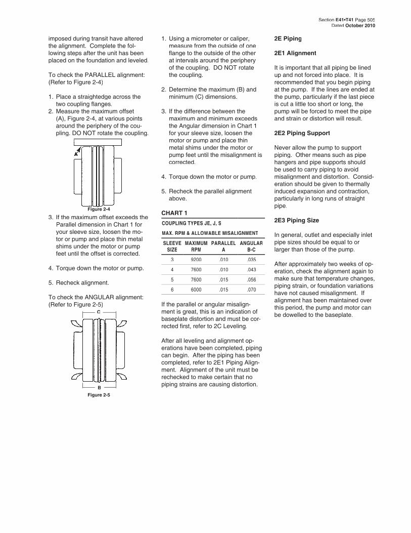
imposed during transit have altered the alignment. Complete the fol-lowing steps after the unit has been placed on the foundation and leveled.
To check the PARALLEL alignment: (Refer to Figure 2-4)
1. Place a straightedge across the two coupling fl anges.
2. Measure the maximum offset (A), Figure 2-4, at various points around the periphery of the cou-pling. DO NOT rotate the coupling.
3. If the maximum offset exceeds the Parallel dimension in Chart 1 for your sleeve size, loosen the mo-tor or pump and place thin metal shims under the motor or pump feet until the offset is corrected.
4. Torque down the motor or pump.
5. Recheck alignment.
To check the ANGULAR alignment: (Refer to Figure 2-5)
A
2E Piping
2E1 Alignment
It is important that all piping be lined up and not forced into place. It is recommended that you begin piping at the pump. If the lines are ended at the pump, particularly if the last piece is cut a little too short or long, the pump will be forced to meet the pipe and strain or distortion will result.
2E2 Piping Support
Never allow the pump to support piping. Other means such as pipe hangers and pipe supports should be used to carry piping to avoid misalignment and distortion. Consid-eration should be given to thermally induced expansion and contraction, particularly in long runs of straight pipe.
2E3 Piping Size
In general, outlet and especially inlet pipe sizes should be equal to or larger than those of the pump.
After approximately two weeks of op-eration, check the alignment again to make sure that temperature changes, piping strain, or foundation variations have not caused misalignment. If alignment has been maintained over this period, the pump and motor can be dowelled to the baseplate.
Section E41•T41 Page 506Dated October 2010
E41•T41 SERIES
FLEXIBLE COUPLED PUMPSCLOSE COUPLED PUMPS
A. RotationB. Inlet and Outlet LocationsC. Foreign MaterialD. ElectricalE. AdjustmentsF. Cooling WaterG. PrimingH. StartingI. Stopping
3A Rotation
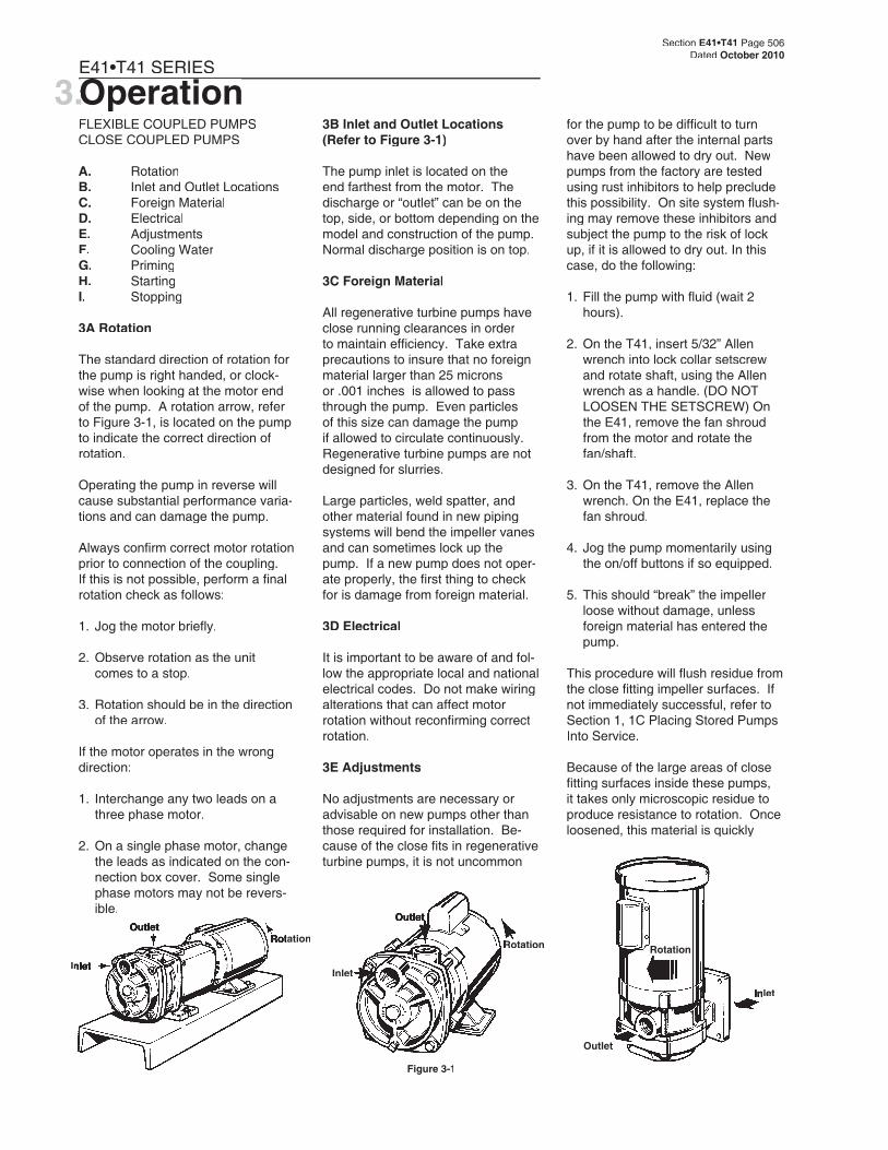
The standard direction of rotation for the pump is right handed, or clock-wise when looking at the motor end of the pump. A rotation arrow, refer to Figure 3-1, is located on the pump to indicate the correct direction of rotation.
Operating the pump in reverse will cause substantial performance varia-tions and can damage the pump.
Always confi rm correct motor rotation prior to connection of the coupling. If this is not possible, perform a fi nal rotation check as follows:
1. Jog the motor briefl y.
2. Observe rotation as the unit comes to a stop.
3. Rotation should be in the direction of the arrow.
If the motor operates in the wrong direction:
1. Interchange any two leads on a three phase motor.
2. On a single phase motor, change the leads as indicated on the con-nection box cover. Some single phase motors may not be revers-ible.
3.OperationOperation3.Operation3.3B Inlet and Outlet Locations (Refer to Figure 3-1)
The pump inlet is located on the end farthest from the motor. The discharge or “outlet” can be on the top, side, or bottom depending on the model and construction of the pump. Normal discharge position is on top.
3C Foreign Material
All regenerative turbine pumps have close running clearances in order to maintain effi ciency. Take extra precautions to insure that no foreign material larger than 25 microns or .001 inches is allowed to pass through the pump. Even particles of this size can damage the pump if allowed to circulate continuously. Regenerative turbine pumps are not designed for slurries.
Large particles, weld spatter, and other material found in new piping systems will bend the impeller vanes and can sometimes lock up the pump. If a new pump does not oper-ate properly, the fi rst thing to check for is damage from foreign material.
3D Electrical
It is important to be aware of and fol-low the appropriate local and national electrical codes. Do not make wiring alterations that can affect motor rotation without reconfi rming correct rotation.
3E Adjustments
No adjustments are necessary or advisable on new pumps other than those required for installation. Be-cause of the close fi ts in regenerative turbine pumps, it is not uncommon
for the pump to be diffi cult to turn over by hand after the internal parts have been allowed to dry out. New pumps from the factory are tested using rust inhibitors to help preclude this possibility. On site system fl ush-ing may remove these inhibitors and subject the pump to the risk of lock up, if it is allowed to dry out. In this case, do the following:
1. Fill the pump with fl uid (wait 2 hours).
2. On the T41, insert 5/32” Allen wrench into lock collar setscrew and rotate shaft, using the Allen wrench as a handle. (DO NOT LOOSEN THE SETSCREW) On the E41, remove the fan shroud from the motor and rotate the fan/shaft.
3. On the T41, remove the Allen wrench. On the E41, replace the fan shroud.
4. Jog the pump momentarily using the on/off buttons if so equipped.
5. This should “break” the impeller loose without damage, unless foreign material has entered the pump.
This procedure will fl ush residue from the close fi tting impeller surfaces. If not immediately successful, refer to Section 1, 1C Placing Stored Pumps Into Service.
Because of the large areas of close fi tting surfaces inside these pumps, it takes only microscopic residue to produce resistance to rotation. Once loosened, this material is quickly
RotationRotationOutlet
InletInletRotation
InletInlet
OutletOutlet
Figure 3-1
Outlet
RotationRotation
Inlet

Section E41•T41 Page 507Dated October 2010
4.ServiceServiceE41•T41 SERIES
PUMP ENDS
A. PreliminaryB. Disassembly C3 & P3(T41)C. Disassembly C15 & P15(T41)D. Disassembly D3 (E41)E. Inspection of ComponentsF. Reassembly C3 & P3(T41)G. Reassembly C15 & P15(T41)H. Reassembly D3 (E41)I. Testing and Final Adjustments
4A Preliminary
Before attempting any service on the pump or motor, disconnect the elec-trical power to the motor. If the pump and motor are to be removed as a unit, note the wiring confi guration.
1. Disconnect the inlet and outlet pip-ing before unbolting the pump and motor.
2. Unbolt the motor from the base and remove the unit. All work on the unit should be performed on an elevated workbench whenever possible.
The disassembly and reassembly procedures are broken into four sec-tions covering the following units:
4B — Disassembly of the C3 and P3 Units (3 hp and under)
4C — Disassembly of the C15 and P15 Units (5 hp and up)
4D — Disassembly of the D3 (E41) Units
4F — Reassembly of the C3 and P3 Units
4G — Reassembly of the C15 and P15 Units
4H — Reassembly of D3 (E41) Units
Exploded views of each unit, Figures 4-4, 4-5, 4-16, and 4-20, are provided for referencing the numbers in the following procedures, i.e. (#1), motor bracket.
4B Disassembly (T41- C3 and P3)
The following tools and equipment are needed for disassembly of C3 and P3 units.
1. Soft plastic or wooden mallet.2. 9/16” wrench or socket.3. 5/32” hex wrench.4. Penetrating oil.5. 1” wood dowel (Approx. 6” long).6. Thin blade screwdriver.7. Two large blade screwdrivers.8. Cealube G or similar glycol base
lubricant. (DO NOT use petroleum products.)
To disassemble the pump:
Refer to Figures 4-4 and 4-5 for refer-ence to the numbered parts in the procedures below.
1. Remove all liquid from the pump. Air blown through the pump will remove the water quickly.
2. Remove the four (4) 3/8” X 4” bolts (#19) from the cover (#2).
3. Remove the cover. In some cases light tapping with a plastic or wooden mallet on the outside diameter of the cover may be required to loosen it from the motor bracket. Care should be taken if a screwdriver is needed to pry between the cover and motor bracket. Damage to the “O” ring (#7) and/or impeller can result.
4. Remove the impeller (#11), refer to Figure 4-1. The impeller is a slip fi t and, under normal condi-tions, can be removed by gently tapping on the end of the shaft sleeve with a mallet. Leave the impeller key (#23) in place. Strik-ing the sleeve too hard could damage the seat or rotating ele-ment.
dispersed and the impellers will fi nd their hydraulic center. If these procedures are followed carefully, no damage will result from “breaking loose” the impeller.
3F Cooling Water
When the pump is used to transfer hot fl uids, consideration should be given to cooling the seals and/or selecting materials that will give satisfactory seal life. The actual tem-perature at the seal faces, the most critical area, will always exceed the surrounding fl uid temperature.
3G Priming
Pumps should not be operated unless they are completely fi lled with liquid. Damage to parts of the pump that depend on liquid for their lubrication can occur. Impellers can
seize quickly when a pump is run dry. Without lubrication, seal faces can be damaged from heat buildup.
3H Starting
Before starting a pump for the fi rst time, be sure that all the preceding operations have been carried out. Proper rotation, priming, and a free turning pump are most important.
1. Start the pump with the minimum possible line restriction.
2. Open discharge valves before pressing the starter.
3. Start the pump and let the system clear of air.
4. Listen for foreign material being carried through the pump.
5. Slowly close necessary valves or otherwise place the pump into service.
6. Listen for indications of undue load or other sounds indicating problems.
7. Use a clip-on ammeter to check for a steady load after ap-proximately fi fteen minutes of operation.
3I Stopping
It is best to stop the pump with the least discharge head possible both for minimizing strain on components, and to be in low power mode in an-ticipation of restarting.
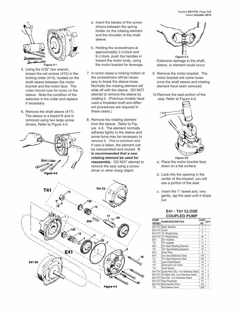
Figure 4-6
E41 - T41 CLOSE COUPLED PUMP
PUMP PUMP SERIESSERIES NAME/DESCRIPTION PART
NO. QTY.
E41/T41E41/T41 Motor Bracket 1 1E41/T41E41/T41 Cover 2 1E41/T41E41/T41 “O” Ring/Casing 7 1E41/T41E41/T41 “O” Ring/Casing“O” Ring/Casing 7A 1E41E41 E41 ImpellerE41 Impeller 11 1T41T41 T41 ImpellerT41 Impeller 11 1E41E41 E41 Seal Rotating Element 12 1T41T41 T41 Seal Rotating ElementT41 Seal Rotating Element 12 1E41E41 Snap RingSnap Ring 4 1E41E41 E41 Seal Stationary Seat 125 1T41T41 T41 Seal Stationary SeatT41 Seal Stationary Seat 125 1T41T41 Lock Collar/Sleeve 14 1T41T41 Setscrew/Lock Collar 15 2T41T41 Shaft Sleeve 17 1E41/T41E41/T41 Guide Rod (Qty. 4 on Stainless Steel)Guide Rod (Qty. 4 on Stainless Steel) 18 0E41/T41E41/T41 ThruBolt (Qty. 0 on Stainless Steel)ThruBolt (Qty. 0 on Stainless Steel) 19 4E41/T41E41/T41 Nut (Qty. 4 on Stainless Steel)Nut (Qty. 4 on Stainless Steel) 20 0E41/T41E41/T41 Pipe Plug/Drain 22 1E41/T41E41/T41 Key/Impeller DriveKey/Impeller Drive 23 1T41T41 Key/Sleeve DriveKey/Sleeve Drive 23A 1
a. Insert the blades of the screw-drivers between the spring holder on the rotating element and the shoulder of the shaft sleeve.
b. Holding the screwdrivers at approximately 3 o’clock and 9 o’clock, push the handles in toward the motor body, using the motor bracket for leverage.
7. In some cases a rocking motion of the screwdrivers will be neces-sary to break the sleeve loose. Normally the rotating element will slide off with the sleeve. DO NOT attempt to remove the sleeve by rotating it. (Previous models have used a threaded shaft and differ-ent procedures are required in these cases.)
8. Remove the rotating element from the sleeve. Refer to Fig-ure 4-3. The element normally adheres tightly to the sleeve and some force may be necessary to remove it. This is common and if care is taken, the element can be reassembled and reused. It is recommended that a new rotating element be used for reassembly. DO NOT attempt to remove the seal using a screw-driver or other sharp object. driver or other sharp object.
Figure 4-1
Figure 4-4
14
125
23A
11
17
12
23
7
T41 C3
1
2
19
15
125
23
12
4
22
T41
E41
E41 D3
Figure 4-3
Section E41•T41 Page 508Dated October 2010
Figure 4-2
Extensive damage to the shaft, sleeve, or element could occur.
9. Remove the motor bracket. The motor bracket will come loose once the shaft sleeve and rotating element have been removed.
10.Remove the seat portion of the seal, Refer to Figure 4-6.
5. Using the 5/32” hex wrench, loosen the set screws (#15) in the locking collar (#14), located on the shaft sleeve between the motor bracket and the motor face. The collar should now be loose on the sleeve. Note the condition of the setscrew in the collar and replace if necessary.
6. Remove the shaft sleeve (#17). The sleeve is a keyed fi t and is removed using two large screw drivers, Refer to Figure 4-2.
a. Place the motor bracket face down on a fl at surface.
b. Look into the opening in the b. Look into the opening in the center of the bracket, you will see a portion of the seat.
c. Insert the 1” dowel and, very c. Insert the 1” dowel and, very gently, tap the seat until it drops out.
7A7A
Section E41•T41 Page 509Dated October 2010
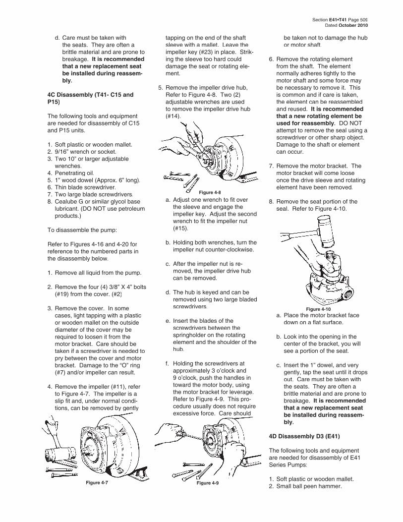
Figure 4-8
Figure 4-7Figure 4-7 Figure 4-9
Figure 4-10
d. Care must be taken with the seats. They are often a brittle material and are prone to breakage. It is recommended that a new replacement seat be installed during reassem-bly.
4C Disassembly (T41- C15 and P15)
The following tools and equipment are needed for disassembly of C15 and P15 units.
1. Soft plastic or wooden mallet.2. 9/16” wrench or socket.3. Two 10” or larger adjustable
wrenches.4. Penetrating oil.5. 1” wood dowel (Approx. 6” long).6. Thin blade screwdriver.7. Two large blade screwdrivers.8. Cealube G or similar glycol base
lubricant. (DO NOT use petroleum products.)
To disassemble the pump:
Refer to Figures 4-16 and 4-20 for reference to the numbered parts in the disassembly below.
1. Remove all liquid from the pump.
2. Remove the four (4) 3/8” X 4” bolts (#19) from the cover. (#2)
3. Remove the cover. In some cases, light tapping with a plastic or wooden mallet on the outside diameter of the cover may be required to loosen it from the motor bracket. Care should be taken if a screwdriver is needed to pry between the cover and motor bracket. Damage to the “O” ring (#7) and/or impeller can result.
4. Remove the impeller (#11), refer to Figure 4-7. The impeller is a slip fi t and, under normal condi-tions, can be removed by gently
tapping on the end of the shaft sleeve with a mallet. Leave the impeller key (#23) in place. Strik-ing the sleeve too hard could damage the seat or rotating ele-ment.
5. Remove the impeller drive hub, Refer to Figure 4-8. Two (2) adjustable wrenches are used to remove the impeller drive hub (#14).
be taken not to damage the hub or motor shaft.
6. Remove the rotating element from the shaft. The element normally adheres tightly to the motor shaft and some force may be necessary to remove it. This is common and if care is taken, the element can be reassembled and reused. It is recommended that a new rotating element be used for reassembly. DO NOT attempt to remove the seal using a screwdriver or other sharp object. Damage to the shaft or element can occur.
7. Remove the motor bracket. The motor bracket will come loose once the drive sleeve and rotating element have been removed.
8. Remove the seat portion of the seal. Refer to Figure 4-10.
a. Adjust one wrench to fi t over the sleeve and engage the impeller key. Adjust the second wrench to fi t the impeller nut (#15).
b. Holding both wrenches, turn the impeller nut counter-clockwise.
c. After the impeller nut is re-moved, the impeller drive hub can be removed.
d. The hub is keyed and can be removed using two large bladed screwdrivers.
e. Insert the blades of the screwdrivers between the springholder on the rotating element and the shoulder of the hub.
f. Holding the screwdrivers at approximately 3 o’clock and 9 o’clock, push the handles in toward the motor body, using the motor bracket for leverage. Refer to Figure 4-9. This pro-cedure usually does not require excessive force. Care should
a. Place the motor bracket face down on a fl at surface.
b. Look into the opening in the center of the bracket, you will see a portion of the seat.
c. Insert the 1” dowel, and very gently, tap the seat until it drops out. Care must be taken with the seats. They are often a brittle material and are prone to breakage. It is recommended that a new replacement seat be installed during reassem-bly.
4D Disassembly D3 (E41)
The following tools and equipment are needed for disassembly of E41 Series Pumps:
1. Soft plastic or wooden mallet.2. Small ball peen hammer.
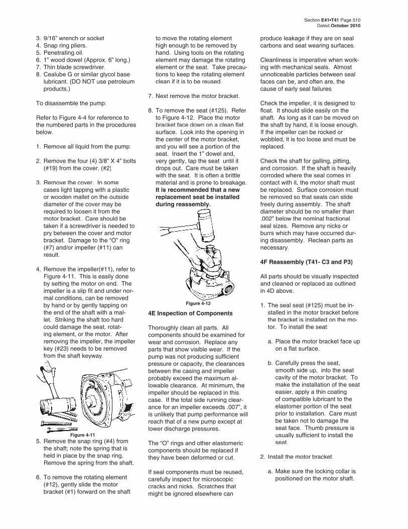
Figure 4-12
Section E41•T41 Page 510Dated October 2010
3. 9/16” wrench or socket4. Snap ring pliers.5. Penetrating oil.6. 1” wood dowel (Approx. 6” long.)7. Thin blade screwdriver.8. Cealube G or similar glycol base
lubricant. (DO NOT use petroleum products.)
To disassemble the pump:
Refer to Figure 4-4 for reference to the numbered parts in the procedures below.
1. Remove all liquid from the pump.
2. Remove the four (4) 3/8” X 4” bolts (#19) from the cover. (#2)
3. Remove the cover. In some cases light tapping with a plastic or wooden mallet on the outside diameter of the cover may be required to loosen it from the motor bracket. Care should be taken if a screwdriver is needed to pry between the cover and motor bracket. Damage to the “O” ring (#7) and/or impeller (#11) can result.
4. Remove the impeller(#11), refer to Figure 4-11. This is easily done by setting the motor on end. The impeller is a slip fi t and under nor-mal conditions, can be removed by hand or by gently tapping on the end of the shaft with a mal-let. Striking the shaft too hard could damage the seat, rotat-ing element, or the motor. After removing the impeller, the impeller key (#23) needs to be removed from the shaft keyway.
to move the rotating element high enough to be removed by hand. Using tools on the rotating element may damage the rotating element or the seat. Take precau-tions to keep the rotating element clean if it is to be reused.
7. Next remove the motor bracket.
8. To remove the seat (#125). Refer to Figure 4-12. Place the motor bracket face down on a clean fl at surface. Look into the opening in the center of the motor bracket, and you will see a portion of the seat. Insert the 1” dowel and, very gently, tap the seat until it drops out. Care must be taken with the seat. It is often a brittle material and is prone to breakage. It is recommended that a new replacement seat be installed during reassembly.
4E Inspection of Components
Thoroughly clean all parts. All components should be examined for wear and corrosion. Replace any parts that show visible wear. If the pump was not producing suffi cient pressure or capacity, the clearances between the casing and impeller probably exceed the maximum al-lowable clearance. At minimum, the impeller should be replaced in this case. If the total side running clear-ance for an impeller exceeds .007”, it is unlikely that pump performance will reach that of a new pump except at lower discharge pressures.
The “O” rings and other elastomeric components should be replaced if they have been deformed or cut.
If seal components must be reused, carefully inspect for microscopic cracks and nicks. Scratches that might be ignored elsewhere can
produce leakage if they are on seal carbons and seat wearing surfaces.
Cleanliness is imperative when work-ing with mechanical seals. Almost unnoticeable particles between seal faces can be, and often are, the cause of early seal failures.
Check the impeller, it is designed to fl oat. It should slide easily on the shaft. As long as it can be moved on the shaft by hand, it is loose enough. If the impeller can be rocked or wobbled, it is too loose and must be replaced.
Check the shaft for galling, pitting, and corrosion. If the shaft is heavily corroded where the seal comes in contact with it, the motor shaft must be replaced. Surface corrosion must be removed so that seals can slide freely during assembly. The shaft diameter should be no smaller than .002” below the nominal fractional seal sizes. Remove any nicks or burrs which may have occurred dur-ing disassembly. Reclean parts as necessary.
4F Reassembly (T41- C3 and P3)
All parts should be visually inspected and cleaned or replaced as outlined in 4D above.
1. The seal seat (#125) must be in-stalled in the motor bracket before the bracket is installed on the mo-tor. To install the seat:
a. Place the motor bracket face up on a fl at surface.
b. Carefully press the seat, smooth side up, into the seat cavity of the motor bracket. To make the installation of the seat easier, apply a thin coating of compatible lubricant to the elastomer portion of the seat prior to installation. Care must be taken not to damage the seat face. Thumb pressure is usually suffi cient to install the seat.
2. Install the motor bracket.
a. Make sure the locking collar is positioned on the motor shaft.
Figure 4-115. Remove the snap ring (#4) from
the shaft; note the spring that is held in place by the snap ring. Remove the spring from the shaft.
6. To remove the rotating element (#12), gently slide the motor bracket (#1) forward on the shaft
Section E41•T41 Page 511Dated October 2010
125
12
23
23A
19
7
11
2
60
1514
1
Figure 4-5
17
T41 C3
125
12
23
11
4
Figure 4-13
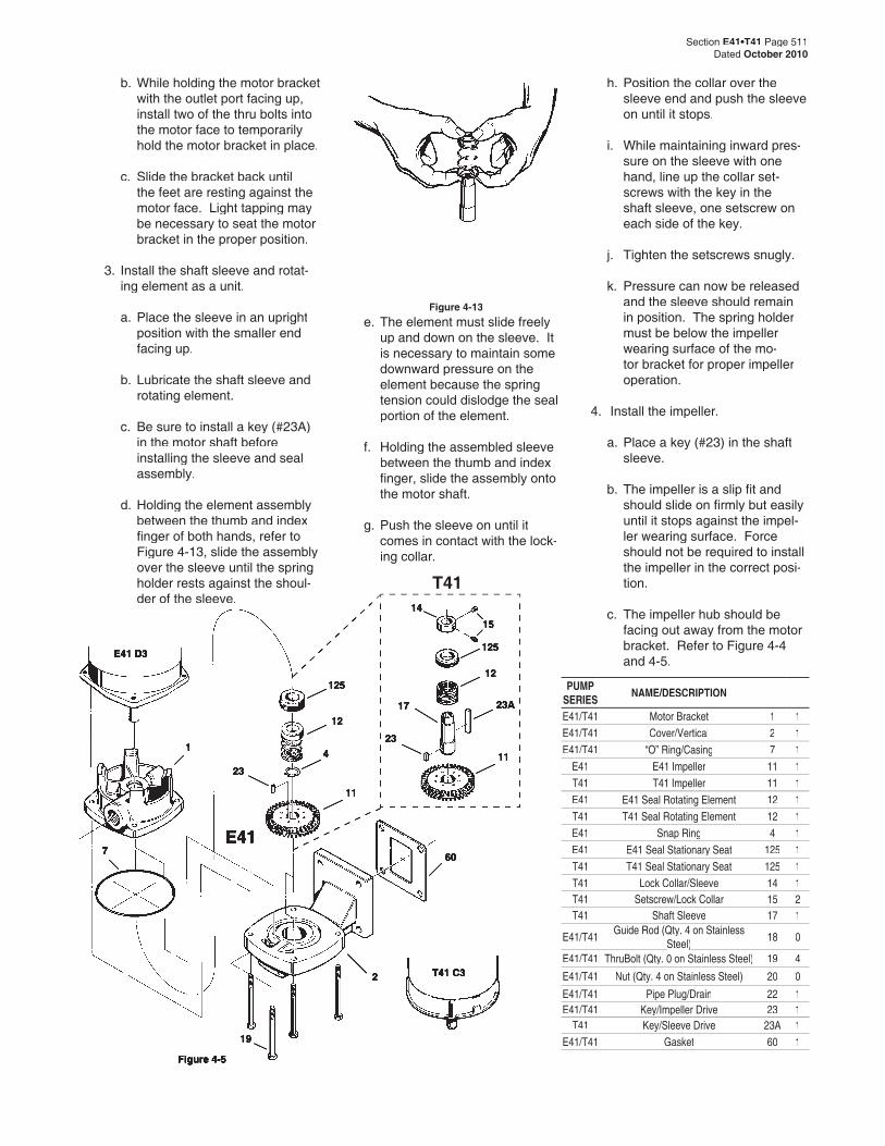
PUMP SERIES NAME/DESCRIPTION
E41/T41 Motor Bracket 1 1E41/T41 Cover/Vertical 2 1E41/T41 “O” Ring/Casing 7 1
E41 E41 Impeller 11 1T41 T41 Impeller 11 1E41 E41 Seal Rotating Element 12 1T41 T41 Seal Rotating Element 12 1E41 Snap Ring 4 1E41 E41 Seal Stationary Seat 125 1T41 T41 Seal Stationary Seat 125 1T41 Lock Collar/Sleeve 14 1T41 Setscrew/Lock Collar 15 2T41 Shaft Sleeve 17 1
E41/T41Guide Rod (Qty. 4 on Stainless
Steel)Steel)18 0
E41/T41 ThruBolt (Qty. 0 on Stainless Steel) 19 4
E41/T41 Nut (Qty. 4 on Stainless Steel) 20 0
E41/T41 Pipe Plug/Drain 22 1E41/T41 Key/Impeller Drive 23 1
T41 Key/Sleeve Drive 23A 1E41/T41 Gasket 60 1
T41
E41
E41 D3
b. While holding the motor bracket with the outlet port facing up, install two of the thru bolts into the motor face to temporarily hold the motor bracket in place.
c. Slide the bracket back until the feet are resting against the motor face. Light tapping may be necessary to seat the motor bracket in the proper position.
3. Install the shaft sleeve and rotat-ing element as a unit.
a. Place the sleeve in an upright position with the smaller end facing up.
b. Lubricate the shaft sleeve and rotating element.
c. Be sure to install a key (#23A) in the motor shaft before installing the sleeve and seal assembly.
d. Holding the element assembly between the thumb and index fi nger of both hands, refer to Figure 4-13, slide the assembly over the sleeve until the spring holder rests against the shoul-der of the sleeve.
e. The element must slide freely up and down on the sleeve. It is necessary to maintain some downward pressure on the element because the spring tension could dislodge the seal portion of the element.
f. Holding the assembled sleeve between the thumb and index fi nger, slide the assembly onto the motor shaft.
g. Push the sleeve on until it comes in contact with the lock-ing collar.
h. Position the collar over the sleeve end and push the sleeve on until it stops.
i. While maintaining inward pres-sure on the sleeve with one hand, line up the collar set-screws with the key in the shaft sleeve, one setscrew on each side of the key.
j. Tighten the setscrews snugly.
k. Pressure can now be released and the sleeve should remain in position. The spring holder must be below the impeller wearing surface of the mo-tor bracket for proper impeller operation.
4. Install the impeller.
a. Place a key (#23) in the shaft sleeve.
b. The impeller is a slip fi t and should slide on fi rmly but easily until it stops against the impel-ler wearing surface. Force should not be required to install the impeller in the correct posi-tion.
c. The impeller hub should be facing out away from the motor bracket. Refer to Figure 4-4 and 4-5.
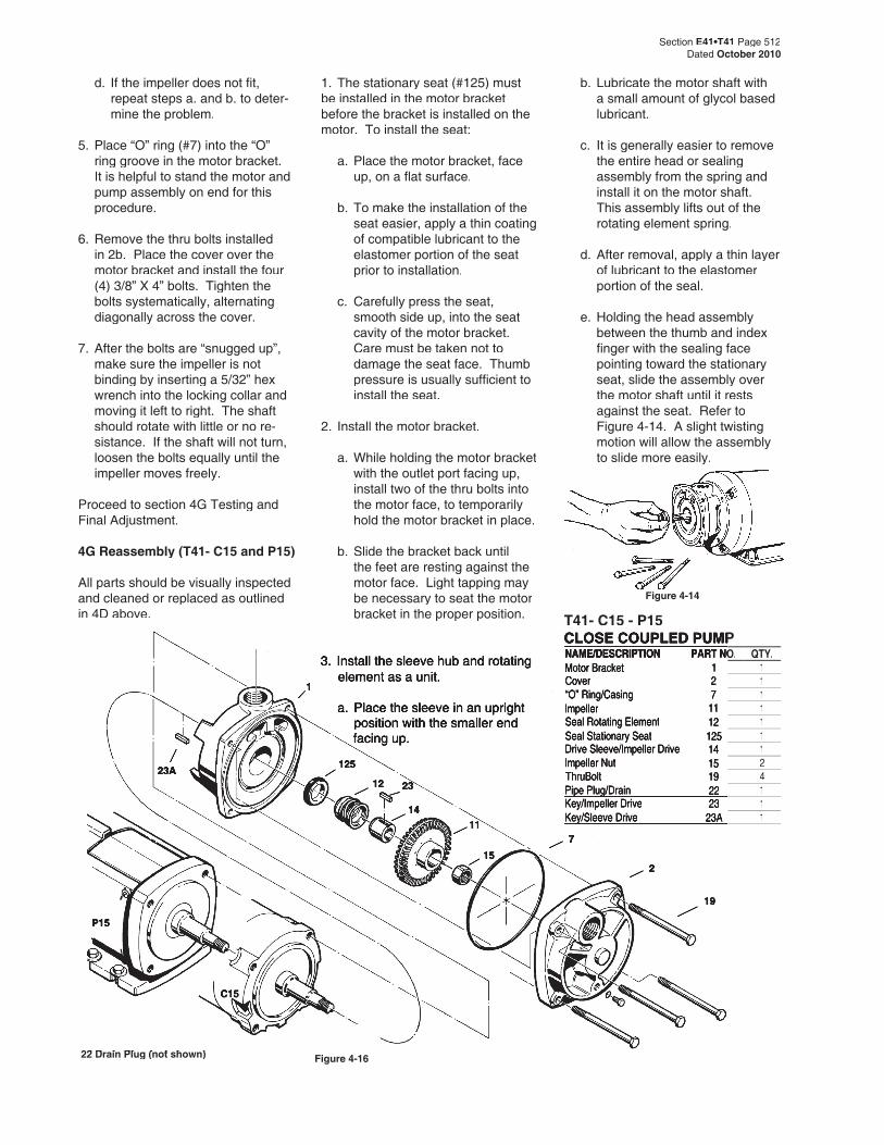
Figure 4-14
T41- C15 - P15T41- C15 - P15CLOSE COUPLED PUMPCLOSE COUPLED PUMP
Figure 4-16
C15
P15
1
23A 125
23
1411
7
2
12
19
15
22 Drain Plug (not shown)22 Drain Plug (not shown)
NAME/DESCRIPTION PART NO.PART NO. QTY.Motor Bracket 1 1Cover 2 1“O” Ring/Casing“O” Ring/Casing 7 1Impeller 11 1Seal Rotating ElementSeal Rotating Element 12 1Seal Stationary Seat 125 1Drive Sleeve/Impeller Drive 14 1Impeller Nut 15 2ThruBolt 19 4Pipe Plug/DrainPipe Plug/Drain 22 1Key/Impeller Drive 23 1Key/Sleeve Drive 23A 1
Section E41•T41 Page 512Dated October 2010
d. If the impeller does not fi t, repeat steps a. and b. to deter-mine the problem.
5. Place “O” ring (#7) into the “O” ring groove in the motor bracket. It is helpful to stand the motor and pump assembly on end for this procedure.
6. Remove the thru bolts installed in 2b. Place the cover over the motor bracket and install the four (4) 3/8” X 4” bolts. Tighten the bolts systematically, alternating diagonally across the cover.
7. After the bolts are “snugged up”, make sure the impeller is not binding by inserting a 5/32” hex wrench into the locking collar and moving it left to right. The shaft should rotate with little or no re-sistance. If the shaft will not turn, loosen the bolts equally until the impeller moves freely.
Proceed to section 4G Testing and Final Adjustment.
4G Reassembly (T41- C15 and P15)
All parts should be visually inspected and cleaned or replaced as outlined in 4D above.
1. The stationary seat (#125) must be installed in the motor bracket before the bracket is installed on the motor. To install the seat:
a. Place the motor bracket, face up, on a fl at surface.
b. To make the installation of the seat easier, apply a thin coating of compatible lubricant to the elastomer portion of the seat prior to installation.
c. Carefully press the seat, smooth side up, into the seat cavity of the motor bracket. Care must be taken not to damage the seat face. Thumb pressure is usually suffi cient to install the seat.
2. Install the motor bracket.
a. While holding the motor bracket with the outlet port facing up, install two of the thru bolts into the motor face, to temporarily hold the motor bracket in place.
b. Slide the bracket back until the feet are resting against the motor face. Light tapping may be necessary to seat the motor bracket in the proper position.
3. Install the sleeve hub and rotating element as a unit.
a. Place the sleeve in an upright position with the smaller end facing up.
b. Lubricate the motor shaft with a small amount of glycol based lubricant.
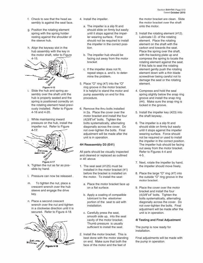
c. It is generally easier to remove the entire head or sealing assembly from the spring and install it on the motor shaft. This assembly lifts out of the rotating element spring.
d. After removal, apply a thin layer of lubricant to the elastomer portion of the seal.
e. Holding the head assembly between the thumb and index fi nger with the sealing face pointing toward the stationary seat, slide the assembly over the motor shaft until it rests against the seat. Refer to Figure 4-14. A slight twisting motion will allow the assembly to slide more easily.
Section E41•T41 Page 513Dated October 2010
Figure 4-17
Figure 4-18
f. Check to see that the head as-sembly is against the seat face.
g. Position the rotating element spring with the spring holder resting against the shoulder of the sleeve hub.
h. Align the keyway slot in the hub assembly with the key in the motor shaft, refer to Figure 4-15.
i. Slide the hub and spring as-sembly over the shaft until the hub is properly seated and the spring is positioned correctly on the rotating element head previ-ously installed. Refer to Figure 4-16 and 4-20.
j. While maintaining inward pressure on the hub, install the impeller nut. Refer to Figure 4-17.4-17.
4. Install the impeller.
a. The impeller is a slip fi t and should slide on fi rmly but easily until it stops against the impel-ler wearing surface. Force should not be required to install the impeller in the correct posi-tion.
b. The impeller hub should be facing out away from the motor bracket.
c. If the impeller does not fi t, repeat steps a. and b. to deter-mine the problem.
5. Place “O” ring (#7) into the “O” ring groove in the motor bracket. It is helpful to stand the motor and pump assembly on end for this procedure.
6. Remove the thru bolts installed in 2a. Place the cover over the motor bracket and install the four (4)3/8”x4” bolts. Tighten the bolts systematically, alternating diagonally across the cover. Do not over-tighten the bolts. Final adjustment will be made after the unit is in operation.
4H Reassembly D3 (E41)
All parts should be visually inspected and cleaned or replaced as outlined in 4E above.
1. The seal seat (#125) must be installed in the motor bracket (#1) before the bracket is installed on the motor. To install the seat:
a. Place the motor bracket face up on a fl at surface.
b. Apply a coating of compatible lubricant to the elastomer portion of the seat to aid with installation.
c. Carefully press the seat, smooth side up, into the seat cavity of the motor bracket. Thumb pressure is usually suffi cient to install the seat.
2. Install the motor bracket. This is best done with the motor standing on end. Make sure that both the face of the motor and the feet of
the motor bracket are clean. Slide the motor bracket over the shaft onto the motor.
3. Install the rotating element (#12). Lubricate I.D. of the rotating element. Place the rotating element on the shaft with the carbon end towards the seat. Place the spring over the shaft, with the backing plate up and compress the spring to locate the rotating element against the seat. If this fails to seat the rotating element gently push the rotating element down with a thin blade screwdriver being careful not to damage the seat or the rotating element.
4. Compress and hold the seal spring slightly below the snap ring groove and install the snap ring (#4). Make sure the snap ring is locked in the groove.
5. Install the impeller key (#23) into the shaft keyway.
6. The impeller is a slip fi t and should slide on fi rmly but easily until it stops against the impeller wearing surface. Force should not be required or used to install the impeller in the correct position. The impeller hub should be facing out away from the motor bracket. Refer to Figures 4-4 and
4-5.
7. Next, rotate the impeller by hand, the impeller should move freely.
8. Place the large “O” ring (#7) into the outside “O” ring groove in the motor bracket.
9. Place the cover over the motor bracket and install the four
(4)3/8”x4” bolts. Tighten the bolts systematically, alternating diagonally across the cover. Do not over-tighten the bolts. Final adjustment will be made after the unit is in operation.
4I Testing and Final Adjustment
The pump is now ready for installation.
Final adjustments will be made with the pump in operation.
Figure 4-15
k. Tighten the nut as far as pos-sible by hand.
l. Pressure can now be released .
m. To tighten the nut, place a crescent wrench over the hub sleeve and engage the drive key.
n. Place a second crescent wrench over the nut and tighten in a clockwise direction until it is secured. Refer to Figure 4-18.
Section E41•T41 Page 514Dated October 2010
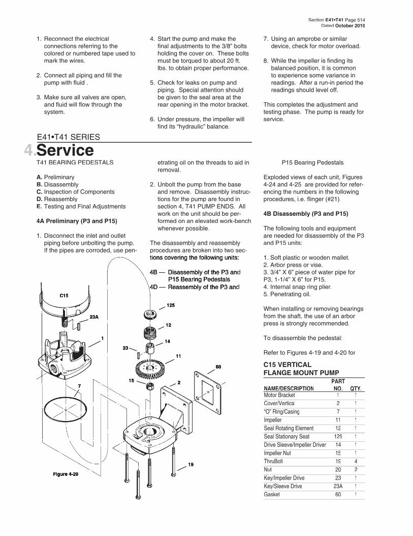
C15 VERTICALFLANGE MOUNT PUMP
Figure 4-20
125
12
14
11
15
23
60
19
27
1
23A
C15
4.ServiceE41•T41 SERIES
T41 BEARING PEDESTALS
A. PreliminaryB. DisassemblyC. Inspection of ComponentsD. ReassemblyE. Testing and Final Adjustments
4A Preliminary (P3 and P15)
1. Disconnect the inlet and outlet piping before unbolting the pump. If the pipes are corroded, use pen-
etrating oil on the threads to aid in removal.
2. Unbolt the pump from the base and remove. Disassembly instruc-tions for the pump are found in section 4, T41 PUMP ENDS. All work on the unit should be per-formed on an elevated work-bench whenever possible.
The disassembly and reassembly procedures are broken into two sec-tions covering the following units:tions covering the following units:
4B — Disassembly of the P3 and 4B — Disassembly of the P3 and P15 Bearing Pedestals
4D — Reassembly of the P3 and 4D — Reassembly of the P3 and
P15 Bearing Pedestals
Exploded views of each unit, Figures 4-24 and 4-25 are provided for refer-encing the numbers in the following procedures, i.e. fl inger (#21).
4B Disassembly (P3 and P15)
The following tools and equipment are needed for disassembly of the P3 and P15 units:
1. Soft plastic or wooden mallet.2. Arbor press or vise.3. 3/4” X 6” piece of water pipe for P3, 1-1/4” X 6” for P15.4. Internal snap ring plier.5. Penetrating oil.
When installing or removing bearings from the shaft, the use of an arbor press is strongly recommended.
To disassemble the pedestal:
Refer to Figures 4-19 and 4-20 for
NAME/DESCRIPTIONPART NO. QTY.
Motor Bracket 1 1Cover/Vertical 2 1“O” Ring/Casing 7 1Impeller 11 1Seal Rotating Element 12 1Seal Stationary Seat 125 1Drive Sleeve/Impeller Driver 14 1Impeller Nut 15 1ThruBolt 19 4Nut 20 2Key/Impeller Drive 23 1Key/Sleeve Drive 23A 1Gasket 60 1
1. Reconnect the electrical connections referring to the colored or numbered tape used to mark the wires.
2. Connect all piping and fi ll the pump with fl uid .
3. Make sure all valves are open, and fl uid will fl ow through the system.
4. Start the pump and make the fi nal adjustments to the 3/8” bolts holding the cover on. These bolts must be torqued to about 20 ft. lbs. to obtain proper performance.
5. Check for leaks on pump and piping. Special attention should be given to the seal area at the rear opening in the motor bracket.
6. Under pressure, the impeller will fi nd its “hydraulic” balance.
7. Using an amprobe or similar device, check for motor overload.
8. While the impeller is fi nding its balanced position, it is common to experience some variance in readings. After a run-in period the readings should level off.
This completes the adjustment and testing phase. The pump is ready for service.
3. Repeat step 2 to remove the other bearing. Good support used on the inner races will prevent bear-ing damage.
4C Inspection of Components
Thoroughly clean all parts. All com-ponents should be examined for wear and corrosion. Replace any parts showing visible wear.
Check to be certain that a press fi t still exists between the shaft and the bearings. New bearingsNew bearings, or at least cleaned and regreased bearings, are recommended.
Check the shaft for galling, pitting, and corrosion. Surface corrosion on the pump portion of the shaft must be removed so the seals will slide freely during assembly. The shaft diameter should be no smaller than .002” be-low the nominal fractional seal sizes. Remove any nicks or burrs which may have occurred during disassem-bly. Reclean parts as necessary.
4D Reassembly
All parts should be visually inspected and cleaned or replaced as outlined in 4C above. It is recommended that the bearings be replaced any time the bearing pedestal is disassembled for service.
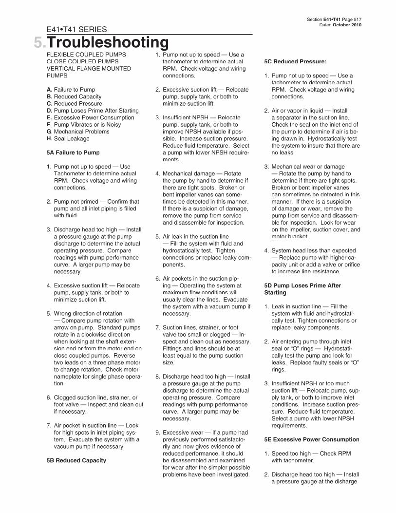
1. Using an arbor press, install the bearings on the shaft prior to in-stalling the shaft into the pedestal. A steel “donut” with the proper inside diameter and outside diam-eter, refer to Chart 1, should be used between the arbor face plate and the lower bearing to insure proper installation, and to prevent bearing damage. The bearings
Section E41•T41 Page 515Dated October 2010
reference to the numbered parts in the procedures below.
1. Remove the fl inger (#21) located on the pump end of the bearing pedestal (#3).
2. Using a snap ring plier, remove snap ring (#4).
3. Open the jaws of the vice approxi-mately 2-1/4” for model P3 and 3” for model P15.
4. Place the pedestal, pump side down, on the jaws. Refer to Figure 4-19.
5. Using a plastic or wooden mallet, gently tap on the end of the shaft until it slides out of the frame. Both bearings should come out with the shaft. Do not use a metal
hammer, severe damage to the shaft will occur.
6. Using the arbor press, remove the two (2) bearings from the shaft. Refer to Figure 4-21. If the inner race is well supported during this operation, no damage will be done to the bearings.
30 23
17
244
21213
33
24A
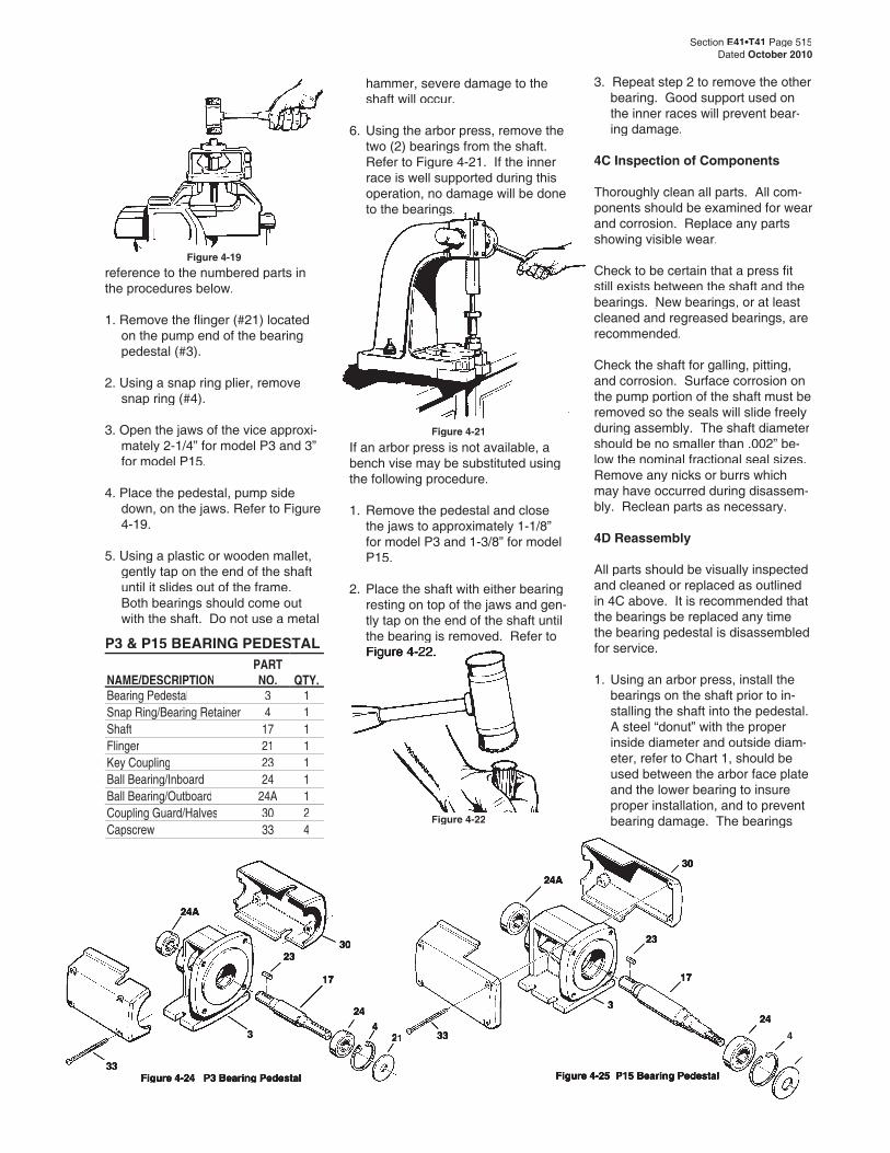
Figure 4-24 P3 Bearing PedestalFigure 4-24 P3 Bearing Pedestal
4
P3 & P15 BEARING PEDESTAL
Figure 4-21
Figure 4-22
If an arbor press is not available, a bench vise may be substituted using the following procedure.
1. Remove the pedestal and close the jaws to approximately 1-1/8” for model P3 and 1-3/8” for model P15.
2. Place the shaft with either bearing resting on top of the jaws and gen-tly tap on the end of the shaft until the bearing is removed. Refer to Figure 4-22.Figure 4-22.
30
23
17
24 33
24A
3
Figure 4-25 P15 Bearing Pedestal
NAME/DESCRIPTIONPART NO. QTY.
Bearing Pedestal 3 1Snap Ring/Bearing Retainer 4 1Shaft 17 1Flinger 21 1Key Coupling 23 1Ball Bearing/Inboard 24 1Ball Bearing/Outboard 24A 1Coupling Guard/Halves 30 2Capscrew 33 4
Figure 4-19
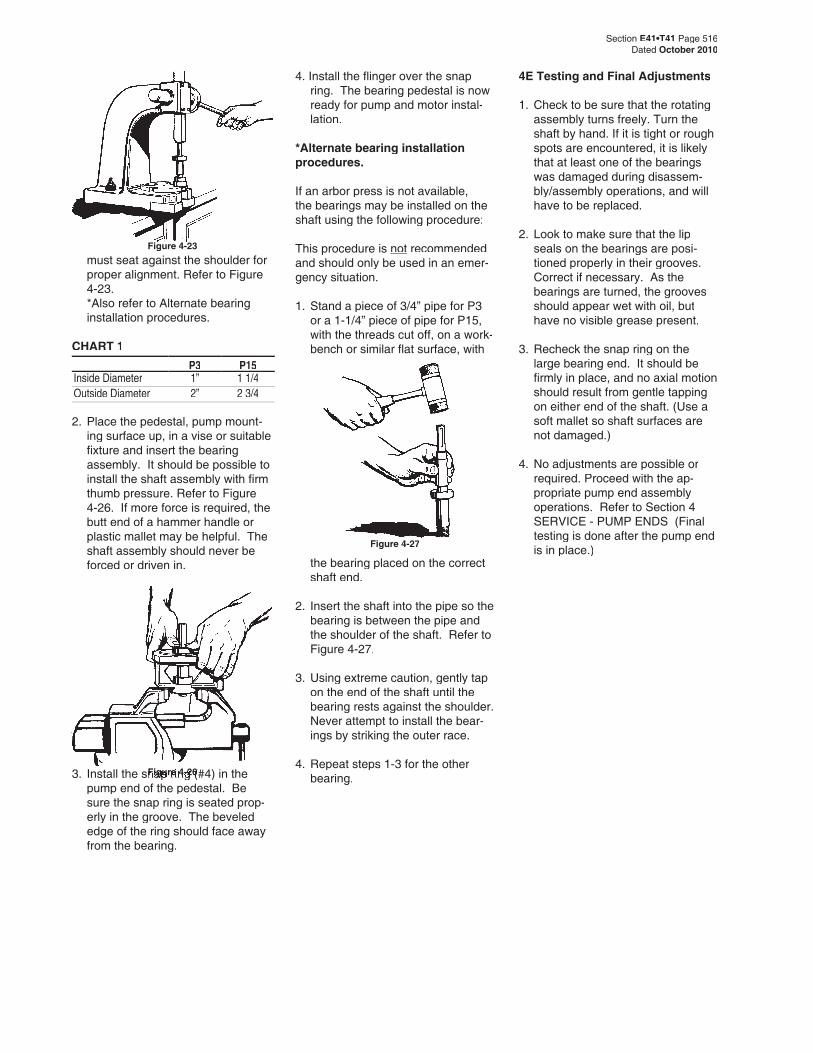
Figure 4-26
Section E41•T41 Page 516Dated October 2010
must seat against the shoulder for proper alignment. Refer to Figure 4-23.
*Also refer to Alternate bearing installation procedures.
CHART 1P3 P15
Inside Diameter 1” 1 1/4Outside Diameter 2” 2 3/4
2. Place the pedestal, pump mount-ing surface up, in a vise or suitable fi xture and insert the bearing assembly. It should be possible to install the shaft assembly with fi rm thumb pressure. Refer to Figure
4-26. If more force is required, the butt end of a hammer handle or plastic mallet may be helpful. The shaft assembly should never be forced or driven in.
4. Install the fl inger over the snap ring. The bearing pedestal is now ready for pump and motor instal-lation.
*Alternate bearing installation procedures.
If an arbor press is not available, the bearings may be installed on the shaft using the following procedure:
This procedure is not recommended and should only be used in an emer-gency situation.
1. Stand a piece of 3/4” pipe for P3 or a 1-1/4” piece of pipe for P15, with the threads cut off, on a work-bench or similar fl at surface, with
4E Testing and Final Adjustments
1. Check to be sure that the rotating assembly turns freely. Turn the shaft by hand. If it is tight or rough spots are encountered, it is likely that at least one of the bearings was damaged during disassem-bly/assembly operations, and will have to be replaced.
2. Look to make sure that the lip seals on the bearings are posi-tioned properly in their grooves. Correct if necessary. As the bearings are turned, the grooves should appear wet with oil, but have no visible grease present.
3. Recheck the snap ring on the large bearing end. It should be fi rmly in place, and no axial motion should result from gentle tapping on either end of the shaft. (Use a soft mallet so shaft surfaces are not damaged.)
4. No adjustments are possible or required. Proceed with the ap-propriate pump end assembly operations. Refer to Section 4 SERVICE - PUMP ENDS (Final testing is done after the pump end is in place.)Figure 4-27
the bearing placed on the correct shaft end.
2. Insert the shaft into the pipe so the bearing is between the pipe and the shoulder of the shaft. Refer to Figure 4-27.
3. Using extreme caution, gently tap on the end of the shaft until the bearing rests against the shoulder. Never attempt to install the bear-ings by striking the outer race.
4. Repeat steps 1-3 for the other bearing.
Figure 4-23
3. Install the snap ring (#4) in the Figure 4-263. Install the snap ring (#4) in the Figure 4-26
pump end of the pedestal. Be sure the snap ring is seated prop-erly in the groove. The beveled edge of the ring should face away from the bearing.
Section E41•T41 Page 517Dated October 2010
FLEXIBLE COUPLED PUMPSCLOSE COUPLED PUMPSVERTICAL FLANGE MOUNTED PUMPS
A. Failure to PumpB. Reduced CapacityC. Reduced PressureD. Pump Loses Prime After StartingE. Excessive Power ConsumptionF. Pump Vibrates or is NoisyG. Mechanical ProblemsH. Seal Leakage
5A Failure to Pump
1. Pump not up to speed — Use Tachometer to determine actual RPM. Check voltage and wiring connections.
2. Pump not primed — Confi rm that pump and all inlet piping is fi lled with fl uid.
3. Discharge head too high — Install a pressure gauge at the pump discharge to determine the actual operating pressure. Compare readings with pump performance curve. A larger pump may be necessary.
4. Excessive suction lift — Relocate pump, supply tank, or both to minimize suction lift.
5. Wrong direction of rotation — Compare pump rotation with arrow on pump. Standard pumps rotate in a clockwise direction when looking at the shaft exten-sion end or from the motor end on close coupled pumps. Reverse two leads on a three phase motor to change rotation. Check motor nameplate for single phase opera-tion.
6. Clogged suction line, strainer, or foot valve — Inspect and clean out if necessary.
7. Air pocket in suction line — Look for high spots in inlet piping sys-tem. Evacuate the system with a vacuum pump if necessary.
5B Reduced Capacity
1. Pump not up to speed — Use a tachometer to determine actual RPM. Check voltage and wiring connections.
2. Excessive suction lift — Relocate pump, supply tank, or both to minimize suction lift.
3. Insuffi cient NPSH — Relocate pump, supply tank, or both to improve NPSH available if pos-sible. Increase suction pressure. Reduce fl uid temperature. Select a pump with lower NPSH require-ments.
4. Mechanical damage — Rotate the pump by hand to determine if there are tight spots. Broken or bent impeller vanes can some-times be detected in this manner. If there is a suspicion of damage, remove the pump from service and disassemble for inspection.
5. Air leak in the suction line — Fill the system with fl uid and hydrostatically test. Tighten connections or replace leaky com-ponents.
6. Air pockets in the suction pip-ing — Operating the system at maximum fl ow conditions will usually clear the lines. Evacuate the system with a vacuum pump if necessary.
7. Suction lines, strainer, or foot valve too small or clogged — In-spect and clean out as necessary. Fittings and lines should be at least equal to the pump suction size.
8. Discharge head too high — Install a pressure gauge at the pump discharge to determine the actual operating pressure. Compare readings with pump performance curve. A larger pump may be necessary.
9. Excessive wear — If a pump had previously performed satisfacto-rily and now gives evidence of reduced performance, it should be disassembled and examined for wear after the simpler possible problems have been investigated.
5C Reduced Pressure:
1. Pump not up to speed — Use a tachometer to determine actual RPM. Check voltage and wiring connections.
2. Air or vapor in liquid — Install a separator in the suction line. Check the seal on the inlet end of the pump to determine if air is be-ing drawn in. Hydrostatically test the system to insure that there are no leaks.
3. Mechanical wear or damage — Rotate the pump by hand to determine if there are tight spots. Broken or bent impeller vanes can sometimes be detected in this manner. If there is a suspicion of damage or wear, remove the pump from service and disassem-ble for inspection. Look for wear on the impeller, suction cover, and motor bracket.
4. System head less than expected — Replace pump with higher ca-pacity unit or add a valve or orifi ce to increase line resistance.
5D Pump Loses Prime After Starting
1. Leak in suction line — Fill the system with fl uid and hydrostati-cally test. Tighten connections or replace leaky components.
2. Air entering pump through inlet seal or “O” rings — Hydrostati-cally test the pump and look for leaks. Replace faulty seals or “O” rings.
3. Insuffi cient NPSH or too much suction lift — Relocate pump, sup-ply tank, or both to improve inlet conditions. Increase suction pres-sure. Reduce fl uid temperature. Select a pump with lower NPSH requirements.
5E Excessive Power Consumption
1. Speed too high — Check RPM with tachometer.
2. Discharge head too high — Install a pressure gauge at the disharge
5.E41•T41 SERIES
Troubleshooting
to determine the actual operat-ing pressure. Compare readings with pump performance curve. A different pump, motor, or both may be necessary.
3. Specifi c gravity or viscosity too high — Check fl uid involved. A different motor may be necessary.
4. Mechanical damage — Turn pump over by hand. After a few days run-in period, all models should turn over by hand with no tight spots. An exception to this is when the pump has been idle for some time. In this case, run the pump for a few hours before checking for tight spots. If there is a suspicion of damage, remove the pump from service and disas-semble for inspection.
5. Pump not fully “broken in” — It is normal for new pumps to consume higher than normal current during the break-in period. If high power consumption persists beyond a few weeks, it is unlikely that further operation will reduce consumption.
6. Pump not properly adjusted — Loosen all nuts on pump exactlyexactlyone turn. Follow the instructions in Section 4F Testing and Final Adjustments, for repositioning fasteners.
5F Pump Vibrates Or Is Noisy
1. Pump and motor are misaligned — Follow the instructions in Section 2D Alignment, for proper alignment.
2. Insecure mounting — Follow instructions in Section 2, 2B Foun-dation.
3. Piping load on pump — Install pip-ing supports and check to see that there is no strain on the pump.
4. Mechanical damage — If me-chanical damage is suspected,
check fi rst to determine if the pump turns freely. Disassemble for inspection if tight spots are found.
5. Pump has a high pitched whine — This is typical of a regenera-tive turbine pump. The intensity should increase as pressure in-creases. Over a period of a few weeks the noise level will diminish and will be noticeably quieter as it approaches a “run-in” condition.
5G Mechanical Problems
1. Short bearing life — Bearings damaged due to leaky seals. Coupling misalignment. Piping load on pump. RPM or pump pressure too high.
2. Pump locked up — Pump dried out and close clearance areas rusted. Follow installation instruc-tions for loosening the pump. Foreign material in pump. Flush out. Disassemble if fl ushing is not successful.
3. Pump leaks — Seal or “O” rings are usually the problem. Disas-sembly and replacement is the solution if tightening the thru bolts has no effect.
5H Seal Leakage
1. Worn seat or rotating element — Seals will last many years oper-ating on cold clear water or other fl uids with reasonable lubric-ity. Particles, even microscopic, increase normal wear rates. Tem-peratures near the fl uid’s boiling point can reduce lubricity which in turn increases wear. Some chemicals will erode the seal faces or plate out on the faces produc-ing an abrasive effect. Immediate seal replacement is recommended when leaks become evident, since bearings are quickly ruined when exposed to moisture. Severe mechanical damage results when the bearings fail.
2. Improperly installed seat or rotating element — If a seal has
recently been replaced, look for a missing “O” ring/cup around the seat, or a seat that was installed cocked or backwards. The smooth surface should face the rotating element. The rotat-ing element may be in backward or improperly positioned. Refer to the appropriate seal diagrams and instructions to confi rm the correct seal orientation. Rotat-ing elements sometimes stick in the wrong position if left partially assembled for some time. Make sure a rotating element can be moved axially on the shaft before closing up the pump, and then make the fi nal adjustments as soon as possible.
3. Seat broken during assembly — Ceramic seats are particularly vulnerable to damage. Carefully follow reassembly instructions for seals. Seals on fl ex-coupled units can be damaged by excessive hammering when installing the coupling onto the shaft extension.
4. Pitted shaft under the seal — Re-using a shaft or sleeve when repairing a pump is the probable cause of this problem. The seal rotating element can produce a pitted surface underneath its elas-tomer portion during normal use. This is normally not a problem for the fi rst seal assembly since the elastomer is conforming as this action occurs. A new seal can leak before it conforms if the pits are large enough. If any pits are visible to the unaided eye, shaft or sleeve replacement is advised.
Section E41•T41 Page 517Dated October 2010
Section E41•T41 Page 518Dated October 2010
7.Limited WarrantyE41•T41 SERIES
A. PartsB. Repair ServiceC. Warranty ServiceD. Motors, Mechanical Seals, and Accessories
6A Parts
Repair parts may be obtained through your local Authorized MTH Pumps Representative or Distributor who can be found in the yellow pages or by contacting MTH Pumps at: 401 W. Main St. • Plano, IL 60545 Phone: 630-552-4115Fax: 630-552-3688
6B Repair Services
Repair service for an MTH pump should be obtained from the compa-ny through which it was purchased.
6.In the event this is not possible, the name and phone number of a nearby MTH representative or distributor may be obtained by contacting MTH Pumps. In the event that it is neces-sary to return the pump to the factory for repairs, remove all accessories attached to the pump. We cannot accept responsibility for their safe removal, storage, and return.
6C Warranty Service
All requests for warranty claims should be made through the com-pany from which the pump was purchased or supplied. Complete details on what is wrong with the pump must be provided along with information on the system in which it is installed. Refer to the MTH Pumps Limited Warranty statement. Return authorization must be obtained prior authorization must be obtained prior to returning any equipment.to returning any equipment.
6D Motors, Mechanical Seals, and Accessories
Repair or replacement service on motors, mechanical seals, relief valves, or other accessories should be obtained from the manufacturer of these components. MTH does not carry replacement parts and is not authorized to render repair service on these components. Replace-ment mechanical seals are stocked at MTH and are always available insofar as possible for immediate shipment. Warranty service, as well as expert application information can be obtained from your local seal manufacturer’s sales offi ce.
Parts and Repair ServicesE41•T41 SERIES
All requests for warranty claims should be made through the com-pany from which the product was purchased or supplied. Complete details on what is wrong with the product must be provided along with information on the system in which it is installed. Refer to the MTH Pumps Limited Warranty statement below for more information. Return authorization must be obtained prior to returning any equipment.
MTH Tool Company, Inc. / MTH Pumps, hereinafter referred to as “MTH”, warrants for a period of twelve (12) months from the date of shipment (“The Warranty Period”), that the products manufactured by it will be free from defects in material and workmanship. MTH will correct defects in material or workmanship which may develop in its products under proper or normal use during the Warranty Period and under the conditions of this Warranty. This Warranty does not extend to anyone except the original consumer-pur-chaser. Damage to the product due to improper handling, improper storage, improper maintenance, or improper application is not covered
by this Warranty. Warranty claims for special order items or accessories not manufactured by MTH (such as motors, valves, or mechanical seals) should be directed to those who manufactured the item. MTH will repair or replace, at its option and expense, its products proved to be defective after examination by an au-thorized representative of MTH. The defective Product must be returned, transportation prepaid, to the factory at Plano, Illinois, USA. Disassembly of the product (especially pumps) impairs determination of reasons for failure and shall be cause for voiding this Warranty. The Product, repaired or replaced, will be shipped F.O.B. MTH’s factory. This is MTH’s sole warranty. MTH makes no other warranty of any kind, express or implied, and all implied warranties of merchantability and fi tness for a particular purpose which exceed MTH’s aforestated obligations are hereby disclaimed by MTH and excluded from this warranty. MTH neither assumes nor authorizes any person to assume for it, any other ob-ligation in connection with the sale of the Product and any enlargement of
this Warranty by a purchaser shall be for its own account and its exclusive responsibility. This Warranty shall not apply to any Product or parts of Products which: (a) have been re-paired, assembled, or altered outside of MTH’s factory, in any manner; or (b) have been subjected to misuse, negligence or accident; or (c) have been used in a manner inconsistent with MTH’s printed instructions, specifi cations, or the customer sup-plied application specifi cation; or (d) have been damaged due to defective power supply or faulty installation. MTH shall not be liable for inci-dental and consequential losses and damages under this express warranty, any applicable implied warranty, or claims for negligence, except to the extent that this limi-tation is found to be unenforceable under the applicable State law. Some States do not allow the ex-clusion or limitation of incidental or consequential damages, so the above limitation or exclusion may not apply to you. This warranty gives you specifi c legal rights, and you may also have other rights, which vary from State to State.

Section E41•T41 Page 519Dated October 2010
97-4622-01-588