Hopper Discharge Devices - Otto von Guericke University ... · 4.5 Agitator, Stirrer 4.6 Rotary...
11
1.1 Belt conveyor 1.2 Apron belt conveyor 1.3 Belt balance for dosing 4.1 Screw feeder 4.2 Rotary feeder , star feeder 4.3 Rotary scraper 4.4 Table, Disk, Roller feeder 4.5 Agitator, Stirrer 4.6 Rotary plough, arms, beams 2.1 Sceleton flight conveyor 2.2 Chain feeder Hopper Discharge Devices with traction without traction 1. Belt feeder 2. Chain conveyor 3. Vibratory 4. Rotary 5. Other as feeder: feeder: feeder: devices: 3.1 Pushed chute 3.2 Discharge chute 3.3 Dosing chute, pipe 3.4 Vibratory bin 3.5 Dosing screen, beams, perforated bottom 3.6 Pendular bottom (walking floor) 5.1 Hopper outlet valves, gates
-
Upload
nguyenliem -
Category
Documents
-
view
222 -
download
5
Transcript of Hopper Discharge Devices - Otto von Guericke University ... · 4.5 Agitator, Stirrer 4.6 Rotary...
1.1 Belt conveyor
1.2 Apron belt conveyor
1.3 Belt balance for dosing
4.1 Screw feeder
4.2 Rotary feeder, star feeder
4.3 Rotary scraper
4.4 Table, Disk, Roller feeder
4.5 Agitator, Stirrer
4.6 Rotary plough, arms, beams
2.1 Sceleton flight conveyor
2.2 Chain feeder
Hopper Discharge Devices
with traction without traction
1. Belt feeder 2. Chain conveyor 3. Vibratory 4. Rotary 5. Other as feeder: feeder: feeder: devices:
3.1 Pushed chute
3.2 Discharge chute
3.3 Dosing chute, pipe
3.4 Vibratory bin
3.5 Dosing screen, beams, perforated bottom
3.6 Pendular bottom (walking floor)
5.1 Hopper outlet valves, gates

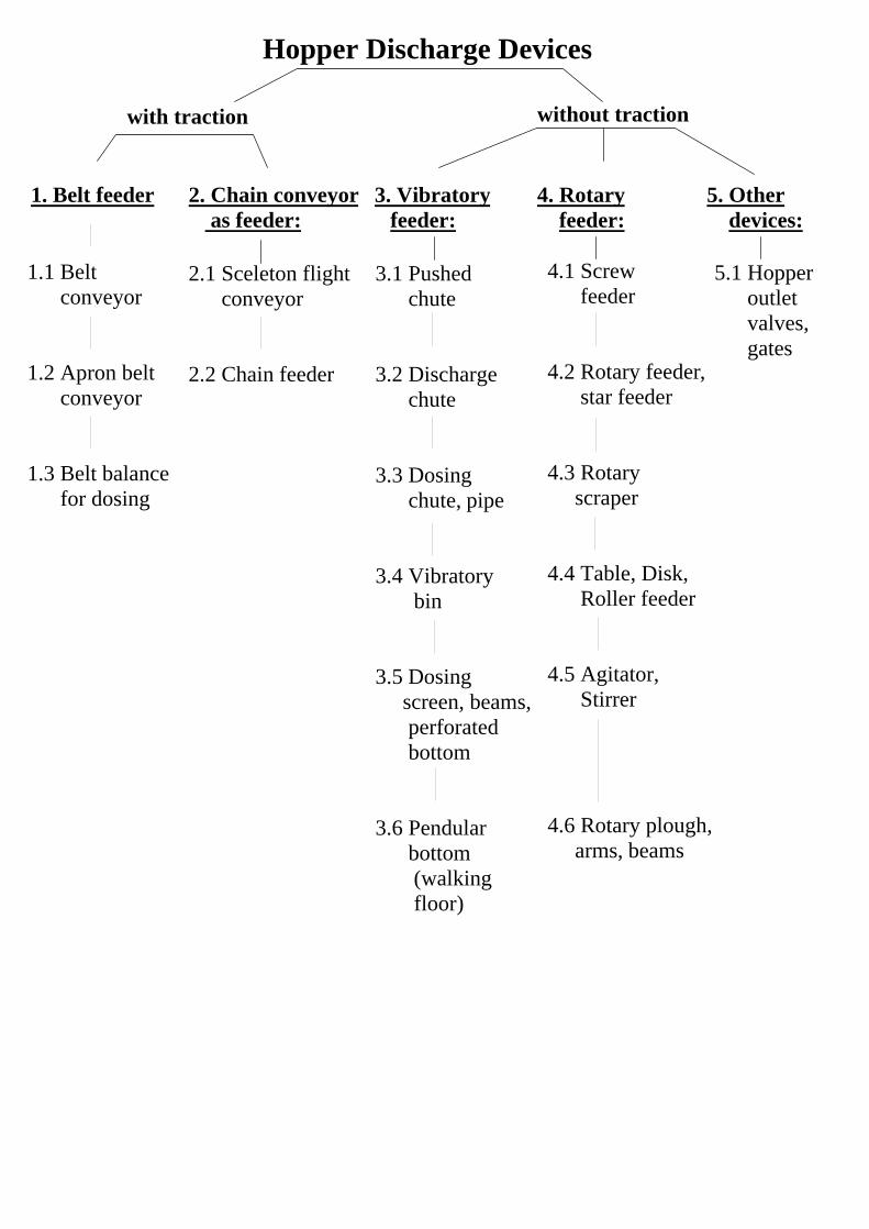
Arrangement of Bin-Feeder Interface for Mass Flow
1. Flange arrangement of bin-feeder transition 2. Double plates a) wrong b) right a) wrong b) right
3. a) gate with horizontal obstacle b) partially opened plate within the outlet area rotary valve
4. Discharge of easy flowing powder by rotary feeder
5. Arrangement of rotary plough feeder a) plough b) outer c) under- too short wall step scratching
dead zoens
chute interface
outlet cross section offeeder plate
closedsaddle
stagnant zone
plateopened
chutefitting turned to right
dead zone
deadzonesin theedges
free cross section
dead zone
deadzone
deadzone
no powderdischarge
stagnant zone
rotary plough
6. Draw-off behaviour of belt conveyor
a) in front at smooth belt and large b) uniform at sloping striker plate vertical gate opening, (increasing draw-off height) back at rough belt and small vertical gate opening
c) uniform at widen chute opening d) uniform at increasing weir level (sloping cross-sectional area of outlet) (sloping draw-off height)
7. Boundary (interface, shear zone) of horizontally drawn-off powder layer
8. Sceleton flight conveyor with sloping plates within chute interface
sloping plates, skirts or liners
trough,skeleton flight conveyor
direction ofconveying
aus: Schulze, D., Austragorgane und Austraghilfen, Chem.-Ing.-Techn. 65 (1993) 48-57
hopper outlet levelb) uniform powder draw-off
c) only in front draw-off
a) draw-off from back
gate or weir level andbulk heighton belt hB
Arrangement of Bin-Feeder Interface for Mass Flow
weir plates
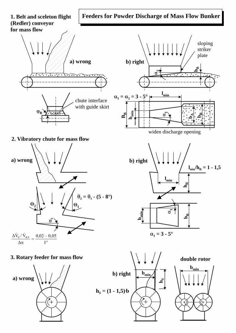
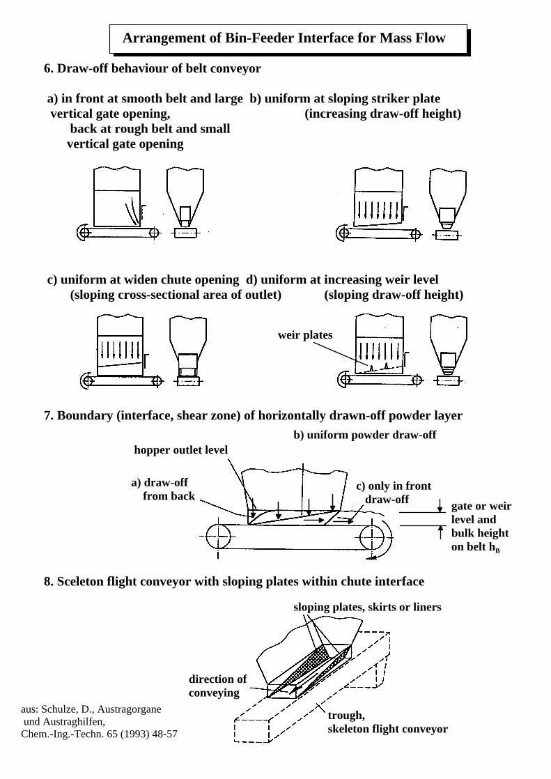
Feeders for Powder Discharge of Mass Flow Bunker1. Belt and sceleton flight (Redler) conveyorfor mass flow
3. Rotary feeder for mass flow
bmin
. .... . ... .
.
.. .. . . .. .. . . .. . ... . .......
B
chute interfacewith guide skirt
. . .... . . ..... . ....
lminh R
2
2 1
b min
b R
1lmin/hR = 1 - 1,5
BB
b min
...
. ... .. ... . .. . ..
.. .
........
. ..
.
...
.
.
.. .. . . ...
..
.. . .
.
.
....
.. .
... .... .
..
..
..
.. .. .. . .
1
2 h Bb A
. ...
. .
. ..
.
...
.
lmin
b B
sloping strikerplate
widen discharge opening
bmin
h S
2. Vibratory chute for mass flow
a) wrong b) right
a) wrong b) right
a) wrongb) right
2 = 1 - (5 - 8°)
1 = 3 - 5°
1 = 2 = 3 - 5°
double rotor
hS = (1 - 1,5).b
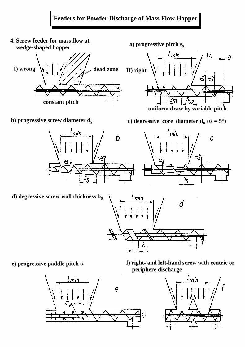
4. Screw feeder for mass flow at wedge-shaped hopper
I) wrong II) right
Feeders for Powder Discharge of Mass Flow Hopper
constant pitchuniform draw by variable pitch
a) progressive pitch sS
b) progressive screw diameter dS c) degressive core diameter dK ( = 5°)
d) degressive screw wall thickness bS
e) progressive paddle pitch f) right- and left-hand screw with centric or periphere discharge
dead zone
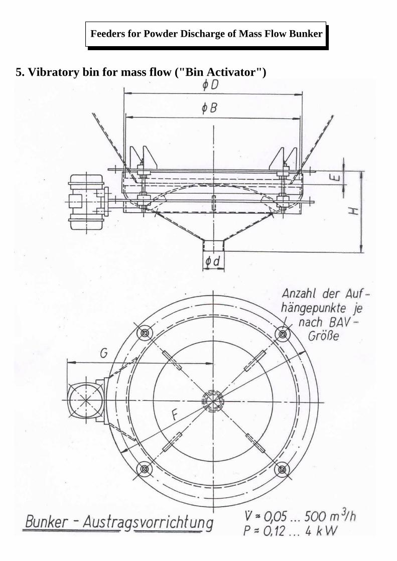
5. Vibratory bin for mass flow ("Bin Activator")
Feeders for Powder Discharge of Mass Flow Bunker
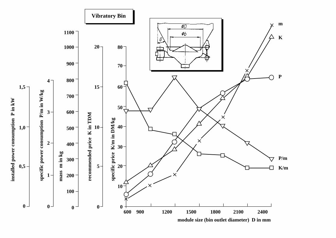
Vibratory Bin
600 900 1200 1500 1800 2100 2400
module size (bin outlet diameter) D in mm
1,5
1,0
0,5
0
inst
alle
d po
wer
con
sum
ptio
n P
in k
W
4
3
2
1
0
spec
ific
pow
er c
onsu
mpt
ion
P/m
in W
/kg
1100
1000
900
800
700
600
500
400
300
200
100
0
mas
s m
in k
g
20
15
10
5
0
reco
mm
ende
d pr
ice
K in
TD
M
80
70
60
50
40
30
20
0
10
spec
ific
pri
ce K
/m in
DM
/kg
m
K
P
P/m
K/m
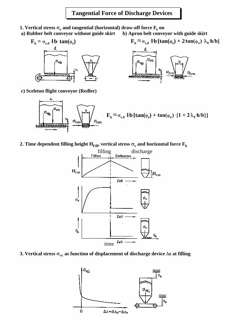
1. Vertical stress v and tangential (horizontal) draw-off force Fh on a) Rubber belt conveyor without guide skirt b) Apron belt conveyor with guide skirt
c) Sceleton flight conveyor (Redler)
2. Time dependent filling height HFill, vertical stress v and horizontal force Fh
3. Vertical stress vG as function of displacement of discharge device z at filling
Tangential Force of Discharge Devices
HFüll HFüll
filling discharge
time
Fh v,0 .l.b.[tan( e) + 2.≈
Fh v,0 .l.b.[tan( e) + ≈
Fh = v,0 .l.b. tan( e)
posit
ion
of a
ctiv
e sh
ear
plan
e
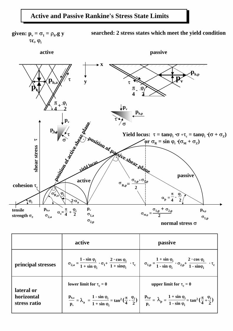
Active and Passive Rankine's Stress State Limits
Yield locus: = tan i · + c = tan i ·( + Z) or R = sin i ·( M + Z)
ph,a
activepassive
shea
r st
ress
tensile strength Z
cohesion c
i
2,aa=
i4 2+
iR ,a
2· a
pv
1,a
yield locus
ph,p
1,p
p = i
4 -
2
M,p =1,p + 2,p
2
position of passive shear plane
R,p=1,p 2,p
2
-
active passive
principal stresses
lateral orhorizontal stress ratio
2,a = · 1+ · c
1 - sin i
1 + sin i
2 · cos i
1 + sin i1,p = · 2,p+ · c
1 + sin i
1 - sin i
2 · cos i
1 - sin i
lower limit for c = 0 upper limit for c = 0
ph,p
pv
= = = tan21 + sin i
1 - sin i(
4 + i
2p
ph,a
pv
= = = tan21 - sin i
1 + sin i
(4
- i
2a
·
·
·
active
i
4 2+
pv
ph,apv
ph,p
passive
i
4 2-
pv
ph,a
pvph,p
normal stress
given: pv = 1 = b.g y c,
searched: 2 stress states which meet the yield condition
y
x
2,p
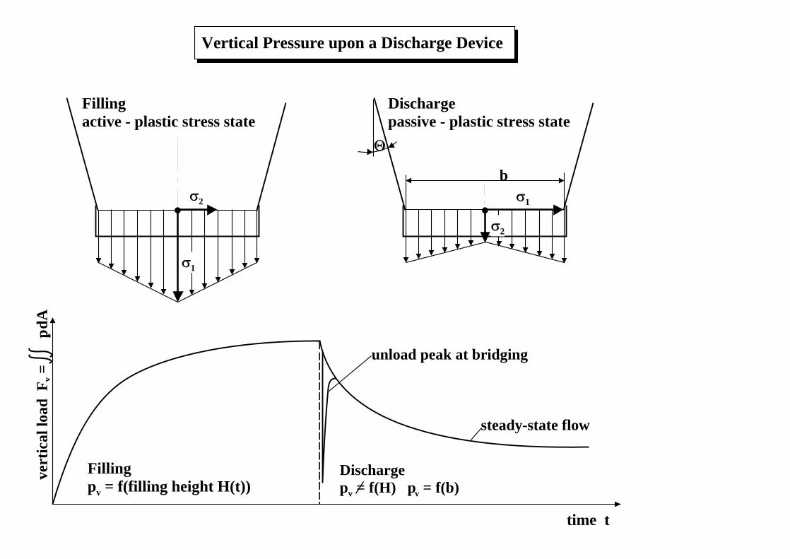
unload peak at bridging
steady-state flow
Fillingpv = f(filling height H(t))
time t
vert
ical
load
Fv =
p v d
A
1
b
Fillingactive - plastic stress state
Dischargepassive - plastic stress state
Vertical Pressure upon a Discharge Device
Dischargepv = f(H) pv = f(b)
2
2
1
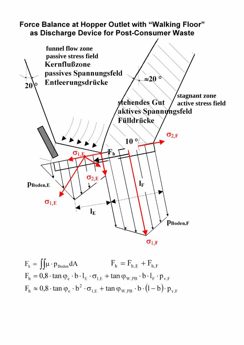
funnel flow zonepassive stress field
stagnant zoneactive stress field