HOMOGENIZED GLOBAL NONLINEAR CONSTITUTIVE MODEL …
11
11th World Congress on Computational Mechanics (WCCM XI) 5th European Conference on Computational Mechanics (ECCM V) 6th European Conference on Computational Fluid Dynamics (ECFD VI) E. Oñate, J. Oliver and A. Huerta (Eds) HOMOGENIZED GLOBAL NONLINEAR CONSTITUTIVE MODEL FOR RC PANELS UNDER CYCLIC LOADINGS MIQUEL HUGUET *† , FRANÇOIS VOLDOIRE § , PANAGIOTIS KOTRONIS * AND SILVANO ERLICHER † , * LUNAM Université, Ecole Centrale de Nantes, Université de Nantes, CNRS Institut de Recherche en Génie Civil et Mécanique (GeM) 1 rue de la Nöe 44321 Nantes, France e-mail: [email protected], www.ec-nantes.fr † EGIS Industries 4 Dolorès Ibarruri 93188 Montreuil, France email: [email protected], [email protected], www.egis.fr § Electricité de France R&D/AMA Laboratoire de Mécanique des Structures Industrielles Durables, UMR EDF–CNRS–CEA 8193 1 Avenue du Général de Gaulle F-92141, Clamart, France email: [email protected], www.edf.fr Key Words: Nonlinear analysis, Seismic design, Cracking, Global model, RC panels Summary. A new nonlinear stress resultant global constitutive model for RC panels is presented. Concrete damage, concrete stress transfer at cracks and bond-slip stress are the main nonlinear effects identified at the local scale that constitute the basis for the construction of the stress resultant global model through an analytical homogenization technique. The closed form solution is obtained using general functions for the previous phenomena. 1 INTRODUCTION Industrial buildings, in particular Nuclear Power Plants (NPP), are subjected to severe seismic requirements. These facilities, generally built in Reinforced Concrete (RC), have large dimensions and therefore time-expensive dynamic analyses are necessary. The use of global modeling approaches, which relate the stress resultant with the generalized strains using relative big size finite elements of RC material, can assure reasonable computational costs, numerical efficiency and robustness. This type of modeling strategy is often used in civil engineering design offices adopting linear elastic constitutive laws. However, recent requirements for NPP have led to the use of more realistic RC non-linear models. In this sense, two global nonlinear constitutive models for RC shells have been recently introduced in the Finite Element (FE) software Code_Aster [1], commonly used for the static and dynamic (including seismic) analysis of industrial buildings in France and, more
Transcript of HOMOGENIZED GLOBAL NONLINEAR CONSTITUTIVE MODEL …

11th World Congress on Computational Mechanics (WCCM XI)
5th European Conference on Computational Mechanics (ECCM V)
6th European Conference on Computational Fluid Dynamics (ECFD VI)
E. Oñate, J. Oliver and A. Huerta (Eds)
HOMOGENIZED GLOBAL NONLINEAR CONSTITUTIVE MODEL
FOR RC PANELS UNDER CYCLIC LOADINGS
MIQUEL HUGUET*†
, FRANÇOIS VOLDOIRE§
, PANAGIOTIS KOTRONIS* AND
SILVANO ERLICHER†,
* LUNAM Université, Ecole Centrale de Nantes, Université de Nantes, CNRS
Institut de Recherche en Génie Civil et Mécanique (GeM)
1 rue de la Nöe 44321 Nantes, France
e-mail: [email protected], www.ec-nantes.fr
† EGIS Industries
4 Dolorès Ibarruri 93188 Montreuil, France
email: [email protected], [email protected], www.egis.fr
§ Electricité de France R&D/AMA
Laboratoire de Mécanique des Structures Industrielles Durables, UMR EDF–CNRS–CEA 8193
1 Avenue du Général de Gaulle F-92141, Clamart, France
email: [email protected], www.edf.fr
Key Words: Nonlinear analysis, Seismic design, Cracking, Global model, RC panels
Summary. A new nonlinear stress resultant global constitutive model for RC panels is
presented. Concrete damage, concrete stress transfer at cracks and bond-slip stress are the
main nonlinear effects identified at the local scale that constitute the basis for the
construction of the stress resultant global model through an analytical homogenization
technique. The closed form solution is obtained using general functions for the previous
phenomena.
1 INTRODUCTION
Industrial buildings, in particular Nuclear Power Plants (NPP), are subjected to severe
seismic requirements. These facilities, generally built in Reinforced Concrete (RC), have
large dimensions and therefore time-expensive dynamic analyses are necessary. The use of
global modeling approaches, which relate the stress resultant with the generalized strains
using relative big size finite elements of RC material, can assure reasonable computational
costs, numerical efficiency and robustness. This type of modeling strategy is often used in
civil engineering design offices adopting linear elastic constitutive laws. However, recent
requirements for NPP have led to the use of more realistic RC non-linear models.
In this sense, two global nonlinear constitutive models for RC shells have been recently
introduced in the Finite Element (FE) software Code_Aster [1], commonly used for the static
and dynamic (including seismic) analysis of industrial buildings in France and, more
M. Huguet, F. Voldoire, P. Kotronis and S. Erlicher.
2
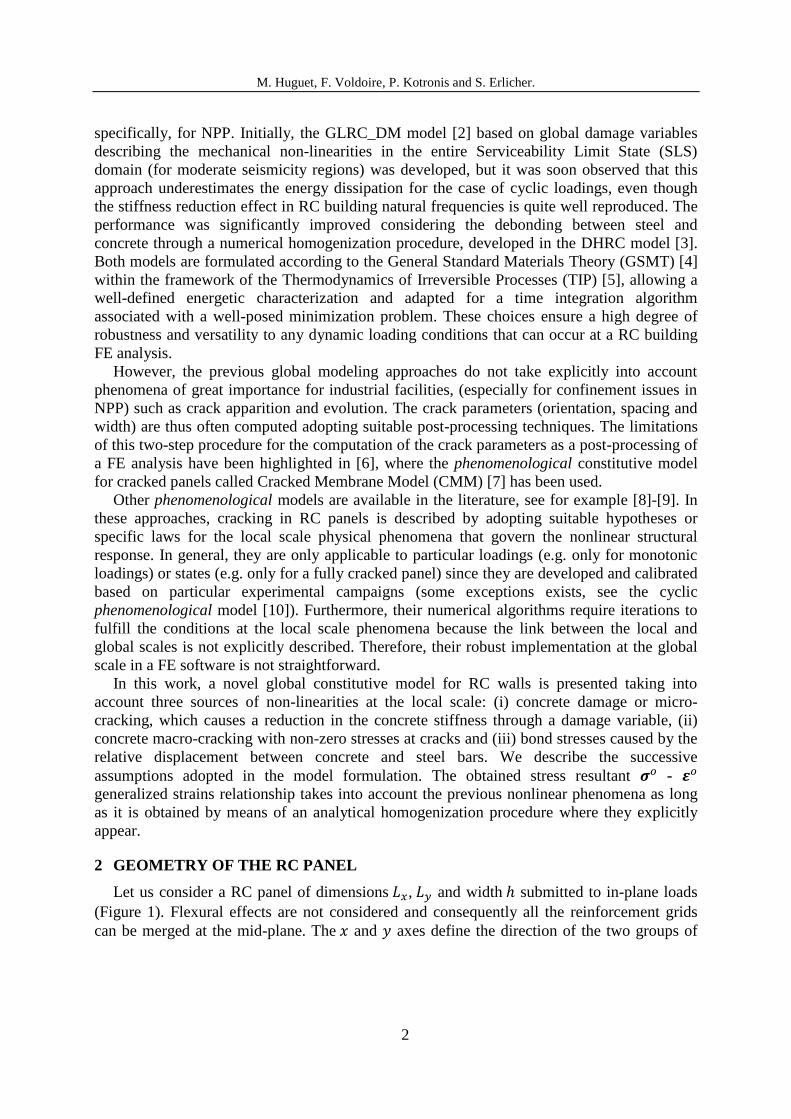
specifically, for NPP. Initially, the GLRC_DM model [2] based on global damage variables
describing the mechanical non-linearities in the entire Serviceability Limit State (SLS)
domain (for moderate seismicity regions) was developed, but it was soon observed that this
approach underestimates the energy dissipation for the case of cyclic loadings, even though
the stiffness reduction effect in RC building natural frequencies is quite well reproduced. The
performance was significantly improved considering the debonding between steel and
concrete through a numerical homogenization procedure, developed in the DHRC model [3].
Both models are formulated according to the General Standard Materials Theory (GSMT) [4]
within the framework of the Thermodynamics of Irreversible Processes (TIP) [5], allowing a
well-defined energetic characterization and adapted for a time integration algorithm
associated with a well-posed minimization problem. These choices ensure a high degree of
robustness and versatility to any dynamic loading conditions that can occur at a RC building
FE analysis.
However, the previous global modeling approaches do not take explicitly into account
phenomena of great importance for industrial facilities, (especially for confinement issues in
NPP) such as crack apparition and evolution. The crack parameters (orientation, spacing and
width) are thus often computed adopting suitable post-processing techniques. The limitations
of this two-step procedure for the computation of the crack parameters as a post-processing of
a FE analysis have been highlighted in [6], where the phenomenological constitutive model
for cracked panels called Cracked Membrane Model (CMM) [7] has been used.
Other phenomenological models are available in the literature, see for example [8]-[9]. In
these approaches, cracking in RC panels is described by adopting suitable hypotheses or
specific laws for the local scale physical phenomena that govern the nonlinear structural
response. In general, they are only applicable to particular loadings (e.g. only for monotonic
loadings) or states (e.g. only for a fully cracked panel) since they are developed and calibrated
based on particular experimental campaigns (some exceptions exists, see the cyclic
phenomenological model [10]). Furthermore, their numerical algorithms require iterations to
fulfill the conditions at the local scale phenomena because the link between the local and
global scales is not explicitly described. Therefore, their robust implementation at the global
scale in a FE software is not straightforward.
In this work, a novel global constitutive model for RC walls is presented taking into
account three sources of non-linearities at the local scale: (i) concrete damage or micro-
cracking, which causes a reduction in the concrete stiffness through a damage variable, (ii)
concrete macro-cracking with non-zero stresses at cracks and (iii) bond stresses caused by the
relative displacement between concrete and steel bars. We describe the successive
assumptions adopted in the model formulation. The obtained stress resultant -
generalized strains relationship takes into account the previous nonlinear phenomena as long
as it is obtained by means of an analytical homogenization procedure where they explicitly
appear.
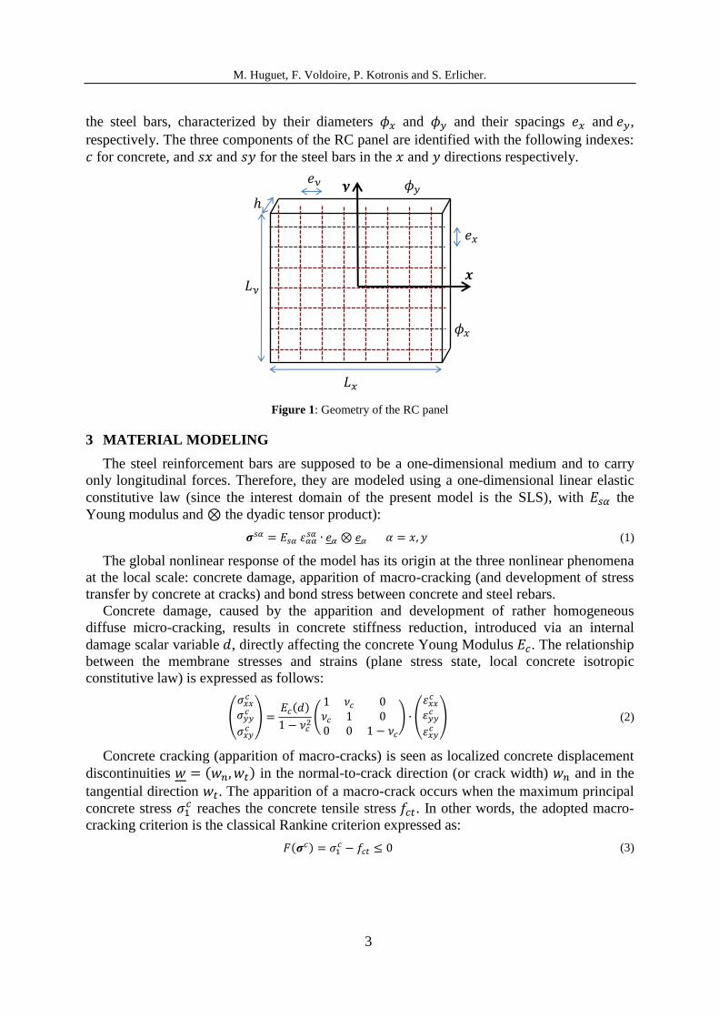
2 GEOMETRY OF THE RC PANEL
Let us consider a RC panel of dimensions , and width submitted to in-plane loads
(Figure 1). Flexural effects are not considered and consequently all the reinforcement grids
can be merged at the mid-plane. The and axes define the direction of the two groups of
M. Huguet, F. Voldoire, P. Kotronis and S. Erlicher.
3
the steel bars, characterized by their diameters and and their spacings and ,
respectively. The three components of the RC panel are identified with the following indexes:
for concrete, and and for the steel bars in the and directions respectively.
Figure 1: Geometry of the RC panel
3 MATERIAL MODELING
The steel reinforcement bars are supposed to be a one-dimensional medium and to carry
only longitudinal forces. Therefore, they are modeled using a one-dimensional linear elastic
constitutive law (since the interest domain of the present model is the SLS), with the
Young modulus and the dyadic tensor product):
(1)
The global nonlinear response of the model has its origin at the three nonlinear phenomena
at the local scale: concrete damage, apparition of macro-cracking (and development of stress
transfer by concrete at cracks) and bond stress between concrete and steel rebars.
Concrete damage, caused by the apparition and development of rather homogeneous
diffuse micro-cracking, results in concrete stiffness reduction, introduced via an internal
damage scalar variable , directly affecting the concrete Young Modulus . The relationship
between the membrane stresses and strains (plane stress state, local concrete isotropic
constitutive law) is expressed as follows:
(
) ( )
(
) (
) (2)
Concrete cracking (apparition of macro-cracks) is seen as localized concrete displacement
discontinuities ( ) in the normal-to-crack direction (or crack width) and in the
tangential direction . The apparition of a macro-crack occurs when the maximum principal
concrete stress reaches the concrete tensile stress . In other words, the adopted macro-
cracking criterion is the classical Rankine criterion expressed as:
( ) (3)
𝒚
𝒙
𝑒𝑥
𝑒𝑦
𝜙𝑥
𝜙𝑦
𝐿𝑦
𝐿𝑥

M. Huguet, F. Voldoire, P. Kotronis and S. Erlicher.
4
This criterion separates the behavior of the RC panel in two different phases: the uncracked
and the cracked one. The cracked phase can also be divided in two parts: the crack formation
(some cracks exist but other appear with increasing loading) and the stabilized crack phase
(no more cracks appear even with increasing loading), see e.g. [11]. However, the crack
formation phase can be considered to be negligible in a finite element with the usual modeling
dimensions, and in this work only the uncracked and the stabilized cracked phases are
considered. At cracks, the concrete stress transfer vector is considered, which has a normal
and a tangential component named and respectively. They both depend on the crack
opening displacement field and other internal variables noted hereafter :
( ) (4)
Finally, bond stresses ( ) transmitted from and reinforcement steel bars to
concrete are at the origin of the tension stiffening effect. They appear when a relative slip
( ) or steel-concrete debonding, associated with internal variables , occurs:
( ) (5)
4 ANALYTICAL HOMOGENIZATION OF THE CRACKED RC PANEL
In this section an analytical homogenization of a cracked RC panel is performed. In a
region of the panel far enough from non-regular boundary conditions, an identifiable
periodicity has to be identified in order to define the Reference Volume Element (RVE) of the
problem, that is the smallest volume able to represent the physical phenomena governing the
response of the material and which is repeated periodically in the space. After the
identification of the RVE, referring for instance to [12], the following steps, represented
schematically in Figure 2, have to be done:
i) Definition of the local stress fields as functions of an applied stress
resultant on the RVE (stress localization).
ii) Application of the local constitutive laws to obtain the local strain fields
.
iii) Application of the compatibility equations and the averaging method to obtain the
generalized strain field from the previous calculated fields.
Figure 2: Homogenization technique scheme
𝝈𝑜 𝜺𝑜
𝝈𝑙𝑜𝑐
𝝈𝑐 𝝈𝑠𝑥 𝝈𝑠𝑦
𝜺𝑙𝑜𝑐
𝜺𝑐 𝜺𝑠𝑥 𝜺𝑠𝑦
Compatibility
+
Averaging
Local constitutive laws
Global law
Localization
+
Averaging
M. Huguet, F. Voldoire, P. Kotronis and S. Erlicher.
5
Even though it is more usual to formulate this scheme by beginning with the strain field,
we prefer to take the stress resultant field to apply directly some useful equilibrium arguments
in the formulation. In steps i) and iii) the local-global scales passage is done by means of the
averaging method, based on the average value of a considered field in the RVE volume :
⟨ ⟩
| |∫
(6)
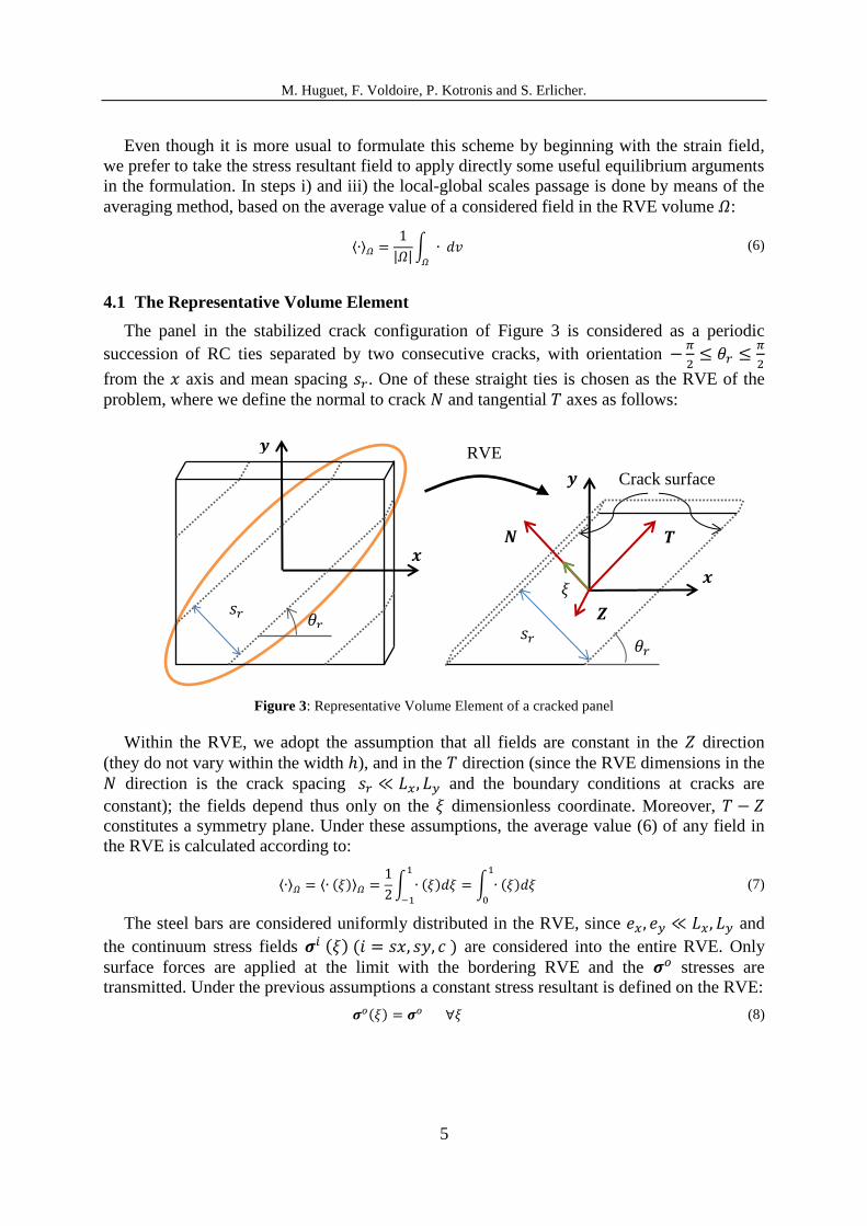
4.1 The Representative Volume Element
The panel in the stabilized crack configuration of Figure 3 is considered as a periodic
succession of RC ties separated by two consecutive cracks, with orientation
from the axis and mean spacing . One of these straight ties is chosen as the RVE of the
problem, where we define the normal to crack and tangential axes as follows:
Figure 3: Representative Volume Element of a cracked panel
Within the RVE, we adopt the assumption that all fields are constant in the direction
(they do not vary within the width ), and in the direction (since the RVE dimensions in the
direction is the crack spacing and the boundary conditions at cracks are
constant); the fields depend thus only on the dimensionless coordinate. Moreover,
constitutes a symmetry plane. Under these assumptions, the average value (6) of any field in
the RVE is calculated according to:
⟨ ⟩ ⟨ ( )⟩
∫ ( )
∫ ( )
(7)
The steel bars are considered uniformly distributed in the RVE, since and
the continuum stress fields ( ) ( ) are considered into the entire RVE. Only
surface forces are applied at the limit with the bordering RVE and the stresses are
transmitted. Under the previous assumptions a constant stress resultant is defined on the RVE:
( ) (8)
𝒚
𝒙
𝜃𝑟 𝑠𝑟
𝒚
𝒙
𝑻 𝑵
𝑠𝑟 𝜃𝑟
𝜉
Crack surface
𝒁
RVE
M. Huguet, F. Voldoire, P. Kotronis and S. Erlicher.
6
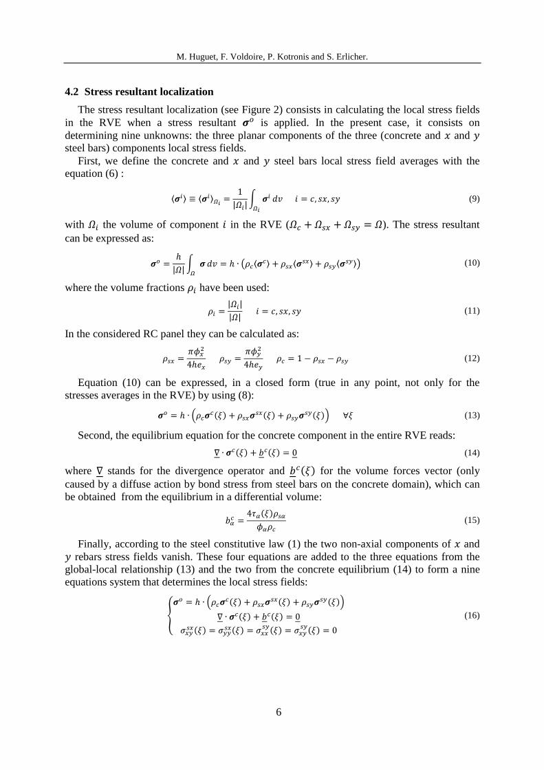
4.2 Stress resultant localization
The stress resultant localization (see Figure 2) consists in calculating the local stress fields
in the RVE when a stress resultant is applied. In the present case, it consists on
determining nine unknowns: the three planar components of the three (concrete and and
steel bars) components local stress fields.
First, we define the concrete and and steel bars local stress field averages with the
equation (6) :
⟨ ⟩ ⟨ ⟩
| |∫
(9)
with the volume of component in the RVE ( ). The stress resultant
can be expressed as:
| |∫
( ⟨ ⟩ ⟨
⟩ ⟨ ⟩) (10)
where the volume fractions have been used:
| |
| | (11)
In the considered RC panel they can be calculated as:
(12)
Equation (10) can be expressed, in a closed form (true in any point, not only for the
stresses averages in the RVE) by using (8):
( ( )
( ) ( )) (13)
Second, the equilibrium equation for the concrete component in the entire RVE reads:
( ) ( ) (14)
where stands for the divergence operator and ( ) for the volume forces vector (only
caused by a diffuse action by bond stress from steel bars on the concrete domain), which can
be obtained from the equilibrium in a differential volume:
( )
(15)
Finally, according to the steel constitutive law (1) the two non-axial components of and
rebars stress fields vanish. These four equations are added to the three equations from the
global-local relationship (13) and the two from the concrete equilibrium (14) to form a nine
equations system that determines the local stress fields:
{
( ( )
( ) ( ))
( ) ( )
( )
( ) ( )
( )
(16)
M. Huguet, F. Voldoire, P. Kotronis and S. Erlicher.
7
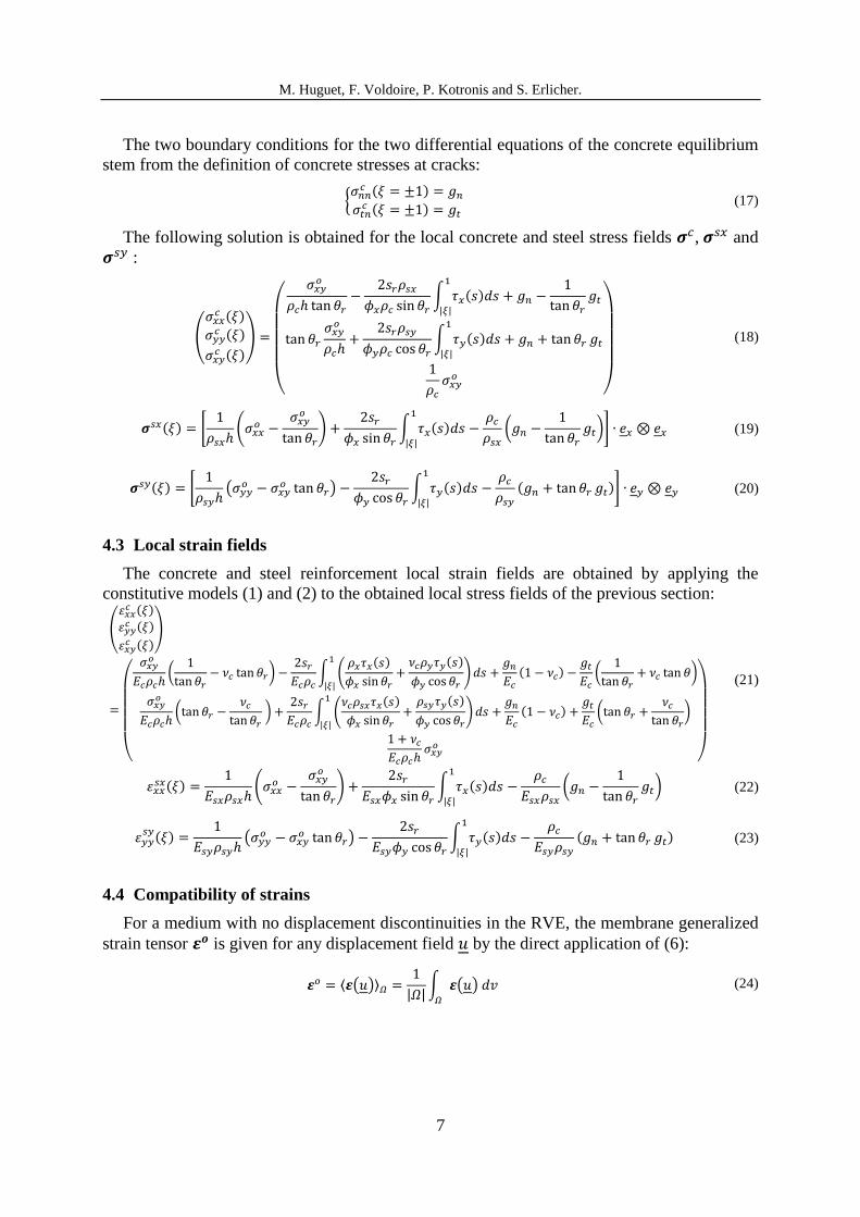
The two boundary conditions for the two differential equations of the concrete equilibrium
stem from the definition of concrete stresses at cracks:
{
( )
( )
(17)
The following solution is obtained for the local concrete and steel stress fields , and
:
(
( )
( )
( )
)
(
∫ ( )
| |
∫ ( )
| |
)
(18)
( ) [
(
)
∫ ( )
| |
(
)] (19)
( ) [
(
)
∫ ( )
| |
( )] (20)
4.3 Local strain fields
The concrete and steel reinforcement local strain fields are obtained by applying the
constitutive models (1) and (2) to the obtained local stress fields of the previous section:
(
( )
( )
( )
)
(
(
)
∫ (
( )
( )
)
| |
( )
(
)
(
)
∫ (
( )
( )
)
| |
( )
(
)
)
(21)
( )
(
)
∫ ( )
| |
(
) (22)
( )
(
)
∫ ( )
| |
( ) (23)
4.4 Compatibility of strains
For a medium with no displacement discontinuities in the RVE, the membrane generalized
strain tensor is given for any displacement field by the direct application of (6):
⟨ ( )⟩
| |∫ ( )
(24)

M. Huguet, F. Voldoire, P. Kotronis and S. Erlicher.
8
When a displacement discontinuity ⟦ ⟧ on a particular regular boundary within the RVE
is considered (denoting by the local unit normal vector on and by the symmetric
dyadic tensor product), the following amendment of the previous expression is made
(referring to the Stokes’ theorem):
| |(∫ ( )
∫ ⟦ ⟧
) (25)
Equation (24) is used for the calculation of and
from and steel bars strain fields
respectively, while (25) is used for calculating the three components of from the concrete
local strain field, with ⟦ ⟧ the displacement discontinuity at cracks :
{
⟨ ⟩
⟨
⟩
⟨ ⟩
(26)
where the equivalent strains due to cracks in the coordinates system are calculated as:
(
) (27)
The averages of the local strain fields (21), (22) and (23) are calculated with (7) and
inserted in (26). A five equations system linking the stress resultants to the generalized
strains and the internal variables is obtained:
{
(
)
(
)
(
)
( )
(
)
(
)
( )
(
)
(
)
(
)
( )
(
)
(28)
where the average bond-slip stress is defined:
⟨∫ ( )
| |
⟩ ∫ ∫ ( )
| |
(29)
Details about these developments and the complete thermodynamic formulation of the
general model can be found in [13]. We briefly describe hereafter a particular one-
dimensional case.
5 EXAMPLE: A ONE-DIMENSIONAL DAMAGE MODEL
As an example of application of the developed general model, one of the simplest
particular cases is reproduced hereafter: a one-dimensional damage model where crack
development and bond stresses are not explicitly taken into account. The GLRC_DM [2]
damage approach accounting for a constant slope in the relationship while damage
evolves is adopted.
M. Huguet, F. Voldoire, P. Kotronis and S. Erlicher.
9
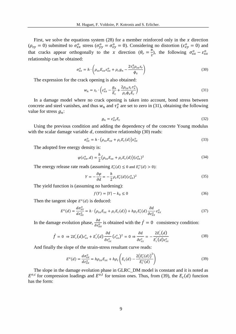
First, we solve the equations system (28) for a member reinforced only in the direction
( ) submitted to stress (
). Considering no distortion (
) and
that cracks appear orthogonally to the direction (
), the following
relationship can be obtained:
(
) (30)
The expression for the crack opening is also obtained:
(
) (31)
In a damage model where no crack opening is taken into account, bond stress between
concrete and steel vanishes, and thus and are set to zero in (31), obtaining the following
value for stress :
(32)
Using the previous condition and adding the dependency of the concrete Young modulus
with the scalar damage variable , constitutive relationship (30) reads:
( ( ))
(33)
The adopted free energy density is:
( )
( ( ))(
) (34)
The energy release rate reads (assuming ( ) and
( ) ):
( )( ) (35)
The yield function is (assuming no hardening):
( ) | | (36)
Then the tangent slope ( ) is deduced:
( )
( ( )) ( )
(37)
In the damage evolution phase,
is obtained with the consistency condition:
( )
( )
( )
( )
( )
(38)
And finally the slope of the strain-stress resultant curve reads:
( )
( ( ) (
( ))
( )
) (39)
The slope in the damage evolution phase in GLRC_DM model is constant and it is noted as
for compression loadings and for tension ones. Thus, from (39), the ( ) function
has the form:

M. Huguet, F. Voldoire, P. Kotronis and S. Erlicher.
10
( ) ( )
(
) ( )
(40)
with , undefined parameters.
This model is applied to the experimental test described in [14], consisting in a one-
dimensional RC member length, section, reinforced with 4 rebars
( diameter) and Young modulus , and with a concrete
characterized by an initial Young modulus , tensile strength
and compressive strength . and parameters are set to and
respectively, and is set to . Finally, we use and in order
to set the damage beginning at for tension loadings and for the compression ones.
The comparison of Figure 4 (a) between the experimental and the numerical results shows
a quite good agreement. However, dissipation is underestimated as long as the hysteretic
experimental response is not well reproduced. In [13] it is showed that the dissipation can be
better assessed for the tension loading domain when the developed model in section 4 is
applied for the case where crack opening is allowed and modeled using suitable functions for
bond stresses and concrete stress transfer at cracks; the obtained results with this model are
also plotted in Figure 4 (b).
Figure 4: Comparison between numerical and experiment results for a one-dimensional RC member
6 CONCLUSIONS
A general nonlinear constitutive model for RC panels has been developed. Nonlinear
phenomena at the local scale (concrete micro and macro cracking, steel-concrete debonding)
appear in an explicit manner by means of general functions on the global formulation of the
model as a result of an analytical homogenization technique. A particular one-dimensional
case is finally presented in order to show the applicability of the model.
-1000
-800
-600
-400
-200
0
200
400
-2,E-03 -1,E-03 0,E+00 1,E-03 2,E-03 3,E-03
Forc
e (
KN
)
Strain
Experimental
Damage model
-1000
-800
-600
-400
-200
0
200
400
-2,E-03 -1,E-03 0,E+00 1,E-03 2,E-03 3,E-03
Forc
e (
KN
)
Strain
Experimental
Damage + crack model
(a) (b)

M. Huguet, F. Voldoire, P. Kotronis and S. Erlicher.
11
ACKNOWLEGDEMENTS
This work, performed within the RSRN project (“Recherche dans le domaine de la Sureté
Nucléaire et de la Radioprotection”), has been financed by the French Agence Nationale de la
Recherche, program “Investissements d’avenir”, ANR-11-RSNR-0022 (ANR SINAPS@),
and the first author is also partly supported by the French Association Nationale de la
Recherche et de la Technologie.
REFERENCES
[1] Code_Aster, general public licensed structural mechanics finite element software,
Internet site: http://www.code-aster.org
[2] Markovic, D., Koechlin, P. and Voldoire, F., Reinforced concrete structures under
extreme loading: Stress resultant Global Reinforced Concrete Models (GLRC). Proc.
COMPDYN 2007, Rethymno, Greece.
[3] Combescure, C., Dumontet, H. and Voldoire, F. Homogenized constitutive model
coupling damage and debonding for reinforced concrete structures under cyclic
solicitations. Int. J. Solids Struct. (2013) 50:3861-3874.
[4] Halphen, B. and Nguyen, Q.S. Sur les matériaux standards généralisés. J. Mécanique
(1975) 14:39-63.
[5] Lemaitre, J. and Chaboche, J.L. Mechanics of Solid Materials. Cambridge University
Press (1994).
[6] Ruocci, G., Huguet, M., Erlicher, S. and Bisch, P. Crack orientation, distance and width
in reinforced concrete membranes: experimental results and preliminary interpretations
based on the Cracked Membrane Model. Proc. TINCE 2013, Paris, France.
[7] Kaufmann, W. and Marti, P. Structural concrete: cracked membrane model. J. Struct.
Eng. (1998) 124(12):1467-1475.
[8] Vecchio, F.J. and Collins, M.P. The modified compression field theory for reinforced
concrete elements subjected to shear. ACI Journal (1986) 83(2):219-231.
[9] Pimentel, M., Bruwhiler, E. and Figueiras, J. Extended cracked membrane model for the
analysis of RC panels. Eng. Struct. (2010) 32:1964-1975.
[10] Palermo, D. and Vecchio, F.J. Compression field modeling of reinforced concrete
subjected to reversed loading: formulation. ACI Struct. J. (2003) 100(5):616-625.
[11] Fédération Internationale du Béton (fib). Model Code 2010.
[12] Sanchez-Palencia, E., Zaoui, A. and Suquet, P. Homogenization Technique for Composite
Media. Springer, Berlin Heidelberg (1987).
[13] Huguet, M., Erlicher, S., Kotronis, P. and Voldoire, F. Homogenized nonlinear stress
resultant constitutive model for cracked reinforced concrete panels. Int. J. Solids Struct.
(under submission).
[14] Benmansour, M.B. Modélisation du comportement cyclique alterné du béton armé.
Application à divers essais statiques de poteaux. PhD Thesis, Ecole Nationale des Ponts
et Chaussées (1997).