Homogenization on microstructure and mechanical properties ... · Homogenization on microstructure...
7
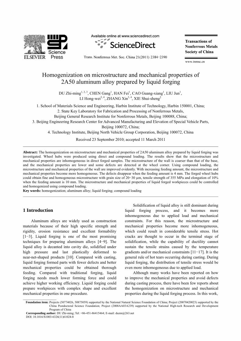
Homogenization on microstructure and mechanical properties of 2A50 aluminum alloy prepared by liquid forging DU Zhi-ming 1, 2, 3 , CHEN Gang 1 , HAN Fei 1 , CAO Guang-xiang 1 , LIU Jun 1 , LI Hong-wei 3, 4 , ZHANG Xin 3, 4 , XIE Shui-sheng 2 1. School of Materials Science and Engineering, Harbin Institute of Technology, Harbin 150001, China; 2. State Key Laboratory for Fabrication and Processing of Nonferrous Metals, Beijing General Research Institute for Nonferrous Metals, Beijing 100088, China; 3. Beijing Engineering Research Center for Advanced Manufacturing and Elevation of Special Vehicle Parts, Beijing 100072, China; 4. Technology Institute, Beijing North Vehicle Group Corporation, Beijing 100072, China Received 23 September 2010; accepted 11 March 2011 Abstract: The homogenization on microstructure and mechanical properties of 2A50 aluminum alloy prepared by liquid forging was investigated. Wheel hubs were produced using direct and compound loading. The results show that the microstructure and mechanical properties are inhomogeneous in direct forged samples. The microstructure of the wall is coarser than that of the base, and the mechanical properties are lower and some defects are detected at the wheel corner. Using compound loading, the microstructure and mechanical properties of the wall are improved evidently. With increasing feeding amount, the microstructure and mechanical properties become more homogeneous. The defects disappear when the feeding amount is 4 mm. The forged wheel hubs could obtain fine and homogeneous microstructure with grain size of 20−30 μm, tensile strength of 355 MPa and elongation of 10% when the feeding amount is 10 mm. The microstructure and mechanical properties of liquid forged workpieces could be controlled and homogenized using compound loading. Key words: homogenization; aluminum alloy; liquid forging; compound loading 1 Introduction Aluminum alloys are widely used as construction materials because of their high specific strength and rigidity, erosion resistance and excellent formability [1−3]. Liquid forging is one of the most promising techniques for preparing aluminum alloys [4−9]. The liquid alloy is decanted into cavity die, solidified under high pressure and last plastically deformed to near-net-shaped products [10]. Compared with casting, liquid forging formed parts with fewer defects and better mechanical properties could be obtained thorough feeding. Compared with traditional forging, liquid forging needs much lower forming force and could achieve higher working efficiency. Liquid forging could prepare workpieces with complex shape and excellent mechanical properties in one procedure. Solidification of liquid alloy is still dominant during liquid forging process, and it becomes more inhomogeneous due to applied load and mechanical constraints. For this reason, the microstructure and mechanical properties become more inhomogeneous, which could result in considerable tensile stress. Hot cracks are thought to occur in the terminal stage of solidification, while the capability of ductility cannot sustain the tensile strains caused by the temperature gradients and/or mechanical constraints [11−17]. It is the general rule of hot tears occurring during casting. During liquid forging, the distribution of tensile stress would be even more inhomogeneous due to applied load. Although many works have been reported on how to improve the mechanical properties and avoid defects during casting process, there have been few reports about the homogenization on microstructure and mechanical properties during the liquid forging process. In this work, Foundation item: Projects (50774026, 50875059) supported by the National Natural Science Foundation of China; Project (20070420023) supported by the China Postdoctoral Science Foundation; Project (2008AA03A239) supported by the National High-tech Research and Development Program of China Corresponding author: DU Zhi-ming; Tel: +86-451-86415464; E-mail: [email protected] DOI: 10.1016/S1003-6326(11)61024-8
Transcript of Homogenization on microstructure and mechanical properties ... · Homogenization on microstructure...
Homogenization on microstructure and mechanical properties of
2A50 aluminum alloy prepared by liquid forging
DU Zhi-ming1, 2, 3, CHEN Gang1, HAN Fei1, CAO Guang-xiang1, LIU Jun1, LI Hong-wei3, 4, ZHANG Xin3, 4, XIE Shui-sheng2
1. School of Materials Science and Engineering, Harbin Institute of Technology, Harbin 150001, China;
2. State Key Laboratory for Fabrication and Processing of Nonferrous Metals, Beijing General Research Institute for Nonferrous Metals, Beijing 100088, China;
3. Beijing Engineering Research Center for Advanced Manufacturing and Elevation of Special Vehicle Parts, Beijing 100072, China;
4. Technology Institute, Beijing North Vehicle Group Corporation, Beijing 100072, China
Received 23 September 2010; accepted 11 March 2011
Abstract: The homogenization on microstructure and mechanical properties of 2A50 aluminum alloy prepared by liquid forging was investigated. Wheel hubs were produced using direct and compound loading. The results show that the microstructure and mechanical properties are inhomogeneous in direct forged samples. The microstructure of the wall is coarser than that of the base, and the mechanical properties are lower and some defects are detected at the wheel corner. Using compound loading, the microstructure and mechanical properties of the wall are improved evidently. With increasing feeding amount, the microstructure and mechanical properties become more homogeneous. The defects disappear when the feeding amount is 4 mm. The forged wheel hubs could obtain fine and homogeneous microstructure with grain size of 20−30 µm, tensile strength of 355 MPa and elongation of 10% when the feeding amount is 10 mm. The microstructure and mechanical properties of liquid forged workpieces could be controlled and homogenized using compound loading. Key words: homogenization; aluminum alloy; liquid forging; compound loading 1 Introduction
Aluminum alloys are widely used as construction materials because of their high specific strength and rigidity, erosion resistance and excellent formability [1−3]. Liquid forging is one of the most promising techniques for preparing aluminum alloys [4−9]. The liquid alloy is decanted into cavity die, solidified under high pressure and last plastically deformed to near-net-shaped products [10]. Compared with casting, liquid forging formed parts with fewer defects and better mechanical properties could be obtained thorough feeding. Compared with traditional forging, liquid forging needs much lower forming force and could achieve higher working efficiency. Liquid forging could prepare workpieces with complex shape and excellent mechanical properties in one procedure.
Solidification of liquid alloy is still dominant during liquid forging process, and it becomes more inhomogeneous due to applied load and mechanical constraints. For this reason, the microstructure and mechanical properties become more inhomogeneous, which could result in considerable tensile stress. Hot cracks are thought to occur in the terminal stage of solidification, while the capability of ductility cannot sustain the tensile strains caused by the temperature gradients and/or mechanical constraints [11−17]. It is the general rule of hot tears occurring during casting. During liquid forging, the distribution of tensile stress would be even more inhomogeneous due to applied load.
Although many works have been reported on how to improve the mechanical properties and avoid defects during casting process, there have been few reports about the homogenization on microstructure and mechanical properties during the liquid forging process. In this work,
Foundation item: Projects (50774026, 50875059) supported by the National Natural Science Foundation of China; Project (20070420023) supported by the
China Postdoctoral Science Foundation; Project (2008AA03A239) supported by the National High-tech Research and Development Program of China
Corresponding author: DU Zhi-ming; Tel: +86-451-86415464; E-mail: [email protected] DOI: 10.1016/S1003-6326(11)61024-8
DU Zhi-ming, et al/Trans. Nonferrous Met. Soc. China 21(2011) 2384−2390 2385
wheel hubs of 2A50 aluminum alloy were prepared using direct and compound loading. The homogenization on microstructure and mechanical properties was investigated with different feeding amounts. 2 Experimental
The composition of 2A50 aluminum alloy investigated in this study is listed in Table 1. The solidus and liquidus temperatures of this alloy were obtained at 521 and 615 °C using differential thermal analysis (DTA). Table 1 Composition of 2A50 aluminum alloy (mass fraction, %)
Si Fe Cu Mn Mg Ni Zn Ti Al0.7−1.2 0.7 1.8−2.6 0.4−0.8 0.4−0.8 0.10 0.30 0.15 Bal.
Wheel hubs were prepared using direct and
compound loading, as shown in Fig. 1. The external diameter, internal diameter and thickness are 440, 418 and 13 mm, respectively. Figure 2 shows the direct and compound loadings. As shown in Fig.2, the left side shows the direct loading, the punch applies pressure on the liquid aluminum alloy directly. The right side shows the compound loading, the external and internal punch apply on the liquid alloy, respectively, and the wall could obtain partial loading and liquid feeding.
Fig. 1 Dimension of wheel hub (Unit: mm)
Fig. 2 Schematic diagram of direct and compound loading
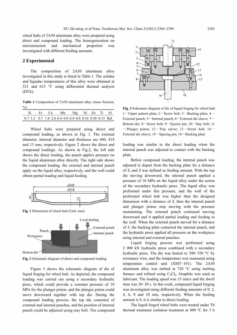
Figure 3 shows the schematic diagram of die of liquid forging for wheel hub. As depicted, the compound loading was carried out using a secondary hydraulic press, which could provide a constant pressure of 10 MPa for the plunger piston, and the plunger piston could move downward together with top die. During the compound loading process, the top die consisted of external and internal punches, and the position of internal punch could be adjusted using stay bolt. The compound
Fig. 3 Schematic diagram of die of liquid forging for wheel hub: 1—Upper pattern plate; 2—Screw bolt; 3—Backing plate; 4—External punch; 5—Internal punch; 6—External die sleeve; 7—Bottom die; 8—Screw bolt; 9—Ejector pin; 10—Stay bolt; 11—Plunger piston; 12—Tray salver; 13—Screw bolt; 14—External die sleeve; 15—Spacing pin; 16—Backing plate loading was similar to the direct loading when the internal punch was adjusted to contact with the backing plate.
Before compound loading, the internal punch was adjusted to depart from the backing plate for a distance of S, and S was defined as feeding amount. With the top die moving downward, the internal punch applied a pressure of 10 MPa on the liquid alloy under the action of the secondary hydraulic press. The liquid alloy was preformed under this pressure, and the wall of the preformed wheel hub was higher than the designed dimension with a distance of S, then the internal punch and plunger piston stop moving with the pressure maintaining. The external punch continued moving downward and it applied partial loading and feeding to the wall. When the external punch moved for a distance of S, the backing plate contacted the internal punch, and the hydraulic press applied all pressure on the workpiece using internal and external punches.
Liquid forging process was performed using 2 000 kN hydraulic press combined with a secondary hydraulic press. The die was heated to 300−350 °C by resistance wire, and the temperature was measured using temperature control unit (XMT−101). The 2A50 aluminum alloy was melted at 720 °C using melting furnace and refined using C2Cl6. Graphite was used as lubricant. The loading speed was 15 mm/s and the dwell time was 20−30 s. In this work, compound liquid forging was investigated using different feeding amounts of 0, 2, 4, 6, 8 and 10 mm, respectively. When the feeding amount is 0, it is similar to direct loading.
The liquid forged wheel hubs were treated under T6 thermal treatment (solution treatment at 490 °C for 3 h
DU Zhi-ming, et al/Trans. Nonferrous Met. Soc. China 21(2011) 2384−2390 2386
plus aging treatment at 160 °C for 10 h), and then some samples were sectioned for investigation. Samples for optical metallography were grind and polished by standard techniques, and then etched for about 20 s with 2.5%HNO3+1.5%HCl+1%HF aqueous solution [18−20]. Fracture surface of cracks was investigated using S−4700 scanning electronic microscope. The true density of samples was obtained using Archimedes principle, and the equation for calculating the density is as follows: Ρ=ρ1×m/(m−m1+m2) (1) where m is the tested mass of sample in air; m1 is the tested mass of sample and hang spring in distilled water; m2 is the tested mass of hang spring in distilled water; and ρ1 is the density of distilled water at tested temperature. Tensile tests were carried out using INSTRON 5582 universal testing machine. Each tensile or density result is the average of three measurements.
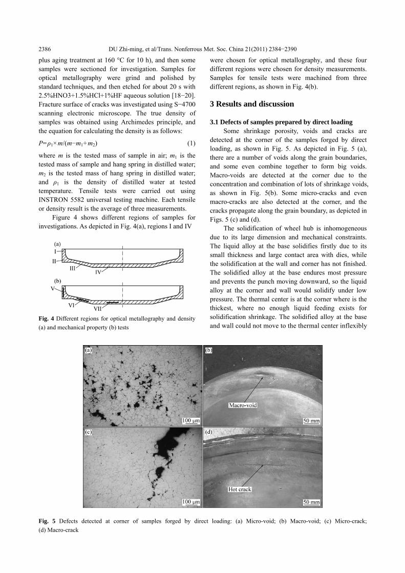
Figure 4 shows different regions of samples for investigations. As depicted in Fig. 4(a), regions I and IV
Fig. 4 Different regions for optical metallography and density (a) and mechanical property (b) tests
were chosen for optical metallography, and these four different regions were chosen for density measurements. Samples for tensile tests were machined from three different regions, as shown in Fig. 4(b). 3 Results and discussion 3.1 Defects of samples prepared by direct loading
Some shrinkage porosity, voids and cracks are detected at the corner of the samples forged by direct loading, as shown in Fig. 5. As depicted in Fig. 5 (a), there are a number of voids along the grain boundaries, and some even combine together to form big voids. Macro-voids are detected at the corner due to the concentration and combination of lots of shrinkage voids, as shown in Fig. 5(b). Some micro-cracks and even macro-cracks are also detected at the corner, and the cracks propagate along the grain boundary, as depicted in Figs. 5 (c) and (d).
The solidification of wheel hub is inhomogeneous due to its large dimension and mechanical constraints. The liquid alloy at the base solidifies firstly due to its small thickness and large contact area with dies, while the solidification at the wall and corner has not finished. The solidified alloy at the base endures most pressure and prevents the punch moving downward, so the liquid alloy at the corner and wall would solidify under low pressure. The thermal center is at the corner where is the thickest, where no enough liquid feeding exists for solidification shrinkage. The solidified alloy at the base and wall could not move to the thermal center inflexibly
Fig. 5 Defects detected at corner of samples forged by direct loading: (a) Micro-void; (b) Macro-void; (c) Micro-crack; (d) Macro-crack
DU Zhi-ming, et al/Trans. Nonferrous Met. Soc. China 21(2011) 2384−2390 2387
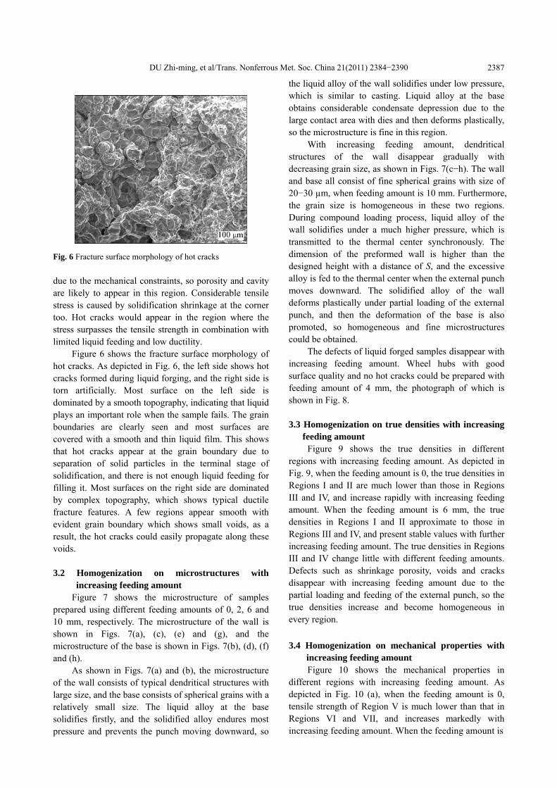
Fig. 6 Fracture surface morphology of hot cracks due to the mechanical constraints, so porosity and cavity are likely to appear in this region. Considerable tensile stress is caused by solidification shrinkage at the corner too. Hot cracks would appear in the region where the stress surpasses the tensile strength in combination with limited liquid feeding and low ductility.
Figure 6 shows the fracture surface morphology of hot cracks. As depicted in Fig. 6, the left side shows hot cracks formed during liquid forging, and the right side is torn artificially. Most surface on the left side is dominated by a smooth topography, indicating that liquid plays an important role when the sample fails. The grain boundaries are clearly seen and most surfaces are covered with a smooth and thin liquid film. This shows that hot cracks appear at the grain boundary due to separation of solid particles in the terminal stage of solidification, and there is not enough liquid feeding for filling it. Most surfaces on the right side are dominated by complex topography, which shows typical ductile fracture features. A few regions appear smooth with evident grain boundary which shows small voids, as a result, the hot cracks could easily propagate along these voids. 3.2 Homogenization on microstructures with
increasing feeding amount Figure 7 shows the microstructure of samples
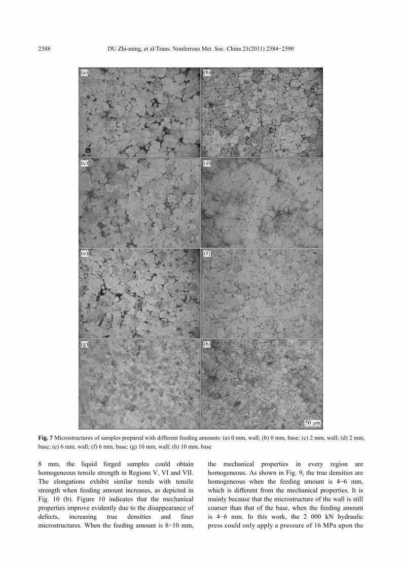
prepared using different feeding amounts of 0, 2, 6 and 10 mm, respectively. The microstructure of the wall is shown in Figs. 7(a), (c), (e) and (g), and the microstructure of the base is shown in Figs. 7(b), (d), (f) and (h).
As shown in Figs. 7(a) and (b), the microstructure of the wall consists of typical dendritical structures with large size, and the base consists of spherical grains with a relatively small size. The liquid alloy at the base solidifies firstly, and the solidified alloy endures most pressure and prevents the punch moving downward, so
the liquid alloy of the wall solidifies under low pressure, which is similar to casting. Liquid alloy at the base obtains considerable condensate depression due to the large contact area with dies and then deforms plastically, so the microstructure is fine in this region.
With increasing feeding amount, dendritical structures of the wall disappear gradually with decreasing grain size, as shown in Figs. 7(c−h). The wall and base all consist of fine spherical grains with size of 20−30 µm, when feeding amount is 10 mm. Furthermore, the grain size is homogeneous in these two regions. During compound loading process, liquid alloy of the wall solidifies under a much higher pressure, which is transmitted to the thermal center synchronously. The dimension of the preformed wall is higher than the designed height with a distance of S, and the excessive alloy is fed to the thermal center when the external punch moves downward. The solidified alloy of the wall deforms plastically under partial loading of the external punch, and then the deformation of the base is also promoted, so homogeneous and fine microstructures could be obtained.
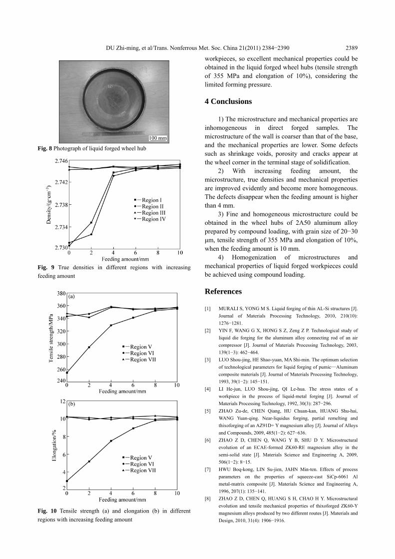
The defects of liquid forged samples disappear with increasing feeding amount. Wheel hubs with good surface quality and no hot cracks could be prepared with feeding amount of 4 mm, the photograph of which is shown in Fig. 8. 3.3 Homogenization on true densities with increasing
feeding amount Figure 9 shows the true densities in different
regions with increasing feeding amount. As depicted in Fig. 9, when the feeding amount is 0, the true densities in Regions I and II are much lower than those in Regions III and IV, and increase rapidly with increasing feeding amount. When the feeding amount is 6 mm, the true densities in Regions I and II approximate to those in Regions III and IV, and present stable values with further increasing feeding amount. The true densities in Regions III and IV change little with different feeding amounts. Defects such as shrinkage porosity, voids and cracks disappear with increasing feeding amount due to the partial loading and feeding of the external punch, so the true densities increase and become homogeneous in every region. 3.4 Homogenization on mechanical properties with
increasing feeding amount Figure 10 shows the mechanical properties in
different regions with increasing feeding amount. As depicted in Fig. 10 (a), when the feeding amount is 0, tensile strength of Region V is much lower than that in Regions VI and VII, and increases markedly with increasing feeding amount. When the feeding amount is
DU Zhi-ming, et al/Trans. Nonferrous Met. Soc. China 21(2011) 2384−2390 2388
Fig. 7 Microstructures of samples prepared with different feeding amounts: (a) 0 mm, wall; (b) 0 mm, base; (c) 2 mm, wall; (d) 2 mm, base; (e) 6 mm, wall; (f) 6 mm, base; (g) 10 mm, wall; (h) 10 mm, base 8 mm, the liquid forged samples could obtain homogeneous tensile strength in Regions V, VI and VII. The elongations exhibit similar trends with tensile strength when feeding amount increases, as depicted in Fig. 10 (b). Figure 10 indicates that the mechanical properties improve evidently due to the disappearance of defects, increasing true densities and finer microstructures. When the feeding amount is 8−10 mm,
the mechanical properties in every region are homogeneous. As shown in Fig. 9, the true densities are homogeneous when the feeding amount is 4−6 mm, which is different from the mechanical properties. It is mainly because that the microstructure of the wall is still coarser than that of the base, when the feeding amount is 4−6 mm. In this work, the 2 000 kN hydraulic press could only apply a pressure of 16 MPa upon the
DU Zhi-ming, et al/Trans. Nonferrous Met. Soc. China 21(2011) 2384−2390 2389
Fig. 8 Photograph of liquid forged wheel hub
Fig. 9 True densities in different regions with increasing feeding amount
Fig. 10 Tensile strength (a) and elongation (b) in different regions with increasing feeding amount
workpieces, so excellent mechanical properties could be obtained in the liquid forged wheel hubs (tensile strength of 355 MPa and elongation of 10%), considering the limited forming pressure. 4 Conclusions
1) The microstructure and mechanical properties are inhomogeneous in direct forged samples. The microstructure of the wall is coarser than that of the base, and the mechanical properties are lower. Some defects such as shrinkage voids, porosity and cracks appear at the wheel corner in the terminal stage of solidification.
2) With increasing feeding amount, the microstructure, true densities and mechanical properties are improved evidently and become more homogeneous. The defects disappear when the feeding amount is higher than 4 mm.
3) Fine and homogeneous microstructure could be obtained in the wheel hubs of 2A50 aluminum alloy prepared by compound loading, with grain size of 20−30 μm, tensile strength of 355 MPa and elongation of 10%, when the feeding amount is 10 mm.
4) Homogenization of microstructures and mechanical properties of liquid forged workpieces could be achieved using compound loading. References [1] MURALI S, YONG M S. Liquid forging of thin AL-Si structures [J].
Journal of Materials Processing Technology, 2010, 210(10): 1276−1281.
[2] YIN F, WANG G X, HONG S Z, Zeng Z P. Technological study of liquid die forging for the aluminum alloy connecting rod of an air compressor [J]. Journal of Materials Processing Technology, 2003, 139(1−3): 462−464.
[3] LUO Shou-jing, HE Shao-yuan, MA Shi-min. The optimum selection of technological parameters for liquid forging of pumic—Aluminum composite materials [J]. Journal of Materials Processing Technology, 1993, 39(1−2): 145−151.
[4] LI He-jun, LUO Shou-jing, QI Le-hua. The stress states of a workpiece in the process of liquid-metal forging [J]. Journal of Materials Processing Technology, 1992, 30(3): 287−296.
[5] ZHAO Zu-de, CHEN Qiang, HU Chuan-kan, HUANG Shu-hai, WANG Yuan-qing. Near-liquidus forging, partial remelting and thixoforging of an AZ91D+ Y magnesium alloy [J]. Journal of Alloys and Compounds, 2009, 485(1−2): 627−636.
[6] ZHAO Z D, CHEN Q, WANG Y B, SHU D Y. Microstructural evolution of an ECAE-formed ZK60-RE magnesium alloy in the semi-solid state [J]. Materials Science and Engineering A, 2009, 506(1−2): 8−15.
[7] HWU Boq-kong, LIN Su-jien, JAHN Min-ten. Effects of process parameters on the properties of squeeze-cast SiCp-6061 Al metal-matrix composite [J]. Materials Science and Engineering A, 1996, 207(1): 135−141.
[8] ZHAO Z D, CHEN Q, HUANG S H, CHAO H Y. Microstructural evolution and tensile mechanical properties of thixoforged ZK60-Y magnesium alloys produced by two different routes [J]. Materials and Design, 2010, 31(4): 1906−1916.
DU Zhi-ming, et al/Trans. Nonferrous Met. Soc. China 21(2011) 2384−2390 2390
[9] HWANG Lih-ren, GUNG Chung-hau, SHIH Teng-shih. A study on the qualities of GTA-welded squeeze-cast A356 alloy [J]. Journal of Materials Processing Technology, 2001, 116(2−3): 101−113.
[10] ZHAO Zu-de, CHEN Qiang, TANG Ze-jun, WANG Yan-bin, NING Hai-qing. Microstructure evolution and mechanical properties of Al2O3sf/AZ91D magnesium matrix composites fabricated by squeeze casting [J]. Journal of Materials Science, 2010, 45(13): 3419−3425.
[11] DU Zhi-ming, SHAN Wei-wei, CUI Yun-tao, PENG Qiu-cai. Numerical simulation of pressure influence on workpiece properties during thixoforging [J]. Solid State Phenomena, 2006, 116−117: 167−172.
[12] PHILLION A B, COCKCROFT S L, LEE P D. X-ray micro- tomographic observations of hot tear damage in an Al-Mg commercial alloy [J]. Scripta Materialia, 2006, 55(5): 489−492.
[13] TOMAS R O, FEDERICO C A, VICTOR M. Microstructure and tensile properties of a continuous-cast Al-Li-Hf alloy [J]. Journal of Materials Processing Technology, 2005, 159(2): 164−168.
[14] HU K, PHILLION A B, MAIJER D M, COCKCROFT S L. Constitutive behavior of as-cast magnesium alloy Mg-Al3-Zn1 in the semi-solid state [J]. Scripta Materialia, 2009, 60(6): 427−430.
[15] PHILLION A B, THOMPSON S, COCKCROFT S L, WELLS M A. Tensile properties of as-cast aluminum alloys AA3104, AA6111 and CA31218 at above solidus temperatures [J]. Materials Science and
Engineering A, 2008, 497(1−2): 388−394. [16] QI Le-hua, HOU Jun-jie, CUI Pei-ling, LI He-jun. Research on
prediction of the processing parameters of liquid extrusion by BP network [J]. Journal of Material Processing Technology, 1999, 95(1−3): 232−237.
[17] PHILLION A B, COCKCROFT S L, LEE P D. A new methodology for measurement of semi-solid constitutive behavior and its application to examination of as-cast porosity and hot tearing in aluminum alloys [J]. Materials Science and Engineering A, 2008, 491(1−2): 237−247.
[18] DU Zhi-ming, CHEN Gang, LIU Jun, XIE Shui-sheng. Tensile properties of as-deformed 2A50 aluminum alloy in the semi-solid state [J]. Transactions of Nonferrous Metals Society of China, 2010, 20(9): 1597−1962.
[19] de FREITAS E R, FERRACINI E J, FERRANTE M. Microstructure and rheology of an AA2024 aluminium alloy in the semi-solid state, and mechanical properties of a back-extruded part [J]. Journal of Materials Processing Technology, 2004, 146(2): 241−249.
[20] CHENG Yuan-sheng, CHEN Qiang, HUANG Zhe-qun, HUANG Shu-huai. Microstructure evolution and thixoextrusion of AZ91D magnesium alloy produced by SSTT [J]. Transaction of Nonferrous Metals Society of China, 2010, 20(S3): s739−s743.
液态模锻 2A50 铝合金的组织和性能均匀化控制
杜之明 1, 2, 3,陈刚 1,韩飞 1,曹广祥 1,柳君 1,李宏伟 3, 4,张新 3, 4,谢水生 2
1. 哈尔滨工业大学 材料科学与工程学院,哈尔滨 150001;
2. 北京有色金属研究总院 有色金属制造与加工国家重点实验室,北京 100088;
3. 北京市特种车辆部件先进制造与评估工程技术研究中心,北京 100072;
4. 北京北方车辆集团有限公司 工艺研究所,北京 100072
摘 要:对 2A50 铝合金液态模锻组织性能均匀化控制进行研究,采有简单加载和复合加载两种方式成形负重轮
制件。结果表明:简单加载方式成形的制件,各部之间存在组织和性能的不均匀性,壁部的组织较底部粗大,力
学性能也较低,制件的转角处存在缺陷。通过采用复合加载,制件壁部的组织和性能得到明显提高。随着补缩量
的增加,制件各部之间的组织和性能趋于均匀化。补缩量为 4 mm 时,转角处的缺陷逐渐消失;补缩量为 10 mm
时,制件可以获得均匀细小的微观组织,晶粒大小为 20−30 µm,抗拉强度为 355 MPa,伸长率为 10%。采用复
合加载可以控制液态模锻制件的组织和性能。
关键词:铝合金;液态模锻;均匀化;复合加载
(Edited by FANG Jing-hua)