Home Theatre Processor - musicalfidelity.com · HTP Home Theatre Processor Instructions for...
28
HTP Home Theatre Processor Instructions for Use. Page 1 of 28 INSTRUCTIONS FOR USE Thank you for purchasing the Musical Fidelity HTP Home Theatre Processor. The HTP is an audio and video (AV) processor that decodes Dolby Digital*, Dolby Pro Logic* and DTS Digital Surround TM . It will accept S-Video and composite video signals. It supports PAL and NTSC TV systems. It has been designed to operate with all Musical Fidelity Power amplifiers especially the HT600, 5 channel power amp. Used properly and carefully, it should give you many years of outstanding musical reproduction. Aesthetically, the HTP is a perfect match for the HT600 power amplifier, A3 CD player and the A3 Tuner. Dust regularly with a soft duster or soft brush but be careful when using cleaning or polishing agents - they may harm the surface finish. Manufactured under license from Dolby Laboratories. "Dolby", "Pro Logic" and the double-D symbol are trademarks of Dolby Laboratories. Confidential unpublished works. ©1992-1997 Dolby Laboratories. All rights reserved. "DTS" and "DTS Digital Surround" are registered trademarks of Digital Theater Systems, Inc. HTP Home Theatre Processor issue 2/11.07.2000
Transcript of Home Theatre Processor - musicalfidelity.com · HTP Home Theatre Processor Instructions for...

HTP Home Theatre Processor Instructions for Use. Page 1 of 28
INSTRUCTIONS FOR USE
Thank you for purchasing the Musical Fidelity HTP Home Theatre Processor.
The HTP is an audio and video (AV) processor that decodes Dolby Digital*, Dolby Pro Logic*
and DTS Digital SurroundTM.
It will accept S-Video and composite video signals. It supports PAL and NTSC TV systems.
It has been designed to operate with all Musical Fidelity Power amplifiers especially
the HT600, 5 channel power amp.
Used properly and carefully, it should give you manyyears of outstanding musical reproduction.
Aesthetically, the HTP is a perfect match for the HT600 power amplifier, A3 CD player and the A3 Tuner.
Dust regularly with a soft duster or soft brush but becareful when using cleaning or polishing agents - they may
harm the surface finish.
Manufactured under license from Dolby Laboratories."Dolby", "Pro Logic" and the double-D symbol are trademarks of Dolby Laboratories.Confidential unpublished works. ©1992-1997 Dolby Laboratories. All rights reserved.
"DTS" and "DTS Digital Surround" are registered trademarks of Digital Theater Systems, Inc.
HTPHome Theatre Processor
issue 2/11.07.2000

HTP Home Theatre Processor Instructions for Use. Page 2 of 28
CONTENTS
· Introduction · · · · · · · · · · · · · · · · · · · · · · · · · 3
· Safety Information · · · · · · · · · · · · · · · · · · · · 4
· Installation precautions and user information 5
· Front panel identification · · · · · · · · · · · · · · · 6
· Back panel identification · · · · · · · · · · · · · · · 6
· Remote control identification · · · · · · · · · · · 7
· Audio connections · · · · · · · · · · · · · · · · · · · · 8
· Video connections · · · · · · · · · · · · · · · · · · · · 9
· Trigger connections · · · · · · · · · · · · · · · · · · · 10
· Useful information · · · · · · · · · · · · · · · · · · · · 11
· Basic operation · · · · · · · · · · · · · · · · · · · · · · 12/13
· Setup menu via remote control · · · · · · · · · · · 14
· Setup menu via front panel · · · · · · · · · · · · · 15
· Tone control setup menu · · · · · · · · · · · · · · · 16
· Level setup menu · ·· · · · · · · · · · · · · · · · · · · 16
· Delay setup menu · · · · · · · · · · · · · · · · · · · · 16
· Speaker setup menu · · · · · · · · · · · · · · · · · · · 17
· Source setup menu · · · · · · · · · · · · · · · · · · · · 17
· Display setup menu · · · · · · · · · · · · · · · · · · · 18
· Trigger setup menu · · · · · · · · · · · · · · · · · · · 18
· Music modes explained · · · · · · · · · · · · · · · · 19
· Delay set up explained · · · · · · · · · · · · · · · · 20
· Main Menu settings and options · · · · · · · · · · 21
· Tone Controls settings and options · · · · · · · · 21
· Level Setup settings and options· · · · · · · · · · 21
· Delay Setup settings and options· · · · · · · · · · 21
· Speaker Setup settings and options · · · · · · · · 22
· Source Setup settings and options · · · · · · · · · 22
· Display Setup settings and options · · · · · · · · 22
· Trigger Setup settings and options · · · · · · · · 22
· Trouble shooting · · · · · · · · · · · · · · · · · · · · · 23
· Input/Output connections · · · · · · · · · · · · · · · 24
· Specifications · · · · · · · · · · · · · · · · · · · · · · · · 25
· Index · · · · · · · · · · · · · · · · · · · · · · · · · · · · · · 26/27
issue 2/11.07.2000
HTP Home Theatre Processor Instructions for Use. Page 3 of 28
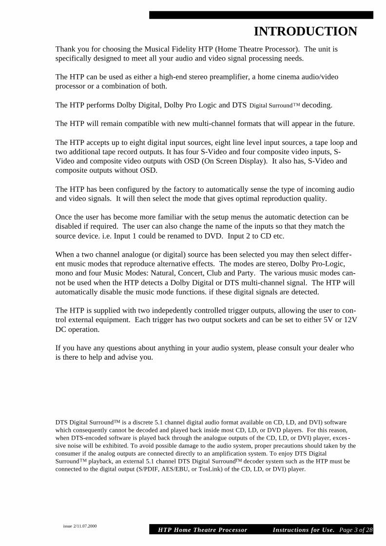
INTRODUCTIONThank you for choosing the Musical Fidelity HTP (Home Theatre Processor). The unit is specifically designed to meet all your audio and video signal processing needs.
The HTP can be used as either a high-end stereo preamplifier, a home cinema audio/videoprocessor or a combination of both.
The HTP performs Dolby Digital, Dolby Pro Logic and DTS Digital SurroundTM decoding.
The HTP will remain compatible with new multi-channel formats that will appear in the future.
The HTP accepts up to eight digital input sources, eight line level input sources, a tape loop andtwo additional tape record outputs. It has four S-Video and four composite video inputs, S-Video and composite video outputs with OSD (On Screen Display). It also has, S-Video andcomposite outputs without OSD.
The HTP has been configured by the factory to automatically sense the type of incoming audioand video signals. It will then select the mode that gives optimal reproduction quality.
Once the user has become more familiar with the setup menus the automatic detection can bedisabled if required. The user can also change the name of the inputs so that they match thesource device. i.e. Input 1 could be renamed to DVD. Input 2 to CD etc.
When a two channel analogue (or digital) source has been selected you may then select differ-ent music modes that reproduce alternative effects. The modes are stereo, Dolby Pro-Logic,mono and four Music Modes: Natural, Concert, Club and Party. The various music modes can-not be used when the HTP detects a Dolby Digital or DTS multi-channel signal. The HTP willautomatically disable the music mode functions. if these digital signals are detected.
The HTP is supplied with two indepedently controlled trigger outputs, allowing the user to con-trol external equipment. Each trigger has two output sockets and can be set to either 5V or 12VDC operation.
If you have any questions about anything in your audio system, please consult your dealer whois there to help and advise you.
DTS Digital SurroundTM is a discrete 5.1 channel digital audio format available on CD, LD, and DVI) softwarewhich consequently cannot be decoded and played back inside most CD, LD, or DVD players. For this reason,when DTS-encoded software is played back through the analogue outputs of the CD, LD, or DVI) player, exces -sive noise will be exhibited. To avoid possible damage to the audio system, proper precautions should taken by theconsumer if the analog outputs are connected directly to an amplification system. To enjoy DTS DigitalSurroundTM playback, an external 5.1 channel DTS Digital SurroundTM decoder system such as the HTP must beconnected to the digital output (S/PDIF, AES/EBU, or TosLink) of the CD, LD, or DVI) player.
issue 2/11.07.2000
HTP Home Theatre Processor Instructions for Use. Page 4 of 28
SAFETY INFORMATION
IMPORTANT!
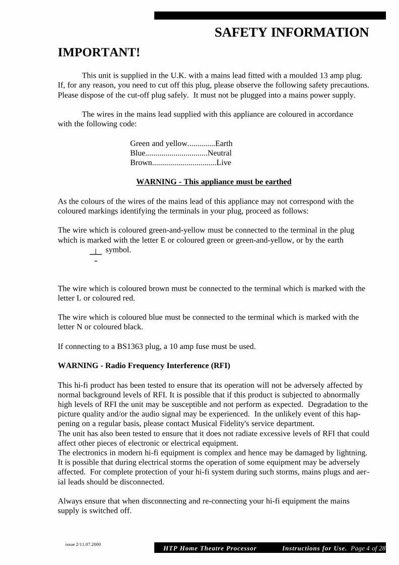
This unit is supplied in the U.K. with a mains lead fitted with a moulded 13 amp plug.If, for any reason, you need to cut off this plug, please observe the following safety precautions.Please dispose of the cut-off plug safely. It must not be plugged into a mains power supply.
The wires in the mains lead supplied with this appliance are coloured in accordancewith the following code:
Green and yellow..............Earth Blue...............................Neutral Brown................................Live
WARNING - This appliance must be earthed
As the colours of the wires of the mains lead of this appliance may not correspond with thecoloured markings identifying the terminals in your plug, proceed as follows:
The wire which is coloured green-and-yellow must be connected to the terminal in the plugwhich is marked with the letter E or coloured green or green-and-yellow, or by the earth
symbol.
The wire which is coloured brown must be connected to the terminal which is marked with theletter L or coloured red.
The wire which is coloured blue must be connected to the terminal which is marked with theletter N or coloured black.
If connecting to a BS1363 plug, a 10 amp fuse must be used.
WARNING - Radio Frequency Interference (RFI)
This hi-fi product has been tested to ensure that its operation will not be adversely affected bynormal background levels of RFI. It is possible that if this product is subjected to abnormallyhigh levels of RFI the unit may be susceptible and not perform as expected. Degradation to thepicture quality and/or the audio signal may be experienced. In the unlikely event of this hap-pening on a regular basis, please contact Musical Fidelity's service department.The unit has also been tested to ensure that it does not radiate excessive levels of RFI that couldaffect other pieces of electronic or electrical equipment.The electronics in modern hi-fi equipment is complex and hence may be damaged by lightning.It is possible that during electrical storms the operation of some equipment may be adverselyaffected. For complete protection of your hi-fi system during such storms, mains plugs and aer-ial leads should be disconnected.
Always ensure that when disconnecting and re-connecting your hi-fi equipment the mains supply is switched off.
issue 2/11.07.2000
HTP Home Theatre Processor Instructions for Use. Page 5 of 28
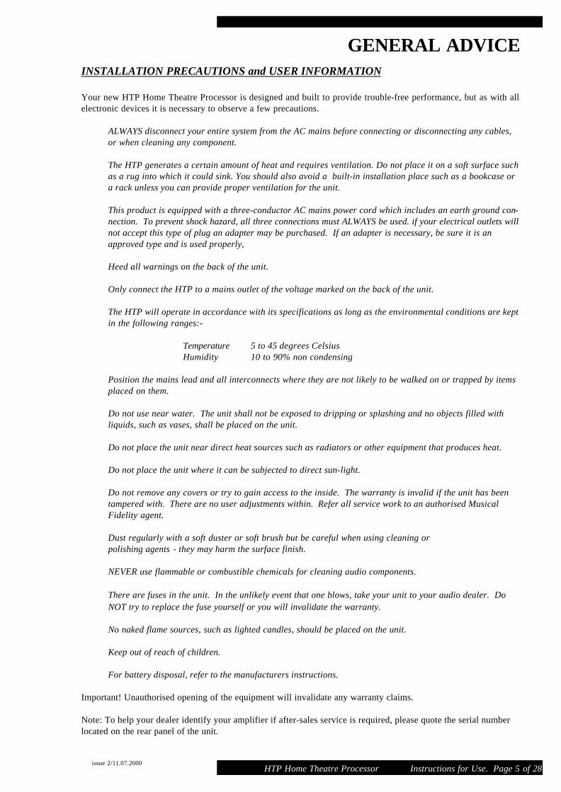
GENERAL ADVICEINSTALLATION PRECAUTIONS and USER INFORMATION
Your new HTP Home Theatre Processor is designed and built to provide trouble-free performance, but as with allelectronic devices it is necessary to observe a few precautions.
ALWAYS disconnect your entire system from the AC mains before connecting or disconnecting any cables,or when cleaning any component.
The HTP generates a certain amount of heat and requires ventilation. Do not place it on a soft surface suchas a rug into which it could sink. You should also avoid a built-in installation place such as a bookcase ora rack unless you can provide proper ventilation for the unit.
This product is equipped with a three-conductor AC mains power cord which includes an earth ground con-nection. To prevent shock hazard, all three connections must ALWAYS be used. if your electrical outlets willnot accept this type of plug an adapter may be purchased. If an adapter is necessary, be sure it is anapproved type and is used properly,
Heed all warnings on the back of the unit.
Only connect the HTP to a mains outlet of the voltage marked on the back of the unit.
The HTP will operate in accordance with its specifications as long as the environmental conditions are keptin the following ranges:-
Temperature 5 to 45 degrees CelsiusHumidity 10 to 90% non condensing
Position the mains lead and all interconnects where they are not likely to be walked on or trapped by itemsplaced on them.
Do not use near water. The unit shall not be exposed to dripping or splashing and no objects filled withliquids, such as vases, shall be placed on the unit.
Do not place the unit near direct heat sources such as radiators or other equipment that produces heat.
Do not place the unit where it can be subjected to direct sun-light.
Do not remove any covers or try to gain access to the inside. The warranty is invalid if the unit has beentampered with. There are no user adjustments within. Refer all service work to an authorised MusicalFidelity agent.
Dust regularly with a soft duster or soft brush but be careful when using cleaning or polishing agents - they may harm the surface finish.
NEVER use flammable or combustible chemicals for cleaning audio components.
There are fuses in the unit. In the unlikely event that one blows, take your unit to your audio dealer. DoNOT try to replace the fuse yourself or you will invalidate the warranty.
No naked flame sources, such as lighted candles, should be placed on the unit.
Keep out of reach of children.
For battery disposal, refer to the manufacturers instructions.
Important! Unauthorised opening of the equipment will invalidate any warranty claims.
Note: To help your dealer identify your amplifier if after-sales service is required, please quote the serial numberlocated on the rear panel of the unit.
issue 2/11.07.2000
HTP Home Theatre Processor Instructions for Use. Page 6 of 28
CONNECTIONS AND FACILITIES
issue 2/11.07.2000
AUDIO INPUTS
OPTICALDIGITALINPUTS
OPTICALDIGITALOUTPUT
OUT 2TAPE
COAXIALDIGITAL OUTPUT
TAPEOUT 1 321TAPE
IN
COAXIALDIGITAL INPUTS
MANUFACTURED IN ENGLAND
BY MUSICAL FIDELITY
87654 OPTIONSAUDIO OUTPUTSC
SLSL
R RS
LBAH
WR RB
COMPOSITE
TRIGGERS 2TRIGGERS 1
CAUTIONMOUNT UNIT ON SOLID SURFACE. DO NOT REMOVE SCREWS OR COVERS UNDER ANY CIRCUMSTANCES. NO USER SERVICEABLE COMPONENTS INSIDE. REFER SERVICING TO QUALIFIED ENGINEER. SEE OWNERS MANUAL FOR FURTHER INFORMATION.
POWER CONSUMPTION 40W
AA0
12v
5v
B12v
0
5v
B
WITHOUT OSD
VIDEO OUTPUTS
MUSICAL FIDELITYHTP HOME THEATRE
PROCESSOR
VIDEO INPUTS
21 3 4
'S' VIDEO
THIS PRODUCT COMPLIES WITH DHHS RULES 21 CFRCHAPTER 1, SUBCHAPTER J, PART 1040 AT DATE OFMANUFACTURE.THIS PRODUCT COMPLIES WITH PART 15 OF THE FCCRULES. OPERATION IS SUBJECT TO TWO CONDITIONS:1 THIS DEVICE MAY NOT CAUSE HARMFUL HARMFUL INTERFERENCE, AND2 THIS DEVICE MUST EXCEPT ANY INTERFERENCE RECIEVED INCLUDING INTERFERENCE THAT MAY CAUSE UNDESIRED OPERATION.
WITH OSD
10 11 12 13 14 15 16 17 18 19 20
21 22 23 24 25 26 27 28 29 30 31
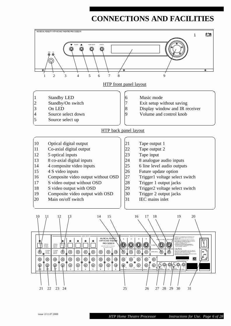
1 Standby LED2 Standby/On switch3 On LED4 Source select down5 Source select up
10 Optical digital output11 Co-axial digital output12 5 optical inputs13 8 co-axial digital inputs14 4 composite video inputs15 4 S video inputs16 Composite video output without OSD17 S video output without OSD18 S video output with OSD19 Composite video output with OSD20 Main on/off switch
21 Tape output 122 Tape output 223 Tape input24 8 analogue audio inputs25 6 line level audio outputs26 Future update option27 Trigger1 voltage select switch28 Trigger 1 output jacks29 Trigger2 voltage select switch30 Trigger 2 output jacks31 IEC mains inlet
MUSICAL FIDELITY HTP HOME THEATRE PROCESSOR
ONSTBY
MUSIC MODESOURCE CANCEL
1 2 3 4 5 6 7 8 9
HTP back panel layout
HTP front panel layout
6 Music mode 7 Exit setup without saving8 Display window and IR receiver9 Volume and control knob
1

HTP Home Theatre Processor Instructions for Use. Page 7 of 28
REMOTE CONTROL
issue 2/11.07.2000
1 2
654
7 8
OK
X
TRIMCONTROL
SURROUNDSUB
WOOFER
STATUS DISPLAY LATENIGHT
TAPEMONITOR
MUSICAL FIDELITYHTP
STANDBY
+ +
MM
TA
M
3
STANDBY used to switch the unit from standby to on andfrom on back into standby.
DIRECT ACCESS INPUT BUTTONS Use buttons 1 to 8and Tape to directly select the required input.
Used to scroll the different available music modes.
Used to enter and leave the set-up menu.
Use whilst navigating the set-up menus.
During normal operation the left and right arrows are used toincrease or decrease the input channel number selected.In set up mode, they are used when navigating the menus
During normal operation the up and down arrows are used toincrease or decrease the volume.In set up mode they are used, when navigating the menus
Use to exit setup at any time WITHOUT saving anychanges you have made.
Use to mute and un-mute the audio outputs of the HTP
Use to temporarily trim the level of the surround speakers.
Use to temporarily trim the level of the subwoofer.
Use to select and de-select tape input for tape monitoring.
Use to activate Late Night function.
Use to dim the display or return to normal brightness.
Use to display (only when OSD is active) status of theincoming audio and video signals.
REMOTE CONTROL
The following should be noted when operating the HTP using the remote control. The Infra Red receiver is located behind the window for the display on the front panel. It is important to ensure that when operating theremote control, the line-of-sight from the remote to the infra red receiver is not obstructed.
- Point the remote control (transmitter) towards the front panel display window on the HTP.
- Visual contact must exist between the transmitter and receiver.
- If the range of the remote control decreases dramatically, replace the batteries with new ones. (dispose of old batteries as per the manufacturers instructions)
- For your convenience MENU, OK, MUTE, EXIT and the cursor keys are all back lit. If any one of thesebuttons are pressed, all of these buttons will light up.

HTP Home Theatre Processor Instructions for Use. Page 8 of 28
AUDIO CONNECTIONSANALOGUE INPUTS 1…8
Connect the L and R audio output cables of any analogue devices to these sockets. Always connect these inputs,even when you are going to listen only via digital inputs (such sources as DVD or CD players). This ensures thatthere is always a signal at the tape record outputs.
The signal coming from any selected ANALOGUE audio input is fed through an A/D converter that turns the ana-logue signal into digital form (A/D = Analogue to Digital). The signal is now ready for Dolby Pro Logic decodingor post-processing with Music Modes. Then the signal is fed to D/A converter and to 5.1 Channel outputs
TAPE INPUT/OUTPUT
These inputs are suitable for all types of tape recorders, including three-head types, which allow you to monitor thesignal from the tape at the same time it is being recorded. Connect a set of interconnects from the TAPE REC out-put sockets of the preamp to the LINE IN or RECORD IN sockets of your tape recorder. Connect a second set ofcables from the TAPE PLAY input sockets to the LINE OUT or PLAY OUT sockets of your tape recorder.
Using the TAPE loop you can monitor the level and quality of the recording, at the same time as the recordingtakes place. You can also use it for connecting external devices (such as an equaliser) to the signal path. Note: Ifyou use an equaliser you must bypass it when listening to a Dolby surround source being decoded by DolbyProLogic.
Any ANALOGUE stereo source you have selected on the HTP will be automatically fed to the TAPE REC outputsockets for recording. You cannot make a recording from a source that is connected to the digital inputs.
RECORD OUTPUTS 1…2
The REC outputs carry the signal from the currently selected ANALOGUE stereo source device (except the sourceconnected to the TAPE PLAY input). You can connect these outputs to the inputs of any recording device. Thesignal can also be used in a multi-room set-up to feed power amplifiers in other rooms.
5.1 CHANNEL OUTPUTS (LEFT FRONT, RIGHT FRONT, LEFT SURROUND, RIGHT SURROUND CEN-TRE AND SUBWOOFER)
Connect these outputs to the line inputs of your power amplifiers. The SUB output is normally fed to the low-levelLine Input of an active subwoofer. Alternatively it may feed a separate power amplifier and a passive subwoofer.The option outputs are reserved for future surround formats.
COAXIAL DIGITAL AUDIO INPUTS 1…8
Connect the coaxial digital output cables from your source devices to these inputs.
OPTICAL DIGITAL AUDIO INPUTS 1...5
Connect the optical digital output cables from your source devices to these inputs.
PLEASE NOTE. It is possible to connect both optical and coaxial digital cables to inputs 1 through to 5. This isnot reccomended but if you choose to connect both cables, the HTP will use the optical source.
OPTICAL DIGITAL OUTPUT
Connect the optical input of your digital recorder to the DIGITAL output. The selected digital source is fed to thisoutput in digital format.
COAXIAL DIGITAL OUTPUT
Connect the coaxial input of your digital recorder to the DIGITAL output. The selected digital source is fed to thisoutput in digital format.
issue 2/11.07.2000

HTP Home Theatre Processor Instructions for Use. Page 9 of 28
VIDEO CONNECTIONSCOMPOSITE VIDEO INPUTS 1…4
Connect the composite video output cables coming from your video sources to these inputs.
The composite video signal is selected from the input signals, and then fed to the composite video outputs.
Note: Take care to use the same number input for both the video and audio connections from the source device.i.e. DVD player:- video to video input 1 and the digital audio of the same DVD player to either the optical orcoaxial digital input 1
COMPOSITE VIDEO OUTPUTS
There are two composite video outputs. Both will display the selected source on the display device i.e. TV or projector. Only one will have the On Screen Display information.
Connect either Composite Video output to your display device .
On Screen Display information, is only output to the COMPOSITE VIDEO OUTPUT WITH OSD.
S-VIDEO INPUTS 1…4
Connect the S-Video output cables from your video sources to these inputs.
Note: Take care to use the same number input for both the video and audio connections from the source device.
S-Video signals are of higher quality than Composite Video signals. If you have a source device with S-Video outputs, we recommend you to use them together with the S-Video inputs on your display device. S-Video inputsare automatically down-mixed, to feed the Composite Video outputs for displays that are without S-Video inputs.
S-VIDEO OUTPUT
There are two S-Video outputs. Both will display the selected source on the display device. Only one will havethe On Screen Display information.
Connect either S-Video output to your display device.
On Screen Display information is only output to S- VIDEO OUTPUT WITH OSD.
PLEASE NOTE:-
Do not connect a composite video signal input to the HTP (i.e. from a DVD player) and then connect the output ofthe HTP to the display device using S-Video.
issue 2/11.07.2000

HTP Home Theatre Processor Instructions for Use. Page 10 of 28
TRIGGER CONNECTIONSREMOTE TRIGGER OUTPUTS 1and 2
There are two completely separate trigger circuits. Trigger 1 and Trigger 2. They both have two output sockets.
Both trigger 1 and trigger 2 can be selected for either 5VDC or 12VDC operation. Changing the voltage is doneby the two switches located on the back panel, one for trigger 1 and one for trigger 2. If the switch is set to thecentre position the trigger voltage is disabled.
The maximum current from each trigger socket is limited to 120mA for 12V operation and 50mA for 5V.
Connection to the triggers is made via a 3.5mm mono jack plug.
TRIGGER outputs can be programmed to operate under various user controlled conditions (see trigger menu sec-tion page 18).
CAUTION: ALWAYS DISCONNECT THE UNIT FROM THE MAINS SUPPLY BEFORE CONNECTINGOR DISCONNECTING THE TRIGGERS!
issue 2/11.07.2000

HTP Home Theatre Processor Instructions for Use. Page 11 of 28
USEFUL INFORMATION
issue 2/11.07.2000
CABLESUse 75 ohm cables for all composite video connections and for all coaxial digital audio connections.To comply with EMC regulations all cables must be less than 3M in length. We reccomend that all cable lengthsare kept to a minimum.
MAINS SWITCHEnsure that all the HTP is switched to standby before operating the mains switch.
FUNCTIONS NOT AVAILABLE VIA FRONT PANELThe functions that cannot be accessed from the front panel are:- late night mode, dimming the front panel display,level trimming of the sub-woofer and surround speakers, and tape monitor input.
ON SCREEN DISPLAY (OSD)
IMPORTANT NOTEThe OSD will only work if the TV screen is connected to either the Composite, or S video output with OSD. TheOSD output (in the display set-up sub-menu) must also be set to the same output as you are using. i.e. SVideo orComposite. (SEE PAGE 18)
OSD SWITCHED OFF. Please be sure that the TV system is connected to the correct output and that OSD isenabled in the display set-up menu. The unit is configured by the factory so that OSD is enabled on both compos-ite and S video outputs. If the OSD has been switched off by mistake, the display set-up menu can be configuredusing the HTP front panel display.
PAL/NTSCThe HTP supports PAL and NTSC TV systems. Please ensure that this is set to the correct setting using theDisplay setup menu.
DOLBY DIGITAL / 5.1The front panel display and the OSD provides information concerning the type of audio signal that is beingreceived. When the Dolby D is displayed it will be followed by a series of numbers. The Dolby D indicates that aDolby Digital signal is being received and the numbers indicate which audio channels are being decoded. Pleasenote that various formats are possible, including 2/0, 3/0, 3/2 and 3/2.1. If Dolby D 2/0 is displayed it means thatalthough the incoming signal is a Dolby Digital signal, the format is only front left and right. If Dolby D 3/2.1 isdisplayed it means that you are receiving a full 5.1 Dolby Digital encoded signal where the ‘3’ represents frontleft, front right and centre, the ‘2’ represents left surround and right surround and the ‘1’ represents the LFE chan-nel.
DTS 5.1The same format is used for displaying the incoming DTS signal as is used for the Dolby Digital, except DTS willbe displayed instead of Dolby D
COMPOSITE VIDEO/S-VIDEOThe HTP will convert an S-Video input to a composite video output but not vica versa. To avoid any possible con-fusion we reccomend to use the same video standard for both inputs and outputs.
LFE (LOW FREQUENCY EFFECT)The LFE channel is a separate channel, created by the film sound engineer, with a limited low frequency rangeand is reproduced via the sub woofer.
SUB WOOFERThe subwoofer signal is created by mixing the LFE channel and the bass signals, from any of the speakers thathave been set to small.
If there is no subwoofer connected to the system, the LFE channel and the other channels bass will be directed tospeakers that can handle the signals. This is normally the main front speakers.

BASIC OPERATION
issue 2/11.07.2000 HTP Home Theatre Processor Instructions for Use. Page 12 of 28
mains switch
standby/on
input select
changing the volume
tape
music modes
menu button
OK/exit
mute
trim controlssubwoofer and sur-round
status
The mains switch is situated in the back of the unit. The unit is designed to be leftswitched on at all times. We do however recommend switching the unit off, with thisswitch, if the HTP is not going to be used for a long time i.e. 2/3 weeks. Ensure allthe HTP is switched to standby before turning the HTP on or off with the mainsswitch.
If the orange LED is lit on the front panel the unit is in standby mode. Press eitherthe red standby button on the remote control or the standby/on button on the frontpanel (located below the LEDs). and the unit will turn on.. The blue LED on thefront panel will light and the display will illuminate. If the unit is on, press either thestandby button on the remote or the front panel to switch the unit back into standby.
Please note:-When the unit is switched to standby (orange LED lit) video from the last selectedsource is still passed through the unit.
On the remote control use buttons 1 to 8 to directly select the desired input, or usethe left and right arrow keys to increment or decrement the input channel number.Alternatively you may use the source down and up buttons on the front panel.
Use either the volume/control knob on the front panel or the up and down buttons onthe remote control.
The tape button is used to select tape input.
Each press of the music mode button will scroll the different available music modes.Please note some options in this function will be disabled if a Dolby Digital or DTSmulti-channel signal is detected. See page 19 & 20 for more information on themusic modes.
Pressing the menu button enters the set-up menu. Detailed explanation of the set-upmenu starts on page 14
Both buttons are used whilst navigating the set-up menus
To MUTE the HTP press mute once, mute will be displayed on the front panel dis-play and also on the TV if OSD is active. To un-mute the unit, press mute again, orincrease the volume using either the remote control or the volume control.
Use these buttons to trim the level of the subwoofer and or the surround speakers.Please note. These setting will be reset to 0 when the unit is switched into standby.They are only intended for slight changes that may be required when different soundtracks are being played. If permanent setting are required use the level set-up menu.
Press the status button and (provided that OSD is enabled) the TV will display the current input that is selected and the status of the audio/video signals that the HTP isreceiving.

HTP Home Theatre Processor Instructions for Use. Page 13 of 28
BASIC OPERATION
Press the display button to dim the display. This is especially useful if you are watchingthe screen in a darkened room. Press the button again to return the display to normalbrightness.
This button activates the Late Night function which reduces the dynamic range for quieterlistening. The soundtrack is compressed so that all details are audible even at low listen-ing levels, but loud sounds are reduced in volume. Note: This function works only withDolby Digital sources.
This button selects the tape input for tape monitoring. Even if an alternative input isselected (i.e. input 1 to 8) tape monitor remains active. To switch off tape monitor pressthe button again.
Six buttons on the remote control are used to navigate through the HTP’s on screen dis-play (OSD) menu system: menu, OK,EXIT and the 4 compass keys.
You can also operate the menus from the front panel. The volume/control knob and theCancel button are all that are required.
Note that the front panel display of the HTP shows the menu that is ready to be selected,this is the same menu that is high lighted on the OSD. Entering setup provides access tothe six different menus listed below:-
TONE CONTROLSLEVEL SETUPDELAY SETUPSPEAKER SETUPSOURCE SETUPDISPLAY SETUP TRIGGER SETUP
Many of the settings in the above menus can have significant impact on the performanceand functionality of the system. Please read this manual fully and ensure you understandthe implications of the changes you are about to make, before changing anything.
issue 2/11.07.2000
display
late night
tape monitor
using the setupmenu system
Caution required
HTP Home Theatre Processor Instructions for Use. Page 14 of 28
SETUP MENU via REMOTE CONTROL
issue 2/11.07.2000
To enter the main menu using the remote control, push the MENU button. The setupmenu will be displayed on the TV screen (as long as OSD is switched on) The mainmenu options will also be displayed on the front panel display (only 2 lines of dis-play)
By pressing the up and down arrow keys the different options can be selected.
When the front panel display shows the required option or the OSD cursor indicatesthe required option press the OK button. You will now be into the selected sub-menu.
Press the up and down arrow keys to select the various options in the sub-menu.Once the required sub-menu is found press either the left or right arrow key to adjustthe settings.
Now press the up and down arrow keys to select the next option in the same sub-menu or exit. Press Ok to accept the choice.
At any time during the set-up mode, pressing the MENU button on the remote con-trol will save the changes and exit set-up mode.
Once in the menu system you can exit without saving any of the changes you havemade at any time by pressing the EXIT button on the remote control.
to select a menuitem
to change a submenu item
to save changes
to "escape" or "can-cel" or exit

HTP Home Theatre Processor Instructions for Use. Page 15 of 28
SETUP MENU via FRONT PANEL
issue 2/11.07.2000
To enter the main menu using the buttons on the front panel, push the rotary controlthe setup menu will be displayed on the TV screen (as long as OSD is switched on)The main menu options will also be displayed on the front panel display (only 2 linesof display)
Keep pressing the volume/control knob until the correct menu is displayed. Whenthe display shows the required option, or the OSD cursor indicates the correct option,turn the volume/control knob one position to either the left or the right. You willnow be into the selected sub-menu
Pressing the volume/control button will now scroll the various options in the sub-menu. Once the required sub-menu is found turn the control knob 1 position to eitherthe left or right to change the settings. When the required setting has been selectedpress the control knob, this will select the next option in the same sub-menu.
If you want to exit and save the changes, keep pressing the control knob until exit ishighlighted then turn the knob 1 position left or right.
Once in the menu system, you can at any time, press the CANCEL button on thefront panel to exit the set-up menus without saving any of the changes you havemade.
to select a menuitem
to change a menuItem
to save changes
to "escape" or "can-cel" or exit

HTP Home Theatre Processor Instructions for Use. Page 16 of 28
TONE CONTROLS, LEVEL & DELAY SETUPTONE CONTROLS. Use the tone controls to adjust the bass and treble to thedesired settings. The levels set will be stored until they are changed again.
Use the cursor left and right keys to increase or decrease the level of the bass. Eachpress of the left or right cursor key will change the level up or down by 1dB.
Use the cursor left and right keys to increase or decrease the level of the treble.Each press of the left or right cursor key will change the level up or down by 1dB.
issue 2/11.07.2000
DELAY SETUP
CENTRERIGHT SURROUNDLEFT SURROUND
LEVEL SETUP
LEFTCENTRERIGHTRIGHT SURROUNDLEFT SURROUNDSUB WOOFER
LFE CHANNEL
TEST SIGNAL
TONE CONTROLS
BASS
TREBLE
LEVEL SETUP. Used to set the listening level of the individual speakers. Ensurethe master volume is set loud enough to listen to the source or to approx. -20dB ifyou are going to use the test signal before entering the level setup procedure.
Each speaker can be adjusted between -10 and +15dB in steps of 1dB
LFE explanation (see page 11) The LFE channel can be adjusted between -10 and0dB
This switches on the Noise Test signal. (Ensure that the volume control is set toapprox. -20dB before activating the test signal) A broadband noise is sent first tothe Left front channel for a few seconds, then to the Centre channel and so onthrough the other channels. Move the cursor to the speaker that needs adjusting.Increase or decrease the level with the left or right arrow keys and the noise willmove to that channel and the change will be implemented. Each press of the left orright cursor key changes the level up or down by 1dB. While the level is beingadjusted, the noise signal remains directed to that channel and it will only move tothe next channel after the adjustment has been completed.
DELAY SETUP. This is used to set the delay of the centre, right surround and leftsurround speakers. SEE PAGE 21 for more information about setting the delays.
The centre channel can be adjusted between 0 and 5mS. The surround channels can be adjusted between 0 and 15mS.

HTP Home Theatre Processor Instructions for Use. Page 17 of 28
SPEAKER & SOURCE SETUP
issue 2/11.07.2000
SPEAKER SETUP
MAIN SPEAKERS
CENTRE SPEAKERS
SURROUND SPEAKERS
SUB WOOFER
SUB WOOFER FREQ.
BASS MIX
The HTP needs to know the size of the speakers being used in the system.The size is either large or small. A large speaker is one that can handlethe full low scale frequencies. (bass) Any bass signal that has been redi-rected away from a small speaker will be added to the LFE channel andreproduced in the subwoofer. If there is no sub woofer the LFE and theredirected signals (if there are any) will be added to the main front speak-ers.
The main speakers can be set to either small or large.
The centre speakers can be set to either small, large or no speaker.
The surround speakers can be set to either small, large or no speakers.
The options available for the subwoofer is yes or no
You can set the subwoofer crossover frequency between 40Hz to 140Hz.The crossover frequency defines the frequency below which the low fre-quency signal does not go to small speakers, but is redirected to largespeakers and/or a subwoofer
Bass Mix mode can be set to on or off. When it is on bass signals are sentboth to the "Large" loudspeakers and to the subwoofer channel. Thisallows more bass volume, provided large main loudspeakers are used. Ifset to off all the bass signals are sent to the subwoofer only.
SOURCE SETUP
SOURCE
TITLE
ANALOGUE SENSE
Source setup allows you to configure the 8 inputs for your personal taste.
Source, is the number of the input i.e. input 3,4 etc
Change the title of the input to meet your own requirements. Once thissub menu has been selected use the left and right arrow keys (or push thevolume/control knob) to select the characters to be changed. Then use theup/down keys (or turn the volume/control knob) to change the characters.
Different analogue sources have large variations in output voltage. Theanalogue input can be adjusted to help take account of these variations.Select +3dB for sources that are too quiet, and either -3 or -6dB forsources that are to loud.

TRIGGER SETUP
TRIGGER 1 SENSE
POLARITY
DELAY
DURATION
TRIGGER 2 SENSE
HTP Home Theatre Processor Instructions for Use. Page 18 of 28
DISPLAY and TRIGGER SETUP
issue 2/11.07.2000
DISPLAY SETUP
TV SYSTEM
SUPERIMPOSE
TEMPORARY DISPLAY
VIDEO FORMAT
OSD OUTPUT
OSD STYLE
Display setup allows you to set the parameters for the video section of theHTP
Use this sub-menu to select the TV operating system. This will be eitherPAL or NTSC. Many modern TVs will accept either format without prob-lems.
When using the OSD, you can choose whether you want to have the OSDinformation only, on the screen, or have it displayed superimposed on thepicture. To have OSD only, set superimpose to off. To have OSD dis-played superimposed on the picture, set superimpose to on.
The temporary display is the information that appears on the screen whenyou first turn on or change input channels. This can be set to full, simpleor off. Full will display all the audio and video information, simple willjust indicate the selected channel and off disables the function.
Normally set to auto. In this mode the HTP will automatically detect eitherS-Video or composite video inputs. If preferred this can be set specificallyfor S-Video or composite video.
Normally set to both. The OSD information can be sent to either, the com-posite outputs, the SVideo outputs , both,.or off. If you accidently turn offthe OSD you can select the display sub-menu using the front panel display to turn it back on.
You can select different colours for the OSD. This only applies if superimpose is turned off. Scroll between numbers 1 to 30 to see the dif-ferent colours.
Used to set the operating parameters of the triggers.
Sense sets the condition that will activate the trigger, this can be set topower on (i.e. when the unit is switched on from standby), it can also be setto activate when a particular input is selected or when the front panel display is dimmed.
Polarity sets the polarity of the trigger. When set to posit. the trigger out-puts a positive voltage when activated. It then returns to 0V when deactivated. When set to negat. the HTP outputs 0V when the trigger isactivated and returns to positive voltage when deactivated.
Delay sets the time delay between the trigger circuit being activated and thevoltage actually changing on the output socket. This can be set between nodelay up to 3 minutes.
Duration sets how long the trigger stays set. The duration can be setbetween 10mS up to 3 minutes in various steps or infinity, (i.e. it stays acti-vated until the sense condition changes).
Please Note, All the settings for TRIGGER 2 are the same as for TRIGGER 1.
HTP Home Theatre Processor Instructions for Use. Page 19 of 28
MUSIC MODES
issue 2/11.07.2000
SIGNAL TYPE MODE PROCESSINGOUTPUT FROM
SPEAKERS
Analogue signal Stereo Stereo L,R
Mono Mono C
Pro Logic Dolby Pro Logic L, R,C, LS, RS
Music Modes: (Natural, Concert, Club and Party)
Music Mode L, R, C, LS, RS
Dolby Digital 2.0 Stereo Stereo L,R
Mono Not applicable Not applicable
Pro Logic Dolby Pro Logic L, R,C, LS, RS
Music Modes: (Natural, Concert, Club and Party)
Not applicable Not applicable
PCM Stereo Stereo L,R
Mono Mono C
Pro Logic Dolby Pro Logic L, R,C, LS, RS
Music Modes: (Natural, Concert, Club and Party)
Music Mode L, R, C, LS, RS
Dolby Digital (excluding 2.0) Stereo Not applicable Not applicable
Mono Not applicable Not applicable
Pro Logic Not applicable Not applicable
Music Modes: (Natural, Concert, Club and Party)
Not applicable Not applicable
DTS 3/2 Stereo Not applicable Not applicable
Mono Not applicable Not applicable
Pro Logic Not applicable Not applicable
Music Modes: (Natural, Concert, Club and Party)
Not applicable Not applicable
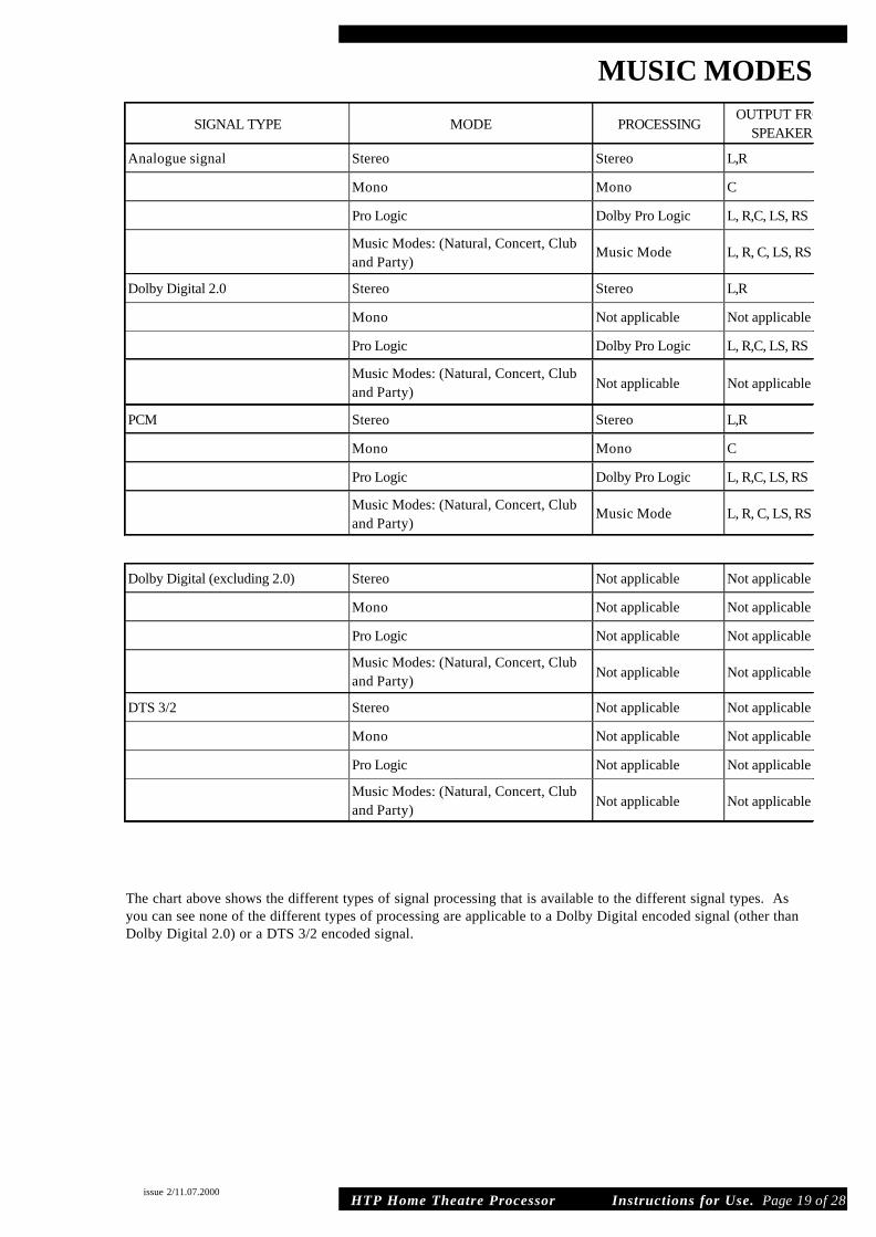
The chart above shows the different types of signal processing that is available to the different signal types. Asyou can see none of the different types of processing are applicable to a Dolby Digital encoded signal (other thanDolby Digital 2.0) or a DTS 3/2 encoded signal.

HTP Home Theatre Processor Instructions for Use. Page 20 of 28
DELAY SETUPDELAY SETUP
This is used to compensate for differing distances from the listening position of the various speakers. Ideally yourcentre speaker and your surround speakers will be closer to your listening position than the main left and rightspeakers. You can now adjust the delay to fine tune the system so that the sound from each speaker is heard atexactly the right time at the listening position.
The delay is calibrated in milli-seconds (mS) and is adjustable in 1mS steps. The centre channel can be adjustedover the range 0 - 5mS and the surround channels over the range 0 - 15mS.To convert the following distance measurements into mS use this rule:- 1metre= 3mS, or 1foot = 1mS
CENTRE DELAY:
Measure the distance from the listening position to the main left and right speakers. (eg. 5meters) Now measurethe distance from the listening position to the centre speaker (eg. 4 meters). Subtract one from the other (5-4=1)resulting with 1metre difference. The centre delay should therefore be set for 3mS.
Note: If the distance to the centre speaker is greater than the distance to the main left and right speakers then setthe delay to zero or move the speakers so that the centre is nearer to the listening position.
L & R SURROUND DELAY:
Remembering the distance measured previously from the listening position to the main left and right speakers,(5meters), now measure the distance from the listening position to the right surround speaker (eg. 2meters).Subtract one from the other (5-2=3) resulting with 3metre difference. The Right Surround delay should thereforebe set to 9mS.
Repeat this procedure for the left surround speaker.
Note: If the distance to either of the surround speakers is greater than the distance to the main left and right speak-ers then set it's delay to zero or move the surround speakers so that they are nearer to the listening position.
issue 2/11.07.2000

HTP Home Theatre Processor Instructions for Use. Page 21 of 28
MENUS AND SETTING OPTIONS
issue 2/11.07.2000
MAIN MENU
TONE CONTROLSLEVEL SETUPDELAY SETUPSPEAKER SETUPSOURCE SETUPDISPLAY SETUPTRIGGER SETUP
EXIT
DELAY SETUP
CENTRERIGHT SURROUNDLEFT SURROUND
EXIT
LEVEL SETUP
LEFTCENTRERIGHTRIGHT SURROUNDLEFT SURROUNDSUB WOOFERLFE CHANNELTEST SIGNAL
EXIT
TONE CONTROLS
BASS - - - - - - - -0 - - - - - - - -TREBLE - - - - - - -0 - - - - - - - -
EXIT
MAINMENU
TONE CON-TROLS
LEVELSETUP
DELAYSETUP
OPTIONS
Ok
Ok
Ok
Ok
Ok
Ok
Ok
Ok
OPTIONS
-10 - +15dB
-10 - +15dB
-10 - +15dB
-10 - +15dB
-10 - +15dB
-10 - +15dB
-10 - 0dB
On, Off
Ok
OPTIONS
-12 - +12 dB-12 - +12 dB
Ok
OPTIONS
0 -5 mS0 -15 mS0 -15 mS
Ok
STEPS OF
None
None
None
None
None
None
None
None
STEPS OF
1dB
1dB
1dB
1dB
1dB
1dB
1dB
STEPS OF
1dB
1dB
STEPS OF
1mS
1mS
1mS

HTP Home Theatre Processor Instructions for Use. Page 22 of 28
MENUS AND SETTING OPTIONS
issue 2/11.07.2000
SPEAKER SETUP
MAIN SPEAKERSCENTRE SPEAKERSSURROUND SPEAKERSSUB WOOFER
SUB WOOFER FREQ.BASS MIX
EXIT
DISPLAY SETUP
TV SYSTEMSUPERIMPOSETEMPORARY DISPLAYVIDEO FORMATOSD OUTPUTOSD STYLE
EXIT
TRIGGER SETUP
TRIGGER 1 SENSE
POLARITYDELAYDURATION
TRIGGER 2 SENSE
POLARITYDELAYDURATION
EXIT
SOURCE SETUP
SOURCETITLEANALOGUE SENSE
EXIT
SPEAKERSETUP
SOURCESETUP
DISPLAYSETUP
TRIGGERSETUP
OPTIONS
Small, Large, None
Small, Large, None
Small, Large, None
Yes, No
40 - 140Hz
Yes, No
Ok
OPTIONS
Source 1 to 8, Power on,Display Dim, Posit, Negat
No, 1sec to 3 mins
10mS to infin
Source 1 to 8, Power on,Display Dim, Posit, Negat
No, 1sec to 3 mins10mS to infin
Ok
OPTIONS
PAL/NTSC
Yes, No
Off, Simple, Full
Auto, SVideo, Compos,
Compos, Svideo, Both, Off
1 - 30
Ok
OPTIONS
1 - 8
7 characters long
-6 - +3dB
Ok
STEPS OF
10Hz
STEPS OF
3dB
STEPS OF
1
STEPS OF
Non Linear
Non Linear
Non Linear
Non Linear
TROUBLESHOOTING
issue 2/11.07.2000
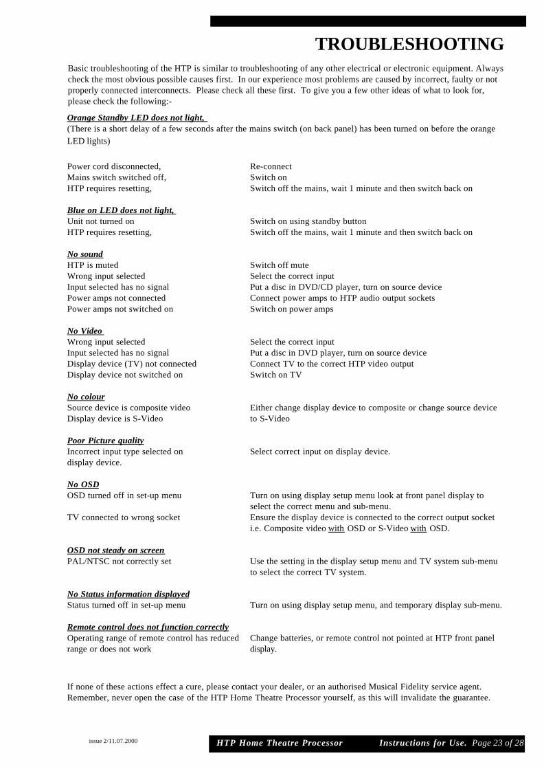
Basic troubleshooting of the HTP is similar to troubleshooting of any other electrical or electronic equipment. Alwayscheck the most obvious possible causes first. In our experience most problems are caused by incorrect, faulty or notproperly connected interconnects. Please check all these first. To give you a few other ideas of what to look for,please check the following:-
If none of these actions effect a cure, please contact your dealer, or an authorised Musical Fidelity service agent.Remember, never open the case of the HTP Home Theatre Processor yourself, as this will invalidate the guarantee.
HTP Home Theatre Processor Instructions for Use. Page 23 of 28
Orange Standby LED does not light, (There is a short delay of a few seconds after the mains switch (on back panel) has been turned on before the orangeLED lights)
Power cord disconnected, Re-connectMains switch switched off, Switch onHTP requires resetting, Switch off the mains, wait 1 minute and then switch back on
Blue on LED does not light, Unit not turned on Switch on using standby buttonHTP requires resetting, Switch off the mains, wait 1 minute and then switch back on
No soundHTP is muted Switch off muteWrong input selected Select the correct inputInput selected has no signal Put a disc in DVD/CD player, turn on source devicePower amps not connected Connect power amps to HTP audio output socketsPower amps not switched on Switch on power amps
No Video Wrong input selected Select the correct inputInput selected has no signal Put a disc in DVD player, turn on source deviceDisplay device (TV) not connected Connect TV to the correct HTP video outputDisplay device not switched on Switch on TV
No colourSource device is composite video Either change display device to composite or change source device Display device is S-Video to S-Video
Poor Picture qualityIncorrect input type selected on Select correct input on display device.display device.
No OSDOSD turned off in set-up menu Turn on using display setup menu look at front panel display to
select the correct menu and sub-menu. TV connected to wrong socket Ensure the display device is connected to the correct output socket
i.e. Composite video with OSD or S-Video with OSD.
OSD not steady on screenPAL/NTSC not correctly set Use the setting in the display setup menu and TV system sub-menu
to select the correct TV system.
No Status information displayedStatus turned off in set-up menu Turn on using display setup menu, and temporary display sub-menu.
Remote control does not function correctlyOperating range of remote control has reduced Change batteries, or remote control not pointed at HTP front panelrange or does not work display.

issue 2/11.07.2000
Audio analog inputs8 RCA (Line level),1tape loop
Audio analog outputs6 channels (left right, left surround, right surround, centre channel and subwoofer)2 tape outputs
Audio digital inputsCoaxial digital 8 Optical digital 5
Audio digital outputsCoaxial digital 1 Optical digital 1
Video inputsComposite 4SVideo 4
Video outputsComposite 2 (1 with OSD 1 without OSD)SVideo 2 (1 with OSD 1 without OSD)
Trigger outputs 4 (2+2)
Mains Inlet 3 pin IEC connector
HTP Home Theatre Processor Instructions for Use. Page 24 of 28
Musical Fidelity reserves the right to make improvements which may result in specification or feature changes without notice.
INPUT/OUTPUT CONNECTIONS
HTP
Home Theatre Processor

HTP Home Theatre Processor Instructions for Use. Page 25 of 28
SPECIFICATIONS
issue 2/11.07.2000
AUDIO SECTION
THD plus noise typically < 0.008% 20Hz - 20KHz ‘A’ weighted
Frequency response 20Hz - 20kHz +0dB -0.9dB
Sensitivity (for 1V RMS output) Line 220mV
Analogue Input impedance 10K
Tape input impedance 50K
Channel separation 100dB 20Hz - 20KHz
Output impedance (all analogue outputs) 50R
S/N ratio (ref 1V RMS) -85dB ‘A’ weighted
Maximum output voltage 10V rms 20Hz - 20KHz
VIDEO SECTION
Video input impedance (Composite RCA) 75RVideo input impedance (SVideo) Y = 75R C = 75R
Video output impedance (Composite RCA) 75RVideo output impedance (SVideo) Y = 75R C = 75R
TV Systems PAL or NTSC
TRIGGER OUTPUTSVoltage +5V or +12V (selected by switch on back panel)Max current +5V 50mA
+12V 120mA
Dimensions 440 x 95 x 400mm (W x H x D)Height includes feet, depth includes terminals
Weight 13 kg (un-boxed)
Power requirements 100/115/230V AC 50/60Hz(Factory preset)
Power consumption 40 watts (maximum)
Standard accessories Remote control handsetIEC type mains lead 4 x batteries (AAA, SUM-3, CR6)
Musical Fidelity reserves the right to make improvements which may result in specification or feature changes without notice.
HTP
Home Theatre Processor
HTP Home Theatre Processor Instructions for Use. Page 26 of 28
INDEX
ANALOGUE INPUTS · · · · · · · · · · · · · · · · · · · · · · · · · · · · · · 6, 8
ANALOGUE OUTPUTS · · · · · · · · · · · · · · · · · ·· · · · · · · · · · 6
ANALOG. SENS.· · · · · · · · · · · · · · · · · · · · · · · · · · · · · · · · · · 17
ARROW KEYS (COMPASS KEYS) · · · · · · · · · · ·· · · · · · · · 7
BASS MIX · · · · · · · · · · · · · · · · · · · · · · · · · · · · · · · · · ·· · · · 17
CABLES · · · · · · · · · · · · · · · · · · · · · · · · · · · · · · · · · · · · · · · · 11
CENTRE · · · · · · · · · · · · · · · · · · · · · · · · · · · · · ·· · · · · · · · · · 6
CLUB (MUSIC MODE) · · · · · · · · · · · · · · · · · · · · · · · · · · · · · 19
COAXIAL DIGITAL AUDIO INPUTS · · · · · · · · · · · · · · · · · 6, 8
COAXIAL DIGITAL AUDIO OUTPUT · · · · · · · · · · · · · · · · 6, 8
COMPOSITE VIDEO · · · · · · · · · · · · · · · · · · · · · · · · · · · · · · 11
COMPOSITE VIDEO INPUTS · · · · · · · · · · · · · · · · · · · · · · · 3, 6
COMPOSITE VIDEO OUTPUT (WITH OSD) · · · · · · · · · · · 3, 6
COMPOSITE VIDEO OUTPUT (WITHOUT OSD · · · · · · · · 3, 6
COMPRESS · · · · · · · · · · · · · · · · · · · · · · · · · · · · · · · · · · · · · · 13
CONCERT (MUSIC MODE) · · · · · · · · · · · · · · · · · · · · · · · · · 19
DELAY EXPLANATION · · · · · · · · · · · · · · · · · · · · · · · · · · · · 20
DELAY SETUP · · · · · · · · · · · · · · · · · · · · · · · · · · · · · · · · · · · 16, 20, 21
DIMENSIONS · · · · · · · · · · · · · · · · · · · · · · · · · · · · · · · · · · · · 25
DISPLAY BUTTON · · · · · · · · · · · · · · · · · · · · · · · · · · · · · · · · 7, 12
DISPLAY (FRONT PANEL) · · · · · · · · · · · · · · · · · · · · · · · · · 8
DISPLAY SETUP · · · · · · · · · · · · · · · · · · · · · · · · · · · · · · · · · 18, 22
DOLBY DIGITAL · · · · · · · · · · · · · · · · · · · · · · · · · · · · · · · · · 3, 11
DOLBY PRO LOGIC · · · · · · · · · · · · · · · · · · · · · · · · · · · · · · · 3, 19
DTS · · · · · · · · · · · · · · · · · · · · · · · · · · · · · · · · · · · · · · · · · · · · 3, 11
DURAT. · · · · · · · · · · · · · · · · · · · · · · · · · · · · · · · · · · · · · · · · · 18, 22
EXIT · · · · · · · · · · · · · · · · · · · · · · · · · · · · · · · · · · · · · · · · · · · 7, 14, 15
EXIT BUTTON · · · · · · · · · · · · · · · · · · · · · · · · · · · · · · · · · · · 6
FAULT FINDING · · · · · · · · · · · · · · · · · · · · · · · · · · · · · · · · · · 23
HUMIDITY · · · · · · · · · · · · · · · · · · · · · · · · · · · · · · · · · · · · · · 4
INPUT IMPEDANCE · · · · · · · · · · · · · · · · ·· · · · · · · · · · · · · 28
INPUT LEVEL · · · · · · · · · · · · · · · · · · · · · · · · · · · · · · · · · · · · 28
INPUT SELECT · · · · · · · · · · · · · · · · · · · · · · · · · · · · · · · · · · · 12
LARGE" SPEAKERS · · · · · · · · · · · · · · · · · · · · · · · · · · · · · · · 17
LATE NIGHT BUTTON · · · · · · · · · · · · · · · · · · · · · · · · · · · · · 7, 13
LEFT FRONT · · · · · · · · · · · · · · · · · · · · · · · · · · · · · · · · · · · · · 6
LEFT REAR · · · · · · · · · · · · · · · · · · · · · · · · · · · · · · · · · · · · · · 6
LEFT SURROUND · · · · · · · · · · · · · · · · · · · · · · · · · · · · · · · · 6
LEVEL SETUP · · · · · · · · · · · · · · · · · · · · · · · · · · · · · · · · · · · 16, 21
LEVEL TRIM KEYS · · · · · · · · · · · · · · · · · · · · ·· · · · · · · · · · 12
LFE (LOW FREQUENCY EFFECTS) · · · · · · · ·· · · · · · · · · · 11
LINE INPUTS · · · · · · · · · · · · · · · · · · · · · · · · · · · · · · · · · · · · 6
LINE OUT · · · · · · · · · · · · · · · · · · · · · · · · · · · · · · · · · · · · · · · 6
MAIN MENU · · · · · · · · · · · · · · · · · · · · · · · · · · · · · · · · · · · · · 13, 14, 15, 21
MAINS FUSE · · · · · · · · · · · · · · · · · · · · · · · · · · · · · · · · · · · · 4
MAINS LEAD · · · · · · · · · · · · · · · · · · · · · · · · · · · · · · · · · · · · 4
MAINS ON/OFF SWITCH · · · · · · · · · · · · · · · · ·· · · · · · · · · · 6, 11, 12
MAXIMUM INPUT LEVEL · · · · · · · · · · · · · · · · · · · · · · · · · 28
issue 2/11.07.2000
HTP Home Theatre Processor Instructions for Use. Page 27 of 28
INDEX
MAXIMUM OUTPUT LEVEL · · · · · · · · · · · · · · · · · · · · · · · 28
MENU BUTTON · · · · · · · · · · · · · · · · · · · · · · · · · · · · · · · · · · 7, 12, 14
MONO · · · · · · · · · · · · · · · · · · · · · · · · · · · · · · · · · · · · · · · · · · 19
MUSIC MODES · · · · · · · · · · · · · · · · · · · · · · · · · · · · · · · · · · · 3, 12
MUSIC MODES BUTTON · · · · · · · · · · · · · · · · · · · · · · · · · · 6, 7
MUTE/MUTE BUTTON · · · · · · · · · · · · · · · · · · · · · · · · · · · · 7, 12
NOISE TEST SIGNAL · · · · · · · · · · · · · · · · · · · · · · · · · · · · · 16
NTSC · · · · · · · · · · · · · · · · · · · · · · · · · · · · · · · · · · · · · · · · · · · 11, 18
OK/OK BUTTON · · · · · · · · · · · · · · · · · · · · · · · · · · · · · · · · · 7, 12, 14, 15
ON LED · · · · · · · · · · · · · · · · · · · · · · · · · · · · · · · · · · · · · · · · · 6
OPTICAL DIGITAL AUDIO INPUTS · · · · · · · · · · · · · · · · · · 6, 8
OPTICAL DIGITAL AUDIO OUTPUT · · · · · · · · · · · · · · · · · 6, 8
OSD (ON SCREEN DISPLAY) · · · · · · · · · · · · · · · · · · · · · · · 11, 18
OSD (STYLE) · · · · · · · · · · · · · · · · · · · · · · · · · · · · · · · · · · · · 18
OUTPUT IMPEDANCE · · · · · · · · · · · · · · · · · · · · · · · · · · · · 28
PAL · · · · · · · · · · · · · · · · · · · · · · · · · · · · · · · · · · · · · · · · · · · · 11, 18
PARTY (MUSIC MODE) · · · · · · · · · · · · · · · · · · · · · · · · · · · · 19
PCM · · · · · · · · · · · · · · · · · · · · · · · · · · · · · · · · · · · · · · · · · · · 19
POLARITY (TRIGGER) · · · · · · · · · · · · · · · · · · · · · · · · · · · · 18
POWER CONSUMPTION · · · · ·· · · · · · · · · · · · · · · · · · · · · · 28
POWER INLET · · · · · · · · · · · · · · · · · · · · · · · · · · · · · · · · · · 6
POWER SWITCH · · · · · · · · · · · · · · · · · · · · · · · · · · · · · · · · · 6
PRO LOGIC · · · · · · · · · · · · · · · · · · · · · · · · · · · · · · · · · · · · · 3, 19
RECORD OUTPUTS · · · · · · · · · · · · · · · · · · · · · · · · · · · · · · · 8
REMOTE CONTROL · · · · · · · · · · · · · · · · · · · · · · · · · · · · · · 7, 14
RFI (RADIO FREQUENCY INTERFERENCE) · · · · · · · · · · 4
RIGHT FRONT · · · · · · · · · · · · · · · · · · · · · · · · · · · · · · · · · · · 6
RIGHT SURROUND · · · · · · · · · · · · · · · · · · · · · · · · · · · · · · · 6
SAVE CHANGES · · · · · · · · · · · · · · · · · · · · · · · · · · · · · · · · · 14, 15
SETUP · · · · · · · · · · · · · · · · · · · · · · · · · · · · · · · · · · · · · · · · · · 12
SETUP BY FRONT PANEL BUTTONS · · · · · · · · · · · · · · · · 15
SETUP BY REMOTE CONTROL · · · · · · · · · · · · · · · · · · · · · 14
SIGNAL TO NOISE RATIO · · · · · · · · · · · · · · · · · · · · · · · · · 28
SMALL SPEAKERS · · · · · · · · · · · · · · · · · · · · · · · · · · · · · · · 17
SOURCE NAME · · · · · · · · · · · · · · · · · · · · · · · · · · · · · · · · · · 3, 17
SOURCE SELECT UP AND DOWN BUTTONS · · · · · · · · · 6
SOURCE SELECTION · · · · · · · · · · · · · · · · · · · · · · · · · · · · · 12
SOURCE SETUP · · · · · · · · · · · · · · · · · · · · · · · · · · · · · · · · · 17, 22
SPEAKER SETUP · · · ·· · · · · · · · · · · · · · · · · · ·· · · · · · · · · · 17, 22
SPECIFICATIONS · · · ·· · · · · · · · · · · · · · · · · · · · · · · · · · · · · 25
STANDBY BUTTON · · · ·· · · · · · · · · · · · · · · · · · · · · · · · · · · 7, 12
STANDBY LED · · · · · · · · · · · · · · · · · · · · · · · · · · · · · · · · · · · 6, 12
STANDBY MODE · · · · · · · · · · · · · · · · · · · · · · ·· · · · · · · · · · 12
STANDBY SWITCH · · · · · · · · · · · · · · · · · · · · · · · · · · · · · · · 6, 12
STATUS/STATUS BUTTON · · · · · · · · · · · · · · · ·· · · · · · · · · · 7, 12
STEREO · · · · · · · · · · · · · · · · · · · · · · · · · · · · · · · · · · · · · · · · · 19
SUBWOOFER · · · · · · · · · · · · · · · · · · · · · · · · · · · · · · · · · · · · 11, 17
SUBWOOFER TRIM BUTTONS · · · · · · · · · · · · · · · · · · · · · · 7, 12
issue 2/11.07.2000
HTP Home Theatre Processor Instructions for Use. Page 28 of 28
INDEXSUPERIMPOSE · · · · · · · · · · · · · · · · · · · · · · · · · · · · · · · · · · 18
SURROUND TRIM BUTTONS · · · · · · · · · · · · · · · · · · · · · · 7, 12
S-VIDEO · · · · · · · · · · · · · · · · · · · · · · · · · · · · · · · · · · · · · · · 11
S-VIDEO INPUTS · · · · · · · · · · · · · · · · · · · · · · · · · · · · · · · · 3, 6, 9
S-VIDEO OUTPUT (WITH OSD) · · · · · · · · · · · · · · · · · · · · 3, 6, 9
S-VIDEO OUTPUT (WITHOUT OSD · · · · · · · · · · · · · · · · · 3, 6, 9
TAPE INPUT/OUTPUT · · · · · · · · · · · · · · · · · · · · · · · · · · · · 6, 8
TAPE INPUT BUTTON · · · · · · · · · · · · · · ·· · · · · · · · · · · · · · 7
TAPE MONITOR BUTTON · · · · · · · · · · · · · · · · · · · · · · · · · 7
TAPE MONITOR INPUT · · · · · · · · · · · · · · · · · · · · · · · · · · · 13
TEMPERATURE · · · · · · · · · · · · · · · · · · · · · · · · · · · · · · · · · 4
TEMPORARY DISPLAY · · · · · · · · · · · · · · · · · · · · · · · · · · · 18
TEST SIGNAL · · · · · · · · · · · · · · · · · · · · · · · · · · · · · · · · · · · 16
TONE CONTROLS · · · ·· · · · · · · · · · · · · · · · · · · · · · · · · · · · 16, 21
TOTAL HARMONIC DISTORTION · · · · · · · · · · · · · · · · · · 28
TRIGGERS · · · · · · · · · · · · · · · · · · · · · · · · · · · · · · · · · · · · · · 3, 10, 18
TRIGGER 1 · · · · · · · · · · · · · · · · · · · · · · · · · · · · · · · · · · · · · · 10, 18
TRIGGER 2 · · · · ·· · · · · · · · · · · · · · · · · · · · · · · · · · · · · · · · · 10, 18
TRIGGER SETUP · · · · · · · · · · · · · · · · · · · · · · · · · · · · · · · · · 18, 22
TRIGGER VOLTAGE SELECT SWITCH · · · · ·· · · · · · · · · · 6, 10
TRIM+ AND TRIM- · · · · · · · · · · · · · · · · · · · · · · · · · · · · · · · 12
TROUBLE SHOOTING · · · · · · · · · · · · · · · · · · · · · · · · · · · · 23
UP, DOWN, RIGHT, LEFT KEYS · · · · · · · · · · ·· · · · · · · · · · 7, 14
VACUUM FLUORESCENT DISPLAY · · · · · · · · · · · · · · · · · 6
WEIGHT · · · · · · · · · · · · · · · · · · · · · · · · · · · · · · · · · · · · · · · · 28
VIDEO FORMAT · · · · · · · · · · · · · · · · · · · · · · · · · · · · · · · · · 18
VOL UP AND DOWN · · · · · · · · · · · · · · · · · · · · · ·· · · · · · · 12
VOLUME/CONTROL KNOB · · · · · · · · · · · · · · · · · · · · · · · · 6
issue 2/11.07.2000