Holistic Vehicle Simulation using Modelica – An ... · Holistic Vehicle Simulation using Modelica...
8
Holistic Vehicle Simulation using Modelica – An Application on Thermal Management and Operation Strategy for Electrified Vehicles Claude Bouvy Forschungsgesellschaft Kraftfahrwesen mbH Steinbachstraße 7, 52074 Aachen [email protected] Sidney Baltzer Peter Jeck Jörg Gissing Thomas Lichius Lutz Eckstein Institut für Kraftfahrzeuge – RWTH Aachen University, Aachen Steinbachstraße 7, 52074 Aachen [email protected] Abstract The increasing electrification of the drive train in the automotive environment leads to higher require- ments for automotive systems and their design. Therefore, a computer based methodology to support the engineer in the design phase of car concepts, components and control algorithms is desirable. All relevant sections of a vehicle development process, e.g. longitudinal and lateral dynamics, thermal man- agement or the power supply should be considered. Due to this necessity a new holistic vehicle library is developed at the Forschungsgesellschaft Kraftfahrwesen mbH Aachen (fka) and Institute of Automotive Engineering (ika) of RWTH Aachen University. The introduced holistic method is applied exemplarily on architecture with the traction battery as thermal storage to determine the potential of such a design on the overall efficiency and to analyse dif- ferent operational strategies. Keywords: thermal management; vehicle simulation; traction battery, electric vehicle, range extender, thermal storage, control strategy 1 Introduction Due to ecologic and economic reasons, the overall efficiency and the emissions, both local and global, of individual mobility have to be improved. An in- creased electrification of the drive train is currently being considered as a promising approach for reduc- ing both the energy demand and the emissions. However, an increased electrification of the drive train, i.e. replacing or partly substituting the internal combustion engine, implies the integration of new components as well as a higher number of energy conversion units. The augmented number of components, as well as their diverging requirements and operating condi- tions will clearly increase the complexity of electri- fied car architectures. On the thermal side for exam- ple, the integration of temperature sensitive compo- nents, e.g. lithium ion batteries, may imply more complex cooling circuit architectures, as the relevant operating temperatures clearly differ to those of an electric machine or an internal combustion engine. On a mechanical level for example, there are several possibilities to couple an internal combustion engine and an electric machine: e.g. parallel and serial hy- brids. Furthermore the increased efficiency of the electric machine compared to the internal combustion en- gine, will also increase the complexity of both the architecture and the operation strategies. For battery electric vehicles (BEV) for example, the cabin has to be heated by means of electric energy, as in general no or little waste heat is available at a sufficiently high temperature level. Thus, for highly electrified concepts the cabin heating will directly influence the drive train, the power net and the design of the con- trol strategies. To minimise the used electric energy heat pump systems and improved heating control strategies are possible alternatives (cf. e.g. [1]). The given examples clearly show that a strongly in- creased complexity has to be expected for the design phase of future cars. Currently an overall design ap- DOI Proceedings of the 9 th International Modelica Conference 263 10.3384/ecp12076263 September 3-5, 2012, Munich, Germany
Transcript of Holistic Vehicle Simulation using Modelica – An ... · Holistic Vehicle Simulation using Modelica...

Holistic Vehicle Simulation using Modelica – An Application on Thermal Management and Operation Strategy for Electrified Vehicles
Claude Bouvy Forschungsgesellschaft Kraftfahrwesen mbH
Steinbachstraße 7, 52074 Aachen [email protected]
Sidney Baltzer Peter Jeck Jörg Gissing Thomas Lichius Lutz Eckstein Institut für Kraftfahrzeuge – RWTH Aachen University, Aachen
Steinbachstraße 7, 52074 Aachen [email protected]
Abstract
The increasing electrification of the drive train in the automotive environment leads to higher require-ments for automotive systems and their design. Therefore, a computer based methodology to support the engineer in the design phase of car concepts, components and control algorithms is desirable. All relevant sections of a vehicle development process, e.g. longitudinal and lateral dynamics, thermal man-agement or the power supply should be considered. Due to this necessity a new holistic vehicle library is developed at the Forschungsgesellschaft Kraftfahrwesen mbH Aachen (fka) and Institute of Automotive Engineering (ika) of RWTH Aachen University. The introduced holistic method is applied exemplarily on architecture with the traction battery as thermal storage to determine the potential of such a design on the overall efficiency and to analyse dif-ferent operational strategies.
Keywords: thermal management; vehicle simulation; traction battery, electric vehicle, range extender, thermal storage, control strategy
1 Introduction
Due to ecologic and economic reasons, the overall efficiency and the emissions, both local and global, of individual mobility have to be improved. An in-creased electrification of the drive train is currently being considered as a promising approach for reduc-ing both the energy demand and the emissions. However, an increased electrification of the drive
train, i.e. replacing or partly substituting the internal combustion engine, implies the integration of new components as well as a higher number of energy conversion units.
The augmented number of components, as well as their diverging requirements and operating condi-tions will clearly increase the complexity of electri-fied car architectures. On the thermal side for exam-ple, the integration of temperature sensitive compo-nents, e.g. lithium ion batteries, may imply more complex cooling circuit architectures, as the relevant operating temperatures clearly differ to those of an electric machine or an internal combustion engine. On a mechanical level for example, there are several possibilities to couple an internal combustion engine and an electric machine: e.g. parallel and serial hy-brids.
Furthermore the increased efficiency of the electric machine compared to the internal combustion en-gine, will also increase the complexity of both the architecture and the operation strategies. For battery electric vehicles (BEV) for example, the cabin has to be heated by means of electric energy, as in general no or little waste heat is available at a sufficiently high temperature level. Thus, for highly electrified concepts the cabin heating will directly influence the drive train, the power net and the design of the con-trol strategies. To minimise the used electric energy heat pump systems and improved heating control strategies are possible alternatives (cf. e.g. [1]).
The given examples clearly show that a strongly in-creased complexity has to be expected for the design phase of future cars. Currently an overall design ap-
DOI Proceedings of the 9th International Modelica Conference 263 10.3384/ecp12076263 September 3-5, 2012, Munich, Germany

proach is missing. In general different and mostly incompatible tools are applied for different design tasks and the overall design process is strongly hier-archic. Up to now such a top-down approach was practicable, as the correlation of the energy flows was minor. In general the internal combustion en-gine, as the core energy conversion unit, implicated the design of most other units, e.g. the cooling cir-cuit.
Furthermore, the different energy forms, chemical, mechanical, electrical and thermal, are increasingly correlated for electrified car concepts. The higher complexity as well as the necessity of a holistic ap-proach requires new tools to support the engineer in the design process.
2 Library description
The holistic model library developed at Forschungsgesellschaft Kraftfahrwesen mbH Aachen (fka) and Institute of Automotive Engineering (ika) of RWTH Aachen University (cf. [2]) takes into consideration all energetic (mechanical, electrical, thermal and chemical) and logical (sensors, actors and control units) flows including dynamic boundary conditions (e.g. drive cycles, ambient conditions) of automotive concerns. It follows a layer based level approach. Basically the modeling library is struc-tured as illustrated in Fig. 1.
Fig. 1: The four level structure of the holistic tool
2.1 Base Level
At the lowest level generalized elements are imple-mented which can easily be adapted due to the object oriented modeling property of inheritance or instan-tiation. On the base level the following packages are implemented. All elements on that level are not computable and are combined later on the compo-nents level.
• ThermalLib • ElectricLib • MechanicLib • StateModelLib • Utilities
The ThermalLib contains all base classes of thermal concern. Based on a general volume element with generalized mass and energy balances and proper-ties, a fluid and a solid element are derived and used for all calculations. Secondly the geometric infor-mation of these elements is defined.
For a fluid element the dynamic momentum bal-ance is calculated. A variable modeling depth of pressure drop calculation method may be adapted by choosing a flow model. A heat transfer model calcu-lates the coefficient of heat transfer and provides the necessary interface to e.g. the surrounding ambient. For the solids variable geometries are implemented based on a solidElement, so that new models can easily be generated on the components level. This is illustrated in Fig. 1 where a standardized shell ele-ment is used for electric machine housing, the tube of a heat exchanger or a cylindrical battery cell.
The other packages contain e.g. voltage sources (ElectricLib), inertias (MechanicLib) or general mathematical functions (Utilities). The StateModelLib uses both a model based and a function based approach, wherein data of literature or specific measured fluids can be chosen.
For physical values thermal, fluid, electric and mechanical connectors are defined using the flow and stream properties. For the logical signals ex-pandable connectors are used.
Interfaces are provided, so that the library stays compatible with the Modelica Standard Library con-nectors (cf. [3], [4]) and the Vehicle Interface Li-brary (cf. [5]).
Baselevel
Componentlevel
Systemlevel
Overall levele.g. vehicle
Holistic vehicle simulation using Modelica –An application on thermal management and …
264 Proceedings of the 9th International Modelica Conference DOI September 3-5, 2012, Munich Germany 10.3384/ecp12076263

2.2 Component Level
At the components level a variable number of base elements are combined to generate models to a cho-sen level of design. At present the components level has the following structure:
• HydraulicComponents • DriveTrainComponents • PassengerCabinComponents
E.g. tubes, valves, heat exchangers or pumps are el-ements of the Hydraulic Components, whereas gears, clutches, electric machines, internal combustion en-gines or the traction battery are part of the DriveTrainComponents. The different kinds of car body types are integrated e.g. in the Passenger CabinComponents. All the components inherit from the lower base class level as described above. Fig. 2 demonstrates the approach of the library by the example of the traction battery. It consists of the electrical model, a thermal model and a Battery management system (BMS). All sub models are im-plemented as replaceable models. Depending on the issue to be investigated the level of detail may be chosen for the single models. However, for the de-tailed component design, e.g. the exact shape of the cooling duct of a battery pack, a strongly increased level of detail, i.e. a strongly discretised modelling of the coolant flow, is needed, to judge both the heat transfer and the pressure losses as Thermal model (cf. Fig. 2). For the electric model a modeling ap-proach using manufacture data map or a more de-tailed calculation on the chemical level may be cho-sen. The BMS may be simulated as a single Read-Only system or more intelligent systems including a control unit may be chosen. The single models are linked via standardized con-nectors. For sensor models expandable connectors of the Modelica Standard Library (cf. [3]) are used.
Fig. 2: Modeling approach of the traction battery
2.3 System
At the system level the interactions of energy and signal flow between all components are implement-ed. The thermal fluid part of the system level is ex-emplarily shown for the low temperature cooling circuit of a battery electric vehicle in Fig. 3:
Fig. 3: schematic diagram of a battery cooling circuit
Fig. 4 shows the respective exemplary Modelica model of the configuration, including electrical, thermal and logical signals.
Fig. 4: Examplary model of the battery circuit
2.4 Overall Level
The vehicle level combines all vehicle sub models such as the power train, the respective cooling cir-cuits, the power supply and the passenger cabin. Beside the global boundary conditions, such as the driving cycle, the route profile, ambient conditions
Battery simulation model
Sensor signals
Battery management
� ����� ���� �� �� ������
� �� ����� �������
� ���� �� ������� �����
Thermal model
� �������� �����
� ��� �������
� ���� ������ �����
Electrical model
� !������ �����
� !������ ������
� "������ ������ ��� �����
Ploss, cells
Tcells
Session 2C: Climate Systems I
DOI Proceedings of the 9th International Modelica Conference 265 10.3384/ecp12076263 September 3-5, 2012, Munich, Germany
or initial conditions a control block which consists of the driver and the ECU manages all concerns of con-trol.
Fig. 5: schematic view of the overall level
3 The traction battery as thermal storage for range extended vehicles
In this chapter an application example is given for the use of the holistic vehicle simulation model ap-proach.
A major challenge for electrified vehicles is to cover the heating demand for the passenger cabin in an efficient way. As stated in Bouvy et al., (cf. [6]) the application of a heat pump system in combination with a preheated traction battery as heat source pro-vides an efficient solution for passenger cabin heat-ing, leading to higher range. In most cases the heat losses of the battery and the thermal capacity are not high enough to cover the heat demand of the passen-ger cabin so the battery cools down. To avoid an un-derrun of a critical minimal cell temperature an addi-tional electric heater needs to be switched on so the overall energetic benefit is rather low. Regarding a range extended electric vehicle the waste heat of the internal combustion engine may, besides providing the heat for the passenger cabin, be used to reheat the battery. By this, the overall efficiency of this cogene-ration (i.e. producing heat and power) unit may be maximized. Bouvy et al. (cf. [7]) have shown the important benefit of a cogeneration unit on the effi-ciency of passenger cars.
3.1 System architectures
For this paper two system architectures are discussed for a BEV with a range extender unit.
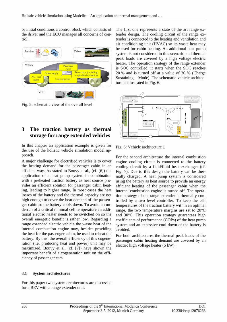
The first one represents a state of the art range ex-tender design. The cooling circuit of the range ex-tender is connected to the heating and ventilation and air conditioning unit (HVAC) so its waste heat may be used for cabin heating. An additional heat pump system is not considered in this scenario and thermal peak loads are covered by a high voltage electric heater. The operation strategy of the range extender is SOC controlled: it starts when the SOC reaches 20 % and is turned off at a value of 30 % (Charge Sustaining – Mode). The schematic vehicle architec-ture is illustrated in Fig. 6.
Fig. 6: Vehicle architecture 1
For the second architecture the internal combustion engine cooling circuit is connected to the battery cooling circuit by a fluid/fluid heat exchanger (cf. Fig. 7). Due to this design the battery can be ther-mally charged. A heat pump system is considered using the battery as heat source to provide an energy efficient heating of the passenger cabin when the internal combustion engine is turned off. The opera-tion strategy of the range extender is thermally con-trolled by a two level controller. To keep the cell temperatures of the traction battery within an optimal range, the two temperature margins are set to 20°C and 30°C. This operation strategy guarantees high coefficients of performance (COPs) of the heat pump system and an excessive cool down of the battery is avoided.
For both architectures the thermal peak loads of the passenger cabin heating demand are covered by an electric high voltage heater (5 kW).
Cooling circles
Power train (including longitudinal dynamics)
AC / heat pump
Passenger cabin
Power supply
Vehicle
Ambient Driver
VCU
Holistic vehicle simulation using Modelica –An application on thermal management and …
266 Proceedings of the 9th International Modelica Conference DOI September 3-5, 2012, Munich Germany 10.3384/ecp12076263

Fig. 7: Vehicle architecture 2
3.2 Simulation setup
In this analysis both layouts have a 44 kW rangetender unit, an 80 kW ASM electric engine and a lithium-ion-battery with a nominal capacity of 8.6 kWh (about 40 km BEV range determined on the basis of the NEDC). The data are chosen according to Hartmann and Renner (cf. [8]).
The defined vehicle has a cabin volume of 3a surrounding window surface of about 2 mdetermination of the cabin heat demand a single pasenger is assumed and the HVAC is controlled by the passenger cabin air temperature accorStrupp and Lemke (cf. [10]).
All simulations are performed for a Central Eurpean winter scenario with an ambient temperature of 0 °C and solar radiation values according to Strupp and Lemke (cf. [10]). At simulation start all thermal masses are in equilibrium at ambient condition. The battery is conditioned to allow regenerative braking immediately at the beginning of the simulation ride (5 consecutive NEDCs). The preconditioning is peformed by a 5 kW externally supplied electric heater.
More detailed information concerning model depth and simulation setup can be found in Bouvy et al. (cf. [9]).
3.3 Operational strategies
For the first architecture the battery ischarged (SOC= 90%) and thermallyso that a min. cell temperature of 5 °C is reachedThe internal combustion engine only operates “Charge sustaining modus”. The internal combustion engine is operated with the power correspondithe lowest specific fuel consumption to charge the battery. If an SOC of 30% is reachedtender is deactivated (state of the art operation of a range extender).
For the second architecture a thermal operation strategy is applied. The battery is
In this analysis both layouts have a 44 kW range ex-tender unit, an 80 kW ASM electric engine and a
battery with a nominal capacity of kWh (about 40 km BEV range determined on the
basis of the NEDC). The data are chosen according
The defined vehicle has a cabin volume of 3 m3 and a surrounding window surface of about 2 m2. For the determination of the cabin heat demand a single pas-senger is assumed and the HVAC is controlled by the passenger cabin air temperature according to
re performed for a Central Euro-pean winter scenario with an ambient temperature of
°C and solar radiation values according to Strupp At simulation start all thermal
rium at ambient condition. The tioned to allow regenerative braking
ately at the beginning of the simulation ride (5 consecutive NEDCs). The preconditioning is per-formed by a 5 kW externally supplied electric heater.
concerning model depth setup can be found in Bouvy et al.
battery is electrically thermally preconditioned,
so that a min. cell temperature of 5 °C is reached. only operates in the
The internal combustion operated with the power corresponding to
the lowest specific fuel consumption to charge the . If an SOC of 30% is reached, the range ex-
(state of the art operation of a
thermal operation thermally condi-
tioned similar to variant 1 but a lower SOC is to enable electric and thermal charging from the bginning on. A reduced operating extender is chosen, in order to better fit the power to heat ratio to demand (cf. [7],
Variant Operational
Strategy
1st Without using battery as themal storage
2nd Using battery as thermal storageWithout battery preheating
Tab. 1: Investigated variants
In Fig. 8 the Dymola model of the overall system level is shown for the analysed szenario
Fig. 8: overall system level in Dymola
4 Simulation Results
Fig. 9 shows the dynamic profile of the average cell temperatures. After the preconditioning phase thermally operated range extender of variant 2 is turned on. At beginning the thermostatic valve of the internal combustion engine i
tioned similar to variant 1 but a lower SOC is chosen to enable electric and thermal charging from the be-
. A reduced operating power of the range in order to better fit the power to
, [11]).
Operational Range Ex-tender Control Strategy
Without using battery as ther-
SOC controlled Pmech = 19000 W
Using battery as thermal storage Without battery
Thermally con-trolled Pmech = 10000 W
the Dymola model of the overall system nalysed szenarios.
: overall system level in Dymola
Simulation Results
shows the dynamic profile of the average cell temperatures. After the preconditioning phase the thermally operated range extender of variant 2 is
At beginning the thermostatic valve of the internal combustion engine is closed until the ther-
Session 2C: Climate Systems I
DOI Proceedings of the 9th International Modelica Conference 267 10.3384/ecp12076263 September 3-5, 2012, Munich, Germany

mal masses are heated up. Afterwards the waste heat is used both for cabin heating and to thermally charge the traction battery to a temperature of 30°C. When reaching the threshold the engine is turned off and the heat pump system cools down the traction battery by providing the heating demand for the pas-senger cabin. For variant 1 the battery slowly heats up due to charge/discharge losses.
Fig. 9: average cell temperature for the simulated variants
Fig. 10 visualizes the time dependent state of charge curve. Variant 1 is operated purely electrically in the charge depleting mode until the defined SOC of 20 % is reached. Subsequently the range extender is turned on after and the battery is charged again to a SOC of 30 % (charge-sustaining).
Fig. 10: State of charge of each variant
The operating times vary due to the power require-ment for the drive cycle as seen in the velocity pro-file in Fig. 11.
In the second variant the engine is turned off at about 23 minutes. Over the whole ride the SOC is deplet-ing because of the thermally controlled operation strategy. At the end of the ride the electric charge of the battery remains at about 50 %. Using this strate-gy the operation intervals of the range extender are
nearly constant except for the first operation interval. Here the battery heating starts from the thermal pre-conditioning level (5°C) and must consequently be operated for a longer time. Afterwards the varying heat transfer due to the vehicle velocity is rather low so a thermally stationary state is reached.
Fig. 11: Range extender operation
Next, the time dependent heat flow rate distributions of the different heating components are discussed. In the analysis it is assumed, that the electrical PTC heater has an efficiency of 100 %, so the electric demand and the heat flow rate are the same. When the internal combustion engine is not operated, its cooling circuit pump is switched off and the remain-ing heat is not used. This is illustrated in Fig. 12.
Fig. 12: Passenger cabin heating 1st variant
Regarding variant 2, Fig. 13 shows that due to the high temperature level of the battery´s coolant circuit high COP-values are reached by the heat pump sys-tem so an efficient cover of the passenger cabin is achieved while operating purely electrically.
0
5
10
15
20
25
30
35
0 900 1800 2700 3600 4500 5400 6300 7200
Tem
per
atu
re [
K]
Time [s]
Min. Cell Temp. Max. Cell Temp.
1st variant
2nd variant
Start Driving
0%
20%
40%
60%
80%
100%
0 900 1800 2700 3600 4500 5400
Sta
te o
f C
har
ge
[%]
Time [s]
1st variant 2nd variant
charge-depleting charge-sustaining
0
10
20
30
40
50
60
0 900 1800 2700 3600 4500 5400
Vel
oci
ty [
m/s
]
Time [s]
2nd Variant / 54,6 %
1st Variant / 25,1 %
Ran
ge
Ext
end
erac
tiv
0
500
1000
1500
2000
2500
3000
3500
4000
4500
0 900 1800 2700 3600 4500 5400
Hea
t F
low
Rat
e [W
]
Time [s]
Passenger Cabin HEX Air PTC
1st variant
Holistic vehicle simulation using Modelica –An application on thermal management and …
268 Proceedings of the 9th International Modelica Conference DOI September 3-5, 2012, Munich Germany 10.3384/ecp12076263

Fig. 13: Passenger cabin heating 2nd variant
Furthermore, an energetic evaluation of both systems is performed. For the sake of comparability, the amount of used primary energy is evaluated for the two variants. In order to evaluate the overall effi-ciency the overall energy input has to be accumulat-ed. For the discussed variants two different kind of energy forms are used, fuel and electric energy from the grid. For this analysis a primary energy factor of 1.26 is chosen for the fuel (cf. [12]) and 2.6 for elec-tric energy (cf. [13]). This approximately corre-sponds to the energetic supply situation in Germany.
Fig. 14: Primary energy demand for both variants
The results show primary energy saving up to 12 % for architecture 2 in combination with a thermal op-erational strategy. Thus, for the considered winter scenario the benefit of a cogeneration approach in combination with a heat pump and a thermal storage is clearly stated out.
5 Conclusion
The increasing complexity of actual and future vehi-cle leads to the need of a holistic modeling develop-ment tool taking into account all the classical auto-motive disciplines such as longitudinal dynamics, electric system or thermal management but also their connection vis-à-vis. Such a holistic library is cur-rently being developed at Forschungsgesellschaft Kraftfahrwesen mbH Aachen (fka) and Institute of
Automotive Engineering (ika) of RWTH Aachen University and was presented in the paper.
An application example was given of the traction battery as a thermal storage of range extended elec-tric vehicles. In the example the benefit of an en-hanced cogeneration is shown. A further advantage of such an approach is that the traction battery will mostly be operated in an optimal temperature range and thus, best charge/discharge efficiencies and life-times are reached if the range is wisely chosen. However, the influence of this control strategy on the battery’s lifetime has to be investigated further on. Due to the scalability of the model library a highly detailed model to determine lifetime strategies of the battery could be chosen for that or/and experimental could be carried out.
References
[1] M. Jung, A. Kemle, T. Strauss, und M. Wawzyniak, „Innenraumheizung von Hybrid- und Elektrofahrzeugen“, ATZ - Automobiltech-nische Zeitschrift, Nr. 05/2011, 2011.
[2] P. Jeck, C. Bouvy, T. Lichius, und L. Eckstein, „Holistic method of thermal management de-velopment illustrated by the example of the traction battery for an electric vehicle“, pre-sented at the 20th Aachen Colloquium „Auto-mobile and Engine Technology“, Aachen, 2011.
[3] Modelica Association, „Modelica® - Release Notes of the Modelica Standard Library Ver-sion 3.2“, 2010.
[4] R. Franke, F. Casella, M. Sielemann, K. Proelss, M. Otter, und M. Wetter, „Standardi-zation of Thermo-Fluid Modeling in Modelica.Fluid“, in Proceedings 7th Modelica Conference, Como, 2009.
[5] M. Dempsey, M. Gäfvert, P. Harman, C. Kral, M. Otter, und P. Treffinger, „Coordinated au-tomotive libraries for vehicle system model-ling“, in Proceedings 5th Modelica Confer-ence, Vienna, 2006.
[6] C. Bouvy, P. Jeck, J. Gissing, T. Lichius, S. Baltzer, und L. Eckstein, „Die Batterie als thermischer Speicher: Auswirkung auf die In-nenraumklimatisierung, die thermische Archi-tektur und die Betriebsstrategie von Elektro-fahrzeugen“, Wärmemanagement des Kraft-fahrzeugs, Bd. VIII, Essen 2012.
[7] C. Bouvy, T. Lichius, und P. Jeck, „On the in-fluence of the thermal demand on the overall
0
500
1000
1500
2000
2500
3000
3500
4000
4500
0 900 1800 2700 3600 4500 5400
Hea
t F
low
Rat
e [W
]C
om
pre
sso
r P
ow
er [
W]
Time [s]Passenger Cabin HEX Air PTCHeat Pump Condensor Heat Pump Compressor
2nd Variant
1,0
17,3
26,3
44,7
1,0
7,6
30,5
39,2
0
5
10
15
20
25
30
35
40
45
50
Battery Preconditioning
Battery(af ter recharge)
Fuel Total Demand
Pri
mar
y E
ner
gy
Dem
and
[kW
h]
1st Variant 2nd Variant
Session 2C: Climate Systems I
DOI Proceedings of the 9th International Modelica Conference 269 10.3384/ecp12076263 September 3-5, 2012, Munich, Germany

efficiency of future drive train architectures for passenger cars“, Int. J. Electric and Hybrid Vehicles, Bd. Vol. 3, Nr. No. 3, 2011.
[8] B. Hartmann und C. Renner, „Conventional HEV, Plug-In or Range Extender? A conceptu-al comparison of modern HEVs based on simu-lations“, presented at the 18th Aachen Collo-quium „Automobile and Engine Technology“, Aachen, 2009.
[9] C. Bouvy, P. Jeck, S. Baltzer, J. Gissing, T. Lichius, und L. Eckstein, „The battery as ther-mal storage in range extender vehicles: Influ-ence on the architecture and the operating strategy“, in Hybrid and Electric Drivetrains 2012, Aachen.
[10] N. C. Strupp und N. Lemke, „Klimatische Da-ten und Pkw-Nutzung: Klimadaten und Nut-zungsverhalten zu Auslegung, Versuch und Simulation an Kraftfahrzeug-Kälte-/Heizanlagen in Europa, USA, China und Indi-en“, Frankfurt a. Main, 2009.
[11] C. Bouvy, T. Lichius, und P. Jeck, „On the in-fluence of cabin heating on the overall effi-ciency of car concepts“, presented at the 20th Aachen Colloquium „Automobile and Engine Technology“, Aachen, 2011.
[12] R. Frischknecht und M. Tuchschmid, „Primär-energiefaktoren von Energiesystemen“, Aa-chen, 2009.
[13] N.N., Verordnung über energiesparenden Wärmeschutz und energiesparende Anlagen-technik bei Gebäuden (Energieeinsparverord-nung - EnEV). 2009.
Holistic vehicle simulation using Modelica –An application on thermal management and …
270 Proceedings of the 9th International Modelica Conference DOI September 3-5, 2012, Munich Germany 10.3384/ecp12076263