HO SCALE LIGHTWEIGHT LAYOUT KIT - Woodland Scenics - Model Layouts
28
INSTRUCTION BOOKLET WOODLAND SCENICS ® HO SCALE LIGHTWEIGHT LAYOUT KIT ST1483
Transcript of HO SCALE LIGHTWEIGHT LAYOUT KIT - Woodland Scenics - Model Layouts

INSTRUCTION BOOKLET
WOODLAND SCENICS®
HO SCALE LIGHTWEIGHT LAYOUT KITST1483

3
Contents
Introduction ............................................... 3
Kit Contents ........................................................ 3
Additional Items ................................................. 3
Track ................................................................... 3
Adhesives and Special Tools................................ 4
Foam Tack Glue ............................................................... 4
Low Temp Foam Glue Gun and Glue ............................... 4
Hot Wire Foam Cutter ...................................................... 4
Layout Overview ................................................. 4
Begin Layout Assembly .............................. 5
Assemble Base Panels .................................................... 5
Track ..................................................................................5
Install Inclines and Risers .......................... 6
Install First Tier Inclines and Risers ............................. 6
Install Second Tier Inclines ..............................................7
Overpass and Bridge .................................. 7
Install Overpass .................................................................7
Test Track and Bridge ........................................................7
Tunnel Work ............................................... 8
Plaster Cloth inside Tunnel Areas ................................... 8
Test Fit Track and lay Track-Bed inside Tunnel Areas ... 8
Place Track and Ballast Inside Tunnel Areas ................. 9
Place Foam Tunnel Portals ............................................. 9
Tunnel Walls .................................................................... 9
Tunnel Wall Parts and Assembly ..................................... 9
Profile Boards ........................................... 10
Cut Access Panels ........................................................ 10
Assemble Profile Boards ............................................... 10
Fit Corner Joints..............................................................11
Tunnel Roof and Platforms ....................... 12
Cut Foam Sheets to Create Flat Areas ......................... 12
Make Platform for Flat Area A ...................................... 13
Test Place Buildings ........................................................13
Road Foundation ...................................... 13
Add Road Foundation .......................................................13
Wiring ....................................................... 13
Method 1 ........................................................................ 13
Alternate Method .............................................................13
Add Plaster Cloth and Track-Bed .............. 14
Make and Place Newspaper Wads ................................ 14
Plaster Cloth .................................................................. 14
Test Track ...................................................................... 15
Lay Track-Bed .......................................... 15
Glue Down Track ........................................................... 15
Make and Place Rock Castings ....................... 16
Make Rock Castings ...................................................... 16
Install Rock Castings .................................................... 16
Color Rock Faces and Terrain Areas ............................ 17
Add Earth Undercoat ................................ 17
Color and Install Hydrocal Portals ............ 17
Plaster Cloth Sides of Layout ....................18
Add Road System ..................................... 18
Install Cast Inclines at Rail Crossings ......................... 19
Make Roads and Streets ............................................... 20
Add Curbs, Sidewalks and Foundations ....................... 20
Detail Dirt Roads ........................................................... 21
Ballast .................................................................. 21
Landscaping ............................................. 22
Low Ground Cover ......................................................... 23
Sprinkle Blended Turf .................................................... 23
Fine Turf ......................................................................... 23
Medium Ground Cover ................................................... 23
Coarse Turf .................................................................... 23
Talus .............................................................................. 23
High Ground Cover ........................................................ 23
Build and Install the Trees ............................................ 23
Field Grass ..................................................................... 23
Clump Foliage ................................................................ 24
Paint the Sides of the Layout ................... 25
Finishing Touches ..................................... 25
Dry Brushing Turf ........................................................... 25
Add Additional Landscape Material .............................. 25
Mount Buildings and Add Details .................................. 25
Flyspecking.................................................................... 26
Other Possibilities ......................................................... 26
A Final Word .................................................................. 26
Products ................................................... 27

4
IntroductionThe Grand Valley Layout Kit allows you to build a 4' x 8' HO Scale layout, complete with inclines, mountains, creeks, tunnels, bridges, roads and landscaping. To make assembly as easy as possible the track plan has been printed on the base and the Profile Boards are printed with the contours.
Before you begin, you should make sure that you have the common household items which are necessary for building the kit (listed under Additional Items Needed). We also recommend purchasing a Woodland Scenics Low Temp Foam Glue Gun and Glue Sticks. Another tool men-tioned that can make building Grand Valley easier is the Woodland Scenics Hot Wire Foam Cutter. It makes cutting and shaping the foam quick and easy. You can find the Low Temp Foam Glue Gun and the Hot Wire Foam Cutter at your favorite hobby shop.
When building Grand Valley, remember that you can’t make a mistake that can’t be fixed. Woodland Scenics Systems are designed to give plenty of room for error, and modelers can always go back and fix a problem later.
We have included Woodland Scenics Risers and Inclines with the pre-printed track plan. The Risers and Inclines are part of our SubTerrain System which allows for elevation of the track above the base of the layout and also allows for ease of adding ditches, creeks and low-lying areas without cutting into the base. Inclines add grades to your layout, so that your train may climb and descend hills, and with our Inclines, you have no complicated calculations to make.
Remember, as you cut the foam Profile Boards and Foam Sheets, it is important to save all scrap foam pieces until you are done with the project, so you will make efficient use of the scraps to assemble your layout.
We recommend reading through each section as you come to it before you begin the steps so you will understand the sequence. We have included informative illustrations to help you see each step as you begin building the layout.
Kit Contents
We used Atlas Grand Valley Track Pack #589 to build this kit, but you can use other brands or types of track if you prefer. Alltypes of track have their advantages depending on your requirements and experience. For track requirements, refer to the list on the back of these instructions. Note: When assembling track, it is important to remember that once the Risers are in place the track does not have to be centered exactly with the Risers. Just make sure the train functions properly. If you are running long enginesand cars on your track, be sure to allow for clearance around tunnels, bridges, rocks, etc, and adjust accordingly.
Track
Description Quantity Profile Boards, 8" x 24" (9 printed). . . . . . . . . . . . . . . . . . . . . . . . . . . 14 Printed Foam Base Panels, 2' x 4' . . . . . . . . . . . . . . . . . . . . . . . . . . . . 4Profile Board Connectors . . . . . . . . . . . . . . . . . . . . . . . . . . . . . . . . . . . 4 1/4" Foam Sheets. . . . . . . . . . . . . . . . . . . . . . . . . . . . . . . . . . . . . . . . . 61/2" Foam Sheets. . . . . . . . . . . . . . . . . . . . . . . . . . . . . . . . . . . . . . . . . 5 2" Riser pieces, 24" long . . . . . . . . . . . . . . . . . . . . . . . . . . . . . . . . . . 19 1" Riser piece, 24" long . . . . . . . . . . . . . . . . . . . . . . . . . . . . . . . . . . . . 4 4% Incline** pieces, 24" long2-0" to 1", 4-1" to 2" and 2-2" to 3" . . . . . . . . . . . . . . . . . . . . . . . . . . . 8 Track-Bed Roll, 24' long . . . . . . . . . . . . . . . . . . . . . . . . . . . . . . . . . . . . 2 Plaster Cloth Roll, 20 sq. ft. . . . . . . . . . . . . . . . . . . . . . . . . . . . . . . . . . 6 Instructions . . . . . . . . . . . . . . . . . . . . . . . . . . . . . . . . . . . . . . . . . . . . . . 1 2" Foam Nails. . . . . . . . . . . . . . . . . . . . . . . . . . . . . . . . . . . . . . . . . . . 75 Top Coat Asphalt . . . . . . . . . . . . . . . . . . . . . . . . . . . . . . . . . . . . . . 2 oz. Top Coat Concrete . . . . . . . . . . . . . . . . . . . . . . . . . . . . . . . . . . . . 2 oz. Paving Tape Roll, 1/4" x 30', with Spreader . . . . . . . . . . . . . . . . . . 1 roll Smooth-It . . . . . . . . . . . . . . . . . . . . . . . . . . . . . . . . . . . . . . . . . . . 32 oz. Soil Fine Turf . . . . . . . . . . . . . . . . . . . . . . . . . . . . . . . . . . . . . .4 oz. vol. Yellow Grass Fine Turf . . . . . . . . . . . . . . . . . . . . . . . . . . . . . . .2 oz. vol. Earth Fine Turf . . . . . . . . . . . . . . . . . . . . . . . . . . . . . . . . . . . .16 oz. vol. Green Blend Blended Turf . . . . . . . . . . . . . . . . . . . . . . . . . . .36 oz. vol. Burnt Grass Fine Turf. . . . . . . . . . . . . . . . . . . . . . . . . . . . . . . .4 oz. vol.Medium Green Coarse Turf . . . . . . . . . . . . . . . . . . . . . . . . . .18 oz. vol. Buff Fine Ballast . . . . . . . . . . . . . . . . . . . . . . . . . . . . . . . . . . . .3 oz. vol.Buff Medium Ballast . . . . . . . . . . . . . . . . . . . . . . . . . . . . . . . .34 oz. vol.**(US PATENT 5,839,657)
Description QuantityBuff Fine/Medium Mix Talus . . . . . . . . . . . . . . . . . . . . . . . . . . .6 oz. vol.Harvest Gold Field Grass. . . . . . . . . . . . . . . . . . . . . . . . . . . . . . 1 gramScenic Cement Concentrate . . . . . . . . . . . . . . . . . . . . . . . . . . 16 fl. oz.Scenic Sprayer Head . . . . . . . . . . . . . . . . . . . . . . . . . . . . . . . . . . . . . 1Hob-e-Tac. . . . . . . . . . . . . . . . . . . . . . . . . . . . . . . . . . . . . . . . . . 3 fl. oz.Sifter Cup w/lid . . . . . . . . . . . . . . . . . . . . . . . . . . . . . . . . . . . . . . . . . . . 1Foam Pad. . . . . . . . . . . . . . . . . . . . . . . . . . . . . . . . . . . . . . . . . . . . . . . 1Rock Molds. . . . . . . . . . . . . . . . . . . . . . . . . . . . . . . . . . . . . . . . . . . . . . 2Lightweight Hydrocal*. . . . . . . . . . . . . . . . . . . . . . . . . . . . . . . . . . 64 oz.Yellow Ocher/Burnt Umber/Black pigments . . . . . . . . . . . . . . . 1 oz. ea.Earth Undercoat - clear bottle . . . . . . . . . . . . . . . . . . . . . . . . . . . . 4 oz.3"-7" Deciduous Tree Armatures . . . . . . . . . . . . . . . . . . . . . . . . . . . . 422 1/2"- 6" Conifer Tree Armatures . . . . . . . . . . . . . . . . . . . . . . . . . . . 24Light Green Clump-Foliage . . . . . . . . . . . . . . . . . . . . . . . . . .30 oz. vol.Medium Green Clump-Foliage . . . . . . . . . . . . . . . . . . . . . . .84 oz. vol.Dark Green Clump-Foliage . . . . . . . . . . . . . . . . . . . . . . . . . .30 oz. vol.Conifer Green Clump-Foliage . . . . . . . . . . . . . . . . . . . . . . . .36 oz. vol.Cut Stone Single Portals . . . . . . . . . . . . . . . . . . . . . . . . . . . . . . . . . . . 4Foam Tack Glue . . . . . . . . . . . . . . . . . . . . . . . . . . . . . . . . . 16 oz. bottleGray Base Paint . . . . . . . . . . . . . . . . . . . . . . . . . . . . . . . . . 12 oz. bottleBlack Tunnel Paint . . . . . . . . . . . . . . . . . . . . . . . . . . . . . . . . 2 oz. bottleWooden Stirring Stick. . . . . . . . . . . . . . . . . . . . . . . . . . . . . . . . . . . . . . 1Black Foam Pencil . . . . . . . . . . . . . . . . . . . . . . . . . . . . . . . . . . . . . . . . 1Tunnel Portal Pattern . . . . . . . . . . . . . . . . . . . . . . . . . . . . . . . . . . . . . . 1Cast Hydrocal* Inclines . . . . . . . . . . . . . . . . . . . . . . . . . . . . . . . . . . . . 6 *Product of US Gypsum
• masking tape• scissors• newspaper• liquid detergent • graduated measuring cup
• paintbrush 1 1/2"-2" wide• straightedge, ruler or yardstick• 4 cups for mixing pigments and Earth Undercoat• hobby knife or Foam Knife
• awl or small drill bit• disposable bowl • 120 and 220-grit sandpaper• cake pan or paint roller tray
• track cleaner or 600-grit wet and dry sandpaper• drinking straw or eyedropper• pan or bowl for water
Additional Items Needed But Not IncludedAdditional Items
Special NoteScenic Cement FormulaMix three parts water to one part of Scenic Cement Concentrate. Use this formula and mix as needed when applying.

5
9.
Woodland Scenics offers two different kinds of adhesives for SubTerrain products. Each has advantages for different jobs. General instruc-tions for using both of these products appear below. These instructions are written for, and Woodland Scenics strongly recommends, using the Low Temp Foam Glue Gun to complete the kit. If you decided to use the Foam Tack Glue, read this section and refer back to it as you are gluing the components together.
Adhesives and Special Tools
Layout Overview
Install Risers and Inclines over Track Plan printed on foam base.
1. 2.
Use newspaper wads to build terrain contours and cover with Plaster Cloth.
Add Track-Bed, track and Ballast to Risers inside tunnels. Install foam tunnel portals and walls.
Cut and install printed Profile Boards. Cut FoamSheets for tunnel roofs and to form flat areas for buildings.
3.
5. 6.
8.7.
Use RoadSystem to createrealisticpavement andfoundations.
4.
Foam Tack Glue (ST1444)Foam Tack Glue is a specially formulated glue that is safe and easy to use with foam. Used properly you can use it to assemble this entire kit. A small portion of Foam Tack Glue has been supplied so you may use it to glue down the Track-Bed and track. You will need to buy more if you choose to use it to complete the rest of the layout. It is available at your favorite hobby shop. Foam Tack Glue is especially useful when gluing together thin or narrow pieces of foam. However, your work must remain pinned down with Foam Nails until the Foam Tack Glue dries (about 12 hours). Foam Tack Glue must be spread evenly over the surfac-es being glued together, so you will have to unpin Risers, Inclines and other components in order to apply the glue. When applied to both surfaces and allowed to dry for a short period of time, it acts like contact cement. If using the Foam Tack Glue to secure the foam, follow these steps: a. Pin foam components to be glued in place to ensure position. Remove
them individually to apply glue. b. Spread a thin layer of Foam Tack Glue on contact surface of foam and area where it will be placed. c. Wait for glue to become tacky (about 10 minutes). d. Replace component and pin it firmly in place. Repeat these steps for the entire layout.
Woodland Scenics Low Temp Foam Glue Gun (ST1445) and Glue Sticks (ST1446)The Low Temp Foam Glue Gun and Glue Sticks will not melt or damage foam com-ponents. Glue bonds almost instantly and is inexpensive to use. We recommend this product for gluing down Risers, Profile Boards and Foam Sheets. It sets much quicker than Foam Tack Glue and you will not have to disassemble your work to use it. However, it can cause lumps if used under-
neath thin materials like Incline Starters or Track-Bed. To use the Low Temp Foam Glue Gun and Glue, merely run a continuous bead at the seam of the materials you are bond-ing. If you wish to use the Low Temp Foam Glue Gun and Glue, they are available at your favorite hobby shop on the SubTerrain Merchandiser. Important: Do not use a high temperature glue gun on this kit. It can damage the foam components.
Hot Wire Foam Cutter (ST1435)The Woodland Scenics Hot Wire Foam Cutter was designed for use with Woodland Scenics pat-ented foam components. It is the quickest, easi-est way to cut foam. An accessory you can buy, called the Bow & Guide, makes the Hot Wire Foam Cutter even more versatile. Replacement Nichrome wire is also available. If you want to use the Hot Wire Foam Cutter to build your layout, it can be purchased at your local hobby shop. You will find it with the other SubTerrain accessories.
Lay Track-Bed over Plaster Cloth covered Risers. Add track and rock faces.
Install castTunnel Portals and paint Plaster Cloth with Earth Undercoat.
Apply low ground cover on surface oflayout. Ballast track.
Finish layout by adding trees, bushes and grass. Paint the layout sidesand add buildings.

6
Begin Layout Assembly
Assemble Base PanelsA. Lay the four printed foam base panels in the proper sequence, face up on a flat surface (Fig. 1).
B. Glue the 2' x 4' panels together (Fig. 2). Pin at seams with Foam Nails (Fig. 1). Wipe off excess glue.TrackA. Assemble track following track assembly instructions (Fig. 3). Use small strips of masking tape to hold track segments together when moving.
B. Remove assembled track in large sections.
Tip: Store sections of assembled track on top of a large sheet of cardboard (approx. 2' x 3' ) to make them easier to move.
Pin SeamsAfter Gluing
2' x 4'Printed Foam Base Panel
Fig. 11
2
3
4
Fig. 2
Fig. 3
Items Needed• 4 - 2' x 4' Printed foam base panels
• Foam Nails
• Large piece of cardboard
• Low Temp Foam Glue Gun
• Low Temp Foam Glue Sticks

7
Items Needed
• Foam Nails
• Low Temp Foam Glue Gun
• Low Temp Foam Glue Sticks
• Hobby knife
• Straightedge or ruler
• 120-grit sandpaper
• 1" to 2" Inclines
• 1" and 2" Risers
Install First Tier Inclines and RisersFirst tier Inclines and Risers are indicated by Pattern A and composed of two 1"-2" Inclines, one 1" Riser and several 2" Risers. All 2" Risers are shown in Fig. 4 with no pattern. Position Inclines and Risers, centering over printed track plan. Pin all pieces in place with Foam Nails.
A. Place 2" end of first 1-2" Incline at Point 1, working counter-clockwise. Pin in place.
B. Place a 1" Riser at the 1” end of the first Incline (Fig. 6 ).
C. Continue with the 1" end of another 1-2" Incline ending at Point 2.
D. Fill in the rest of the first tier of track plan with 2" Risers (Fig. 4). Trim to length, if necessary (Fig. 7). Glue in place (Fig. 8).
E. Cut 1/2" foam pieces from Foam Sheet to fit the two small triangular areas where Risers converge as indicated (Fig. 4).
Install Inclines and Risers
Fig. 7 Fig. 8
Fig. 4
Fig. 6
Track Plan
1" to 2" Incline
1" RiserOverpass gap
1/2" foam
Pattern A
1"- 2" Incline Fig. 5
2
1
6 7

8
Install Second Tier InclinesThe second tier is indicated by Pattern B ( Fig. 9).-
A. Start at Point 3, place 3" end of a 2"-3" Incline, working counter-clockwise (Fig. 9). Follow with the 2" end of a 1"-2" Incline and the 1" end of a 0"-1" Incline, ending at Point 4.
B. Place 3" end of a 2"-3" Incline at Point 5, working clockwise.
C. Place a 1"-2" Incline next and cut Incline at left end of bridge gap as shown (Point 6).
D. Move remaining part of 1"-2" Incline 8" to the right (Point 7).
E. Butt the 0"-1" Incline to the 1" end of the previously placed Incline with the 0" end at Point 8.
F. Pin second tier to first, leaving gaps at Bridge and Overpass placements. Trim if necessary.
G. Glue and let dry. Remove Foam Nails.
Install Overpass A. Cut 1/2" x 1/2" notches into the tops of both Risers at the Overpass (Figs. 9 and 10)
B. Cut a piece of 1/2" foam 2 1/2" wide to fit in notches between Risers.
C. Test place Overpass and trim, if necessary, to fit flush inside notches.
D. Glue Overpass into place.
Test track and bridgeThe bridge is part of the track. Be sure to position the bridge so each end over-laps the tops of the Riser’s ends by 1/2" at the 8" gap (Fig 9).
A. Reassemble track with bridge on Risers and Inclines and run train.
B. If uneven, sand down with 120-grit sandpaper.
C. Remove track in large sections to continue layout assembly.
2" Riser
Fig. 10
1/2" x 1/2" notches
Overpass and Bridge
Fig. 9
8" gapfor bridge
Notch Risers andplace Overpass
1" - 2" Incline section
2" - 3" Incline section
remainder of 1" - 2" Incline
0" - 1" Incline 0" - 1" Incline
1" - 2" Incline
2" - 3" Incline
Pattern B
3 5
1
4
6 7
8

9
Fig. 15Wrap Plaster Cloth under
Fig. 17
Glue
4"
Tunnel Portal Placement
Fig. 16
traced line
Glue
Tunnel Portal Placement
Tunnel Work
Fig. 18
Tunnel Portal Placement
3"
Fig. 11
Tunnel PortalPlacement
Tunnel Portal Placement
Plaster Cloth inside Tunnel AreasCut several 4" x 8" pieces of Plaster Cloth.
A. Holding Plaster Cloth pieces by corners, dip Plaster Cloth in water (Fig. 12) and place on Riser, bumpy side up (Fig. 13), starting approximately 6" outside Tunnel Portal placement 1 position as shown on base and work clockwise past Portal placement 3 approximately 6". Apply from 6" outside Tunnel Portal placement 2 clockwise to 6" past Tunnel Portal placement 4 (Fig. 11).
B. Plaster Cloth overlaps Riser sides by 1/2" - 1" (Fig. 13). Butt ends of strips. Smooth out wrinkles by rubbing Plaster Cloth with fingers (Fig. 14).
C. Wrap Plaster Cloth snugly around bottom of Overpass (Fig. 15).
D. Under Overpass, lay a dry strip of Plaster Cloth on lower Riser (Fig 15).
E. Mist with water from Scenic Sprayer, smoothing cloth in place. This method works well for all tight spots (Fig. 15). Let dry.
Test Fit track and Lay Track-Bed inside Tunnel AreasA. Place entire track on layout and pin with Foam Nails.
B. Carefully trace around track on Plaster Cloth inside Tunnel areas with Foam Pencil.
C. Remove track in several large sections.
D. Spread Foam Tack Glue over track area inside tunnels and on bottom of Track-Bed Roll.
E. Lay Track-Bed inside Tunnel areas, keeping it centered on track tracing. Pin with Foam Nails (Fig. 16).
F. Four inches should protrude out from all tunnel placements. Trim excess.
G. When dry, remove Foam Nails.
Tip: For a more secure adhesion, use 120-grit sandpaper, and sand the top and bottom of the Track-Bed before adhering it to the layout and installing the track.
Fig. 12
6"
Fig. 13Tunnel Portal Placement
6"
Fig. 14
Tunnel Portal Placement
Items Needed• Several 4" x 8" strips of Plaster Cloth
• Low Temp Foam Glue Gun
• Low Temp Foam Glue Sticks
• Hobby knife
• Straightedge or ruler
• 120-grit sandpaper
• Bowl or a paint tray of water
• Liquid dish soap
• Small paintbrush
• Scenic Sprayer
1
2 34

10
Place track and Ballast inside Tunnel AreasMake a solution of “wet water” by mixing 2 drops of liquid dish soap in one cup of water. This solution keeps the Ballast from clumping when applying Scenic Cement.
A. Replace track over entire layout to ensure proper fit. Pin down section inside tunnel.
B. Allowing approximately 3" of track to extend beyond Tunnel Portal placement markings (Fig. 17), remove all track outside of tunnel area.
C. Unpin and remove track pieces inside tunnel area one at a time. Spread an even layer of Foam Tack Glue on top of Track-Bed (Fig. 17).
D. Re-pin each track piece to the glue-covered Track-Bed, making sure there is a secure connection between track pieces.
E. Brush Scenic Cement on the sides of the Track-Bed. Be careful not to get Scenic Cement on the track. Pour Ballast directly over the track and ties. Be sure no Track-Bed shows through on either side.
F. Brush excess Ballast from the ties and rails and spread evenly with a small, dry paintbrush. (Fig. 18)
G. Make sure Ballast is even with the ties for a realistic appearance.
H. Mist “wet water” with sprayer on Ballast to prevent clumping.
I. Use an eyedropper to carefully apply Scenic Cement on Ballast (Fig. 19). If necessary, clean rails.
Place Foam Tunnel PortalsTrace Tunnel Portal Pattern onto 1/2" Foam Sheet as shown (Fig. 20). Cut out with hobby knife. Foam Tunnel Portals serve as reference for Tunnel placement and provide stable backing for Hydrocal Tunnel Portals. Cut scrap pieces of foam the height of the Riser and/or Incline for foam Tunnel Portal supports. Locate Tunnel Portal positions on track plan and pin foam Tunnel Portals in place with Foam Nails (Fig. 21). Portals protrude beyond edges of risers.
Fig. 19
Fig. 20Tunnel Portal
Pattern
Tunnel Wall Parts and AssemblyUse these measurements to cut 1/4" foam sheets to build tunnel walls. Tunnel 1 A. 6" x 12" B. 6" x 12" Tunnel 2 A. 6" x 12" B. 6" x 24" Tunnel 3 A. 6" x 15" B. 6" x 12"(A fill piece, approximately 6" x 6 1/2", needs to be cut to adjoin the lower B side of Tunnel 2 and the A side of Tunnel 3.) Tunnel 4 A. 6" x 18 3/4" B. 6" x 12"(A fill piece, approximately 2 1/2" x 9", needs to be cut to adjoin the top B side of Tunnel 2 and the A side of Tunnel 4. This piece will rest over Tunnel 3.)
Test fit Tunnel Walls by pinning them in place with Foam Nails. Allow for train clearance. When satisfied with fit, glue Tunnel Walls and Foam Tunnel Portals in place. When dry, remove Foam Nails.
Fig. 22
Fig. 23
Foam Tunnel Portals
Tunnel 1
A
BA B
AB A
BFoam Tunnel
Portals
Tunnel 2
Fill pieces
Tunnel 4Tunnel 3
Tops should be even
3"
Fig. 21Support
Support
Tunnel WallsTunnel Walls will be cut from 1/4" x 12" x 24" Foam Sheet Goods, which will be cut in half lengthwise to form 6" tall pieces. Refer to “Tunnel Wall Parts and Assembly” for dimensions and Fig. 22 for placement. Tops of Tunnel Walls should be even with tops of Tunnel Portals (Fig. 23). Tip: Flex the 6" x 24" Tunnel Wall pieces gently back and forth so they will not break when following the contours of the Risers. Paint 6" to 8" inside all tunnel entrances before the Tunnel Roofs are installed. Use the Black Tunnel Paint included.

11
A. There are nine printed Profile Boards. Use Woodland Scenics Hot Wire Foam Cutter or Foam Knife to cut terrain contours following printed patterns (Fig. 27).
B. Locate the four 3" x 8" Connectors and cut in half to 3" x 4" pieces.
C. Sort Cut Profile Boards by sides. Front Profile - 4 cut Profile Board pieces F1, F2, F3, F4 and 3 Connector halves. Left Profile - 2 whole Profile Boards L1 and L3; 4 cut Profile Board pieces L2, L4 and L5; and 2 Connector halves. Back Profile - 3 whole Profile Boards B3, B4, B6; 4 cut Profile Board pieces B1,B2,B5 and B7; and 2 Connector halves. Right Profile - 2 cut Profile Board pieces (R1, R2) and 1 Connector half.
A. Mark the five unprinted Profile Boards with L1, L3, B3, B4 and B6 with Foam Pencil (Fig. 26).
B. Cut the Access Panel openings on L1, B3 and B4 to the sizes indicated in Fig. 26 using a hobby knife and a straightedge.
C. Cut a 1" x 1" hole in the center of each Access Panel for easy removal.
Profile Boards
Cut Access Panels
Assemble Profile Boards
Profile Boards are ribbed 8" x 24" interlocking components with a 1" thick-ness on one long edge and a 1/2" thickness on the other. Front and back Profile Boards will be assembled with the 1" side down (ribs inward) and left and right Profile Boards will be assembled with the 1/2" edge down (ribs inward). These will interlock at corners. Connectors interlock Profile Boards at the seams in a tongue and groove fashion (Fig. 25).
Items Needed• 14 Profile Boards
• 4 Connectors
• Foam Nails
• Hobby knife
• Straightedge or ruler
• Scissors
• Foam Pencil
• Hot Wire Foam Cutter
connectors
connectorsGlue these without
connectors
corner filler
corner filler
8" x 24" Profile Board
3" x 8" Connector
Fig. 25
connector
1/2" Connector3" x 4"
Fig. 24

12
D. Starting with front of layout, assemble Profile Boards with Connectors as shown (Fig. 24, 25 and 26). The ends of each side assembly are 1/2" from corners of base and interlock with the Profile Board of the adjoining side. The 1/2" is critical for alignment of all sides with the base. Trim, if necessary.
E. Align smooth sides of Profile Boards with outside edge of base and pin them in place with Foam Nails.
F. Assemble the remaining three sides in the same manner.
G. When all Profile Boards are in place, glue to base on inside of layout and to Connectors and at seams.
H. On Profile Board L3 draw a contour line between Profile Boards L4 and L5 using Fig. 26 as a guide. Now is a good time to “touch up” terrain contours to make them continuous and trim any Connectors that extend above the layout sides.
I. Cut six 1" x 2" scraps of Profile Board and glue two each to the inside of Access Panel opening of Profile Boards inside layout as shown in Figs. 28 and 29. These will act as stops for Access Panels.
Fig. 30
corner filler
Fill Corner Joints Using scraps of Profile Boards cut 1/2" x 1/2" strips. Fill the void at each corner where Profile Boards meet. Trim to height of corner (Fig. 24 and 30).
8"
14"
8"
2"
2"
2"
8" x 6"ACCESSPANEL
8" x 6"ACCESSPANEL
18 1/2" x 6"ACCESSPANEL 3"
2"
2 1/2"
Fig. 28Fig. 27
1" x 2" foam scraps
Fig. 29Inside View
Fig. 26
1" x 2"foam scraps

13
Items Needed• Foam Nails
• Low Temp Foam Glue Gun
• Low Temp Foam Glue Sticks
• Hobby knife
• Masking tape
• Awl or small drill bit
• Foam Sheets• Newspaper
Fig. 32
The Tunnel Roof serves as support for paper wads used in a future step.
A. Test fit 1/4" Foam Sheet and place inside the corner of the layout with edges in between ribs of back Profile Board (Fig. 31).
B. With Foam Pencil, mark Connector locations and cut 1" notches in Foam Sheet to fit around them.
C. Pin Foam Sheet down and trim to meet outside edge of Tunnels as shown (Fig. 32).
D. Use Foam Sheet scraps or another Foam Sheet to cover remaining Tunnel area (Fig. 31). Don’t worry about neatness, the work will be covered in a later step.
Fig. 31
scraps
test fit
Fig. 33 use scrap Profile Board
Tunnels 1 & 2
Foam Sheets
Trim
2 3/4"supports
1 3/4"supports
4"supports
Cut Foam Sheets tocreate Flat AreasFoam Sheets make level areas to place buildings, factories, towns and roads. Because there are no precise measurements for flat areas on the layout, refer to illustrations to decide placement and approximate size of areas. Supports elevate the level areas (Fig. 33 and 34).
A. Use 1/2" Foam Sheets to make flat areas. The Foam Sheets should fit close to Risers, but allow space for drainage ditches,etc. Be sure foam pieces butt against Risers where roads are planned.
B. Make Supports from 1/2" foam scraps or Profile Boards to lift the flat areas off the base.
C. When satisfied with flat areas, glue foam in place. Let dry.
Supports Heights for Flat AreasA (1/2" foam) . . . . . . . . . 2 3/4"B. . . . . . . . . . . . . . . . . . . 4"C. . . . . . . . . . . . . . . . . . . 1 3/4"D. . . . . . . . . . . . . . . . . . . 1 1/2"
Fig. 34Flat Area A
Flat Area D
Flat Area B
Flat Area C
Tunnel Roof and Platforms
Foam Sheets
Leave 7" between Riser and front of
Flat Area B
1 1/2"supports

14
Position track on layout and run wire along and through Risers to connect the track to the power supply and switch control boxes. Locate wiring positions on switches and track. Leave 3" of wire unattached and tape over ends for the moment.
Method 1Make a hole in the Risers just large enough for wire, or run wire down the sides and along Risers and Inclines. Tape or glue wire to base.
Alternate MethodDrill a hole just large enough for the wire to pass through the base (an awl can be used to punch the hole). On the underside of layout, route wiring to power supply or electric switches. We recommend leaving a single exit point for wiring to maintain a clean appearance.Note: When covering layout with Plaster Cloth, consider the position of the wiring.
Wiring
Make Platform for Flat Area AFlat Area A (Fig. 34) above the tunnels provides a spot for buildings. This area’s platform will be cut from the marked scrap Profile Boards and placed above tunnels #1 and #2 (Fig. 33) and held with supports.
A. Glue the two designated scrap pieces of Profile Board together to create flat area as shown (Fig. 33).
B. Supports for Flat Area A must be cut from 1/2" Foam Sheet scrap. Make seven or eight supports for the platform that are 2 3/4" high. Glue the supports between the ribs of the Profile Board and test fit the platform.
C. When satisfied with platform placement, glue in place. Note: The placement of the platform should not be higher than the profile of the layout.
Test Place BuildingsIf you have purchased the City & Industry Building Set or have other buildings, test fit them in flat areas, keeping plen-ty of clearance for train and landscaping items. See Fig. 56 (pg. 19) or box cover photo for suggested placement.
Woodland Scenics makes it easy to add realistic dirt, gravel and paved roads to the layout. It’s important to have a smooth surface on which to build roads and pavement. Use Risers to create the smooth foundation for the roads shown in Fig. 35. Other road areas have a foam base for their smooth foundation. Refer to the box photo and Fig. 56 (pg. 19) for road placement ideas or create your own. This section covers only the placement of the foun-dation for the road around the city and the front, right corner of the layout, but later we will explain how to add paved roads to all areas of the layout.
Add Road FoundationThe Grand Valley layout has a road from Flat Area B leading to Flat Area A above Tunnels. To build the road foundation, use two pieces of 1" Riser. Pin Risers in place, using scrap sheet goods and newspaper wads to elevate the Riser to desired height (“Add Plaster Cloth and Track-Bed” on page 14 for instructions on how to make newspaper wads). When satisfied, glue all foam pieces in place with Low Temp Foam Glue Gun. Remove Foam Nails.
Road Foundation
Fig. 35
two 1" Risers
2" Riserfor Road
Foundation
road path

15
Before adding Plaster Cloth, make sure all foam components are glued in place and Foam Nails are removed. Stack, compress, shape and form the newspaper wads to conform to the desired contours for the mountains, hills, dry creek bed and other terrain features. Refer to photo for these details. You will need several newspapers to create the terrain.
Make and Place Newspaper WadsA. Begin at the outside edge of a sheet of newspaper and roll the edges under to form pillow shapes as shown (Fig. 38).B. Stack wads even with or below the top of Profile Boards to form realistic contours (Fig. 37). Fill in between Risers and around perimeter of Foam Sheets.C. Use masking tape to hold newspaper wads in place (Fig. 37).D. Allow clearance around Foam Tunnel Portals.
Plaster ClothPlaster Cloth makes a strong, hard shell over the layout for the application of landscape and scenery products.
A. Set aside one roll of Plaster Cloth for lay- out sides. Cut one roll into 12" pieces.
B. Hold pieces by corners. Dip into pan of water (Fig. 39).
C. First, place the 12" lengths along all the Risers and Inclines, bumpy side up, letting the edges overlap onto adjoining foam or paper wads.
Add Plaster Cloth and Track-Bed
Fig. 38
Fig. 37
Fig. 36
Fig. 40
Fig. 41
Fig. 39
Items Needed• Bowl or a paint tray of water
• Foam Nails
• Scissors
• Hobby knife
• Several newspa-pers
• Masking tape
dry creek bed
overlap 1"
foldover

16
Following the tracing of the track, glue down Track-Bed Roll by spreading a layer of Foam Tack Glue on the bottom of the Track-Bed and on track tracing (Fig. 42). Make sure Track-Bed is centered on track tracing and pin in place. Make sure any butted ends of Track-Bed meet without bumps, ridges or gaps. To do this, overlap ends and cut through with a hobby knife (Fig. 43). Cut Track-Bed as shown (Fig. 44) to form areas for turnouts. Let glue dry and remove Foam Nails.
Glue Down TrackMaking sure all track connectors are snugly attached and the track is not crimped. Begin laying track from the Tunnel Portals where the track is already in place. Glue remaining track to Track-Bed by spreading an even layer of Foam Tack Glue on top of Track-Bed and attaching track one sec-tion at a time (Fig. 45). Be careful not to use too much glue or to get glue on rails. It is especially important to make sure no glue gets near a turnout switching mechanism.
Fig. 42
Fig. 43
Fig. 44
Fig. 45
Once Plaster Cloth has dried, re-fit track on Risers. Hook up power and test train for clearance and derailing problems. When a clear run is made with the train, remove train, pin track in place and retrace pat-tern on Plaster Cloth covered Riser. Make sure to clearly mark the position of the track. Now, remove track in large sections as before. Use masking tape to secure track pieces if necessary.
See “Plaster Cloth in Tunnel Area” instructions on page 8. Butt the ends without overlapping and smooth Plaster Cloth with fingers so there are no bumps, wrinkles, or folds to cause problems when laying track.
D. Next cover the the contoured and flat terrain, beginning at front, left-hand corner of layout, place a piece bumpy side up over wads, leaving 1" strip overlapping both edges of layout (Fig. 40).
E. Fold overlapping edge over on itself to make it even with the edge of the layout (Fig. 41). All outside pieces should overlap edge of layout.
F. Rub Plaster Cloth to smooth bumps and fill holes in cloth.
G. Working from left to right, overlap previous strip by 50% to form a double thick plaster surface. Working from top to bottom, overlap previous strip by 1".
H. Butt Plaster Cloth on Risers without overlapping, so there are no bumps, wrinkles, or folds to cause problems when laying track.
I. When covering the spaces between the tracks, it is still necessary to get a double thickness of Plaster Cloth on the paper wad areas for strength. On the large flat areas where foam is the base it can be doubled but a single layer is sufficient.
J. Let Plaster Cloth dry for 4-6 hours.
Glue
traced lines
Test Track
Lay Track-Bed

17
Fig. 46
Make Rock CastingsGently turn the carton of Lightweight Hydrocal upside down several times to mix. Set aside 1 1/2 cups for use later to attach rocks. Make a solution of “wet water” by mixing two drops of liquid dish soap in one cup of water. Coat inside of Rock Molds by swirling a small amount of “wet water” inside molds and pour out excess. This will prevent air bubbles in the cast Rock. Brace molds with paper wads in a level position before filling.
A. Measure 7 1/2 oz. of water into a disposable bowl.
B. In a separate container, measure 2 1/2 cups of Lightweight Hydrocal. This amount will fill both molds. Note: There is enough Lightweight Hydrocal to fill both molds twice with enough left over to fill one of the molds again.
C. Add Lightweight Hydrocal to water. Stir and immediately pour into molds. Fill to top of mold, but don’t go over. Tap mold gently on table to bring air bubbles to surface.
D. Allow rocks to dry a minimum of 30 minutes before removing from mold. Clean all tools and containers and save the rest of the Lightweight Hydrocal for placement of rock castings.
Install Rock CastingsDecide on locations and test fit rocks (Fig. 46). Push in or cut Plaster Cloth so rocks will fit vertically (Fig. 47). Remember the rocks look more natural on a steep hillside with strata layers running horizontally.
A. Break castings into as many pieces as you wish. This provides variety and gives a natural look.
B. Soak castings in water briefly and wet Plaster Cloth with sponge or spray bottle in areas where rocks will be attached. Rock castings and Plaster Cloth must be wet.
C. Install rocks using the 1 1/2 cups of Lightweight Hydrocal, which you set aside earlier. Mix in small batches, following instructions on carton, to attach two or three rocks at a time.
D. Spread Lightweight Hydrocal on back of rock castings and press into place, keeping mixture off rock faces (Fig. 48).
E. Repeat for each rock face. Let dry at least 12 hours before coloring.
Make and Place Rock Castings
Fig. 48
Fig. 47
Fig. 49
push or cut Plaster Cloth
Items Needed• Lightweight Hydrocal
• Bowl or a paint tray of water
• Wooden stirring stick
• Sponge or spray bottle
• Liquid dish soap
• Hobby knife
• Rock Molds
18
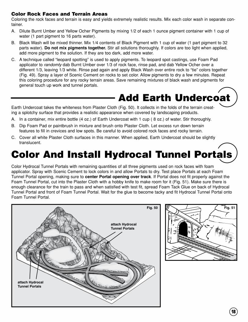
Color Hydrocal Tunnel Portals with remaining quantities of all three pigments used on rock faces with foam applicator. Spray with Scenic Cement to lock colors in and allow Portals to dry. Test place Portals at each Foam Tunnel Portal opening, making sure to center Portal opening over track. If Portal does not fit properly against the Foam Tunnel Portal, cut into the Plaster Cloth with a hobby knife to make room for it (Fig. 51). Make sure there is enough clearance for the train to pass and when satisfied with test fit, spread Foam Tack Glue on back of Hydrocal Tunnel Portal and front of Foam Tunnel Portal. Wait for the glue to become tacky and fit Hydrocal Tunnel Portal onto Foam Tunnel Portal.
Earth Undercoat takes the whiteness from Plaster Cloth (Fig. 50). It collects in the folds of the terrain creat-ing a splotchy surface that provides a realistic appearance when covered by landscaping products.
A. In a container, mix entire bottle (4 oz.) of Earth Undercoat with 1 cup ( 8 oz.) of water. Stir thoroughly.
B. Dip Foam Pad or paintbrush in mixture and brush onto Plaster Cloth. Let excess run down terrain features to fill in crevices and low spots. Be careful to avoid colored rock faces and rocky terrain.
C. Cover all white Plaster Cloth surfaces in this manner. When applied, Earth Undercoat should be slightly translucent.
Color Rock Faces and Terrain AreasColoring the rock faces and terrain is easy and yields extremely realistic results. Mix each color wash in separate con-tainer.
A. Dilute Burnt Umber and Yellow Ocher Pigments by mixing 1/2 of each 1 ounce pigment container with 1 cup of water (1 part pigment to 16 parts water).
B. Black Wash will be mixed thinner. Mix 1/4 contents of Black Pigment with 1 cup of water (1 part pigment to 32 parts water). Do not mix pigments together. Stir all solutions thoroughly. If colors are too light when applied, add more pigment to the solution. If they are too dark, add more water.
C. A technique called “leopard spotting” is used to apply pigments. To leopard spot castings, use Foam Pad applicator to randomly dab Burnt Umber over 1/3 of rock face, rinse pad, and dab Yellow Ocher over a different 1/3, leaving 1/3 white. Rinse pad again and apply Black Wash over entire rock to “tie” colors together (Fig. 49). Spray a layer of Scenic Cement on rocks to set color. Allow pigments to dry a few minutes. Repeat this coloring procedure for any rocky terrain areas. Save remaining mixtures of black wash and pigments for general touch up work and tunnel portals.
Add Earth Undercoat
Color And Install Hydrocal Tunnel Portals
Fig. 51Fig. 50
attach Hydrocal Tunnel Portals
attach Hydrocal Tunnel Portals

19
Woodland Scenics Road System consists of Paving Tape, a plastic spreader, Smooth-It and Top Coat. It is the ideal system for adding realistic roads, streets, sidewalks, or pavement to the layout. Also included is a set of six Cast Hydrocal Inclines. Plan placement of roads, town areas and road crossings. For suggest-ed road placement, see Fig. 56. Begin by drawing an outline of roads and paved areas with Foam Pencil (Fig. 55). Do this over level areas where you want build-ings and wherever you want paved roads. Country roads should be 2 1/2" wide and city streets should be 4 1/8" wide. If buildings are to be placed, test fit them now. When satisfied with placement of roads and paved areas, begin laying Paving Tape.
Add Road System
Fig. 55
Fig. 54
add Road System
Pin strips of Plaster Cloth to all sides of layout, with bumpy side out. On the front, and wherever possible, use a con-tinuous strip, allowing an inch or so to overlap the sides. Spray the Plaster Cloth thoroughly with water, working the plaster with your fingertips to fill in holes (Fig. 52). Apply around Access Panel areas, overlap opening by 1/2" (Fig. 53). When Plaster Cloth is thoroughly dried, cut Plaster Cloth out of Access Panel opening with hobby knife.
Fig. 52 Fig. 53
Plaster Cloth Sides of Layout
Items Needed• Smooth-It
• Cast Hydrocal-Inclines
• Paving Tape
• Bowl
• Top Coat Concrete and Asphalt
• Plastic spreader
• Wooden stirring stick
• Hobby knife
• Pencil
• 220-grit sandpaper
• Paintbrush

20
A. Make sure surface is clean and dry. Remove Track-Bed, from both sides of the track, the width of the Hydrocal Incline where the road crosses the track (Fig. 57). Use a hobby knife to cut and remove this material.
B. Test place each cast Incline in its notch in the Track-Bed. Make sure the tops are level with the top of the rails. Spread a layer of Foam Tack Glue on the bottom of each Incline and the Plaster Cloth surface and position (Fig. 58). The one angled Cast Hydrocal Incline goes in the position marked “C” ( Fig. 56).
C. Cut and place short lengths of Paving Tape between the rails and between the outside of the rail and the side of the Incline (Fig. 59 ).
D. Mix a small batch of Smooth-It according to carton directions.
E. Starting with the six rail crossings, fill areas between the Paving Tape with Smooth-It (Fig. 60). Use provided spreader to level Smooth-It even with the tops of the rails and the tops of Hydrocal Inclines (Fig. 60). With your fingernail, remove excess Smooth-It from top of the rails.
F. Let Smooth-It dry completely before removing Paving Tape from crossing area.
G. Carefully run a knife down the inside of the rails several times, scoring a groove in the Smooth-It to allow clearance for train wheels (Fig. 61).
H. Test clearance by running rolling stock over the area (Fig. 62). If necessary, sand down Smooth-It in between rails.
I. Repeat Steps K and L until train has proper clearance.
Fig. 60
Install Cast Hydrocal Inclines at Rail Crossings Fig. 57remove
Fig. 58
Cast Hydrocal Incline
PAVED ROAD
TOW
N STR
EET
DIRT ROAD
GRAVEL
GRAVEL
GRAVELGV 14
GV 1
0G
V13
GV
8GV7
GV12
GV9
GV
2
GV
5
GV1
GV
4
GV 15 GV 11
GV 6
GV 3
Fig. 56
A
B
I
I
I
I
I
C
tape
Fig. 59
Fig. 62Fig. 61

21
Two places, marked “A” and “B” in Fig. 56, require a piece of 1/4" foam sheet be placed between the rails as a level foundation for the road.
A. Notch the Track-Bed just like you did for the Hydrocal Inclines. The notch should be large enough to accept a 3 1/2" wide piece of foam and centered on the road path (Fig. 64).
B. To size the foam to fit tightly between the two sets of track, gently press the foam piece down on the rails to make impressions in the foam (Fig. 63).
C. With a hobby knife cut approximately 3/16" inside the impressions and trim to a close fit.
D. Test fit, trim if necessary and glue in place with Foam Tack Glue (Fig. 64). Do the same at “B”.
E. From the low ends of the Hydrocal Inclines, lay Paving Tape along outside of previously drawn outline of roads to form all road edges.
F. Do a section of road at a time and mix an appropriately sized batch of Smooth-It according to carton directions.
G. Starting at the low end of the Hydrocal Inclines, fill the road areas with Smooth-It and level evenly with top of Paving Tape (Fig. 66).
H. Following the street plan (Fig. 56), lay strips of Paving Tape on the outside of the lines defining the streets.
I. Make sure street edges line up with roads leading into the area.
J. Mix a batch of Smooth-It. Use Spreader to smooth level with top of Paving Tape.
K. Let all roads dry completely (30 to 40 minutes), fill holes and sand with 220-grit sandpaper until smooth.
L. Remove Paving Tape.
A. Place a new strip of Paving Tape on top of the street edges where you want curbs, sidewalks and building foundations (Fig. 67). This elevates the area above the street.
B. Where curbs, sidewalks and building foundations are planned, stack two new strips of Paving Tape parallel with the outside edge of the street. Keep Paving Tape strips within 4" of the street edge.
C. Mix another batch of Smooth-It. Use Spreader to smooth level with top of Paving Tape.
D. Allow to dry 30 minutes then remove Paving Tape.
Fig. 66
Make Roads and Streets
Add Curbs, Sidewalks and Foundations
Fig. 67
curb, sidewalk, building foundationdouble-stacked
Paving TapeNewPaving Tape
street(existing dried
Smooth-It)
base beneath town area
building front
Fig. 65
tape
low endof Hydrocal
Incline
Fig. 64
A
Fig. 63
Pressfoam gently
3 1/
2"

22
A. Following the path of the dirt road (Fig. 68), spray Scenic Cement over road surface.
B. Pour Buff Fine Ballast over the wet surface and add Soil and Earth Fine Turf to add realism to the dirt road.
C. When finished, spray entire road again with Scenic Cement to seal. Let dry.
E. If it is necessary to make the foundations wider,-stack two strips of Paving Tape parallel with the edge. Mix and pour another batch of Smooth-It between the Paving Tape and the existing foundation.
F. When Smooth-It is dry, remove tape and lightly sand with 220-grit sandpaper.
G. Paint raised foundation surface, roads and streets with Asphalt or Concrete Top Coat. We suggest using the Concrete Top Coat for foundation and sidewalk area and Asphalt for streets and roads.
Ballast is broken stones laid in a railroad bed to give stability to ties and rails. Use remaining Ballast from Tunnel Work steps on Page 9.
IMPORTANT: Before beginning this step, completely cover all turnouts and switch machines with masking tape to avoid damaging them.
A. Use a small paintbrush to apply Scenic Cement onto the sides of the Track-Bed, careful not to get any on rails.
B. Start at Tunnel #1. Pour Ballast over track and ties, avoiding turnouts and switch machines (Fig. 69). Make sure Track-Bed is completely covered.
C. Brush off excess Ballast from ties and rails and spread evenly with small dry paintbrush (Fig. 70).
D. Make sure Ballast is even with the ties for a realistic appearance.
E. Apply “wet water” (2 drops of liquid dish soap in one cup of water) on Ballast to prevent clumping.
F. Use an eyedropper to apply Scenic Cement on all Ballast, carefully avoiding rails.
G. If necessary, clean rails. Use sanding block with 600-grit sandpaper to keep rail surface clean.
Detail Dirt Roads
Ballast
Fig. 69 Fig. 70
Fig. 68dirt road

23
GV 15
Clump-Fol iageStreambedTreesBal last F ie ld GrassTalus
LandscapingFig. 71
Fig. 72
Items Needed• Various Turfs
• Talus
• Tree Armatures
• Clump-Foliage
• Field Grass
• Hob-e-Tac
• Foam Tack Glue
• Scissors
• Eyedropper or straw
• Liquid detergent
• Water
After the Plaster Cloth has been painted with Earth Undercoat, rock faces are attached and colored and the roads are built, it’s time to add landscaping. This process will add color, texture and realism to the layout.
All the provided products can be used in any fashion and quantity you wish. Use the box photo and Fig. 72 as a guide. The following instructions serve mainly to guide you through the process. Feel free to add the materials in the quantity and manner that best match your theme. Any mistake can be easily repaired.

24
Low Ground Cover
Medium Ground Cover
To create a realistic landscape, add low ground cover. This includes adding the smallest plants and grasses. It also includes dirt and soil. Initially, use these products sparingly. Later, you may add more to cover up seams, exposed Plaster Cloth and other areas.
Sprinkle Blended TurfA. Cut off corner of Green Blend Fine Turf bag and fill supplied shaker cup to 4 oz. mark. Tape shaker lid on cup.
B. Spray a few square feet of terrain with a mist of Scenic Cement.
C. While Scenic Cement is wet, take cup of Green Blend and lightly sprinkle thin layer over area sprayed with Scenic Cement, allowing portions of Earth Undercoat to be visible.
D. When layout is lightly covered, spray a second coat of Scenic Cement over the Green Blend. Fine TurfA. Cut off corner of Fine Turf colors - Yellow Grass, Burnt Grass, Soil and Earth. Use shaker cup to apply Turf colors, keeping in mind that Yellow Grass indicates areas which don’t get much water. Soil and Earth colors work well in gullies, drainage ditches, streambeds, trails, or similar eroded surfaces. Remember to blend coverings. B. When satisfied with appearance, mist all Turf with Scenic Cement, beginning 18" away and gradually bringing spray head closer to Turf. Spray Turf until thoroughly wet.
To add to the realistic landscape, add Medium Ground Cover. This provides the look of vines, taller grasses and weeds. This step also includes Talus: rock debris. At this point, landscaping items will begin to overlap to give a realis-tic touch to the layout.
Coarse TurfThe Medium Green Coarse Turf provides texture variation and can indicate weeds, coarse grass and small plants.
A. Spray a few square feet of terrain with a mist of Scenic Cement.
B. Cut a corner of the Medium Green Coarse Turf bag and sprinkle it over desired areas. Avoid rock faces.
C. Spray again with a mist of Scenic Cement to secure in place.
TalusTalus is rock debris, which collects beneath cliffs, around base of mountains, in erosion ruts and in front of rock faces.
A. Turn bag of Talus upside down to mix rock sizes. Cut corner off bag and use it as a shaker to sprinkle Talus. Be sure to add Talus below and around rock outcroppings and cliffs, in erosion areas, creek beds, around Tunnel Portals and drainage ditches.
B. Mix equal parts of Foam Tack Glue and water and a drop of liquid dish soap to make glue flow. With a straw or eyedropper, generously drop this mixture on Talus to attach it (Fig. 73). Allow to dry, then apply another coat and allow it to dry.
Fig. 73
High Ground CoverBuild and Install the TreesThis kit contains both deciduous and pine trees.
A. Remove temporary bases from the Tree Armatures. Twist and bend the deciduous Armatures to a realistic three- dimensional shape (Fig. 74A). Hold pine Armatures at the bottom and twist each pair of branches 90 degrees from the last lower pair, starting at the bottom.

25
Field GrassOn a scrap paper, place a small amount of Hob-e-Tac. Remove Field Grass from package. Separate a small clump from the batch and roll between fingers to produce uneven lengths. With scissors, cut one end of the clump evenly to serve as the bottom of the grass. Field Grass patches should be 1/4" to 3/8" to match scale. Dip bottom of Field Grass into Hob-e-Tac and place where desired on layout. Hold clump until it can stand on its own. Repeat process for addi-tional clumps.
To install trees, use a small drill bit or hobby knife to make a small hole in the Plaster Cloth where the tree will be placed. Place a drop of Hob-e-Tac over the hole. Place the bottom pin in the hole (Fig. 75).
Fig. 75
C.A. B.
Fig. 76
B. Using the brush applicator, paint Hob-e-Tac onto the branches of the Tree Armatures (Fig. 74B). Set in bases and wait 15 minutes until Hob-e-Tac is clear and tacky.
C. Dip the deciduous Armatures into any of the three Green Clump-Foliage bags for quick application, or apply Clump-Foliage by hand. For pine Armatures use the Conifer Green Clump-Foliage. Spray completed trees with Scenic Cement to secure loose foliage.
Fig. 74
Clump FoliageCreate bushes and shrubs with Clump-Foliage. Bushes tend to grow in “family groups” of one color, so it is best to place each of the three colors of Clump-Foliage in separate bush or shrub arrangements. Place dry to test appearance. When satisfied with placement, glue into place with Foam Tack Glue. Lightly spray the tops of Clump-Foliage “bushes” with Scenic Cement and sprinkle on Fine or Coarse Turf for highlighting.
Fig. 77
C.A. B.
C.A. B.

26
Finishing Touches
Painting the sides of the layout will give it a nice finished look. Use the Gray base paint supplied. Use a 2" paintbrush or roller (not provided) for this step.
A. Using a 220-grit sandpaper wrapped around a block, sand out the lumps and other rough areas on the sides of the layout.
B. Begin painting the front of the layout and work your way around.
Paint the Sides of the LayoutItems Needed• Disposable bowl or cup
• Gray base paint
• Paintbrush
• 220-grit sandpaper
The final step is detailing. Many of the finishing touches apply the principle of using the same products with vary-ing application techniques. Allow the layout to dry completely from previous steps before beginning the detailing.
Dry Brushing TurfTo add variation in Turf color, cover up bare spots, or cover other undesirable features, the Dry Brushing tech-nique allows you to see the results before attaching it.
A. Dip a dry paintbrush into any colors of Turf and brush it onto the layout where you want it. Add Soil or Earth Turf on top of Talus and along edges of Ballast to model dirt, which would have collected there. Apply Burnt Grass around bottoms of trees to model weeds and grasses.
B. When satisfied with Turf, spray lightly with Scenic Cement and allow to dry.
Adding Additional Landscape MaterialFor better variety in texture or color, added realism, or to cover gaps in terrain, use more Coarse Turf, Clump-Foliage, Fine or Blended Turf and Field Grass clumps, or any other landscape materials you wish. Burnt Grass and Yellow Grass Fine Turf can provide color variations in bushes, ground cover and trees. Spray Scenic Cement and lightly sprinkle Burnt Grass and Yellow Grass Fine or Coarse Turf on top.
Mount Buildings and Add DetailsNow that the layout is finished and you have added your special touches and details, it is time to add build-ings. If you have purchased the companion City & Industry Building Set, with its 165 detailed accessories and Dry Transfer Decals, mount your completed buildings on the layout. Remember, any HO scale buildings may be used, but City & Industry has been created especially for the Grand Valley HO scale layout.
Fig. 79
Fig. 78
C. Be careful to avoid edges where landscape begins.
D. Paint all sides and allow paint to dry.

27
Other PossibilitiesThough Grand Valley is a complete 4x8-foot layout, with modifications to the track plan and layout, it can be integrated into your present layout, or planned as one module of a larger modular system. Consult your
local HO scale module club for design specifications.
A Final WordThe Grand Valley HO Scale Lightweight Layout Kit (ST1483) is only one of the complete layouts offered by Woodland Scenics. For N scale, Woodland Scenics’ Scenic Ridge Lightweight Layout Kit (ST1482), includes all the Woodland Scenics' SubTerrain, Terrain and Landscaping components modelers needs to build a complete 3x6-foot layout. Just add the track, train and buildings.
To make adding buildings easy and inexpensive, Woodland Scenics offers both N and HO scale building sets. N scale modelers can purchase the Town and Factory Building Set (S1485). It contains 13 separate buildings and 70 detailed accessories that can be used on Scenic Ridge or any N scale layout. For HO scale modelers, Woodland Scenics offers the City & Industry Building Set (S1486). It has 15 individual build-ings and 160 detailed accessories that will bring Grand Valley -- or any HO layout -- to life! Our River Pass HO scale complete layout comes in three separate kits: Kit #1-River Pass Layout Kit (ST1484)- Includes the revolutionary SubTerrain System foam components- Risers, Inclines, Profile Boards, Foam Sheets, Plaster Cloth and Track-Bed-everything you need to create a 4x8-foot terrain base. Kit #2-River Pass Scenery Kit (S1488)- All the materials you need to cover the River Pass Layout Kit or any 4x8-foot layout. Includes
FlyspeckingDirt and soil collect in many areas including rock faces, on top of Ballast and on Turf areas. Woodland Scenics has a special technique called “flyspecking” that makes adding these details easy.
A. Spray the rock casting with water. Bend a sheet of paper into an “L” shape.
B. Place a small amount of Soil Fine Turf on the horizontal section of the paper.
C. Hold the paper near the rock castings and gently puff on the vertical sections of the paper. This will blow flyspecks of Soil onto the rock castings. If you apply too much Soil, brush it off with a dry paintbrush.
D. When satisfied, secure with Scenic Cement.
Shown with the City & Industry HO scale Building Set.

28
Tree Armatures, Bushes and Underbrush, Clump-Foliage, Fine-Leaf Foliage, Flowering Foliage, Field Grass, Dead Fall, our Road System, Ballast, Talus, one-pour water products and other landscaping materials.Kit #3-River Pass Building Kits (S1487)- Fifteen HO scale building kits, created with architectural authen-ticity and fine detail. Includes more than 210 detailed accessories, 110 Dry Transfer Decals and signs and posters.
Any track in the proper scale may be used on the Grand Valley or Scenic Ridge layouts, or River Pass, but Atlas Model Railroad Company Inc., has put together a convenient Scenic Ridge Track Pack #2588, Grand Valley Track Pack #589 and River Pass Track Pack #578.
For more information about the complete line of Woodland Scenics products, go to your favorite hobby shop, call 573-346-5555, or visit our Web site at: www.woodlandscenics.com.
Below is the list of Woodland Scenics’ products used to construct the Grand Valley Layout. If you would like to build a new layout or add landscaping to your Grand Valley Layout, just refer to the item name and number then go to your favorite hobby store and buy what you need. Woodland Scenics complete systems make it easy.
Item Number Description
SUBTERRAIN ITEMSST1407. . . . . . . . . . . . . . . . . . . . . . . . . . . . . . . . . . . . 1" Riser 4/pkg
ST1408 . . . . . . . . . . . . . . . . . . . . . . . . . . . . . . . . . . . 2" Riser 4/pkg
ST1411 . . . . . . . . . . . . . . . . . . . . . . . . . . . . . . . . . . . 4% Incline Set
ST1422. . . . . . . . . . . . . . . . . . . . . . . . . . . . . . . . .1/4" Foam Sheets
ST1419. . . . . . . . . . . . . . . . . . . . 8" Profile Boards and Connectors
ST1423. . . . . . . . . . . . . . . . . . . . . . . . . . . . . . . . .1/2" Foam Sheets
ST1431. . . . . . . . . . . . . . . . . . . . . . . . . . . . . . . . . . . . . Foam Pencil
ST1432. . . . . . . . . . . . . . . . . . . . . . . . . . . . . . . . . . . . 2" Foam Nails
ST1444. . . . . . . . . . . . . . . . . . . . . . . . . . . . 12 oz. Foam Tack Glue
ST1452. . . . . . . . . . . . . . . . . . . . . . . . . . . . . . . . . . . 1 Qt. Smooth-It
ST1453. . . . . . . . . . . . . . . . . . . . . . . . . . . . . . . . . Top Coat Asphalt
ST1454. . . . . . . . . . . . . . . . . . . . . . . . . . . . . . . . Top Coat Concrete
ST1455. . . . . . . . . . . . . . . . . . . . . . . . . . . . . 1/4" x 30’ Paving Tape
ST1474. . . . . . . . . . . . . . . . . . . . . . . . 24' HO Scale Track-Bed Roll
LANDSCAPING SYSTEM ITEMSB73 . . . . . . . . . . . . . . . . . . . . . . . . . . . . . . . . . . . . . Buff Fine Ballast
B80 . . . . . . . . . . . . . . . . . . . . . . . . . . . . . . . . . . Buff Medium Ballast
FC182. . . . . . . . . . . . . . . . . . . . . . . . . . Light Green Clump-Foliage
FC183. . . . . . . . . . . . . . . . . . . . . . . . Medium Green Clump-Foliage
FC184. . . . . . . . . . . . . . . . . . . . . . . . . . .Dark Green Clump-Foliage
FC185. . . . . . . . . . . . . . . . . . . . . . . . . . . . . . Conifer Clump-Foliage
FG172. . . . . . . . . . . . . . . . . . . . . . . . . . . .Harvest Gold Field Grass
T41 . . . . . . . . . . . . . . . . . . . . . . . . . . . . . . . . . . . . . . . Soil Fine-Turf
Item Number Description
T42 . . . . . . . . . . . . . . . . . . . . . . . . . . . . . . . . . . . . . . Earth Fine-Turf
T43 . . . . . . . . . . . . . . . . . . . . . . . . . . . . . . . . Yellow Grass Fine-Turf
T44 . . . . . . . . . . . . . . . . . . . . . . . . . . . . . . . . .Burnt Grass Fine-Turf
T49 . . . . . . . . . . . . . . . . . . . . . . . . . . . . . Green Blend Blended Turf
T64 . . . . . . . . . . . . . . . . . . . . . . . . . . . . Medium Green Coarse Turf
TR1101 . . . . . . . . . . . . . . . . . . . . . . 3/4"-3" Tree Armatures-36/pkg.
TR1102 . . . . . . . . . . . . . . . . . . . . . . . . 3"-5" Tree Armatures-14/pkg.
TR1103 . . . . . . . . . . . . . . . . . . . . . . . . . 5"-7" Tree Armatures-7/pkg.
TR1104 . . . . . . . . . . . . . . . . . . . . . 2 1/2"-4" Tree Armatures-42/pkg.
TR1105 . . . . . . . . . . . . . . . . . . . . . . . . 4"-6" Tree Armatures-24/pkg.
S193 . . . . . . . . . . . . . . . . . . . . . . . . . . . . Scenic Sifter Cup with Lid
S195 . . . . . . . . . . . . . . . . . . . . . . . . . . . . . . . . . Hob-e-Tac Adhesive
TERRAIN SYSTEM ITEMSC1201. . . . . . . . . . . . . . . . . . . . . . . . . . . . . . . Lightweight Hydrocal
C1203. . . . . . . . . . . . . . . . . . . . . . . . . . . . . . . . . . . . . .Plaster Cloth
C1220. . . . . . . . . . . . . . . . . . . . .Black Earth Colors Liquid Pigment
C1222. . . . . . . . . . . . . . .Burnt Umber Earth Colors Liquid Pigment
C1223. . . . . . . . . . . . . . Yellow Ocher Earth Colors Liquid Pigment
C1229. . . . . . . . . . . . Earth Undercoat Earth Colors Liquid Pigment
C1234. . . . . . . . . . . . . . . . . . . . . . . . . . . . . . . . Random Rock Mold
C1244. . . . . . . . . . . . . . . . . . . . . . . . . . . . . . . . . . .Facet Rock Mold
C1253. . . . . . . . . . . . . . . . . . . . . . . . . . . . . Cut Stone Single Portal
C1270. . . . . . . . . . . . . . . . . . . . . . . . . . . . . . . . . . . . Buff Fine Talus
C1271. . . . . . . . . . . . . . . . . . . . . . . . . . . . . . . . . Buff Medium Talus
Products

Woodland Scenics • PO Box 98 • Linn Creek, MO 65052 • www.woodlandscenics.com • U12 ©2000 OCO
FIR
ST
TIE
R A
LL
2" R
ISE
RS
EX
CE
PT
PIE
CE
S IN
DIC
AT
ED
BY
SE
CO
ND
TIE
R IN
CL
INE
S IN
DIC
AT
ED
BY
3” H
IGH
EN
D H
ER
E
STA
RT
3"
EN
D O
F4"
INC
LIN
E S
ET
HE
RE
2"-1
" IN
CL
INE
CU
T 2
"-1"
INC
LIN
E H
ER
EL
EA
VIN
G 9
"G
AP
INS
TAL
L R
EM
AIN
DE
R O
F2”
-1”
PIE
CE
HE
RE
BR
IDG
E
FR
ON
T E
DG
EO
F P
OR
TAL
FR
ON
T E
DG
EO
F P
OR
TAL
FR
ON
T E
DG
EO
F P
OR
TAL
STA
RT
HE
RE
WIT
H 2
" E
ND
OF
1" T
O 2
" IN
CL
INE
,C
LO
CK
WIS
E
STA
RT
HE
RE
WIT
H 2
" E
ND
OF
1" T
O 2
" IN
CL
INE
,WO
RK
CO
UN
TE
R-C
LO
CK
WIS
E
OVE
RPA
SS
RO
AD
TOWN S
TREET
GR
AVEL
GR
AVEL
GR
AV
EL
GR
AV
EL
GV
14
GV 10
GV 13
GV 8G
V 7
GV
12
GV
9
GV 2
GV 5
GV
1
GV 4
GV
6
GV
3
GV
15
GV
11
A =
9"
ST
RA
IGH
T...
......
......
......
......
......
......
11B
= 6
" S
TR
AIG
HT
......
......
......
......
......
......
....5
C =
3"
ST
RA
IGH
T...
......
......
......
......
......
......
.3D
= 2
" S
TR
AIG
HT
......
......
......
......
......
......
....6
E =
1 1
/2"
ST
RA
IGH
T...
......
......
......
......
......
.1
K =
LE
FT
TU
RN
OU
T S
WIT
CH
542
......
......
..1L
= R
IGH
T T
UR
NO
UT
SW
ITC
H 5
43...
......
...1
M =
90 ˚
CR
OS
SIN
G...
......
......
......
......
......
.....1
N =
60 ˚
CR
OS
SIN
G...
......
......
......
......
......
.....1
O =
9''
WA
RR
EN
TR
US
S B
RID
GE
......
......
...1
F =
1 1
/4"
ST
RA
IGH
T...
......
......
......
......
......
.1G
= 1
" S
TR
AIG
HT
......
......
......
......
......
......
....1
H =
18"
RA
DIU
S...
......
......
......
......
......
......
..34
I=
1/2
18"
RA
DIU
S...
......
......
......
......
......
....2
J=
1/3
18"
RA
DIU
S...
......
......
......
......
......
....3
GV
14