
HO Double Crossover Wiring Tutorial G. T. Galyon Olde ... · experienced builder somewhere between...
15
Page 1 HO Double Crossover Wiring Tutorial G. T. Galyon Olde Newburgh Model RR Club January 28th-2014 Introduction I would advise anyone to avoid complicated track configurations such as double crossovers, double slip switches, and three-way switches. A single crossover is much simpler to install reliably. However, it is often necessary to use complicated (and troublesome) track configurations to save space. In this article I have compiled information from my experiences with Shinohara HO gauge double crossovers some of which I believe are novel and not to be found elsewhere . I have assumed that the reader is familiar with the terms point rails, closure rails, frogs, flange ways, guard rails, etc. Double Crossover Overview for HO Scale Completed HO double crossovers can be purchased complete from Shinohara and Walthers. Shinohara manufactures, under their own name, HO double crossovers in code 70 and code 100 rail and they also manufacture the Walthers double crossover in code 83. Prices for Shinohara and Walthers double crossovers range between $60-80 dollars. Double Crossover kits can be purchased from Fast Tracks (www.handlaidtrack.com ) in a variety of rail sizes and there are people who will make-to-order double crossovers from Fast Tracks kits. I cannot give estimated prices range for these made-to order double crossovers but it should take an experienced builder somewhere between 3-5 hours to fabricate and test one double crossover. If you attempt to build your own Fast Tracks double crossover, and you are inexperienced, I should estimate a build time of 10-15 hours per crossover and the tooling/materials will be in excess of $200. Wiring strategies for Fast Tracks double crossovers can be found on the above referenced website. A third option is to cobble together a double crossover from four individual turnouts and one suitable crossing. Some “fitting” will be required to get these “cobbled together” double crossovers on 2” centers which is the standard spacing for parallel track in HO scale. The cost of a “cobbled together” double crossover is comparable to the Shinohara and Walthers doubles. Melvin Perry i has a web tutorial showing how to construct an HO double crossover on 2” centers using Atlas insul-frog switches and crossings. Shinohara double crossovers are reliable and smooth running if installed properly. It is critical that all trackage is “flat” (no humps or bumps) and “in gauge”. Electrical shorting can be a problem as engines traverse some Shinohara crossovers, but in DC mode engines tend to “roll through” shorts as long as the engine is moving fast enough and DC power packs usually have current limiting circuitry to prevent shorts from causing damage to the power pack. A Westside Q2 (4-4-6-4) will run through #6 Shinohara code 100 double crossover without derailing or stalling 80' Passenger cars will go through the Shinohara #6 double crossovers as will all the 6 axle diesels I have tested to date. I do not have a Shinohara #4 double crossover but I know that a Westside Q2 will not make it through a #4 single crossover without derailing.
Transcript of HO Double Crossover Wiring Tutorial G. T. Galyon Olde ... · experienced builder somewhere between...

Page 1
HO Double Crossover Wiring Tutorial G. T. Galyon
Olde Newburgh Model RR ClubJanuary 28th-2014
Introduction
I would advise anyone to avoid complicated track configurations such as double crossovers, double slip switches, and three-way switches. A single crossover is much simpler to install reliably. However, it is often necessary to use complicated (and troublesome) track configurations to save space. In this article I have compiled information from my experiences with Shinohara HO gauge double crossovers some of which I believe are novel and not to be found elsewhere . I have assumed that the reader is familiar with the terms point rails, closure rails, frogs, flange ways, guard rails, etc.
Double Crossover Overview for HO Scale
Completed HO double crossovers can be purchased complete from Shinohara and Walthers. Shinohara manufactures, under their own name, HO double crossovers in code 70 and code 100rail and they also manufacture the Walthers double crossover in code 83. Prices for Shinohara and Walthers double crossovers range between $60-80 dollars. Double Crossover kits can be purchased from Fast Tracks (www.handlaidtrack.com) in a variety of rail sizes and there are people who will make-to-order double crossovers from Fast Tracks kits. I cannot give estimated prices range for these made-to order double crossovers but it should take an experienced builder somewhere between 3-5 hours to fabricate and test one double crossover. If you attempt to build your own Fast Tracks double crossover, and you are inexperienced, I should estimate a build time of 10-15 hours per crossover and the tooling/materials will be in excess of $200. Wiring strategies for Fast Tracks double crossovers can be found on the above referenced website. A third option is to cobble together a double crossover from four individualturnouts and one suitable crossing. Some “fitting” will be required to get these “cobbled together” double crossovers on 2” centers which is the standard spacing for parallel track in HOscale. The cost of a “cobbled together” double crossover is comparable to the Shinohara and Walthers doubles. Melvin Perryi has a web tutorial showing how to construct an HO double crossover on 2” centers using Atlas insul-frog switches and crossings.
Shinohara double crossovers are reliable and smooth running if installed properly. It is critical that all trackage is “flat” (no humps or bumps) and “in gauge”. Electrical shorting can be a problem as engines traverse some Shinohara crossovers, but in DC mode engines tend to “roll through” shorts as long as the engine is moving fast enough and DC power packs usually have current limiting circuitry to prevent shorts from causing damage to the power pack. A WestsideQ2 (4-4-6-4) will run through #6 Shinohara code 100 double crossover without derailing or stalling 80' Passenger cars will go through the Shinohara #6 double crossovers as will all the 6 axle diesels I have tested to date. I do not have a Shinohara #4 double crossover but I know thata Westside Q2 will not make it through a #4 single crossover without derailing.

Page 2
As of February 2014 Shinohara has manufactured code 70, code 100, and (under the Walther's name) code 83 double crossovers. The C70 and “older version” Shinohara C100 double crossovers have two metal crossbars (see Figure1A-above ) across the point rails and are advertised as “non-DCC friendly”. Due to the metal crossbars both point rails are always at the same “polarity” and the open point rail will be opposite in polarity to its adjacent stock rail. For old version Shinoharas clearances between the open point rail and the adjacent stock rail are tight at about 0.060”) and wheels can potentially bridge the gap causing point-to-stock rail shorts. However, my own testing showed that point-to-stock rail shorting is a non-problem for old version Shinohara double crossovers even with long wheel-base steam engines, six axle diesels, and a miscellany of engines types with large flanges such as the older Rivarossi's.
Shinohara's new version C100 double crossovers are also advertised as non-DCC friendly but Mr. Shinohara implemented significant design changes that made these new version crossovers a lot more DCC friendlier than the older versions. Figure 2A (below) shows the point and closure rails for a new version Shinohara C100 double crossover. The point-to-stock rail clearances have been increased (about 0.095” versus 0.060”) and the point rail transition curvature is much more gradual than was the case for the older version Shinoharas. The remaining single crossbar is the reason why new version C100 double crossovers are advertisedas non-DCC friendly. However, I have yet to encounter any point-to-stock rail shorting with the new version C100 Shinohara double crossovers and even the infamous Rivarossi pizza cutter flanges make it through without point-to-stock rail shorting as do the sintered wheels found on older Athearn diesels.
Figure 1: Shinohara Old Version Double Crossover Point and Closure Rails

Page 3
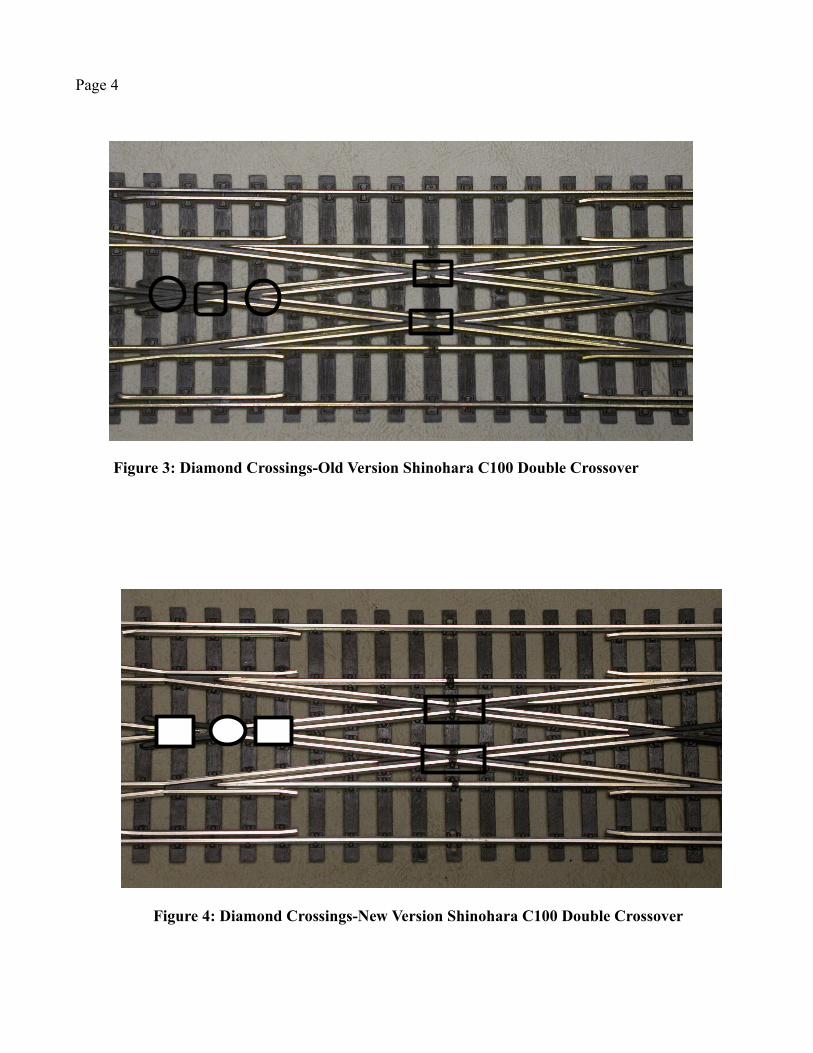
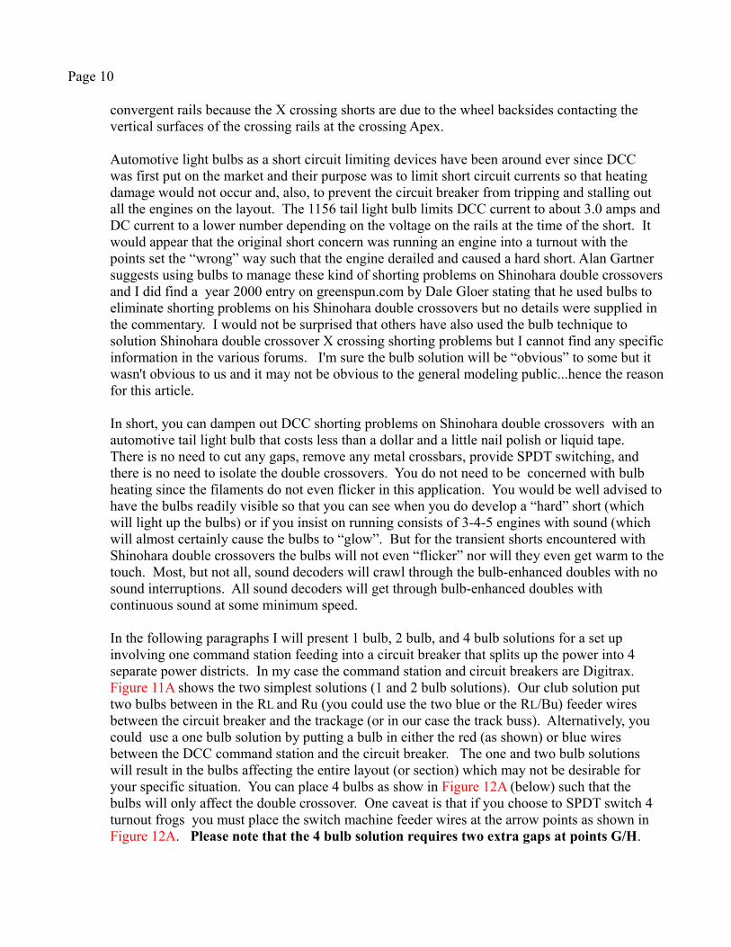
Figures 3A and 4A (below) show diamond crossings for old and new version Shinohara C100 double crossovers. The upper/lower crossings (the transparent rectangles) are called K crossings (Ku and KL) and the left/right hand crossings (the transparent circles) are called X crossings (XL and XR). The convergent X crossing rails are continuous across the crossing with one rail running underneath the other. The convergent K crossings rails/guard rails are not continuous across the gap. At a first glance it may appear that the old and new version crossings are identical but they are not and the differences are subtle but important. Consider the transparent circle and squares over the left hand X crossing in Figure 4A . The squares are over the Vee shaped plastic insulation separating two convergent rails and the circle is over the central part of the X crossings. From my observations it is the central part (the square) of the Xcrossings where all X crossing shorts occur. The new version Shinohara double crossover has substantially improved the insulation in the central part of the X crossings and I believe Mr. Shinohara did so to reduce/eliminate shorting. My own testing shows that I almost always get X crossing shorts on old version crossovers whereas I have yet to get any X crossing shorts on new version crossover X crossings. I, therefore, conclude that for my new version Shinohara C100 crossovers I do not have to be overly concerned about X crossing shorts . Obviously, the next question is; what about the K-crossings?
My testing shows that K crossings for both old and new version code 100 Shinohara double crossovers short out consistently when only (of two) divergent routes is set. Not everyone may have these results but when both divergent routes are set simultaneously I get no K crossing shorts. Before going any further I think it important to digress and take a more detailed look at the K crossings to understand what is going on? I think you will agree after we go through this exercise.
Figure 2: Shinohara New Version Code 100 Double Crossover-Point & Stock Rails
Page 4
Figure 4: Diamond Crossings-New Version Shinohara C100 Double Crossover
Figure 3: Diamond Crossings-Old Version Shinohara C100 Double Crossover

Page 5
Figures 5A and 6A (below) are polarity schematics for K crossings with red and blue representing different voltage polarities. Strictly speaking, polarity is not appropriate when discussing DCC but it is common usage. DCC is a form of AC and the difference between red and blue is a phase difference and not a voltage difference. If you set only one divergent route (with the other switches in the “through” position) the K crossing converging rails will have polarities as shown in Figure 5A (I.e. three red and one blue or three blue and one red), and if you simultaneously set both divergent routes the convergent rails will be at the same polarity (either red or blue) as shown in Figure 6A. In both Figures 5A and 6A I show a locomotive wheel (yellow) coming into the K crossing from the lower left and the rail color for that lower left segment is red. So let's “follow” the wheel as it traverses the K crossing from left to right as depicted in Figure 5A. If the wheel makes contact with (d) there will be a red-blue short A red-blue short is what we usually think about whenever we detect a short. Figure 6A is a K crossing schematic for the case where both divergent routes are set simultaneously and all four convergent rail/guard rails are at the same polarity. You cannot get red-blue shorting with this route configuration
Figure 5: K crossingPolarity Schematic - one divergent route set
Figure 6: K Crossing Polarity Schematic -two divergent routes set
a b
c d
a b
c d

Page 6
Walther's Code 83 Double Crossover
The C83 Walthers crossover is advertised as DCC friendly and it most certainly is due to some clever internal wiring (see Figure 7A below). You can install the C83 Walthers double with justpoint-to-stock rail switching and it will run smoothly w/o any shorting problems. It would be advisable to provide some positive retention to the throwbar so as to maintain an adequate contact pressure between the point and stock rails just to maintain continuity. The C83 turnout frogs are gapped fore and aft (i.e. they are “dead”) and my testing with very short wheel base engines has yet to find a dead frog problem, but if you do find “dead frog” problems it is easy enough to provide power to the isolated frogs . Walthers has removed all the metal crossbar/s and hard wired the point rails to their adjacent stock rails so that there cannot be any point-to-stock rail shorting. I can recommend the code 83 Walthers (Shinohara) double crossover but there are couple of caveats.
Firstly, the C83 has internal rail jumpers built into the crossover and sometimes these jumpers lose their electrical contact to the rails. My club (the Olde Newburgh Model RR Club in Walden, NY) has purchased two code 83 crossovers which worked right out of the box. We were also given a code 83 crossover (without a box) where all the jumpers on one side of the crossing had lost electrical contact. We have two members who have purchased code 83 crossovers and they tested out ok right out of the box. So, 4 of the 5 code 83s that we have in our possession were fine and the 5th was very probably mishandled before it got to us. I doubt that these jumper problems occurred in the factory. I think it is much more probable that they were mishandled during transportation or previous use. My advice is that you immediately test your C83 double crossover and return it immediately if you find any broken jumper wires. Youcan repair broken jumpers on the C83 but I would not recommend it unless you are an experienced solderer. Additional reading can be found on the web1.
1 http://www.modeltrainstuff.com/Walthers-HO-8812-Code-83-6-Double-Crossover-p/948-8812.htm
Figure 7: Walthers Code 83 Double Crossover Wiring Schematic-jumpers shown

Page 7
Secondly, there is the matter of flange-way binding or pinching. The NMRA specification for flange-way widths in HO gauge is 0.040-0.050”. The Shinohara old and new version C100 (and the old version C70 and C83)) crossovers have flange-way widths between 0.044-.045” which is almost dead in the middle of the NMRA specifications. The C83 crossover flange-ways are about the same...perhaps 0.043-0.044”. However, my testing shows that RP-25 (eithercode 88 or code 110) wheel sets will make it through the code 83 double crossover but there is some “wobble” which is probably due to flange-way tightness through the frogs in combinationwith rail curvatures on the divergent route rails as they approach the frogs. The “wobble” is minimal with most wheel sets and if your locomotive roster gets through the C83 crossover acceptably then do nothing. I did have a problem with my 1960s era Athearn SW 1500 switcher as it would bind up when going through the C83 crossover at crawl speeds. The same locomotive would not bind up in the C100 crossovers. My Bowser K-4 Pacific (a 4-6-2 steam model) would also bind up in the C83 when traversing the crossover at crawl speeds as did my (very old) Rivarossi 2-8-4. My Mantua 4-4-2 would derail on one of the divergent routes due to a slight ledge (i.e. difference in rail heights) across one of the frog gaps. However, I have run several red-box Rivarossi articulateds (with RP-25 wheel sets) through the Walthers code 83 double crossover without derailing or pinching. If you wish to improve running performance for your Walthers code 83 double crossover you may wish to consider smoothing out (i.e. burnishing) and/or widening the flange-ways. Burnishing would be essentially polishing or smoothing out the sides of the rails and plastic insulation while widening is done by removing material from the rail/plastic insulation sides. I usually burnish with styrene strips0.040 and 0.045” thick. I run the styrene strips through the flange-ways several times until I geta real smooth “slide” with no “bumpiness”. I then use a Dremel tool abrasive disk which is about 0.043” thick and slide that through the flange-ways. I think the main effect of these actions is to polish (i.e. burnish) the plastic insulation flange-ways. My narrowest flat sided diamond file is 0.045” thick and I can work that into the Shinohara flanges. When I use my 0.045” thick diamond flat file I do not run the file through the plastic insulation flange-ways. I only widen the flanges near the turnout frogs to facilitate long wheelbase steam engines and 6-axle diesels. Fast Tracks flange-way widths are 0.046-0.48” and I have not heard of any derailment or binding problems with FT double crossovers.
In the following sections I will focus on schemes for making Shinohara old and new version code 100 double crossovers DCC friendly without removing any metal crossbars or cutting any gaps in the rails.
Shinohara Code 100 Double Crossovers Wiring Schematics
Figure 8A is a generic schematic for Shinohara C100 double crossovers as manufactured with potential electrical trouble spots in circles. The point rails are shown in “neutral” positions. Red and Blue rails denote “polarities” while green rails are neutral and are switchable to either red or blue. The gaps that Shinohara builds into the design are located at points (I, Ku, KL, J). Some internet wiring schematics eliminate the gaps at (I,J) but I caution against that because switch machine contacts can really not be made to switch exactly simultaneously (there is always a little difference in the contact make-break times) and without those (I,J) gaps you mayget a red-blue short during the switching cycle. If you set only one divergent routes on the as-manufactured Shinohara C100 double crossovers you get what is shown in Figure 8A (below).

Page 8
In Figure 9A Both K crossings (Ku, KL) have all 4 convergent rails at the same “polarities” while the X crossings (XL, XR) have convergent rails with opposing polarities. In Figure 10A (below) I show a schematic for the Shinohara code 100 crossover with two divergent routes set simultaneously and the convergent rails at each K crossing have the same polarities.
While K crossings can be protected by setting both divergent routes simultaneously it is clear that the X crossings will have convergent rails of opposite polarity no matter what. And it is also clear that there are opposing point-to-stock rail polarities no matter the route setting. My recommended solution for X crossing shorting problems will not involve any rail gapping or SPDT (single pole double throw) switching and my point-to-stock rail shorting solution is essentially “do nothing”...it probably will not be a problem.
Ku
KL
I
J
XL XR
Ru
Bu
RL
BL
Ru
Bu
RL
BL
Figure 9: Shinohara Code 100 Double Crossover -one divergent route set
Ku
KL
B
C
XL XR
Ru
Bu
RL
BL
I
J
Ru
Bu
RL
BL
Figure 8: Shinohara Code 100 Double Crossover Schematic-Point Rails Neutral
Ku
KL
I
J
XL XR
Ru
Bu
RL
BL
Ru
Bu
RL
BL

Page 9
The Shinohara Code 100 X Crossing Solution/s
For the new version Shinohara code 100 double crossovers (advertised as non-DCC friendly)I recommend doing nothing at all other than setting both divergent routes simultaneously to eliminate the K crossing shorts. Mr. Shinohara has added enough insulation to the X crossings so that no shorts will be experienced in either DC or DCC mode and the point-to-stock rail clearances are wide enough so that shorting will probably never occur. If point-to-stock rail shorting should occur I would recommend gluing a 5 or 10 mil styrene strip to the outside of the open point rail on the divergent routes. Yes..removing the metal crossbars and wiring the point/stock rails together and SPDT (single pole double throw) power to gapped X crossings is a superior solution but I have run a wide variety of equipment through the new version doubles and have yet to experience an X-crossing or a point-to-stock rail shorting problems. Furthermore, I have experienced no pinching or wobbling as engines traverse the new version code 100 double crossover and I can crawl most engines through the crossings without any hesitations. And any hesitations are due to dead spot stalls and not shorting stalls.
The old version Shinohara double crossovers with the twin metal crossbars are another matter entirely. At my club (the Old Newburgh Model RR Club) our two old version Shinohara doubles gave us persistent shorting problems which we tried to solution by coating the K and X crossings with nail polish. Unfortunately, our results were unsatisfactory albeit with an occasional temporary success. One evening at a club session one of our members (Stephen Walsh) suggested we put a couple of light bulbs in the wiring and see what happened.
What happened was that in conjunction with some “strategically placed” nail polish (or liquid tape) the use of an automotive 1156 light bulb eliminated the X crossing shorts completely. We needed both the strategically placed insulation material AND the 1156 bulb to get results. One without the other was unsuccessful. Furthermore, the bulbs do not even glow during operation so there is no safety concern with hot bulbs starting fires. By “strategically placed” insulation material I mean that you have to put the insulation material on the vertical surfaces at the center of the X crossings. It is not necessary to put any insulation material on the top surfaces of the
Figure 10: Shinohara Code 100 Double Crossover -two divergent routes set
Ku
KL
A B
C D
XL XR
JJ
I
Ru
Bu
RuBu
RL
BL
RL
BL
Page 10
convergent rails because the X crossing shorts are due to the wheel backsides contacting the vertical surfaces of the crossing rails at the crossing Apex.
Automotive light bulbs as a short circuit limiting devices have been around ever since DCC was first put on the market and their purpose was to limit short circuit currents so that heating damage would not occur and, also, to prevent the circuit breaker from tripping and stalling out all the engines on the layout. The 1156 tail light bulb limits DCC current to about 3.0 amps and DC current to a lower number depending on the voltage on the rails at the time of the short. It would appear that the original short concern was running an engine into a turnout with the points set the “wrong” way such that the engine derailed and caused a hard short. Alan Gartner suggests using bulbs to manage these kind of shorting problems on Shinohara double crossoversand I did find a year 2000 entry on greenspun.com by Dale Gloer stating that he used bulbs to eliminate shorting problems on his Shinohara double crossovers but no details were supplied in the commentary. I would not be surprised that others have also used the bulb technique to solution Shinohara double crossover X crossing shorting problems but I cannot find any specificinformation in the various forums. I'm sure the bulb solution will be “obvious” to some but it wasn't obvious to us and it may not be obvious to the general modeling public...hence the reasonfor this article.
In short, you can dampen out DCC shorting problems on Shinohara double crossovers with an automotive tail light bulb that costs less than a dollar and a little nail polish or liquid tape. There is no need to cut any gaps, remove any metal crossbars, provide SPDT switching, and there is no need to isolate the double crossovers. You do not need to be concerned with bulb heating since the filaments do not even flicker in this application. You would be well advised tohave the bulbs readily visible so that you can see when you do develop a “hard” short (which will light up the bulbs) or if you insist on running consists of 3-4-5 engines with sound (which will almost certainly cause the bulbs to “glow”. But for the transient shorts encountered with Shinohara double crossovers the bulbs will not even “flicker” nor will they even get warm to thetouch. Most, but not all, sound decoders will crawl through the bulb-enhanced doubles with no sound interruptions. All sound decoders will get through bulb-enhanced doubles with continuous sound at some minimum speed.
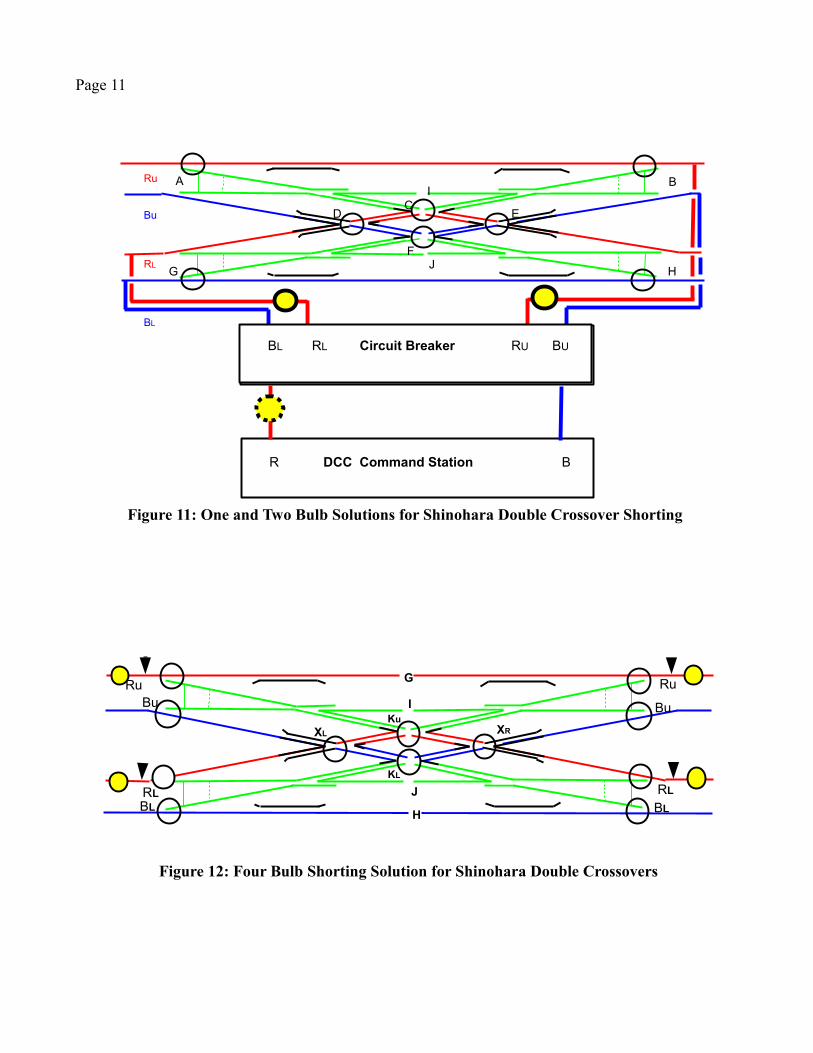
In the following paragraphs I will present 1 bulb, 2 bulb, and 4 bulb solutions for a set up involving one command station feeding into a circuit breaker that splits up the power into 4 separate power districts. In my case the command station and circuit breakers are Digitrax. Figure 11A shows the two simplest solutions (1 and 2 bulb solutions). Our club solution put two bulbs between in the RL and Ru (you could use the two blue or the RL/Bu) feeder wires between the circuit breaker and the trackage (or in our case the track buss). Alternatively, you could use a one bulb solution by putting a bulb in either the red (as shown) or blue wires between the DCC command station and the circuit breaker. The one and two bulb solutions will result in the bulbs affecting the entire layout (or section) which may not be desirable for your specific situation. You can place 4 bulbs as show in Figure 12A (below) such that the bulbs will only affect the double crossover. One caveat is that if you choose to SPDT switch 4 turnout frogs you must place the switch machine feeder wires at the arrow points as shown in Figure 12A. Please note that the 4 bulb solution requires two extra gaps at points G/H.
Page 11
Figure 11: One and Two Bulb Solutions for Shinohara Double Crossover Shorting
C
F
I
J
A B
G H
D E
Ru
Bu
RL
BL
BL RL Circuit Breaker RU BU
R DCC Command Station B
Figure 12: Four Bulb Shorting Solution for Shinohara Double Crossovers
KL
I
J
XL XR
RuBu
RLBL
Ru
Bu
RL
BL
G
H
Ku

Page 12
The gaps at G and H are not absolutely necessary but I like to have only one bulb in the short circuit path and without those gaps some of the short paths will have two bulbs in parallel which increases the maximum allowable surge current and there can be a hard short if the points are not set correctly. This solution does not isolate the double crossover but you cannot have any track feeder wires inside the bulbs on the red rails or the circles on the blue rails. You must force the short currents to go through one bulb to complete the circuit.
If you do utilize the four bulb solution I would caution you against doing any gapping or soldering at the four ends of the double crossover. Only four ties separate the point rail contact points from the end of the double crossover and you do not want to damage those ties. Put your gaps and solder contacts at least an inch outside of the double crossover. And if you are not experienced at soldering and gapping go two or more inches away.
The Circuit Breaker
For our DCC mode testing we used a Digitrax PM42 circuit breaker set at a trip current of 1.5 amperes and a delay time of approximately 500 milliseconds (the lowest current trip point and the slowest circuit breaker delay time). I have not tested all the possible combinations of current trip points and circuit breaker delay times and have no inclination to do so. Since the bulbs do not light up at all I feel all the current trip levels (which range from 1.5 to 12.0 amperes) would work in conjunction with the circuit breaker delay time of 500 milliseconds. The PM42 is a mechanical relay type of circuit breaker and is more sensitive to current surges than solid state circuit breakers so I feel that if we can make the bulb enhancement system work with a PM42 there should be no problems with other circuit breakers provided that the circuit breaker delay times can be adjusted to 500 milliseconds.
Solution Rationale
A metal-to-metal short at the X crossings would result in all current being diverted through the short with no current being delivered to the engine motor. In addition, there would be a zero voltage drop across the motor. If a bulb is placed in series with a metal-to-metal short all the voltage will be “on” the bulb causing the bulb to heat up (thereby increasing the bulb resistance)and clamp the current. For an 1156 bulb the DCC clamp current is about 3-3.1 amperes.
If you coat the bare vertical surfaces of the X crossings with an dielectric material (such as nail polish or liquid tape) then the metal-to-metal short is transformed to a metal-insulator-metalor capacitor. If the insulator material is “thick” the capacitance will be “very small” and the capacitor charging currents will be “very small”. Mr. Shinohara's new version double crossovers have “thick” dielectric material coating the horizontal surfaces of the X crossings and the resultant capacitor charging currents are “very small”...essentially zero. However, if thedielectric material is “thin” the capacitance will be “larger” and the capacitor charging currents will be “larger”. For the thin dielectric material coatings the charging currents under DCC voltages may be large enough to trip the circuit breakers even though a voltage is maintained across both the capacitive “short” and the engine motor. If a bulb is placed in the circuit the capacitor charging current will be reduced without much of an effect on the current flow through the motor. If the capacitor charging current reduction is large enough the circuit

Page 13
breaker trip current will not be exceeded. As long as the capacitor charging times are short enough the full input voltage will be applied across the load. Since I see no speed “bumps” as engines traverse the old version Shinohara double crossover with “bulb enhancement” I will presume that the peak voltage across the motor-capacitance short is approximately 16 volts .
I know that the electrical engineers amongst the readers of this document would prefer to see a circuit model that backs up the explanation given above. Figure 13A (below) is an RC circuit schematic that I believe represents the situation described above. This circuit is well known in electrical engineering textbooks and is called an RC low pass filter circuit. At the beginning of each charging cycle there is a relatively large current surge into the capacitor which quickly subsides as the capacitor voltage is increased from zero to full voltage. The current surge peak value is equal to:
I c = V in / R
What appears to be happening is that the current surge rapidly heats up the bulb thereby increasing the bulb resistance significantly and dampening the current surge peak value such that the main circuit breaker does not trip. As previously noted, I saw no evidence of filament flickering during the testing.
I am well aware that the Digitrax PM42 circuit breaker used in this testing has a reputation for being sensitive to capacitance inrush current spikes. It may well be that other circuit breakers may not react to inrush current spikes in a similar manner and that the bulb protection describedin this article may be unnecessary. It could also be the case that increasing the circuit breaker trip currents from the 1.5 amp value used in these measurements may also solve the tripping problem without resorting to bulb protection. Etc., Etc. While this article specifically dealt with Shinohara double crossovers I would not be surprised if similar results occurred with crossings. Our club had crossings which always shorted out when traversed by any engine and we solutioned the problem by removing the crossings. This was before we stumbled across this bulb enhanced double crossover solution. We at least still have the crossings.
Figure 13: Low Pass RC Filter Circuit
Rbulb
C R load
IcIL
I total
Page 14
J and B Weld
After the above document was written I tested the use of J and B weld as insulation material on the X-crossings and found that the J and B weld seems to wear longer than either the ink or liquid tape. It was a bit more difficult to get good coverage on the vertical surfaces and requiredsome filing of the vertical surfaces to open up the flange ways but the improved wear resistance is worth the extra care required during application.
Conclusion and Acknowledgments
I hope this document is useful to the modeling community. There are a lot of Shinohara double crossovers around and they are the only game in town if you want a factory made double crossover. So have at it and let us know what happens.
I do need to acknowledge the help of the Old Newburgh Model RR Club in Walden, NY which provided all the double crossovers used for testing and, in particular, to members Steve Walsh, George Moore, Peter Bach, Tom Smith, and Ed Miller. It was Steve who first proposed the bulbenhancement idea, George who provided the test trackage, Tom who provided the DCC function, and Ed and Peter who did a lot of the early engine testing. I am also grateful to Steve Daggott for his help and advice.
George T. Galyon Olde Newburgh Model RR ClubWalden, NY

i. http://www.greenspun.com/bboard/q-and-a-fetch-msg.tcl?msg_id=0041fu