HLD/SLD - prestolifts.com
26
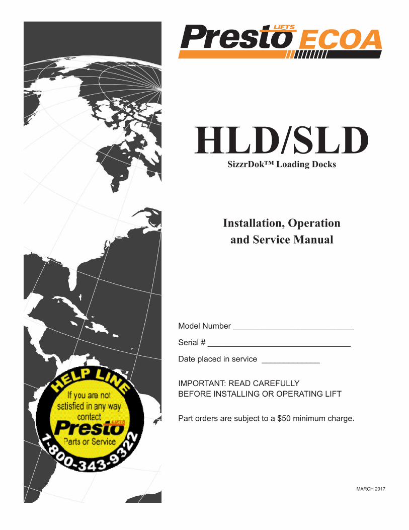
HLD/SLD SizzrDok™ Loading Docks Installation, Operation and Service Manual Model Number ___________________________ Serial # ________________________________ Date placed in service _____________ IMPORTANT: READ CAREFULLY BEFORE INSTALLING OR OPERATING LIFT Part orders are subject to a $50 minimum charge. MARCH 2017
Transcript of HLD/SLD - prestolifts.com
HLD/SLDSizzrDok™ Loading Docks
Installation, Operationand Service Manual
Model Number ___________________________
Serial # ________________________________
Date placed in service _____________
IMPORTANT: READ CAREFULLYBEFORE INSTALLING OR OPERATING LIFT
Part orders are subject to a $50 minimum charge.
MARCH 2017

2 HLD-SLD PRESTO-ECOA OWNER’S MANUAL
This manual was current at the time of printing. To obtain the latest, most updated version, please contact Presto-ECOA Lifts Customer Service Department or go to our website: www.PrestoLifts.com where you will find a complete list of current owner’s manuals to print.
HLD-SLD PRESTO-ECOA OWNER’S MANUAL 3
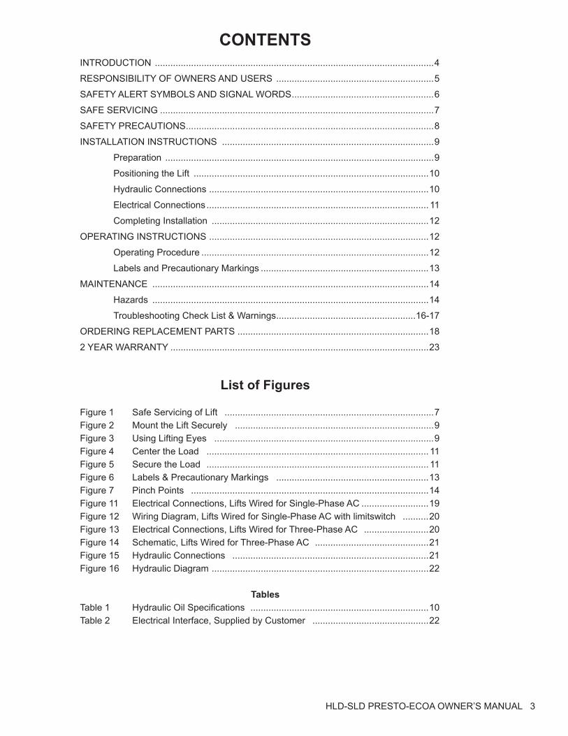
CONTENTSINTRODUCTION ............................................................................................................4
RESPONSIBILITY OF OWNERS AND USERS .............................................................5
SAFETY ALERT SYMBOLS AND SIGNAL WORDS .......................................................6
SAFE SERVICING ..........................................................................................................7
SAFETY PRECAUTIONS ................................................................................................8
INSTALLATION INSTRUCTIONS ..................................................................................9
Preparation ........................................................................................................9
Positioning the Lift ...........................................................................................10
Hydraulic Connections .....................................................................................10
Electrical Connections ...................................................................................... 11
Completing Installation ....................................................................................12
OPERATING INSTRUCTIONS .....................................................................................12
Operating Procedure ........................................................................................12
Labels and Precautionary Markings .................................................................13
MAINTENANCE ...........................................................................................................14
Hazards ...........................................................................................................14
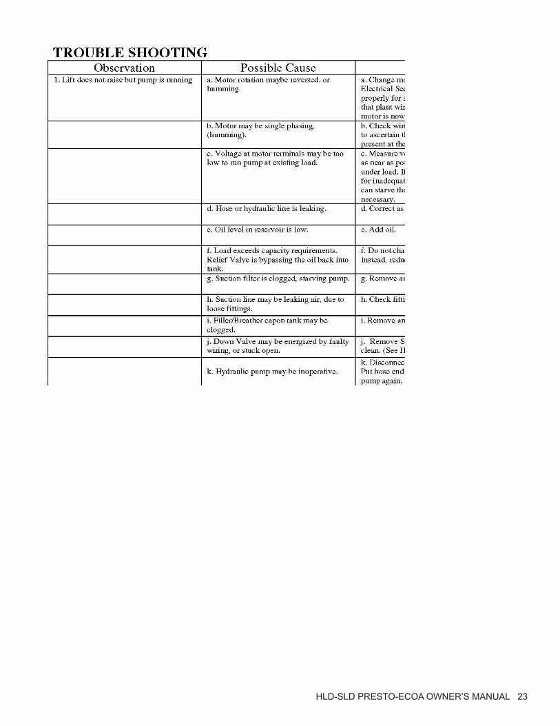
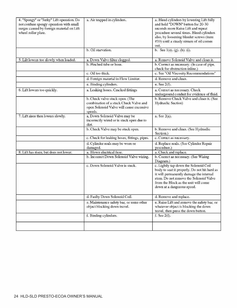
Troubleshooting Check List & Warnings ......................................................16-17
ORDERING REPLACEMENT PARTS ..........................................................................18
2 YEAR WARRANTY ....................................................................................................23
List of Figures
Figure 1 Safe Servicing of Lift .................................................................................7Figure 2 Mount the Lift Securely .............................................................................9Figure 3 Using Lifting Eyes .....................................................................................9Figure 4 Center the Load ...................................................................................... 11Figure 5 Secure the Load ...................................................................................... 11Figure 6 Labels & Precautionary Markings ...........................................................13Figure 7 Pinch Points ............................................................................................14 Figure 11 Electrical Connections, Lifts Wired for Single-Phase AC ..........................19Figure 12 Wiring Diagram, Lifts Wired for Single-Phase AC with limitswitch ..........20Figure 13 Electrical Connections, Lifts Wired for Three-Phase AC .........................20Figure 14 Schematic, Lifts Wired for Three-Phase AC ............................................21Figure 15 Hydraulic Connections ............................................................................21Figure 16 Hydraulic Diagram ....................................................................................22
TablesTable 1 Hydraulic Oil Specifications .....................................................................10Table 2 Electrical Interface, Supplied by Customer .............................................22
4 HLD-SLD PRESTO-ECOA OWNER’S MANUAL
S E C T I O N 1
Getting StartedPLEASE READ THE INSTALLATION INSTRUCTIONS CAREFULLY BEFORE INSTALLING, USING OR SERVICING THE DOCK LIFT.
The safety of all persons installing, using or servicing the Dock Lift is of utmost importance to Presto-Ecoa. The Dock Lift is capable of supporting heavy loads and is capable of causing SE-VERE PERSONAL INJURY if used improperly or certain safety precautions are not taken. When properly used and maintained, the Dock Lift will provide many years of safe, trouble free service. If you have any questions about any of the instructions in this manual or about the use of this product, PLEASE contact your DEALER or ECOA.
InspectionIMMEDIATELY upon receipt of the Dock Lift, remove all packing and strapping material and visually inspect the unit for damage. Any damage to the loading dock MUST BE NOTED on the delivery receipt. After the preliminary inspection is conducted, the loading dock should be thor-oughly inspected for any concealed damage that was not readily apparent during the preliminary inspection. Any concealed damage found that was not noted on the delivery receipt should be IMMEDIATELY reported in writing TO THE DELIVERING CARRIER.
HLD-SLD PRESTO-ECOA OWNER’S MANUAL 5
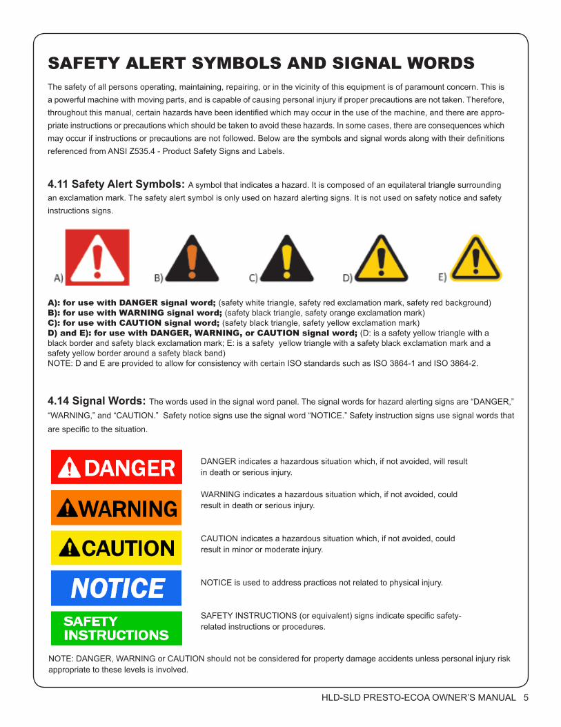
SAFETY ALERT SYMBOLS AND SIGNAL WORDSThe safety of all persons operating, maintaining, repairing, or in the vicinity of this equipment is of paramount concern. This is a powerful machine with moving parts, and is capable of causing personal injury if proper precautions are not taken. Therefore, throughout this manual, certain hazards have been identified which may occur in the use of the machine, and there are appro-priate instructions or precautions which should be taken to avoid these hazards. In some cases, there are consequences which may occur if instructions or precautions are not followed. Below are the symbols and signal words along with their definitions referenced from ANSI Z535.4 - Product Safety Signs and Labels.
4.11 Safety Alert Symbols: A symbol that indicates a hazard. It is composed of an equilateral triangle surrounding an exclamation mark. The safety alert symbol is only used on hazard alerting signs. It is not used on safety notice and safety instructions signs.
4.14 Signal Words: The words used in the signal word panel. The signal words for hazard alerting signs are “DANGER,”
“WARNING,” and “CAUTION.” Safety notice signs use the signal word “NOTICE.” Safety instruction signs use signal words that
are specific to the situation.
DANGER indicates a hazardous situation which, if not avoided, will result in death or serious injury.
WARNING indicates a hazardous situation which, if not avoided, could result in death or serious injury.
CAUTION indicates a hazardous situation which, if not avoided, could result in minor or moderate injury.
NOTICE is used to address practices not related to physical injury.
SAFETY INSTRUCTIONS (or equivalent) signs indicate specific safety-related instructions or procedures.
NOTE: DANGER, WARNING or CAUTION should not be considered for property damage accidents unless personal injury risk appropriate to these levels is involved.
A): for use with DANGER signal word; (safety white triangle, safety red exclamation mark, safety red background)B): for use with WARNING signal word; (safety black triangle, safety orange exclamation mark)C): for use with CAUTION signal word; (safety black triangle, safety yellow exclamation mark)D) and E): for use with DANGER, WARNING, or CAUTION signal word; (D: is a safety yellow triangle with a black border and safety black exclamation mark; E: is a safety yellow triangle with a safety black exclamation mark and a safety yellow border around a safety black band)NOTE: D and E are provided to allow for consistency with certain ISO standards such as ISO 3864-1 and ISO 3864-2.
6 HLD-SLD PRESTO-ECOA OWNER’S MANUAL
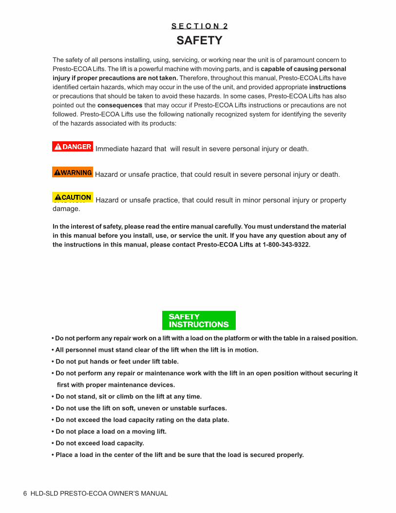
WARNING!
• Do not perform any repair work on a lift with a load on the platform or with the table in a raised position.
• All personnel must stand clear of the lift when the lift is in motion.
• Do not put hands or feet under lift table.
• Do not perform any repair or maintenance work with the lift in an open position without securing it
first with proper maintenance devices.
• Do not stand, sit or climb on the lift at any time.
• Do not use the lift on soft, uneven or unstable surfaces.
• Do not exceed the load capacity rating on the data plate.
• Do not place a load on a moving lift.
• Do not exceed load capacity.
• Place a load in the center of the lift and be sure that the load is secured properly.
S E C T I O N 2
SAFETYThe safety of all persons installing, using, servicing, or working near the unit is of paramount concern to Presto-ECOA Lifts. The lift is a powerful machine with moving parts, and is capable of causing personal injury if proper precautions are not taken. Therefore, throughout this manual, Presto-ECOA Lifts have identified certain hazards, which may occur in the use of the unit, and provided appropriate instructions or precautions that should be taken to avoid these hazards. In some cases, Presto-ECOA Lifts has also pointed out the consequences that may occur if Presto-ECOA Lifts instructions or precautions are not followed. Presto-ECOA Lifts use the following nationally recognized system for identifying the severity of the hazards associated with its products:
DANGER – Immediate hazard that will result in severe personal injury or death.
WARNING – Hazard or unsafe practice, that could result in severe personal injury or death.
CAUTION – Hazard or unsafe practice, that could result in minor personal injury or property damage.
In the interest of safety, please read the entire manual carefully. You must understand the material in this manual before you install, use, or service the unit. If you have any question about any of the instructions in this manual, please contact Presto-ECOA Lifts at 1-800-343-9322.
HLD-SLD PRESTO-ECOA OWNER’S MANUAL 7
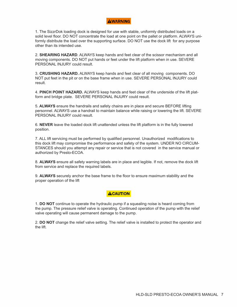
WARNING!
1. The SizzrDok loading dock is designed for use with stable, uniformly distributed loads on a solid level floor. DO NOT concentrate the load at one point on the pallet or platform. ALWAYS uni-formly distribute the load over the supporting surface. DO NOT use the dock lift for any purpose other than its intended use.
2. SHEARING HAZARD. ALWAYS keep hands and feet clear of the scissor mechanism and all moving components. DO NOT put hands or feet under the lift platform when in use. SEVERE PERSONAL INJURY could result.
3. CRUSHING HAZARD. ALWAYS keep hands and feet clear of all moving components. DO NOT put feet in the pit or on the base frame when in use. SEVERE PERSONAL INJURY could result.
4. PINCH POINT HAZARD. ALWAYS keep hands and feet clear of the underside of the lift plat-form and bridge plate. SEVERE PERSONAL INJURY could result.
5. ALWAYS ensure the handrails and safety chains are in place and secure BEFORE lifting personnel. ALWAYS use a handrail to maintain balance while raising or lowering the lift. SEVERE PERSONAL INJURY could result. 6. NEVER leave the loaded dock lift unattended unless the lift platform is in the fully lowered position.
7. ALL lift servicing must be performed by qualified personnel. Unauthorized modifications to this dock lift may compromise the performance and safety of the system. UNDER NO CIRCUM-STANCES should you attempt any repair or service that is not covered in the service manual or authorized by Presto-ECOA.
8. ALWAYS ensure all safety warning labels are in place and legible. If not, remove the dock lift from service and replace the required labels.
9. ALWAYS securely anchor the base frame to the floor to ensure maximum stability and the proper operation of the lift
CAUTION!
1. DO NOT continue to operate the hydraulic pump if a squealing noise is heard coming from the pump. The pressure relief valve is operating. Continued operation of the pump with the relief valve operating will cause permanent damage to the pump. 2. DO NOT change the relief valve setting. The relief valve is installed to protect the operator and the lift.
8 HLD-SLD PRESTO-ECOA OWNER’S MANUAL
RESPONSIBILITY OF OWNERS AND USERS Inspection and MaintenanceThe device shall be inspected and maintained in proper working order in accordance with Presto-ECOA owner’s manual.
Removal from ServiceAny device not in safe operating condition such as, but not limited to, excessive leakage, missing rollers, pins, or fasteners, any bent or cracked structural members, cut or frayed electric, hydrau-lic, or pneumatic lines, damaged or malfunctioning controls or safety devices, etc. shall be re-moved from service until it is repaired to the original manufacturer’s standards.
RepairsAll repairs shall be made by qualified personnel in conformance with Presto-ECOA instructions.
OperatorsOnly trained personnel and authorized personnel shall be permitted to operate these lifts.
Before OperationBefore using the device, the operator shall have:• Read and/or had explained, and understood, the manufacturer’s operating instructions and
safety rules.• Inspected the device for proper operation and condition. Any suspect item shall be carefully
examined and a determination made by a qualified person as to whether it constitutes a haz-ard. All items not in conformance with Presto-ECOA’s specification shall be corrected before further use of these lifts.
During OperationThe device shall only be used in accordance with this owner’s manual.• Do not overload.• Ensure that all safety devices are operational and in place.
Modifications or AlterationsModifications or alterations to any Presto-ECOA industrial positioning equipment shall be made only with written permission from Presto-ECOA.
HLD-SLD PRESTO-ECOA OWNER’S MANUAL 9
IINSTALLATION INSTRUCTIONS
1. Check pit for conformity to installation drawing provided.
2. Locate the power unit. Note: It is suggested that power unit be installed prior to the installation of the lift. This allows the electrical work to be completed ahead of time. Also, it permits flushing of thehydraulic lines with the power unit prior to connecting the lift.
Note: Hydraulic oil is not supplied with the equipment, unless the optional installation kithas been purchased.
3. All underground hydraulic lines must be flushed with clean oil.
4. Remove the skid and all steel strapping. The unit comes with four (4)-lifting tabs fitted on the platform. These are to be used for lifting the unit with a crane or a fork truck. At this point DO NOT remove the two (2) shipping bolts.
5. With the help of a crane or fork truck, lift the dock lift unit and position it in the pit. Note that the hydraulic cylinder end is opposite to the end of the oil line recess in the pit.
6. Remove the two (2) shipping bolts. Lift the dock lift with the help of a fork truck. Make sure that the base frame assembly remains on the ground and that the scissor legs open properly. Engage the maintenance devices as explained in “Scissor Blocking Instructions” section. Check to ensure that the maintenance safety bars are securely in place.
7. After flushing the hydraulic lines, proceed as follows:Connect the hydraulic hose coming from the conduit to the Flare bulkhead fitting on the base frame assembly.
Note: The hydraulic hose is not typically supplied by Presto-ECOA. Hose and tubng supplied by others must conform to manufacturer’s specifications.
8. The upper travel limit switch is factory installed to the bracket on the base frame at the scissor leg clevis hinge. Make sure the limit switch wire runs through the conduit to the control box.Press the “UP” button until the cylinders are filled with oil and the lift rises.
9. Disengage the maintenance safety bars as explained in “Scissor Blocking Instructions” section. Completely lower the platform by pressing the ‘’DOWN’’ button until the unit is in fully lowered position. (Note: Motor runs only when the Lift is rising. Only the Solenoid operates when the Lift is lowering.)
10. Position the lift so that there are proper clearances around the edges (Refer to Installation drawing on page 9).
11. Raise the lift completely and engage the maintenance bars. Mark the base frame lag down holes; shift the position of the lift to allow room for drilling, then drill. When complete, reposition the lift, shim until level. Install anchors, lagging the lift securely to the floor. (Make sure that base angles are fully supported along their entire length with shims or concrete grout.) Note: Anchoring holes may be drilled through existing holes using the base frame as a template.
10 HLD-SLD PRESTO-ECOA OWNER’S MANUAL
INSTALLATION INSTRUCTIONS(continued)
12. Disengage the maintenance safety bars and lower the lift to check for proper height. The plat-form should be flush with the curb angles around the pit.
13. Operate the lift through a few cycles holding the ‘’DOWN’’ button on for 10-20 seconds after the lift is fully lowered. This procedure will bleed any remaining air that may be in the hydraulic lines. 14. For lifts equipped with an upper travel limit switch, raise the lift again and set the limit switch (normally closed contact) so that the motor shuts off when the platform reaches the desired height from the ground.
15. Note to Installer: In order to ensure a clean, trouble free, hydraulic system and to prevent the suction filter from clogging due to foreign particles in the pipe, the installer must run the lift ‘’UP’’ and “DOWN’’ at least 15 times. Lower the lift and turn off the power supply. Remove the solenoid valve from the valve block and clean thoroughly, making sure that the dirt does not enter the valves. This procedure will ensure trouble free operation of the lift.
16. Check the oil level of the reservoir with the lift fully lowered. It should be approximately 1’’ below the top of the tank. Add oil if necessary.
17. Clean up spilled oil and debris from the area.Note to installer; Spilled oil left in the area may be misinterpreted as a leak and may cause a needless “call- back’’.
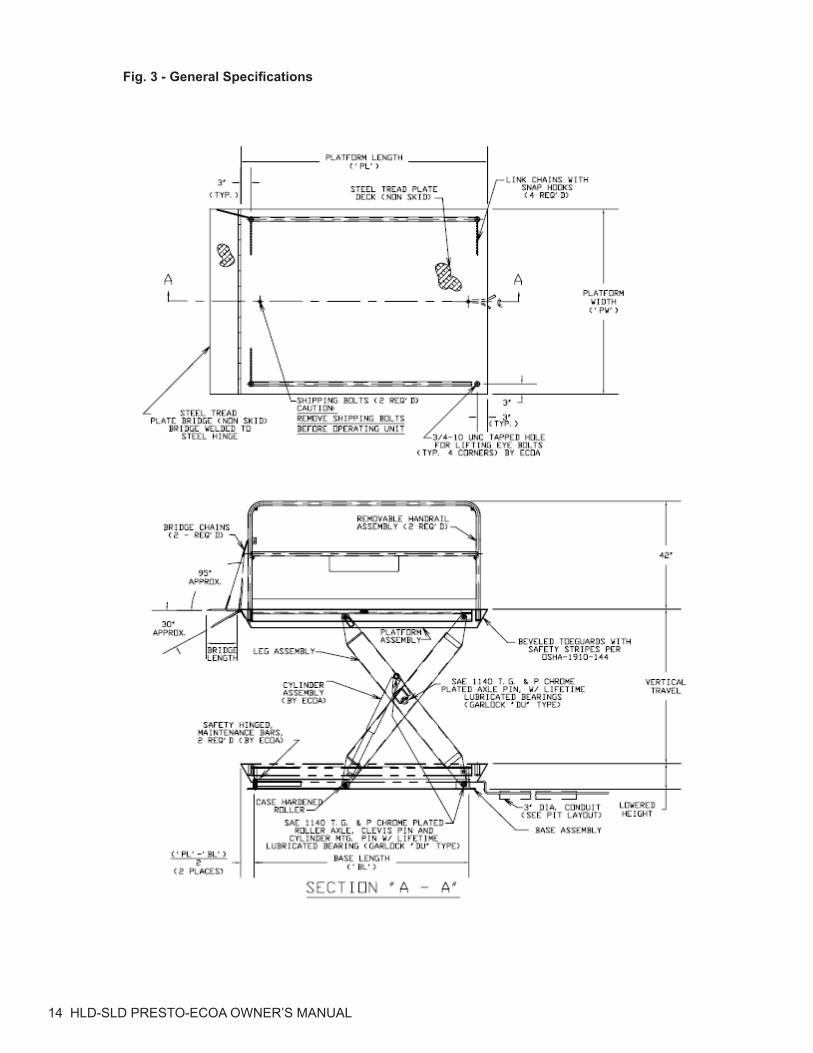
FUNCTIONAL DESCRIPTIONThe SizzrDok series of lifts have been primarily designed for loading dock applications. The most important advantage of the SizzrDok is that it is finitely adjustable in height. The installation of this lift provides full flexibility, allowing you to load and unload at any truck bed elevation within the lift’s travel range. The general specifications for the SizzrDok Series Dock Lifts are as shown in Figure 3.
SCISSOR BLOCKING INSTRUCTIONSTo Engage the Maintenance Bars; HLD:
1. REMOVE ALL LOADS from the platform and depress the “up” button to raise the dock lift to its fully raised position.
2. Rotate each maintenance bar until it hits the inside of the roller channel. Ensure both maintenance bars are properly positioned against the roller channel.
3. Lower the dock lift by pressing the “DOWN” button until the rollers stop against themaintenance bars and the lift ceases to come down any further.
HLD-SLD PRESTO-ECOA OWNER’S MANUAL 11
SCISSOR BLOCKING INSTRUCTIONS (continued)
To Engage the Maintenance Bars; SLD:
4. REMOVE ALL LOADS from the platform and depress the “up” button to raise the dock lift to its fully raised position.
5. Position each removable maintenance bar so that it hits the inside of the roller channel, and the inside of the base end angle. Ensure that the safety tabs on the maintenance bars are engaged over the side and base angles.
6. Lower the dock lift by pressing the “DOWN” button until the rollers stop against the mainte-nance bars and the lift ceases to come down any further.
To Disengage the Maintenance Bars; HLD, SLD:
1. Raise the dock lift by pressing the ‘up” button until the rollers are well clear of the mainte-nance bar.
2. Rotate (HLD), or remove (SLD), each maintenance bar back to its original position.
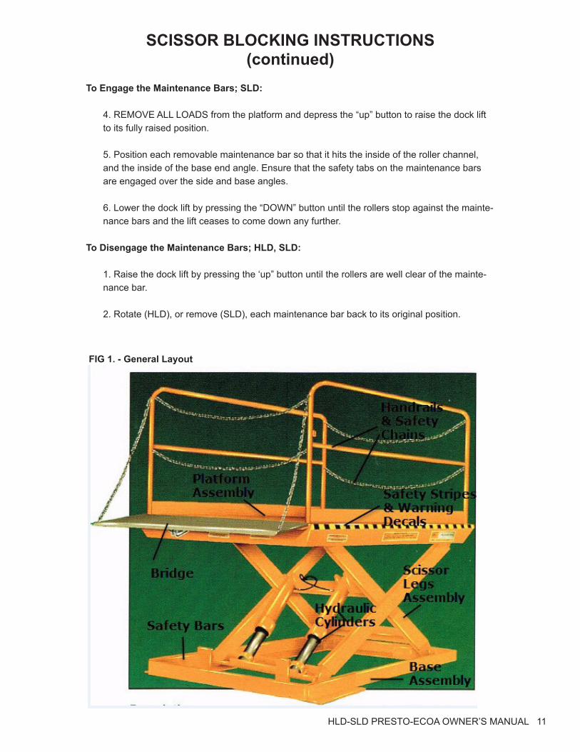
FIG 1. - General Layout

12 HLD-SLD PRESTO-ECOA OWNER’S MANUAL
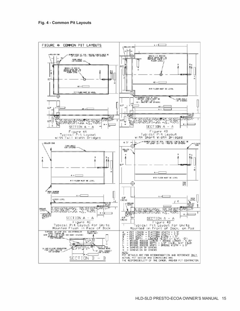
RECOMMENDED PIT LAYOUTA general layout for a typical pit mounted SizzrDok loading dock is shown in Figure 1. Figure 2 shows some typical layouts for the SizzrDok. The 8’’ diameter bumper posts, shown in various details, are strongly recommended. They prevent damage to the SizzrDok loading dock by pre-venting a truck from accidentally backing into a raised or partially raised lift. Lift specifications are detailed in Figure 3 and various pit layouts are shown in Figure 4.
GENERAL NOTES SUPPLIED BY OWNER OR CONTRACTOR
1. Provide 3’’ dia. conduit with 12’’ minimum radius bends from Power Unit location to lift pit. As shown in Figure 4, the conduit entry should be to the clevis (end opposite to cylinders) end of the lift installation.
2. Provide hydraulic hose or ASA steel tubing and fittings (minimum bursting pressure 9000 PSI) from the power unit location into the hinge end of the lift pit. For proper connection to the power unit and lift, the hose must have a # 8 SAE 37˚ Flare female fitting on both ends. Size and con-struction of the hose should be as follows:
(a) For hose lengths up to 50 feet, use 3/8’’ ID hydraulic hose(b) For hose lengths greater than 50 feet, use ½” ID hydraulic hose
3. Provide ¼” OD polypropylene or nylon tubing from power unit location to lift pit (if required).
4. If the optional limit switch is purchased, provide a #16 AWG 2-wire conductor (type SO) from the control box to the limit switch located within the lift base frame.
5. Ensure the concrete is reinforced to suit local soil conditions. All pit construction including the bumper posts, curb angles, conduit, hydraulic oil, hydraulic connections and electrical hook-up are the responsibility of the owner or the pit contractor.
6. Pit drains are to be installed to suit local code and weather conditions.
7. Install the bumper posts (provided by others) on all pits, as detailed in Figures 4A, 4B and 4D.
8. Service wiring and/or relocation of the power unit controls are the responsibility of the contrac-tor and/or the owner.
It must be clearly noted that the sole purpose of the drawings (Figures 4A through 4D) is to docu-ment the configuration of the equipment built by Presto-ECOA and any specific installation data pertinent to the satisfactory operation thereof. It is not the Intent of Presto-ECOA to provide instal-lation details such as concrete thickness and reinforcing, routing of electrical and hydraulic lines, component location and orientation, position of adjacent structures, etc., but rather, to make final construction drawings for the specific job requirement.
Pit details and dimensions are for recommendation and reference only. Actual pit design, dimen-sions, and specifications, are the responsibility of the owner and/or pit contractor.Presto-Ecoa assumes no responsibility, liability, or warranty considerations, for incorrect, faulty, or defective pit construction.
HLD-SLD PRESTO-ECOA OWNER’S MANUAL 13
FIG 2. - General Layout
14 HLD-SLD PRESTO-ECOA OWNER’S MANUAL
Fig. 3 - General Specifications
HLD-SLD PRESTO-ECOA OWNER’S MANUAL 15
Fig. 4 - Common Pit Layouts
16 HLD-SLD PRESTO-ECOA OWNER’S MANUAL
OPERATING INSTRUCTIONS The load capacity rating as stamped on the nameplate of your SizzrDok designates the maxi-mum lifting capacity with a uniformly distributed load. This capacity must never be exceeded, as permanent damage may result. Lifting loads that exceed the rated capacity will result in excessive wear or damage to the lift.
The axle load capacities must be derated for cases where the lift platform is modified in the field. Consult the factory before any modification is performed in the field.
The SizzrDok is furnished with constant pressure (“dead-man” type) push button controls. Press-ing the ‘’UP’’ (or RAISE) button, starts the motor, (see wiring diagram) which in turn runs the hy-draulic pump. The cylinders begin to extend and the platform starts to rise. The platform will rise as long as the ‘’UP’’ button is pressed. On releasing the button, the platform ceases to rise and will remain at that particular elevation.
When pressing the “DOWN” button, the Down Solenoid Valve is energized. The cylinders start retracting as the oil returns to the reservoir and, upon releasing the button, the platform ceases to lower, remaining at that particular elevation.
When the lift reaches its full vertical travel, the cylinders have extended to its maximum limit. The platform will no longer travel up due to the internal stops in the cylinders. At this point the relief valve will open because of pressure build up and oil will bypass into the reservoir. Do not continue to operate the lift as it will create excessive wear on the pump.
In the event that the lift is overloaded, the relief valve will open because of excessive pressure build up, and oil will bypass into the reservoir. When the lift reaches a preset vertical travel the ‘’up limit switch” (if purchased) will be actuated. This shuts off the power to the motor. At this point, pressing the ‘’UP’’ button will have no effect. The platform will remain stationary at the de-sired elevation.
Always remember that the motor runs only when the ‘’UP’’ button is pressed and the Down Sole-noid Valve is energized only when the ‘’DOWN’’ button is pressed.
Some “Tips” to the Operator
1. Always load the lift properly by centering the load on the platform as much as possible.
2. Never use the lift if it is in need of repairs, or in the case of a malfunction.
3. Notify your maintenance personnel if you notice anything out of the ordinary, such as bind-ing, odd pump noises, etc.
4. Do not continue to press the ‘’UP” button if the lift is not rising. You can permanently dam-age the motor or pump by doing so.
5. Ensure that handrails and chains are in place before operating the lift.
HLD-SLD PRESTO-ECOA OWNER’S MANUAL 17
ROUTINE MAINTENANCE
Raise the lift and engage the maintenance safety bars before beginning any inspection or work on the unit.
(A) Monthly Inspections
1. Check oil level, It should be about 1’’ below top of the tank with the lift in fully lowered posi-tion. Add oil as required. (See oil specifications.)
2. Check for oil leaks. See Trouble Shooting Section and correct as necessary.
3. Check roller bushings, axle pin, clevis and pivot points for wear.
4. Check for worn or damaged hydraulic hoses or electrical cords. Repair as necessary.
5. Check rollers for looseness and wear, See Trouble Shooting.
6. Check retaining rings at all axles, pivot points and clevis.
7. Never grease rollers or axles.
8. Check for unusual noise. See Trouble Shooting.
(B)Yearly InspectionOil in reservoir should be changed at least once a year, or sooner if the oil darkens or becomes gritty. Presence of water is indicated if the oil turns milky.
(C)Winter/Summer MaintenanceChange the oil as per ‘Oil Viscosity Recommendations’ depending on the ambient temperatures prevailing in your area.
18 HLD-SLD PRESTO-ECOA OWNER’S MANUAL
HYDRAULIC SECTIONWhen the operator wants to raise the platform, he or she presses the “UP” button. This starts the electric motor, which runs the hydraulic pump. Oil from the reservoir is sucked in through the suc-tion filter and into the pump. The pump delivers the pressurized oil into the valve block. The oil flows through the check valve before entering the cylinders. The function of the check valve is to allow the oil to flow in one direction i.e. towards the cylinders. It also prevents the flow of oil back into the pump circuit when the pump stops running. This holds the oil in the cylinders and main-tains the desired elevation.
If the load is excessive, and the ‘’UP’’ button is still pressed, pressure will build up in the circuit between the pump and the cylinders. This forces the ‘’ball’’ or ‘’poppet’’ in the relief valve to un-seat and the pump output returns into the reservoir through the return pipe.
When the operator desires to lower the lift, he or she presses the “DOWN” button. This energizes the down solenoid valve. The poppet in the solenoid valve is unseated and oil now returns from the cylinders through the flow control valve, the solenoid valve, the pressure-compensated spool valve, to the oil return pipe, and into the reservoir. The flow control valve controls the down speed of the lift. The pressure-compensated spool valve ensures that lowering speeds are nearly con-stant, regardless of load.
Releasing the “DOWN” button will de-energize the solenoid, closing the valve poppet. This pre-vents the oil from returning to the reservoir and the cylinders will stop retracting. The lift is now maintained at that particular elevation.
A flow limiter is installed at the base of each cylinder. In the event of a hydraulic hose failure, the platform lowers at a fast rate. As soon as the descent speed exceeds the preset speed, the flow limiter will shut off the oil flow and the platform will come down at a very slow speed until pressure is reapplied. This safety feature reduces the possibility of accidental personal injury or damage to the lift.
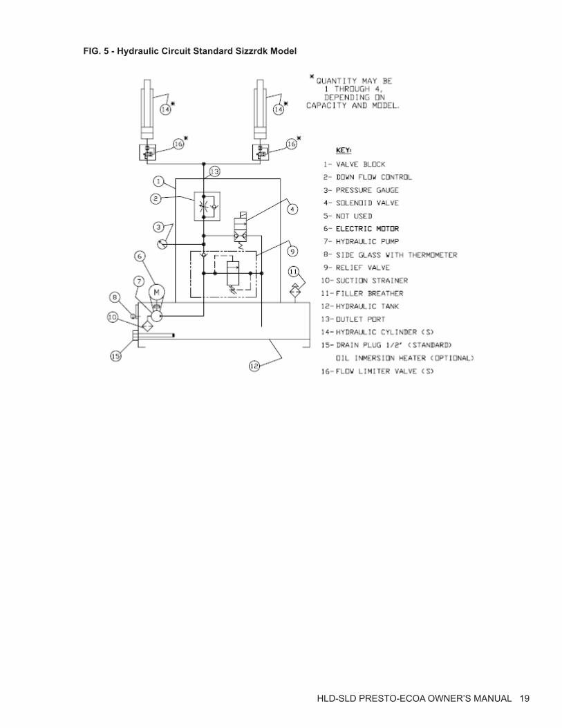
A complete Hydraulic Schematic is shown in Figure 5.
HLD-SLD PRESTO-ECOA OWNER’S MANUAL 19
FIG. 5 - Hydraulic Circuit Standard Sizzrdk Model
20 HLD-SLD PRESTO-ECOA OWNER’S MANUAL
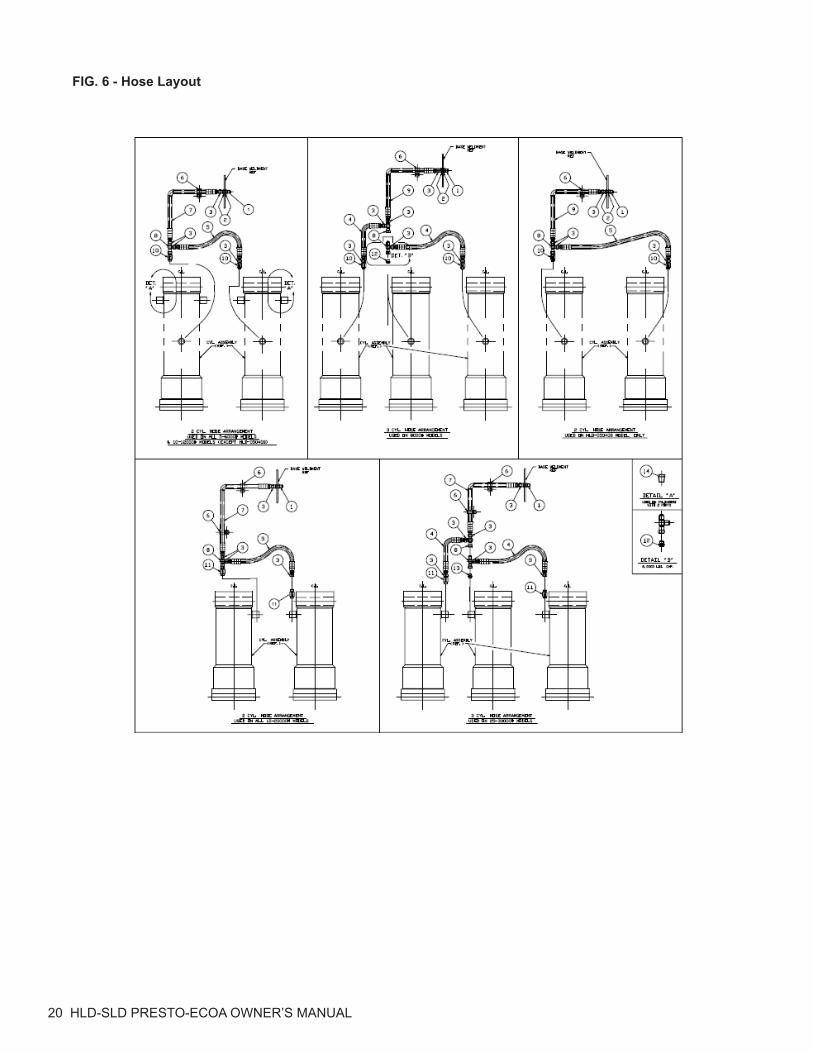
FIG. 6 - Hose Layout
HLD-SLD PRESTO-ECOA OWNER’S MANUAL 21
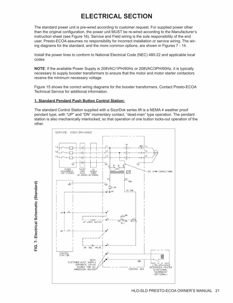
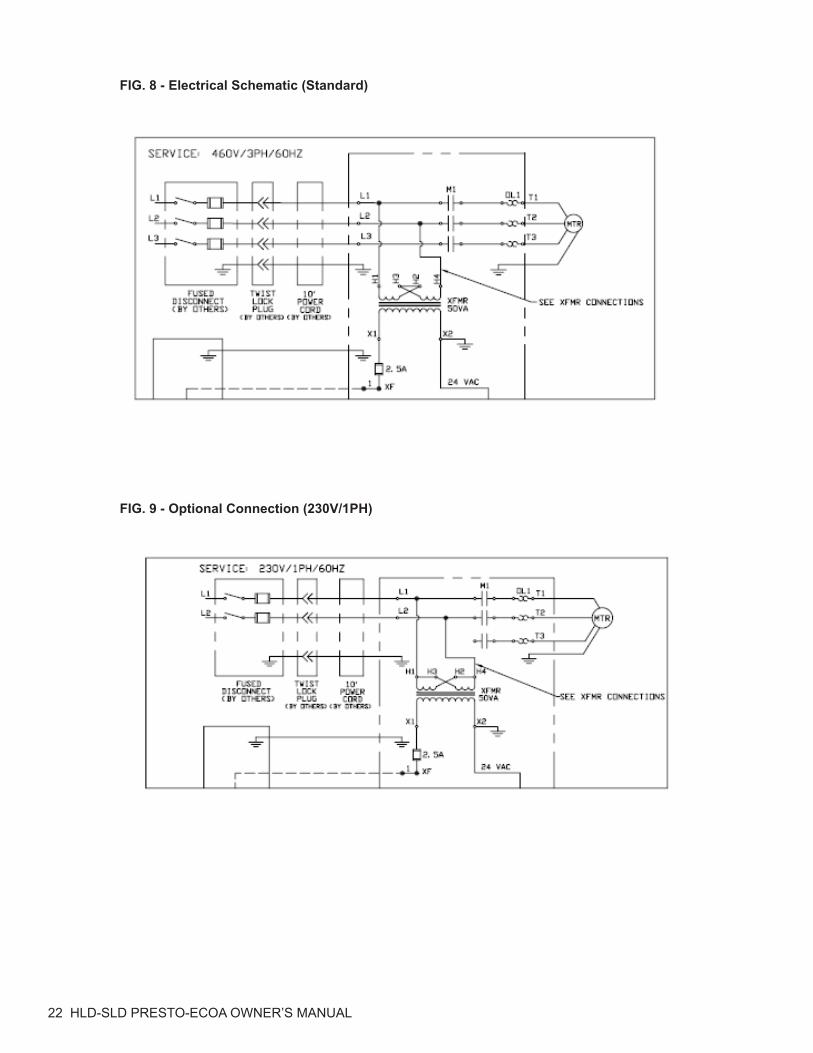
ELECTRICAL SECTIONThe standard power unit is pre-wired according to customer request. For supplied power other than the original configuration, the power unit MUST be re-wired according to the Manufacturer’s instruction sheet (see Figure 16). Service and Field wiring is the sole responsibility of the end user. Presto-ECOA assumes no responsibility for incorrect installation or service wiring. The wir-ing diagrams for the standard, and the more common options, are shown in Figures 7 - 14.
Install the power lines to conform to National Electrical Code (NEC) 480-22 and applicable local codes.
NOTE: If the available Power Supply is 208VAC/1PH/60Hz or 208VAC/3PH/60Hz, it is typically necessary to supply booster transformers to ensure that the motor and motor starter contactors receive the minimum necessary voltage.
Figure 15 shows the correct wiring diagrams for the booster transformers. Contact Presto-ECOA Technical Service for additional information.
1. Standard Pendant Push Button Control Station:
The standard Control Station supplied with a SizzrDok series lift is a NEMA 4 weather proof pendant type, with “UP” and “DN” momentary contact, “dead-man” type operation. The pendant station is also mechanically interlocked, so that operation of one button locks-out operation of the other.
FIG
. 7- E
lect
rical
Sch
emat
ic (S
tand
ard)
22 HLD-SLD PRESTO-ECOA OWNER’S MANUAL
FIG. 8 - Electrical Schematic (Standard)
FIG. 9 - Optional Connection (230V/1PH)
HLD-SLD PRESTO-ECOA OWNER’S MANUAL 23
24 HLD-SLD PRESTO-ECOA OWNER’S MANUAL
HLD-SLD PRESTO-ECOA OWNER’S MANUAL 25
ORDERING REPLACEMENT PARTS
Presto-ECOA Lifts has carefully chosen the components in your unit to be the best available for the purpose. Replacement parts should be identical to the original equipment. Presto-ECOA Lifts will not be responsible for equipment failures resulting from the use of incorrect replacement parts or from unauthorized modifications to the unit.
Presto-ECOA Lifts can supply all replacement parts for your lift. With your order, please include the model number and the serial number of the unit. You can find these numbers on the name plate. This plate is located within the scissors mechanism.
To order replacement parts, please call the Presto-ECOA Parts Department. Parts are shipped subject to the following terms:
• FOB factory
• Returns only with the approval of our parts department.
• Credit cards preferred (except parts covered by warranty).
• Freight collect for truck (except parts covered by warranty).
• Freight – prepaid and invoice for small parcel shipments (except parts covered by warranty).
• The warranty for repair parts is 30 days from date of shipment.
Parts replaced under warranty are on a “charge-credit” basis. We will invoice you when we ship the replacement part, then credit you when you return the worn or damaged part, and we verify that it is covered by our warranty. Labor is not covered under warranty for Parts orders.
Presto-ECOA Parts Department50 Commerce Way, Norton, MA 02766
Telephone: 800-343-9322FAX: 888-788-6496
Email: [email protected]

26 HLD-SLD PRESTO-ECOA OWNER’S MANUAL
Presto-ECOA LiftsLimited Warranty Policy
Presto-ECOA Lifts warrants all of its products against defects in the welded structural frame and, if applicable, scissor legs from faulty material and workmanship for a period of five years from the date of invoice.
All other components have a limited warranty against defects in faulty material and workmanship for a two year period from the date of invoice date of invoice and 30 day limited warranty on labor. Please note that prior authorization from Presto-ECOA Lifts is required on all warranty work.
There are no implied warranties of any kind, more specifically, there are no warranties of mer-chantability or fitness for any particular purpose. Presto-ECOA Lifts' sole warranty shall be as set forth in this limited warranty.
Presto-ECOA Lifts will elect to repair or replace a defective component without charge, if any components should become defective within the limited warranty period. Proof of purchase is required for warranty. The charge for shipping the defective component is the responsibility of the buyer and must be accompanied with an RMA number. The shipping charge to return the component to the buyer is the responsibility of Presto-ECOA Lifts.
This limited warranty does not cover labor expense for removal or reinstallation of components after thirty days. This limited warranty shall not cover, among other things: damages result-ing from foreign matter or water, failure to provide reasonable and necessary maintenance, and if applicable, use of product while charger is plugged into an AC outlet, or failure to follow operating instructions. The limited warranty is not valid for damage resulting from negligence, accident, unreasonable use, abuse or misuse, exceeding data plate capacities or altering the product without Presto-ECOA Lifts authorization.
Presto-ECOA Lifts expressly disclaims and excludes any liability for consequential, incidental, indirect or punitive damages or financial loss to people or property resulting from any breach of warranty or the operation or failure of this product.
Presto-ECOA Lifts makes no representation that this product complies with local, state, or fed-eral safety/product standards codes. Should this product fail to comply in any way with those codes, it shall not be considered a defect of materials or workmanship. Presto-ECOA Lifts shall not be held liable for any damages resulting from noncompliance. It is the dealer's responsibil-ity to exercise this limited warranty. This limited warranty is provided to the original purchaser (defined as the original end user) and is nontransferable. This constitutes the complete and final agreement involving Presto-ECOA Lifts limited warranty obligations for products.