HITACHI SPECTROPHOTOMETER Measurement … · Measurement system for liquid samples A U-4100 solid...
11
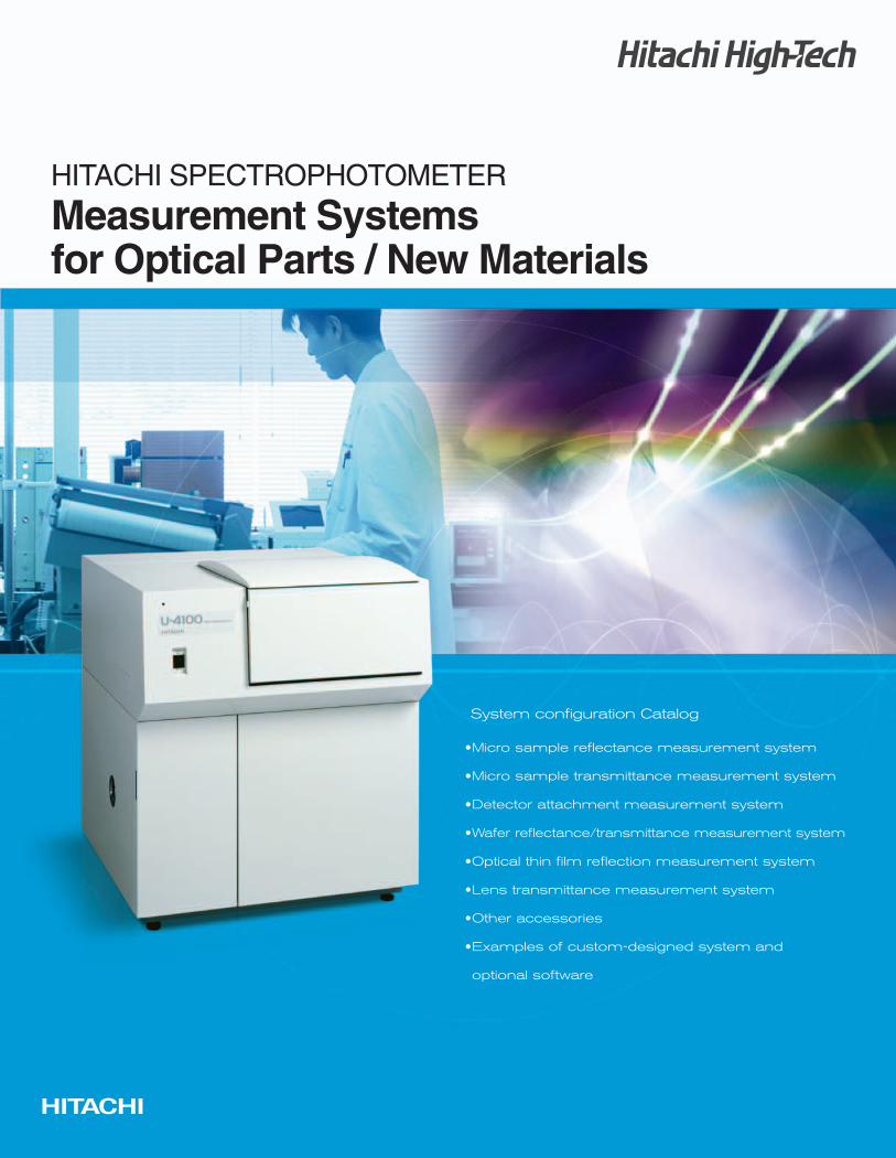
HITACHI SPECTROPHOTOMETER Measurement Systems for Optical Parts / New Materials
Transcript of HITACHI SPECTROPHOTOMETER Measurement … · Measurement system for liquid samples A U-4100 solid...
HITACHI SPECTROPHOTOMETER
Measurement Systems for Optical Parts / New Materials
1
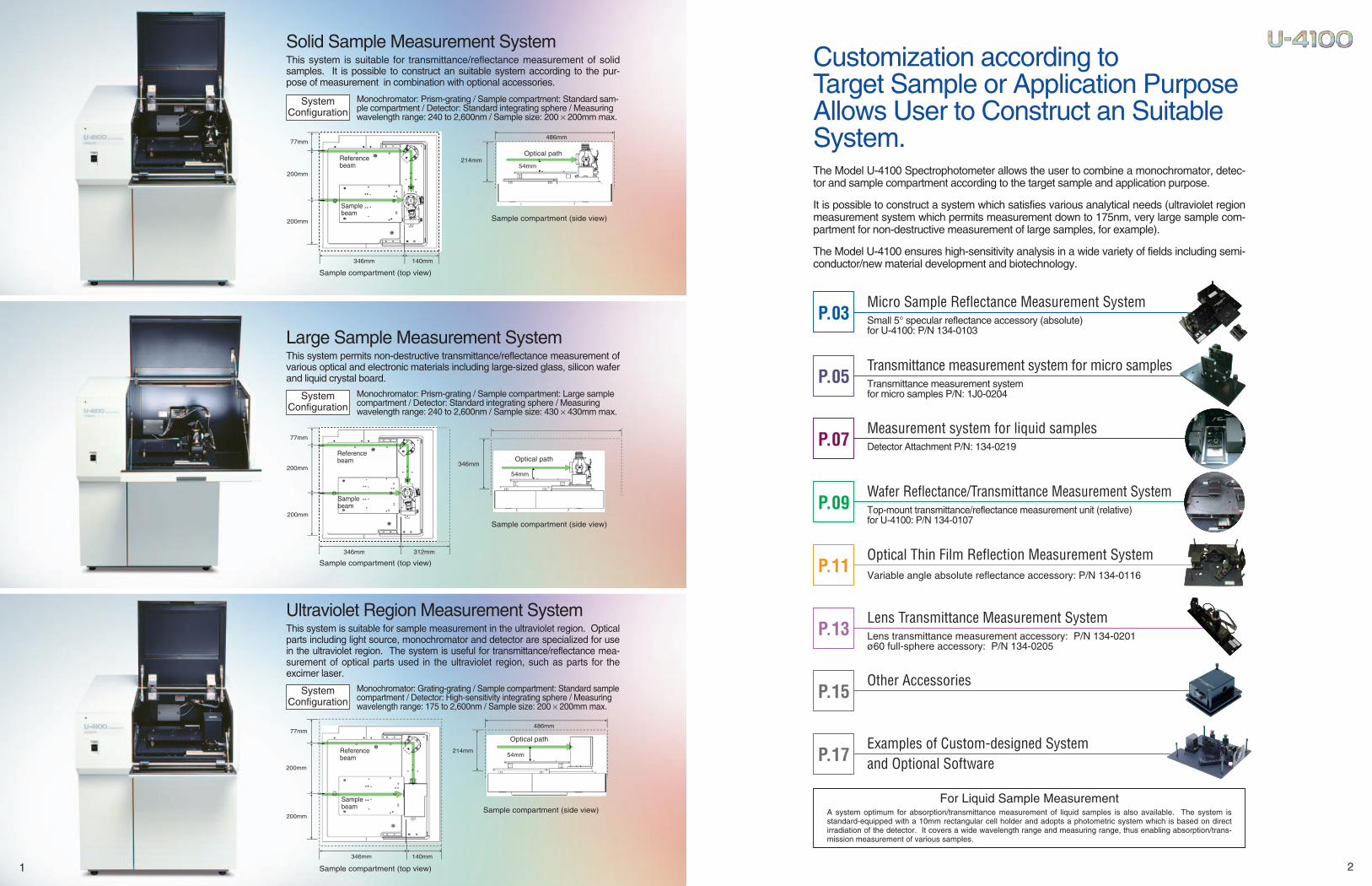
Solid Sample Measurement System This system is suitable for transmittance/reflectance measurement of solidsamples. It is possible to construct an suitable system according to the pur-pose of measurement in combination with optional accessories.
SystemConfiguration
Monochromator: Prism-grating / Sample compartment: Standard sam-ple compartment / Detector: Standard integrating sphere / Measuringwavelength range: 240 to 2,600nm / Sample size: 200 × 200mm max.
77mm
200mm
200mm
346mm 140mm
Reference beam
Sample beam
Sample compartment (top view)
214mm
486mm
54mm
Optical path
Sample compartment (side view)
Large Sample Measurement SystemThis system permits non-destructive transmittance/reflectance measurement ofvarious optical and electronic materials including large-sized glass, silicon waferand liquid crystal board.
SystemConfiguration
Monochromator: Prism-grating / Sample compartment: Large samplecompartment / Detector: Standard integrating sphere / Measuringwavelength range: 240 to 2,600nm / Sample size: 430 × 430mm max.
Sample compartment (top view)
Sample compartment (side view)
346mm
54mm
77mm
200mm
200mm
346mm 312mm
Reference beam
Sample beam
Optical path
Ultraviolet Region Measurement SystemThis system is suitable for sample measurement in the ultraviolet region. Opticalparts including light source, monochromator and detector are specialized for usein the ultraviolet region. The system is useful for transmittance/reflectance mea-surement of optical parts used in the ultraviolet region, such as parts for theexcimer laser.
SystemConfiguration
Monochromator: Grating-grating / Sample compartment: Standard samplecompartment / Detector: High-sensitivity integrating sphere / Measuringwavelength range: 175 to 2,600nm / Sample size: 200 × 200mm max.
Sample compartment (top view)
Sample compartment (side view)
77mm
200mm
200mm
346mm 140mm
214mm54mm
486mm
Reference beam
Sample beam
Optical path
2
Customization according toTarget Sample or Application PurposeAllows User to Construct an SuitableSystem.The Model U-4100 Spectrophotometer allows the user to combine a monochromator, detec-tor and sample compartment according to the target sample and application purpose.
It is possible to construct a system which satisfies various analytical needs (ultraviolet regionmeasurement system which permits measurement down to 175nm, very large sample com-partment for non-destructive measurement of large samples, for example).
The Model U-4100 ensures high-sensitivity analysis in a wide variety of fields including semi-conductor/new material development and biotechnology.
Micro Sample Reflectance Measurement SystemSmall 5° specular reflectance accessory (absolute) for U-4100: P/N 134-0103
P.03
Transmittance measurement system for micro samplesTransmittance measurement system for micro samples P/N: 1J0-0204
P.05
Wafer Reflectance/Transmittance Measurement SystemTop-mount transmittance/reflectance measurement unit (relative) for U-4100: P/N 134-0107
P.09
Optical Thin Film Reflection Measurement SystemVariable angle absolute reflectance accessory: P/N 134-0116
P.11
Lens Transmittance Measurement SystemLens transmittance measurement accessory: P/N 134-0201ø60 full-sphere accessory: P/N 134-0205
P.13
Other AccessoriesP.15
Examples of Custom-designed System and Optional SoftwareP.17
Measurement system for liquid samples Detector Attachment P/N: 134-0219P.07
For Liquid Sample MeasurementA system optimum for absorption/transmittance measurement of liquid samples is also available. The system isstandard-equipped with a 10mm rectangular cell holder and adopts a photometric system which is based on directirradiation of the detector. It covers a wide wavelength range and measuring range, thus enabling absorption/trans-mission measurement of various samples.
3
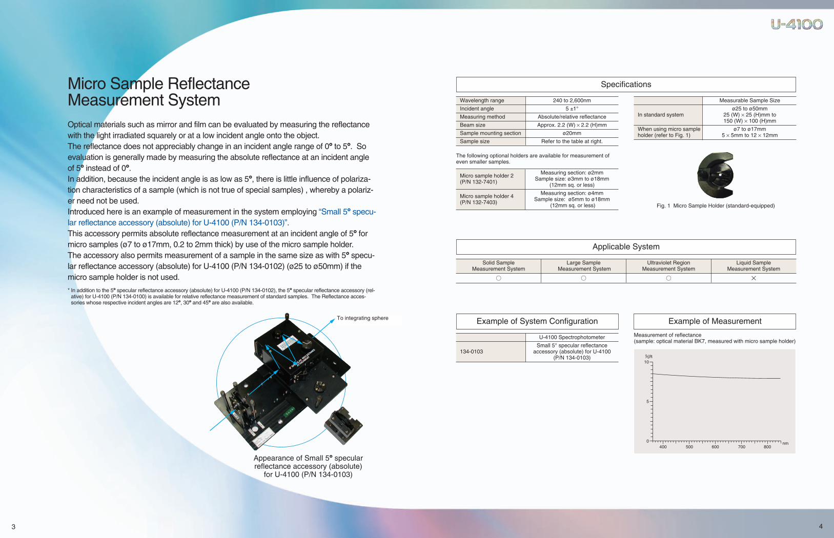
Micro Sample Reflectance Measurement SystemOptical materials such as mirror and film can be evaluated by measuring the reflectancewith the light irradiated squarely or at a low incident angle onto the object.The reflectance does not appreciably change in an incident angle range of 0° to 5°. Soevaluation is generally made by measuring the absolute reflectance at an incident angleof 5° instead of 0°.In addition, because the incident angle is as low as 5°, there is little influence of polariza-tion characteristics of a sample (which is not true of special samples) , whereby a polariz-er need not be used.Introduced here is an example of measurement in the system employing “Small 5° specu-lar reflectance accessory (absolute) for U-4100 (P/N 134-0103)”.This accessory permits absolute reflectance measurement at an incident angle of 5° formicro samples (ø7 to ø17mm, 0.2 to 2mm thick) by use of the micro sample holder.The accessory also permits measurement of a sample in the same size as with 5° specu-lar reflectance accessory (absolute) for U-4100 (P/N 134-0102) (ø25 to ø50mm) if themicro sample holder is not used.
* In addition to the 5° specular reflectance accessory (absolute) for U-4100 (P/N 134-0102), the 5° specular reflectance accessory (rel-ative) for U-4100 (P/N 134-0100) is available for relative reflectance measurement of standard samples. The Reflectance acces-sories whose respective incident angles are 12°, 30° and 45° are also available.
Appearance of Small 5° specular reflectance accessory (absolute)
for U-4100 (P/N 134-0103)
To integrating sphere
4
400 500 600 700 8000
5
10%R
nm
Wavelength range 240 to 2,600nm
Incident angle 5 ±1°
Measuring method Absolute/relative reflectance
Beam size Approx. 2.2 (W) × 2.2 (H)mm
Sample mounting section ø20mm
Sample size Refer to the table at right.
The following optional holders are available for measurement ofeven smaller samples.
Micro sample holder 2 Measuring section: ø2mm
(P/N 132-7401) Sample size: ø3mm to ø18mm (12mm sq. or less)
Micro sample holder 4 Measuring section: ø4mm
(P/N 132-7403) Sample size: ø5mm to ø18mm(12mm sq. or less) Fig. 1 Micro Sample Holder (standard-equipped)
Measurable Sample Size
ø25 to ø50mmIn standard system 25 (W) × 25 (H)mm to
150 (W) × 100 (H)mm
When using micro sample ø7 to ø17mmholder (refer to Fig. 1) 5 × 5mm to 12 × 12mm
Specifications
Applicable System
U-4100 Spectrophotometer
Small 5° specular reflectance 134-0103 accessory (absolute) for U-4100
(P/N 134-0103)
Example of System Configuration
Measurement of reflectance(sample: optical material BK7, measured with micro sample holder)
Example of Measurement
Solid Sample Large Sample Ultraviolet Region Liquid SampleMeasurement System Measurement System Measurement System Measurement System
○ ○ ○ ×
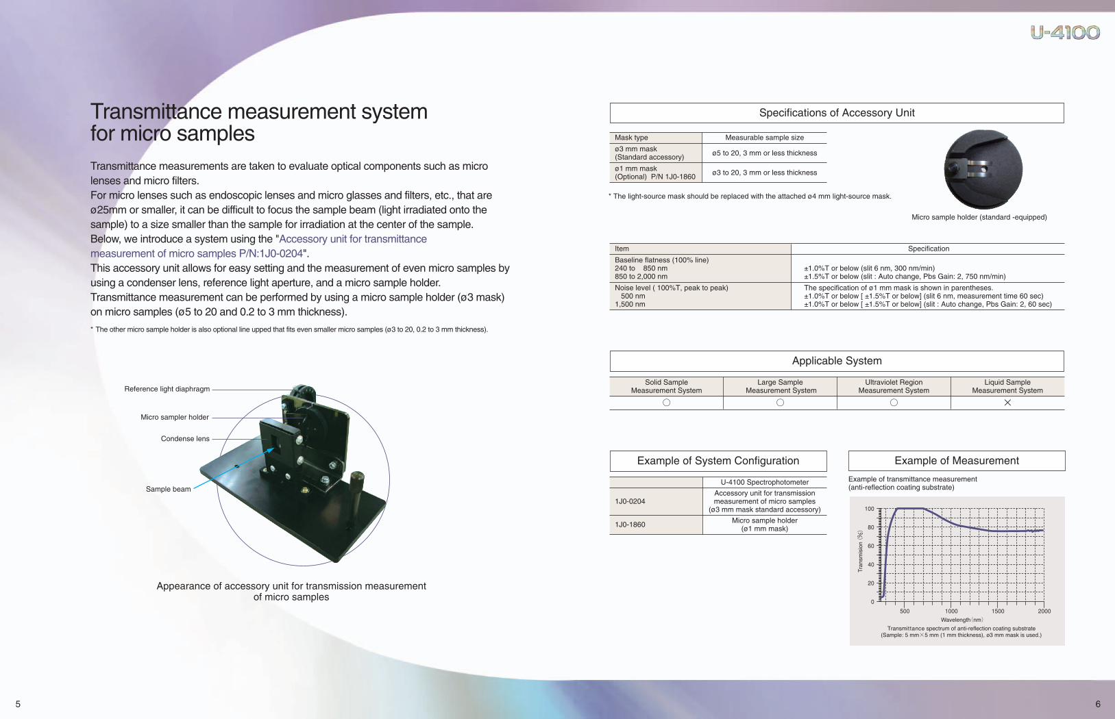
Transmittance measurement system for micro samplesTransmittance measurements are taken to evaluate optical components such as microlenses and micro filters.For micro lenses such as endoscopic lenses and micro glasses and filters, etc., that areø25mm or smaller, it can be difficult to focus the sample beam (light irradiated onto thesample) to a size smaller than the sample for irradiation at the center of the sample.Below, we introduce a system using the "Accessory unit for transmittancemeasurement of micro samples P/N:1J0-0204".This accessory unit allows for easy setting and the measurement of even micro samples byusing a condenser lens, reference light aperture, and a micro sample holder.Transmittance measurement can be performed by using a micro sample holder (ø3 mask)on micro samples (ø5 to 20 and 0.2 to 3 mm thickness).
* The other micro sample holder is also optional line upped that fits even smaller micro samples (ø3 to 20, 0.2 to 3 mm thickness).
5
Appearance of accessory unit for transmission measurement of micro samples
Reference light diaphragm
Micro sampler holder
Condense lens
Sample beam
Specifications of Accessory Unit
Mask type Measurable sample size
ø3 mm mask ø5 to 20, 3 mm or less thickness(Standard accessory)
ø1 mm mask ø3 to 20, 3 mm or less thickness(Optional) P/N 1J0-1860
Item Specification
Baseline flatness (100% line)240 to 850 nm ±1.0%T or below (slit 6 nm, 300 nm/min)850 to 2,000 nm ±1.5%T or below (slit : Auto change, Pbs Gain: 2, 750 nm/min)
Noise level ( 100%T, peak to peak) The specification of ø1 mm mask is shown in parentheses.500 nm ±1.0%T or below [ ±1.5%T or below] (slit 6 nm, measurement time 60 sec)
1,500 nm ±1.0%T or below [ ±1.5%T or below] (slit : Auto change, Pbs Gain: 2, 60 sec)
6
Applicable System
Solid Sample Large Sample Ultraviolet Region Liquid SampleMeasurement System Measurement System Measurement System Measurement System
○ ○ ○ ×
Micro sample holder (standard -equipped)
U-4100 Spectrophotometer
Accessory unit for transmission 1J0-0204 measurement of micro samples
(ø3 mm mask standard accessory)
1J0-1860 Micro sample holder (ø1 mm mask)
Example of System Configuration
Example of transmittance measurement(anti-reflection coating substrate)
Example of Measurement
* The light-source mask should be replaced with the attached ø4 mm light-source mask.

Measurement system for liquid samples A U-4100 solid sample measurement system or a large sample measurement system isused; thus, when a liquid sample with a narrow bandpass and less noise needs to be mea-sured, use of an integrating sphere has limitations.Here, we introduce the "Detector attachment P/N:134-0219".This accessory unit provides a large wavelength range (185 to 3,300 nm) and a large mea-surement range by changing the integrating sphere into optical measurement through useof the detector's normal incidence, which can measure the absorption/transmission of awide range of samples.
* For use of cells other than 10 mm rectangular cells, please use a another cell holder.
7
Appearance of detector attachment
10 mm rectangular cell holder
Sample beam
8
Specifications of Accessory Unit
U-4100 spectrophotometer
134-0219 Detector attachment
Example of System Configuration Example of Measurement
Item Specification
Wavelength range 185 to 3,300 nm
Corresponding cell 10 mm square cell (prepared separately)
Stray light NaI 220 nm ≤0.00008%NaNo2 340 nm ≤0.00005%Chloroform 1,690 nm ≤0.025%
Baseline flatness (0Abs line) <Measuring conditions>185 to 200 nm ±0.05Abs or below200 to 850 nm ±0.001Abs or below850 to 2,500 nm ±0.002Abs or below2,500 to 3,300 nm ±0.004Abs or below
Noise level (0Abs,RMS)500 nm 0.00004Abs or below2,000 nm 0.00003Abs or below
Applicable System
Solid Sample Large Sample Ultraviolet Region Liquid SampleMeasurement System Measurement System Measurement System Measurement System
○ ○ ○ ×
Slit: 2 nm (UV-VIS), auto change (NIR), sampling interval: auto, Scanspeed: 300 nm/min (UV-VIS), 750 nm/min (NIR)Measurement is conducted after user baseline correction (at 2 hours ormore after power-on). Absorption wavelength of water, detector switchingwavelength, and light-source switching wavelength are excluded.
<Measuring conditions>Slit: 2 nm (UV-VIS), auto change (NIR), scan time: 60 s, sampling interval:1s (excluding drift).
*Additional installation to the existing U-4100 type is made at additional expense.
Measurement of a liquid sample (hexavalent chrome)
9
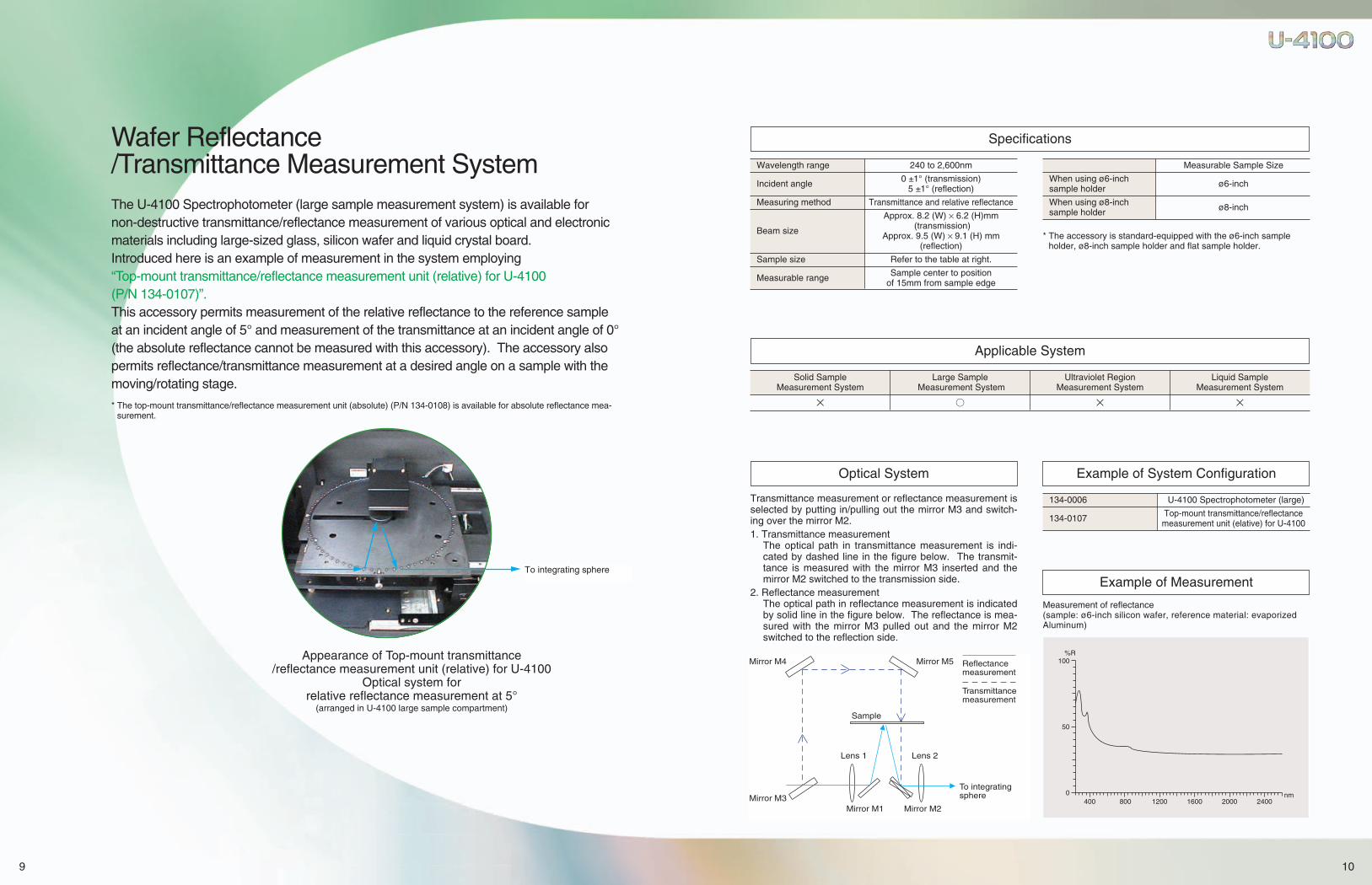
Wafer Reflectance/Transmittance Measurement SystemThe U-4100 Spectrophotometer (large sample measurement system) is available for non-destructive transmittance/reflectance measurement of various optical and electronicmaterials including large-sized glass, silicon wafer and liquid crystal board.Introduced here is an example of measurement in the system employing “Top-mount transmittance/reflectance measurement unit (relative) for U-4100 (P/N 134-0107)”.This accessory permits measurement of the relative reflectance to the reference sampleat an incident angle of 5° and measurement of the transmittance at an incident angle of 0°(the absolute reflectance cannot be measured with this accessory). The accessory alsopermits reflectance/transmittance measurement at a desired angle on a sample with themoving/rotating stage.
* The top-mount transmittance/reflectance measurement unit (absolute) (P/N 134-0108) is available for absolute reflectance mea-surement.
Appearance of Top-mount transmittance/reflectance measurement unit (relative) for U-4100
Optical system for relative reflectance measurement at 5°
(arranged in U-4100 large sample compartment)
To integrating sphere
10
400 800 1200 1600 2000 24000
50
100%R
nm
Wavelength range 240 to 2,600nm
Incident angle 0 ±1° (transmission)5 ±1° (reflection)
Measuring method Transmittance and relative reflectance
Approx. 8.2 (W) × 6.2 (H)mm
Beam size (transmission)Approx. 9.5 (W) × 9.1 (H) mm
(reflection)
Sample size Refer to the table at right.
Measurable range Sample center to position of 15mm from sample edge
Measurable Sample Size
When using ø6-inch sample holder ø6-inch
When using ø8-inch sample holder ø8-inch
* The accessory is standard-equipped with the ø6-inch sampleholder, ø8-inch sample holder and flat sample holder.
Specifications
Applicable System
Transmittance measurement or reflectance measurement isselected by putting in/pulling out the mirror M3 and switch-ing over the mirror M2.1. Transmittance measurement
The optical path in transmittance measurement is indi-cated by dashed line in the figure below. The transmit-tance is measured with the mirror M3 inserted and themirror M2 switched to the transmission side.
2. Reflectance measurementThe optical path in reflectance measurement is indicatedby solid line in the figure below. The reflectance is mea-sured with the mirror M3 pulled out and the mirror M2switched to the reflection side.
Optical System
134-0006 U-4100 Spectrophotometer (large)
134-0107 Top-mount transmittance/reflectance measurement unit (elative) for U-4100
Example of System Configuration
Measurement of reflectance(sample: ø6-inch silicon wafer, reference material: evaporizedAluminum)
Example of Measurement
Solid Sample Large Sample Ultraviolet Region Liquid SampleMeasurement System Measurement System Measurement System Measurement System
× ○ × ×
Mirror M4 Mirror M5
Sample
Lens 1 Lens 2
Mirror M3Mirror M1 Mirror M2
Reflectance measurement
Transmittance measurement
To integrating sphere
11
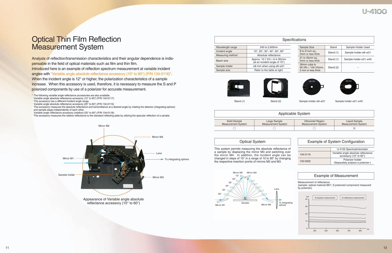
Optical Thin Film Reflection Measurement SystemAnalysis of reflection/transmission characteristics and their angular dependence is indis-pensable in the field of optical materials such as film and thin film.Introduced here is an example of reflection spectrum measurement at variable incidentangles with “Variable angle absolute reflectance accessory (10° to 60°) (P/N 134-0116)”.When the incident angle is 12° or higher, the polarization characteristics of a sampleincrease. When this accessory is used, therefore, it is necessary to measure the S and Ppolarized components by use of a polarizer for accurate measurement.
* The following variable angle reflectance accessories are also available.Variable angle absolute reflectance accessory (15° to 65°) (P/N 134-0117):This accessory has a different incident angle range.Variable angle absolute reflectance accessory (20° to 60°) (P/N 134-0115):This accessory measures the absolute reflectance and transmittance at a desired angle by rotating the detector (integrating sphere) and sample stage independently of each other.Variable angle reflectance accessory (relative) (20° to 60°) (P/N 134-0118):This accessory measures the relative reflectance to the standard reflecting plate by utilizing the specular reflection of a sample.
Appearance of Variable angle absolutereflectance accessory (10° to 60°)
Mirror M2
Mirror M1
Sample holder
Mirror M4
Lens
To integrating sphere
Mirror M3
12
Wavelength range 240 to 2,600nm
Incident angle 10°, 20°, 30°, 40°, 50°, 60°
Measuring method Absolute reflectance
Beam size Approx. 10.7 (H) × 6.4 (W)mm(at an incident angle of 10°)
Sample holder ø8 mm when using ø8–ø21
Sample size Refer to the table at right.
Stand (1)
Sample Size Stand Sample Holder Used
8 to 21mm sq., 5mm or less thick Stand (1) Sample holder ø8–ø21
21 to 45mm sq., 5mm or less thick Stand (1) Sample holder ø21–ø45
30mm cube to 90 (W) × 100 (H)mm, Stand (2) –5 mm or less thick
Stand (2) Sample holder ø8–ø21 Sample holder ø21–ø45
Specifications
Applicable System
Solid Sample Large Sample Ultraviolet Region Liquid SampleMeasurement System Measurement System Measurement System Measurement System
○ ○ ○ ×
400 500 600 700 800nm0
10
20
30
40%R
At reflectance measurementAt baseline measurement
This system permits measuring the absolute reflectance ofa sample by displacing the mirror M3 and switching overthe mirror M4. In addition, the incident angle can bechanged in steps of 10° in a range of 10 to 60° by changingthe respective insertion points of mirrors M2 and M3.
Optical System
U-4100 Spectrophotometer
134-0116 Variable angle absolute reflectance accessory (10° to 60°)
132-0325 Polarizer holder (Separately prepare a polarizer.)
Example of System Configuration
Measurement of reflectance(sample: optical material BK7, S polarized component measuredby polarizer)
Example of Measurement
To integrating sphere
10°20°
30°40°
50°
60°
Mirror M1
Mirror M2 Mirror M3
Lens
Mirror M4Sample
13
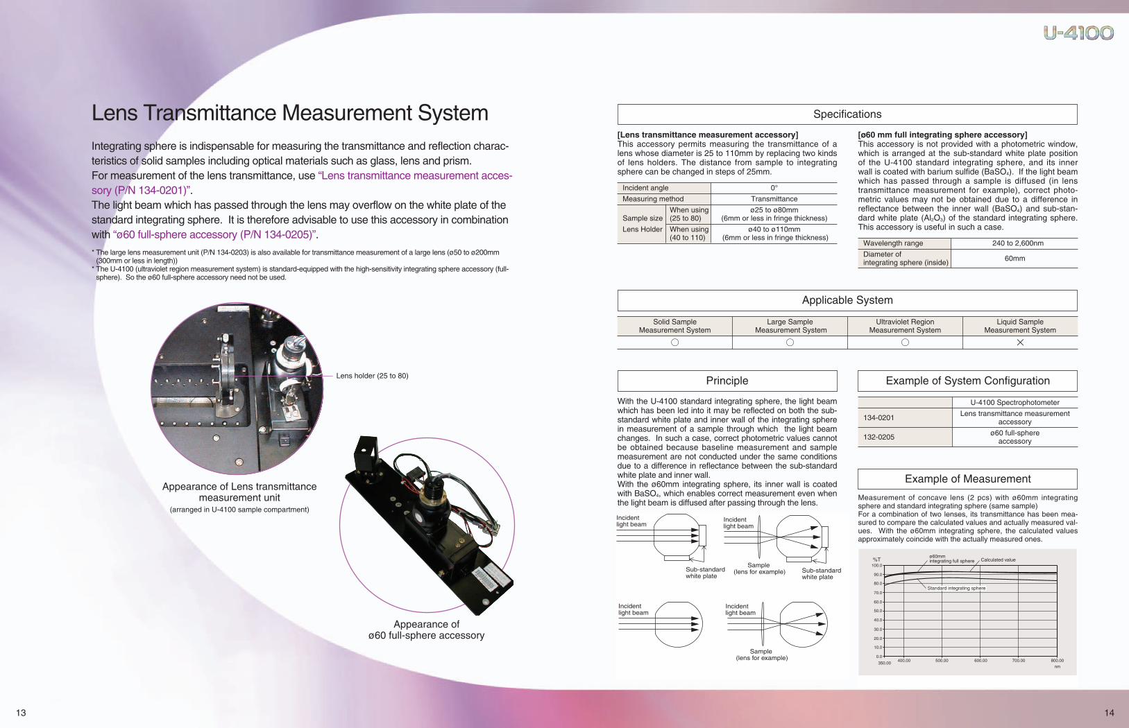
Lens Transmittance Measurement SystemIntegrating sphere is indispensable for measuring the transmittance and reflection charac-teristics of solid samples including optical materials such as glass, lens and prism.For measurement of the lens transmittance, use “Lens transmittance measurement acces-sory (P/N 134-0201)”.The light beam which has passed through the lens may overflow on the white plate of thestandard integrating sphere. It is therefore advisable to use this accessory in combinationwith “ø60 full-sphere accessory (P/N 134-0205)”.
* The large lens measurement unit (P/N 134-0203) is also available for transmittance measurement of a large lens (ø50 to ø200mm(300mm or less in length))
* The U-4100 (ultraviolet region measurement system) is standard-equipped with the high-sensitivity integrating sphere accessory (full-sphere). So the ø60 full-sphere accessory need not be used.
Appearance of Lens transmittancemeasurement unit
(arranged in U-4100 sample compartment)
Appearance of ø60 full-sphere accessory
Lens holder (25 to 80)
14
Incident angle 0°
Measuring method Transmittance
When using ø25 to ø80mm Sample size (25 to 80) (6mm or less in fringe thickness)
Lens Holder When using ø40 to ø110mm(40 to 110) (6mm or less in fringe thickness)
Wavelength range 240 to 2,600nm
Diameter of integrating sphere (inside) 60mm
Specifications
Applicable System
Solid Sample Large Sample Ultraviolet Region Liquid SampleMeasurement System Measurement System Measurement System Measurement System
○ ○ ○ ×
ø60mm integrating full sphere Calculated value
Standard integrating sphere
0.0
10.0
20.0
30.0
40.0
50.0
60.0
70.0
80.0
90.0
100.0
350.00400.00 500.00 600.00 700.00 800.00
nm
%T
With the U-4100 standard integrating sphere, the light beamwhich has been led into it may be reflected on both the sub-standard white plate and inner wall of the integrating spherein measurement of a sample through which the light beamchanges. In such a case, correct photometric values cannotbe obtained because baseline measurement and samplemeasurement are not conducted under the same conditionsdue to a difference in reflectance between the sub-standardwhite plate and inner wall.With the ø60mm integrating sphere, its inner wall is coatedwith BaSO4, which enables correct measurement even whenthe light beam is diffused after passing through the lens.
[Lens transmittance measurement accessory]This accessory permits measuring the transmittance of alens whose diameter is 25 to 110mm by replacing two kindsof lens holders. The distance from sample to integratingsphere can be changed in steps of 25mm.
[ø60 mm full integrating sphere accessory]This accessory is not provided with a photometric window,which is arranged at the sub-standard white plate positionof the U-4100 standard integrating sphere, and its innerwall is coated with barium sulfide (BaSO4). If the light beamwhich has passed through a sample is diffused (in lenstransmittance measurement for example), correct photo-metric values may not be obtained due to a difference inreflectance between the inner wall (BaSO4) and sub-stan-dard white plate (Al2O3) of the standard integrating sphere.This accessory is useful in such a case.
Principle
U-4100 Spectrophotometer
134-0201 Lens transmittance measurement accessory
132-0205 ø60 full-sphere accessory
Example of System Configuration
Measurement of concave lens (2 pcs) with ø60mm integratingsphere and standard integrating sphere (same sample)For a combination of two lenses, its transmittance has been mea-sured to compare the calculated values and actually measured val-ues. With the ø60mm integrating sphere, the calculated valuesapproximately coincide with the actually measured ones.
Example of Measurement
Incident light beam
Sample (lens for example)
Incident light beam
Sub-standardwhite plate
Incident light beam
Incident light beam
Sub-standardwhite plate
Sample (lens for example)

15
A Full Array of Other Optional Accessories toSupport the Diversified Measurement Needs
Sample size Relative reflectance measurement:
25 × 25mm to 100 × 15mm
Wavelength range 240 to 2,600nm
This unit measures the transmittance/reflectance of a microprism.
Incident angle 45°
Sample size 5 to 6mm cube, 7 to 20mm cube
Wavelength range 240 to 2,600nm
Common Specifications
Sample size Absolute reflectance measurement:25 × 25mm to 100 × 150mm
Wavelength range 240 to 2,600nm
These accessories measure the absolute reflectance of asample by the V-N method. They are used for obtaining thereflection characteristics of metallic film and glass surfacesaccording to the incident angle.Be sure to use them in combination with a polarizer.They are designed to set a sample on the side.
5° specular reflectance accessory(absolute) 134-0102
12° specular reflectance accessory(absolute) 134-0104
45° specular reflectance accessory(absolute) 134-0106
30° specular reflectance accessory(absolute) 134-0105
5° specular reflectance accessory(relative) for U-4100 134-0100 Small prism measurement unit 134-0111
16
This accessory is sensitive in the ultraviolet region. It is useful fortransmittance/reflectance evaluation of optical parts used in theultraviolet region, such as parts for the excimer laser.
Wavelength range 190 to 2,600nm
Detector Full sphere (with R955 photomultiplier)
100%T line flatness ±0.5%T (195 to 850nm)±2.0%T (190 to 195nm)
These accessories measure the absolute reflectance of a sampleby the V-N method with the mirror inserted at a specified position.
Incident angle 134-0116: 10° to 60° (in 10° steps)134-0117: 15° to 65° (in 10° steps)
Sample size 8 × 8mm to 90 × 100mm
Wavelength range 240 to 2,600nm
132-0325
Variable angle absolute reflectanceaccessory (15° to 65°) 134-0117
134-0116
High-sensitivity integrating sphere accessory 134-0206
Polarizer holder for U-4100(polarizer not included)
This accessory permits transmittance at a desired incident angle (0to 60°) by use of the rotating stage.
Incident angle 0° to 60°
Beam size Approx. 12.3 (H) × 8.5 (W)mm
Wavelength range 240 to 2,600nm
Sample size 40 × 40mm to 140 × 140mm, 3mm or less thick
Variable angle transmittance measurement accessory 134-0200
This accessory measures the absolute reflectance and transmit-tance at a desired angle by rotating the detector (integratingsphere) and sample stage independently of each other.
Incident angle 20° to 60°
Sample size Plane board: 30 × 30mm to 40 × 140mmPrism: 85mm cube or less
Wavelength range 340 to 2,000nm
Variable angle absolute reflectance accessory 134-0115
Variable angle absolute reflectance accessory (10° to 60°)
Refer to pages 7 and 8.

18
Color Analysis
Applied Measurement
Color Analysis/Applied Measurement Program Package(134-0321)
To specify the color of light or an object, it is convenient topre-assign the illuminant, object and eyes and representthe results. The standard illuminant for measurement isprescribed by JIS Z8720, and the color specification in theXYZ color system by JIS Z8701. The color analysis pro-gram permits accurate color analysis through diffusereflectance measurement of a solid sample surface. Themeasurement system conforms to JIS Z8722.Using photometric values at 780 to 380 nm, this programfigures out tristimulus values (X, Y, Z), lightness indices(L*, L), chromaticness indices (a*, b*, a, b, u*, v*), andchromaticity coordinates (x, y).Moreover, with the tristimulus values (X, Y, Z) of standardsample, the program is capable of working out color differ-ences (∆E*ab, ∆E*uv, ∆Eab).
This program conforms to the test procedure for the transmittance and reflectance of plate glass which is prescribed by JIS.
■ Daylight Transmittance (Reflectance) Measurement ProgramThis program measures the spectral transmittance and reflectance ofplate glass in the visible region, and automatically calculates, from themeasured values, the daylight transmittance τv and daylightreflectance ρv with the CIE (International Commission on Illumination)spectral luminous efficiency for photopic vision against the CIE stan-dard illuminant D65.
Dλ : Spectral distribution of standard illuminant D65
Vλ : CIE spectral luminous efficiency for photopic vision
■ Solar Transmittance (Reflectance) Measurement ProgramThis program measures the spectral transmittance and spectralreflectance of plate glass, and automatically calculates the solartransmittance τe and solar reflectance ρe.
τ (λ) : Spectral transmittance (measured value)ρ (λ) : Spectral reflectance (measured value)Eλ : Standard spectral distribution of direct sunlight relative value
■ Summation ProgramThe above two programs conform to JIS (R3106), while this programis their general form. It multiplies the photometric value at eachwavelength by factor τ (λ) and sums up the results thus obtained fornormalization.The program can cope with optional setting of factor α (λ), wave-length range and normalization factor.
■ Factor Input ProgramThis program is used to input a correction value (factor) at everywavelength interval ∆λ in a wavelength range of λ1 to λ2. The sum-mation program is executed by use of these input values. The wave-length interval can be specified individually for a maximum of 5ranges. Up to 500 data values can be specified.
■ Spectrum Correction ProgramThis program functions to graphically display and record the productof photometric value at each wavelength multiplied by correction fac-tor Ro (λ). The correction factor can be optionally set by the user.The program is useful for measuring an absolute reflectance spec-trum, etc.
R (λ) = r (λ) · Ro (λ)R (λ) : Corrected datar (λ) : Measured data (%)Ro (λ) : Correction factor data
■ Correction Factor Input ProgramThis program is used to input correction factor data. Up to 500 datavalues can be specified.
■ Film Thickness Measurement ProgramThis program has the following functions:● To calculate the thickness of a film sample from the measured
interference spectrum, and present it on the CRT and printer.● To automatically output onto the printer photometric values at the
wavelengths corresponding to peaks and valleys of the measuredinterference spectrum.
● To calculate the difference between a reference film thickness andactually measured film thickness, and present it on the CRT andprinter.
d= N – 1 × 1 × 10–3
2√ n2 – sin2θ 1 – 1λ1 λ2
d : Film thickness (µm) (calculated value)N : Number of interference peaks (automatically counted value)n : Refractive index (manually input value)θ : Incident angle (manually input value)λ1 : Wavelength of first peak on spectrum (nm)λ2 : Wavelength of last peak on spectrum (nm)
Visual angleof 2°
Visual angleof 10°
Illuminant C
Illuminant D65
Illuminant B
Illuminant A
1. Color Analysis CalculationTristimulus values X, Y and ZChromaticity coordinates(x, y)L*, a* and b* color valuesL*, u* and v* color valuesReflectance correctionwhitenessMain wavelength HVCyellowness
2. Color Difference Calculation
∆E, ab∆E*, uv∆E*, ab
780 780ΣDλ · Vλ · τ (λ) ΣDλ · Vλ · ρ (λ)380 380τv= ––––––––––––– ρv= –––––––––––––780 780ΣDλ · Vλ ΣDλ · Vλ 380 380
λ2
Σα(λ) · τ (λ) λ1 1 λ2
S= –––––––––– = –– Σα(λ) · τ (λ) λ2 K λ1Σα (λ) λ1 λ2
K= Σα (λ)λ1
2100 2100τe= Σ Dλ · ∆λ · τ (λ) pe= Σ Eλ · ∆λ · ρ (λ)
300 300
CD-R transmission/integrating sphere reflection system Very large sample compartment
Strip fluorescent light measurement system Movable glass filter measurement system
Circular fluorescent light measurement system Optical pickup lens measurement system
Plastic measurement system Special glass filter measurement system
Lens transmittance measurement system Custom-designed polarizing sample measurement accessory
Microprism measurement system Micro sample transmission measurement system
Microlens reflection/transmission measurement system
17
For Measurement of Various Samples
Schematic Diagram of Optical Fiber Connecting Sample Compartment in Optical Fiber System
Examples of Custom-designed SystemAs exemplified below, the system can be customized according to the measuring object and appli-cation purpose.
Shown below is the optical fiber connecting sample compartment for the liquid sample measurement system of the U-4100Spectrophotometer. The sample beam is taken out through the optical fiber and returned to the detector in the sample com-partment via the external sample compartment.
Fiber guide hole (9HS reamed hole)
Fiber (to be preparedseparately)
158
84
141
40
103.2 100
296.2
47.5
Upon Request for Various Measurements
35° absolute reflectance measurement system Mobile ø60mm integrating sphere system
57° absolute reflectance measurement system Large sample compartment + 73° relative reflectance measurement system
20° to 60° reflection/transmission measurement system (position measurement possible) Optical fiber system for reflected color measurement
Large sample compartment + 4-opening high sensitivity integrating sphere system ø200mm integrating sphere system

NOTICE: For proper operation, follow the instruction manual when using the instrument.
Specifications in this catalog are subject to change with or without notice, as Hitachi High-Technologies Corporation continues to develop the latest technologies and products for our customers.
Tokyo, Japanhttp://www.hitachi-hitec.com/global/science/24-14 Nishi-Shimbashi 1-chome, Minato-ku, Tokyo, 105-8717, JapanTel: +81-3-3504-7211 Fax: +81-3-3504-7302
Printed in Japan (H) HTB-E034R 2010.4
Printed with soy ink on recycled paper.
■ SpecificationsSolid sample/large sample
/ultravioletregion measurement system Liquid sample measurement system
Prism-grating or grating-grating type monochro- Prism-grating double monochromatormator, Pre-monochromator: Littrow type mono- Pre-monochromator: Littrow type monochro-chromator employing a diffraction grating or mator employing a prism, Monochromator prism, Main monochromator: Diffraction grating Main monochromator: Diffraction grating (switchover between 2 gratings), Czerny-Turner (switchover between 2 gratings), type monochromator Czerny-Turner type monochromatorPhotomultiplier (UV-VIS)/cooled type Pbs (NIR) ø60mm integrating sphere whose inside wall is
Detector coated with BaSO4 or Spectralon Incident angle Photomultiplier (UV-VIS)
for reflective sample: 10° at both standard side /cooled typePbs (NIR)
and reference sideTable-top sample compartment adaptableto very large samples
Sample Compartment size: 480 (W) × 470 (D) Compartment size: 120 (W) × 300 (D)
compartment × 200 (H)mm (standard) × 140 (H)mm
680 (W) × 470 (D) × 300 (H)mm (large) Beam spacing: 100mm
Beam spacing: 200mmWavelength indication In 0.01nm steps
Ultraviolet-visible region: Automatic control and selection in 0.01nm steps in a range of 0.07 Slit width to 8.0nm, Near infrared region: Automatic control and selection in 0.1nm steps in a range of indication 0.18 to 20.0nmWavelength Ultraviolet-visible region: ±0.2nm, Near infrared region: ±1.0nmaccuracy Automatic wavelength calibration function incorporatedWavelength Ultraviolet-visible region: ±0.1nmreproducibility Near infrared region: ±0.5nm
Automatic control and selection from among 0.3 (0.75), 3 (7.5), 15 (37.5), 30 (75), 60 (150), Wavelength 120 (300), 300 (750), 600 (1,500), 1200 (3,000) and 2400 (6,000)nm/min * Wavelength scan scan speed speed in near infrared region is given in parentheses. Go To λ: 3600 (9000)nm/min
Light source Ultraviolet region: Deuterium lamp (quickly mountable type)Visible-near infrared region: 50W halogen lamp (lifetime 1,000hr)
Switchover of Automatic switchover linked with wavelengthlight source Wavelength for switchover optionally settable in a range of 325 to 370nm
0.00008% (at 220nm, using 10g/L NaI and 10mm cell)Stray light – 0.00005% (at 340nm, using 50g/L NaNO2 and 10mm cell)
0.025% (at 1690nm, using chloroform and 10mm cell)Double beam direct ratio photometry (negative absorbance or transmittance/reflectance of
Photometric 100% or more measurable by Hitachi’s unique differential feedback system) system Ultraviolet-visible region: Negative voltage control system and slit control system
Near infrared region: Slit control system and fixed slit systemPhotometric Absorbance (Abs), transmittance (%T), reflectance (%R), reference-side energy mode (L(R))/sample-side energy (L(S))Photometric Absorbance: –2 to +5.0 Abs (in 0.001 Abs steps)range Transmittance/reflectance: 0 to 999.99 (in 0.01% steps)Photometric accuracy ±0.002 Abs (0 to 0.5 Abs), ±0.004 Abs (0.5 to 1.0 Abs), ±0.3%T, Checked with NIST SRM 930Photometric ±0.001 Abs (0 to 0.5 Abs), ±0.002 Abs (0.5 to 1.0 Abs), ±0.1%T, Checked with NIST SRM 930reproducibilityResponse Optimum value automatically set in linkage with slit width and wavelength scan speedBaseline correction 3 channels (1 channel for system baseline, 2 channels for user baseline)
< ±0.002 Abs (240 to 850nm, slit 6nm) < ±0.004 Abs (187 to 220nm, slit 2nm)
< ±0.004 Abs (850 to 2,200nm, < ±0.001 Abs (220 to 850nm, slit 2nm)Baseline flatness slit automatically controlled) < ±0.002 Abs (850 to 2,500nm,
< ±0.008 Abs (2,200 to 2,600nm, slit automatically controlled)
slit automatically controlled) < ±0.004 Abs (2,500 to 3,300nm, slit automatically controlled)
Baseline stability Within 0.0004 Abs/hr (at 340nm) 2 hours after power onWithin 0.0002 Abs/hr (at 500nm) 2 hours after power on
Data processing unit PC OS: Windows® XP ProfessionalOperating temperature 15 to 35°COperating humidity 45 to 80% (non-condensing; within 70% at 30°C or higher)Power consumption 100/115/220/240 V AC, 50/60Hz, 500VA
Dimensions 730 (W) × 800 (D) × 880 (H)mm
(spectrophotometer (standard sample compartment type)
main unit) 930 (W) × 800 (D) × 980 (H)mm 730 (W) × 700 (D) × 790 (H)mm
(large sample compartment type)Weight 120kg
■ FunctionsWavelength
/Time Scan and Data Processing Quantitative Calculation
Spectrophoto- ● Wavelength shift (Go To λ)
meter control ● 100%T adjustment (auto zero)● Automatic wavelength calibration● Measuring conditions ● Condition loading ● Condition saving (desirednumber of files, file rewriting/deletion possible) ● Automatic start function (measuring conditions automatically set upon turning on power)
Measuring● Condition setting for calibration conditions
_ curve (1st to 3rd order, segmented line) ● Standard data setting (20 standards, average of 20 data values)
● Spectrum/spectral change with timeRepetitive spectrum measurement ● Remeasurement of calibration
● S/N selectable by user curveExecution of (setting of sampling interval) measurement ● Baseline measurement (3 channels)
(1 channel for system baseline, 2 channels for user baseline)● Sample name ● Comment input ● Ruled line recording ON/OFF● Measuring condition recording ON/OFF
● Calibration curve recording/displayRecording ● Recording/display of spectrum● Data deletion/display /spectral change with time● Data loading
● Spectrum loading● Data saving
● Spectrum saving● Data list printout
● Rescaling (numerical value input,cursor input)
● Spectrum trace● Smoothing● Data printout● Graph axis conversion
X axis: nm, kcm-1, eV, THz ● Calibration curve traceY axis: Abs, %T, %R, E(S), ● Data printout
Data processing E(R), ε, logε ● Sample data erasure● Spectral calculation (arithmetic ● Statistic calculation
calculation/coefficient calculation) ● Decision coefficient calculation● Differentiation (1st to 4th order)● Area calculation● Data reset● Rate calculation
(only in time scan mode)● Spectrum selection● File conversion (ASCII/JCAMP)● Lamp ON time management● Display format setting
Miscellaneous ● Cell length conversion● Data transfer to Microsoft® Excel● Graph copy● Graph saving in meta-file● Print preview
* Microsoft®, Windows®, Microsoft Excel, Microsoft Word and Windows® XP are registeredtrademarks, or trade names of Microsoft Corporation of the U.S.A., while other brand namesand product names are those of their respective companies.