
History - Hobbykit - Electronic Kits and Modules · · 2015-06-061018 – 'US police' siren This...
25
-
Upload
truongkhue -
Category
Documents
-
view
217 -
download
1
Transcript of History - Hobbykit - Electronic Kits and Modules · · 2015-06-061018 – 'US police' siren This...

History:
“MIG - GG” Company has been established during 1992 in Burgas in a time of high recession of the economy of Bulgaria, with the task to satisfy customer’s consumption’s and the need of increasing the qualification of Bulgarian specialists in the electronic area. In spite of
difficult conditions during that period of inflation and political unstableness, the firm managed to keep the high stature of selling of high-tech level production and figure it self out as a real competitor to many Bulgarian and foreign firms, as pawned on the market quality, reliability and certainty in its own products.
The strategy of spread of firm’s products ”Hobby kit” is to satisfy the needs of schools and technical colleges, to be accessible for the client, which is helped by the developed distributor’s and shop’s net.
During 1993 “MIG - GG” starts joint business with ”Kralev & son” company from Plovdiv town. During 1998 was registered trademark “Hobby kit”. The products, results of the joint business wear the registered trademark:
“Hobby kit” projects, develops and produces quality products for your specialized activity, as standard articles as well, satisfying the requirements of the client and getting the problems to minimum level.
With our articles we offer certainty on a high-tech level and quality.
In the frames of our company’s politic, we develop and produce artless in the following areas:
Assembling kitsModulesPrinted circuit boardsUniversal boxNon standard ElectronicsCNC Electronics
It is necessary to mention that our articles are with a high quality, responding of the international standards.
Hobbykit
Internet site: http://www.hobbykit.eu 2

Assembling kits
1000 – Audio amplifier 1W
Audio amplifier realized by one IC TA 7368P. Output power – 1,1W, Ucc=14V RL=4 OM.Power supply - 6 to 14VFrequency band - 22 to 22000 Hz
1001 – Audio amplifier 2x10W
Audio amplifier realized by one IC TDA 2005 (TDA 2004). Output power - 2x10W, Ucc=14,4V RL=2 OM.Power supply - 8 to 18VFrequency band - 22 to 22000 Hz
1002 – Audio amplifier 20W
Audio amplifier realized by two ICs TDA 2003 in bridge connection. Output power - 20W, Ucc=14,4V RL=2 OM.Power supply - 8 to 18VMax. Current – 3A.Frequency band - 22 to 22000 Hz
1003 – Audio amplifier 2x20W
Audio amplifier realized by one IC TA 8210.Output power - 2x20W, Ucc=14,4V RL=4 ОМPower supply - 8 to 18VFrequency band - 20 to 22000 Hz
1004 – Hi – Fi Audio amplifier 100W
Audio amplifier designed with one IC NE 5534 and two 2N3055 /KD503/.Parameters: Output power - 100W / ±40V Input level - 0,75V Linear distortion range - 0,003% Frequency band - 20 to 20000 Hz ±1dB Power supply ±20 to ±40V Max. Current - 2А
Internet site: http://www.hobbykit.eu 3

1005 – Car alarm system
This device has been designed with one CMOS IC 4011.It guards 4 doors, hood and trunk of a car. Output time - approximately 15 seconds Input time - approximately 15 seconds (doors only) Alarm signal time - approximately 70 seconds In case of boot or front lid being opened - alarm signal goes "on" promptly. Power supply - 9 to 15V
1006 – Home alarm system with siren
This device is realized with one CMOS IC 4001. A push button or a magnet and RID ampoule can be employed as sensor.Power supply 6 to 14V.
1007 – Regulated power supply 2 to 25V / 2A
This device is realized with one IC MA723. Input voltage - 28 to 37VOutput voltage - 2 to 25VCurrent protection - initiates at 2AThe trimmer potentiometer is used for even control of output voltage.
1008 – Stereo VU-meter /12 LEDs/
This device is realized with a IC КА2281, that contrPower supply 9 to 12V.
1009 – Regulated power supply 1,2 to 30V / 1A
This device is realized with one IC LM317T. Input voltage - 35VOutput voltage - 1,2 to 30VI max - 1А
Internet site: http://www.hobbykit.eu 4

1010 – VU-meter /12 LEDs/
This is a single function indicator designed with discrete elements.Input level is standard - 0,750V. Supply voltage - 9 to 15V.
1013 – Protection circuit for an audio amplifier
This circuit is an universal protection for audio amplifiers, that includes: Delays about 5 seconds switching speakers on when power supply is turned on.Switches speakers off immediately after power supply is turned off.Switches speakers off if end power amplifier gets out of order.Power supply could be in the range 12 to 20V.
1015 – Mini FM radio microphone (88-108 MHz)
This circuit is a miniature transmitter in FM range of 88 to 108 MHz. Power supply 1,5V.
1016 – FM radio microphone (88-108 MHz)
This circuit is a miniature transmitter in FM range of 88 to 108 MHz. Power supply 9V.
1017 – 'Emergency' siren
This circuit is realized on discrete components and consists of three parts: clock-pulse generator, audio frequency generator and power amplifier. Power supply 9 to 12V.
Internet site: http://www.hobbykit.eu 5

1018 – 'US police' siren
This circuit is realized on discrete components and consists of three parts: clock-pulse generator, audio frequency generator and power amplifier. Power supply 9 to 12V.
1019 – 'Italian police' siren
This circuit is realized on discrete components and consists of three parts: clock-pulse generator, audio frequency generator and power amplifier. Power supply 9 to 12V.
1020 – 2-tone siren
This circuit is realized with one IC NE556. Power supply 9 to 18V.
1026 – 5 channel sound regulator /Equalizer/
Every high-quality music system needs a multi-channel sound regulator. The circuit offered here produces excellent results, comparable to professional sound regulators, but it is much more cheaper. Power supply 6 to 12V.
1027 – Stereo preamplifier
Stereo preamplifier, realized by one IC В082 (TL082). Power supply 8 to 15V.
Internet site: http://www.hobbykit.eu 6

1028 – Stereo mixer
This circuit is a 4-input audio mixing console, capable to mix four input signals from tape recorder, tuner, gramophone and microphone, equipped also with a sound regulator for low and high audio frequenciesand a preamplifier. Supply voltage is bipolar and can be adjusted in the range of ±9V to ±18V. Our recommendation is to use assembly kits with catalog numbers, as follows: 1032 - "Uni-polar to bipolar voltage converter" or 1033 - "Power supply ±12V/100mA"
1030 – Car battery checker
This device is designed for a timely detection of faults in 12-Volts car electric circuitry consisting of the alternator, the battery and the starter. Low level (under 13,8V) - red LED, Normal level (13,8-14,4V) - green LED,High level (over 14,4V) - yellow LED.
1032 – Unipolar to twopolar voltage converter
This device is an uni-polar to bipolar voltage converter. At input voltage of 24V, the output voltage is ±12V. Converter can be used to power the kits with catalog numbers 1028 - "Stereo mixer" and 1037 - "Stereo pre-amplifier with a sound regulator"
1033 – Power supply ±12V/100mA
The power supply unit consists of rectifier, filter and parametric regulator. Input Voltage 2 x 12V. It has been designed to power devices that consume current 100 mA maximum and a bipolar supply voltage (kits with catalog numbers 1028 - "Stereo mixer" and 1037 - "Stereo pre-amplifier with a sound regulator").
1034 – Electronic melody door bell
This device is realized wit one IC NE555, working as a two-frequency generator. The first tone is generated when button is pressed and the second - when released. Power supply 6 to 12V.
1035 – Microphone preamplifier
This device is a transistor preamplifier with an electret microphone, connected at the input. Power supply 3 to 12V.
Internet site: http://www.hobbykit.eu 7

1036 – Stereo sound regulator on transistors
Transistor sound regulators, in contrast to these consisting of passive components only, can ensure not only suppression, but also raising low and high audio frequencies. This circuit allows to suppress and raise separately low and high audio frequencies by 20 dB. Parameters: Input impedance - 40 КОМ Output impedance - 180 ОМ Power supply 9 to 18V.
1037 – Stereo preamplifier with a sound regulator
This sound regulator allows to suppress and raise separately lowand high audio frequencies by 20 dB. It is realized with one ICTL082, which is double operational amplifier. Supply voltage is bipolar and can be adjusted in the range of ±9V to ±18V. Our recommendation is to use assembly kits with catalog numbers, as follows: 1032 - "Uni-polar to bipolar voltage converter" or 1033 - "Power supply ±12V/100mA".
1038 – Antenna preamplifier
Antenna preamplifier is realized with one transistor BF199. Parameters: Power supply - 4 to 14VVHF - 7dB FM - 12dB CB - 20dB
1040 – Four circuits for timing relays
Timing relays find various applications in the practice of hobbyists to achieve different effects, control models and processes. Timing circuits included here allow timing delays up to 30 seconds. The difference between 4 circuits is in the timing accuracy. Power supply could be every voltage regulator with an output voltage of 9 to 12V or battery.
1041 – Time Relay (0 to 160 seconds)
The time relay has been designed based on a timer 555-U1 connected to the anticipating multi vibrator circuit. The relay will be reset using the B2 pushbutton and will remain in anticipating mode. Pushing B 1 once will initiate the relay for a defined period. The time setting of the relay is determined by the C4 capacitor and the Tr1 trimmer and can be adjusted in the range 0 to 160 seconds. The LD LED indicates On/Off position of the relay.Supply Voltage: 10 to 16 V /100 mA.Pushbutton ONEmergency stop button.
Internet site: http://www.hobbykit.eu 8

1045 – Colour music device /3x3 light-emitting diodes - LED's/
The device employs transistors. Tl and T2 - microphone preamplifier, PI serves to control the microphone response. The filters employ R6 and C5 - low frequencies: C7, R7 and C8 - middle range frequencies and C10 - high frequencies. Power supply 9 to 18V.
1050 – Ni Cd battery charger
Ni Cd batteries are very useful late days as they are with same dimensions as ordinary batteries. From time to time they have to be pulled out of the device and re-charged. (Time of discharging depends on the current consumed.) The battery have to be charged during a fixed period of time with a fixed current, which is about 1/10 of battery capacity (as an example, Ni Cd battery wit a capacity of 900 mAh should be charged for 14 hrs with 90 mA).
1051 – Power supply 12V/3A and battery charger
The power supply unit has been designed with two IC LM317T. The trimmer potentiometer is used to control the output voltage (10 to 14V). In case of use of a battery, the output voltage is set to 13,6V to allow for re-charge of the battery. In case that the input voltage is cut, the battery is on. The power supply unit is suitable for powering of alarm systems and other devices that must be in continuous operation even in case of power mains failure. This device can operate also without a battery. Input voltage - 22V. Output voltage - 10 to 14V Output current - 3А
1055 – Electronic door bell
The doorbell is realized with one IC LA1240A. The frequency of the sound depends on R1 and C3. Diodes D1, D2 and condensers C1, C2 form a voltage multiplier, as IC needs 12V and home bell circuitry is usually 8V. Bell input voltage have to be alternating (AC) voltage.
1070 – Intercom with two station
This intercom has been designed on the basis of integrated circuit board LM386. It is an amplifier that, amplifies the signal received by the electronic microphone. The push button has one normal open and one normal close contact. The connection between the two stations is made by a two-conductor line. Supply voltage - 6 to 12V.A 9V battery can be used, as well.
Internet site: http://www.hobbykit.eu 9
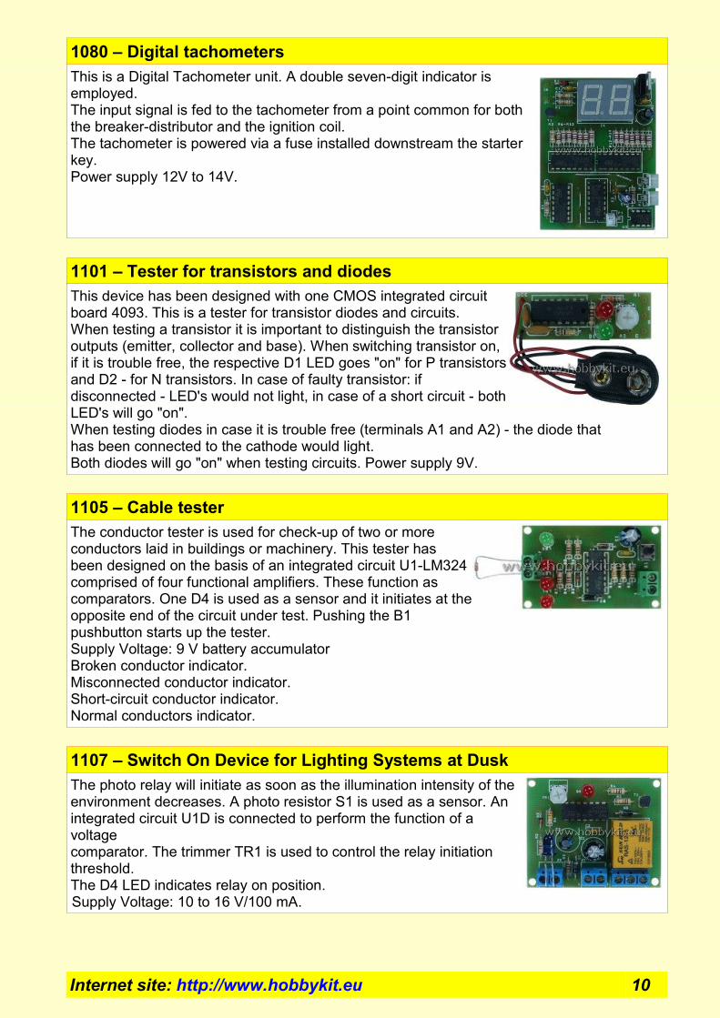
1080 – Digital tachometers
This is a Digital Tachometer unit. A double seven-digit indicator is employed. The input signal is fed to the tachometer from a point common for both the breaker-distributor and the ignition coil.The tachometer is powered via a fuse installed downstream the starter key.Power supply 12V to 14V.
1101 – Tester for transistors and diodes
This device has been designed with one CMOS integrated circuit board 4093. This is a tester for transistor diodes and circuits. When testing a transistor it is important to distinguish the transistor outputs (emitter, collector and base). When switching transistor on, if it is trouble free, the respective D1 LED goes "on" for P transistors and D2 - for N transistors. In case of faulty transistor: if disconnected - LED's would not light, in case of a short circuit - both LED's will go "on". When testing diodes in case it is trouble free (terminals A1 and A2) - the diode that has been connected to the cathode would light. Both diodes will go "on" when testing circuits. Power supply 9V.
1105 – Cable tester
The conductor tester is used for check-up of two or more conductors laid in buildings or machinery. This tester has been designed on the basis of an integrated circuit U1-LM324 comprised of four functional amplifiers. These function as comparators. One D4 is used as a sensor and it initiates at the opposite end of the circuit under test. Pushing the B1 pushbutton starts up the tester.Supply Voltage: 9 V battery accumulatorBroken conductor indicator.Misconnected conductor indicator.Short-circuit conductor indicator.Normal conductors indicator.
1107 – Switch On Device for Lighting Systems at Dusk
The photo relay will initiate as soon as the illumination intensity of the environment decreases. A photo resistor S1 is used as a sensor. An integrated circuit U1D is connected to perform the function of a voltage comparator. The trimmer TR1 is used to control the relay initiation threshold. The D4 LED indicates relay on position.Supply Voltage: 10 to 16 V/100 mA.
Internet site: http://www.hobbykit.eu 10

1109 – Thermostat (5 – 30*C)
The thermal relay is used for temperature control in the range 5 to 30*C. C via heating elements initiated by a mechanical relay P1. This thermostat has been designed based on an integrated circuit LM324, consisting of four functional amplifiers built as one unit.Supply Voltage: 10 to 16 V/100 mATemperature Range: 5 to 30*C.
1111 – Liquid Level Controller (Level Meter)
The Level Controller is used to indicate the level of liquids contained in tanks and respectively, to initiate a high level relay and to trip in case of low-level values. When high level probes are submerged in liquid, a high-level indicator D7 goes on and this will result in initiation of P1 relay and LED D10 will light. Identically, intermediate level probes are also submerged in the liquid. The relay P1 will be on even when high-level probes are not submerged in the liquid. When the liquid level becomes lower than the intermediate level probes, a low-level LED D9 will light. This will result in tripping of relay P1.Supply Voltage: 10 to 16 V/100 mA.Low-level indicator. Intermediate-level indicator.High-level indicator.Relay-On indicator.
1201 – Termoregulated /max 1000W/
The temperature controller has been designed with one integrated circuit board 723. It is powered direct with 220V. A common type of thermal resistor RV1 is used as thermal sensor. Its resistance increases with temperatures rise. Two LED's D6 and D7 have been used as indicators. D6 indicates "on" position of thermal controller, while D7 - consumer "on" (in case that the relay has been activated). This relay can be used to control a consumer with power 1000W maximum. Power supply 220V.
Internet site: http://www.hobbykit.eu 11

1301 – Car alarm system 2 /PIC12C508, PIC12C509/
The alarm system has been designed on the basis of a micro controller PIC12C508 made by the Microchip Company. It has the following functions: Activation time (time required for exit after activation) – 15 seconds. The two zones (zone 1 - push buttons for doors and zone 2 - shock sensor) are not active at that moment. Only the front and boot lid push buttons are active. Time for tripping (the time period from door opening till tripping or activation of alarm signal) - 8 seconds. Time for alarm signal - 45 seconds. Power supply 12V to 14V.
1305 – Home alarm system /PIC12C508, PIC12C509/
This alarm system has been designed on the basis of micro controller PIC12C508 made by the Microchip Company. It has the following functions: Activation time (the time period after switch on) - 45 seconds. The two zones (zone 1 - door sensor and zone 2 -window sensor or volume sensor) are not active at that moment. Panic push button is active only. Activation time (the time from door opening till tripping or activation of alarm signal) - 20 seconds. Alarm signal time - 165 seconds. Power supply 12V to 14V.
1310 – Melody door bell - 4 melody /PIC12C509/
The ringer has been designed on the basis of a micro controller made by the Microchip Company. The tunes recorded in the memory of the micro controller are played in a sequence for each pressing of the push button. Power supply 3V to 5V.
1325 – Timing relays 0-99 min /PIC12C508, PIC12C509/
The time relay has been designed on the basis of a micro controller PIC12C508 made by the Microchip Company. One dual seven-segment indicator is employed for indication, showing the remaining time. Two push buttons are used for setting relay operation time (this relay has a normal open and a normal close contact) B1 for the first and b2 for the second element of the seven-segment indicator. Power supply 9V to 14V.
Internet site: http://www.hobbykit.eu 12

1400 – FM Radio receiver /88 – 108 MHz/
The radio receiver has been designed with two integrated circuits TDA7000, being a FM receiver and a LM386 being a low-frequency amplifier. The potentiometer PI is used to control the sound loudness, P2 serves to select a broadcasting radio station. The coil LI serves to adjust the receiver within the range 88 to 108 MHz (via extension and contraction). Power supply 8 to 12V.
Internet site: http://www.hobbykit.eu 13

Modules
1500 – Audio amplifier 2x10W
Audio amplifier realized by one IC TDA 2005 (TDA 2004). Output power - 2x10W, Ucc=14,4V RL=2 OM.Power supply - 8 to 18VFrequency band - 22 to 22000 Hz
1501 – Audio amplifier 20W
Audio amplifier realized by two ICs TDA 2003 in bridge connection. Output power - 20W, Ucc=14,4V RL=2 OM.Power supply - 8 to 18VMax. Current – 3A.Frequency band - 22 to 22000 Hz.
1502 – FM radio microphone (88-108 MHz)
This circuit is a miniature transmitter in FM range of 88 to 108 MHz. Power supply 9V.
1503 – Stereo VU-meter /12 LEDs/
This device is realized with a IC КА2281, that controls2x5 LEDs (of type 'scale').Power supply 9 to 12V.
1504 – Audio amplifier 2x20W
Audio amplifier realized by one IC TA 8210.Output power - 2x20W, Ucc=14,4V RL=4 ОМPower supply - 8 to 18VFrequency band - 20 to 22000 Hz
1505 – Regulated power supply 1,2 to 30V / 1A
This device is realized with one IC LM317T. Input voltage - 35VOutput voltage - 1,2 to 30VI max - 1А
Internet site: http://www.hobbykit.eu 14

1506 – Power supply 12V/3A and battery charger
The power supply unit has been designed with two IC LM317T. The trimmer potentiometer is used to control the output voltage (10 to 14V). In case of use of a battery, the output voltage is set to 13,6V to allow for re-charge of the battery. In case that the input voltage is cut, the battery is on. The power supply unit is suitable for powering of alarm systems and other devices that must be in continuous operation even in case of power mains failure. This device can operate also without a battery. Input voltage - 22V. Output voltage - 10 to 14V Output current - 3А
1510– FM Radio receiver /88 – 108 MHz/
The radio receiver has been designed with two integrated circuits TDA7000, being a FM receiver and a LM386 being a low-frequency amplifier. The potentiometer PI is used to control the sound loudness, P2 serves to select a broadcasting radio station. The coil LI serves to adjust the receiver within the range 88 to 108 MHz (via extension and contraction). Power supply 8 to 12V.
1520 – VU-meter /12 LEDs/
This is a single function indicator designed with discrete elements. Input level is standard - 0,750V. Supply voltage - 9 to 15V.
1521 – Stereo VU-meter /12 LEDs/
This device is realized with 2 specialized IC KA2284 /AN6884/. IC control 5 LEDs (5 dot bar type). Two entrances - for left and right channels.Built-in amplifier input. Trimmer to adjust the level. Logarithmic indicator-10dB,-5dB, 0dB, 3dB, 6dB. Constant output current of 15mA. Supply voltage from 6 to 15V DC.
1525 – Colour music device /3x3 light-emitting diodes - LED's/
The device employs transistors. Tl and T2 - microphone preamplifier, PI serves to control the microphone response. The filters employ R6 and C5 - low frequencies: C7, R7 and C8 - middle range frequencies and C10 - high frequencies. Power supply 9 to 18V.
Internet site: http://www.hobbykit.eu 15
1535 – Microphone preamplifier
This device is a transistor preamplifier with an electret microphone, connected at the input. Power supply 3 to 12V.
1540 – Mini PIC programmer
The programmer has been designed to program the PIC micro controllers of the type: PIC16C55x, PIC16C61, PIC16C62x, PIC16C71, PIC16C71x, PIC16C8x, PIC16F8x, PIC12C508, PIC12C509, PIC12C67 and EEPROM 24Cxx of the Microchip company. It needs no additional power supply unit. The device is to be connected to the COM2 of the computer.
1551 – Car alarm system 2 /PIC12C508, PIC12C509/
The alarm system has been designed on the basis of a micro controller PIC12C508 made by the Microchip Company. It has the following functions: Activation time (time required for exit after activation) - 15 seconds. The two zones (zone 1 - push buttons for doors and zone 2 - shock sensor) are not active at that moment. Only the front and boot lid push buttons are active. Time for tripping (the time period from door opening till tripping or activation of alarm signal) - 8 seconds. Time for alarm signal - 45 seconds. Power supply 12V to 14V.
1552– Home alarm system /PIC12C508, PIC12C509/
This alarm system has been designed on the basis of micro controller PIC12C508 made by the Microchip Company. It has the following functions: Activation time (the time period after switch on) - 45 seconds. The two zones (zone 1 - door sensor and zone 2 -window sensor or volume sensor) are not active at that moment. Panic push button is active only. Activation time (the time from door opening till tripping or activation of alarm signal) - 20 seconds. Alarm signal time - 165 seconds. Power supply 12V to 14V.
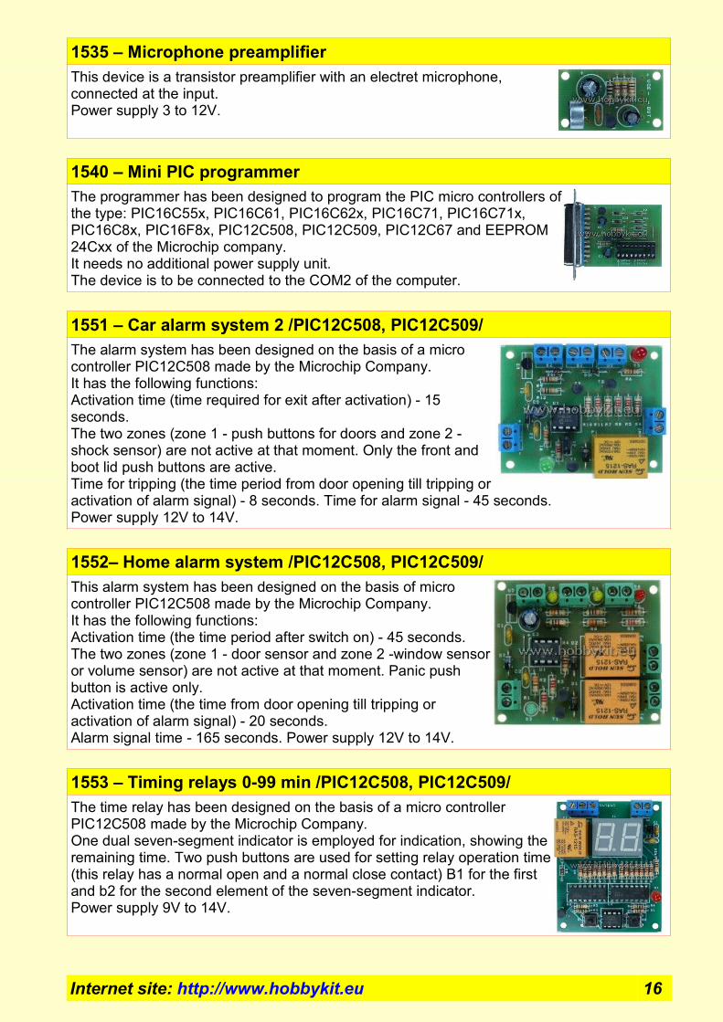
1553 – Timing relays 0-99 min /PIC12C508, PIC12C509/
The time relay has been designed on the basis of a micro controller PIC12C508 made by the Microchip Company. One dual seven-segment indicator is employed for indication, showing the remaining time. Two push buttons are used for setting relay operation time (this relay has a normal open and a normal close contact) B1 for the first and b2 for the second element of the seven-segment indicator. Power supply 9V to 14V.
Internet site: http://www.hobbykit.eu 16

1554 – Digital tachometers
This is a Digital Tachometer unit. A double seven-digit indicator is employed. The input signal is fed to the tachometer from a point common for both the breaker-distributor and the ignition coil.The tachometer is powered via a fuse installed downstream the starter key.Power supply 12V to 14V.
1560 – Audio amplifier 100W /TDA 7294/
Low-frequency amplifier "AB" class has been designed with an integrated circuit TDA7294. Amplifier Features: Output power (sinusoid) 70W (0,5% distortion) in case of power supply: Uсс=±35V for Rт=8 ОM, Uсс=±27 for Rт=4 ОM; Output power (musical) 100 W (10% distortion) in case of power supply: Uсс=±38V for Rт=8 ОM, Uсс=±29 for Rт=4 ОM; Input signal - 0,75V Quiescent current: 30mA; "MUTE" mode (transition to mode "input signal off'); Supply voltage: ±10 to ±40V;Peak moment output current: 10А;
1561 – Hi – Fi Audio amplifier 100W
Audio amplifier designed with one IC NE 5534 and two 2N3055 /KD503/.Parameters: Output power - 100W / ±40V Input level - 0,75V Linear distortion range - 0,003% Frequency band - 20 to 20000 Hz ±1dB Power supply ±20 to ±40V Max. Current - 2А
1566 – Thermostat (5 – 30*C)
The thermal relay is used for temperature control in the range 5 to 30*C. C via heating elements initiated by a mechanical relay P1. This thermostat has been designed based on an integrated circuit LM324, consisting of four functional amplifiers built as one unit.Supply Voltage: 10 to 16 V/100 mATemperature Range: 5 to 30*C
Internet site: http://www.hobbykit.eu 17

1570 – Audio amplifier 1W
Audio amplifier realized by one IC TA 7368P. Output power – 1,1W, Ucc=14V RL=4 OM.Power supply - 6 to 14VFrequency band - 22 to 22000 Hz
1572 – Liquid Level Controller (Level Meter)
The Level Controller is used to indicate the level of liquids contained in tanks and respectively, to initiate a high level relay and to trip in case of low-level values. When high level probes are submerged in liquid, a high-level indicator D7 goes on and this will result in initiation of P1 relay and LED D10 will light. Identically, intermediate level probes are also submerged in the liquid. The relay P1 will be on even when high-level probes are not submerged in the liquid. When the liquid level becomes lower than the intermediate level probes, a low-level LED D9 will light. This will result in tripping of relay P1.Supply Voltage: 10 to 16 V/100 mALow-level indicator. Intermediate-level indicator.High-level indicator.Relay-On indicator.
1573 – Switch On Device for Lighting Systems at Dusk
The photo relay will initiate as soon as the illumination intensity of the environment decreases. A photo resistor S1 is used as a sensor. An integrated circuit U1D is connected to perform the function of a voltage comparator. The trimmer TR1 is used to control the relay initiation threshold. The D4 LED indicates relay on position.Supply Voltage: 10 to 16 V/100 mA.
1575 – Cable tester
The conductor tester is used for check-up of two or more conductors laid in buildings or machinery. This tester has been designed on the basis of an integrated circuit U1-LM324 comprised of four functional amplifiers. These function as comparators. One D4 is used as a sensor and it initiates at the opposite end of the circuit under test. Pushing the B1 pushbutton starts up the tester.Supply Voltage: 9 V battery accumulatorBroken conductor indicator.Misconnected conductor indicator.Short-circuit conductor indicator.Normal conductors indicator.
Internet site: http://www.hobbykit.eu 18

1580 – Time Relay (0 to 160 seconds)
The time relay has been designed based on a timer 555-U1 connected to the anticipating multi vibrator circuit. The relay will be reset using the B2 pushbutton and will remain in anticipating mode. Pushing B 1 once will initiate the relay for a defined period. The time setting of the relay is determined by the C4 capacitor and the Tr1 trimmer and can be adjusted in the range 0 to 160 seconds. The LD LED indicates On/Off position of the relay.Supply Voltage: 10 to 16 V /100 mA.Pushbutton ONEmergency stop button.
1585 – Alarm system with code
The alarm system has been designed to safeguard premises. It is based on a PIC16F628 Microchip micro controller.The system has the following functions:Three zones: Zone 1 - lag (door). Zone 2 - instant (volume sensor/sensors) and TMP Zone - 24-hour security for the cables and the system itself.Two 4-digit codes: User code - for ON/OFF position of the alarm system and an engineering code - for programming purposes.Re-setting of input, output and alarm signal time, re-setting of the user and engineering codes.Input time: 5,10 and 20 seconds.Output time: 10,20 and 30 seconds.Alarm signal time: 30,60 and 120 seconds.Mode (Ringer) - When zone one is activated (the door opens) - a sound signal will be provided.Sound and light indication.Keyboard with 12 buttons.
1587 – Кодова брава
The code door has been designed to safeguard premises. It is based on a PIC16F628 Microchip micro controller. The system has the following functions: 2 zones: Zone 1 - door sensor and ТМР zone - 24-hour security for the cables and the system itself. Button - open indoors. Two 4-digit codes: User code - for Open/Close ( ) door and an engineering code - for programming purposes. Re-setting of output time, re-setting of the user and engineering codes. Sound and light indication. Keyboard with 12 buttons.
Internet site: http://www.hobbykit.eu 19

9905 – LED Beacon
8 Channel round chaser / beacon.PIC microcontoller.16 programs + demo program.Demo program - show all 16 program.Button - choice program.Power supply - 8 to 14V.Memory - remember last selected program.Overall dimensions PCB diameter 34,5mm (1.36").Available in following colors: White, Red, Yellow, Green, Blue, Multi colour.
9910 – LED Chaser
8 Канален преследвач.PIC microcontoller.12 programs + demo program (for multi color - 11 programs + demo program).Demo program - show all program.Speed control - trimmer-potentiometer.Button - choice program.Power supply - 8 to 14V.Memory - remember last selected program.Overall dimensions PCB 74mm x 36,5mm.Available in following colors: White, Red, Yellow, Green, Blue, Multi colour (2 Yellow, 2 Red, 2 Blue и 2 Green LED's).
9915 – LED Strobe
PIC microcontoller.4 jumper - choice regime.9 LED's for PCB.Possible inclusion of more LEDs.The strobe interval can be configured using 4 jumpers for 0.5, 1, 2 or 3 seconds, strobe on time of 30mS or 100mS and single or double strobe pulse.Power supply - 8 to 14V.Overall dimensions PCB 57mm x 28mm.Overall dimensions PCB for LEDs 44mm x 28mm.Available in following colors: White, Red, Yellow, Green, Blue.
Internet site: http://www.hobbykit.eu 20

9918 – LED Strobe 12 LED
12 LED Strobe. 12x 5mm LEDs . Jumper - choice mode (fast and normal). Power supply DC - 8 to 14V.Available in following colors: White, Red, Yellow, Green, Blue.
9930 – Knight Rider Scanner 16 LED's Chaser
16 LEDs chaser. Effects - Knight Rider Scanner, GhostBusters, Proton Pack Power, Battlestar Galactica CYLON EYE and other.PIC microcontoller - PIC16F684. 11 programs. Speed control - trimmer-potentiometer. Button - choice program. 16x 5mm LEDs. Power supply DC - 8 to 14V (You can use the car battery). Memory - remember last selected program. Available in following colors: White, Red, Yellow, Green, Blue.
9940 – Audio VU meter 16 LED - 4 programs
PIC microcontoller.Input signal - Electret Microphone (included).4 programs.Gain control - Trimmer.Button - choice program.Power supply - 8 to 14V.Memory - remember last selected program.Overall dimensions PCB 135mm x 51mm.Available in following colors: White, Red, Yellow, Green, Blue.
9980 – Programmable controller for lighting effects 1 to 10 channels
The controller is designed for management of LEDs or LED modules (advertising signs, decoration of rooms and buildings, etc.). The controller can manage from 1 to 10 channels. Up to 29 different effects depending on the chosen number of channels (pre-programmed in the controller). Each effect can be repeated from 1 to 10 times independently of one another. Adjust speed for effects.Select a channel to be used – from 1 to 10 channels.Choice of effects that will appear – depending on the selected numbers of channels.Choice of repetition for one effect – from 1 to 10 times for each effect.Power DC 8 to 18V. Maximum total current – 10A (1A per channel).Two programmable buttons SB1 and SB2. One button RESET SB3 – restore factory settings. Trimmer-potentiometer R1 for regulating the speed of the effects.Possibility for upgrade of effects saved – by changing the eeprom 24Cxxx.Overall dimensions PCB 134mm x 68mm.
Internet site: http://www.hobbykit.eu 21

9982 – LED Controller 2 channel
2 Channel LED Controller. PIC microcontoller. 5 programs + demo program. Demo program - show all 5 program. Button - choice program. Pressing - next program. Hold for 4 secound - demo (program 0). You select one of 5 programs, or all 5 programs running at 5 times. Speed control – trimmer-potentiometer. Power supply DC - 8 to 18V. LED module ready for DC 12V. Current depends on the number of used LED module (LEDs). Max 5A. Memory - remember last selected program.
9983 – LED Controller 3 channel
3 Channel LED Controller. PIC microcontoller.16 programs + demo program. Demo program - show all 16 program. Button - choice program. Pressing - next program. Hold for 4 secound - demo (program 0). You select one of 16 programs, or all 16 programs running at 5 times. Speed control – trimmer-potentiometer. Power supply DC - 8 to 18V. LED module ready for DC 12V. Current depends on the number of used LED module (LEDs). Max 5A. Memory - remember last selected program.
9984 – LED Controller 4 channel
4 Channel LED Controller. PIC microcontoller.17 programs + demo program. Demo program - show all 17 program. Button - choice program. Pressing - next program. Hold for 4 secound - demo (program 0). You select one of 17 programs, or all 17 programs running at 5 times. Speed control – trimmer-potentiometer. Power supply DC - 8 to 18V. LED module ready for DC 12V. Current depends on the number of used LED module (LEDs). Max 5A. Memory - remember last selected program.
9990 – LED dimmer
Adjustable controller for LED, lamp and motor. PIC microcontoller. Adjustable Brightness / speed - potentiometer. Button for smooth ON and OFF. Power supply DC - 8 to 24V. LED module ready for DC 12V. Current - 2A without heatsink.
Internet site: http://www.hobbykit.eu 22

Printed circuit boards
Engineering design, manufacture and delivery of printed circuit boards (PCB's):
Single-sided S PCB's.Double-sided D PCB's.Solder mask.White prints.Noble metal coatings.Scribing, milling and die-stamping.Sprayed- metal coating of holes.
Universal PCB's
Universal PCB's - single sided. Dimensions: 42х65 mm. Universal PCB's - single sided. Dimensions: 100х167 mm. Universal PCB's - double sided. Dimensions: 100х167 mm.Universal PCB's - double sided, SMD. Dimensions: 100х160 mm.
Internet site: http://www.hobbykit.eu 23

Universal boxes
Universal box 1
Dimension: 140mm x 130mm x 200mmm
Universal box 2
Dimension: 205mm x 130mm x 250mm
Universal box 3
Dimension: 200mm x 100mm x 265mm
Internet site: http://www.hobbykit.eu 24

Manufacturer
MIG – GG Corp.Office: Bulgaria Burgas Northern Industrial Zone
ks. "Slaveykov", str. "Janko Komitov" 18Warehouse "Iskra", floor 4GSM: +359 88 8809808GSM: +359 89 9984310
Kralev i sin Corp.Office: Bulgaria Plovdiv str. "N. Bozveli" 11a
GSM: +359 89 9984300
e-mail: [email protected]: [email protected]
e-mail: [email protected]
http://www.hobbykit.eu