HISTOGRAM FILTER FOR ATTITUDE DETERMINATION OF …HISTOGRAM FILTER FOR ATTITUDE DETERMINATION OF...
15
HISTOGRAM FILTER FOR ATTITUDE DETERMINATION OF SMALL ASTEROID LANDER M. Schlotterer, R. Findlay, T.-M. Ho, L. Witte, C. Ziach. German Aerospace Center, Institute of Space Systems Robert-Hooke-Str. 7, 28359 Bremen, Germany, [email protected] ABSTRACT The Mobile Asteroid Surface Scout (MASCOT) is a small landing package build by the German Aerospace Cen- ter (DLR) jointly with the French Space Agency (CNES). MASCOT will fly onboard the Japanese space probe Hayabusa-II, built by the Japan Aerospace Exploration Agency (JAXA) and is scheduled to be launched in late 2014 on a 5-year sample return mission to the Near-Earth Asteroid 1999 JU 3 . The lander is equipped with four science instruments which will take detailed close-up pictures and make a variety of in-situ measurements. MAS- COT has a cubic shape roughly 29 cm × 27.5 cm × 20 cm and weighs about 10 kg. An internal mechanism with an eccentric tappet can be used to reorient MASCOT if needed and relocate to a different site to increase its investigation area. After the arrival and a characterization of the asteroid, MASCOT will be dropped from the Hayabusa-II mothership and will land passively on the asteroid surface. Before starting science measurements MASCOT must lie on the correct side. The attitude determination system consists of 2 types of sensors: solar cell based sun sensors on each side of MASCOT as well as 5 optical proximity sensors (OPS). The latter consists of an LED and a photodiode which can detect the reflected LED light when MASCOT is in proximity to the surface. A histogram filter is used for attitude determination and multi sensor data fusion. It is a bayesian filter used to estimate states which can be divided in a finite number of possible values. This is useful for MASCOT since all that is needed is an estimation of the side on which it is lying. This paper focuses on the attitude determination system of MASCOT. It describes the attitude determination sensors and the details of the filter algorithm. It also presents simulation results for system verification, as well as planned Monte-Carlo simulation and Hardware-in-the-Loop tests. 1. INTRODUCTION For the navigation of spacecraft algorithms are needed to estimate states from the measurement of different sensors. One widely used class of algorithms are Kalman Filters, especially Extended Kalman Filters (EKF) and more and more also Unscented Kalman Filters (UKF) [4]. All of them have in common that they require Gaussian noise sources, a more or less linear system and an exact knowledge of the systems dynamics and measurement model. For robotic missions, especially exploration missions this is not always given: due to contact dynamics the system model is highly nonlinear and even not very well known in many cases. A common answer to this are Particle Filters or Gaussian Sum Filters with the drawback of a complex implementation, high computational load, big tuning effort and without guarantee of convergence in any case. For some cases also the not so well known Histogram Filter is a good choice. The Mobile Asteroid Surface Scout (MASCOT) is such a case. It will fly onboard the Japanese space probe Hayabusa-II to the Near-Earth Asteroid 1999 JU 3 and will be dropped after arrival to land passively on the asteroid surface. The task of its GNC system is to determine the side on which MASCOT is lying. The fact that these 6 possible sides are a discrete state of the system with a finite number of states makes the Histogram Filter a preferred choice. This paper starts with a description of the MASCOT mission and lander. An extra section is dedicated to the MASCOT GNC System, showing the system concept and architecture as well as the used sensors. The paper gives a short theoretical introduction in Bayesian Filters in general with a special focus on the Histogram Filter. It will also be shown how this type of estimation algorithm can be adapted for the MASCOT GNC System. The last section presents the test and verification methods to show that the proposed algorithm is suitable for the given requirements. For the software simulation also simulation results will be shown. 1
Transcript of HISTOGRAM FILTER FOR ATTITUDE DETERMINATION OF …HISTOGRAM FILTER FOR ATTITUDE DETERMINATION OF...

HISTOGRAM FILTER FOR ATTITUDE DETERMINATION OF SMALL ASTEROID LANDERM. Schlotterer, R. Findlay, T.-M. Ho, L. Witte, C. Ziach.German Aerospace Center, Institute of Space Systems
Robert-Hooke-Str. 7, 28359 Bremen, Germany, [email protected]
ABSTRACT
The Mobile Asteroid Surface Scout (MASCOT) is a small landing package build by the German Aerospace Cen-ter (DLR) jointly with the French Space Agency (CNES). MASCOT will fly onboard the Japanese space probeHayabusa-II, built by the Japan Aerospace Exploration Agency (JAXA) and is scheduled to be launched in late2014 on a 5-year sample return mission to the Near-Earth Asteroid 1999 JU3. The lander is equipped with fourscience instruments which will take detailed close-up pictures and make a variety of in-situ measurements. MAS-COT has a cubic shape roughly 29 cm×27.5 cm×20 cm and weighs about 10 kg. An internal mechanism withan eccentric tappet can be used to reorient MASCOT if needed and relocate to a different site to increase itsinvestigation area.
After the arrival and a characterization of the asteroid, MASCOT will be dropped from the Hayabusa-II mothershipand will land passively on the asteroid surface. Before starting science measurements MASCOT must lie on thecorrect side. The attitude determination system consists of 2 types of sensors: solar cell based sun sensors on eachside of MASCOT as well as 5 optical proximity sensors (OPS). The latter consists of an LED and a photodiodewhich can detect the reflected LED light when MASCOT is in proximity to the surface.
A histogram filter is used for attitude determination and multi sensor data fusion. It is a bayesian filter used toestimate states which can be divided in a finite number of possible values. This is useful for MASCOT since allthat is needed is an estimation of the side on which it is lying.
This paper focuses on the attitude determination system of MASCOT. It describes the attitude determination sensorsand the details of the filter algorithm. It also presents simulation results for system verification, as well as plannedMonte-Carlo simulation and Hardware-in-the-Loop tests.
1. INTRODUCTION
For the navigation of spacecraft algorithms are needed to estimate states from the measurement of differentsensors. One widely used class of algorithms are Kalman Filters, especially Extended Kalman Filters (EKF) andmore and more also Unscented Kalman Filters (UKF) [4]. All of them have in common that they require Gaussiannoise sources, a more or less linear system and an exact knowledge of the systems dynamics and measurementmodel. For robotic missions, especially exploration missions this is not always given: due to contact dynamics thesystem model is highly nonlinear and even not very well known in many cases. A common answer to this areParticle Filters or Gaussian Sum Filters with the drawback of a complex implementation, high computationalload, big tuning effort and without guarantee of convergence in any case. For some cases also the not so wellknown Histogram Filter is a good choice.
The Mobile Asteroid Surface Scout (MASCOT) is such a case. It will fly onboard the Japanese space probeHayabusa-II to the Near-Earth Asteroid 1999 JU3 and will be dropped after arrival to land passively on theasteroid surface. The task of its GNC system is to determine the side on which MASCOT is lying. The fact thatthese 6 possible sides are a discrete state of the system with a finite number of states makes the Histogram Filter apreferred choice.
This paper starts with a description of the MASCOT mission and lander. An extra section is dedicated to theMASCOT GNC System, showing the system concept and architecture as well as the used sensors. The papergives a short theoretical introduction in Bayesian Filters in general with a special focus on the Histogram Filter. Itwill also be shown how this type of estimation algorithm can be adapted for the MASCOT GNC System. The lastsection presents the test and verification methods to show that the proposed algorithm is suitable for the givenrequirements. For the software simulation also simulation results will be shown.
1

2. MASCOT
The exploration of minor bodies in the last few decades extended from flybys like Deep Space 1, orbiting (e.g.NEAR Shoemaker or Dawn) to sample return like Hayabusa. Future sample return missions, such as Hayabusa-2and OSIRIS-REx are currently planned.
The link between remote sensing, in-situ and sample return science can be achieved with multiple landings andin-situ measurements over a variety of asteroid terrains. An agile, lightweight, highly capable mobile platform isdesirable.
The German Aerospace Center (DLR) is currently developing in collaboration with CNES andISAS/JSPEC/JAXA a lander (MASCOT) in the class of a nanosatellite for the Hayabusa-2 mission. With a totalmass of ∼10 kg , MASCOT carries four scientific instruments: a camera (DLR), a hyperspectral microscopicimager (IAS), a magnetometer (TU Braunschweig) and a radiometer (DLR). The payload cumulatively weights∼3 kg. Once landed in 2018/19 on the C-type asteroid, (162173) 1999 JU3, the four instruments will study in-situits surface morphology and geological setting, its regolith structure, texture and composition, the thermal andmagnetic properties of the surface on 2-3 landing sites, enabled by MASCOT’s ability to hop across the asteroid.
A. LANDER CONCEPT
The MASCOT bus has a total volume of about 0.3 m×0.3 m×0.2 m. The structure is of lightweight carbonfiber sandwich framework supporting the payloads (P/L), a common electronic box, the passive thermalcontrol surfaces and the antennae for communication during surface operation. To upright itself into correctinstrument orientation and to perform relocation via hopping on the asteroid surface, MASCOT is equippedwith a mobility mechanism and a suite of GNC sensors. Control, housekeeping, autonomy, data handlingand local processing power are provided by a redundant on-board computer (OBC). Power is supplied byprimary battery via a redundant power subsystem (PCDU). The design goal is to operate up to two asteroiddays (one asteroid day is ∼7.5 h) on the surface. Communications to Earth is established via relay by themothership. Due to the short duration of surface operations (<16 h), the amount of direct telemetry to andcontrol commands from Earth is extremely limited, requiring almost complete autonomy of the lander.During cruise and the first phase of target reconnaissance, MASCOT is carried in a mechanical and electricalsupport structure (MESS) attached to the HY-2 spacecraft. Within this time MASCOT is mostly inactive;thermal control and power supply for in-cruise operations are provided by the mothership.
B. MISSION CONCEPT
The interplanetary cruise will take approximately 4 years, with MASCOT nominally off except forcommissioning and periodic monitoring and calibration activities.
Fig. 1: CAD model of MASCOT incl. PL and S/S
2

After arrival at (162173) 1999 JU3, Hayabusa-2 (HY-2) will first perform a global mapping in order tocharacterize the asteroid, and also to assist with landing site selection for it’s sample return touchdown andMASCOT deployment.
With the landing site selected (based on local geology and thermal constraints), MASCOT will be released tothe surface, either during a dedicated descent or during one of the sampling touchdown rehearsals. HY-2 willdescend to the separation altitude of 100 m at which point MASCOT will get ejected via a springmechanism. The lander will fall to the asteroid surface under the effects of the weak gravity field, beforetouch-down in an unknown orientation. The descent to the asteroid after ejection will take approximately20 min, with communications to Hayabusa-2 maintained throughout. If possible, MASCOT will also takecamera images of the asteroid during descent.
Once landed, the highest priority of MASCOT is to upright and perform the scientific measurements. Aftercompletion of the first science cycle, the lander will relocate and start the 2nd science cycle.
C. MASCOT GNC SYSTEM
The tasks of the MASCOT GNC system are the detection of the motion state of the lander as well as theestimation of the side on which MASCOT is lying when at rest. To fulfill these tasks the GNC systemconsists of two types of sensors distributed over the MASCOT body as well as onboard algorithms runningon the MASCOT onboard computer as part of the onboard software.
The algorithm to detect the motion state (free fall, in proximity, at rest) is a decision logic which in principalchecks if the sensor readings are not changing for a specific amount of time. The algorithm for theestimation of the side on which MASCOT is lying is explained in detail in section 3.
The sensors used in the MASCOT GNC system are Optical Proximity Sensors (OPS) and Photoelectric Cellsensors (PEC).
OPTICAL PROXIMITY SENSOR (OPS)
The OPS, designed and manufactured by cosine measurement systems, is a small sensor(32.6 mm×27 mm×21.6 mm) with a mass of about 28 g. It consists of an infrared LED and anappropriate photo-diode (see Fig. 3). The light omitted by the LED is reflected by any object in theField of View (FoV) of the sensor. Nearer objects reflect more light and light from objects further awaythan 12 cm can not detected any more. This gives the opportunity to detect objects in proximity in acertain direction. In addition the LED is on/off modulated by the OBC and the signal from thephoto-diode is correlated with this modulation. With this method one can distinguish between reflectedlight from the LED and background illumination e.g. from sunlight. Fig. 4 shows the output voltage ofthe OPS as function of the distance from the object.
Fig. 2: Sketch of Separation & surface operation concept
3

Fig. 3: Optical Proximity Sensor (OPS)
Fig. 4: OPS output voltage as function of distance
Five of these sensors are used on MASCOT, mounted on 5 different sides of the cuboid. Only theinstrument side is not equipped with such a sensor. This space is needed for the scientific instruments.As one can see in Fig. 4 the output voltage decreases again for distances smaller than 10 mm. Toprevent such small distances, the sensors are not mounted flat to the surface but shifted inside the bodyof MASCOT.
The sensors have been built by cosine Research B.V. [3].
PHOTOELECTRIC CELL SENSOR (PEC)
The PEC is a solar cell based sun sensor. It holds a space qualified triple junction solar cell (measuring20 mm×20 mm) on a 20.5 mm×45 mm PCB together with two 50 Ω resistors connected in parallel tothe solar cell (see Fig. 5). Due to Lambert’s cosine law the output voltage UPEC is proportional to thecosine of the angle φ between the sun vector vSun and the normal vector of the solar cell nPEC:
UPEC =U0 cosφ =U0vSun ·nPEC
|vSun||nPEC|. (1)
Six of these sensors are used on MASCOT, one on every side of the MASCOT body. This makes itpossible to measure the sun vector in body fixed frame in all possible directions.
The sensors have been built by ZARM Technik AG, Bremen [7].
For the OPS as well as the PEC windows have been cut out in the outer wall of MASCOT (see Fig. 6).
3. HISTOGRAM FILTER FOR ATTITUDE DETERMINATION
For MASCOT, the state that has to be determined is the side of the MASCOT cuboid on which the lander is lying.In other words the side which faces the soil. If MASCOT is tilted, e.g. because the terrain is not flat, the side
4

Fig. 5: Photoelectric Cell Sensor (PEC) glued to MASCOT structure
Fig. 6: MASCOT (bottom view) with separation mechanism and windows for GNC sensors
5

which faces the soil the most needs to be determined. Tilted and non-tilted orientations are combined to onediscrete state instance. So the state space is discrete and can be divided in a finite number of states. For thisapplication the number of states is Ns = 6. For this types of system a so-called histogram (or grid-based Bayesian)filter can be used.
A. BAYESIAN FILTERS
Given the time-discrete dynamics function of a system by
xk = fk(xk−1,vk−1) (2)
with f as a possibly nonlinear function of the state x and the process noise v. The measurement function isgiven by
zk = hk(xk,nk) (3)
with the possibly nonlinear function h of the state and of the measurement noise nk. The objective of anyestimation filter is to recursively estimate the state xk from all available measurements z1:k up to time k.
A Bayesian filter recursively calculates the probability density function (PDF) p(xk|z1:k). Assumed the initialPDF p(x0) is known, the PDF p(xk|z1:k) can be obtained in two stages: prediction and update.
If the PDF p(xk−1|z1:k−1) at time k−1 is available, the predicted PDF can be obtained using the systemdynamics (2):
p(xk|z1:k−1) =∫
p(xk|xk−1)p(xk−1|z1:k−1)dxk−1. (4)
The probabilistic model of the state evolution p(xk|xk−1) is defined by the system dynamics (2) and thestatistics of the process noise vk−1.
The measurement update of the PDF is given using Bayes’ rule
p(xk|z1:k) =p(zk|xk)p(xk|z1:k−1)
p(zk|z1:k−1)(5)
with the normalizing constant
p(zk|z1:k−1) =∫
p(zk|xk)p(xk|z1:k−1)dxk. (6)
The PDF p(zk|xk) depends on the measurement model (3) and the statistics of the measurement noise nk.
Equations (4) and (5) can be used to recursively compute the PDF p(xk|z1:k) at each time step. Of course thiscan not be done analytically in general. For certain assumptions solutions exist:
• Kalman Filter: The system is linear and the noise is Gaussian distributed.
• Histogram Filter/Grid-Based Filter: The state space is discrete and can be divided in a finite number ofstates.
Other filters approximate the optimal Bayesian solution, e.g. Extended Kalman Filter or ParticleFilters [1] [2].
B. HISTOGRAM FILTERS/GRID-BASED FILTERS
If the state space is discrete and consists of a finite number of states, the Histogram Filter (or Grid-BasedFilter) provides the optimal solution for the estimation of the PDF p(xk|z1:k) [1] [8]. Let the finite number of
6

states be Ns. For each state xik, i = 1, . . . ,Ns at time k, let the conditional probability be pi
k|k. Then the PDFscan be written using the Dirac function δ ():
p(xk−1|z1:k−1) =Ns
∑i=1
pik−1|k−1δ
(xk−1− xi
k−1)
(7)
p(xk|z1:k−1) =Ns
∑i=1
pik|k−1δ
(xk− xi
k)
(8)
p(xk|z1:k) =Ns
∑i=1
pik|kδ
(xk− xi
k). (9)
With this, the prediction and update equation can be written as
pik|k−1 =
Ns
∑j=1
p jk−1|k−1 p(xi
k|xjk−1) (10)
pik|k =
pik|k−1 p(zk|xi
k)
∑Nsj=1 p j
k|k−1 p(zk|xjk). (11)
If the transition probability p(xik|x
jk−1) does not depend on time t nor on any external input u, it can be
interpreted as elements of a constant transition matrix Pk|k−1. With this, the prediction equation (10) can bewritten as a linear matrix equation:
pk|k−1 = Pk|k−1 pk−1|k−1. (12)
This linear equation can be understood as a system model acting on the discrete probability distribution pinstead of the state vector x. Using the law of total probability and Bayes’ theorem one can also prove that
Ns
∑i=1
p(xik|x
jk−1) = 1. (13)
That means that the sum of all elements of one column of the matrix P is 1.
Looking at the update equation (11) one can see that the normalizing factor ∑Nsj=1 p j
k|k−1 p(zk|xjk) in the
denominator is the same for all possible state xik. That means that this factor doesn’t have to be computed
explicitly. Instead, it is also possible to scale the pik|k such that ∑i pi
k|k = 1.
If there are several measurements it is even easier to split the measurement vector z into several scalarmeasurements zl and define the conditional probability p(zl
k|xik) for each of them. In that case (11) has to be
applied sequentially.
If one wants to apply the Histogram Filter to a system two things have to be done:
• Define the transition matrix Pk|k−1 =[
p(xik|x
jk−1)
].
• Define the continuous PDF p(zlk|xi
k) for each measurement zl and each possible state xi.
C. HISTOGRAM FILTER FOR MASCOT GNC
As already stated at the beginning of the section the task of the MASCOT GNC system is to determine theside of the MASCOT cuboid on which it is lying. Due to this fact the number of possible states is Ns = 6.The probability vector p is defined as
p =
p(x = x1)...
p(x = x6)
=
p(MASCOT is lying on side 1)...
p(MASCOT is lying on side 6)
. (14)
7

PREDICTION
The first step to be done to apply the Histogram Filter to the MASCOT GNC system is to define theprobability transition matrix Pk|k−1. Each element of this matrix represents the probability to flip fromone side to another. The probability that MASCOT keeps lying on the same side as in the previous timestep is denoted t, while the probability of changing to an adjacent side will be called q. s is theprobability of switching to the opposite side. Due to (13) it holds that
t +4q+ s = 1. (15)
The complete probability transition matrix P can than be written as
Pk|k−1 =
t q s q q qq t q s q qs q t q q qq s q t q qq q q q t sq q q q s t
(16)
The numbering of the sides of MASCOT can be seen in Fig. The values of t, q and s depend on thedynamics (especially on the attitude rate) of MASCOT as well as on the sample time ∆t = tk− tk−1.Setting them to constant values is of course a very rough simplification of the reality. The real dynamicsof MASCOT while rolling and hopping over the asteroids surface depend on:
• Structural properties of MASCOT lander
• Unknown soil parameters of asteroid surface
• Unknown terrain geometry.
Even with known soil parameters and terrain geometry it is hard to simulate the contact dynamicsbetween the MASCOT body and the asteroid surface. Unknown soil parameters and terrain geometrymakes it impossible to find a realistic dynamic model which can be implemented onboard the lander.This is why the simplified dynamic model (16) will be used. For this model, the following assumptionshave been made:
• Transition probabilities t, q and s are the same for all sides of MASCOT.
• Transition probabilities don’t depend on attitude rate, i.e. they are constant over time.
For a short GNC sample time of 2 s the transition probabilities have been set according to the followingtable:
t q s0.89 0.028 0
Fig. 7: MASCOT side numbering
8

UPDATE
For the update, a PDF p(zl |xi) has to be defined for each measurement zl and each possible state xi.Please note that the update will be performed sequentially and such all the measurements zl are scalar.Also the state x is a scalar in our case. The PDF p(zl |xi) is specific for each measurement and eachpossible state and depends continuously on the measurement zl .
OPS update In the case of the Optical Proximity Sensor (OPS) there are 5 measurements and 6possible states. So the number of PDFs to be defined is 5×6 = 30. But there are only two types ofPDFs: If the sensor is mounted on the appropriate side of MASCOT, the contact-PDF pCO is used.Otherwise, the non-contact-PDF pNC is used. The PDF type used for each OPS and each side ofMASCOT is given in Table 1. It can also be seen that on side No. 4 (the instrument side) no OPS ismounted and so no PDF of type CO will be used.
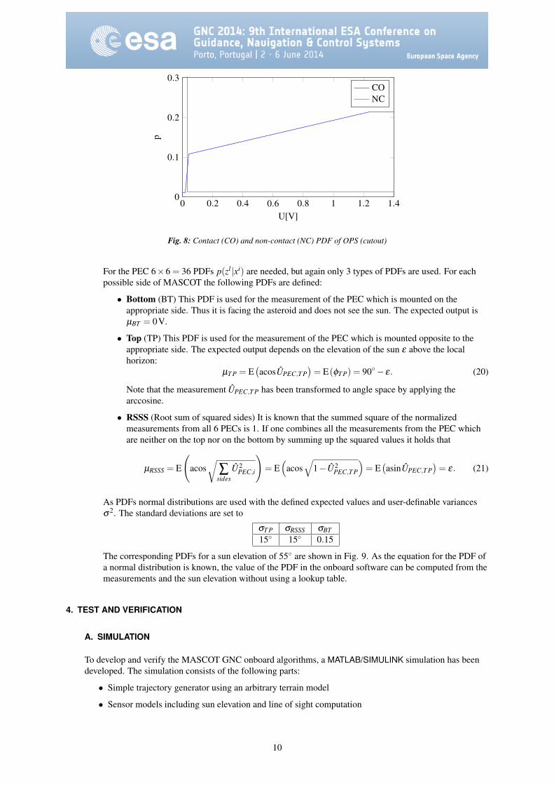
The PDF pCO(z) defines the probability density of a measurement z given that the appropriate side ofMASCOT is the bottom side and thus the appropriate OPS measures a contact to the soil. In this case itis very unlikely that the output of the sensor is almost zero. Other values are possible, depending onhow rough the surface of the asteroid is and how flat MASCOT is lying on it. But larger output values(smaller distance to ground) are more likely than smaller ones (larger distance to ground, see Fig. 4).Thus the probability increases up to a value of about 1.2 V. This is reflected in the PDF pCO(z) shown inFig. 8. The plot only shows a cutout of the complete PDF which stays constant for larger measurementvalues up to the maximum measurement value of 5 V. Note that, due to the law of total probability,∫
∞
−∞
p(zl |xi)dzl = 1 ∀zl ,xi. (17)
The PDF pNC(z) reflects the probability of a measurement z in the case that the side of MASCOT hasno contact to the soil and thus the appropriate OPS doesn’t see any object in proximity. The expectedoutput of the OPS is 0 V plus the noise of the sensor. So the probability density for values ≤ 20 mV islarge, while for values ≥ 30 mV it is almost zero. The PDF pNC(z) is also shown in Fig. 8. Note thatthere is no value z for which any of the two types of PDFs is set to 0. This is to reflect failure cases,which are unlikely but not impossible.
In the onboard software, the PDFs for the OPS are implemented as lookup tables with linearinterpolation between the data points.
PEC update From the characteristic curve of the PECs (eq. 1) one can show that
6
∑i=1
U2PEC,i =U2
0 . (18)
This makes it easy to normalize the PEC measurement by U0 which depends on the solar radiation:
UPEC,i =UPEC,i√
∑6i=1 U2
PEC,i
= cosφi. (19)
Table 1: Measurement PDFs for OPSOPS-No.
1 2 3 4 5
Side-No.
1 NC CO NC NC NC2 NC NC NC NC CO3 NC NC NC CO NC4 NC NC NC NC NC5 NC NC CO NC NC6 CO NC NC NC NC
9
0 0.2 0.4 0.6 0.8 1 1.2 1.40
0.1
0.2
0.3
U[V]
p
CONC
Fig. 8: Contact (CO) and non-contact (NC) PDF of OPS (cutout)
For the PEC 6×6 = 36 PDFs p(zl |xi) are needed, but again only 3 types of PDFs are used. For eachpossible side of MASCOT the following PDFs are defined:
• Bottom (BT) This PDF is used for the measurement of the PEC which is mounted on theappropriate side. Thus it is facing the asteroid and does not see the sun. The expected output isµBT = 0V.
• Top (TP) This PDF is used for the measurement of the PEC which is mounted opposite to theappropriate side. The expected output depends on the elevation of the sun ε above the localhorizon:
µT P = E(acosUPEC,T P
)= E(φT P) = 90− ε. (20)
Note that the measurement UPEC,T P has been transformed to angle space by applying thearccosine.
• RSSS (Root sum of squared sides) It is known that the summed square of the normalizedmeasurements from all 6 PECs is 1. If one combines all the measurements from the PEC whichare neither on the top nor on the bottom by summing up the squared values it holds that
µRSSS = E
(acos
√∑
sidesU2
PEC,i
)= E
(acos
√1−U2
PEC,T P
)= E
(asinUPEC,T P
)= ε. (21)
As PDFs normal distributions are used with the defined expected values and user-definable variancesσ2. The standard deviations are set to
σT P σRSSS σBT15 15 0.15
The corresponding PDFs for a sun elevation of 55 are shown in Fig. 9. As the equation for the PDF ofa normal distribution is known, the value of the PDF in the onboard software can be computed from themeasurements and the sun elevation without using a lookup table.
4. TEST AND VERIFICATION
A. SIMULATION
To develop and verify the MASCOT GNC onboard algorithms, a MATLAB/SIMULINK simulation has beendeveloped. The simulation consists of the following parts:
• Simple trajectory generator using an arbitrary terrain model
• Sensor models including sun elevation and line of sight computation
10

0 30 60 900
0.5
1
1.5
2
ε
acos√
∑sides U2PEC,i []
p RSS
S
RSSS
0 30 60 900
0.5
1
1.5
2
90− ε
acosUPEC,T P []
p TP
Top
0 0.2 0.4 0.6 0.8 10
1
2
3
UPEC,BT
p BT
Bottom
Fig. 9: Top, bottom and RSSS PDF of PEC for a sun elevation of 55
• Onboard algorithms
• Analysis tools
TRAJECTORY GENERATOR
A simple trajectory generator has been developed. The contact dynamics has been modeled as amass-spring-damper system and such it is not realistic. But due to the simple model the generator canbe processed very fast which gives us the possibility to run Monte-Carlo simulations. The parameters ofthe model has been adjusted to produce realistic velocities, attitude rates and times in which MASCOTcomes to rest. The trajectory generator also produces realistic resting positions. For that the altitude ofeach edge of MASCOT relative to the terrain model is computed. If the altitude is negative an upwardforce depending on relative altitude and velocity acts on the body of MASCOT. This force also causes atorque depending on the lever arm between the edge and the center of gravity. In addition, thegravitational force of the asteroid also acts on the body of MASCOT. These forces and torques are theinput for the well-known dynamic differential equations.
In addition a multibody simulation with a complex soil model has been built to produce more realistictrajectories. For this a dedicated multibody simulation tool has been used. Due to a large computationaleffort this simulation is not suitable for Monte-Carlo simulations. But the resulting trajectories can befed in the MASCOT GNC simulation to test the behavior of the GNC system for specific trajectories.
The terrain model used in the MASCOT GNC simulation is based on regular grid points at whicharbitrary elevations can be defined. This gives the possibility to define terrains with varying steepnessand roughness.
SENSOR MODELS
Using the trajectory (position, attitude) from the trajectory generator as well as the terrain model, theline of sight of each OPS can be computed (see Fig. 10). The terrain model is the same as the one usedbe the trajectory generator. Knowing the distance to voltage relation (see Fig. 4) the output of each OPScan be computed. The sensor model also includes noise and the possibility to simulate sensor failures.
SIMULATION RESULTS
The following figures show an example trajectory, the appropriate sensor output voltages as well as theresult of the attitude estimation. In Fig. 11 one can see the altitude of the MASCOT center, the rotationaround the x-axis α and the rotation around the y-axis β . The simulation starts at an altitude of 10 mwith random velocity, attitude and attitude rate. At about t = 160s MASCOT touches the asteroid
11

Fig. 10: MASCOT in resting position on rough terrain, lines of sight of OPS plotted
surface for the first time. This changes the attitude rate and MASCOT is rolling over the surface until itcomes to rest at about t = 750s. As the angle α is at about 180 at the end of the simulation, MASCOTcomes to rest lying on his back. In Fig. 12 the output voltages of the different sensors are shown.
The probabilities of the each surface is plotted in Fig. 13, depending only on OPS, only on PEC and thecombination of both. One can see that probabilities computed from OPS and from PEC estimate thesame ”‘side to soil”’ for the most times, but not always. This is because the OPS also detects a nearbysurface if this surface is left or right from MASCOT. On the other hand the PECs can not provide anon-ambiguous estimation if the sun elevation is low.
The last figure (Fig. 14) shows the result of the attitude estimation. On the left plot one can see the totalPDF including propagation. The center plot shows the estimated (most likely) side to soil together withthe true side to soil. For most times the estimated value coincides with the true value with a delay,which is caused by the propagation. the most important thing is that the estimated and the true value arethe same when MASCOT comes to rest. The estimated status of the lander has been plotted in the rightfigure.
B. MONTE-CARLO SIMULATIONS
It is planned to do Monte-Carlo simulations using the described software simulator. Including trajectoriesfrom the more realistic multibody simulation gives us the possibility to adapt parameters of attitudedetermination algorithm, especially the values for probability transition matrix P and for the measurementPDFs p(zl |xi). Varying the roughness of the terrain will show up to which roughness the GNC system will
0 200 400 600 800
−100
0
100
Time [s]
α[]
0 200 400 600 800−0.5
0
0.5
1
Time [s]
Alti
tude
ofM
ASC
OT
cent
er[m
]
0 200 400 600 800
−100
0
100
Time [s]
β[]
Fig. 11: Simulated sample trajectory
12

0 200 400 600 8000
0.5
1
1.5
Time [s]
UO
PS
0 200 400 600 8000
0.2
0.4
0.6
0.8
Time [s]
UP
EC
PEC1PEC2PEC3PEC4PEC5PEC6
Fig. 12: Output voltage of OPS and PEC
0 200 400 600 8000
0.2
0.4
0.6
0.8
1
Time [s]
p(z P
EC|x)
0 200 400 600 8000
0.2
0.4
0.6
0.8
1
Time [s]
p(z O
PS|
x)
0 200 400 600 8000
0.2
0.4
0.6
0.8
1
Time [s]
Com
bine
dPD
Fp(
z|x)
p(z|x1)
p(z|x2)
p(z|x3)
p(z|x4)
p(z|x5)
p(z|x6)
Fig. 13: Measurement PDF
0 200 400 600 8000
2
4
6
Time [s]
Est
imat
edsi
deto
soil Est.
True
0 200 400 600 8000
0.2
0.4
0.6
0.8
1
Time [s]
p k|k
0 200 400 600 8001
1.5
2
2.5
3
Time [s]
Est
imat
edst
atus
Fig. 14: Total PDF, estimated side to soil and status (1 = free fall, 2 = moving in proximity of asteroid, 3 = at rest)
13

work reliably and when it will start to estimate the wrong side to soil due to large nearby stones. This willalso influence the landing site selection at the asteroid.
C. SOFTWARE DEVELOPMENT AND VALIDATION FACILITY
A Software Development and Validation Facility (SDVF) based on the ESA SIMSAT simulationenvironment has been built for MASCOT. It contains simulation models for MASCOT subsystems as well asinterfaces to the real hardware. It also allows the usage of an emulator of the selected LEON chip instead ofthe real processor hardware.
In the context of the GNC subsystem, the SDVF allows Hardware-In-The-Loop (HIL) testing of the GNCsubsystem in the loop with the mobility subsystem, the MASCOT Autonomy Manager (MAM) andsimulated dynamics of MASCOT. Again, it is not possible to run the complete multibody simulation of theMASCOT dynamics on the SDVF. Such, the modeling approach is based on a finite number of precalculatedtrajectory parts. Each trajectory part starts and ends with MASCOT lying on one of the 6 possible sides,except the free fall trajectory parts which start with the separation from the mother ship. When being at rest,the next trajectory part is chosen depending on the attitude estimation of the GNC system, the decision of theautonomy manager and the actuation from the mobility system. This gives the possibility to simulate acomplete MASCOT mission starting from the separation from the mother ship until the battery is empty.
The GNC sensor models are the same as the ones for the pure software simulation of the GNC system (seesection 4.A). The GNC algorithms are part of the onboard software and as such run on the real processorhardware or on the emulator.
D. MASCOT GNC MOCKUP
A mockup of the MASCOT structure including the engineering models of the GNC sensors has been built totest the GNC subsystem in a realistic environment (see Fig. 15). It is planned to let the mockup drop on aterrain model with expected roughness and albedo, while the PEC will be stimulated by the Sun. To get arealistic free fall velocity and attitude rate while rolling on the asteroid, the mockup will be suspended by astring. During the movement, the data from the OPS as well as the PEC will be sampled by a USBmeasurement card and recorded for later use. This data can be fed into the MATLAB/SIMULINK simulation ofthe GNC algorithms to test the correct function of the attitude estimation algorithm. This test setup gives usthe possibility to fed the onboard algorithms with real sensor data. Of course, only a limited number of testtrajectories are possible.
Fig. 15: MASCOT Mockup including GNC sensors
14

5. CONCLUSION
The small asteroid lander MASCOT imposes specific requirements in its GNC system. A Histogram Filter hasbeen proposed as central algorithm for sensor data fusion and attitude estimation. The theory behind this filter hasbeen shown as well as how it can be adapted to the needs and the GNC sensors of MASCOT. A softwaresimulation has been built to verify the behavior of the filter and the fulfillment of the requirements and simulationresults have been shown.
In the next steps the GNC system has to proof its performance in Monte-Carlo simulations, varying initialconditions, sun elevation and terrain roughness. Furthermore Hardware-In-The-Loop tests will be conductedtogether with other subsystems of MASCOT.
REFERENCES
[1] Sanjeev Arulampalam, Simon Maskell, Neil Gordon, and Tim Clapp. A Tutorial on Particle Filters forOn-line Non-linear/Non-Gaussian Bayesian Tracking. IEEE Transactions on Signal Processing,50:174–188, 2001.
[2] Zhe Chen. Bayesian filtering: From Kalman filters to particle filters, and beyond. Statistics, 182(1):1–69,2003.
[3] S. Conticello, P. F. Manzillo, and M. Esposito. MASCOT GNC sensor system, Detailed design. Designreport CR-MGNC2-TN03, cosine Research B.V., March 2014. Internal document.
[4] J. Cote, A. Kron, J. de Lafontaine, J. Naudet, and S. Santandrea. PROBA-2 Attitude and Orbit ControlSystem: In-Flight Results of AOCS Flight Experiments. In 8th International ESA Conference on Guidance,Navigation & Control Systems. European Space Agency, 2011.
[5] Zhuohua Duan, Zixing Cai, and Jinxia Yu. Adaptive Particle Filter for Unknown Fault Detection ofWheeled Mobile Robots. In Intelligent Robots and Systems, 2006 IEEE/RSJ International Conference on,pages 1312–1315, Oct 2006.
[6] Josef Reill, Hans-Jurgen Sedlmayr, Sebastian Kuß, Philipp Neugebauer, Maximilian Maier, AndreasGibbesch, Bernd Schafer, and Alin Albu-Schaeffer. Development of a Mobility Drive Unit for Low GravityPlanetary Body Exploration. In ASTRA - 12th ESA Symposium on Advanced Space Technologies forRobotics and Automation, 2013.
[7] M. Rossol and A. Schotten. DLR Solar Cell Systems, Angle Dependant Solar Cell Measurement. Testreport DLR-TR-ZAR-SCS-01, ZARM Technik AG, September 2013. Internal document.
[8] Sebastian Thrun, Wolfram Burgard, and Dieter Fox. Probabilistic Robotics. Intelligent robotics andautonomous agents series. The MIT Press, 2005.
[9] L. Witte, J. Biele, A. Braukhane, Florian Herrmann, T.-M. Ho, C. Krause, Sebastian Kuß, C. Lange,M. Schlotterer, S. Ulamec, and S. Wagenbach. The Mobile Asteroid Surface Scout (MASCOT) - System &Mission Engineering and Surface Operations Concept. In Global Space Exploration Conference - GLEX,April 2012.
[10] C. Ziach, J.-P. Bibring, J. Biele, M. Deleuze, R. Findlay, T.-M. Ho, R. Jaumann, C. Lange, T. Okada,S. Ulamec, L. Witte, and H. Yano. The final development stages of MASCOT, a small asteroid lander toaccompany Hayabusa-II. In 64th International Astronautical Congress, September 2013.
15