Hinged Steel Belts Conveyors
10
Transcript of Hinged Steel Belts Conveyors


10
Hinged Steel Belts Conveyors
Hinged Steel Belt Comparison Chart
DRIVE IDLER FRAME FRAME DRIVER DRIVER SHAFT. IDLER IDLER SHAFT STANDARD STD.
MODEL DESCRIPTION GAUGE DEPTH SIZE TYPE DIA. SIZE TYPE DIA. CARRIER DRIVE OTHER
715 Light duty – 1-1/2" 14 4.125" 10 tooth 4.854 pd 1.1875" 1.375" OD Hub .75" 14ga aprons, 5/8" cleats Top Frame tapers from 4.125" @ infeed topitch chip conveyor on 12" centers 6-5/8" @ discharge
720 Medium duty chip conveyor 12 8.5" 6 tooth 5" pd 1.6875" 6 tooth 5" pd 1.1875" 12ga aprons, 1-3/8" cleats Top 720 – Heavy shaft M721723 Liquid tight M720 on 12-1/2" centers 723 – Heavy shaft, liquid tight M721
721 Standard duty scrap conveyor 12 8.5" 6 tooth 5" pd 1.4375" 6 tooth 5" pd 1.1875" 12ga aprons, 1-3/8" cleats Top Entire frame is 8-1/2" deep –724 Liquid tight M721 on 12-1/2" centers Flat top cleats are 1-1/8" high
722 Light duty chip conveyor 12 6.625" 5 tooth 4.25" pd 1.1875" 5 tooth 4.25" 1.1875" 12ga aprons, 7/8" cleats Top Entire frame is 6-5/8" deep – 726 Liquid tight M722 on 12-1/2" centers Flat top cleats are 5/8" high
725 Low profile infeed chip conveyor 12 5.375" 5 tooth 4.25 pd 1.1875" 1.75" OD Hub .75" 12ga aprons, 7/8" cleats Top Frame tapers from 5-3/8" to 6-5/8" – on 12-1/2" centers Flat top cleats are 5/8" high
727 Tapered infeed cold header conveyor 12 6.625" 5 tooth 4.25 pd 1.1875" 5 tooth 4.25" 1.1875" 12ga aprons, 5/8" cleats Top Frame tapers from 6-5/8" to 4-1/8" on 12-1/2" centers back to 6-5/8"
751 4" pitch HSB 10 15.25" 6 tooth 8" pd 1.9375" 6 tooth 8" pd 1.6875" 7ga aprons, 2-3/8" cleats Top M750 Takeup at Infeed750 Hvy drive shaft M751 10 15.25" 6 tooth 8" pd 2.9375" 6 tooth 8" pd 1.9375" on 24" centers M751 Takeup at Drive
760 6" pitch hinged steel belt Channel 23.25" 6 tooth 12" pd 3.4375" 6 tooth 12" pd 2.9375" 1/4" aprons, 4" cleats on Top Heavy duty hinged steel belt applications48" centers
Hinged Steel Belt Conveyors – Chip and Scrap Hinged Steel Belt Conveyors — Hinged Steel Belts are designed to carry hot & oily metal parts or scrap.When determining which hinged steel belt model fits your application, pay special attention to the unit’s frame depth and cleat height. A deeper frame adds the strength needed for longerruns and heavier loads. Deeper frames also provide the room for taller cleats. A taller cleat will move more product than a shorter one. A taller cleat may also be required for steeperinclines (For example, a 1-1/2" high cleat will carry more load up a 60 degree incline than a 5/8" high cleat.) Other unit’s lower profile frames are designed to fit into tight spaces.
Model 715 Model 722 & 726
Model 721 & 724
– Light duty, compact chip conveyor. – Light duty chip conveyor. – Standard duty chip conveyor.
Model 725
Model 751& 750
– Low profile infeedchip conveyor.
Model 727– Tapered infeed cold
header conveyor.
– Heavy duty chip &scrap conveyor.
Model 760
– Heavy duty scrapand chip conveyor.

Hinged Steel Belt Summary
Model 715Application Summary– Very low profile
– Very small and lightweight applications
Model 725Application Summary– Low profile
– Tight fit lightweight applications
Model 722 & Model 726Application Summary– Tight fit applications
– Small scrap conveyor(scrap less than 1/4" x 1/4" conveyor)
Model 721 & Model 724Application Summary– The industry’s most economical and dependable
scrap conveyor
Model 751Application Summary– Heavier scrap with high volumes
Model 760Application Summary– Heavy scrap and high volumes
Model 727Application Summary– Cold header conveyor
– Designed to fit into an existing machine
23-1/4"
15-1/4"
6-5/8"
4-1/4"
11

Hinged Steel Belt Conveyors are used to convey virtually any type of metal scrap. These rugged, heavy-duty conveyors are designed for long-term, low-maintenance operations in industrial, scrap, steel chip and fastener applications. They are ideally suited for carrying hot, oily partsfrom punch presses, forging machines, etc., to drums or hoppers. Various apron, sidewing, siderail and frame designs are available.
• The industry’s most economical and dependable hinged steel belt
• Designed for almost any industrial application
• Provides SteelTrak™ features when space is limited — 6-5/8" frame vs. 8-1/2"
• Designed for light to medium industrial applications
• Provides SteelTrak™ features when infeed space is very limited — 5-3/8" infeed
• Designed to fit under existing machines
•“Tapered” frame depth (6-5/8" to 4-1/8" to6-5/8") is designed to fit inside or underan existing machine
• Designed for medium to heavy industrial applications
• Designed for heavy industrial applications• Access panels full length are standard
STANDARD CLEATSSTEELTRAK™ PITCH CONVENTIONAL FLAT TOP FRAME FRAME SIDEWING STANDARDMODEL (PLATE SIZE) BELT BELT DEPTH GAUGE HEIGHT DRIVE @ 30 FPMModel 715 1-1/2" 5/8" high N/A Infeed 4-1/8" 10 3/4" 1/2 HP, 3 phase
on 12" centers Disharge 6-5/8"
Model 721 2-1/2" 1-1/2" high 1-1/8" high 8-1/2" 12 1-1/2" 1/2 HP, 3 phaseon 12-1/2" centers on 12-1/2" centers
Model 722 2-1/2" 1" high 5/8" high 6-5/8" 12 1" 1/2 HP, 3 phaseon 12-1/2" centers on 12-1/2" centers
Model 725 2-1/2" 1" high 5/8" high Infeed 5-3/8" 12 1" 1/2 HP, 3 Phaseon 12-1/2" centers on 12-1/2" centers Discharge 6-5/8"
Model 727 2-1/2" 1" high 5/8" high Tapered infeed 12 1" 1/2 HP, 3 Phaseon 12-1/2" centers on 12-1/2" centers 6-5/8" - 4-1/8"
Discharge 6-5/8"
Model 751 4" 10GA 3" high 7 GA 2-3/8" high 15-1/4" 10 3" 1/2 HP, 3 Phaseon 24" centers on 24" centers
Model 760 6" 4" high N/A 21-3/4" Struc. 4" 3 HP, 3 phaseon 48" centers Steel
SteelTrak™ Model 722 SteelTrak™ Model 725SteelTrak™ Model 721
SteelTrak™ Model 727 SteelTrak™Model 751 SteelTrak™ Model 760
STEELTRAK™ HingedSteelBelt Conveyors
1

STANDARD FRAME FRAME MODEL CENTER DEPTH GAUGE CURVES OTHERS
Model 700 12" Center 6-5/8" 12 30, 45, 60 Ceramic magnets – standard duty Neodymium magnets – heavy duty
Model 711 12" Center 8-5/8" 12 30, 45, 60 Unique single chahin drag with 1-1/2" high UHMW drag flights
Model 700 Magnetic• Commonly used to reduce the risk of jamming• Used in applications involving fasteners, small
metals, metallic sludges, submerged metals and sharp-edged scrap
Model 711 Drag• Commonly used to move small,
fine chips and turnings, and fine granulated scrap
DRIVE PULLY INFEED PULLEY DRIVE- TAKE-UP /MODEL APPLICATION FRAME DIAMETER / BORE DIAMETER / BORE MOTOR TRACKING
Model 150 Standard Duty 12 ga x 1-3/4" 1-5/16" x 5/8" 1-5/16" x 1/2" Gearmotor Internal @ InfeedLow Profile deep Internal @ Discharge
Heavy Duty 12 ga x 1-3/4" Motor-Reducer Internal @ InfeedModel 250 Low Profile deep 2-7/8" x 3/4" 1-5/16" x 1/2" Combination with External @ Discharge56C Frame
Model 700 Magnetic Model 711 Drag
Metal Handling Support Conveyors
ToughTrak Tough & Durable Low Profile Conveyors• The low profile frame allows for eacy placement under
an existing machine
SteelTrak Model 715• This mini pitch (1-1/2" pitch vs. 2-1/2") is ideal
for applications with very fine chips and turnings.(See details on back page)
2
SteelTrak Model 715 ToughTrak Low Profile Conveyors
Note: Cleated belt frame depth = (cleat height + 1/4") + (1-3/4")

Hinged Steel Belt OptionsItem # Option Description Application
Drive Locations
1 Top Mount R or L Side Top mounted Right and Left sides are the standard drive locations.
2 Side Mount R or L Side Side mounts are used when overhead clearance is limited.
Belt Options
3 Conventional Top Belts Standard design — Conventional belt hinge loops are mated together on the top of the belt. This designresults in a raised surface at the point where the belt loops are mated. Conventional tops are used in most applications.
4 Flat Top Belts Flat top belt hinge loops are mated together on the under side of the belt resulting in a smooth or flat belt surface. This flat surface eliminates the pinch point between the hinge loop and the cleats. Flat top belting is often used to convey small objects such as fasteners or screws and in impact applications.
5 Plain Belts Used for moving almost everything in non-liquid situations.
6 Pimpled Belts A pimpled surface adds texture to help scrap resist adhesion to the belt. Used primarily in oily applications.
7 Perforated Belts A 5/32" hole is perforated into the belt so liquids can flow through the belt and drain back to the accumulation tank. Drainage is 20 GPM/sq. ft. of belt of a watery-based liquid.
8 Outside Sidebars Sidebars are used when more chain pull is necessary. The rated chain pull almost doubles to 3,000# when sidebars are attached. Sidebars are standard for conveyors wider than 24" and longer than 20'.
9 Conventional Sidewings Sidewings help contain the product on the belt and help prevent side jams.
10 Radial Sidewings Radial sidewings are used instead of the standard conventional sidewings when jamming of smaller partsmay be a problem. Jamming usually occurs in the gap between the wings as the belt is going through a curve. Our exclusive interlocking design virtually eliminates this gap.
11 Keystock over Sidewings Keystock is a piece of steel welded to the top of the frame. It helps to prevent small or thin scrap from jamming between the top of the sidewings and the frame top.
12 Impact Bars-Bottom Mounted Impact bars are 3/16 x 9/16 x 1-1/2" channel welded to the bottom of the belt. Used with heavy loads and drops to prevent the belt from buckling and related damage. (Available space permits use in flat top only.)
12 Impact Bars-Top Mounted Impact bars are 3/16 x 9/16 x 1-1/2" channel welded to the top of the belt. Used with heavy loads and drops to prevent the belt from buckling and to protect the top of the belt.
12 Heat Dissipating Bars Dissipating bars are channel 3/16 x 9/16 x 1-1/2" bars welded to the top of the belt. These bars help absorbheat and help prevent heat damage to the belt. Recommended when part temperatures are beyond 300°F.
13 Impact Rails Impact rails are pieces of channel cut the same length as the infeed. They are welded to the frame slightly below the bottom of the belt. Their purpose is to increase belt life by providing additional support to prevent the belt from buckling downward when products are dropped on it.
Not Sidewing Belt Guides Belt guides are pieces of steel welded along the frame that act as an additional belt tracking surface. Shown They prolong belt life because the belt runs straighter and smoother. They are typically used when
straight sections exceed 20' in total length.
15 Recessed Cleats Recessed cleats are cut 1" to 2" narrower than the belt width. This gap helps prevent jamming because parts will fall back rather than be pushed to the edge of the cleat where jamming can occur.
15 Cut Back Cleats Cut back cleats are the same as recessed cleats except that the cuts are at 45 degrees from top to bottom.This angle cut provides a bigger gap between the cleat and the sidewing than a recessed straight cut. This gap helps prevent jamming because parts will fall back rather than be pushed to the edge of the cleat where jamming can occur.
16 Wiper Cleats These are UHMW plastic cleat extensions bolted to the metal cleat. They are used to clean carryoverdebris that may accumulate on the bottom pan.
17 Center Lane Dividers Center lane dividers provide separation between products on the belt when multiple products are conveyed.
Frame Options
18 Bolt-On Bottom Pan Bottom pans are bolted to the frame bottom. This design is a safety feature because it closes off access tothe return belt. This option is typically used when the conveyor is in an open environment.
19 Top Cover A top cover is a piece of sheet metal that is bolted to the top of the siderails. Top covers enclose the unit to help contain product that may tumble or bounce off the belt.
20 Chip Suppressor A chip suppressor is a tube-like unit that is mounted on the front portion of the top cover. Suppressors helpprevent spillovers of bulky and stringy material by directing it back under the top cover and back onto the belt.
Metal Handling Conveyor Solutions
3
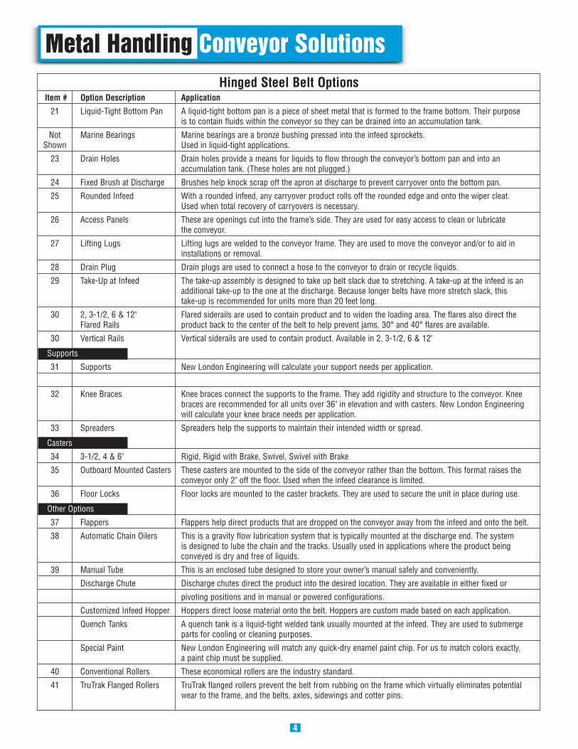
Metal Handling Conveyor SolutionsHinged Steel Belt Options
Item # Option Description Application
21 Liquid-Tight Bottom Pan A liquid-tight bottom pan is a piece of sheet metal that is formed to the frame bottom. Their purpose is to contain fluids within the conveyor so they can be drained into an accumulation tank.
Not Marine Bearings Marine bearings are a bronze bushing pressed into the infeed sprockets. Shown Used in liquid-tight applications.
23 Drain Holes Drain holes provide a means for liquids to flow through the conveyor’s bottom pan and into an accumulation tank. (These holes are not plugged.)
24 Fixed Brush at Discharge Brushes help knock scrap off the apron at discharge to prevent carryover onto the bottom pan.
25 Rounded Infeed With a rounded infeed, any carryover product rolls off the rounded edge and onto the wiper cleat. Used when total recovery of carryovers is necessary.
26 Access Panels These are openings cut into the frame’s side. They are used for easy access to clean or lubricate the conveyor.
27 Lifting Lugs Lifting lugs are welded to the conveyor frame. They are used to move the conveyor and/or to aid in installations or removal.
28 Drain Plug Drain plugs are used to connect a hose to the conveyor to drain or recycle liquids.
29 Take-Up at Infeed The take-up assembly is designed to take up belt slack due to stretching. A take-up at the infeed is an additional take-up to the one at the discharge. Because longer belts have more stretch slack, this take-up is recommended for units more than 20 feet long.
30 2, 3-1/2, 6 & 12" Flared siderails are used to contain product and to widen the loading area. The flares also direct the Flared Rails product back to the center of the belt to help prevent jams. 30° and 40° flares are available.
30 Vertical Rails Vertical siderails are used to contain product. Available in 2, 3-1/2, 6 & 12"
Supports
31 Supports New London Engineering will calculate your support needs per application.
32 Knee Braces Knee braces connect the supports to the frame. They add rigidity and structure to the conveyor. Knee braces are recommended for all units over 36" in elevation and with casters. New London Engineering will calculate your knee brace needs per application.
33 Spreaders Spreaders help the supports to maintain their intended width or spread.
Casters
34 3-1/2, 4 & 6" Rigid, Rigid with Brake, Swivel, Swivel with Brake
35 Outboard Mounted Casters These casters are mounted to the side of the conveyor rather than the bottom. This format raises the conveyor only 2" off the floor. Used when the infeed clearance is limited.
36 Floor Locks Floor locks are mounted to the caster brackets. They are used to secure the unit in place during use.
Other Options
37 Flappers Flappers help direct products that are dropped on the conveyor away from the infeed and onto the belt.
38 Automatic Chain Oilers This is a gravity flow lubrication system that is typically mounted at the discharge end. The system is designed to lube the chain and the tracks. Usually used in applications where the product being conveyed is dry and free of liquids.
39 Manual Tube This is an enclosed tube designed to store your owner’s manual safely and conveniently.
Discharge Chute Discharge chutes direct the product into the desired location. They are available in either fixed or
pivoting positions and in manual or powered configurations.
Customized Infeed Hopper Hoppers direct loose material onto the belt. Hoppers are custom made based on each application.
Quench Tanks A quench tank is a liquid-tight welded tank usually mounted at the infeed. They are used to submerge parts for cooling or cleaning purposes.
Special Paint New London Engineering will match any quick-dry enamel paint chip. For us to match colors exactly, a paint chip must be supplied.
40 Conventional Rollers These economical rollers are the industry standard.
41 TruTrak Flanged Rollers TruTrak flanged rollers prevent the belt from rubbing on the frame which virtually eliminates potentialwear to the frame, and the belts, axles, sidewings and cotter pins.
4

Metal Handling Sketch Diagrams
4. Flat Top Apron
3. Conventional Apron
5

Metal Handling Sketch Diagrams
6
TruTrak rollers are recommended for use in long run, heavy load applications and where prevention of downtime is priority.
41
40
1
2

1700 Division Street • New London, WI 54961800-437-1994 • 920-982-4030 • fax: 920-982-6800 • www.nleco.com
Hinged Steel Belt Specifications
Quality Conveyors Since 1948
Brochure #03-05/10884.71
All models are shown with 45° incline. Both 30° and 60° inclines are also available.
BW – 1 3/8"
BW
BW + 11 9/32"
BW + 18
38 3/4"
29"BW + 27 7/16"
BW
TOP MOUNT DRIVE
BW + 56
BW – 1 3/8"
BW
SIDE MOUNT DRIVE
27"
44"
21 3/4"
57"CW +3 1/4"CW
25 1/2"
25"
CW + 10"
CW
9"
31 1/2"
CW + 16"
CW
SIDE MOUNT DRIVE
TOP MOUNT DRIVE
11"
BW + 12"
BW
BW+ 7"
15 5/8"
TOP MOUNT DRIVE
35"
42"
BW + 20 1/2"
BW
BW+ 7"
24"
55" 22"
43 1/2'
BW + 26"
BW
BW+ 4"
SIDE MOUNT DRIVE
BW
BW +28 1/2"
Model 721 Model 722
Model 727Model 725
Model 715 Model 700
Model 760Model 711
Model 751