Highest Quality Post Drivers and Post Pullers GPD-45 this owner’s manual handy, ... GPD-45...
24
Highest Quality Post Drivers and Post Pullers Form No. 301801-08/2014 OWNERS MANUAL GPD-45 Gas Powered Driver Multi-Pro ™
Transcript of Highest Quality Post Drivers and Post Pullers GPD-45 this owner’s manual handy, ... GPD-45...

Highest Quality Post Drivers and Post Pullers
Highest Quality Post Drivers and Post Pullers
Form No. 301801-08/2014
Form No. 301801-08/2014
© 2014 Rhino Tool Company, Inc.
© 2014 Rhino Tool Company, Inc.
Rhino Tool Company620 Andrews Avenue
Kewanee, IL 61443P: 309.853.5555 or Toll Free 866-707-1808
F:309.856.5905www.rhinotool.com E: [email protected]
Rhino Tool Company620 Andrews Avenue
Kewanee, IL 61443P: 309.853.5555 or Toll Free 866-707-1808
F:309.856.5905www.rhinotool.com E: [email protected]
Manufacturing Quality Post Drivers and Post Pullers Since 1977
Manufacturing Quality Post Drivers and Post Pullers Since 1977
O W N E R S M A N U A L
O W N E R S M A N U A L
GPD-45Gas Powered DriverMulti-Pro™
GPD-45Gas Powered DriverMulti-Pro™

i
i
Your safety, and the safety of others, is very important. The proper and safe use of your Rhino® post driver is an important
responsibility and should be taken seriously.
This entire book is filled with important safety information. Please read it carefully.
Keep this owner’s manual handy, so you can refer to it at any time. This owner’s manual is considered a
permanent part of the post driver and should remain with the post driver if resold.
The information and specifications includ-ed in this publication were in effect at the time of approval for printing. Rhino Tool Company, Inc. reserves the right, however, to discontinue or change specifications or design at any time without notice and with-out incurring any obligation whatever. No part of this publication may be reproduced without written permission from Rhino Tool Company.
To help you make informed decisions about safety, you will find important safety information in a variety of forms, including:
• Safety Labels on the post driver
• Safety Messages Preceded by a safety alert symbol and one of three signal words, DANGER, WARNING, or CAUTION.
These signal words mean:
! WARNING
! DANGER
! CAUTION
IMPORTANT
NOTE
Immediate hazards that will result in
severe personal injury or death.
! WARNING
! DANGER
! CAUTION
IMPORTANT
NOTE
Hazards or unsafe practices that could
result in personal injury.
! WARNING
! DANGER
! CAUTION
IMPORTANT
NOTE
Hazards or unsafe practices that could result in injury,
product or property damage.• Safety Headings such as IMPORTANT SAFETY INFORMATION.
• Safety Section such as POST DRIVER SAFETY.
• Instructions how to use this post driver correctly and safely.
TAKE SAFETY SERIOUSLY
TAKE SAFETY SERIOUSLY
GPD-45 Multi-Pro™ Trouble Shooting
GPD-45 Multi-Pro™ Trouble Shooting
21
21
Post lodged in driver with adapter installed: Turn off the engine. Remove the Chuck-Lok™ System’s locking nut from the master chuck and slide down the post. Using the handles, lift post driver upward, allowing the post adapter to slide out. If the pressure from the flared post does not allow you to lift driver off the post, locate the pry gaps on the adapter base and use a flathead screwdriver to pry them downward. Be careful not to damage the master chuck threads. Once loosened, lift using the post driver handles. As the two-piece adapter frees from the chuck tube they separate from the post. Slide the locking nut off the post, reinsert the adapter, apply the locking nut and resume post driving.
Post lodged in master chuck: Remove the four GPD bolts and separate the master chuck from lower body. Slide the master chuck down the post to expose the flared top of the post. With the proper cutting tool for the type of post, cut through the post below the flared portion. Once the flared portion is removed, slide the master chuck off the post and reassemble it to the driver. Please follow bolt tightening procedure and use thread locker solution. Recommendation: Do not use “thin-wall” or light gauge round post with the GPD-45 Multi-Pro™. It is very likely to flare this type of post at full throttle.
Drives post slow or sluggish engine performance: Typically this is resulting from improper driver storage or over-filling the oil causing the oil to seep into the combustion chamber. Turn off the engine. Position the driver vertically, remove the dipstick to check oil level. (See page 6) If you need to remove some oil, dispose of it properly. If oil is at proper level, follow the procedure listed in “Pull-start is frozen or hard to pull.” It also is good practice to wipe clean the engine after use.
Pull-start is frozen or hard to pull: This typically results from oil seeping into the combustion chamber from improper driver storage or overfilling the oil reservoir of the engine. Remove spark plug and pull hand grip a several times until it pulls freely. Replace the spark plug. Check the oil level in oil reservoir to ensure proper level (page 6). Follow starting procedure. It is not unusual, for blue smoke to be emitted from the engine, let the engine run until smoke clears.
Proper Storage: When storing your GPD-45, do not lay it horizontally on the driver side or resting on the engine. If the unit cannot be stored securely in the upright position, place the chuck on the flat surface, lean it toward the engine side until it is supported by the shroud and chuck. This will position the driver on an angle with the top handle at the topmost point.
Other problems or technical questions: Have your serial number handy and contact Rhino Tool Company. Phone: 309.853.5555 or Toll Free 866-707-1808, Fax:309.856.5905, Email: [email protected]
Post lodged in driver with adapter installed: Turn off the engine. Remove the Chuck-Lok™ System’s locking nut from the master chuck and slide down the post. Using the handles, lift post driver upward, allowing the post adapter to slide out. If the pressure from the flared post does not allow you to lift driver off the post, locate the pry gaps on the adapter base and use a flathead screwdriver to pry them downward. Be careful not to damage the master chuck threads. Once loosened, lift using the post driver handles. As the two-piece adapter frees from the chuck tube they separate from the post. Slide the locking nut off the post, reinsert the adapter, apply the locking nut and resume post driving.
Post lodged in master chuck: Remove the four bolts and separate the master chuck from lower body. Slide the master chuck down the post to ex-pose the flared top of the post. With the proper cutting tool for the type of post, cut through the post below the flared portion. Once the flared portion is removed, slide the master chuck off the post and reassemble it to the driver. Please follow bolt tightening procedure and use thread locker solution. Recommendation: Do not use “thin-wall” or light gauge round post with the GPD-45 Multi-Pro™. It is very likely to flare this type of post at full throttle.
Drives post slow or sluggish engine performance: Typically this is resulting from improper driver storage or over-filling the oil causing the oil to seep into the combustion chamber. Turn off the engine. Position the driver vertically, remove the dipstick to check oil level. (See page 6) If you need to remove some oil, dispose of it properly. If oil is at proper level, follow the procedure listed in “Pull-start is frozen or hard to pull.” It also is good practice to wipe clean the engine after use.
Pull-start is frozen or hard to pull: This typically results from oil seeping into the combustion chamber from improper driver storage or overfilling the oil reservoir of the engine. Remove spark plug and pull hand grip a several times until it pulls freely. Replace the spark plug. Check the oil level in oil reservoir to ensure proper level (page 6). Follow starting procedure. It is not unusual, for blue smoke to be emitted from the engine, let the engine run until smoke clears.
Proper Storage: When storing your GPD-45 Multi-Pro™, do not lay it horizontally on the driver side or resting on the engine. If the unit cannot be stored securely in the upright position, place the chuck on the flat surface, lean it toward the engine side until it is supported by the shroud and chuck. This will position the driver on an angle with the top handle at the topmost point.
Other problems or technical questions: Have your serial number handy and contact Rhino Tool Company. Phone: 309.853.5555 or Toll Free 866-707-1808, Fax:309.856.5905, Email: [email protected]

1© 2014 Rhino Tool Company Inc., - All Rights Reserved
CONTENTSSection Page
Safety Symbol Description . . . . . . . . . . . i
Table of Contents . . . . . . . . . . . . . . . . . . . .1
Introduction . . . . . . . . . . . . . . . . . . . . . . . . . .1
Rhino® GPD-45 Multi-Pro™ Driver Safety . . . . . . . . . . . . . . . . . . . . . . . . .2
Rhino® GPD-45 Multi-Pro™ Operating Instructions . . . . . . . . . . . . . . .4
Starting the Engine . . . . . . . . . . . . . . . . . . .5 Hot Restart . . . . . . . . . . . . . . . . . . . . . . . . . .6 Driving a Post . . . . . . . . . . . . . . . . . . . . . . . .7 GPD-45 Multi-Pro™ Maintenance . . . . . . .9
Rhino® GPD-45 Multi-Pro™ Service Instructions . . . . . . . . . . . . . . . . . .9
Servicing Crankshaft and Piston . . . . . . 10 Service of the Hammer and Anvil . . . . . 11
Rhino® GPD-45 Multi-Pro™ Parts & Accessories List . . . . . . . . . . . 15
Limited Warranty and Registration . . . . . . . . . . . . . . . . . . . 20
Troubleshooting . . . . . . . . . . . . . . . . . . . 21
INTRODUCTIONCongratulations on your selection of the Rhino® GPD-45 Multi-Pro™ post driver. We are certain that you will be pleased with your purchase. This post driver was built with the Honda GX35 engine. Honda supplies its own owner’s manual that covers all the operator and service issues associated with the Honda engine. Please read this manual as closely as you do the Rhino manual. The success that you ex-perience with this tool is dependent upon your knowledge and understanding of how to properly operate and care for the Honda engine installed on your new post driver.
As you read this manual, you will find in-formation preceded by a NOTICE symbol. That information is intended to help you avoid damage to your post driver, other property, or the environment.
We suggest you read the warranty infor-mation fully and understand its coverage and your responsibilities of ownership. Fill out the warranty registration card or online registration to receive Rhino® Lifetime Limited Warranty. (See Page 20) Please
read and understand the Honda warranty policy. The Honda warranty is separate from the Rhino® warranty and is subject to its own coverage conditions and respon-sibility requirements. The warranty is a separate document and is included with the Honda owner’s manual.
When your Rhino® post driver needs scheduled maintenance, the technical service staff here at Rhino Tool Company is standing by to assist you.. Our fully trained staff can ensure that you receive the correct service kit or direct you to the nearest Rhino Servicing Dealer.
The engine requires scheduled mainte-nance, keep in mind that your Honda ser-vice dealer is fully equipped and specially trained in servicing the Honda engine. Your Honda servicing dealer is dedicated to your satisfaction, and will be pleased to answer your questions and concerns.

2
The Rhino® GPD-45 Multi-Pro™ gas pow-ered driver is designed to drive fence post, ground rod, delineator post, grape stake, form pin, tent stake and other like items into the ground. Uses, other than those intended, can result in injury to the opera-tor as well as those around the operator. Damage to the driver and to the surround-ing area may result as well.This post driver is intended for use by pro-fessional installers. Never allow children to operate this tool.Most accidents can be prevented if you follow all instructions in this manual and on the post driver. The most common haz-ards are discussed below, along with the best method to protect yourself and others.
UNDERGROUND UTILITIES: Driving
a post into an underground utility can be EXTREMELY DANGEROUS, exposing the operator and those around to poten-tially life threatening danger. Damage to surrounding property can also occur as a result of a post being driven into an under-
ground utility. Be absolutely certain that you are aware of all underground utilities in the area in which you intend to drive posts. Ensure that a certified locating ser-vice has identified all underground utilities prior to beginning your project. Failure to do so can be catastrophic. Underground utilities include but are not limited to: Electric, Gas, Telephone, Water, Sewer, TV Cable, Lawn Sprinklers, etc.
GASOLINE: Gasoline is HIGHLY FLAM-
MABLE and EXPLOSIVE. You can be burned or seriously injured when handling fuel.
EXHAUST: The ex-haust from the engine
contains poisonous carbon monoxide gas that can build up to dangerous levels in closed areas. Breathing carbon monoxide can cause unconsciousness or death. Never run the engine in a closed or even partly closed area where people may be present.
The engine exhaust from this product
contains chemicals known to the State of California to cause cancer, birth defects or other reproductive harm.
ENGINE MAINTENANCE:
Improperly maintaining the engine on this power tool, or failure to correct a problem before operation, can cause a malfunc-tion in which you can be seriously hurt or killed.In accordance with the engine owner’s manual, always perform a pre-operation inspection of the engine before each use and correct any problem.
DRIVER MAINTENANCE:
Improperly maintaining the driving mechanism on this power tool, or failure to correct a problem before operation, can cause a malfunction in which you can be seriously hurt or killed.In accordance with this manual, always
IMPORTANT SAFETY INFORMATIONPOST DRIVER SAFETY
! WARNING
! DANGER
! CAUTION
IMPORTANT
NOTE
! WARNING
! DANGER
! CAUTION
IMPORTANT
NOTE
! WARNING
! DANGER
! CAUTION
IMPORTANT
NOTE
! WARNING
! DANGER
! CAUTION
IMPORTANT
NOTE
! WARNING
! DANGER
! CAUTION
IMPORTANT
NOTE
! WARNING
! DANGER
! CAUTION
IMPORTANT
NOTE
3
perform a pre-operation inspection of the driving mechanism before each use and correct any problem.
Do not lend or rent your post driver with-
out the instruction manuals. Be sure that anyone using it understands the informa-tion contained in these manuals.
Do not use this post driver for any purpose
other than driving posts into the ground. Misuse may result in personal injury or property damage, including damage to the machine
Minors should never be allowed to use this
power tool. Bystanders, especially chil-dren, and animals should not be allowed in the area where it is in use.
NEVER let your power tool run unat-
tended. When it is not in use, shut it off and make sure that unauthorized persons do not use it.
Do not operate this post driver unless the
operator is wearing safety glasses, safety shoes, hearing protection, gloves or any other safety equipment advised by, ANSI, NIOSH, OSHA, or any other safety regu-latory agency, the employer or the owner of this post driver.Bystanders should, at a minimum, wear safety glasses and hearing protection while in the presence of this power tool during operation.
Prolonged use of a power tool (or other
machines) exposing the operator to vibra-tions may produce white finger disease (Raynaud’s phenomenon) or carpal tunnel syndrome. These conditions reduce the hand’s ability to feel and regulate tem-perature, produce numbness and burning sensations and may cause nerve and circu-lation damage and tissue necrosis.Not all factors contributing to white finger disease are known, but cold weather, smoking and diseases or physical condi-
tions that affect blood vessels and blood transport, as well as high vibration levels and long periods of exposure to vibration are mentioned as factors in the develop-ment of white finger disease. In order to reduce the risk of white finger disease and carpal tunnel syndrome, please note the following:• The Rhino GPD-45 Multi-Pro™ has been
designed with Rhino® CIS™ anti-vibra-tion handles to reduce the transmission of vibrations created by the machine to the operator’s hands.
An anti-vibration system is recommend-ed for those persons using power tools on a regular or sustained basis.
• The handle opposite the throttle handle has been fitted with an EVA foam grip further dampening vibrations.
• Wear gloves and keep your hands warm.• Ensure that the EVA foam and the
spring dampening system are in good working condition.
IMPORTANT SAFETY INFORMATIONPOST DRIVER SAFETY... continued
! WARNING
! DANGER
! CAUTION
IMPORTANT
NOTE
! WARNING
! DANGER
! CAUTION
IMPORTANT
NOTE
! WARNING
! DANGER
! CAUTION
IMPORTANT
NOTE
! WARNING
! DANGER
! CAUTION
IMPORTANT
NOTE
! WARNING
! DANGER
! CAUTION
IMPORTANT
NOTE
! WARNING
! DANGER
! CAUTION
IMPORTANT
NOTE

• Ensure the post driver has no loose com-ponents. Loose components lead to high vibration levels.
• Maintain a firm grip at all times, but do not squeeze the handles with constant, excessive pressure. Take frequent breaks.
All of the above mentioned precautions do not guarantee that you will not sustain white finger disease or carpal tunnel syn-drome. Therefore, continual and regular users should closely monitor the condi-tion of their hands and fingers. If any of the above symptoms appear, seek medical advice immediately.
DO NOT modify this power tool in any way.DO NOT put anything other than a post into
the chuck on the driver.DO NOT operate your post driver unless it
is on a post to be driven. Operation of the
driver without it driving on a post could damage the power tool.
SURROUNDINGS: This power tool emits
noise which may be disturbing to animals and livestock. Ensure prior to operation, that any livestock are cleared from the operational area to prevent a situation in which startled livestock become a safety hazard.WARNING LABELSIf your post driver’s warning label is marred or destroyed, replace it immedi-ately. Simply call Rhino Tool Company and we will send you a new warning label at no expense to you.
POST DRIVER SAFETY... continuedIMPORTANT SAFETY INFORMATION
! WARNING
! DANGER
! CAUTION
IMPORTANT
NOTE
! WARNING
! DANGER
! CAUTION
IMPORTANT
NOTE
! WARNING
! DANGER
! CAUTION
IMPORTANT
NOTE
! WARNING
! DANGER
! CAUTION
IMPORTANT
NOTE
GPD-45 Multi-Pro™ Operating InstructionsYour Rhino® GPD-45 Multi-Pro™ Gas Powered Driver is an efficient and effec-tive power tool designed and developed to tackle a difficult and time consuming task; driving posts.
It is very important to understand that your post driver is a very powerful ma-chine; it has to be to do the very difficult job it is designed to perform. With proper care and maintenance, your Rhino® GPD-45 Multi-Pro™ will give you many years of trouble free service.
You must read and understand your post driver operating instructions before using the post driver. It is also very important that you make sure all operators are trained to operate your post driver safely. If you or any operator doesn’t understand any of the instructions in this manual, call Rhino Tool Company at 866-707-1808 or 309-853-5555 and we will assist you with any questions you may have.
4

5
AVOID SERIOUS INJURY OR DEATH
READ THIS MANUAL BEFORE USING YOUR POST DRIVERVisually inspect your GPD-45 Multi-Pro™ Post Driver before use. The interior of the chuck tube should be checked for obstruc-tions, damage or wear to the chuck tube and anvil inside. The outer surfaces of the
driver should also be inspected for any de-fects. Do not use the GPD-45 Multi-Pro™ if there is any damage or wear until the damage or wear is corrected and repaired.
Check all fluid levels, i.e. engine oil and fuel and fill as needed as per manufac-turer’s specifications.
Proper oil level is essential to the operation of the post
driver. Overfilling of the oil will result in loss of power and may cause perma-nent damage to the engine.
USE ALL RECOMMENDED
SAFETY EQUIPMENT.Rest the driver on a solid surface, i.e. tailgate, bench, or clear, solid ground and posture your body in a safe position. DO NOT start the driver anywhere but an open, well-ventilated area. It is recom-mended that the GPD-45 Multi-Pro™ only be used outdoors and never inside an enclosed building.
Starting the Engine:
To start a COLD engine, move the choke lever to the CLOSED position (Fig. 3). Lock the throttle into high idle position. (Fig. 2) This is done by depressing the trigger and the high idle lock simultane-ously. The throttle is now in the high idle position.
To start a WARM engine, leave the choke lever in the OPEN position and do not lock the throttle into the high idle position.
Press the priming bulb repeatedly (Fig. 4)until fuel can be seen in the clear-plastic fuel return tube.
Slide thumb switch on throttle handle down or into the ON position.
GPD-45 Multi-Pro™ Operating Instructions... continued
! WARNING
! DANGER
! CAUTION
IMPORTANT
NOTE
! WARNING
! DANGER
! CAUTION
IMPORTANT
NOTE
! WARNING
! DANGER
! CAUTION
IMPORTANT
NOTE
Upper limit of engine oil.Lower limit of engine oil is end of dipstick.Fig. 1
Thumb Switch
High Idle Lock
Trigger
Fig. 2

6
Grasp the starter grip lightly until you feel resistance, then pull briskly in the direction of the arrow as shown in Fig. 5. Return the starter grip gently.
Do not extend the starter rope to its full length as it can cause damage the recoil mechanism
An operator should never wrap the starter
rope around their hand. This will cause serious injury.
Do not allow the starter grip to snap back against the
engine. Return it gently to prevent damage to the starter. If the choke lever was moved to the CLOSED position to start the engine, gradually move it to the open position as the engine warms up. As the engine warms up also release the high idle lock by slightly depressing the trigger and then immediately releasing it. Use caution as to not engage the clutch.
Hot Restart
If the engine is operated at higher ambient temperatures, then turned off and allowed to sit for a short time, it may not restart on the first pull. If necessary, use the follow-ing procedure:
Failure to follow instructions can result in personal injury
IMPORTANT SAFETY
PRECAUTIONTurn the engine switch to the OFF position before performing the following procedure. This will prevent the engine from starting and running at maximum speed when the throttle is in the MAX. speed position. If the engine starts with the throttle in the MAX. speed position, the post driver will operate at maximum power. This may result in personal injury and damage to the post driver.
1. Turn the engine switch on the post driver to the OFF position.
2. Move the choke lever to the OPEN position.
! WARNING
! DANGER
! CAUTION
IMPORTANT
NOTE
! WARNING
! DANGER
! CAUTION
IMPORTANT
NOTE
! WARNING
! DANGER
! CAUTION
IMPORTANT
NOTE
GPD-45 Multi-Pro™ Operating Instructions... continued
Choke Closed
Choke OpenFig. 3
Priming Bulb
Fuel Return Line (clear plastic tube)Fig. 4
Starter Grip
Fig. 5

7
3. Hold the throttle in the MAX speed position.
4. Pull the starter grip 3 to 5 times.
Follow the STARTING THE ENGINE procedure on the previous page and start the engine with the choke lever in the OPEN position.
DO NOT OPEN CRANKCASE COV-
ER WHILE ENGINE IS RUNNING.
Driving a Post
Insert a post into the GPD-45 Multi-Pro™ making sure the end of the post to be driven is in the correct position on the ground. Position the driver aligned centered to the post. (Fig. 6) If not aligned properly, damage could be caused to the driver or the post.
Apply steady downward pressure to the handles and apply enough throttle to en-gage the clutch and hammer.
Once you are confident that the post is driving straight, apply full throttle to the driver until the post is driven to the desired depth.
Release the trigger dropping the engine RPM back to idle before removing from the post. When the engine has returned to idle, proceed to the next post repeating the previous method of driving a post.
Installing a Chuck AdapterCHUCK SIZE: A chuck or chuck adapter
that is too large for the post being driven may damage the driver and may damage
the end of the post. Using a the appropri-ate chuck or chuck with adapter will align the post to optimum striking position and prevent damage to the driver. See the chart below to specify the appropriate adapter for your application. Chucks and chuck adapters wear out and should be replaced as needed. Inspect your driver’s chuck and
! WARNING
! DANGER
! CAUTION
IMPORTANT
NOTE
GPD-45 Multi-Pro™ Operating Instructions... continued
Type or Size of Post to be Driven
Chuck/Accessory Required
Fiberglass T-Post 2" Adapter
T-Post 2" Adapter
5/8" to 3/4" Ground Rod 1" Adapter
Tent Stake Tent Stake Chuck***
Concrete Form Pin 1" Adapter
1" to 1-7/8" Post 2" Adapter
2" to 2-3/8" Post Master Chuck
1-1/2" to 2-1/2" Square post and Square Post Sign Anchor
Chuck and Drive Cap***
1.2 - 4 lb Channel Post and Channel Post Sign Anchor
Channel Chuck***
PostDriver
Post
RIGHT WRONGFig. 6
*** Contact Rhino Tool Company for more detailsNote: Custom chucks may be available for your specific application contact Rhino Tool Company.
! WARNING
! DANGER
! CAUTION
IMPORTANT
NOTE

8
chuck adapters frequently.
The GPD-45 Multi-Pro is equipped with the Rhino® Chuck-Lok™ Adapter System. It is comprised of the master chuck, the locking nut and two-piece adapters.
ALWAYS HAVE THE LOCKING NUT IN
PLACE WHEN DRIVING POSTS: When equipped with the round master chuck, the Chuck-Lok™ locking nut should always be tightened onto the chuck to protect the chuck threads, even when not using an adapter. Failure to do so exposes the chuck to possible damage.
The two-piece adapter design is a solu-tion for the occasional flared post. Should
a post flare and lodge inside the chuck when using the adapter, in most cases the operator can loosen the locking nut letting it slide down the post, then lift the driver off the post. The operator can quickly re-insert the adapter, secure them with the locking nut and resume driving posts. See the Fig. 7 for steps for installing Chuck-Lok™ adapters.
Installing an Alternative ChuckThe GPD-45 Multi-Pro quick change de-sign allows the operator to quickly remove the standard master chuck and install alternative chuck configuration for your post driving application.
Turn off the engine and allow it to cool. Position the post driver on a work bench or level surface. Using a 3/16" hex bit socket wrench loosen and remove the 4 chuck bolts (p/n 300715) and compression washers (p/n 517801). Replace
compression washers if they are worn. Remove the chuck and set it aside in a convenient place to store until needed.
Align the alternate chuck to the bolt holes on the lower body, taking into account the position of slots or internal configuration for the post to insert according to the op-erator side of the post driver. Insert bolts through new compression washers into the bolt holes, snug into position and then tighten them in a crossing pattern with a torque wrench set to 132 inch/pounds torque them accordingly.
If alternative anvil parts are needed please follow the instructions provided with alternative chuck .
If you do not see a chuck option for a specific post, contact your Rhino Tool Company representative to inquire if there is an option available.
! WARNING
! DANGER
! CAUTION
IMPORTANT
NOTE
GPD-45 Multi-Pro™ Operating Instructions... continued
Fig. 7 - Hand tighten ONLY. No Tools.

9
GPD-45 Multi-Pro™ Operating Instructions... continuedMaintenance of the GPD-45 Multi-Pro™
NEVER REFUEL WITH THE ENGINE
HOT OR RUNNING:Never refuel your GPD-45 Multi-Pro™ with the engine hot or running as there is a possibility the flammable fumes from the gasoline can ignite, causing severe injury and/or damage to your GPD-45 Multi-Pro™ and surrounding area. Follow engine manufacturer’s instructions for the refuel-ing of the engine.
With each use check the engine oil level, air filter, and all fasteners. If necessary, add oil, clean or replace the air filter and tighten any loose nuts, bolts, or any other fastener. (See page 6 for engine oil level)
Change engine oil as per engine manu-facturer’s specifications. Dispose of used oil in accordance with any local, state, or federal regulations.
To help insure years of operation, wipe down the GPD-45 Multi-Pro™ with a clean cloth after each days use.
Refer to the Service Instructions for more detail regarding maintenance of the Post Driver.
GPD-45 Multi-Pro™ Service InstructionsFollowing the service requirements for the GPD-45 Multi-Pro™ will insure years of trouble free post driving. Always refer to the Honda GX35 manual for maintenance and service on the engine. The following instructions are for the Rhino® GPD-45 Multi-Pro™ specifically with general instructions for the Honda GX35. Before any service is preformed, remove the spark plug wire from the spark plug and ground it to the engine body to prevent any accidental start-up of the engine.Each Use:1. Check engine oil level. Use SAE 10W-
30 to top oil level off, if necessary.2. Check engine air cleaner. If soiled,
clean or replace.
3. Check all engine and post driver fasten-ers. Retighten to proper specifications if necessary. (See Bolt Torque Specifica-tions on page 19)
First 10 Hours Use of a New or Rebuilt GPD-45 Multi-Pro™
1. Change engine oil following the requirement for the Honda GX35. Dis-pose of used oil according to all local, state, and federal regulations.
2. Check all engine and post driver fasten-ers. Retighten to proper specifications if necessary.
Every 3 Months or 25 Hours of Use1. Change engine oil following the
requirement for the Honda GX35. Dis-pose of used oil according to all local, state, and federal regulations.
2. Replace air cleaner elements. This should be performed more often if oper-ated in dusty areas.
3. Check all engine and post driver fasten-ers. Retighten to proper torque specifi-cations if necessary. (See page 19)
! WARNING
! DANGER
! CAUTION
IMPORTANT
NOTE

GPD-45 Multi-Pro™ Service Instructions... continued
10
Every 3 Months or 50 Hours of Use1. Follow the regular scheduled mainte-
nance (each use and 25 hour intervals)2. Check crankshaft and piston lubrica-
tion. (See page "Servicing for instruc-tions.)
Every 12 Months or 250 Hours of Use1. Follow the regular scheduled mainte-
nance (each use, 25 hour and 50 hour intervals)
2. Check crankshaft and piston lubrica-tion. (See page 10 for instructions.)
3. Remove and service the hammer and anvil. (See page 11 for instructions.)
Servicing Crankshaft and Piston LubricationThe crankcase cover (p/n 300132) is designed for easy, “no tool” inspection and maintenance. (Fig. 8). To remove the cover, grip it tightly with your hand and twist it left (counter-clockwise.) Use cau-tion not to lose or damage the O-ring Seal (p/n 301617).
DO NOT OPEN CRANKCASE COV-
ER WHILE ENGINE IS RUNNING DO NOT USE A HAMMER OR
WRENCH TO LOOSEN THE COVER AS IT MAY CAUSE DAMAGE TO THE DRIVER. Visually inspect the color and amount of grease inside the crankcase. There should be a ring of grease collected to the wall in-side the crankcase. Should the depth of the ring from the wall inward measure 1/4"
(6 mm) or less (Fig. 9) this indicates the grease is low. The maximum level should not be more than 1/2" (12.5mm).If the amount of grease appears to be low, add a small amount of grease. Use only Rhino approved grease (p/n 300500.)
DO NOT OVERFILL GREASE AS IT CAN
DAMAGE THE DRIVER AND THE HONDA ENGINE. If the grease is discolored, very dark or black, it should be removed and the post
Fig. 8 - Crankcase Cover
Fig. 9 - If ridge of grease measures 1/4″ or less, add a small amount. At maximum level it should measure 1/2".
! WARNING
! DANGER
! CAUTION
IMPORTANT
NOTE
! WARNING
! DANGER
! CAUTION
IMPORTANT
NOTE
! WARNING
! DANGER
! CAUTION
IMPORTANT
NOTE

11
driver needs further maintenance. This is detailed in the section titled “Service of the Hammer and Anvil.”In the event of complete removal of old and adding fresh grease (Fig. 10) the level of grease should be to the bottom edge of the crank pin head. When the required ser-vice has been performed in the crankcase, inspect the o-ring seal and replace it on the crankcase cover. Position the crankcase cover on the GPD-45 Multi-Pro™ body carefully to start the threads and once in
the thread groove, with your hand twist to the right (clock-wise) until it is securely in contact with the post driver body.
HAND TIGHTEN ONLY. DO NOT
OVERTIGHTEN. Do not use tools, such as a hammer or wrench, to tighten the crankcase cover as it will damage the driver.
Service of the Hammer and AnvilThe tools required for servicing the ham-mer and anvil are, a 9/64″ hex wrench, a 1/4″ hex wrench, a 7/8″ deep well socket with handle, a torque wrench that reads in inch/pounds, and Loctite primer and threadlocker.
Remove the crankcase cover (see crankcase cover warning on page 10) and clean out any old grease from inside the crankcase.Remove the four (4) chuck bolts (p/n 300715) and disconnect the chuck. Re-move the four (4) lower bolts (p/n 300702) from the lower driver body and the four (4) bolts (p/n 300715) from the upper handle bracket. Use caution as the handle tubes have four (4) anti-vibration springs (p/n 610010) installed and under tension. Grasping the upper handle bracket pull it directionally away from the driver body to create a separation between them. While separated, lift and remove the upper driver body assembly (p/n 301016) from the post driver assembly and set aside. Observe the lower driver body, it should appear as shown in Fig. 11. The anvil o-ring retainer (p/n 301115) will sometimes drop out with the lower driver body or remain in place at the base of the cylinder of the upper driver body.Remove the anvil o-ring cup (p/n 301095) and the anvil (p/n 301165). This can be
GPD-45 Multi-Pro™ Service Instructions... continued
Fig. 10 - After completely cleaning out old grease, add new grease till level with the bottom edge of the crank pin head.
! WARNING
! DANGER
! CAUTION
IMPORTANT
NOTE
Fig. 11 - View when Lower Driver Body removed.
12
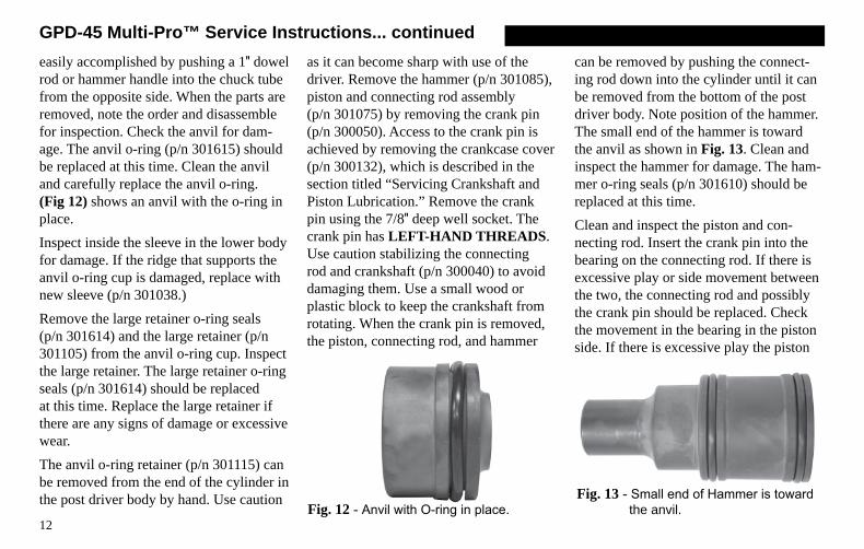
easily accomplished by pushing a 1″ dowel rod or hammer handle into the chuck tube from the opposite side. When the parts are removed, note the order and disassemble for inspection. Check the anvil for dam-age. The anvil o-ring (p/n 301615) should be replaced at this time. Clean the anvil and carefully replace the anvil o-ring. (Fig 12) shows an anvil with the o-ring in place.Inspect inside the sleeve in the lower body for damage. If the ridge that supports the anvil o-ring cup is damaged, replace with new sleeve (p/n 301038.) Remove the large retainer o-ring seals (p/n 301614) and the large retainer (p/n 301105) from the anvil o-ring cup. Inspect the large retainer. The large retainer o-ring seals (p/n 301614) should be replaced at this time. Replace the large retainer if there are any signs of damage or excessive wear.The anvil o-ring retainer (p/n 301115) can be removed from the end of the cylinder in the post driver body by hand. Use caution
as it can become sharp with use of the driver. Remove the hammer (p/n 301085), piston and connecting rod assembly (p/n 301075) by removing the crank pin (p/n 300050). Access to the crank pin is achieved by removing the crankcase cover (p/n 300132), which is described in the section titled “Servicing Crankshaft and Piston Lubrication.” Remove the crank pin using the 7/8″ deep well socket. The crank pin has LEFT-HAND THREADS. Use caution stabilizing the connecting rod and crankshaft (p/n 300040) to avoid damaging them. Use a small wood or plastic block to keep the crankshaft from rotating. When the crank pin is removed, the piston, connecting rod, and hammer
can be removed by pushing the connect-ing rod down into the cylinder until it can be removed from the bottom of the post driver body. Note position of the hammer. The small end of the hammer is toward the anvil as shown in Fig. 13. Clean and inspect the hammer for damage. The ham-mer o-ring seals (p/n 301610) should be replaced at this time.Clean and inspect the piston and con-necting rod. Insert the crank pin into the bearing on the connecting rod. If there is excessive play or side movement between the two, the connecting rod and possibly the crank pin should be replaced. Check the movement in the bearing in the piston side. If there is excessive play the piston
GPD-45 Multi-Pro™ Service Instructions... continued
Fig. 13 - Small end of Hammer is toward the anvil.Fig. 12 - Anvil with O-ring in place.

assembly should be replaced. The pis-ton o-ring seal (p/n 301610) should be replaced at this time. See Fig. 14.Clean and inspect the cylinder and crank-case for any damage or wear. Replace any damaged parts. Lubricate the cylinder, piston, and connecting rod with Rhino approved grease. Insert the connecting rod, of piston assembly, into the cylinder. Push the piston up the cylinder until the bearing in the connection rod aligns with the threaded hole for the crank pin. Apply Loctite primer and threadlocker to the crank pin. Insert the crank pin through the bearing and start the threads into the crankshaft by hand. Use caution holding the connecting rod and crankshaft (p/n 300040). The connecting rod and crank-
shaft can be damaged. Use a small wood or plastic block to keep the crankshaft from rotating. These are LEFT-HAND THREADS. Tighten the crank pin using the 7/8″ deep well socket. Torque to 228 inch/pounds. Add Rhino approved grease (p/n 300500) to the crankcase to the level shown in Fig. 10. (See Caution: Do not overfill grease on page 11) If grease has been completely removed add one (1) tube of Rhino® Post Driver Grease (2.75 oz.) or until level with the bottom of the crankpin head. Close the crankcase by placing the crankcase cover o-ring seal onto the crankcase cover. Place the crankcase cover onto the post driver body, start the thread, and twist to the right (clockwise) with your hand until it is secure against the post driver body. (See Caution: Hand Tighten Only on page 11)Lubricate the hammer with Rhino grease. Insert the hammer into the cylinder, taking note of the small end toward the anvil as shown in Fig. 13. Push the hammer into
the cylinder making room to insert the anvil o-ring retainer. Apply grease to the anvil o-ring retainer and place the small end into the cylinder. The grease should hold it in place.Lubricate and assemble the large retainer
13
GPD-45 Multi-Pro™ Service Instructions... continued
Fig. 14 - Piston with Connecting Rod and O-ring Seal in place.
Fig. 15 - Insert O-ring into Anvil O-ring Cup, then insert Large Retainer (with large radius up), then insert other O-ring.
O-ring
O-ring
Anvil O-ring Cup
Anvil withO-ring
Large Retainer
Large Radius (up)

and the two (2) large retainer o-ring seals in the order shown in Fig. 15 and assem-ble into the anvil o-ring cup.Clean and inspect the lower driver body (p/n 301032) for any damage or exces-sive wear. Replace if necessary. Lubricate inside of the sleeve of the lower body with grease. Lubricate the anvil with grease. Insert the anvil with new anvil o-ring into lower body, making certain that the anvil is seated into the lower body. Insert the anvil o-ring cup into the lower body. Dis-card the o-ring cup o-ring (p/n 301618). and body gasket (p/n 301710) replace with new o-ring and gasket. It should look like Fig. 11.Grasping the upper handle bracket pull toward the upper handle and seat the upper driver body onto the lower body. Gently let the upper handle bracket slide back into place. Align the bolt holes of the body assembly to those of the lower body. Apply Loctite primer and threadlocker to the upper handle and lower body bolts. Insert and hand thread the four (4) Lower body bolts through the lower driver body
into the post driver body. Use a 1/4″ hex wrench to tighten the bolts in a star pattern until the lower driver body is seated on the post driver body. Check for any misalign-ment or binding when joining the parts not use excessive force. Then hand thread the four (4) upper handle bolts and tighten in a star pattern with a 9/64" hex wrench. Torque the upper handle and lower body bolts to 132 inch/pounds. Apply Loctite primer and threadlocker to the chuck bolts. Slide compression wash-ers, or if worn, new compression washers onto the chuck bolts. Align the chuck to the bolt holes of the lower body and insert the chuck bolts and tighten them into place in a crossing pattern. Then torque them to 132.0 inch/pounds. To clean and lubricate the anti-vibration handle springs loosen the two bolts located in the recesses upper handle assembly (p/n 301222) until the upper handle and handle collars are free from the upper handle bracket. Slide the lower handle downward to expose the lower springs. Clean the springs, upper handle bracket cups, and
upper and lower handle collars. Apply Rhino grease to springs, right and left collars of the lower handle, top cups of the upper handle bracket, and upper handle collars. Slide the lower handle assembly back up into position. Apply primer and threadlocker to the upper handle bolts, insert the springs into the upper handle bracket cups. Then insert the upper handle with collars on top of the springs depress-ing them into the handle bracket cups and tighten the bolts to secure the handle into place. Using a torque wrench set to 132.0 inch/pounds torque the upper handle bolts accordingly.Perform a visual check of the post driver. Reconnect the spark plug wire to the spark plug. Check that the engine has the proper amount of oil. Start the engine using the proper procedure and test the post driver.
14
GPD-45 Multi-Pro™ Service Instructions... continued

15
1
5
2
3
4
67
No. P/N Description1 301016 Body Assembly with Cylinder and Bearings2 300782 Retaining Ring for Crankshaft & Clutch Drum with
Pinion Gear (4 per driver)3 300200 Gear4 300730 Key
No. P/N Description5 300700 Clutch Housing Bolts (4 per driver) 6 300025 Clutch Housing with Bearings7 300120 Clutch Drum with Pinion Gear
Rhino® GPD-45 Multi-Pro™ Parts List

16
Rhino® GPD-45 Multi-Pro™ Parts List9
9
35
30
1514
16
810
10
11
1111
11
913
14
12
1
18
171920
212225 24
27
28
28
9
9
2931 36
37
34
23
26
32
33

17
Rhino® GPD-45 Multi-Pro™ Parts ListNo. P/N Description
1 301016 Body Assembly with Cylinder and Bearings8 301222 Handle Assembly9 300715 Bolt (10 per driver)
10 301221 Handle Collar (2 per driver)11 610010 Handle Spring (4 per driver)12 300214 Top Handle Bracket13 301075 Piston and Connecting Rod Assembly14 301610 Piston and Hammer O-ring Seal (3 per driver)15 301085 Hammer16 301115 Anvil O-ring Retainer17 301614 Retainer O-ring Seal (2 per driver)18 301105 GPD Multi-Pro Large Retainer19 301095 Anvil O-ring Cup20 301165 Anvil21 301615 GPD-45 Anvil O-ring Seal22 301618 Chuck Tube and Anvil O-ring Retainer Cup O-ring Seal23 301038 Sleeve for Lower Body24 301710 Multi-Pro Body Gasket
No. P/N Description25 301032 Lower Body26 300702 Lower Body Bolts (4 per driver)27 301158 Master Chuck28 517801 5/16" Compression Washer29 300902 Rhino® Chuck-Lok™ System 2" Adapter (1 per driver)30 300900 Rhino® Chuck-Lok™ System 1" Adapter (1 per driver)31 301920 Rhino® Chuck-Lok™ Locking Nut (1 per driver)32 300221 8.5" EPDM Foam Grip (1 per driver)33 301224 CIS Left Handle Assembly34 301223 CIS Right Handle Assembly35 300222 5" EPDM Foam Grip36 300250 Throttle Control Assembly37 300712 Ground Bolt

No. P/N Description1 301016 GPD-45 Body Assembly with Cylinder and Bearings
36 300132 Crankcase Cover37 301617 Crankcase Cover O-ring Seal38 300050 Crank Pin39 300704 Crankcase Bolts (6 per driver) 40 300040 Crankshaft
41 300180 Shroud
42 300181 Grommet (2 per driver)
43 300190 Shroud Spacer (2 per driver)
44 300706 Shroud Bolt (2 per driver)
45 300707 Lower Shroud Bolt (2 per driver)
18
36
37
38
39
1
40
39
41
4444
46
4342
Rhino® GPD-45 Multi-Pro™ Parts List
45

19
Rhino® GPD-45 Multi-Pro™ Parts ListNo. P/N Description
300240 Honda GX35 Engine
Honda Engine Parts are Available from Your Local Honda Dealer
300805 Safety Label and Tag Set
301801 GPD-45 Multi-Pro™ Owner's Manual
Accessories
27 300902 Rhino® Chuck-Lok™ System 2" Adapter (1 per driver)
300895 Rhino® Chuck-Lok™ System 1-3/4" Adapter (1 per driver)
28 300900 Rhino® Chuck-Lok™ System 1" Adapter (1 per driver)
29 301920 Rhino® Chuck-Lok™ Locking Nut (1 per driver)
301159 GPD-45 Channel Post Chuck
301169 GPD-45 Channel Post Anvil301155 GPD-45 Tent Stake Chuck
300805 Safety Label and Tag Set
300932 Drive cap for 1-3/4" Square Tube
300933 Drive cap for 2" Square Tube
300934 Drive cap for 2-1/4" Square Tube
300935 Drive cap for 2-1/2" Square Tube
300500 Rhino® Post Driver Grease
No. P/N Description
300506 Rhino® Post Driver Grease - 12-pack
301506 Service Kit for GPD-45 Multi-Pro™
Bolt Torque Specifications
5 300700 Clutch Housing Bolt (4 per driver) - 95.0 in/lbs
9 300715 Bolt (10 per driver) - 132.0 in/lbs
24 300702 Lower Body Bolt (4 per driver ) - 132.0 in/lbs
38 300050 Crank Pin (Left Hand Threads) - 228.0 in/lbs
39 300704 Crankcase Bolt (6 per driver) - 75.0 in/lbs
45 300706 Shroud Bolt (2 per driver) - 56.4 in/lbs
46 300706 Lower Shroud Bolt (2 per driver) - 56.4 in/lbs
20
Rhino® Limited Lifetime WarrantyGasoline Powered Post Drivers
Warranty: Rhino Tool Com-pany, Inc . (“Rhino”) warrants to the original purchaser, pur-chasing the Equipment in new condition, in original packaging from an authorized dealer that its Gasoline Powered Post Driver will be free from defects in work-
manship and materials (the “Limited Warranty”) . The Limited Warranty shall survive for the lifetime of the product with respect to the Hammer and Anvil components and for twelve (12) months with regard to all other components, excluding the Honda GX35 engine for which Rhino provides no warranty and for which the warranty provided by American Honda Motor Co ., Inc . shall be the sole warranty applicable thereto . This Limited Warranty is non-transferable .For Warranty Claims contact your dealer or distributor . Proof of purchase date and serial number is required . In the event of a warranty repair, the post driver should be returned to a Registered and War-ranty Authorized Rhino Servicing Dealer . Rhino’s obligation under this Limited Warranty is expressly limited to the repair or replacement, at Rhino’s election, of such defective Gasoline Powered Post Driver, which is proved to be defective upon inspection by a Rhino-certified/authorized technician .
This Limited Warranty does not extend to a Gasoline Powered Post Driver which has been subject to misuse, neglect, or accident, nor does it extend to any Gasoline Powered Post Driver which has been repaired, al-
tered, or serviced by unauthorized persons . This Limited Warranty does not cover any damage or adjustments required to any Gasoline Powered Post Driver if such damage or adjustment is caused by the use of supplies, parts, or attachments not sold or approved by Rhino .
EXCEPT AS OTHERWISE PROVIDED HEREIN, RHINO DIS-CLAIMS ALL OTHER WARRANTIES, EXPRESS OR IMPLIED, INCLUDING, BUT NOT LIMITED TO THE IMPLIED WARRAN-TIES OF MERCHANTABILITY AND FITNESS FOR A PARTICU-LAR PURPOSE. UNDER NO CIRCUMSTANCES SHALL RHINO BE LIABLE FOR ANY LOSS OF BUSINESS, REVENUES, OR PROFIT OR OTHER INDIRECT, INCIDENTAL, SPECIAL OR CONSEQUEN-TIAL DAMAGES OR LOSS ARISING OUT OF ANY DEFECTS IN OR PERFORMANCE OF THE GASOLINE POWERED POST DRIVER, HOWSOEVER CAUSED . To register your product: Fill out and mail in registration card supplied with post driverOr online visit: http://rhinotool .com/contact-support/warranty-information/
L I M I T E D

i
i
Your safety, and the safety of others, is very important. The proper and safe use of your Rhino® post driver is an important
responsibility and should be taken seriously.
This entire book is filled with important safety information. Please read it carefully.
Keep this owner’s manual handy, so you can refer to it at any time. This owner’s manual is considered a
permanent part of the post driver and should remain with the post driver if resold.
The information and specifications includ-ed in this publication were in effect at the time of approval for printing. Rhino Tool Company, Inc. reserves the right, however, to discontinue or change specifications or design at any time without notice and with-out incurring any obligation whatever. No part of this publication may be reproduced without written permission from Rhino Tool Company.
To help you make informed decisions about safety, you will find important safety information in a variety of forms, including:
• Safety Labels on the post driver
• Safety Messages Preceded by a safety alert symbol and one of three signal words, DANGER, WARNING, or CAUTION.
These signal words mean:
! WARNING
! DANGER
! CAUTION
IMPORTANT
NOTE
Immediate hazards that will result in
severe personal injury or death.
! WARNING
! DANGER
! CAUTION
IMPORTANT
NOTE
Hazards or unsafe practices that could
result in personal injury.
! WARNING
! DANGER
! CAUTION
IMPORTANT
NOTE
Hazards or unsafe practices that could result in injury,
product or property damage.• Safety Headings such as IMPORTANT SAFETY INFORMATION.
• Safety Section such as POST DRIVER SAFETY.
• Instructions how to use this post driver correctly and safely.
TAKE SAFETY SERIOUSLY
TAKE SAFETY SERIOUSLY
GPD-45 Multi-Pro™ Trouble Shooting
GPD-45 Multi-Pro™ Trouble Shooting
21
21
Post lodged in driver with adapter installed: Turn off the engine. Remove the Chuck-Lok™ System’s locking nut from the master chuck and slide down the post. Using the handles, lift post driver upward, allowing the post adapter to slide out. If the pressure from the flared post does not allow you to lift driver off the post, locate the pry gaps on the adapter base and use a flathead screwdriver to pry them downward. Be careful not to damage the master chuck threads. Once loosened, lift using the post driver handles. As the two-piece adapter frees from the chuck tube they separate from the post. Slide the locking nut off the post, reinsert the adapter, apply the locking nut and resume post driving.
Post lodged in master chuck: Remove the four GPD bolts and separate the master chuck from lower body. Slide the master chuck down the post to expose the flared top of the post. With the proper cutting tool for the type of post, cut through the post below the flared portion. Once the flared portion is removed, slide the master chuck off the post and reassemble it to the driver. Please follow bolt tightening procedure and use thread locker solution. Recommendation: Do not use “thin-wall” or light gauge round post with the GPD-45 Multi-Pro™. It is very likely to flare this type of post at full throttle.
Drives post slow or sluggish engine performance: Typically this is resulting from improper driver storage or over-filling the oil causing the oil to seep into the combustion chamber. Turn off the engine. Position the driver vertically, remove the dipstick to check oil level. (See page 6) If you need to remove some oil, dispose of it properly. If oil is at proper level, follow the procedure listed in “Pull-start is frozen or hard to pull.” It also is good practice to wipe clean the engine after use.
Pull-start is frozen or hard to pull: This typically results from oil seeping into the combustion chamber from improper driver storage or overfilling the oil reservoir of the engine. Remove spark plug and pull hand grip a several times until it pulls freely. Replace the spark plug. Check the oil level in oil reservoir to ensure proper level (page 6). Follow starting procedure. It is not unusual, for blue smoke to be emitted from the engine, let the engine run until smoke clears.
Proper Storage: When storing your GPD-45, do not lay it horizontally on the driver side or resting on the engine. If the unit cannot be stored securely in the upright position, place the chuck on the flat surface, lean it toward the engine side until it is supported by the shroud and chuck. This will position the driver on an angle with the top handle at the topmost point.
Other problems or technical questions: Have your serial number handy and contact Rhino Tool Company. Phone: 309.853.5555 or Toll Free 866-707-1808, Fax:309.856.5905, Email: [email protected]
Post lodged in driver with adapter installed: Turn off the engine. Remove the Chuck-Lok™ System’s locking nut from the master chuck and slide down the post. Using the handles, lift post driver upward, allowing the post adapter to slide out. If the pressure from the flared post does not allow you to lift driver off the post, locate the pry gaps on the adapter base and use a flathead screwdriver to pry them downward. Be careful not to damage the master chuck threads. Once loosened, lift using the post driver handles. As the two-piece adapter frees from the chuck tube they separate from the post. Slide the locking nut off the post, reinsert the adapter, apply the locking nut and resume post driving.
Post lodged in master chuck: Remove the four bolts and separate the master chuck from lower body. Slide the master chuck down the post to ex-pose the flared top of the post. With the proper cutting tool for the type of post, cut through the post below the flared portion. Once the flared portion is removed, slide the master chuck off the post and reassemble it to the driver. Please follow bolt tightening procedure and use thread locker solution. Recommendation: Do not use “thin-wall” or light gauge round post with the GPD-45 Multi-Pro™. It is very likely to flare this type of post at full throttle.
Drives post slow or sluggish engine performance: Typically this is resulting from improper driver storage or over-filling the oil causing the oil to seep into the combustion chamber. Turn off the engine. Position the driver vertically, remove the dipstick to check oil level. (See page 6) If you need to remove some oil, dispose of it properly. If oil is at proper level, follow the procedure listed in “Pull-start is frozen or hard to pull.” It also is good practice to wipe clean the engine after use.
Pull-start is frozen or hard to pull: This typically results from oil seeping into the combustion chamber from improper driver storage or overfilling the oil reservoir of the engine. Remove spark plug and pull hand grip a several times until it pulls freely. Replace the spark plug. Check the oil level in oil reservoir to ensure proper level (page 6). Follow starting procedure. It is not unusual, for blue smoke to be emitted from the engine, let the engine run until smoke clears.
Proper Storage: When storing your GPD-45 Multi-Pro™, do not lay it horizontally on the driver side or resting on the engine. If the unit cannot be stored securely in the upright position, place the chuck on the flat surface, lean it toward the engine side until it is supported by the shroud and chuck. This will position the driver on an angle with the top handle at the topmost point.
Other problems or technical questions: Have your serial number handy and contact Rhino Tool Company. Phone: 309.853.5555 or Toll Free 866-707-1808, Fax:309.856.5905, Email: [email protected]

Highest Quality Post Drivers and Post Pullers
Highest Quality Post Drivers and Post Pullers
Form No. 301801-08/2014
Form No. 301801-08/2014
© 2014 Rhino Tool Company, Inc.
© 2014 Rhino Tool Company, Inc.
Rhino Tool Company620 Andrews Avenue
Kewanee, IL 61443P: 309.853.5555 or Toll Free 866-707-1808
F:309.856.5905www.rhinotool.com E: [email protected]
Rhino Tool Company620 Andrews Avenue
Kewanee, IL 61443P: 309.853.5555 or Toll Free 866-707-1808
F:309.856.5905www.rhinotool.com E: [email protected]
Manufacturing Quality Post Drivers and Post Pullers Since 1977
Manufacturing Quality Post Drivers and Post Pullers Since 1977
O W N E R S M A N U A L
O W N E R S M A N U A L
GPD-45Gas Powered DriverMulti-Pro™
GPD-45Gas Powered DriverMulti-Pro™