High Voltage DC Transmission Prof. Dr. S.N. Singh ...textofvideo.nptel.ac.in/108104013/lec22.pdf ·...
22
High Voltage DC Transmission Prof. Dr. S.N. Singh Department of Electrical Engineering Indian Institute of Technology, Kanpur Module No. # 04 Lecture No. # 02 HVDC System Faults and Protections Let us start lecture two of this module number 4. In the previous lecture, I discuss the three maloperation of converter circuit. I discuss the arc back, arc through and misfire. Today, I will be discussing the two converter problems; one is your arc quenching and second one is a very popular that is commutation failure. Basically, most of the if it is your misfire or, it is a arc through or, it is arc quenching in the inverter side that is a similar impact like a commutation failure. So, the inverter is the most serious concern is the commutation failure because you know will again discuss it due to the voltage reversal in this incoming valve. (Refer Slide Time: 01:12) So, here I am first let us see, what is the arc quenching? This arc quenching at its name basically it is used in the mercury arc valves. It is not in the normal thyristor because normal thyristor once you are giving the pulse either it will conduct or it will not conduct. So, the
Transcript of High Voltage DC Transmission Prof. Dr. S.N. Singh ...textofvideo.nptel.ac.in/108104013/lec22.pdf ·...

High Voltage DC Transmission
Prof. Dr. S.N. Singh
Department of Electrical Engineering
Indian Institute of Technology, Kanpur
Module No. # 04
Lecture No. # 02
HVDC System Faults and Protections
Let us start lecture two of this module number 4. In the previous lecture, I discuss the three
maloperation of converter circuit. I discuss the arc back, arc through and misfire. Today, I
will be discussing the two converter problems; one is your arc quenching and second one is a
very popular that is commutation failure. Basically, most of the if it is your misfire or, it is a
arc through or, it is arc quenching in the inverter side that is a similar impact like a
commutation failure. So, the inverter is the most serious concern is the commutation failure
because you know will again discuss it due to the voltage reversal in this incoming valve.
(Refer Slide Time: 01:12)
So, here I am first let us see, what is the arc quenching? This arc quenching at its name
basically it is used in the mercury arc valves. It is not in the normal thyristor because normal
thyristor once you are giving the pulse either it will conduct or it will not conduct. So, the
misfire can happen in your the normal the thyristor or g t o or I g b t grade of valves,
switches. But the arc quenching was basically use when the mercury arc valves are there. You
know the mercury arc valves there is a ionization process takes place. And due to the
ionization even though after some ionization again it is going back so, it is called arc
quenching. Means, just like it is a chopping, once it is a starting to conduct and it is coming
back it is a just similar to the misfire I can say.
In the and it happens in basically the old mercury arc valves so, that is why here it is given
this malfunction has the same effect as misfire almost and cause the short circuit to the DC
terminal like a misfire also. Sometimes it gives the DC short circuit here also it will give the
DC short circuit as well.
(Refer Slide Time: 02:23)
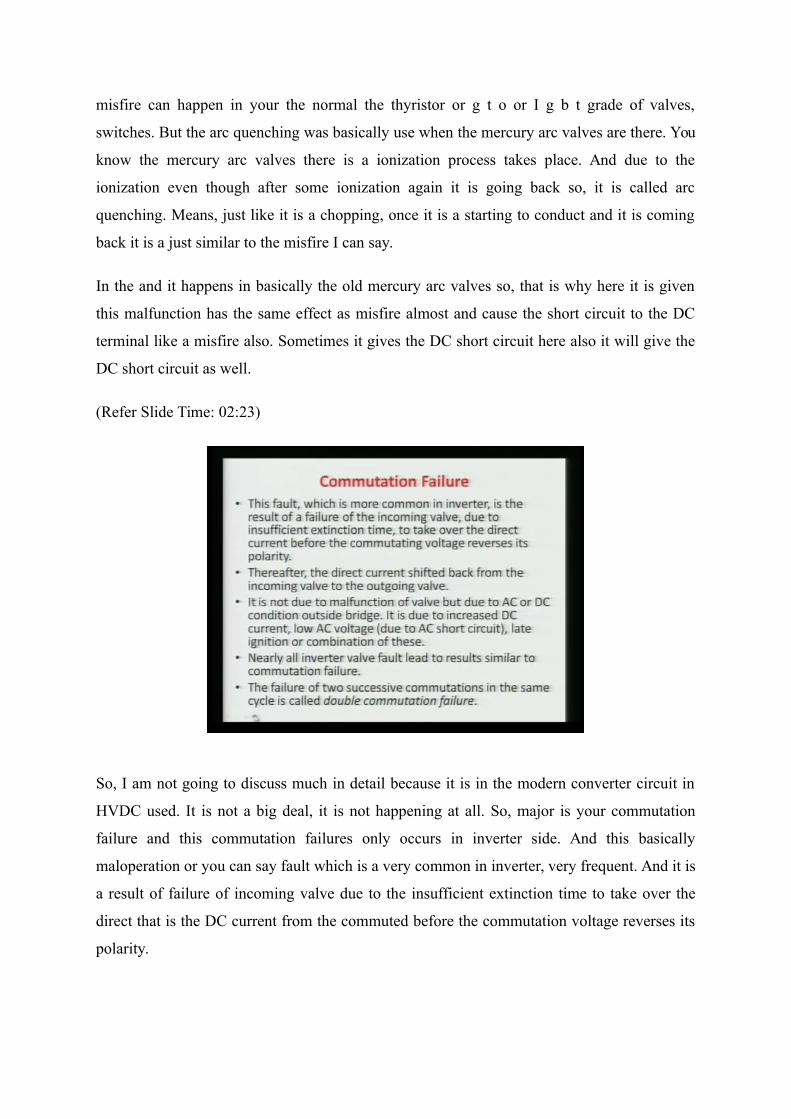
So, I am not going to discuss much in detail because it is in the modern converter circuit in
HVDC used. It is not a big deal, it is not happening at all. So, major is your commutation
failure and this commutation failures only occurs in inverter side. And this basically
maloperation or you can say fault which is a very common in inverter, very frequent. And it is
a result of failure of incoming valve due to the insufficient extinction time to take over the
direct that is the DC current from the commuted before the commutation voltage reverses its
polarity.

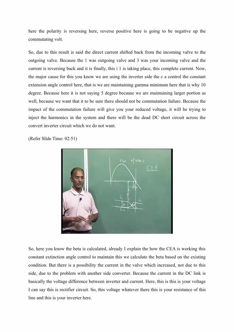
Here again if we will see I will draw the commutation voltage of valve 3 here, this is you
know if you are firing here that is your beta degree and there will be some u period. And you
know, this is a commutation voltage is reversing if your conduction start and going beyond
this at this point, you can say the voltage is going to reverse. So, what happen the valve? This
is your e b a means it is of valve three. So, here once valve 3 is going to be fired in the
inverter circuit, you know we are just delaying here. So, if it is conducting here and it is
commutation is not successful before this zero crossing. Then there is a most possibility
because the voltage is reversing and then what will happen? The current which was taken by
3 it will be going back and your previous valve that is again valve 1.
Because you know in upper bridge it is 1 3 and 5. So, 1 was conducting earlier and 3 was fire
so the commutation will be not successful, if it is a delaying much here and this is the
happening. It is not always necessary even though sometimes you have come to up this point
even, and there is also possibility the commutation failure, why? Because this rate of here the
voltage which is going down and now you can see the polarity across the valve is going to be
positive. So, this voltage is increasing and the, but current was decreasing in valve 1. Here, in
valve 3, current is increasing voltage is decreasing.
So, at this at near to the 0 crossing before that if it is not successful, then there is a possibility
of the commutation failure. Means here, I can say if you are drawing your current here now,
let us suppose this is your i 1 current which was i d here and your i 3 was here, i 3 was 0 now,
the commutation starting. Now, this will because the it is the fired voltage is the positive so,
the current will here it will be increasing and this will be here decreasing. Now, there is
possibility that here even though this is coming here and again it is coming back and this is
has taken it is coming back here again. So, especially here the near to this 0 crossing if it has
cross certainly there will be commutation failure.
But even though before also, there is a possibility because here it is the voltage is very less
across this and is a decreasing there is a possibility this current I 1 which decreasing. But
suddenly it is start increasing because the voltage across is becoming positive, very faster rate
and this is going to be negative this side. So, what happens? This the commutation was taking
place, but it was not successful. Means, we want that in actual case this should take the
complete current here and this should go 0 and we want this, and this is called the
commutation volt. So, that is why it is called the commutating voltage reverses it is polarity,
that is very well here. If it is not successful up to here in this case, it will be failed because
here the polarity is reversing here, reverse positive here is going to be negative up the
commutating volt.
So, due to this result is said the direct current shifted back from the incoming valve to the
outgoing valve. Because the 1 was outgoing valve and 3 was your incoming valve and the
current is reversing back and it is finally, this i 1 is taking place, this complete current. Now,
the major cause for this you know we are using the inverter side the c a control the constant
extension angle control here, that is we are maintaining gamma minimum here that is why 10
degree. Because here it is not saying 5 degree because we are maintaining larger portion as
well, because we want that it to be sure there should not be commutation failure. Because the
impact of the commutation failure will give you your reduced voltage, it will be trying to
inject the harmonics in the system and there will be the dead DC short circuit across the
convert inverter circuit which we do not want.
(Refer Slide Time: 02:51)
So, here you know the beta is calculated, already I explain the how the CEA is working this
constant extinction angle control to maintain this we calculate the beta based on the existing
condition. But there is a possibility the current in the valve which increased, not due to this
side, due to the problem with another side converter. Because the current in the DC link is
basically the voltage difference between inverter and current. Here, this is this is your voltage
I can say this is rectifier circuit. So, this voltage whatever there this is your resistance of this
line and this is your inverter here.

So, this current which is flowing it is basically here v d o i here v d i and here v d r. So, the
voltage difference divided by r will be the current here. So, even though there is no problem
this side, problem may this side also because the current increase. Once current is increasing,
that is possibility of this your u can be shifted. So, if you are landing this side, then
commutation failure will be there so, it is the malfunction valve due to the either AC side
problem or the DC side problem. Condition outside the bridge or it is due to the increase the
DC current as I said if the current is increased then your u will be more.
(Refer Slide Time: 07:06)
So, this is one cause and another the possibility here, the voltage at the this side and this side
has a very severly low. If voltage is low again, then your u will be more and finally, we can
go for this here. What happen the voltage is reduced at that time because in calculation of
beta we use the e m and also, we use your this current is also appearing in this. So, this beta
calculation once you are calculating and then even though happens, then we are just the
commutation failure will be there. Sometimes here, due to the late ignition of this means you
have calculated beta here exactly the same, but due to the controller, it is trying to say that
you have to delay, it 5 degree here.
You have given the pulse, the pulse generation is say delayed by 5 or 6 degree something,
then again it will be shifted this side. So, either your DC current increase either the low
voltage AC side networks or your delay in this firing angle here will lead to your
commutation failure. Or it may be combination of these even, not only individually it is the
possibility the current is also increase in the voltage is less this side, what happens? The
commutation failure may occur. So, that is why it is written late ignition or the commutation
of all these three problems may lead to your commutation failure.
So, here one sentence I have written that nearly all the inverter valve fault lead to the similar
phenomena, similar phenomena like the commutation failure. If we will see the misfire, is
also some sort of the same if we will just draw the misfire. You will find it is the almost the
phenomena is the DC dead short circuit, there is the possibility of the next valve will be not
conducting due to the negative voltage, we will see here for the commutation failure. So, it
will give you the nearly same result as other faults in the inverter circuit. So, that is why it is
it should be discussed very carefully and it is very common as well. Because always you are
calculating beta and u as keep on changing due to the system and network conditions and it
may happen.
So, failure of the two successive commutation in a same cycle, you know there is a
possibility, if so as I said here 1 and 3 commutation was unsuccessful. If it is only one
commutation failure now I can say this is one commutation. Failure is there in one cycle then
it is called single commutation failure. But there is a possibility that in the same cycle there is
a two commutation failure means, it suppose it is a 1 and 3 is failure now, after that we will
find let us suppose a 2 and 4 is failure and so on. So, forth then there is a double commutation
failure and that is the very very serious.
So, in that case what we do if it is a frequently occurring even though double commutation
failure, then we have to block the bridge or we have to bypass it. So, we will discuss the
double commutation failure as well. To understand and see what will be the output voltage?
And what will be the sequence? Now, we have to assume let us 1 and 2 are conducting and
now valve 3 is given the pulse and it is igniting, but after certain time it is going to be the
commutation between 1 and 3 was not successful. And it is you know current is not complete
and it is going back to again valve valve. Valve 1 and 1 and 2 again are conducting in the next
sequence as well.
Then we have to you know we are firing the valve after every 60 degree so, though once 3 1
and 3 was unsuccessful, then the next valve will come at the 4. We have to give the pulse to
the 4 and the 4 will conduct because the voltage across this will be positive and this will lead
to your dead short circuit. Because 1 4 in the same limb is conducting to DC short circuit is

appearing. So, it will conduct then here the as I said the 2 and 4 will be successful and only
valve 1 and 4 will be conducting now. So, it is a short circuit. Now, next sequence of the
valve will be 5, the pulse will come to this side, but this will not conduct, we will see.
Because the voltage across this will be negative, because once 1 and 4 are conducting, we
will find the voltage across this in inverter operation. The voltage across your valve 5 will be
negative even though pulse is there and it will not conduct so, what will happen? Again 1 and
4 is continuing. So, next turn will come to the 6 and we will find the 6 will conduct because 1
and 4 commutation will be successful, if then again 6 and one pattern is coming. Then after
that 1 one is coming which is already conducting so, there is no problem so, 6 1 will continue
then will 2 will come and then it is will be your 1 and 2 will be there. So, in whole cycle you
can see it is a now we got the our 1 2 pattern and finally, we are also getting 1 2 and so on so
forth. So, it is automatic clearing so, the commutation failure is a self clearing phenomenon in
the single cycle if it is a single one.
(Refer Slide Time: 13:03)
To see this, let us there is a various type of possibilities are there as same thing I said here.

(Refer Slide Time: 13:07)
Let us see, this is the I can say the voltage, to explain here this figure is basically nothing but
your line to line voltage. If we will see here as I said at the point A here, at point A I mean
before that your 6 and 1 were conducting and 2 was given pulse at the a point. And you can
see here also the commutation here this 2 is taking complete current and here 6 is going to be
0. So, the commutation between 6 and 2 is successful and then at the point b only valve 1 and
2 are conducting. And you can see this voltage here; it is the negative voltage which is
appearing here. Similarly, we can see the figure a here, it is nothing but it is the positive and
the lower side the voltage of this your DC terminal. And the second 1 is a line to line is a
difference between positive and your negative here you can say it is fed into the which is
positive. And this is your here the negative 1 the voltage is appearing.
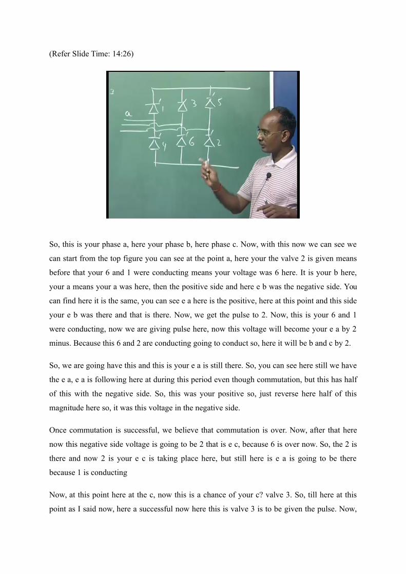
So, to see this what I can do? I can draw again our 6 pulse bridge converter circuit so, it will
more clear why the voltage will be there. This is your valve 1, here your valve 4, here your
valve 3, we are having valve 6, here we are having valve 5 and then we are having valve 2
here.
(Refer Slide Time: 14:26)
So, this is your phase a, here your phase b, here phase c. Now, with this now we can see we
can start from the top figure you can see at the point a, here your the valve 2 is given means
before that your 6 and 1 were conducting means your voltage was 6 here. It is your b here,
your a means your a was here, then the positive side and here e b was the negative side. You
can find here it is the same, you can see e a here is the positive, here at this point and this side
your e b was there and that is there. Now, we get the pulse to 2. Now, this is your 6 and 1
were conducting, now we are giving pulse here, now this voltage will become your e a by 2
minus. Because this 6 and 2 are conducting going to conduct so, here it will be b and c by 2.
So, we are going have this and this is your e a is still there. So, you can see here still we have
the e a, e a is following here at during this period even though commutation, but this has half
of this with the negative side. So, this was your positive so, just reverse here half of this
magnitude here so, it was this voltage in the negative side.
Once commutation is successful, we believe that commutation is over. Now, after that here
now this negative side voltage is going to be 2 that is e c, because 6 is over now. So, the 2 is
there and now 2 is your e c is taking place here, but still here is e a is going to be there
because 1 is conducting
Now, at this point here at the c, now this is a chance of your c? valve 3. So, till here at this
point as I said now, here a successful now here this is valve 3 is to be given the pulse. Now,
this is the case I am taking, this valve was expected to receive a gate signal at this red line,
but due to some problem there is the delay in the ignition. I am not saying it is due to the
voltage down, if voltage down also, then it will conduct here and then it will follow this one
here it will be like this half of this. But it was given here the pulse was expected, but it was
delayed by 5 degree let us suppose, what happen? Now, it is delayed slightly.
Once it is delayed here means it got the signal at the c pulse and it will conduct because you
can see the voltage across this it will be positive. How it is positive? This it is we required for
3 is the commutation voltage is e b a and e b a you can see it is your a this is a b b minus this
is positive and it will conduct. You can see at this point here it is a negative and this is still 0
so, it will be positive and it will conduct. So, it will conduct at the c point, it is believed here
that is the 5 degrees delayed.
There are so many conditions are there. It means even though it can conduct here and due to
the network condition during that after conduction may be voltage reduce and u is delayed so,
it will be continuing here. So, let us first see here we are giving the pulse here, but it is
delayed and we are giving the pulse at this. Now, if we are giving the pulse at the c point,
what will happen? It will be the you can see the current now it is going to is going to increase
in the valve 3 and 1 here it is going to decrease. Because this is your i o i 1 this is your i 3.
So, we get the pulse here, now it is going to be here. Now, you know as in the regular practice
what happens the here your at this point? This is the delayed and at this point we have to give
your, there commutation should be here should be over at this point, but it is now delaying.
And we are expecting that here current was increasing and it was not successful and this you
can say it is again it is picking it up. So, what will happen? It was even though in normal
condition, at this point the commutation should be successful by this. And then your 2 and 3
should continue, but it is not happening. So, the dotted line shows that if your there is no
commutation failure dark line is saying that there is some commutation failure.
So, what happens here? You can say if it is a continually conducting so, here your you have
given the pulse, now this will be the half of the line voltage you can say. Now, what happens
1 and 3 here? Your positive side voltage will be e c minus e c by 2 and this side your 2 is
there so, it is a e c. So, you can see here we are having e c here on the top of this and minus e
c will be this side half and half of the magnitude so, this is your this will be curve like this.
So, it is just solving here and it is now increasing and your commutation even through it is

not successful till this and now at this point here now there was turn of valve 4. You can see
here at this point e, after 60 degree.
Now, the possibilities here, the various possibilities are there is a possibility that commutation
failure between 1 and 3 is before e or even though after e. You see this point here is very
clearly, what is in this case there is a possibility here. This is a increasing and it is have taken
even the valve before that is even though your firing of the sequence firing of the valve 4, it is
a possible. And here 1 was taking here and finally, it is coming here. So, what happens before
this point e? Possibility was that your 1 and 2 is continuously conducting. Or the possibility
was that 1 2 and 3 are conducting, are you getting my point? Here what I want to tell that, this
period is very larger; this period can be lesser as well depending upon the circuit condition.
So, here in this figure it shows that here this is exceeding even though at firing instant of 4.
So, what happens? At this 4 will be getting the pulse and the sequences are the 60 degree. So,
at this e your you can say 1 2 and 3 were conducting because the commutation between 1 and
3 was even though still continuing. And 2 was earlier conducting and now 4 got the pulse so,
1 2 3 4 are conducting at this time. I will also show you, just after this another slide that let us
suppose it has occurred before, then what will be the output mentioned.
So, here the 4 got the pulse and it will conduct because the voltage across this you have to see
what is happening. When your 1 2 3 are conducting, now 1 2 3 here conducting this would be
e c by 2 minus. This is c is conducting now you can say it is your c and it is your e so, e c a
should be positive. So, e c minus e a should be positive, then only 4 will conduct otherwise it
will not conduct.
Now, see at this point e come here, now e c is this and your a is this so, positive minus
negative, negative then it will be still positive and that 4 will conduct. So, 4 will conduct now
you can see there is a 2 commutation is occurring here, another is part of the upper valve.
This still 1 and 3 commutation failure is occurring because 3 1 is taking back here the current
and 3 is going to here 2 and 4 are also getting there. And now what happens? In this period,
the 2 and 4 you can see once this happens, the commutation is here is over in between even
though u. And this is taking your normal u period of the commutation here and then here now
you can say at the G point.
Your here it is a 4 and upper 1 is 1 and this is basically nothing but your dead short circuit
here because 1 and 4 are conducting means you are having the DC short circuit. There is a
one condition as I said there is a conduction of 1 2 3 and 4. Here, and 1 and 3 here the
commutation failure occurs, even though the 2 4 commutation is going to take place. Means,
you can see here at this figure, this is here this commutation between 2 and 4 is this period u,
but this is a 1 and 3 here, this period is at before that. So, in this section what happens? It is 1
2 and 4 are there conducting at a time. So, that is why corresponding to this you can see what
is the voltage in this period.
Now, we have to just see here, if you have this 4 is going to fire and there is a voltage 1 2 3
and 4 are conducting, what will be the output voltage? Means at the point e, I want to see
what is the positive, no doubt the line to line voltage will be 0. The different between the
positive and negative will be 0 because there is a dead short circuit. But here since the these
are conducting here, these are conducting here so, the voltages here will be the different.
Here, once 1 and 3 is conducting it is of course, minus e c by 2, here 2 and 4 are conducting it
is a minus e b by 2 will be there. And you can see here at this point, here at this point your
this will be the this is a minus e c by 2 and this is going to be here suddenly this is a both will
be equal.
If both is not equal, then it would be not 0. Because this whatever this is going to
commutation takes place here, it is a minus e b by 2 this will be also e b by 2 because this is a
dead short circuit which is appearing here. So, both positive and negative should be same,
then otherwise the difference is 0 because this is dead short circuit here. So, here you can say
both are here and during this 1 2 4 here, this is going to be 0. Now, once the here it is going to
be 0, during this period when commutation between 1 and 3 is unsuccessful. And now one
got the complete current, now lower one still it is continue 2 and 4 is there, now you can see
what is your positive and what is your negative voltage.
Now, this one and here this is your this is still continuing so, this your minus e by e b by 2 it
will be there. And this is a same polarity will be there in this side because this is conducting
so, this voltage will be there. So, both if this pulse will be nothing but your minus e b by 2
here. Once the commutation is over, then 1 and 4 are conducting means, your both side it is
your voltage e a will be there. Once this is conducting here if the e a, this is conducting here
is e a when this no two valves are conducting in the bridge. So, both are following e a, means
e a minus e a will be 0 and you can see here the output voltage is going to be 0 here and it is
going to follow here. Now, at this point H here, now it is the turn of valve 5 at this point H
because every 60 degree here, 60, this 60, every 60 we are giving the pulse the 5 will be
given the pulse at this point.
Once 1 and 4 are conducting here, the this will be your c and it is your e a so, e c a must be
positive then only 5 will conduct. Now, you see whether it is at this point, what is the voltage.
Now, where is the c? This is your condition, your c is this, c minus this. So, more positive is
negative, then c so it will be negative voltage, from line to line also we can say. So, it will not
conduct at all so, what will happen? Now, it will again continue and you can say this follow
the same, voltage will be 0 and now this is a turn off your valve 6. Because after this, sixty
degree we are giving the pulse to 6 and you will see the lower here there is a commutation
because the voltage across 6 will be the positive. How come? You can see here this is e a is
here and it is a b so, e a b should be positive. So, you can see e a minus e b. Here, e a now
this is your e b and this will be positive.
It is positive minus minus negative so, it is positive and it will conduct and you can see there
is a commutation is happening between 4 and 6 and it will be successful. Now, at this point
your again one is conducting and here the 6 is conducting. Now, at this point L, now the turn
off it is valve 1, after 6 1 2 again and 1 is already conducting so, it will conduct. So, it is
again continuing, this 6 is also continuing. Now, this is the at this point M now this is turn off
2. And 2 here what happens? It will be if commutation is there so, 6 and 2 will be successful
and then we are going to have 1 and 2 conduction and we find now this regular pattern is
arising, you can 1 2 here again we are here.
So, during this period only something happens, sometimes you can say the voltage is 0. Here,
some positive voltages are also appearing across your inverter instantaneous voltage, but
average will be no doubt negative. And the voltage will be reduced and it will introduce a lot
of harmonics in the system. With the DC harmonics as well as the current also you can say
current is not as per our required practice in the phases a b c. so, that will also introduce lot of
harmonics to the AC side as well as the DC side of course, it will give the harmonics.
So, this is the case when we assume that this is a going to exceed this value. Means, either 4
and we said it is still this commutation was occurring between here and it was exceeding
when the before this after your firing instant of 5. Now, let us take the case when this was
over commutation was failed before the 4, then your voltage will be something different and
it will be not in this case. So, in this case let us see the again we can now draw because that

picture was very complex and it was not clear. Now, here I am going to draw and you see
how it is going to happen.
Now, as our initial condition here this I am taking as e b a is the commutation voltage of
valve 3. Then I have to write a line to line voltages, here I have to write it is a e c b, here it is
e a c and here again I have to write e b a. Because and here it is a b here it will be reverse of
this, it is e b c here it will be e c a and this will be your e b c. I am drawing the line to line
voltage, Ok. Now, you can see this is the commutation voltage of your this e b a is your
commutation voltage and now this will be I am taking the condition of the valve 3 should be
fired. Because this is your 0 axis here and this is your beta degree and I am taking this is
equal to your 30 degree. Because this is a sixty degree, this point here this is your sixty here,
this is 60 so, it is complete 180 degree.
So, 30 degree I am assuming and you know then what was your previous case here? Your
valve 2 timing will be this, valve 1 will be this and here your valve 4 will be this. Just we
have to write the your order here 5 here your 6, here again it is 1 and here your 2 is again. So,
these are the valve conduction means the pattern gate pattern which is given to all the valves
after sixty degree. So, we can draw this suppose 1 is here being fired means before that your
6 and 5 and 6 were conducting during this period, here the there will be some commutation
between this period and I can say here 6 and 1 will be conducting. And between this period
your 5 6 and 1 will be conducting. Ok? So, once your 5 and 6 were conducting, what will be
the output voltage here?
I am talking about this minus this so, 5 and 6 here it is a c, here it is a b so, it is e c b should
be the voltage, and see where is the e c b? e c b this is your e c b here so, means this was your
see this is e c b here so, this is your e c b was there and now I gave the pulse to 1 5 6 1 are
conducting, means the commutation here will takes place. So, this voltage here will be minus
e b by 2 and here it was e b so, 1. 5 e b by 2 minus it will be there. Because this minus here
this 6 is conducting so it is a e b here minus means 0.5 e b so, it will be minus 1.5 e b. Yeah,
3 by 2 it is 1.5 e b only. Now, what will this will be? This will be just it will be here as if you
will see it will be somewhere here so, what happens here? It will be here the commutation
and then your commutation is over now, your 1 and 2 are conducting means here it is e a and
here it is 1 and 6 sorry. So, it will be b and here 1, so a and b will be there and a b is where?
Here, this is a b so, it will be coming here and then it will be coming up to here at this point.

Ok? Because this is you can say this is a voltage e a b is there so, just how I draw here I just
check here, e a b here, this is going to be also it will follow e a b.
Now, at now that point 2, now you are giving the pulse 2, here gate 2 valve 2 and now there
will be commutation between 6 and 2 will happen. And we will find the sequence now, you
can see from here, the voltage you will find the voltage here will be again like this, it will be
here it is going something here. And then again the voltage will be like this means, at this
point here during this your 1 and 2 are conducting. Means, it will be once 1 and 2 are
conducting you can see 1 is your e a here e c a a minus c so, e a c will be the voltage here, it
will be coming. Now, here as 3 as part of previous case, now here we are giving the pulse to 3
here I am not delaying now. I am giving the pulse and it is conducting, but due to the some
problem here network side, the commutation is going to be longer and we will be see what
happens.
Now, once here 3 is given pulse now, your the voltage here between now 1 and 3 now it will
be your voltage will come here like this. Now, what happens? I am telling that is the here is
going to be this and before 4, before the 4 is going to ignite now this 3 is going to be off.
Means, during this period your 1 2 3 are conducting. Now, at this point now 3 is off as
because the current here took place see the means here your this is your 1 now, going to be
here the current and this was took this was taken care and finally it is going to be 0. And
before this it is commutation is valid. So, now at this point here I am assuming now here your
again 1 and 2 are conducting because 3 is off. It took the some current and went back it was
off because the polarity was reversing.
Now, polarity was not reversing, but due to the decrease it was off and 1 is 2 is taking
complete current and it will be certainly it will off after this. Now, here 1 and 2 is conducting,
then what will be the voltage again? e a c. e a c is here, it will be coming here and this will be
your voltage. Ok? Now, your 4 is given a pulse and it will be the positive you can see, the
voltage across this is a positive and it will conduct. So, at this point here this is a sequence of
valve 4 and it will be given pulse and it will be conducting. So, now your valve 1 2 4 are
conducting, means 1 2 and 4 means this is here the dead short circuit and this is DC voltage
will be 0 means we are going to have here the certain voltage here at 0.
Now, here at this point, there will be some here period where 1 2 and 4 will be conducting
means there will be commutation between 2 and 4 and it will be successful. And then later on

what happens your 1 and 4 are conducting now starting from here. So, till 1 and 4 are
conducting now, the DC output voltage will be 0 and now we have to come at the 0.5 where
the valve 5 was expecting a gate pulse. Now, we are giving the gate pulse it is similar to the
previous case and you will find this it is the voltage across this is not positive. You can also
check from here, this once your 1 and 4 are conducting. Here is a c so, e c a should be
positive, but e c a is not positive because e c a you can see here, your e c a is this one, this is
your e c a. And you can say this is negative, it will not conduct.
So, what will happen now? This will be not conduct at all and now we are again going to
have 1 and 4 conduction till 6. So, your output voltage here line to line will come here up to
this. Now, the 6 is getting command, 6 is getting here and there is a commutation here
between your 1 4 6 means 4 and 6 will be commutation and it will be successful. So, once
there is 1 4 6 now here 1 and 4 till their output voltage here will be the 0. So, in this case also
here it will be up to this point it will be 0. Now, here I can say this is here now your 6 and 1
are conducting now, your voltage will follow, we will see e a b because 1 and 6 here, a and b
we have to see e a b. And your e a b is very near to here and it will follow here and it will go
up to one.
(Refer Slide Time: 29:58)
Now, 6 1 is conducting and you are giving gate pulse to 1 it will be still conducting so, it will
continue. So, it will come here up to here now this is turn of 2. Now, once you are giving a
pulse here now there is a commutation between 6 1 2 it means 6 2 commutation is there and it
will be now taking place as usual here and now this voltage will repeat. So, now we have
come back here, you can say now we are here. So, this is a complete cycle and now this is
your output voltage here will be change here compared to the previous one. Yeah, At that
time it was directly DC here because we are coming outside here. Similarly, in this case now
you can is very careful suppose it is ask to draw the valve voltage across any so, this side you
should be very careful what will be the valve.
It is I can say let us draw the valve here 5 then you have to see where it is going what will be
the voltage here what is not. And that will be not a symmetric pattern of course, here you can
say during this period once commutation failure is happening we are getting not a
symmetrical pattern. So, valve voltages also will be the different so, you can draw similarly,
this is the DC output voltage. It can be asked what is your valve voltage? Just it will be
coming somewhere here on this place and then you can draw. So, the procedure is same you
should be very careful just every this commutation period as well as non commutation period
you have to find the voltage and then you have to trace the figures.
(Refer Slide Time: 40:51)
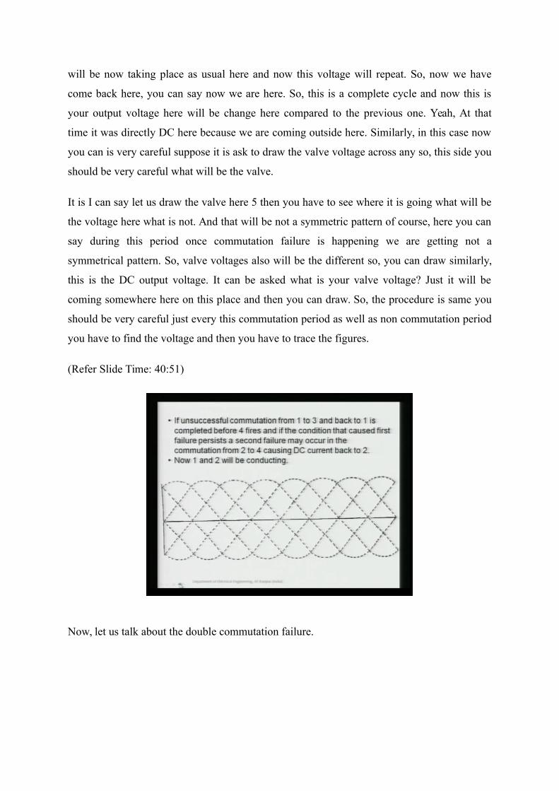
Now, let us talk about the double commutation failure.
(Refer Slide Time: 40:52)
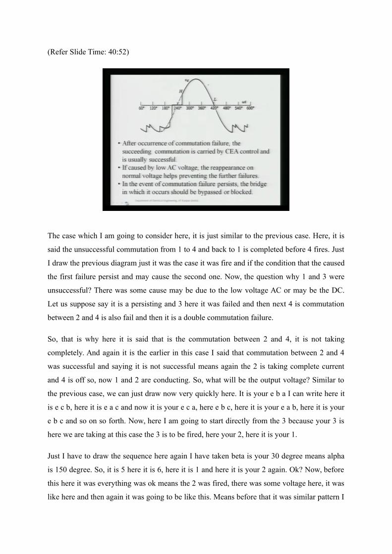
The case which I am going to consider here, it is just similar to the previous case. Here, it is
said the unsuccessful commutation from 1 to 4 and back to 1 is completed before 4 fires. Just
I draw the previous diagram just it was the case it was fire and if the condition that the caused
the first failure persist and may cause the second one. Now, the question why 1 and 3 were
unsuccessful? There was some cause may be due to the low voltage AC or may be the DC.
Let us suppose say it is a persisting and 3 here it was failed and then next 4 is commutation
between 2 and 4 is also fail and then it is a double commutation failure.
So, that is why here it is said that is the commutation between 2 and 4, it is not taking
completely. And again it is the earlier in this case I said that commutation between 2 and 4
was successful and saying it is not successful means again the 2 is taking complete current
and 4 is off so, now 1 and 2 are conducting. So, what will be the output voltage? Similar to
the previous case, we can just draw now very quickly here. It is your e b a I can write here it
is e c b, here it is e a c and now it is your e c a, here e b c, here it is your e a b, here it is your
e b c and so on so forth. Now, here I am going to start directly from the 3 because your 3 is
here we are taking at this case the 3 is to be fired, here your 2, here it is your 1.
Just I have to draw the sequence here again I have taken beta is your 30 degree means alpha
is 150 degree. So, it is 5 here it is 6, here it is 1 and here it is your 2 again. Ok? Now, before
this here it was everything was ok means the 2 was fired, there was some voltage here, it was
like here and then again it was going to be like this. Means before that it was similar pattern I
can say it was here, then it was like this and this was the output voltage. Means your
sequence was there between here I can say your 6 1 was conducting here, here 6 1 2 then here
1 2 sorry, 1 and 2 then here we are getting pulse to 3.
So, the similar here case you are giving this, your the voltage 1 and 3 commutation is taking
place and now it will be going like this. Ok? Now, before this here as the condition is before
that the commutation is failed and your at this point again here in this condition your 1 2 3
are conducting during this period. During this period, your 1 and 2 are conducting because 3
took the current, but it went back it is off and now 1 2 is are conducting. So, 1 and 2 are
conducting, your voltage will be e AC and it will follow here this portion till here is a similar
to just what I draw in the previous case. Now, the 4 here we gave the pulse and now the
commutation between here the period is 1 2 and 4 means the commutation between 1 and 4, 2
and 4 was taking place and again it was not successful.
But mind it here if this 1 and 4 are there, your output voltage is going to be 0 here. Ok? And
what happens here during this period some u degree, the commutation was unsuccessful and
then finally, it is again at this point 1 and 2 are conducting, then what will happen? Again it
will follow, e a c it will follow of course, yeah 1 and 2 is conducting. So, it will be always 1
and c is here because this was taking place, but it is not successful and finally, here this is it is
off. Now, e a c will be there of course, and e a c we have to see where is the voltage again it
depends, it is coming here or it is taking more time means it depends how much u is taking. If
it is u is here then it will follow here, if it coming here then it will go here.
So, and then it will be here, it will be going up to this point. We are assuming that is it is
taking the longer time if it is coming as I said here how much degree it is commutation failure
period is there. If it is before then it will come here and then it will follow this e c it is no
doubt about it. Now, this is going to here and now we are going to fire the 5. Now, once 1 and
2 are conducting you can see 5 is still negative. See, 1 is conducting here and 2 is conducting
means we will see e c a, e c a is negative, where is the e c a? You can say it is a positive AC
so, it will be negative it will not conduct. And once it will not conduct then it will continue
till the turn of 6. Its ok?
Now, let us see the valve voltage 6. 1 and 2 are conducting, here it is c so, it is c b we
required the e c b should be positive so, e c b where e c b? e c b here the b c is positive so,
here it is your e c b is negative, it will not conduct. So, still we have to go further and then we
are reached here. Ok?
(Refer Slide Time: 42:15)
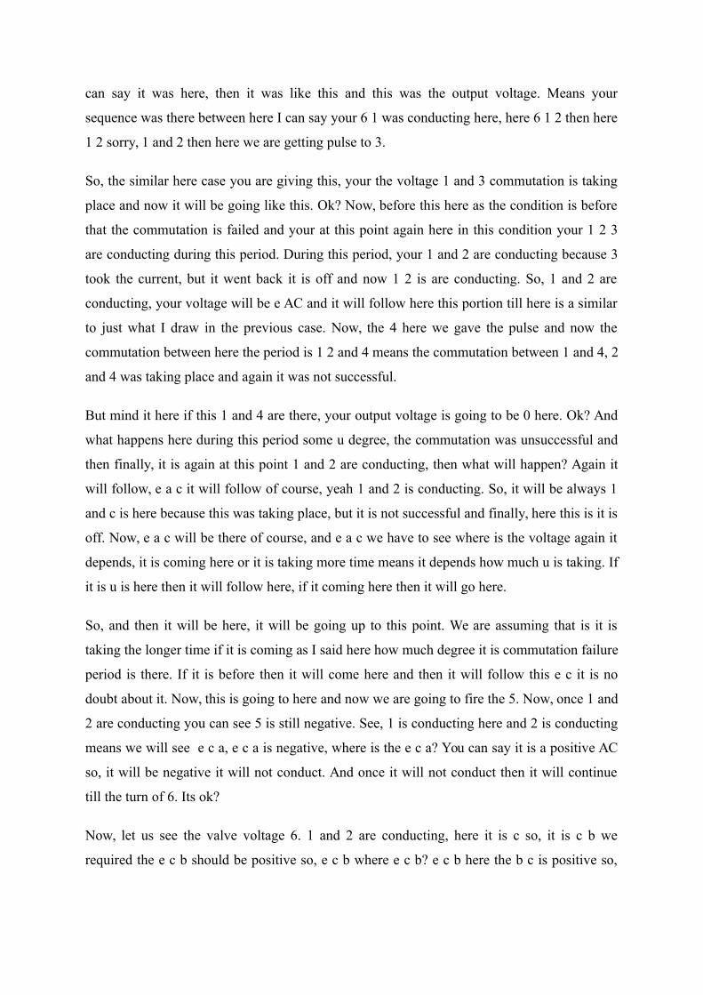
Now, you are getting gate pulse to 1 and it is conducting so. It will continue to conduct so. It
will further move. Now, we have reached here now still 2 is conducting and we are giving
pulse it will continue it so it will come here. And then the third will come and if there is no
commutation failure there is a commutation between 1 and 3 will be there and it will be
coming back here similar to this point, we are here basically. This curve from the 2 onwards
we are here basically you can see. So, it is here at this point, this curve is similar to this and
then if commutation is not failing, then we will have the sequence pattern like these voltages
and we are having.
Now, you can see here the scenario is totally different than the previous in the double
commutation failure. In once cycle is 2 commutation failures is occurred, this is a very very
severe condition of the inverter and then it should be very properly it should be monitored.
So, thats why here I have written the event of the this figure basically similar to what I draw.
Because it was not very clear now you can see we are getting the similar pattern, here our this
voltage you can see this is your 3 and 1 commutation here failure. Then it was before that 4
was fired here the commutation was unsuccessful here between this your 1 and 2 were
conducting, then here 4 was given pulse, it was suddenly short circuit. Here, 5 we tried to, no
if the commutation was over between yeah fail again 2 and 4.
Then the voltage came here, then we find here 5 it was uncertain because it is a negative
voltage, then we give 6 negative voltage then we give 1 already it was conducting, then we
give 2 it was already commutating here again we are coming 3 and it is continuing. So, here
you can say in 1 cycle now the almost the average voltage is going to be 0 rather than
negative and that is a very severe case. So, that is why it is written in the event of
commutation failure persist, then the bridge in which it is occurring why I am talking the
bridge because there may be the series of bridges for the same to lift the voltage.
So, if any of the bridge it is persisting continuously, it should be blocked or should be
bypassed. Otherwise, it is creating lot of problem in your controller as well because current is
changing very haphazardly, also the voltage is going to change your controller keep on
working. And that is it is you know controller may not be able to find the optimal solution
and general consequences may occur so, that is why here you can say this is it. So, you can
say the these are the conditions if it is persisting, it should be bypassed. But there is a
possibility now the question if the commutation failure is occurring due to the low voltage
AC here.
So, of course, there is a problem this here the low voltage here as I can say this was the
unsuccessful, next will be also unsuccessful. That is very much guaranteed because if this
voltage is less so there is also u will be larger and you are this controller. So, it may make
cause so, but if it is a voltage is coming to normal then it may not be commutation failure.
But if it is a continuously low voltage, then we have to act our VD COL so, that we can go
for the reduction of the voltage and we can operate accordingly.
So, that is why here the c a control basically try to control the here if this is unsuccessful
here, we have to take care of in the c a control so that we have to fire in advance not to
delayed it to avoid. So, these are the basically measures and cures of basically I can say the
commutation failure. So, in this we just analyze as I said the different scenarios are possible
for the commutation failure. How much time after the commutation duration is occurring?
That is the major concern it can go for the longer period, it can go for low lesser period, all
this depends upon your the AC side condition, your DC side conditions and based on that the
commutation failure is there.
So, in inverter circuit this is a very common and very persistent phenomena and if it is a 1
commutation fail is occurring in 1 cycle and it is over hardly matter. But it should not be the

continuously occurring otherwise the even though your bridges are going to be highly
stressed. The voltage across that it is all going to be very sudden changes here and there so it
should be properly taken care. So, that is why if it double commutation failure is occurring
means there is some problem in maybe bridge also and then it should be blocked and
bypassed properly.
So, this ends your commutation failure and that is why I explained very clearly that is the
commutation failure must be understood very properly because it is a very common
phenomena. And here there is no protection scheme for this commutation failure because it is
a self clearing. But if it is a persisting continuously, then we have to take care and we have to
bypass or block the bridge. So, with this I should close this and in the next lecture, lecture
number 3 we will discuss about the protection schemes, may be we used the differential
protection, we will see over voltage protection, all the protection now we have to discuss in
the combined way. Just we have to safeguard our converter on HVDC lines so, in the next
lecture number 3 we will discuss the protection schemes for this HV DC link. Thank you.
Keywords: HVDC System Faults and Protections, arc quenching, misfire, extinction time,
commutation voltage, Constant Extinction Angle (CEA) control, commutation failure,
commutation period.