
High-Voltage Connector Systems - Rosenberger Rosenberger Automotive – a Synonym for Quality and...
60
High-Voltage Connector Systems AUTOMOTIVE
Transcript of High-Voltage Connector Systems - Rosenberger Rosenberger Automotive – a Synonym for Quality and...

High-Voltage Connector Systems
AUTOMOTIVE

2
Rosenberger Automotive –
a Synonym for Quality and Innovation
On the following pages we present the high-quality Rosenberger high-voltage
connector systems developed in our automotive business area. They fulfill the tough
requirements of the automotive industry.
3Rosenberger Hochfrequenztechnik GmbH & Co. KG | www.rosenberger.com
The Rosenberger online catalog
contains the current Rosenberger
high-voltage connector systems
product range with specific
details, including data sheets,
assembly instructions, and panel
piercings.
www.rosenberger.com/ok/hv
Rosenberger Global Network 4
Quality & Environment 6
Competencies & Technology 8
Research & Development 10
Rosenberger Automotive 12
Rosenberger High-Voltage Product Overview 14
HV Contact Systems and Connection Technologies 16
Rosenberger High-Voltage Connector Matrix 18
Rosenberger Number Code 19
HVR®50 22
HVR®200 26
HVR®260 30
HVR®300 32
HVR®420 36
HPK 40
DCS 46
HV Fuse 50
HV Components 52
LVR®120 54
Contents
4
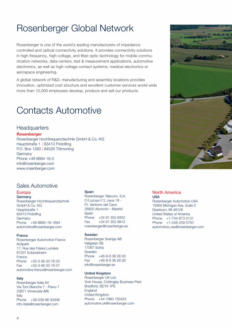
Rosenberger Global Network
Rosenberger is one of the world`s leading manufacturers of impedance
controlled and optical connectivity solutions. It provides connectivity solutions
in high-frequency, high-voltage, and fiber-optic technology for mobile commu-
nication networks, data centers, test & measurement applications, automotive
electronics, as well as high-voltage contact systems, medical electronics or
aerospace engineering.
A global network of R&D, manufacturing and assembly locations provides
innovation, optimized cost structure and excellent customer services world-wide
more than 10,000 employees develop, produce and sell our products.
Contacts Automotive
Headquarters
Rosenberger Hochfrequenztechnik GmbH & Co. KG
Hauptstraße 1 | 83413 Fridolfi ng
P.O. Box 1260 | 84526 Tittmoning
Germany
Phone +49 8684 18-0
www.rosenberger.com
Sales AutomotiveEuropeGermany
Rosenberger Hochfrequenztechnik
GmbH & Co. KG
Hauptstraße 1
83413 Fridolfi ng
Germany
Phone +49-8684-18-1694
France
Rosenberger Automotive France
Actipark
17, Rue des Frères Lumière
67201 Eckbolsheim
France
Phone +33-3-90 20 76 03
Fax +33-3-90 20 76 01
Italy
Rosenberger Italia Srl
Via Torri Bianche 7 - Piano 7
20871 Vimercate (MI)
Italy
Phone +39-039-96 30306
Spain
Rosenberger Telecom, S.A.
C/Lozoya n°2, nave 18 -
P.l. Ventorro del Cano
28925 Alcorcón - Madrid
Spain
Phone +34 91 352 8352
Fax +34 91 352 9813
Sweden
Rosenberger Sverige AB
Vallgatan 5B
17067 Solna
Sweden
Phone +46-8-6 36 26 00
Fax +46-8-6 36 26 26
United Kingdom
Rosenberger UK Ltd.
York House, Cottingley Business Park
Bradford, BD16 1PE
England
United Kingdom
Phone +44-7980 730423
North AmericaUSA
Rosenberger Automotive USA
15900 Michigan Ave, Suite 5
Dearborn, MI 48126
United States of America
Phone +1-734-673 4131
Phone +1-248-259 5750
5Rosenberger Hochfrequenztechnik GmbH & Co. KG | www.rosenberger.com
South AmericaBrazil
Rosenberger Domex Telecom Ltda.
Cabletech Avenue, 601
Guamirim
CEP 12295-230
BR-Cacapava - São Paulo
Brazil
Phone +55-12-3221 8500
Fax +55-12-3221 8543
Chile
Rosenberger Sudamérica Ltda.
Aldunate 1961,
Santiago 836-1195
Chile
Phone +56-2-3 67 11 70
Fax +56-2-3 67 12 78
AsiaChina, Asia, Australia
Rosenberger
Asia Pacifi c Electronic Co., Ltd.
No. 3, Anxiang Road, Block B
Tianzhu Airport Industrial Zone
Beijing 101300
PR China
Phone +86-10-80 48 19 95
Fax +86-10-80 48 24 38
Japan
Rosenberger Automotive Japan, LLC.
Sanno Mori Building 2-10-1 Nagata-Cho,
Chiyoda-Ku
100-0014 Tokyo
Japan
Phone +813 5511 2525
Korea
Rosenberger Automotive Korea
#307/104, Gwang-Gyo Eduhiem, 904-1,
Iui-Dong, Yeong Tong-gu
Suwon-si Gyeonggi-do (441-813)
Korea
Phone +82 70 7779 2236
Mobile +82 10 4729 6194
India
Rosenberger Electronic Co. (India) Pvt
Limited
Plot No. 263, Sector 6
IMT Manesar, Gurgaon
Haryana-122050
India
Phone +91-124-477 55 00
Fax +91-124-477 55 01
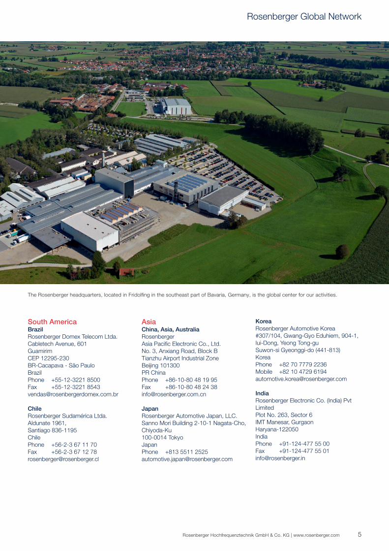
The Rosenberger headquarters, located in Fridolfi ng in the southeast part of Bavaria, Germany, is the global center for our activities.
Rosenberger Global Network
6
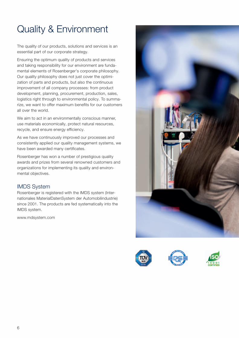
Quality & Environment
The quality of our products, solutions and services is an
essential part of our corporate strategy.
Ensuring the optimum quality of products and services
and taking responsibility for our environment are funda-
mental elements of Rosenberger's corporate philosophy.
Our quality philosophy does not just cover the optimi-
zation of parts and products, but also the continuous
improvement of all company processes: from product
development, planning, procurement, production, sales,
logistics right through to environmental policy. To summa-
rize, we want to offer maximum benefits for our customers
all over the world.
We aim to act in an environmentally conscious manner,
use materials economically, protect natural resources,
recycle, and ensure energy efficiency.
As we have continuously improved our processes and
consistently applied our quality management systems, we
have been awarded many certificates.
Rosenberger has won a number of prestigious quality
awards and prizes from several renowned customers and
organizations for implementing its quality and environ-
mental objectives.
IMDS SystemRosenberger is registered with the IMDS system (Inter-
nationales MaterialDatenSystem der Automobilindustrie)
since 2001. The products are fed systematically into the
IMDS system.
www.mdsystem.com
7Rosenberger Hochfrequenztechnik GmbH & Co. KG | www.rosenberger.com
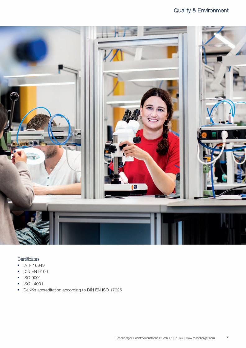
Certificates ■ IATF 16949
■ DIN EN 9100
■ ISO 9001
■ ISO 14001
■ DaKKs accreditation according to DIN EN ISO 17025
Quality & Environment

8
Competencies & Technology
Rosenberger's mission is to be a leader when it comes to innovation and technology within its business
segments.
The ongoing focus on cost management and process optimization complements our commitment to the in-
creasingly stringent requirements for delivering products of the highest quality. Effective research & development,
the very latest manufacturing technologies, the highest possible levels of efficiency in production processes, and
continuous improvement of process automation make up Rosenberger`s core competencies.
9Rosenberger Hochfrequenztechnik GmbH & Co. KG | www.rosenberger.com
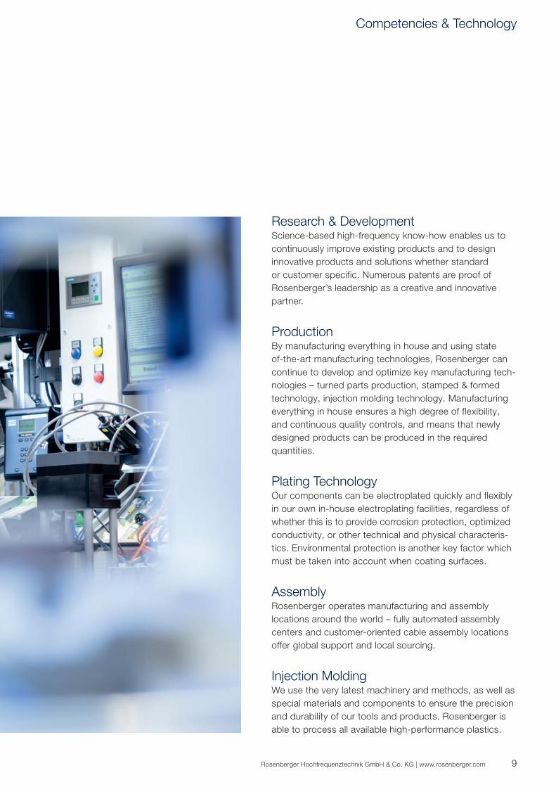
Research & DevelopmentScience-based high-frequency know-how enables us to
continuously improve existing products and to design
innovative products and solutions whether standard
or customer specific. Numerous patents are proof of
Rosenberger’s leadership as a creative and innovative
partner.
ProductionBy manufacturing everything in house and using state
of-the-art manufacturing technologies, Rosenberger can
continue to develop and optimize key manufacturing tech-
nologies – turned parts production, stamped & formed
technology, injection molding technology. Manufacturing
everything in house ensures a high degree of flexibility,
and continuous quality controls, and means that newly
designed products can be produced in the required
quantities.
Plating TechnologyOur components can be electroplated quickly and flexibly
in our own in-house electroplating facilities, regardless of
whether this is to provide corrosion protection, optimized
conductivity, or other technical and physical characteris-
tics. Environmental protection is another key factor which
must be taken into account when coating surfaces.
AssemblyRosenberger operates manufacturing and assembly
locations around the world – fully automated assembly
centers and customer-oriented cable assembly locations
offer global support and local sourcing.
Injection MoldingWe use the very latest machinery and methods, as well as
special materials and components to ensure the precision
and durability of our tools and products. Rosenberger is
able to process all available high-performance plastics.
Competencies & Technology
10
EMCThanks to many years of close cooperation with automobile manufacturers in the supply of components, Rosen-
berger plays a major role in the EMC development process and is very familiar with the procedures for EMC tests
on vehicles. In addition to this, Rosenberger has its own in-house EMC laboratory and associated measure-
ment equipment, enabling it to conduct tests alongside development at sub-system level in relation to radiated
emissions compliant with CISPR 25 and immunity to conducted disturbances, for example in accordance with
ISO 11452-4 (BCI method) or ISO 11452-5 (stripline method). At component level, Rosenberger is working with
Bedea as a supplier of measurement equipment for triaxial shielding measurement technology compliant with
IEC 62153-4-x, and is also one of the driving forces behind the standardization of optimized and innovative
measurement procedures and standards for high-voltage products. On request, we are happy to assist our
customers in deriving and defining product requirements at component level.
In order to optimize the EMC behavior of HV connectors, 3D field simulation and measurement of shielding
properties (feeder wire/triax method) are used as standard and therefore form an integral part of the development
process.
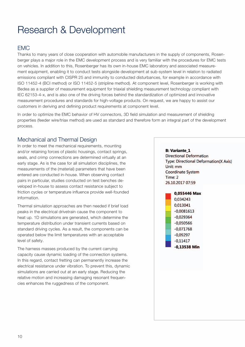
Mechanical and Thermal DesignIn order to meet the mechanical requirements, mounting
and/or retaining forces of plastic housings, contact springs,
seals, and crimp connections are determined virtually at an
early stage. As is the case for all simulation disciplines, the
measurements of the (material) parameters that have been
entered are conducted in-house. When observing contact
pairs in particular, studies conducted on test benches de-
veloped in-house to assess contact resistance subject to
friction cycles or temperature influence provide well-founded
information.
Thermal simulation approaches are then needed if brief load
peaks in the electrical drivetrain cause the component to
heat up. 1D simulations are generated, which determine the
temperature distribution under transient currents based on
standard driving cycles. As a result, the components can be
operated below the limit temperatures with an acceptable
level of safety.
The harness masses produced by the current carrying
capacity cause dynamic loading of the connection systems.
In this regard, contact fretting can permanently increase the
electrical resistance under vibration. To prevent this, dynamic
simulations are carried out at an early stage. Reducing the
relative motion and increasing damaging resonant frequen-
cies enhances the ruggedness of the component.
Research & Development
11Rosenberger Hochfrequenztechnik GmbH & Co. KG | www.rosenberger.com
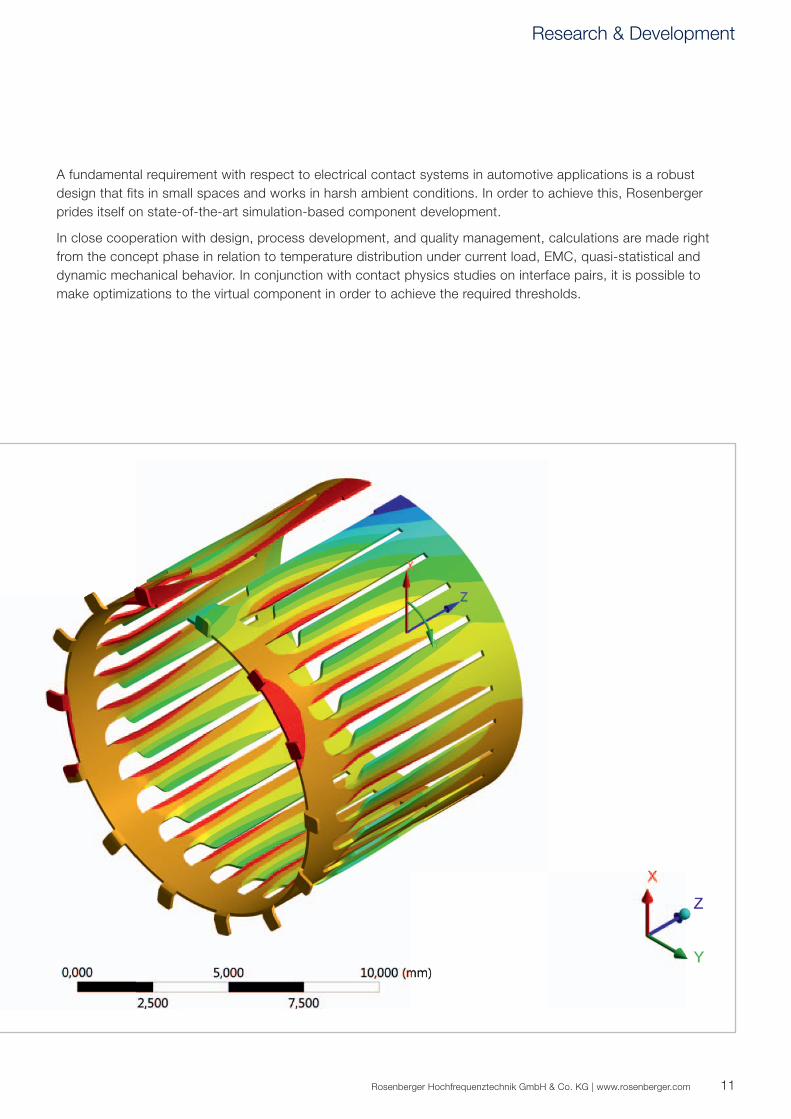
A fundamental requirement with respect to electrical contact systems in automotive applications is a robust
design that fits in small spaces and works in harsh ambient conditions. In order to achieve this, Rosenberger
prides itself on state-of-the-art simulation-based component development.
In close cooperation with design, process development, and quality management, calculations are made right
from the concept phase in relation to temperature distribution under current load, EMC, quasi-statistical and
dynamic mechanical behavior. In conjunction with contact physics studies on interface pairs, it is possible to
make optimizations to the virtual component in order to achieve the required thresholds.
Research & Development
12
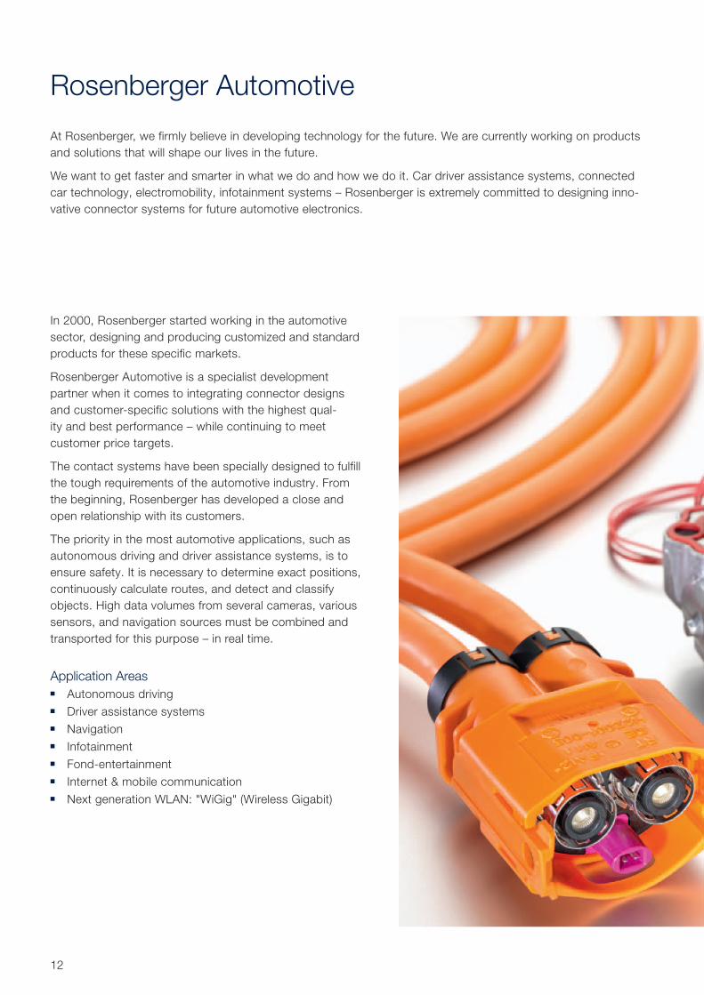
Rosenberger Automotive
At Rosenberger, we firmly believe in developing technology for the future. We are currently working on products
and solutions that will shape our lives in the future.
We want to get faster and smarter in what we do and how we do it. Car driver assistance systems, connected
car technology, electromobility, infotainment systems – Rosenberger is extremely committed to designing inno-
vative connector systems for future automotive electronics.
In 2000, Rosenberger started working in the automotive
sector, designing and producing customized and standard
products for these specific markets.
Rosenberger Automotive is a specialist development
partner when it comes to integrating connector designs
and customer-specific solutions with the highest qual-
ity and best performance – while continuing to meet
customer price targets.
The contact systems have been specially designed to fulfill
the tough requirements of the automotive industry. From
the beginning, Rosenberger has developed a close and
open relationship with its customers.
The priority in the most automotive applications, such as
autonomous driving and driver assistance systems, is to
ensure safety. It is necessary to determine exact positions,
continuously calculate routes, and detect and classify
objects. High data volumes from several cameras, various
sensors, and navigation sources must be combined and
transported for this purpose – in real time.
Application Areas ■ Autonomous driving
■ Driver assistance systems
■ Navigation
■ Infotainment
■ Fond-entertainment
■ Internet & mobile communication
■ Next generation WLAN: "WiGig" (Wireless Gigabit)
13Rosenberger Hochfrequenztechnik GmbH & Co. KG | www.rosenberger.com
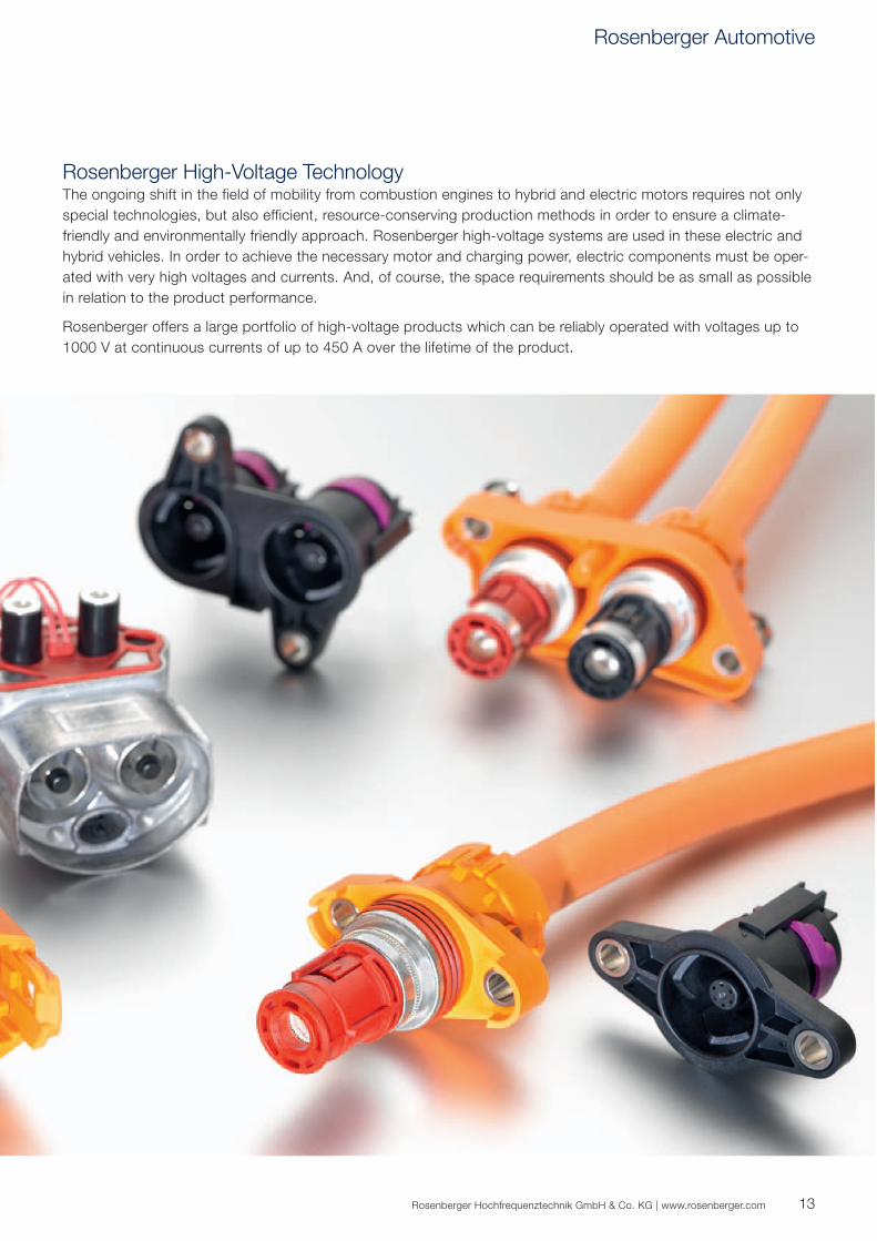
Rosenberger High-Voltage Technology The ongoing shift in the field of mobility from combustion engines to hybrid and electric motors requires not only
special technologies, but also efficient, resource-conserving production methods in order to ensure a climate-
friendly and environmentally friendly approach. Rosenberger high-voltage systems are used in these electric and
hybrid vehicles. In order to achieve the necessary motor and charging power, electric components must be oper-
ated with very high voltages and currents. And, of course, the space requirements should be as small as possible
in relation to the product performance.
Rosenberger offers a large portfolio of high-voltage products which can be reliably operated with voltages up to
1000 V at continuous currents of up to 450 A over the lifetime of the product.
Rosenberger Automotive
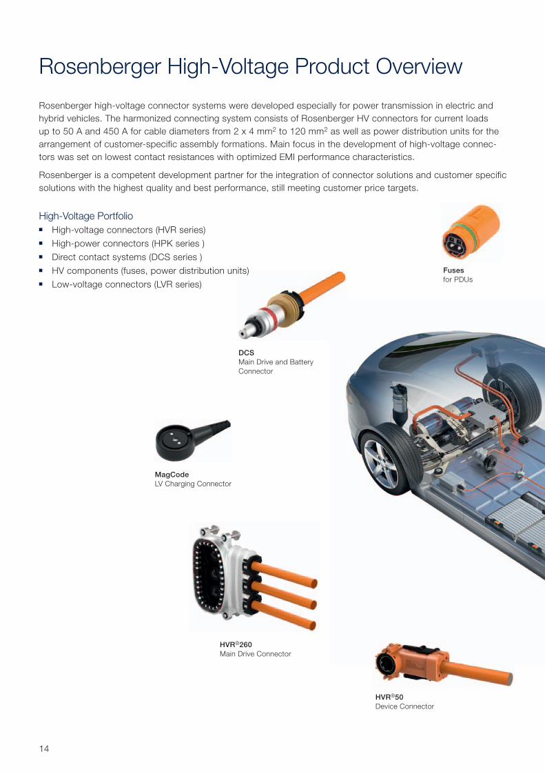
HVR®260
Main Drive Connector
MagCode
LV Charging Connector
DCS
Main Drive and Battery
Connector
Fuses
for PDUs
HVR®50
Device Connector
14
Rosenberger High-Voltage Product Overview
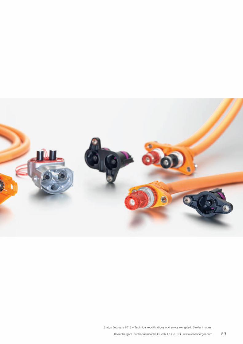
Rosenberger high-voltage connector systems were developed especially for power transmission in electric and
hybrid vehicles. The harmonized connecting system consists of Rosenberger HV connectors for current loads
up to 50 A and 450 A for cable diameters from 2 x 4 mm2 to 120 mm2 as well as power distribution units for the
arrangement of customer-specific assembly formations. Main focus in the development of high- voltage connec-
tors was set on lowest contact resistances with optimized EMI performance characteristics.
Rosenberger is a competent development partner for the integration of connector solutions and customer specific
solutions with the highest quality and best performance, still meeting customer price targets.
High-Voltage Portfolio ■ High-voltage connectors (HVR series)
■ High-power connectors (HPK series )
■ Direct contact systems (DCS series )
■ HV components (fuses, power distribution units)
■ Low-voltage connectors (LVR series)
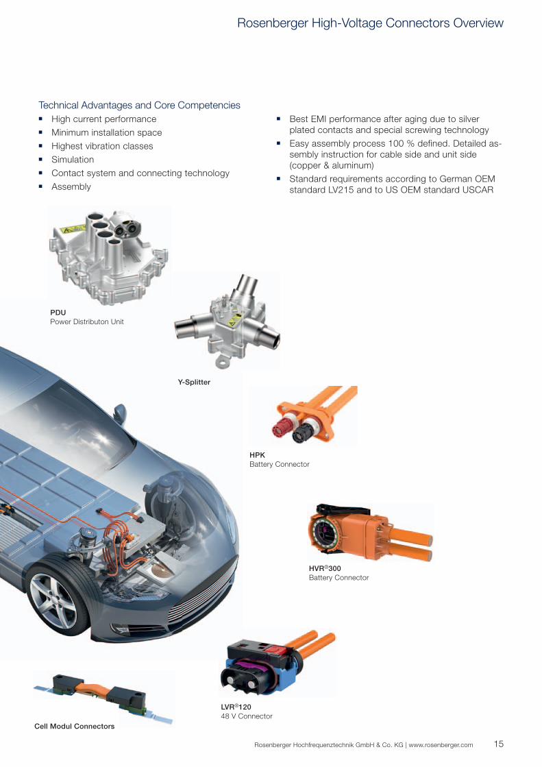
Cell Modul Connectors
PDU
Power Distributon Unit
HPK
Battery Connector
HVR®300
Battery Connector
LVR®120
48 V Connector
Y-Splitter
15Rosenberger Hochfrequenztechnik GmbH & Co. KG | www.rosenberger.com
Technical Advantages and Core Competencies ■ High current performance
■ Minimum installation space
■ Highest vibration classes
■ Simulation
■ Contact system and connecting technology
■ Assembly
■ Best EMI performance after aging due to silver
plated contacts and special screwing technology
■ Easy assembly process 100 % defined. Detailed as-
sembly instruction for cable side and unit side
(copper & aluminum)
■ Standard requirements according to German OEM
standard LV215 and to US OEM standard USCAR
Rosenberger High-Voltage Connectors Overview
16
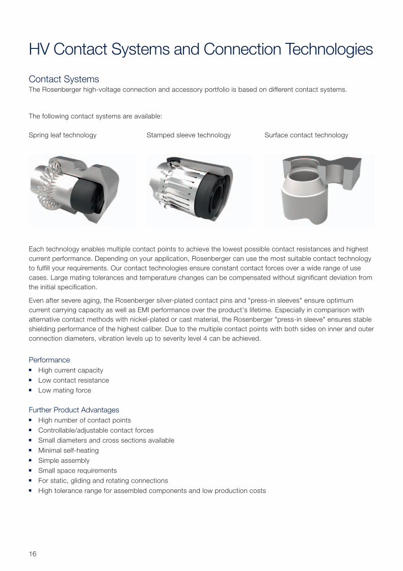
Contact SystemsThe Rosenberger high-voltage connection and accessory portfolio is based on different contact systems.
The following contact systems are available:
Each technology enables multiple contact points to achieve the lowest possible contact resistances and highest
current performance. Depending on your application, Rosenberger can use the most suitable contact technology
to fulfill your requirements. Our contact technologies ensure constant contact forces over a wide range of use
cases. Large mating tolerances and temperature changes can be compensated without significant deviation from
the initial specification.
Even after severe aging, the Rosenberger silver-plated contact pins and "press-in sleeves" ensure optimum
current carrying capacity as well as EMI performance over the product's lifetime. Especially in comparison with
alternative contact methods with nickel-plated or cast material, the Rosenberger "press-in sleeve" ensures stable
shielding performance of the highest caliber. Due to the multiple contact points with both sides on inner and outer
connection diameters, vibration levels up to severity level 4 can be achieved.
Performance ■ High current capacity
■ Low contact resistance
■ Low mating force
Further Product Advantages ■ High number of contact points
■ Controllable/adjustable contact forces
■ Small diameters and cross sections available
■ Minimal self-heating
■ Simple assembly
■ Small space requirements
■ For static, gliding and rotating connections
■ High tolerance range for assembled components and low production costs
Spring leaf technology Stamped sleeve technology Surface contact technology
HV Contact Systems and Connection Technologies
17Rosenberger Hochfrequenztechnik GmbH & Co. KG | www.rosenberger.com
Connection TechnologiesRosenberger uses two different methods to create secure electrical and mechanical connections:
crimp connection and ultrasonic welding, which fulfills highest automotive quality standards. Each connection
technology is standardized by automotive harness makers.
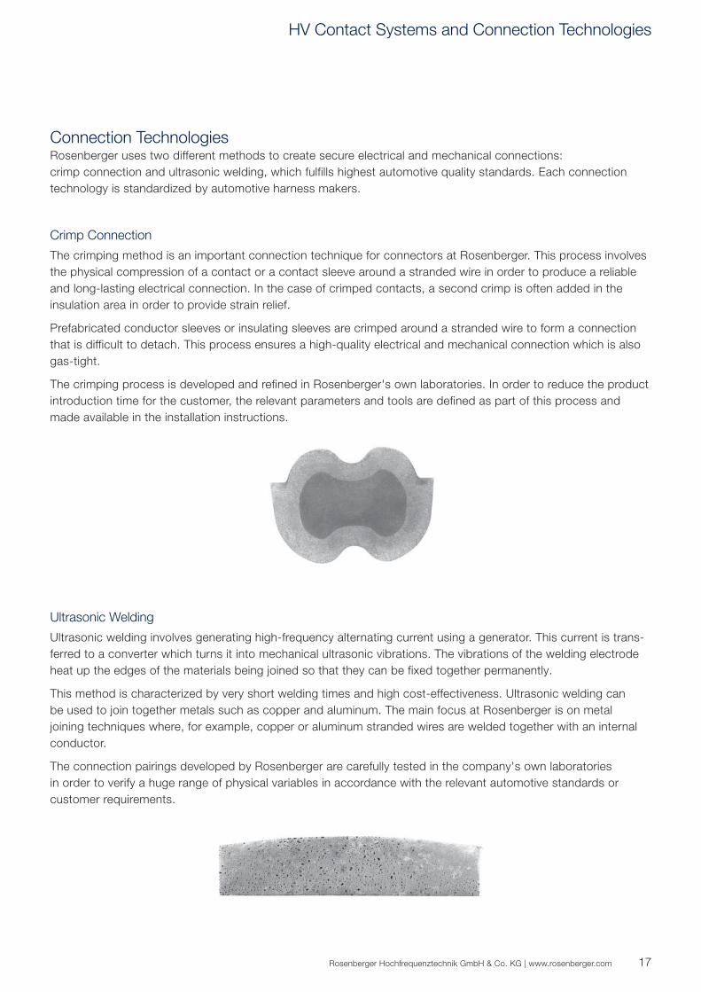
Crimp Connection
The crimping method is an important connection technique for connectors at Rosenberger. This process involves
the physical compression of a contact or a contact sleeve around a stranded wire in order to produce a reliable
and long-lasting electrical connection. In the case of crimped contacts, a second crimp is often added in the
insulation area in order to provide strain relief.
Prefabricated conductor sleeves or insulating sleeves are crimped around a stranded wire to form a connection
that is difficult to detach. This process ensures a high-quality electrical and mechanical connection which is also
gas-tight.
The crimping process is developed and refined in Rosenberger's own laboratories. In order to reduce the product
introduction time for the customer, the relevant parameters and tools are defined as part of this process and
made available in the installation instructions.
Ultrasonic Welding
Ultrasonic welding involves generating high-frequency alternating current using a generator. This current is trans-
ferred to a converter which turns it into mechanical ultrasonic vibrations. The vibrations of the welding electrode
heat up the edges of the materials being joined so that they can be fixed together permanently.
This method is characterized by very short welding times and high cost-effectiveness. Ultrasonic welding can
be used to join together metals such as copper and aluminum. The main focus at Rosenberger is on metal
joining techniques where, for example, copper or aluminum stranded wires are welded together with an internal
conductor.
The connection pairings developed by Rosenberger are carefully tested in the company's own laboratories
in order to verify a huge range of physical variables in accordance with the relevant automotive standards or
customer requirements.
HV Contact Systems and Connection Technologies

18
Rosenberger High-Voltage Connector Matrix
Series Jack/
Plug
Right
Angle
Straight 1-Pole 2-Pole 3-Pole Max.
Current
at 85 °C
Cable Cross
Sections
[mm2]
Cable Connector
HVR®50
Jack
n.a. n.a. 60 A 4, 6
Plug n.a.
HVR®200
Jack n.a.
n.a. n.a. 210 A 16, 25, 35
Plug
HVR®260
Jack n.a.
n.a. n.a. 270 A 50, 70
Plug n.a.
HVR®300
Jack n.a.
n.a. n.a. 320 A50 on request,
70
Plug n.a.
HVR®420
Jack n.a.
n.a. n.a. 450 A35 on request,
70, 95, 120
Plug n.a.
HPK
Jack
n.a. 275 A 16, 25, 35, 50
Plug
DCS
Jack n.a.
n.a. n.a. 340 A 35, 50, 70
Plug n.a.
LVR®120
Jack n.a.
n.a. n.a. 120 A 16
Plug n.a.
19Rosenberger Hochfrequenztechnik GmbH & Co. KG | www.rosenberger.com
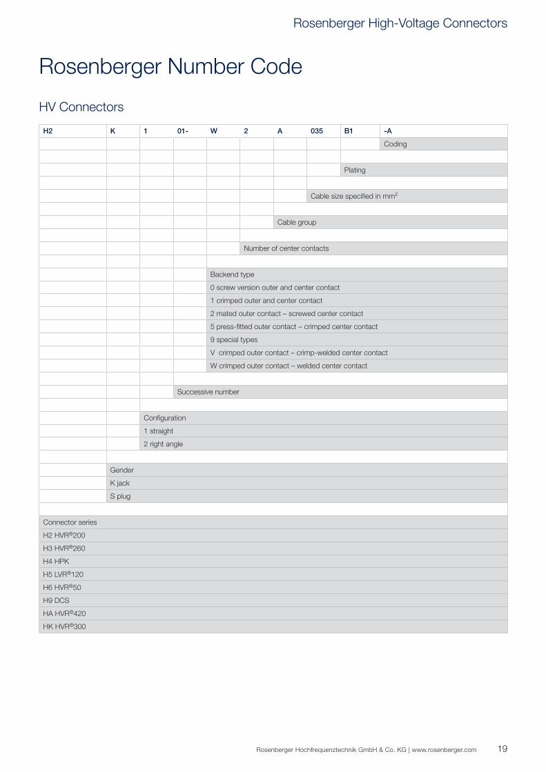
HV Connectors
Rosenberger Number Code
H2 K 1 01- W 2 A 035 B1 -A
Coding
Plating
Cable size specifi ed in mm²
Cable group
Number of center contacts
Backend type
0 screw version outer and center contact
1 crimped outer and center contact
2 mated outer contact – screwed center contact
5 press-fi tted outer contact – crimped center contact
9 special types
V crimped outer contact – crimp-welded center contact
W crimped outer contact – welded center contact
Successive number
Confi guration
1 straight
2 right angle
Gender
K jack
S plug
Connector series
H2 HVR®200
H3 HVR®260
H4 HPK
H5 LVR®120
H6 HVR®50
H9 DCS
HA HVR®420
HK HVR®300
Rosenberger High-Voltage Connectors
20
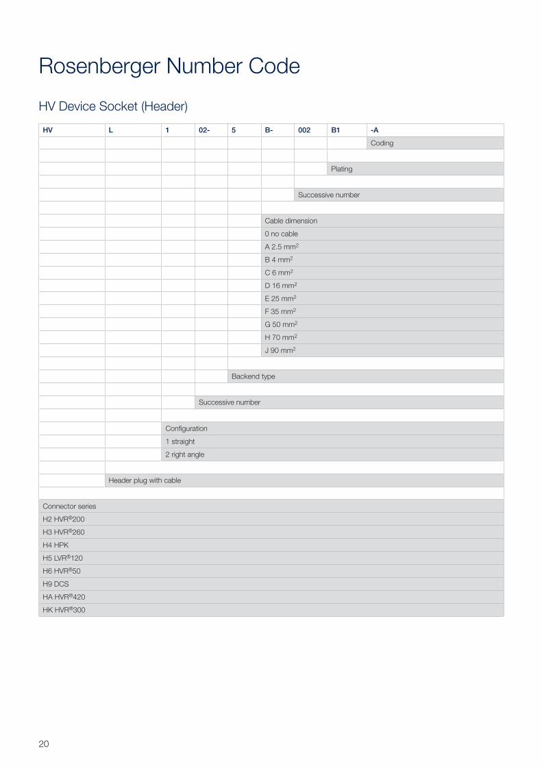
HV Device Socket (Header)
Rosenberger Number Code
HV L 1 02- 5 B- 002 B1 -A
Coding
Plating
Successive number
Cable dimension
0 no cable
A 2.5 mm2
B 4 mm2
C 6 mm2
D 16 mm2
E 25 mm2
F 35 mm2
G 50 mm2
H 70 mm2
J 90 mm2
Backend type
Successive number
Confi guration
1 straight
2 right angle
Header plug with cable
Connector series
H2 HVR®200
H3 HVR®260
H4 HPK
H5 LVR®120
H6 HVR®50
H9 DCS
HA HVR®420
HK HVR®300
21Rosenberger Hochfrequenztechnik GmbH & Co. KG | www.rosenberger.com
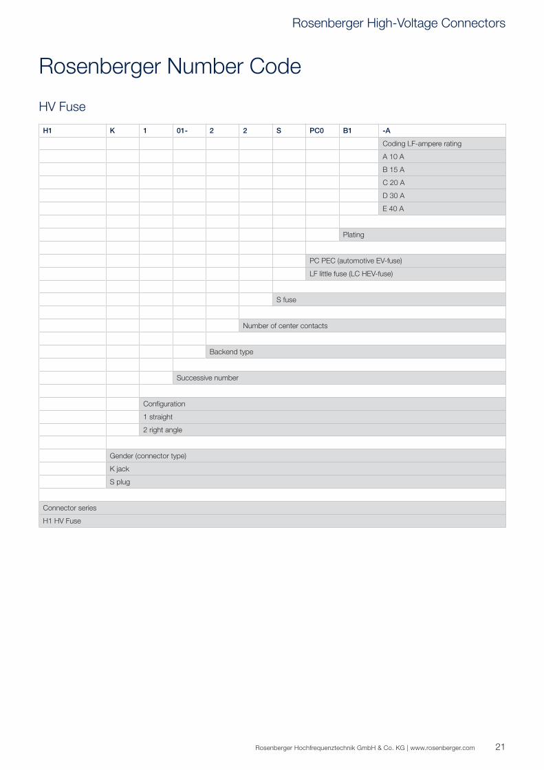
Rosenberger Number Code
HV Fuse
H1 K 1 01- 2 2 S PC0 B1 -A
Coding LF-ampere rating
A 10 A
B 15 A
C 20 A
D 30 A
E 40 A
Plating
PC PEC (automotive EV-fuse)
LF little fuse (LC HEV-fuse)
S fuse
Number of center contacts
Backend type
Successive number
Confi guration
1 straight
2 right angle
Gender (connector type)
K jack
S plug
Connector series
H1 HV Fuse
Rosenberger High-Voltage Connectors
22
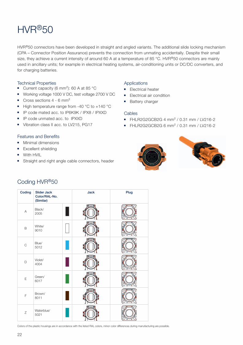
HVR®50
HVR®50 connectors have been developed in straight and angled variants. The additional slide locking mechanism
(CPA – Connector Position Assurance) prevents the connection from unmating accidentally. Despite their small
size, they achieve a current intensity of around 60 A at a temperature of 85 °C. HVR®50 connectors are mainly
used in ancillary units; for example in electrical heating systems, air-conditioning units or DC/DC converters, and
for charging batteries.
Technical Properties ■ Current capacity (6 mm²): 60 A at 85 °C
■ Working voltage 1000 V DC, test voltage 2700 V DC
■ Cross sections 4 - 6 mm²
■ High temperature range from -40 °C to +140 °C
■ IP code mated acc. to IP6K9K / IPX8 / IPXXD
■ IP code unmated acc. to IPXXD
■ Vibration class II acc. to LV215, PG17
Features and Benefits ■ Minimal dimensions
■ Excellent shielding
■ With HVIL
■ Straight and right angle cable connectors, header
Applications ■ Electrical heater
■ Electrical air condition
■ Battery charger
Cables ■ FHLR2G2GCB2G 4 mm² / 0.31 mm / LV216-2
■ FHLR2G2GCB2G 6 mm² / 0.31 mm / LV216-2
Coding HVR®50
Coding Slider Jack
Color/RAL-No.
(Similar)
Jack Plug
ABlack/
2005
BWhite/
9010
CBlue/
5012
DViolet/
4004
EGreen/
6017
FBrown/
8011
ZWaterblue/
5021
Colors of the plastic housings are in accordance with the listed RAL colors, minor color differences during manufacturing are possible.
0
5
10
15
20
25
30
35
40
45
50
55
60
65
70
75
80
0 10 20 30 40 50 60 70 80 90 100 110 120 130 140 150 160 170 180 190
Curr
ent [
A]
Temperature [°C]
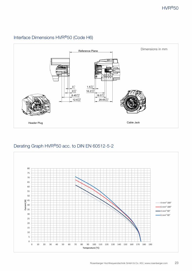
4 mm² 180°
6 mm² 180°
4 mm² 90°
6 mm² 90°
R
1.5+0.2-0.2
16.2+0.5-0.5
3+1-1
12.6+0.6-0.6
3+0.5-0.5
18.5+0.6-1.08.45+0.6
-1.0
28.65+0.3-0.3
C
23Rosenberger Hochfrequenztechnik GmbH & Co. KG | www.rosenberger.com
Interface Dimensions HVR®50 (Code H6)
Derating Graph HVR®50 acc. to DIN EN 60512-5-2
Dimensions in mm
HVR®50
24
Technical Data HVR®50 (Code H6)
Electrical Data
Insulation resistance ≥ 200 MΩ at 1000 V DC
Voltage class B
60 V DC < U ≤ 1500 V DC
30 V AC < U ≤ 1000 V AC
Center contact resistance ≤ 1.36 mΩ
Outer contact resistance ≤ 10 mΩ
Current capacity for 6 mm² 60 A at 85 °C
Test voltage 2700 V DC
Working voltage 1000 V DC
High-Voltage Interlock (HVIL) yes
Power pins min. 1 mm advanced
Mechanical Data
Mating cycles ≥ 50
Engagement force ≤ 75 N
Coding effi ciency ≥ 300 N
Cable cross sections 4 mm², 6 mm²
Cable connection angle 90°, 180°
Vibration class LV215 PG17– II
IP class (mated) IP6K9K / IPX8 / IPXXD
IP class (unmated) IPXXB
Environmental Data
Temperature range -40 °C to +140 °C
RoHS compliant
Rosenberger connectors fulfi ll in principle the indicated data of the technical data. Individual values of connectors may deviate depending upon application, design, type of cable,
assembly method and execution. Specifi c data sheets for particular products can be provided on request from your Rosenberger sales partner.
Applicable Standards
Interface according to Rosenberger RN_111-01
25Rosenberger Hochfrequenztechnik GmbH & Co. KG | www.rosenberger.com
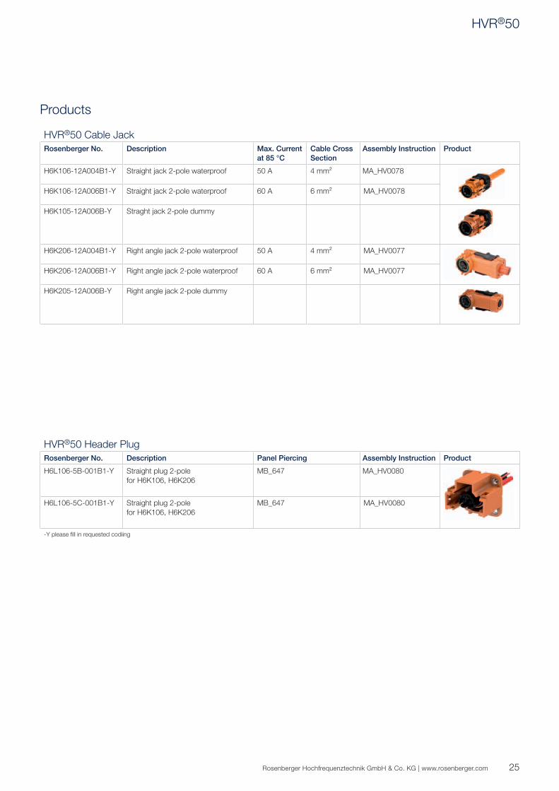
Products
HVR®50 Header Plug
Rosenberger No. Description Panel Piercing Assembly Instruction Product
H6L106-5B-001B1-Y Straight plug 2-pole
for H6K106, H6K206
MB_647 MA_HV0080
H6L106-5C-001B1-Y Straight plug 2-pole
for H6K106, H6K206
MB_647 MA_HV0080
-Y please fi ll in requested codiing
HVR®50 Cable Jack
Rosenberger No. Description Max. Current
at 85 °C
Cable Cross
Section
Assembly Instruction Product
H6K106-12A004B1-Y Straight jack 2-pole waterproof 50 A 4 mm² MA_HV0078
H6K106-12A006B1-Y Straight jack 2-pole waterproof 60 A 6 mm² MA_HV0078
H6K105-12A006B-Y Straght jack 2-pole dummy
H6K206-12A004B1-Y Right angle jack 2-pole waterproof 50 A 4 mm² MA_HV0077
H6K206-12A006B1-Y Right angle jack 2-pole waterproof 60 A 6 mm² MA_HV0077
H6K205-12A006B-Y Right angle jack 2-pole dummy
HVR®50
26
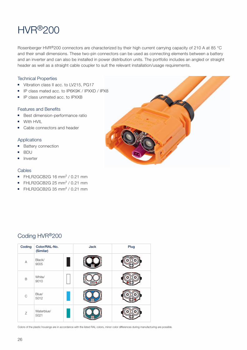
Coding HVR®200
HVR®200
Rosenberger HVR®200 connectors are characterized by their high current carrying capacity of 210 A at 85 °C
and their small dimensions. These two-pin connectors can be used as connecting elements between a battery
and an inverter and can also be installed in power distribution units. The portfolio includes an angled or straight
header as well as a straight cable coupler to suit the relevant installation/usage requirements.
Technical Properties ■ Vibration class II acc. to LV215, PG17
■ IP class mated acc. to IP6K9K / IPXXD / IPX8
■ IP class unmated acc. to IPXXB
Features and Benefits ■ Best dimension-performance ratio
■ With HVIL
■ Cable connectors and header
Applications ■ Battery connection
■ BDU
■ Inverter
Cables ■ FHLR2GCB2G 16 mm² / 0.21 mm
■ FHLR2GCB2G 25 mm² / 0.21 mm
■ FHLR2GCB2G 35 mm² / 0.21 mm
Coding Color/RAL-No.
(Similar)
Jack Plug
ABlack/
9005
BWhite/
9010
CBlue/
5012
ZWaterblue/
5021
Colors of the plastic housings are in accordance with the listed RAL colors, minor color differences during manufacturing are possible.
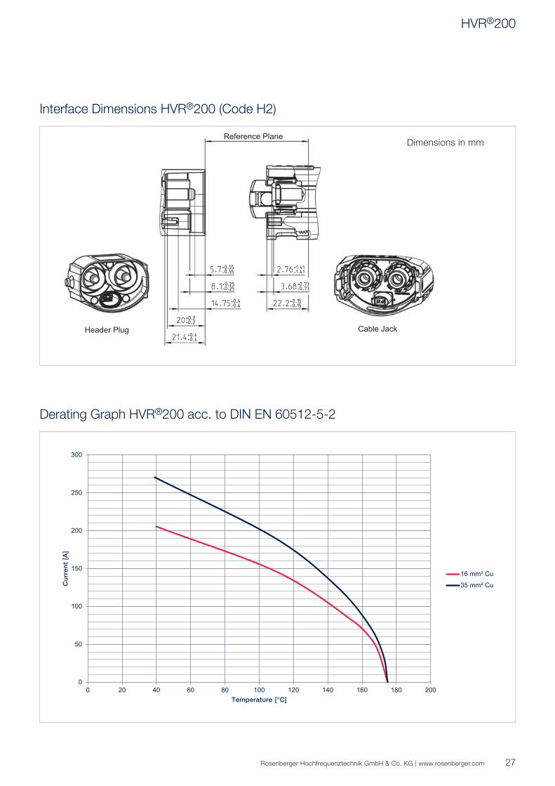
0
50
100
150
200
250
300
0 20 40 60 80 100 120 140 160 180 200
Cu
rre
nt
[A]
Temperature [°C]
16 mm² Cu
35 mm² Cu
27Rosenberger Hochfrequenztechnik GmbH & Co. KG | www.rosenberger.com
Interface Dimensions HVR®200 (Code H2)
Derating Graph HVR®200 acc. to DIN EN 60512-5-2
Dimensions in mm
HVR®200
28
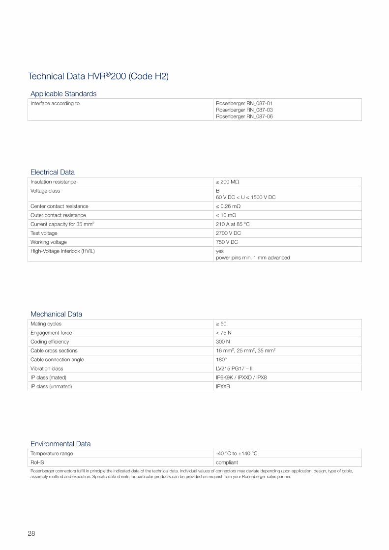
Technical Data HVR®200 (Code H2)
Electrical Data
Insulation resistance ≥ 200 MΩ
Voltage class B
60 V DC < U ≤ 1500 V DC
Center contact resistance ≤ 0.26 mΩ
Outer contact resistance ≤ 10 mΩ
Current capacity for 35 mm² 210 A at 85 °C
Test voltage 2700 V DC
Working voltage 750 V DC
High-Voltage Interlock (HVIL) yes
power pins min. 1 mm advanced
Mechanical Data
Mating cycles ≥ 50
Engagement force < 75 N
Coding effi ciency 300 N
Cable cross sections 16 mm², 25 mm², 35 mm²
Cable connection angle 180°
Vibration class LV215 PG17 – II
IP class (mated) IP6K9K / IPXXD / IPX8
IP class (unmated) IPXXB
Environmental Data
Temperature range -40 °C to +140 °C
RoHS compliant
Rosenberger connectors fulfi ll in principle the indicated data of the technical data. Individual values of connectors may deviate depending upon application, design, type of cable,
assembly method and execution. Specifi c data sheets for particular products can be provided on request from your Rosenberger sales partner.
Applicable Standards
Interface according to Rosenberger RN_087-01
Rosenberger RN_087-03
Rosenberger RN_087-06
29Rosenberger Hochfrequenztechnik GmbH & Co. KG | www.rosenberger.com
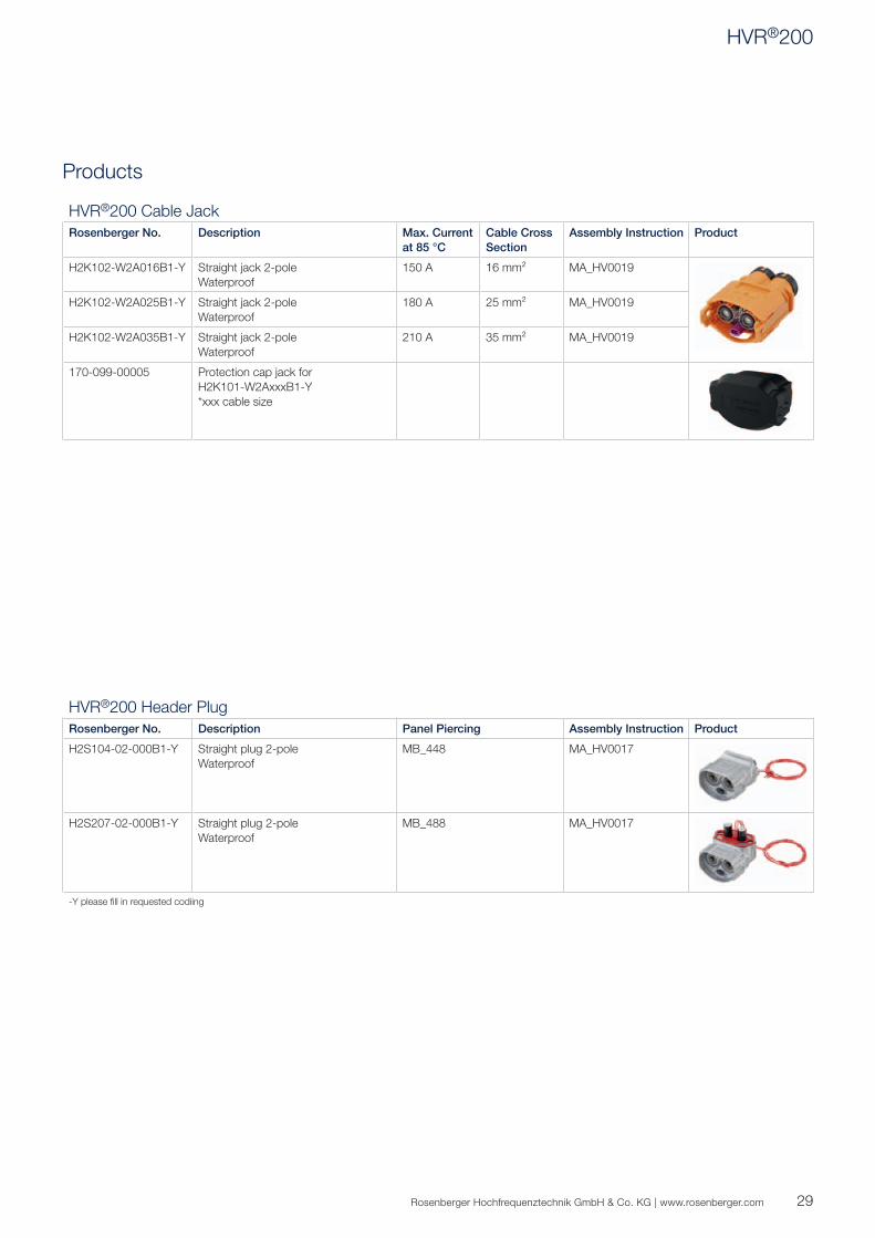
Products
HVR®200 Header Plug
Rosenberger No. Description Panel Piercing Assembly Instruction Product
H2S104-02-000B1-Y Straight plug 2-pole
Waterproof
MB_448 MA_HV0017
H2S207-02-000B1-Y Straight plug 2-pole
Waterproof
MB_488 MA_HV0017
-Y please fi ll in requested codiing
HVR®200 Cable Jack
Rosenberger No. Description Max. Current
at 85 °C
Cable Cross
Section
Assembly Instruction Product
H2K102-W2A016B1-Y Straight jack 2-pole
Waterproof
150 A 16 mm² MA_HV0019
H2K102-W2A025B1-Y Straight jack 2-pole
Waterproof
180 A 25 mm² MA_HV0019
H2K102-W2A035B1-Y Straight jack 2-pole
Waterproof
210 A 35 mm² MA_HV0019
170-099-00005 Protection cap jack for
H2K101-W2AxxxB1-Y
*xxx cable size
HVR®200
30
HVR®260
The 3-pole HVR®260 connector system for collective shield applications is used to connect electric motors up to
a continuous current of 270 A. Despite its lightweight aluminum housing, it also meets extremely high temperature
requirements from -40 °C to +150 °C and achieves vibration severity level IV. Customer-specific variants are avail-
able on request.
Technical Properties ■ Current capacity (50 mm²): 270 A at 85 °C
■ Cross sections: 50 - 70 mm²
■ Maximum operation altitude: 5,500 m sealevel
■ Voltage class: HV-2B
■ Mating cycles: ≥ 50
■ Contact resistance: ≤ 0.26 mΩ
■ Working voltage 850 V DC
■ IP class mated acc. to IP 6K9K / IP X8 / IPXXD
■ IP class unmated acc. to IPXXB
■ Temperature range -40 °C to +150 °C
■ Vibration class IV acc. to LV215, PG17
Features and Benefits ■ RoHS: compliant
■ Qualification: according to LV215-2
■ Right angle connector
■ 3–pole connector
■ Costumer specific solutions
Applications ■ E-motor
■ High-voltage connector

31Rosenberger Hochfrequenztechnik GmbH & Co. KG | www.rosenberger.com
R
min.18
min.19.8
2.9+0.4-0.4
7.9+0.3-0.3
min.15.2
13+1-1
19.6+0.25-0.25
16+0.25-0.25
14.5+0.3-0.3
C
Interface Dimensions HVR®260 (Code H3)
HVR®260 Header Plug
HVR®260 Cable Jack
Dimensions in mm
HVR®260
32
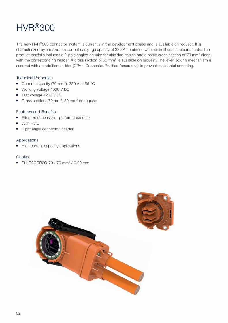
HVR®300
The new HVR®300 connector system is currently in the development phase and is available on request. It is
characterized by a maximum current carrying capacity of 320 A combined with minimal space requirements. The
product portfolio includes a 2-pole angled coupler for shielded cables and a cable cross section of 70 mm² along
with the corresponding header. A cross section of 50 mm² is available on request. The lever locking mechanism is
secured with an additional slider (CPA – Connector Position Assurance) to prevent accidental unmating.
Technical Properties ■ Current capacity (70 mm²): 320 A at 85 °C
■ Working voltage 1000 V DC
■ Test voltage 4200 V DC
■ Cross sections 70 mm², 50 mm² on request
Features and Benefits ■ Effective dimension – performance ratio
■ With HVIL
■ Right angle connector, header
Applications ■ High current capacity applications
Cables ■ FHLR2GCB2G-70 / 70 mm² / 0.20 mm
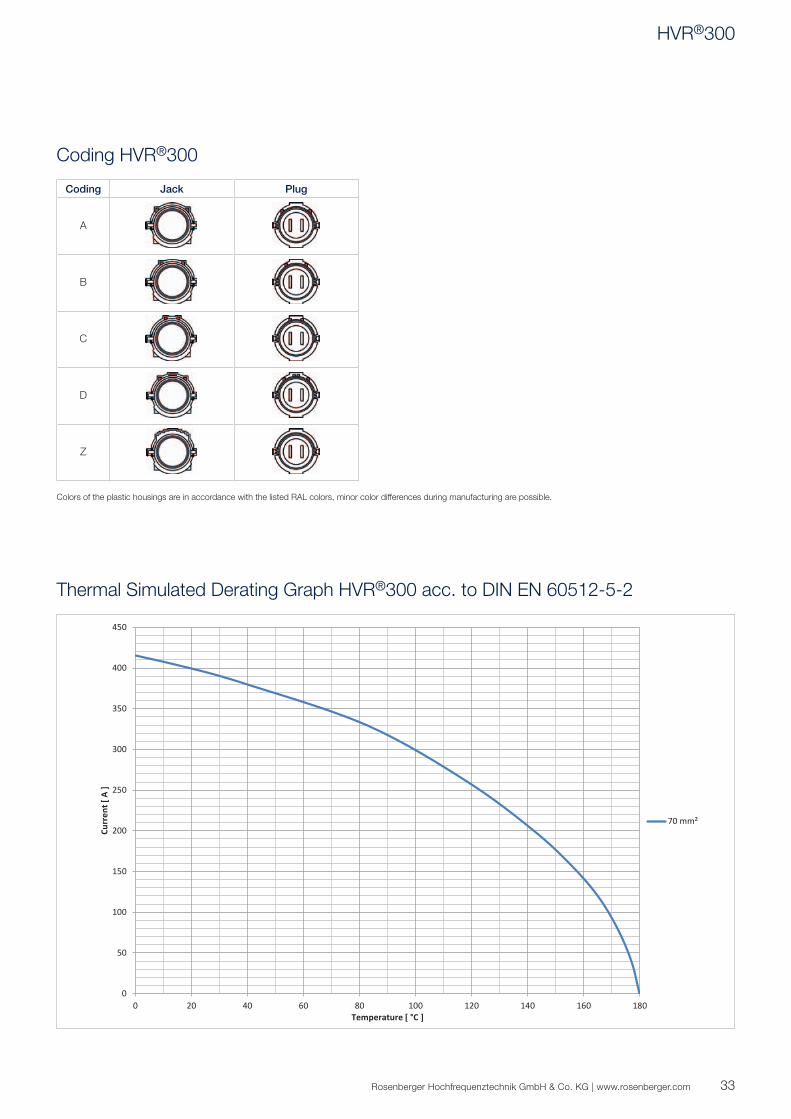
0
50
100
150
200
250
300
350
400
450
0 20 40 60 80 100 120 140 160 180
Curr
ent [
A ]
Temperature [ °C ]
70 mm²
33Rosenberger Hochfrequenztechnik GmbH & Co. KG | www.rosenberger.com
Coding HVR®300
Thermal Simulated Derating Graph HVR®300 acc. to DIN EN 60512-5-2
Coding Jack Plug
A
B
C
D
Z
Colors of the plastic housings are in accordance with the listed RAL colors, minor color differences during manufacturing are possible.
HVR®300
34
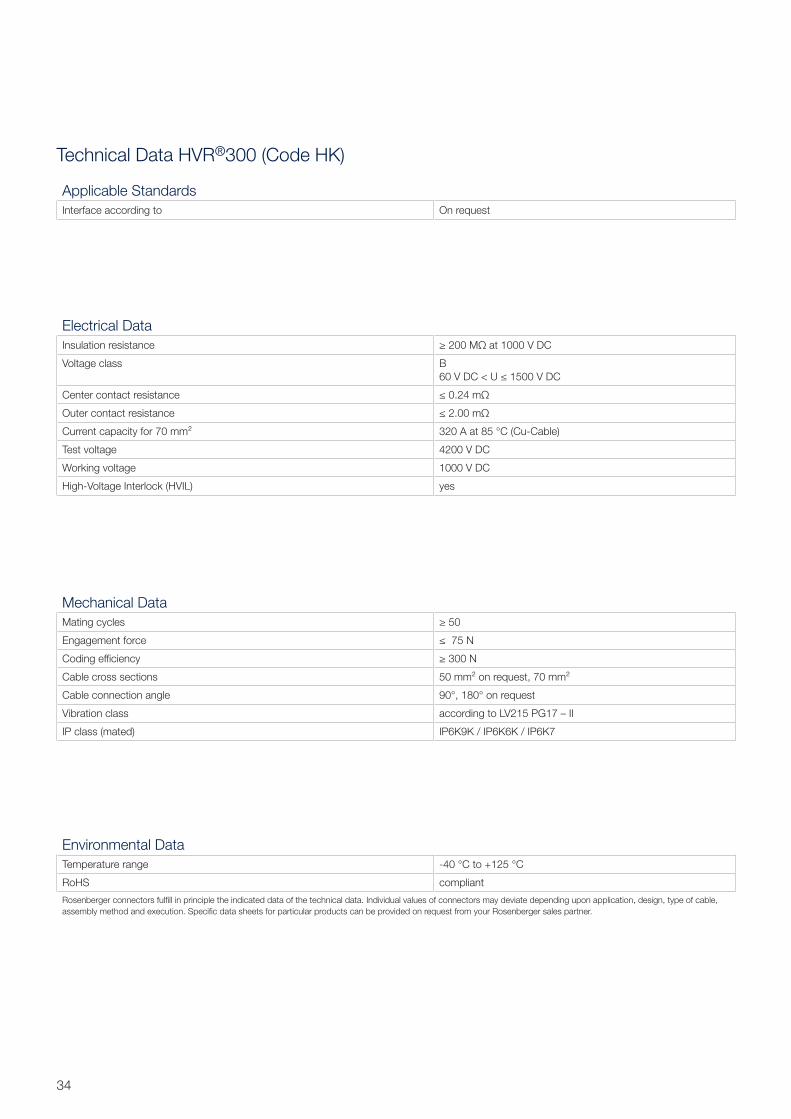
Technical Data HVR®300 (Code HK)
Electrical Data
Insulation resistance ≥ 200 MΩ at 1000 V DC
Voltage class B
60 V DC < U ≤ 1500 V DC
Center contact resistance ≤ 0.24 mΩ
Outer contact resistance ≤ 2.00 mΩ
Current capacity for 70 mm² 320 A at 85 °C (Cu-Cable)
Test voltage 4200 V DC
Working voltage 1000 V DC
High-Voltage Interlock (HVIL) yes
Mechanical Data
Mating cycles ≥ 50
Engagement force ≤ 75 N
Coding effi ciency ≥ 300 N
Cable cross sections 50 mm² on request, 70 mm²
Cable connection angle 90°, 180° on request
Vibration class according to LV215 PG17 – II
IP class (mated) IP6K9K / IP6K6K / IP6K7
Environmental Data
Temperature range -40 °C to +125 °C
RoHS compliant
Rosenberger connectors fulfi ll in principle the indicated data of the technical data. Individual values of connectors may deviate depending upon application, design, type of cable,
assembly method and execution. Specifi c data sheets for particular products can be provided on request from your Rosenberger sales partner.
Applicable Standards
Interface according to On request
35Rosenberger Hochfrequenztechnik GmbH & Co. KG | www.rosenberger.com
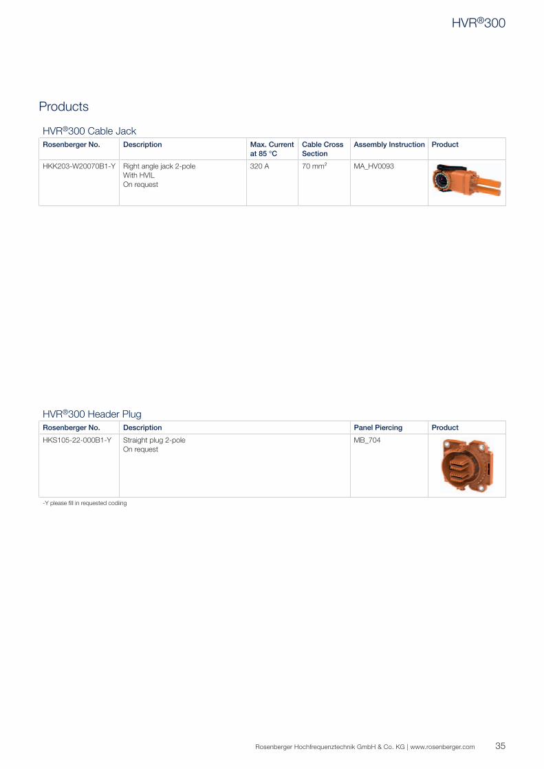
Products
HVR®300 Header Plug
Rosenberger No. Description Panel Piercing Product
HKS105-22-000B1-Y Straight plug 2-pole
On request
MB_704
-Y please fi ll in requested codiing
HVR®300 Cable Jack
Rosenberger No. Description Max. Current
at 85 °C
Cable Cross
Section
Assembly Instruction Product
HKK203-W20070B1-Y Right angle jack 2-pole
With HVIL
On request
320 A 70 mm² MA_HV0093
HVR®300
36
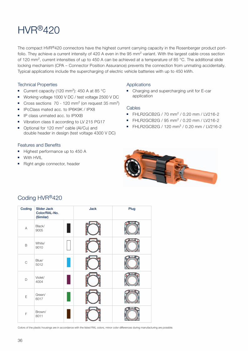
Coding HVR®420
HVR®420
The compact HVR®420 connectors have the highest current carrying capacity in the Rosenberger product port-
folio. They achieve a current intensity of 420 A even in the 95 mm² variant. With the largest cable cross section
of 120 mm², current intensities of up to 450 A can be achieved at a temperature of 85 °C. The additional slide
locking mechanism (CPA – Connector Position Assurance) prevents the connection from unmating accidentally.
Typical applications include the supercharging of electric vehicle batteries with up to 450 kWh.
Technical Properties ■ Current capacity (120 mm²): 450 A at 85 °C
■ Working voltage 1000 V DC / test voltage 2500 V DC
■ Cross sections 70 - 120 mm² (on request 35 mm²)
■ IPcClass mated acc. to IP6K9K / IPX8
■ IP class unmated acc. to IPXXB
■ Vibration class II according to LV 215 PG17
■ Optional for 120 mm² cable (Al/Cu) and
double header in design (test voltage 4300 V DC)
Features and Benefits ■ Highest performance up to 450 A
■ With HVIL
■ Right angle connector, header
Applications ■ Charging and supercharging unit for E-car
application
Cables ■ FHLR2GCB2G / 70 mm² / 0.20 mm / LV216-2
■ FHLR2GCB2G / 95 mm² / 0.20 mm / LV216-2
■ FHLR2GCB2G / 120 mm² / 0.20 mm / LV216-2
Coding Slider Jack
Color/RAL-No.
(Similar)
Jack Plug
ABlack/
9005
BWhite/
9010
CBlue/
5012
DViolet/
4004
EGreen/
6017
FBrown/
8011
Colors of the plastic housings are in accordance with the listed RAL colors, minor color differences during manufacturing are possible.
0
50
100
150
200
250
300
350
400
450
500
550
600
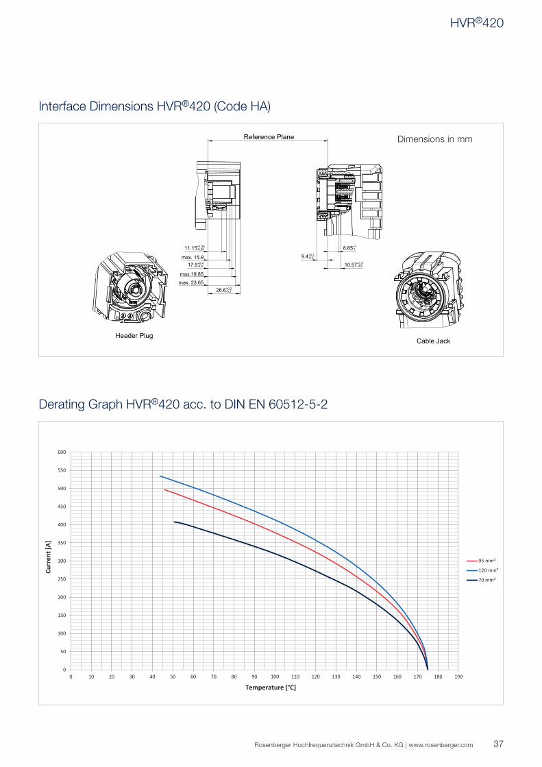
0 10 20 30 40 50 60 70 80 90 100 110 120 130 140 150 160 170 180 190
Curr
ent [
A]
Temperature [°C]
95 mm²
120 mm²
70 mm²
R
max. 23.65
17.9+0.4-0.9
max. 15.9 9.4+0.2-0.2
max.19.85
26.6+0.2-0.2
11.15+1.25-0.50
10.57+0.9-0.9
8.65+1-1
C
Dimensions in mm
37Rosenberger Hochfrequenztechnik GmbH & Co. KG | www.rosenberger.com
Interface Dimensions HVR®420 (Code HA)
Derating Graph HVR®420 acc. to DIN EN 60512-5-2
HVR®420
38
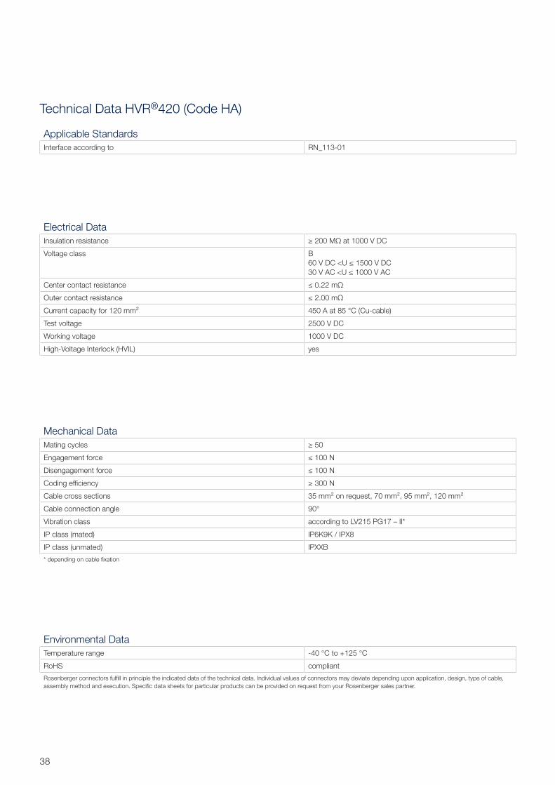
Technical Data HVR®420 (Code HA)
Electrical Data
Insulation resistance ≥ 200 MΩ at 1000 V DC
Voltage class B
60 V DC <U ≤ 1500 V DC
30 V AC <U ≤ 1000 V AC
Center contact resistance ≤ 0.22 mΩ
Outer contact resistance ≤ 2.00 mΩ
Current capacity for 120 mm² 450 A at 85 °C (Cu-cable)
Test voltage 2500 V DC
Working voltage 1000 V DC
High-Voltage Interlock (HVIL) yes
Mechanical Data
Mating cycles ≥ 50
Engagement force ≤ 100 N
Disengagement force ≤ 100 N
Coding effi ciency ≥ 300 N
Cable cross sections 35 mm² on request, 70 mm², 95 mm², 120 mm²
Cable connection angle 90°
Vibration class according to LV215 PG17 – II*
IP class (mated) IP6K9K / IPX8
IP class (unmated) IPXXB
* depending on cable fi xation
Environmental Data
Temperature range -40 °C to +125 °C
RoHS compliant
Rosenberger connectors fulfi ll in principle the indicated data of the technical data. Individual values of connectors may deviate depending upon application, design, type of cable,
assembly method and execution. Specifi c data sheets for particular products can be provided on request from your Rosenberger sales partner.
Applicable Standards
Interface according to RN_113-01
39Rosenberger Hochfrequenztechnik GmbH & Co. KG | www.rosenberger.com
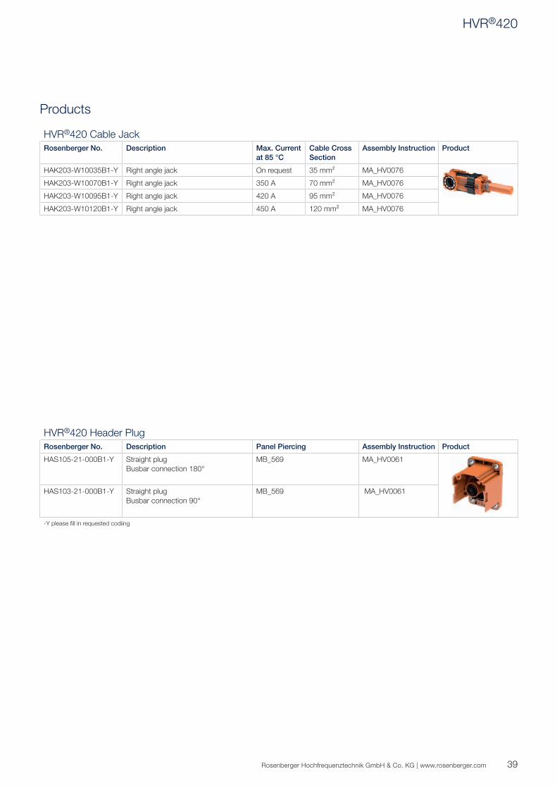
Products
HVR®420 Header Plug
Rosenberger No. Description Panel Piercing Assembly Instruction Product
HAS105-21-000B1-Y Straight plug
Busbar connection 180°
MB_569 MA_HV0061
HAS103-21-000B1-Y Straight plug
Busbar connection 90°
MB_569 MA_HV0061
-Y please fi ll in requested codiing
HVR®420 Cable Jack
Rosenberger No. Description Max. Current
at 85 °C
Cable Cross
Section
Assembly Instruction Product
HAK203-W10035B1-Y Right angle jack On request 35 mm² MA_HV0076
HAK203-W10070B1-Y Right angle jack 350 A 70 mm² MA_HV0076
HAK203-W10095B1-Y Right angle jack 420 A 95 mm² MA_HV0076
HAK203-W10120B1-Y Right angle jack 450 A 120 mm² MA_HV0076
HVR®420
40
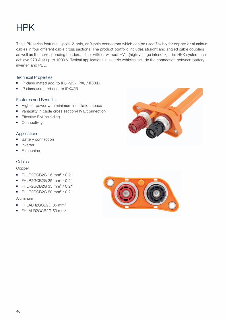
HPK
The HPK series features 1-pole, 2-pole, or 3-pole connectors which can be used flexibly for copper or aluminum
cables in four different cable cross sections. The product portfolio includes straight and angled cable couplers
as well as the corresponding headers, either with or without HVIL (high-voltage interlock). The HPK system can
achieve 270 A at up to 1000 V. Typical applications in electric vehicles include the connection between battery,
inverter, and PDU.
Technical Properties ■ IP class mated acc. to IP6K9K / IPX8 / IPXXD
■ IP class unmated acc. to IPXX2B
Features and Benefits ■ Highest power with minimum installation space
■ Variability in cable cross section/HVIL/connection
■ Effective EMI shielding
■ Connectivity
Applications ■ Battery connection
■ Inverter
■ E-machine
Cables
Copper
■ FHLR2GCB2G 16 mm² / 0.21
■ FHLR2GCB2G 25 mm² / 0.21
■ FHLR2GCB2G 35 mm² / 0.21
■ FHLR2GCB2G 50 mm² / 0.21
Aluminum
■ FHLALR2GCB2G 35 mm²
■ FHLALR2GCB2G 50 mm²
0
50
100
150
200
250
300
350
0 20 40 60 80 100 120 140 160 180 200
Curr
ent [
A]
Temperature [°C]
16 mm²
25 mm²
35 mm²
50 mm²
0
50
100
150
200
250
300
0 20 40 60 80 100 120 140 160 180 200
Curr
ent [
A]
Temperature [°C]
35 mm² Al
50 mm² Al
41Rosenberger Hochfrequenztechnik GmbH & Co. KG | www.rosenberger.com
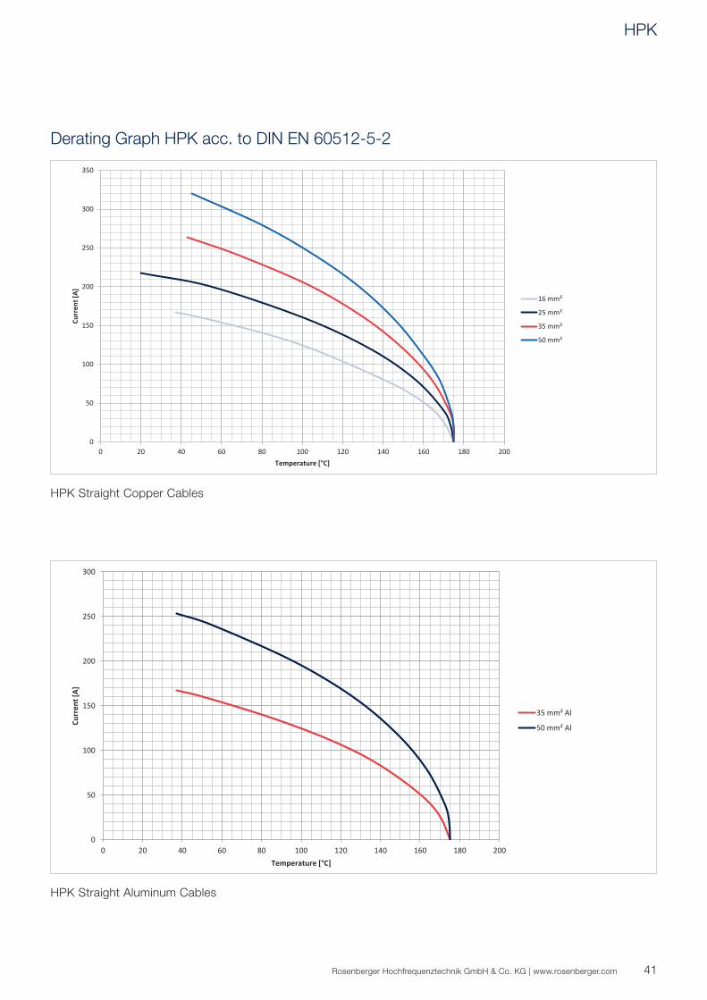
Derating Graph HPK acc. to DIN EN 60512-5-2
HPK Straight Copper Cables
HPK Straight Aluminum Cables
HPK
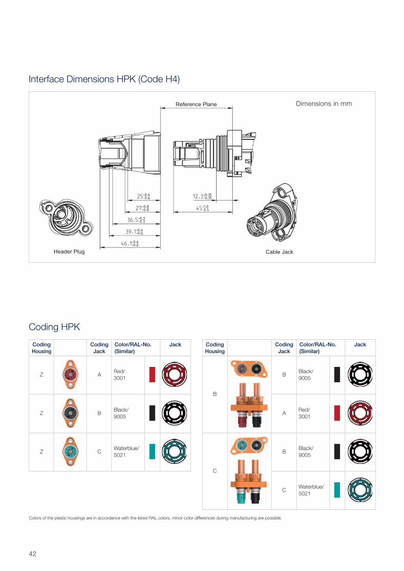
Coding HPK
Coding
Housing
Coding
Jack
Color/RAL-No.
(Similar)
Jack
Z ARed/
3001
Z BBlack/
9005
Z CWaterblue/
5021
Coding
Housing
Coding
Jack
Color/RAL-No.
(Similar)
Jack
B
BBlack/
9005
ARed/
3001
C
BBlack/
9005
CWaterblue/
5021
Interface Dimensions HPK (Code H4)
Dimensions in mm
42
Colors of the plastic housings are in accordance with the listed RAL colors, minor color differences during manufacturing are possible.
43Rosenberger Hochfrequenztechnik GmbH & Co. KG | www.rosenberger.com
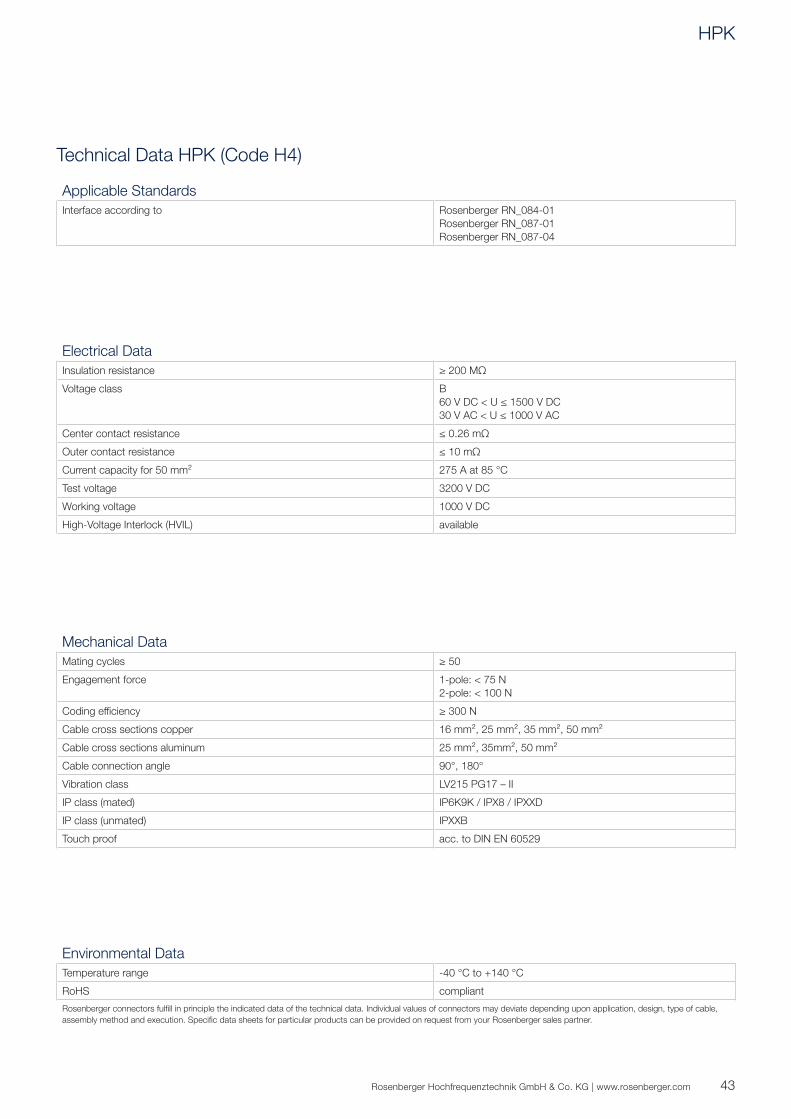
Technical Data HPK (Code H4)
Electrical Data
Insulation resistance ≥ 200 MΩ
Voltage class B
60 V DC < U ≤ 1500 V DC
30 V AC < U ≤ 1000 V AC
Center contact resistance ≤ 0.26 mΩ
Outer contact resistance ≤ 10 mΩ
Current capacity for 50 mm² 275 A at 85 °C
Test voltage 3200 V DC
Working voltage 1000 V DC
High-Voltage Interlock (HVIL) available
Mechanical Data
Mating cycles ≥ 50
Engagement force 1-pole: < 75 N
2-pole: < 100 N
Coding effi ciency ≥ 300 N
Cable cross sections copper 16 mm², 25 mm², 35 mm², 50 mm²
Cable cross sections aluminum 25 mm², 35mm², 50 mm²
Cable connection angle 90°, 180°
Vibration class LV215 PG17 – II
IP class (mated) IP6K9K / IPX8 / IPXXD
IP class (unmated) IPXXB
Touch proof acc. to DIN EN 60529
Environmental Data
Temperature range -40 °C to +140 °C
RoHS compliant
Rosenberger connectors fulfi ll in principle the indicated data of the technical data. Individual values of connectors may deviate depending upon application, design, type of cable,
assembly method and execution. Specifi c data sheets for particular products can be provided on request from your Rosenberger sales partner.
Applicable Standards
Interface according to Rosenberger RN_084-01
Rosenberger RN_087-01
Rosenberger RN_087-04
HPK
44
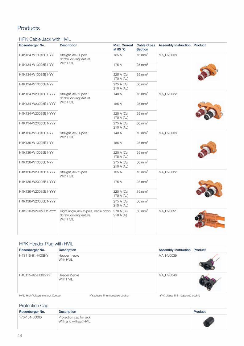
Products
HPK Cable Jack with HVIL
Rosenberger No. Description Max. Current
at 85 °C
Cable Cross
Section
Assembly Instruction Product
H4K134-W10016B1-YY Straight jack 1-pole
Screw locking feature
With HVIL
135 A 16 mm² MA_HV0008
H4K134-W10025B1-YY 175 A 25 mm²
H4K134-W10035B1-YY 225 A (Cu)
170 A (AL)
35 mm²
H4K134-W10050B1-YY 275 A (Cu)
210 A (AL)
50 mm²
H4K134-W20016B1-YYY Straight jack 2-pole
Screw locking feature
With HVIL
140 A 16 mm² MA_HV0022
H4K134-W20025B1-YYY 185 A 25 mm²
H4K134-W20035B1-YYY 225 A (Cu)
170 A (AL)
35 mm²
H4K134-W20050B1-YYY 275 A (Cu)
210 A (AL)
50 mm²
H4K136-W10016B1-YY Straight jack 1-pole
With HVIL
140 A 16 mm² MA_HV0008
H4K136-W10025B1-YY 185 A 25 mm²
H4K136-W10035B1-YY 220 A (Cu)
175 A (AL)
35 mm²
H4K136-W10050B1-YY 275 A (Cu)
210 A (AL)
50 mm²
H4K136-W20016B1-YYY Straight jack 2-pole
With HVIL
135 A 16 mm² MA_HV0022
H4K136-W20025B1-YYY 175 A 25 mm²
H4K136-W20035B1-YYY 225 A (Cu)
170 A (AL)
35 mm²
H4K136-W20050B1-YYY 275 A (Cu)
210 A (AL)
50 mm²
H4K210-W2U050B1-YYY Right angle jack 2-pole, cable down
Screw locking feature
With HVIL
270 A (Cu)
210 A (Al)
50 mm² MA_HV0051
Protection Cap
Rosenberger No. Description Product
170-101-00000 Protection cap for jack
With and without HVIL
HPK Header Plug with HVIL
Rosenberger No. Description Assembly Instruction Product
H4S115-91-H00B-Y Header 1-pole
With HVIL
MA_HV0039
H4S115-92-H00B-YY Header 2-pole
With HVIL
MA_HV0048
HVIL: High-Voltage Interlock Contact -YY: please fi ll-in requested coding -YYY: please fi ll-in requested coding
45Rosenberger Hochfrequenztechnik GmbH & Co. KG | www.rosenberger.com
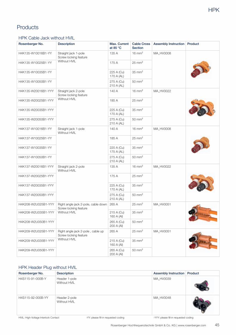
HPK Header Plug without HVIL
Rosenberger No. Description Assembly Instruction Product
H4S115-91-000B-Y Header 1-pole
Without HVIL
MA_HV0039
H4S115-92-000B-YY Header 2-pole
Without HVIL
MA_HV0048
HVIL: High-Voltage Interlock Contact -YY: please fi ll-in requested coding -YYY: please fi ll-in requested coding
Products
HPK Cable Jack without HVIL
Rosenberger No. Description Max. Current
at 85 °C
Cable Cross
Section
Assembly Instruction Product
H4K135-W10016B1-YY Straight jack 1-pole
Screw locking feature
Without HVIL
135 A 16 mm² MA_HV0008
H4K135-W10025B1-YY 175 A 25 mm²
H4K135-W10035B1-YY 225 A (Cu)
170 A (AL)
35 mm²
H4K135-W10050B1-YY 275 A (Cu)
210 A (AL)
50 mm²
H4K135-W20016B1-YYY Straight jack 2-pole
Screw locking feature
Without HVIL
140 A 16 mm² MA_HV0022
H4K135-W20025B1-YYY 185 A 25 mm²
H4K135-W20035B1-YYY 225 A (Cu)
170 A (AL)
35 mm²
H4K135-W20050B1-YYY 275 A (Cu)
210 A (AL)
50 mm²
H4K137-W10016B1-YY Straight jack 1-pole
Without HVIL
140 A 16 mm² MA_HV0008
H4K137-W10025B1-YY 185 A 25 mm²
H4K137-W10035B1-YY 220 A (Cu)
175 A (AL)
35 mm²
H4K137-W10050B1-YY 275 A (Cu)
210 A (AL)
50 mm²
H4K137-W20016B1-YYY Straight jack 2-pole
Without HVIL
135 A 16 mm² MA_HV0022
H4K137-W20025B1-YYY 175 A 25 mm²
H4K137-W20035B1-YYY 225 A (Cu)
170 A (AL)
35 mm²
H4K137-W20050B1-YYY 275 A (Cu)
210 A (AL)
50 mm²
H4K208-W2U025B1-YYY Right angle jack 2-pole, cable down
Screw locking feature
Without HVIL
265 A 25 mm² MA_HV0051
H4K208-W2U035B1-YYY 215 A (Cu)
160 A (Al)
35 mm²
H4K208-W2U050B1-YYY 265 A (Cu)
200 A (Al)
50 mm²
H4K209-W2U025B1-YYY Right angle jack 2-pole , cable up
Screw locking feature
Without HVIL
265 A 25 mm² MA_HV0051
H4K209-W2U035B1-YYY 215 A (Cu)
160 A (Al)
35 mm²
H4K209-W2U050B1-YYY 265 A (Cu)
200 A (Al)
50 mm²
HPK
46
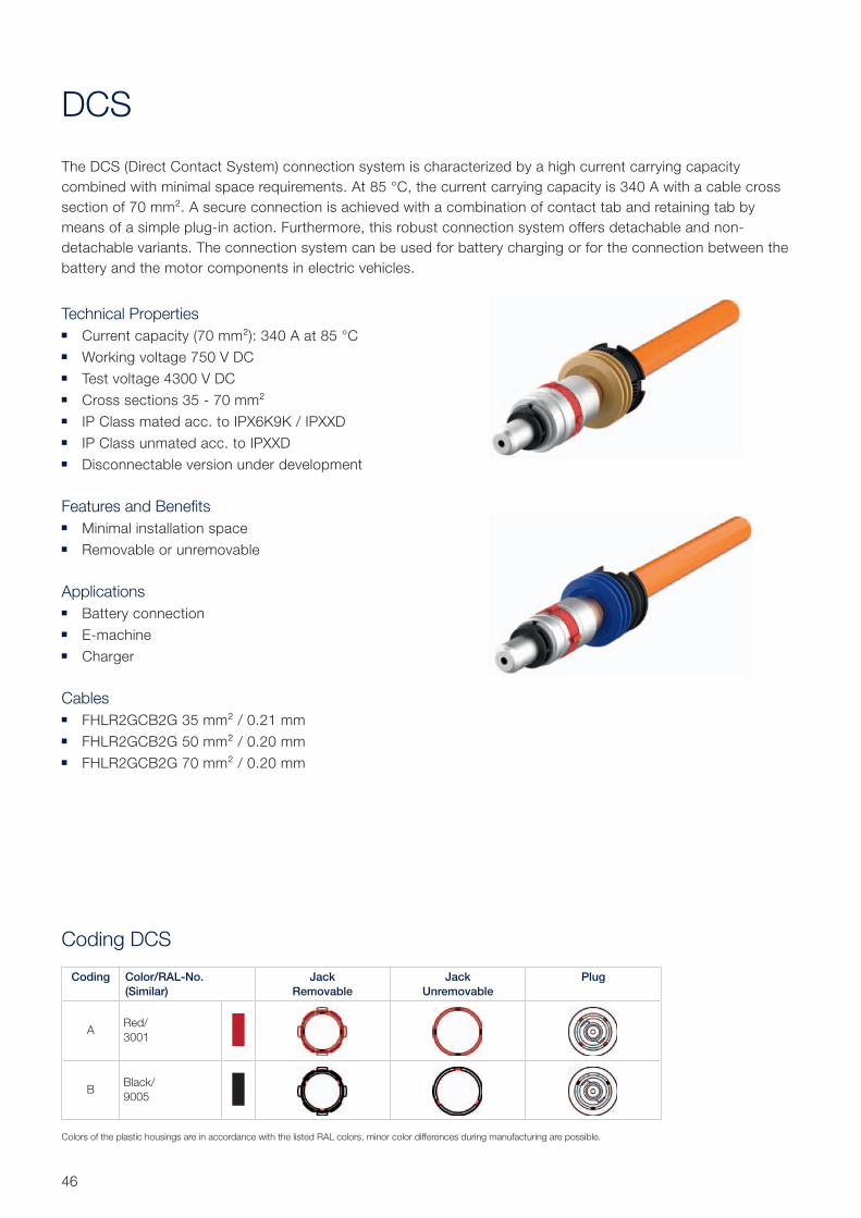
DCS
The DCS (Direct Contact System) connection system is characterized by a high current carrying capacity
combined with minimal space requirements. At 85 °C, the current carrying capacity is 340 A with a cable cross
section of 70 mm². A secure connection is achieved with a combination of contact tab and retaining tab by
means of a simple plug-in action . Furthermore, this robust connection system offers detachable and non-
detachable variants. The connection system can be used for battery charging or for the connection between the
battery and the motor components in electric vehicles.
Technical Properties ■ Current capacity (70 mm²): 340 A at 85 °C
■ Working voltage 750 V DC
■ Test voltage 4300 V DC
■ Cross sections 35 - 70 mm²
■ IP Class mated acc. to IPX6K9K / IPXXD
■ IP Class unmated acc. to IPXXD
■ Disconnectable version under development
Features and Benefits ■ Minimal installation space
■ Removable or unremovable
Applications ■ Battery connection
■ E-machine
■ Charger
Cables ■ FHLR2GCB2G 35 mm² / 0.21 mm
■ FHLR2GCB2G 50 mm² / 0.20 mm
■ FHLR2GCB2G 70 mm² / 0.20 mm
Coding DCS
Coding Color/RAL-No.
(Similar)
Jack
Removable
Jack
Unremovable
Plug
ARed/
3001
BBlack/
9005
Colors of the plastic housings are in accordance with the listed RAL colors, minor color differences during manufacturing are possible.
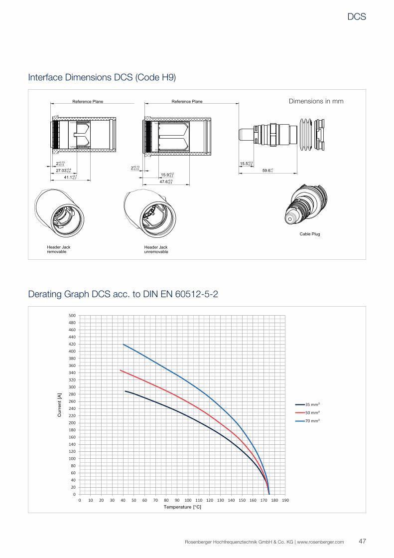
020406080
100120140160180200220240260280300320340360380400420440460480500
0 10 20 30 40 50 60 70 80 90 100 110 120 130 140 150 160 170 180 190
Cu
rre
nt
[A]
Temperature [°C]
35 mm²
50 mm²
70 mm²
59.6+1-1
15.5+0.5-0.5
41.1+0.7-0.7
27.03+0.4-0.4
2+0.13-0.13
C
15.9-0.2+0.2
47.6-0.5+0.5
2-0.13+0.13
47Rosenberger Hochfrequenztechnik GmbH & Co. KG | www.rosenberger.com
Interface Dimensions DCS (Code H9)
Derating Graph DCS acc. to DIN EN 60512-5-2
Dimensions in mm
DCS
48
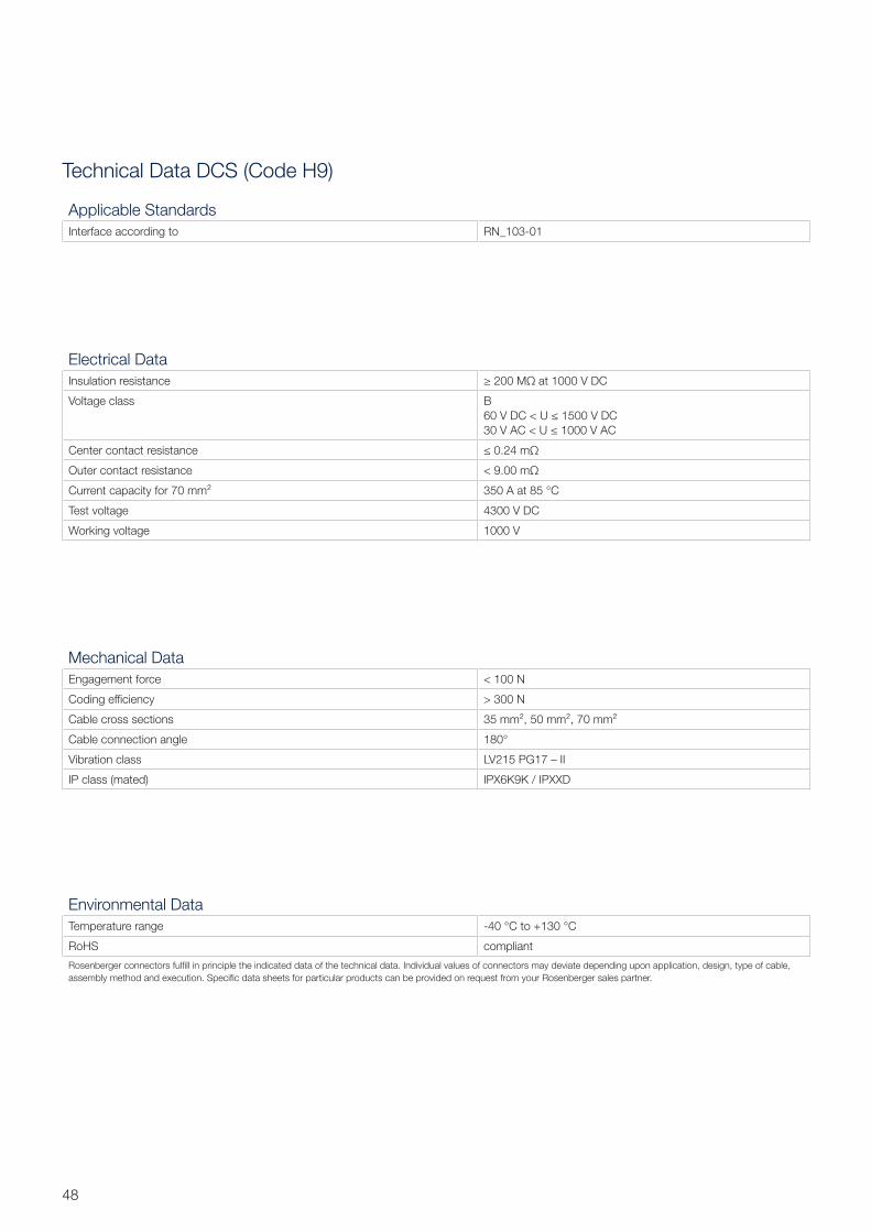
Technical Data DCS (Code H9)
Electrical Data
Insulation resistance ≥ 200 MΩ at 1000 V DC
Voltage class B
60 V DC < U ≤ 1500 V DC
30 V AC < U ≤ 1000 V AC
Center contact resistance ≤ 0.24 mΩ
Outer contact resistance < 9.00 mΩ
Current capacity for 70 mm² 350 A at 85 °C
Test voltage 4300 V DC
Working voltage 1000 V
Mechanical Data
Engagement force < 100 N
Coding effi ciency > 300 N
Cable cross sections 35 mm², 50 mm², 70 mm²
Cable connection angle 180°
Vibration class LV215 PG17 – II
IP class (mated) IPX6K9K / IPXXD
Environmental Data
Temperature range -40 °C to +130 °C
RoHS compliant
Rosenberger connectors fulfi ll in principle the indicated data of the technical data. Individual values of connectors may deviate depending upon application, design, type of cable,
assembly method and execution. Specifi c data sheets for particular products can be provided on request from your Rosenberger sales partner.
Applicable Standards
Interface according to RN_103-01
49Rosenberger Hochfrequenztechnik GmbH & Co. KG | www.rosenberger.com
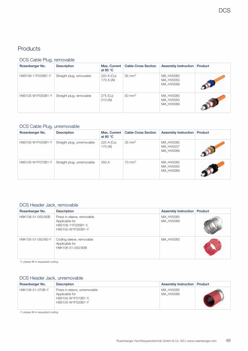
Products
DCS Cable Plug, removable
Rosenberger No. Description Max. Current
at 85 °C
Cable Cross Section Assembly Instruction Product
H9S109-11F035B1-Y Straight plug, removable 220 A (Cu)
170 A (Al)
35 mm² MA_HV0085
MA_HV0050
MA_HV0089
H9S105-W1F050B1-Y Straight plug, removable 275 (Cu)
210 (Al)
50 mm² MA_HV0085
MA_HV0050
MA_HV0089
DCS Cable Plug, unremovable
Rosenberger No. Description Max. Current
at 85 °C
Cable Cross Section Assembly Instruction Product
H9S105-W1F035B1-Y Straight plug, unremovable 225 A (Cu)
175 (Al)
35 mm² MA_HV0085
MA_HV0037
MA_HV0089
H9S105-W1F070B1-Y Straight plug, unremovable 350 A 70 mm² MA_HV0085
MA_HV0050
MA_HV0089
DCS Header Jack, removable
Rosenberger No. Description Assembly Instruction Product
H9K106-51-050/90B Press in sleeve, removable
Applicable for
H9S109-11F035B1-Y,
H9S105-W1F050B1-Y
MA_HV0085
MA_HV0089
H9K105-51-050/80-Y Coding sleeve, removable
Applicable for
H9K106-51-050/90B
MA_HV0083
-Y: please fi ll-in requested coding
DCS Header Jack, unremovable
Rosenberger No. Description Assembly Instruction Product
H9K106-51-070B-Y Press in sleeve, unremovable
Applicable for
H9S105-W1F070B1-Y,
H9S105-W1F035B1-Y
MA_HV0085
MA_HV0089
-Y: please fi ll-in requested coding
DCS
50
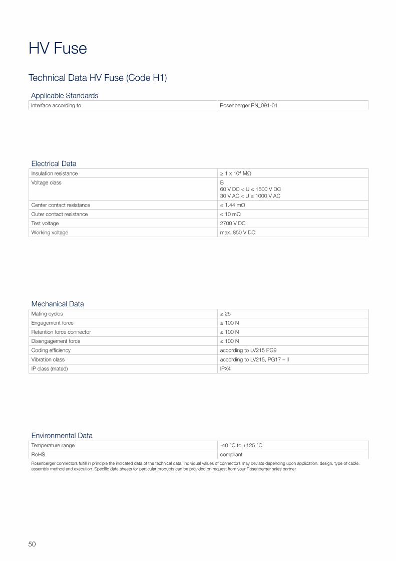
Technical Data HV Fuse (Code H1)
HV Fuse
Electrical Data
Insulation resistance ≥ 1 x 10⁴ MΩ
Voltage class B
60 V DC < U ≤ 1500 V DC
30 V AC < U ≤ 1000 V AC
Center contact resistance ≤ 1.44 mΩ
Outer contact resistance ≤ 10 mΩ
Test voltage 2700 V DC
Working voltage max. 850 V DC
Mechanical Data
Mating cycles ≥ 25
Engagement force ≤ 100 N
Retention force connector ≤ 100 N
Disengagement force ≤ 100 N
Coding effi ciency according to LV215 PG9
Vibration class according to LV215, PG17 – II
IP class (mated) IPX4
Environmental Data
Temperature range -40 °C to +125 °C
RoHS compliant
Rosenberger connectors fulfi ll in principle the indicated data of the technical data. Individual values of connectors may deviate depending upon application, design, type of cable,
assembly method and execution. Specifi c data sheets for particular products can be provided on request from your Rosenberger sales partner.
Applicable Standards
Interface according to Rosenberger RN_091-01
51Rosenberger Hochfrequenztechnik GmbH & Co. KG | www.rosenberger.com
Products
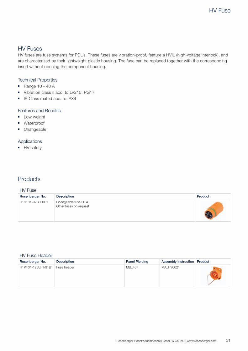
HV FusesHV fuses are fuse systems for PDUs. These fuses are vibration-proof, feature a HVIL (high-voltage interlock), and
are characterized by their lightweight plastic housing. The fuse can be replaced together with the corresponding
insert without opening the component housing.
Technical Properties ■ Range 10 - 40 A
■ Vibration class II acc. to LV215, PG17
■ IP Class mated acc. to IPX4
Features and Benefits ■ Low weight
■ Waterproof
■ Changeable
Applications ■ HV safety
HV Fuse
Rosenberger No. Description Product
H1S101-92SLF0B1 Changeable fuse 30 A
Other fuses on request
HV Fuse Header
Rosenberger No. Description Panel Piercing Assembly Instruction Product
H1K101-12SLF1/91B Fuse header MB_467 MA_HV0021
HV Fuse
52
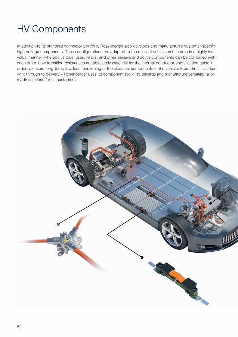
HV Components
In addition to its standard connector portfolio, Rosenberger also develops and manufactures customer-specific
high-voltage components. These configurations are adapted to the relevant vehicle architecture in a highly indi-
vidual manner, whereby various fuses, relays, and other passive and active components can be combined with
each other. Low transition resistances are absolutely essential for the internal conductor and shielded cable in
order to ensure long-term, low-loss functioning of the electrical components in the vehicle. From the initial idea
right through to delivery – Rosenberger uses its component toolkit to develop and manufacture versatile, tailor-
made solutions for its customers.
53Rosenberger Hochfrequenztechnik GmbH & Co. KG | www.rosenberger.com
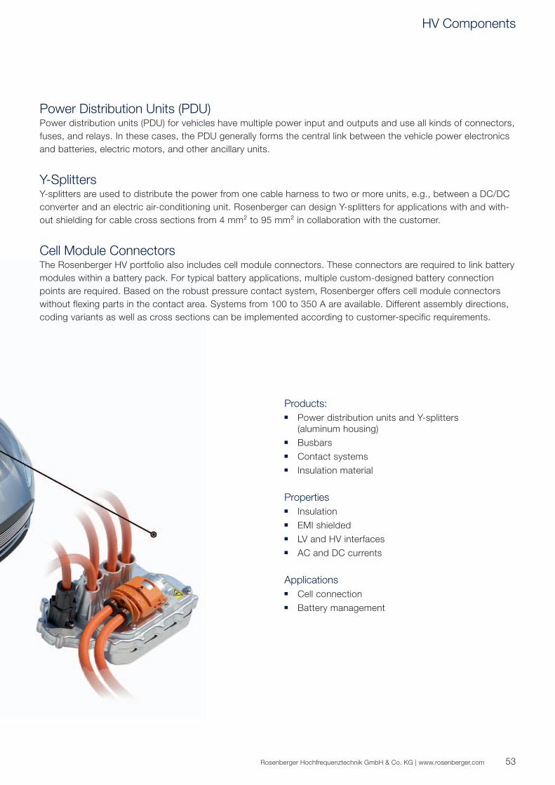
Power Distribution Units (PDU)Power distribution units (PDU) for vehicles have multiple power input and outputs and use all kinds of connectors,
fuses, and relays. In these cases, the PDU generally forms the central link between the vehicle power electronics
and batteries, electric motors, and other ancillary units.
Y-SplittersY-splitters are used to distribute the power from one cable harness to two or more units, e.g., between a DC/DC
converter and an electric air-conditioning unit. Rosenberger can design Y-splitters for applications with and with-
out shielding for cable cross sections from 4 mm² to 95 mm² in collaboration with the customer.
Cell Module ConnectorsThe Rosenberger HV portfolio also includes cell module connectors. These connectors are required to link battery
modules within a battery pack. For typical battery applications, multiple custom-designed battery connection
points are required. Based on the robust pressure contact system, Rosenberger offers cell module connectors
without flexing parts in the contact area. Systems from 100 to 350 A are available. Different assembly directions,
coding variants as well as cross sections can be implemented according to customer-specific requirements.
Products: ■ Power distribution units and Y-splitters
(aluminum housing)
■ Busbars
■ Contact systems
■ Insulation material
Properties ■ Insulation
■ EMI shielded
■ LV and HV interfaces
■ AC and DC currents
Applications ■ Cell connection
■ Battery management
HV Components
54
Coding LVR®120
LVR®120
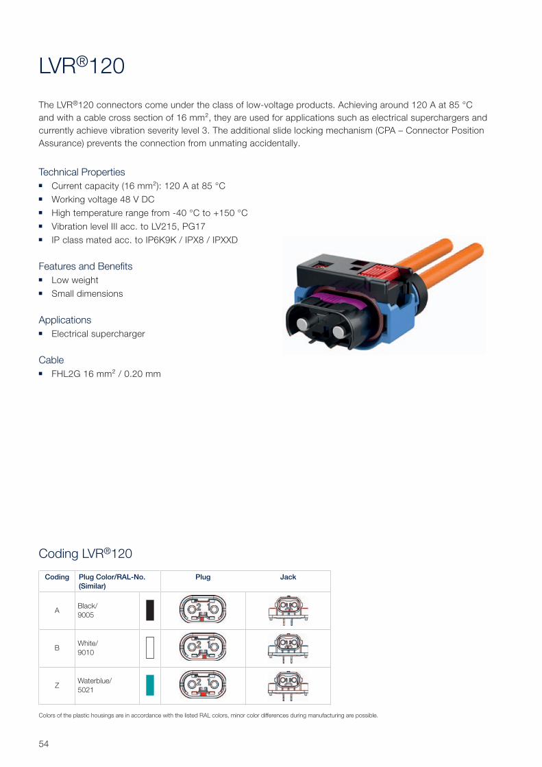
The LVR®120 connectors come under the class of low-voltage products. Achieving around 120 A at 85 °C
and with a cable cross section of 16 mm², they are used for applications such as electrical superchargers and
currently achieve vibration severity level 3. The additional slide locking mechanism (CPA – Connector Position
Assurance) prevents the connection from unmating accidentally.
Technical Properties ■ Current capacity (16 mm²): 120 A at 85 °C
■ Working voltage 48 V DC
■ High temperature range from -40 °C to +150 °C
■ Vibration level III acc. to LV215, PG17
■ IP class mated acc. to IP6K9K / IPX8 / IPXXD
Features and Benefits ■ Low weight
■ Small dimensions
Applications ■ Electrical supercharger
Cable ■ FHL2G 16 mm² / 0.20 mm
Coding Plug Color/RAL-No.
(Similar)
Plug Jack
ABlack/
9005
BWhite/
9010
ZWaterblue/
5021
Colors of the plastic housings are in accordance with the listed RAL colors, minor color differences during manufacturing are possible.
55Rosenberger Hochfrequenztechnik GmbH & Co. KG | www.rosenberger.com
0
10
20
30
40
50
60
70
80
90
100
110
120
130
140
150
160
0 10 20 30 40 50 60 70 80 90 100 110 120 130 140 150 160 170 180 190
Cu
rre
nt
[A]
Temperature [°C]
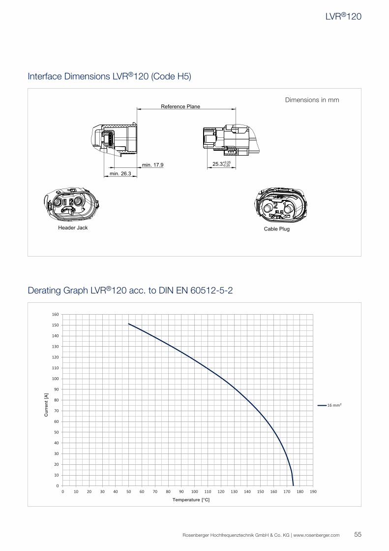
16 mm²
25.3+0.25-0.25min. 17.9
min. 26.3
R
C
Interface Dimensions LVR®120 (Code H5)
Derating Graph LVR®120 acc. to DIN EN 60512-5-2
Dimensions in mm
LVR®120
56
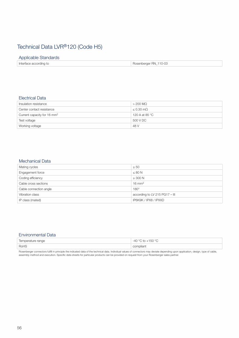
Technical Data LVR®120 (Code H5)
Electrical Data
Insulation resistance > 200 MΩ
Center contact resistance ≤ 0.30 mΩ
Current capacity for 16 mm2 120 A at 85 °C
Test voltage 500 V DC
Working voltage 48 V
Mechanical Data
Mating cycles ≥ 50
Engagement force ≤ 80 N
Coding effi ciency ≥ 300 N
Cable cross sections 16 mm2
Cable connection angle 180°
Vibration class according to LV 215 PG17 – III
IP class (mated) IP6K9K / IPX8 / IPXXD
Environmental Data
Temperature range -40 °C to +150 °C
RoHS compliant
Rosenberger connectors fulfi ll in principle the indicated data of the technical data. Individual values of connectors may deviate depending upon application, design, type of cable,
assembly method and execution. Specifi c data sheets for particular products can be provided on request from your Rosenberger sales partner.
Applicable Standards
Interface according to Rosenberger RN_110-03

57Rosenberger Hochfrequenztechnik GmbH & Co. KG | www.rosenberger.com
Products
LVR®120 Header Jack
Rosenberger No. Description Assembly Instruction Product
H5K202-92-000X1-Y Right angle jack
Header
Available on request
On request
-Y please fi ll in requested codiing
LVR®120 Cable Plug
Rosenberger No. Description Max. Current
at 85 °C
Cable Cross Section Assembly Instruction Product
H5S102-920016X1-Y Straight plug
Waterproof
Available on request
120 A 16 mm² On request
LVR®120
58
Rosenberger No.
170-099-00005 29
170-101-00000 44
H1K101-12SLF1/91B 51
H1S101-92SLF0B1 51
H2K102-W2A016B1-Y 29
H2K102-W2A025B1-Y 29
H2K102-W2A035B1-Y 29
H2S104-02-000B1-Y 29
H2S207-02-000B1-Y 29
H4K134-W10016B1-YY 44
H4K134-W10025B1-YY 44
H4K134-W10035B1-YY 44
H4K134-W10050B1-YY 44
H4K134-W20016B1-YYY 44
H4K134-W20025B1-YYY 44
H4K134-W20035B1-YYY 44
H4K134-W20050B1-YYY 44
H4K135-W10016B1-YY 45
H4K135-W10025B1-YY 45
H4K135-W10035B1-YY 45
H4K135-W10050B1-YY 45
H4K135-W20016B1-YYY 45
H4K135-W20025B1-YYY 45
H4K135-W20035B1-YYY 45
H4K135-W20050B1-YYY 45
H4K136-W10016B1-YY 44
H4K136-W10025B1-YY 44
H4K136-W10035B1-YY 44
H4K136-W10050B1-YY 44
H4K136-W20016B1-YYY 44
H4K136-W20025B1-YYY 44
H4K136-W20035B1-YYY 44
H4K136-W20050B1-YYY 44
H4K137-W10016B1-YY 45
H4K137-W10025B1-YY 45
H4K137-W10035B1-YY 45
H4K137-W10050B1-YY 45
H4K137-W20016B1-YYY 45
H4K137-W20025B1-YYY 45
H4K137-W20035B1-YYY 45
H4K137-W20050B1-YYY 45
H4K208-W2U025B1-YYY 45
H4K208-W2U035B1-YYY 45
H4K208-W2U050B1-YYY 45
H4K209-W2U025B1-YYY 45
H4K209-W2U035B1-YYY 45
H4K209-W2U050B1-YYY 45
H4K210-W2U050B1-YYY 44
H4S115-91-000B-Y 45
H4S115-91-H00B-Y 44
H4S115-92-000B-Y 45
H4S115-92-H00B-Y 44
H5K202-92-000X1-Y 57
H5S102-920016X1-Y 57
H6K105-12A006B-Y 25
H6K106-12A004B1-Y 25
H6K106-12A006B1-Y 25
H6K205-12A006B-Y 25
H6K206-12A004B1-Y 25
H6K206-12A006B1-Y 25
H6L106-5B-001B1-Y 25
H6L106-5C-001B1-Y 25
H9K105-51-050/80-Y 49
H9K106-51-050/90B 49
H9K106-51-070B-Y 49
H9S105-W1F035B1-Y 49
H9S105-W1F050B1-Y 49
H9S105-W1F070B1-Y 49
H9S109-11F035B1-Y 49
HAK203-W10035B1-Y 39
HAK203-W10070B1-Y 39
HAK203-W10095B1-Y 39
HAK203-W10120B1-Y 39
HAS103-21-000B1-Y 39
HAS105-21-000B1-Y 39
HKK203-W20070B1-Y 35
HKS105-22-070B1-Y 35
Rosenberger Hochfrequenztechnik GmbH & Co. KG | www.rosenberger.com
Status February 2018 – Technical modifications and errors excepted. Similar images.
59
Rosenberger Hochfrequenztechnik GmbH & Co. KG
Hauptstraße 1 | 83413 Fridolfi ng
P.O. Box 1260 | 84526 Tittmoning
Germany
Phone +49 8684 18-0
www.rosenberger.com
Certifi ed by IATF 16949 · DIN EN 9100 · ISO 9001 · ISO 14001
Order No.
pA 237240 · Info251HVCat
2000/2018
Rosenberger® is a registered trademark of Rosenberger Hochfrequenztechnik GmbH & Co. KG.
All rights reserved.
© Rosenberger 2018
Website
For more information refer to our website:
www.rosenberger.com/hv


![Sin título-1 · gplithwm 02430 gp cr2430 gp cr2430 gp urwum cr2430 super value —super super high voltage (4lr44] 476 a. high voltage high voltage voltage voltage](https://static.fdocuments.net/doc/165x107/5fc9a1e0f8d7c57bb3741c3c/sin-ttulo-1-gplithwm-02430-gp-cr2430-gp-cr2430-gp-urwum-cr2430-super-value-asuper.jpg)

