High Voltage Circuit Breakers 3AP ... · PDF file High Voltage Circuit Breakers 3AP Type ......
12
www.siemens.com/energy High Voltage Circuit Breakers 3AP Type 72.5 kV to 800 kV Answers for energy. s
Transcript of High Voltage Circuit Breakers 3AP ... · PDF file High Voltage Circuit Breakers 3AP Type ......
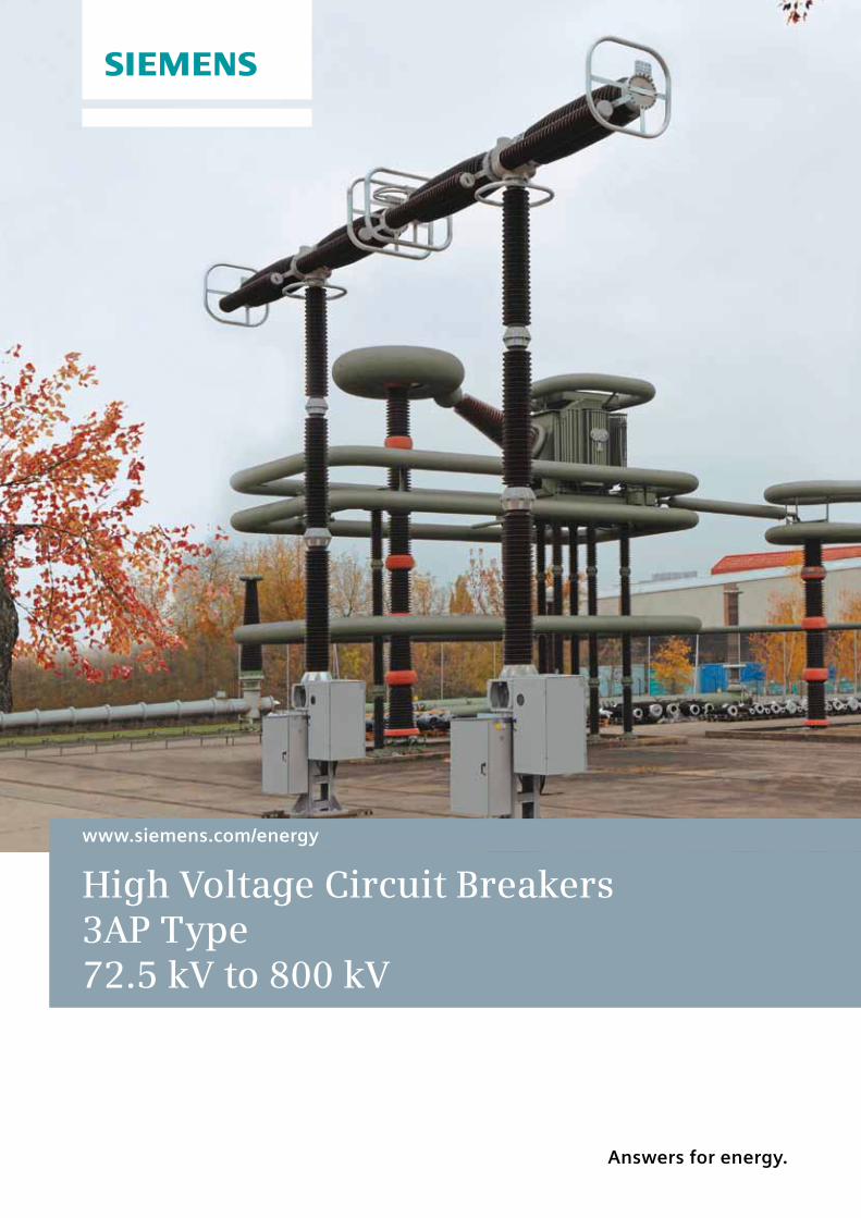
www.siemens.com/energy
High Voltage Circuit Breakers 3AP Type 72.5 kV to 800 kV
Answers for energy.
s
The 3AP High Voltage Circuit Breakers Available up to 800 kVDecades of our experience in high voltage switching technology go into the design and production of the 3AP circuit breakers which set an international trend. We are a powerful partner for our customers and a competent supplier of attractive products and solutions at competitive prices with the high standard of quality that Siemens is known for. We comply with our customers’ demands for reliability, safety and cost-effectiveness and serve them throughout the world. No matter what your application is, the 3AP circuit breakers provide the best solution for your requirements every time.
Our standard is reliability and safety at all times. The 3AP circuit breaker family is available for rated voltages from 72.5 kV up to 800 kV. The latest development of our well established circuit breakers completes our 3AP product range for rated voltages up to 800 kV. For the application of 420 kV to 800 kV the circuit breakers can be equipped
with optional closing resistors. The circuit breakers feature approved technology and ensures efficient operation. Based on our well proven modular design, we manufacture all of the core components ourselves, which include the stored-energy spring mechanism and the arc-assisted interrupter unit.
More than 90,000 nos. 3AP-circuit breakers have been delivered to over 140 countries around the world in all climatic areas, proving on a daily basis the value and the reliability of the 3AP high voltage switchgear. The 3AP high voltage circuit breaker operates safely and is capable of withstanding high mechanical loads. Particularly strong porcelain insulators and a circuit breaker design optimized by using the latest mathematical techniques, give it very high seismic stability whilst in operation enabling it to perform to its full potential during its entire service life.
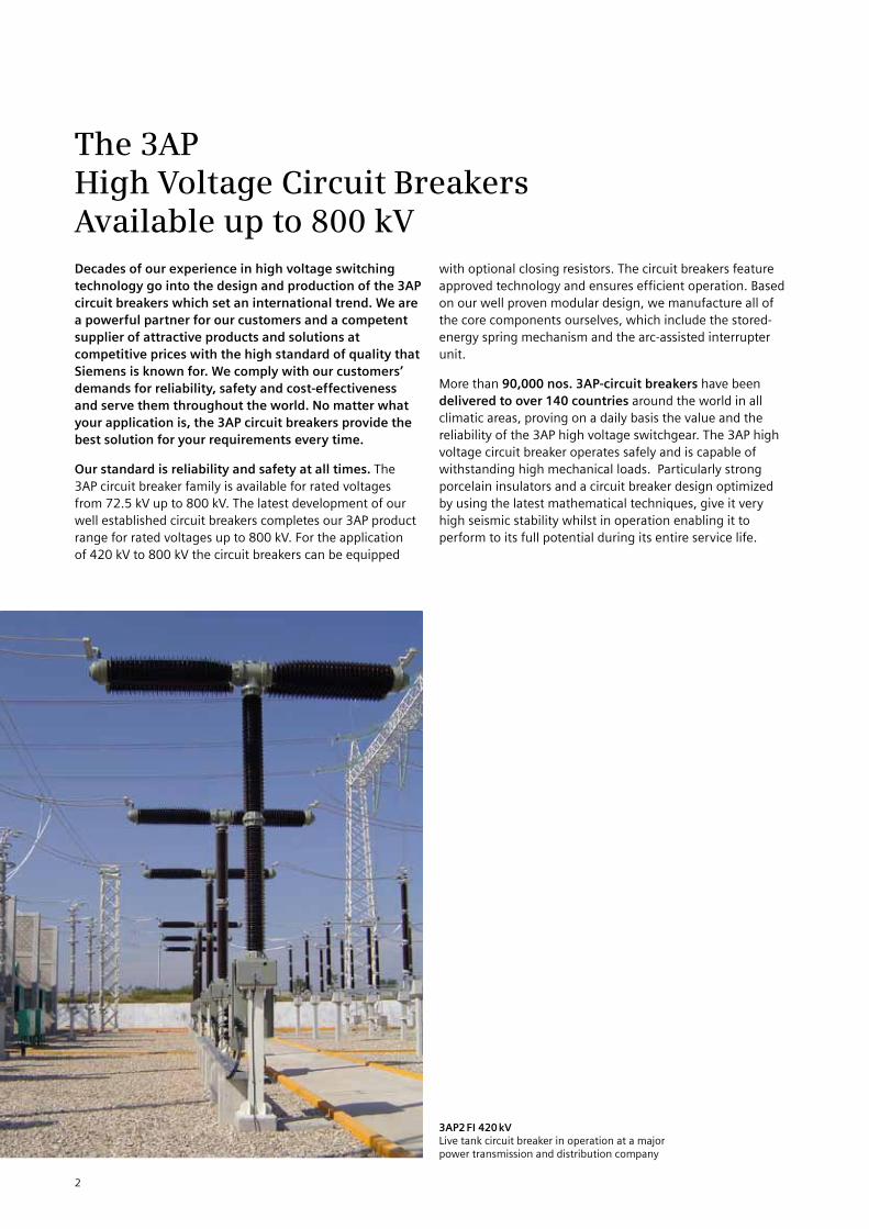
3AP2 FI 420 kVLive tank circuit breaker in operation at a major power transmission and distribution company
2
With High Voltage Circuit Breakers from Siemens you are always on the economically safe sideGreat demands for highest quality. Our quality management system, certified in accordance with DIN EN ISO 9001, confirms that our quality always remains at the same high level. We carry out regular management reviews, internal audits in every department and the continuous development and maintenance of documentation for all processes. Most modern manufacturing technologies and investments in our worldwide production sites, assure reliable and long-lasting products and process quality according to Siemens’ well-proven high standards.
The high quality, as well as excellent operating experience, is inherited by the 3AP series. The result is very high SF
6
tightness of our switchgear: The SF6 leakage rate is less
than 0.5% per year. This not only increases reliability and decreases operating costs as a result of long maintenance
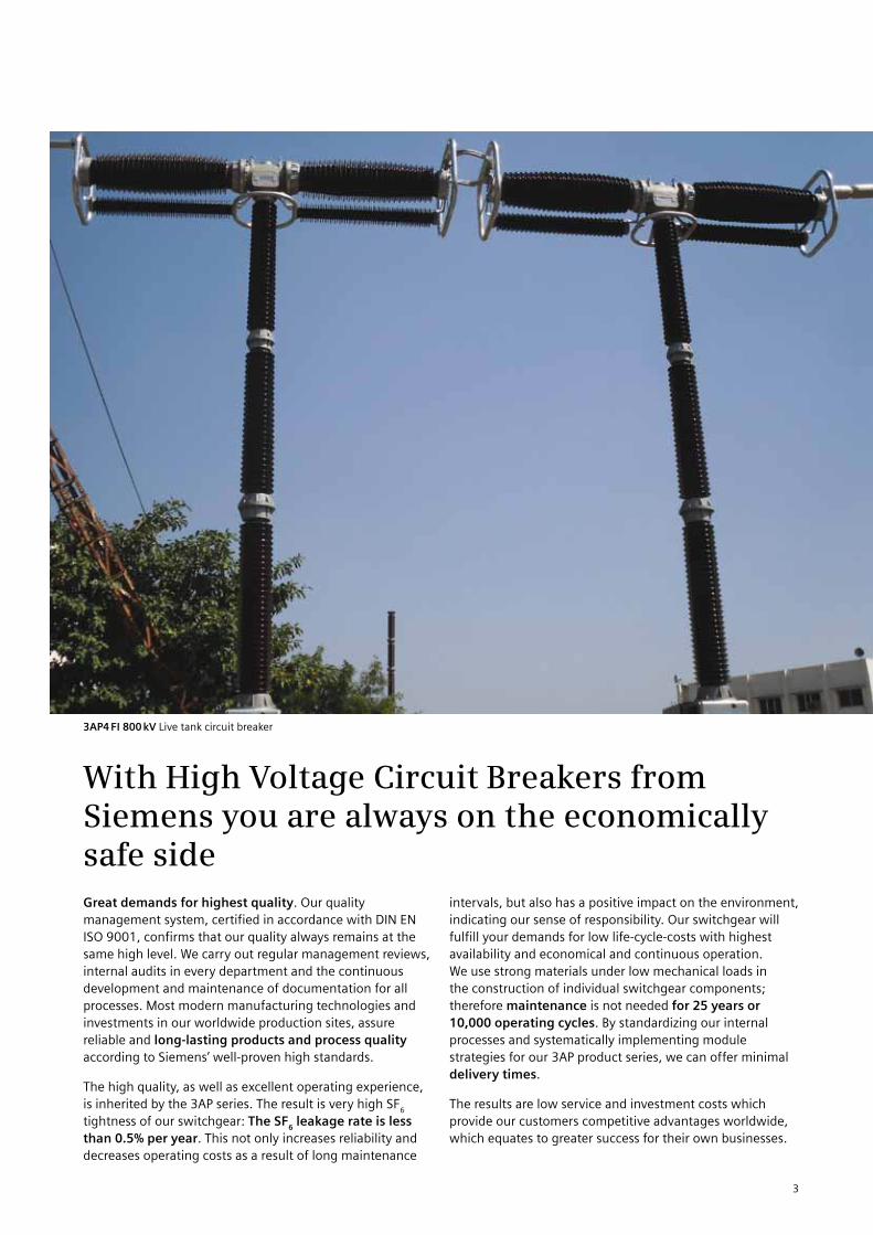
3AP4 FI 800 kV Live tank circuit breaker
intervals, but also has a positive impact on the environment, indicating our sense of responsibility. Our switchgear will fulfill your demands for low life-cycle-costs with highest availability and economical and continuous operation. We use strong materials under low mechanical loads in the construction of individual switchgear components; therefore maintenance is not needed for 25 years or 10,000 operating cycles. By standardizing our internal processes and systematically implementing module strategies for our 3AP product series, we can offer minimal delivery times.
The results are low service and investment costs which provide our customers competitive advantages worldwide, which equates to greater success for their own businesses.
3
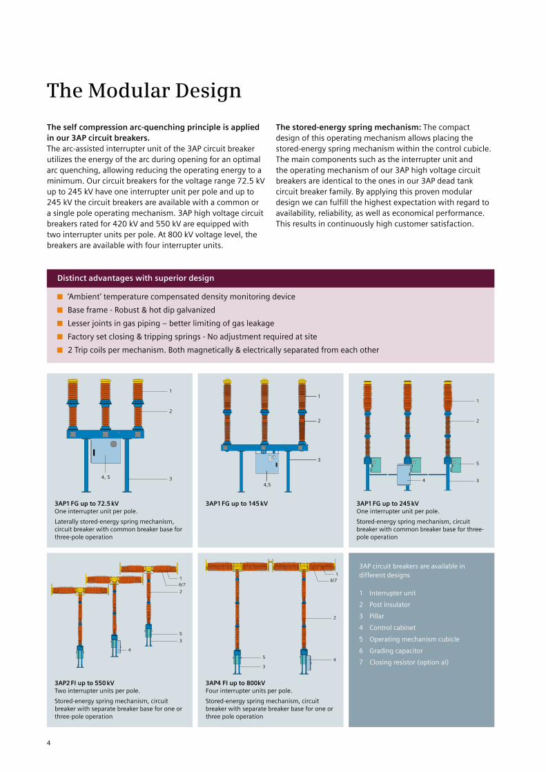
3AP circuit breakers are available in different designs
1 Interrupter unit
2 Post insulator
3 Pillar
4 Control cabinet
5 Operating mechanism cubicle
6 Grading capacitor
7 Closing resistor (option al)
The Modular Design
The self compression arc-quenching principle is applied in our 3AP circuit breakers. The arc-assisted interrupter unit of the 3AP circuit breaker utilizes the energy of the arc during opening for an optimal arc quenching, allowing reducing the operating energy to a minimum. Our circuit breakers for the voltage range 72.5 kV up to 245 kV have one interrupter unit per pole and up to 245 kV the circuit breakers are available with a common or a single pole operating mechanism. 3AP high voltage circuit breakers rated for 420 kV and 550 kV are equipped with two interrupter units per pole. At 800 kV voltage level, the breakers are available with four interrupter units.
The stored-energy spring mechanism: The compact design of this operating mechanism allows placing the stored-energy spring mechanism within the control cubicle. The main components such as the interrupter unit and the operating mechanism of our 3AP high voltage circuit breakers are identical to the ones in our 3AP dead tank circuit breaker family. By applying this proven modular design we can fulfill the highest expectation with regard to availability, reliability, as well as economical performance. This results in continuously high customer satisfaction.
3AP1 FG up to 72.5 kVOne interrupter unit per pole.
Laterally stored-energy spring mechanism, circuit breaker with common breaker base for three-pole operation
4,5
3
2
11
2
5
34
1
2
34, 5
1
2
5
3
4
6/7
1
2
45
3
6/7
Distinct advantages with superior design
‘Ambient’ temperature compensated density monitoring device
Base frame - Robust & hot dip galvanized
Lesser joints in gas piping – better limiting of gas leakage
Factory set closing & tripping springs - No adjustment required at site
2 Trip coils per mechanism. Both magnetically & electrically separated from each other
3AP1 FG up to 145 kV
3AP1 FG up to 245 kVOne interrupter unit per pole.
Stored-energy spring mechanism, circuit breaker with common breaker base for three-pole operation
3AP2 FI up to 550 kVTwo interrupter units per pole.
Stored-energy spring mechanism, circuit breaker with separate breaker base for one or three-pole operation
3AP4 FI up to 800kVFour interrupter units per pole.
Stored-energy spring mechanism, circuit breaker with separate breaker base for one or three pole operation
4
The Control
The control system includes all the secondary components required for operating the circuit breaker, most of them are located in the control cabinet. The control, tripping, motor and heating power supplies are, to a great extend, selectable. Depending on customer requirements, two standard control variants are available.
Basic variantThe basic variant includes all control and monitoring elements that are needed for operation of the circuit breaker. In addition to the elementary actuation functions, it includes:
Total 20 NO + 19 NC Auxiliary switch contacts
4 wiper contact Switching operation counter Local actuator
Compact variantIn addition to the basic variant, this variant includes:-
Spring monitoring by motor run time monitoring Heating monitoring
Light and socket with a common circuit breaker
MCB for AC/DC protection, Motor protection
MCB for heater protection
Special featuresAbove and beyond these two standard variants, a great number of further components and options are at our customers’ disposal. Every control configuration of a circuit breaker can therefore be designed individually. All control components have been type-tested for use on our circuit breakers and are all located in a weatherproof cubicle (IP 55 degree of protection). They are resistant to switching vibrations, and meet the requirements for electromagnetic compatibility (EMC).
The circuit breaker documentation includes the wiring diagram of the control configuration. This diagram comprises the following documents:
General Arrangement diagram Circuit diagram Technical data equipment part list Connection diagram
The circuit diagram documentation is in English.
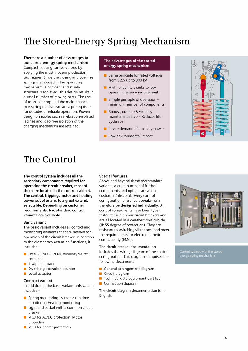
The Stored-Energy Spring Mechanism
There are a number of advantages to our stored-energy spring mechanismCompact housing can be utilized by applying the most modern production techniques. Since the closing and opening springs are housed in the operating mechanism, a compact and sturdy structure is achieved. This design results in a small number of moving parts. The use of roller bearings and the maintenance-free spring mechanism are a prerequisite for decades of reliable operation. Proven design principles such as vibration-isolated latches and load-free isolation of the charging mechanism are retained.
The advantages of the stored-energy spring mechanism:
Same principle for rated voltages from 72.5 up to 800 kV
High reliability thanks to low operating energy requirement
Simple principle of operation – minimum number of components
Robust, durable & virtually maintenance free – Reduces life cycle cost
Lesser demand of auxiliary power
Low environmental impact
Control cabinet with the stored-energy spring mechanism
5
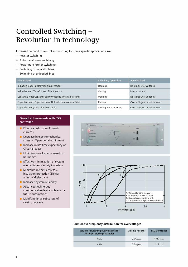
Controlled Switching – Revolution in technologyIncreased demand of controlled switching for some specific applications like
– Reactor switching
– Auto-transformer switching
– Power transformer switching
– Switching of capacitor bank
– Switching of unloaded lines
Kind of load Switching Operation Avoided load
Inductive load; Transformer; Shunt reactor Opening Re-strike; Over voltages
Inductive load; Transformer; Shunt reactor Closing Inrush current
Capacitive load; Capacitor bank; Unloaded lines/cables; Filter Opening Re-strike; Over voltages
Capacitive load; Capacitor bank; Unloaded lines/cables; Filter Closing Over voltages; Inrush current
Capacitive load; Unloaded lines/cables Closing; Auto-reclosing Over voltages; Inrush current
0
20
40
60
80
100
1 1,5 2 2,5 3
overvoltage [p.u.]
cfd
[%]
ABCD
0
20
40
60
80
100
1 1,5 2 2,5 3
overvoltage [p.u.]
cfd
[%]
ABCD
A. Without limiting measures
B. Using surge arrestors, only
C. Using closing resistors, only
D. Controlled closing with PSD controller
Cumulative frequency distribution for overvoltages
Value for switching overvoltages for different closing strategies
Closing Resistor PSD Controller
95% 2.05 p.u. 1.95 p.u.
99% 2.38 p.u. 2.13 p.u.
Overall achievements with PSD controller
Effective reduction of inrush currents
Decrease in electromechanical stress on Operational equipment
Increase in life time expectancy of Circuit Breaker
Minimization of stress caused of harmonics
Effective minimization of system over voltages = safety to system
Minimum dielectric stress = insulation protection (Slower aging of dielectrics)
Increased system reliability
Advanced technology communicable device = Ready for future automations
Multifunctional substitute of closing resistors
6
Quality Right from the StartDevelopmentThe foundation for the quality of Siemens high voltage circuit breakers is laid down right from the beginning of the development of a new product. Switching performance, high voltage stability and performance under mechanical loads (wind and short circuits) and during an earthquake are simulated and optimized in the outline design phase using computer- aided calculations.
The use of common parts and assembled units in a large number of breaker types such as live tank, dead tank, as well as in the GIS means the production of a large number of the same type of main components. Steady and regular quantities of produced units allow a continuous production process and ensure the highest quality standards. Statistic quality control is based on large quantities. This results in a higher achieved validity.
All 3AP circuit breakers can be used in earthquake areas up to 0.5 g without additional fittings.
Testing laboratoriesOur state-of-the-art circuit breaker plant has the most modern testing facilities:
High voltage testing lab Mechanical testing lab Temperature rise testing laboratory
Type testing of all our 3AP type Circuit Breakers has been carried out at globally recognized premium test laboratories like PEHLA (Germany), CPRI (India) & ERDA (India). The 3AP circuit breakers are fully type tested in accordance with the latest IEC 62271-100.
Routine testingThe main components of the circuit breakers are subjected to complete pre-acceptance testing before assembly. Based on this quality level, it is possible to confirm a leakage rate of less than 0.5% per year for the circuit breaker. Each circuit breaker is completely assembled in the test bay. The product specific inputs for computer-assisted routine testing are imported from the order processing tools. This ensures that in addition to the standard test procedure, the fulfillment of every customer requirement is checked before delivery.
Routine testing is performed in accordance with the latest IEC standards and it includes at least the following operations and measurements performed on each & every breaker:
Mechanical operations test Switching time determination – Speed travel
characteristics Gas leakage test Testing of control circuits in accordance with the circuit
diagram Contact resistance measurement High voltage tests
7
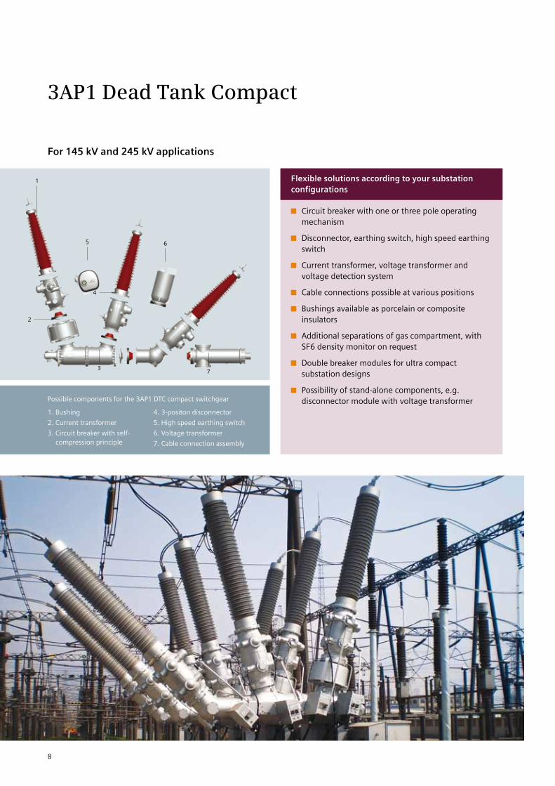
3AP1 Dead Tank Compact
For 145 kV and 245 kV applications
1. Bushing
2. Current transformer
3. Circuit breaker with self-compression principle
4. 3-positon disconnector
5. High speed earthing switch
6. Voltage transformer
7. Cable connection assembly
Possible components for the 3AP1 DTC compact switchgear
Flexible solutions according to your substation configurations
Circuit breaker with one or three pole operating mechanism
Disconnector, earthing switch, high speed earthing switch
Current transformer, voltage transformer and voltage detection system
Cable connections possible at various positions
Bushings available as porcelain or composite insulators
Additional separations of gas compartment, with SF6 density monitor on request
Double breaker modules for ultra compact substation designs
Possibility of stand-alone components, e.g. disconnector module with voltage transformer
2
4
73
65
1
8

The hybrid concept, on which the 3AP1 Dead Tank Compact (DTC) is based on, combines SF6-encapsulated components and air-insulated devices. The application of gas insulated components increases availability of switchgear. According to CIGRE analyses, gas insulated components are four times more reliable than air insulated components. Furthermore, safety can be enhanced by separating gas compartments, e.g. between circuit breaker and disconnector.
The DTC circuit breaker is a compact arrangement of several functions needed in a substation. The elements of this Siemens Compact Switchgear is a dead tank circuit breaker, fitted with one or two current transformers, one or more disconnectors, earthing switches and bushings as applicable for connection to the bus bar system. And of course, based on our modular design, the core components have been adopted from our high voltage circuit breakers, disconnectors and GIS product family. Due to the compact design and the flexible use of predefined modules, different layouts can be realized with a minimum of engineering effort.
The 3AP1 DTC offers you:
Proven SF6- and air-insulated components that can be combined in different, new ways
Optimized investments according to requirements of your individual substation layout
Gas insulated components ensure highest availability at minimum maintenance effort
Flexibility in confined spaces and extreme environmental conditions, e.g. low temperature applications
Benefit from the hybrid idea!
The level of encapsulation and the design of the DTC module can be defined in accordance with the requirements of the individual substation layout and the system operator’s project budget. This leads to optimized investments and greater success for our customers’ businesses.
9
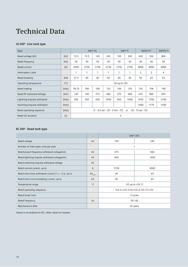
Technical Data
A) 3AP - Live tank type
Type 3AP1 FG 3AP1 FI 3AP2/3 FI 3AP4/5 FI
Rated voltage (kV) [kV] 72.5 72.5 145 245 145 245 420 550 800
Rated frequency [Hz] 50 50 50 50 50 50 50 50 50
Rated current [A] 2500 3150 3150 3150 3150 3150 4000 4000 4000
Interrupters / pole 1 1 1 1 1 1 2 2 4
Rated breaking [kA] 31.5 40 40 50 40 50 50 63 63
Operating temperature [°C] -30 up to +55
Rated making [kAp] 78.75 100 100 125 100 125 125 158 158
Rated PF withstand Voltage [kVr] 140 140 275 460 275 460 610 800 870
Lightning Impulse withstand [kVp] 350 350 650 1050 650 1050 1425 1550 2100
Switching Impulse withstand [kVp] 1050 1175 1550
Rated operating sequence [kAp] O - 0.3 sec - CO - 3 min - CO or CO - 15 sec - CO
Rated S/C duration [s] 3
B) 3AP - Dead tank type
3AP1 DTC
Rated voltage kV 145 245
Number of interrupter units per pole 1
Rated power-frequency withstand voltage/min kV 275 460
Rated lightning impulse withstand voltage/min kV 650 1050
Rated switching impulse withstand voltage kV
Rated normal current, up to A 3150 4000
Rated short-time withstand current (1 s – 3 s), up to kA(ms)
40 63
Rated short-circuit breaking current, up to kA 40 63
Temperature range °C -55 up to +55 °C
Rated operating sequence 0-0.3 s-CO-3 min-CO or CO-15 s-CO
Rated break time 3 cycles
Rated frequency Hz 50 / 60
Maintenance after 25 years
Values in accordance to IEC, other values on request
10

Notes
11
Siemens Ltd.Energy SectorEnergy Transmission - High Voltage BreakersE-76, Waluj MIDC, Aurangabad - 431 136Maharashtra, INDIAFax: +91 240 255 4701E-mail: [email protected]
www.siemens.com/energy
ENE-20-001-001
Product upgradation is a continuous process. Hence, data in this catalog is subject to change without prior notice. For the latest information, please get in touch with our Sales Offices.
A worldwide 24 hours service is available, which immediately sends out service personnel and/or delivers spare parts as needed.
Customer Support Center:-
Toll free Phone no. in India: 1800 2667 480 Email: [email protected]