High Temp Creep-fatigue Crit for Fusion Eurofer 97
40
7/30/2019 High Temp Creep-fatigue Crit for Fusion Eurofer 97 http://slidepdf.com/reader/full/high-temp-creep-fatigue-crit-for-fusion-eurofer-97 1/40 Forschungszentrum Karlsruhe in der Helmholtz-Gemeinschaft Wissenschaftliche Berichte FZKA 7309 High Temperature Creep-Fatigue Structural Design Criteria for Fusion Components Built from EUROFER 97 Final Report: TW2-TTMS-005b, D1 TW5-TTMS-005, D7 J . Aktaa, M. Weick, M. Walter Institut für Materialforschung Programm Kernfusion Association Forschungszentrum Karlsruhe/EURATOM Au gu st 2007
Transcript of High Temp Creep-fatigue Crit for Fusion Eurofer 97
7/30/2019 High Temp Creep-fatigue Crit for Fusion Eurofer 97
http://slidepdf.com/reader/full/high-temp-creep-fatigue-crit-for-fusion-eurofer-97 1/40
Forschungszentrum Karlsruhe
in der Helmholtz-Gemeinschaft
Wissenschaftliche BerichteFZKA 7309
High TemperatureCreep-Fatigue Structural
Design Criteria for FusionComponents Built fromEUROFER 97Final Report:TW2-TTMS-005b, D1TW5-TTMS-005, D7
J. Aktaa, M. Weick, M. Walter
Institut für MaterialforschungProgramm Kernfusion Association Forschungszentrum Karlsruhe/EURATOM
August 2007

7/30/2019 High Temp Creep-fatigue Crit for Fusion Eurofer 97
http://slidepdf.com/reader/full/high-temp-creep-fatigue-crit-for-fusion-eurofer-97 2/40
7/30/2019 High Temp Creep-fatigue Crit for Fusion Eurofer 97
http://slidepdf.com/reader/full/high-temp-creep-fatigue-crit-for-fusion-eurofer-97 3/40
Forschungszentrum Karlsruhe
in der Helmholtz-Gemeinschaft
Wissenschaftliche Berichte
Forschungszentrum Karlsruhe GmbH, Karlsruhe
2007
FZKA 7309
High temperature creep-fatigue structural design
criteria for fusion components built from
EUROFER 97
Final Report:
TW2-TTMS-005b, D1
TW5-TTMS-005, D7
J . Aktaa, M. Weick, M. Walter
Association Forschungszentrum Karlsruhe/EURATOM
Programm Kernfusion
Institut für Materialforschung

7/30/2019 High Temp Creep-fatigue Crit for Fusion Eurofer 97
http://slidepdf.com/reader/full/high-temp-creep-fatigue-crit-for-fusion-eurofer-97 4/40
Für diesen Bericht behalten wir uns alle Rechte vor
Forschungszentrum Karlsruhe GmbH
Postfach 3640, 76021 Karlsruhe
Mitglied der Hermann von Helmholtz-Gemeinschaft
Deutscher Forschungszentren (HGF)
ISSN 0947-8620
urn:nbn:de:0005-073093
7/30/2019 High Temp Creep-fatigue Crit for Fusion Eurofer 97
http://slidepdf.com/reader/full/high-temp-creep-fatigue-crit-for-fusion-eurofer-97 5/40
iii
Hochtemperatur-Auslegungsregeln für Kriech-Ermüdung von Fusionskomponenten
aus EUROFER 97
Zusammenfassung
Die Hochtemperaturregeln für Kriech-Ermüdung der bereits etablierten ASME- und RCC-
MR-Auslegungscodes wurden betrachtet, analysiert und für die Bewertung von aus EURO-
FER 97 gefertigten Bauteilen angepasst. Für die Verifikation der angepassten Regeln wur-
den isotherme Zwei-Stufen-Ermüdungs-, thermo-mechanische Ermüdungs- und isotherme
mehrachsige Ermüdungsversuche durchgeführt und ausgewertet. Dabei wurde festgestellt,
dass die herkömlichen Auslegungsregeln nicht ohne weiteres anwendbar auf EUROFER 97
sind. Sie können die beobachtete starke Lebensdauerabnahme unter thermo-mechanischen
und mehrachsigen zyklischen Belastungen nicht erfassen, was hauptsächlich auf das unter-
schiedliche zyklische Entfestigungsverhalten unter diesen Belastungen im Vergleich zur iso-
thermen einachsigen Belastung zurückgeführt wird. Aus diesem Grund wurden die Regeln
durch die Herleitung neuer Ermüdungs-Auslegungskurven unter Berücksichtigung des zykli-
schen Entfestigungseinflusses modifiziert. Dabei wurde ein Schädigungsmodell verwendet,
das zuletzt zur Beschreibung der Degradation von EUROFER 97 unter Kriech-
Ermüdungsbelastungen entwickelt wurde. Auch wenn die verbesserten Regeln hinreichend
bei der Betrachtung der Verifikationsversuche waren, werden weitere Verifikationen empfoh-
len.
7/30/2019 High Temp Creep-fatigue Crit for Fusion Eurofer 97
http://slidepdf.com/reader/full/high-temp-creep-fatigue-crit-for-fusion-eurofer-97 6/40
iv
Abstract
High temperature creep-fatigue design rules already established in the ASME and RCC-MR
codes have been reviewed, analysed and reformulated for the assessment of components
built from EUROFER 97. For the verification of the rules isothermal two-steps fatigue, ther-
mo-mechanical fatigue and isothermal multiaxial fatigue tests have been performed and
evaluated. It has been found that the conventional design rules are not straightforward appli-
cable for EUROFER 97. They can not cover the strong lifetime reduction observed under
thermo-mechanical and multiaxial cyclic loadings which has been mainly attributed to the
different cyclic softening behaviour under these loading modes in comparison to isothermal
uniaxial loading. Hence, the rules have been modified by deriving new fatigue design curves
taking into account cyclic softening effects. Thereby, a damage model recently developed to
describe the deterioration of EUROFER 97 under creep fatigue loading has been used. Even
the improved rules have been sufficiently conservative when considering the verification tests
performed further verifications are recommended.
7/30/2019 High Temp Creep-fatigue Crit for Fusion Eurofer 97
http://slidepdf.com/reader/full/high-temp-creep-fatigue-crit-for-fusion-eurofer-97 7/40
v
TABLE OF CONTENTS
1 Introduction........................................................................................................................1
2 Creep-fatigue evaluation rules ..........................................................................................1 2.1 Damage equation.........................................................................................................1
2.2 Equivalent strain range.................................................................................................3
2.2.1 ASME-Code...........................................................................................................3
2.2.2 RCC-MR Code.......................................................................................................5
2.2.3 Comparison between ASME and RCC-MR Codes................................................5
2.3 Design fatigue curves ...................................................................................................6
2.4 Stress-to-rupture curves ...............................................................................................6
2.5 Allowable total creep-fatigue damage...........................................................................6
3 Application of the rules to EUROFER 97..........................................................................7 4 Verification experiments..................................................................................................10
4.1 Isothermal two steps LCF experiments ......................................................................10
4.1.1 Experimental........................................................................................................11
4.1.2 Results.................................................................................................................12
4.2 Thermomechanical fatigue experiments.....................................................................14
4.2.1 Experimental........................................................................................................14
4.2.2 Results.................................................................................................................14
4.3 Isothermal multi-axial fatigue experiments .................................................................17
4.3.1 Experimental details ............................................................................................17
4.3.2 Experimental results ............................................................................................20
5 Improved rules for EUROFER 97....................................................................................25
6 Summary and outlook .....................................................................................................29
7 Acknowledgment.............................................................................................................30
8 References......................................................................................................................30

7/30/2019 High Temp Creep-fatigue Crit for Fusion Eurofer 97
http://slidepdf.com/reader/full/high-temp-creep-fatigue-crit-for-fusion-eurofer-97 8/40
7/30/2019 High Temp Creep-fatigue Crit for Fusion Eurofer 97
http://slidepdf.com/reader/full/high-temp-creep-fatigue-crit-for-fusion-eurofer-97 9/40
Introduction
1
1 Introduction
The reduced activation ferritic martensitic (RAFM) steel EUROFER 97 developed recently in
the framework of EURATOM Fusion Technology programme is a potential candidate as a
structural material for in-vessel components of future fusion power plants [1]. During planed
operation structural materials of in-vessel plasma facing components, Blanket and Divertor,
are subjected to cyclic thermo-mechanical loading and high irradiation doses which yield
different types of lifetime limiting failure mechanisms: ratchetting, creep, fatigue and radiation
induced loss in ductility and toughness.
Within our activities in the EFDA Technology Work programme with the reference TTMS-005
“Rules for Design, Fabrication and Inspection” structural design criteria for components built
from EUROFER 97 will be developed and qualified. Our investigations are focused on high
temperature rules, particularly those for preventing creep, fatigue and creep/fatigue interac-
tion, not yet considered and implemented in the current ITER Structural Design Criteria for
In-Vessel Components (SDC-IC) [2]. Therefore we started evaluating the high temperature
rules of the current design codes well established for nuclear applications: ASME Boiler and
Pressure Vessels Code, Code Case N-47 and the French RCC-MR code, RB 3200 and
RC 3200. For the evaluation various verification experiments have been planed and per-
formed. The aim of the evaluation is to determine whether the well established rules provide
a sufficient safety margin when they are applied to EUROFER 97 structures and if they do so
how much their conservatism amounts. In parallel a coupled deformation damage model for
creep-fatigue interaction has been developed [3] which should provide a best estimated life-
time prediction and thus help in removing the unnecessary conservatism the design rules
might have.
In this report, a brief overview about the creep-fatigue evaluation rules of the ASME-BPV and
RCC-MR codes and about how they can be applied to EUROFER 97 structures will be firstly
given. Thereafter the verification experiments performed are described and their results are
presented and discussed particularly from point of view of the conventional design rules.
Based on this discussion and the knowledge gathered so far recommendations for new de-
sign rules and further verification experiments are concluded.
2 Creep-fatigue evaluation rules
In the ASME-BPV (Code Case N-47, T-1400) and RCC-MR (RB 3262.12) codes similar rules
are used for design against creep, fatigue and creep-fatigue interaction. They are based on
the compliance of a damage equation for its application numerous criteria are proposed.
2.1 Damage equation
To accept a design subjected to service loadings yielding creep and fatigue damage, includ-
ing hold time and strain rate effects, the linear summation of fatigue and creep damage shallnot exceed the allowable total creep-fatigue damage D′ satisfying the following relation:

7/30/2019 High Temp Creep-fatigue Crit for Fusion Eurofer 97
http://slidepdf.com/reader/full/high-temp-creep-fatigue-crit-for-fusion-eurofer-97 10/40
Creep-fatigue evaluation rules
2
DT
t
N
n
d d
′≤⎟⎟ ⎠
⎞⎜⎜⎝
⎛ Δ+⎟⎟
⎠
⎞⎜⎜⎝
⎛ ∑∑== k
q
1k j
p
1 j
(2.1)
where
p = number of different cycle types required to define the cyclic strain history for
the specified service life. Each cycle type is uniquely defined by its equivalent
mechanical strain range ε Δ and the maximum material temperature occurring
during the cycle.
j)(n = number of applied repetitions of cycle type j .
j)( d N = number of design allowable cycles for cycle type j determined from one of the
design fatigue curves corresponding to the maximum material temperatureoccurring during the cycle. The design fatigue curves were determined from
completely reversed loading conditions at strain rates greater than, or equal to
those noted on the curves.
q = number of time intervals (each with a unique stress-temperature combination)
needed to represent the specified elevated temperature service life at the
point of interest for the creep damage calculation.
k )( d T = allowable time duration determined from stress-to-rupture curves for a given
stress and the maximum temperature at the point of interest and occurring
during the time interval k . For inelastic analysis the following equivalent stress
quantity should be used
⎥⎦
⎤⎢⎣
⎡⎟⎟ ⎠
⎞⎜⎜⎝
⎛ −= 1exp 1
s
eS
J C σ σ ASME (2.2)
1133.0867.0 J e += σ σ ………………..RCC-MR (2.3)
where
3211 σ σ σ ++= J
[ ] 2/12
3
2
2
2
1 σ σ σ ++= sS
[ ] 2/12
31
2
32
2
21 )()()(2
1σ σ σ σ σ σ σ −+−+−=
and iσ are the principal stresses. The constant C in equation 2.2 is material
dependent (equal 0.24 for types 304 and 316 stainless steels and 0.0 for Al-
loy 800H and 2-1/4 Cr-1 Mo steel). The allowable time duration is determined
by entering the stress-time to rupture curves at that stress value determined
7/30/2019 High Temp Creep-fatigue Crit for Fusion Eurofer 97
http://slidepdf.com/reader/full/high-temp-creep-fatigue-crit-for-fusion-eurofer-97 11/40
Creep-fatigue evaluation rules
3
by dividing the maximum equivalent stress (at the point of interest during the
time interval k ) by the factor K ′ which is in general material dependent.
However K ′ is specified as constant for all materials and equal 0.67 in the
ASME Code and 0.9 in the RCC-MR Code.
k t )(Δ = duration of the time interval k . The sum of the q time intervals must equal or
exceed the total specified elevated temperature service life.
For the evaluation of the fatigue damage portion of any cycle type j , first term in equation
2.1, the mechanical strain range and the material specific design fatigue curves are required.
In addition, to determine the creep damage fraction the material specific stress-to-rupture
curves are necessary. Finally for the examination of 2.1 the material specific values of the
allowable total creep-fatigue damage D′ should be known.
2.2 Equivalent strain range
2.2.1 ASME-Code
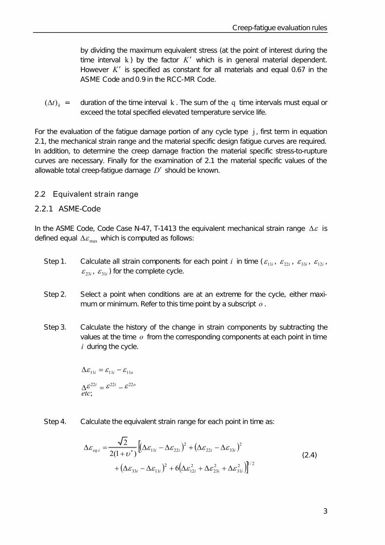
In the ASME Code, Code Case N-47, T-1413 the equivalent mechanical strain range ε Δ is
defined equal maxε Δ which is computed as follows:
Step 1. Calculate all strain components for each point i in time ( i11ε , i22ε , i33ε , i12ε ,
i23ε , i31ε ) for the complete cycle.
Step 2. Select a point when conditions are at an extreme for the cycle, either maxi-
mum or minimum. Refer to this time point by a subscript o .
Step 3. Calculate the history of the change in strain components by subtracting the
values at the time o from the corresponding components at each point in time
i during the cycle.
;
222222
111111
etc
oii
oii
ε ε ε
ε ε ε
−=Δ
−=Δ
Step 4. Calculate the equivalent strain range for each point in time as:
( ) ( )[
( ) ( )] 2/12
31
2
23
2
12
2
1133
2
3322
2
2211.
6
)1(2
2
iiiii
iiiiieq
ε ε ε ε ε
ε ε ε ε υ
ε
Δ+Δ+Δ+Δ−Δ+
Δ−Δ+Δ−Δ+
=Δ∗
(2.4)
7/30/2019 High Temp Creep-fatigue Crit for Fusion Eurofer 97
http://slidepdf.com/reader/full/high-temp-creep-fatigue-crit-for-fusion-eurofer-97 12/40
Creep-fatigue evaluation rules
4
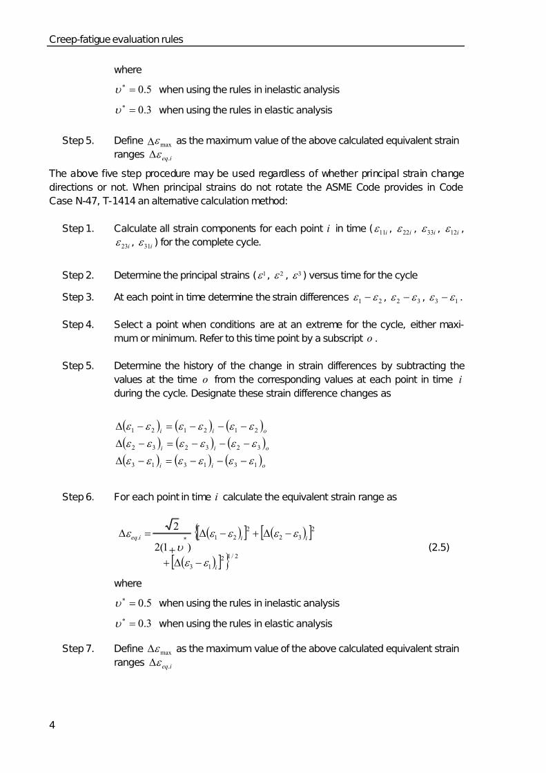
where
5.0=∗υ when using the rules in inelastic analysis
3.0=∗υ when using the rules in elastic analysis
Step 5. Define maxε Δ as the maximum value of the above calculated equivalent strain
ranges ieq.ε Δ
The above five step procedure may be used regardless of whether principal strain change
directions or not. When principal strains do not rotate the ASME Code provides in Code
Case N-47, T-1414 an alternative calculation method:
Step 1. Calculate all strain components for each point i in time ( i11ε , i22ε , i33ε , i12ε ,
i23ε , i31ε ) for the complete cycle.
Step 2. Determine the principal strains ( 1ε , 2ε , 3ε ) versus time for the cycle
Step 3. At each point in time determine the strain differences 21 ε ε − , 32 ε ε − , 13 ε ε − .
Step 4. Select a point when conditions are at an extreme for the cycle, either maxi-
mum or minimum. Refer to this time point by a subscript o .
Step 5. Determine the history of the change in strain differences by subtracting the
values at the time o from the corresponding values at each point in time i
during the cycle. Designate these strain difference changes as
( ) ( ) ( )
( ) ( ) ( )
( ) ( ) ( )oii
oii
oii
131313
323232
212121
ε ε ε ε ε ε
ε ε ε ε ε ε
ε ε ε ε ε ε
−−−=−Δ
−−−=−Δ
−−−=−Δ
Step 6. For each point in time i calculate the equivalent strain range as
( )[ ] ( )[ ]{
( )[ ] } 2/12
13
2
32
2
21.
)1(2
2
i
iiieq
ε ε
ε ε ε ε
υ
ε
−Δ+
−Δ+−Δ
+
=Δ∗
(2.5)
where
5.0=∗υ when using the rules in inelastic analysis
3.0=∗υ when using the rules in elastic analysis
Step 7. Define maxε Δ as the maximum value of the above calculated equivalent strain
ranges ieq.ε Δ
7/30/2019 High Temp Creep-fatigue Crit for Fusion Eurofer 97
http://slidepdf.com/reader/full/high-temp-creep-fatigue-crit-for-fusion-eurofer-97 13/40
Creep-fatigue evaluation rules
5
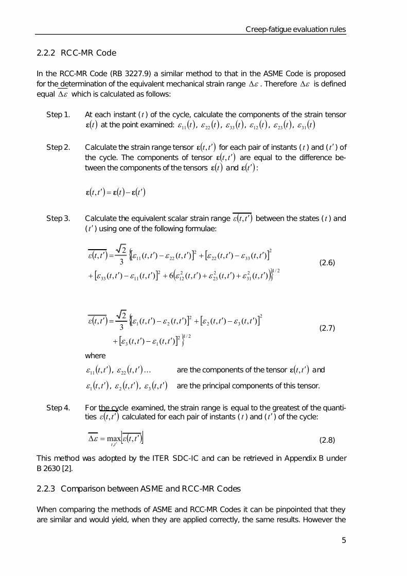
2.2.2 RCC-MR Code
In the RCC-MR Code (RB 3227.9) a similar method to that in the ASME Code is proposed
for the determination of the equivalent mechanical strain range ε Δ . Therefore ε Δ is defined
equal ε Δ which is calculated as follows:
Step 1. At each instant (t ) of the cycle, calculate the components of the strain tensor
( )t ε at the point examined: ( )t 11ε , ( )t 22ε , ( )t 33ε , ( )t 12ε , ( )t 23ε , ( )t 31ε
Step 2. Calculate the strain range tensor ( )t t ′,ε for each pair of instants ( t ) and (t ′) of
the cycle. The components of tensor ( )t t ′,ε are equal to the difference be-
tween the components of the tensors ( )t ε and ( )t ′ε :
( ) ( ) ( )t t t t ′−=′ εεε ,
Step 3. Calculate the equivalent scalar strain range ( )t t ε ′, between the states (t ) and
(t ′) using one of the following formulae:
( ) [ ] [ ]{
[ ] ( )} 2/12
31
2
23
2
12
2
1133
2
3322
2
2211
),(),(),(6),(),(
),(),(),(),(3
2,
t t t t t t t t t t
t t t t t t t t t t ε
′+′+′+′−′+
′−′+′−′=′
ε ε ε ε ε
ε ε ε ε (2.6)
( ) [ ] [ ]{
[ ] } 2/12
13
2
32
2
21
),(),(
),(),(),(),(3
2,
t t t t
t t t t t t t t t t ε
′−′+
′−′+′−′=′
ε ε
ε ε ε ε (2.7)
where
( )t t ′,11ε , ( )t t ′,22ε … are the components of the tensor ( )t t ′,ε and
( )t t ′,1ε , ( )t t ′,2ε , ( )t t ′,3ε are the principal components of this tensor.
Step 4. For the cycle examined, the strain range is equal to the greatest of the quanti-ties ( )t t ε ′, calculated for each pair of instants ( t ) and (t ′) of the cycle:
( )t t ε
t t ′=Δ
′,max
,ε (2.8)
This method was adopted by the ITER SDC-IC and can be retrieved in Appendix B under
B 2630 [2].
2.2.3 Comparison between ASME and RCC-MR Codes
When comparing the methods of ASME and RCC-MR Codes it can be pinpointed that they
are similar and would yield, when they are applied correctly, the same results. However the
7/30/2019 High Temp Creep-fatigue Crit for Fusion Eurofer 97
http://slidepdf.com/reader/full/high-temp-creep-fatigue-crit-for-fusion-eurofer-97 14/40
Creep-fatigue evaluation rules
6
selection of the point in time when conditions are at an extreme for the cycle, step 2 of T-
1413 and step 4 of T-1414, respectively, is not a straightforward task particularly in inelastic
analysis which might be a weak point for the ASME method. On the other hand the use of
the principal components of the strain tensor to calculate the equivalent strain range is in the
ASME method strictly limited to the case where the directions of the principal strains do not
rotate which is not the case in the RCC-MR method where the equations 2.6 and 2.7 are
supposed to deliver the same values what they do not necessarily do when the directions of
the principal strains rotate.
2.3 Design fatigue curves
Design fatigue curves for a material will be constructed according to the criteria of the ASME
(Section III, Division 1 – Appendices, III-2200) and the RCC-MR (A3.GEN.23) codes in a
similar ways. They are obtained from fatigue lifetime (number of cycles to rupture) data of
uniaxial strain-controlled fatigue (low cycle fatigue, LCF) tests performed with a strain rate in
the order of 13 sec10 −− . A best fit to experimental data is obtained by applying the method of
least squares to the logarithms of the strain range values. The design fatigue curves are then
deduced from the best fit curve by applying a factor of 2 on strain range or a factor of 20 on
cycles, whichever is the more conservative at each point. These factors are intended to
cover effects such as those of the environment, the scale (between the material and the test
specimen), surface finish and data scatter [4]. They in no case constitute a safety coefficient.
2.4 Stress-to-rupture curves
In the ASME as well as RCC-MR codes the stress-to-rupture curves to be used are derived
from lifetime data of creep tests. They deliver for a given temperature and time the minimum
stress value r S which yields to rupture at the given temperature after the given time.
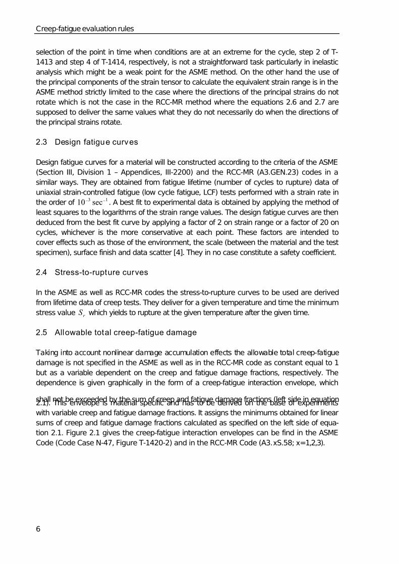
2.5 Allowable total creep-fatigue damage
Taking into account nonlinear damage accumulation effects the allowable total creep-fatigue
damage is not specified in the ASME as well as in the RCC-MR code as constant equal to 1
but as a variable dependent on the creep and fatigue damage fractions, respectively. The
dependence is given graphically in the form of a creep-fatigue interaction envelope, which
shall not be exceeded by the sum of creep and fatigue damage fractions (left side in equation2.1). This envelope is material specific and has to be derived on the base of experiments
with variable creep and fatigue damage fractions. It assigns the minimums obtained for linear
sums of creep and fatigue damage fractions calculated as specified on the left side of equa-
tion 2.1. Figure 2.1 gives the creep-fatigue interaction envelopes can be find in the ASME
Code (Code Case N-47, Figure T-1420-2) and in the RCC-MR Code (A3.xS.58; x=1,2,3).
7/30/2019 High Temp Creep-fatigue Crit for Fusion Eurofer 97
http://slidepdf.com/reader/full/high-temp-creep-fatigue-crit-for-fusion-eurofer-97 15/40
Application of the rules to EUROFER 97
7
0 0.2 0.4 0.6 0.8 1.0
Σ ⎯ n
N d
0
0.2
0.4
0.6
0.8
1.0
Σ ⎯ t T
d
304 and 316 stainless Steels(ASME and RCC-MR)
2-1/4 Cr - 1 Mo and Ni-Fe-Cr Alloy 800H(ASME)
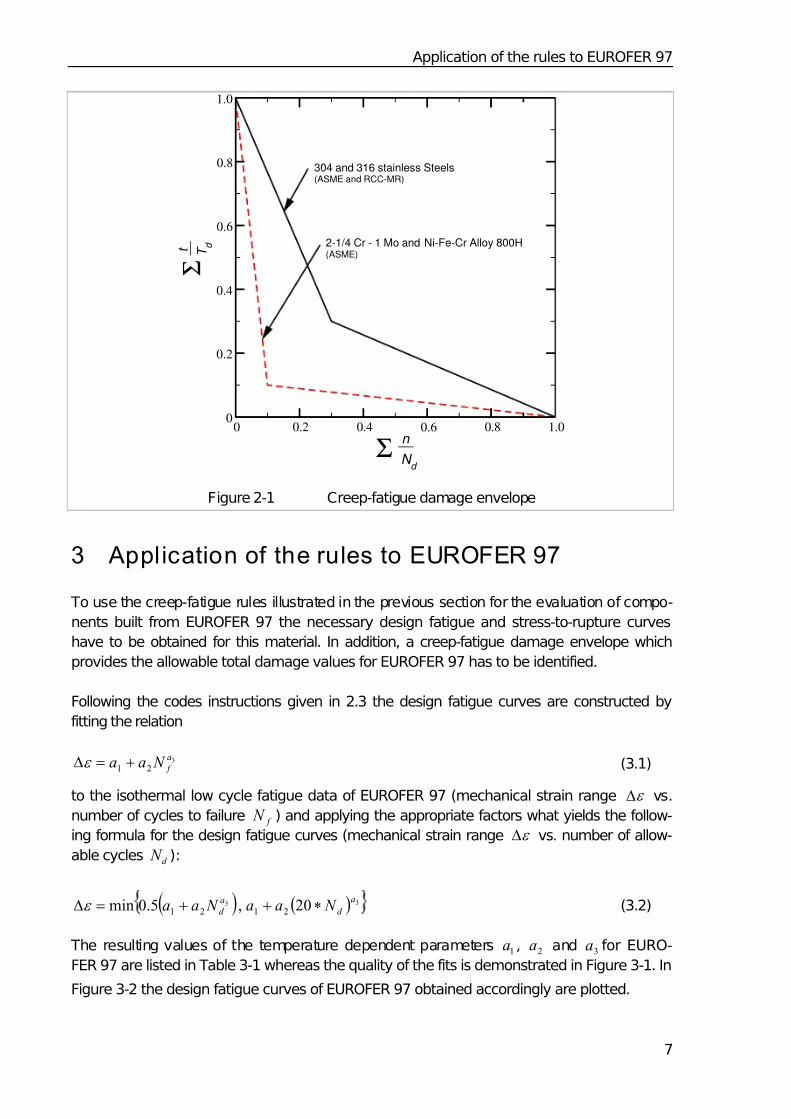
Figure 2-1 Creep-fatigue damage envelope
3 Application of the rules to EUROFER 97
To use the creep-fatigue rules illustrated in the previous section for the evaluation of compo-
nents built from EUROFER 97 the necessary design fatigue and stress-to-rupture curves
have to be obtained for this material. In addition, a creep-fatigue damage envelope which
provides the allowable total damage values for EUROFER 97 has to be identified.
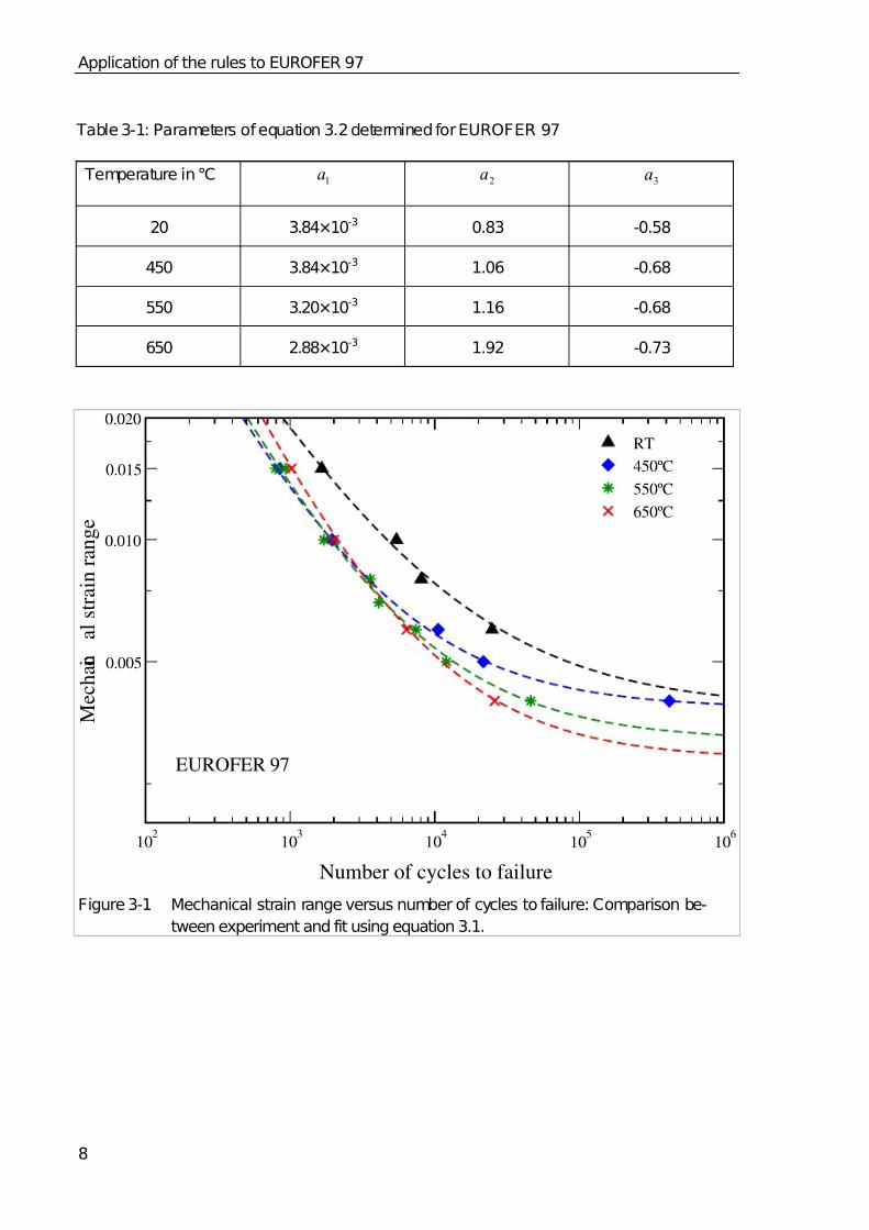
Following the codes instructions given in 2.3 the design fatigue curves are constructed by
fitting the relation
3
21
a
f N aa +=Δε (3.1)
to the isothermal low cycle fatigue data of EUROFER 97 (mechanical strain range ε Δ vs.
number of cycles to failure f N ) and applying the appropriate factors what yields the follow-
ing formula for the design fatigue curves (mechanical strain range ε Δ vs. number of allow-
able cycles d N ):
( ) ( ) 33 20,5.0min 2121
a
d
a
d N aa N aa ∗++=Δε (3.2)
The resulting values of the temperature dependent parameters 1a , 2a and 3a for EURO-
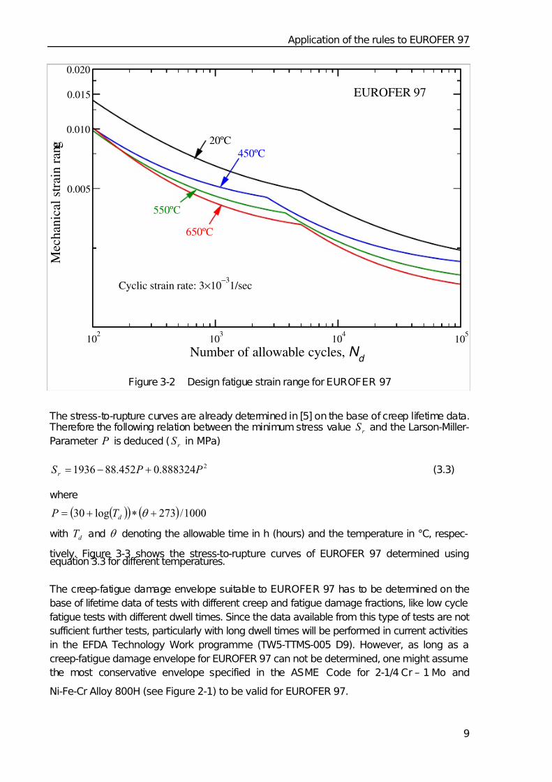
FER 97 are listed in Table 3-1 whereas the quality of the fits is demonstrated in Figure 3-1. In
Figure 3-2 the design fatigue curves of EUROFER 97 obtained accordingly are plotted.
7/30/2019 High Temp Creep-fatigue Crit for Fusion Eurofer 97
http://slidepdf.com/reader/full/high-temp-creep-fatigue-crit-for-fusion-eurofer-97 16/40
Application of the rules to EUROFER 97
8
102
103
104
105
106
Number of cycles to failure
0.005
0.010
0.015
0.020
M e c h a n i c
a l s t r a i n r a n g e
RT
450ºC
550ºC
650ºC
EUROFER 97
Figure 3-1 Mechanical strain range versus number of cycles to failure: Comparison be-
tween experiment and fit using equation 3.1.
Table 3-1: Parameters of equation 3.2 determined for EUROFER 97
Temperature in °C 1a 2a 3a
20 3.84×10⁻³ 0.83 -0.58
450 3.84×10⁻³ 1.06 -0.68
550 3.20×10⁻³ 1.16 -0.68
650 2.88×10⁻³ 1.92 -0.73
7/30/2019 High Temp Creep-fatigue Crit for Fusion Eurofer 97
http://slidepdf.com/reader/full/high-temp-creep-fatigue-crit-for-fusion-eurofer-97 17/40
Application of the rules to EUROFER 97
9
102
103
104
105
Number of allowable cycles, N d
0.005
0.010
0.015
0.020
M e c h a n i c a l s t r a i n r a n g e
EUROFER 97
Cyclic strain rate: 3×10⁻³
1/sec
20ºC
550ºC
450ºC
650ºC
Figure 3-2 Design fatigue strain range for EUROFER 97
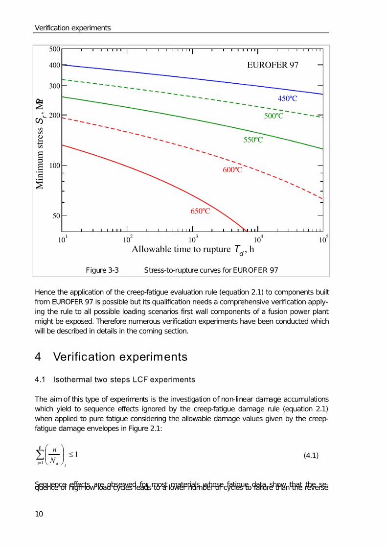
The stress-to-rupture curves are already determined in [5] on the base of creep lifetime data. Therefore the following relation between the minimum stress value r S and the Larson-Miller-
Parameter P is deduced ( r S in MPa)
2888324.0452.881936 P P S r +−= (3.3)
where
( )( ) ( ) 1000/273log30 +∗+= θ d T P
with d T and θ denoting the allowable time in h (hours) and the temperature in °C, respec-
tively. Figure 3-3 shows the stress-to-rupture curves of EUROFER 97 determined usingequation 3.3 for different temperatures.
The creep-fatigue damage envelope suitable to EUROFER 97 has to be determined on the
base of lifetime data of tests with different creep and fatigue damage fractions, like low cycle
fatigue tests with different dwell times. Since the data available from this type of tests are not
sufficient further tests, particularly with long dwell times will be performed in current activities
in the EFDA Technology Work programme (TW5-TTMS-005 D9). However, as long as a
creep-fatigue damage envelope for EUROFER 97 can not be determined, one might assume
the most conservative envelope specified in the ASME Code for 2-1/4 Cr – 1 Mo and
Ni-Fe-Cr Alloy 800H (see Figure 2-1) to be valid for EUROFER 97.
7/30/2019 High Temp Creep-fatigue Crit for Fusion Eurofer 97
http://slidepdf.com/reader/full/high-temp-creep-fatigue-crit-for-fusion-eurofer-97 18/40
Verification experiments
10
101
102
103
104
105
Allowable time to rupture T d
, h
50
100
200
300
400
500
M i n i m u m s t r e s s S
r ,
M P a
EUROFER 97
550ºC
450ºC
650ºC
500ºC
600ºC
Figure 3-3 Stress-to-rupture curves for EUROFER 97
Hence the application of the creep-fatigue evaluation rule (equation 2.1) to components built
from EUROFER 97 is possible but its qualification needs a comprehensive verification apply-
ing the rule to all possible loading scenarios first wall components of a fusion power plant
might be exposed. Therefore numerous verification experiments have been conducted which
will be described in details in the coming section.
4 Verification experiments
4.1 Isothermal two steps LCF experiments
The aim of this type of experiments is the investigation of non-linear damage accumulations
which yield to sequence effects ignored by the creep-fatigue damage rule (equation 2.1)
when applied to pure fatigue considering the allowable damage values given by the creep-
fatigue damage envelopes in Figure 2.1:
1
j
p
1 j
≤⎟⎟ ⎠
⎞⎜⎜⎝
⎛ ∑= d N
n (4.1)
Sequence effects are observed for most materials whose fatigue data show that the se-quence of high-low load cycles leads to a lower number of cycles to failure than the reverse

7/30/2019 High Temp Creep-fatigue Crit for Fusion Eurofer 97
http://slidepdf.com/reader/full/high-temp-creep-fatigue-crit-for-fusion-eurofer-97 19/40
Verification experiments
11
low-high cycles. To quantify these effects in the fatigue behaviour of EUROFER 97 isother-
mal two steps LCF experiments have been performed.
4.1.1 Experimental
The isothermal two steps experiments were carried out using radial polished round speci-
mens (diameter 0d = 8,8 mm, gauge length 0l = 20 mm) that were fabricated from one plate
in the as delivered state [6]. They were performed in a strain controlled manner (strain rate
ε & =3
103−× , ratio of minimum to maximum strain R = -1) at 450°C and 550°C, respectively,
using a hydraulic testing machine by MTS (type 810 with a TestStar IIs controller) that is
equipped with a quad elliptical heating chamber from R-I CONTROLS.
The load conditions were varied in the two steps experiments by changing the total strain
amplitude ε Δ from 1.0 % to 0.6 % (or vice versa). The respective switch point was given by
a variation of the number of cycles in the first step depending on a different ratio between the
number of cycles and the number of cycles to failure ( j j / f N n with j as step number – j f N
determined in single-step experiments for the respective jε Δ ). After changing the total strain
amplitude, the test was continued by the second step until fracture. Figure 4-1 shows an ex-
ample of the peak stress oσ as a function of the number of cycles n in a test at a total strain
amplitude of ε Δ = 1.0 % in the first step. From the curve, the material parameter jd n (num-
ber of cycles to macroscopic damage where the curve leaves its linear behaviour because of
a decreasing cross-section resulting from the fusion of micro-cracks to a macro-crack and
the following crack propagation) can be determined. For comparison, the number of cycles to
failure j f
n is determined at the peak stress value equal to the peak stress at jd
n decreased
by 30 %.
0 1000 2000 3000 4000 5000Number of cycles
0
100
200
300
400
500
P e a k s t r e s
s , M P a
n1
nd 1
n f 2
T = 450ºC
Δε 1
= 1.0% (n1 / N
f 1= 0.5)
Δε 2
= 0.6% (until fracture)
Figure 4-1 Peak stress vs. number of cycles, an example of a 2-step experiment, beginning
with 1ε Δ = 1.0 % in the first step

7/30/2019 High Temp Creep-fatigue Crit for Fusion Eurofer 97
http://slidepdf.com/reader/full/high-temp-creep-fatigue-crit-for-fusion-eurofer-97 20/40
Verification experiments
12
4.1.2 Results
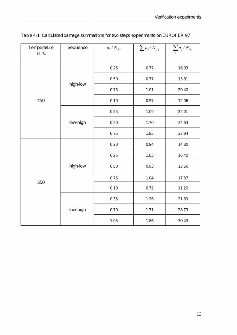
When plotting the results of the two steps experiments in a Palmgren-Miner diagram [7] (seeFigure 4-2), non-linear damage accumulation can be recognized. Beginning with the high
total strain amplitude ( 1ε Δ = 1.0 %) leads to lifetimes shorter than those expected assuming
linear damage accumulation, particularly with decreasing 11 / f N n ratio, i.e. 1/ j j <∑ f N n . In
contrast to this, starting with a low total strain amplitude ( 1ε Δ = 0.6 %) leads to clearly longer
lifetimes than those expected assuming linear damage accumulation, i.e. 1/ j j >∑ f N n .
Consequently, the allowable damage summation ∑ j j / f N n must be lower than the mini-
mum value obtained from these experiments which is equal to 0.57 so far (s. Table 4-1).However when calculating the damage summation using the number of allowable cycles
jd N instead of j f N according to equation 4.1 the allowable damage summation ∑ j j / d N n
are greater than 1 and less than 11.2 (s. Table 4-1). This reveals that the creep-fatigue dam-age rule applied to pure fatigue (equation 4.1) is on the safe side and might even be too con-
servative when applied to EUROFER 97.
0 0.25 0.50 0.75 1.00 1.25
⎯⎯
n1
N f 1
0
0.25
0.50
0.75
1.00
1.25
⎯ ⎯
n 2
N f 2
high-low, 450ºC
low-high, 450ºC
high,low, 550ºC
low-high, 550ºC
EUROFER 97
Figure 4-2 Results of the 2-step experiment, plotted in a Palmgren-Miner diagram
7/30/2019 High Temp Creep-fatigue Crit for Fusion Eurofer 97
http://slidepdf.com/reader/full/high-temp-creep-fatigue-crit-for-fusion-eurofer-97 21/40
Verification experiments
13
Table 4-1: Calculated damage summations for two steps experiments on EUROFER 97
Temperature
in °C
Sequence 11 / f N n ∑ j
j j / f N n ∑ j
j j / d N n
0.25 0.77 16.03
0.50 0.77 15.81
0.75 1.01 20.40
high-low
0.10 0.57 12.06
0.25 1.09 22.01
0.50 1.70 34.63
450
low-high
0.75 1.85 37.94
0.20 0.94 14.80
0.25 1.03 16.40
0.50 0.93 15.56
0.75 1.04 17.87
high-low
0.10 0.72 11.20
0.35 1.26 21.69
0.70 1.71 28.79
550
low-high
1.05 1.86 30.43
7/30/2019 High Temp Creep-fatigue Crit for Fusion Eurofer 97
http://slidepdf.com/reader/full/high-temp-creep-fatigue-crit-for-fusion-eurofer-97 22/40
Verification experiments
14
4.2 Thermomechanical fatigue experiments
4.2.1 Experimental
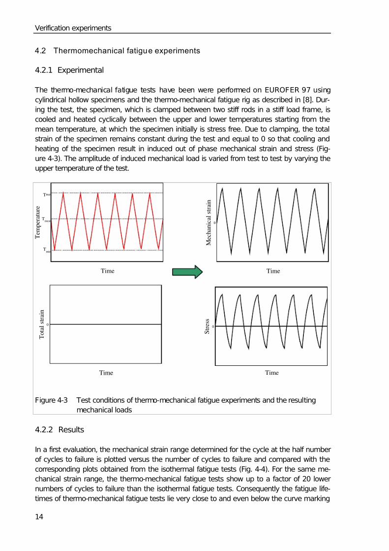
The thermo-mechanical fatigue tests have been were performed on EUROFER 97 using
cylindrical hollow specimens and the thermo-mechanical fatigue rig as described in [8]. Dur-
ing the test, the specimen, which is clamped between two stiff rods in a stiff load frame, is
cooled and heated cyclically between the upper and lower temperatures starting from the
mean temperature, at which the specimen initially is stress free. Due to clamping, the total
strain of the specimen remains constant during the test and equal to 0 so that cooling and
heating of the specimen result in induced out of phase mechanical strain and stress (Fig-
ure 4-3). The amplitude of induced mechanical load is varied from test to test by varying the
upper temperature of the test.
Time
T e m p e r a t u r e
Tmean
Tmin
Tmax
Time
M e c h a n i c a l s t r a i n
0
Time
T o t a l s t r a i n
0
Time
S t r e s s
0
Figure 4-3 Test conditions of thermo-mechanical fatigue experiments and the resulting
mechanical loads
4.2.2 Results
In a first evaluation, the mechanical strain range determined for the cycle at the half number
of cycles to failure is plotted versus the number of cycles to failure and compared with the
corresponding plots obtained from the isothermal fatigue tests (Fig. 4-4). For the same me-
chanical strain range, the thermo-mechanical fatigue tests show up to a factor of 20 lower
numbers of cycles to failure than the isothermal fatigue tests. Consequently the fatigue life-
times of thermo-mechanical fatigue tests lie very close to and even below the curve marking

7/30/2019 High Temp Creep-fatigue Crit for Fusion Eurofer 97
http://slidepdf.com/reader/full/high-temp-creep-fatigue-crit-for-fusion-eurofer-97 23/40
7/30/2019 High Temp Creep-fatigue Crit for Fusion Eurofer 97
http://slidepdf.com/reader/full/high-temp-creep-fatigue-crit-for-fusion-eurofer-97 24/40
Verification experiments
16
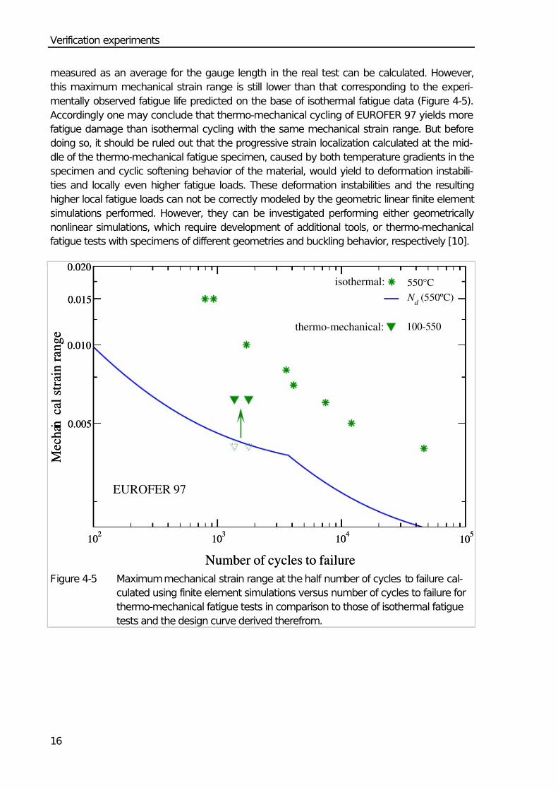
measured as an average for the gauge length in the real test can be calculated. However,
this maximum mechanical strain range is still lower than that corresponding to the experi-
mentally observed fatigue life predicted on the base of isothermal fatigue data (Figure 4-5).
Accordingly one may conclude that thermo-mechanical cycling of EUROFER 97 yields more
fatigue damage than isothermal cycling with the same mechanical strain range. But before
doing so, it should be ruled out that the progressive strain localization calculated at the mid-
dle of the thermo-mechanical fatigue specimen, caused by both temperature gradients in the
specimen and cyclic softening behavior of the material, would yield to deformation instabili-
ties and locally even higher fatigue loads. These deformation instabilities and the resulting
higher local fatigue loads can not be correctly modeled by the geometric linear finite element
simulations performed. However, they can be investigated performing either geometrically
nonlinear simulations, which require development of additional tools, or thermo-mechanical
fatigue tests with specimens of different geometries and buckling behavior, respectively [10].
102
103
104
105
Number of cycles to failure
0.005
0.010
0.015
0.020
M e c h a n i c a l s t r a i n r a n g e
550°C
N d
(550ºC)
102
103
104
105
Number of cycles to failure
0.005
0.010
0.015
0.020
M e c h a n i c a l s t r a i n r a n g e
100-550
EUROFER 97
isothermal:
thermo-mechanical:
Figure 4-5 Maximum mechanical strain range at the half number of cycles to failure cal-
culated using finite element simulations versus number of cycles to failure for
thermo-mechanical fatigue tests in comparison to those of isothermal fatigue
tests and the design curve derived therefrom.
7/30/2019 High Temp Creep-fatigue Crit for Fusion Eurofer 97
http://slidepdf.com/reader/full/high-temp-creep-fatigue-crit-for-fusion-eurofer-97 25/40
Verification experiments
17
4.3 Isothermal multi-axial fatigue experiments
Two types of strain controlled multiaxial fatigue tests have been performed on EUROFER 97
tube specimens:
1. Cyclic pull-push in axial and circumferential directions of the specimen and thus with
fixed directions of principal stresses and strains (FPSS) at room temperature. The
tests performed in that way will be called in the following FPSS tests.
2. Cyclic pull-push and alternating torsion in the axial direction of the specimens which
yield the directions of the principal stresses and strains are not fixed for non-
proportional loading conditions (phase shift °°≠ 1800 or ) and rotate during a cycle
(rotating principal stresses and strains RPSS). These tests, called in the following
RPSS tests, were performed at room temperature and 500°C.
4.3.1 Experimental details
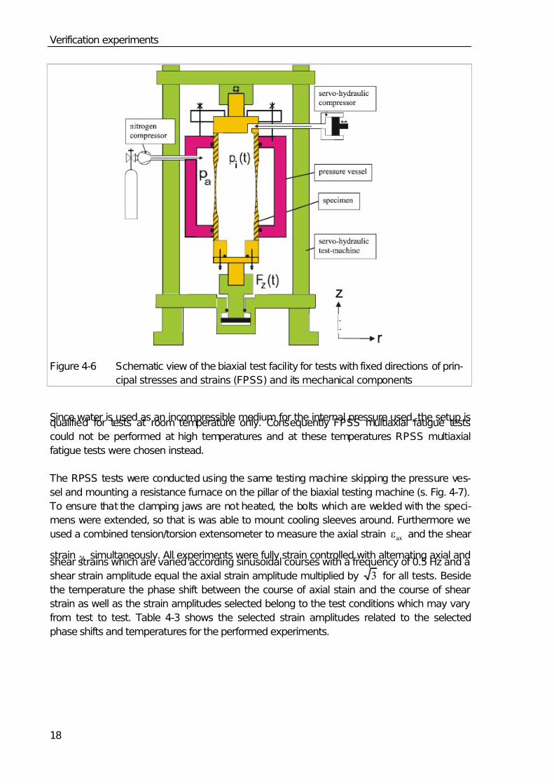
The experimental setup used to perform the FPSS multiaxial fatigue tests consists of a
commercial tension-torsion machine extended with a pressure vessel allowing the application
of alternating circumferential load on tube specimen by maintaining the external pressure
constant and varying the internal pressure [11][12]. A schematic view of the setup is illus-
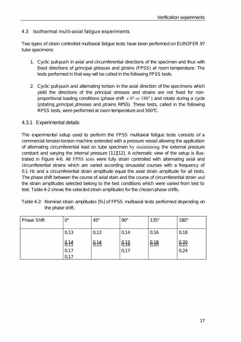
trated in Figure 4-6. All FPSS tests were fully strain controlled with alternating axial and
circumferential strains which are varied according sinusoidal courses with a frequency of
0.1 Hz and a circumferential strain amplitude equal the axial strain amplitude for all tests.
The phase shift between the course of axial stain and the course of circumferential strain and
the strain amplitudes selected belong to the test conditions which were varied from test to
test. Table 4-2 shows the selected strain amplitudes for the chosen phase shifts.
Table 4-2: Nominal strain amplitudes [%] of FPSS multiaxial tests performed depending on
the phase shift.
Phase Shift 0° 45° 90° 135° 180°
0,13
0,140,15
0,17
0,17
0,12
0,140,15
0,14
0,150,16
0,17
0,16
0,180,20
0,18
0,200,22
0,24
7/30/2019 High Temp Creep-fatigue Crit for Fusion Eurofer 97
http://slidepdf.com/reader/full/high-temp-creep-fatigue-crit-for-fusion-eurofer-97 26/40
Verification experiments
18
Figure 4-6 Schematic view of the biaxial test facility for tests with fixed directions of prin-
cipal stresses and strains (FPSS) and its mechanical components
Since water is used as an incompressible medium for the internal pressure used, the setup isqualified for tests at room temperature only. Consequently FPSS multiaxial fatigue tests
could not be performed at high temperatures and at these temperatures RPSS multiaxial
fatigue tests were chosen instead.
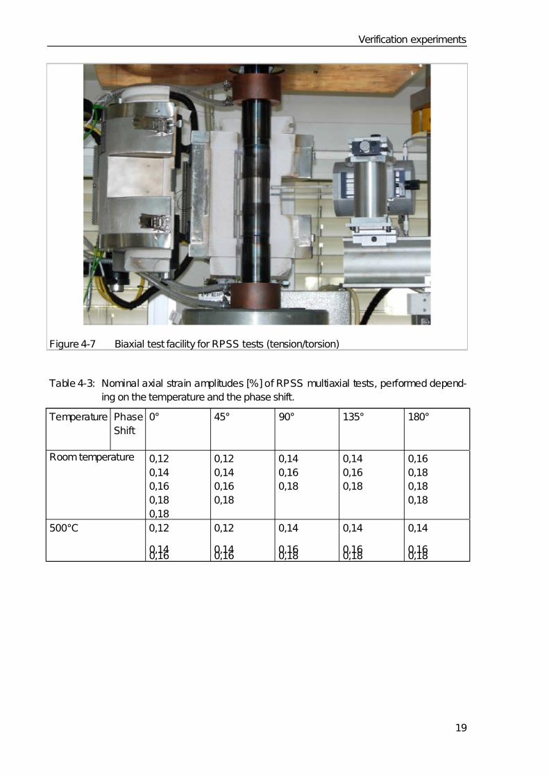
The RPSS tests were conducted using the same testing machine skipping the pressure ves-
sel and mounting a resistance furnace on the pillar of the biaxial testing machine (s. Fig. 4-7).
To ensure that the clamping jaws are not heated, the bolts which are welded with the speci-
mens were extended, so that is was able to mount cooling sleeves around. Furthermore we
used a combined tension/torsion extensometer to measure the axial strain εax and the shear
strain γ simultaneously. All experiments were fully strain controlled with alternating axial andshear strains which are varied according sinusoidal courses with a frequency of 0.5 Hz and a
shear strain amplitude equal the axial strain amplitude multiplied by 3 for all tests. Beside
the temperature the phase shift between the course of axial stain and the course of shear
strain as well as the strain amplitudes selected belong to the test conditions which may vary
from test to test. Table 4-3 shows the selected strain amplitudes related to the selected
phase shifts and temperatures for the performed experiments.
7/30/2019 High Temp Creep-fatigue Crit for Fusion Eurofer 97
http://slidepdf.com/reader/full/high-temp-creep-fatigue-crit-for-fusion-eurofer-97 27/40
Verification experiments
19
Figure 4-7 Biaxial test facility for RPSS tests (tension/torsion)
Table 4-3: Nominal axial strain amplitudes [%] of RPSS multiaxial tests, performed depend-
ing on the temperature and the phase shift.
Temperature Phase
Shift
0° 45° 90° 135° 180°
Room temperature 0,12
0,14
0,16
0,18
0,18
0,12
0,14
0,16
0,18
0,14
0,16
0,18
0,14
0,16
0,18
0,16
0,18
0,18
0,18
500°C 0,12
0,140,16
0,12
0,140,16
0,14
0,160,18
0,14
0,160,18
0,14
0,160,18

7/30/2019 High Temp Creep-fatigue Crit for Fusion Eurofer 97
http://slidepdf.com/reader/full/high-temp-creep-fatigue-crit-for-fusion-eurofer-97 28/40
Verification experiments
20
4.3.2 Experimental results
In the regime of low cycle fatigue the relevant parameter for failure is usually the inelastic
strain amplitude. Therefore in a first evaluation we plotted in a Manson-Coffin diagram the
equivalent inelastic strain range at half number of cycles to failure versus number of cycles to
failure. The equivalent inelastic strain range is calculated using a similar procedure to that
described in 2.2.2 (eq. 2.6) with the components of inelastic strain instead those of the total
mechanical strain are considered.
The resulting plot for the FPSS experiments at room temperature can be seen in Figure 4-8
where the lifetime data depending on the phase shift are compared to those of uniaxial tests.
It can recognized that the multiaxial loading with fixed directions of principal stresses and
strains (FPSS) yields lower lifetimes in the low cycle fatigue regime with non-monotonous
dependence on the phase shift. While the non-proportional multiaxial loading (phase shifts
45, 90 and 135°) seems to be the most damaging mode, the proportional multiaxial loading
with 180° phase shift yields higher lifetimes, very close to those of the corresponding uniaxial
loading, than the proportional multiaxial loading with 0° phase shift. In comparison to the
uniaxial loading the multiaxial FPSS with the same equivalent inelastic strain range have led
to up to 30 times lower lifetimes.
103
104
105
106
Number of cycles to failure
10-4
10-3
10-2
E q u
i v a l e n t i n e l a s t i c s t r a i n r a n
g e
0º
45º
90º
135º
180º
Uniaxial at RT
EUROFER 97
Figure 4-8 Equivalent inelastic strain range at half number of cycles to failure versus
number of cycles to failure for the multiaxial FPSS tests performed at roomtemperature.
7/30/2019 High Temp Creep-fatigue Crit for Fusion Eurofer 97
http://slidepdf.com/reader/full/high-temp-creep-fatigue-crit-for-fusion-eurofer-97 29/40
Verification experiments
21
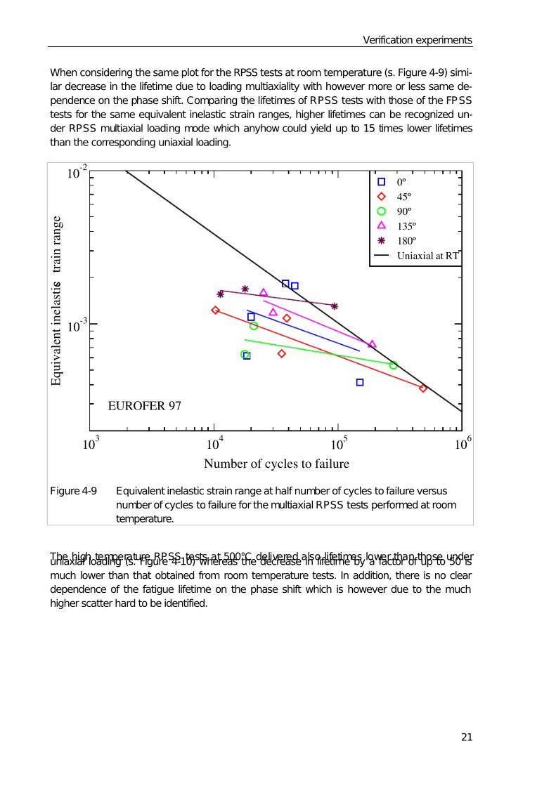
When considering the same plot for the RPSS tests at room temperature (s. Figure 4-9) simi-
lar decrease in the lifetime due to loading multiaxiality with however more or less same de-
pendence on the phase shift. Comparing the lifetimes of RPSS tests with those of the FPSS
tests for the same equivalent inelastic strain ranges, higher lifetimes can be recognized un-
der RPSS multiaxial loading mode which anyhow could yield up to 15 times lower lifetimes
than the corresponding uniaxial loading.
103
104
105
106
Number of cycles to failure
10-3
10-2
E q u i v a l e n t i n e l a s t i c s t r a i n r a n g e
0º
45º
90º
135º
180º
Uniaxial at RT
EUROFER 97
Figure 4-9 Equivalent inelastic strain range at half number of cycles to failure versus
number of cycles to failure for the multiaxial RPSS tests performed at room
temperature.
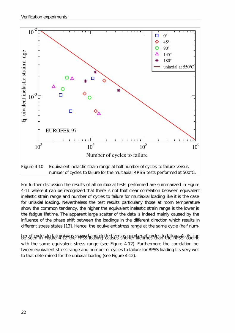
The high temperature RPSS tests at 500°C delivered also lifetimes lower than those underuniaxial loading (s. Figure 4-10) whereas the decrease in lifetime by a factor of up to 50 is
much lower than that obtained from room temperature tests. In addition, there is no clear
dependence of the fatigue lifetime on the phase shift which is however due to the much
higher scatter hard to be identified.
7/30/2019 High Temp Creep-fatigue Crit for Fusion Eurofer 97
http://slidepdf.com/reader/full/high-temp-creep-fatigue-crit-for-fusion-eurofer-97 30/40
Verification experiments
22
103
104
105
106
Number of cycles to failure
10-3
10-2
E q u i v a l e n t i n e l a s t i c s t r a i n r a n g e
0º
45º
90º
135º
180º
uniaxial at 550ºC
EUROFER 97
Figure 4-10 Equivalent inelastic strain range at half number of cycles to failure versus
number of cycles to failure for the multiaxial RPSS tests performed at 500°C.
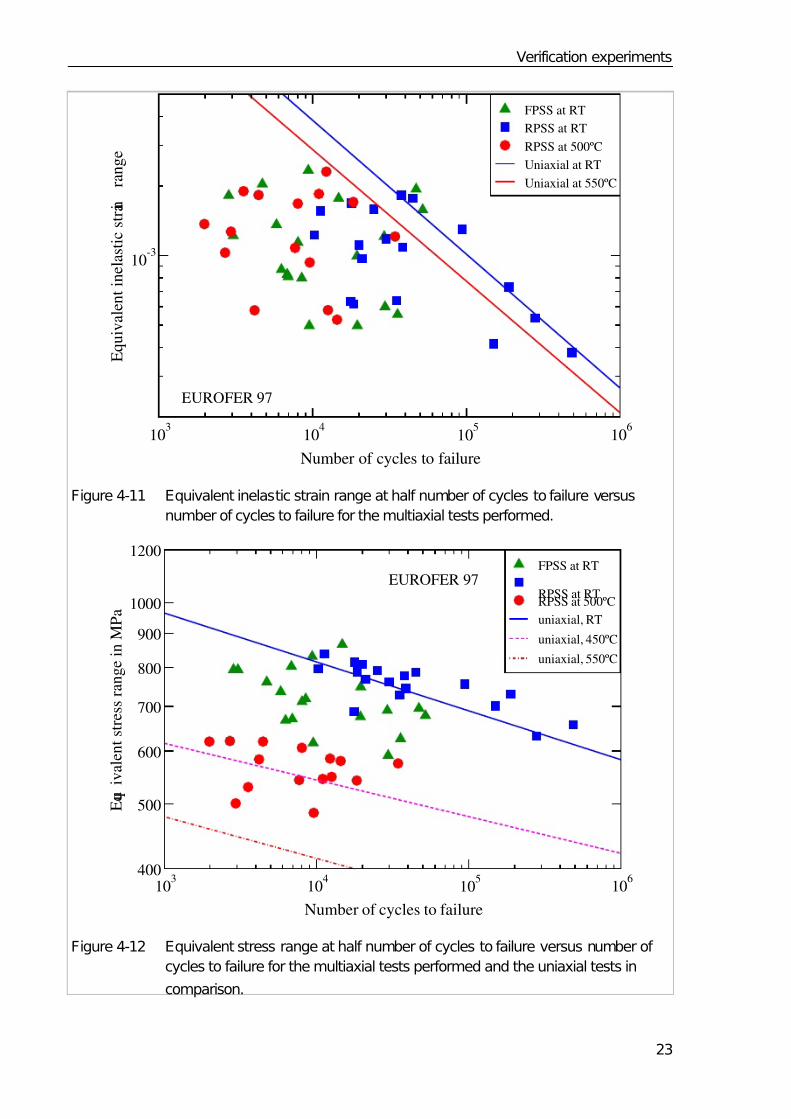
For further discussion the results of all multiaxial tests performed are summarized in Figure
4-11 where it can be recognized that there is not that clear correlation between equivalent
inelastic strain range and number of cycles to failure for multiaxial loading like it is the case
for uniaxial loading. Nevertheless the test results particularly those at room temperature
show the common tendency, the higher the equivalent inelastic strain range is the lower is
the fatigue lifetime. The apparent large scatter of the data is indeed mainly caused by the
influence of the phase shift between the loadings in the different direction which results in
different stress states [13]. Hence, the equivalent stress range at the same cycle (half num-
ber of cycles to failure) was viewed and plotted versus number of cycles to failure. As its canbe seen in Figure 4-12 the FPSS loading causes shorter lifetimes than the RPSS loading
with the same equivalent stress range (see Figure 4-12). Furthermore the correlation be-
tween equivalent stress range and number of cycles to failure for RPSS loading fits very well
to that determined for the uniaxial loading (see Figure 4-12).
7/30/2019 High Temp Creep-fatigue Crit for Fusion Eurofer 97
http://slidepdf.com/reader/full/high-temp-creep-fatigue-crit-for-fusion-eurofer-97 31/40
Verification experiments
23
103
104
105
106
Number of cycles to failure
10-3
E q u i v a l e n t i n e l a s t i c s t r a i n
r a n g e
FPSS at RT
RPSS at RT
RPSS at 500ºC
Uniaxial at RT
Uniaxial at 550ºC
EUROFER 97
Figure 4-11 Equivalent inelastic strain range at half number of cycles to failure versus
number of cycles to failure for the multiaxial tests performed.
103
104
105
106
Number of cycles to failure
400
500
600
700
800
900
1000
1200
E q u i v a l e n t s t r e s s r a n g e i n M P a
FPSS at RT
RPSS at RTRPSS at 500ºC
uniaxial, RT
uniaxial, 450ºC
uniaxial, 550ºC
EUROFER 97
Figure 4-12 Equivalent stress range at half number of cycles to failure versus number of
cycles to failure for the multiaxial tests performed and the uniaxial tests in
comparison.
7/30/2019 High Temp Creep-fatigue Crit for Fusion Eurofer 97
http://slidepdf.com/reader/full/high-temp-creep-fatigue-crit-for-fusion-eurofer-97 32/40
Verification experiments
24
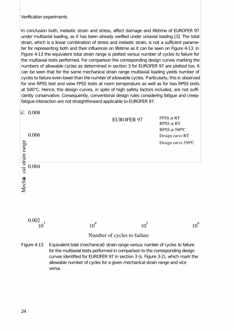
In conclusion both, inelastic strain and stress, affect damage and lifetime of EUROFER 97
under multiaxial loading, as it has been already verified under uniaxial loading [3]. The total
strain, which is a linear combination of stress and inelastic strain, is not a sufficient parame-
ter for representing both and their influences on lifetime as it can be seen on Figure 4-13. In
Figure 4-13 the equivalent total strain range is plotted versus number of cycles to failure for
the multiaxial tests performed. For comparison the corresponding design curves marking the
numbers of allowable cycles as determined in section 3 for EUROFER 97 are plotted too. It
can be seen that for the same mechanical strain range multiaxial loading yields number of
cycles to failure even lower than the number of allowable cycles. Particularly, this is observed
for one RPSS test and view FPSS tests at room temperature as well as for two RPSS tests
at 500°C. Hence, the design curves, in spite of high safety factors included, are not suffi-
ciently conservative. Consequently, conventional design rules considering fatigue and creep-
fatigue interaction are not straightforward applicable to EUROFER 97.
103
104
105
106
Number of cycles to failure
0.002
0.004
0.006
0.008
M e c h a n i
c a l s t r a i n r a n g e
FPSS at RT
RPSS at RT
RPSS at 500ºC
Design curve RT
Design curve 550ºC
EUROFER 97
Figure 4-13 Equivalent total (mechanical) strain range versus number of cycles to failure
for the multiaxial tests performed in comparison to the corresponding design
curves identified for EUROFER 97 in section 3 (s. Figure 3-2), which mark the
allowable number of cycles for a given mechanical strain range and vice
versa.

7/30/2019 High Temp Creep-fatigue Crit for Fusion Eurofer 97
http://slidepdf.com/reader/full/high-temp-creep-fatigue-crit-for-fusion-eurofer-97 33/40
Improved rules for EUROFER 97
25
5 Improved rules for EUROFER 97
Based on the results of the verification experiments evaluated and discussed above an im-
proved rule for determining the allowable number of cycles and thus the fatigue damage part
in eq. 2.1 has been developed within the EFDA task TW5-TTMS-005, D7.
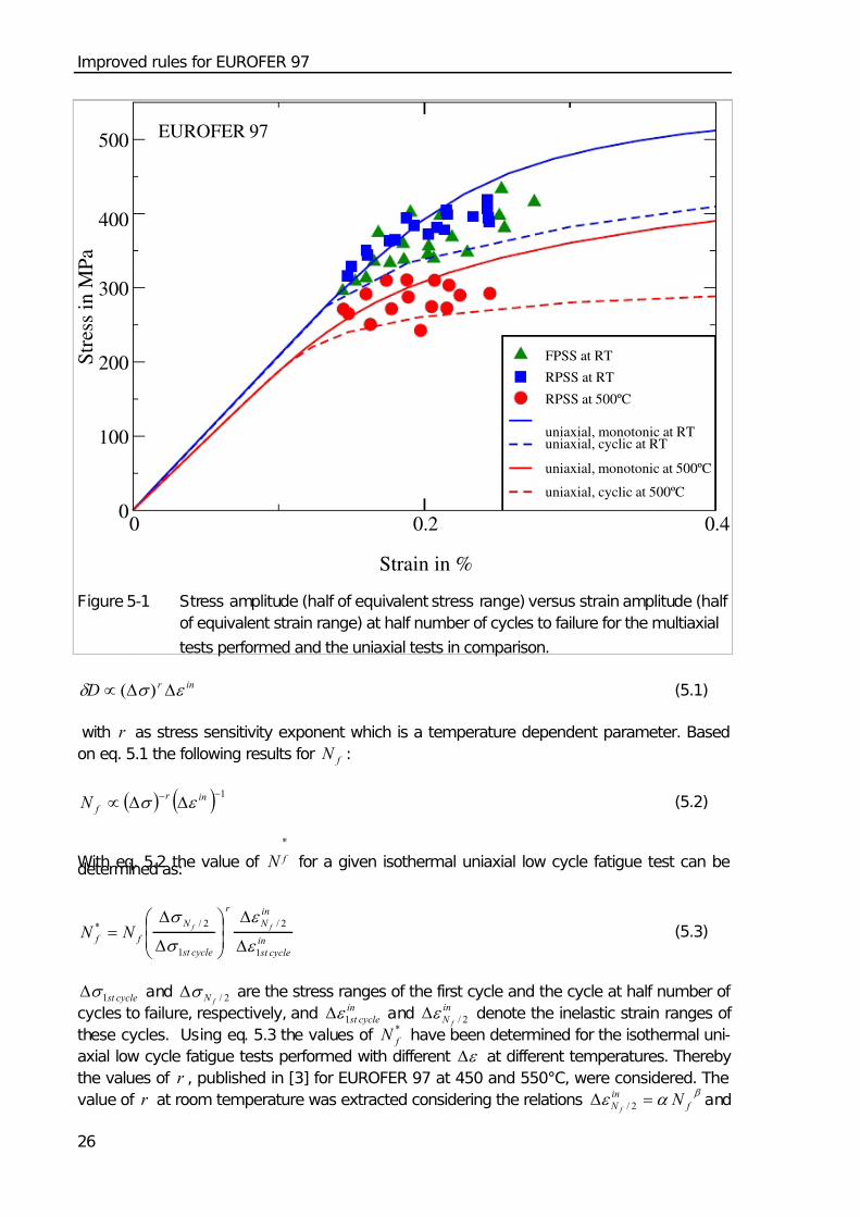
Starting to gather physical interpretation why the multiaxial fatigue tests have delivered life-
times lower than those expected on the base of uniaxial data we plotted the cyclic hardening
curves (half of equivalent stress range versus half of equivalent strain range, both of the cy-
cle at half number of cycles to failure) obtained from the multiaxial fatigue tests and com-
pared them with those determined from uniaxial fatigue tests and with the monotonic harden-
ing curves from uniaxial tensile tests as well (s. Figure 5-1). From Frigure 5-1 the following
can be recognized:
1. In the multiaxial fatigue tests with rotating principal stresses and strains (RPSS tests)
at room temperature and 500°C much lower softening is observed than that observed
in uniaxial fatigue tests.
2. In the multiaxial fatigue tests with fixed directions of principal stresses and strains
(FPSS tests) at room temperature a more pronounced softening is observed than that
observed in RPSS tests, which however achieves for few tests the softening level ob-
served in uniaxial fatigue tests.
Physically this can be explained by the following. Under RPSS multiaxial loading more glide
systems are indeed activated but with result that the inelastic deformation localized in the
different systems is smaller than that under uniaxial and FPSS loadings. Since localized de-
formation on the sub grain scale is necessary to break the carbides walls between the ferritic
phases and former martensitic laths yielding softening reduced softening is observed under
RPSS multiaxial loading. Obviously, such inelastic deformation localisations are more in fa-
vour under FPSS multiaxial loading and most in favour under uniaxial loading.
The low fatigue lifetimes observed in the multiaxial fatigue tests might be now, at least partly,
attributed in the case of RPSS and FPSS multiaxial tests to the reduced softening and thus
the higher stresses.
Based on these findings, the design fatigue curves for EUROFER 97 (Figure 3-2) are modi-
fied taking into account the cyclic softening and its dependence on the loading mode. There-
fore we considered again the basis of these curves, namely the isothermal low cycle fatigue
data of EUROFER 97 (mechanical strain range ε Δ vs. number of cycles to failure f N ) and
derived there from the relation between the mechanical strain range ε Δ and the hypothetical
number of cycles to failure *
f N which would be observed in the absence of softening. To
determine*
f N the damage model already developed for EUROFER 97 under low cycle fa-
tigue loading conditions is considered [3]. According to this model the damage accumulated
per cycle during a cyclic loading has the following dependence on stress and inelastic strainranges
7/30/2019 High Temp Creep-fatigue Crit for Fusion Eurofer 97
http://slidepdf.com/reader/full/high-temp-creep-fatigue-crit-for-fusion-eurofer-97 34/40
Improved rules for EUROFER 97
26
0 0.2 0.4
Strain in %
0
100
200
300
400
500
S t r e s s i n M P a
FPSS at RT
RPSS at RT
RPSS at 500ºC
uniaxial, monotonic at RTuniaxial, cyclic at RT
uniaxial, monotonic at 500ºC
uniaxial, cyclic at 500ºC
EUROFER 97
Figure 5-1 Stress amplitude (half of equivalent stress range) versus strain amplitude (half
of equivalent strain range) at half number of cycles to failure for the multiaxial
tests performed and the uniaxial tests in comparison.
inr D ε σ δ ΔΔ∝ )( (5.1)
with r as stress sensitivity exponent which is a temperature dependent parameter. Based
on eq. 5.1 the following results for f N :
( ) ( ) 1−− ΔΔ∝ inr
f N ε σ (5.2)
With eq. 5.2 the value of
*
f N for a given isothermal uniaxial low cycle fatigue test can bedetermined as:
in
cycle st
in
N
r
cycle st
N
f f
f f
N N 1
2/
1
2/*
ε
ε
σ
σ
Δ
Δ⎟⎟ ⎠
⎞⎜⎜⎝
⎛
Δ
Δ= (5.3)
cycle st 1σ Δ and 2/ f N σ Δ are the stress ranges of the first cycle and the cycle at half number of
cycles to failure, respectively, andin
cycle st 1ε Δ andin
N f 2/ε Δ denote the inelastic strain ranges of
these cycles. Using eq. 5.3 the values of *
f N have been determined for the isothermal uni-
axial low cycle fatigue tests performed with different ε Δ at different temperatures. Thereby
the values of r , published in [3] for EUROFER 97 at 450 and 550°C, were considered. The
value of r at room temperature was extracted considering the relations β
α ε f
in
N N f
=Δ 2/ and
7/30/2019 High Temp Creep-fatigue Crit for Fusion Eurofer 97
http://slidepdf.com/reader/full/high-temp-creep-fatigue-crit-for-fusion-eurofer-97 35/40
Improved rules for EUROFER 97
27
qin
N N f f p 2/2/ ε σ Δ=Δ fitted to the isothermal fatigue data at room temperature. After determin-
ing the values of *
f N , the relation between ε Δ and*
f N has been described by fitting the
following relation to the data obtained:
3*
21
b
f N bb +=Δε (5.4)
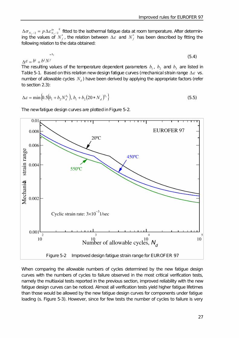
The resulting values of the temperature dependent parameters 1b , 2b and 3b are listed in
Table 5-1. Based on this relation new design fatigue curves (mechanical strain range ε Δ vs.
number of allowable cycles d N ) have been derived by applying the appropriate factors (refer
to section 2.3):
( ) ( ){ }33 20,5.0min 2121
b
d
b
d N bb N bb ∗++=Δε (5.5)
The new fatigue design curves are plotted in Figure 5-2.
102
103
104
105
Number of allowable cycles, N d
0.001
0.002
0.004
0.006
0.008
0.01
M e c h a n i c a l
s t r a i n r a n g e
EUROFER 97
Cyclic strain rate: 3×10⁻³
1/sec
20ºC
550ºC
450ºC
Figure 5-2 Improved design fatigue strain range for EUROFER 97
When comparing the allowable numbers of cycles determined by the new fatigue design
curves with the numbers of cycles to failure observed in the most critical verification tests,
namely the multiaxial tests reported in the previous section, improved reliability with the new
fatigue design curves can be noticed. Almost all verification tests yield higher fatigue lifetimes
than those would be allowed by the new fatigue design curves for components under fatigue
loading (s. Figure 5-3). However, since for few tests the number of cycles to failure is very

7/30/2019 High Temp Creep-fatigue Crit for Fusion Eurofer 97
http://slidepdf.com/reader/full/high-temp-creep-fatigue-crit-for-fusion-eurofer-97 36/40
Improved rules for EUROFER 97
28
close to the allowable number of cycles further verification of the new fatigue design curves
might be necessary.
Table 5-1: Parameters of equation 3.2 determined for EUROFER 97
Temperature in °C 1b 2b 3b
20 3.84×10⁻³ 0.56 -0.60
450 3.84×10⁻³ 0.36 -0.60
550 3.2×10⁻³ 0.31 -0.56
103
104
105
106
Number of cycles to failure
0.002
0.004
0.006
0.008
M e c h a n i c a l s t r a i n r a n g e
FPSS at RT
RPSS at RT
RPSS at 500ºC
Design curve RT
Design curve 550ºC
EUROFER 97
Figure 5-3 Equivalent total (mechanical) strain range versus number of cycles to failure for
the multiaxial tests performed in comparison to the corresponding improved de-
sign curves for EUROFER 97, which mark the allowable number of cycles for a
given mechanical strain range and vice versa.
7/30/2019 High Temp Creep-fatigue Crit for Fusion Eurofer 97
http://slidepdf.com/reader/full/high-temp-creep-fatigue-crit-for-fusion-eurofer-97 37/40
Summary and outlook
29
6 Summary and outlook
In this report the creep-fatigue design rules already established in the ASME and RCC-MR
codes have been reviewed, evaluated and reformulated for the assessment of components
built from EUROFER 97. Therefore creep and fatigue data of EUROFER 97 were processed
deriving the required design curves which were described in addition by analytical formula.
For the allowable sum of creep fatigue damage the most conservative values proposed in the
ASME code were adopted in a first approach.
To verify the rules, particularly those for fatigue, an extensive experimental program has
been conducted in which isothermal two steps LCF, thermo-mechanical fatigue and isother-
mal multiaxial fatigue experiments were performed. The results of these experiments showed
that the thermo-mechanical and multiaxial loading modes are much more damaging than the
uniaxial loading. The observed fatigue lifetimes for the same equivalent loads are much
lower than the uniaxial references and in many cases lower than those allowed by the formu-
lated design rules. This characteristic behaviour for EUROFER 97, and probably for all simi-
lar ferritic martensitic steels, has been attributed in a deeper evaluation of the verification
experiments to the cyclic softening behaviour of this material. The cyclic softening has been
found less pronounced under thermo-mechanical and multiaxial fatigue loading and most
pronounced under isothermal uniaxial fatigue loading yielding lower stresses in strain con-
trolled loadings and thus higher lifetimes. As a consequence, the fatigue design curves de-
rived from uniaxial fatigue data are not sufficiently conservative. In addition, the simulations
performed for the thermo-mechanical fatigue tests showed that cyclic softening leads to de-
formation localisation which might also contribute to the lifetime reduction. The non-
proportionality (phase shift) under multiaxial fatigue loading has also been found to have
negative influence on the lifetime.
To improve the reliability of the rules, new fatigue design curves were derived taking into
account the influence of reduced cyclic softening on lifetime. Therefore, a damage model
recently developed to describe the deterioration of EUROFER 97 under creep fatigue loading
has been used. However, even the new design curves cover reliably the lifetimes observed
in the verification experiments performed so far further verifications are recommended, par-
ticularly considering the lifetimes of the following types of experiments:
1. Isothermal multiaxial fatigue tests with higher loading amplitudes – using specimen
with improved buckling behaviour – at room as well as at high temperatures
2. Isothermal LCF tests with long dwell periods (up to hours) for the verification of as-
sumed allowable creep fatigue summations
3. Thermo-mechanical fatigue tests on different specimen geometries for the investi-
gation of the deformation localisation effects due to cyclic softening on the lifetime
4. A benchmark experiment in which a mockup built from EUROFER 97 will be testedunder thermo-mechanical multiaxial creep fatigue conditions.
7/30/2019 High Temp Creep-fatigue Crit for Fusion Eurofer 97
http://slidepdf.com/reader/full/high-temp-creep-fatigue-crit-for-fusion-eurofer-97 38/40
Acknowledgment
30
7 Acknowledgment
We would like to thank Dipl.-Ing. S. Knaak, M. Klotz and Dipl.-Ing. M. Lerch, members of our
scientific technical stuff, for their support in performing the verification experiments.
This work, supported by the European Communities under the contract of Association be-
tween EURATOM and Forschungszentrum Karlsruhe, was carried out within the framework
of the European Fusion Development Agreement. The views and opinions expressed herein
do not necessarily reflect those of the European Commission.
8 References
[1] B. van der Schaaf, F. Tavassoli, C. Fazio, E. Rigal, E. Diegele, R. Lindau and G. Le-
Marois, The development of EUROFER reduced activation steel, Fusion Engineering
and Design 69 (2003) 197-203.
[2] ITER Structural Design Criteria for In-Vessel Components (SDC-IC), G 74 MA 8 01-
05-28 W 0.2.
[3] J . Aktaa and R. Schmitt, High temperature deformation and damage behavior of
RAFM steels under low cycle fatigue loading: Experiments and modeling, Fusion En-
gineering and Design 81 (2006) 2221-2231.
[4] B.F. Langer, Design of pressure vessels for low cycle fatigue, J . Basic Engg. 84
(1962) 379-.
[5] F. Tavassoli, Fusion Demo Interim Design Criteria (DISDC) / Appendix A: Material
Design Limit Data / A3.S18E Eurofer Steel, DMN Technical Report,
DMN/DIR/NT/2004-000/A, 2004.
[6] M. Schirra, A. Falkenstein, P. Graf, S. Heger, H. Kempe, R. Lindau, H. Zimmermann,
Ergebnisse von Charakterisierungsuntersuchungen zu physikalischen und mechani-
schen Eigenschaften des martensitischen 9 % Cr-Stahls EUROFER 97, FZKA-Bericht6707, 2002.
[7] M. A. Miner, Cumulative Damage in Fatigue, J ournal of Applied Mechanics, ASME,
Vol. 12, No. 3, A159-A164, Sept. 1945.
[8] C. Petersen, Thermal fatigue behavior of low activation ferrite-martensite steels, J our-
nal of Nuclear Materials 258-263 (1998) 1285-1290.
[9] D. A. Miller and R. H. Priest, in High Temperature Fatigue: Properties and Prediction,
ed. R. P. Skelton, Elsevier Applied Science, pp. 113-175, 1987.
7/30/2019 High Temp Creep-fatigue Crit for Fusion Eurofer 97
http://slidepdf.com/reader/full/high-temp-creep-fatigue-crit-for-fusion-eurofer-97 39/40
References
31
[10] J . Aktaa, M. Klotz and C. Petersen, Deformation and Damage of RAFM Steels under
Thermo-Mechanical Loading: A Challenge for Constitutive Equations, J ournal of Nu-
clear Materials 367-370 (2007) 550-555.
[11] B. Windelband, B. Schinke and D. Munz, Determination of strain components in low-
cycle multiaxial fatigue tests on tubes, Nuclear Engineering and Design 162 (1996)
47 -53.
[12] M. Weick and J . Aktaa, Mehrachsige Ermüdungsprüfung an Rohrproben – Untersu-
chung des Ermüdungsverhaltens unter mehrachsiger nichtproportionaler Belastung,
Materialprüfung 45 (2003) 371-374.
[13] M. Weick & J . Aktaa, "Microcrack propagation and fatigue lifetime under non-
proportional multiaxial cyclic loading,'' International J ournal of Fatigue 25 (2003) 1117-
1124.

7/30/2019 High Temp Creep-fatigue Crit for Fusion Eurofer 97
http://slidepdf.com/reader/full/high-temp-creep-fatigue-crit-for-fusion-eurofer-97 40/40