High Strain rate Testing; Tension and Compression.pdf
9
High Str ain rate Testing: Ten sion and Compression In this paper the authors present a split-pressure-bar method for obtaining complete stress-strain curves at strain rates in the order of 1000 sec -~ in either tension or com pression by U. S. Lindholm and L. M. Yeakley ABSTRACT--Details of the split Hopkinson pressure-bar method for obtaining complete stress-strain curves t strain rates on the order of 1000 sec -~ in either tension or compression are presented. In compression, a gage for measuring radial strain and, therefore, Poisson s ratio is also described. Some typical results are presented for aluminum , and various factors pertaining to the accuracy of the results are discussed. Introduction The split Hopkinson pressure-bar method for ob- taining stress-strain curves at very high strain rates was first introduced by Kolsky~ in 1949. Subse- quently, modifications of Kolsky s original tech- nique have been described by Davies and Hunter, ~- Lindholm ~ and Hauser. 4 At present, many lab- oratories are using the basic method with only slight variations in the manner of loading and instrumen- tation. However, application of the method to date has been primarily in the compression of short cylindrical specimens. Since this geometry offers only a planar discontinuity between the pressure bars and the specimen, the associated one-dimen- sional wave mechanics of the compression test are comparatively simple. While several suggestions have been made on ways to use the method in ten- sion, they have required the use of threaded connec- tions between the specimen and the pressure bars, as well as complex bar configurations in order to ob- tain the tensile loading. These factors add uncer- tainty to the wave mechanics of the problem and, thus, reconstruction of the true boundary conditions on the specimen. Therefore, few real results have yet been published for the tensile test. In this paper, the authors would like to present a split-pressure-bar method of tensile testing which, we feel, avoids the difficulties mentioned above and U. S. Lindholm and L. M. Yeakley are Manager, Engineering Mechanics Section and Research E ngineer, respectively, Departm ent of Mechanical Sciences, Southwest Research Institute, San Antonio, Tex. Paper was presented at 1967 SESA Spring Meeting held in Ottawa, Ont. Can. on May 16-19. Work was supported partially by the Army Research Ol~ce, Durham, and the U. S. Air Force Mttterials Laboratory, Wright-Patlerson Air Force Base, Oh io. is of the same accuracy as the compression test. Since both modes of operation, tension and compres- sion, are based upon the same principles, a unified presentation will be made here for the sake of com- pleteness. Also, since the accuracy of results ob- tained from this and similar methods still appear to be the subject of some discussion, we will try to outline several relatively independent checks con- cerning the accuracy of the measurements and as- sumptions made. Basic Experimental Procedure Before describing the details of the method, we might comment briefly on the general approach to the dynam ic test. It is desired to find a functional relationship between the independent variables of stress, a, strain, ~, strain rate, ~ and temperature, T. Experimentally, we would like to obtain indepen- dent measurements of each of these quantities dur- ing the deform ation process. Also, the measure- ments should be made at a point or over a volume element through which the independent variables do not vary significantly. Generally, temperature is taken as the initial equilibrium temperature of the specimen* and therefore poses no experimental problems. Stress can only be measured by means of an elastic element in series with the specimen. For the dynamic tests under consideration, where stress waves are gen- erated, the elastic element takes the form of a long bar so that the duration of the loading is less than the wave transit time in the bar. This avoids the occurrence of complicating reflected waves in the recorded signals. Since the pressure bar remains elastic throughout the test, it can also give the dis- placement and velocity of the interface between the specimen and the bar. The use of two pressure bars on either side of the specimen allows recording of the displacement, velocity and stress boundary conditions on each end of the specimen. If the Heat generated during the deformation process is usually neglected, although a change from isothermal to adiabatic cond itions occurs with in- creasDTg rate of deformation. Experimental Mechanics J
-
Upload
bilal-tayyab -
Category
Documents
-
view
244 -
download
0
Transcript of High Strain rate Testing; Tension and Compression.pdf

8/13/2019 High Strain rate Testing; Tension and Compression.pdf
http://slidepdf.com/reader/full/high-strain-rate-testing-tension-and-compressionpdf 1/9
High S t ra in ra te Test ing: Ten s ion and Co m press ion
I n t h i s pa pe r t he a u t hor s p r e s e n t a s p l i t- p r e s s ur e - ba r
m e t hod f o r ob t a i n i ng c om pl e t e s t r e s s - s t r a i n c ur v e s a t s t r a i n r a t e s
i n t he o r d e r o f 1 0 0 0 s e c - ~ in e i t he r t e n s i on o r c om pr e s s i on
b y U . S . L i n d h o l m a n d L . M . Y e a k l e y
A B S T R A C T -- D e ta i ls o f t h e s p l i t H o p k i n s o n p r e s s u r e - b a rm e t h o d f o r o b t a i n i n g c o m p l e t e s t r e s s - s t r a i n c u r v e s t
s t r a i n r a t e s o n t h e o r d e r o f 1 0 0 0 se c - ~ i n e i t h e r t e n s i o n o rc o m p r e s s i o n ar e p r es e n t e d . I n c o m p r e s s i o n , a g a g e f o rm e a s u r i n g r a d i a l s t r a i n a n d , t h e r e fo r e , P o i s s o n s r a t i o i sa l s o d e s c r i b e d . S o m e t y p i c a l r e s u l t s a r e p r e s e n t e d f o r
a l u m i n u m , a n d v a r i o u s f a c t o r s p e r t a i n i n g t o t h e a c c u r a c yo f t h e r e s u l t s a r e d i s c u s s e d .
I n t r o d u c t i o n
T h e s p l i t H o p k i n s o n p r e s s u r e - b a r m e t h o d f o r ob -
t a i n i n g s t r e s s - s t r a i n c u r v e s a t v e r y h i g h s t r a i n r a t e s
w a s fi r st i n t r o d u c e d b y K o l s k y ~ i n 19 49 . S u b s e -
q u e n t l y , m o d i f i c a t i o n s o f K o l s k y s o r i g i n a l t e c h -
n i q u e h a v e b e e n d e s c r i b e d b y D a v i e s a n d H u n t e r , ~-
L i n d h o l m ~ a n d H a u s e r . 4 A t p r e s en t , m a n y l a b -
o r a t o r i e s a r e u s i n g t h e b a s i c m e t h o d w i t h o n l y s l i g h t
v a r i a t i o n s i n t h e m a n n e r o f l o a d i n g a n d i n s t r u m e n -
t a t io n . H o w e v e r , a p p l i c a t i o n o f t h e m e t h o d t o
d a t e h a s b e e n p r i m a r i l y i n t h e c o m p r e s s i o n o f s h o r tc y l i n d r i c a l s p e c i m e n s . S i n c e t h i s g e o m e t r y of f er s
o n l y a p l a n a r d i s c o n t i n u i t y b e t w e e n t h e p r e s s u r e
b a r s a n d t h e s p e c im e n , t h e a s s o c i a t e d o n e - d i m e n -
s i o na l w a v e m e c h a n i c s o f t h e c o m p r e s s i o n t e s t a r e
c o m p a r a t i v e l y s i m p le . W h i l e s e v e r a l s u g g e s t io n s
h a v e b e e n m a d e o n w a y s t o us e t h e m e t h o d i n t e n -
s i on , t h e y h a v e r e q u i r e d t h e u s e o f t h r e a d e d c o n n e c -
t i o n s b e t w e e n t h e s p e c i m e n a n d t h e p r e s s u r e b a r s ,
a s w e l l a s c o m p l e x b a r c o n f i g u r a t i o n s i n o r d e r t o o b -
t a i n t h e te n s i l e l o a d i n g . T h e s e f a c t o r s a d d u n c e r -
t a i n t y t o t h e w a v e m e c h a n i c s o f t h e p r o b l e m a n d ,
t h u s , r e c o n s t r u c t i o n o f t h e t r u e b o u n d a r y c o n d i t i o n s
o n t h e s p e c i m e n . T h e r e f o r e , f e w r e a l r e s u l t s h a v e
y e t b e e n p u b l i s h e d f o r t h e t e n s i l e t e s t .I n t h i s p a p e r , t h e a u t h o r s w o u l d l i k e t o p r e s e n t a
s p l i t - p r e s s u r e - b a r m e t h o d o f t e n s i l e te s t i n g w h i c h ,
w e f ee l, a v o i d s t h e d i f fi c u lt i es m e n t i o n e d a b o v e a n d
U . S . L in d h o l m a n d L . M . Y e a k l e y a r e M a n a g e r , E n g i n e e r i n g M e c h a n i c sS e c t i on a n d R e s e a r c h E n g i n e e r , r e s p e c t iv e l y , D e p a r t m e n t o f M e c h a n i c a lS c i e n c es , S o u t h w e s t R e s e a r c h I n s t i t u t e , S a n A n t o n i o , T e x .
P a p e r w a s p r e s e n t e d a t 1 9 6 7 S E S A S p r i n g M e e t i n g h e l d i n O t t a w a , O n t .C a n . o n M a y 1 6 - 1 9 .
W o r k w a s s u p p o r t e d p a r t i a l ly b y th e A r m y R e s e a r c h O l ~ ce , D u r h a m , a n d t h eU . S . A i r F o r c e M t tt e r i a ls L a b o r a t o r y , W r i g h t - P a t l e r s o n A i r F o r c e B a s e ,O h i o .
i s o f t h e s a m e a c c u r a c y a s t h e c o m p r e s s i o n t e s t .
S i n ce b o t h m o d e s o f o p e r a t io n , t e n s i o n a n d c o m p r e s -
s i on , a r e b a s e d u p o n t h e s a m e p r i n c i p l e s , a u n i f i e d
p r e s e n t a t i o n w i l l b e m a d e h e r e f or t h e s a k e o f c o m -
p l e t e n e s s . A l s o , s i n c e t h e a c c u r a c y o f r e s u l t s o b -
t a i n e d f r o m t h i s a n d s i m i l a r m e t h o d s s t i l l a p p e a r t o
b e t h e s u b j e c t o f s o m e d i s c u s s io n , w e w i l l t r y t o
o u t l in e s e v e r a l r e l a t i v e l y i n d e p e n d e n t c h e c k s c o n -
c e r n in g t h e a c c u r a c y o f t h e m e a s u r e m e n t s a n d a s -
s u m p t i o n s m a d e .
B a s ic E x p e r i m e n t a l P r o c e d u r e
B e f o r e d e s c r i b i n g t h e d e t a i l s o f t h e m e t h o d , w e
m i g h t c o m m e n t b r i e f l y o n t h e g e n er a l a p p r o a c h t o
t h e d y n a m i c t e s t . I t is d e s i r e d t o f i n d a f u n c t i o n a l
r e l a t i o n s h i p b e t w e e n t h e i n d e p e n d e n t v a r i a b l e s o f
s t r e s s , a , s t r a i n , ~, s t r a i n r a t e , ~ a n d t e m p e r a t u r e , T .
E x p e r i m e n t a l l y , w e w o u l d l ik e t o o b t a i n i n d e p e n -
d e n t m e a s u r e m e n t s o f e a c h o f t h e s e q u a n t i t i e s d u r -i n g t h e d e f o r m a t i o n p r o c e s s . A l s o , t h e m e a s u r e -
m e n t s s h o u l d b e m a d e a t a p o i n t o r o v e r a v o l u m e
e l e m e n t t h r o u g h w h i c h t h e i n d e p e n d e n t v a r i a b l e s
d o n o t v a r y s i g n i f i c a n t l y .
G e n e r a l l y , t e m p e r a t u r e i s t a k e n a s th e i n i t i a l
e q u i l i b r i u m t e m p e r a t u r e o f t h e s p e c im e n * a n d
t h e r e f o r e po s e s n o e x p e r i m e n t a l p ro b l e m s . S t r e s s
c a n o n l y b e m e a s u r e d b y m e a n s o f a n e l a s t ic e l e m e n t
i n s e ri e s w i t h t h e s p e c i m e n . F o r t h e d y n a m i c t e s t s
u n d e r c o n s i d e r a t i o n , w h e r e s t r e s s w a v e s a r e ge n -
e r a t e d , t h e e l a s t i c e l e m e n t t a k e s t h e f o r m o f a l o n g
b a r s o t h a t t h e d u r a t i o n o f t h e l o a d i n g i s l e s s t h a n
t h e w a v e t r a n s i t t i m e in t h e b a r . T h i s a v o i d s t h e
o c c u r r e n c e o f c o m p l i c a t i n g r e f l e c t e d w a v e s i n t h er e c o r d e d s i g n al s . S i n c e t h e p r e s s u r e b a r r e m a i n s
e l a s t i c t h r o u g h o u t t h e t e s t , i t c a n a ls o g i v e t h e d i s -
p l a c e m e n t a n d v e l o c i t y o f t h e i n t e r fa c e b e t w e e n t h e
s p e c i m e n a n d th e b a r . T h e u s e o f t w o p r e s s u r e
b a r s o n e i t h e r s i d e o f t h e s p e c i m e n a l l o w s r e c o r d i n g
o f t h e d i s p l a c e m e n t , v e l o c i t y a n d s t r e s s b o u n d a r y
c o n d i t i o n s o n e a c h e n d o f t h e s p e c i m e n . I f t h e
H e a t g e n e ra t e d d u r i n g t h e d e f o r m a t i o n p r o c e s s i s u s u a l l y n e g l e ct e d ,
a l t h o u g h a c h a n g e f r o m i s o t h e r m a l t o a d i a b a t i c c o n d i t i o n s o c c u r s w i t h i n -c re a sD T g r a t e o f d e f o r m a t i o n .
E x p e r i m e n t a l M e c h a n i c s J
8/13/2019 High Strain rate Testing; Tension and Compression.pdf
http://slidepdf.com/reader/full/high-strain-rate-testing-tension-and-compressionpdf 2/9
TRANSMITTER PRESSURE BAR INCIDENT PRESSURE BAR
5 VAC
SO p s
STRESS STRAIN STRAIN RATE
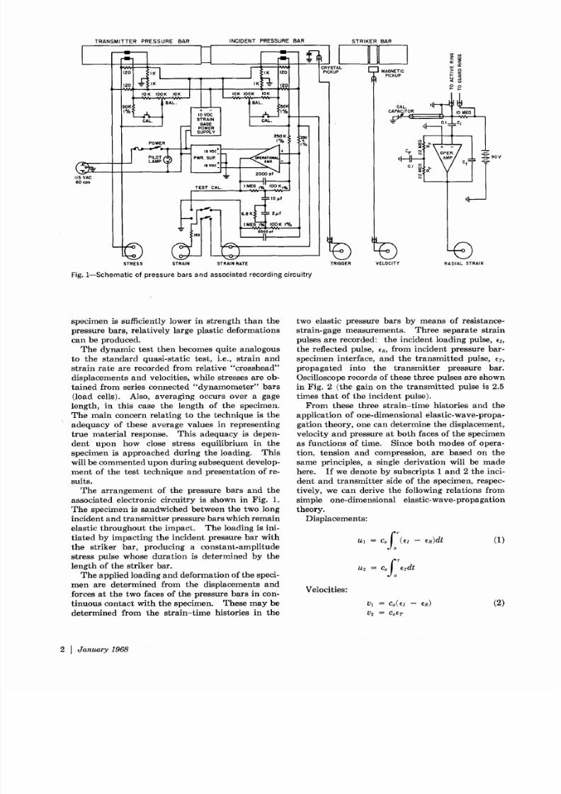
Fig. 1--Schematic of pressure bars and associated recording circuitry
TRIGGER
STRIKER BAR
~ AGNETIC ~ICKUP
l l - - I I - - - ; \ A M P / - L = ~ - -- g o v
,11
VELOCITY RADIAL STRAIN
specimen is sufficiently lower in strength than the
pressure bars, relatively large plastic deformations
can be produced.
The dynamic test then becomes quite analogous
to the standard quasi-static test, i.e., strain and
strain rate are recorded from relative cross head
displacements and velocities, while stresses are ob-
tained from series connected dyna momet er bars
(load cells). Also, ave ragi ng occurs over a gage
length, in this case the length o f the specimen.
The main concern relating to the technique is the
adeq uacy of these a verage values in representing
true material response. This adequacy is depen-
dent: upon how close stress equilibrium in the
specimen is appro ached during the loading. This
will be comment ed upon during subsequent develop-
men t of the test technique and presentati on of re-
sults.
The a rrangement of the pressure bars and the
associated electronic circuitry is shown in Fig. 1.
The specimen is sandwiched between the two long
incident and transmitter pressure bars which remain
elastic thr ough out the impact. The loading is ini-
t iated by impacting the incident pressure bar with
the striker bar, producing a constant-amplitude
stress pulse whose duration is determined by the
length of the striker bar.
The applied loading and deforma tion of the speci-
men are determined from the displacements and
forces at the t wo faces of the pressure bars in con-
tinuous contact with the specimen. These may be
determined from the strain-time histories in the
two elastic pressure bars by means of resistance-
strain-gage measurements . Three separate strain
pulses are recorded: the incid ent loadin g pulse, e~,
the reflected pulse, eR, from incident pressure bar-
specimen interface, and the transmitted pulse, eT,
propagated into the transmitter pressure bar.
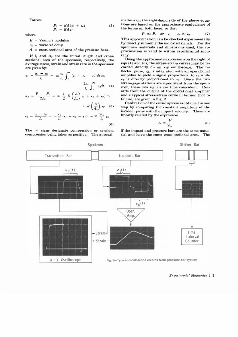
Oscilloscope records of these three pulses are shown
in Fig. 2 (the gain on the transmitted pulse is 2.5
times that of the incident pulse).
From these three strain-time histories and the
application of one-dimensional elastic-wave-propa-
gation theory, one can determine the displacement,
velocity and pressure at both faces of the specimen
as functions of time. Since both mode s of opera-
tion, tension and compression, are based on the
same principles, a single derivation will be made
here. If we denote by subscripts 1 and 2 the inci-
dent and trans mitte r side of the specimen, respec-
tively, we can derive the following relations from
simple one-dimensional elastic-wave-propagation
theory.
Displacements:
Velocities:
f o Tl = C o 4 1 - e R ) d t (1)
f o ~u s = C o e r d t
v l = c o e z - - e R ) (2)
V = C o E T
2 I J a n u a r y 1 9 6 8
8/13/2019 High Strain rate Testing; Tension and Compression.pdf
http://slidepdf.com/reader/full/high-strain-rate-testing-tension-and-compressionpdf 3/9
Forces:
P 1 = E A e ~ + eR) (3)
P ~ = E A e r
where
E = Young s modulu s
co = wave veloci ty
A = cross-sectional area of the pressure bars .
I f lo and A o are the ini tial length and cross-sectional area of the specimen, respectivel y, the
average s t ress , s t ra in and s t ra in ra te in the specimen
are given by:
ul - u~ • Co fres = lo lo ~ -- eR -- e~ )d t
2co e~dt (4)lo
is - v~ - v~ _ ~_ co 2Co
6)
Th e =E s igns designate compression or tension
compress ion be ing taken as pos i t ive . The approx i -
mations on the r ight- hand s ide of the above equa-
t ions are based on the approximate equivalence of
the forces on both faces, so that
PI -~ P2 or el q- e~ er (7)
This approx imat i on can be checked exper iment al ly
by d irect ly summing the indicated s ignals. For the
specimen mater ia l s and d imens ions used, the ap-
proximat ion is val id to wi th in exper imental accu-
racy .Us ing the appro ximat e express ions on the r ight of
eqs (4) and (5), the s tre ss- str ain curves ma y be re-
corded d irect ly on an x - y oscilloscope. The re-
flected pulse, e~, is integrated with an operational
amplifier to yiel d a s ignal propor tion al to es while
eT is direct ly propo rtio nal to as. Since the two
s tra in-gage s ta t ions are equ id is tant f rom the speci-
men, these two signals are t ime coincident. Rec-
ords f rom the outp ut of the ope rat ional ampli fier
and a typ ical s t ress -s t r a in curve in tens ion (not to
failure) are given in Fig. 2.
Cal ibrat ion of the ent i re sys tem is obta ined in one
s tep by compar ing the cons tant ampli tude of the
incident pulse wi th the impact velocity . These arel inear ly re la ted by the express ion
V~ = - - (8)
2co
i f the impac t and pressure bars are the same mate-
rial and have the same cross-sectional area. The
Transmitter Bar
Speci men Str iker Bar
Incident Bar
. tl
-. -Stress
-. -Stra in--
X - Y O scilloscope
ER t)
Time
Interva l
Counter
Fig. 2--Typical oscilloscope records from pressure-bar system
E x p e r i m e n t a l M e c h a n i c s ] 3

8/13/2019 High Strain rate Testing; Tension and Compression.pdf
http://slidepdf.com/reader/full/high-strain-rate-testing-tension-and-compressionpdf 4/9
GuardRings Brass ~ . [--Epoxy
..... Teflon~./~,Z,~,.~/Z,~ /--Suppot Ring
I I ' / l i @ / I i i , I / / ) ' / I
Incident ~ TransmitterPressureBar ~ PressureBar
SupportRing F//,//,~H/,Z/,/../ .~, Y.. fi~/X , ~]
Case Brass ~ ActiveCapacitance ingCompression
[-Specimen
~ \ \ \ \ \ \ \ \ \ \ \ \ \ ]
( . ~ Transmitter I(~ Inc'dent ressureBar ~ Pressure ar /
. . . . . . . . . . . . . . . . F ' /K ~ '4,~ ~ , ' < , ' \ \ \ ' - , - , \ \ \ \ ' - , \ \ t
Tension
Fig. 3--Compression- and tension-specimen configurations
32Rj_n0.5501 '~l-r~---~:.~3 132 - 00. 50
0 80-----~
Fig. 4--Details of tension specimen
/// ~
Initial Loading
a)
Reloading Of
Same Specimen
El -- 2
tRl
O
9 fE Rd t I ' -
= d t
b)
Fig. 5-- a) Typical stress-strain records for 1100-0 aluminumin compression; b) relationship between record and strainamplitudes in pressure bars
impact velocity, V, is measured from the induced-
voltage signal (see Fig. 2) of two fixed grooves on
the striker bar passing a magneti c pickup. The
time interval between the zero crossings of this
signal are recorded on an electronic counter.
The specimen and pressure-bar configurations for
compression and tension are shown in Fig. 3. The
compression specimen is a simple cylinder sand-
wiched between two identical pressure bars. The
diameter of the specimen is smaller than the bars
to allow for radial expansion during plastic defor-
mation. The interface between the specimen and
the bars is lubricated with MoS.2 in order to mini-
mize frictional boun dar y restraint. Concentric with
the compression specimen is shown a capacitance
ring used to measure radial displacement and which
will be described later.
The tensile specimen is hat-shaped, fitting between
a solid cylindrical incident bar and a tubular trans-
mitter bar. Detailed dimensions of this specimen
are given in Fig. 4. Thes e dimensi ons allow use of
incident and tr ansm itte r bars of equal cross-sec-
tiona l area so that eqs (4), (5) and (6) rema in ap-
plicable. Thus, the measuring system is unch anged
for either tension or compression testing. The
actual gage section of the tensile specimen has four
equal arms, each with a length-to-width ratio of
approxi mately 2 to 1. Because of the somewhat
unusua l geometry of the ha t specimen, its static
stress-strain behavior was compared with an ASTM
standard 0.250-in.-diam round tensile-test specimen
of the same material, 1100 = 0 aluminum. Stress-
strain curves for two specimens of each geometry
were found to be coincident up to 30-percent strain,
indicating no significant geometrical effects of the
ha t specimen. Failures in the ha t specimen
occur normally near the midsection. Specimens
which initiate failure at the fillets are discarded.
Some typical oscilloscope records, this time in
compression , are show n in Fig. 5a for 1100 - 0
aluminum. An initial stress- strain curve and a
reloading of the same specimen are shown in order
to illustrate a soft and work-hardened specimen.
Note that the complete unloading curve is traced.
Oscillations, particularly evident in the reloading
curve, are due to Pochammer-Chree ringing in the
pressure bars. Figure 5b shows how all the required
information can be obtained from the stress-strain
4 I Janua ry 968

8/13/2019 High Strain rate Testing; Tension and Compression.pdf
http://slidepdf.com/reader/full/high-strain-rate-testing-tension-and-compressionpdf 5/9
1 6 I [ I I I
1 . 4
1o2
o 1 o lO0 . 8 1 1
0 0 -
c a
0.~
.2
0 , ~ J , 0 2 ,
0.4 0.8 1.2 1.6 2.0 2.4
~], ( )
F ig . 6 - - Ra d i a l s t r a in an d l ong i t ud i na l s t res s v s . l ong i t ud i na ls t r a i n f r om a dy nam i c c om pr e s s i on t es t o f p r e s t r a i ned 1100 -0a l u m i n u m
trace, elimi~ating the time var iable completely.
R a d i a l S t r a i n M e a s u r e m e n t
Wit h the cylindrical compression specimen, radial
s t ra in may be measured d irect ly wi th the coaxial
capaci tance gage shown in Fig. 3. This measure-
ment serves as an independent check on the axial
s t ra in measurement obta ined f rom the pressure
bars . Also, a dynami c Poisson s ratio m ay be
determined f rom the two measurements . The ca-
pacitance gage consists of an active r ing mounted
coaxially inside a heavy brass case with guard rings
on either side. The rings are mou nte d and elec-
t r ical ly iso la ted with an epoxy cement .
An operational amplif ier was used to form a
charge amplif ier for measuring the small capacit ance
change during deforma tion of the specimen. This
circuit is shown in Fig. 1. The guard rings are
charged directly, and the active r ing through a 10-megohm resis tor by a 90-v batter y. A single
capaci tance feedback conver ts the operat i onal am-
plif ier into a charge amplif ier . I t can be shown that
the change in ou tpu t voltage, Ae0, is given by
A V A C ~ ~.~ V A C ~Aeo =
(1 + A ) C ~ + C g C ~
C i > > C f > > C ,, ( 9 )A
A > > I
where
V = vol tag e on gage
Cg = tot al capa citan ce of gage including leads
C ~ C IC x = series combin atio n of C~ and C d C i H - C I
C~ = d-c bloc king cap aci tor
Cf = feedback capac itor
A = gain of opera tion al amplif ier
Hence, the outp ut s ignal is only a funct ion of theappl ied vol tage, V, feedback capaci tance, CI , and
the capaci tance change in the gage. A cal ibrat ion
capaci tor cons is t ing of a push rod with a s teppe d
diameter and a coaxial capaci tance r ing was in-
corporated to make cal ibrat ion easier . The feed-
back network, R r C ~ , is a high-p ass f il ter to give d-c
s tabi l i ty .
The capaci tance between the specimen and the
activ e r ing of the gage can be easily calculated,
neglect ing any smal l amount of f r inging not t aken
care of by the guard rings, by the rela tion
C R = 2 7 re o IR [ l n ; ] - 1 = k ~ [ l n ; R ] - I (10)
where
CR = capaci tance from ring to specimen
e0 = per mit ivi ty of air
l R = length of active r ing
rR = radiu s of active r ing
r = radi us of specimen
Diff ere ntia tin g eq (10) gives
E r ; ~ ]2 d Rd r 1 I n d C R = k ~ -r k l CR ~
Int egr at in g this resu lt over the li mits ro -- r, C~0 -
CR, we get
e~ = ks CR - CRo _ l n r~ ( ACR ~ (11)
C R C ~o r o \ C R o + A C ~ ]
where
e~ = t rue rad ial strai n
ro, C~o = initia l specimen radius an d ini tial r ing
capaci tance
Thus, the ou tpu t of the charge amplif ier (a l inear
function of ACR) is a nonlinear function of s train.
For very small s trains, however, the following ap-
proximat ion may be used:
In r~r
e~ ~ AC R ~12)1
CR O 2 A C R lIlaX)
where
ACR(m~x) = maxim um change in capaci tanc e dur-
ing test.
In the radia l s t ra in tes ts, a record of the out put
of the ca l ibra t ion but ton was a lways taken an d used
E x p e r i m e n t a l M e c h a n i c s t 5

8/13/2019 High Strain rate Testing; Tension and Compression.pdf
http://slidepdf.com/reader/full/high-strain-rate-testing-tension-and-compressionpdf 6/9
as th e calibration for the ACR signal while the initial
capacita nce, CRo was dete rmined from the measure-
men t o f the initial specimen radius, the ring radius,
:and the value of kl. The max imu m strains in most
of the tests were small so tha t t he linear approxima-
tio n of eq (12) could be used. For example, in the
test of Fig. 6, the initial ca pacitanc e was 1.50 pf,
~he maximum change in capacitance was 0.04 pf
so that the maximum error in using eq (12) would
be less tha n 1.5 percent.Figure 6 shows the results of a compression test
on a prestrained 110 0- 0 aluminum specimen
(similar to Fig. 5a), including the radial strain
measurement. The experimental points are plotted
at uniform time increments of 6.5 ~sec below 0.5-
percent strain and 16.3 ~sec above 0.5-percent
strain. Several interesting features can be noted.
For the stress-strain curve, we can follow both the
loadi ng and unloading. Elastic moduli of 107 psi
for aluminum are drawn to indicate the relative ac-
curac y of the results. The experimental loading
modulu s is seen to be considerab ly in error. This is
expected because of the finite time it takes to come
to stress equilibrium across the length of the speci-men through the process of numerous internal wave
reflections. Durin g unloading, the elastic modulus
is in very close agreement, indicating th at the stress
relaxes fairly uniformly over the gage length of the
specimen.
The curve for radial strain, er, vs. longitudinal
strain, et, shows three d istinc t linear regions: the
initial slope during elastic loading which suffers from
the same inaccuracies as the loading modulus, a
slope of 0.50 during plastic defo rmation, a nd an un-
loadi ng elastic slope of 0.32 whic h is close to t he
elastic Poisson s ratio for aluminu m. If we assume
the plastic deformation to be incompressible, the
measured ratio of 0.50 indicates tha t both thecapacitance gage and the pressure bars are accu-
rately measur:ing the deformation.
E l e v a t e d - t e m p e r a t u r e T e s t s
Elevated-temperature tests pose a problem with
the pressure-bar methods in that, if temperature
gradients exist along the leng th of the pressure bars,
the propagation of elastic waves is affected through
the effect of temperatu re on the modulus and the
wave velocit y of the bar material. Since the entire
apparatus is very long, it is impractical to bring the
whole system to an equilibrium temperature. I t
was also found to be impractical to bring the speci-
men alone up to temperature, insert the cold pres-
sure bars, and then perform the impact rapidly.
With this procedure, i t was found from thermo-
couple measurements t hat the rate of heat loss from
the specimen was too rapid, especially in the case
of the tensile specimen, to yield reliable results.
Thus, it became necessary to correct elevated-
temperature data for the temperature gradients in
the pressure bars.
Elevated-temperature tests are performed in the
same manner as just described, with the exception
that a cylindrical, electric-resistance-type oven is
placed symmetrically around the specimen and a
short portion of the pressure bars adj acent to the
specimen. The temp erat ure is controlled from a
thermoc ouple on th e specimen to 5=2 ~ F.
The oven produces temperature gradients in the
incident and transmitter pressure bars which are
rough ly exponentially decreasing with distance from
the specimen and symmetric about the specimen.These gradients have two effects on the elastic
waves: a contin uous change in wave velocity and
a continuous change in amplitude. Since the strain-
gage stations are equidistant from the specimen and
the temperature profile is symmetric, the wave
transit time from the specimen to each gage station
will be the same, i.e., the changes in wave velocity
will not produce error in the recorded signals. The
change in signal amplit ude be tween the gage station
and the specimen, however, must be accounted for.
A correction factor of the form
eo = (1 -k C a 3 / ~) ; C a - - a 2 T - - T o ) (13}
~ al
was derived from previous work 5 on elastic-wave
propagation in a bar with a temperature gradient of
the form
T - T o = T s e - g x ; T > T o
and a l inearly temperature-dependent modulus
E = a l A - a 2 T - T o )
1.30
1.20
i . I 0
oTT 1.00
0.90
0.80
- o
~ Theory
o Exper imental
0 I I I I0 200 400 600 800
Temperature ~
F ig . 7 - - R a t i o o f pa r t i c l e v e l oc i t y a t s t r a i n -gage s t a t i on t o pa r-t i c l e v e l oc i t y a t hea t ed en d ; c om p a r i s on o f t heo r y w i the x p e r i m e n t
1000
6 I J a n u a r y 1 9 6 8
8/13/2019 High Strain rate Testing; Tension and Compression.pdf
http://slidepdf.com/reader/full/high-strain-rate-testing-tension-and-compressionpdf 7/9
F i g 8 S t r e s s s t r a i n c u r v e s
f o r 1 10 0 0 a l u m i n u m i n t e n
s i o n a n d c o m p r e s s i o n
l I I l I
I I 0 0 0 A l u m i n u m
25 20 5 I0
e n s i o n
4
O
12
8
4
5
a: 3.0 x lO-3(sec- )~
I I I I I
I I I I 1
E-- 1 . 8 x l O~ /
F C o m p r e s s i o n
4
8
12
15
20
24
I t I I I
5 I0 15 20 25
S t r a i n ( )
I I I I I 1 2 4
w h e r e
a ~, a 2 a n d K = c o n s t a n t s
To a m b i e n t t e m p e r a t u r e
T ~ . = ( T - T , ) . ~ = o
T h e r a t i o e o / e T i s t h e r a t i o o f t h e s t r a i n r e c o r d e d a tt h e g a g e s ta t i o n , w h i c h i s a t a m b i e n t t e m p e r a t u r e
T o, t o t h e a c t u a l s t r a i n a t t h e s p e c i m e n w h i c h i s a t
t e m p e r a t u r e T .
I n o r d e r t o c h e c k t h e r e l a t i v e a c c u r a c y o f t h i s
c o r r e c t i o n f a c t o r , a s i m p l e e x p e r i m e n t w a s r u n .
T h e e l a s t i c a n d s t r e n g t h p r o p e r t i e s o f t h e b a r m a t e -
r i a l w e r e d e t e r m i n e d . T h e y i e l d s t r e n g t h d e t e r -
m i n e s t h e u p p e r l i m i t o f i m p a c t v e l o c i t y t h a t c a n b e
u s e d a n d a ls o l i m i t s t h e t e m p e r a t u r e r a n g e . T h e
e l a s t ic - w a v e v e l o c i ty w a s m e a s u r e d f r o m w a v e
t r a n s i t t i m e s i n b a r s o f f ix e d l e n g t h a n d u n i f o r m
t e m p e r a t u r e . I n o r d e r t o c h e c k e q 1 3 ), a c o m p a r i -
s o n o f v e l o c i t y ra t h e r t h a n s t r a i n w a s m a d e b e t w e e n
t h e g a g e s t a t i o n o n t h e i n c i d e n t b a r a t r o o m t e m p e r -a t u r e a n d t h e f r e e e n d o f th e i n c i d e n t b a r w h i c h
w a s h e a t e d b y t h e s p e c i m e n ov e n . V e l o c i t y o f t h i s
f re e e n d w a s m e a s u r e d w i t h a c a p a c i t a n c e - t y p e
v e l o c i ty p ic k u p . T h e v e l o c i t y a t th e s t r a i n - g a g e
s t a t i o n i s g i v e n b y th e s t r a i n a m p l i t u d e m u l t i p l i e d
b y t h e e l a s t i c -w a v e s p e ed . T h u s , t h e v e l o c i t y - r a t i o
c o r r e c t i o n i s g i v e n b y
Vo co- 1 + Ca ) ~I4
UT T
A c o m p a r i s o n o f t h i s e x p r e s s i o n w i t h t h e e x p e r i -
m e n t a l r e s u l t s i s g i v e n i n F i g . 7 . T h e c o r r e c t i o n
f a c t o r i s s e e n to b e s m a l l o v e r t h e t e m p e r a t u r e r a n g e
c o n s i d e r e d a n d a g r e e s r e a s o n a b l y w i t h t h e e x p e r i -
m e n t a l d a t a a c t u a l l y i s w i t h i n t h e a c c u r a c y o f t h e
e x p e r i m e n t ) . T h e r e l a t i v e m a g n i t u d e o f t h e co r -r e c t i o n i s i n a g r e e m e n t w i t h C h i d d e s t e r a n d M a l -
v e r n ~ w h o u s e d a m o r e l a b o r i o u s n u m e r i c a l p r o c e-
d u r e . T h i s c o r r e c t i o n f a c t o r h a s b e e n u s e d f o r
e l e v a t e d t e m p e r a t u r e t e s t s t o 7 5 0 ~ F .
R e s u l t s
T e s t s a r e c u r r e n t l y b e i n g p e r f o r m e d o n a l a r g e
n u m b e r o f m e t a l s o f t e c h n i c a l i n t e r e s t . O n l y a f e w
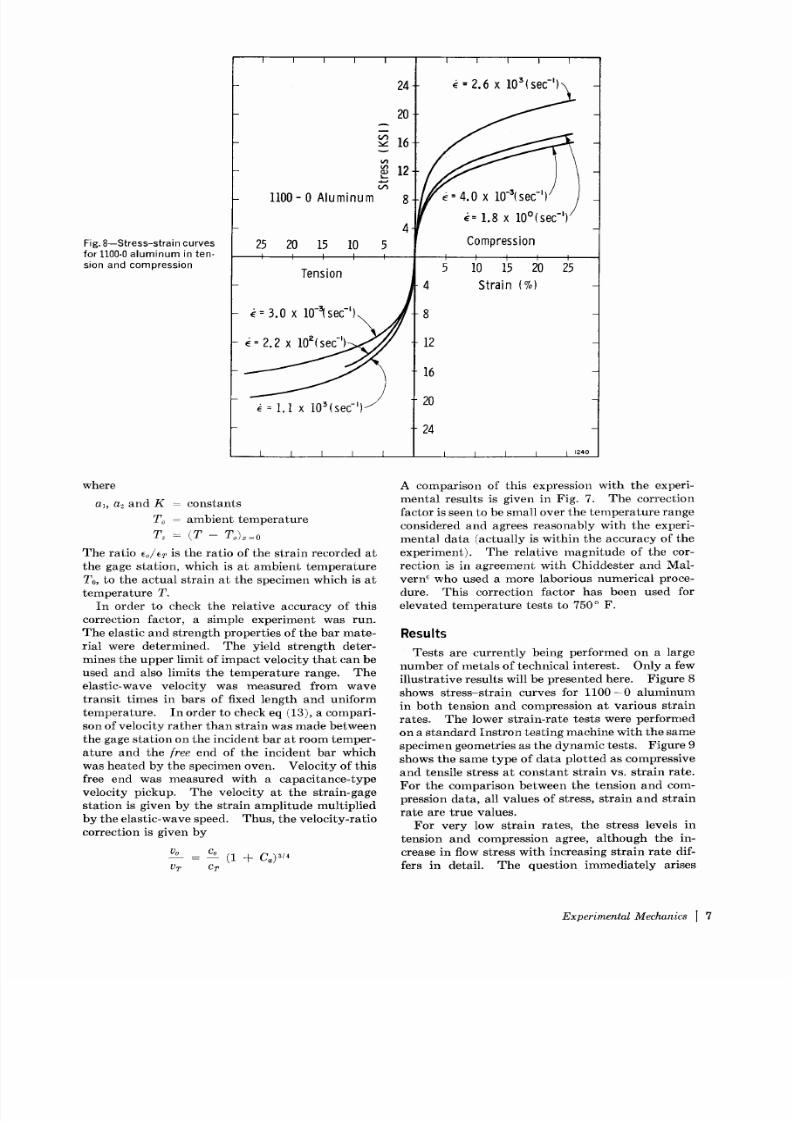
i l l u s t r a t i v e r e s u l t s w il l b e p r e s e n t e d h e r e. F i g u r e 8
s h o w s s t r e s s - s t r a i n c u r v es f o r 1 1 0 0 - 0 a l u m i n u m
i n b o t h t e n s i o n a n d c o m p r e s s i o n a t v a r i o u s s t r a i n
r a t es . T h e l o w e r s t r a i n - r a t e te s t s w e r e p e r f o r m e d
o n a s t a n d a r d I n s t r o n t e s t i n g m a c h i n e w i t h t h e s a m e
s p e c i m e n g e o m e t r i e s a s t h e d y n a m i c t e s t s . F i g u r e 9
s h o w s t h e s a m e t y p e o f d a t a p l o t t e d a s c o m p r e s s i v e
a n d t e n s i l e s t r e s s a t c o n s t a n t s t r a i n v s . s t r a i n r a t e .
F o r t h e c o m p a r i s o n b e t w e e n t h e t e n s i o n a n d c o m -
p r e s s i o n d a t a , a l l v a l u e s o f s tr e s s , s t r a i n a n d s t r a i n
r a t e a r e t r u e v a l u e s .
F o r v e r y l o w s t r a i n r a t e s , t h e s t r e s s le v e l s i n
t e n s i o n a n d c o m p r e s s i o n a g r e e , a l th o u g h t h e i n -
c r e a s e i n f l ow s t r e s s w i t h i n c r e a s i n g s t r a i n r a t e d i f-
f e r s i n d e t a i l . T h e q u e s t i o n i m m e d i a t e l y a r i s e s
E x p e r i m e n t a l M e c h a n i c s I 7
8/13/2019 High Strain rate Testing; Tension and Compression.pdf
http://slidepdf.com/reader/full/high-strain-rate-testing-tension-and-compressionpdf 8/9
A
", I
V')
(I.)~>
em
EO~.)
nV'}v
w..-*(j')
5(--
<D
I---
i 0 - 3 I 0 - 2 i 0 - ' I 0 ~ I 0 ' I 0 z
A v e ra ge S t ra i n R a t e ( s e c - ' )
Fig. 9--Ef fect of strain rate on the fl ow stress of 1100-0 alumi num in tension and compression
1 3
i24
1 4
whether this difference in rate dependence is real or
a funct ion of the tes t and specimen geometry . At
present we must conclude tha t i t is real s ince for
o ther nonrate-sens i t ive metals we obtain the same
s tress -s t ra in curve dynamica l ly or s ta t ical ly . The
difference could result from previous nonisotropic
work hardening of the mater ia l . The specimens
were annea led to 650 o F before testing.
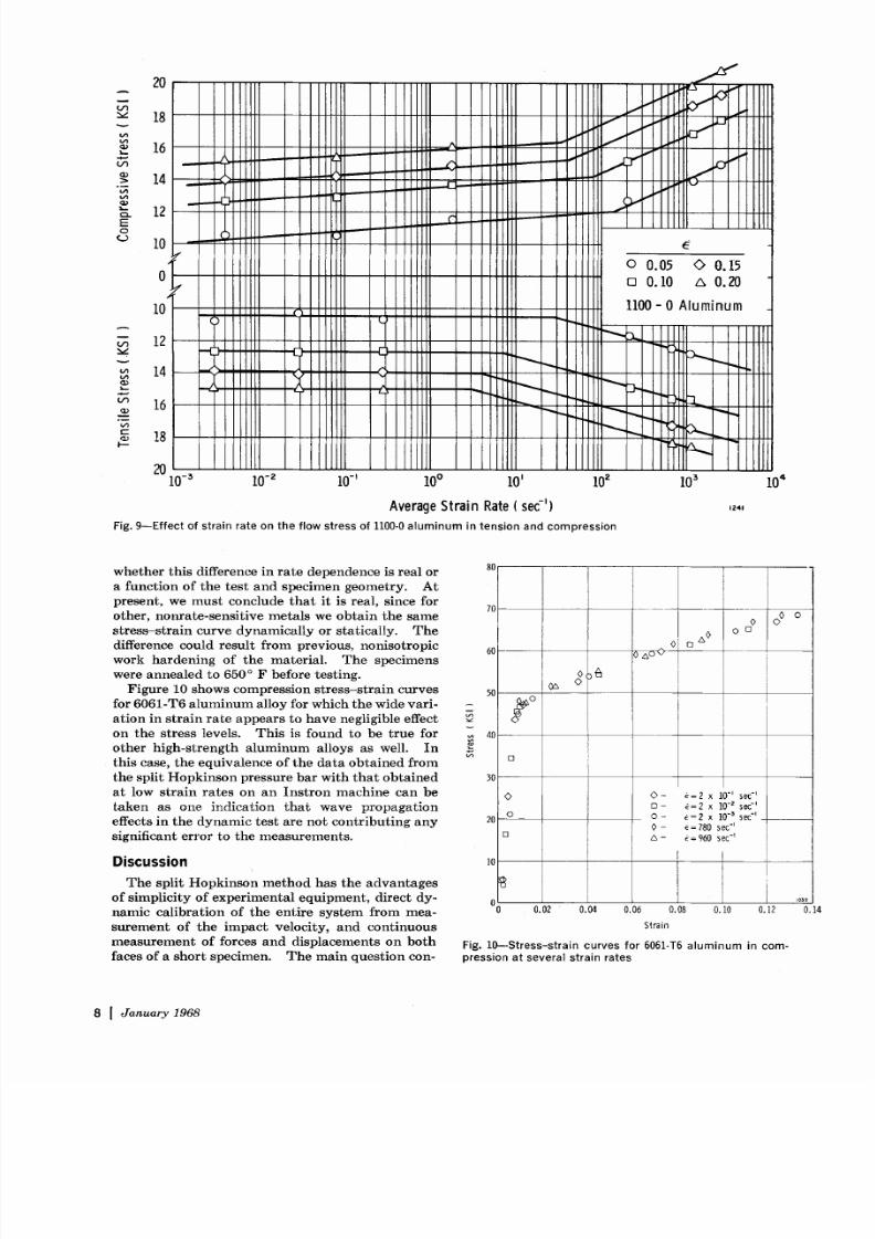
Figure 10 shows compression stress-strain curves
for 6061-T6 a lumi num alloy for which the wide vari-
a t ion in s t ra in ra te appears to have neglig ib le ef fect
on the s tress levels. This is found to be true for
o ther h igh-s t rength a luminum al loys as wel l. In
this case the equivalence of the d ata obta ined from
the sp l i t Hopkinson pressure bar wi th that obta ined
at low s t ra in ra tes on an Ins t ron machine can be
taken as one indicat ion that wave propagat ion
effects in the dy namic tes t are not c ontr ibut ing any
significant error to the measurem ents .
D i s c u s s i o n
The spl i t Hopkinson method has the advant ages
of s impl ic i ty of exper imental equipment d i rect dy-
namic cal ibra t i on of the ent i re sys tem f rom mea-
surement of the impact veloci ty and cont inuous
measurement of forces and d isp lacements on both
faces of a short specimen. The mai n question con-
80
60
5O
o ~40
[]
30
20
~o0 0 c]
O O
<>
O
[]
O- E=2 X I0 ~ sec l
[3 - ~= 2 x 10 z sec-'
9 ,~ =2 x 10 5 sec ~
0 E=780 see-'
A- t=960sec ~
i o
o I ]0 0.02 0.04 0.06 0.08 0.10 0.12
Strain
F ig . 1 0 S t r e s s s t r a i n c u r v e s f o r 60 6 1 T 6 a l u m i n u m i n c o m
p r e s s i o n a t s e v e r a l s t r a i n r a t e s
4 ~
O 14
8 I J a n u a r y 9 6 8
8/13/2019 High Strain rate Testing; Tension and Compression.pdf
http://slidepdf.com/reader/full/high-strain-rate-testing-tension-and-compressionpdf 9/9