High-strain, high-strain-rate flow and failure in …meyersgroup.ucsd.edu/papers/journals/Meyers...
8
Materials Science and Engineering A 472 (2008) 308–315 High-strain, high-strain-rate flow and failure in PTFE/Al/W granular composites J. Cai a , S.M. Walley b , R.J.A. Hunt b , W.G. Proud b , V.F. Nesterenko a , M.A. Meyers a,∗ a Department of Mechanical and Aerospace Engineering, University of California, San Diego, La Jolla, CA 92093-0411, USA b Cavendish Laboratory, University of Cambridge, Cambridge CB3 0HE, UK Received 20 January 2007; received in revised form 8 March 2007; accepted 15 March 2007 Abstract Dynamic compression experiments were performed on a pressed PTFE/Al/W mixture to understand the composite behavior at high-strain and high-strain rate. The high-strain-rate tests were carried out in a drop-weight apparatus at impact velocities of 3.5 and 5 m/s, providing strain rates of approximately 4 × 10 2 s −1 . Aluminum jackets of varying thickness were used to ensure that specimens underwent confined deformation but did not separate into fragments. Failure was preceded by extensive plastic deformation concentrated primarily in the PTFE component. W particle–PTFE interface separation provided initiation and propagation of cracks. In extensively deformed specimens (strains of up to −0.875), PTFE nanofibers formed along cracks as a result of shear localization and significant softening caused by plastic deformation. The Zerilli–Armstrong constitutive equation for polymeric solids was used to simulate the response of the composite. Its use is justified by the fact that the majority of plastic strain is concentrated in the PTFE polymer. © 2007 Elsevier B.V. All rights reserved. Keywords: Drop-weight; High-strain; High-strain-rate deformation; PTFE; Al; W; Polymer composites 1. Introduction Non-detonating reactive materials are being intensively stud- ied for projectile applications in military operations in urban terrain (MOUT). The requirements are a high density and exothermic reaction initiation upon impact. This paper is con- cerned with PTFE/Al/W granular materials that underwent high-strain, high-strain-rate deformation in drop-weight tests. The primary function of W is to increase the density of the mixture and for low collateral damage, although it may also participate in the exothermic reactions with Al. Al and PTFE are known to react exothermically [1]. While granular materials are widespread, extensive research on their physics just started a few decades and the properties of complex granular materials remain unexplored so far. The considerable interest in granu- lar materials is due to phenomena they exhibit in applications: segregation, fluidization, stress propagation, etc. [2–4]. For gran- ular powder mixtures, the primary focus is on the kinetics of chemical reactions. Two classes of reactions were proposed by ∗ Corresponding author. Tel.: +1 858 534 4719; fax: +1 858 534 5698. E-mail address: [email protected] (M.A. Meyers). Thadhani [5] to explain the dynamic effects: shock-assisted reac- tions have been defined as those occurring in the time scale of thermal equilibration (tens of microseconds to milliseconds), while shock-induced reactions are those occurring in the time scale of pressure equilibration (nano- to micro-second dura- tion) in shock-loading. Meyers et al. [6] and Vecchio et al. [7] investigated Mo–Si and Nb–Si mixtures subjected to shock com- pression and proposed a mechanism for reaction initiation. This shock reaction was modeled by Eakins et al. [8]. The dynamic properties and shock behavior of a few poly- mers, such as PTFE, Estane TM , Kel-F-800 TM , polychloroprene, PMMA and epoxy resin, have been investigated to serve as the binder materials [9–12]. PTFE and Kel-F-800 TM exhibited constant shear strength behind the shock front, while other poly- meric systems showed increased shear strength, a characteristic attributed to the viscoelastic/viscoplastic properties. The shear strengths of PTFE and estane TM increased with the increase of impact stress, while that of Kel-F-800 TM had a constant strength. Teflon (PTFE) was also studied as an inert granular material under dynamic compaction [13] and explosive loading [14,15]. PTFE is an outstanding candidate as the binder material due to a favorable combination of properties: low friction coef- ficient, high thermal stability, high electrical resistance, high 0921-5093/$ – see front matter © 2007 Elsevier B.V. All rights reserved. doi:10.1016/j.msea.2007.03.068
Transcript of High-strain, high-strain-rate flow and failure in …meyersgroup.ucsd.edu/papers/journals/Meyers...
A
hasifei©
K
1
itechTmpaaarlsuc
0d
Materials Science and Engineering A 472 (2008) 308–315
High-strain, high-strain-rate flow and failure inPTFE/Al/W granular composites
J. Cai a, S.M. Walley b, R.J.A. Hunt b, W.G. Proud b, V.F. Nesterenko a, M.A. Meyers a,∗a Department of Mechanical and Aerospace Engineering, University of California, San Diego, La Jolla, CA 92093-0411, USA
b Cavendish Laboratory, University of Cambridge, Cambridge CB3 0HE, UK
Received 20 January 2007; received in revised form 8 March 2007; accepted 15 March 2007
bstract
Dynamic compression experiments were performed on a pressed PTFE/Al/W mixture to understand the composite behavior at high-strain andigh-strain rate. The high-strain-rate tests were carried out in a drop-weight apparatus at impact velocities of 3.5 and 5 m/s, providing strain rates ofpproximately 4 × 10² s−1. Aluminum jackets of varying thickness were used to ensure that specimens underwent confined deformation but did noteparate into fragments. Failure was preceded by extensive plastic deformation concentrated primarily in the PTFE component. W particle–PTFEnterface separation provided initiation and propagation of cracks. In extensively deformed specimens (strains of up to −0.875), PTFE nanofibers
ormed along cracks as a result of shear localization and significant softening caused by plastic deformation. The Zerilli–Armstrong constitutivequation for polymeric solids was used to simulate the response of the composite. Its use is justified by the fact that the majority of plastic strains concentrated in the PTFE polymer. 2007 Elsevier B.V. All rights reserved.W; P
Tttwstips
mPtcma
eywords: Drop-weight; High-strain; High-strain-rate deformation; PTFE; Al;
. Introduction
Non-detonating reactive materials are being intensively stud-ed for projectile applications in military operations in urbanerrain (MOUT). The requirements are a high density andxothermic reaction initiation upon impact. This paper is con-erned with PTFE/Al/W granular materials that underwentigh-strain, high-strain-rate deformation in drop-weight tests.he primary function of W is to increase the density of theixture and for low collateral damage, although it may also
articipate in the exothermic reactions with Al. Al and PTFEre known to react exothermically [1]. While granular materialsre widespread, extensive research on their physics just startedfew decades and the properties of complex granular materials
emain unexplored so far. The considerable interest in granu-ar materials is due to phenomena they exhibit in applications:
egregation, fluidization, stress propagation, etc. [2–4]. For gran-lar powder mixtures, the primary focus is on the kinetics ofhemical reactions. Two classes of reactions were proposed by∗ Corresponding author. Tel.: +1 858 534 4719; fax: +1 858 534 5698.E-mail address: [email protected] (M.A. Meyers).
siTu
tfi
921-5093/$ – see front matter © 2007 Elsevier B.V. All rights reserved.oi:10.1016/j.msea.2007.03.068
olymer composites
hadhani [5] to explain the dynamic effects: shock-assisted reac-ions have been defined as those occurring in the time scale ofhermal equilibration (tens of microseconds to milliseconds),hile shock-induced reactions are those occurring in the time
cale of pressure equilibration (nano- to micro-second dura-ion) in shock-loading. Meyers et al. [6] and Vecchio et al. [7]nvestigated Mo–Si and Nb–Si mixtures subjected to shock com-ression and proposed a mechanism for reaction initiation. Thishock reaction was modeled by Eakins et al. [8].
The dynamic properties and shock behavior of a few poly-ers, such as PTFE, EstaneTM, Kel-F-800TM, polychloroprene,MMA and epoxy resin, have been investigated to serve as
he binder materials [9–12]. PTFE and Kel-F-800TM exhibitedonstant shear strength behind the shock front, while other poly-eric systems showed increased shear strength, a characteristic
ttributed to the viscoelastic/viscoplastic properties. The sheartrengths of PTFE and estaneTM increased with the increase ofmpact stress, while that of Kel-F-800TM had a constant strength.eflon (PTFE) was also studied as an inert granular material
nder dynamic compaction [13] and explosive loading [14,15].PTFE is an outstanding candidate as the binder material dueo a favorable combination of properties: low friction coef-cient, high thermal stability, high electrical resistance, high
d Engineering A 472 (2008) 308–315 309
ceEad
rtdfitms
2
pf9P
7otwb
Goivi
FPo
J. Cai et al. / Materials Science an
hemical inertness, high melting point (327 ◦C), high thermalnergy release when decomposed, and the easiness to deform.xperiments show that the addition of PTFE into Ti/Si mixturend Fe2O3/Al mixture increased the magnitude of reaction andecreased the reaction time [16].
The purpose of this research is to investigate mechanicalesponse, including fracture mechanism, of a PTFE/Al/W mix-ure under high-strain and high-strain-rate flow. Therefore, therop-weight technique was adopted, since the weight has suf-cient energy to subject the specimens to large strains. This
echnique was used in the investigation of high-strain-rate defor-ation behavior of polymers [17] and thermites [18], and in the
ensitivity testing of explosive substances [19].
. Experimental techniques
The PTFE/Al/W composite was fabricated by cold uniaxialressing at a pressure of 100 MPa. The initial powders had theollowing average sizes: Al: 2 and 95 �m (ValimeH-2 and H-5); W: 44 �m (Teledyne, −325 mesh); PTFE: 100 nm (DuPont,TFE 9002-84-0, type MP 1500J).
The mixture had the following weight content of components:7 wt% W, 17.5 wt% PTFE, and 5.5 wt% Al. The final densityf the pressed mixture was 95% of the theoretical density. Dueo the large difference in density between the constituents, PTFEas the major component on a volume fraction, 56%, followedy Al, 23% and W, 21%.
The drop-weight test apparatus at the Physics of Solidsroup, Cavendish Laboratory [17,20], was used. The schematic
f the apparatus is shown in Fig. 1; the specimen was mountedn a sample holder that ensured the parallelism of impact. Theelocity of the drop-weight decreases as a function of time aftermpact.ig. 1. Schematic drawing of the experimental set-up for drop-weight test. ,TFE/Al/W mixture specimen; , confinement Al ring; , sample holder forptimum alignment; , drop weight; �, strain gage.
Ftt
c7At
cd(agfssriirs
sa
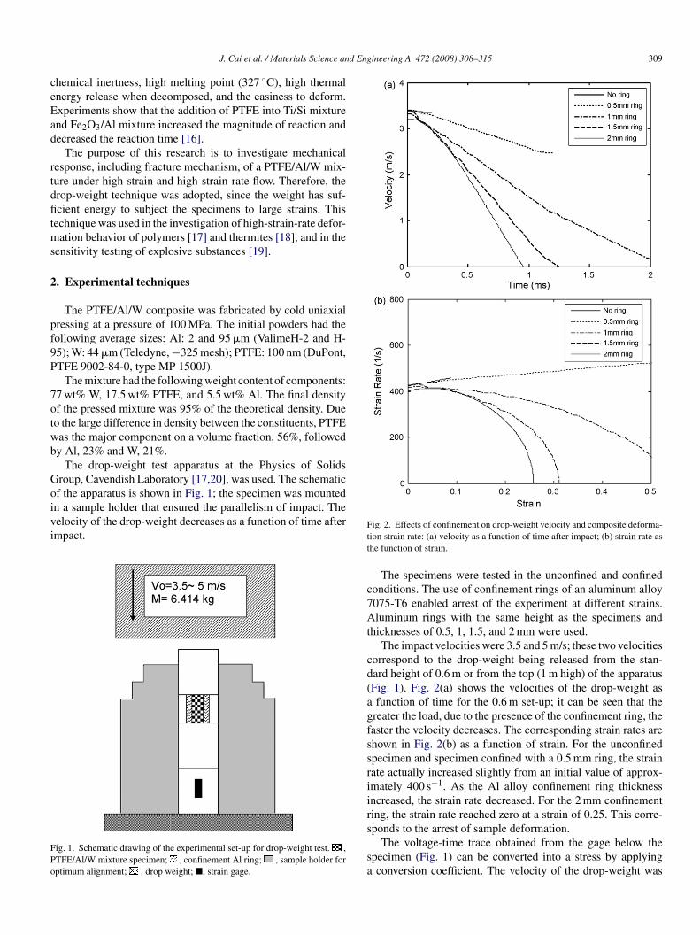
ig. 2. Effects of confinement on drop-weight velocity and composite deforma-ion strain rate: (a) velocity as a function of time after impact; (b) strain rate ashe function of strain.
The specimens were tested in the unconfined and confinedonditions. The use of confinement rings of an aluminum alloy075-T6 enabled arrest of the experiment at different strains.luminum rings with the same height as the specimens and
hicknesses of 0.5, 1, 1.5, and 2 mm were used.The impact velocities were 3.5 and 5 m/s; these two velocities
orrespond to the drop-weight being released from the stan-ard height of 0.6 m or from the top (1 m high) of the apparatusFig. 1). Fig. 2(a) shows the velocities of the drop-weight asfunction of time for the 0.6 m set-up; it can be seen that the
reater the load, due to the presence of the confinement ring, theaster the velocity decreases. The corresponding strain rates arehown in Fig. 2(b) as a function of strain. For the unconfinedpecimen and specimen confined with a 0.5 mm ring, the strainate actually increased slightly from an initial value of approx-mately 400 s−1. As the Al alloy confinement ring thicknessncreased, the strain rate decreased. For the 2 mm confinementing, the strain rate reached zero at a strain of 0.25. This corre-
ponds to the arrest of sample deformation.The voltage-time trace obtained from the gage below thepecimen (Fig. 1) can be converted into a stress by applyingconversion coefficient. The velocity of the drop-weight was
3 and E
mIos
utl
3
3
Tbb
Fm
Ff(fisaa(
3
F
10 J. Cai et al. / Materials Science
easured and this was used for the determination of the strain.n this manner it was possible to obtain the stress-strain responsef the specimen/confinement ring assembly. The procedures aretandard and therefore will not be presented here.
For photography, an AWRE C4 rotating-mirror camera wassed [21]. It has 140 framing lenses, giving a total recordingime of approximately 1 ms. The records were used to probe theocalization of failure in unconfined specimens.
. Results and discussion
.1. Initial microstructure
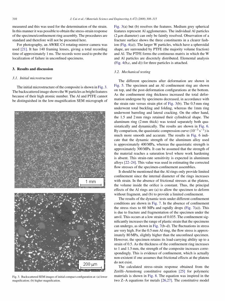
The initial microstructure of the composite is shown in Fig. 3.he backscattered image shows the W particles as bright featuresecause of their high atomic number. The Al and PTFE cannote distinguished in the low-magnification SEM micrograph of
ig. 3. Backscattered SEM images of initial compact configuration at: (a) loweragnification; (b) higher magnification.
oAmtuutasBmciatiafl
cwtew
ctiancaiHstsnd
Zmt
ngineering A 472 (2008) 308–315
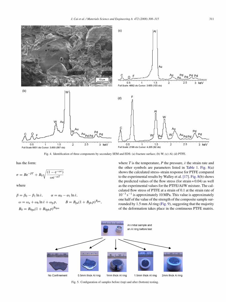
ig. 3(a) but (b) resolves the features. Medium grey sphericaleatures represent Al agglomerates. The individual Al particles2 �m diameter) can only be faintly resolved. Observation of aracture surface shows the three constituents in a clearer fash-on (Fig. 4(a)). The larger W particles, which have a spheroidalhape, are surrounded by PTFE (the majority volume fraction)nd Al. The PTFE forms the continuous matrix in which the Wnd Al particles are discretely distributed. Elemental analysisFig. 4(b,c, and d)) for three particles is attached.
.2. Mechanical testing
The different specimens after deformation are shown inig. 5. The specimen and an Al confinement ring are shownn top, and the post-deformation configurations at the bottom.s the confinement ring thickness increased the total defor-ation undergone by specimens decreased, in accordance with
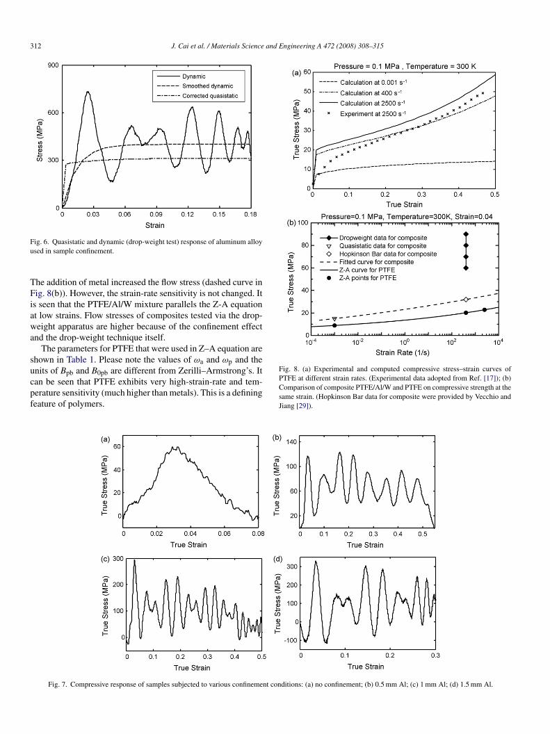
he strain rate versus strain plot of Fig. 3(b). The 0.5 mm ringnderwent total buckling and folding, whereas the 1mm ringnderwent barreling and lateral cracking. On the other hand,he 1.5 and 2 mm rings retained their cylindrical shape. Theluminum ring (2 mm thick) was tested separately both qua-istatically and dynamically. The results are shown in Fig. 6.y comparison, the quasistatic compression curve (10−3 s−1) isuch more smooth and accurate. The results in Fig. 6 indi-
ate that the dynamic strength of the aluminum alloy useds approximately 400 MPa, whereas the quasistatic strength ispproximately 300 MPa. It can be assumed that the strength ofhe material reaches a saturation level where work hardenings absent. This strain-rate sensitivity is expected in aluminumlloys [22–24]. This value was used in estimating the correctedow stresses of the specimen-confinement assemblies.
It should be mentioned that the Al rings only provide limitedonfinement since the internal diameter of the rings increasesith strain. In the absence of frictional stresses at the platens,
he volume inside the orifice is constant. Thus, the principalffects of the Al rings are (a) to allow the specimen to deformithout fragment, and (b) to provide a limited confinement.The results of the dynamic tests under different confinement
onditions are shown in Fig. 7. In the absence of confinementhe stress rises to 60 MPa and rapidly drops (Fig. 7(a)). Thiss due to fracture and fragmentation of the specimen under thenvil. This occurs at a low strain of 0.035. The confinement sig-ificantly increases the range of plastic strain that the specimensan undergo, as shown in Fig. 7(b–d). The fluctuations in stressre very high. For the 0.5 mm Al ring, the flow stress is approx-mately 80 MPa, slightly higher than the unconfined specimen.owever, the specimen retains its load-carrying ability up to a
train of 0.5. As the thickness of the confinement ring increaseso 1 and 1.5 mm, the strength of the composite increases corre-pondingly. This is evidence of confinement, which is actuallyon-existent if one assumes that frictional effects at the platenso not exist.
The calculated stress–strain response obtained from theerilli–Armstrong constitutive equation [25] for polymericaterials is shown in Fig. 8. The equation was inspired in the
wo Z–A equations for metals [26,27]. The constitutive model
J. Cai et al. / Materials Science and Engineering A 472 (2008) 308–315 311
SEM
h
σ
w
β
wtsttac
Fig. 4. Identification of three components by secondary
as the form:
= Be−βT + B0
√(1 − e−ωε)
ωe−αT
here
= β0 − β1 ln ε̇, α = α0 − α1 ln ε̇,
ω = ωa + ωb ln ε̇ + ωpp, B = Bpa(1 + Bpbp)Bpm ,
B0 = B0pa(1 + B0pbp)B0pm
1oro
Fig. 5. Configuration of samples before
and EDS: (a) fracture surface; (b) W; (c) Al; (d) PTFE.
here T is the temperature, P the pressure, ε̇ the strain rate andhe other symbols are parameters listed in Table 1. Fig. 8(a)hows the calculated stress–strain response for PTFE comparedo the experimental results by Walley et al. [17]. Fig. 8(b) showshe predicted values of the flow stress (for strain = 0.04) as wells the experimental values for the PTFE/Al/W mixture. The cal-ulated flow stress of PTFE at a strain of 0.1 at the strain rate of
0−3 s−1 is approximately 10 MPa. This value is approximatelyne half of the value of the strength of the composite sample sur-ounded by 1.5 mm Al ring (Fig. 9), suggesting that the majorityf the deformation takes place in the continuous PTFE matrix.(top) and after (bottom) testing.
312 J. Cai et al. / Materials Science and Engineering A 472 (2008) 308–315
Fu
TFiawa
sucpf
Fig. 8. (a) Experimental and computed compressive stress–strain curves of
ig. 6. Quasistatic and dynamic (drop-weight test) response of aluminum alloysed in sample confinement.
he addition of metal increased the flow stress (dashed curve inig. 8(b)). However, the strain-rate sensitivity is not changed. It
s seen that the PTFE/Al/W mixture parallels the Z-A equationt low strains. Flow stresses of composites tested via the drop-eight apparatus are higher because of the confinement effect
nd the drop-weight technique itself.The parameters for PTFE that were used in Z–A equation are
hown in Table 1. Please note the values of ωa and ωp and thenits of Bpb and B0pb are different from Zerilli–Armstrong’s. It
an be seen that PTFE exhibits very high-strain-rate and tem-erature sensitivity (much higher than metals). This is a definingeature of polymers.PTFE at different strain rates. (Experimental data adopted from Ref. [17]); (b)Comparison of composite PTFE/Al/W and PTFE on compressive strength at thesame strain. (Hopkinson Bar data for composite were provided by Vecchio andJiang [29]).
Fig. 7. Compressive response of samples subjected to various confinement conditions: (a) no confinement; (b) 0.5 mm Al; (c) 1 mm Al; (d) 1.5 mm Al.
J. Cai et al. / Materials Science and Engineering A 472 (2008) 308–315 313
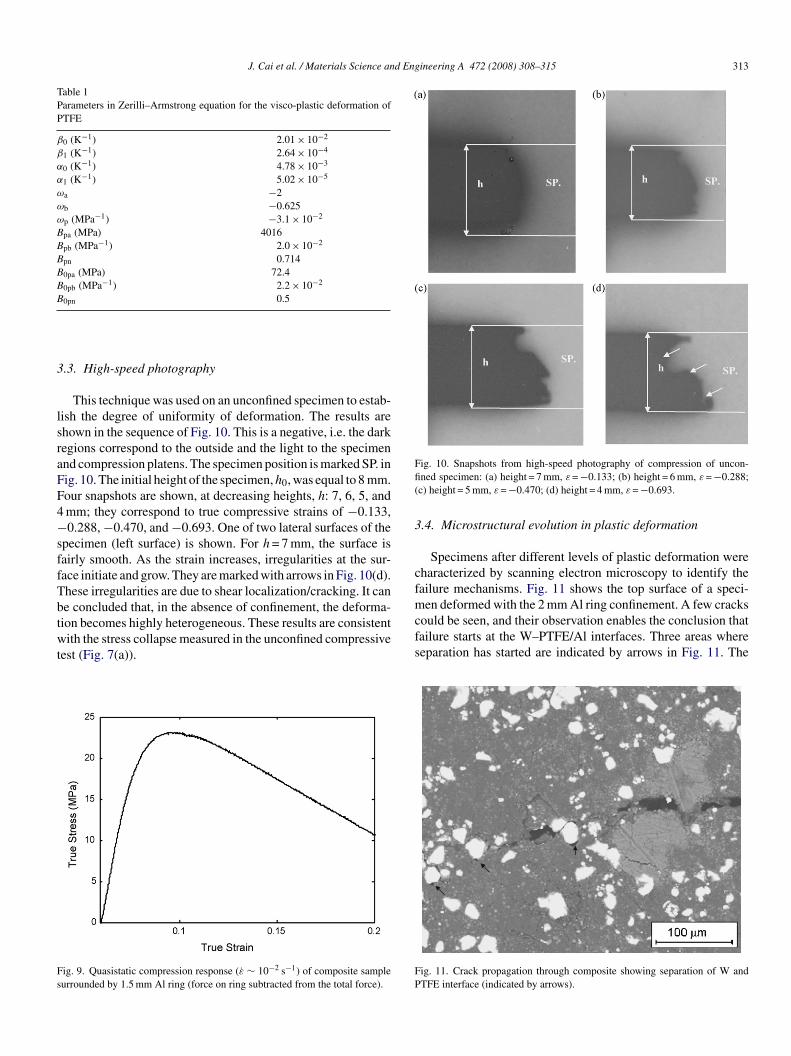
Table 1Parameters in Zerilli–Armstrong equation for the visco-plastic deformation ofPTFE
β0 (K−1) 2.01 × 10⁻²
β1 (K−1) 2.64 × 10⁻⁴
α0 (K−1) 4.78 × 10⁻³
α1 (K−1) 5.02 × 10⁻⁵
ωa −2ωb −0.625ωp (MPa−1) −3.1 × 10⁻²
Bpa (MPa) 4016Bpb (MPa−1) 2.0 × 10⁻²
Bpn 0.714B0pa (MPa) 72.4B0pb (MPa−1) 2.2 × 10⁻²
B 0.5
3
lsraFF4−sffTbtwt
Fs
Ffi(
3
cfmcould be seen, and their observation enables the conclusion thatfailure starts at the W–PTFE/Al interfaces. Three areas whereseparation has started are indicated by arrows in Fig. 11. The
0pn
.3. High-speed photography
This technique was used on an unconfined specimen to estab-ish the degree of uniformity of deformation. The results arehown in the sequence of Fig. 10. This is a negative, i.e. the darkegions correspond to the outside and the light to the specimennd compression platens. The specimen position is marked SP. inig. 10. The initial height of the specimen, h0, was equal to 8 mm.our snapshots are shown, at decreasing heights, h: 7, 6, 5, andmm; they correspond to true compressive strains of −0.133,0.288, −0.470, and −0.693. One of two lateral surfaces of the
pecimen (left surface) is shown. For h = 7 mm, the surface isairly smooth. As the strain increases, irregularities at the sur-ace initiate and grow. They are marked with arrows in Fig. 10(d).hese irregularities are due to shear localization/cracking. It cane concluded that, in the absence of confinement, the deforma-ion becomes highly heterogeneous. These results are consistentith the stress collapse measured in the unconfined compressive
est (Fig. 7(a)).
ig. 9. Quasistatic compression response (ε̇ ∼ 10−2 s−1) of composite sampleurrounded by 1.5 mm Al ring (force on ring subtracted from the total force).
FP
ig. 10. Snapshots from high-speed photography of compression of uncon-ned specimen: (a) height = 7 mm, ε = −0.133; (b) height = 6 mm, ε = −0.288;c) height = 5 mm, ε = −0.470; (d) height = 4 mm, ε = −0.693.
.4. Microstructural evolution in plastic deformation
Specimens after different levels of plastic deformation wereharacterized by scanning electron microscopy to identify theailure mechanisms. Fig. 11 shows the top surface of a speci-en deformed with the 2 mm Al ring confinement. A few cracks
ig. 11. Crack propagation through composite showing separation of W andTFE interface (indicated by arrows).
314 J. Cai et al. / Materials Science and E
F
strpstolAT
atwroisapdiPmeeiitca
4
Pru
(
(
(
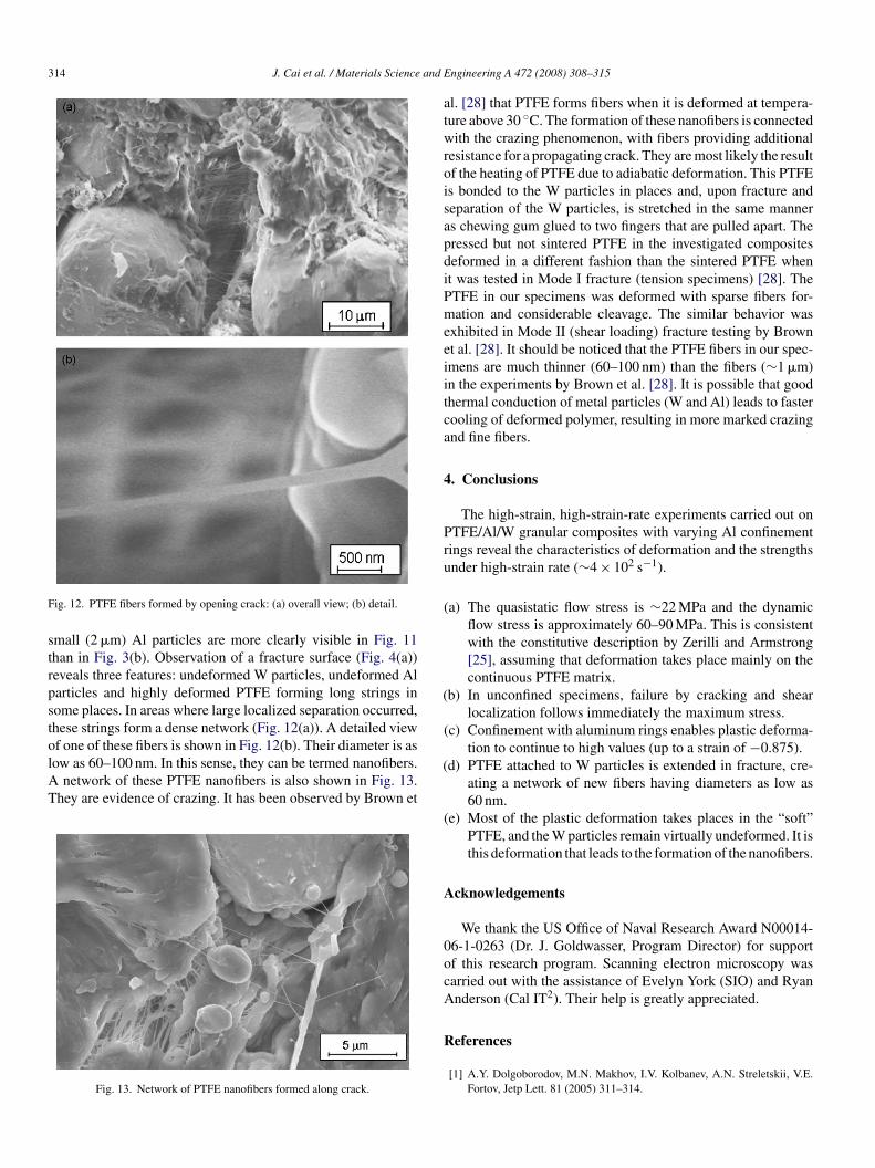
ig. 12. PTFE fibers formed by opening crack: (a) overall view; (b) detail.
mall (2 �m) Al particles are more clearly visible in Fig. 11han in Fig. 3(b). Observation of a fracture surface (Fig. 4(a))eveals three features: undeformed W particles, undeformed Alarticles and highly deformed PTFE forming long strings inome places. In areas where large localized separation occurred,hese strings form a dense network (Fig. 12(a)). A detailed view
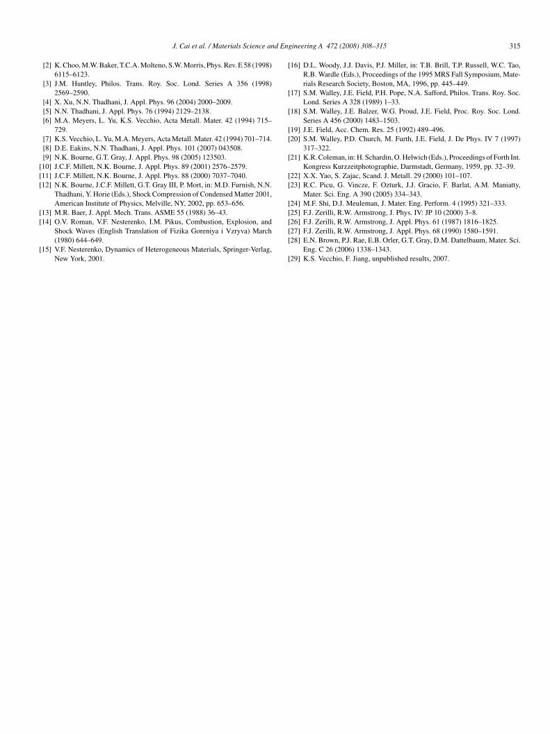
f one of these fibers is shown in Fig. 12(b). Their diameter is asow as 60–100 nm. In this sense, they can be termed nanofibers.network of these PTFE nanofibers is also shown in Fig. 13.hey are evidence of crazing. It has been observed by Brown et
Fig. 13. Network of PTFE nanofibers formed along crack.
(
(
A
0ocA
R
ngineering A 472 (2008) 308–315
l. [28] that PTFE forms fibers when it is deformed at tempera-ure above 30 ◦C. The formation of these nanofibers is connectedith the crazing phenomenon, with fibers providing additional
esistance for a propagating crack. They are most likely the resultf the heating of PTFE due to adiabatic deformation. This PTFEs bonded to the W particles in places and, upon fracture andeparation of the W particles, is stretched in the same manners chewing gum glued to two fingers that are pulled apart. Theressed but not sintered PTFE in the investigated compositeseformed in a different fashion than the sintered PTFE whent was tested in Mode I fracture (tension specimens) [28]. TheTFE in our specimens was deformed with sparse fibers for-ation and considerable cleavage. The similar behavior was
xhibited in Mode II (shear loading) fracture testing by Brownt al. [28]. It should be noticed that the PTFE fibers in our spec-mens are much thinner (60–100 nm) than the fibers (∼1 �m)n the experiments by Brown et al. [28]. It is possible that goodhermal conduction of metal particles (W and Al) leads to fasterooling of deformed polymer, resulting in more marked crazingnd fine fibers.
. Conclusions
The high-strain, high-strain-rate experiments carried out onTFE/Al/W granular composites with varying Al confinementings reveal the characteristics of deformation and the strengthsnder high-strain rate (∼4 × 10² s−1).
a) The quasistatic flow stress is ∼22 MPa and the dynamicflow stress is approximately 60–90 MPa. This is consistentwith the constitutive description by Zerilli and Armstrong[25], assuming that deformation takes place mainly on thecontinuous PTFE matrix.
b) In unconfined specimens, failure by cracking and shearlocalization follows immediately the maximum stress.
c) Confinement with aluminum rings enables plastic deforma-tion to continue to high values (up to a strain of −0.875).
d) PTFE attached to W particles is extended in fracture, cre-ating a network of new fibers having diameters as low as60 nm.
e) Most of the plastic deformation takes places in the “soft”PTFE, and the W particles remain virtually undeformed. It isthis deformation that leads to the formation of the nanofibers.
cknowledgements
We thank the US Office of Naval Research Award N00014-6-1-0263 (Dr. J. Goldwasser, Program Director) for supportf this research program. Scanning electron microscopy wasarried out with the assistance of Evelyn York (SIO) and Ryannderson (Cal IT2). Their help is greatly appreciated.
eferences
[1] A.Y. Dolgoborodov, M.N. Makhov, I.V. Kolbanev, A.N. Streletskii, V.E.Fortov, Jetp Lett. 81 (2005) 311–314.
d Eng
[[[
[[
[
[
[
[
[[
[
[[
[[
J. Cai et al. / Materials Science an
[2] K. Choo, M.W. Baker, T.C.A. Molteno, S.W. Morris, Phys. Rev. E 58 (1998)6115–6123.
[3] J.M. Huntley, Philos. Trans. Roy. Soc. Lond. Series A 356 (1998)2569–2590.
[4] X. Xu, N.N. Thadhani, J. Appl. Phys. 96 (2004) 2000–2009.[5] N.N. Thadhani, J. Appl. Phys. 76 (1994) 2129–2138.[6] M.A. Meyers, L. Yu, K.S. Vecchio, Acta Metall. Mater. 42 (1994) 715–
729.[7] K.S. Vecchio, L. Yu, M.A. Meyers, Acta Metall. Mater. 42 (1994) 701–714.[8] D.E. Eakins, N.N. Thadhani, J. Appl. Phys. 101 (2007) 043508.[9] N.K. Bourne, G.T. Gray, J. Appl. Phys. 98 (2005) 123503.10] J.C.F. Millett, N.K. Bourne, J. Appl. Phys. 89 (2001) 2576–2579.11] J.C.F. Millett, N.K. Bourne, J. Appl. Phys. 88 (2000) 7037–7040.12] N.K. Bourne, J.C.F. Millett, G.T. Gray III, P. Mort, in: M.D. Furnish, N.N.
Thadhani, Y. Horie (Eds.), Shock Compression of Condensed Matter 2001,American Institute of Physics, Melville, NY, 2002, pp. 653–656.
13] M.R. Baer, J. Appl. Mech. Trans. ASME 55 (1988) 36–43.
14] O.V. Roman, V.F. Nesterenko, I.M. Pikus, Combustion, Explosion, andShock Waves (English Translation of Fizika Goreniya i Vzryva) March(1980) 644–649.
15] V.F. Nesterenko, Dynamics of Heterogeneous Materials, Springer-Verlag,New York, 2001.
[[[
[
ineering A 472 (2008) 308–315 315
16] D.L. Woody, J.J. Davis, P.J. Miller, in: T.B. Brill, T.P. Russell, W.C. Tao,R.B. Wardle (Eds.), Proceedings of the 1995 MRS Fall Symposium, Mate-rials Research Society, Boston, MA, 1996, pp. 445–449.
17] S.M. Walley, J.E. Field, P.H. Pope, N.A. Safford, Philos. Trans. Roy. Soc.Lond. Series A 328 (1989) 1–33.
18] S.M. Walley, J.E. Balzer, W.G. Proud, J.E. Field, Proc. Roy. Soc. Lond.Series A 456 (2000) 1483–1503.
19] J.E. Field, Acc. Chem. Res. 25 (1992) 489–496.20] S.M. Walley, P.D. Church, M. Furth, J.E. Field, J. De Phys. IV 7 (1997)
317–322.21] K.R. Coleman, in: H. Schardin, O. Helwich (Eds.), Proceedings of Forth Int.
Kongress Kurzzeitphotographie, Darmstadt, Germany, 1959, pp. 32–39.22] X.X. Yao, S. Zajac, Scand. J. Metall. 29 (2000) 101–107.23] R.C. Picu, G. Vincze, F. Ozturk, J.J. Gracio, F. Barlat, A.M. Maniatty,
Mater. Sci. Eng. A 390 (2005) 334–343.24] M.F. Shi, D.J. Meuleman, J. Mater. Eng. Perform. 4 (1995) 321–333.25] F.J. Zerilli, R.W. Armstrong, J. Phys. IV: JP 10 (2000) 3–8.
26] F.J. Zerilli, R.W. Armstrong, J. Appl. Phys. 61 (1987) 1816–1825.27] F.J. Zerilli, R.W. Armstrong, J. Appl. Phys. 68 (1990) 1580–1591.28] E.N. Brown, P.J. Rae, E.B. Orler, G.T. Gray, D.M. Dattelbaum, Mater. Sci.Eng. C 26 (2006) 1338–1343.29] K.S. Vecchio, F. Jiang, unpublished results, 2007.