HIGH SPEED TOUCH SCREEN ASSEMBLY USING … speed touch screen assembly using . anisotropic...
4
HIGH SPEED TOUCH SCREEN ASSEMBLY USING ANISOTROPIC CONDUCTIVE ADHESIVES (ACAS) VERTICAL ULTRASONIC BONDING METHOD Kyung-Wook Paik, Seung-Ho Kim, and Kiwon Lee Nano Packaging and Interconnect Lab. (NPIL) Department of Materials Science and Engineering Korea Advanced Institute of Science and Technology (KAIST) Daejeon, Korea [email protected] ABSTRACT A novel anisotropic conductive film (ACF) bonding process using ultrasonic vibration was investigated in touch screen panel(TSP)-on-board (TOB) applications. The ACF temperature increased as the U/S power increased and the bonding pressure decreased. The ACF temperature was successfully controlled by adjusting both U/S power and bonding pressure. The significant meaning of this result is that the ACF bonding process can be remarkably improved by U/S bonding compared with conventional T/C bonding. Using the optimized U/S bonding parameters, the ACF interconnects showed significantly less thermal damages to PET substrates and similar bonding performances as T/C bonding in terms of the contact resistance and the adhesion strength. And the cure degree of adhesive resin was achieved 90 % at 3 sec. In terms of thermal deformation, U/S bonding showed no severe thermal deformation of TSPs up to 120 o C which is much higher than T g of PET substrates. This result indicates that ACA can be heated up to 120 o C without severe thermal deformation of the PET substrates by VUS. It is presumably due to the rapid heating rate and the short bonding time of VUS bonding. As a summary, the VUS method can be successfully used in touch screen assembly with high speed and good reliability. Key words: touch screen panels, ACA, vertical unltrsonic bonding, assembly ULTRASONIC ACA BONDING TECHNOLOGY For ACF interconnection, thermo-compression (T/C) bonding is the most common method, however it is necessary to reduce the bonding temperature, time and pressure, because T/C bonding is often limited by high bonding temperature, slow thermal cure, uneven cure degree of adhesive, large thermal deformation of the assembly. Therefore, there are constant needs of lower bonding temperature and faster cure ACF bonding to replace the conventional T/C bonding. Ultrasonic (U/S) bonding is one of alternative processes for ACF interconnection which have been suggested by Lee et al. [7][8]. In U/S bonding, ACFs can be rapidly heated by certain ultrasonic vibration, and it can be described by materials’ complex young’s modulus which consists of storage modulus and loss modulus under cyclic stress conditions. Storage modulus relates to elastically stored energy, and loss modulus relates to energy loss which converts to heat. In general, it is well known that visco-elastic materials such as polymers have large loss modulus. Therefore, it is expected that highly visco-elastic B-stage ACFs may generate a large amount of heat by ultrasonic vibration. As a result, the ACF layer can be rapidly heated and cured without additional chip/substrate heating. Fig. 1 shows the schematic of an ultrasonic ACA bonder. Fig. 1 Schematic and real photo of an ultrasonic ACA bonder with a converter, booster, and horn. ACF temperature can be precisely controlled by the ultrasonic vibration amplitude as shown in the Fig. 2, FOB(Flex on Board) samples. Fig. 2 ACF temperatures heated by the various ultrasonic vibration in FOB samples 0 2 4 6 8 0 50 100 150 200 250 300 ACF temeprature ( o C) Bonding time (sec) Relative U/S vibration 10% 20% 30% 40% 50% 60% Booste Chip or substrate 1 Substrate 2 U/S horn Local heat generation Converter Controller Power Control Ultrasonic Vibration Amplify vibration Transfer U/S Vibration to sample Heat Generation As originally published in the Pan Pacific Symposium Proceedings.
Transcript of HIGH SPEED TOUCH SCREEN ASSEMBLY USING … speed touch screen assembly using . anisotropic...
HIGH SPEED TOUCH SCREEN ASSEMBLY USING ANISOTROPIC CONDUCTIVE ADHESIVES (ACAS)
VERTICAL ULTRASONIC BONDING METHOD
Kyung-Wook Paik, Seung-Ho Kim, and Kiwon Lee Nano Packaging and Interconnect Lab. (NPIL)
Department of Materials Science and Engineering Korea Advanced Institute of Science and Technology (KAIST)
Daejeon, Korea [email protected]
ABSTRACT A novel anisotropic conductive film (ACF) bonding process using ultrasonic vibration was investigated in touch screen panel(TSP)-on-board (TOB) applications. The ACF temperature increased as the U/S power increased and the bonding pressure decreased. The ACF temperature was successfully controlled by adjusting both U/S power and bonding pressure. The significant meaning of this result is that the ACF bonding process can be remarkably improved by U/S bonding compared with conventional T/C bonding. Using the optimized U/S bonding parameters, the ACF interconnects showed significantly less thermal damages to PET substrates and similar bonding performances as T/C bonding in terms of the contact resistance and the adhesion strength. And the cure degree of adhesive resin was achieved 90 % at 3 sec. In terms of thermal deformation, U/S bonding showed no severe thermal deformation of TSPs up to 120 oC which is much higher than Tg of PET substrates. This result indicates that ACA can be heated up to 120 oC without severe thermal deformation of the PET substrates by VUS. It is presumably due to the rapid heating rate and the short bonding time of VUS bonding. As a summary, the VUS method can be successfully used in touch screen assembly with high speed and good reliability. Key words: touch screen panels, ACA, vertical unltrsonic bonding, assembly ULTRASONIC ACA BONDING TECHNOLOGY For ACF interconnection, thermo-compression (T/C) bonding is the most common method, however it is necessary to reduce the bonding temperature, time and pressure, because T/C bonding is often limited by high bonding temperature, slow thermal cure, uneven cure degree of adhesive, large thermal deformation of the assembly. Therefore, there are constant needs of lower bonding temperature and faster cure ACF bonding to replace the conventional T/C bonding. Ultrasonic (U/S) bonding is one of alternative processes for ACF interconnection which have been suggested by Lee et al. [7][8]. In U/S bonding, ACFs can be rapidly heated by certain ultrasonic vibration, and it can be described by materials’ complex young’s modulus which consists of storage modulus and loss modulus under cyclic stress conditions. Storage modulus relates to elastically stored energy, and loss modulus relates to energy loss
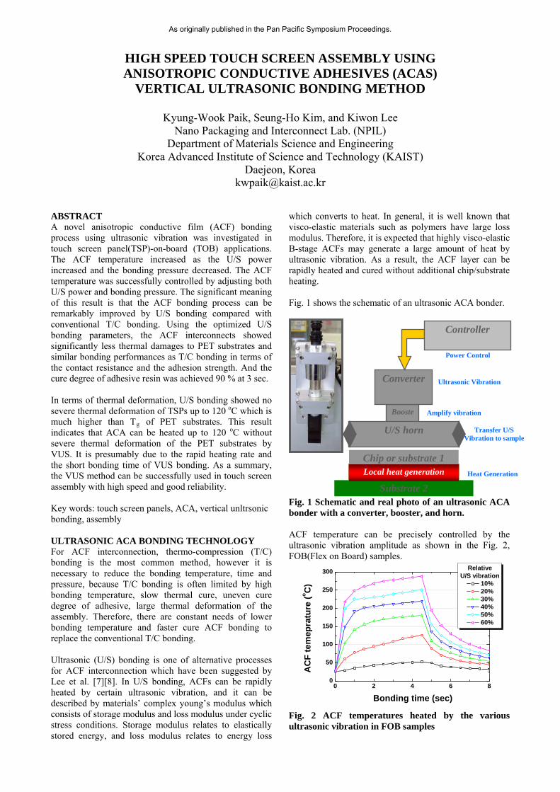
which converts to heat. In general, it is well known that visco-elastic materials such as polymers have large loss modulus. Therefore, it is expected that highly visco-elastic B-stage ACFs may generate a large amount of heat by ultrasonic vibration. As a result, the ACF layer can be rapidly heated and cured without additional chip/substrate heating. Fig. 1 shows the schematic of an ultrasonic ACA bonder.
Fig. 1 Schematic and real photo of an ultrasonic ACA bonder with a converter, booster, and horn. ACF temperature can be precisely controlled by the ultrasonic vibration amplitude as shown in the Fig. 2, FOB(Flex on Board) samples.
Fig. 2 ACF temperatures heated by the various ultrasonic vibration in FOB samples
0 2 4 6 80
50
100
150
200
250
300
AC
F t
em
epra
ture
(oC
)
Bonding time (sec)
RelativeU/S vibration
10% 20% 30% 40% 50% 60%
Booste
Chip or substrate 1
Substrate 2
U/S horn
Local heat generation
Converter
Controller
Power Control
Ultrasonic Vibration
Amplify vibration
Transfer U/S Vibration to sample
Heat Generation
As originally published in the Pan Pacific Symposium Proceedings.
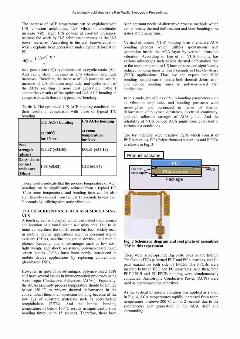
The increase of ACF temperature can be explained with U/S vibration amplitudes. U/S vibration amplitudes increase with larger U/S powers at constant pressures, because the work by U/S vibration increases as the U/S power increases. According to the well-known equation which explains heat generation under cyclic deformation [9],
2
'')( 2 EfdQ
heat generation (dQ) is proportional to cyclic strain (Δε). And cyclic strain increases as U/S vibration amplitude increases. Therefore, the increase of U/S power causes the increase of U/S vibration amplitude, and cyclic strain of the ACFs resulting in more heat generation. Table 1 summarizes results of the optimized U/S ACF bonding in comparison with those of typical T/C bonding. Table 1. The optimized U/S ACF bonding condition and their results in comparison with those of typical T/C bonding.
T/C ACFs bonding
at 190℃
for 15 sec
U/S ACFs bonding at room temperature for 3 sec
Peel strength (gf/cm)
622.47 (±28.59) 633.41 (±52.14)
Daisy-chain contact resistance (Ohm)
1.08 (±0.02) 1.13 (±0.04)
These results indicate that the process temperature of ACF bonding can be significantly reduced from a typical 190
oC to room temperature, and bonding time can be also significantly reduced from typical 15 seconds to less than 5 seconds by utilizing ultrasonic vibration. TOUCH SCREEN PANEL ACA ASSEMBLY USING VUS A touch screen is a display which can detect the presence and location of a touch within a display area. Due to its intuitive interface, the touch screen has been widely used in mobile device applications such as personal digital assistant (PDA), satellite navigation devices, and mobile phones. Recently, due to advantages such as low cost, light weigh, and shock resistance, polymer-based touch screen panels (TSPs) have been newly introduced in mobile device applications by replacing conventional glass-based TSPs. However, in spite of its advantages, polymer-based TSPs still have several issues in interconnection processes using Anisotropic Conductive Adhesives (ACAs). Especially, the ACAs assembly process temperature should be limited below 150 oC to prevent thermal deformation in the conventional thermo-compression bonding because of the low Tgs of substrate materials such as polyethylene terephthalates (PETs). And the limited bonding temperature of below 150 oC results in significantly slow bonding times up to 15 seconds. Therefore, there have
been constant needs of alternative process methods which can eliminate thermal deformation and slow bonding time issues at the same time. Vertical ultrasonic (VUS) bonding is an alternative ACA bonding process which utilizes spontaneous heat generation inside the ACA layer by vertical ultrasonic vibration. According to Lee et al, VUS bonding has various advantages such as less thermal deformation due to the room temperature US horn process and significantly reduced bonding times within 3 seconds in Flex-On-Board (FOB) applications. Thus, we can expect that VUS bonding method can eliminate both thermal deformation and reduce bonding times in polymer-based TSP applications. In this study, the effects of VUS bonding parameters such as vibration amplitudes and bonding pressures were investigated and optimized in terms of thermal deformation of polymer substrates, electrical continuity, and pull adhesion strength of ACA joints. And the reliability of VUS bonded ACA joints were evaluated at various test conditions. The test vehicles were resistive TSPs which consist of PET substrates, PC (Polycarbonate) substrates and FPCBs as shown in Fig. 3.
Fig. 3 Schematic diagram and real photo of assembled TSP in this experiment There were screen-printed Ag paste pads on the Indium Tin Oxide (ITO) patterned PET and PC substrates, and Cu pads existed on both side of FPCB. The FPCBs were inserted between PET and PC substrates. And then, both PET-FPCB and PC-FPCB bonding were simultaneously conducted. Anisotropic Conductive Pastes (ACPs) were used as interconnection adhesives. As the vertical ultrasonic vibration was applied as shown in Fig. 4, ACA temperatures rapidly increased from room temperature to above 200 oC within 2 seconds due to the spontaneous heat generation in the ACA itself and surrounding.
Package
Product package
PET
PC(poly carbonate) Double stick tape
FPCB
As originally published in the Pan Pacific Symposium Proceedings.
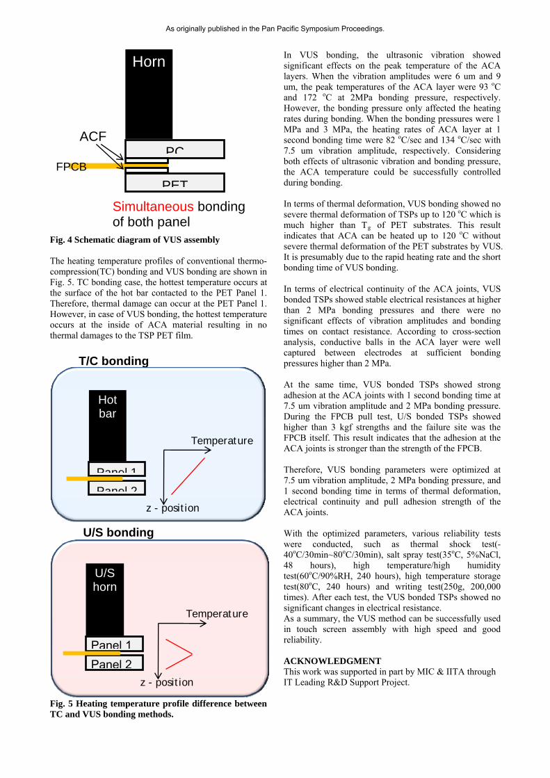
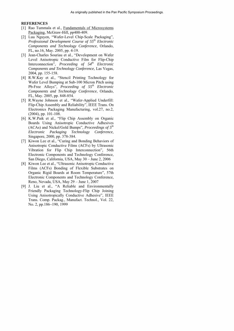
Fig. 4 Schematic diagram of VUS assembly The heating temperature profiles of conventional thermo-compression(TC) bonding and VUS bonding are shown in Fig. 5. TC bonding case, the hottest temperature occurs at the surface of the hot bar contacted to the PET Panel 1. Therefore, thermal damage can occur at the PET Panel 1. However, in case of VUS bonding, the hottest temperature occurs at the inside of ACA material resulting in no thermal damages to the TSP PET film.
Fig. 5 Heating temperature profile difference between TC and VUS bonding methods.
In VUS bonding, the ultrasonic vibration showed significant effects on the peak temperature of the ACA layers. When the vibration amplitudes were 6 um and 9 um, the peak temperatures of the ACA layer were 93 oC and 172 oC at 2MPa bonding pressure, respectively. However, the bonding pressure only affected the heating rates during bonding. When the bonding pressures were 1 MPa and 3 MPa, the heating rates of ACA layer at 1 second bonding time were 82 oC/sec and 134 oC/sec with 7.5 um vibration amplitude, respectively. Considering both effects of ultrasonic vibration and bonding pressure, the ACA temperature could be successfully controlled during bonding. In terms of thermal deformation, VUS bonding showed no severe thermal deformation of TSPs up to 120 oC which is much higher than Tg of PET substrates. This result indicates that ACA can be heated up to 120 oC without severe thermal deformation of the PET substrates by VUS. It is presumably due to the rapid heating rate and the short bonding time of VUS bonding. In terms of electrical continuity of the ACA joints, VUS bonded TSPs showed stable electrical resistances at higher than 2 MPa bonding pressures and there were no significant effects of vibration amplitudes and bonding times on contact resistance. According to cross-section analysis, conductive balls in the ACA layer were well captured between electrodes at sufficient bonding pressures higher than 2 MPa. At the same time, VUS bonded TSPs showed strong adhesion at the ACA joints with 1 second bonding time at 7.5 um vibration amplitude and 2 MPa bonding pressure. During the FPCB pull test, U/S bonded TSPs showed higher than 3 kgf strengths and the failure site was the FPCB itself. This result indicates that the adhesion at the ACA joints is stronger than the strength of the FPCB. Therefore, VUS bonding parameters were optimized at 7.5 um vibration amplitude, 2 MPa bonding pressure, and 1 second bonding time in terms of thermal deformation, electrical continuity and pull adhesion strength of the ACA joints. With the optimized parameters, various reliability tests were conducted, such as thermal shock test(-40oC/30min~80oC/30min), salt spray test(35oC, 5%NaCl, 48 hours), high temperature/high humidity test(60oC/90%RH, 240 hours), high temperature storage test(80oC, 240 hours) and writing test(250g, 200,000 times). After each test, the VUS bonded TSPs showed no significant changes in electrical resistance. As a summary, the VUS method can be successfully used in touch screen assembly with high speed and good reliability. ACKNOWLEDGMENT This work was supported in part by MIC & IITA through IT Leading R&D Support Project.
PET
PC
Horn
ACF
FPCB
Simultaneous bonding of both panel
T/C bonding
Panel 2
Panel 1
Hot bar
Temperature
z - position
U/S bonding
U/S horn
Temperature
z - position
R bb
U/S horn
Temperature
Panel 1Panel 2
z - position
As originally published in the Pan Pacific Symposium Proceedings.
REFERENCES [1] Rao Tummala et al., Fundamentals of Microsystems
Packaging, McGraw-Hill, pp400-409. [2] Luu Nguyen, “Wafer-Level Chip-Scale Packaging”,
Professional Development Course of 55th Electronic Components and Technology Conference, Orlando, FL, no.16, May. 2005, pp. 4-19.
[3] Jean-Charles Souriau et al., “Development on Wafer Level Anisotropic Conductive Film for Flip-Chip Interconnection”, Proceeding of 54th Electronic Components and Technology Conference, Las Vegas, 2004, pp. 155-158.
[4] R.W.Kay et al., “Stencil Printing Technology for Wafer Level Bumping at Sub-100 Micron Pitch using Pb-Free Alloys”, Proceeding of 55th Electronic Components and Technology Conference, Orlando, FL, May. 2005, pp. 848-854.
[5] R.Wayne Johnson et al., “Wafer-Applied Underfill: Flip-Chip Assembly and Reliability”, IEEE Trans. On Electronics Packaging Manufacturing, vol.27, no.2, (2004), pp. 101-108.
[6] K.W.Paik et al., “Flip Chip Assembly on Organic Boards Using Anisotropic Conductive Adhesives (ACAs) and Nickel/Gold Bumps”, Proceedings of 5th Electronic Packaging Technology Conference, Singapore, 2000, pp. 378-384.
[7] Kiwon Lee et al., “Curing and Bonding Behaviors of Anisotropic Conductive Films (ACFs) by Ultrasonic Vibration for Flip Chip Interconnection”, 56th Electronic Components and Technology Conference, San Diego, California, USA, May 30 – June 2, 2006
[8] Kiwon Lee et al., “Ultrasonic Anisotropic Conductive Films (ACFs) Bonding of Flexible Substrates on Organic Rigid Boards at Room Temperature”, 57th Electronic Components and Technology Conference, Reno, Nevada, USA, May 29 – June 1, 2007
[9] J. Liu et al., “A Reliable and Environmentally Friendly Packaging Technology-Flip Chip Joining Using Anisotropically Conductive Adhesive”, IEEE Trans. Comp. Packag., Manufact. Technol., Vol. 22, No. 2, pp.186~190, 1999
As originally published in the Pan Pacific Symposium Proceedings.