High Speed Narrow Groove Submerged Arc Welding for … · NSRP Report High Speed Narrow Groove...
151
November 30, 2005 EWI Project No. 48565GTH ATI Subcontract Agreement No. 2005-365 NSRP Report High Speed Narrow Groove Submerged Arc Welding for Thin Steel Panels Government Purpose Rights DISTRIBUTION STATEMENT A. Approved for public release; distribution is unlimited. Revised: December 5, 2005 Submitted to: Advanced Technology Institute Charleston, SC
Transcript of High Speed Narrow Groove Submerged Arc Welding for … · NSRP Report High Speed Narrow Groove...

November 30, 2005
EWI Project No. 48565GTH ATI Subcontract Agreement No. 2005-365
NSRP Report
High Speed Narrow Groove Submerged Arc Welding for
Thin Steel Panels
Government Purpose Rights
DISTRIBUTION STATEMENT A. Approved for public release; distribution is unlimited.
Revised: December 5, 2005
Submitted to:
Advanced Technology Institute Charleston, SC

Report
Project No. 48565GTH ATI Subcontract Agreement No. 2005-365
on
High Speed Narrow Groove Submerged Arc Welding for Thin Steel Panels
to
Advanced Technology Institute Charleston, SC
Government Purpose Rights
DISTRIBUTION STATEMENT A. Approved for public release; distribution is unlimited.
November 30, 2005 Revised: December 5, 2005
Final Revision
Brian Baughman, Jim Russell, Chris Conrardy, and Nancy Porter Edison Welding Institute
1250 Arthur E. Adams Drive Columbus, OH 43221
Nick Evans and Lee Kvidahl
Northrop Grumman Ship Systems P.O. Box 149
Pascagoula, MS 39568
Harry Sadler and Dave Barton The Lincoln Electric Company
22801 St. Clair Avenue Cleveland, OH 44117

48565GTH/R-1/05 iii
Contents Page
Executive Summary ....................................................................................................................viii
1. 0 Introduction ........................................................................................................................... 1
2. 0 Background........................................................................................................................... 1
3. 0 Objectives ............................................................................................................................. 2
4. 0 Technical Approach .............................................................................................................. 2 4.1 Existing Process Evaluation ................................................................................................2 4.2 Tooling and Fixturing Development..................................................................................... 3 4.3 Procedure Development......................................................................................................3 4.4 Process Demonstration ....................................................................................................... 4
5. 0 Results and Discussions....................................................................................................... 4 5.1 Existing Modified S-SAW Process Assessment.................................................................. 4 5.2 Tooling and Fixturing Development................................................................................... 11 5.3 Tandem SAW Procedure Development ............................................................................ 13
5.3.1 Overview..................................................................................................................... 13 5.3.2 Equipment and Set-up ................................................................................................ 14 5.3.3 Materials ..................................................................................................................... 16 5.3.4 Original FCB Groove Design Procedure Development and Results........................... 17
5.3.4.1 Analysis of High-Speed Tandem SAW Process with Original FCB Groove......... 20 5.3.4.2 Consultation with The Lincoln Electric Company ................................................. 20
5.3.5 Improved FCB Groove Design Procedure Development and Results ........................ 21 5.3.5.1 5-mm Procedure .................................................................................................. 22 5.3.5.2 8-mm Procedure .................................................................................................. 26 5.3.5.3 10-mm Procedure ................................................................................................ 29 5.3.5.4 Distortion Measurements ..................................................................................... 31 5.3.5.5 Procedure Qualification........................................................................................ 37 5.3.5.6 Thick Section Welding with 8-mm Procedures..................................................... 39 5.3.5.7 Analysis of High-Speed Tandem SAW with Improved FCB Groove .................... 39
5.4 Process Demonstration ..................................................................................................... 42 5.5 Financial Considerations ...................................................................................................44
6. 0 Conclusions ........................................................................................................................ 45
7. 0 Recommendations .............................................................................................................. 46
8. 0 References.......................................................................................................................... 47
9. 0 Acronyms ............................................................................................................................ 48
Appendix A – Original FCB Groove Design Welding Parameters............................................... 49
Appendix B – Improved FCB Groove Design Weld Parameters................................................. 54
Appendix C – DC Offset Trends ................................................................................................. 58

48565GTH/R-1/05 iv
Appendix D – ROMER Arm Distortion Measurements: 5-mm Before Weld................................ 59
Appendix E – ROMER Arm Distortion Measurements: 5-mm After Weld................................... 67
Appendix F – ROMER Arm Distortion Measurements: 8-mm Before Weld ................................ 75
Appendix G – ROMER Arm Distortion Measurements: 8-mm After Weld .................................. 83
Appendix H – ROMER Arm Distortion Measurements: 10-mm Before Weld.............................. 91
Appendix I – ROMER Arm Distortion Measurements 10-mm After Weld ................................... 99
Appendix J – Data Acquisition Measurements for 5-mm Procedures....................................... 107
Appendix K – Data Acquisition Measurements for 8-mm Procedures ...................................... 112
Appendix L – Data Acquisition Measurements for 10-mm Procedures .................................... 118
Appendix M – Thick Section Welding with Developed Procedures .......................................... 125
Appendix N – Project Results Presentation .............................................................................. 126
48565GTH/R-1/05 v
Figures Page
Figure 1 - Electrode Configuration of Modified S-SAW Process................................................... 5 Figure 2 - Top View of NGSS - Pascagoula Panel Line Fixture ................................................... 6 Figure 3 - Side view of Pascagoula Panel Line Fixture ................................................................ 7 Figure 4 - Dimensions of Original FCB Bar Design Used by Pascagoula .................................... 8 Figure 5 - Modified S-SAW Weld 5-mm Plate............................................................................... 9 Figure 6 - Modified S-SAW Weld 8-mm Plate............................................................................. 10 Figure 7 - Modified S-SAW Weld 10-mm Plate........................................................................... 10 Figure 8 - Mock-up Plate Positioned in EWI Fixture ................................................................... 11 Figure 9 - EWI Fixture with FCB Bar Centered........................................................................... 12 Figure 10 - Electrical Grounding Arrangement on Improved FCB Bar........................................ 12 Figure 11 - Tandem SAW Torch Positioning .............................................................................. 13 Figure 12 - Tandem SAW Work Area at EWI ............................................................................. 14 Figure 13 - Waveform Variables Used in Tandem SAW Development....................................... 16 Figure 14 - Weld with Typical Root Bead Suck-Back ................................................................. 18 Figure 15 - Inconsistent Suck-Back Defects on Welds Made with Identical Parameters............ 19 Figure 16 - Welds with Pronounced Suck-Back in the Middle Span........................................... 19 Figure 17 - Lincoln Recommended FCB Groove for 5-mm Square Butt Joints .......................... 21 Figure 18 - Lincoln Recommended FCB Groove for 8- and 10-mm Square Butt Joints ............. 21 Figure 19 - Macrograph of Weld on 5-mm Plate (W96) .............................................................. 23 Figure 20 - Weld Made with Preferred 5-mm Plate Procedures (W108)..................................... 24 Figure 21 - Weld with 3.0-mm Root Opening on 5-mm Plate ..................................................... 25 Figure 22 - Weld with 1.4-mm Root Opening on 5-mm Plate ..................................................... 25 Figure 23 - Effect of DC Offset on Wire Feed Speed of Trail Electrode ..................................... 26 Figure 24 - Weld Made with 8-mm Preferred Procedures (W97)................................................ 27 Figure 25 - Weld with 8-mm Procedures and 2.0-mm Root Opening ......................................... 28 Figure 26 - Weld with 8-mm Procedure and 5.0-mm Root Opening........................................... 28 Figure 27 - Weld Made with 10-mm Preferred Procedure (W98)................................................ 29 Figure 28 - Weld with 10-mm Procedure and 3.0-mm Root Opening......................................... 31 Figure 29 - Weld with 10-mm Procedure and 6.0-mm Root Opening......................................... 31 Figure 30 - ROMER Arm Coordinate Measuring System ........................................................... 32 Figure 31 - Distortion Measurement Locations ........................................................................... 33 Figure 32 - 3-D Graph of Distortion Before and After Weld (5-mm Plate W96) .......................... 34 Figure 33 - 3-D Graph of Distortion Before and After Weld (8-mm Plate W97) .......................... 35

48565GTH/R-1/05 vi
Figure 34 - 3-D Graph of Distortion Before and After Weld (10-mm Plate W98) ........................ 35 Figure 35 - Transverse Shrinkage of Preferred Procedure Welds.............................................. 36 Figure 36 - Effect of Root Opening on Transverse Shrinkage .................................................... 36 Figure 37 - Loading Flux into the Improved FCB Before Welding .............................................. 42 Figure 38 - High Speed Data Acquisition During Weld ............................................................... 43 Figure 39 - Representatives from NGSS and NGNN Examine Plates After Welding ................. 43
48565GTH/R-1/05 vii
Tables Page
Table 1 - Benchmarked S-SAW Welding Parameters .................................................................. 8 Table 2 - Modified S-SAW Butt Weld Distortion Measurements................................................... 9 Table 3 - S-SAW Bead Measurements....................................................................................... 11 Table 4 - Root Openings, Travel Speeds, and RMS Current Ranges Evaluated ....................... 18 Table 5 - W96 Parameters (5-mm Plate) .................................................................................... 22 Table 6 - Preferred 5-mm Plate Procedures (W108) .................................................................. 23 Table 7 - Bead Measurements with Preferred 5-mm Plate Procedures (W108)......................... 24 Table 8 - Preferred 8-mm Plate Procedure (W97) ...................................................................... 27 Table 9 - Bead Measurements with Preferred 8-mm Procedures (W97) .................................... 27 Table 10 - Preferred 10-mm Plate Procedure (W98) .................................................................. 29 Table 11 - Bead Measurements with Preferred 10-mm Procedures (W98) ................................ 30 Table 12 - Mechanical Test Results for Preferred 10-mm Plate Weld – Actual Values.............. 38 Table 13 – Converted Charpy Impact Absorbed Energies – Full Size Conversion .................... 39 Table 14 - Modified S-SAW vs. Tandem SAW Welding Parameter Comparison ....................... 41 Table 15 - Modified S-SAW vs. Tandem SAW Bead Shape Dimension Comparison ................ 41 Table 16 - Modified S-SAW vs. Tandem SAW Cost Comparison............................................... 44
Equations Page
Equation 1 - Traditional Heat Input Formula ................................................................................. 4

48565GTH/R-1/05 viii
Executive Summary
In response to increased performance requirements for U.S. Navy ships, the complexity of ship structure has increased. As a result, the use of thinner steels is a major trend in current ship structure design. Recent research efforts have identified many gaps in welding technology required to fabricate thin steel with the current shipbuilding infrastructure that was designed to fabricate structures with thick plate. Northrop Grumman Ship Systems (NGSS) currently uses a modified two-electrode series arc submerged arc welding (S-SAW) process for single sided butt welding. The process was originally developed for thicker materials and, when applied to thin materials, can result in excessive weld face reinforcement and inconsistent root bead contour. High heat-input legacy welding procedures also result in excessive distortion when applied to thinner materials. NGSS needs precision butt-welding methods that are more suitable for welding thin plate materials. The objective of this project was to reduce welding distortion and improve weld consistency through the use of precision SAW welding techniques for thin steel panels. High-speed tandem narrow groove (NG) submerged arc welding (SAW) procedures were developed with improved flux copper backing (FCB) using advanced power supplies and controlled weld joint root gap openings. NGSS currently fits and welds plates without additional edge preparation following plasma cutting. While this approach is adequate for thicker materials, application of NG SAW for thin materials generally requires more precise control of joint gap than is currently achieved. For thin steel, milling (or laser cutting) weld joints offers significant accuracy improvement and better gap control, thus enabling the use of more highly productive NG welding technologies that feature lower heat inputs and decreased weld distortion. NGSS shipyards are currently investing in new panel lines that will have plate milling and laser cutting. This investment lays the ground-work for deployment of NG tandem SAW. High-speed NG tandem SAW FCB butt joint welding procedures were developed and successfully demonstrated on 5-, 8-, and 10-mm DH36 plate. For each plate thickness, preferred parameters were selected that doubled welding productivity while improving weld quality and mechanical properties. Key findings:
• An improved FCB design was developed. The improved design incorporates a parabolic groove that substantially improved weld bead shape and arc stability as compared to the

48565GTH/R-1/05 ix
current shipyard practice of using a FCB with a square groove configuration. This is expected to decrease the need for post-weld repair as compared with current practice.
• Preferred welding consumables were identified. Type AWS EM12K (Lincoln L-61) electrodes of sizes 5/32-in. diameter (for the lead) and 3/32-in. diameter (for the trail) were used in combination with TYPE AWS F7A2 flux (Lincoln 761 flux).
• Advanced AC-AC and DC-AC waveform control offered distinct advantages for procedure development, as adjustment of waveform parameters allowed creation of more robust welding procedures.
• The degree of gap tolerance depended on the plate thickness. The 5-mm plate procedure had approximately 1-mm root opening tolerance while the 8- and 10-mm plate procedures had approximately 3-mm tolerance. Further procedure refinement could increase gap tolerance.
• Distortion was minimal for each plate welded with the preferred procedures. The most pronounced distortion measured was on the thinnest plate (5-mm), where out-of-plane distortion measured 10-mm. Transverse shrinkage of the plates was minimal; the largest measured was 1.4-mm at the middle of the weld for the 8- and 10-mm plates.
• Tandem NG SAW FCB offers production cost savings opportunities. The tandem NG SAW FCB procedures more than doubled the welding travel speed (i.e., the same weld can be deposited in half the time) as compared with the current S-SAW process. Tandem NG SAW FCB also requires half the weld filler metal; produces a better quality weld more consistently; takes less time to set-up; and should reduce post-weld repairs.
• Weld mechanical properties (evaluated for the 10-mm plate only) met all requirements of the applicable standards for procedure qualification.
Additional work is suggested to optimize the welding process parameters to allow for greater gap tolerances. This would permit broader implementation of tandem NG SAW FCB into existing operations, where plate milling may not be available. Optimization may involve refinement of the FCB groove design as well as other welding process parameters. Once optimized, procedure qualification testing should be performed for each material thickness of interest. A study evaluating the performance of the developed NG SAW FCB procedures in a production environment and on full-size panels is also recommended as a precursor to full implementation. This would include characterizing the fit-up requirements and the distortion and weld quality improvements when welding production panels. Finally, tandem SAW should be developed for other base materials that are applicable to additional weapon systems. For example, NGNN would be interested in evaluating the process for HSLA-65 which is used on the CVN-21.

48565GTH/R-1/05 1
1.0 Introduction
Northrop Grumman Ship Systems (NGSS) has studied the problems of thin steel panel fabrication in a Navy ManTech Program project entitled Fabrication and Engineering Technology for Lightweight Ship Structures; commonly called the Thin Steel Project. This project identified many gaps in technology required for thin steel using shipbuilding facilities that were designed for thick plate. The Thin Steel Project is meeting many of these needs including numerical distortion analysis, material handling, thermal cutting, panel welding, and accuracy control technology. The High Speed Narrow Groove SAW for Thin Steel Panels project compliments the efforts of the Thin Steel Project, which has limited resources to address a variety of production technologies. The technology developed for this project can be implemented at any shipyard that needs to fabricate complex panels from thin steel using the submerged arc welding (SAW) process. NGSS - New Orleans (Avondale), NGSS - Pascagoula (Ingalls), Marinette Marine, and Todd have committed to implement, or could readily implement, this technology if successful. MARTIECH ASE has sponsored work on SAW flux copper backing (FCB) technology for thick plate using large tandem electrodes. This study developed welding procedures and parameter relationships for 0.5-in. to 1.25-in. thick plate. Tandem electrode diameters of 0.125-in., 0.19-in., and 0.25-in. were used with currents as high as 1,500 amps. This technology does not support low heat input welding of thin steel; therefore, the High Speed Narrow Groove SAW for Thin Steel Panels project is not a duplication of prior effort.
2.0 Background Current and future Navy ship programs, including the DDG, DD(X), LPD, LHD, and the Coast Guard Deepwater System, are and will deploy more thin plate (3- to 10-mm) to optimize weight. To yield first-time weld quality and minimize distortion on complex panel fabrications, shipyards must be able to fabricate panels from plate pieces of various thickness and geometry. All panel seam welds must be sound, full penetration welds. Thin steel research has shown that dissimilar thickness panel joints are very susceptible to buckling distortion. Submerged arc welding (SAW) using flux copper backing (FCB) is preferred for long seam welding of plates into panels using single-sided welding procedures. This process is well established for thick steel where high heat input welding procedures are used to provide tolerance to fit-up variations. To minimize distortion, narrow groove welding procedures are needed especially on thin steel panels that are made from a range of plate thickness. Many Navy shipyards have dedicated SAW welding systems that can be improved by using plate with weld joints prepared by milling instead of using oxyfuel or plasma arc cutting. For thin steel, the use of milling or laser cutting offers significant improvement in accuracy and provides support for narrow groove welding technology. This project developed novel narrow groove (NG) SAW welding procedures using precision machined weld preparations, and advanced SAW power supply technology.
48565GTH/R-1/05 2
Combined with modern FCB systems that employ rigid clamping, distortion mitigation on complex thin steel panels may be feasible and comparable to high energy density processes for a much lower capital investment cost. This project is timely, as NGSS shipyards are investing in new panel lines that will have plate milling and laser cutting that support NG SAW FCB, which will maximize the potential of these investments and help meet the stringent fairness requirements of new ship designs like the DD(X).
3.0 Objectives The primary objective of this project was to reduce distortion on complex, thin steel (5- to 10-mm) panels due to long seam welds. High-speed tandem narrow groove (NG) submerged arc welding (SAW) procedures with flux copper backing (FCB) were used with precise root gap openings and advanced SAW power supplies to minimize single-sided, full penetration weld size and heat input on thin steel butt joints. A secondary objective was to maximize the utilization of existing welding equipment to reduce distortion with the least amount of investment.
4.0 Technical Approach High-speed NG SAW FCB welding procedures were developed for 5-, 8-, and 10-mm thin steel plate. These plate thicknesses were identified as the most common for NGSS applications and appropriately demonstrate the potential of NG SAW FCB. Both conventional and advanced tandem SAW power with both Direct Current - Alternating Current (DC-AC) and Alternating Current - Alternating Current (AC-AC) polarity were evaluated for maximizing travel speed and fusion quality. The current and electrode phase were developed to control filler melting rate, base metal dilution and bead shape, and minimize heat input. Joint preparation with a controlled gap permitted rapid fusion of the faying edges, assured complete penetration, and minimized the weld size and heat input. The effect of gap size on process performance was also assessed for each plate size. This report contains a description of the existing modified series arc submerged arc welding (S-SAW) process in place at NGSS; tooling/fixturing requirements for high-speed NG tandem SAW FCB; the welding procedures developed for advanced waveform tandem SAW; and a description of the process demonstration hosted by the Navy Joining Center (NJC) which is operated by Edison Welding Institute (EWI) in Columbus, Ohio. 4.1 Existing Process Evaluation Evaluation of the welding process currently in use at NGSS - Pascagoula was performed at the initial stage of this project. A visit was made to the Pascagoula shipyard where the modified

48565GTH/R-1/05 3
S-SAW process was observed and fixture design data, welding joint fit-up and general procedure data were collected. In addition, three large modified S-SAW groove welds were made on 5-, 8-, and 10-mm plate and shipped to EWI for evaluation. Cross-sectional macrographs were taken from weld beads of each plate thickness. Welding parameter data and general distortion measurements were also collected from these welds and used for later comparison to developed high-speed tandem NG SAW FCB procedures. 4.2 Tooling and Fixturing Development A special fixture was designed to accommodate the flux copper backing bar and the small (6-in x 24-in.) test plate sizes. This fixture incorporated a similar fixture design as that employed at NGSS – Pascagoula. Clamp spacing, backing bar size, and plate support locations were designed to be similar to the current fixture in order to facilitate procedure transfer from EWI to the shipyard. 4.3 Procedure Development This task focused on developing stable, low heat input high-speed tandem NG SAW FCB welding parameters that produced high quality welds on each plate thickness tested. Weld joints were NG butt joints using plates of similar thickness. AC-AC and DC-AC polarities were investigated, with several waveform factors such as current balance, DC offset, and root mean square (RMS) current being varied. Various root openings and travel speeds were also studied. Initial weld joint quality was evaluated by examining macrographs of the weld cross-section and through visual observation of the weld bead. Good joint quality was defined as those welds that had complete root bead penetration, did not have excessive reinforcement on either the top or root surfaces, did not have significant undercut, and were free of other visible defects such as cracks, burn-through, and porosity. Distortion and shrinkage measurements were made on each plate using the preferred procedure developed. Transverse shrinkage measurements were made since the small size of the plates and inability to provide more down force through the fixture contributed to the plates pulling in slightly toward the weld center during welding. Distortion measurements were also made using a ROMER arm, which allowed for precise coordinate measurements of the before and after welded plates in the x, y, and z directions. Welds produced with preferred procedures were then subjected to procedure qualification per NAVSEA technical publication 89074-AQ-GIB-0010/248. Visual and NDE inspection (radiography and magnetic particle) was performed on each plate thickness. Due to the thin size of the plates, the 10-mm plate procedure was selected for mechanical testing since it allowed the most material for the test specimens to be properly machined. The 10-mm plate also allowed the widest range of qualified material thicknesses. Mechanical testing consisted of face and root bends, charpy impact testing, and transverse tensile tests.

48565GTH/R-1/05 4
4.4 Process Demonstration At the conclusion of the project, a demonstration was held at EWI for team members from NGSS - New Orleans (Avondale), NGSS- Pascagoula (Ingalls), Northrop Grumman Newport News (NGNN), and The Lincoln Electric Company. Project results were presented and benefits of results were discussed. Full plate mock-ups of each plate size were successfully welded using the high-speed NG tandem SAW FCB procedures developed for this project.
5.0 Results and Discussions This section is a discussion of the significance of the results of this investigation. 5.1 Existing Modified S-SAW Process Assessment A visit was made to NGSS - Pascagoula to evaluate their existing process and procedure for thin panel welding. Pascagoula employs the modified series arc submerged arc welding (S-SAW) process with FCB for single-sided welding of 5-, 8-, and 10-mm thick panels. The modified S-SAW process traditionally incorporates three electrodes, but NGSS uses the process with just the first two electrodes (lead and middle) and do not use the third (i.e., trailing) electrode. The mechanics of the S-SAW process are different than conventional tandem SAW in that the two electrodes pass current between them, with one electrode connected to the positive terminal of the power source and the other connected to the negative terminal. The two closest electrodes are positioned so that they form a common arc above the weld joint location. Figure 1 illustrates the modified S-SAW configuration of the electrodes. A connection also exists between the negative terminal of the power source and the work base material. This configuration causes the current to take two paths during welding, one through the two electrodes (lead and middle) and one through the electrodes to the base material. In effect, the S-SAW process delivers a lower heat input to the weld than that calculated by traditional heat input formulas (see Equation 1). Heat Input = Current × Voltage Travel Speed
Equation 1 - Traditional Heat Input Formula

48565GTH/R-1/05 5
Figure 1 - Electrode Configuration of Modified S-SAW Process The S-SAW process has a number of drawbacks. Approximately 2/3 of the heat generated by the S-SAW process goes into melting the electrodes, thus the heat required for welding is obtained from the current that diverts into the base material, as well as, the molten electrode deposited. In order to provide sufficient heat for the weld, more weld metal than necessary may be deposited into a joint, creating excessive reinforcement. This reduced heat input requires slower travel speeds and larger root openings to make single-sided full penetration welds. In addition, the process can suffer from instability problems such as misalignment of the electrodes due to filler metal cast variation or other factors. If a misalignment occurs, the arc between the two electrodes extinguishes and no heat is generated. The panel line system at NGSS - Pascagoula is set up to weld long narrow groove (NG) butt joints of varying thicknesses. The current fixture system uses hydraulic clamps spaced 1.5-in. from the weld centerline and separated by 4.75-in. Figure 2 and Figure 3 show views of the panel line clamping system at Pascagoula. The clamps themselves are 6-in. by 14.5-in. (as shown in Figure 2). Rails and lift plates are used by the panel line to move plates into and out of the fixture.

48565GTH/R-1/05 6
14.5”4.75”
Figure 2 - Top View of NGSS - Pascagoula Panel Line Fixture

48565GTH/R-1/05 7
Figure 3 shows a side view of the panel line, with the FCB bar in the middle of the fixture. Two lift plates are situated on both sides of the copper bar, separated from the bar by a distance of 2.5-in.
2..5”
6”
4”
Figure 3 - Side view of Pascagoula Panel Line Fixture A dimensioned cross section of the FCB bar design is shown in Figure 4. The actual FCB bar has bevels on both sides of the copper bar, which is not shown in the dimensioned figure (can be seen above in Figure 3). To fill the backing bar with flux, procedures were followed which called for the entire groove area to be filled with flux and an additional 3-mm of flux piled above the top surface of the copper bar. This was accomplished by filling the FCB bar with flux, then carefully raking it so that a 3-mm flux bed height was obtained.

48565GTH/R-1/05 8
Figure 4 - Dimensions of Original FCB Bar Design Used by Pascagoula Before the plates are positioned in the fixture, the primer is ground from the edges and end to clean the weld area. A large travel carriage containing the modified S-SAW electrodes, controller, and flux applicator traverse the joint while welding. The following electrodes and flux types are used at NGSS - Pascagoula:
• Lincoln Electric L-61 electrode (AWS Electrode classification EM12K)
o Lead Electrode Diameter: 3/16-in.
o Trail Electrode Diameter: 1/8-in.
• Lincoln Electric 780 Flux (AWS Flux classification F7A2)
Benchmark welds were made on each plate thickness at Pascagoula; two 4-ft. by 4-ft. plates were tacked together with run-on and run-off tabs. Table 1 lists the root opening and welding parameters provided by NGSS for the 5-, 8-, and 10-mm S-SAW butt welds. Heat input calculated by the conventional method is also given in Table 1. Table 1 - Benchmarked S-SAW Welding Parameters
Plate Thickness
(mm)
Root Opening
(mm) Amperage Voltage
Wire Feed
Speed (ipm)
Travel Speed (ipm)
Heat Input (kJ/in)
5 4 600 33.5 48 20 60.3 8 4 to 5 725 36 54 16 97.9
10 5 to 6 800 36 60 14 123.4

48565GTH/R-1/05 9
Distortion measurements were made at NGSS - Pascagoula and are summarized in Table 2. Measurements were made by comparing before and after dimensions of the plates at the ends of the weld seam. From the results, the 8-mm plate registered the most bowing distortion (i.e., out-of-plane) and the 10-mm plate had the most transverse shrinkage. Table 2 - Modified S-SAW Butt Weld Distortion Measurements
Transverse Shrinkage (in.)
Buckling Distortion (in.)
Plate Thickness
(mm) End 1 End 2 End 1 End 2 5 0.0313 0.0625 0.1875 0.1250 8 0.0625 0.0313 0.1875 0.6250
10 0.0938 0.1250 0.2500 0.3750 Photo macrographs of the weld cross-section were taken from each plate thickness and are shown in Figure 5 through Figure 7.
Figure 5 - Modified S-SAW Weld 5-mm Plate

48565GTH/R-1/05 10
Figure 6 - Modified S-SAW Weld 8-mm Plate
Figure 7 - Modified S-SAW Weld 10-mm Plate Table 3 lists the dimensional measurements made from these cross-sections. Image-Pro software was used to measure weld area, top and bottom bead widths, and reinforcement heights. Reinforcement amount on the top surface was excessive, and for the 5-mm plate weld, negative reinforcement was measured on the root side.

48565GTH/R-1/05 11
Table 3 - S-SAW Bead Measurements
Plate Size (mm)
Top Reinforcement
Height (mm)
Bottom Reinforcement
Height (mm)
Total Weld Bead Area
(mm2)
Deposition Area
(mm2)
Top Bead Width (mm)
Root Bead Width (mm)
Base Metal
Dilution %
5 3.83 -0.236 98.8 64.258 16.04 9.5 34.96 8 3.6 1.5 188.12 105.859 21.12 14.5 43.73
10 3.04 2.36 204.96 117.9 20.18 13.93 42.48 5.2 Tooling and Fixturing Development A fixture was designed by EWI to be used for small scale NG butt joint welding of thin steel plate. Figure 8 shows a butt joint plate positioned in the EWI fixture (run-on and run-off tabs not shown) which is very similar to fixture design used at NGSS - Pascagoula. The fixture accommodated the 6-in. wide by 24-in. long plates provided by NGSS, as well as, the run-on and run-off tabs. Clamp spacing and plate contact area was copied from the NGSS panel line fixture, as well as support areas for the plate. Large toe clamps were used to hold down 0.5-in. x 6-in. x 14.5-in. steel blocks (similar to the hydraulic clamp sizes used by NGSS). These blocks were positioned approximately 1.25-in. from the weld centerline and spaced 4.5- to 5-in. apart. Two toe clamps were used to apply downward force on each plate; each clamp was tightened manually.
Figure 8 - Mock-up Plate Positioned in EWI Fixture The NGSS FCB bar design was also used in the EWI fixture. Figure 9 shows the FCB bar and its location in the center of the fixture. Initial dimensions of the FCB bar are the same as those

48565GTH/R-1/05 12
in Figure 4. (An improved FCB bar design was later used with a small parabolic groove measuring 0.75-in. wide and 0.09-in. deep. This topic is addressed in section 5.3.5).
Figure 9 - EWI Fixture with FCB Bar Centered Figure 10 shows a close-up view of the ground cable attachments on the FCB bar. A layer of non-conducting ceramic was placed between the FCB and the fixture to force the current path to go from the plate through the FCB bar as opposed to traveling around the FCB bar through the fixture and clamps. The ground cables were placed on both sides of the FCB bar, separating the positive and negative leads.
Figure 10 - Electrical Grounding Arrangement on Improved FCB Bar

48565GTH/R-1/05 13
5.3 Tandem SAW Procedure Development 5.3.1 Overview This task developed parameters using the high-speed narrow groove (NG) tandem submerged arc welding (SAW) process with flux copper backing (FCB). The tandem SAW process offers much higher deposition rates and travel speeds compared to single electrode SAW. A two electrode configuration was used in which the lead and trail electrodes are oriented in-line with respect to the welding direction and spaced a specified distance from each other. This is configuration is shown in Figure 11. The electrodes must be precisely arranged so they share a common weld pool. The polarity used and current waveform shape is an important variable in the tandem SAW process. In order to minimize arc blow and interaction effects, AC-AC and DC-AC polarities were tested on the lead and trail arcs respectively. The effects of certain waveform variables such as balance, DC offset, and RMS current levels were also evaluated.
Figure 11 - Tandem SAW Torch Positioning
48565GTH/R-1/05 14
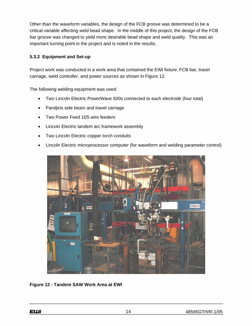
Other than the waveform variables, the design of the FCB groove was determined to be a critical variable affecting weld bead shape. In the middle of this project, the design of the FCB bar groove was changed to yield more desirable bead shape and weld quality. This was an important turning point in the project and is noted in the results. 5.3.2 Equipment and Set-up Project work was conducted in a work area that contained the EWI fixture, FCB bar, travel carriage, weld controller, and power sources as shown in Figure 12. The following welding equipment was used:
• Two Lincoln Electric PowerWave 500s connected to each electrode (four total)
• Pandjiris side beam and travel carriage
• Two Power Feed 10S wire feeders
• Lincoln Electric tandem arc framework assembly
• Two Lincoln Electric copper torch conduits
• Lincoln Electric microprocessor computer (for waveform and welding parameter control)
Figure 12 - Tandem SAW Work Area at EWI

48565GTH/R-1/05 15
For each electrode, two power sources were connected in a parallel configuration to provide the necessary current required by the process. (Note: The two power supply configuration has been replaced by one dedicated power source by Lincoln Electric on current and future models.) Since two electrodes were used, a total of four PowerWave 500s were employed. A microprocessor computer (controller) was used to control welding parameters such as voltage and current, as well as many additional waveform variables. Wire feed speed was determined by the controller. Since electrode melting rate was set by the waveform variables entered, the control adjusted wire feed speed during the process to maintain the set voltage. Most welds were performed using a square waveform shape rather than a sine wave. Principle waveform variables are.
• Balance: This represents the time spent by the current in positive and negative polarities. For example, a 60/40 balance would mean that the electrode current experienced positive polarity 60% of the time and negative polarity 40% of the time.
• RMS Current: This is the root mean square value of the current delivered to the electrode. The RMS current is used in calculating the heat input for the tandem SAW process.
• Phase Angle: The phase angle refers to the temporal spacing of the current waveforms of the two electrodes. It is important that the phase angle not allow the two waveforms to be in-phase with each other. Careful setting of the phase angle helps minimize arc interaction effects that could be detrimental to the weld.
• Frequency: The number of complete cycles of the AC waveform in one second of time. Frequency is measured in Hertz (Hz). The frequency is usually adjusted to achieve arc stability. Changing the balance to certain settings will often require a change in frequency.
• DC Offset: This is the amount that the waveform current levels are shifted +/-. With a DC-AC configuration on the lead and trail arcs respectively, DC Offset will affect the bead width.
Figure 13 illustrates some of these concepts on a Current vs. Time plot.

48565GTH/R-1/05 16
Figure 13 - Waveform Variables Used in Tandem SAW Development The tandem SAW framework assembly was used to position the copper torch conduits in-line and accurately spaced with the correct angles. The lead copper conduit was positioned vertically straight (0° work and travel angle) and the trail copper conduit was positioned with a specified push travel angle and 0° work angle. Electrode spacing was measured by inching the wires out to the plate surface and measuring the center-to-center distance between them. 5.3.3 Materials The materials used in this project consisted of the base plates, electrode, and flux. Each weld plate consisted of two 6-in. wide by 24-in. long steel plates tacked together using run-on and run-off tabs. All welds were made on square butt joints with varying root openings. The sides of the plates were milled flat and primer was ground off the top and bottom surfaces around the joint. The following plate thicknesses and material types were used:
• 5-mm plate, DH-36 steel
• 8-mm plate, DH-36 steel
• 10-mm plate, EH-36 steel

48565GTH/R-1/05 17
The following welding consumables were used:
• Lincoln Electric L-61 electrode (AWS designation EM12K)
• 761 flux (AWS designation F7A2)
Depending on the FCB groove design used, different electrode diameters were used. Welds made with the original FCB groove design used a 3/16-in. diameter lead electrode and a 1/8-in. diameter trail electrode. Welds made with the improved FCB groove design used a 5/32-in. diameter lead and a 3/32-in. diameter trail electrode. 5.3.4 Original FCB Groove Design Procedure Development and Results All welds in this section were made using the original FCB groove design with the dimensions shown in Figure 4. The square groove in the copper bar was filled with flux up to a nominal 3-mm height above the bar surface. Plates were then laid into the fixture with the root opening compressed on the flux bed. Electrode sizes were 3/16-in. diameter and 1/8-in. diameter for the lead and trail, respectively. Run-on and run-off tabs were used for most welds. The on/off tabs were welded to the ends of the plate and used to help maintain the gap during welding. If no run-on or run-off tabs were used, then tack welds were made at the ends and middle of the joint to help maintain root openings. Initial welding trials for each plate thickness used a 50-50 balance AC waveform on both lead and trail electrodes (AC-AC) as a starting point. Initial contact tip-to-work distance, electrode spacing, trail electrode travel angle, and root opening values were based closely on recommendations in the 13th edition of The Procedure Handbook of Arc Welding published by Lincoln Electric. These values were changed during welding in order to improve arc stability and weld bead quality. Appendix A lists the parameters used for all butt welds made with the original FCB groove design. Unless otherwise noted, the waveform frequency was 80 Hz and the phase angle between the two electrode waveforms was 90° out-of-phase. In some trials for the 5-mm plate, the lead electrode was switched to 1/8-in. diameter (the same as the trail). For each material thickness, Table 4 contains the range of root openings, travel speeds, and RMS currents tested at the 50-50 balance for each electrode using the tandem SAW process.

48565GTH/R-1/05 18
Table 4 - Root Openings, Travel Speeds, and RMS Current Ranges Evaluated
RMS Current Range Plate
Thickness (mm)
Root Opening Range (mm)
Travel Speed Range (ipm)
Lead (amps)
Trail (amps)
5 0.0 - 4.0 30 - 65 350 - 750 300 - 500 8 3.0 - 6.2 35 - 50 650 - 900 500 - 700
10 4.0 - 5.0 30 - 40 700 - 950 500 - 650 Almost all welds suffered from some type of defect or inconsistency with the root bead. The most common defect was root bead suck-back. A macrograph with typical suck-back is shown in Figure 14. Several steps were attempted to overcome the suck-back defect. Increasing or decreasing RMS current and travel speed, varying the balance, using wider root openings, and even adjusting the electrode spacing and contact tip-to-work distance (CTWD) did not effectively eliminate all occurrences of suck-back.
Figure 14 - Weld with Typical Root Bead Suck-Back Repeatability of the welds was also a problem. When a good weld was obtained, it was very hard to repeat in terms of bead shape and overall quality. Figure 15 shows the root side of two welds each made with the same joint fit-up and welding parameters. W39 had good root bead penetration, but W41 had extreme suck-back along the entire weld length. Inconsistency along the length of the weld was also a factor. Many welds had good start and end bead shapes but exhibited suck-back in the middle portion of the joint.

48565GTH/R-1/05 19
Figure 15 - Inconsistent Suck-Back Defects on Welds Made with Identical Parameters Figure 16 shows three welds that illustrate this problem. The middle portion of each weld has more pronounced suck-back than the ends.
Figure 16 - Welds with Pronounced Suck-Back in the Middle Span Suck-back and repeatability problems may result from the compression of the plates onto the flux backing. The pressure exerted by the flux may force the weld bead to suck-back from the root side. Faster travel speeds and cooling rates may also contribute to this condition. Tests were performed with varying levels of flux height on the FCB. Leaving the flux level flush with the FCB bar surface had the greatest effect on eliminating suck-back. Inconsistency and repeatability problems still occurred, and the root bead was found to over-penetrate with excessive reinforcement in some areas. Based on these observations, the FCB groove design and flux fill procedures were found to play a major role in weld quality.

48565GTH/R-1/05 20
Since suck-back and inconsistency problems with tandem SAW could not be fixed, single electrode SAW was performed to further investigate the phenomena. Welds were performed on 5-mm plate butt joints using parameters listed in Appendix A. Single wire SAW welds did not exhibit the same suck-back or inconsistency problems as those made with the tandem SAW process on the original FCB groove design, perhaps due to the slower travel speeds inherent to the process. The best single wire process parameters were determined as follows:
• Wire Diameter: 3/16-in.
• CTWD: 1.25-in.
• RMS Current: 650 A (square waveform)
• Balance: 50-50 AC
• Voltage: 35 V
• Travel Speed: 32 ipm
• Root Opening: 0-mm (no gap) 5.3.4.1 Analysis of High-Speed Tandem SAW Process with Original FCB Groove With the original FCB groove design and backside flux compression, welds made with the high-speed tandem SAW process exhibited several detrimental problems. Root bead suck-back, poor weld repeatability, and inconsistency along the weld length were issues that frequently occurred. Efforts made to resolve these issues were unsuccessful. The exact cause of these problems is unknown, but is most likely to involve factors such as the FCB groove design, backside flux compression, and the higher travel speeds. Single wire SAW was more successful in achieving better weld quality and bead shape using the original FCB groove design. 5.3.4.2 Consultation with The Lincoln Electric Company After considerable experimentation, a consultation with The Lincoln Electric Company representatives was undertaken to discuss ways to resolve the suck-back and inconsistency problems and to improve the FCB bar groove design. The original FCB bar groove design was made for modified S-SAW welding in which wide root openings and slow travel speeds are commonly used. For the high-speed tandem SAW process, a FCB groove that accommodates the smaller root openings and faster speeds should be used. Lincoln Electric has experienced success with alternate FCB groove designs and proposed two options: one for 5-mm plate and another for 8- and 10-mm plate thicknesses. Figure 17 is an illustration of the 5-mm FCB groove design; Figure 18 is the 8- and 10-mm groove design.

48565GTH/R-1/05 21
Figure 17 - Lincoln Recommended FCB Groove for 5-mm Square Butt Joints
Figure 18 - Lincoln Recommended FCB Groove for 8- and 10-mm Square Butt Joints The design for the 8- and 10-mm plates was selected for use with all plate thicknesses. Lincoln Electric recommended that the flux be filled only to the top of the FCB bar surface (avoiding any compression of flux against the weld root) and recommended changing electrode diameters to a 5/32-in. lead and a 3/32-in. trail. The polarity and balance for the electrodes was also discussed. Lincoln was not sure if an AC-AC waveform would provide enough heat to penetrate through the plates. They suggested that the plate thicknesses, root opening, and joint design may necessitate the use of DC+ polarity on the lead electrode to achieve full penetration. 5.3.5 Improved FCB Groove Design Procedure Development and Results The copper bar used in the previous experiments was turned over and a new groove with the dimensions in Figure 18 was machined. Before welding, the groove was filled with flux and the top surface of the FCB bar was scraped flush. 5/32-in. diameter and 3/32-in. diameter electrodes were used on the lead and trail arcs, respectively. Appendix B contains the welding parameters and joint fit-ups for each weld made with the improved FCB groove design. Square butt joints with variable root openings were used for all welds. Primer was ground off the top and bottom of each plate. Run-on and run-off tabs were used for all welds made with the improved FCB groove design. The sections below provide details on the procedure, welding, distortion, and qualification results for each plate thickness.

48565GTH/R-1/05 22
5.3.5.1 5-mm Procedure Initially single wire DC+ parameters were run in order to obtain an estimate of the amount of current needed to achieve penetration, as well as, to determine a starting point for travel speed. Initial tandem SAW welds with DC+ polarity on the lead electrode and 50-50 AC balance on the trail provided too much penetration on the 5-mm plate. The lead electrode polarity was switched to AC with a 50-50 balance (trail electrode also at 50-50 AC balance) and tests were performed to maximize travel speed with these polarities. Table 5 lists the parameters for the developed AC-AC procedure using 50% electrode positive (EP) on both electrodes (W96). Figure 19 shows the macrograph of weld W96. Penetration was complete, root bead shape was very consistent along the entire weld length, and no suck-back was observed. The root bead also appeared to be a bright silver color compared to the dull gray color of the welds made with the original FCB bar. Subsequent tests were run to repeat the weld, all of which produced similar weld beads, demonstrating a high degree of repeatability for high-speed tandem SAW with the improved FCB bar design. Table 5 - W96 Parameters (5-mm Plate) WELD Plate Root Wire TRAVEL Combined Lead Trail DATAID Thickness Opening Separation SPEED Heat Input WFS WFS ACQ
(mm) (mm) (in.) (ipm) (kJ/inch) (ipm) (ipm) FILENAME
5 1.9 to 2.0 0.78 55 41.9 60 180 _10-21-05_10.06.59.txt
Wire Dia Trav. Angle Tip-to-Work Waveform, RMS Current VOLT(in.) (degr.) (in.) %EP, DCOffst SETPOINT SETPOINT
0.15625 0 1.25CC sq, bal=50%, DCOffs=0 650 33
Wire Dia Trav. Angle Tip-to-Work Waveform, RMS Current VOLT(in.) (degr.) (in.) %EP, DCOffst SETPOINT SETPOINT
0.09375 12 1.250CC sq, bal=50%, DCOffs=0 500 34
W96
-------------------------------LEADING WIRE PARAMETERS--------------------------------
-----------------------------TRAILING WIRE PARAMETERS-----------------------------

48565GTH/R-1/05 23
Figure 19 - Macrograph of Weld on 5-mm Plate (W96) Additional welds were run using a 50-50 AC balance on the lead electrode and a 40-60 (40% EP) AC balance on the trail for added electrode deposition and slightly less root bead reinforcement. While keeping all the aforementioned benefits of the W96 procedure, this procedure allowed better bridging of wider root openings and was selected as the preferred 5-mm procedure; parameters are listed in Table 6 (W108). The macrograph of weld W108 is shown in Figure 20. Table 7 lists the bead measurements. Table 6 - Preferred 5-mm Plate Procedures (W108) WELD Plate Root Wire TRAVEL Combined Lead Trail DATAID Thickness Opening Separation SPEED Heat Input WFS WFS ACQ
(mm) (mm) (in.) (ipm) (kJ/inch) (ipm) (ipm) FILENAME
5 1.9 to 2.0 0.78 55 41.4 60 190 _10-27-05_08.35.19.txt
Wire Dia Trav. Angle Tip-to-Work Waveform, RMS Current VOLT(in.) (degr.) (in.) %EP, DCOffst SETPOINT SETPOINT
0.15625 0 1.25CC sq, bal=50%, DCOffs=-8200 650 33
Wire Dia Trav. Angle Tip-to-Work Waveform, RMS Current VOLT(in.) (degr.) (in.) %EP, DCOffst SETPOINT SETPOINT
0.09375 12 1.250
CC sq, bal(+)=40%, DCOffs=-8200, Phase=105 deg 500 33
W10
8
-------------------------------LEADING WIRE PARAMETERS--------------------------------
-----------------------------TRAILING WIRE PARAMETERS-----------------------------

48565GTH/R-1/05 24
Figure 20 - Weld Made with Preferred 5-mm Plate Procedures (W108) Table 7 - Bead Measurements with Preferred 5-mm Plate Procedures (W108)
W108 Plate Size (mm)
Top Reinforcement
Height (mm)
Bottom Reinforcement
Height (mm)
Total Weld Bead Area
(mm2)
Deposition Area
(mm2)
Top Bead Width (mm)
Root Bead Width (mm)
Base Metal
Dilution %
5 1.31 1.34 77.66 30.853 15.3 11 62.5 Gap Weldability Gap weldability tests were performed by varying the root opening of the butt joint. The nominal gap used for the 5-mm welds was 2.0-mm. Tests were run on 0.0- to 3.0-mm wide root openings with the same welding parameters as in Table 6. The developed 5-mm procedure successfully bridged gaps from 2.0- to 3.0-mm (macro shown in Figure 21). The procedure was able to penetrate down to a gap of 1.4-mm, but the arc became slightly unstable (due to inconsistent wire feed) and the root bead width was small compared to the other welds (macro shown in Figure 22).

48565GTH/R-1/05 25
Figure 21 - Weld with 3.0-mm Root Opening on 5-mm Plate
Figure 22 - Weld with 1.4-mm Root Opening on 5-mm Plate At the request of NGSS, a procedure for a zero gap butt joint was developed for the 5-mm plate. Several current levels and waveform variables were adjusted to attempt a successful tandem SAW weld with no gap. The process was not able to penetrate the plate unless travel speed was slowed considerably or RMS current was increased (both of which increase heat input and distortion potential). When penetration was full and complete, the level of bead quality was not the same as with the AC-AC procedures developed previously with root openings.

48565GTH/R-1/05 26
5.3.5.2 8-mm Procedure DC+ polarity was used on the lead electrode with a 50-50 AC balance on the trail. Initial welds performed with this configuration yielded good results, so work was focused on maximizing travel speed with a DC-AC configuration. With this configuration, the trail electrode polarity balance was always kept at 50% EP and 50% electrode negative (EN). This was done to minimize arc blow effects resulting from different balance amounts. RMS current values and DC offset were varied during the tests. DC offset was typically kept at 0 for most tests. The effect of DC offset on wire feed speed is shown in Figure 23 (wire feed speed (WFS) was measured from the 3/32-in. diameter trail electrode operating at 500 amps RMS current and 50% EP balance (values listed in Appendix C). While lower (less than 0) offset values did not significantly affect the wire feed, higher offset values did. Less deposition was experienced with higher DC offset values, which would necessitate a reduction in travel speed if all other variables are kept the same.
0
20
40
60
80
100
120
140
160
180
200
-40000 -30000 -20000 -10000 0 10000 20000 30000 40000
DC Offset Setting
WFS
(ipm
)
Figure 23 - Effect of DC Offset on Wire Feed Speed of Trail Electrode Table 8 lists the parameters for the preferred 8-mm procedure (W97). Bead shape was very consistent along the weld length and exhibited good root bead penetration with no visible defects or discontinuities. Figure 24 shows a macrograph of the W97 weld. Table 9 lists the bead measurements. This weld was repeated successfully several times.

48565GTH/R-1/05 27
Table 8 - Preferred 8-mm Plate Procedure (W97) WELD Plate Root Wire TRAVEL Combined Lead Trail DATAID Thickness Opening Separation SPEED Heat Input WFS WFS ACQ
(mm) (mm) (in.) (ipm) (kJ/inch) (ipm) (ipm) FILENAME
8 3.4 to 3.3 0.78 35.0 72.9 62 175 _10-21-05_11.01.49.txt
Wire Dia Trav. Angle Tip-to-Work Waveform, RMS Current VOLT(in.) (degr.) (in.) %EP, DCOffst SETPOINT SETPOINT
0.15625 0 1.25 CC DC+ 750 34
Wire Dia Trav. Angle Tip-to-Work Waveform, RMS Current VOLT(in.) (degr.) (in.) %EP, DCOffst SETPOINT SETPOINT
0.09375 12 1.250CC sq, bal=50%, DCOffs=0 500 34
W97
-------------------------------LEADING WIRE PARAMETERS--------------------------------
-----------------------------TRAILING WIRE PARAMETERS-----------------------------
Figure 24 - Weld Made with 8-mm Preferred Procedures (W97) Table 9 - Bead Measurements with Preferred 8-mm Procedures (W97)
W97 Plate Size (mm)
Top Reinforcement
Height (mm)
Bottom Reinforcement
Height (mm)
Total Weld Bead Area
(mm2)
Deposition Area
(mm2)
Top Bead Width (mm)
Root Bead Width (mm)
Base Metal
Dilution %
8 1.34 1.25 137.03 50.53 21.05 11.4 63.1

48565GTH/R-1/05 28
Gap Weldability The preferred 8-mm procedure (W97) incorporated a nominal 3.0-mm root opening. Gap weldability tests were performed by varying the root opening from 1.2-mm to 5.5-mm. Root bead penetration was found to be complete over the entire range of root openings, with the lower end of the range (less than 1.5-mm gap) not demonstrating the same bead shape quality as the rest of the root openings tested. The range of root openings that the 8-mm procedure successfully bridged and produced high quality bead shape in this experiment was between 2.0-mm and 5.0-mm (macros shown in Figure 25 and Figure 26 respectively).
Figure 25 - Weld with 8-mm Procedures and 2.0-mm Root Opening
Figure 26 - Weld with 8-mm Procedure and 5.0-mm Root Opening

48565GTH/R-1/05 29
5.3.5.3 10-mm Procedure Procedure development for the 10-mm plate was similar to that of the 8-mm plate. DC+ polarity was run on the lead electrode using a 50-50 AC balance on the trail. RMS current values, root openings, and DC offset were varied during the experiment to obtain a high travel speed tandem SAW procedure. Table 10 lists the parameters for the preferred 10-mm procedure ( W98). Bead shape was very consistent along the entire weld length and exhibited good root bead penetration with no visible defects or discontinuities. Figure 27 shows a macrograph of the W98 weld. Table 11 lists the bead measurements. This weld was repeated successfully several times. Table 10 - Preferred 10-mm Plate Procedure (W98) WELD Plate Root Wire TRAVEL Combined Lead Trail DATAID Thickness Opening Separation SPEED Heat Input WFS WFS ACQ
(mm) (mm) (in.) (ipm) (kJ/inch) (ipm) (ipm) FILENAME
10 3.8 to 4.0 0.78 30.0 88.4 70 175 _10-21-05_13.03.36.txt
Wire Dia Trav. Angle Tip-to-Work Waveform, RMS Current VOLT(in.) (degr.) (in.) %EP, DCOffst SETPOINT SETPOINT
0.15625 0 1.25 CC DC+ 800 34
Wire Dia Trav. Angle Tip-to-Work Waveform, RMS Current VOLT(in.) (degr.) (in.) %EP, DCOffst SETPOINT SETPOINT
0.09375 12 1.250CC sq, bal=50%, DCOffs=0 500 34
W98
-------------------------------LEADING WIRE PARAMETERS--------------------------------
-----------------------------TRAILING WIRE PARAMETERS-----------------------------
Figure 27 - Weld Made with 10-mm Preferred Procedure (W98)
W98

48565GTH/R-1/05 30
Table 11 - Bead Measurements with Preferred 10-mm Procedures (W98)
W98 Plate Size (mm)
Top Reinforcemen
t Height (mm)
Bottom Reinforcemen
t Height (mm)
Total Weld Bead Area
(mm2)
Deposition Area
(mm2)
Top Bead Widt
h (mm)
Root Bead Width (mm)
Base Metal
Dilution %
10 1.76 0.834 181 67.77 21.45 14.45 62.5 In addition, several tests were performed to develop a set of AC-AC parameters for the 10-mm plate (see tests W94, W95, and W103 in Appendix B). Parameters were obtained that produced acceptable welds in terms of bead shape and quality, but not as good as the quality level of the DC-AC welds. In addition, the AC-AC parameters did not provide a significant reduction in heat input compared to the DC-AC parameters. For that reason, the DC-AC parameters were selected for the preferred 10-mm procedure. Gap Weldability The preferred 10-mm procedure (W98) incorporated a nominal 4.0-mm root opening. Gap weldability tests were performed by varying the root opening from 1.5-mm to 6.0-mm. Root bead penetration was found to be complete over the entire range of root openings, with the lower end of the range (less than 2.2-mm gap) not having the same bead shape quality as the rest of the root openings tested. The range of root openings that the 10-mm procedure successfully bridged and produced high quality bead shape in this experiment was between 3.0-mm and 5.5-mm. Macros of a 3.0-mm root opening and a 6.0-mm root opening are shown in Figure 28 and Figure 29 respectively. A root opening of 6.0-mm resulted in some undercut on the root bead side, likely resulting from lack of fill. Root openings less than 3.0-mm still produced high quality welds, but the level of repeatability was not as high as with larger root openings.

48565GTH/R-1/05 31
Figure 28 - Weld with 10-mm Procedure and 3.0-mm Root Opening
Figure 29 - Weld with 10-mm Procedure and 6.0-mm Root Opening 5.3.5.4 Distortion Measurements Before and after distortion measurements were taken on plates W96, W97, and W98. A ROMER arm (Figure 30) was used to measure the out-of-plane distortion (z coordinate) from a selected reference point on the plate.

48565GTH/R-1/05 32
Figure 30 - ROMER Arm Coordinate Measuring System

48565GTH/R-1/05 33
Figure 31 shows a layout of the weld plate and the location of the distortion points measured (32 total points). Point 1 is the reference point.
Figure 31 - Distortion Measurement Locations The W96 test weld represents the worst case distortion of all 5-mm plates welded using both the W96 procedures and the preferred W108 procedures. Figure 32 shows a three-dimensional graph of the distortion for the 5-mm weld W96. Before weld distortion measurements are listed in Appendix D; after weld values are in Appendix E. Reference point 1 corresponds to the 0, 0, 0 location on the graph. The maximum out-of-plane distortion measured was in the middle of the plate where it bowed approximately 0.4-in. (10-mm) above the original location. However, even when welded using the same procedures, the 5-mm plates did not always exhibit the same degree of distortion. Most plates had flexible buckling, in which the plate could be flexed in two positions, rather than being locked into one stiff position.
Y
X

48565GTH/R-1/05 34
- 0 .2
0 .0
0 .2
0 .4
0 .6
0 .8
1 .0
- 5 0 5 1 0 1 5 2 0 2 5
- 1 2- 1 0
- 8- 6- 4- 20
Z D
ata
(inch
es)
X D a ta ( in c h e s )
Y Da ta (inches)
5 m m p la te d is to r t io n ( W 9 6 )
B e fo r e W e ld in gA f te r W e ld in g
Figure 32 - 3-D Graph of Distortion Before and After Weld (5-mm Plate W96) The W97 and W98 welds were made using the preferred 8- and 10-mm procedures and root openings. These plates did not exhibit much out-of-plane distortion. Figure 33 shows the three-dimensional graphs of the distortion for the 8-mm plate (W97). Before weld distortion measurements are listed in Appendix F; after weld values are in Appendix G. Figure 34 show three-dimensional graphs of the distortion for the 10-mm plate (W98). Before weld values are listed in Appendix H; after weld values are in Appendix I.

48565GTH/R-1/05 35
- 0 . 2
0 . 0
0 . 2
0 . 4
0 . 6
0 . 8
1 . 0
- 5 0 5 1 0 1 5 2 0 2 5- 1 2
- 1 0- 8- 6- 4- 20
Z D
ata
(inch
es)
X D a t a ( i n c h e s )
Y D a ta ( in c h e s )
8 m m p l a t e ( W 9 7 )
B e f o r e P l a t eA f t e r P l a t e
Figure 33 - 3-D Graph of Distortion Before and After Weld (8-mm Plate W97)
- 0 . 2
0 . 0
0 . 2
0 . 4
0 . 6
0 . 8
1 . 0
- 5 0 5 1 0 1 5 2 0 2 5- 1 2
- 1 0- 8- 6- 4- 20
Z D
ata
(inch
es)
X D a t a ( i n c h e s )
Y D a ta ( in c h e s )
1 0 m m p l a t e D i s t o r t i o n
B e f o r e W e l d i n gA f t e r W e l d i n g
Figure 34 - 3-D Graph of Distortion Before and After Weld (10-mm Plate W98)

48565GTH/R-1/05 36
Transverse shrinkage measurements were made by measuring eight end locations along the length of the plate (shown in Figure 31 as points T1 through T8). Since the plate sizes were small and the clamps were not hydraulic (supplied less hold down force), the plates had a tendency to pull towards the center of the weld. This may have affected the root opening of the joint, meaning that the root opening measured before welding may not have been exactly the same once the arc passed over that location. Figure 35 shows a graph of the transverse shrinkage experienced for each plate thickness. The effect of root opening on transverse shrinkage was also assessed in Figure 36 (8-mm plate thickness used). These graphs show that the worst shrinkage is experienced that in the middle of the joint. In the middle of the weld, the 5-mm plate pulled in toward the weld approximately 1-mm and the 8- and 10-mm plates pulled in approximately 1.4-mm. Varying root openings did not significantly affect the amount of transverse shrinkage.
SHRINKAGE OF 5, 8, 10 mm PLATES
0
10
20
30
40
50
60
1 2 3 4 5 6 7 8POSITION
1/10
00's
INCH 8 mm plate, 3 mm gap5 mm plate, 2mm gap10 mm plate, 4 mm gap
Figure 35 - Transverse Shrinkage of Preferred Procedure Welds
SHRINKAGE OF 8 mm PLATES
0
10
20
30
40
50
60
1 2 3 4 5 6 7 8POSITION
1/10
00's
INC
H
8 mm plate, 3 mm gap8 mm plate, 2 mm gap8 mm plate, 5 mm gap
Figure 36 - Effect of Root Opening on Transverse Shrinkage

48565GTH/R-1/05 37
5.3.5.5 Procedure Qualification 5-mm Procedure The weld made using the preferred 5-mm procedures (W108) was subjected to visual and nondestructive evaluation (NDE) standards. The weld was found to pass Class 1 visual observation criteria as given in MIL-STD-2035A. NDE using radiography and magnetic particle testing was performed in accordance with NAVSEA technical publication 89074-AQ-GIB-010/248. No defects or discontinuities were found and the weld was acceptable under Class 1 MIL-STD-2035A radiograph and magnetic particle standards. Appendix J contains the welding parameter data and the lead/trail electrode Current waveforms captured with high speed data acquisition equipment during the execution of this weld. 8-mm Procedure The weld made using the preferred 8mm procedures (W97) was subjected to visual and NDE standards. The weld was also found to pass Class 1 visual observation criteria as given in MIL-STD-2035A. NDE using radiographs and magnetic particle testing was performed in accordance with NAVSEA technical publication S9074-AQ-GIB-010/248. No defects or discontinuities were found and the weld was acceptable under Class 1 MIL-STD-2035A radiograph and magnetic particle standards. Appendix K contains the welding parameter data and the lead/trail electrode Current waveforms captured with high speed data acquisition equipment during the execution of this weld. 10-mm Procedure The weld made using the preferred 10-mm procedures (W97) was subjected to visual and NDE standards. The weld was found to pass Class 1 visual observation criteria as given in MIL-STD-2035A. NDE using radiographs and magnetic particle testing was performed in accordance with NAVSEA technical publication 89074-AQ-GIB-010/248. No defects or discontinuities were found and the weld was acceptable under Class 1 MIL-STD-2035A radiograph and magnetic particle standards. Appendix L contains the welding parameter data and the lead/trail electrode current waveforms captured with high speed data acquisition equipment during the execution of this weld. The 10-mm plate was selected for mechanical testing to NAVSEA technical publication S9074-AQ-GIB-010/248. Mechanical tests results are presented in Table 12. Transverse tensile tests and root and face bends were performed in accordance to AWS B4.0 standards. Although not required on this thickness, charpy impact tests were performed in the base material, heat-affected zone (HAZ), and weld metal (also in accordance to AWS B4.0). These charpy specimens were sub-sized. A conversion to full sized specimen impact energy is given in Table 13. All tests results passed acceptance criteria as given by the filler metal standard MIL-E-23765/4, which required a minimum tensile elongation of 22%, a minimum 20 ft-lbs impact strength at -20°F, and no visible defects on the bend specimens.

48565GTH/R-1/05 38
Table 12 - Mechanical Test Results for Preferred 10-mm Plate Weld – Actual Values
Lab Services
WELD QUALIFICATION TEST RECORD-AMENDEDAmended: To correct charpy notch location
Project No.: Weld No.: Job No.: Customer:
Technician: Test Date: Test Frame: Loading Rate: 0.05 (in/min) 1.27 (mm/min)Orientation: Test Temperature: Room Temperature
Failure Location
Base MetalBase Metal
Technician: Test Date: Test Frame: Notch Orientation:
Technician: Test Date:
Test Conducted By: Reviewed by:Title: Senior Technician Title: Senior Engineer
Date Amended:
This report is the confidential property of our client and may not be used for advertising purposes.
100273.9 202 2.30 90.611 Base Metal -29 -20
CHARPY IMPACT ENERGY TEST RECORD - ASTM E23
BEND TEST RECORD - ASTM E190
1250 Arthur E. Adams Drive Columbus, OH 43221
CROSS WELD TENSION TEST RESULTS - ASTM E8
65.4
T-L per AWS B4.0
Elongation %RA(%) (%)
T-2 1.499 0.384 79.31.503 77.50.389
Ultimate Strength
1 -29WCL2 -29
IDNotch
Location (oF)Spec. Test Temperature
(oC)
T-1
Absorbed Energy(J)
534.5 451.0546.9 62.7 432.4
W-98
Kristen Merlo
2006-98873 Brian Baughman
November 3, 2005
48565 GDE-03
November 3, 2005Kristen Merlo
H1938 UK18Cross Weld
40.7-20(mm)
30(ft-lbs)
40.2
Shear(%)60
Lateral Expansion(mils)
1.020.91 35.8 60
3 -29 -20WCL 36 0.96 37.8 614 -29 -20WCL 27.5 0.84 33.1 56
48.8
31.9 515 -29 -20 37.3WCL 27.5 0.81
7 -29 -20 238.6HAZ2.37 93.3 100
8 -29 -20 303.7HAZ176 1.86
10073.2 100
224 2.06 81.1
(ksi)0.2% Yield StrengthThickness
(ksi) (MPa)(in.) (MPa)IDSpec. Width
(in.)
HAZ 170
-20 40.7WCL 30
37.3
6
Kristen Merlo
-20
151297
-29 230.5
November 3, 2005
Mandrel Diameter(in.) ResultsSpec.
IDThickness
(in.)FB-1FB-2 0.378
0.378Face 1.5
No Visual Defects
Validity
FaceNo Visual Defects Pass
1.5 Pass
Orientation
No Visual Defects PassNo Visual Defects Pass
RB-1 0.375RB-2 0.378 Root 1.5
Root 1.5
29.4 66.627.6 63.0
9 Base Metal -29 -20100
279.3 206 2.26 89.0
December 5, 2005
10010 Base Metal -29 -20 279.3 206 2.26 89.0

48565GTH/R-1/05 39
Table 13 below gives the converted values of the charpy impact energies. Equation F.20 from API Recommended Practice 579, Appendix F was used to correlate the sub-size absorbed energy to a calculated full size absorbed energy. The sub-size absorbed energy was multiplied by the ratio of the full size thickness over the sub-size thickness [i.e., 32 ft-lbs x (10-mm/7.47-mm)]. Table 13 – Converted Charpy Impact Absorbed Energies – Full Size Conversion
11 Base Metal -29 -20 365.2 269.3373.4 275.410 Base Metal -29 -20
9 Base Metal -29 -20 372.9 275.0405.5 299.18 HAZ -29 -20
7 HAZ -29 -20 318.2 234.7308.6 227.66 HAZ -29 -20
5 WCL -29 -20 49.8 36.749.4 36.54 WCL -29 -20
3 WCL -29 -20 64.4 47.554.5 40.2
-29 -202 WCL -29 -20
54.5 40.2ID Location (oC) (oF) (J) (ft-lbs)1 WCL
Spec. Notch Test Temperature Absorbed Energy
CHARPY IMPACT ENERGY TEST RECORD - ASTM E23Full size correlation from subsize samples
API recommended practice, Eqn. F.20
5.3.5.6 Thick Section Welding with 8-mm Procedures Although not part of the project plan, at the request of Paul Hebert of NGNN (the NSRP Program Technical Representative (PTR)), EWI attempted to weld 1-in. thick steel plates using the developed tandem SAW procedures. A butt joint configuration with each plate having a 45° bevel and a 5.5-mm root face was used. The root opening between the two plates was 3.0-mm. The preferred procedure developed for the 8-mm plate thickness was used. The bead profile was very nice, with complete penetration, good wetting into the joint, and consistent root bead reinforcement height. Future 1-in. thick butt joints may benefit from a reduced bevel angle. Welding parameters and a photo macrograph are presented in Appendix M. 5.3.5.7 Analysis of High-Speed Tandem SAW with Improved FCB Groove The improved FCB groove design allowed for successful high-speed NG tandem SAW FCB. Welds exhibited high quality bead shape, repeatability, and consistency along the weld length. Welds made using the preferred procedures for each plate thickness were found to meet visual, NDE, and mechanical property criteria of all relevant codes and standards.

48565GTH/R-1/05 40
Distortion of the plates was minimal. The maximum distortion measured on the 5-mm plate was 0.4-in. of bowing distortion and 1-mm of transverse shrinkage. Most 5-mm plates exhibited flexible buckling. The maximum bowing distortion measured for the 8- and 10-mm plates was 0.05-in. and 0.03-in. respectively. The maximum transverse shrinkage for both plate thicknesses was 1.4-mm. Comparison to the modified S-SAW process reveals the benefits of the high-speed tandem SAW process. The following tables (Table 14 and Table 15) compare known process parameters and bead shape measurements. (Note: Distortion measurements are not compared since different plate sizes and fixtures were used for both processes. Mechanical test results for the modified S-SAW welds were not available.) Travel speeds for the tandem SAW process were more than twice as fast as the S-SAW process. Calculated heat input of tandem SAW was 2/3 less than that of the modified S-SAW process (note: heat input measured with thermal couples may differ significantly from the calculated). Tandem SAW improved bead shape and eliminated excessive reinforcement on both faces of the joint. Deposition area was reduced approximately 50% for each plate thickness with the tandem SAW process. Base metal dilution percentage increased approximately 20% with the tandem SAW process. Bead widths on the top and root sides did not vary significantly between processes.

48565GTH/R-1/05 41
Table 14 - Modified S-SAW vs. Tandem SAW Welding Parameter Comparison
Plate Thickness Root Opening Travel Speed Heat Input (mm) Lead Trail (mm) (ipm) (kJ/in)
5 3/16 1/8 4.0 20 60.308 3/16 1/8 4 to 5 16 97.88
10 3/16 1/8 5 to 6 14 123.43
Plate Thickness Root Opening Travel Speed Heat Input (mm) (mm) (ipm) (kJ/in)
Lead Trail Lead Trail Lead Trail Lead Trail5 5/32 3/32 2.0 650 - 50% EP 500 - 40% EP 33 33 60 190 55 41.408 5/32 3/32 3.0 750 - DC+ 500- 50% EP 34 34 62 175 35 72.90
10 5/32 3/32 4.0 800 - DC+ 500- 50% EP 34 34 70 175 30 88.40
WFS(ipm)
WFS
485460
-----------------------------------------------------------------------------------------------------------SERIES ARC-----------------------------------------------------------------------------------
----------------------------------------------------------------------------------------------------------TANDEM SAW----------------------------------------------------------------------------------
(in.)
725800
(ipm)
RMS Current(A)
Voltage(V)
36
(V)
Electrode Dia.
Electrode Dia. (in)
600(A)
Current Voltage
33.536
Table 15 - Modified S-SAW vs. Tandem SAW Bead Shape Dimension Comparison
Plate Top Bottom Total Weld Deposition Top Bead Root Bead Base Metal Size Reinforcement Reinforcement Bead Area Area (mm2) Width (mm) Width (mm) Dilution %(mm) Height (mm) Height (mm) (mm2)
5 3.83 -0.236 98.8 64.258 16.04 9.5 34.968 3.6 1.5 188.12 105.859 21.12 14.5 43.7310 3.04 2.36 204.96 117.9 20.18 13.93 42.48
Plate Top Bottom Total Weld Deposition Top Bead Root Bead Base Metal Size Reinforcement Reinforcement Bead Area Area (mm2) Width (mm) Width (mm) Dilution %(mm) Height (mm) Height (mm) (mm2)
5 1.31 1.34 77.66 30.853 15.3 11 62.568 1.34 1.25 137.03 50.53 21.05 11.4 63.1210 1.76 0.834 181 67.77 21.45 14.45 62.56
.-----------------------------------------------TANDEM SAW-------------------------------------------------
----------------------------------------------------------------SERIES ARC--------------------------------------------------------------------

48565GTH/R-1/05 42
5.4 Process Demonstration On November 22, 2005, a process demonstration was held at EWI for team members and the NSRP PTR. Participants included Lee Kvidahl (NGSS - Pascagoula), Nick Evans (NGSS - New Orleans), Harry Sadler (Lincoln Electric Company), and Jon Sweeny (NGNN) representing Paul Hebert (the NSRP PTR). The agenda consisted of a presentation of project results (Appendix N) followed by a successful demonstration of high-speed NG tandem SAW of each plate thickness using the preferred procedures developed by this project. Figure 37 through Figure 39 are pictures taken during the welding demonstrations.
Figure 37 - Loading Flux into the Improved FCB Before Welding

48565GTH/R-1/05 43
Figure 38 - High Speed Data Acquisition During Weld
Figure 39 - Representatives from NGSS and NGNN Examine Plates After Welding

48565GTH/R-1/05 44
5.5 Financial Considerations Narrow groove (NG) butt joint welding technology is required to make complex panels with multiple thickness transitions, cut-outs, and inserts without distortion. This welding technology is feasible for NGSS since the new panel line is being purchased with a plate mill that can assure joint gap and profile accuracy. Even without the precision of a plate mill, the wide ranging gap tolerance of the developed tandem SAW procedures may allow high quality welds with the current oxyfuel and plasma arc plate cutting systems. The results can also be deployed at shipyards that use tandem SAW welding with FCB that need to build thin steel panels. NGSS believes that the combination of machined weld preparations, rigid clamping (provided by the FRO machine), and NG high-speed SAW FCB offer the ability to minimize heat input and distortion with the least amount of capital investment. A brief cost analysis was performed comparing the modified S-SAW process to the tandem SAW process; Table 16 is a summary of these results. Variables evaluated were the savings in weld metal, process times, and FCB flux layering times (the time it took to build up the flux in the FCB groove). Set-up times and post-weld repair costs were not used since they were not known for the modified S-SAW process. Table 16 - Modified S-SAW vs. Tandem SAW Cost Comparison
Plate Size Total Costand Process Time Labor Rate Metal Cost Speed Labor ($/ft)
(min./ft) ($/hr) (lbs/ft.) ($/lb) (min/ft.) ($/hr)5mm - Series 0.5 55 0.3345 1.75 0.57 55 1.57
5mm - Tandem 0.25 55 0.1606 1.75 0.22 55 0.718mm - Series 0.5 55 0.5511 1.75 0.75 55 2.11
8mm - Tandem 0.25 55 0.2631 1.75 0.34 55 1.0010mm - Series 0.5 55 0.6138 1.75 0.86 55 2.32
10mm - Tandem 0.25 55 0.3528 1.75 0.40 55 1.21
Flux Fill Cost Electrode Cost Process Cost
The flux fill time was measured by recording how much time is required to fill the FCB groove with flux. Since the tandem welds incorporated the new FCB groove, the time was much less since no layering of the flux above the bar surface was necessary. The electrode amount used was calculated by measuring the deposition area and multiplying by a foot length and by the density of steel. Based on the fact that the tandem SAW process is twice as fast as the modified S-SAW process, the tandem SAW process will produce welds in 50% less time. Given the fact that tandem SAW requires very little set-up time and no post-weld repair, the cost savings will be greater if modified S-SAW set-up time and post-weld repair costs are factored in.

48565GTH/R-1/05 45
6.0 Conclusions High-speed narrow-groove (NG) butt joints on 5-, 8-, and 10-mm plate thicknesses were successfully welded using the tandem SAW process. Preferred parameters were selected for each plate based on travel speeds, arc stability, weld bead shape, and weld quality. Each weld made using the preferred parameters passed MIL-STD-2035A criteria for visual, radiography, and magnetic particle examination. The 10-mm butt joint was subjected to mechanical testing per NAVSEA technical publication S9074-AQ-GIB-010/248 and passed all required tests for procedure qualification. The design of the FCB groove was found to have a significant effect on the quality of the tandem SAW process and weld bead shape. A change from the original FCB groove (square shape, 3.5-mm deep by 35-mm wide) used with the current modified S-SAW production process to an improved FCB groove (parabolic shape, 0.09-in. deep by 0.75-in. wide) substantially improved bead shape and arc stability. In addition, the flux fill procedure for the FCB was also found to be significant. Instead of a 3-mm flux height buildup above the FCB bar surface, the flux in the FCB groove need only be filled to the top of the bar surface. The ability to use precision AC-AC and DC-AC waveforms for procedure development was a definite advantage in developing the preferred procedures. Adjustment of the waveform parameters allowed creation of robust procedures with a degree of gap tolerance. The 5-mm plate procedure had approximately 1-mm root opening tolerance while the 8- and 10-mm plate procedures had approximately 3-mm tolerance. It is anticipated that gap tolerance could be increased for the 5-mm plate by refining the procedure to increase the weld metal fill volume. Distortion was found to be minimal for each plate welded with the preferred procedures. The most pronounced distortion measured was on the thinnest plate (5-mm), where out-of-plane distortion was measured at 10-mm. Transverse shrinkage of the plates was minimal, with the most measured being 1.4-mm at the middle of the weld length for the 8- and 10-mm plates. The high-speed NG tandem SAW process was found to offer several benefits over the modified S-SAW process: higher travel speeds (more than twice the speed), less deposited filler metal, improved bead shape, reduced set-up times, and improved quality with reduced post-weld repair. A cursory cost analysis (including FCB flux fill time, process labor time, and filler metal costs) revealed that the tandem SAW process can reduce welding cost per foot by approximately 50% as compared with the current modified S-SAW process. Additional savings could be realized by factoring in reduced weld repair and distortion re-work costs.

48565GTH/R-1/05 46
7.0 Recommendations The high-speed NG tandem SAW FCB process should be considered for implementation at NGSS for thin panel butt welding. Additional procedure refinement is recommended to further increase the tolerance of the procedures to joint fit-up variation. Refined procedures may allow the process to be deployed without milling the plate edges, which would increase the range of deployment opportunities. Once procedures are refined, additional mechanical testing should be performed to qualify the range of material thicknesses. A study evaluating the performance of the developed NG-SAW procedures in a production environment and on full-size panels is also recommended as a precursor to full implementation. This would include characterizing the fit-up requirements and the resultant distortion and weld quality improvements when welding production panels. Finally, welding procedures should be developed for other base materials (e.g., HSLA-65) which are more applicable to other weapon systems like the CVN-21.

48565GTH/R-1/05 47
8.0 References The Lincoln Electric Company, The Procedure Handbook of Arc Welding 13th Edition
(Cleveland: The Lincoln Electric Company. 1994). Naval Sea System Command (NAVSEA) Ship Systems, Welding and Brazing Procedure and
Performance Qualification Technical Publication S9074-AQ-GIB-010/248 (Washington: NAVSEA Ship Systems. 1997).
Naval Sea System Command (NAVSEA) Ship Systems, Nondestructive Testing Acceptance
Criteria MIL-STD-2035A (Washington: NAVSEA Ship Systems. 1995). Naval Sea System Command (NAVSEA) Ship Systems, Electrodes - Welding, Bare, Solid; and
Fluxes, Submerged Arc Welding, Carbon and Low Alloy Steels MIL-E_23765/4 (Washington: NAVSEA Ship Systems. 1989).
American Welding Society, Standard Methods for Mechanical Testing of Welds (U.S.
Customary Units) ANSI/AWS B4.0 (LeJeune: American Welding Society. 1997). American Welding Society, Standard Welding Terms and Definitions AWS A3.0 (LeJeune:
American Welding Society. 2001). American Petroleum Institute, API Recommended Practice 679, Appendix F, Equation F.20
(Washington: American Petroleum Institute, 2000).

48565GTH/R-1/05 48
9.0 Acronyms
Acronym Definition AC Alternating Current
CTWD Contact Tip-to-Work Distance DC Direct Current EN Electrode Negative EP Electrode Positive
EWI Edison Welding Institute FCB Flux Copper Backing ipm Inches per Minute NG Narrow Groove
NGNN Northrop Grumman Newport News NGSS Northrop Grumman Ship Systems NJC Navy Joining Center RMS Root Mean Square SAW Submerged Arc Welding
S-SAW Series Arc Submerged Arc Welding WFS Wire Feed Speed

49 48565GTH/R-1/05
Appendix A – Original FCB Groove Design Welding Parameters
-------------------------------LEADING WIRE PARAMETERS-------------------------------- -----------------------------TRAILING WIRE PARAMETERS----------------------------- WELD
ID Date
Nominal Plate
Thickness (mm)
Gap (mm)
Wire Separation
(in.) Wire Diameter
(in.)
Travel Angle (deg.)
Tip -to-
Work (in.)
Waveform, %EP,
DCOffst
AMP or WFS
SETPOINT
VOLT SETPOINT
Wire Dia (in.)
Travel Angle (deg.)
Tip -to-
Work (in.)
Waveform, %EP,
DCOffst
AMP or WFS
SETPOINT
VOLT SETPOINT
TRAVEL SPEED (ipm)
DATA ACQ
FILENAME COMMENTS
Combined Heat Input
(kJ/inch)
WFS (lead)
WFS (trail) %over
Combined Deposit
Area (in2)
W1 4/26/05 5 1.5 0.56 0.125 0 1.25 CC sq,
bal=50%, DCOffs=0
350 30 0.125 9.5 1.250
CC sq, bal=50%, DCOffs=0
320 29.5 45.5 _04-26-05_13.46.13.txt 26.3
W2 4/26/05 5 1.2 0.56 0.125 0 1.25 CC sq,
bal=50%, DCOffs=0
350 30 0.125 9.5 1.250
CC sq, bal=50%, DCOffs=0
320 29.5 55 _04-26-05_13.55.22.txt 21.8
W3 4/26/05 5 1.5 0.56 0.125 0 1.25 CC sq,
bal=50%, DCOffs=0
450 30.5 0.125 9.5 1.250
CC sq, bal=50%, DCOffs=0
320 29.5 45.5 _04-26-05_14.21.43.txt 30.5
W4 4/26/05 5 1.0 to 1.2 0.56 0.125 0 1.25
CC sq, bal=50%, DCOffs=0
500 31 0.125 9.5 1.250
CC sq, bal=50%, DCOffs=0
350 30 45.5 _04-26-05_14.30.27.txt 34.3 75 50 0.0337
W5 4/26/05 5 3.2 0.56 0.125 0 1.25 CC sq,
bal=50%, DCOffs=0
500 31 0.125 9.5 1.250
CC sq, bal=50%, DCOffs=0
350 30 45.5 _04-26-05_14.53.33.txt 34.3
W6 4/26/05 5 2.5 to 3 0.56 0.125 0 1.25
CC sq, bal=50%, DCOffs=0
450 30.5 0.125 9.5 1.250
CC sq, bal=50%, DCOffs=0
350 30 45.5 _04-26-05_14.59.51.txt 31.9
W7 4/26/05 5 2.5 0.56 0.125 0 1.25
CC sq, bal=50%, DCOffs=2
5K
450 31 0.125 9.5 1.250
CC sq, bal=50%,
DCOffs=-25K 350 31 30 _04-26-05_16.47.04.txt 49.6
W8 4/26/05 5 2.0 to 2.5 0.56 0.125 0 1.25
CC sq, bal=50%, DCOffs=2
5K
400 31 0.125 9.5 1.250
CC sq, bal=50%,
DCOffs=-25K 300 30 30 _04-26-05_17.08.43.txt 42.8
W09 5/19/05 10 4.1 0.45 0.1875 0 1.75 CC sq,
bal=50%, DCOffs=0
800 33 0.125 9.5 1.875
CC sq, bal=50%, DCOffs=0
500 31 30 _05-19-05_16.19.58.txt 83.8
W10 5/19/05 10 4.1 to 5.0 0.45 0.1875 0 1.75
CC sq, bal=50%, DCOffs=0
900 34 0.125 9.5 1.875
CC sq, bal=50%, DCOffs=0
600 32 40 _05-19-05_17.29.07.txt 74.7
Does compressing the flux underneath make any difference? (W09 & W10 were compressed) Try W11 not compressing. Just flux flush with top of copper.
W11 5/20/05 10 4.1 0.45 0.1875 0 1.75 CC sq,
bal=50%, DCOffs=0
900 34 0.125 9.5 1.875
CC sq, bal=50%, DCOffs=0
600 32 40 _05-20-05_13.35.52.txt
Flux flush with top of copper and welded at same param's as W09. Compressing the flux made a big difference. This bead melted through, casting against the copper. There appears to be one
small spot where it arced on the copper, leaving steel stuck to the copper. Not good, front face is concave, unfilled.
74.7
W12 5/20/05 10 4.1 0.45 0.1875 0 1.75 CC sq,
bal=50%, DCOffs=0
950 34 0.125 9.5 1.875
CC sq, bal=50%, DCOffs=0
650 32 40 _05-20-05_14.17.29.txt Fairly good bead. Amount of reinforcement on back and front are balanced. Root side of bead has some undercut. 79.7
Next, a wider gap. It is expected that current can be lower for penetration, but deposit area will have to be larger.
W13 5/19/05 10 4.6 0.45 0.1875 0 1.75 CC sq,
bal=50%, DCOffs=0
800 33 0.125 9.5 1.875
CC sq, bal=50%, DCOffs=0
500 31 30 _05-20-05_15.02.47.txt Good. 83.8
W14 5/19/05 10 4.6 0.45 0.1875 0 1.75 CC sq,
bal=50%, DCOffs=0
700 32.5 0.125 9.5 1.875
CC sq, bal=50%, DCOffs=0
500 31 30 _05-20-05_15.11.25.txt Not quite enough reinforcement on the root side. 76.5

50 48565GTH/R-1/05
-------------------------------LEADING WIRE PARAMETERS-------------------------------- -----------------------------TRAILING WIRE PARAMETERS----------------------------- WELD
ID Date
Nominal Plate
Thickness (mm)
Gap (mm)
Wire Separation
(in.) Wire Diameter
(in.)
Travel Angle (deg.)
Tip -to-
Work (in.)
Waveform, %EP,
DCOffst
AMP or WFS
SETPOINT
VOLT SETPOINT
Wire Dia (in.)
Travel Angle (deg.)
Tip -to-
Work (in.)
Waveform, %EP,
DCOffst
AMP or WFS
SETPOINT
VOLT SETPOINT
TRAVEL SPEED (ipm)
DATA ACQ
FILENAME COMMENTS
Combined Heat Input
(kJ/inch)
WFS (lead)
WFS (trail) %over
Combined Deposit
Area (in2)
W15 5/19/05 10 4.6 0.45 0.1875 0 1.75 CC sq,
bal=50%, DCOffs=0
800 33 0.125 9.5 1.875
CC sq, bal=50%, DCOffs=0
500 31 30 _05-20-05_15.52.56.txt Repeat W13 on a full length plate with run/off tabs.. Good penetration, right amount all the way 83.8 63 92 0.0956
W16 5/24/05 5 3.2 0.45 0.1875 0 1.75 CC sq,
bal=50%, DCOffs=0
500 31 0.125 9.5 1.875
CC sq, bal=50%, DCOffs=0
400 31 55 _05-24-05_14.40.05.txt 30.4
W17 5/24/05 5 3.2 0.45 0.1875 0 1.75 CC sq,
bal=50%, DCOffs=0
550 31 0.125 9.5 1.875
CC sq, bal=50%, DCOffs=0
500 32 55 _05-24-05_14.45.49.txt 36.1
W18 5/24/05 5 3.2 0.875 0.1875 0 1.75 CC sq,
bal=50%, DCOffs=0
550 31 0.125 9.5 1.875
CC sq, bal=50%, DCOffs=0
500 32 55 _05-24-05_15.38.46.txt 36.1
W19 5/24/05 5 3.2 0.875 0.1875 0 1.75 CC sq,
bal=50%, DCOffs=0
600 31 0.125 9.5 1.875
CC sq, bal=50%, DCOffs=0
450 32 65 _05-24-05_16.07.02.txt 30.5
W20 5/27/05 5 4.1 0.875 0.1875 0 1.75 CC sq,
bal=50%, DCOffs=0
550 31 0.125 9.5 1.875
CC sq, bal=50%, DCOffs=0
500 32 55 _05-27-05_08.47.40.txt Repeat W18, but with a 4mm gap. 36.1
W21 5/27/05 5 4.1 0.875 0.1875 0 1.75 CC sq,
bal=50%, DCOffs=0
500 31 0.125 9.5 1.875
CC sq, bal=50%, DCOffs=0
400 31 55 _05-27-05_09.04.25.txt Repeat W16, but with a 4mm gap. 30.4
Next, try to develop a base line procedure for 8 mm plate. Use W15 as a guideline
W22 6/13/05 8 4.6 0.85 0.1875 0 1.75 CC sq,
bal=50%, DCOffs=0
700 32 0.125 9.5 1.875
CC sq, bal=50%, DCOffs=0
500 31 35 _06-13-05_13.23.16.txt 65.0
W23 6/13/05 8 4.6 0.85 0.1875 0 1.75 CC sq,
bal=50%, DCOffs=0
700 30 0.125 9.5 1.875
CC sq, bal=50%, DCOffs=0
500 30 35 _06-13-05_14.23.54.txt Try lower voltages. Ran ok at lower voltages. Probably better. Fair amount of penetration, but could use some more penetration, especially at start of weld. 61.7
W24 6/13/05 8 4.6 0.85 0.1875 0 1.75 CC sq,
bal=50%, DCOffs=0
750 30 0.125 9.5 1.875
CC sq, bal=50%, DCOffs=0
550 31 35 _06-13-05_15.29.49.txt Inconsistent on penetration, some of it suck-back, some penetrated ok. 67.8
W25 6/13/05 8 4.6 0.85 0.1875 0 1.75
CC sq, bal=70%, DCOffs=+
20k
750 30 0.125 9.5 1.875
CC sq, bal=30%,
DCOffs=-20k 550 31 35 _06-13-05_15.29.49.txt Try heavy dc+ on lead and heavy dc- on trail. Inconsistent on penetration, some of it suck-back,
some penetrated ok. Why, with more current was W24 & W25 penetrated less than W22 & W23 67.8
Is suck-back occurring with the lead wire? Is penetration sufficient with the lead wire?
W26 6/14/05 8 4.6 N/A 0.1875 0 1.75
CC sq, bal=70%, DCOffs=+
20k
700 30 35 _06-14-05_08.47.02.txt Ran lead wire only. Root is well penetrated and consistent, but suck-back.
W27 6/14/05 8 4.6 N/A 0.1875 0 1.75
CC sq, bal=70%, DCOffs=+
20k
750 30 35 _06-14-05_08.54.37.txt Ran lead wire only. Root is well penetrated and consistent, but suck-back.
W28 6/14/05 8 4.6 N/A 0.1875 0 1.75
CC sq, bal=70%, DCOffs=+
20k
900 31 42 _06-14-05_09.41.59.txt Ran lead wire only.
W29 6/14/05 8 4.6 N/A 0.1875 0 1.75 CC DC+ 900 32 35 _06-14-05_09.56.12.txt Ran lead wire only.
W30 6/14/05 8 4.6 N/A 0.1875 0 1.75 CC DC+ 900 32 0.125 9.5 1.875
CC sq, bal=50%, DCOffs=0
650 33 45 _06-14-05_11.00.22.txt Trail arc unstable

51 48565GTH/R-1/05
-------------------------------LEADING WIRE PARAMETERS-------------------------------- -----------------------------TRAILING WIRE PARAMETERS----------------------------- WELD
ID Date
Nominal Plate
Thickness (mm)
Gap (mm)
Wire Separation
(in.) Wire Diameter
(in.)
Travel Angle (deg.)
Tip -to-
Work (in.)
Waveform, %EP,
DCOffst
AMP or WFS
SETPOINT
VOLT SETPOINT
Wire Dia (in.)
Travel Angle (deg.)
Tip -to-
Work (in.)
Waveform, %EP,
DCOffst
AMP or WFS
SETPOINT
VOLT SETPOINT
TRAVEL SPEED (ipm)
DATA ACQ
FILENAME COMMENTS
Combined Heat Input
(kJ/inch)
WFS (lead)
WFS (trail) %over
Combined Deposit
Area (in2)
W31 6/14/05 8 4.0 to 4.6 N/A 0.1875 0 1.75
CC sq, bal=50%, DCOffs=0
900 32 0.125 9.5 1.875
CC sq, bal=50%, DCOffs=0
650 33 50 _06-14-05_12.56.52.txt Suck-back
Test full-length plate with slotted run-on/off tabs, no tacks in joint. Try parameters similar to W23, but higher voltage on trail torch.
W32 6/16/05 8 4.8 to 4.6 0.85 0.1875 0 1.75
CC sq, bal=50%, DCOffs=0
700 30 0.125 9.5 1.875
CC sq, bal=50%, DCOffs=0
500 35 35 _06-16-05_15.27.19.txt
Plate setup: Full-length plate with slotted run-on/off tabs, no tacks in joint. Root flux =761. Const depth=2.7 mm. Result: Suck-back all the way. Total root fusion all the way, but penetration is not coming through. Fairly consistent contour, the penetration lacking most at the halfway point of the
plate.
66.0 55 85
W33 6/21/05 8 4.7 0.85 0.1875 0 1.75 CC sq,
bal=50%, DCOffs=0
700 30 0.125 9.5 1.875
CC sq, bal=50%, DCOffs=0
500 35 35 _06-21-05_12.24.41.txt Same plate setup as W32. Root flux =761. Variable root flux depth (2.7 mm +- 1 mm)
W34 6/21/05 8 4.7 0.85 0.1875 0 1.75 CC sq,
bal=50%, DCOffs=0
700 30 0.125 9.5 1.875
CC sq, bal=50%, DCOffs=0
500 35 35 _06-21-05_13.38.04.txt Same plate setup as W32. Root flux =780. Const depth=2.7 mm
W35 6/21/05 8 4.8 0.85 0.1875 0 1.75
CC sq, bal=30%, DCOffs=-
20k
700 30 0.125 9.5 1.875
CC sq, bal=30%,
DCOffs=-20k 500 35 35 _06-21-05_12.24.41.txt
Same plate setup as W32. Root flux =761. Const depth=2.7 mm. Feed more wire at same I,V,TS by increasing EN on both wires. Result: Arc instability, interaction of the arcs. Penetration
was less.
W36 6/21/05 8 6.2 to 6.0 0.85 0.1875 0 1.75
CC sq, bal=50%, DCOffs=0
700 30 0.125 9.5 1.875
CC sq, bal=50%, DCOffs=0
500 35 35 _06-21-05_15.57.04.txt Same plate setup as W32. Root flux =761. Const depth=2.7 mm. Results: Good penetration and underbead. A little undercut on the root side. Not much cap reinforcement. Lead torch ran
less stable than it did with narrower gap. Some arcing on the copper. 66.0 68 85 8.5%
Try for less wire on lead torch and more wire on the trail.
W37 6/22/05 8 6.2 0.85 0.1875 0 1.75 CC sq,
bal=70%, DCOffs=0
700 30 0.125 9.5 1.875
CC sq, bal=30%,
DCOffs=-20k 550 35 35 _06-22-05_12.40.59.txt Same plate setup as W32. Root flux =761. Const depth=2.7 mm. Results: Lead torch even less
stable than W36. Lots of penetration, no cap reinforcement. Arcing on the copper.
Try less current, longer arc on lead., keeping WFS around 55, keep trail same as W37.
W38 6/22/05 8 6.2 0.85 0.1875 0 1.75 CC sq,
bal=40%, DCOffs=0
650 32 0.125 9.5 1.875
CC sq, bal=30%,
DCOffs=-20k 550 35 35 _06-22-05_13.46.03.txt Same plate setup as W32. Root flux =761. Const depth=2.7 mm. Results: This time the lead
torch was fairly stable and the trail torch a little unstable. Did not arc on the copper. 68.7 60 115 14.0%
A possible approach for this gap is less current on the lead and more on the trail. Next repeat W36 with a gap in-between (nom 5.5 mm)
W39 6/23/05 8 5.5 0.85 0.1875 0 1.75 CC sq,
bal=50%, DCOffs=0
700 30 0.125 9.5 1.875
CC sq, bal=50%, DCOffs=0
500 35 35 _06-23-05_09.28.23.txt Repeat of W36 with 5.5 mm gap. Root flux =761. Const depth=2.7 mm. Results: Good
penetration and underbead. A little undercut on the root side (favors one side). Cap reinforcement better than W36. Lead and trail torches ran stable. Did not arc on the copper.
66.0 67 86 21.7%
W40 6/23/05 8 5.4 to 5.5 0.85 0.1875 0 1.75
CC sq, bal=40%, DCOffs=0
650 32 0.125 9.5 1.875
CC sq, bal=30%,
DCOffs=-20k 550 35 35 _06-23-05_14.02.36.txt Repeat of W38 with 5.5 mm gap. Root flux =761. Const depth=2.7 mm. Result: Suck-back all
the way except a little on the run-on tab which has minimal root reinforcement. 68.7 47 120 16.0%
W41 6/23/05 8 5.5 to 5.4 0.83 0.1875 0 1.75
CC sq, bal=50%, DCOffs=0
700 30 0.125 9.5 1.875
CC sq, bal=50%, DCOffs=0
500 35 35 _06-23-05_16.02.43.txt Repeat of W39. Root flux =761. Const depth=2.7 mm. Results: Suck-back all the way except a little at the start that is minimal. Lead and trail torches ran stable. Did not arc on the copper. 66.0 54 86 6.7%
Changed placement of ground leads. Connected them to starting end of the fixture. Added a pair of bolts in the middle of the fixture to directly bolt down the plates.
W42 6/24/05 8 5.3 0.83 0.1875 0 1.75 CC sq,
bal=50%, DCOffs=0
700 30 0.125 9.5 1.875
CC sq, bal=50%, DCOffs=0
500 35 35 _06-24-05_11.48.49.txt Repeat of W39,41 with grounding placement changed and the additional direct bolting of the plates. Root flux =761. Const depth=2.7 mm. Results: 66.0
Try a plate with no gap. Plat is just tacked together, no run-on/off tabs
W43 6/27/05 8 0 0.83 0.1875 0 1.75 CC DC+ 700 30 0.125 9.5 1.875
CC sq, bal=50%, DCOffs=0
700 36 40 _06-27-05_09.30.40.txt I forgot to tighten clamps, only finger tightened. Results: Intermittent penetration. Where it penetrated, no suck-back. Plate very little distortion 69.3

52 48565GTH/R-1/05
-------------------------------LEADING WIRE PARAMETERS-------------------------------- -----------------------------TRAILING WIRE PARAMETERS----------------------------- WELD
ID Date
Nominal Plate
Thickness (mm)
Gap (mm)
Wire Separation
(in.) Wire Diameter
(in.)
Travel Angle (deg.)
Tip -to-
Work (in.)
Waveform, %EP,
DCOffst
AMP or WFS
SETPOINT
VOLT SETPOINT
Wire Dia (in.)
Travel Angle (deg.)
Tip -to-
Work (in.)
Waveform, %EP,
DCOffst
AMP or WFS
SETPOINT
VOLT SETPOINT
TRAVEL SPEED (ipm)
DATA ACQ
FILENAME COMMENTS
Combined Heat Input
(kJ/inch)
WFS (lead)
WFS (trail) %over
Combined Deposit
Area (in2)
Try thinner root flux layer.
W44 6/27/05 8 5.4 0.85 0.1875 0 1.75 CC sq,
bal=50%, DCOffs=0
700 30 0.125 9.5 1.875
CC sq, bal=50%, DCOffs=0
500 35 35 _06-27-05_13.17.36.txt Repeat of W39, 41 with root flux =761 and const depth=1.0 mm. Results: Less suck-back, almost flat root side. Lead torch very stable, trail torch stable also. 66.0 53 88 6.5%
W45 6/27/05 8 0.85 0.1875 0 1.75 CC sq,
bal=50%, DCOffs=0
750 30 0.125 9.5 1.875
CC sq, bal=50%, DCOffs=0
600 36 35 _06-27-05_15.52.41.txt 75.6 66 110 6.5%
Try single electrode parameters provided by Nick Evans.
W46 6/30/05 5 0 N/A 0.125 0 0.75 CC Sine, bal=50%, DCOffs=0
650 35 32 _06-30-05_16.57.19.txt Used 3 mm rake method to place 761 flux layer. No steel blocks (clamps directly on 5 mm plate.). Result: Good amount of penetration, Should repeat 42.7 99
W47 7/5/05 5 0 N/A 0.125 0 0.75 CC Sine, bal=50%, DCOffs=0
650 35 32 _07-05-05_09.22.31.txt Repeat of W46. Result: Good amount of penetration. 42.7 99
W48 7/5/05 5 0 N/A 0.125 0 0.75 CC Sine, bal=50%, DCOffs=0
650 35 32 _07-05-05_10.27.11.txt Another repeat of W46 except that plate is shimmed up 2.7 mm so that it is approximately even with the built-up flux. Results: Penetration is inconsistent, excessive in the middle of weld. Plate
bowed up in the opposite direction. 42.7 99
W49 7/5/05 5 0 N/A 0.125 0 0.75 CC Sine, bal=50%, DCOffs=0
650 35 32 _07-05-05_13.46.01.txt Another repeat of W46 except that steel blocks were used. Results: About the same as W47. 42.7 99 0.0380
W50 7/5/05 5 0 N/A 0.125 0 0.75 CC sq,
bal=50%, DCOffs=0
650 35 32 _07-05-05_15.16.18.txt Same flux layer & clamping as W49, but using CC Square wave. I forgot to tighten clamps, only finger tightened. Results: Generally a little more penetration than W47 which is expected since
the flux wasn't compressed much. Consistent throughout length of weld. 42.7 98
W51 7/6/05 5 0 N/A 0.125 0 0.75 CC sq,
bal=50%, DCOffs=0
650 35 32 _07-06-05_07.47.22.txt Same flux layer & clamping as W49, but using CC Square wave. Remembered to tighten clamps. Results: Good amount of penetration, consistent. 42.7 97 0.0372
W52 7/6/05 5 0 0.7 0.1875 0 1.25 CC sq,
bal=50%, DCOffs=0
600 32 0.125 10 1.250
CC sq, bal=50%, DCOffs=0
400 34 45 _07-06-05_09.58.12.txt 3 mm rake method to place 761 flux layer. Clamping blocks used. Result: Not penetrated. Several pinholes. 43.7 37 60 0.0391
W53 7/6/05 5 0 0.7 0.1875 0 1.25 CC sq,
bal=50%, DCOffs=0
700 32 0.125 10 1.250
CC sq, bal=50%, DCOffs=0
400 34 50 _07-06-05_11.05.03.txt 3 mm rake method to place 761 flux layer. Clamping blocks used. Result: Very minimal penetration with suck-back. Several pinholes. 43.2 47 58 0.0402
W54 7/6/05 5 0 0.7 0.1875 0 1.25 CC DC+ 750 32 0.125 10 1.250
CC sq, bal=50%, DCOffs=0
450 34 50 _07-06-05_13.17.07.txt 47.2 43 75 0.0422
W55 7/6/05 5 0 0.7 0.1875 0 1.00 CC DC+ 750 32 0.125 10 1.000
CC sq, bal=50%, DCOffs=0
450 34 50 _07-06-05_14.21.46.txt 47.2 42 70 0.0404
W56 7/12/05 5 0 N/A 0.1875 0 1.25 CC Sine, bal=50%, DCOffs=0
650 35 32 _07-12-05_11.09.00.txt Repeat similar to W49 but with 3/16" dia. wire. Results: Very nice penetration. 42.7 40 0.0345
W57 7/12/05 5 0 N/A 0.1875 0 1.25 CC sq,
bal=50%, DCOffs=0
650 35 32 _07-12-05_13.34.07.txt Repeat but with square wave and 3/16" dia. wire. Results: Very nice penetration. 42.7 40 0.0345
Try a series of welds at different currents with single 3/16" dia. wire and traveling 50 ipm
W58 7/12/05 5 0 N/A 0.1875 0 1.25 CC DC+ 750 35 50 _07-12-05_16.03.44.txt 31.5 43 0.0234
W59 7/12/05 5 0 N/A 0.1875 0 1.25 CC DC+ 800 35 50 _07-12-05_16.24.48.txt 33.6 45 0.0248
W60 7/14/05 5 0 N/A 0.1875 0 1.25 CC DC+ 850 36 50 _07-14-05_08.34.09.txt 36.7 48 0.0265
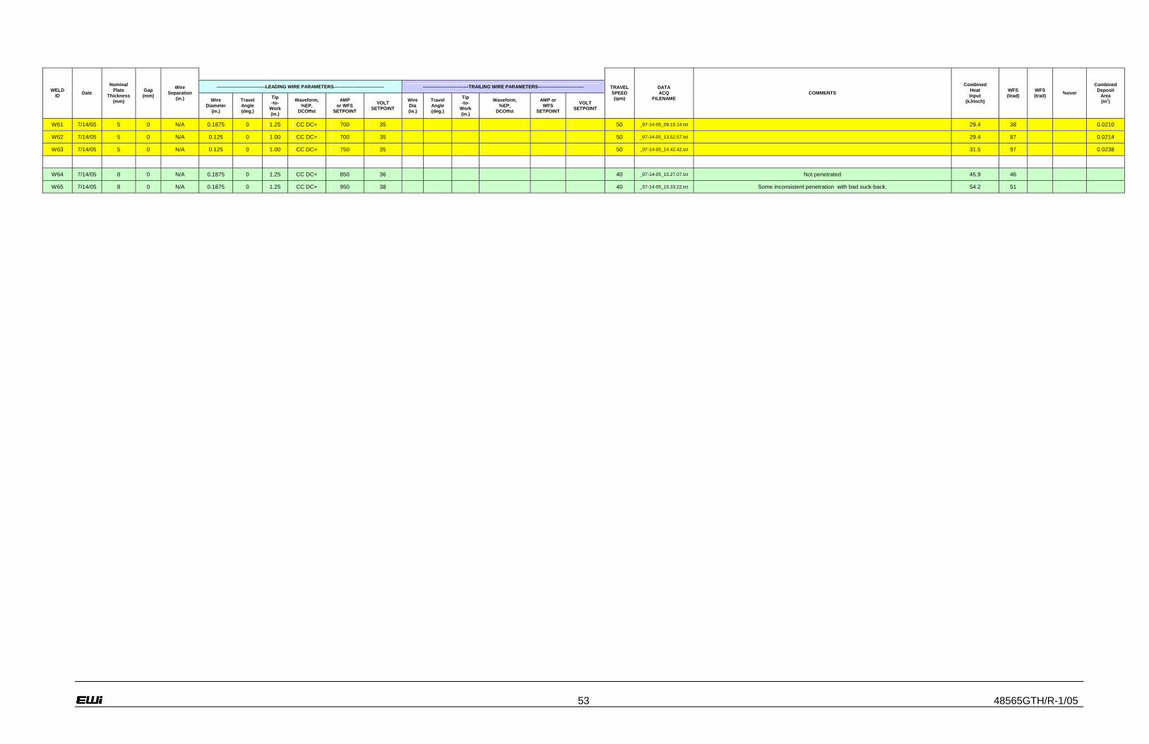
53 48565GTH/R-1/05
-------------------------------LEADING WIRE PARAMETERS-------------------------------- -----------------------------TRAILING WIRE PARAMETERS----------------------------- WELD
ID Date
Nominal Plate
Thickness (mm)
Gap (mm)
Wire Separation
(in.) Wire Diameter
(in.)
Travel Angle (deg.)
Tip -to-
Work (in.)
Waveform, %EP,
DCOffst
AMP or WFS
SETPOINT
VOLT SETPOINT
Wire Dia (in.)
Travel Angle (deg.)
Tip -to-
Work (in.)
Waveform, %EP,
DCOffst
AMP or WFS
SETPOINT
VOLT SETPOINT
TRAVEL SPEED (ipm)
DATA ACQ
FILENAME COMMENTS
Combined Heat Input
(kJ/inch)
WFS (lead)
WFS (trail) %over
Combined Deposit
Area (in2)
W61 7/14/05 5 0 N/A 0.1875 0 1.25 CC DC+ 700 35 50 _07-14-05_09.15.14.txt 29.4 38 0.0210
W62 7/14/05 5 0 N/A 0.125 0 1.00 CC DC+ 700 35 50 _07-14-05_13.52.57.txt 29.4 87 0.0214
W63 7/14/05 5 0 N/A 0.125 0 1.00 CC DC+ 750 35 50 _07-14-05_14.42.42.txt 31.5 97 0.0238
W64 7/14/05 8 0 N/A 0.1875 0 1.25 CC DC+ 850 36 40 _07-14-05_15.27.07.txt Not penetrated 45.9 46
W65 7/14/05 8 0 N/A 0.1875 0 1.25 CC DC+ 950 38 40 _07-14-05_15.33.22.txt Some inconsistent penetration with bad suck-back. 54.2 51

54 48565GTH/R-1/05
Appendix B – Improved FCB Groove Design Weld Parameters
-------------------------------LEADING WIRE PARAMETERS-------------------------------- -----------------------------TRAILING WIRE PARAMETERS----------------------------- WELD
ID Date
Nominal Plate
Thickness (mm)
Gap (mm)
Wire Separation
(in.) Wire Diameter
(in.)
Travel Angle (deg.)
Tip -to-
Work (in.)
Waveform, %EP,
DCOffst
AMP or WFS
SETPOINT
VOLT SETPOINT
Wire Dia. (in.)
Travel Angle (deg.)
Tip -to-
Work (in.)
Waveform, %EP,
DCOffst
AMP or WFS
SETPOINT
VOLT SETPOINT
TRAVEL SPEED (ipm)
DATA ACQ
FILENAME COMMENTS
Combined Heat Input
(kJ/inch)
WFS (lead)
WFS (trail) %over
Combined Deposit
Area (in2)
W66 8/9/05 8 2.9 to 3.1 N/A 0.15625 0 1.25 CC DC+ 750 34 17 _08-09-05_14.15.43.txt 90.0 58 0.0371
W67 8/9/05 8 2.9 to 3.1 0.78 0.15625 0 1.25 CC DC+ 750 34
0.0937
5 12 1.250
CC sq, bal=50%, DCOffs=0
500 34 30 _08-09-05_14.45.15.txt 85.0 62 172 0.0766
W68 8/9/05 8 3.0 to 3.2 0.78 0.15625 0 1.25 CC DC+ 750 34
0.0937
5 12 1.250
CC sq, bal=50%, DCOffs=0
500 34 35 _08-09-05_15.26.11.txt 72.9 62 172 0.0680
W69 8/9/05 8 3.2 to 3.3 0.78 0.15625 0 1.25 CC DC+ 750 34
0.0937
5 12 1.250
CC sq, bal=50%, DCOffs=0
500 34 40 _08-09-05_16.02.20.txt 63.8 62 177 0.0603
W70 8/16/05 5 1.8 to 1.4 N/A 0.15625 0 1.25 CC DC+ 650 33 30 _08-16-05_13.09.43.txt Single wire weld. Root side bead looks very good, strong penetration. Face side has no
reinforcement (flush) . Slag removed easily. 42.9 48
W71 8/16/05 5 1.8 to 2 0.78 0.15625 0 1.25 CC DC+ 650 33
0.0937
5 12 1.250
CC sq, bal=50%, DCOffs=0
500 34 40 _08-16-05_13.22.26.txt Burned into the copper backing. Probably the combined heat from 2 wires caused this. Another possibility that not enough flux is getting t the underside. 57.7 52 180
W72 8/17/05 5 1.7 to 1.6 0.78 0.15625 0 1.25 CC DC+ 550 32
0.0937
5 12 1.250
CC sq, bal=50%, DCOffs=0
400 33 40 _08-17-05_08.44.52.txt Still plenty of penetration. Some small melting to the copper. Face side scalloped and uneven.
Trail wire ran unstable with swings in the WFS. Since penetration is not a problem and stability is, try ac on lead torch.
46.2 41 140
W73 8/17/05 5 1.8 to 1.4 0.78 0.15625 0 1.25
CC sq, bal=50%, DCOffs=0
650 33 0.0937
5 12 1.250
CC sq, bal=50%, DCOffs=0
500 34 55 _08-17-05_14.18.12.txt Good bead. Stuck to the copper some at the run-on and run-off tabs which were nominally wider gap (~2.5 mm). 41.9 60 180
W74 8/18/05 10 3.8 to 3.9 0.78 N/A 0 1.25 CC DC+ 800 34 17 _08-18-05_13.40.59.txt Good penetration. Penetration goes away as joint gap closed up (probably closing a lot at slow
travel speed. 96.0 70
W75 8/18/05 10 2.8 to 3.8 0.78 0.15625 0 1.25 CC DC+ 800 34
0.0937
5 12 1.250
CC sq, bal=50%, DCOffs=0
500 34 30 _08-18-05_13.48.04.txt Good bead. Not a lot of excess penetration. A little suck-back @ start where gap was narrow, but quickly there's enough penetration. Didn't burn on the copper anywhere. 88.4 68 175
W76 8/18/05 10 3.8 to 3.9 0.78 0.15625 0 1.25 CC DC+ 800 34
0.0937
5 12 1.250
CC sq, bal=50%, DCOffs=0
500 34 30 _08-18-05_14.28.04.txt Repeat same parameters on a full 24"weld. 88.4 70 177
W77 8/18/05 10 3.9 0.78 0.15625 0 1.25 CC DC+ 850 34 0.0937
5 12 1.250
CC sq, bal=50%, DCOffs=0
500 34 35 _08-18-05_15.34.20.txt 78.7 76 180
Test baseline 8mm & 10mm parameters on varying gaps
W78 8/30/05 8 Var.
1.2 to 5.0
0.75 0.15625 0 1.25 CC DC+ 750 34 0.0937
5 12 1.25
CC sq, bal=50%, DCOffs=0
500 34 35 _08-30-05_14.26.43.txt Increasing gap test. RESULT: Weld did poorly. Speculation of why it went bad. 1) Hard start on previous attempt caused bent wire(s). 2) Primer and/or flux between the plate and copper bar my
prevent proper ground path. 72.9 0.0680
W79 8/30/05 8 3.6 to 3.4 0.75 0.15625 0 1.25 CC DC+ 750 34
0.0937
5 12 1.25
CC sq, bal=50%, DCOffs=0
500 34 35 _08-30-05_16.15.09.txt Try to repeat successful W68 (chosen baseline). Grind primer off back side. During weld, trail
wire became jammed in the spool and quit feeding. Lead wire continued ok. I stopped the weld midway through the plate.
72.9 0.0680
W80 8/31/05 8 2.9 to 3.3 0.75 0.15625 0 1.25 CC DC+ 750 34
0.0937
5 12 1.25
CC sq, bal=50%, DCOffs=0
500 34 35 _08-31-05_08.33.24.txt Fixed jammed wire and continue repeat of W68 parameters on remainder of plate (primer ground off back side). RESULT: Good. Penetration is light at the start (where the gap is narrower). Top
side looks good. 72.9 62 172 0.0680
W81 8/31/05 8 Var.
1.6 to 5.5
0.75 0.15625 0 1.25 CC DC+ 750 34 0.0937
5 12 1.25
CC sq, bal=50%, DCOffs=0
500 34 35 _08-31-05_10.39.52.txt Increasing gap test. Ground primer off back side. RESULT: Good. Penetrated all the way and did not burn the copper anywhere. Less penetration at mid plate, indicating it is still pulling in. 72.9 0.0680
W82 8/31/05 8 Var.
5.5 to 1.5
0.75 0.15625 0 1.25 CC DC+ 750 34 0.0937
5 12 1.25
CC sq, bal=50%, DCOffs=0
500 34 35 _08-31-05_14.34.32.txt Decreasing gap test. Ground primer off back side. RESULT: Good. Penetrated all the way and did not burn the copper anywhere. Less penetration at mid plate, indicating it is still pulling in. 72.9 0.0680
W83 8/31/05 10 Var.
2.0 to 5.7
0.78 0.15625 0 1.25 CC DC+ 800 34 0.0937
5 12 1.250
CC sq, bal=50%, DCOffs=0
500 34 30 _08-31-05_15.13.36.txt Increasing gap test. Ground primer off back side. RESULT: Good. Penetrated all the way and did not burn the copper anywhere. 88.4
W84 9/1/05 10 Var.
6.0 to 1.5
0.78 0.15625 0 1.25 CC DC+ 800 34 0.0937
5 12 1.250
CC sq, bal=50%, DCOffs=0
500 34 30 _09-01-05_10.27.52.txt Decreasing gap test. Ground primer off back side. RESULT: Good. Penetrated most of the way and did not burn the copper anywhere. Missing penetration 2/3 of the way, (before the narrowest
part), indicating it is still pulling in. 88.4
Try to develop tandem on 5mm with zero gap using the .75 x .09 round copper back.

55 48565GTH/R-1/05
-------------------------------LEADING WIRE PARAMETERS-------------------------------- -----------------------------TRAILING WIRE PARAMETERS----------------------------- WELD
ID Date
Nominal Plate
Thickness (mm)
Gap (mm)
Wire Separation
(in.) Wire Diameter
(in.)
Travel Angle (deg.)
Tip -to-
Work (in.)
Waveform, %EP,
DCOffst
AMP or WFS
SETPOINT
VOLT SETPOINT
Wire Dia. (in.)
Travel Angle (deg.)
Tip -to-
Work (in.)
Waveform, %EP,
DCOffst
AMP or WFS
SETPOINT
VOLT SETPOINT
TRAVEL SPEED (ipm)
DATA ACQ
FILENAME COMMENTS
Combined Heat Input
(kJ/inch)
WFS (lead)
WFS (trail) %over
Combined Deposit
Area (in2)
W85 9/1/05 5 0 0.78 0.15625 0 1.50 CC DC+ 650 33 0.0937
5 12 1.250
CC sq, bal=50%, DCOffs=0
500 34 55 _09-01-05_12.37.26.txt
APPROACH: Same parameters that over-penetrated on W96 run on tight joint fit up. Tacks each end and one in the middle. Ground primer off back side. Flush layer of flux in the backing recess.
Mistakenly had the CTWD=1.50". RESULT: Some flare-ups and instability on the lead wire. Penetration was light. Lost penetration midway through. This could be due to the tack and the fact
that the penetration is minimal. Looks like lead wire is not doing the penetration.
41.9 52 180
W86 9/1/05 5 0 0.78 0.15625 0 1.25 CC DC+ 725 34 0.0937
5 12 1.250
CC sq, bal=50%, DCOffs=0
400 32 55 _09-01-05_14.07.02.txt
APPROACH: In reviewing W62 & W63, single wire penetrated, so choose current between these. Keep current low on trail torch to keep deposit area down. Tacks each end and one in the middle. Ground primer off back side. Flush layer of flux in the backing recess. Result: Data trace shows it
didn't run real stable. Lost penetration midway through again. This is odd because we thought the reason why gap pulling in, but this had no gap. Maybe a grounding issue because it happened
exactly between the first and second set of hold-down blocks.
40.9 52 180
Setup insulator on back of copper backing bar to isolate the fixture from the welding circuit
W87 9/6/05 5 0 0.78 0.15625 0 1.25 CC DC+ 725 34 0.0937
5 12 1.250
CC sq, bal=50%, DCOffs=0
400 32 55 _09-06-05_15.59.30.txt
PURPOSE: Test the new grounding setup and compare with previous weld. APPROACH: Repeat W86, but no grinding of the primer on the root side, and trying the insulated copper bar. Tacks each end and one in the middle. Flush layer of flux in the backing recess. RESULT: Ran
very poorly, unstable. Penetration intermittent and weak. Lead arc was unstable.
40.9 52 180
Is the instability due to isolating the current path to the copper bar, or is it lack of good ground due to the primer coating? Since the best results so far have been on 8 or 10 mm plate, I'll try baseline
procedure, but make sure primer is still on the back side.
W88 9/7/05 10 3.9 to 4.0 0.78 0.15625 0 1.25 CC DC+ 800 34
0.0937
5 12 1.250
CC sq, bal=50%, DCOffs=0
500 34 30 _09-07-05_08.54.18.txt
PURPOSE: See if primer between the plate and isolated copper block causes the instability. APPROACH: Repeat W76, but no grinding of the primer on the root side. Run-on/off tabs little
grinding and do not clamp to the run-on/off tabs as this is a direct path from the copper bar through the clamps. RESULT: Good, stable weld. Bead looks good, root looks good.
88.4 70 180 0.0738
W89 9/7/05 8 3.4 to 3.2 0.78 0.15625 0 1.25 CC DC+ 750 34
0.0937
5 12 1.250
CC sq, bal=50%, DCOffs=0
500 34 35 _09-07-05_10.48.46.txt
PURPOSE: See if primer between the plate and isolated copper block causes the instability. APPROACH: Repeat W68, but no grinding of the primer on the root side. Run-on/off tabs little
grinding and do not clamp to the run-on/off tabs as this is a direct path from the copper bar through the clamps. Copper bar isolated. RESULT: Good, stable weld. Bead looks good, root looks good.
72.9 62 178 0.0691
W90 9/7/05 5 1.9 to 2.0 0.78 0.15625 0 1.25
CC sq, bal=50%, DCOffs=0
650 33 0.0937
5 12 1.250
CC sq, bal=50%, DCOffs=0
500 34 55 _09-07-05_13.13.41.txt
PURPOSE: See if primer between the plate and isolated copper block causes the instability. APPROACH: Repeat W73, but no grinding of the primer on the root side. Run-on/off tabs little
grinding and do not clamp to the run-on/off tabs as this is a direct path from the copper bar through the clamps. Copper bar isolated. RESULT: Good, stable weld. Bead looks good, root looks good.
41.9 60 175 0.0249
Zero gap attempts on 5 mm plate
W91 9/7/05 5 0 0.78 0.15625 0 1.25 CC DC+ 725 34 0.0937
5 12 1.250
CC sq, bal=50%, DCOffs=0
400 32 55 _09-07-05_14.59.36.txt
PURPOSE: Test same setup as W88-90 on a no-gap 5mm plate. APPROACH: Repeat W86, W87 parameters. No grinding of the primer on the root side. Use run-on/off tabs with little
grinding and do not clamp to the run-on/off tabs as this is a direct path from the copper bar through the clamps. Copper bar isolated. RESULT: Ran much better than W87, lead arc was stable, but
bead appearance is irregular. Most of weld good penetration. but some places where it not penetrated well. Inconsistent.
40.9 59 135 0.0375
W92 9/7/05 5 0 N/A 0.15625 0 1.00 CC sq,
bal=50%, DCOffs=0
650 35 32 _09-07-05_15.55.35.txt
PURPOSE: Test single wire AC param's on the round .75" x .090" backing groove. APPROACH: Similar to Nick's parameters, but Square Wave and using 5/32" wire and the round back groove. No run-on/off tabs. I ground off primer from the back to get plate grounded, but left primer in the
joint area. RESULT: Very stable. Very good bead front side and back.
42.7 59 0 0.0354
W93 9/7/05 5 0 0.78 0.15625 0 1.25 CC DC+ 650 34 0.0937
5 12 1.250
CC sq, bal=50%, DCOffs=0
400 32 45 _09-07-05_17.18.13.txt
PURPOSE: Try to improve on consistency of W91, no-gap tandem. APPROACH: Reduce travel speed and try to keep same deposit area as W91. RESULT: Some improvement over W91.
Burned the copper and stuck some on the run-on tab. Fully penetrated all the way. Front side somewhat inconsistent. This is not the level of quality that the single wire procedure (W92)
produced.
46.5 51 140 0.0432
Try develop base procedures on 10 mm that utilize AC/AC

56 48565GTH/R-1/05
-------------------------------LEADING WIRE PARAMETERS-------------------------------- -----------------------------TRAILING WIRE PARAMETERS----------------------------- WELD
ID Date
Nominal Plate
Thickness (mm)
Gap (mm)
Wire Separation
(in.) Wire Diameter
(in.)
Travel Angle (deg.)
Tip -to-
Work (in.)
Waveform, %EP,
DCOffst
AMP or WFS
SETPOINT
VOLT SETPOINT
Wire Dia. (in.)
Travel Angle (deg.)
Tip -to-
Work (in.)
Waveform, %EP,
DCOffst
AMP or WFS
SETPOINT
VOLT SETPOINT
TRAVEL SPEED (ipm)
DATA ACQ
FILENAME COMMENTS
Combined Heat Input
(kJ/inch)
WFS (lead)
WFS (trail) %over
Combined Deposit
Area (in2)
W94 9/14/05 10 3.8 to 4.0 0.78 0.15625 0 1.25
CC sq, 45 Hz,
bal=50%, DCOffs=0
800 34 0.0937
5 12 1.250
CC sq, bal=50%, DCOffs=0, Phase=90
500 34 30 _09-14-05_13.40.44.txt APPROACH: Same param's as baseline 10 mm (W76), but Balanced AC on lead torch. RESULT: Note 45 Hz frequency. Ran a little unstable, flare ups. Penetrated all the way, but penetration is
not as strong as W76. In some places negative reinforcement or sucked back a little. 88.4 87 185 0.0982
W95 9/14/05 10 3.6 to 3.9 0.78 0.15625 0 1.25
CC sq, 45 Hz,
bal(+)=70%,
DCOffs=+7500
800 34 0.125 9.5 1.250
CC sq, bal=50%, DCOffs=0, Phase=123
500 35 30 _09-14-05_15.19.43.txt APPROACH: Positive balance and some positive offset on lead torch to get more penetration.
RESULT: Note 45 Hz frequency. Ran more unstable than W94. Flare ups and spiking of the slag. In some places negative reinforcement or sucked back a little.
89.4 75 185 0.0905
Taking distortion measurements of baseline welds
W96 10/21/05 5 1.9 to
2.0 0.78 0.15625 0 1.25 CC sq,
bal=50%, DCOffs=0
650 33 0.0937
5 12 1.250
CC sq, bal=50%, DCOffs=0
500 34 55 _10-21-05_10.06.59.txt Good weld. A lot of bowing distortion in the opposite direction expected. 41.9 60 180 0.0435
W97 10/21/05 8 3.4 to
3.3 0.78 0.15625 0 1.25 CC DC+ 750 34 0.0937
5 12 1.250
CC sq, bal=50%, DCOffs=0
500 34 35 _10-21-05_11.01.49.txt Good bead. Minimal distortion. 72.9 62 175
W98 10/21/05 10 3.8 to
4.0 0.78 0.15625 0 1.25 CC DC+ 800 34 0.0937
5 12 1.250
CC sq, bal=50%, DCOffs=0
500 34 30 _10-21-05_13.03.36.txt Good bead. Minimal distortion. 88.4 70 175
Test baseline 8mm & 10mm parameters on small & large gaps
W99 10/21/05 8 2.1 to
2.2 0.78 0.15625 0 1.25 CC DC+ 750 34 0.0937
5 12 1.250
CC sq, bal=50%, DCOffs=0
500 34 35 _10-21-05_14.54.07.txt 72.9 61 172
W100 10/21/05 8 5.2 to
5.0 0.78 0.15625 0 1.25 CC DC+ 750 34 0.0937
5 12 1.250
CC sq, bal=50%, DCOffs=0
500 34 35 _10-21-05_15.56.05.txt 72.9 63 182
W101 10/24/05 10 3.0 to
2.9 0.78 0.15625 0 1.25 CC DC+ 800 34 0.0937
5 12 1.250
CC sq, bal=50%, DCOffs=0
500 34 30 _10-24-05_10.00.04.txt 88.4 68 173
W102 10/24/05 10 5.9 to
6.0 0.78 0.15625 0 1.25 CC DC+ 800 34 0.0937
5 12 1.250
CC sq, bal=50%, DCOffs=0
500 34 30 _10-24-05_12.36.22.txt Ran a little unstable. Stuck to copper backing in a few places. Good penetration, front face is somewhat ropey with little or no reinforcement 88.4 73 185
W103 10/24/05 10 3.8 to
3.9 0.78 0.15625 0 1.25
CC sq, 65 Hz,
bal(+)=70%,
DCOffs=+7500
700 32 0.0937
5 12 1.250
CC sq, bal=50%, DCOffs=0,
Phase=123 deg
400 32 25 _10-24-05_16.36.08.txt
APPROACH: More conservative parameters (less current, slower travel). Positive balance and some positive offset on lead torch to get more penetration. RESULT: Note 65 Hz frequency. Ran stable. A little less penetration than the procedure with DC+ lead torch. Penetrated all the way.
but minimal root side reinforcement and some suck-back at 2/3 of the way where gap has pulled in most.
84.5 62 135 0.0850
Try reduce heat input for 5 mm plate
W104 10/25/05 5 3.1 to
3.2 0.78 0.15625 0 1.25 CC sq,
bal=50%, DCOffs=0
550 32 0.0937
5 12 1.250
CC sq, bal=50%, DCOffs=0
500 33 55 _10-25-05_14.26.07.txt
PURPOSE: Improve on baseline 5mm plate parameters (W73). Foremost, reduce heat input, secondly, decrease the height-to-width ratio of the underbead. APPROACH: Wider gap so that it can penetrate at lower current. RESULT: Ran very stable. There were two holes (skips) in the weld. Underbead good except for the holes where it skipped. Data shows that arc was ok, wfs
was ok, and the hole simply from lacking enough fill. Some sticking to the copper. Plenty of penetration.
37.2 48 180 0.0393
W105 10/25/05 5 3.3 0.78 0.15625 0 1.25
CC sq, bal=50%, DCOffs=-
8200
550 32 0.0937
5 12 1.250
CC sq, bal(+)=45%,
DCOffs=-8200, Phase=100 deg
500 33 55 _10-25-05_16.17.20.txt
PURPOSE: Improve on baseline 5mm plate parameters (W73). Eliminate holes seen on W104. APPROACH: Increase EN (wfs should increase) on both wires. RESULT: Ran very stable.
Again there were two holes (skips) in the weld but further apart this time. Underbead good except for the holes where it skipped. Data shows that arc was ok, wfs was ok, and the hole simply from
lacking enough fill. No sticking to the copper. Still plenty of penetration. This seems to have helped, but it didn't have as much effect on adding more wire as I had hoped for.
37.2 50 185 0.0407
W106 10/26/05 5 3.1
to 3.4 0.78 0.15625 0 1.50
CC sq, bal=50%, DCOffs=-
8200
550 32 0.0937
5 12 1.250
CC sq, bal(+)=40%,
DCOffs=-8200, Phase=105 deg
500 33 55 _10-26-05_08.53.46.txt
PURPOSE: Improve on baseline 5mm plate parameters (W73). Eliminate holes seen on W104. APPROACH: Increase EN on trail wire and increase stickout on lead wire (wfs should increase) RESULT: Ran very stable. This time just one hole (skip) in the weld which took longer before it developed. Underbead good except for the hole where it skipped. Data shows that arc was ok,
wfs was ok, and the hole simply from lacking enough fill. No sticking to the copper. Still plenty of penetration. This seems to have helped again, but again the effect of adding more wire is smaller
than desired.
37.2 51 190 0.0416
W107 10/26/05 5 1.9 to
2.1 0.78 0.15625 0 1.25
CC sq, bal=50%, DCOffs=-
8200
550 32 0.0937
5 12 1.250
CC sq, bal(+)=40%,
DCOffs=-8200, Phase=105 deg
500 33 55 _10-26-05_13.22.10.txt
PURPOSE: Improve on baseline 5mm plate parameters (W73). See how lower heat input param's work on the 2 mm gap.. APPROACH: Try same param's on 2 mm gap. RESULT: Somewhat
unstable. No holes. Underbead started out good but penetration went away. No sticking to the copper. Not enough heat to penetrate this gap.
37.2 50 185 0.0407

57 48565GTH/R-1/05
-------------------------------LEADING WIRE PARAMETERS-------------------------------- -----------------------------TRAILING WIRE PARAMETERS----------------------------- WELD
ID Date
Nominal Plate
Thickness (mm)
Gap (mm)
Wire Separation
(in.) Wire Diameter
(in.)
Travel Angle (deg.)
Tip -to-
Work (in.)
Waveform, %EP,
DCOffst
AMP or WFS
SETPOINT
VOLT SETPOINT
Wire Dia. (in.)
Travel Angle (deg.)
Tip -to-
Work (in.)
Waveform, %EP,
DCOffst
AMP or WFS
SETPOINT
VOLT SETPOINT
TRAVEL SPEED (ipm)
DATA ACQ
FILENAME COMMENTS
Combined Heat Input
(kJ/inch)
WFS (lead)
WFS (trail) %over
Combined Deposit
Area (in2)
Conclusion: It seems that reducing the heat input from the nominal 43 kJ/inch (W73) makes a tight window on the gap tolerance. At 3mm gap, holes, at 2mm, not enough penetration. Try the 43
kJ/inch parameters with some EN. This should give a little more deposit which would help widen the gap tolerance.
W108 10/27/05 5 1.9 to
2.0 0.78 0.15625 0 1.25
CC sq, bal=50%, DCOffs=-
8200
650 33 0.0937
5 12 1.250
CC sq, bal(+)=40%,
DCOffs=-8200, Phase=105 deg
500 33 55 _10-27-05_08.35.19.txt
PURPOSE: Improve on baseline 5mm plate parameters (W73). APPROACH: Try similar to W73 param's but with added EN similar to W105 on 2 mm gap. RESULT: Ran stable. Good balance of bead size on front & back. Plate can buckle either direction. Good bead shape front & back.
No sticking to the copper.
41.4 60 190 0.0448
W109 10/27/05 5 1.3 to
1.4 0.78 0.15625 0 1.25
CC sq, bal=50%, DCOffs=-
8200
650 33 0.0937
5 12 1.250
CC sq, bal(+)=40%,
DCOffs=-8200, Phase=105 deg
500 33 55 _10-27-05_09.20.26.txt
PURPOSE: Test gap tolerance of parameters W108. APPROACH: Same as W108, but narrower gap. RESULT: Ran somewhat unstable. Penetrated all the way, but penetration is minimal with
little or no reinforcement on root side. Most of the weld deposited on the front causing a lot of distortion in that direction.. No sticking to the copper.
41.4 60 190 0.0448
W110 10/27/05 5 2.9 to
3.0 0.78 0.15625 0 1.25
CC sq, bal=50%, DCOffs=-
8200
650 33 0.0937
5 12 1.250
CC sq, bal(+)=40%,
DCOffs=-8200, Phase=105 deg
500 33 55 _10-27-05_10.43.12.txt
PURPOSE: Test gap tolerance of parameters W108. APPROACH: Same as W108, but wider gap. RESULT: Ran stable. Good balance of bead size on front & back. Plate can buckle either direction. Good bead shape front & back. A hole formed at end of weld just before the run-off
tab. I don't know if this is due to the transition to the run-off or if because procedure not tolerant to 3 mm gap. No sticking to the copper.
41.4 60 194 0.0453

58 48565GTH/R-1/05
Appendix C – DC Offset Trends
Tandem Trials : Lead 750A/34V , Trail 500A/34V , Travel=35ipm
BOP # Offset Value Resulting WFS Average CurrentAverage V,I,WFS data file (.txt)
HS data file (.dat)
2 19599 140 9/8/2005 9:533 32767 133 9/8/2005 10:124 -32767 168 9/8/2005 10:245 0 168 9/8/2005 12:486 -24500 165 9/8/2005 12:587 24500 133 9/8/2005 13:108 16500 143 9/8/2005 13:279 7500 156 9/8/2005 14:07
10 0 168 9/8/2005 14:3511 -7500 171 -114 9/8/2005 15:10 Test115 -16500 167 -240 9/9/2005 8:18 Test516 -24500 167 -245 9/9/2005 8:37 Test617 -32767 169 -250 9/9/2005 8:58 Test718 0 171 -18 9/9/2005 9:14 Test819 5000 158 51 9/9/2005 9:30 Test920 10000 156 116 9/9/2005 10:06 Test1021 24500 135 240 9/9/2005 10:40 Test11
Single Wire trials: 500A/34V , Travel=22 ipm12 0 150 22 9/8/2005 15:21 Test213 -7500 150 -80 9/8/2005 15:33 Test314 -16500 147 -218 9/8/2005 15:38 Test4

59 48565GTH/R-1/05
Appendix D – ROMER Arm Distortion Measurements: 5-mm Before Weld
RP 1
Lo. Tol. Hi. Tol. Nominal Measured Dev/Mean Error
X 0.000 0.000 7.054 7.054 0.000 0.000
Target point Y 0.000 0.000 28.220 28.220 0.000
Z 0.000 0.000 0.252 0.252 0.000 0.000
Distance To Target Point -0.100 0.100 0.000 0.000 0.000
Distance to Target Plane -0.100 0.100 0.000 0.000 0.000
Distance On Plane -0.100 0.100 0.000 0.000 0.000
RP 2
Lo. Tol. Hi. Tol. Nominal Measured Dev/Mean Error
X 0.000 0.000 10.046 10.046 0.000
Target point Y 0.000 0.000 28.195 28.195 0.000
Z 0.000 0.000 0.266 0.266 0.000 0.000
Distance To Target Point -0.100 0.100 0.000 0.000 0.000
Distance to Target Plane -0.100 0.100 0.000 0.000 0.000
Distance On Plane -0.100 0.100 0.000 0.000 0.000
RP 3
Lo. Tol. Hi. Tol. Nominal Measured Dev/Mean Error
X 0.000 0.000 13.193 13.193 0.000
Target point Y 0.000 0.000 28.206 28.206 0.000
Z 0.000 0.000 0.275 0.275 0.000 0.000
Distance To Target Point -0.100 0.100 0.000 0.000 0.000
Distance to Target Plane -0.100 0.100 0.000 0.000 0.000
Distance On Plane -0.100 0.100 0.000 0.000 0.000
RP 4
Lo. Tol. Hi. Tol. Nominal Measured Dev/Mean Error
X 0.000 0.000 16.334 16.334 0.000
Target point Y 0.000 0.000 28.270 28.270 0.000
Z 0.000 0.000 0.280 0.280 0.000
Distance To Target Point -0.100 0.100 0.000 0.000 0.000
Distance to Target Plane -0.100 0.100 0.000 0.000 0.000
Distance On Plane -0.100 0.100 0.000 0.000 0.000
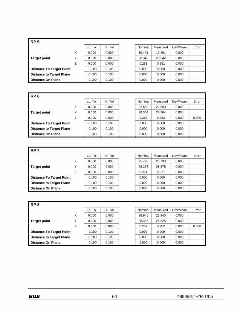
60 48565GTH/R-1/05
RP 5
Lo. Tol. Hi. Tol. Nominal Measured Dev/Mean Error
X 0.000 0.000 19.491 19.491 0.000
Target point Y 0.000 0.000 28.342 28.342 0.000
Z 0.000 0.000 0.281 0.281 0.000
Distance To Target Point -0.100 0.100 0.000 0.000 0.000
Distance to Target Plane -0.100 0.100 0.000 0.000 0.000
Distance On Plane -0.100 0.100 0.000 0.000 0.000
RP 6
Lo. Tol. Hi. Tol. Nominal Measured Dev/Mean Error
X 0.000 0.000 22.659 22.659 0.000
Target point Y 0.000 0.000 28.304 28.304 0.000
Z 0.000 0.000 0.283 0.283 0.000 0.000
Distance To Target Point -0.100 0.100 0.000 0.000 0.000
Distance to Target Plane -0.100 0.100 0.000 0.000 0.000
Distance On Plane -0.100 0.100 0.000 0.000 0.000
RP 7
Lo. Tol. Hi. Tol. Nominal Measured Dev/Mean Error
X 0.000 0.000 25.793 25.793 0.000
Target point Y 0.000 0.000 28.278 28.278 0.000
Z 0.000 0.000 0.271 0.271 0.000
Distance To Target Point -0.100 0.100 0.000 0.000 0.000
Distance to Target Plane -0.100 0.100 0.000 0.000 0.000
Distance On Plane -0.100 0.100 0.000 0.000 0.000
RP 8
Lo. Tol. Hi. Tol. Nominal Measured Dev/Mean Error
X 0.000 0.000 28.945 28.945 0.000
Target point Y 0.000 0.000 28.325 28.325 0.000
Z 0.000 0.000 0.252 0.252 0.000 0.000
Distance To Target Point -0.100 0.100 0.000 0.000 0.000
Distance to Target Plane -0.100 0.100 0.000 0.000 0.000
Distance On Plane -0.100 0.100 0.000 0.000 0.000
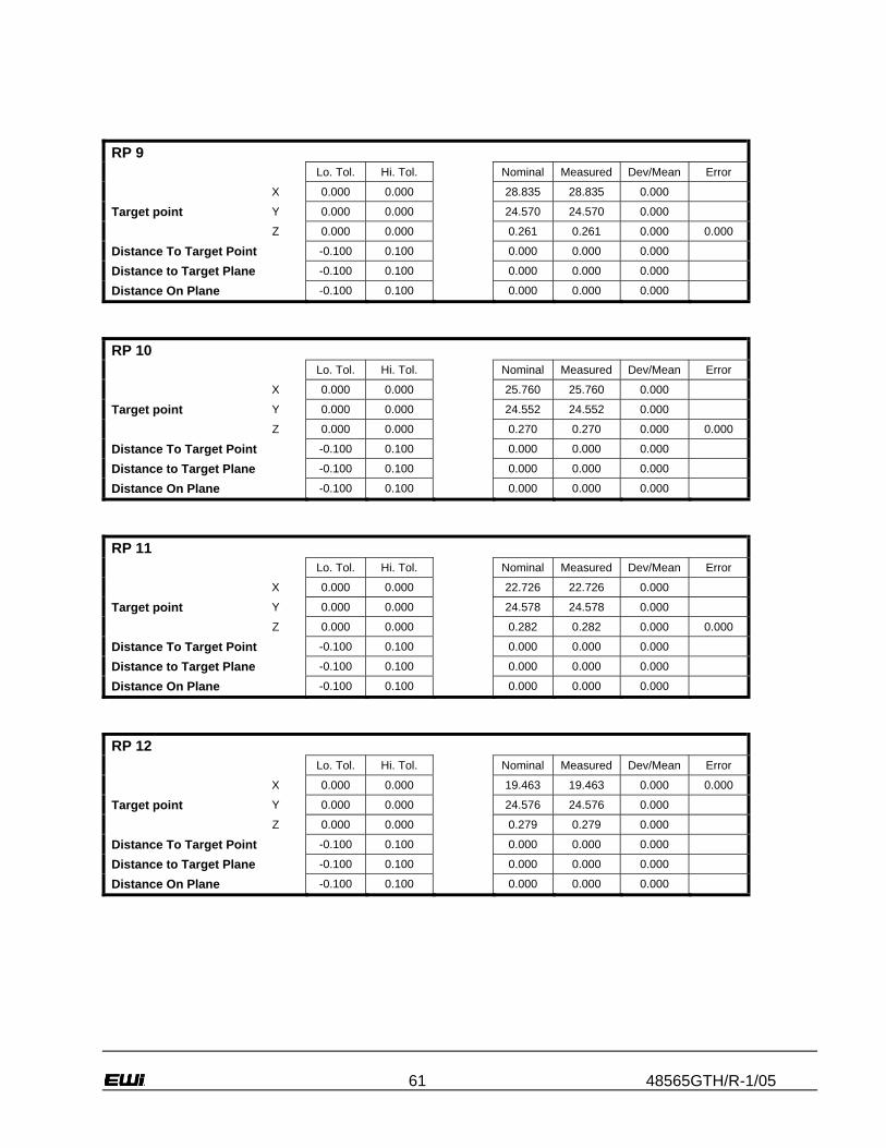
61 48565GTH/R-1/05
RP 9
Lo. Tol. Hi. Tol. Nominal Measured Dev/Mean Error
X 0.000 0.000 28.835 28.835 0.000
Target point Y 0.000 0.000 24.570 24.570 0.000
Z 0.000 0.000 0.261 0.261 0.000 0.000
Distance To Target Point -0.100 0.100 0.000 0.000 0.000
Distance to Target Plane -0.100 0.100 0.000 0.000 0.000
Distance On Plane -0.100 0.100 0.000 0.000 0.000
RP 10
Lo. Tol. Hi. Tol. Nominal Measured Dev/Mean Error
X 0.000 0.000 25.760 25.760 0.000
Target point Y 0.000 0.000 24.552 24.552 0.000
Z 0.000 0.000 0.270 0.270 0.000 0.000
Distance To Target Point -0.100 0.100 0.000 0.000 0.000
Distance to Target Plane -0.100 0.100 0.000 0.000 0.000
Distance On Plane -0.100 0.100 0.000 0.000 0.000
RP 11
Lo. Tol. Hi. Tol. Nominal Measured Dev/Mean Error
X 0.000 0.000 22.726 22.726 0.000
Target point Y 0.000 0.000 24.578 24.578 0.000
Z 0.000 0.000 0.282 0.282 0.000 0.000
Distance To Target Point -0.100 0.100 0.000 0.000 0.000
Distance to Target Plane -0.100 0.100 0.000 0.000 0.000
Distance On Plane -0.100 0.100 0.000 0.000 0.000
RP 12
Lo. Tol. Hi. Tol. Nominal Measured Dev/Mean Error
X 0.000 0.000 19.463 19.463 0.000 0.000
Target point Y 0.000 0.000 24.576 24.576 0.000
Z 0.000 0.000 0.279 0.279 0.000
Distance To Target Point -0.100 0.100 0.000 0.000 0.000
Distance to Target Plane -0.100 0.100 0.000 0.000 0.000
Distance On Plane -0.100 0.100 0.000 0.000 0.000

62 48565GTH/R-1/05
RP 13
Lo. Tol. Hi. Tol. Nominal Measured Dev/Mean Error
X 0.000 0.000 16.345 16.345 0.000 0.000
Target point Y 0.000 0.000 24.592 24.592 0.000
Z 0.000 0.000 0.278 0.278 0.000 0.000
Distance To Target Point -0.100 0.100 0.000 0.000 0.000
Distance to Target Plane -0.100 0.100 0.000 0.000 0.000
Distance On Plane -0.100 0.100 0.000 0.000 0.000
RP 14
Lo. Tol. Hi. Tol. Nominal Measured Dev/Mean Error
X 0.000 0.000 13.239 13.239 0.000
Target point Y 0.000 0.000 24.592 24.592 0.000
Z 0.000 0.000 0.273 0.273 0.000 0.000
Distance To Target Point -0.100 0.100 0.000 0.000 0.000
Distance to Target Plane -0.100 0.100 0.000 0.000 0.000
Distance On Plane -0.100 0.100 0.000 0.000 0.000
RP 15
Lo. Tol. Hi. Tol. Nominal Measured Dev/Mean Error
X 0.000 0.000 10.099 10.099 0.000
Target point Y 0.000 0.000 24.573 24.573 0.000
Z 0.000 0.000 0.263 0.263 0.000 0.000
Distance To Target Point -0.100 0.100 0.000 0.000 0.000
Distance to Target Plane -0.100 0.100 0.000 0.000 0.000
Distance On Plane -0.100 0.100 0.000 0.000 0.000
RP 16
Lo. Tol. Hi. Tol. Nominal Measured Dev/Mean Error
X 0.000 0.000 6.980 6.980 0.000 0.000
Target point Y 0.000 0.000 24.623 24.623 0.000
Z 0.000 0.000 0.250 0.250 0.000
Distance To Target Point -0.100 0.100 0.000 0.000 0.000
Distance to Target Plane -0.100 0.100 0.000 0.000 0.000
Distance On Plane -0.100 0.100 0.000 0.000 0.000

63 48565GTH/R-1/05
RP 17
Lo. Tol. Hi. Tol. Nominal Measured Dev/Mean Error
X 0.000 0.000 7.013 7.013 0.000 0.000
Target point Y 0.000 0.000 22.381 22.381 0.000
Z 0.000 0.000 0.249 0.249 0.000 0.000
Distance To Target Point -0.100 0.100 0.000 0.000 0.000
Distance to Target Plane -0.100 0.100 0.000 0.000 0.000
Distance On Plane -0.100 0.100 0.000 0.000 0.000
RP 18
Lo. Tol. Hi. Tol. Nominal Measured Dev/Mean Error
X 0.000 0.000 10.114 10.114 0.000 0.000
Target point Y 0.000 0.000 22.316 22.316 0.000
Z 0.000 0.000 0.260 0.260 0.000
Distance To Target Point -0.100 0.100 0.000 0.000 0.000
Distance to Target Plane -0.100 0.100 0.000 0.000 0.000
Distance On Plane -0.100 0.100 0.000 0.000 0.000
RP 19
Lo. Tol. Hi. Tol. Nominal Measured Dev/Mean Error
X 0.000 0.000 13.217 13.217 0.000
Target point Y 0.000 0.000 22.392 22.392 0.000
Z 0.000 0.000 0.264 0.264 0.000 0.000
Distance To Target Point -0.100 0.100 0.000 0.000 0.000
Distance to Target Plane -0.100 0.100 0.000 0.000 0.000
Distance On Plane -0.100 0.100 0.000 0.000 0.000
RP 20
Lo. Tol. Hi. Tol. Nominal Measured Dev/Mean Error
X 0.000 0.000 16.396 16.396 0.000
Target point Y 0.000 0.000 22.424 22.424 0.000
Z 0.000 0.000 0.265 0.265 0.000 0.000
Distance To Target Point -0.100 0.100 0.000 0.000 0.000
Distance to Target Plane -0.100 0.100 0.000 0.000 0.000
Distance On Plane -0.100 0.100 0.000 0.000 0.000

64 48565GTH/R-1/05
RP 21
Lo. Tol. Hi. Tol. Nominal Measured Dev/Mean Error
X 0.000 0.000 19.440 19.440 0.000
Target point Y 0.000 0.000 22.387 22.387 0.000
Z 0.000 0.000 0.261 0.261 0.000
Distance To Target Point -0.100 0.100 0.000 0.000 0.000
Distance to Target Plane -0.100 0.100 0.000 0.000 0.000
Distance On Plane -0.100 0.100 0.000 0.000 0.000
RP 22
Lo. Tol. Hi. Tol. Nominal Measured Dev/Mean Error
X 0.000 0.000 22.677 22.677 0.000
Target point Y 0.000 0.000 22.355 22.355 0.000
Z 0.000 0.000 0.269 0.269 0.000
Distance To Target Point -0.100 0.100 0.000 0.000 0.000
Distance to Target Plane -0.100 0.100 0.000 0.000 0.000
Distance On Plane -0.100 0.100 0.000 0.000 0.000
RP 23
Lo. Tol. Hi. Tol. Nominal Measured Dev/Mean Error
X 0.000 0.000 25.712 25.712 0.000
Target point Y 0.000 0.000 22.382 22.382 0.000
Z 0.000 0.000 0.271 0.271 0.000
Distance To Target Point -0.100 0.100 0.000 0.000 0.000
Distance to Target Plane -0.100 0.100 0.000 0.000 0.000
Distance On Plane -0.100 0.100 0.000 0.000 0.000
RP 24
Lo. Tol. Hi. Tol. Nominal Measured Dev/Mean Error
X 0.000 0.000 28.867 28.867 0.000
Target point Y 0.000 0.000 22.372 22.372 0.000
Z 0.000 0.000 0.265 0.265 0.000
Distance To Target Point -0.100 0.100 0.000 0.000 0.000
Distance to Target Plane -0.100 0.100 0.000 0.000 0.000
Distance On Plane -0.100 0.100 0.000 0.000 0.000

65 48565GTH/R-1/05
RP 25
Lo. Tol. Hi. Tol. Nominal Measured Dev/Mean Error
X 0.000 0.000 28.837 28.837 0.000
Target point Y 0.000 0.000 18.662 18.662 0.000
Z 0.000 0.000 0.251 0.251 0.000
Distance To Target Point -0.100 0.100 0.000 0.000 0.000
Distance to Target Plane -0.100 0.100 0.000 0.000 0.000
Distance On Plane -0.100 0.100 0.000 0.000 0.000
RP 26
Lo. Tol. Hi. Tol. Nominal Measured Dev/Mean Error
X 0.000 0.000 25.789 25.789 0.000
Target point Y 0.000 0.000 18.650 18.650 0.000
Z 0.000 0.000 0.254 0.254 0.000
Distance To Target Point -0.100 0.100 0.000 0.000 0.000
Distance to Target Plane -0.100 0.100 0.000 0.000 0.000
Distance On Plane -0.100 0.100 0.000 0.000 0.000
RP 27
Lo. Tol. Hi. Tol. Nominal Measured Dev/Mean Error
X 0.000 0.000 22.670 22.670 0.000
Target point Y 0.000 0.000 18.594 18.594 0.000
Z 0.000 0.000 0.259 0.259 0.000
Distance To Target Point -0.100 0.100 0.000 0.000 0.000
Distance to Target Plane -0.100 0.100 0.000 0.000 0.000
Distance On Plane -0.100 0.100 0.000 0.000 0.000
RP 28
Lo. Tol. Hi. Tol. Nominal Measured Dev/Mean Error
X 0.000 0.000 19.475 19.475 0.000
Target point Y 0.000 0.000 18.617 18.617 0.000
Z 0.000 0.000 0.252 0.252 0.000
Distance To Target Point -0.100 0.100 0.000 0.000 0.000
Distance to Target Plane -0.100 0.100 0.000 0.000 0.000
Distance On Plane -0.100 0.100 0.000 0.000 0.000

66 48565GTH/R-1/05
RP 29
Lo. Tol. Hi. Tol. Nominal Measured Dev/Mean Error
X 0.000 0.000 16.387 16.387 0.000
Target point Y 0.000 0.000 18.590 18.590 0.000
Z 0.000 0.000 0.257 0.257 0.000 0.000
Distance To Target Point -0.100 0.100 0.000 0.000 0.000
Distance to Target Plane -0.100 0.100 0.000 0.000 0.000
Distance On Plane -0.100 0.100 0.000 0.000 0.000
RP 30
Lo. Tol. Hi. Tol. Nominal Measured Dev/Mean Error
X 0.000 0.000 13.310 13.310 0.000
Target point Y 0.000 0.000 18.579 18.579 0.000
Z 0.000 0.000 0.255 0.255 0.000 0.000
Distance To Target Point -0.100 0.100 0.000 0.000 0.000
Distance to Target Plane -0.100 0.100 0.000 0.000 0.000
Distance On Plane -0.100 0.100 0.000 0.000 0.000
RP 31
Lo. Tol. Hi. Tol. Nominal Measured Dev/Mean Error
X 0.000 0.000 10.143 10.143 0.000 0.000
Target point Y 0.000 0.000 18.595 18.595 0.000
Z 0.000 0.000 0.248 0.248 0.000
Distance To Target Point -0.100 0.100 0.000 0.000 0.000
Distance to Target Plane -0.100 0.100 0.000 0.000 0.000
Distance On Plane -0.100 0.100 0.000 0.000 0.000
RP 32
Lo. Tol. Hi. Tol. Nominal Measured Dev/Mean Error
X 0.000 0.000 7.082 7.082 0.000 0.000
Target point Y 0.000 0.000 18.583 18.583 0.000
Z 0.000 0.000 0.245 0.245 0.000
Distance To Target Point -0.100 0.100 0.000 0.000 0.000
Distance to Target Plane -0.100 0.100 0.000 0.000 0.000
Distance On Plane -0.100 0.100 0.000 0.000 0.000
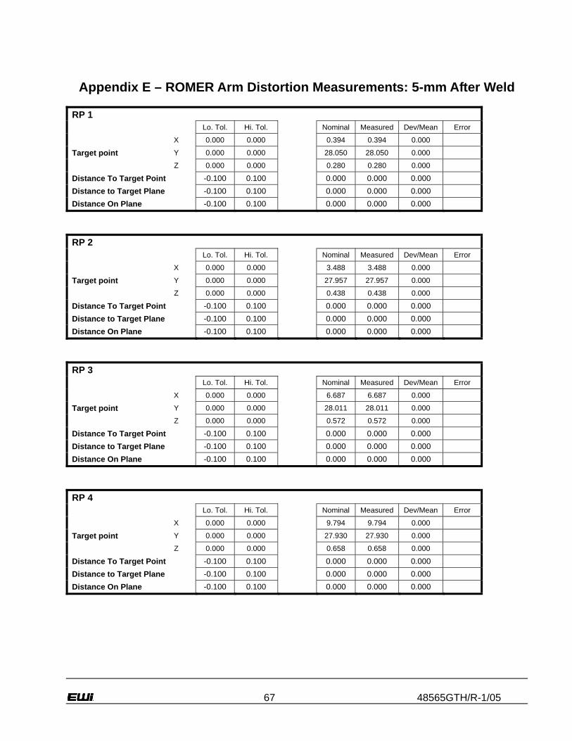
67 48565GTH/R-1/05
Appendix E – ROMER Arm Distortion Measurements: 5-mm After Weld
RP 1 Lo. Tol. Hi. Tol. Nominal Measured Dev/Mean Error
X 0.000 0.000 0.394 0.394 0.000
Target point Y 0.000 0.000 28.050 28.050 0.000
Z 0.000 0.000 0.280 0.280 0.000
Distance To Target Point -0.100 0.100 0.000 0.000 0.000 Distance to Target Plane -0.100 0.100 0.000 0.000 0.000 Distance On Plane -0.100 0.100 0.000 0.000 0.000
RP 2 Lo. Tol. Hi. Tol. Nominal Measured Dev/Mean Error
X 0.000 0.000 3.488 3.488 0.000
Target point Y 0.000 0.000 27.957 27.957 0.000
Z 0.000 0.000 0.438 0.438 0.000
Distance To Target Point -0.100 0.100 0.000 0.000 0.000 Distance to Target Plane -0.100 0.100 0.000 0.000 0.000 Distance On Plane -0.100 0.100 0.000 0.000 0.000
RP 3 Lo. Tol. Hi. Tol. Nominal Measured Dev/Mean Error
X 0.000 0.000 6.687 6.687 0.000
Target point Y 0.000 0.000 28.011 28.011 0.000
Z 0.000 0.000 0.572 0.572 0.000
Distance To Target Point -0.100 0.100 0.000 0.000 0.000 Distance to Target Plane -0.100 0.100 0.000 0.000 0.000 Distance On Plane -0.100 0.100 0.000 0.000 0.000
RP 4 Lo. Tol. Hi. Tol. Nominal Measured Dev/Mean Error
X 0.000 0.000 9.794 9.794 0.000
Target point Y 0.000 0.000 27.930 27.930 0.000
Z 0.000 0.000 0.658 0.658 0.000
Distance To Target Point -0.100 0.100 0.000 0.000 0.000 Distance to Target Plane -0.100 0.100 0.000 0.000 0.000 Distance On Plane -0.100 0.100 0.000 0.000 0.000

68 48565GTH/R-1/05
RP 5 Lo. Tol. Hi. Tol. Nominal Measured Dev/Mean Error
X 0.000 0.000 12.839 12.839 0.000
Target point Y 0.000 0.000 27.999 27.999 0.000
Z 0.000 0.000 0.680 0.680 0.000
Distance To Target Point -0.100 0.100 0.000 0.000 0.000 Distance to Target Plane -0.100 0.100 0.000 0.000 0.000 Distance On Plane -0.100 0.100 0.000 0.000 0.000
RP 6 Lo. Tol. Hi. Tol. Nominal Measured Dev/Mean Error
X 0.000 0.000 16.044 16.044 0.000
Target point Y 0.000 0.000 27.871 27.871 0.000
Z 0.000 0.000 0.635 0.635 0.000
Distance To Target Point -0.100 0.100 0.000 0.000 0.000 Distance to Target Plane -0.100 0.100 0.000 0.000 0.000 Distance On Plane -0.100 0.100 0.000 0.000 0.000
RP 7 Lo. Tol. Hi. Tol. Nominal Measured Dev/Mean Error
X 0.000 0.000 19.222 19.222 0.000
Target point Y 0.000 0.000 27.949 27.949 0.000
Z 0.000 0.000 0.543 0.543 0.000
Distance To Target Point -0.100 0.100 0.000 0.000 0.000 Distance to Target Plane -0.100 0.100 0.000 0.000 0.000 Distance On Plane -0.100 0.100 0.000 0.000 0.000
RP 8 Lo. Tol. Hi. Tol. Nominal Measured Dev/Mean Error
X 0.000 0.000 22.353 22.353 0.000
Target point Y 0.000 0.000 27.971 27.971 0.000
Z 0.000 0.000 0.422 0.422 0.000
Distance To Target Point -0.100 0.100 0.000 0.000 0.000 Distance to Target Plane -0.100 0.100 0.000 0.000 0.000 Distance On Plane -0.100 0.100 0.000 0.000 0.000

69 48565GTH/R-1/05
RP 9 Lo. Tol. Hi. Tol. Nominal Measured Dev/Mean Error
X 0.000 0.000 22.277 22.277 0.000
Target point Y 0.000 0.000 24.187 24.187 0.000
Z 0.000 0.000 0.359 0.359 0.000
Distance To Target Point -0.100 0.100 0.000 0.000 0.000 Distance to Target Plane -0.100 0.100 0.000 0.000 0.000 Distance On Plane -0.100 0.100 0.000 0.000 0.000
RP 10 Lo. Tol. Hi. Tol. Nominal Measured Dev/Mean Error
X 0.000 0.000 19.141 19.141 0.000
Target point Y 0.000 0.000 24.167 24.167 0.000
Z 0.000 0.000 0.471 0.471 0.000
Distance To Target Point -0.100 0.100 0.000 0.000 0.000 Distance to Target Plane -0.100 0.100 0.000 0.000 0.000 Distance On Plane -0.100 0.100 0.000 0.000 0.000
RP 11 Lo. Tol. Hi. Tol. Nominal Measured Dev/Mean Error
X 0.000 0.000 16.091 16.091 0.000
Target point Y 0.000 0.000 24.227 24.227 0.000
Z 0.000 0.000 0.549 0.549 0.000
Distance To Target Point -0.100 0.100 0.000 0.000 0.000 Distance to Target Plane -0.100 0.100 0.000 0.000 0.000 Distance On Plane -0.100 0.100 0.000 0.000 0.000
RP 12 Lo. Tol. Hi. Tol. Nominal Measured Dev/Mean Error
X 0.000 0.000 12.873 12.873 0.000
Target point Y 0.000 0.000 24.223 24.223 0.000
Z 0.000 0.000 0.586 0.586 0.000
Distance To Target Point -0.100 0.100 0.000 0.000 0.000 Distance to Target Plane -0.100 0.100 0.000 0.000 0.000 Distance On Plane -0.100 0.100 0.000 0.000 0.000

70 48565GTH/R-1/05
RP 13 Lo. Tol. Hi. Tol. Nominal Measured Dev/Mean Error
X 0.000 0.000 9.787 9.787 0.000
Target point Y 0.000 0.000 24.314 24.314 0.000
Z 0.000 0.000 0.573 0.573 0.000
Distance To Target Point -0.100 0.100 0.000 0.000 0.000 Distance to Target Plane -0.100 0.100 0.000 0.000 0.000 Distance On Plane -0.100 0.100 0.000 0.000 0.000
RP 14 Lo. Tol. Hi. Tol. Nominal Measured Dev/Mean Error
X 0.000 0.000 6.493 6.493 0.000
Target point Y 0.000 0.000 24.352 24.352 0.000
Z 0.000 0.000 0.502 0.502 0.000
Distance To Target Point -0.100 0.100 0.000 0.000 0.000 Distance to Target Plane -0.100 0.100 0.000 0.000 0.000 Distance On Plane -0.100 0.100 0.000 0.000 0.000
RP 15 Lo. Tol. Hi. Tol. Nominal Measured Dev/Mean Error
X 0.000 0.000 3.508 3.508 0.000
Target point Y 0.000 0.000 24.343 24.343 0.000
Z 0.000 0.000 0.395 0.395 0.000
Distance To Target Point -0.100 0.100 0.000 0.000 0.000 Distance to Target Plane -0.100 0.100 0.000 0.000 0.000 Distance On Plane -0.100 0.100 0.000 0.000 0.000
RP 16 Lo. Tol. Hi. Tol. Nominal Measured Dev/Mean Error
X 0.000 0.000 0.345 0.345 0.000
Target point Y 0.000 0.000 24.378 24.378 0.000
Z 0.000 0.000 0.239 0.239 0.000
Distance To Target Point -0.100 0.100 0.000 0.000 0.000 Distance to Target Plane -0.100 0.100 0.000 0.000 0.000 Distance On Plane -0.100 0.100 0.000 0.000 0.000

71 48565GTH/R-1/05
RP 17 Lo. Tol. Hi. Tol. Nominal Measured Dev/Mean Error
X 0.000 0.000 0.312 0.312 0.000
Target point Y 0.000 0.000 22.221 22.221 0.000
Z 0.000 0.000 0.239 0.239 0.000
Distance To Target Point -0.100 0.100 0.000 0.000 0.000 Distance to Target Plane -0.100 0.100 0.000 0.000 0.000 Distance On Plane -0.100 0.100 0.000 0.000 0.000
RP 18 Lo. Tol. Hi. Tol. Nominal Measured Dev/Mean Error
X 0.000 0.000 3.393 3.393 0.000
Target point Y 0.000 0.000 22.137 22.137 0.000
Z 0.000 0.000 0.383 0.383 0.000
Distance To Target Point -0.100 0.100 0.000 0.000 0.000 Distance to Target Plane -0.100 0.100 0.000 0.000 0.000 Distance On Plane -0.100 0.100 0.000 0.000 0.000
RP 19 Lo. Tol. Hi. Tol. Nominal Measured Dev/Mean Error
X 0.000 0.000 6.594 6.594 0.000
Target point Y 0.000 0.000 22.212 22.212 0.000
Z 0.000 0.000 0.495 0.495 0.000
Distance To Target Point -0.100 0.100 0.000 0.000 0.000 Distance to Target Plane -0.100 0.100 0.000 0.000 0.000 Distance On Plane -0.100 0.100 0.000 0.000 0.000
RP 20 Lo. Tol. Hi. Tol. Nominal Measured Dev/Mean Error
X 0.000 0.000 9.607 9.607 0.000
Target point Y 0.000 0.000 22.129 22.129 0.000
Z 0.000 0.000 0.557 0.557 0.000
Distance To Target Point -0.100 0.100 0.000 0.000 0.000 Distance to Target Plane -0.100 0.100 0.000 0.000 0.000 Distance On Plane -0.100 0.100 0.000 0.000 0.000

72 48565GTH/R-1/05
RP 21 Lo. Tol. Hi. Tol. Nominal Measured Dev/Mean Error
X 0.000 0.000 12.874 12.874 0.000
Target point Y 0.000 0.000 22.004 22.004 0.000
Z 0.000 0.000 0.564 0.564 0.000
Distance To Target Point -0.100 0.100 0.000 0.000 0.000 Distance to Target Plane -0.100 0.100 0.000 0.000 0.000 Distance On Plane -0.100 0.100 0.000 0.000 0.000
RP 22 Lo. Tol. Hi. Tol. Nominal Measured Dev/Mean Error
X 0.000 0.000 16.051 16.051 0.000
Target point Y 0.000 0.000 22.095 22.095 0.000
Z 0.000 0.000 0.525 0.525 0.000
Distance To Target Point -0.100 0.100 0.000 0.000 0.000 Distance to Target Plane -0.100 0.100 0.000 0.000 0.000 Distance On Plane -0.100 0.100 0.000 0.000 0.000
RP 23 Lo. Tol. Hi. Tol. Nominal Measured Dev/Mean Error
X 0.000 0.000 19.172 19.172 0.000
Target point Y 0.000 0.000 22.032 22.032 0.000
Z 0.000 0.000 0.446 0.446 0.000
Distance To Target Point -0.100 0.100 0.000 0.000 0.000 Distance to Target Plane -0.100 0.100 0.000 0.000 0.000 Distance On Plane -0.100 0.100 0.000 0.000 0.000
RP 24 Lo. Tol. Hi. Tol. Nominal Measured Dev/Mean Error
X 0.000 0.000 22.294 22.294 0.000
Target point Y 0.000 0.000 22.010 22.010 0.000
Z 0.000 0.000 0.335 0.335 0.000
Distance To Target Point -0.100 0.100 0.000 0.000 0.000 Distance to Target Plane -0.100 0.100 0.000 0.000 0.000 Distance On Plane -0.100 0.100 0.000 0.000 0.000

73 48565GTH/R-1/05
RP 25 Lo. Tol. Hi. Tol. Nominal Measured Dev/Mean Error
X 0.000 0.000 22.290 22.290 0.000
Target point Y 0.000 0.000 18.297 18.297 0.000
Z 0.000 0.000 0.313 0.313 0.000
Distance To Target Point -0.100 0.100 0.000 0.000 0.000 Distance to Target Plane -0.100 0.100 0.000 0.000 0.000 Distance On Plane -0.100 0.100 0.000 0.000 0.000
RP 26 Lo. Tol. Hi. Tol. Nominal Measured Dev/Mean Error
X 0.000 0.000 19.149 19.149 0.000
Target point Y 0.000 0.000 18.254 18.254 0.000
Z 0.000 0.000 0.429 0.429 0.000
Distance To Target Point -0.100 0.100 0.000 0.000 0.000 Distance to Target Plane -0.100 0.100 0.000 0.000 0.000 Distance On Plane -0.100 0.100 0.000 0.000 0.000
RP 27 Lo. Tol. Hi. Tol. Nominal Measured Dev/Mean Error
X 0.000 0.000 16.049 16.049 0.000
Target point Y 0.000 0.000 18.321 18.321 0.000
Z 0.000 0.000 0.519 0.519 0.000
Distance To Target Point -0.100 0.100 0.000 0.000 0.000 Distance to Target Plane -0.100 0.100 0.000 0.000 0.000 Distance On Plane -0.100 0.100 0.000 0.000 0.000
RP 28 Lo. Tol. Hi. Tol. Nominal Measured Dev/Mean Error
X 0.000 0.000 12.755 12.755 0.000
Target point Y 0.000 0.000 18.332 18.332 0.000
Z 0.000 0.000 0.577 0.577 0.000
Distance To Target Point -0.100 0.100 0.000 0.000 0.000 Distance to Target Plane -0.100 0.100 0.000 0.000 0.000 Distance On Plane -0.100 0.100 0.000 0.000 0.000

74 48565GTH/R-1/05
RP 29 Lo. Tol. Hi. Tol. Nominal Measured Dev/Mean Error
X 0.000 0.000 9.659 9.659 0.000
Target point Y 0.000 0.000 18.354 18.354 0.000
Z 0.000 0.000 0.583 0.583 0.000
Distance To Target Point -0.100 0.100 0.000 0.000 0.000 Distance to Target Plane -0.100 0.100 0.000 0.000 0.000 Distance On Plane -0.100 0.100 0.000 0.000 0.000
RP 30 Lo. Tol. Hi. Tol. Nominal Measured Dev/Mean Error
X 0.000 0.000 6.618 6.618 0.000
Target point Y 0.000 0.000 18.419 18.419 0.000
Z 0.000 0.000 0.524 0.524 0.000
Distance To Target Point -0.100 0.100 0.000 0.000 0.000 Distance to Target Plane -0.100 0.100 0.000 0.000 0.000 Distance On Plane -0.100 0.100 0.000 0.000 0.000
RP 31 Lo. Tol. Hi. Tol. Nominal Measured Dev/Mean Error
X 0.000 0.000 3.398 3.398 0.000
Target point Y 0.000 0.000 18.374 18.374 0.000
Z 0.000 0.000 0.411 0.411 0.000
Distance To Target Point -0.100 0.100 0.000 0.000 0.000 Distance to Target Plane -0.100 0.100 0.000 0.000 0.000 Distance On Plane -0.100 0.100 0.000 0.000 0.000
RP 32 Lo. Tol. Hi. Tol. Nominal Measured Dev/Mean Error
X 0.000 0.000 0.357 0.357 0.000
Target point Y 0.000 0.000 18.388 18.388 0.000
Z 0.000 0.000 0.270 0.270 0.000
Distance To Target Point -0.100 0.100 0.000 0.000 0.000 Distance to Target Plane -0.100 0.100 0.000 0.000 0.000 Distance On Plane -0.100 0.100 0.000 0.000 0.000

75 48565GTH/R-1/05
Appendix F – ROMER Arm Distortion Measurements: 8-mm Before Weld
RP 1 Lo. Tol. Hi. Tol. Nominal Measured Dev/Mean Error
X 0.000 0.000 3.618 3.618 0.000
Target point Y 0.000 0.000 28.727 28.727 0.000
Z 0.000 0.000 0.349 0.349 0.000
Distance To Target Point -0.100 0.100 0.000 0.000 0.000 Distance to Target Plane -0.100 0.100 0.000 0.000 0.000 Distance On Plane -0.100 0.100 0.000 0.000 0.000
RP 2 Lo. Tol. Hi. Tol. Nominal Measured Dev/Mean Error
X 0.000 0.000 6.754 6.754 0.000
Target point Y 0.000 0.000 28.636 28.636 0.000
Z 0.000 0.000 0.361 0.361 0.000
Distance To Target Point -0.100 0.100 0.000 0.000 0.000 Distance to Target Plane -0.100 0.100 0.000 0.000 0.000 Distance On Plane -0.100 0.100 0.000 0.000 0.000
RP 3 Lo. Tol. Hi. Tol. Nominal Measured Dev/Mean Error
X 0.000 0.000 9.940 9.940 0.000
Target point Y 0.000 0.000 28.618 28.618 0.000
Z 0.000 0.000 0.370 0.370 0.000
Distance To Target Point -0.100 0.100 0.000 0.000 0.000 Distance to Target Plane -0.100 0.100 0.000 0.000 0.000 Distance On Plane -0.100 0.100 0.000 0.000 0.000
RP 4 Lo. Tol. Hi. Tol. Nominal Measured Dev/Mean Error
X 0.000 0.000 13.103 13.103 0.000
Target point Y 0.000 0.000 28.594 28.594 0.000
Z 0.000 0.000 0.371 0.371 0.000
Distance To Target Point -0.100 0.100 0.000 0.000 0.000 Distance to Target Plane -0.100 0.100 0.000 0.000 0.000 Distance On Plane -0.100 0.100 0.000 0.000 0.000

76 48565GTH/R-1/05
RP 5 Lo. Tol. Hi. Tol. Nominal Measured Dev/Mean Error
X 0.000 0.000 16.151 16.151 0.000
Target point Y 0.000 0.000 28.599 28.599 0.000
Z 0.000 0.000 0.367 0.367 0.000
Distance To Target Point -0.100 0.100 0.000 0.000 0.000 Distance to Target Plane -0.100 0.100 0.000 0.000 0.000 Distance On Plane -0.100 0.100 0.000 0.000 0.000
RP 6 Lo. Tol. Hi. Tol. Nominal Measured Dev/Mean Error
X 0.000 0.000 19.362 19.362 0.000
Target point Y 0.000 0.000 28.495 28.495 0.000
Z 0.000 0.000 0.357 0.357 0.000
Distance To Target Point -0.100 0.100 0.000 0.000 0.000 Distance to Target Plane -0.100 0.100 0.000 0.000 0.000 Distance On Plane -0.100 0.100 0.000 0.000 0.000
RP 7 Lo. Tol. Hi. Tol. Nominal Measured Dev/Mean Error
X 0.000 0.000 22.451 22.451 0.000
Target point Y 0.000 0.000 28.452 28.452 0.000
Z 0.000 0.000 0.349 0.349 0.000
Distance To Target Point -0.100 0.100 0.000 0.000 0.000 Distance to Target Plane -0.100 0.100 0.000 0.000 0.000 Distance On Plane -0.100 0.100 0.000 0.000 0.000
RP 8 Lo. Tol. Hi. Tol. Nominal Measured Dev/Mean Error
X 0.000 0.000 25.561 25.561 0.000
Target point Y 0.000 0.000 28.406 28.406 0.000
Z 0.000 0.000 0.338 0.338 0.000
Distance To Target Point -0.100 0.100 0.000 0.000 0.000 Distance to Target Plane -0.100 0.100 0.000 0.000 0.000 Distance On Plane -0.100 0.100 0.000 0.000 0.000

77 48565GTH/R-1/05
RP 9 Lo. Tol. Hi. Tol. Nominal Measured Dev/Mean Error
X 0.000 0.000 25.511 25.511 0.000
Target point Y 0.000 0.000 24.739 24.739 0.000
Z 0.000 0.000 0.356 0.356 0.000
Distance To Target Point -0.100 0.100 0.000 0.000 0.000 Distance to Target Plane -0.100 0.100 0.000 0.000 0.000 Distance On Plane -0.100 0.100 0.000 0.000 0.000
RP 10 Lo. Tol. Hi. Tol. Nominal Measured Dev/Mean Error
X 0.000 0.000 22.354 22.354 0.000
Target point Y 0.000 0.000 24.744 24.744 0.000
Z 0.000 0.000 0.363 0.363 0.000
Distance To Target Point -0.100 0.100 0.000 0.000 0.000 Distance to Target Plane -0.100 0.100 0.000 0.000 0.000 Distance On Plane -0.100 0.100 0.000 0.000 0.000
RP 11 Lo. Tol. Hi. Tol. Nominal Measured Dev/Mean Error
X 0.000 0.000 19.226 19.226 0.000
Target point Y 0.000 0.000 24.825 24.825 0.000
Z 0.000 0.000 0.369 0.369 0.000
Distance To Target Point -0.100 0.100 0.000 0.000 0.000 Distance to Target Plane -0.100 0.100 0.000 0.000 0.000 Distance On Plane -0.100 0.100 0.000 0.000 0.000
RP 12 Lo. Tol. Hi. Tol. Nominal Measured Dev/Mean Error
X 0.000 0.000 16.041 16.041 0.000
Target point Y 0.000 0.000 24.890 24.890 0.000
Z 0.000 0.000 0.374 0.374 0.000
Distance To Target Point -0.100 0.100 0.000 0.000 0.000 Distance to Target Plane -0.100 0.100 0.000 0.000 0.000 Distance On Plane -0.100 0.100 0.000 0.000 0.000

78 48565GTH/R-1/05
RP 13 Lo. Tol. Hi. Tol. Nominal Measured Dev/Mean Error
X 0.000 0.000 12.945 12.945 0.000
Target point Y 0.000 0.000 24.941 24.941 0.000
Z 0.000 0.000 0.371 0.371 0.000
Distance To Target Point -0.100 0.100 0.000 0.000 0.000 Distance to Target Plane -0.100 0.100 0.000 0.000 0.000 Distance On Plane -0.100 0.100 0.000 0.000 0.000
RP 14 Lo. Tol. Hi. Tol. Nominal Measured Dev/Mean Error
X 0.000 0.000 9.821 9.821 0.000
Target point Y 0.000 0.000 24.971 24.971 0.000
Z 0.000 0.000 0.365 0.365 0.000
Distance To Target Point -0.100 0.100 0.000 0.000 0.000 Distance to Target Plane -0.100 0.100 0.000 0.000 0.000 Distance On Plane -0.100 0.100 0.000 0.000 0.000
RP 15 Lo. Tol. Hi. Tol. Nominal Measured Dev/Mean Error
X 0.000 0.000 6.721 6.721 0.000
Target point Y 0.000 0.000 25.054 25.054 0.000
Z 0.000 0.000 0.354 0.354 0.000
Distance To Target Point -0.100 0.100 0.000 0.000 0.000 Distance to Target Plane -0.100 0.100 0.000 0.000 0.000 Distance On Plane -0.100 0.100 0.000 0.000 0.000
RP 16 Lo. Tol. Hi. Tol. Nominal Measured Dev/Mean Error
X 0.000 0.000 3.552 3.552 0.000
Target point Y 0.000 0.000 25.108 25.108 0.000
Z 0.000 0.000 0.340 0.340 0.000
Distance To Target Point -0.100 0.100 0.000 0.000 0.000 Distance to Target Plane -0.100 0.100 0.000 0.000 0.000 Distance On Plane -0.100 0.100 0.000 0.000 0.000

79 48565GTH/R-1/05
RP 17 Lo. Tol. Hi. Tol. Nominal Measured Dev/Mean Error
X 0.000 0.000 3.442 3.442 0.000
Target point Y 0.000 0.000 22.925 22.925 0.000
Z 0.000 0.000 0.332 0.332 0.000
Distance To Target Point -0.100 0.100 0.000 0.000 0.000 Distance to Target Plane -0.100 0.100 0.000 0.000 0.000 Distance On Plane -0.100 0.100 0.000 0.000 0.000
RP 18 Lo. Tol. Hi. Tol. Nominal Measured Dev/Mean Error
X 0.000 0.000 6.606 6.606 0.000
Target point Y 0.000 0.000 22.863 22.863 0.000
Z 0.000 0.000 0.344 0.344 0.000
Distance To Target Point -0.100 0.100 0.000 0.000 0.000 Distance to Target Plane -0.100 0.100 0.000 0.000 0.000 Distance On Plane -0.100 0.100 0.000 0.000 0.000
RP 19 Lo. Tol. Hi. Tol. Nominal Measured Dev/Mean Error
X 0.000 0.000 9.807 9.807 0.000
Target point Y 0.000 0.000 22.798 22.798 0.000
Z 0.000 0.000 0.357 0.357 0.000
Distance To Target Point -0.100 0.100 0.000 0.000 0.000 Distance to Target Plane -0.100 0.100 0.000 0.000 0.000 Distance On Plane -0.100 0.100 0.000 0.000 0.000
RP 20 Lo. Tol. Hi. Tol. Nominal Measured Dev/Mean Error
X 0.000 0.000 12.894 12.894 0.000
Target point Y 0.000 0.000 22.700 22.700 0.000
Z 0.000 0.000 0.364 0.364 0.000
Distance To Target Point -0.100 0.100 0.000 0.000 0.000 Distance to Target Plane -0.100 0.100 0.000 0.000 0.000 Distance On Plane -0.100 0.100 0.000 0.000 0.000

80 48565GTH/R-1/05
RP 21 Lo. Tol. Hi. Tol. Nominal Measured Dev/Mean Error
X 0.000 0.000 16.037 16.037 0.000
Target point Y 0.000 0.000 22.668 22.668 0.000
Z 0.000 0.000 0.368 0.368 0.000
Distance To Target Point -0.100 0.100 0.000 0.000 0.000 Distance to Target Plane -0.100 0.100 0.000 0.000 0.000 Distance On Plane -0.100 0.100 0.000 0.000 0.000
RP 22 Lo. Tol. Hi. Tol. Nominal Measured Dev/Mean Error
X 0.000 0.000 19.230 19.230 0.000
Target point Y 0.000 0.000 22.601 22.601 0.000
Z 0.000 0.000 0.363 0.363 0.000
Distance To Target Point -0.100 0.100 0.000 0.000 0.000 Distance to Target Plane -0.100 0.100 0.000 0.000 0.000 Distance On Plane -0.100 0.100 0.000 0.000 0.000
RP 23 Lo. Tol. Hi. Tol. Nominal Measured Dev/Mean Error
X 0.000 0.000 22.277 22.277 0.000
Target point Y 0.000 0.000 22.543 22.543 0.000
Z 0.000 0.000 0.357 0.357 0.000
Distance To Target Point -0.100 0.100 0.000 0.000 0.000 Distance to Target Plane -0.100 0.100 0.000 0.000 0.000 Distance On Plane -0.100 0.100 0.000 0.000 0.000
RP 24 Lo. Tol. Hi. Tol. Nominal Measured Dev/Mean Error
X 0.000 0.000 25.516 25.516 0.000
Target point Y 0.000 0.000 22.511 22.511 0.000
Z 0.000 0.000 0.346 0.346 0.000
Distance To Target Point -0.100 0.100 0.000 0.000 0.000 Distance to Target Plane -0.100 0.100 0.000 0.000 0.000 Distance On Plane -0.100 0.100 0.000 0.000 0.000

81 48565GTH/R-1/05
RP 25 Lo. Tol. Hi. Tol. Nominal Measured Dev/Mean Error
X 0.000 0.000 25.416 25.416 0.000
Target point Y 0.000 0.000 18.733 18.733 0.000
Z 0.000 0.000 0.346 0.346 0.000
Distance To Target Point -0.100 0.100 0.000 0.000 0.000 Distance to Target Plane -0.100 0.100 0.000 0.000 0.000 Distance On Plane -0.100 0.100 0.000 0.000 0.000
RP 26 Lo. Tol. Hi. Tol. Nominal Measured Dev/Mean Error
X 0.000 0.000 22.265 22.265 0.000
Target point Y 0.000 0.000 18.811 18.811 0.000
Z 0.000 0.000 0.355 0.355 0.000
Distance To Target Point -0.100 0.100 0.000 0.000 0.000 Distance to Target Plane -0.100 0.100 0.000 0.000 0.000 Distance On Plane -0.100 0.100 0.000 0.000 0.000
RP 27 Lo. Tol. Hi. Tol. Nominal Measured Dev/Mean Error
X 0.000 0.000 19.243 19.243 0.000
Target point Y 0.000 0.000 18.836 18.836 0.000
Z 0.000 0.000 0.363 0.363 0.000
Distance To Target Point -0.100 0.100 0.000 0.000 0.000 Distance to Target Plane -0.100 0.100 0.000 0.000 0.000 Distance On Plane -0.100 0.100 0.000 0.000 0.000
RP 28 Lo. Tol. Hi. Tol. Nominal Measured Dev/Mean Error
X 0.000 0.000 15.973 15.973 0.000
Target point Y 0.000 0.000 18.948 18.948 0.000
Z 0.000 0.000 0.361 0.361 0.000
Distance To Target Point -0.100 0.100 0.000 0.000 0.000 Distance to Target Plane -0.100 0.100 0.000 0.000 0.000 Distance On Plane -0.100 0.100 0.000 0.000 0.000

82 48565GTH/R-1/05
RP 29 Lo. Tol. Hi. Tol. Nominal Measured Dev/Mean Error
X 0.000 0.000 12.835 12.835 0.000
Target point Y 0.000 0.000 18.909 18.909 0.000
Z 0.000 0.000 0.355 0.355 0.000
Distance To Target Point -0.100 0.100 0.000 0.000 0.000 Distance to Target Plane -0.100 0.100 0.000 0.000 0.000 Distance On Plane -0.100 0.100 0.000 0.000 0.000
RP 30 Lo. Tol. Hi. Tol. Nominal Measured Dev/Mean Error
X 0.000 0.000 9.743 9.743 0.000
Target point Y 0.000 0.000 18.978 18.978 0.000
Z 0.000 0.000 0.342 0.342 0.000
Distance To Target Point -0.100 0.100 0.000 0.000 0.000 Distance to Target Plane -0.100 0.100 0.000 0.000 0.000 Distance On Plane -0.100 0.100 0.000 0.000 0.000
RP 31 Lo. Tol. Hi. Tol. Nominal Measured Dev/Mean Error
X 0.000 0.000 6.525 6.525 0.000
Target point Y 0.000 0.000 19.108 19.108 0.000
Z 0.000 0.000 0.325 0.325 0.000
Distance To Target Point -0.100 0.100 0.000 0.000 0.000 Distance to Target Plane -0.100 0.100 0.000 0.000 0.000 Distance On Plane -0.100 0.100 0.000 0.000 0.000
RP 32 Lo. Tol. Hi. Tol. Nominal Measured Dev/Mean Error
X 0.000 0.000 3.470 3.470 0.000
Target point Y 0.000 0.000 19.106 19.106 0.000
Z 0.000 0.000 0.311 0.311 0.000
Distance To Target Point -0.100 0.100 0.000 0.000 0.000 Distance to Target Plane -0.100 0.100 0.000 0.000 0.000 Distance On Plane -0.100 0.100 0.000 0.000 0.000

83 48565GTH/R-1/05
Appendix G – ROMER Arm Distortion Measurements: 8-mm After Weld
RP 1 Lo. Tol. Hi. Tol. Nominal Measured Dev/Mean Error
X 0.000 0.000 2.173 2.173 0.000
Target point Y 0.000 0.000 25.700 25.700 0.000
Z 0.000 0.000 0.383 0.383 0.000
Distance To Target Point -0.100 0.100 0.000 0.000 0.000 Distance to Target Plane -0.100 0.100 0.000 0.000 0.000 Distance On Plane -0.100 0.100 0.000 0.000 0.000
RP 2 Lo. Tol. Hi. Tol. Nominal Measured Dev/Mean Error
X 0.000 0.000 5.339 5.339 0.000
Target point Y 0.000 0.000 25.738 25.738 0.000
Z 0.000 0.000 0.405 0.405 0.000
Distance To Target Point -0.100 0.100 0.000 0.000 0.000 Distance to Target Plane -0.100 0.100 0.000 0.000 0.000 Distance On Plane -0.100 0.100 0.000 0.000 0.000
RP 3 Lo. Tol. Hi. Tol. Nominal Measured Dev/Mean Error
X 0.000 0.000 8.454 8.454 0.000
Target point Y 0.000 0.000 25.755 25.755 0.000
Z 0.000 0.000 0.420 0.420 0.000
Distance To Target Point -0.100 0.100 0.000 0.000 0.000 Distance to Target Plane -0.100 0.100 0.000 0.000 0.000 Distance On Plane -0.100 0.100 0.000 0.000 0.000
RP 4 Lo. Tol. Hi. Tol. Nominal Measured Dev/Mean Error
X 0.000 0.000 11.576 11.576 0.000
Target point Y 0.000 0.000 25.681 25.681 0.000
Z 0.000 0.000 0.423 0.423 0.000
Distance To Target Point -0.100 0.100 0.000 0.000 0.000 Distance to Target Plane -0.100 0.100 0.000 0.000 0.000 Distance On Plane -0.100 0.100 0.000 0.000 0.000

84 48565GTH/R-1/05
RP 5 Lo. Tol. Hi. Tol. Nominal Measured Dev/Mean Error
X 0.000 0.000 14.638 14.638 0.000
Target point Y 0.000 0.000 25.677 25.677 0.000
Z 0.000 0.000 0.414 0.414 0.000
Distance To Target Point -0.100 0.100 0.000 0.000 0.000 Distance to Target Plane -0.100 0.100 0.000 0.000 0.000 Distance On Plane -0.100 0.100 0.000 0.000 0.000
RP 6 Lo. Tol. Hi. Tol. Nominal Measured Dev/Mean Error
X 0.000 0.000 17.849 17.849 0.000
Target point Y 0.000 0.000 25.735 25.735 0.000
Z 0.000 0.000 0.396 0.396 0.000
Distance To Target Point -0.100 0.100 0.000 0.000 0.000 Distance to Target Plane -0.100 0.100 0.000 0.000 0.000 Distance On Plane -0.100 0.100 0.000 0.000 0.000
RP 7 Lo. Tol. Hi. Tol. Nominal Measured Dev/Mean Error
X 0.000 0.000 20.883 20.883 0.000
Target point Y 0.000 0.000 25.675 25.675 0.000
Z 0.000 0.000 0.384 0.384 0.000
Distance To Target Point -0.100 0.100 0.000 0.000 0.000 Distance to Target Plane -0.100 0.100 0.000 0.000 0.000 Distance On Plane -0.100 0.100 0.000 0.000 0.000
RP 8 Lo. Tol. Hi. Tol. Nominal Measured Dev/Mean Error
X 0.000 0.000 24.106 24.106 0.000
Target point Y 0.000 0.000 25.666 25.666 0.000
Z 0.000 0.000 0.367 0.367 0.000
Distance To Target Point -0.100 0.100 0.000 0.000 0.000 Distance to Target Plane -0.100 0.100 0.000 0.000 0.000 Distance On Plane -0.100 0.100 0.000 0.000 0.000

85 48565GTH/R-1/05
RP 9 Lo. Tol. Hi. Tol. Nominal Measured Dev/Mean Error
X 0.000 0.000 24.104 24.104 0.000
Target point Y 0.000 0.000 21.977 21.977 0.000
Z 0.000 0.000 0.402 0.402 0.000
Distance To Target Point -0.100 0.100 0.000 0.000 0.000 Distance to Target Plane -0.100 0.100 0.000 0.000 0.000 Distance On Plane -0.100 0.100 0.000 0.000 0.000
RP 10 Lo. Tol. Hi. Tol. Nominal Measured Dev/Mean Error
X 0.000 0.000 20.892 20.892 0.000
Target point Y 0.000 0.000 21.936 21.936 0.000
Z 0.000 0.000 0.407 0.407 0.000
Distance To Target Point -0.100 0.100 0.000 0.000 0.000 Distance to Target Plane -0.100 0.100 0.000 0.000 0.000 Distance On Plane -0.100 0.100 0.000 0.000 0.000
RP 11 Lo. Tol. Hi. Tol. Nominal Measured Dev/Mean Error
X 0.000 0.000 17.868 17.868 0.000
Target point Y 0.000 0.000 21.984 21.984 0.000
Z 0.000 0.000 0.416 0.416 0.000
Distance To Target Point -0.100 0.100 0.000 0.000 0.000 Distance to Target Plane -0.100 0.100 0.000 0.000 0.000 Distance On Plane -0.100 0.100 0.000 0.000 0.000
RP 12 Lo. Tol. Hi. Tol. Nominal Measured Dev/Mean Error
X 0.000 0.000 14.647 14.647 0.000
Target point Y 0.000 0.000 22.089 22.089 0.000
Z 0.000 0.000 0.421 0.421 0.000
Distance To Target Point -0.100 0.100 0.000 0.000 0.000 Distance to Target Plane -0.100 0.100 0.000 0.000 0.000 Distance On Plane -0.100 0.100 0.000 0.000 0.000
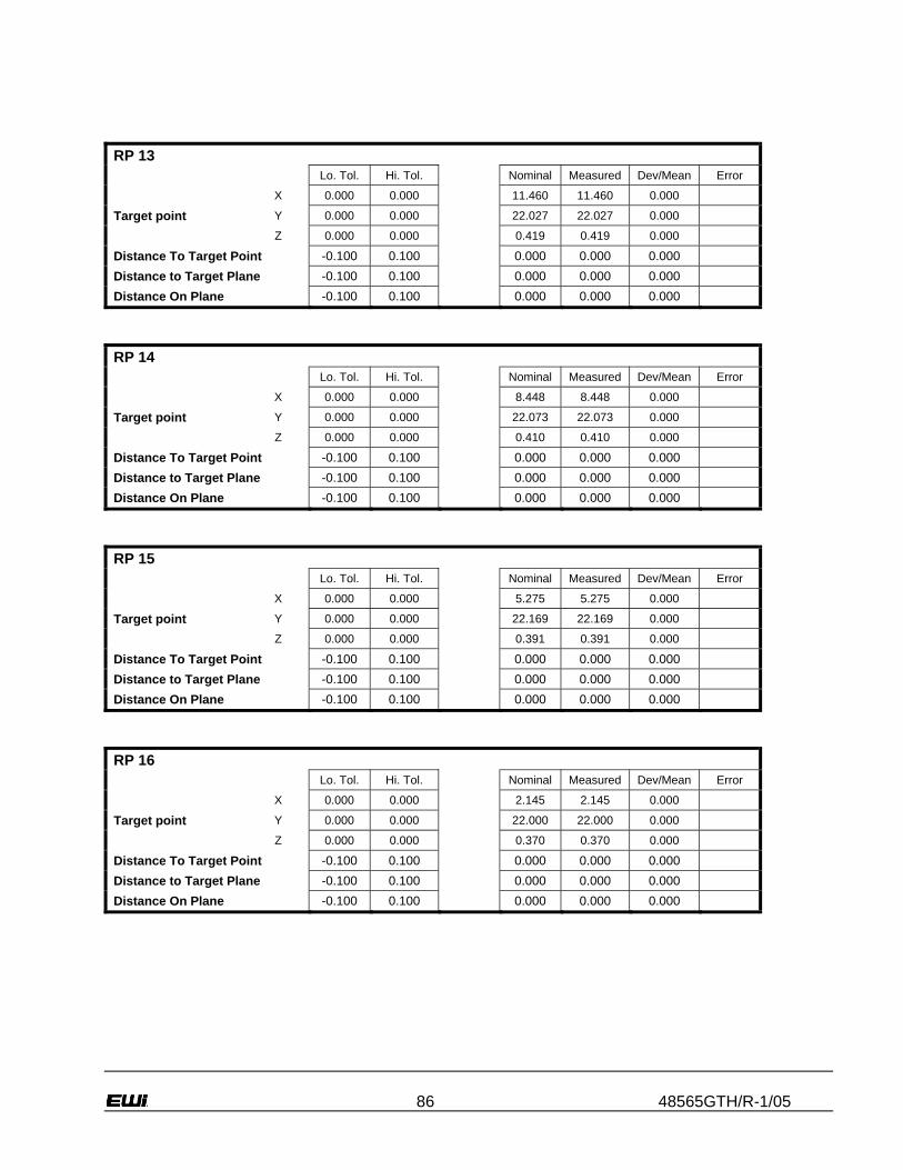
86 48565GTH/R-1/05
RP 13 Lo. Tol. Hi. Tol. Nominal Measured Dev/Mean Error
X 0.000 0.000 11.460 11.460 0.000
Target point Y 0.000 0.000 22.027 22.027 0.000
Z 0.000 0.000 0.419 0.419 0.000
Distance To Target Point -0.100 0.100 0.000 0.000 0.000 Distance to Target Plane -0.100 0.100 0.000 0.000 0.000 Distance On Plane -0.100 0.100 0.000 0.000 0.000
RP 14 Lo. Tol. Hi. Tol. Nominal Measured Dev/Mean Error
X 0.000 0.000 8.448 8.448 0.000
Target point Y 0.000 0.000 22.073 22.073 0.000
Z 0.000 0.000 0.410 0.410 0.000
Distance To Target Point -0.100 0.100 0.000 0.000 0.000 Distance to Target Plane -0.100 0.100 0.000 0.000 0.000 Distance On Plane -0.100 0.100 0.000 0.000 0.000
RP 15 Lo. Tol. Hi. Tol. Nominal Measured Dev/Mean Error
X 0.000 0.000 5.275 5.275 0.000
Target point Y 0.000 0.000 22.169 22.169 0.000
Z 0.000 0.000 0.391 0.391 0.000
Distance To Target Point -0.100 0.100 0.000 0.000 0.000 Distance to Target Plane -0.100 0.100 0.000 0.000 0.000 Distance On Plane -0.100 0.100 0.000 0.000 0.000
RP 16 Lo. Tol. Hi. Tol. Nominal Measured Dev/Mean Error
X 0.000 0.000 2.145 2.145 0.000
Target point Y 0.000 0.000 22.000 22.000 0.000
Z 0.000 0.000 0.370 0.370 0.000
Distance To Target Point -0.100 0.100 0.000 0.000 0.000 Distance to Target Plane -0.100 0.100 0.000 0.000 0.000 Distance On Plane -0.100 0.100 0.000 0.000 0.000

87 48565GTH/R-1/05
RP 17 Lo. Tol. Hi. Tol. Nominal Measured Dev/Mean Error
X 0.000 0.000 2.154 2.154 0.000
Target point Y 0.000 0.000 19.809 19.809 0.000
Z 0.000 0.000 0.366 0.366 0.000
Distance To Target Point -0.100 0.100 0.000 0.000 0.000 Distance to Target Plane -0.100 0.100 0.000 0.000 0.000 Distance On Plane -0.100 0.100 0.000 0.000 0.000
RP 18 Lo. Tol. Hi. Tol. Nominal Measured Dev/Mean Error
X 0.000 0.000 5.218 5.218 0.000
Target point Y 0.000 0.000 19.842 19.842 0.000
Z 0.000 0.000 0.389 0.389 0.000
Distance To Target Point -0.100 0.100 0.000 0.000 0.000 Distance to Target Plane -0.100 0.100 0.000 0.000 0.000 Distance On Plane -0.100 0.100 0.000 0.000 0.000
RP 19 Lo. Tol. Hi. Tol. Nominal Measured Dev/Mean Error
X 0.000 0.000 8.414 8.414 0.000
Target point Y 0.000 0.000 19.823 19.823 0.000
Z 0.000 0.000 0.412 0.412 0.000
Distance To Target Point -0.100 0.100 0.000 0.000 0.000 Distance to Target Plane -0.100 0.100 0.000 0.000 0.000 Distance On Plane -0.100 0.100 0.000 0.000 0.000
RP 20 Lo. Tol. Hi. Tol. Nominal Measured Dev/Mean Error
X 0.000 0.000 11.431 11.431 0.000
Target point Y 0.000 0.000 19.772 19.772 0.000
Z 0.000 0.000 0.429 0.429 0.000
Distance To Target Point -0.100 0.100 0.000 0.000 0.000 Distance to Target Plane -0.100 0.100 0.000 0.000 0.000 Distance On Plane -0.100 0.100 0.000 0.000 0.000

88 48565GTH/R-1/05
RP 21 Lo. Tol. Hi. Tol. Nominal Measured Dev/Mean Error
X 0.000 0.000 14.688 14.688 0.000
Target point Y 0.000 0.000 19.801 19.801 0.000
Z 0.000 0.000 0.439 0.439 0.000
Distance To Target Point -0.100 0.100 0.000 0.000 0.000 Distance to Target Plane -0.100 0.100 0.000 0.000 0.000 Distance On Plane -0.100 0.100 0.000 0.000 0.000
RP 22 Lo. Tol. Hi. Tol. Nominal Measured Dev/Mean Error
X 0.000 0.000 17.920 17.920 0.000
Target point Y 0.000 0.000 19.807 19.807 0.000
Z 0.000 0.000 0.438 0.438 0.000
Distance To Target Point -0.100 0.100 0.000 0.000 0.000 Distance to Target Plane -0.100 0.100 0.000 0.000 0.000 Distance On Plane -0.100 0.100 0.000 0.000 0.000
RP 23 Lo. Tol. Hi. Tol. Nominal Measured Dev/Mean Error
X 0.000 0.000 20.939 20.939 0.000
Target point Y 0.000 0.000 19.804 19.804 0.000
Z 0.000 0.000 0.433 0.433 0.000
Distance To Target Point -0.100 0.100 0.000 0.000 0.000 Distance to Target Plane -0.100 0.100 0.000 0.000 0.000 Distance On Plane -0.100 0.100 0.000 0.000 0.000
RP 24 Lo. Tol. Hi. Tol. Nominal Measured Dev/Mean Error
X 0.000 0.000 24.104 24.104 0.000
Target point Y 0.000 0.000 19.807 19.807 0.000
Z 0.000 0.000 0.426 0.426 0.000
Distance To Target Point -0.100 0.100 0.000 0.000 0.000 Distance to Target Plane -0.100 0.100 0.000 0.000 0.000 Distance On Plane -0.100 0.100 0.000 0.000 0.000

89 48565GTH/R-1/05
RP 25 Lo. Tol. Hi. Tol. Nominal Measured Dev/Mean Error
X 0.000 0.000 23.991 23.991 0.000
Target point Y 0.000 0.000 15.937 15.937 0.000
Z 0.000 0.000 0.463 0.463 0.000
Distance To Target Point -0.100 0.100 0.000 0.000 0.000 Distance to Target Plane -0.100 0.100 0.000 0.000 0.000 Distance On Plane -0.100 0.100 0.000 0.000 0.000
RP 26 Lo. Tol. Hi. Tol. Nominal Measured Dev/Mean Error
X 0.000 0.000 20.910 20.910 0.000
Target point Y 0.000 0.000 16.050 16.050 0.000
Z 0.000 0.000 0.468 0.468 0.000
Distance To Target Point -0.100 0.100 0.000 0.000 0.000 Distance to Target Plane -0.100 0.100 0.000 0.000 0.000 Distance On Plane -0.100 0.100 0.000 0.000 0.000
RP 27 Lo. Tol. Hi. Tol. Nominal Measured Dev/Mean Error
X 0.000 0.000 17.863 17.863 0.000
Target point Y 0.000 0.000 16.016 16.016 0.000
Z 0.000 0.000 0.469 0.469 0.000
Distance To Target Point -0.100 0.100 0.000 0.000 0.000 Distance to Target Plane -0.100 0.100 0.000 0.000 0.000 Distance On Plane -0.100 0.100 0.000 0.000 0.000
RP 28 Lo. Tol. Hi. Tol. Nominal Measured Dev/Mean Error
X 0.000 0.000 14.663 14.663 0.000
Target point Y 0.000 0.000 15.994 15.994 0.000
Z 0.000 0.000 0.460 0.460 0.000
Distance To Target Point -0.100 0.100 0.000 0.000 0.000 Distance to Target Plane -0.100 0.100 0.000 0.000 0.000 Distance On Plane -0.100 0.100 0.000 0.000 0.000

90 48565GTH/R-1/05
RP 29 Lo. Tol. Hi. Tol. Nominal Measured Dev/Mean Error
X 0.000 0.000 11.457 11.457 0.000
Target point Y 0.000 0.000 16.015 16.015 0.000
Z 0.000 0.000 0.439 0.439 0.000
Distance To Target Point -0.100 0.100 0.000 0.000 0.000 Distance to Target Plane -0.100 0.100 0.000 0.000 0.000 Distance On Plane -0.100 0.100 0.000 0.000 0.000
RP 30 Lo. Tol. Hi. Tol. Nominal Measured Dev/Mean Error
X 0.000 0.000 8.412 8.412 0.000
Target point Y 0.000 0.000 16.319 16.319 0.000
Z 0.000 0.000 0.410 0.410 0.000
Distance To Target Point -0.100 0.100 0.000 0.000 0.000 Distance to Target Plane -0.100 0.100 0.000 0.000 0.000 Distance On Plane -0.100 0.100 0.000 0.000 0.000
RP 31 Lo. Tol. Hi. Tol. Nominal Measured Dev/Mean Error
X 0.000 0.000 5.354 5.354 0.000
Target point Y 0.000 0.000 16.012 16.012 0.000
Z 0.000 0.000 0.380 0.380 0.000
Distance To Target Point -0.100 0.100 0.000 0.000 0.000 Distance to Target Plane -0.100 0.100 0.000 0.000 0.000 Distance On Plane -0.100 0.100 0.000 0.000 0.000
RP 32 Lo. Tol. Hi. Tol. Nominal Measured Dev/Mean Error
X 0.000 0.000 2.260 2.260 0.000
Target point Y 0.000 0.000 16.264 16.264 0.000
Z 0.000 0.000 0.351 0.351 0.000
Distance To Target Point -0.100 0.100 0.000 0.000 0.000 Distance to Target Plane -0.100 0.100 0.000 0.000 0.000 Distance On Plane -0.100 0.100 0.000 0.000 0.000
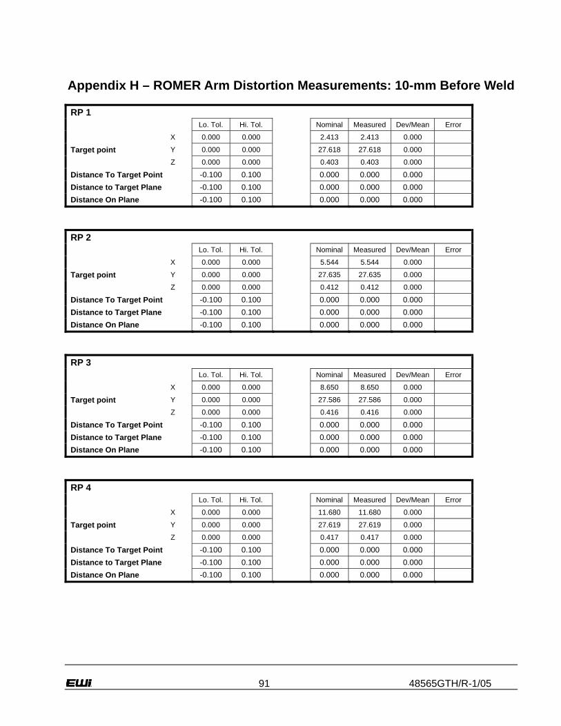
91 48565GTH/R-1/05
Appendix H – ROMER Arm Distortion Measurements: 10-mm Before Weld RP 1 Lo. Tol. Hi. Tol. Nominal Measured Dev/Mean Error
X 0.000 0.000 2.413 2.413 0.000
Target point Y 0.000 0.000 27.618 27.618 0.000
Z 0.000 0.000 0.403 0.403 0.000
Distance To Target Point -0.100 0.100 0.000 0.000 0.000 Distance to Target Plane -0.100 0.100 0.000 0.000 0.000 Distance On Plane -0.100 0.100 0.000 0.000 0.000
RP 2 Lo. Tol. Hi. Tol. Nominal Measured Dev/Mean Error
X 0.000 0.000 5.544 5.544 0.000
Target point Y 0.000 0.000 27.635 27.635 0.000
Z 0.000 0.000 0.412 0.412 0.000
Distance To Target Point -0.100 0.100 0.000 0.000 0.000 Distance to Target Plane -0.100 0.100 0.000 0.000 0.000 Distance On Plane -0.100 0.100 0.000 0.000 0.000
RP 3 Lo. Tol. Hi. Tol. Nominal Measured Dev/Mean Error
X 0.000 0.000 8.650 8.650 0.000
Target point Y 0.000 0.000 27.586 27.586 0.000
Z 0.000 0.000 0.416 0.416 0.000
Distance To Target Point -0.100 0.100 0.000 0.000 0.000 Distance to Target Plane -0.100 0.100 0.000 0.000 0.000 Distance On Plane -0.100 0.100 0.000 0.000 0.000
RP 4 Lo. Tol. Hi. Tol. Nominal Measured Dev/Mean Error
X 0.000 0.000 11.680 11.680 0.000
Target point Y 0.000 0.000 27.619 27.619 0.000
Z 0.000 0.000 0.417 0.417 0.000
Distance To Target Point -0.100 0.100 0.000 0.000 0.000 Distance to Target Plane -0.100 0.100 0.000 0.000 0.000 Distance On Plane -0.100 0.100 0.000 0.000 0.000

92 48565GTH/R-1/05
RP 5 Lo. Tol. Hi. Tol. Nominal Measured Dev/Mean Error
X 0.000 0.000 14.753 14.753 0.000
Target point Y 0.000 0.000 27.554 27.554 0.000
Z 0.000 0.000 0.416 0.416 0.000 0.000
Distance To Target Point -0.100 0.100 0.000 0.000 0.000 Distance to Target Plane -0.100 0.100 0.000 0.000 0.000 Distance On Plane -0.100 0.100 0.000 0.000 0.000
RP 6 Lo. Tol. Hi. Tol. Nominal Measured Dev/Mean Error
X 0.000 0.000 17.984 17.984 0.000
Target point Y 0.000 0.000 27.507 27.507 0.000
Z 0.000 0.000 0.415 0.415 0.000 0.000
Distance To Target Point -0.100 0.100 0.000 0.000 0.000 Distance to Target Plane -0.100 0.100 0.000 0.000 0.000 Distance On Plane -0.100 0.100 0.000 0.000 0.000
RP 7 Lo. Tol. Hi. Tol. Nominal Measured Dev/Mean Error
X 0.000 0.000 20.958 20.958 0.000
Target point Y 0.000 0.000 27.566 27.566 0.000
Z 0.000 0.000 0.414 0.414 0.000 0.000
Distance To Target Point -0.100 0.100 0.000 0.000 0.000 Distance to Target Plane -0.100 0.100 0.000 0.000 0.000 Distance On Plane -0.100 0.100 0.000 0.000 0.000
RP 8 Lo. Tol. Hi. Tol. Nominal Measured Dev/Mean Error
X 0.000 0.000 24.052 24.052 0.000
Target point Y 0.000 0.000 27.463 27.463 0.000
Z 0.000 0.000 0.415 0.415 0.000
Distance To Target Point -0.100 0.100 0.000 0.000 0.000 Distance to Target Plane -0.100 0.100 0.000 0.000 0.000 Distance On Plane -0.100 0.100 0.000 0.000 0.000

93 48565GTH/R-1/05
RP 9 Lo. Tol. Hi. Tol. Nominal Measured Dev/Mean Error
X 0.000 0.000 24.007 24.007 0.000
Target point Y 0.000 0.000 23.729 23.729 0.000
Z 0.000 0.000 0.440 0.440 0.000
Distance To Target Point -0.100 0.100 0.000 0.000 0.000 Distance to Target Plane -0.100 0.100 0.000 0.000 0.000 Distance On Plane -0.100 0.100 0.000 0.000 0.000
RP 10 Lo. Tol. Hi. Tol. Nominal Measured Dev/Mean Error
X 0.000 0.000 21.033 21.033 0.000
Target point Y 0.000 0.000 23.715 23.715 0.000
Z 0.000 0.000 0.434 0.434 0.000 0.000
Distance To Target Point -0.100 0.100 0.000 0.000 0.000 Distance to Target Plane -0.100 0.100 0.000 0.000 0.000 Distance On Plane -0.100 0.100 0.000 0.000 0.000
RP 11 Lo. Tol. Hi. Tol. Nominal Measured Dev/Mean Error
X 0.000 0.000 17.930 17.930 0.000
Target point Y 0.000 0.000 23.826 23.826 0.000
Z 0.000 0.000 0.434 0.434 0.000 0.000
Distance To Target Point -0.100 0.100 0.000 0.000 0.000 Distance to Target Plane -0.100 0.100 0.000 0.000 0.000 Distance On Plane -0.100 0.100 0.000 0.000 0.000
RP 12 Lo. Tol. Hi. Tol. Nominal Measured Dev/Mean Error
X 0.000 0.000 14.775 14.775 0.000
Target point Y 0.000 0.000 23.859 23.859 0.000
Z 0.000 0.000 0.434 0.434 0.000
Distance To Target Point -0.100 0.100 0.000 0.000 0.000 Distance to Target Plane -0.100 0.100 0.000 0.000 0.000 Distance On Plane -0.100 0.100 0.000 0.000 0.000

94 48565GTH/R-1/05
RP 13 Lo. Tol. Hi. Tol. Nominal Measured Dev/Mean Error
X 0.000 0.000 11.564 11.564 0.000
Target point Y 0.000 0.000 23.942 23.942 0.000
Z 0.000 0.000 0.431 0.431 0.000 0.000
Distance To Target Point -0.100 0.100 0.000 0.000 0.000 Distance to Target Plane -0.100 0.100 0.000 0.000 0.000 Distance On Plane -0.100 0.100 0.000 0.000 0.000
RP 14 Lo. Tol. Hi. Tol. Nominal Measured Dev/Mean Error
X 0.000 0.000 8.569 8.569 0.000
Target point Y 0.000 0.000 24.024 24.024 0.000
Z 0.000 0.000 0.426 0.426 0.000 0.000
Distance To Target Point -0.100 0.100 0.000 0.000 0.000 Distance to Target Plane -0.100 0.100 0.000 0.000 0.000 Distance On Plane -0.100 0.100 0.000 0.000 0.000
RP 15 Lo. Tol. Hi. Tol. Nominal Measured Dev/Mean Error
X 0.000 0.000 5.481 5.481 0.000
Target point Y 0.000 0.000 24.011 24.011 0.000
Z 0.000 0.000 0.417 0.417 0.000
Distance To Target Point -0.100 0.100 0.000 0.000 0.000 Distance to Target Plane -0.100 0.100 0.000 0.000 0.000 Distance On Plane -0.100 0.100 0.000 0.000 0.000
RP 16 Lo. Tol. Hi. Tol. Nominal Measured Dev/Mean Error
X 0.000 0.000 2.383 2.383 0.000
Target point Y 0.000 0.000 24.073 24.073 0.000
Z 0.000 0.000 0.407 0.407 0.000
Distance To Target Point -0.100 0.100 0.000 0.000 0.000 Distance to Target Plane -0.100 0.100 0.000 0.000 0.000 Distance On Plane -0.100 0.100 0.000 0.000 0.000

95 48565GTH/R-1/05
RP 17 Lo. Tol. Hi. Tol. Nominal Measured Dev/Mean Error
X 0.000 0.000 2.281 2.281 0.000
Target point Y 0.000 0.000 21.780 21.780 0.000
Z 0.000 0.000 0.413 0.413 0.000 0.000
Distance To Target Point -0.100 0.100 0.000 0.000 0.000 Distance to Target Plane -0.100 0.100 0.000 0.000 0.000 Distance On Plane -0.100 0.100 0.000 0.000 0.000
RP 18 Lo. Tol. Hi. Tol. Nominal Measured Dev/Mean Error
X 0.000 0.000 5.443 5.443 0.000
Target point Y 0.000 0.000 21.749 21.749 0.000
Z 0.000 0.000 0.416 0.416 0.000
Distance To Target Point -0.100 0.100 0.000 0.000 0.000 Distance to Target Plane -0.100 0.100 0.000 0.000 0.000 Distance On Plane -0.100 0.100 0.000 0.000 0.000
RP 19 Lo. Tol. Hi. Tol. Nominal Measured Dev/Mean Error
X 0.000 0.000 8.542 8.542 0.000
Target point Y 0.000 0.000 21.698 21.698 0.000
Z 0.000 0.000 0.422 0.422 0.000
Distance To Target Point -0.100 0.100 0.000 0.000 0.000 Distance to Target Plane -0.100 0.100 0.000 0.000 0.000 Distance On Plane -0.100 0.100 0.000 0.000 0.000
RP 20 Lo. Tol. Hi. Tol. Nominal Measured Dev/Mean Error
X 0.000 0.000 11.647 11.647 0.000
Target point Y 0.000 0.000 21.659 21.659 0.000
Z 0.000 0.000 0.429 0.429 0.000
Distance To Target Point -0.100 0.100 0.000 0.000 0.000 Distance to Target Plane -0.100 0.100 0.000 0.000 0.000 Distance On Plane -0.100 0.100 0.000 0.000 0.000

96 48565GTH/R-1/05
RP 21 Lo. Tol. Hi. Tol. Nominal Measured Dev/Mean Error
X 0.000 0.000 14.764 14.764 0.000
Target point Y 0.000 0.000 21.646 21.646 0.000
Z 0.000 0.000 0.434 0.434 0.000 0.000
Distance To Target Point -0.100 0.100 0.000 0.000 0.000 Distance to Target Plane -0.100 0.100 0.000 0.000 0.000 Distance On Plane -0.100 0.100 0.000 0.000 0.000
RP 22 Lo. Tol. Hi. Tol. Nominal Measured Dev/Mean Error
X 0.000 0.000 17.928 17.928 0.000
Target point Y 0.000 0.000 21.576 21.576 0.000
Z 0.000 0.000 0.436 0.436 0.000
Distance To Target Point -0.100 0.100 0.000 0.000 0.000 Distance to Target Plane -0.100 0.100 0.000 0.000 0.000 Distance On Plane -0.100 0.100 0.000 0.000 0.000
RP 23 Lo. Tol. Hi. Tol. Nominal Measured Dev/Mean Error
X 0.000 0.000 20.981 20.981 0.000
Target point Y 0.000 0.000 21.607 21.607 0.000
Z 0.000 0.000 0.436 0.436 0.000
Distance To Target Point -0.100 0.100 0.000 0.000 0.000 Distance to Target Plane -0.100 0.100 0.000 0.000 0.000 Distance On Plane -0.100 0.100 0.000 0.000 0.000
RP 24 Lo. Tol. Hi. Tol. Nominal Measured Dev/Mean Error
X 0.000 0.000 24.030 24.030 0.000
Target point Y 0.000 0.000 21.563 21.563 0.000
Z 0.000 0.000 0.435 0.435 0.000 0.000
Distance To Target Point -0.100 0.100 0.000 0.000 0.000 Distance to Target Plane -0.100 0.100 0.000 0.000 0.000 Distance On Plane -0.100 0.100 0.000 0.000 0.000

97 48565GTH/R-1/05
RP 25 Lo. Tol. Hi. Tol. Nominal Measured Dev/Mean Error
X 0.000 0.000 24.015 24.015 0.000
Target point Y 0.000 0.000 17.860 17.860 0.000
Z 0.000 0.000 0.424 0.424 0.000 0.000
Distance To Target Point -0.100 0.100 0.000 0.000 0.000 Distance to Target Plane -0.100 0.100 0.000 0.000 0.000 Distance On Plane -0.100 0.100 0.000 0.000 0.000
RP 26 Lo. Tol. Hi. Tol. Nominal Measured Dev/Mean Error
X 0.000 0.000 20.952 20.952 0.000
Target point Y 0.000 0.000 17.933 17.933 0.000
Z 0.000 0.000 0.421 0.421 0.000 0.000
Distance To Target Point -0.100 0.100 0.000 0.000 0.000 Distance to Target Plane -0.100 0.100 0.000 0.000 0.000 Distance On Plane -0.100 0.100 0.000 0.000 0.000
RP 27 Lo. Tol. Hi. Tol. Nominal Measured Dev/Mean Error
X 0.000 0.000 17.834 17.834 0.000
Target point Y 0.000 0.000 17.913 17.913 0.000
Z 0.000 0.000 0.422 0.422 0.000
Distance To Target Point -0.100 0.100 0.000 0.000 0.000 Distance to Target Plane -0.100 0.100 0.000 0.000 0.000 Distance On Plane -0.100 0.100 0.000 0.000 0.000
RP 28 Lo. Tol. Hi. Tol. Nominal Measured Dev/Mean Error
X 0.000 0.000 14.680 14.680 0.000
Target point Y 0.000 0.000 17.969 17.969 0.000
Z 0.000 0.000 0.415 0.415 0.000 0.000
Distance To Target Point -0.100 0.100 0.000 0.000 0.000 Distance to Target Plane -0.100 0.100 0.000 0.000 0.000 Distance On Plane -0.100 0.100 0.000 0.000 0.000

98 48565GTH/R-1/05
RP 29 Lo. Tol. Hi. Tol. Nominal Measured Dev/Mean Error
X 0.000 0.000 11.474 11.474 0.000
Target point Y 0.000 0.000 18.087 18.087 0.000
Z 0.000 0.000 0.407 0.407 0.000 0.000
Distance To Target Point -0.100 0.100 0.000 0.000 0.000 Distance to Target Plane -0.100 0.100 0.000 0.000 0.000 Distance On Plane -0.100 0.100 0.000 0.000 0.000
RP 30 Lo. Tol. Hi. Tol. Nominal Measured Dev/Mean Error
X 0.000 0.000 8.505 8.505 0.000
Target point Y 0.000 0.000 18.089 18.089 0.000
Z 0.000 0.000 0.399 0.399 0.000
Distance To Target Point -0.100 0.100 0.000 0.000 0.000 Distance to Target Plane -0.100 0.100 0.000 0.000 0.000 Distance On Plane -0.100 0.100 0.000 0.000 0.000
RP 31 Lo. Tol. Hi. Tol. Nominal Measured Dev/Mean Error
X 0.000 0.000 5.430 5.430 0.000
Target point Y 0.000 0.000 18.094 18.094 0.000
Z 0.000 0.000 0.391 0.391 0.000
Distance To Target Point -0.100 0.100 0.000 0.000 0.000 Distance to Target Plane -0.100 0.100 0.000 0.000 0.000 Distance On Plane -0.100 0.100 0.000 0.000 0.000
RP 32 Lo. Tol. Hi. Tol. Nominal Measured Dev/Mean Error
X 0.000 0.000 2.240 2.240 0.000
Target point Y 0.000 0.000 18.178 18.178 0.000
Z 0.000 0.000 0.384 0.384 0.000
Distance To Target Point -0.100 0.100 0.000 0.000 0.000 Distance to Target Plane -0.100 0.100 0.000 0.000 0.000 Distance On Plane -0.100 0.100 0.000 0.000 0.000

99 48565GTH/R-1/05
Appendix I – ROMER Arm Distortion Measurements 10-mm After Weld
RP 1 Lo. Tol. Hi. Tol. Nominal Measured Dev/Mean Error
X 0.000 0.000 0.900 0.900 0.000
Target point Y 0.000 0.000 27.446 27.446 0.000
Z 0.000 0.000 0.430 0.430 0.000
Distance To Target Point -0.100 0.100 0.000 0.000 0.000 Distance to Target Plane -0.100 0.100 0.000 0.000 0.000 Distance On Plane -0.100 0.100 0.000 0.000 0.000
RP 2 Lo. Tol. Hi. Tol. Nominal Measured Dev/Mean Error
X 0.000 0.000 3.930 3.930 0.000
Target point Y 0.000 0.000 27.515 27.515 0.000
Z 0.000 0.000 0.423 0.423 0.000
Distance To Target Point -0.100 0.100 0.000 0.000 0.000 Distance to Target Plane -0.100 0.100 0.000 0.000 0.000 Distance On Plane -0.100 0.100 0.000 0.000 0.000
RP 3 Lo. Tol. Hi. Tol. Nominal Measured Dev/Mean Error
X 0.000 0.000 7.084 7.084 0.000
Target point Y 0.000 0.000 27.494 27.494 0.000
Z 0.000 0.000 0.417 0.417 0.000
Distance To Target Point -0.100 0.100 0.000 0.000 0.000 Distance to Target Plane -0.100 0.100 0.000 0.000 0.000 Distance On Plane -0.100 0.100 0.000 0.000 0.000
RP 4 Lo. Tol. Hi. Tol. Nominal Measured Dev/Mean Error
X 0.000 0.000 10.048 10.048 0.000
Target point Y 0.000 0.000 27.414 27.414 0.000
Z 0.000 0.000 0.411 0.411 0.000
Distance To Target Point -0.100 0.100 0.000 0.000 0.000 Distance to Target Plane -0.100 0.100 0.000 0.000 0.000 Distance On Plane -0.100 0.100 0.000 0.000 0.000

100 48565GTH/R-1/05
RP 5 Lo. Tol. Hi. Tol. Nominal Measured Dev/Mean Error
X 0.000 0.000 13.147 13.147 0.000
Target point Y 0.000 0.000 27.510 27.510 0.000
Z 0.000 0.000 0.409 0.409 0.000
Distance To Target Point -0.100 0.100 0.000 0.000 0.000 Distance to Target Plane -0.100 0.100 0.000 0.000 0.000 Distance On Plane -0.100 0.100 0.000 0.000 0.000
RP 6 Lo. Tol. Hi. Tol. Nominal Measured Dev/Mean Error
X 0.000 0.000 16.287 16.287 0.000
Target point Y 0.000 0.000 27.478 27.478 0.000
Z 0.000 0.000 0.413 0.413 0.000
Distance To Target Point -0.100 0.100 0.000 0.000 0.000 Distance to Target Plane -0.100 0.100 0.000 0.000 0.000 Distance On Plane -0.100 0.100 0.000 0.000 0.000
RP 7 Lo. Tol. Hi. Tol. Nominal Measured Dev/Mean Error
X 0.000 0.000 19.338 19.338 0.000
Target point Y 0.000 0.000 27.582 27.582 0.000
Z 0.000 0.000 0.422 0.422 0.000
Distance To Target Point -0.100 0.100 0.000 0.000 0.000 Distance to Target Plane -0.100 0.100 0.000 0.000 0.000 Distance On Plane -0.100 0.100 0.000 0.000 0.000
RP 8 Lo. Tol. Hi. Tol. Nominal Measured Dev/Mean Error
X 0.000 0.000 22.454 22.454 0.000
Target point Y 0.000 0.000 27.672 27.672 0.000
Z 0.000 0.000 0.434 0.434 0.000
Distance To Target Point -0.100 0.100 0.000 0.000 0.000 Distance to Target Plane -0.100 0.100 0.000 0.000 0.000 Distance On Plane -0.100 0.100 0.000 0.000 0.000

101 48565GTH/R-1/05
RP 9 Lo. Tol. Hi. Tol. Nominal Measured Dev/Mean Error
X 0.000 0.000 22.575 22.575 0.000
Target point Y 0.000 0.000 23.837 23.837 0.000
Z 0.000 0.000 0.465 0.465 0.000
Distance To Target Point -0.100 0.100 0.000 0.000 0.000 Distance to Target Plane -0.100 0.100 0.000 0.000 0.000 Distance On Plane -0.100 0.100 0.000 0.000 0.000
RP 10 Lo. Tol. Hi. Tol. Nominal Measured Dev/Mean Error
X 0.000 0.000 19.509 19.509 0.000
Target point Y 0.000 0.000 23.628 23.628 0.000
Z 0.000 0.000 0.450 0.450 0.000
Distance To Target Point -0.100 0.100 0.000 0.000 0.000 Distance to Target Plane -0.100 0.100 0.000 0.000 0.000 Distance On Plane -0.100 0.100 0.000 0.000 0.000
RP 11 Lo. Tol. Hi. Tol. Nominal Measured Dev/Mean Error
X 0.000 0.000 16.341 16.341 0.000
Target point Y 0.000 0.000 23.564 23.564 0.000
Z 0.000 0.000 0.438 0.438 0.000
Distance To Target Point -0.100 0.100 0.000 0.000 0.000 Distance to Target Plane -0.100 0.100 0.000 0.000 0.000 Distance On Plane -0.100 0.100 0.000 0.000 0.000
RP 12 Lo. Tol. Hi. Tol. Nominal Measured Dev/Mean Error
X 0.000 0.000 13.274 13.274 0.000
Target point Y 0.000 0.000 23.595 23.595 0.000
Z 0.000 0.000 0.431 0.431 0.000
Distance To Target Point -0.100 0.100 0.000 0.000 0.000 Distance to Target Plane -0.100 0.100 0.000 0.000 0.000 Distance On Plane -0.100 0.100 0.000 0.000 0.000

102 48565GTH/R-1/05
RP 13 Lo. Tol. Hi. Tol. Nominal Measured Dev/Mean Error
X 0.000 0.000 10.050 10.050 0.000
Target point Y 0.000 0.000 23.522 23.522 0.000
Z 0.000 0.000 0.429 0.429 0.000
Distance To Target Point -0.100 0.100 0.000 0.000 0.000 Distance to Target Plane -0.100 0.100 0.000 0.000 0.000 Distance On Plane -0.100 0.100 0.000 0.000 0.000
RP 14 Lo. Tol. Hi. Tol. Nominal Measured Dev/Mean Error
X 0.000 0.000 7.006 7.006 0.000
Target point Y 0.000 0.000 23.713 23.713 0.000
Z 0.000 0.000 0.430 0.430 0.000
Distance To Target Point -0.100 0.100 0.000 0.000 0.000 Distance to Target Plane -0.100 0.100 0.000 0.000 0.000 Distance On Plane -0.100 0.100 0.000 0.000 0.000
RP 15 Lo. Tol. Hi. Tol. Nominal Measured Dev/Mean Error
X 0.000 0.000 3.875 3.875 0.000
Target point Y 0.000 0.000 23.587 23.587 0.000
Z 0.000 0.000 0.434 0.434 0.000
Distance To Target Point -0.100 0.100 0.000 0.000 0.000 Distance to Target Plane -0.100 0.100 0.000 0.000 0.000 Distance On Plane -0.100 0.100 0.000 0.000 0.000
RP 16 Lo. Tol. Hi. Tol. Nominal Measured Dev/Mean Error
X 0.000 0.000 0.890 0.890 0.000
Target point Y 0.000 0.000 23.390 23.390 0.000
Z 0.000 0.000 0.442 0.442 0.000
Distance To Target Point -0.100 0.100 0.000 0.000 0.000 Distance to Target Plane -0.100 0.100 0.000 0.000 0.000 Distance On Plane -0.100 0.100 0.000 0.000 0.000

103 48565GTH/R-1/05
RP 17 Lo. Tol. Hi. Tol. Nominal Measured Dev/Mean Error
X 0.000 0.000 0.752 0.752 0.000
Target point Y 0.000 0.000 21.748 21.748 0.000
Z 0.000 0.000 0.448 0.448 0.000
Distance To Target Point -0.100 0.100 0.000 0.000 0.000 Distance to Target Plane -0.100 0.100 0.000 0.000 0.000 Distance On Plane -0.100 0.100 0.000 0.000 0.000
RP 18 Lo. Tol. Hi. Tol. Nominal Measured Dev/Mean Error
X 0.000 0.000 3.946 3.946 0.000
Target point Y 0.000 0.000 21.629 21.629 0.000
Z 0.000 0.000 0.440 0.440 0.000
Distance To Target Point -0.100 0.100 0.000 0.000 0.000 Distance to Target Plane -0.100 0.100 0.000 0.000 0.000 Distance On Plane -0.100 0.100 0.000 0.000 0.000
RP 19 Lo. Tol. Hi. Tol. Nominal Measured Dev/Mean Error
X 0.000 0.000 7.120 7.120 0.000
Target point Y 0.000 0.000 21.700 21.700 0.000
Z 0.000 0.000 0.437 0.437 0.000
Distance To Target Point -0.100 0.100 0.000 0.000 0.000 Distance to Target Plane -0.100 0.100 0.000 0.000 0.000 Distance On Plane -0.100 0.100 0.000 0.000 0.000
RP 20 Lo. Tol. Hi. Tol. Nominal Measured Dev/Mean Error
X 0.000 0.000 10.074 10.074 0.000
Target point Y 0.000 0.000 21.532 21.532 0.000
Z 0.000 0.000 0.438 0.438 0.000
Distance To Target Point -0.100 0.100 0.000 0.000 0.000 Distance to Target Plane -0.100 0.100 0.000 0.000 0.000 Distance On Plane -0.100 0.100 0.000 0.000 0.000

104 48565GTH/R-1/05
RP 21 Lo. Tol. Hi. Tol. Nominal Measured Dev/Mean Error
X 0.000 0.000 13.173 13.173 0.000
Target point Y 0.000 0.000 21.730 21.730 0.000
Z 0.000 0.000 0.442 0.442 0.000
Distance To Target Point -0.100 0.100 0.000 0.000 0.000 Distance to Target Plane -0.100 0.100 0.000 0.000 0.000 Distance On Plane -0.100 0.100 0.000 0.000 0.000
RP 22 Lo. Tol. Hi. Tol. Nominal Measured Dev/Mean Error
X 0.000 0.000 16.328 16.328 0.000
Target point Y 0.000 0.000 21.710 21.710 0.000
Z 0.000 0.000 0.449 0.449 0.000
Distance To Target Point -0.100 0.100 0.000 0.000 0.000 Distance to Target Plane -0.100 0.100 0.000 0.000 0.000 Distance On Plane -0.100 0.100 0.000 0.000 0.000
RP 23 Lo. Tol. Hi. Tol. Nominal Measured Dev/Mean Error
X 0.000 0.000 19.520 19.520 0.000
Target point Y 0.000 0.000 21.633 21.633 0.000
Z 0.000 0.000 0.460 0.460 0.000
Distance To Target Point -0.100 0.100 0.000 0.000 0.000 Distance to Target Plane -0.100 0.100 0.000 0.000 0.000 Distance On Plane -0.100 0.100 0.000 0.000 0.000
RP 24 Lo. Tol. Hi. Tol. Nominal Measured Dev/Mean Error
X 0.000 0.000 22.574 22.574 0.000
Target point Y 0.000 0.000 21.685 21.685 0.000
Z 0.000 0.000 0.470 0.470 0.000
Distance To Target Point -0.100 0.100 0.000 0.000 0.000 Distance to Target Plane -0.100 0.100 0.000 0.000 0.000 Distance On Plane -0.100 0.100 0.000 0.000 0.000

105 48565GTH/R-1/05
RP 25 Lo. Tol. Hi. Tol. Nominal Measured Dev/Mean Error
X 0.000 0.000 22.544 22.544 0.000
Target point Y 0.000 0.000 18.119 18.119 0.000
Z 0.000 0.000 0.483 0.483 0.000
Distance To Target Point -0.100 0.100 0.000 0.000 0.000 Distance to Target Plane -0.100 0.100 0.000 0.000 0.000 Distance On Plane -0.100 0.100 0.000 0.000 0.000
RP 26 Lo. Tol. Hi. Tol. Nominal Measured Dev/Mean Error
X 0.000 0.000 19.441 19.441 0.000
Target point Y 0.000 0.000 17.990 17.990 0.000
Z 0.000 0.000 0.475 0.475 0.000
Distance To Target Point -0.100 0.100 0.000 0.000 0.000 Distance to Target Plane -0.100 0.100 0.000 0.000 0.000 Distance On Plane -0.100 0.100 0.000 0.000 0.000
RP 27 Lo. Tol. Hi. Tol. Nominal Measured Dev/Mean Error
X 0.000 0.000 16.298 16.298 0.000
Target point Y 0.000 0.000 17.954 17.954 0.000
Z 0.000 0.000 0.462 0.462 0.000
Distance To Target Point -0.100 0.100 0.000 0.000 0.000 Distance to Target Plane -0.100 0.100 0.000 0.000 0.000 Distance On Plane -0.100 0.100 0.000 0.000 0.000
RP 28 Lo. Tol. Hi. Tol. Nominal Measured Dev/Mean Error
X 0.000 0.000 13.274 13.274 0.000
Target point Y 0.000 0.000 18.015 18.015 0.000
Z 0.000 0.000 0.450 0.450 0.000
Distance To Target Point -0.100 0.100 0.000 0.000 0.000 Distance to Target Plane -0.100 0.100 0.000 0.000 0.000 Distance On Plane -0.100 0.100 0.000 0.000 0.000

106 48565GTH/R-1/05
RP 29 Lo. Tol. Hi. Tol. Nominal Measured Dev/Mean Error
X 0.000 0.000 10.046 10.046 0.000
Target point Y 0.000 0.000 18.082 18.082 0.000
Z 0.000 0.000 0.443 0.443 0.000
Distance To Target Point -0.100 0.100 0.000 0.000 0.000 Distance to Target Plane -0.100 0.100 0.000 0.000 0.000 Distance On Plane -0.100 0.100 0.000 0.000 0.000
RP 30 Lo. Tol. Hi. Tol. Nominal Measured Dev/Mean Error
X 0.000 0.000 7.162 7.162 0.000
Target point Y 0.000 0.000 18.019 18.019 0.000
Z 0.000 0.000 0.439 0.439 0.000
Distance To Target Point -0.100 0.100 0.000 0.000 0.000 Distance to Target Plane -0.100 0.100 0.000 0.000 0.000 Distance On Plane -0.100 0.100 0.000 0.000 0.000
RP 31 Lo. Tol. Hi. Tol. Nominal Measured Dev/Mean Error
X 0.000 0.000 4.049 4.049 0.000
Target point Y 0.000 0.000 17.984 17.984 0.000
Z 0.000 0.000 0.441 0.441 0.000
Distance To Target Point -0.100 0.100 0.000 0.000 0.000 Distance to Target Plane -0.100 0.100 0.000 0.000 0.000 Distance On Plane -0.100 0.100 0.000 0.000 0.000
RP 32 Lo. Tol. Hi. Tol. Nominal Measured Dev/Mean Error
X 0.000 0.000 0.891 0.891 0.000
Target point Y 0.000 0.000 18.042 18.042 0.000
Z 0.000 0.000 0.442 0.442 0.000
Distance To Target Point -0.100 0.100 0.000 0.000 0.000 Distance to Target Plane -0.100 0.100 0.000 0.000 0.000 Distance On Plane -0.100 0.100 0.000 0.000 0.000
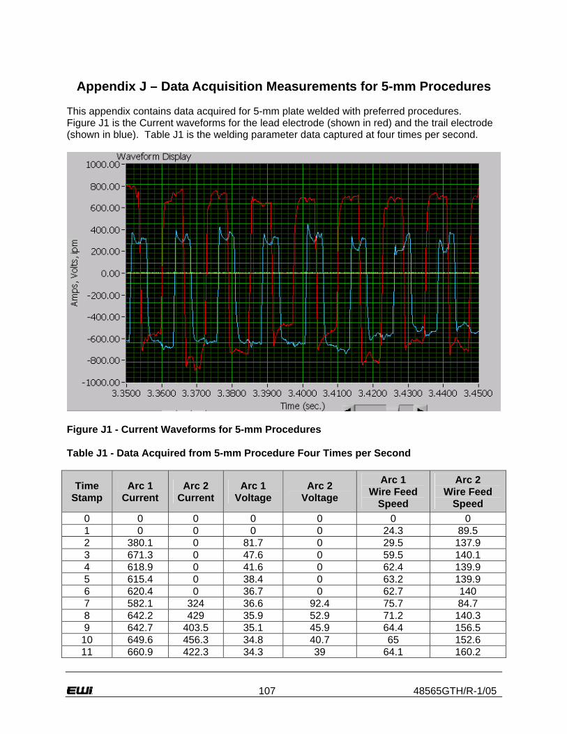
107 48565GTH/R-1/05
Appendix J – Data Acquisition Measurements for 5-mm Procedures
This appendix contains data acquired for 5-mm plate welded with preferred procedures. Figure J1 is the Current waveforms for the lead electrode (shown in red) and the trail electrode (shown in blue). Table J1 is the welding parameter data captured at four times per second.
Figure J1 - Current Waveforms for 5-mm Procedures Table J1 - Data Acquired from 5-mm Procedure Four Times per Second
Time Stamp
Arc 1 Current
Arc 2 Current
Arc 1 Voltage
Arc 2 Voltage
Arc 1 Wire Feed
Speed
Arc 2 Wire Feed
Speed 0 0 0 0 0 0 0 1 0 0 0 0 24.3 89.5 2 380.1 0 81.7 0 29.5 137.9 3 671.3 0 47.6 0 59.5 140.1 4 618.9 0 41.6 0 62.4 139.9 5 615.4 0 38.4 0 63.2 139.9 6 620.4 0 36.7 0 62.7 140 7 582.1 324 36.6 92.4 75.7 84.7 8 642.2 429 35.9 52.9 71.2 140.3 9 642.7 403.5 35.1 45.9 64.4 156.5
10 649.6 456.3 34.8 40.7 65 152.6 11 660.9 422.3 34.3 39 64.1 160.2

108 48565GTH/R-1/05
12 664.1 443.3 33.6 37.3 63.3 151.1 13 659.6 483.2 33.6 36.3 64.2 172.4 14 647.7 473.3 33.7 36 64.2 144.3 15 646.7 480.1 33.8 35.9 64.5 156.1 16 659.5 489.4 33.2 35.6 62.9 155.5 17 653.1 473.5 33.2 36 63.7 184.9 18 661.7 504.7 33.2 35.7 64 163.3 19 660.6 489.9 33 35.8 63.6 151.8 20 651.1 497.8 32.9 36 64 204.5 21 655.7 491.1 32.7 35.7 63.6 155.4 22 654.8 508 32.8 35.9 63.5 186.6 23 637.9 490.5 33.3 36 64.8 150.2 24 625.7 492.3 33.7 36.3 66.5 198.4 25 654.4 487.4 33.1 36 64.1 175.1 26 657.9 507.1 32.9 35.8 63.8 160.3 27 668.8 495.5 32.4 36.3 62.7 204.5 28 659.8 486.8 32.4 36.5 63.1 157.3 29 660.2 497.6 32 36.1 62.5 182.9 30 665 487.6 32 36.1 62.3 189.9 31 647 479.4 32.6 36.3 62.6 173.8 32 650.9 495.6 32.3 36.1 62.2 159.9 33 659.7 493.7 32 36.4 62.1 183.7 34 654.3 492.7 32.1 36.7 62.1 151.5 35 657.1 497.9 31.9 36.3 61.7 161.3 36 661.2 487.4 31.8 36.4 61.1 200.6 37 655.4 499.3 31.8 36.5 61.5 161.1 38 657 498.1 32 36.5 60.6 166.8 39 650.7 493.9 31.9 37 61.1 206.2 40 658 508 31.7 36.8 61 182.4 41 667.7 514 31.3 36.6 59.3 181.2 42 635.2 507 32.5 36.1 62.5 178.9 43 651.9 515.7 32.1 36 60.2 199.4 44 661 505.7 31.6 35.9 60.8 177.2 45 645.1 483.3 32.1 36.3 60.8 215 46 653.4 514.3 32 35.3 60.6 180.8 47 654.3 509.8 32 35.4 60.1 187 48 653.2 508 32 35.6 59.9 190.4 49 662.9 500.5 31.6 35.4 59.2 198.3 50 652.5 508.8 31.9 35.1 59.6 183.5 51 641.7 515.2 32.3 35.1 60.1 178.9 52 657.2 519.6 32 35.1 59.7 184.4 53 654 512.2 32.2 34.9 59.9 188.4 54 644.9 507.8 32.1 34.9 58.8 192.8 55 640.7 512.5 32.6 34.7 59.7 188.5 56 640.3 512.7 32.7 34.5 60.2 188.6 57 638.8 483.8 32.7 34.8 60.5 188.8 58 654.4 513.3 32.5 34.4 59.6 181.3 59 656.9 491.3 32.4 34.7 59.3 193.6

109 48565GTH/R-1/05
60 643.1 501.7 32.7 34.4 60.4 189 61 634.2 516.6 33.2 34.2 61 187.9 62 644.1 509.3 33 34 59.6 191.9 63 649.2 513.2 33 33.8 60.5 191.6 64 655.1 506.8 33 34.2 60.2 194.8 65 663.5 499.7 32.7 34.3 60.3 189.3 66 658.8 521.3 32.7 34.1 59.7 191.6 67 669.6 521.2 32.5 33.8 59.9 190.2 68 650.8 510.8 32.9 33.4 60.5 186.7 69 655.4 513.7 32.6 33.3 59.2 190.2 70 649.8 510.1 32.7 33.2 60.3 187.2 71 652.4 515.9 32.7 33.1 59.4 186.5 72 646.5 515.2 32.9 33.3 60 191.2 73 655.6 496.2 32.9 33.7 60.3 189.8 74 644.5 499.8 32.9 33.4 59.7 190 75 640 517.1 33.2 33.1 60.7 185.4 76 649.2 519.5 33.3 32.8 60 186.1 77 649.8 498.4 33 33.1 60.3 190.7 78 654.3 523.1 32.9 32.8 60.1 184.7 79 646.1 518.7 33 32.5 59.8 185.3 80 647.2 491.9 33.3 33.2 60.2 190.4 81 647.9 492 33 33.2 60.1 191.1 82 646.2 510.8 33.1 33 60.7 186.6 83 659 496.1 32.9 33.2 59.6 190.7 84 639.1 497.2 33.2 33.1 60.2 188.1 85 656.6 500.2 32.8 32.9 59.1 187 86 656.3 516.5 32.9 32.4 60.9 184 87 645.5 509.7 33.1 32.6 60.1 186.6 88 640.8 513.9 33.2 32.8 60.4 188.4 89 653.2 491.7 32.8 33 60.5 190 90 651.4 504.9 32.8 33 60.3 192.1 91 648.1 523.2 32.8 32.5 59.5 186.1 92 650.1 498.8 32.8 33.1 60.7 187.5 93 647.6 499.9 32.7 33.1 58.5 193.6 94 649.8 511 32.8 32.9 59.7 186.3 95 646.8 502.2 33 32.9 60.1 187.2 96 647.2 492.1 33 34.1 60.2 204.7 97 633.9 502.8 33.3 33.6 61.4 187.8 98 651.1 501.8 32.9 33.1 59.6 190.3 99 653.1 502 32.8 33.1 59.8 189
100 642.6 503.8 33 33 60.2 192.1 101 642.6 501.7 33.4 32.9 61 193.9 102 678.2 496.1 32.6 33.4 58.7 197.7 103 637.7 506.2 33.2 33.2 61.2 189.3 104 652.4 495 33.2 33.4 59.7 192.1 105 629.7 494.2 33.3 33.7 61.7 192.2 106 653.6 498.8 33.3 33.5 61 190.4 107 639.7 482.9 33.7 33.7 62.2 193.6

110 48565GTH/R-1/05
108 655.5 514.9 33.7 32.9 62.1 187.1 109 647 489.4 33.6 33.3 61.4 190.6 110 642.3 507.8 33.8 33.1 61.5 188.5 111 650.6 521 33.6 32.7 61.4 188.1 112 657.6 492 33.2 33.3 61 193.8 113 658 516.3 33.2 33 61 189.7 114 668.1 520.2 32.7 32.6 60.5 188 115 655 476.5 33 33.4 60.9 193.8 116 654.1 505 33.1 32.9 60.8 186.9 117 648.7 499.7 33.1 33 61 194.9 118 655.1 504.6 32.9 32.8 61 186.8 119 665.1 499 32.5 33 59.5 191.9 120 652.6 492.3 32.5 33.2 60.4 191.9 121 644.1 506.2 32.7 32.8 60.8 187.8 122 645.6 507.8 32.9 32.8 60.9 185.9 123 683.8 496 31.8 33 58.6 194.4 124 672.9 506.5 31.8 33 57.6 186 125 646.2 504.2 32.2 32.5 59.8 186.9 126 630.2 496 32.8 32.7 61.1 189.7 127 634.5 491.5 33.1 32.6 60 188.5 128 632.8 496 33.5 32.5 60.4 183.9 129 661.7 503.7 33 31.9 59.8 185.5 130 644 509.1 33 31.6 60.8 180.9 131 642.7 468.2 33.1 32.7 60.5 192.2 132 649.1 502.3 33 32.5 60.1 186.2 133 650.9 490.1 32.8 32.9 60.3 187.7 134 657.9 475.7 32.9 33.3 60.4 187.6 135 648.4 491.6 32.9 33 60.6 188.1 136 651.5 507.3 33 32.5 60.3 184.9 137 647.1 503.5 33 32.1 60.2 183 138 649.9 479.9 32.9 32.5 60.1 185.7 139 664 489.8 32.5 32.7 59.7 189 140 663.1 513.1 32.4 32.7 58.8 188.3 141 641.2 515.5 32.9 32 60.3 182.6 142 666 498.8 32.5 32 58.9 183.3 143 652.5 514.9 32.8 31.9 59.8 182.8 144 643.5 482.1 32.9 32.2 60.1 182.3 145 649.9 505.8 32.9 32.1 60.2 184.5 146 637.7 503.3 33.1 32 60.2 182.3 147 650.2 503.9 33.2 32.1 59.9 182 148 644.2 492.1 33.4 32.4 60.7 185.1 149 643.3 495.9 33.2 32.2 60 181.7 150 646.2 498.1 33.3 32 60.7 180.6 151 637.2 516.1 33.4 31.8 61 179.1 152 643.3 506 33.5 31.8 61.2 180.1 153 659.7 492.8 33 32 60.5 180.2 154 631.9 497.8 33.2 33 60.6 0 155 570.7 0 34.1 0 56.4 0

111 48565GTH/R-1/05
156 612.9 0 36.4 0 0 0 157 557.1 0 41.3 0 0 0 158 405.9 0 48.7 0 0 0 159 0 0 0 0 0 0 160 0 0 0 0 0 0 161 0 0 0 0 0 0
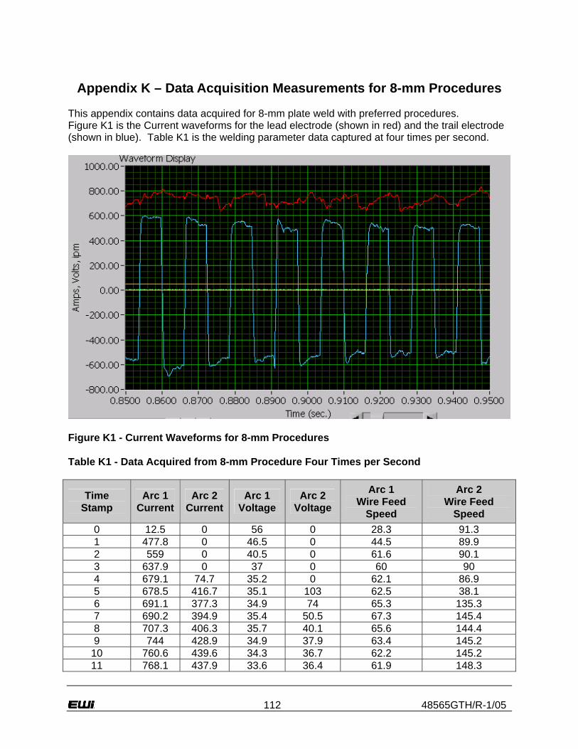
112 48565GTH/R-1/05
Appendix K – Data Acquisition Measurements for 8-mm Procedures
This appendix contains data acquired for 8-mm plate weld with preferred procedures. Figure K1 is the Current waveforms for the lead electrode (shown in red) and the trail electrode (shown in blue). Table K1 is the welding parameter data captured at four times per second.
Figure K1 - Current Waveforms for 8-mm Procedures Table K1 - Data Acquired from 8-mm Procedure Four Times per Second
Time Stamp
Arc 1 Current
Arc 2 Current
Arc 1 Voltage
Arc 2 Voltage
Arc 1 Wire Feed
Speed
Arc 2 Wire Feed
Speed 0 12.5 0 56 0 28.3 91.3 1 477.8 0 46.5 0 44.5 89.9 2 559 0 40.5 0 61.6 90.1 3 637.9 0 37 0 60 90 4 679.1 74.7 35.2 0 62.1 86.9 5 678.5 416.7 35.1 103 62.5 38.1 6 691.1 377.3 34.9 74 65.3 135.3 7 690.2 394.9 35.4 50.5 67.3 145.4 8 707.3 406.3 35.7 40.1 65.6 144.4 9 744 428.9 34.9 37.9 63.4 145.2
10 760.6 439.6 34.3 36.7 62.2 145.2 11 768.1 437.9 33.6 36.4 61.9 148.3

113 48565GTH/R-1/05
12 772.2 438.6 33.4 36.3 61.5 151.1 13 760.7 448.9 33.2 36.5 61.2 145.1 14 747.1 451.3 33.6 36.8 62.3 149.7 15 753.6 473.2 33.6 36.6 61.2 151.1 16 750.4 467.6 33.5 36.5 61.7 152.8 17 754.8 499 33.5 36.3 61 157.6 18 744 482.3 33.9 36.6 62.6 152.5 19 749.9 485.1 33.9 36.5 61.8 156.8 20 745.1 476.6 33.9 36.9 62 176.5 21 744.6 482.9 33.8 36.9 62.3 197.9 22 741.6 511.8 33.8 36.4 61.8 153.6 23 744.5 484.1 33.8 36.9 62 179.6 24 745.2 510.7 33.6 36.3 61.5 161.3 25 752 482.1 33.4 36.6 60.7 183.5 26 751.1 502.9 33.3 36.3 60.9 152.8 27 751.1 503.5 33.5 36.4 61 162.6 28 750.2 487.5 33.7 36.7 61.8 158.9 29 754.9 498.5 33.4 36.5 61.2 163.3 30 755.2 506.3 33.4 36.6 60.6 164.3 31 740.6 503.2 33.8 36.7 62.2 183.6 32 738.5 500.4 34.1 36.4 61.7 158.7 33 741.9 493 34 36.6 62.3 167.5 34 743.2 511.1 34.1 36.2 62.2 167 35 744.7 517.8 34.4 35.8 61.7 165.1 36 746.6 494.5 34.3 36.1 62.4 174.2 37 750.5 491.6 34.1 36.3 62.3 176.7 38 752.6 500.2 33.8 36.6 61.1 184.6 39 755.7 500.2 33.4 36.4 60.8 163.4 40 753.2 489.6 33.5 36.7 60.2 158 41 741.1 507 34.2 36.5 61.7 182.8 42 737.2 503.2 34.2 36.6 61.7 178.7 43 741.5 519.4 34.3 36.2 61.6 167.9 44 741.5 498.1 34.2 36.3 62.4 172.5 45 756.1 501.3 33.6 36.2 60.8 175.9 46 743.4 519.4 33.9 36.1 61.3 205.9 47 739.6 496.3 34.3 35.8 61.7 175.9 48 748.2 506.5 34 36.1 61.5 173.5 49 744.8 514.8 34.2 35.8 61.3 173.9 50 750.2 499.5 33.9 36.1 61 172.1 51 758.5 508.7 33.3 35.8 60.8 176.7 52 758 503.6 33.5 35.7 61.1 177.9 53 752.4 489.5 33.7 36 61 181.6 54 753.4 514.3 33.7 35.5 61.1 176.1 55 744.5 491.9 33.8 36.1 61.7 180.8 56 754.1 513.8 33.6 35.5 60.6 138.5 57 753.2 498.2 33.7 35.5 61.1 179.6 58 747 512.9 33.6 35.5 60.7 177.4 59 752.9 510.5 33.5 35.3 60.6 178.9

114 48565GTH/R-1/05
60 753.1 505.7 33.6 35.2 60.8 180.4 61 746.2 515.6 33.9 34.9 61.1 177.6 62 754.7 497.2 33.7 35.1 61 180.5 63 745 514.4 33.8 34.6 60.5 178.7 64 740.7 508.7 33.8 34.8 60.8 178.8 65 743 516.4 33.8 34.2 61.4 178.9 66 743.2 500.5 33.9 34.6 61.3 179.5 67 736.8 503.2 34.1 34.5 61.3 179.2 68 743 491 34.1 34.9 61.2 181.1 69 744.8 511.3 34 34.5 61.2 180.4 70 751.9 515.4 33.7 34.3 60.2 178.1 71 750.3 501.6 33.8 34.5 61.1 182.2 72 752.4 517.5 33.7 34.1 60.8 178.1 73 751.6 503.6 33.7 33.9 60.8 175.9 74 755.8 503.1 33.7 34.1 60.8 180.6 75 757 509 33.7 33.9 61 178 76 749.7 506.7 33.9 34.3 60.5 174.8 77 744.3 492.7 34 34.2 61.5 182.6 78 748.3 509.3 34 33.7 60.9 176.5 79 742 517.6 34.3 33.5 60.9 174.8 80 745.4 503.7 33.9 33.3 60.7 175.9 81 739.9 484.3 34.3 33.6 61.6 181.5 82 741.9 502.7 34.1 33.5 61.8 176.5 83 745.4 499 33.9 33.8 60.9 176 84 751.8 486 34 34.1 61.3 183.8 85 748.8 502.7 34.1 33.9 61.4 176.3 86 742.8 514.1 34.4 33.5 61.2 177 87 747.8 471.3 33.8 34.5 61.9 183.5 88 749.5 498.3 33.7 34.5 60.6 178.7 89 754.6 517.8 33.6 33.8 61.5 174.2 90 753.1 514.3 34 33.6 61.5 172.9 91 747.3 513.8 33.9 33.3 61.9 173.7 92 746.6 504.4 33.9 33.4 60.3 175.6 93 766.5 503.7 33.2 33.7 60.1 179.4 94 762 483.1 33.4 34 60.1 178 95 750.9 498.4 33.7 33.7 62.3 177.7 96 748.7 499.6 33.9 33.7 60.8 174.5 97 754.8 478.4 33.8 33.7 61.7 192.1 98 752.4 499.1 34.1 34.4 61.1 170 99 744.4 488.6 34.2 34.1 62.1 180
100 743.2 493.5 34.7 33.8 61.9 177.7 101 743.2 513.6 34.4 33.4 61.3 174.1 102 748.8 503.7 34.2 33.6 61.8 175.6 103 753.9 494.2 34 34.3 62 179.8 104 748.1 491.2 34.3 34.2 62.1 178.4 105 753 500 34 33.9 61.6 175.6 106 754 507 33.9 33.8 60.8 172.4 107 755.7 505.5 33.9 33.8 60.4 177.4

115 48565GTH/R-1/05
108 750.4 494 33.9 34.1 60.4 175.5 109 763.7 513.7 33.6 33.6 60.4 174.4 110 761.5 494.9 33.6 33.5 62 176.8 111 756.1 493.5 33.7 33.7 61.3 173.1 112 755.9 501.2 33.7 33.4 61 174 113 746.6 495.8 34.2 33.6 61.3 173.8 114 751.4 497.1 34.1 33.9 61.6 176.1 115 748.3 475.9 34 34.4 60.2 184 116 749.5 479.8 33.8 34.6 60.3 189.9 117 763.2 490.1 33.4 34.6 60.4 175.9 118 753.6 507.4 33.7 34 60.9 173.5 119 757.7 509.1 33.4 33.7 60.5 174.2 120 755.1 498.1 33.6 33.9 60 176.7 121 756.7 503.3 33.4 33.7 60.1 173.6 122 754.8 487.5 33.5 33.9 59.8 177.5 123 745.5 504.8 33.8 33.8 60.7 174.8 124 752.7 508.5 33.8 33.4 60.7 173.1 125 755 493.5 33.6 33.8 60.1 176.5 126 741.3 504.7 34.2 33.7 61 175.2 127 744.7 487.9 34 33.9 61.6 178.6 128 744.6 506.1 34.3 33.7 61.5 172.7 129 750 502.9 34.1 33.9 60.6 174.7 130 743.7 494.9 34.2 34 61.3 176.1 131 748.9 504.9 34 33.9 60.6 174.7 132 746.2 479.2 34 34.9 61.1 178.9 133 744.3 503.7 34.1 34.5 61.1 172.7 134 754.3 516.8 33.9 33.3 60.8 171.9 135 756.4 475.1 33.8 34.4 62.3 181.3 136 757.1 500.9 33.6 33.9 60.8 172.8 137 755.1 474.2 33.7 34.3 61.7 177.3 138 767.7 508.9 33.4 33.8 60 175.1 139 755.5 507.2 33.7 33.7 60.1 175.9 140 757.7 489.9 33.7 34.3 60.7 179.3 141 741.4 507.4 34 33.7 60.7 174 142 735 505.4 34.3 34 61 176.2 143 743.3 503.6 34.2 33.7 60.9 173.9 144 749 486.4 34.1 34.5 61.2 180.3 145 746.7 501.7 34.3 34 61.4 174.8 146 754.2 497.7 34.1 34.2 60.7 177.4 147 753.6 495.9 34 33.9 60.5 177 148 754.5 477.3 34 34.7 60.4 181 149 745 489.1 34.1 34.6 61.2 176.9 150 739.2 497.1 34.2 34.3 61.5 178.7 151 741.9 486.2 34.1 34.5 60.8 180.7 152 751.7 512.3 34.1 34.1 60.9 173.7 153 744.7 491.7 34.2 34.1 61.9 179.6 154 745.2 516.7 34.4 33.6 62 174.9 155 753.4 498.8 34 34 61.6 179.3

116 48565GTH/R-1/05
156 751.7 484.3 34 34.2 61.8 179 157 754.4 494 34 33.9 61.4 178.1 158 755.8 514.4 33.9 33.7 60.6 172.9 159 751.2 507.6 34.2 33.8 61.1 178.9 160 751.7 493.2 34.1 34.4 60.9 177.7 161 748.5 508 34.2 34 61.1 176.1 162 754.1 502.7 34.3 33.7 61.5 174.4 163 757.1 503.6 34 33.6 60.8 172.2 164 748.5 487 34.1 34 61.4 178.7 165 747.3 481.7 34.4 34 61 176.8 166 750.4 495.7 34.3 34 61.8 177.2 167 754.2 507.6 34.3 33.4 61.3 172.4 168 750.6 497.7 34.3 33.3 61.4 176.3 169 746.1 504.9 34.3 33.6 61.5 174.4 170 748.7 492.7 34.3 33.5 61.6 178.7 171 750.6 496.3 34.1 34 62.3 175.9 172 762.4 510.6 33.9 33.7 62.9 173.1 173 757.7 488.4 33.9 34.2 61.9 179.1 174 751.1 490.4 34 34.5 62.3 175.7 175 746.7 485.9 34 35 61.2 178.6 176 746.5 500.4 34.2 34.7 61 177.2 177 743.6 523.9 34.6 33.3 61.8 171 178 748.7 494.8 34.2 33.5 62.6 178.1 179 748.8 511.8 34 33.2 62 173.5 180 750.3 504.5 33.8 33.6 61.3 173.9 181 752.5 495.2 33.7 33.8 62.3 177.3 182 755.5 486.3 33.7 34.3 61 175 183 756.9 501.5 33.8 33.8 61.7 178.9 184 755.2 486 34 34 62 180.2 185 752.4 508 34 34 61.2 173.3 186 757.2 511.4 33.8 33.7 60.8 174.3 187 749 493.4 34.2 33.7 62.5 175.6 188 746 506.9 34.3 33.3 62.3 172.5 189 749.5 498.2 34.4 33.5 62.5 178.4 190 763.3 508.2 34 33.4 61.7 172.6 191 759.6 502 33.9 33.3 61.4 173.5 192 771.2 508.2 33.3 33.2 60.5 171.5 193 758.2 481.6 33.6 33.8 62 176.5 194 760 499.9 33.5 33.6 60.5 174.4 195 758.9 497.2 33.5 33.8 60.5 173.6 196 749.4 502 33.7 33.6 60.9 172.3 197 752.5 500.1 33.9 33.6 61.2 173.5 198 749.1 509.1 33.7 33.3 61 170.9 199 753.1 508.4 33.8 33.4 60.5 171 200 755.9 491.7 33.4 33.7 60.6 176.3 201 747.5 466.7 33.6 34.3 61.1 179.9 202 742.9 506.2 33.9 34.2 61.1 173.6 203 751.6 495.4 34 33.9 61.5 175.9

117 48565GTH/R-1/05
204 762.1 503.4 33.7 33.7 60.5 172 205 755.9 491.9 34 34.6 60.7 176.4 206 755.7 480.9 33.8 34.5 61.1 177.7 207 763.5 520.2 33.4 33.8 61.7 174.6 208 749.3 510.5 33.8 33.8 61.3 175.6 209 750.8 498.7 33.9 34.1 61 174.7 210 749.3 506.7 33.9 33.8 60.8 172.5 211 750 475.2 33.7 34.8 61.4 182.9 212 747.3 498.9 34 34.9 61.1 175.9 213 747.6 506.7 33.8 34.3 60.9 175 214 745.6 515.5 33.8 34.1 60.9 172.9 215 749.5 491.4 33.7 34.5 60.4 175.7 216 754.3 507.5 33.4 34.1 60.5 176.6 217 763 489.9 33.3 34.2 59.6 176.9 218 755.7 498 33.3 34.3 59.7 181.9 219 748.8 497.5 33.3 34.4 60 177.7 220 760.1 502.9 33.3 34 59.2 176 221 739.5 508.2 33.9 33.6 60.6 173.8 222 741.9 506.6 33.6 33.4 59.5 172.9 223 739.6 484.2 33.9 34 59.7 180.1 224 738.3 494.8 34 33.9 61.2 176.1 225 749.8 495.2 33.6 33.7 60.4 177.2 226 746.1 500.9 33.6 33.5 60.7 174.5 227 744 484 33.7 34.1 60.6 178.7 228 746 493.9 34.1 33.9 60.7 176.9 229 742.7 504.8 34.2 34 61.1 173.8 230 656.9 538.3 33.5 33.9 45.4 63.5 231 643 350.4 32.5 40 44.8 63.5 232 621.7 0 33.9 0 0 0 233 610.7 0 38.7 0 0 0 234 0 0 0 0 0 0 235 0 0 0 0 0 0 236 0 0 0 0 0 0 237 0 0 0 0 0 0 238 0 0 0 0 0 0
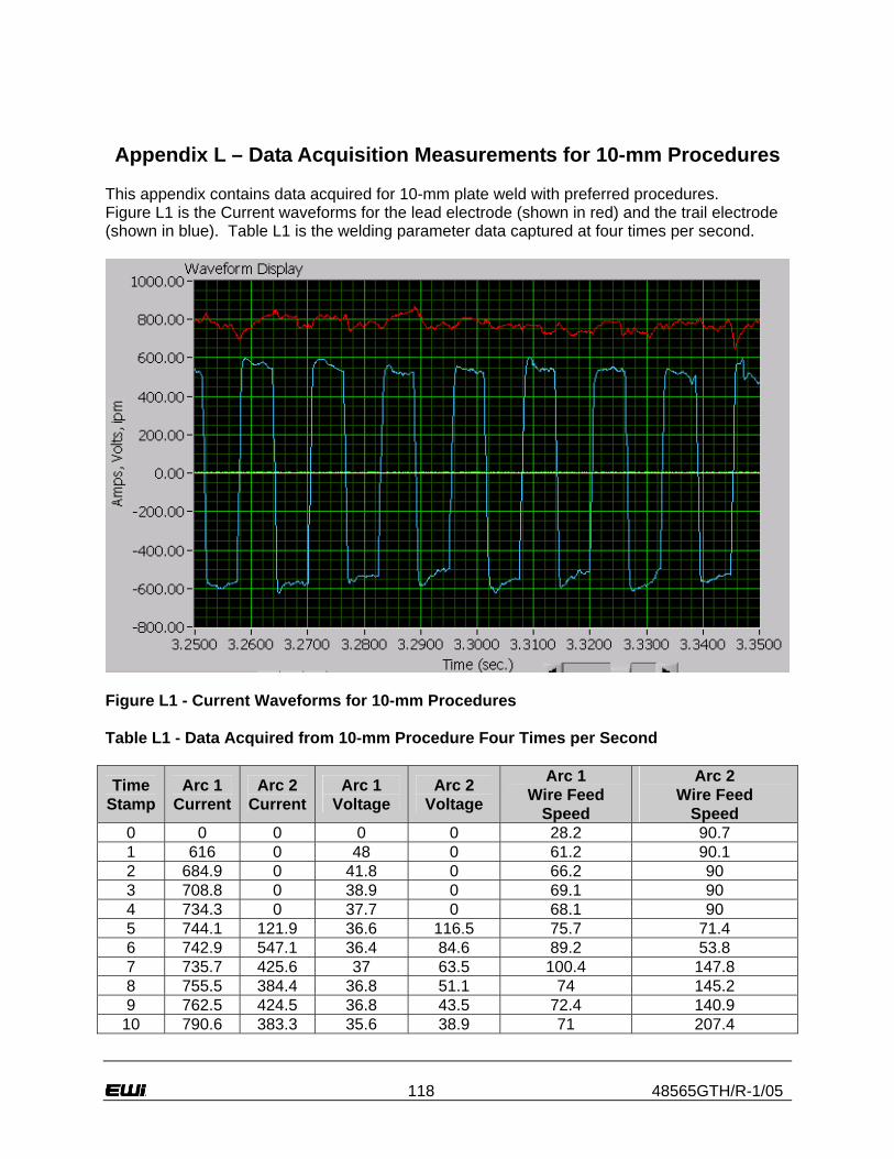
118 48565GTH/R-1/05
Appendix L – Data Acquisition Measurements for 10-mm Procedures
This appendix contains data acquired for 10-mm plate weld with preferred procedures. Figure L1 is the Current waveforms for the lead electrode (shown in red) and the trail electrode (shown in blue). Table L1 is the welding parameter data captured at four times per second.
Figure L1 - Current Waveforms for 10-mm Procedures Table L1 - Data Acquired from 10-mm Procedure Four Times per Second
Time Stamp
Arc 1 Current
Arc 2 Current
Arc 1 Voltage
Arc 2 Voltage
Arc 1 Wire Feed
Speed
Arc 2 Wire Feed
Speed 0 0 0 0 0 28.2 90.7 1 616 0 48 0 61.2 90.1 2 684.9 0 41.8 0 66.2 90 3 708.8 0 38.9 0 69.1 90 4 734.3 0 37.7 0 68.1 90 5 744.1 121.9 36.6 116.5 75.7 71.4 6 742.9 547.1 36.4 84.6 89.2 53.8 7 735.7 425.6 37 63.5 100.4 147.8 8 755.5 384.4 36.8 51.1 74 145.2 9 762.5 424.5 36.8 43.5 72.4 140.9
10 790.6 383.3 35.6 38.9 71 207.4

119 48565GTH/R-1/05
11 820.1 428.1 34.4 38 69.5 165.1 12 817 430.2 34.5 37.9 71 177.7 13 811 436.8 34.8 37.7 70.7 200.4 14 800.9 498.9 34.9 36.7 71.6 158.8 15 809.2 483.1 34.5 36.4 71.6 147.6 16 803.9 481.1 34.5 36.7 70.8 179.3 17 805.4 496.3 34.5 36.3 71.5 143.4 18 817.3 489.8 34.2 36.3 70.6 156 19 821.2 486.6 33.8 36.4 70.4 157.4 20 822 504 33.7 35.9 69.6 156.3 21 804 495.5 34.1 36.3 71 155.4 22 799.9 491.2 34.5 36.7 71.8 162.1 23 804.7 494.6 34.3 36.7 71.6 158.6 24 820.1 495.5 33.8 36.7 71.3 177.4 25 812.9 494.3 33.9 36.6 70.9 182.3 26 814.8 472.4 34 36.9 70.9 173.4 27 815.6 486.3 33.4 36.9 69.3 172.3 28 810.8 514.8 33.6 36.7 70.3 177.4 29 812.6 515 33.6 36.8 69.8 157.7 30 806.4 489.9 33.7 36.9 70 183.1 31 799.8 512.7 33.6 36.3 70.8 164.4 32 807.4 518.2 33.4 36.1 69.8 176.4 33 807 507.2 33.5 36.1 68.9 165.6 34 803.6 518.1 33.4 35.8 68.6 127.8 35 793.1 488.6 34 36.5 71.3 165.7 36 804.3 495.2 34 36.8 69.3 192.7 37 804.6 520.4 34 36 69.2 159.6 38 804.9 518.8 33.8 36.1 70 169.8 39 813.4 511.1 33.5 36.1 68.2 167.8 40 811.1 505.8 33.3 35.9 69.1 171.9 41 803.1 509.1 33.8 35.8 71.6 169.4 42 783.1 499.1 34.5 36.1 71.3 172 43 794.5 502.3 34.4 36.1 69.8 172.7 44 800.4 497.6 34.4 35.7 71.1 135 45 798.7 487.4 34.4 36.3 67.9 199.2 46 786.2 503 34.4 35.5 70.6 178 47 801.6 512.7 33.8 35.4 71 175.6 48 802.4 475.7 33.8 36.8 70.4 144.1 49 801.3 512.1 33.4 36.4 69.4 187.2 50 808.3 487.2 33.2 36.7 69.9 188.1 51 813 474.5 33.1 38 69.2 221 52 808 515.6 33.4 36.6 69.8 198.2 53 808.5 503.6 34.2 36.2 71 181.2 54 804.3 521.5 34.2 35.7 69.7 177.5 55 784.7 518.4 34.8 35.9 71.2 174.3 56 787.4 507.7 34.7 35.6 70.6 174.6 57 806.1 501.7 33.8 35.5 69.8 180.2 58 801.6 506.5 33.8 36 68.8 186

120 48565GTH/R-1/05
59 815 519.5 33.5 35.3 70.3 171.5 60 813 508.8 33.5 35.2 69.9 172 61 801.6 520.9 34 34.8 69.8 178.3 62 790.7 512.4 34.1 34.8 70.2 179 63 800 511.8 33.7 34.5 68.8 178.7 64 793.7 485.9 34.1 35.4 69.7 186.5 65 813.9 518.3 33.4 34.6 68.9 171.7 66 794.7 498.4 34.2 34.8 70.8 180.8 67 798.8 520.1 33.9 34.3 70.4 176.6 68 815.8 511.5 33.6 34.4 68.4 179.7 69 812.1 508.3 33.7 35.2 70.4 184.4 70 797.2 484.4 33.7 35.1 68.8 178.4 71 792.6 508 33.9 34.7 69.8 178.5 72 795.5 499.2 33.8 34.4 69.6 183.1 73 783 491.3 34 34.6 68.2 181.7 74 785.6 509.1 34.2 34.2 70.2 177.4 75 791.9 500.8 34.6 33.9 69.9 181.4 76 790.1 514.9 34.4 33.5 69.5 179.6 77 796.7 480.9 34.3 34.2 70.1 184.2 78 807 507 33.9 33.8 69.9 180.4 79 804.2 515 33.8 33.3 69.7 176.3 80 803.2 504.7 33.7 33.4 68.4 177.2 81 791.1 525.1 34.1 32.8 69.8 171.7 82 795.4 525.1 34.2 33.3 69.8 174 83 797.2 480.8 33.8 34.3 70.2 180.1 84 796.3 489.4 33.7 33.9 70.4 178.3 85 793.9 516.8 34 33.4 70.1 179 86 804.9 504.1 33.4 33.4 70.1 175.8 87 803.7 506.7 33.4 33.6 69.3 180.1 88 815.6 528.4 33.7 33.3 67.6 137.5 89 805.7 485.2 33.8 34.5 69.8 172.1 90 799.3 480.4 34.1 35.2 70.5 186.8 91 803.3 492.6 34.1 35.1 69.3 176.8 92 798.5 507.8 33.5 33.9 69.2 177.7 93 808.1 496.5 33.2 34 69.2 184.6 94 806.8 497.7 33.4 33.9 68.5 183.6 95 806 503.1 33.4 34.1 69.5 178.8 96 781.9 509.9 34.1 33.7 70.1 177.9 97 792.4 524 34 33.3 69.8 175.8 98 812.7 521.7 33.6 33.1 69.5 175 99 803.2 504.1 33.8 33.3 69.6 176.9
100 795.7 506.8 33.9 33.6 68.7 175.7 101 793.2 506.2 34.1 33.5 69.7 175.1 102 796.6 512.3 34.2 32.9 68.8 172.2 103 797.9 500.5 34.1 33.3 69.2 175.8 104 797.6 505.3 33.9 33 68.6 174.4 105 802.2 502.7 33.4 33.2 68.6 173.8 106 811.1 501.1 32.9 33.2 64.3 174.1

121 48565GTH/R-1/05
107 805.9 499.9 33.6 33.2 68.8 174 108 808.7 481 33.5 34.1 68 176.1 109 808.7 490.6 33.1 33.6 68.3 174.9 110 806.2 494.9 33.6 33.9 69.2 177.5 111 804.1 504.1 33.4 33.6 69.1 173.8 112 792.5 501.3 34.1 33.5 68.9 173.4 113 784.9 478.1 34.1 34 67.6 172.2 114 794.4 515.2 34.2 33.4 69 174 115 809.1 495.6 34 33.7 67.5 194.2 116 801 504.6 34 33.6 68.9 166.6 117 796.1 495.2 34.2 33.8 69.5 174.2 118 799 513.4 34.3 33.5 69.5 173.6 119 812.2 512.5 34.1 33.3 68.6 171 120 818 527.1 33.9 33.2 68.5 168.3 121 813.3 492.4 34 34 68.8 175.7 122 799.2 499.8 34.3 34.1 69.8 176 123 798.6 502.5 34.4 34.1 69.8 173.5 124 799.4 505.1 34.2 33.5 68.2 171.1 125 809.2 500.5 34 33.4 67.8 174 126 804 496.4 34.1 33.4 69.1 175 127 804 498.2 34.1 34.7 69.8 173.8 128 805 489.9 34.2 34.5 69 172.6 129 799.7 494.5 34.4 34.3 70.2 175.4 130 795.6 494.6 34.6 34.2 69.8 175.1 131 805.7 510.1 34.2 33.5 68.8 173.3 132 809.5 522.6 34.1 33.5 68.6 171.7 133 807.8 498.2 34.2 33.9 68.3 176.5 134 814.4 505.9 33.7 33.7 67.7 176 135 809.3 527.6 33.7 33.2 69.5 170.1 136 802.9 501.7 33.6 33.7 70 175.3 137 800.4 526.6 33.9 33.3 69.6 172.4 138 807.9 515.3 33.4 33.4 67.9 174.6 139 805.3 483.8 33.6 34.2 69.3 180.7 140 805 504.3 33.6 33.9 69.3 173.7 141 805.7 494.6 33.5 34.2 69.1 176.3 142 804.6 499.2 33.9 34.3 69.7 175.2 143 805.2 510.4 34 33.4 69.5 171.6 144 803.9 501.6 33.9 33.8 69 173.7 145 792.5 499.5 34 33.8 67.7 174 146 798.3 501.6 33.5 33.6 67.6 173.9 147 789.1 506.3 34 33.4 68.7 173 148 782.4 498.5 34.2 33.4 68.6 177.1 149 791.6 517.9 34 32.9 68.8 170.3 150 798.6 503.1 34.1 33.6 69 173 151 793.2 497.4 34.3 33.8 70 173.8 152 792.9 470.2 34.3 34.4 68.7 185.3 153 788.6 479.6 34.1 34.1 69.2 183.4 154 783.5 489.5 34.2 35 69.2 199.5

122 48565GTH/R-1/05
155 797.1 485.6 34.2 34.9 69.6 136.2 156 789.4 488.4 34.7 34.8 69.7 176 157 799.4 512.4 34.5 34.4 68.6 180.3 158 801.7 496 34.2 34.4 69 179.3 159 806 505.4 33.9 34.2 69.9 176.2 160 812.7 509.5 34 34.7 69.8 174.4 161 798.6 505.7 34.5 34.3 69.7 178.8 162 805.5 518.5 34.1 33.9 69.2 176.2 163 807.7 495.5 34 34.1 69.3 179.2 164 801.7 489.4 33.9 34.7 69.4 182.1 165 801.3 504.9 33.7 34.1 68.6 176.1 166 799.3 505.9 34.2 33.8 69.7 176.6 167 805.2 496.8 34.1 34.2 69 177.6 168 798 495.5 34.4 34.6 62.2 182.6 169 787.8 507.3 34.6 34.2 71.3 174.8 170 788.5 493.2 34.2 34.4 70.7 178.9 171 792.6 511.3 33.8 33.6 69.3 177 172 801.4 503.3 33.8 33.8 69 177.7 173 796.5 509.2 33.8 33.6 69.1 176.3 174 800.6 507 33.6 33.8 69 176 175 792.3 512.2 33.8 33.7 69.9 175.3 176 800.4 507.5 33.7 33.6 68.7 175.4 177 802.9 512 33.5 33.5 69.1 173.7 178 796.8 491.5 33.9 33.8 69.3 177.2 179 799 488 33.9 34.1 69.7 178.3 180 804.9 491.5 33.5 33.9 69.1 178.9 181 801.5 508.2 33.8 33.6 69.7 173.5 182 796.6 497.2 33.9 33.8 69 176 183 800.9 495.5 33.9 33.9 69.6 176.3 184 805.4 480.4 33.7 34 69.4 177.3 185 807.3 496.2 33.5 34.4 68.7 177.4 186 807.8 491.8 33.3 34.2 68.7 176.5 187 809.2 508.6 33.9 34.1 69.2 133.9 188 806.6 465.4 34.3 35.5 66.8 142.8 189 794.6 454.6 34.4 35.9 70.1 188.6 190 799.8 497.9 34.2 35 69.4 168.9 191 808.9 505.8 33.7 34.8 68.7 178.6 192 792.5 496.2 34.2 34.7 69.5 181.3 193 800.7 516.8 33.8 33.9 68.5 178.5 194 806.3 493.3 33.7 34.4 68.8 178.9 195 803.8 505.2 33.8 34.3 68.9 178.9 196 801.9 499.4 34.1 34.2 68.1 182 197 796.6 512.7 34.1 34 69.2 178.4 198 793.1 489.5 34.2 34 69.1 181.7 199 788.9 498.7 34.2 34.2 68.6 182.1 200 797.9 508.5 34.1 33.7 69.6 175.9 201 807.6 524.5 33.9 33.3 69.7 176.1 202 801.7 532.7 34.2 33.3 69.1 172.3

123 48565GTH/R-1/05
203 802.6 492 33.8 34.5 68.4 178.5 204 805.9 508.6 33.9 33.8 69.5 178.9 205 796 424 34 42.6 69.5 163.7 206 793.6 446 33.9 40.3 68.1 176.5 207 788.2 471.4 34.2 39.1 69.3 198.6 208 788.7 494.3 34.7 37.1 71 171.8 209 796.4 504.4 34.2 35 70.2 181.3 210 796.4 511.8 34.3 34.2 69.6 180.8 211 795.3 526.9 34.4 33.2 69.7 178.4 212 804.3 510.3 33.8 33.4 68.8 181.5 213 801.1 519.4 34 32.8 68.8 179.1 214 812.2 512.5 33.9 32.8 68 180.3 215 805.8 506.9 33.9 33.3 69.3 178.4 216 798 504.3 33.7 32.9 69.9 183.2 217 793.8 512.2 33.8 33.3 69.4 182.7 218 801.5 506.3 33.9 33.7 69 184.2 219 789.1 508.1 34.5 33.6 70.6 181 220 794.9 511.7 34.4 33.2 70.8 177.2 221 806.1 515.4 34.1 32.9 71.1 176.9 222 828.4 525.3 32.9 32.5 66.9 175.1 223 827.7 509.4 32.8 32.6 68 175.8 224 808.9 500.1 33.6 32.7 69.3 177.8 225 791.6 503.6 34.3 32.8 70.8 176.5 226 776.6 492.7 35.2 32.9 71.9 176.6 227 782.5 496.6 35.1 33.3 71 175.2 228 793.3 493.8 34.6 33.2 70.1 175.7 229 803.4 496.5 34.3 33.3 69.8 176.2 230 812.5 502.7 33.9 33 68.8 174.6 231 803.1 514.6 33.8 33 68.6 172.7 232 812.7 480.2 33.5 33.6 69.1 178.3 233 807.8 494.1 33.7 33.8 70.6 179.4 234 805.2 501.7 33.7 33.3 70 172.3 235 809.2 493.7 33.9 33.4 69.7 175.2 236 802 494.5 34 33.5 69.4 176.9 237 802 483.6 34 34.1 69.1 179.3 238 807.2 503.7 33.7 33.5 68 175.5 239 793.8 489 34.2 33.6 70.4 174.1 240 802.2 491.4 33.7 33.6 69.4 168.6 241 807.6 488.5 33.5 33.5 67.5 176 242 829.4 505.9 33.4 33.5 63.4 179.1 243 805.8 485.1 34 34 70.5 174.3 244 789.3 490.1 34.5 33.8 69.2 175.5 245 794 496.4 34.3 33.8 70.6 175.5 246 795.8 468.6 34.2 34.6 68.7 186.7 247 793.5 476.5 33.8 35 68.2 187 248 806.8 486.7 33.4 34.4 69.9 187.6 249 801.8 509.2 33.8 33.9 69.8 178.3 250 796.3 503.6 33.9 34.2 69.7 180.4

124 48565GTH/R-1/05
251 806.2 489.5 33.7 34.5 68.7 182.6 252 790.9 487.2 34.3 34.7 70.5 188.1 253 802 490 34 35.1 69.7 180.6 254 831.6 481.4 32.5 35 57 203.4 255 821.9 514.3 32.4 34.1 66.4 167.2 256 809.1 520.8 32.7 33.9 67.2 178.3 257 799.8 517.9 33.2 33.8 67.6 178.1 258 789.2 515.8 33.3 33.7 67.7 175.3 259 790.3 512.8 33.6 33.4 67.8 175.8 260 792.2 516.9 33.4 33.3 67.5 173.8 261 799.4 492.8 33 33.8 67.2 177.2 262 797.9 507.6 33.2 33.6 67.2 176.7 263 795.1 501.8 33.3 33.6 67.3 176.2 264 801.4 509 33.1 33.4 66.9 173.5 265 797.2 498.5 33.4 33.5 66.7 177.3 266 795.5 497 33.4 33.7 66.8 175.2 267 800.8 515.2 33.4 33.2 66.4 173 268 807.5 507.9 33.2 33.4 66.6 172.3 269 797.9 515 31.1 34.1 66.1 0 270 731.6 456.8 31.1 36.7 44.9 65.3 271 660 0 30.9 0 44.7 0 272 648.9 0 32.3 0 0 0 273 644.6 0 35.9 0 0 0 274 0 0 0 0 0 0 275 0 0 0 0 0 0 276 0 0 0 0 0 0 277 0 0 0 0 0 0 278 0 0 0 0 0 0

125 48565GTH/R-1/05
Appendix M – Thick Section Welding with Developed Procedures
At the request of NGNN, EWI attempted to weld 1-in. thick steel plates using the developed tandem SAW procedures. A butt joint configuration with each plate having a 45° bevel and a 5.5-mm root face was used. Root opening (gap) between the two plates was 3.0-mm. The preferred procedure developed for the 8-mm plate thickness was used (Table M1). The resulting weld macrograph is shown in Figure M1. The bead profile was very nice, with complete penetration, good wetting into the joint, and consistent root bead reinforcement height. Future 1-in. thick butt joints may benefit from a reduced bevel angle joint design. Table M1 - Parameters for 1-in. Plate (Same as 8-mm Preferred Procedures)
WELD Plate Root Face Root Wire TRAVEL Combined Lead Trail DATAID Thickness and Opening Separation SPEED Heat Input WFS WFS ACQ
(mm) Bevel Angle (mm) (in.) (ipm) (kJ/inch) (ipm) (ipm) FILENAME
1 inch 5.5mm, 45° 2.9 0.78 35.0 72.9 62 175 _11-07-05_16.27.24.txt
Wire Dia Trav. Angle Tip-to-Work Waveform, RMS Current VOLT(in.) (degr.) (in.) %EP, DCOffst SETPOINT SETPOINT0.15625 0 1.25 CC DC+ 750 34
Wire Dia Trav. Angle Tip-to-Work Waveform, RMS Current VOLT(in.) (degr.) (in.) %EP, DCOffst SETPOINT SETPOINT
0.09375 12 1.250
CC sq, bal=50%, DCOffs=0 500 34
F01
-------------------------------LEADING WIRE PARAMETERS--------------------------------
-----------------------------TRAILING WIRE PARAMETERS-----------------------------
Figure M1 - Macrograph of Weld on 1-in. Thick Butt Joint

126 48565GTH/R-1/05
Appendix N – Project Results Presentation

127 48565GTH/R-1/05

128 48565GTH/R-1/05

129 48565GTH/R-1/05

130 48565GTH/R-1/05

131 48565GTH/R-1/05

132 48565GTH/R-1/05

133 48565GTH/R-1/05

134 48565GTH/R-1/05
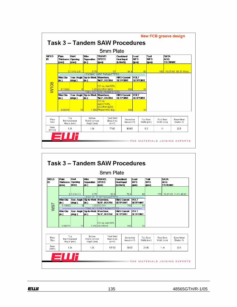
135 48565GTH/R-1/05

136 48565GTH/R-1/05

137 48565GTH/R-1/05

138 48565GTH/R-1/05

139 48565GTH/R-1/05

140 48565GTH/R-1/05

141 48565GTH/R-1/05
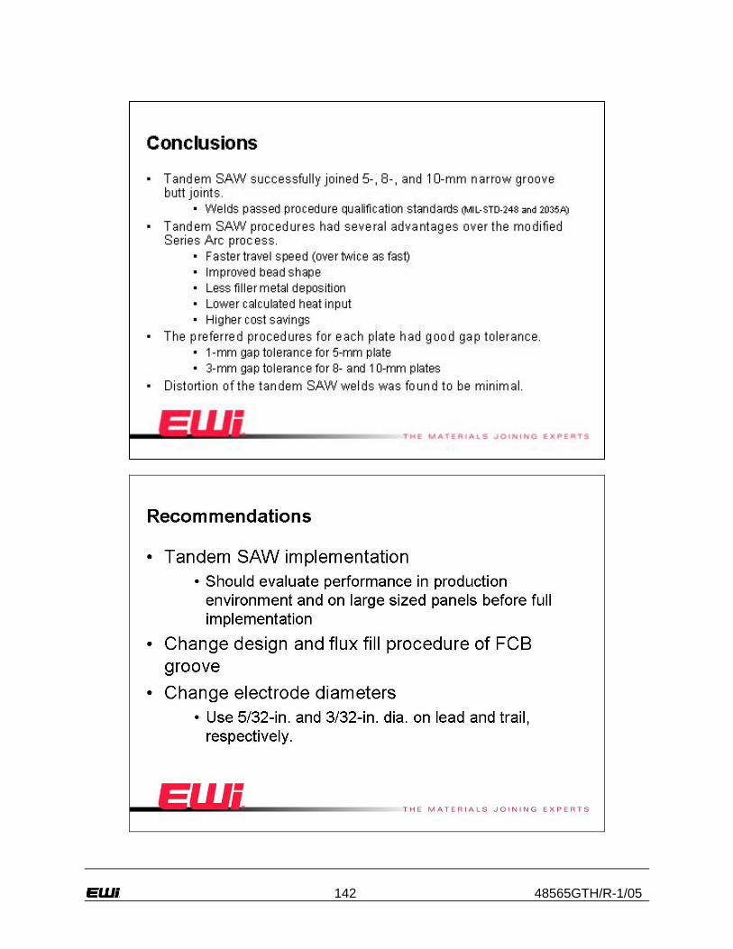
142 48565GTH/R-1/05