
High Risk Construction Oversight Study - Report - NYC.gov
560
Report for Buildings Commissioner Robert D. LiMandri CTL, PC Project No. 500108 High Risk Construction Oversight Study June 5, 2009 Submitted by: Steven J. Smith, Ph.D., P.E. W. Gene Corley, Ph.D., P.E. COA # 0004760 5400 Old Orchard Road Skokie, Illinois 60077-1030 (847) 966-0764 9030 Red Branch Road, Suite 110 Columbia, Maryland 21045 140A Metro Park Rochester, New York 14623 www.CTLPC.com IN NORTH CAROLINA, d/b/a CONSTRUCTION TECHNOLOGY ENGINEERS & CONSULTANTS, P.C.
Transcript of High Risk Construction Oversight Study - Report - NYC.gov

Report for Buildings Commissioner Robert D. LiMandri CTL, PC Project No. 500108 High Risk Construction Oversight Study June 5, 2009 Submitted by: Steven J. Smith, Ph.D., P.E. W. Gene Corley, Ph.D., P.E. COA # 0004760 5400 Old Orchard Road Skokie, Illinois 60077-1030 (847) 966-0764 9030 Red Branch Road, Suite 110 Columbia, Maryland 21045 140A Metro Park Rochester, New York 14623 www.CTLPC.com
IN NORTH CAROLINA, d/b/a CONSTRUCTION TECHNOLOGY ENGINEERS & CONSULTANTS, P.C.
Department of Buildings
City agrees that the scope of work under this Agreement generally involves study of City operations and reporting to the City of findings, observations, some of which will be on a construction work-site, and/or recommendations utilizing engineering judgment and other judgment, including construction industry judgment upon procedures and means and methods of construction as strictly set out in the Request for Proposal for this Agreement. City agrees that the results of the report prepared by Contractor are for informational use of the City and that the report, or portions thereof, may be made available to the public, that there is no intended third party beneficiary of the opinions set out in the report and that others are not entitled to rely on the opinions set out therein; that the City will use its own independent judgment and expertise to decide which and in what manner the opinions set out in the report are to be used for its own benefit and/or published. City agrees that a caveat to this intent may be published by Contractor as a part of the report to serve as notice to all third parties, and City agrees to add this caveat to any material it publishes.

TABLE OF CONTENTS
Page
A. Executive Summary
A.1 Introduction A-1
A.2 Description of the HRCO Study A-2
A.3 Statistical Aspects of the HRCO Study A-5
A.4 Industry Outreach A-8
A.5 Summary of Recommendations A-10
B. High-rise Concrete
B. 1 Introduction B-1
B.2 Site Observations B-3
B.3 Summary of Additional Assessments and Observations B-5
B.3.1 Comparative Concrete Testing B-5 B.3.2 Laboratory Quality Observation B-5 B.3.3 Union Training Facility B-5
B.4 DOB Process Review B-7
B.5 Summary of Recommendations B-8
B.5.1 Formwork B-8 B.5.2 General Site Safety B-9 B.5.3 Worker Falls B-10 B.5.4 Special Inspections and Construction Quality B-10 B.5.5 Plan Review B-11
B.6 Formwork Issues B-12
B.6.1 Description B-12 B.6.2 Design Requirements B-18 B.6.3 Protection of Existing Construction B-19 B.6.4 Formwork Inspection B-20 B.6.5 Lateral and Wind Load Design B-29 B.6.6 Formwork Construction for Wind Resistance B-33 B.6.7 Wind Monitoring (Further Study) B-35 B.6.8 Wind Tunnel Studies (Further Study) B-35 B.6.9 Additional HRCO Data B-36
B.7 Site Safety B-40
B.7.1 Description B-40 B.7.2 DOB Inspector Qualifications B-43
B.7.3 DOB Inspection Procedures B-44 B.7.4 Housekeeping Requirements B-48
B.7.5 Site Safety Hierarchy (Further Study) B-50 B.7.6 Upgrading Netting Requirements (Further Study) B-52 B.7.7 Material Handling B-55 B.7.8 Additional HRCO Data B-59
B.8 Worker Falls B-71
B.8.1 Description B-71 B.8.2 Fall Hazard Awareness B-74 B.8.3 Contractor Documentation (Further Study) B-76 B.8.4 Repeat Offense Enforcement (Further Study) B-76
B.9 Special Inspection and Construction Quality B-80
B.9.1 Description B-80 B.9.2 Special Inspection Rule B-81 B.9.3 Field Inspections B-85 B.9.4 Inspection of Testing Labs B-86 B.9.5 Reinforcing Bend Quality Assurance B-87 B.9.6 Reinforcing Placement Quality Assurance B-89 B.9.7 Additional HRCO Data B-93 B.9.8 Impact of Construction Quality Deficiencies B-95
B.10 Plan Review B-99
B.10.1 Description B-99 B.10.2 Monitoring of Peer Review B-100 B.10.3 Structural Information Quality B-101 B.10.4 Monitoring of Structural Information Quality B-102 B.10.5 Monitoring Constructability B-102
Appendix B.1 Site Observation Log B-106 Appendix B.2 Comparative Concrete Testing B-133 Appendix B.3 Laboratory Quality Observations B-150
C. Cranes and Hoists
C.1 Introduction C-1
C.2 Aspects of Crane Safety C-3
C.3 Site Observations C-7
C.4 DOB Process Review and Industry Outreach C-9
C.5 Summary of Recommendations C-10

C.6 Equipment Design C-13
C.6.1 Description C-13 C.6.2 Approved Manufacturer C-14 C.6.3 Older Equipment C-25 C.6.4 Electric Tower Cranes C-36 C.6.5 Hoist Equipment Acceptance C-38
C.7 Site Specific Design C-40
C.7.1 Description C-40 C.7.2 Tie-ins C-41 C.7.3 Foundations C-51 C.7.4 Load Test C-59 C.7.5 Counter Weights C-62 C 7.6 Crane Design for Wind Effects C-67 C.7.7 PE Sign Off C-68
C.8 Crane Operations C-70
C.8.1 Introduction C-70 C.8.2 Rigging Safety C-71 C.8.3 Articulating Boom Cranes C-83 C.8.4 Crane Assembly C-94 C.8.5 HMO C Licensure C-101 C 8.6 HMO A and B Licensure C-102 C.8.7 Scaffolding Hoist C-108 C.8.8 Riding on Top of Cars C-112
C.9 Inspection C-116
C.9.1 Description C-116 C.9.2 Third Party Inspection C-117 C.9.3 Bolted Connections C-126 C.9.4 Tracking Mobile Cranes C-140 C.9.5 ANSI Standards C-144 C.9.6 Qualified Inspections C-146
C.10 Maintenance and Repair C-152
C.10.1 Description C-152 C.10.2 Maintenance and Repair C-153
C.10.3 Component Tracking C-164 C.10.4 Data Recorder C-173
C.10.5 Off-site Controls C-177 C.10.6 On-site Log Book C-184
C.11 DOB Operations C-188
C.11.1 Description C-188 C.11.2 Inspector and Examiner Training C-189
C.11.3 Accident Investigation C-195 C.11.4 DOB Self Auditing C-199

C.11.5 RS 19-2 Revisions C-203 C.11.6 Hoist Regulation (Further Study) C-204
D. Excavations
D.1 Introduction D-1
D.2 Site Observations D-2
D.2.1 Team Organization D-2 D.2.2 Site Selection D-2 D.2.3 Observation Protocol D-3
D.2.4 Data Collection D-4
D.3 Investigation Results D-5
D.3.1 Design D-5 D.3.2 Methods of Construction D-7 D.3.3 Performance D-10
D.4 DOB Process Review D-14 D.5 Existing Reference Regulation D-15
D.5.1 British Party Wall Act D-15 D.5.2 DIN 4123 D-18
D.6 Summary of Recommendations D-19
D.7 Excavations at Footings D-22
D.8 Limitation on Underpinning D-27
D.9 Preconstruction Surveys D-33
D.10 Monitoring During Excavations D-36
D.11 Minimum Drawing Standards D-43
D.12 Limited Technical Review D-48
D.13 Underpinning Notification D-51
D.14 TR1 and Inspection Log D-54
D.15 Pre-construction Meeting D-59
D.16 State of Practice D-61
D.16.1 Excavations D-63 D.16.2 Earth Retention D-66
D.16.3 Underpinning D-71

D.17 References D-75
Appendix I Benchmarking
I.1 Introduction I-1
I.2 Summary of General Trends and Observations I-3
I.3 HRCO Benchmarking Data Observations I-6
I.3.1 Structural Plan Review Practices I-6 I.3.2 Excavation and Underpinning Practices I-8 I.3.3 Special Inspection and Structural Inspection Practices I-10 I.3.4 High Rise Concrete Forming and Rebar Practices I-12 I.3.5 High Rise Concrete Regulatory and Safety Practices I-14 I.3.6 Crane Practices I-19 I.3.7 Construction Hoist Practices I-22 I.3.8 Regulation and Licensing Practices I-23
I.4 Benchmarking Discussion I-24
Appendix II Principal Staff Resumes


NYC Department of Buildings - High Risk Construction Oversight (HRCO)
Executive Summary A-1
A. Executive Summary A.1 INTRODUCTION This report provides a compilation of findings and recommendations from the New York City Department of Buildings High Risk Construction Oversight (HRCO) study that was conducted from July 2008 through January 2009.
This chapter provides an overview of the study with a discussion of overall purpose and approach. At the end is a summary of the recommendations that resulted from the study.
Following chapters discuss results from the HRCO benchmarking study and general recommendations that apply broadly to New York City construction operations. The balance of the report is devoted to the specific studies and recommendations for high-rise concrete, crane and excavation operations. The chapters on each of these operational areas reflect the specific characteristics of that area of study. Thus, while there is a general similarity among these chapters, there are also many differences in presentation that are necessitated by the differences in the approach and findings in each area.

NYC Department of Buildings - High Risk Construction Oversight (HRCO)
Executive Summary A-2
A.2 DESCRIPTION OF THE HRCO STUDY In July 2008, The New York City Department of Buildings (DOB) initiated the High Risk Construction Oversight study (HRCO). This was precipitated by the March 15th and May 30th fatal crane collapses as well as a general increasing trend in occurrences of job-site accidents. DOB identified three high risk areas of study based on historical accident data: high-rise concrete, cranes and hoists, and excavation operations.
The goal of this study was to develop recommendations for modifications to the NYC regulatory framework and construction industry practices to improve safety. DOB retained CTL as the lead consultant on this effort. CTL partnered with organizations specializing specific to the high risk operations: Crane Tech Solutions (CTS), AECOM, Patuxent Engineering Group, Construction Safety Consultants and DBR Group.
The HRCO study was divided into five areas: high-rise concrete, cranes, excavations, personnel and material hoists, and the Department’s regulatory framework. High-rise concrete comprised buildings greater than 15 stories, which reflects the 1968 building code definition. However, the recommendations are intended to apply to buildings greater than 10 stories, which is the high-rise definition in the 2008 building code.
The HRCO study included:
Site Observations: Systematic review of procedures on construction sites associated with high-risk operations.
Review of DOB Operations: Study of DOB’s regulatory framework, permitting procedures, field inspections and staffing.
Industry Outreach: Site observation teams gathered feedback from construction crews at the selected construction sites on industry and DOB issues and conducted formal meetings with industry.
Benchmarking: Review of procedures and requirements of other jurisdictions.
The purpose of these activities was to identify patterns in the construction process associated with opportunities to improve safety. Thus, for example, site visits and permitting reviews were conducted to identify occurrences of safety issues common to multiple projects rather than exhaustively study safety aspects of any one specific construction project. A formal protocol was established at the onsite of the study by which HRCO field teams alerted DOB of potential safety issues for DOB response and enforcement as necessary.
Each operational team (high-rise concrete, cranes, excavations and hoists) included a principal and a field manager. The team principal was responsible for overall technical execution of the assessment of the operational area. The team field manager was

NYC Department of Buildings - High Risk Construction Oversight (HRCO)
Executive Summary A-3
responsible for oversight of the day-to-day operations of the site observation teams, including assessment of DOB operations. The lead staff for the HRCO study are shown in Table A.1.
Table A.1: HRCO consulting team organization and lead staff.
Project Management: CTL
Steven Smith, Ph.D., P.E. Program Director
W. Gene Corley, Ph.D., P.E. Senior Program Advisor
High-Rise Concrete: CTL
Jeffrey Garrett, Ph.D., S.E. Principal
David Drengenberg, P.E1. Field Manager
Cranes: Crane Tech Solutions (CTS)
Manfred Kohler, D. Eng.
Frank Hegan
Principals
Marcus Janik, D. Eng. Field Manager
Excavations: AECOM
Ted Bushell, P.E. 1 Principal
Darren Diehm, P.E. 1 Field Manager
Hoists: Patuxent Engineering Group
John O’Connor, P.E. 1 Principal
Brian O’Connor Field Manager
Site Safety: Construction Safety Consultants
Larry Naro Principal
Regulatory Operations: DBR Group
Dennis Richardson, P.E. 1 Principal 1Registered in a state other than New York
The participating firms of the study provided expertise in each of the high-risk areas. CTL staff investigated some of the most important construction accidents and failures of recent history, and are leaders in concrete building construction. For example, CTL senior advisor, W. Gene Corley, served as the Team Leader for the FEMA study of the World Trade Center attacks. The excavation team (STS/AECOM) provides excavation consulting services on some of the most challenging projects around the world, including record-setting high-rises such as the Chicago Spire. Crane Tech Solutions has decades of experience in crane design, inspection, maintenance and leasing services. Patuxent Engineering Group is one of only a handful of firms providing consulting expertise in temporary structures including construction hoists. DBR Group provided experience to critically assess the NYC regulatory framework. DBR Group

NYC Department of Buildings - High Risk Construction Oversight (HRCO)
Executive Summary A-4
principal, Dennis Richardson, is a past building official and active member of building code committees.
In all, a staff of more than thirty experts participated in the study. Most principals are presidents and CEOs with decades of experience in their respective fields. The HRCO experts have practiced throughout the United States, both in New York City and outside. The teams’ broad geographical range of experience provided a useful perspective to compare and contrast New York City construction practices with those prevailing in other dense urban areas that face similar public safety challenges.

NYC Department of Buildings - High Risk Construction Oversight (HRCO)
Executive Summary A-5
A.3 STATISTICAL ASPECTS OF THE HRCO STUDY The HRCO study utilized statistical procedures to the greatest extent possible. Table A.2 provides a summary of historical DOB data related to construction operations. Incidents include any event at a job site that required DOB response and accidents are those incidents that caused injury, fatality or significant property damage. The high risk columns provide subtotals for high-rise concrete, cranes, excavations and hoists. As can be seen, the operations identified as high risk account for approximately 1/3 of accidents and ½ of fatalities. Additionally, the rate of injuries and fatalities per accident is typically higher for these four types of operations.
High-rise Concrete
Cranes Excavation Hoists High Risk
All Other
Total High Risk %
Incidents 141 73 138 39 391 878 1269 31%
Accidents 63 23 19 18 123 246 369 33%
Injuries 68 52 22 31 173 269 442 39%
Fatalities 6 12 2 6 26 24 50 52%
Table A.2: HRCO review of DOB incident database (data from January 2, 2006 to January 13, 2009)
Statistical aspects for each operational area are discussed in those chapters of this report. In general it must be recognized that the HRCO study, while substantial and methodical, was still limited to a relatively brief period of time (August – December, 2008) and a limited cross section of the NYC construction environment. Additionally, accidents associated with construction are generally indeterministic (random events that cannot be predicted with certainty) and are a function of human factors, materials, and equipment. In many instances the study relied on extrapolation and empirical assessment of observations. Results are based on the most well-considered assessment possible utilizing limited and variable data combined with the professional experience of the team and input from DOB and Industry.
The method used to preliminarily assess viability of the study is as outlined in ASTM E122 - Standard Practice for Calculating Sample to Estimate, With a Specified Tolerable Error, the Average for a Characteristic of a Lot or Process. This procedure provides a basis for determining meaningful sample sizes for indeterminate processes such as NYC construction operations. Table A.3 provides examples of sample size calculations.

NYC Department of Buildings - High Risk Construction Oversight (HRCO)
Executive Summary A-6
Table A.3: Sample Size Calculations per ASTM E122.
Population probability
0.05 0.10 0.30
Error in estimating population probability
0.10 0.10 0.10
Probability of exceeding error
0.05 0.05 0.05
Minimum sample size
18 35 81
The interpretation of Table A.3 is as follows:
1. Population probability is the rate of occurrence of a specific defect. For example, the percentage of construction sites that might exhibit a fall hazard.
2. Error in estimating population probability, relative to the example above this is the error in estimating the percentage of occurrences of fall hazards. In Table A.3 this is taken uniformly as 10% (thus the actual occurrence of fall hazards would be within 10% of the expected probability).
3. Probability of exceeding error, allows for the potential that the actual error will be greater than specified in item 2.
4. Minimum sample size, based on the acceptable error rates described above, this is the minimum sample size to properly observe the specified defect.
A rigorous application of this method to every facet of the high risk operations is not practical. However, relative to the “defect rates” that were observed in NYC, ASTM E122 indicates that the number of site observations conducted during the HRCO study were of reasonable order to characterize the operations. Summaries of site observation totals and geographical distribution are provided in Table A.4 and Figure A.1. Table A.4: Summary of HRCO Site Observation Totals.
Operational Area Site Observations (includes repeat visits)
Distinct Sites
High-rise Concrete 181 94
Cranes 182 104
Excavations 174 144
Hoists 99 90
Total 636 432

NYC Department of Buildings - High Risk Construction Oversight (HRCO)
Executive Summary A-7
For example, the fall hazard risk of not tying-off was observed at 31% of high-rise concrete sites. Going back to table A.3 shows that approximately 81 site observations would be necessary to properly observe a defect that occurs at this rate, and with the specified error limits. Thus the HRCO total of 181 site safety site visits at 94 unique sites (see High-rise Concrete chapter) should be sufficient to characterize tie-off violation issues.
Figure A.1: Distribution of site observations.
High-rise Concrete
Cranes
Excavation
Hoists

NYC Department of Buildings - High Risk Construction Oversight (HRCO)
Executive Summary A-8
A.4 INDUSTRY OUTREACH
The general approach of engaging industry was similar and two-phased among the operational teams (high-rise concrete, cranes, excavations and hoists). One primary method of industry outreach was accomplished at job sites, by gathering feedback from construction staff. The other method was through formal subcommittee meetings with a cross-section of industry stakeholders.
In addition to these two methods each operational team conducted other forms of outreach as guided by particular aspects of the study (e.g. the high-rise concrete team observed operations at a union training facility). Major industry meetings conducted as part of the study are presented in Table A.5.
Table A.5: HRCO Industry Outreach Meetings.
Operation Areas Date Description
High-rise Concrete and Excavations
Nov. 18, 2008 Kick-off meeting with industry stakeholders.
Dec. 15, 2008 Construction quality meeting.
Dec. 18, 2008 Concrete industry subcommittee meeting #1.
High-rise Concrete
Jan. 20, 2009 Concrete industry subcommittee meeting #2.
Oct. 16, 2008 International crane symposium.
Nov. 7, 2008 Crane industry roundtable.
Dec. 15, 2008 Crane industry subcommittee meeting #1.
Dec. 16, 2008 Crane manufacturer meeting.
Jan. 8, 2009 Crane industry subcommittee meeting #2.
Cranes
Jan. 21, 2009 Crane industry subcommittee meeting #3.
Dec. 18, 2008 Hoist industry subcommittee meeting #1. Hoists
Jan. 13, 2009 Hoist industry subcommittee meeting #2.
Dec. 15, 2008 Excavation industry subcommittee meeting #1. Excavations
Jan. 13, 2009 Excavation industry subcommittee meeting #2.
All Feb. 3, 2009 Buildsafe seminar with breakout sessions for each operational area.
Industry subcommittees were formed by soliciting participation from professionals, and, in the case of cranes, major manufacturers. Each operations group conducted at least two monthly meetings. The first meeting was primarily devoted to presentation of

NYC Department of Buildings - High Risk Construction Oversight (HRCO)
Executive Summary A-9
developing recommendations. Follow up meetings were focused on refining the final recommendations. Relevant source data (as available) and draft summaries were provided in advance of the meetings to industry and DOB. Subcommittee participants were invited to comment on interpretation of the presented data; individual experiences; scope and content of the proposed recommendations; feasibility of implementation; and, perceived effectiveness and anticipated compliance with the potential recommendations. Participants were also encouraged to suggest alternative or supplemental recommendations based on knowledge of local practice and experience with the existing regulatory process. Participating stakeholders are shown in Table A.6.
Table A.6: HRCO Industry Stakeholders.
High-Rise Concrete Cranes and Hoists Excavations
Concrete Industry Board Alimak Hek, Inc. Morrow Equipment Company Bronzino Engineering
Bovis Lend Lease ALL Safe LLC North Side Structure Steel Institute of NY
BTEA
BTEA AMG Engineering Perimeter Bridge & Scaffold Corp.
Desimone Consulting
Casino Development Group Atlantic Hoisting and Scaffold Plan B Engineering Foundations Group
DCP Bay Crane REBNY General Contractors Association of NY
Desimone Consulting BTEA Regional Scaffolding John Civetta & Sons, Inc.
DiFama Concrete Building Contracting Assoc. Rockledge Scaffold LMW Engineering
Flint Lock Construction CAGNY Steel Institute of NY Local 780
Foundations Group Carpenters Local 1536 Stroh Engineering Services Mueser Rutledge
Howard I Shapiro & Associates
Colgate Scaffold Tadano Cranes Pillori Associates
Local 46 Favelle Favco Cranes USA Inc
Terex Cranes Wilmington, Inc. RA Consultants LLC
Narov Assoc/ALEC Howard L. Shapiro & Associates
TES Inc REBNY
North Side Structures Liebherr-Werk Biberach The Cement League Urban Foundation Engineering
Port Authority of NY & NJ Lift Tech Elevator Thyssen Krupp Safeway
REBNY Linkbelt Construction Equipment Company
Tishman
SEAoNY Local 1 United Hoisting & Scaffobling Corp.
Tectonic Engineering Local 14 (Operator's Union) Universal Builders Supply (UBS)
The Cement League Local 46 Metallic Lathers Union
US Dol OSHA
Thornton Tomasetti Manitex Valjato Engineering
Urban Foundation/Eng LLC Manitowoc
US DOL OSHA
WSP Cantor Seinuk

NYC Department of Buildings - High Risk Construction Oversight (HRCO)
Executive Summary A-10
A.5 SUMMARY OF RECOMMENDATIONS The culmination of the HRCO study was development of more than sixty recommendations to improve safety during high-risk construction operations. Separate chapters for each operation detail the development and content of these recommendations. Below is a table summarizing all of the recommendations. The table includes each recommendation name and ID, a paraphrase of the recommendation language, a key observation associated with the recommendation and identification of further study items. The recommendation ID uses HC (high-rise concrete, C (crane), E (excavation) and H (hoist). Further Study recommendations, as the designation implies, are those for which there is clear indication safety improvements are possible, but specific and necessary details of the recommendation require additional study. The key observation provides a single example of the supporting data to provide a degree of context for the recommendation.
Recommendations that are not identified as Further Study may still require analysis or alteration as they are being implemented. And all recommendations, whether or not Further Study, should be subjected to on-going review after implementation to assess whether the desired affect is being achieved.
It is important to appreciate that this study was motivated by construction accidents and had the sole purpose of generating recommendations for changes to construction operations and regulatory practices to improve safety. Thus, by its very nature, the focus of the study was to identify areas in which there is opportunity for significant improvement.
New York City is a dynamic and challenging environment in which to undertake construction. Many of the leading design and construction companies in the world have sole or primary practices in New York City. Thus, the HRCO team did not lightly take on the task of providing these recommendations. In a number of instances the recommendations were generated by observing positive practices that are already in place by many in the industry and recognizing that the practice should be adapted universally.
Lastly, the HRCO team recognizes that a number of recommendations apply beyond the subject operational area. This is particularly relevant, for example, regarding site safety and fall hazard recommendations. These were motivated by high-rise concrete accidents, but similar risks occur with steel and masonry construction. The degree and manner in which recommendations should be applied to other construction operations should be carefully considered as the recommendations are implemented.

NYC Department of Buildings - High Risk Construction Oversight (HRCO)
Executive Summary A-11
High-Rise Concrete - Formwork
HC-1 Formwork Design Requirements Require essential specification information to be included on stamped formwork designs. Key Observation: 45% of critical formwork defects attributable to design.
HC-2 Protection of Existing Construction Require thresholds for the production of stamped and sealed formwork designs to include instances where adjoining structures are used to support formwork. Key Observation: Recent occurrences of concrete construction causing failures in adjoining buildings.
HC-3 Formwork Special Inspection Require Regular special inspection of formwork and reshore installations. Key Observation: 79% of critical formwork defects attributable to construction.
HC-4 Formwork Lateral and Wind Load Design Clarify existing wind design requirements in conformance with national design standards. Key Observation: Five incidents of wind-induced formwork failures since 2006
HC-5 Formwork Construction for Wind Resistance Require formwork decking to be positively secured against uplift. Key Observation: Majority of respondent municipalities utilize wind resistant engineered modular formwork.
HC-6 Wind Monitoring Further Study Require continual monitoring of actual wind conditions. Key Observation: Available remote wind data is not a sufficient surrogate for site-specific conditions.
HC-7 Wind Tunnel Studies Further Study Perform wind tunnel studies to better understand the effect of wind on formwork assemblies. Key Observation: Available references on the subject are limited.

NYC Department of Buildings - High Risk Construction Oversight (HRCO)
Executive Summary A-12
High-Rise Concrete – General Site Safety
HC-8 DOB Inspector Qualifications Augment current DOB inspector training regimens to mirror industry expertise.
Key Observation: Inspector knowledge base regarding safety is critical to credibility of department.
HC-9 DOB Inspection Procedures Update and maintain sets of inspection protocols.
Key Observation: Non-uniform enforcement is the most common industry criticism of Department of Buildings.
HC-10 Housekeeping Requirements Clarify specific housekeeping requirements.
Key Observation: Falling debris is one of the most commonly reported incidents.
HC-11 Site Safety Hierarchy Further Study Remove conflict of interests with respect to site safety personnel. Key Observation: Field observations indicate site safety personnel are hampered by potentially conflicting lines of accountability.
HC-12 Upgrading Netting Requirements Further Study Study Effectiveness of enhancing existing netting requirements. Key Observation: Over 200 material fall incidents reported between January ’06 and June ‘08
HC-13 Material Handling Further Study Establish requirements for the use of outrigger systems for material handling. Key Observation: Current material handling practice creates significant fall hazards at building edges.
High-Rise Concrete – Worker Falls
HC-14 Fall Hazard Awareness Implementation of a fall hazard awareness campaign.
Key Observation: Workers failed to adequately tie off at 31% of visited sites.
HC-15 Contractor Documentation Further Study Require contractor to document remedial actions taken after safety violations.
Key Observation: Worker falls account for 66% of all fatalities on concrete construction sites.
HC-16 Repeat Offense Enforcement Further Study Require mandatory site shut down after reaching a specific violation count threshold.
Key Observation: Statistical analysis indicates existing enforcement practices are not correlated with reduced numbers of safety violations.

NYC Department of Buildings - High Risk Construction Oversight (HRCO)
Executive Summary A-13
High-Rise Concrete – Special Inspections and Construction Quality
HC-17 Special Inspection Rule Enforce that all special inspectors conform to updated NYC code requirements.
Key Observation: Construction quality violations were documented at more than half of all visited sites.
HC-18 Field Inspection Enhance inspector training to include construction quality issues such as field testing of concrete.
Key Observation: Current inspector expertise does not include construction quality issues.
HC-19 Inspection of Testing Labs Enhance DOB staff training to include laboratory testing procedures and requirements.
Key Observation: Testing laboratory observations indicated pervasive non-conformance with code requirements.
HC-20 Reinforcing Bend Quality Assurance Require documentation of proper bar bending procedures. Key Observation: Critical construction quality issues were observed at a quarter of all visited sites. Improper bar bending procedures are a significant contributor to this defect rate.
HC-21 Reinforcing Placement Quality Assurance Require documentation of proper bar placement procedures. Key Observation: Critical construction quality violations were observed at a quarter of all visited sites. Improper bar placement is a significant contributor to this defect rate.
High-Rise Concrete – Plan Review
HC-22 Monitoring of Peer Review Recommend the retention of professional engineers to supervise the peer review process.
Key Observation: Majority of responding municipalities perform detailed structural review.
HC-23 Structural Drawing Information Require minimum levels of structural information to be included on drawings.
Key Observation: Not all sets of structural drawings contain sufficient levels of design information.
HC-24 Monitoring of Structural Information Quality Recommend the retention of professional engineers to review drawings for minimum levels of structural information.
Key Observation: Many responding municipalities utilize engineering staff to review plan submissions for structural issues. HC-25 Monitoring Constructability Recommend the retention of professional engineers to review drawings for constructability.
Key Observation: Many responding municipalities utilize engineering staff to review plan submissions for structural issues.

NYC Department of Buildings - High Risk Construction Oversight (HRCO)
Executive Summary A-14
Excavations
E-1 Excavations at Footings Requirements for Excavations at Footings to Protect Adjacent Structures. Key Observation: Standard geotechnical practice that is not enforced in NYC by code or convention.
E-2 Permitting of Underpinning Revisions to underpinning permitting to better screen for safety issues. Key Observation: Nearly 88% of jurisdictions stated that a detailed or partial technical review was performed on permit applications for permanent systems. The recommendation is intended to provide a sorting mechanism to allow DOB to prioritize the most technically challenging submittals for review.
E-3 Preconstruction Surveys Preconstruction survey requirements to better define condition of neighboring structures. Key Observation: 18% of Contractors (or Site Contacts) could not verify that a preconstruction survey was performed prior to construction. Of those that responded that a survey was done, only one could produce a copy of the assessment report for HRCO review.
E-4 Monitoring During Excavations Requirements to better monitor the effect of excavation operations on neighboring structures.. Key Observation: 21% of the sites had damage to adjacent structures (settlement or visibly discernable distress) which could be attributed to earth retention and/or underpinning operations
E-5 Minimum Drawing Standards Recommendations for minimum content on design submittals to sufficiently convey critical information. Key Observation: Inadequacies (ranging from minor elevation issues to potentially un-constructible details) were identified in approximately 46% of the drawings available for review by the HRCO
E-6 Limited Technical Review Require pre-permit technical review of excavation design. Key Observation: The current Department of Buildings practice of submittal reviews based on fire, egress, and zoning will not capture technical deficiencies or incomplete subgrade site designs.
E-7 Underpinning Notification Require advanced notice of underpinning operations to DOB to improve inspection rates Key Observation: Based on the available permit filing data, active sites (defined as a contractor on-site and available access) were identified by the HRCO at a rate of 40 to 45% - active underpinning was observed at only 11 sites.
E-8 TR1 and Inspection Log Enhancements for TR1 and inspection logs to improve oversight and accountability Key Observation: Inadequate construction or variation from permitted design was identified at approximately 36% of sites with earth retention systems and 26% of sites with underpinning.
E-9 On-Site Meetings Preconstruction onsite meeting with contractor, designer and special inspector to improve coordination. Key Observation: 35% of the Contractors (or other Site Contacts) could not identify the Special Inspector. Of those that could identify the Special Inspector, less than 50% could provide the date of the last site visit.

NYC Department of Buildings - High Risk Construction Oversight (HRCO)
Executive Summary A-15
Crane – Equipment Design
C-7 Approved Manufacturer Replace the current model-specific Certificate of Approval process with one that approves the manufacturer using predetermined, industry-standard criteria. Key Observation: Reviewing designs of modern cranes is not feasible.
C-14 Older Equipment Require an extensive mechanical crane inspection every 10 years for all cranes and potentially an age limitation for operation in the jurisdiction.
Key Observation: 41% of tower and 10% of mobile cranes are older than 20 years and 23% of tower and 9% of mobile cranes are older than 30 years.
C-21 Electric Tower Cranes Further Study Have an all-electric tower crane fleet in the jurisdiction by a specified date. Key Observation: Replacing diesel cranes with electric will have many cascading benefits by modernizing the fleet.
H-1 Hoist Equipment Acceptance Further Study Create and implement an Equipment Acceptance Certification program for hoisting equipment employed in the NYC area. Key Observation: There is no current method to restrict the increasing use of “cloned” hoist equipment.

NYC Department of Buildings - High Risk Construction Oversight (HRCO)
Executive Summary A-16
Crane – Site Specific Design
C-8 Tie-Ins Tie-In connections should be subjected to special inspection and require improved design and erection procedures.
Key Observation: 71% of reviewed plans did not have an engineering review of the loads imposed on the building.
C-9 Foundations Foundations should be subjected to special inspection and require improved design and erection procedures.
Key Observation: Foundations are typically poured prior to a plan review by the Cranes and Derricks division making it difficult to determine if the foundation was installed as designed.
C-15 Load Tests The test weights to be used should not exceed the manufacturer’s specification or, in case where the manufacturer is not available, the applicable ANSI standard should be used.
Key Observation: 38% of reviewed load test procedures provided a test that could have overloaded the crane, and DOB inspectors have allowed such occurrences based upon the submitted procedure.
C-5 Counterweights Counterweight information should be readily available on the drawing and on the counterweight module itself. Key Observation: 93% of observed tower cranes did not have all counterweight modules labeled for easy reading and 15% of the movable counter weight mechanism required maintenance.
H-2 PE Sign-Off (Hoists) Require the building engineer of record or an engineer acceptable to DOB to review that the building can support the loads imposed by the hoist. Key Observation: 73% of hoist machines had no indication of an engineering review of loads imposed on the building.

NYC Department of Buildings - High Risk Construction Oversight (HRCO)
Executive Summary A-17
Crane – Crane Operations
C-4 Rigging Safety The city should increase enforcement of current regulations related to rigging practices, eliminate the practice of “side pulling” loads and improve rigger training courses.
Key Observation: Multiple and diverse occurrences of dangerous rigging operations.
C-12 Articulating Boom Crane The definition of “crane” should be changed so that articulating boom cranes are regulated as other cranes.
Key Observation: Five of six cranes observed had issues with set up, rigging and/or operations.
C-13 Crane Erection All assembly, climbing and dismantling of a tower crane must include the on-site participation of a Technical Advisor.
Key Observation: Operational issues identified at 40% of assembly/climbing/disassembly activities.
C - 1 HMO C Licensure Require National Crane Operator Certification for Hoisting Machine Operator “C” License Examination and Evidence of Fitness for Duty
Key Observation: Many major jurisdictions moving to recognized national organizations to provide consistent crane operator certification.
C - 23 HMO A and B Licensure Require all Hoist Machine Operators (HMOs) to have a nationally recognized certificate and ensure each operator has the necessary experience to operate the cranes they use. Key Observation: Many major jurisdictions moving to recognized national organizations to provide consistent crane operator certification.
C - 24 Scaffolding Hoist Further Study DOB should require a plan review and inspection of custom built hoisting systems that are able to hoist loads exceeding 1 ton (907 kg)
Key Observation: These hoists typically are not subject to a plan review or formal inspection.
H - 3 Riding on Top of Cars Further Study Restrict actions of workers riding on top of cars to limit inherent dangers of working on and in close proximity to moving equipment
Key Observation:

NYC Department of Buildings - High Risk Construction Oversight (HRCO)
Executive Summary A-18
Crane – Inspections
C - 3 Third Party Inspection Allow third party inspectors to perform the required annual crane inspections needed for the CD permit.
Key Observation: The use of PLCs, the pressure to innovate their products and niche markets requiring specialized machines increases complexity and requires constant training for crane inspectors.
C – 2 Bolted Connections All bolted connection must be checked regularly. Crane maintenance personnel must have basic knowledge of bolt torquing.
Key Observation: 20% of tested bolts were loose.
C-17 Tracking Mobile Cranes Require DOB notification prior to use of a mobile crane on a job site.
Key Observation: The listed crane is available for inspection on only 10% of job sites.
H - 4 ANSI Standards Adopt the ANSI A10.5 Material Hoist standard. Regularly update regulation to reflect current versions of A10.5 and A10.4 (Personnel Hoist standard). Key Observation: There is no national standard in NYC for material hoists.
H - 5 Qualified Inspections Introduce a “Qualified Hoist Inspection” program that establishes the requirements and qualifications of the inspectors and inspection criteria. Key Observation: Less than 10% of hoists had been properly inspected during required “drop test”.

NYC Department of Buildings - High Risk Construction Oversight (HRCO)
Executive Summary A-19
Crane – Maintenance and Repair
C - 6 Maintenance and Repair The Owner must notify DOB of all major structural repairs. Parts and procedures should meeting manufacturer requirements.
Key Observation: No current method to confirm that crane repairs restore crane to proper working condition.
Increase the written maintenance and inspection log requirements to provide more complete records of the work performed on each crane
Key Observation: 57% of the issues observed on cranes were related to maintenance and repair.
C-20 Component Tracking DOB should institute a tracking system for the major structural components.
Key Observation: There are manufacturers of crane replacement parts that have no authorization or technical support from the original crane designer and manufacturer.
C-22 Data Recorder - “Black Box” Further Study Based upon further study, DOB should consider the use of data recording devices that will provide critical information regarding the operation of cranes within the jurisdiction.
Key Observation: Without such technology neither DOB nor owner knows the actual service demands placed on the crane.
H - 6 Off-site Controls Further Study Introduce and implement an Off-site Hoist Equipment Control Program to check that the equipment is adequate for the intended use.
Key Observation: 30-year old hoist masts had almost 30% loss of thickness due to corrosion and wear.
H - 7 On-Site Log Book Require that all site locations maintain an On-Site Hoist Equipment Log to standardize record keeping of all pertinent data
Key Observation: Less than 20% of sites maintain any type of hoist maintenance or inspection records.

NYC Department of Buildings - High Risk Construction Oversight (HRCO)
Executive Summary A-20
Cranes – Department of Buildings’ Operations
C - 11 Inspector and Examiner Training Assess the various skill sets of the inspectors and plan examiners of the Department of Buildings and provide them the necessary training and tools to complete their tasks effectively and efficiently.
Key Observation: The importance of training (for both DOB and industry workers) was highlighted by almost every stakeholder group as a leading factor of crane safety.
C-18 Accident Investigation The Crane and Derrick Division should augment and audit its incident/accident reporting procedures
Key Observation: Improved accident documentation will provide better basis for assessing trends of safety issues.
C-19 DOB Self Auditing Develop and install a change process whereby the Cranes and Derricks Division of the Department of Buildings monitors itself and makes adjustments as necessary.
Key Observation: The Cranes and Derricks Unit (C&D) underwent a major restructuring in the past year and must now critically assess its accomplishments and areas that require improvement.
C - 16 RS 19-2 Revisions DOB should revise of RS 19-2 and seek industry comments.
Key Observation: The RS19-2 presently does not reference ASME B30.3 and B30.22 standards (the leading US standards for tower cranes and articulating boom cranes)
H-8 Hoist Regulation Further Study Hoist equipment (Personnel and Material Hoists and Back-Structures) should be subjected to engineering review, permitting and site inspection by a dedicated DOB department
Key Observation: There is no centralized and comprehensive approach to hoist regulation.

NYC Department of Buildings - High Risk Construction Oversight (HRCO)
High Rise Concrete B-1
B. High-rise Concrete B.1 INTRODUCTION This chapter summarizes the high-rise concrete construction assessment, and includes this introduction (Section 1), methodologies used to conduct the assessment (Section 2), studies and observations completed in addition to the assessments (Sections 3 and 4), and a summary of the recommendations (Section 5). CTL principally authored this chapter.
The High Risk Construction Oversight (HRCO) Team encountered great interest and desire on the part of the construction industry to increase safety on active construction sites. At the same time, during the observation of day-to-day construction operations throughout New York City, it became clear that there is substantial need for changes in the current construction practices and behaviors to actually achieve an increase in site safety. As with the NYC construction industry’s past efforts to establish an awareness that hard-hats must be worn on construction sites, a program that required a committed long-term campaign, there are many facets of the construction process which will require a targeted, disciplined approach to actually achieve the universally agreed goal of improved safety. This is true of nothing so much as the need to greatly improve the current practice regarding fall protection. In this case there are sufficient regulations in place, but compliance is poor. Penetrating and changing this aspect of construction culture will require resolve by DOB and industry.
A primary theme that became apparent during this assessment is the need for modernization in the construction processes utilized in New York City by contractors. For example, modernization of current formwork practices could improve at least three safety issues: personnel fall hazards; material fall hazards; and, the structural integrity and safety of the formwork. Personnel fall hazards are associated with the labor-intensive nature of formwork construction and stripping, much of it needing to occur near the building edges, and the efforts required to provide effective fall restraints near these edges. Material fall hazards are related to the significant amount of loose material that is kept on the construction floors. Structural integrity is associated with the importance of designing and constructing the formwork to support substantial loads from wet concrete and the challenge of providing proper inspection.
Each of these three safety issues is made more challenging by the wide-spread use of stick-built forms in New York City. By comparison, the overwhelming majority of municipalities surveyed by the HRCO use prefabricated concrete forming systems for major projects1. Prefabricated forms offer advantages of built-in anchorage systems, more efficient control of on-site materials, and more uniform structural integrity. This is not to say that stick-built formwork can not be used safely, but it must be recognized that this outmoded forming system serves more to impede than promote safety.
1 See Formwork Recommendations

NYC Department of Buildings - High Risk Construction Oversight (HRCO)
High Rise Concrete B-2
In similar ways modernization applies to the procedures utilized during construction inspection, concrete reinforcing steel fabrication and placement, documentation of field changes and monitoring of site safety.

NYC Department of Buildings - High Risk Construction Oversight (HRCO)
High Rise Concrete B-3
B.2 SITE OBSERVATION A total of 279 site observations were completed by HRCO field teams between August and November 2008. The two-person observation teams typically consisted of an Engineer and Safety Expert. Targeted site visits were limited to safety issues only. Full site visits included safety and engineering observations. A member of the DOB Building Enforcement Safety Team (BEST) accompanied the HRCO observation teams during a substantial number of site visits.
Sites were selected, and visited randomly, from a list of addresses with permit applications for concrete-framed buildings filed after January 1, 2008, and therefore likely to be actively engaged in construction activity (i.e.; an active site). The entire population of “Major”2 buildings was selected from this list. In addition to these Major buildings, the HRCO observation teams visited the site of a limited number of other buildings3. Site observation data is summarized below. Detailed site observation summaries are provided in Appendix B.1.
Table 1: Active Site Visits4
Targeted Site Visits
(Safety Only) Full Site Visits (Safety
and Engineering)
Total Visits 181 98
Visits by Boro. 145 Manhattan
36 Brooklyn
82 Manhattan
16 Brooklyn
2 At the time of observation, the 1968 NYC Building Code definition was used (structures exceeding 15 stories, heights of 200’, or footprint areas of 100,000 SF).
3 Buildings with fewer than 15 stories
4 Includes multiple random repeat visits at particular addresses

NYC Department of Buildings - High Risk Construction Oversight (HRCO)
High Rise Concrete B-4
Table 2: Distinct Site Observations at Active Sites
Targeted Site Visits
(Safety Only) Full Site Visits (Safety
and Engineering)
Total Number of Distinct Properties
67 59
Visits by Boro. 60 Manhattan
7 Brooklyn
52 Manhattan
7 Brooklyn
Observation procedures included the following.
• A survey of the building site was conducted using a standardized Location Report form. Additional information, gleaned from interviews or observations not directly addressed by the Location Report format, was entered as comments.
• Interviews were conducted with construction staff and site safety personnel
• Photographic documentation of representative safety and quality conditions
• Relaying critical safety and/or construction conditions to the Department of Buildings

NYC Department of Buildings - High Risk Construction Oversight (HRCO)
High Rise Concrete B-5
B.3 SUMMARY OF ADDITIONAL ASSESSMENTS AND OBSERVATIONS Additional observations and assessments were made outside the scope of standard site observation procedures. These additional tasks gauged the accuracy of five selected concrete testing laboratories, assessed the quality of concrete laboratory testing and reporting at three facilities, and assessed the level of rebar fabrication and placement training offered by the Metallic Lathers and Reinforcing Ironworkers Union Local 46, during a visit to their Queens, New York training facility.
B.3.1 Comparative Concrete Testing Concerns were raised regarding the concrete sampling and testing methods typically employed throughout the City. Specifically, the ability of testing labs to adequately perform both code compliant sampling methods, and produce accurate test results were assessed by the HRCO team during the fall of 2008.
Ten active concrete sites were randomly selected for additional observation. These selected sites ultimately encompassed five separate independent testing agencies. HRCO staff prepared cylinders and observed as personnel from the testing agencies made additional concrete test cylinders in the field, which HRCO staff delivered to an independent laboratory (the laboratories of The Port Authority of New York and New Jersey) for testing (see Appendix B.2).
Concrete strength test results from the laboratories of The Port Authority of New York and New Jersey were compared with the test results produced by the independent testing agencies. In general, the HRCO team found that the strength test results from the independent testing agencies compared favorably with the results from The Port Authority Laboratories.
B.3.2 Laboratory Quality Observations The HRCO observed test procedures at selected testing facilities (Appendix B.3). These observations revealed significant variability in laboratory quality which warrants the Department’s continued monitoring of the laboratory’s ability to perform ASTM-compliant testing. The Department has taken steps recently to raise the standards for concrete testing laboratories by requiring laboratories to be accredited under the American Association of Highway and Transportation Officials (AASHTO) Accreditation Program (AAP), the National Voluntary Laboratory Accreditation Program, or an equivalent accrediting agency. Previously approved concrete testing laboratories must achieve amended accreditation by July 1, 2010. In addition, the Department has also increased the knowledge base of inspectors regarding field testing requirements through enrollment in nationally recognized field testing certification programs. B.3.3 Union Training Facility HRCO Engineers visited the Training Facility of the Metallic Lathers and Reinforcing Ironworkers Union, Local 46 in Woodside, Queens on January 21, 2008. Discussions with union

NYC Department of Buildings - High Risk Construction Oversight (HRCO)
High Rise Concrete B-6
representatives highlighted both the practical and classroom training methods employed to promote proper rebar fabrication and placement best practices. HRCO staff observed the following:
• Extensive classroom facilities and availability of educational materials
• Practical, hands-on learning environments, including full-scale slab, beam and post-tensioning mockups.
• Practical hands-on fabrication instruction, including typical field-bending equipment.
According to the union representatives, field fabrication methods can provide quality and consistency levels commensurate with shop-bent reinforcing if proper bending techniques are utilized.
NYC Department of Buildings - High Risk Construction Oversight (HRCO)
High Rise Concrete B-7
B.4 DOB PROCESS REVIEW In conjunction with our observations of activities on a number of construction sites, the HRCO team had the opportunity to work with and observe Department of Buildings operations related to construction site safety. The HRCO worked directly with the Building Enforcement Safety Team (BEST), and reviewed their procedures for selecting sites for inspection and methods of conducting inspections.
The HRCO also reviewed DOB operations related to conducting technical reviews of plans and documenting incident and accident investigations.
These departmental assessments are reflected in the recommendations.

NYC Department of Buildings - High Risk Construction Oversight (HRCO)
High Rise Concrete B-8
B.5 SUMMARY OF RECOMMENDATIONS Recommendations fall into subcategories based on working areas of operation, including formwork design and construction, general site safety practices and procedures, special inspection practices and construction quality, worker fall hazards, and plan review. Within these five operational areas, recommendations may be classified as either direct, or those requiring further study. Further study recommendations may require additional investigation on the part of the DOB to fully gauge their applicability. Recommendations are summarized as follows.
B.5.1 Formwork
Formwork Design Requirements (HC-1)
Require essential specification information to be included on stamped formwork designs. Essential specifications shall include information required in chapter 6 of ACI 318. At a minimum, critical information such as reshoring sequences and schedules, required numbers of reshored floor levels, lumber material grade and rated stress, structural configuration and spacing of structural members, vertical formwork design, nailing schedules, and lateral bracing sequences and requirements shall be included.
Protection of Existing Construction (HC-2)
Require thresholds for the production of stamped and sealed formwork designs to include instances where adjoining structures are used directly or indirectly to support formwork.
Formwork Special Inspection (HC-3)
Require regular special inspection of formwork and reshore installations preferably by the formwork engineer of record, for structural integrity, conformance to essential specifications and the design intent.
Formwork Lateral and Wind Load Design (HC-4) Clarify wind design requirements pertaining to formwork to incorporate oblique wind loads. Wind resistant design of formwork should conform with national standards for temporary construction, such as the American Society of Civil Engineers, Design Loads on Structures During Construction (ASCE 37).
Formwork Construction for Wind Resistance (HC-5)
Require perimeter formwork decking to be positively secured against uplift.

NYC Department of Buildings - High Risk Construction Oversight (HRCO)
High Rise Concrete B-9
Wind Monitoring (Further Study, HC-6)
Require continual measurement of wind speed and direction during construction at prescribed elevations. Provide an audible early warning system to alert workers to possible wind danger.
Wind Tunnel Studies (Further Study, HC-7)
Conduct wind tunnel studies to observe and characterize wind behavior, and the resulting loads, along the perimeter of a completed concrete forming system. Further, conduct wind tunnel studies to observe and characterize wind behavior, and the resulting loads, throughout the field of a completed concrete forming system.
B.5.2 General Site Safety
DOB Inspector Qualifications (HC-8)
Enhance level of knowledge among DOB inspectors to include qualifications consistent with current NYC Building Code requirements regarding site safety practices, proper concrete formwork installation, and proper shoring and reshoring placement.
DOB Inspection Procedures (HC-9)
Update and publish standard sets of inspection protocols to create a consistent and uniform
level of enforcement.
Housekeeping Requirements (HC-10) Clarify specific housekeeping requirements in inspection protocols.
Site Safety Hierarchy (Further Study, HC-11)
Require site safety personnel’s line of accountability to lead to owner (and not to the contractor or CM) to avoid a conflict of interest.
Upgrading Netting Requirements (Further Study, HC-12)
Study effectiveness of enhancing existing netting requirements
Material Handling (Further Study, HC-13)
Establish requirements for the use of outrigger systems for material handling.

NYC Department of Buildings - High Risk Construction Oversight (HRCO)
High Rise Concrete B-10
B.5.3 Worker Falls
Fall Hazard Awareness (HC-14)
Implementation of a fall hazard awareness campaign through the use of posters, ads, and
training at each jobsite for workers before they are allowed on site
Contractor Documentation (Further Study, HC-15)
Require contractor to document remedial actions taken when workers are identified as non-compliant regarding safety measures, including tie-off requirements. Remedial actions could include additional training sessions, suspension, or removal from job site.
Repeat Offense Enforcement (Further Study, HC-16)
Require a “two strikes and you’re out” provision to be levied against the contractor in the event the contractor fails to enforce safety regulations and procedures. This clause would require that the project is shut down a prescribed number of days after a predetermined number of code violations or reportable incidents. The purpose of the shut down is to provide the contractor a period of time to properly implement safety measures.
B.5.4 Special Inspections and Construction Quality
Special Inspection Rule (HC-17)
Strengthen outreach to industry on Special Inspection qualifications, and enforce the requirement that all Special Inspectors are properly registered and/or certified in compliance with NYC Special Inspection Rule requirements, effective July 1, 2009.
Field Inspection (HC-18)
Enhance level of knowledge among DOB inspectors to include qualifications consistent with the current NYC Building Code, specific to ACI Special Inspector training, to promote consistent enforcement of concrete practices, including field testing procedures.
Inspection of Testing Labs (HC-19)
Enhance level of knowledge among DOB personnel to include qualifications consistent with the current NYC Building Code, specific to ACI Special Inspector training, to promote consistent inspection of laboratory practices and conditions.

NYC Department of Buildings - High Risk Construction Oversight (HRCO)
High Rise Concrete B-11
Reinforcing Bend Quality Assurance (HC-20)
Require documentation through photo and/or video that site bending practice complies with accepted industry standards and tolerances. Conformance may be spot checked by the DOB through inspection of logs and field conditions.
Reinforcing Placement Quality Assurance (HC-21)
Require documentation through photo and/or video that steel placement complies with accepted industry standards and tolerances. Conformance may be periodically spot checked by the DOB through inspection of construction logs and field conditions.
B.5.5 Plan Review
Monitoring of Peer Review (HC-22)
Retain professional engineers on behalf of DOB to monitor that peer reviews of identified projects are properly conducted as required by the NYC Building Code.
Structural Drawing Information (HC-23)
Require minimum level of information to be included on structural building drawings, including member end reactions and details with sufficient information to properly convey the design intent.
Monitoring of Structural Information Quality (HC-24)
DOB should retain professional structural engineers to review drawings to verify that the minimum level of structural information is contained on each set of structural drawings, shop drawings, and formwork drawings. Information to include requirements contained in ACI publications as noted in current NYC Building Code.
Monitoring Constructability (HC-25)
DOB should retain professional structural engineers to audit and verify that a sufficient, minimum level of details and detailing is included on each set of structural drawings and shop drawings. Minimum level of detailing to comply with requirements of ACI publications as noted in current NYC Building Code.

NYC Department of Buildings - High Risk Construction Oversight (HRCO)
High Rise Concrete B-12
B.6 FORMWORK ISSUES B.6.1 Description
The High Risk Construction Oversight (HRCO) High-Rise Concrete Team has observed numerous occurrences of inadequate design, construction, and inspection of formwork assemblies. In addition, due to the observed susceptibility of site-constructed dimension lumber (stick) formwork assemblies (Figure B.6.1) to wind and other lateral loads, the High-Rise Concrete Team concluded the current wind lateral load design criteria is not adequate. Based on HRCO team observations, formwork design in New York City typically considers only gravity loads and seldom, if ever, considers lateral loads due to wind loads or lateral loads due to accidental eccentricity of the gravity support system.
The High-rise Concrete Team, utilizing engineers under the supervision of a New York State Registered Professional Engineer, inspected 98 active HRCO sites. These sites included both union and non-union projects. Of the 98 site investigations, critical formwork deficiencies where construction or design deficiencies created imminently hazardous conditions, were found at fifty-seven percent (57%) of the sites. Observed formwork defects (Tables 1-2, Figures B.6.2-B.6.5) included both design and construction deficiencies. Deficient conditions include the following.
• Insufficient level of design information on the formwork drawings
• Construction not in conformance with the design intent
• Ineffective and insufficient inspection

NYC Department of Buildings - High Risk Construction Oversight (HRCO)
High Rise Concrete B-13
Figure B.6.1: Typical Stick Formwork Assembly consisting of Timber Posts and Lumber Framing Elements
Table 1: Observed Formwork Defect Rates
All Active Sites
Number of Fully Inspected Sites 98
Number of Observed Formwork Construction and Design Defects
Deemed Critical 56 (57%)

NYC Department of Buildings - High Risk Construction Oversight (HRCO)
High Rise Concrete B-14
Table 2: Typical Critical Formwork Defects
No Stamped Formwork design (as required by NYC Building Code)
Formwork construction not in conformance with design
Premature stripping or premature reshore removal (as required by design)
Insufficient number of reshored floors (as required by design)
Insufficient number of shored floors (as required by design)
Insufficient number or improperly installed lateral braces (as required by design)
Insufficient post spacing (as required by design)
Insufficient design data regarding sequencing of form removal or adequate
concrete strength
Premature removal of lateral bracing (as required by design)
.

NYC Department of Buildings - High Risk Construction Oversight (HRCO)
High Rise Concrete B-15
Figure B.6.2: Formwork Construction Not in Conformance with Design, Unstable Timber Posts used as Filler between Steel Shoring Tower and Concrete Soffit

NYC Department of Buildings - High Risk Construction Oversight (HRCO)
High Rise Concrete B-16
Figure B.6.3: Improved Filler Material Installation (Laid Horizontally) between Steel Shoring Tower and Concrete Soffit

NYC Department of Buildings - High Risk Construction Oversight (HRCO)
High Rise Concrete B-17
Figure B.6.4: Formwork Construction not in Conformance with Design, Damaged Timber Post

NYC Department of Buildings - High Risk Construction Oversight (HRCO)
High Rise Concrete B-18
Figure B.6.5: Insufficient Post Spacing, Missing Posts at Stringer Element (Top Center)
B.6.2 Recommendation HC-1: Design Requirements
Require essential specification information to be included on stamped formwork designs. Essential specifications shall include information required in chapter 6 of ACI 318. At a minimum, critical information such as reshoring sequences and schedules, required numbers of reshored floor levels, lumber material grade and rated stress, structural configuration and spacing of structural members, vertical formwork design, nailing schedules, and lateral bracing sequences and requirements shall be included.
Critical design defects (Table 3), such as the failure to properly prescribe the number of reshored floor levels required to support formwork assemblies, place critical engineering decisions that affect the performance of the structure in the hands of unqualified persons at the site. Contractors often lack the requisite experience and knowledge necessary to judge the adequacy of an engineering design, and can only assume a properly stamped & sealed formwork design drawing contains sufficient design information.

NYC Department of Buildings - High Risk Construction Oversight (HRCO)
High Rise Concrete B-19
Table 3: Critical Formwork Defect Origin
Number of Fully Inspected Site Observations 98
Number of Critical Formwork Defects 56 (57%)
Number of Critical Formwork Defects Attributable to Design 25 of 56 (45%)
B.6.3 Recommendation HC-2: Protection of Existing Construction
Require thresholds for the production of stamped and sealed formwork designs to include instances where adjoining structures are used directly or indirectly to support formwork.
Currently, formwork assemblies in excess of fourteen feet, constructed of two-stage shores, supporting power buggies, or supporting loads in excess of 150 psf require stamped and sealed formwork design drawings5. Recent incidents however, have highlighted a failure of the industry to properly address the effect of concrete pressures on adjacent structures (Figure B.6.6). While the HRCO recognizes the Engineer of Record is ultimately responsible for the stability and integrity of any adjacent walls exposed during construction or demolition, clear requirements addressing concrete placement are needed.
Current building code requirements read in part: When any construction or demolition operation exposes or breaches an adjoining wall...the person causing the construction shall, at his own expense perform the following:
1. Maintain the structural integrity of such walls, have a registered design professional investigate the stability and condition of the wall, and take all necessary steps to protect such wall. 6
5 See BC 1906.3 Design of Concrete Formwork
6 See BC 3309.8 Adjoining Walls

NYC Department of Buildings - High Risk Construction Oversight (HRCO)
High Rise Concrete B-20
Figure B.6.6: Wall Failure Attributed to Concrete Pressures Imparted by Adjacent Construction
B.6.4 Recommendation HC-3: Formwork Inspection
Require regular special inspection of formwork and reshore installations preferably by the formwork engineer of record, for structural integrity, conformance to essential specifications and the design intent.
Currently, formwork assemblies are self-inspected by the contractor installing the formwork; clearly presenting a critical conflict of interest. Construction defects (Table 4) account for more than seventy-five percent (75%) of observed formwork deficiencies (Figures B.6.8-B.6.11), and improper construction practices such as premature removal of formwork, or failure to install large portions of specified lateral bracing elements, present a critical hazard to worker and public safety.
Table 4: Critical Formwork Defect Origin
Number of Fully Inspected Site Observations 98
Number of Critical Formwork Defects 56 (57%)
Number of Critical Formwork Defects Attributable to Construction 44 of 56 (79%)

NYC Department of Buildings - High Risk Construction Oversight (HRCO)
High Rise Concrete B-21
Figure B.6.7: Construction Loads can be Significant7. Verification of Proper Formwork Assembly is Critical
7 Configuration Shown Likely to Exceed 150 Pounds per Square Foot

NYC Department of Buildings - High Risk Construction Oversight (HRCO)
High Rise Concrete B-22
Figure B.6.8: Unstable8 Stacked Truss-Type Stringer Assembly, Not in Conformance with Design
8 Prone to failure through twisting (Lateral Torsional Buckling) of wood truss elements

NYC Department of Buildings - High Risk Construction Oversight (HRCO)
High Rise Concrete B-23
Figure B.6.9: Stacked Engineered Lumber Formwork Failure in Queens Attributed to a Lack of Lateral Bracing.
Figure B.6.10: Lack of Adequate Support under Post Base (Center), Not in Conformance with Design.

NYC Department of Buildings - High Risk Construction Oversight (HRCO)
High Rise Concrete B-24
Figure B.6.11: Improper Lateral Bracing Installation, Not in Conformance with Design. Lateral Braces are not Secured to Slab, Unable to Resist Load Reversals
Existing contractor-managed inspection procedures have failed to ensure proper conformance to design specifications. These inspections require oversight by a qualified individual. Inspection requirements should include the following:
• Inspection of initial formwork installation for general conformance with the design to establish contractor familiarity with proper installation practices and procedures.
• Inspection of subsequent similar formwork installations for general conformance on a regular basis
• Inspection of critical formwork elements such as multi-tier tower assemblies and outriggers for general conformance commensurate with floor cycle times.
• Inspection of formwork installations with irregular configurations for general conformance to establish contractor familiarity with proper installation practices and procedures.
• Inspection of subsequent similar irregular formwork installations for general conformance on a regular basis

NYC Department of Buildings - High Risk Construction Oversight (HRCO)
High Rise Concrete B-25
As an example, as recently as March 12th, 2009, a vertical formwork failure occurred at 450 W. 14th Street, presenting a significant falling concrete and debris hazard to those below. Initial reports indicate the contractor-inspected vertical formwork configurations were not in conformance with the formwork design. Appropriate numbers of form ties were not installed (Figure B.6.12), leading to a blow-out failure and concrete spillage (Figure B.6.14). Supplemental inspection by a special formwork inspector or the formwork designer would have likely identified this insufficiently-constructed installation.
Subsequent protective action by the Department of Buildings included a mandatory re-inspection by the formwork designer prior to resuming work, and required production of signed and sealed written procedures for future placements.
Figure B.6.12: Vertical Formwork Configuration, Missing Walers Specified by Formwork Designer

NYC Department of Buildings - High Risk Construction Oversight (HRCO)
High Rise Concrete B-26
Figure B.6.13: Typical Proper Waler Installation (Wall, Left)
Figure B.6.14: Spilled Concrete after Form Blow-out Restrained by Horizontal Netting (Center)

NYC Department of Buildings - High Risk Construction Oversight (HRCO)
High Rise Concrete B-27
Table 5 provides a comparison of formwork design, construction and inspection requirements from both the 1968 and 2008 NYC Building Codes. Figure B.6.15 provides direct citations for inspection requirements.
The provisions in the two codes are very similar with the exception of the inspection requirements. The 1968 Code requires inspection for geometric accuracy of the formwork by an architect or engineer. It also requires a check to verify that the in place formwork conforms to the drawings. Furthermore, the 1968 code requires periodic inspections to detect incipient problems. This check may be done by the person supervising the work.
The 2008 Code requires that a qualified person inspect for geometric accuracy.
The 1968 provision of checking conformance to the drawings and periodic inspections for “incipient problems” is an important aspect of assuring the structural integrity of the formwork (though it would be better if the Registered Design Professional for the formwork were also required to conduct this inspection rather than the superintendent).

NYC Department of Buildings - High Risk Construction Oversight (HRCO)
High Rise Concrete B-28
Table 5: Comparison of Formwork Provisions in the NYC 1968 and 2008 Building Code.
1968 (October 1, 2004 Update) 2008
Design
Safely support all vertical and lateral loads
Designed by Registered Design Professional for (among other things) heights exceeding 14 ft or total load exceeding 150 PSF.
Minimum lateral load (from wind or otherwise) = greater of 100 plf (lb/ft) along the edge of the formwork or 2 percent of the total dead load of the floor.
Lateral loads include wind.
Special loads include uplift.
Safely support all vertical and lateral loads
Designed by Registered Design Professional for (among other things) height exceeding 14 ft or total load exceeding 150 PSF.
Minimum lateral load (from wind or otherwise) = greater of 100 plf (lb/ft) along the edge of the formwork or 2 percent of the total dead load of the floor.
Lateral loads include wind.
Special loads include uplift.
Construction
Shall be constructed in conformance with design drawings (where such design required).
Specific plumb and alignment requirement for multi-floor forms.
Shall be constructed in conformance with design drawings (where such design required).
Specific plumb and alignment requirement for multi-floor forms.
Inspection
Shall be inspected by the engineer or architect to verify sizes of the members being formed.
…forms shall be inspected for conformance with the form design drawings, when such drawings are required…
Such inspections may be made by the person superintending the work periodically during the placement of concrete to detect incipient problems.
A record of inspections shall be kept on site.
Shall be inspected prior to placement of reinforcing steel to verify that the sizes of the concrete members that are being formed conform to the construction documents and form design drawings.
Such inspections shall be conducted by a qualified person designated by the contractor.
During and after concreting, the elevations, camber and vertical alignment of concrete shall be inspected…
A record of inspections shall be kept on site.
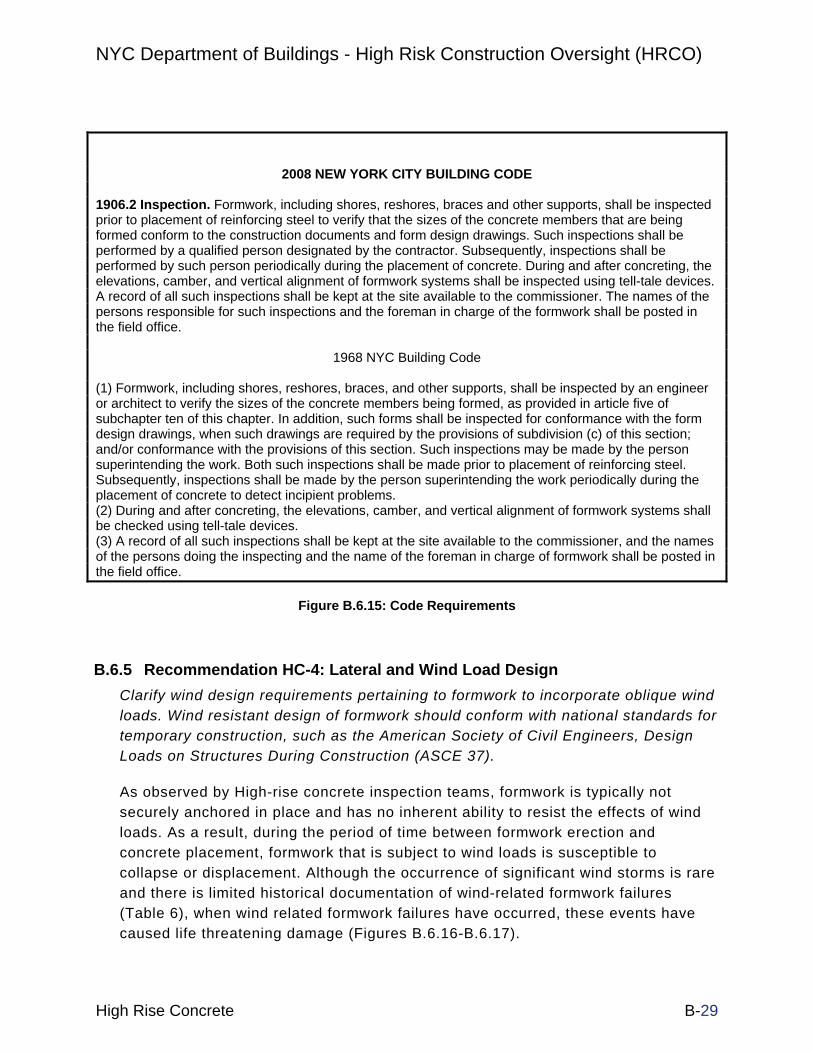
NYC Department of Buildings - High Risk Construction Oversight (HRCO)
High Rise Concrete B-29
2008 NEW YORK CITY BUILDING CODE
1906.2 Inspection. Formwork, including shores, reshores, braces and other supports, shall be inspected prior to placement of reinforcing steel to verify that the sizes of the concrete members that are being formed conform to the construction documents and form design drawings. Such inspections shall be performed by a qualified person designated by the contractor. Subsequently, inspections shall be performed by such person periodically during the placement of concrete. During and after concreting, the elevations, camber, and vertical alignment of formwork systems shall be inspected using tell-tale devices. A record of all such inspections shall be kept at the site available to the commissioner. The names of the persons responsible for such inspections and the foreman in charge of the formwork shall be posted in the field office.
1968 NYC Building Code
(1) Formwork, including shores, reshores, braces, and other supports, shall be inspected by an engineer or architect to verify the sizes of the concrete members being formed, as provided in article five of subchapter ten of this chapter. In addition, such forms shall be inspected for conformance with the form design drawings, when such drawings are required by the provisions of subdivision (c) of this section; and/or conformance with the provisions of this section. Such inspections may be made by the person superintending the work. Both such inspections shall be made prior to placement of reinforcing steel. Subsequently, inspections shall be made by the person superintending the work periodically during the placement of concrete to detect incipient problems. (2) During and after concreting, the elevations, camber, and vertical alignment of formwork systems shall be checked using tell-tale devices. (3) A record of all such inspections shall be kept at the site available to the commissioner, and the names of the persons doing the inspecting and the name of the foreman in charge of formwork shall be posted in the field office.
Figure B.6.15: Code Requirements
B.6.5 Recommendation HC-4: Lateral and Wind Load Design Clarify wind design requirements pertaining to formwork to incorporate oblique wind loads. Wind resistant design of formwork should conform with national standards for temporary construction, such as the American Society of Civil Engineers, Design Loads on Structures During Construction (ASCE 37).
As observed by High-rise concrete inspection teams, formwork is typically not securely anchored in place and has no inherent ability to resist the effects of wind loads. As a result, during the period of time between formwork erection and concrete placement, formwork that is subject to wind loads is susceptible to collapse or displacement. Although the occurrence of significant wind storms is rare and there is limited historical documentation of wind-related formwork failures (Table 6), when wind related formwork failures have occurred, these events have caused life threatening damage (Figures B.6.16-B.6.17).

NYC Department of Buildings - High Risk Construction Oversight (HRCO)
High Rise Concrete B-30
Modified design criteria may also include considerations for exposure conditions as, historically, wind events are prevalent at western water exposures (Figure B.6.18).
The ASCE 37 standard prescribes applicable loads to be considered during the design of temporary structures such as formwork. The standard considers the temporary nature and short load duration when establishing the magnitude of load to be used in design. Lateral loads included in ASCE 37 that apply to formwork design are horizontal construction loads and wind loads. Relative to wind load criteria on temporary structures, ASCE 37 references ASCE 7, Minimum Design Loads for Buildings and Other Structures as the basis.
Figure B.6.16: Formwork Failure at Hudson River Exposure

NYC Department of Buildings - High Risk Construction Oversight (HRCO)
High Rise Concrete B-31
Figure B.6.17: Formwork Failure in Reported 30-40 mph Winds
Table 6: Historic NYC Formwork Wind Events
Address Boro. Incident Date Description
100 Jay Street Brooklyn 7/24/2006 Wind dislodged several formwork deck panels from 27th floor.
246 Spring St. Manhattan 12/23/2007 Wind dislodged shoring element from the 39th Floor
469 West St. Manhattan 3/9/2008 Wind dislodged formwork from the 15th floor
808 Columbus Manhattan 6/11/2008 Wind dislodged formwork in reported winds of 30-40 mph
314 11th Ave Manhattan 10/22/2008 Wind dislodged (2) 3x4 timber posts from 16th floor.
Leading Edge deck lifted, removed voluntarily by contractor

NYC Department of Buildings - High Risk Construction Oversight (HRCO)
High Rise Concrete B-32
Figure B.6.18: Historic Formwork Failures due to Wind Events
Loading criteria for formwork has been reviewed by cross-reference of applicable enforceable codes. The following compares the criteria and differences between the various codes.
Codes reviewed for this study were OSHA 1926.703, OSHA Subpart L, ANSI A10.9-2004, NYC 1968 Building Code and 2008 Building Code, ASCE 7-02 Minimum Design Loads for Buildings and Other Structures, ASCE 37-02 Design Loads on Structures During Construction, and ACI 347-04 Guide to Formwork for Concrete.
The ANSI A10.9-2004 was found to be the most commonly referenced standard. Both the 1968 and 2008 NYC codes reference this ANSI standard. Also, both codes contain design criteria similar to design criteria contained in this ANSI standard. Lateral loading found in ANSI 10.9, Section 7.2.1, is defined as the following.
• The greater of 100 plf along the form edge

NYC Department of Buildings - High Risk Construction Oversight (HRCO)
High Rise Concrete B-33
• 2% of the total dead load on the floor distributed along the slab edge
Wind requirements of ASCE 7 include a minimum criteria of 15 psf and reduced wind speeds reflecting reduced probability of storm events for temporary construction. By comparison the NYC Building Code has similar criteria regarding 100 plf at the form edge and 2% of the dead load. The lateral wind load and uplift is addressed as a specific wind pressure within the NYC code RS9-5. Uplift is addressed within ASCE 7-02, and is included in Chapter 6 as the upward load on the underside of overhangs and canopies. ASCE 7-02 also provides basic wind speed data for coastal areas, prone to hurricane activity, such as New York City. ASCE 37-02 Design Loads on Structures during Construction lists factors that reduce the basic wind speed found in ASCE 7-02 according to an assumed construction period that is less than 5-years. According to ASCE 37, the construction period shall be taken as the time interval from first erection to structural completion of each independent structural system.
Based on an estimated construction period, a factor is given in ASCE 37. That factor reduces the basic wind speed found in ASCE 7 such that the reduced design wind velocity would have the same probability of being exceeded during the construction period as the 50-year mean recurrence interval design wind has during a 50-year period.
B.6.6 Recommendation HC-5: Formwork Construction for Wind Resistance
Require perimeter formwork decking to be positively secured against uplift.
Historically, DOB incident data indicates formwork failures have involved leading edge elements, such as unsecured plywood sheeting that was lifted by the wind along building perimeters. Although some formwork designers provide nailing schedules for decking elements, many designs improperly rely on the self-weight of the assembly alone to resist overturning and liftoff. Requirements for positive connection between decking and rib elements are needed to increase structural integrity of perimeter elements. Although modular engineered formwork systems (Figure B.6.19) require nailed connections between decking and rib elements in the same manner as “stick” assemblies, such systems also provide the added benefit of automatic, positive connection between towers, stringers, and ribs. Usage of such modular systems is commonplace (Table 7).

NYC Department of Buildings - High Risk Construction Oversight (HRCO)
High Rise Concrete B-34
Table 7: Formwork Type Usage
Respondent City Percentage of
Jobs with Modular Engineered Formwork
Average Floor Cycle on Jobs with Modular
Engineered Formwork (days)
Percentage of Jobs with Stick
Forms
Average Floor Cycle on Jobs
with Stick Forms (days)
Chicago, IL 80 3-4 20 3-4 Fairfax County, VA 10 7 90 7
Charlotte, NC 98 NA 2 NA Pompano Beach, FL 25 3 75 5 San Francisco, CA 85 5 15 5
San Jose, CA 85 5 15 7 Toronto, Canada 80 5 20 NA
Figure B.6.19: Modular Engineered Formwork System

NYC Department of Buildings - High Risk Construction Oversight (HRCO)
High Rise Concrete B-35
B.6.7 Recommendation HC-6: Wind Monitoring (Further Study)
Require continual measurement of wind speed and direction during construction at prescribed elevations. Provide an audible early warning system to alert workers to possible wind danger.
Wind velocity and direction are highly sensitive to site-specific characteristics such as terrain, exposure, and surrounding structures. Thus, measurements of wind speed at remote locations9 are not reliable surrogates for all localities when construction safety is in question. Site-specific wind readings will provide Site Safety Managers with the data necessary to mitigate wind-induced hazards. In addition, the Department of Buildings may use this additional site-specific wind data to refine wind-related code requirements.
Wind monitoring technology is established, and has been utilized most notably at 200 Murray Street, a high-rise construction site10 which incorporated ultrasonic anemometers and remote data loggers.
B.6.8 Recommendation HC-7: Wind Tunnel Studies (Further Study)
Conduct wind tunnel studies to observe and characterize wind behavior, and the resulting loads, along the perimeter of a completed concrete forming system. Further, conduct wind tunnel studies to observe and characterize wind behavior, and the resulting loads, throughout the field of a completed concrete forming system.
A review of current literature indicates little guidance exists regarding the behavior and resulting loads that are caused by wind on the leading edges of a concrete forming system at the perimeter of a building. Likewise, little was found as a guide regarding wind loads throughout the field of a completed concrete forming system.
9 NYC wind speeds are commonly measured at LaGuardia Airport, Newark Airport, and Central Park
10 The Goldman Sachs Building, supervised by Tishman

NYC Department of Buildings - High Risk Construction Oversight (HRCO)
High Rise Concrete B-36
B.6.9 Additional HRCO Data
Table 8: Sites with Critical Formwork Defects
Site No.
Boro Notes
3 B311 Concrete specifications limit stripping time to minimum of 48 hours under
best conditions with Type III Cement. Stripping occurring at 24 hours.
4 B112 Formwork design called for 9 floors of reshores, only 2 currently reshored.
4 B1 Incomplete formwork design. Bracing removed day of pour. Reshores
prematurely removed in areas.
5 B1 General contractor stated he used a “rule of thumb” to determine the
amount of reshores needed, number of floors to reshore, and when to remove re-shores.
11 B1 No reshore drawings.
13 B1 No stamped formwork design. Working off set marked “Preliminary, Not for
Construction”
14 B1 Forms stripped prior to knowledge of concrete strength as noted in project
specs.
15 B1 Per Contractor, no form inspections performed. Formwork post spacing not
in conformance. No formwork sequence provided. No knowledge of concrete strength prior to stripping.
15 B1 Incomplete formwork design (missing details for thicker 22” slab).
16 B1 Form bracing not installed per drawings. No form stripping sequence
available.
19 B3 Formwork installation not in conformance with design documents. No
11 Borough of Brooklyn
12 Borough of Manhattan

NYC Department of Buildings - High Risk Construction Oversight (HRCO)
High Rise Concrete B-37
design for cantilevered work platform. No stripping sequence available.
20 B1 Formwork bracing not in conformance with design. Improper shoring posts
(#3 instead of #4).
21 B1 Formwork drawing for 19th floor not available.
23 B3 Formwork stripping sequences not available. No contractor knowledge of
concrete strengths at time of stripping. Reshores removed prior to verification of required strength.
23 B3 Reshoring of balconies not in conformance with drawings.
29 B3 Form bracing not installed in conformance with design.
29 B3 Bracing removed during concrete placement.
29 B3 No reshore sequence design provided.
33 B3 Missing shoring towers. Improper placement of shoring towers.
34 B1 Sequence and timing of formwork cracking not provided in formwork
design.
36 B1 Insufficient number of reshored floors. No formwork stripping sequence
available.
37 B1 No reshoring design provided. Reshores not in conformance with minimum
spacing requirements. Unknown number of required reshored floors.
40 B1 Improper formwork tie-down installation.
41 B1 Formwork design not stamped by PE.
43 B1 Timing of formwork stripping in direct violation of specification.
44 B1 Formwork drawing is for second floor, but was used throughout
construction.
45 B1 Improper formwork installations.
46 B1 Formwork installation not in conformance with design documents.
47 B1 No knowledge of concrete strength prior to stripping. Improper edge post

NYC Department of Buildings - High Risk Construction Oversight (HRCO)
High Rise Concrete B-38
installation.
48 B1 Missing formwork bracing per drawings.
49 B1 Incomplete reshoring design (no reshoring sequence). Missing bracing
detail.
50 B1 Lateral brace removal during pour. No knowledge of concrete strength prior
to stripping.
55 B3 Bracing removed in violation of general notes. Insufficient numbers of
reshored floors.
55 B3
Insufficient numbers of lateral braces installed below forming floor. Most braces not secured to deck. Reshoring and stripping of formwork not per designer’s general notes. Memo issued by designer implies general notes
are “suggestions”.
55 B3 No reshore sequence provided. No formwork design drawings for multi-
level formwork.
56 B1 Lack of reshore spacing specifications. Reshores clustered in areas to
allow localized work in “shore-free” areas.
56 B1 No reshore design provided.
57 B1 Lack of formwork drawings. Using adjacent building’s formwork design. No
vertical formwork specifications. No approved formwork drawings.
57 B1 No reshore sequence provided.
58 B1 No reshore sequence provided.
58 B1 Missing number of shoring towers.
62 B1 Wall forms removed prior to knowledge of concrete strength.
69 B1 No stamped formwork drawings.
72 B1 Improper shore post spacing. No reshore specification.
73 B1 No formwork drawings available.

NYC Department of Buildings - High Risk Construction Oversight (HRCO)
High Rise Concrete B-39
84 B3 No reshore sequence available, based on contractors experience only.
85 B3 Improper tower installation (unstable timber posts)
87 B1 Timber on ends of towers. Formwork workmanship unstable. Missing
reshoring sequence. Lateral shore bracing not in conformance with design.
87 B1 Premature form stripping.
87 B1 Premature lateral bracing removal. No knowledge of concrete strength
prior to stripping.
88 B1 Observed removal of PERI system lateral braces immediately below active casting floor. Design calls for reshoring at 14 days. Unused lateral braces.
88 B1 PERI tower height exceeds design.
90 B1 Premature formwork removal in violation of specifications. No reshore sequence
91 B1 No cracking specification.
91 B1 No stripping sequences available. Sequencing not specified in design.
92 B1 Improper post tie-offs at edge.

NYC Department of Buildings - High Risk Construction Oversight (HRCO)
High Rise Concrete B-40
B.7 SITE SAFETY B.7.1 Description
The High Risk Construction Oversight (HRCO) High-Rise Concrete Team documented numerous instances of unsafe jobsite conditions and developed recommendations to mitigate these hazards. Unprotected edges (fall hazards) were observed to have the greatest potential to endanger the safety of the public as well as that of construction workers themselves (Figures B.7.1-B.7.3). Other aspects of construction such as non-code compliant storage of material throughout the construction site, especially on stripping floors, provide unsafe conditions relative to egress and sources of wind-blown debris. The hazard of falling debris is ever present in New York City. Between January 2006 and June 2008, DOB records list over 200 falling material incidents, most from floors with active stripping operations. Seven significant debris incidents presenting a hazard to the public occurred during the month of March 2009 alone, and were primarily formwork related.
For example, plywood formwork debris fell from the 29th floor in June 2006, striking and injuring a female pedestrian, requiring medical attention. In February 2009, a piece of 3x4 formwork debris fell from the upper floors of a construction site on West 45th Street, Manhattan, injuring a flagman.

NYC Department of Buildings - High Risk Construction Oversight (HRCO)
High Rise Concrete B-41
Figure B.7.1: Debris Accumulation Presenting a Public and Worker safety Hazard. Note
Unprotected and Unsecured Building Edge (Background).

NYC Department of Buildings - High Risk Construction Oversight (HRCO)
High Rise Concrete B-42
Figure B.7.2: Unacceptable Debris Accumulation and Material Storage during Formwork
Operations. Lack of Storage Space Concentrates Material within Work Areas, Impeding Egress Pathways. Note Shoring Post (Center) Stopped Short of Floor over Stacked Material.

NYC Department of Buildings - High Risk Construction Oversight (HRCO)
High Rise Concrete B-43
Figure B.7.3: Stacked and Unsecured Material Presents a Wind Borne Debris Hazard When Placed
Near Building Edges
Additionally, recommendations regarding New York City’s construction inspectors will help establish more consistent DOB inspection procedures and enforcement. As industry complaints regarding inconsistent levels of enforcement are common, recommendations relative to the standardized application of violation thresholds and new low-risk construction practices provide a basis for long term violation reductions.
B.7.2 Recommendation HC-8: DOB Inspector Qualifications
Enhance level of knowledge among DOB inspectors to include qualifications consistent with current NYC Building Code requirements regarding site safety practices, proper concrete formwork installation, and proper shoring and reshoring placement.
Inspectors should be required to receive training equivalent to that of safety professionals in the private sector, such as a Certified Safety Professional, NYC Certified Site Safety Manager, Occupational Health and Safety Technologist, or the

NYC Department of Buildings - High Risk Construction Oversight (HRCO)
High Rise Concrete B-44
Construction Health and Safety Technologist, either through DOB-provided education or through external channels13.
Increasing the inspector’s knowledge base in this manner is critical to maintaining the DOB’s credibility within the construction community, allowing them to enforce code requirements with continued authority and consistency. In addition to basic safety practice education, DOB inspectors should be trained to do the following:
• Read and understand formwork design drawings
• Become ACI Level 1 Certified14
• Understand the importance of proper shoring sequences and practices
• Quickly Identify and Address Risky Construction Operations
B.7.3 Recommendation HC-9: DOB Inspection Procedures
Update and publish standard sets of inspection protocols to create a consistent and uniform level of enforcement.
A repeated industry criticism of DOB inspection practices is the non-uniform level of enforcement. Updated protocols are to include specific inspection check lists listing thresholds for violations, as well as thresholds for Stop Work Orders.
Current DOB inspection checklists and standard operating procedures (SOP), while specific in reference to many code requirements, do not provide guidelines sufficient to provide for a uniform enforcement of safety-critical requirements. For example, inspectors are currently not uniformly equipped to judge the acceptability of common unsafe conditions (Figs. B.7.4-B.7.7). Rather, they rely primarily on their own varying level of training, experience, and degree of tolerance of non-conforming issues.
13 BCSP Board of Certified Safety Professionals, 208 Burwash Avenue, Savoy, IL 61874.
14 The DOB has already begun to certify inspection staff per ACI Level 1

NYC Department of Buildings - High Risk Construction Oversight (HRCO)
High Rise Concrete B-45
Figure B.7.4: Localized Gap Condition at Guardrail. Lack of Specificity Regarding Allowable Gap Distance (if any) Forces Inspector to Make a Potentially Inconsistent Judgment Call
Figure B.7.5: Localized Discontinuous Guardrail Condition at Material Storage Location. Lack of Specificity Regarding Allowable Gap Distances Forces Inspector to Make a Potentially
Inconsistent Judgment Call

NYC Department of Buildings - High Risk Construction Oversight (HRCO)
High Rise Concrete B-46
Figure B.7.6: Building Exposure with Incomplete Edge Protection. Code Provisions Do Not Address Violation Thresholds Relating to Percentage of Exposure without Protection
Figure B.7.7: Localized Variation in Guardrail Height. Code Provisions Do Not Address Allowable Height Tolerances (if any). Lack of Specificity Forces Inspector to Make a Potentially Inconsistent
Judgment Call

NYC Department of Buildings - High Risk Construction Oversight (HRCO)
High Rise Concrete B-47
An upgraded SOP would benefit greatly from an array of easily-recognizable photographic examples. Explicit SOP inspection protocols and thresholds for violations will eliminate the need for DOB inspectors to exercise personal judgment regarding violations. This revised SOP protocol may include the following model requirements, augmenting and clarifying existing protocol guidelines (Figure B.7.8).
• Maintain less than 6” between discontinuous guardrails and building elements, or between collections of stored material and the resumption of guardrail protection. Enforcement level: Violation
• Deflection of guardrail cables shall not exceed ¼” for every foot of unsupported length (tautness)15. Enforcement Level: Violation
• Without Exception, fully compliant guardrails shall be continuously installed throughout building perimeter. Enforcement Level: Stop Work Order
Figure B.7.8: Portion of Current DOB Standard Operation Procedure v6
15 Compare to DOB SOP v6 Section 16 (c), (f)

NYC Department of Buildings - High Risk Construction Oversight (HRCO)
High Rise Concrete B-48
B.7.4 Recommendation HC-10: Housekeeping Requirements
Clarify specific housekeeping requirements in inspection protocols16.
Similar to the need to clarify enforcement of guardrail conditions, and in an attempt to reduce the risk of falling debris, a uniform understanding of acceptable housekeeping conditions is required. An upgraded SOP would benefit greatly from an array of easily-recognizable photographic examples (Figures B.7.9-B.7.11).
Figure B.7.9: Unacceptable Level of Debris Accumulation. Enforcement Level:
Violation
16 Housekeeping provisions to augment OSHA 29 CFR 1926.25

NYC Department of Buildings - High Risk Construction Oversight (HRCO)
High Rise Concrete B-49
Figure B.7.10: Unacceptable Level of Debris Accumulation Presenting a Major Impediment to Egress. Enforcement Level: Stop Work Order
Figure B.7.11: Acceptable Level of Debris Accumulation

NYC Department of Buildings - High Risk Construction Oversight (HRCO)
High Rise Concrete B-50
B.7.5 Recommendation HC-11: Site Safety Hierarchy (Further Study)
Require site safety personnel’s line of accountability to lead to owner (and not to the contractor or CM) to avoid a conflict of interest.
A precedent for this recommendation is Los Angeles where Site Safety managers are hired directly by the owner. Observations and interviews collected during 181 site visits indicate a Site Safety Manager’s ability to maintain appropriate levels of safety on job sites is directly related to the owner’s and contractor’s willingness to support his efforts. A May, 2004 study17 found that the Site Safety Personnel’s authority level is highly correlated with overall safety. Additionally, current American Society of Civil Engineers (ASCE) policy18 states that “Owners should take an active role in project safety.” Enabling safety personnel to pursue their duties unencumbered by conflicts of interest is an efficient way to achieve increased levels of safety.
Site Safety Managers have a purpose, but are currently ineffectual. Even highly-qualified and knowledgeable safety managers were observed to be ineffective, relative to enacting and enforcing safety compliance, without the contractor’s direct support. Because contractors are under significant pressure to adhere to strict construction schedules, they are generally not inclined to delay projects to enforce safety regulations (Figure B.7.12) throughout the construction site. Although cooperation was observed to exist between the General Contractor and Safety Personnel at a number of sites, HRCO team members noted this as the exception rather than the rule.
17 Benchmark Studies on Construction Safety Management in China. Journal of Construction Engineering and Management
18 ASCE Policy Statement #350 (1998)

NYC Department of Buildings - High Risk Construction Oversight (HRCO)
High Rise Concrete B-51
Figure B.7.12: Failure to Tie-off within 10 feet of Unprotected Edge
HRCO field note entry of significance regarding excellent safety coordination:
• 1-Oct. 2008, Site No. 23: Owner-hired Site Safety Manager, observed good safety response over contractor hired Site Safety Manager
• 2-Oct. 2008, Site No. 40: Interview with Site Safety personnel indicate preference is to be hired by owner, and owner involvement improves ability to enforce safety regulations.
• 22-Oct. 2008, Site No. 48: Site safety manager observed that they are more successful on project when they are retained by the owner.
HRCO field note entries of significance regarding poor safety coordination:
• 18-Aug. 2008, Site No. 85: Poor chain of command between Site Safety Manager and trades. Lack of respect between trades and safety manager. Site Safety Manager unable to control project, under pressure to keep low profile.

NYC Department of Buildings - High Risk Construction Oversight (HRCO)
High Rise Concrete B-52
• 27-Aug. 2008, Site No. 90: Limited ability of SSM to maintain control of site. Housekeeping violations and unprotected edge violations previously issued by BEST.
• 24-Sept 2008, Site No. 55: Additional concrete contractor safety personnel onsite, but ineffective.
• 25 Sept. 2008, Site No. 57: Site Safety personnel not effective in maintaining safety. Insufficient perimeter protection. Unprotected edges throughout site. Poor housekeeping
• 21-Oct. 2008, Site No. 56: General contractor slow to address safety issues. Lack of fall protection between buildings. Fall hazards at ladders to stripping floor (Safety violations issued following week following deteriorating conditions).
• 23-Oct. 2008, Site No. 85: Site Safety Manager ineffective. Unprotected edges throughout. Most workers not tied off. No safety coordination or enforcement within project team.
• 5-Nov. 2008, Site No. 85: Site Safety Personnel have no control over site safety. Still inadequate edge protection. No tie off compliance. Blocked egress. Project team is not making safety a priority.
B.7.6 Recommendation HC-12: Upgrading Netting Requirements (Further Study)
Study the effectiveness of enhancing existing netting requirements19.
Current NYC construction industry practice regarding formwork construction relies heavily upon the use of site constructed dimension lumber (stick) assemblies (Figure B.7.13), consisting of timber posts and lumber framing members which typically create large volumes of waste and debris. In recognition of the likelihood that this debris represents a potential hazard, and the further recognition of the potentially serious hazards created if the debris is blown or falls from a building, a number of general contractors have independently elected to utilize full-height vertical netting (Figure B.7.14) to better contain flying debris, in excess of current DOB code requirements.
19 Netting Provisions to augment OSHA 29 CFR 1926.502 and 1926.750

NYC Department of Buildings - High Risk Construction Oversight (HRCO)
High Rise Concrete B-53
As the industry begins to independently move in the direction of more stringent netting requirements, and while public safety remains a high priority, a review of current standards is necessary.
Figure B.7.13: Typical Site Constructed Dimensional Formwork Assembly (Stick Form Construction)

NYC Department of Buildings - High Risk Construction Oversight (HRCO)
High Rise Concrete B-54
Figure B.7.14: Full-height Vertical Netting Provides Additional Barrier to Flying Debris
Further study of cocoon construction practices (Figure B.7.15), which can contain debris more effectively than full-height netting alone, is also warranted. When correctly implemented, cocoon configurations provide protection against worker fall incidents by allowing construction to proceed within an enclosed temporary structure encircling the building footprint. Consideration must be given however, to the cocoon system’s effect on fire safety, wind design and egress.

NYC Department of Buildings - High Risk Construction Oversight (HRCO)
High Rise Concrete B-55
Figure B.7.15: Cocoon Construction in Operation.
B.7.7 Recommendation HC-13: Material Handling (Further Study)
Establish requirements for the use of outrigger systems for material handling.
Outrigger platforms are temporary structures cantilevered off building edges (Figures B.7.16-B.7.17) that can be constructed to provide a continuously-protected material rigging area outside the building footprint. Incorporation of outrigger platforms into the construction scheme will eliminate the need to interrupt otherwise continuous edge protection, allowing rigging and flying operations to proceed in a protected environment20. Additionally, outrigger systems, located and installed at specific locations on each floor, will eliminate subjecting crane booms to lateral loads when material is dragged out of the building interior prior to lifting the load (see also HRCO Crane Rigging Recommendation to restrict the practice of “side pulling” loads).
20 Outrigger systems to comply with OSHA 29 CFR 1926.452(i). Designs to be stamped
and sealed by a registered NY Professional Engineer

NYC Department of Buildings - High Risk Construction Oversight (HRCO)
High Rise Concrete B-56
Figure B.7.16: Acceptable Outrigger System for Material Handling Near Ground Level. Note Uninterrupted Edge Protection.
Figure B.7.17: Acceptable Outrigger System for Material Handling Near Active Floors (Top)

NYC Department of Buildings - High Risk Construction Oversight (HRCO)
High Rise Concrete B-57
The 2008 New York City Building Code §3303.4.5.2 allows material to be stored while overhanging building edges provided they are sufficiently banded and braced. Although instances of code non-compliant material handling and storage practices were rare, concerns were raised regarding the potential of the current practice of material handling and storage to cause a serious incident or accident either through rigging errors, or by creating serious fall hazards (Figure B.7.18).
Also, HRCO site observations confirm that code-compliant placement and rigging of material at building edges occurs coincidentally with code non-compliant removal of edge protection (Figures B.7.19-B.7.20). Thus, edge protection is removed, creating a code non-compliant condition, to allow for the code-compliant practice of placing material at the building edge for lifting to overhead floors.
The HRCO has not identified any typical construction logistics that would preclude the use of outriggers. However, implementation of this recommendation may be benefited by providing a mechanism for contractors to elect not to use out-riggers either by special filing or for certain classes of buildings.
Figure B.7.18: Typical Unacceptable Lack of Edge Protection at Building Edge Coincident with Material Storage. Guardrails Removed over a Large Portion of This Building’s Exposure to
Accommodate Material Piles

NYC Department of Buildings - High Risk Construction Oversight (HRCO)
High Rise Concrete B-58
Figure B.7.19: Current Code-Compliant Material Storage Practice (Piled Material is Banded and Braced) and Accompanying Fall Hazard at Unprotected Edge (Left)

NYC Department of Buildings - High Risk Construction Oversight (HRCO)
High Rise Concrete B-59
Figure B.7.20: Hoisting of Debris Container (Mini) Requires Rigging Operations at Unprotected Edge. Hoisting Will Also Require Crane “Side-Pulling”. Note Lack of Proper Worker Tie-Off
B.7.8 Additional HRCO Data B.7.8.1. Construction Schedule Analysis and Violation Issuance Analysis Two analyses were conducted to evaluate the effectiveness of violation issuances on construction quality and safety issues, and whether there is a statistically significant correlation between the frequency of violations and construction cycle time.
In summary, analysis indicates that issuing a violation has no effect on general code compliance or prevention of violation recurrence. Analysis also concluded that although construction sites with quick construction schedules are likely to contain hazardous housekeeping conditions, these same sites are not any more likely to contain hazardous safety or quality conditions than sites with slow construction schedules.
Construction Schedule Analysis
For the purposes of the HRCO study, violation categories are defined as follows:
• Housekeeping Violations: Instances where significant levels of debris accumulation exist, presenting a hazard to egress or production of falling material.
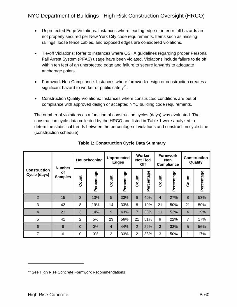
NYC Department of Buildings - High Risk Construction Oversight (HRCO)
High Rise Concrete B-60
• Unprotected Edge Violations: Instances where leading edge or interior fall hazards are not properly secured per New York City code requirements. Items such as missing railings, loose fence cables, and exposed edges are considered violations.
• Tie-off Violations: Refer to instances where OSHA guidelines regarding proper Personal Fall Arrest System (PFAS) usage have been violated. Violations include failure to tie off within ten feet of an unprotected edge and failure to secure lanyards to adequate anchorage points.
• Formwork Non-Compliance: Instances where formwork design or construction creates a significant hazard to worker or public safety21.
• Construction Quality Violations: Instances where constructed conditions are out of compliance with approved design or accepted NYC building code requirements.
The number of violations as a function of construction cycles (days) was evaluated. The construction cycle data collected by the HRCO and listed in Table 1 were analyzed to determine statistical trends between the percentage of violations and construction cycle time (construction schedule).
Table 1: Construction Cycle Data Summary
Housekeeping Unprotected Edges
Worker Not Tied
Off
Formwork Non
Compliance Construction
Quality
Construction Cycle (days)
Number of
Samples
Cou
nt
Perc
enta
ge
Cou
nt
Perc
enta
ge
Cou
nt
Perc
enta
ge
Cou
nt
Perc
enta
ge
Cou
nt
Perc
enta
ge
2 15 2 13% 5 33% 6 40% 4 27% 8 53%
3 42 8 19% 14 33% 8 19% 21 50% 21 50%
4 21 3 14% 9 43% 7 33% 11 52% 4 19%
5 41 2 5% 23 56% 21 51% 9 22% 7 17%
6 9 0 0% 4 44% 2 22% 3 33% 5 56%
7 6 0 0% 2 33% 2 33% 3 50% 1 17%
21 See High Rise Concrete Formwork Recommendations

NYC Department of Buildings - High Risk Construction Oversight (HRCO)
High Rise Concrete B-61
Correlation Analysis was performed to calculate the sample correlation coefficient, r, between the percentage of violations and construction cycle (days) for each violation category. This coefficient varies between -1.0 (perfect negative linear correlation) to 1.0 (perfect positive linear correlation). A correlation coefficient of 0 implies no correlation between the percentage of violations and construction cycle. Correlation coefficients ranged from -0.882 (negative linear correlation for “Housekeeping”) to 0.272 (positive linear correlation for “Unprotected Edges”).
Hypothesis testing was conducted using the sample correlation coefficient to determine if the population correlation coefficient, ρ, was significantly different from 0. With the exception of the “Housekeeping” category, the null hypothesis that there is no linear association between the percentage of violations and construction cycles can not be rejected at the 5% level of significance.
Hypothesis testing was next conducted using the sample correlation coefficient to determine if the population correlation coefficient, ρ, for the “Housekeeping” category was negative. The null hypothesis that there is no linear association between the percentage of “Housekeeping” violations and construction cycles was rejected at the 5% level of significance indicating that there is a strong negative correlation (e.g. the percentage of housekeeping violations decreases with an increase in construction cycle times).
Based on the correlation analysis the null hypothesis of no population correlation between construction cycles and “Housekeeping” violations can be rejected at the 5% level of significance, strongly suggesting the hypothesis of negative linear correlation.
In conclusion, there is no significant evidence of correlation between construction cycles and the percentage of “Unprotected Edges”, “Worker Not Tied Off”, “Formwork Non-Compliance”, and “Construction Quality” violations observed during the HRCO’s summer 2008 site observations
.
Rank Correlation The correlation analysis above was conducted on a relatively few number of data points (construction cycles ranging from 2 through 7 days). Statistical inference that the percentage of “Housekeeping” violations decreases with increased construction cycle days assumes that observations are sampled from a joint normal distribution and that there are no extreme observations.
A rank correlation analysis (less susceptible to the influence of extreme values) was conducted for each construction cycle category to test the null hypothesis that there is no

NYC Department of Buildings - High Risk Construction Oversight (HRCO)
High Rise Concrete B-62
association between the percentage of violations and construction cycles. Data were first ranked in ascending order and the Spearman’s rank correlation coefficient was computed from the rankings.
Hypothesis testing was conducted using Spearman’s rank correlation coefficient to determine if there is a correlation (positive or negative) between the rankings of violation percentages with construction cycles. The null hypothesis that there is no linear association between the ranked percentage of violations and construction cycles can not be rejected at the 5% level of significance. Based on the rank correlation analysis hypothesis testing, there is no statistically significant correlation (5% level of significance) between the ranking of each violation category percentage and construction cycle.
Conclusions Two types of correlation analyses were conducted to evaluate whether there is a statistically significant sample correlation coefficient, r, between the percentage of violations and construction cycle times for each type of violation category.
The correlation analysis assumed that observations are sampled from a joint normal distribution and that there are no extreme observations. The null hypothesis of no population correlation between construction cycles and “Housekeeping” violations can be rejected at the 5% level of significance and suggests strong evidence supporting the hypothesis of negative linear correlation (decrease in the percentage of “Housekeeping” violations with an increase in construction cycle times). There is no significant evidence of correlation between construction cycles and the percentage of Unprotected Edges, Worker Not Tied Off, Formwork Non-Compliance, and Construction Quality violations.
B.7.8.2. Effect of Heightened Enforcement
In addition to the HRCO’s standard safety observation protocol (for which jobsites were selected by a standard procedure discussed in the high-rise concrete methodology section of this report), a select group of sites was chosen to receive additional scrutiny to assess the effect of repeated enforcement. Violation timeline data were analyzed to evaluate effects of heightened enforcement and violation issuances for the following sites:
• Site No. 85, Brooklyn
• Site No. 84, Manhattan
• Site No. 56, Manhattan

NYC Department of Buildings - High Risk Construction Oversight (HRCO)
High Rise Concrete B-63
• Site No. 57, Manhattan
Violation category data culled from HRCO site visits (Figures B.7.21-B.7.24) were rated as “Satisfactory”, “Unsatisfactory, No Violation Issued”, “Unsatisfactory, Violation Issued” and, “Stop Work Order in Effect” in Table 2.
A greater percentage of the visits with “Unsatisfactory” ratings (with or without violations issued) or stop work orders is reported for the “Formwork Compliance” (85%) and “Construction Quality” (86%) categories.
Table 2 - Visit Summary
Number of Visits
Satisfactory Visit
Unsatisfactory, No Violation
Issued
Unsatisfactory, Violation Issued
Stop Work Order In Effect
Percent "Unsatisfactory" or
Stop Work Order Unprotected
Edges 17 20 12 0 65
Worker Tie Off 19 25 1 0 58 Housekeeping 21 12 13 0 54
Formwork Compliance 3 8 6 3 85
Construction Quality 2 8 2 2 86
Overall 62 73 34 5 64
Effect of Violations
Timeline data were evaluated to determine the effect of violations. As summarized in Table 3, the number of visits to achieve a “Satisfactory” rating averaged 2.7 visits when no violations were issued and 3.0 when violations were issued. On average, issuing violations did not decrease the number of visits to achieve a “Satisfactory” rating.
A contingency table analysis was conducted to evaluate whether there was an association or dependence between the number of repeat visits to achieve a “Satisfactory” rating and violation issuance. The “Unsatisfactory” data with or without violations were first classified as “acceptable” if a “Satisfactory” rating was achieved in one to two repeat visits or “unacceptable” if achieved in three or more visits. Data were also cross-classified by whether violations were issued or not. The cross-classified data are summarized in Table 4.

NYC Department of Buildings - High Risk Construction Oversight (HRCO)
High Rise Concrete B-64
Table 3 – Number of Repeat Visits
Satisfactory Unsatisfactory
Visit, No Violation Issued
Unsatisfactory, Violation Issued
Stop Work Order in Effect
Count 9 20 12 Min. 1 1 1 Max. 2 9 8
Unprotected Edges
Average 1.3 3.4 3.5 Count 16 22 1 Min. 1 1 5 Max. 4 6 5
Worker Tie Off
Average 1.6 2.4 5 Count 8 12 13 Min. 1 1 1 Max. 3 5 5
Housekeeping
Average 1.5 2.3 2.7 Count 2 2 2 2 Min. 1 1 1 1 Max. 1 3 2 2
Formwork Compliance
Average 1 2 1.5 1.5 Count 1 1 Min. 1 1 Max. 1 1
Construction Quality
Average 1 1 Count 36 57 28 2 Min. 1 1 1 1 Max. 4 9 8 2
Overall
Average 1.5 2.7 3.0 1.5
Table 4 – Violations Issued Contingency Table
Number of Visits to "Satisfactory" 1 to 2 3 or More Actual Expected Actual Expected Total No Violation 34 30.8 23 26.2 57
Violation 12 15.2 16 12.8 28 Total 46 39 85

NYC Department of Buildings - High Risk Construction Oversight (HRCO)
High Rise Concrete B-65
Hypothesis testing was conducted to determine if there are statistical differences between the actual and expected number of visits in the four categories of Table 4. The null hypothesis that there is no linear association between the actual and expected number of visits to achieve a “Satisfactory” rating was rejected at both the 5% and 10% level of significance, indicating that there is no statistical evidence that violations are associated with the number of visits. Issuing a violation has no effect on reducing the number of visits to achieve a “Satisfactory” rating.
Moving Forward
This study is limited to four sites over a limited time period. Consequently, additional investigation may be warranted to gage the effect of increased enforcement (especially stop work order efficacy). Further investigation may be performed as outlined in the following procedure.
1. Select five sites with a history of safety violations for additional scrutiny within five subject categories: Unprotected edges, Worker Tie-off, Housekeeping, Formwork Compliance and Construction Quality.
2. Confirm violation thresholds for the five subject categories, for example, establish pictorial reference standards for acceptable levels of housekeeping debris.
3. Visit each site as noted below and issue violations and stop work orders when warranted, but with a zero-tolerance policy towards infractions. For example, stop work orders for debris accumulation must still be issued even if workers were “in the process of addressing the issue”.
Table 5: Reinspection Frequencies
Floor Cycle (Days)
Minimum Visit Frequency
2 Every Two Work Days
3 Every Three Work
Days
4 Every Four Work
Days
5 or More Every Work Week

NYC Department of Buildings - High Risk Construction Oversight (HRCO)
High Rise Concrete B-66
4. Assess performance over a two-month period.
5. Sites with improved levels of compliance may be audited monthly to ascertain levels of continued compliance.
6. Continued, repeat non-compliance indicates insufficient deterrent levels, warranting the DOB’s reevaluation of penalties. Increased violation fees and mandatory stop work orders may be effective in increasing compliance levels.

NYC Department of Buildings - High Risk Construction Oversight (HRCO)
High Rise Concrete B-67
Figure B.7.21: HRCO Condition Report Timeline at Site No. 85, Brooklyn. Note Appearance of New Controlled Inspector and Lather Crew on 18-Sep.

NYC Department of Buildings - High Risk Construction Oversight (HRCO)
High Rise Concrete B-68
Figure B.7.22: HRCO Condition Report Timeline at Site No. 84, Manhattan

NYC Department of Buildings - High Risk Construction Oversight (HRCO)
High Rise Concrete B-69
Figure B.7.23: HRCO Condition Report Timeline at Site No. 56, Manhattan

NYC Department of Buildings - High Risk Construction Oversight (HRCO)
High Rise Concrete B-70
Figure B.7.24: HRCO Condition Report Timeline at Site No. 57, Manhattan

NYC Department of Buildings - High Risk Construction Oversight (HRCO)
High Rise Concrete B-71
B.8 WORKER FALLS B.8.1 Description
The High Risk Construction Oversight (HRCO) High-Rise Concrete Team observed significant numbers of safety hazards involving missing or misuse of required fall hazard protection, including tie-off safety practices (Table 1).
Existing fall-prevention requirements (edge protection, tie-offs, etc.) are currently included in the NYC Building Code and Federal OSHA CFR 1926.500 regulations. Code provisions are sufficient to mitigate these hazards; however, the provisions are routinely ignored and/or violated.
HRCO High-Rise Concrete Team observations indicate, in general, a worker’s lack of basic tie-off knowledge. This lack of knowledge is typically coupled with a reluctant attitude, on the part of the worker, to comply with personal safety regulations and a relaxed approach, on the part of the contractor, to enforce proper fall protection regulations at the site. This lax attitude, on the part of the individual worker, is exacerbated at construction sites where the Site Safety Personnel’s line of accountability inhibits proper enforcement of safety regulations, or where the project team does not provide the support required to execute proper safety protocols.
Table 1: HRCO Observed Fall Violations
All Active Projects
Number of Site Observations 181
Unprotected Edges 78 (43%)
Tie-off Non-compliance 57 (31%)
Preventing fall hazard conditions, such as those during formwork operations (Figure B.8.1) can be accomplished with minimal cost when the contractor consciously anticipates safety solutions. In the case of typical site constructed dimension lumber22 (stick) form assemblies, proper lanyard anchor points can be built into the formwork substructure and access ports for lanyards can be integrated into decking systems. The use of retractable lanyards (Figure B.8.2) can then provide adequate worker mobility throughout the entire deck area until proper guardrails are fully installed.
22 Typically consisting of timber posts and lumber framing members
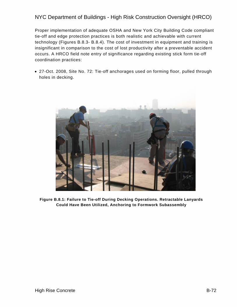
NYC Department of Buildings - High Risk Construction Oversight (HRCO)
High Rise Concrete B-72
Proper implementation of adequate OSHA and New York City Building Code compliant tie-off and edge protection practices is both realistic and achievable with current technology (Figures B.8.3- B.8.4). The cost of investment in equipment and training is insignificant in comparison to the cost of lost productivity after a preventable accident occurs. A HRCO field note entry of significance regarding existing stick form tie-off coordination practices:
• 27-Oct. 2008, Site No. 72: Tie-off anchorages used on forming floor, pulled through holes in decking.
Figure B.8.1: Failure to Tie-off During Decking Operations. Retractable Lanyards Could Have Been Utilized, Anchoring to Formwork Subassembly

NYC Department of Buildings - High Risk Construction Oversight (HRCO)
High Rise Concrete B-73
Figure B.8.2: Retractable Lanyard
Figure B.8.3: Proper Tie-off. Note Use of Built-in Anchor Points on Engineered Formwork (Prefabricated Steel) Towers

NYC Department of Buildings - High Risk Construction Oversight (HRCO)
High Rise Concrete B-74
Figure B.8.4: Tie-off to Formwork Substructure Using Retractable Lanyard
B.8.2 Recommendation HC-14: Fall Hazard Awareness
Implementation of a fall hazard awareness campaign through the use of posters, ads, and training at each jobsite for workers before they are allowed on site.
Worker falls at construction sites account for more fatalities than any other cause23 (Table 2), thus any change in fall rates will have a significant impact upon fatality reduction. Continued implementation of the DOB’s current fall hazard awareness campaign will be relied upon to positively effect changes to worker attitudes towards fall prevention. Similar OSHA awareness programs were able to cut fatal trenching incidents by half over a four year period.
23 Nationwide, the Bureau of Labor Statistics attributes 442 of 1,178 (38%) construction fatalities to falls

NYC Department of Buildings - High Risk Construction Oversight (HRCO)
High Rise Concrete B-75
Table 2: Historical DOB Accident-Incident Data. 2-January 2006 to 30-June 2008
Incident Accident Injuries Fatalities
All Causes, All Categories (Concrete)
1133
(132)
321
(58)
389
(63)
49
(6)
Worker Fell, All Categories (Concrete)
182
(31)
166
(28)
151
(26)
27
(4)
Worker Fell as % of All Causes
(Concrete)
16.1%
(23.5%)
51.7%
(48.3%)
38.8%
(41.3%)
55.1%
(66.7%)
Figure B.8.5: Current NYC DOB Fall Awareness Poster

NYC Department of Buildings - High Risk Construction Oversight (HRCO)
High Rise Concrete B-76
B.8.3 Recommendation HC-15: Contractor Documentation (Further Study)
Require contractor to document remedial actions taken when workers are identified as non-compliant regarding safety measures, including tie-off requirements. Remedial actions could include additional training sessions, suspension, or removal from job site.
Contractors and onsite safety team members are best equipped to identify and rectify fall hazard issues (Figure B.8.6). Furthermore, these individuals have the most at stake when an accident occurs. Therefore, conscious recognition and acknowledgement of remedial actions on the part of the contractor are warranted.
Figure B.8.6: Commonly Observed Failure to Tie-off During Formwork Erection Operations
B.8.4 Recommendation HC-16: Repeat Offense Enforcement (Further Study)
Require a “two strikes and you’re out” provision to be levied against the contractor in the event the contractor fails to enforce safety regulations and procedures. This clause would require that the project is shut down a prescribed number of days after a predetermined number of code violations or reportable incidents. The purpose of the shut down is to provide the contractor a period of time to properly implement safety measures.

NYC Department of Buildings - High Risk Construction Oversight (HRCO)
High Rise Concrete B-77
The threat of DOB-issued violations for code violations, such as poor housekeeping and improper tie-off procedures presenting a hazard to the public was found to be insufficient to ensure conformance to safety requirements. Also, repeat offenses are common (Figures B.8.7- B.8.9).
Figure B.8.7: Initial Failure to Tie-off at Site No. 86, 3-Sept. 2008 (OSHA Violation)

NYC Department of Buildings - High Risk Construction Oversight (HRCO)
High Rise Concrete B-78
Figure B.8.8: Repeat Failure to Tie-off at Site No. 86, 10-Sept. 2008 (OSHA Violation)
Figure B.8.9: Repeat Failure to Tie-off at Site No. 86, 24-Nov. 2008 (OSHA Violation)
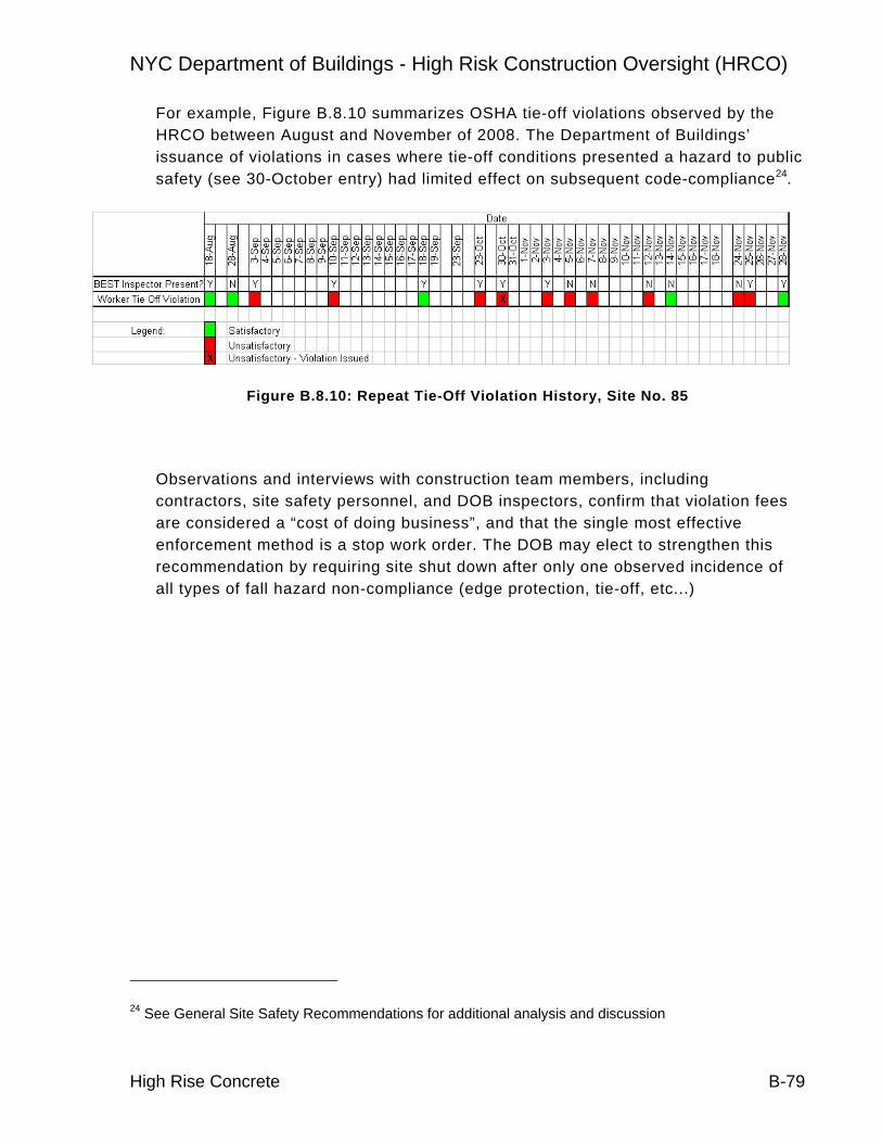
NYC Department of Buildings - High Risk Construction Oversight (HRCO)
High Rise Concrete B-79
For example, Figure B.8.10 summarizes OSHA tie-off violations observed by the HRCO between August and November of 2008. The Department of Buildings’ issuance of violations in cases where tie-off conditions presented a hazard to public safety (see 30-October entry) had limited effect on subsequent code-compliance24.
Figure B.8.10: Repeat Tie-Off Violation History, Site No. 85
Observations and interviews with construction team members, including contractors, site safety personnel, and DOB inspectors, confirm that violation fees are considered a “cost of doing business”, and that the single most effective enforcement method is a stop work order. The DOB may elect to strengthen this recommendation by requiring site shut down after only one observed incidence of all types of fall hazard non-compliance (edge protection, tie-off, etc...)
24 See General Site Safety Recommendations for additional analysis and discussion

NYC Department of Buildings - High Risk Construction Oversight (HRCO)
High Rise Concrete B-80
B.9 SPECIAL INSPECTION AND CONSTRUCTION QUALITY B.9.1 Description
The High Risk Construction Oversight (HRCO) High-Rise Concrete Team documented numerous instances of the fabrication and installation of reinforcing steel that did not comply with code requirements or industry standards. Furthermore, the HRCO High-Rise Concrete Team has observed numerous instances of inadequate and/or inconsistent inspection of installed reinforcing steel.
Of the 98 active site observations completed by HRCO engineers, forty-nine percent (49%) contained construction defects. Construction defects include New York City Building Code violations, violations of the Building Code Requirements for Structural Concrete, (ACI 318), and work that did not comply with the structural design drawings and/or the approved shop drawings. Deficient conditions broadly include the following:
• Improper bar placement
• Improper bar fabrication
• Ineffective special inspection
Although the HRCO site observation program noted many instances of low quality bar fabrication and placement, proper procedures were observed in New York City at both Union and Non-Union worksites. Knowledge resources such as the Lathers Union’s Queens training facility actively promote industry best practices and code-compliant installations.

NYC Department of Buildings - High Risk Construction Oversight (HRCO)
High Rise Concrete B-81
B.9.2 Recommendation HC-17: Special Inspection Rule
Strengthen outreach to industry on Special Inspection qualifications, and enforce the requirement that all Special Inspectors are properly registered and/or certified in compliance with NYC Special Inspection Rule requirements, effective July 1, 2009.
Based on HRCO observations, the percentage of structures found to contain critical construction defects (Tables 1-2, Figs. B.9.1-5), despite direct oversight in each case by a controlled inspector25, supports the actions previously taken by the DOB to improve special inspector expertise. In light of actions taken by the DOB, concerns have been raised by construction industry leaders regarding the industry’s ability to provide adequate numbers of properly-qualified inspectors prior to the July 2009 deadline. Therefore the DOB’s industry outreach will be critical in ensuring a smooth transition to the new inspector requirements.
Table 1: HRCO Construction Quality Defect Rate
Number of Active, Engineer-Inspected Site Observations
90
Number of Observed Quality Issues 46 of 90 (51%)
Number of Observed Quality Issues Deemed Critical
23 of 46 (50%)
25 Now “Special Inspector” under The 2008 NYC Building Code

NYC Department of Buildings - High Risk Construction Oversight (HRCO)
High Rise Concrete B-82
Table 2: Typical Critical Construction Defects
Improper placement of shear reinforcement
Insufficient numbers of installed shear reinforcement elements
Improper column hoop steel installation
Improper bar engagement
Severe bar congestion
Improper column splice configurations
Poor fabrication practices
Poor bar Fit-up
Figure B.9.1: Typical Critical Quality Defect: Column Splices Noncompliant with ACI. Conditions Subsequently Remedied to the Satisfaction of the Engineer of Record

NYC Department of Buildings - High Risk Construction Oversight (HRCO)
High Rise Concrete B-83
Figure B.9.2: Typical ACI-Compliant Splice Detail

NYC Department of Buildings - High Risk Construction Oversight (HRCO)
High Rise Concrete B-84
Figure B.9.3: Typical Critical Quality Defect: Improper Shear Stirrup Engagement. Conditions Subsequently Remedied to the Satisfaction of the Engineer of Record
Figure B.9.4: Typical Critical Quality Defect: Bar Congestion and Improper Shear Stirrup Engagement. Conditions Subsequently Remedied to the Satisfaction of the
Engineer of Record

NYC Department of Buildings - High Risk Construction Oversight (HRCO)
High Rise Concrete B-85
Figure B.9.5: Typical ACI-Compliant Stirrup Engagement Configurations
B.9.3 Recommendation HC-18: Field Inspection
Enhance level of knowledge among DOB inspectors to include qualifications consistent with the current NYC Building Code (Table 3), specific to ACI Special Inspector training, to promote consistent enforcement of concrete practices, including field testing procedures.
Currently, DOB inspectors generally lack sufficient training to consistently enforce critical quality issues. This is because there is no standard training procedure in place that addresses these types of issues. To appropriately enforce critical DOB construction quality code requirements, inspectors must possess a sufficient level of knowledge of the material at hand, and meet or exceed the special inspector’s level of expertise in the field.
The Department of Buildings has already taken steps to certify BEST inspectors as ACI Level-1 Technicians. This education will allow inspectors to better assess the performance of field personnel responsible for sampling and approval of freshly-delivered concrete. Furthermore, ACI Level-1 training is a prerequisite to enroll in the Concrete Construction Special Inspector Program. This program covers topics

NYC Department of Buildings - High Risk Construction Oversight (HRCO)
High Rise Concrete B-86
critical to proper steel placement, such as tolerances, and topics critical to proper concrete consolidation.
Table 3: DOB Inspector Qualifications to Match Requirements for Special Inspectors, NYC BC 1627
B.9.4 Recommendation HC-19: Inspection of Testing Labs
Enhance level of knowledge among DOB personnel to include qualifications consistent with the current NYC Building Code (Table 3), specific to ACI Special Inspector training, and other similar certifications to promote consistent inspection of laboratory practices and conditions.
Training of DOB personnel consistent with this recommendation is critical regarding the DOB’s continued, periodic auditing of concrete testing laboratories for quality and code compliance. HRCO inspections have shown that laboratory quality is highly variable, with each laboratory displaying at least some level of non-conformance with code-required testing procedures (see section B.3.2). Additionally, as the DOB will require testing laboratories to obtain AASHTO26 accreditation by July of 2010, it will be necessary for the DOB knowledge base to
26 American Association of State Highway and Transportation Officials

NYC Department of Buildings - High Risk Construction Oversight (HRCO)
High Rise Concrete B-87
remain current with AASHTO requirements through education and training programs.
B.9.5 Recommendation HC-20: Reinforcing Bend Quality Assurance
Require documentation through photo and/or video that site bending practice complies with accepted industry standards and tolerances. Conformance may be spot checked by the DOB through inspection of logs and field conditions.
HRCO engineers observed numerous instances of fabricated reinforcing that did not conform to industry standards27 as dictated by The New York City Building Code (Figures B.9.6- B.9.7). A failure of the construction industry to provide quality bar fabrication resulted in this recommendation since improper bar fabrication is likely to introduce critical structural defects.
Augmentation of the special inspector’s existing daily reporting documents to include photo documentation of proper and consistent bend quality would allow the Department of Buildings to verify that best bending practices in conformance with code requirements are being utilized regularly. Without this type of documentation (and without constant observation by a DOB inspector), the DOB will be unable to confirm that improved procedures are being enacted.
27 Specifically American Concrete Institute (ACI) Requirements
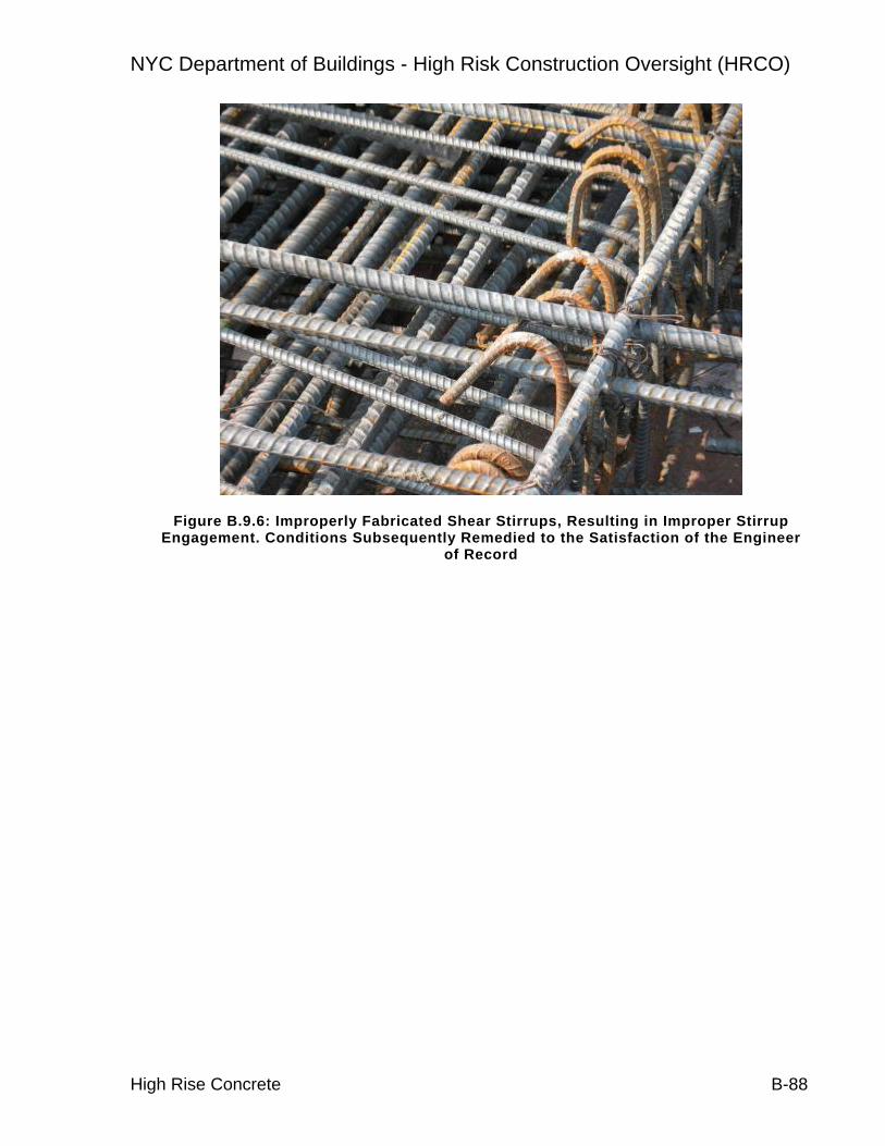
NYC Department of Buildings - High Risk Construction Oversight (HRCO)
High Rise Concrete B-88
Figure B.9.6: Improperly Fabricated Shear Stirrups, Resulting in Improper Stirrup Engagement. Conditions Subsequently Remedied to the Satisfaction of the Engineer
of Record

NYC Department of Buildings - High Risk Construction Oversight (HRCO)
High Rise Concrete B-89
Figure B.9.7: Bar Fabrication Noncompliant with ACI28. Conditions Brought to the Attention of the Engineer of Record
B.9.6 Recommendation HC-21: Reinforcing Placement Quality Assurance
Require documentation through photo and/or video that steel placement complies with accepted industry standards and tolerances. Conformance may be periodically spot checked by the DOB through inspection of construction logs and field conditions.
HRCO engineers observed numerous instances of installed reinforcing that did not conform to the design documents, the approved shop drawings, or industry-standard code requirements (Figures B.9.8- B.9.10). A failure of the construction industry to monitor, install, and provide quality bar placement resulted in this recommendation since improper bar placement and installation will likely introduce structural defects, some of which may be critical.
28 Bend Radius is Tighter than Allowed by American Concrete Institute (ACI) Specifications

NYC Department of Buildings - High Risk Construction Oversight (HRCO)
High Rise Concrete B-90
The justification to augment the special inspector’s existing daily reporting documents to include photo and/or video documentation of bar placement is twofold. One, the Department of Buildings will be able to verify upon review of the documentation that bar placement is in conformance with code requirements (without the need for constant on-site observation by a DOB inspector); and, two, the documentation will allow review of constructed assemblies by design professionals if placement questions arise.
Figure B.9.8: Lack of Proper Shear Stirrup Engagement. Condition Soon to be Hidden by Concrete Encasement. Conditions Brought to the Attention of the
Engineer of Record

NYC Department of Buildings - High Risk Construction Oversight (HRCO)
High Rise Concrete B-91
Figure B.9.9: Column Bar Congestion. Conditions Brought to the Attention of the Engineer of Record

NYC Department of Buildings - High Risk Construction Oversight (HRCO)
High Rise Concrete B-92
Figure B.9.10: Severe Bar Congestion29. Conditions Brought to the Attention of the Engineer of Record
29 American Concrete Institute Specifications Require Minimum Spacing Between Bars, Greater of One Inch or Diameter of Bar to Allow for Proper Concrete Consolidation

NYC Department of Buildings - High Risk Construction Oversight (HRCO)
High Rise Concrete B-93
B.9.7 Additional HRCO Data
Table 4: Sites with Critical Quality Defects
Address Boro Notes
3 B330 Insufficient stirrup Engagement.
4 B131 Insufficient stirrup engagement
14 B1 Insufficient stirrup engagement. Bar Congestion
14 B1 Improper hook fabrication
15 B1 Insufficient stirrup engagement. Improper column tie fabrication and
installation
45 B1 Improper Splice Configurations, Improper Bending of Embedded Steel
48 B1 Improper Splice Configurations, Improper Bending of Embedded Steel. Bar
Congestion
55 B3 Insufficient Column tie engagement. Improper hook fabrication. Improperly
placed column bars
67 B1 Improper Splice Configurations, Improper Bending of Embedded Steel
72 B1 Improper Splice Configurations, Improper Bending of Embedded Steel
72 B1 Improper stirrup Engagement
74 B1 Bar Congestion. Insufficient stirrup engagement. Improper column bar
placement. Improper splice configurations
84 B1 Improper Splice Configurations. Insufficient stirrup engagement
84 B1 Improper Splice Configurations, Improper Bending of Embedded Steel
30 Borough of Brooklyn
31 Borough of Manhattan

NYC Department of Buildings - High Risk Construction Oversight (HRCO)
High Rise Concrete B-94
84 B1 Improper Splice Configurations, Improper Bending of Embedded Steel
85 B3 Improper Stirrup Engagement. Improper hook fabrication. Improper column
and wall tie engagement
40 B1 Improper placement of shearwall reinforcement, insufficient bar encapsulation
47 B1 Insufficient numbers of shear stirrups installed at transfer beams. Misinstalled shear reinforcement
58 B1 Improper placement of column tie and shear reinforcement
83 B1 Improper stirrup configurations at grade beam

NYC Department of Buildings - High Risk Construction Oversight (HRCO)
High Rise Concrete B-95
B.9.8 Impact of Construction Quality Deficiencies
Proper construction and inspection procedures will significantly improve construction quality related to load carrying capacity of structural members. Defects in construction quality may remain unrealized for years or decades as the applied load is generally less than the design load. However, it is likely that a critical loading event could occur during the life of the structure resulting in distress or collapse (e.g. wind loads from a major hurricane). An example to justify the need for proper inspection oversight is illustrated below.
• On 25-September, 2008, HRCO staff observed three, second floor transfer girders with ACI-noncompliant shear steel engagement32 (Figure B.9.11). As constructed, only two of the six shear stirrup legs at the beam soffit were properly hooked around longitudinal reinforcement. Preliminary calculations indicate this bar configuration would have resulted in a 33% reduction in beam shear capacity. This reduced shear capacity could have resulted in serviceability and/or durability issues or, possibly structural failure. A DOB stop work order was put in place until the beams were certified complete and corrected to the satisfaction of the engineer of record.
• Although an initial review of shop and design drawings confirmed sufficient numbers of bottom longitudinal bars, the contractor missed drawing notes requiring the anchorage of all shear hooks with additional steel. A properly trained special inspector would likely have identified not only the noted additional steel requirements, but easily brought the readily-observable code noncompliant conditions to the attention of the contractor and engineer.
32 ACI-318 §12.13.2.1

NYC Department of Buildings - High Risk Construction Oversight (HRCO)
High Rise Concrete B-96
Figure B.9.11: Second Floor Transfer Girder with Improperly Developed Shear Reinforcing. Site No. 47
• The same site was visited on 10-October, 2009 and the girder configurations were compared to the stamped design drawing. At this time HRCO staff noted two second floor transfer girders with insufficient numbers of installed shear stirrup sets (Figure B.9.12), bar congestion (Figure B.9.13), and insufficient numbers of installed longitudinal beam top bars. Of the specified 67 sets of shear reinforcement, only 47 sets were installed. Similar to the prior incident, a stop work order was put in place by the DOB until corrective actions could be taken to the satisfaction of the Engineer of Record. Preliminary calculations indicate that shear capacity resulting from this configuration was reduced by 20%. Furthermore, the combined effects of both the September and October defects would have resulted in a shear capacity loss of 44% had these conditions not been remediated.
• Again, it is likely a properly trained special inspector would have identified the egregious lack of sufficient numbers of reinforcing bars, and brought this condition to the attention of the contractor and engineer.
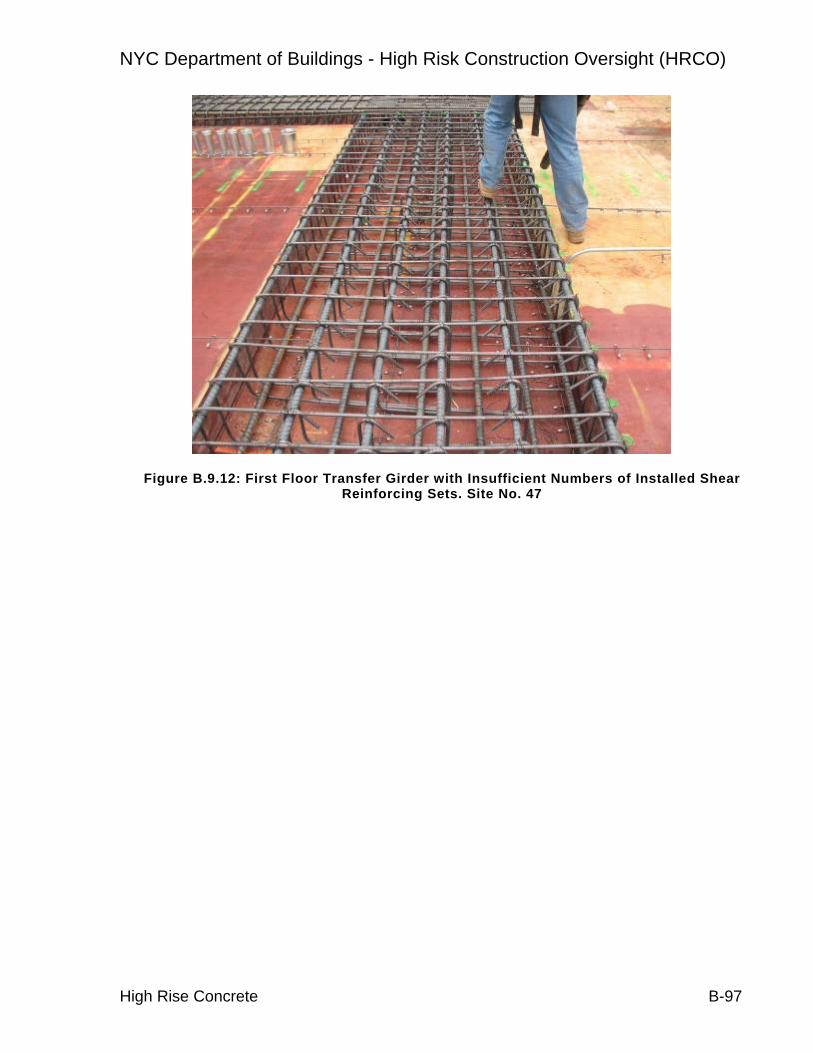
NYC Department of Buildings - High Risk Construction Oversight (HRCO)
High Rise Concrete B-97
Figure B.9.12: First Floor Transfer Girder with Insufficient Numbers of Installed Shear Reinforcing Sets. Site No. 47

NYC Department of Buildings - High Risk Construction Oversight (HRCO)
High Rise Concrete B-98
Figure B.9.13: First Floor Transfer Girder Bar Congestion. Site No. 47

NYC Department of Buildings - High Risk Construction Oversight (HRCO)
High Rise Concrete B-99
B.10 PLAN REVIEW B.10.1 Description
The High Risk Construction Oversight (HRCO) High-Rise Concrete Team reviewed a number of construction document sets containing structural engineering drawings that had been submitted to the DOB as part of the permitting process. Furthermore, HRCO team members performed a review of the existing NYC Building Code provisions pertaining to construction document and peer review requirements.
Review of construction documents identified structural design drawings containing incomplete information according to generally accepted industry standards such as American Concrete Institute (ACI) document entitled Building Code Requirements for Structural Concrete, ACI 318, ACI document entitled Details and Detailing of Concrete Reinforcement, ACI 315 and the Manual of Standard Practice published by the Concrete Reinforcing Steel Institute. Incomplete drawing information severely hampers both the construction and peer review processes, is potentially indicative of a substandard level of quality of the structural design work, and could potentially lead to structural integrity and life safety issues in the constructed building.
To the extent that many jurisdictions outside New York City practice high levels of structural design review, the precedent for increased levels of oversight has been established. Responses to the HRCO’s benchmark survey (Table 1) suggest New York City’s adoption of more stringent plan review criteria would be in line with other building departments nationwide.

NYC Department of Buildings - High Risk Construction Oversight (HRCO)
High Rise Concrete B-100
Table 1: Plan Review Practices
Respondent
Percentage of Major Projects Subjected to
Detailed Structural Review
Percentage of Major Projects
Subjected to Partial Structural Review
Boston - 100 Chicago 99 -
Fairfax County - 100 Honolulu - 100
Los Angeles 100 - Philadelphia 100 - San Diego 100 -
San Francisco 100 - San Jose 100 - Seattle - 100 Toronto -33 90
B.10.2 Recommendation HC-22: Monitoring of Peer Review
Retain professional engineers on behalf of DOB to monitor that peer reviews of identified projects are properly conducted as required by the NYC Building Code.
Peer review, by an independent structural engineer, is an essential component of the design and construction process and is standard practice in many jurisdictions. A majority of major buildings34 may qualify for peer review under the current criteria35 contained in the NYC Building Code. This criteria includes, in part:
1. Buildings in Occupancy Category IV or more than 50,000 SF of framed area.
2. Buildings with aspect ratios of seven or greater
3. Buildings greater than 600 feet in height or more than 1,000,000 SF gross floor area
33 Remaining 10% Self Certified by Design Professional
34 2008 NYC Building Code BC 3310
35 2008 NYC Building Code BC 1627

NYC Department of Buildings - High Risk Construction Oversight (HRCO)
High Rise Concrete B-101
4. Buildings taller than seven stories where any element supports in aggregate more than 15% of the building area
5. Buildings designed with non-linear analysis
6. As requested by the Commissioner
The identification of structures qualifying for peer review under requirements of BC 1627 requires a structural engineering background, and the number of structures that qualify for peer review may be significant. Therefore, at least one full-time, qualified structural engineer working either on staff or on behalf of the DOB will be required to oversee peer review work. This oversight should include the following:
• Positive identification of structures meeting thresholds for peer review.
• Monitoring of peer review submission procedures.
• Periodic auditing of completed peer reviews for quality and completeness
In addition, the DOB may elect to develop programs for identification of critical structural members not currently addressed in BC 1627 for review, and screening of projects submitted for plan examination approval to prioritize for structural plan review.
B.10.3 Recommendation HC-23: Structural Drawing Information
Require minimum level of information to be included on structural building drawings, including member end reactions and details with sufficient information to properly convey the design intent.
Current DOB plan review procedures do not include technical review sufficient to identify adequacy as prescribed by the NYC Building Code. Furthermore not all sets of structural drawings contain sufficient levels of design information.36 In addition to existing requirements, and in order to facilitate the peer-review process, the following additional information should be required.
• Member end reactions, including flexure, shear, and axial reactions will be noted on the structural drawings for major structural members such as transfer girders, beam girders, and shear walls.
• Details, and detailing, consistent with ACI 315, Part A
36 2008 NYC Building Code BC 1603 and BC 106.7

NYC Department of Buildings - High Risk Construction Oversight (HRCO)
High Rise Concrete B-102
• Sufficient notes and details to properly convey the design intent.
B.10.4 Recommendation HC-24: Monitoring of Structural Information Quality
DOB should retain professional structural engineers to review drawings to verify that the minimum level of structural information is contained on each set of structural drawings, shop drawings, and formwork drawings. Information to include requirements contained in ACI publications as noted in current NYC Building Code.
The volume of plan submissions is significant; therefore, a monitoring program supervised by at least one qualified, full-time structural engineer with sufficient practical design experience is warranted. This program is warranted based on practices in major municipalities (Table 2). While this review is best executed by the owner, the City of New York should maintain sufficient in-house resources to audit a percentage of completed reviews.
Table 2: Engineering Staff
Respondents with Significant
Structural Plan Review Programs
Number of Full Time Staff Engineers
Percentage of Reviews
Performed In-House
Boston, MA 1 50%
Chicago, IL 4 25%
Fairfax County, VA 5 NA
Honolulu, HI 2 90%
Los Angeles, CA 140 NA
Philadelphia, PA 11 100%
San Diego, CA 24 NA
San Francisco, CA 25 100%
San Jose, CA 18 75%
Seattle, WA 15 85%
Toronto, Canada 18 NA B.10.5 Recommendation HC-25: Monitoring Constructability
DOB should retain professional structural engineers to audit and verify that a sufficient, minimum level of details and detailing is included on each set of structural drawings and shop drawings. Minimum level of detailing to comply with requirements of ACI publications as noted in current NYC Building Code.

NYC Department of Buildings - High Risk Construction Oversight (HRCO)
High Rise Concrete B-103
Current Department of Buildings plan review procedures do not include technical review of constructability; therefore, design drawings submitted by design professionals often lack consideration of overall constructability. Including a sufficient level of proper detailing on structural drawings will minimize onsite confusion, increase construction efficiency, and reduce potential structural defects and inadequacies resulting from designed-in bar congestion (Figure B.10.1- B.10.3).
A monitoring program supervised by a qualified engineer familiar with practical construction sequencing considerations is warranted based on practices in major municipalities. Optimally, this professional would have experience as a constructability analyst for a general contractor, in addition to considerable design experience. Similar to the structural quality review recommendation, the city should maintain in-house staff sufficient to audit a percentage of completed constructability reviews.
Figure B.10.1: Splice Condition Requiring Additional Information from the Engineer of Record.

NYC Department of Buildings - High Risk Construction Oversight (HRCO)
High Rise Concrete B-104
Figure B.10.2: Constructability Issues at Beam-Column Connection

NYC Department of Buildings - High Risk Construction Oversight (HRCO)
High Rise Concrete B-105
Figure B.10.3: Constructability Issues at Transfer Beam top bars

NYC Department of Buildings - High Risk Construction Oversight (HRCO)
High Rise Concrete B-106
Appendix B.1: Site Observation Log

NYC Department of Buildings - High Risk Construction Oversight (HRCO)
High Rise Concrete B-107
Uni
que
Iden
tifie
r No.
Boro
Maj
or B
uild
ing
Visit Date Visit Type
Act
ive?
Floo
r Cyc
le T
ime
(day
s)
Prop
osed
Sto
ries
Viol
atio
ns Is
sued
Hou
seke
epin
g Vi
olat
ions
Unp
rote
cted
Edg
e Vi
olat
ions
Tie-
off V
iola
tions
Form
wor
k N
on
Com
plia
nce
Viol
atio
ns
Con
stru
ctio
n Q
ualit
y Vi
olat
ions
Notes
1 BKLYN Y 8-Aug-08 Full NO UNK 17 No Inspector
2 MNHTN UNK 6-Oct-08 Full NO UNK UNK No Inspector
3 BKLYN Y 18-Aug-08 Full YES UNK 52 YES 1 1 1
Engineer's concrete specifications limit stripping time to
minimum of 48 hours under best conditions with type III cement.
Stripping occurring at 24 hours. Quality
control of rebar bends low, poor fitup,
haphazard bending procedures, especially in stirrup fabrications. special inspector not
qualified. has little knowledge of ACI
requirements
4 MNHTN Y 4-Sep-08 Full YES 3 57 YES 1
Contractor inspects formwork, but keeps no
record. Formwork design called for 9
floors of reshores, only 2 currently reshored
4 MNHTN Y 23-Sep-08 Full YES 3 57 YES 1 1 1
Incomplete formwork design, some missing
and insufficient netting. Housekeeping. Bracing removed day of pour. Reshores removed in
areas
4 MNHTN Y 15-Oct-08 Full YES 3 57 YES 1 1
Violation issued for Housekeeping, not
effective. Housekeeping still found to be major
issue. No inspection of rings. Concrete
sampling not ASTM compliant. Inspector
not on site during pours.
4 MNHTN Y 14-Nov-08 Full YES 3 57 NO 1 1 1 1
Incomplete form inspection logs. Missing
some fencing on stripping floor.
Excessive scrap rebar in bottom of forms. Stirrup engagement
issue observed, corrected by inspector
onsite
4 MNHTN Y 24-Nov-08
Targeted Safety YES 3 57 No
Inspector 1 Vertical netting

NYC Department of Buildings - High Risk Construction Oversight (HRCO)
High Rise Concrete B-108
Uni
que
Iden
tifie
r No.
Boro
Maj
or B
uild
ing
Visit Date Visit Type
Act
ive?
Floo
r Cyc
le T
ime
(day
s)
Prop
osed
Sto
ries
Viol
atio
ns Is
sued
Hou
seke
epin
g Vi
olat
ions
Unp
rote
cted
Edg
e Vi
olat
ions
Tie-
off V
iola
tions
Form
wor
k N
on
Com
plia
nce
Viol
atio
ns
Con
stru
ctio
n Q
ualit
y Vi
olat
ions
Notes
5 MNHTN Y 20-Aug-08 Full YES UNK 25 No
Inspector 1 1
Concrete construction completed. Special
inspector reports not available for worked
completed after December 2007.
General contractor stated he used a "rule of thumb" to determine the amount of reshores
needed, number of floors to reshore, and
when to remove reshores.
6 MNHTN N 9-Sep-08 Full YES UNK 19 No Inspector
7 MNHTN Y 27-Aug-08
Targeted Safety YES UNK 53 No
Inspector
7 MNHTN Y 19-Nov-08 NA NO UNK UNK No
Inspector
8 MNHTN Y 22-Sep-08
Targeted Safety NO UNK 35 NA Excavation Only
8 MNHTN Y 29-Sep-08 Full YES
UNK (Foundation)
35 No Inspector
No controlled inspection notes on
design. Stripping sequence shown on
structural notes
9 MNHTN N 16-Sep-08 Full YES UNK 10 YES 1
Steel Building. Workers not tied off when flying material. Inspector log
not onsite
10 MNHTN Y 7-Oct-08 Targeted Engineering YES 2 42 No
Inspector
11 MNHTN Y 12-Nov-08
Targeted Safety YES 3 15 No
Inspector 1 Worker not tied off.
11 MNHTN Y 18-Nov-08 Full YES 10 15 YES 1 1
No reshore drawings. No Shop drawings. No
Curing box.
12 MNHTN Y 25-Sep-08 Full NO
UNK (Demolition)
14 NO Existing structure still in use
13 MNHTN Y 21-Aug-08 Full YES UNK 18 No
Inspector 1
No Stamped formwork Design, marked
"Preliminary, Not for Construction"

NYC Department of Buildings - High Risk Construction Oversight (HRCO)
High Rise Concrete B-109
Uni
que
Iden
tifie
r No.
Boro
Maj
or B
uild
ing
Visit Date Visit Type
Act
ive?
Floo
r Cyc
le T
ime
(day
s)
Prop
osed
Sto
ries
Viol
atio
ns Is
sued
Hou
seke
epin
g Vi
olat
ions
Unp
rote
cted
Edg
e Vi
olat
ions
Tie-
off V
iola
tions
Form
wor
k N
on
Com
plia
nce
Viol
atio
ns
Con
stru
ctio
n Q
ualit
y Vi
olat
ions
Notes
14 MNHTN Y 7-Oct-08 Full YES 2 42 NO 1
Shear engagement deficiencies in beam.
Condition accepted by Engineer's
representative onsite and by inspector. Lateral bracing
removed from formwork immediately after placement. Letter
allowing this practice, stamped by PE
formwork designer.
14 MNHTN Y 5-Nov-08 Full YES 3 43 NO 1 1
Improperly fabricated hooks voluntarily
replaced by contractor with correct sets.
Concrete testing not in conformance with
ASTM. Forms stripped prior to knowledge of concrete strength as
noted in project specifications.
15 MNHTN Y 29-Sep-08 Full YES 2 20 NO 1 1 1
Per contractor, no form inspections performed. Poor internal access due to housekeeping.
Formwork post spacing not in conformance or secured. Controlled
structural inspector has ACI level 1
Certification. No controlled inspection logs. No formwork
sequences. No knowledge of concrete
strength prior to stripping. Improperly
installed stirrups. Improper fabrication. Improper column tie
installation
15 MNHTN Y 17-Nov-08 Full YES 3 20 YES 1 1 1
Incomplete formwork design (missing details
for thicker 22" slab). Housekeeping.
Workers not tied off on stripping floor. Missing
daily safety logs. Rebar placement not in
conformance with design, corrected
during visit. Inspector not able to catch misplacements.
Improper formwork bracing installation.

NYC Department of Buildings - High Risk Construction Oversight (HRCO)
High Rise Concrete B-110
Uni
que
Iden
tifie
r No.
Boro
Maj
or B
uild
ing
Visit Date Visit Type
Act
ive?
Floo
r Cyc
le T
ime
(day
s)
Prop
osed
Sto
ries
Viol
atio
ns Is
sued
Hou
seke
epin
g Vi
olat
ions
Unp
rote
cted
Edg
e Vi
olat
ions
Tie-
off V
iola
tions
Form
wor
k N
on
Com
plia
nce
Viol
atio
ns
Con
stru
ctio
n Q
ualit
y Vi
olat
ions
Notes
16 MNHTN Y 28-Oct-08 Full YES 2 26 YES 1
Form bracing not installed per drawings.
No form stripping sequence available.
16 MNHTN Y 29-Oct-08
Targeted Concrete Testing
YES UNK 26 No Inspector 1
Concrete testing not in conformance with
ASTM
17 MNHTN N 16-Sep-08 Full YES UNK 14 NO 1 Egress issues, fencing
18 MNHTN Y 25-Sep-08 Full NO
UNK (Demolition)
21 NO Demolition of existing structure in progress
19 BKLYN Y 19-Aug-08 Full YES UNK 15 YES 1
Work performed while the General Contractor
and Concrete Superintendent were
not on the job site. Per Site Safety Manager,
all documentation located in GC trailer and not available for
review.
19 BKLYN Y 3-Sep-08 Full YES UNK 17 YES 1 1
Formwork installation not in conformance with design documents. No design for cantilevered
work platform. No Stripping Sequence Available. Improper
shearwall rebar installation
19 BKLYN Y 1-Oct-08 Full NO
UNK (No
Activity)
15 No Inspector Site Closed
20 MNHTN Y 15-Sep-08
Targeted Safety YES 7 19 YES 1 1
Workers not tied off, or improperly tied to
handrails
20 MNHTN Y 16-Sep-08 Full YES 7 19 YES 1 1
Formwork bracing not in conformance with
design. Improper shoring posts (#3
instead of #4). Controlled inspector for
steel is ACI level 1 certified.
20 MNHTN Y 17-Sep-08
Targeted Safety YES 7 19 YES 1 1 1
Unprotected interior openings and sidewalk shed non compliance.
Improper tie-off procedures
20 MNHTN Y 18-Sep-08
Targeted SWO
Reinspection YES 7 19 YES 1

NYC Department of Buildings - High Risk Construction Oversight (HRCO)
High Rise Concrete B-111
Uni
que
Iden
tifie
r No.
Boro
Maj
or B
uild
ing
Visit Date Visit Type
Act
ive?
Floo
r Cyc
le T
ime
(day
s)
Prop
osed
Sto
ries
Viol
atio
ns Is
sued
Hou
seke
epin
g Vi
olat
ions
Unp
rote
cted
Edg
e Vi
olat
ions
Tie-
off V
iola
tions
Form
wor
k N
on
Com
plia
nce
Viol
atio
ns
Con
stru
ctio
n Q
ualit
y Vi
olat
ions
Notes
20 MNHTN Y 23-Sep-08
DOB requested
visit for information
YES 7 19 No Inspector
20 MNHTN Y 5-Nov-08 Targeted Safety YES 7 19 No
Inspector Incomplete Site Safety Log
21 MNHTN Y 30-Jul-08 Full YES 5 20 No
Inspector 1 1 Single Legged Stirrups not engaged at bottom
21 MNHTN Y 4-Sep-08 Full YES 5 20 NO 1 1 Formwork drawing for 19th floor not available
22 MNHTN Y 21-Oct-08 Full YES
UNK (Excavation)
15 NO 1 1
Stamped structural set has no general notes. Site does not comply with Site Safety Plan.
Missing netting, fencing and blocked exit. Site Safety Personnel not
effective.
23 BKLYN Y 19-Aug-08 Full YES UNK 30 YES 1
Inadequate site safety meetings. Unsafe
electrical panel cover. Inadequate rebar
protection. Standing water in basement. Special inspector
records not available for review
23 BKLYN Y 1-Oct-08 Full YES 9 30 No Inspector 1
Owner-hired Site Safety Manager,
observed good safety response over
contractor hired Site Safety Manager. Safety
glasses needed. Formwork sequences
NA. No contractor knowledge of concrete
strength at time of stripping. Reshores
removed prior to verification of required
strength.
23 BKLYN Y 12-Nov-08 Full YES 4 31 YES 1
Incomplete Form inspection logs.
Reshoring of balconies not in conformance with
drawings.
24 MNHTN Y 5-Aug-08 Full YES UNK 51 No Inspector 1
Serious lack of edge protection noted. EOC
Contacted
24 MNHTN Y 6-Aug-08 Full YES UNK 51 No Inspector 1 1
Edge conditions noted previous day, some not
corrected by subsequent BEST squad inspection
25 MNHTN Y 26-Aug-08
Targeted Safety NO UNK UNK No
Inspector

NYC Department of Buildings - High Risk Construction Oversight (HRCO)
High Rise Concrete B-112
Uni
que
Iden
tifie
r No.
Boro
Maj
or B
uild
ing
Visit Date Visit Type
Act
ive?
Floo
r Cyc
le T
ime
(day
s)
Prop
osed
Sto
ries
Viol
atio
ns Is
sued
Hou
seke
epin
g Vi
olat
ions
Unp
rote
cted
Edg
e Vi
olat
ions
Tie-
off V
iola
tions
Form
wor
k N
on
Com
plia
nce
Viol
atio
ns
Con
stru
ctio
n Q
ualit
y Vi
olat
ions
Notes
26 MNHTN Y 7-Oct-08 Targeted Safety YES UNK 19 No
Inspector
27 MNHTN N 6-Oct-08 Full NO UNK (Masonry)
10 NO Masonry/steel building
28 BKLYN Y 3-Nov-08 Targeted Safety
NA (Excavation)
UNK (Excavation)
25 NO
29 BKLYN Y 27-Aug-08 Full YES 2 30 NO 1 1 1 1
Form bracing not installed in
conformance. Controlled rebar
inspector has ACI grade 1 certification. Placement approvals
not written. Poor inspector qualifications
and knowledge. Scaffold used as
controlled egress and overhead protection,
allowed by code. Housekeeping. Worker
not tied off.
29 BKLYN Y 24-Sep-08
Targeted Safety YES 2 30 No
Inspector 1 1
Fall hazards throughout. Workers
not tied off. Additional concrete contractor's
safety personnel onsite, but ineffective. Workers
without hardhats
29 BKLYN Y 1-Oct-08 Full YES 2 30 No Inspector 1
Housekeeping improved since last
visit. Bracing Removed during concrete
placement. Workers without hard hats
29 BKLYN Y 13-Nov-08 Full YES UNK 30 YES 1 1
Incomplete form inspection logs. No reshore sequence
design. No Concrete tester on site during pour, work stopped
until he arrived
30 MNHTN N 22-Sep-08
Targeted Engineering YES 11 12 No
Inspector 1 1 1
No Formwork inspection logs. No Site Safety logs. No Bracing
Design. Incomplete formwork design.
Controlled inspection reports not available, no approved column shops. Misinstalled
vertical netting. Worker not tied off
31 BKLYN Y 8-Aug-08 Full NO UNK 25 No Inspector

NYC Department of Buildings - High Risk Construction Oversight (HRCO)
High Rise Concrete B-113
Uni
que
Iden
tifie
r No.
Boro
Maj
or B
uild
ing
Visit Date Visit Type
Act
ive?
Floo
r Cyc
le T
ime
(day
s)
Prop
osed
Sto
ries
Viol
atio
ns Is
sued
Hou
seke
epin
g Vi
olat
ions
Unp
rote
cted
Edg
e Vi
olat
ions
Tie-
off V
iola
tions
Form
wor
k N
on
Com
plia
nce
Viol
atio
ns
Con
stru
ctio
n Q
ualit
y Vi
olat
ions
Notes
32 MNHTN UNK 23-Sep-08 Not Active NO UNK UNK NO Loose railings
33 BKLYN Y 27-Aug-08
Targeted Engineering YES 3 21 YES 1
Misinstalled shearwall ties previously
approved by inspector. Brought to attention of controlled inspector, he
voluntarily rescinded his approval and GC
cancelled pour.
33 BKLYN Y 8-Sep-08 Targeted
Safety and Engineering
YES 3 21 No Inspector 1
Formwork towers not installed per drawings.
Excessive spacings and insufficient
numbers of lateral bracing elements
33 BKLYN Y 23-Oct-08 Full YES 3 21 YES 1 1
Missing shoring towers. Improper placement of towers. Good splicing
configurations. Improperly engaged
shear stirrups
33 BKLYN Y 24-Nov-08
Targeted Safety YES 3 26 YES 1
Limited tie off compliance. Adjacent
building protection. Violation should have been issued for tie off
compliance
34 MNHTN Y 2-Oct-08 Full YES 14 45 YES 1
No Formwork inspection Logs. No
Controlled inspection Logs available after
March '07. Sequence and timing of formwork cracking not available in formwork design. 2
day cycle in use prior to formwork collapse in
Jan. '08
35 MNHTN N 9-Sep-08 Full NO UNK UNK No Inspector Not active
36 MNHTN Y 14-Oct-08 Full YES 4 20 YES 1 Workers without hard
hats
36 MNHTN Y 30-Oct-08
Targeted Safety YES 3 20 No
Inspector 1 1 Workers not tied off on
stripping deck near edge. Housekeeping
36 MNHTN Y 7-Aug-08 Full YES 4 20 No Inspector

NYC Department of Buildings - High Risk Construction Oversight (HRCO)
High Rise Concrete B-114
Uni
que
Iden
tifie
r No.
Boro
Maj
or B
uild
ing
Visit Date Visit Type
Act
ive?
Floo
r Cyc
le T
ime
(day
s)
Prop
osed
Sto
ries
Viol
atio
ns Is
sued
Hou
seke
epin
g Vi
olat
ions
Unp
rote
cted
Edg
e Vi
olat
ions
Tie-
off V
iola
tions
Form
wor
k N
on
Com
plia
nce
Viol
atio
ns
Con
stru
ctio
n Q
ualit
y Vi
olat
ions
Notes
36 MNHTN Y 2-Sep-08 Full YES 4 20 No Inspector 1 1 1
Insufficient number of reshored floors at 15th floor slab around the elevator core. Worker
Not tied off on 19th floor. Concrete test
results not available for concrete cast after July
16, 2008. Stripping floor has no edge
protection. No formwork stripping sequence available
37 MNHTN N 10-Sep-08 Full YES UNK 9 YES 1 1 1
Multiple Safety violations including
perimeter fall protection. Exposed
staircases throughout. Unprotected edges at forming floor, workers
not tied off. No reshoring design, reshores not in
conformance with minimum spacings. Unknown number of required reshored
floors
37 MNHTN N 22-Sep-08
Targeted Safety YES 8 10 YES 1 SWO issued 9/10 for
formwork.
38 MNHTN Y 23-Sep-08
Targeted Safety NO UNK 19 No
Inspector 1 Active Excavation
38 MNHTN Y 25-Sep-08 Full NO
UNK (Excavation)
19 NO
39 MNHTN N 23-Sep-08 Full NO UNK 6 NO
Site safety personnel could not direct railings to be fixed during visit.
40 MNHTN N 2-Oct-08 Walk Through YES 6 12 No
Inspector NA NA NA NA NA
Tie-off violations observed at
unprotected outrigger. Noted safety
improvements since yesterday's visit.
Contractor comments that BEST inspections helpful so long as they
are consistent in enforcement. Site
Safety person effective. Conversations with Site
Safety personnel indicate preference is to be hired by owner, owner involvement improves ability to
enforce safety regulations.

NYC Department of Buildings - High Risk Construction Oversight (HRCO)
High Rise Concrete B-115
Uni
que
Iden
tifie
r No.
Boro
Maj
or B
uild
ing
Visit Date Visit Type
Act
ive?
Floo
r Cyc
le T
ime
(day
s)
Prop
osed
Sto
ries
Viol
atio
ns Is
sued
Hou
seke
epin
g Vi
olat
ions
Unp
rote
cted
Edg
e Vi
olat
ions
Tie-
off V
iola
tions
Form
wor
k N
on
Com
plia
nce
Viol
atio
ns
Con
stru
ctio
n Q
ualit
y Vi
olat
ions
Notes
40 MNHTN N 14-Oct-08 Full YES 6 12 YES 1 1
Workers not tied off. Improper formwork tie-
down installation.
40 MNHTN N 30-Oct-08 Full YES 6 12 YES 1
Supplemental letter from engineer
addresses reshoring sequences.
40 MNHTN Y 28-Aug-08
Targeted Safety YES 6 12 UNK 1
No Site Safety plan onsite. No Site Safety
log onsite. Unprotected edges at interior.
40 MNHTN Y 4-Sep-08 Full YES 6 12 YES 1 1 1
West shearwall steel tied to stayform system preventing proper cover
and encapsulation of rebar. Site Safety Plan not submitted to BEST. Lack of sufficient edge
protection
41 MNHTN Y 18-Sep-08
Targeted Safety YES UNK 18 YES 1
Partially poured shearwall concrete
being hacked out with crowbar, planned to re-pour same day without
proper removal and cleaning.
41 MNHTN Y 28-Oct-08 Full YES UNK 18 No
Inspector 1
Guardrails at stairs. Egress. Good Quality prefabbed bends in
bars, specially offset for splices. Good formwork
practices.
41 MNHTN Y 2-Sep-08 Full YES UNK 18 YES 1 1 1
Formwork drawing not stamped by PE.
Restricted egress from basement level. Worker not tied off. Insufficient
edge protection on forming floor
41 MNHTN Y 25-Sep-08 Reinspection YES UNK 18 NO 1
Reinspection per DOB request for existing SWO. Repairs in
general conformance with violation requirements.
Excessive debris in forms. BEST to reinspect debris
removal
41 MNHTN Y 30-Oct-08
Targeted Engineering YES 4 18 NO 1 Concrete testing not
performed per ASTM
42 MNHTN Y 7-Aug-08 Full NO UNK - No Inspector

NYC Department of Buildings - High Risk Construction Oversight (HRCO)
High Rise Concrete B-116
Uni
que
Iden
tifie
r No.
Boro
Maj
or B
uild
ing
Visit Date Visit Type
Act
ive?
Floo
r Cyc
le T
ime
(day
s)
Prop
osed
Sto
ries
Viol
atio
ns Is
sued
Hou
seke
epin
g Vi
olat
ions
Unp
rote
cted
Edg
e Vi
olat
ions
Tie-
off V
iola
tions
Form
wor
k N
on
Com
plia
nce
Viol
atio
ns
Con
stru
ctio
n Q
ualit
y Vi
olat
ions
Notes
43 MNHTN Y 21-Aug-08 Full YES UNK 20
YES, Through
EOC 1 1 1 1 1
Multiple safety violations observed including, egress,
unprotected openings, perimeter leading edge protection. Site Safety Manager not present on site for extensive period while under
inspection. Timing of formwork stripping in
direct violation of specifications. Overall sub par coordination and handling of men
and material throughout site. Workers not tied off on stripping floor. Internal stirrups not
engaged
44 MNHTN Y 2-Sep-08 Full YES UNK 20 No Inspector 1 1
Formwork drawing is for second floor, but was used throughout
for construction. Workers not tied off at
multiple locations. Debris and material
throughout.
45 MNHTN Y 26-Aug-08
Targeted Safety YES UNK 34 No
Inspector
Underpinning questionable.
Excavation team called for inspection.
45 MNHTN Y 19-Nov-08 Full YES
UNK (Excavation)
34 YES 1 1 1
Site Safety Plan out of date. Public
construction barriers and railing issues. Improper formwork
installations. Non code compliant splices,
inspector only on site day of pour.
46 MNHTN Y 10-Sep-08
Targeted Safety YES UNK 39 YES 1
Site Safety Manager not initially on Site.
General safety issues, security, fall hazards
46 MNHTN Y 20-Nov-08 Full YES 5 39 No
Inspector 1 1
Formwork installation not in conformance with
design documents. Insufficient guardrail
installations

NYC Department of Buildings - High Risk Construction Oversight (HRCO)
High Rise Concrete B-117
Uni
que
Iden
tifie
r No.
Boro
Maj
or B
uild
ing
Visit Date Visit Type
Act
ive?
Floo
r Cyc
le T
ime
(day
s)
Prop
osed
Sto
ries
Viol
atio
ns Is
sued
Hou
seke
epin
g Vi
olat
ions
Unp
rote
cted
Edg
e Vi
olat
ions
Tie-
off V
iola
tions
Form
wor
k N
on
Com
plia
nce
Viol
atio
ns
Con
stru
ctio
n Q
ualit
y Vi
olat
ions
Notes
47 MNHTN N 17-Nov-08 Full YES 6 8 YES 1 1
No Competent safety personnel on site. No site safety logs. Many
missing guardrails. Improper adjacent site
protection. No knowledge of concrete
strength prior to stripping. Improper
edge post installation. Unprotected openings
47 MNHTN N 25-Sep-08 Full YES 6 8 YES 1 1
Formwork design not stamped, may not be
required. No formwork inspections performed.
No EOR inspections performed for structure.
Improper post installations. Lack of
engagement between transfer girder flexural and shear steel (three
girders). Rebar placement at these girders approved by
inspector. Insufficient number of bars
available to engage shear steel
(design/detailing issue). Incomplete netting
installation
47 MNHTN N 10-Oct-08
Targeted reinspection YES 6 8 YES 1
Engagement issues fixed. Now missing ~20
of 67 pairs of shear stirrups. Insufficient top
steel. Congestion at splices
47 MNHTN N 15-Oct-08
Targeted reinspection YES 2 8 NO 1 Steel Issues Corrected
48 MNHTN Y 22-Oct-08
DOB Requested
Incident Follow-up
NO 6 35 NO 1 1
Follow up to DOB reported formwork
collapse. No collapse observed onsite. (2) 2x3 ribs blown out of
building by high winds. Vulnerable formwork deck at leading edge
removed by contractor. Observed steel and
formwork non-compliance insufficient bracing. Follow up with BEST squad same day.
Site Safety Manager observed that they are
more successful on project where they are retained by the owner.

NYC Department of Buildings - High Risk Construction Oversight (HRCO)
High Rise Concrete B-118
Uni
que
Iden
tifie
r No.
Boro
Maj
or B
uild
ing
Visit Date Visit Type
Act
ive?
Floo
r Cyc
le T
ime
(day
s)
Prop
osed
Sto
ries
Viol
atio
ns Is
sued
Hou
seke
epin
g Vi
olat
ions
Unp
rote
cted
Edg
e Vi
olat
ions
Tie-
off V
iola
tions
Form
wor
k N
on
Com
plia
nce
Viol
atio
ns
Con
stru
ctio
n Q
ualit
y Vi
olat
ions
Notes
48 MNHTN y 22-Oct-08 Full YES 3 35 YES 1 1 1 1
Sidewalk barriers not in conformance with Site
Safety plan. Housekeeping.
Workers not tied off during crane jumping.
Missing formwork bracing per drawings. Cold bent embedded
bars and bar congestion. No record of repairs for similar
deficiencies on previous floors.
49 MNHTN Y 18-Sep-08 Full YES 4 22 NO 1 1
Incomplete reshoring design (no reshoring sequence). Missing
bracing detail. Improper railing height
50 MNHTN Y 17-Oct-08 Full YES 3 25 No
Inspector 1 1
Lateral form brace removal during pour.
No form inspection log. No approved shop drawings. Concrete
sampling not in conformance with
ASTM. No knowledge of concrete strength
prior to stripping.
51 MNHTN UNK 22-Sep-08 Full NO UNK UNK NO Empty Lot
52 MNHTN UNK 17-Sep-08 - NO UNK UNK NO Closed site
53 MNHTN Y 20-Aug-08 Full NO UNK 20 No
Inspector
Concrete construction completed. Formwork drawings no longer on
site
54 BKLYN Y 5-Aug-08 Full NO UNK 10 No Inspector 1
55 BKLYN Y 19-Aug-08 Full YES 3 15 YES 1 1 1 1
Column ties not closed with proper hook.
Column ties not present at beam column
intersection. Column ties not engaged.
Inadequate column bar placement. Bracing
removed in violation of general notes. Not
enough shored floors.
55 BKLYN Y 27-Aug-08
Targeted Engineering YES 3 15 No
Inspector 1
Controlled inspector has little knowledge of
code requirements, has ACI grade I certification.

NYC Department of Buildings - High Risk Construction Oversight (HRCO)
High Rise Concrete B-119
Uni
que
Iden
tifie
r No.
Boro
Maj
or B
uild
ing
Visit Date Visit Type
Act
ive?
Floo
r Cyc
le T
ime
(day
s)
Prop
osed
Sto
ries
Viol
atio
ns Is
sued
Hou
seke
epin
g Vi
olat
ions
Unp
rote
cted
Edg
e Vi
olat
ions
Tie-
off V
iola
tions
Form
wor
k N
on
Com
plia
nce
Viol
atio
ns
Con
stru
ctio
n Q
ualit
y Vi
olat
ions
Notes
55 BKLYN Y 8-Sep-08 Full YES 3 15 YES 1 1 1
Edge Protection not sufficient. Insufficient
numbers of lateral braces installed below
forming floor. Most braces not secured to deck. Reshoring and stripping of formwork
not per designer's general notes. Memo issued by designer,
implies general notes are "suggestions". Top
steel congestion at columns
55 BKLYN Y 24-Sep-08
Targeted Safety YES 5 15 No
Inspector 1 1
Fall hazards throughout. Workers
not tied off. Additional concrete contractor's
safety personnel onsite, but ineffective
55 BKLYN Y 1-Oct-08 Full YES 4 15 No Inspector Site Safety Improved
since last visit
55 BKLYN Y 13-Nov-08 Full YES 4 15 YES 1
Sidewalk shed missing portion of overhead
protection. Housekeeping. No
reshore sequence. No formwork design
drawings for multi-level formwork.
56 MNHTN Y 13-Aug-08 Full YES UNK 32 No
Inspector 1 1 1
Log of rebar inspection consisted of controlled inspectors initials on outdated set of shop
drawings. Lack of reshore spacing
specifications, reshores clustered in areas to
allow localized work in "shore-free" areas. Many safety issues
56 MNHTN Y 10-Sep-08
Targeted Safety YES UNK 32 YES 1 1
Workers not tied off at Building perimeter.
Missing Vertical netting at floor levels 3 and 7.
General poor site safety conditions.
56 MNHTN Y 25-Sep-08
Targeted Safety YES 5 32 YES 1
Site Safety personnel not able to mitigate
safety issues. Unprotected edges. Handrails. Egress
56 MNHTN Y 30-Sep-08
Targeted Safety YES 5 32 No
Inspector Insufficient horizontal
netting. Vertical netting now in compliance.
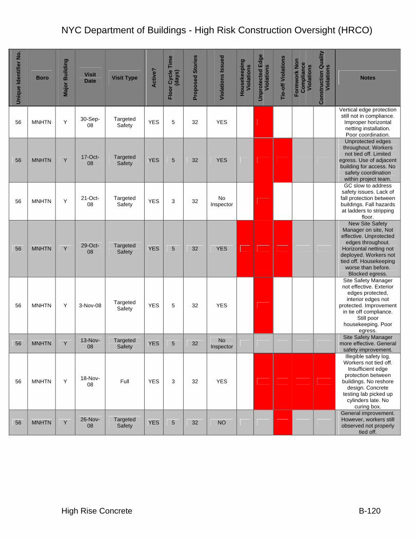
NYC Department of Buildings - High Risk Construction Oversight (HRCO)
High Rise Concrete B-120
Uni
que
Iden
tifie
r No.
Boro
Maj
or B
uild
ing
Visit Date Visit Type
Act
ive?
Floo
r Cyc
le T
ime
(day
s)
Prop
osed
Sto
ries
Viol
atio
ns Is
sued
Hou
seke
epin
g Vi
olat
ions
Unp
rote
cted
Edg
e Vi
olat
ions
Tie-
off V
iola
tions
Form
wor
k N
on
Com
plia
nce
Viol
atio
ns
Con
stru
ctio
n Q
ualit
y Vi
olat
ions
Notes
56 MNHTN Y 30-Sep-08
Targeted Safety YES 5 32 YES 1
Vertical edge protection still not in compliance.
Improper horizontal netting installation. Poor coordination.
56 MNHTN Y 17-Oct-08
Targeted Safety YES 5 32 YES 1 1
Unprotected edges throughout. Workers not tied off. Limited
egress. Use of adjacent building for access. No
safety coordination within project team.
56 MNHTN Y 21-Oct-08
Targeted Safety YES 3 32 No
Inspector 1
GC slow to address safety issues. Lack of fall protection between buildings. Fall hazards at ladders to stripping
floor.
56 MNHTN Y 29-Oct-08
Targeted Safety YES 5 32 YES 1 1 1
New Site Safety Manager on site, Not effective. Unprotected
edges throughout. Horizontal netting not
deployed. Workers not tied off. Housekeeping
worse than before. Blocked egress.
56 MNHTN Y 3-Nov-08 Targeted Safety YES 5 32 YES 1
Site Safety Manager not effective. Exterior
edges protected, interior edges not
protected. Improvement in tie off compliance.
Still poor housekeeping. Poor
egress.
56 MNHTN Y 13-Nov-08
Targeted Safety YES 5 32 No
Inspector Site Safety Manager
more effective. General safety improvement.
56 MNHTN Y 18-Nov-08 Full YES 3 32 YES 1 1 1 1
Illegible safety log. Workers not tied off.
Insufficient edge protection between
buildings. No reshore design. Concrete
testing lab picked up cylinders late. No
curing box.
56 MNHTN Y 26-Nov-08
Targeted Safety YES 5 32 NO 1
General improvement. However, workers still observed not properly
tied off.

NYC Department of Buildings - High Risk Construction Oversight (HRCO)
High Rise Concrete B-121
Uni
que
Iden
tifie
r No.
Boro
Maj
or B
uild
ing
Visit Date Visit Type
Act
ive?
Floo
r Cyc
le T
ime
(day
s)
Prop
osed
Sto
ries
Viol
atio
ns Is
sued
Hou
seke
epin
g Vi
olat
ions
Unp
rote
cted
Edg
e Vi
olat
ions
Tie-
off V
iola
tions
Form
wor
k N
on
Com
plia
nce
Viol
atio
ns
Con
stru
ctio
n Q
ualit
y Vi
olat
ions
Notes
57 MNHTN Y 13-Aug-08 Full YES 3 33 No
Inspector 1 1
Lack of formwork drawings. Using
adjacent building's formwork design. No
vertical formwork specifications. No
approved formwork drawings. Public and
worker safety hazards, lack of fencing,
construction barriers
57 MNHTN Y 15-Sep-08 Full YES 3 32 No
Inspector 1 Unprotected interior floor openings
57 MNHTN Y 15-Sep-08 Full YES 3 32 NO 1 No Reshore sequence
available
57 MNHTN Y 25-Sep-08
Targeted Safety YES 5 32 No
Inspector 1
Site Safety personnel not effective in
maintaining safety. Insufficient perimeter
protections. Unprotected edges
throughout site. Poor housekeeping
57 MNHTN Y 30-Sep-08
Targeted Safety YES 5 32 No
Inspector 1 1
Site Safety Manager not effective.
Unprotected edges. Netting not extended.
Limited tie off compliance.
57 MNHTN Y 17-Oct-08
Targeted Safety YES 5 32 YES 1 1
Site Safety Manager not effective.
Unprotected edges throughout. Workers
not tied off. Flammable tires used as adjacent
building protection. Obstructed egress.
Overall hazardous site conditions.
57 MNHTN Y 29-Oct-08
Targeted Safety YES 5 32 NO 1 1
Site Safety Manager reacting to HRCO visits. Continued
unprotected edges. Netting not fully
extended. Tires on adjacent roof. Debris. Workers not tied off.
BEST violation issuances needed.
57 MNHTN Y 6-Nov-08 Targeted Safety YES 5 32 YES 1 1
Improved exterior edge protection, interior
edges still unprotected. Continued tie off
noncompliance. Tie off violations not being enforced. Limited
cooperation of project team

NYC Department of Buildings - High Risk Construction Oversight (HRCO)
High Rise Concrete B-122
Uni
que
Iden
tifie
r No.
Boro
Maj
or B
uild
ing
Visit Date Visit Type
Act
ive?
Floo
r Cyc
le T
ime
(day
s)
Prop
osed
Sto
ries
Viol
atio
ns Is
sued
Hou
seke
epin
g Vi
olat
ions
Unp
rote
cted
Edg
e Vi
olat
ions
Tie-
off V
iola
tions
Form
wor
k N
on
Com
plia
nce
Viol
atio
ns
Con
stru
ctio
n Q
ualit
y Vi
olat
ions
Notes
57 MNHTN Y 13-Nov-08
Targeted Safety YES 5 32 No
Inspector
Site Safety Manager increasingly effective,
tie off compliance. Good perimeter
protection
57 MNHTN Y 28-Nov-08
Targeted Safety YES 5 32 No
Inspector
Major improvements. Good housekeeping, use of PFAS, fully-extended netting,
Protected fall hazards throughout
58 MNHTN Y 7-Nov-08 Full YES 3 27 No Inspector 1 1
No Formwork inspection performed. Column ties and shear
reinforcement not installed per plans.
Special inspector not able to catch
inconsistency. No reshore sequence
available.
58 MNHTN Y 22-Oct-08 Full YES 3 27 YES 1 1 1
Missing railing. Housekeeping. Missing some shoring towers.
58 MNHTN Y 24-Oct-08
Targeted Safety
Reinspection YES 3 27 NO Violations lifted from
previous visit
59 MNHTN N 30-Sep-08 Full NO
UNK (No
Activity)
10 No Inspector No Activity on Site
59 MNHTN N 2-Oct-08 Full YES 5 10 NO No finalized stripping
and reshoring sequence yet
60 MNHTN Y 30-Sep-08 Full YES 3 58 No
Inspector 1 1
No Wall form inspections performed.
Housekeeping and egress
60 MNHTN Y 16-Oct-08
Targeted Safety YES UNK 58 No
Inspector
61 MNHTN Y 11-Sep-08 - NO UNK UNK NO No activity, empty lot
62 MNHTN Y 30-Sep-08 Full YES 3 20 No
Inspector 1
No foundation wall inspection Log. No
formwork inspection logs. Wall forms removed prior to
knowledge of concrete strength
63 MNHTN Y 15-Sep-08 Full YES
UNK (Excavation)
13 NO 1
Improper concrete sampling. Concrete
Inspector not ACI Level 1 certified.

NYC Department of Buildings - High Risk Construction Oversight (HRCO)
High Rise Concrete B-123
Uni
que
Iden
tifie
r No.
Boro
Maj
or B
uild
ing
Visit Date Visit Type
Act
ive?
Floo
r Cyc
le T
ime
(day
s)
Prop
osed
Sto
ries
Viol
atio
ns Is
sued
Hou
seke
epin
g Vi
olat
ions
Unp
rote
cted
Edg
e Vi
olat
ions
Tie-
off V
iola
tions
Form
wor
k N
on
Com
plia
nce
Viol
atio
ns
Con
stru
ctio
n Q
ualit
y Vi
olat
ions
Notes
64 MNHTN Y 13-Aug-08 Full YES UNK 58 No
Inspector 1
No stamped or perforated set of
structural drawings. Public safety hazard,
open gate with fall hazard into excavation.
Fall hazards throughout. Protruding
rebar.
65 MNHTN NA 22-Sep-08
Targeted Safety NO UNK UNK NA Demolition Site
66 MNHTN NA 23-Sep-08 Not Active NO UNK UNK NO No Activity
67 MNHTN Y 8-Oct-08 Full YES 2 44 NO 1 1 1
Lack of Egress. Horizontal netting not
deployed fully. Multiple workers not tied off. Incorrect guardrail height. Cold bent
splices in columns and shearwalls
67 MNHTN Y 9-Oct-08 Targeted Engineering YES 2 44 YES 1 1 1
Improper column splices and cold-bent
embedded bars. Special inspector is PE,
qualified but not effective (code
violations present). Multiple unprotected
edges. Worker not tied off placing ribs in
formwork
68 MNHTN Y 23-Sep-08
DOB requested
visit for accident
YES UNK 31 YES 1
Steel Building, concrete pump pipe burst.
Partially-cured portions of incompletely poured
composite slab.
69 MNHTN N 24-Sep-08 Full YES UNK 14 YES 1 1 1 1
No Stamped formwork drawings. Contractor
not performing Inspections. Worker not tied off. SWO in place
presently due to adjacent building
movement. Partially-embedded slab dowels
bent. No Special Inspector logs. Slump
not in conformance with mix design.
Unprotected vertical netting opening
69 MNHTN N 7-Nov-08 Full YES UNK 14 No Inspector 1
Unit weight and air test not performed per
specifications. Air test uses chase meter instead of project-required pump test

NYC Department of Buildings - High Risk Construction Oversight (HRCO)
High Rise Concrete B-124
Uni
que
Iden
tifie
r No.
Boro
Maj
or B
uild
ing
Visit Date Visit Type
Act
ive?
Floo
r Cyc
le T
ime
(day
s)
Prop
osed
Sto
ries
Viol
atio
ns Is
sued
Hou
seke
epin
g Vi
olat
ions
Unp
rote
cted
Edg
e Vi
olat
ions
Tie-
off V
iola
tions
Form
wor
k N
on
Com
plia
nce
Viol
atio
ns
Con
stru
ctio
n Q
ualit
y Vi
olat
ions
Notes
70 BKLYN Y 28-Aug-08 Full NO UNK 13 No
Inspector
71 BKLYN Y 28-Aug-08 Full NO UNK UNK No
Inspector Stop Work Order In
Place. No personnel on site.
72 MNHTN Y 11-Sep-08 Full YES 3 20 YES 1 1
Improper shore post spacing, no reshore
specification. Engineer to issue note regarding formwork post spacing. Misplacement of rebar
stirrups
72 MNHTN Y 17-Sep-08 Reinspection YES 3 20 NO 1 Corrected steel issues.
72 MNHTN Y 17-Sep-08
Targeted Steel
reinspection YES 3 20 NO Steel issues corrected
72 MNHTN Y 23-Oct-08 Full YES 3 20 NO
72 MNHTN Y 27-Oct-08 Full YES 3 20 YES 1
Tie-off anchorages used on forming floor, pulled through holes in decking. Observed cold
bent partially-embedded steel
73 MNHTN N 23-Sep-08 Full YES 3 9 NO 1
No horizontal formwork drawings available.
Insufficient whaler size. Shop drawings without
engineer's stamp
74 MNHTN Y 29-Jul-08 Full YES 2 16 No
Inspector 1
74 MNHTN Y 25-Aug-08 Full YES 2 16 NO 1 1
Three beams with congestion, lack of
stirrup engagement and poor workmanship.
Column with unhooked ties. Column and beams field fixed.
Designers representatives onsite made field fix without
EOR notification. Fix is suspect.
75 MNHTN UNK 23-Sep-08
Targeted Safety NO UNK UNK No
Inspector No Activity
76 MNHTN UNK 20-Oct-08 Full YES
UNK (Below
Grade)
58 YES 1
77 MNHTN N 11-Sep-08
Targeted safety YES 5 11 YES 1 1 Limited use of fall
protection.
77 MNHTN N 17-Sep-08
Targeted safety YES 5 11 YES Adjacent property still
not protected

NYC Department of Buildings - High Risk Construction Oversight (HRCO)
High Rise Concrete B-125
Uni
que
Iden
tifie
r No.
Boro
Maj
or B
uild
ing
Visit Date Visit Type
Act
ive?
Floo
r Cyc
le T
ime
(day
s)
Prop
osed
Sto
ries
Viol
atio
ns Is
sued
Hou
seke
epin
g Vi
olat
ions
Unp
rote
cted
Edg
e Vi
olat
ions
Tie-
off V
iola
tions
Form
wor
k N
on
Com
plia
nce
Viol
atio
ns
Con
stru
ctio
n Q
ualit
y Vi
olat
ions
Notes
77 MNHTN N 23-Sep-08
Targeted safety YES 5 11 No
Inspector Improved site
conditions from last visit
77 MNHTN N 17-Oct-08 Full YES 3 11 No
Inspector 1 1
No site safety log. Missing stair guardrail.
Insufficient ladder length to upper deck. No special inspector reports. No approved shop drawings for this
floor. Concrete sampling not in
conformance with ASTM
78 MNHTN Y 20-Oct-08 Full NO
UNK (Excavation)
22 NO Excavation
79 MNHTN Y 22-Sep-08 Full YES 3 38 NO 1
No form inspection logs. Improper
fabrication of column ties
79 MNHTN Y 10-Nov-08
Targeted Safety YES 2 38 NO
79 MNHTN Y 12-Nov-08 Full YES 2 38 NO 1
Improper use of air test equipment. Not in conformance with
ASTM
80 MNHTN Y 12-Aug-08 Full YES 2 60
YES, Through
EOC 1 1
2 day cycle, some safety and ACI
violations observed, reported to Gus
81 MNHTN Y 17-Sep-08 Full Parti
ally 3 67 NO Excavation, but data recorded
82 MNHTN Y 15-Sep-08 Full Parti
ally UNK 60 NO No formwork design
available yet (still below grade) Site is idle
83 MNHTN N 6-Oct-08 Full YES UNK (precast)
12 YES 1
Reinforcing engagement issues. Unhooked stirrup in
grade beam. Controlled inspector not on site. No approved shop
drawings stamped by EOR.
83 MNHTN N 6-Oct-08 Full YES UNK (precast)
12 NO Steel issues corrected
84 MNHTN Y 24-Sep-08 Full YES 4 45 NO 1 1
Some vertical netting missing, housekeeping
issues. Limited form inspection logs, no vertical formwork
design. No special inspection reports. Observed typical
partially embedded bent column bars

NYC Department of Buildings - High Risk Construction Oversight (HRCO)
High Rise Concrete B-126
Uni
que
Iden
tifie
r No.
Boro
Maj
or B
uild
ing
Visit Date Visit Type
Act
ive?
Floo
r Cyc
le T
ime
(day
s)
Prop
osed
Sto
ries
Viol
atio
ns Is
sued
Hou
seke
epin
g Vi
olat
ions
Unp
rote
cted
Edg
e Vi
olat
ions
Tie-
off V
iola
tions
Form
wor
k N
on
Com
plia
nce
Viol
atio
ns
Con
stru
ctio
n Q
ualit
y Vi
olat
ions
Notes
84 MNHTN Y 11-Sep-08 Full YES 4 45 No
Inspector 1
Incomplete formwork drawings, no reshoring sequence. Incomplete formwork drawings of
upper floors
84 MNHTN Y 16-Oct-08 Full YES 3 45 YES 1 1
Improperly placed stirrups at 7th floor link
beam. Also fresh concrete testing not in
conformance with ASTM requirements.
Observed prior to BEST arrival, no violation issued
84 MNHTN Y 21-Oct-08 Full YES 3 45 NO Safety improvements
since last visit.
84 MNHTN Y 30-Oct-08
Targeted Safety YES 4 45 YES 1 1 1 1
Unprotected fall hazards. Horizontal
netting not extended. Most workers not tied
off. Housekeeping inadequate. Improperly
constructed work platform, no bracing.
Material stored on platform w/o bracing
84 MNHTN Y 5-Nov-08 Targeted Safety YES 4 45 No
Inspector 1
Improvement in most areas. However, most
workers not using PFAS
84 MNHTN Y 10-Nov-08
Targeted Safety YES 4 45 YES 1
Major lack of tie-off compliance. This is a recurring issue. Other
safety aspects are adequate
84 MNHTN Y 20-Nov-08 Full YES 3 45 No
Inspector 1 1 1
Embedded lanyards not installed. Horizontal
netting not fully deployed. Vertical
netting not tied down. Non-Conforming lap column splices >6".
Splicing issues identified last visit, not
resolved.
84 MNHTN Y 20-Nov-08
Targeted Safety YES 4 45 NO Improved Tie-off
compliance
84 MNHTN Y 28-Nov-08
Targeted Safety YES 4 45 No
Inspector 1 Workers generally using PFAS. One worker not tied off
84 MNHTN Y 26-Nov-09
Targeted safety YES 4 45 No
Inspector 1 Missing guardrails at hoist

NYC Department of Buildings - High Risk Construction Oversight (HRCO)
High Rise Concrete B-127
Uni
que
Iden
tifie
r No.
Boro
Maj
or B
uild
ing
Visit Date Visit Type
Act
ive?
Floo
r Cyc
le T
ime
(day
s)
Prop
osed
Sto
ries
Viol
atio
ns Is
sued
Hou
seke
epin
g Vi
olat
ions
Unp
rote
cted
Edg
e Vi
olat
ions
Tie-
off V
iola
tions
Form
wor
k N
on
Com
plia
nce
Viol
atio
ns
Con
stru
ctio
n Q
ualit
y Vi
olat
ions
Notes
85 BKLYN Y 18-Aug-08 Full YES 5 33 YES 1
No reshore sequence available, contractors experience only. Hard
hat violations. Per contractor engineer
gives approval prior to stripping floors. Poor chain of command
between Site Safety Manager and trades. Lack of respect B/W
trades and safety manager. Site Safety Manager unable to
control project, under pressure to keep low
profile
85 BKLYN Y 28-Aug-08
Targeted Engineering YES 5 33 No
Inspector 1 1
Field Modification and RFI log kept on site.
Verbal or written approvals needed for
execution of Field Modifications.
Observed some misplacement, brought
to attention of PEO
85 BKLYN Y 3-Sep-08 Full YES 5 33 YES 1 1 1 1
Column ties and stirrups not properly engaged at multiple locations. Unstable
timber posts between shoring tower and slab.
Worker standing on ladder top, not tied off.
Unprotected west elevation. Site Safety Manager not effective
85 BKLYN Y 10-Sep-08
Targeted Safety and
Engineering Steel
YES 5 33 YES 1 1
Observed additional steel issues, improper
leg lengths, stirrups not engaged to beam
bottom steel in transfer girder, 135 u-stirrup ends cut off. Multiple workers observed not
tied off. Shear wall steel ties not hooked
85 BKLYN Y 18-Sep-08
Targeted Steel
reinspection YES 5 33 NO 1
New Lather Crew and new Special Inspector.
Improved Housekeeping from last visit. Shearwall ties not
engaged

NYC Department of Buildings - High Risk Construction Oversight (HRCO)
High Rise Concrete B-128
Uni
que
Iden
tifie
r No.
Boro
Maj
or B
uild
ing
Visit Date Visit Type
Act
ive?
Floo
r Cyc
le T
ime
(day
s)
Prop
osed
Sto
ries
Viol
atio
ns Is
sued
Hou
seke
epin
g Vi
olat
ions
Unp
rote
cted
Edg
e Vi
olat
ions
Tie-
off V
iola
tions
Form
wor
k N
on
Com
plia
nce
Viol
atio
ns
Con
stru
ctio
n Q
ualit
y Vi
olat
ions
Notes
85 BKLYN Y 23-Oct-08
DOB Process NO 5 33 NA NA NA NA NA
Visit to Boro office confirms city is missing
full set of up-to-date construction
documents. Missing Arch/mech/civil/Founda
tion, and portions of Structural drawings. No perforated set on file in hard copy or microfilm.
Documents either misfiled or full set of
drawings never submitted.
85 BKLYN Y 23-Oct-08
Targeted Safety YES 5 33 YES 1 1 1
Safety personnel unable to identify or fix safety issues. Workers
not tied off. Missing vertical netting on each
floor. Inconsistent testing practices, not
ASTM standard concrete testing.
85 BKLYN Y 23-Oct-08
Targeted Safety YES 5 33 NO 1 1 1
Site Safety Manager ineffective. Unprotected edges throughout. Most
workers not tied off. Housekeeping. No
safety coordination or enforcement within
project team. Material storage
85 BKLYN Y 30-Oct-08
Targeted Safety YES 5 33 YES 1 1 1
Site Safety Personnel still not effective.
Exposed unprotected edges. No tie off
enforcement. Obstructed egress. No general improvement in
site safety. Improper wood post installation
at scaffold tower
85 BKLYN Y 3-Nov-08 Targeted Safety YES 5 33 YES 1 1 1
Site Safety Manager not effective.
Unprotected edges. Workers not tied off.
Obstructed exits. Materials stored at
building edge. Improper shore installation
(timber on end, this is a recurring problem at
this site). Project Manager and Site
Safety personnel have no effective methods to
provide safe working conditions

NYC Department of Buildings - High Risk Construction Oversight (HRCO)
High Rise Concrete B-129
Uni
que
Iden
tifie
r No.
Boro
Maj
or B
uild
ing
Visit Date Visit Type
Act
ive?
Floo
r Cyc
le T
ime
(day
s)
Prop
osed
Sto
ries
Viol
atio
ns Is
sued
Hou
seke
epin
g Vi
olat
ions
Unp
rote
cted
Edg
e Vi
olat
ions
Tie-
off V
iola
tions
Form
wor
k N
on
Com
plia
nce
Viol
atio
ns
Con
stru
ctio
n Q
ualit
y Vi
olat
ions
Notes
85 BKLYN Y 5-Nov-08 Targeted Safety YES 5 33 No
Inspector 1 1
SS Personnel have no control over site safety. Still inadequate edge
protection, but installing. No tie off
compliance. Blocked egress. 3rd floor Partial
SWO still in effect. Project team is not
making safety a priority.
85 BKLYN Y 7-Nov-08 Targeted Safety YES 5 33 No
Inspector 1 1
SS personnel effectiveness improved. Beginning installation of
more vertical netting. Most workers without
tie off . Partial SWO still in effect for 3rd floor
85 BKLYN Y 12-Nov-08
Targeted Safety YES 5 33 No
Inspector 1
SS Issues beginning to improve. Need 3rd floor
setback protection. Some worker still not tied off, but improved.
Most edges now protected
85 BKLYN Y 14-Nov-08
Targeted Safety YES 5 33 No
Inspector
Improved SS Personnel effectiveness.
Adequate vertical netting. Still no
overhead protection at 3rd floor. Workers
observed in violation of 3rd floor Partial SWO. Other SS conditions
improved
85 BKLYN Y 24-Nov-08
Targeted Safety YES 5 33 No
Inspector 1 1
SS Personnel still not effective. Inadequate
vertical netting. Unprotected interior
openings. Workers not tied off. Requested Revisit with BEST
85 BKLYN Y 25-Nov-08
Targeted Safety YES 5 33 YES 1 1
Site Safety Manager ineffective. Missing
edge protection. Many workers not tied off
85 BKLYN Y 28-Nov-08
Targeted Safety YES UNK 33 NO
Inadequate SS Logs. Adjacent building
protection noncompliance.
86 MNHTN Y 28-Aug-08
Targeted Safety YES UNK 30 No
Inspector

NYC Department of Buildings - High Risk Construction Oversight (HRCO)
High Rise Concrete B-130
Uni
que
Iden
tifie
r No.
Boro
Maj
or B
uild
ing
Visit Date Visit Type
Act
ive?
Floo
r Cyc
le T
ime
(day
s)
Prop
osed
Sto
ries
Viol
atio
ns Is
sued
Hou
seke
epin
g Vi
olat
ions
Unp
rote
cted
Edg
e Vi
olat
ions
Tie-
off V
iola
tions
Form
wor
k N
on
Com
plia
nce
Viol
atio
ns
Con
stru
ctio
n Q
ualit
y Vi
olat
ions
Notes
87 MNHTN Y 14-Aug-08 Full YES 4 76 No
Inspector 1 1
Timber on ends of towers. Missing Perimeter Edge
protection. Formwork Workmanship unstable.
Missing Reshoring Sequence. No
formwork inspection logs. Lateral shore
bracing not in conformance with
design. Unprotected edges on sixth floor
87 MNHTN Y 5-Sep-08 Targeted Safety YES 4 76 YES 1 1
Two Unprotected areas without vertical netting. Egress path
unclear. Incomplete site safety log. Engineer not
following stripping procedure outlined in project specifications.
87 MNHTN Y 5-Sep-08 Full YES 4 76 YES 1 1 1
Per engineer, project specification
requirements for form stripping are not
applicable and are to be revised. Workers not
tied off in elevator shaft, no edge
protection on forming floor. Premature form
stripping
87 MNHTN Y 10-Sep-08
Targeted Safety YES 3 76 No
Inspector
87 MNHTN Y 15-Oct-08 Full YES 3 76 No
Inspector 1 1 1
Workers not tied off. Premature lateral
bracing removal. No knowledge of concrete
strength prior to stripping. Concrete
tests not performed per ASTM
87 MNHTN Y 14-Nov-08 Full YES 3 76 NO 1 1
Missing railings on stairs. Insufficient use
of hard hats. No concrete inspector
onsite during stair pour.
88 MNHTN Y 13-Aug-08 Full YES 5 43 YES 1
Observed removal of PERI system lateral braces immediately below active casting floor. Design calls for reshoring at 14 days.
Unsafe stacked stringer installation. Unused lateral braces. Peri
Tower height exceeds design

NYC Department of Buildings - High Risk Construction Oversight (HRCO)
High Rise Concrete B-131
Uni
que
Iden
tifie
r No.
Boro
Maj
or B
uild
ing
Visit Date Visit Type
Act
ive?
Floo
r Cyc
le T
ime
(day
s)
Prop
osed
Sto
ries
Viol
atio
ns Is
sued
Hou
seke
epin
g Vi
olat
ions
Unp
rote
cted
Edg
e Vi
olat
ions
Tie-
off V
iola
tions
Form
wor
k N
on
Com
plia
nce
Viol
atio
ns
Con
stru
ctio
n Q
ualit
y Vi
olat
ions
Notes
88
MNHTN
Y 28-Aug-08
Targeted Engineering YES 5 43 YES 1 1
Observed improperly installed additional top
steel at interior columns and improperly installed
additional top steel at exterior wall. Controlled inspector stated he left
the site before rebar placement was
complete. Lateral bracing for shoring
directly below pouring floor was removed in the Northeast corner. GC requested bracing
be reinstalled.
88 MNHTN Y 30-Sep-08
Targeted Safety YES UNK 43 No
Inspector
89 MNHTN Y 27-Aug-08
Targeted Safety YES UNK 15 No
Inspector 1 1 Workers Not tied off on Forming Level
90 MNHTN Y 27-Aug-08
Targeted Safety YES UNK 34 No
Inspector 1 1
Limited ability of Site Safety Manager to
maintain control of site. Housekeeping violations and
unprotected edge violations previously
issued by BEST.
90 MNHTN Y 4-Sep-08 Full NO UNK 30 NO 1
Insufficient egress at casting floor. Formwork removal premature, not
in conformance with specifications. No
reshoring sequence or number of floors
specified
91 MNHTN Y 21-Aug-08 Full YES UNK 53 No
Inspector 1 1 1 1
No Cracking Specification. No logs
of formwork inspection. Improper column splice
installation. Per engineer, dowels to be drilled and epoxied for
proper splicing. Workers not tied off
installing formwork ribs. Improper cutting of
stirrup hooks

NYC Department of Buildings - High Risk Construction Oversight (HRCO)
High Rise Concrete B-132
Uni
que
Iden
tifie
r No.
Boro
Maj
or B
uild
ing
Visit Date Visit Type
Act
ive?
Floo
r Cyc
le T
ime
(day
s)
Prop
osed
Sto
ries
Viol
atio
ns Is
sued
Hou
seke
epin
g Vi
olat
ions
Unp
rote
cted
Edg
e Vi
olat
ions
Tie-
off V
iola
tions
Form
wor
k N
on
Com
plia
nce
Viol
atio
ns
Con
stru
ctio
n Q
ualit
y Vi
olat
ions
Notes
91 MNHTN Y 30-Sep-08 Full YES 4 53 No
Inspector 1 1 1 1
No Formwork inspection logs.
Workers not appropriately tied off, housekeeping, cannot keep up with stripping floor operations. No egress from working deck. Deck concrete
hosed down for workability. No stripping
sequences available. Sequencing not
specified in design. Uncontained material
storage.
92 MNHTN Y 12-Nov-08 Full YES 4 52 No
Inspector 1 1 1
Netting not secured at bottom. Housekeeping
on stripping floor. Improper post tie-offs at
edge
93 MNHTN Y 30-Sep-08 Full NO
UNK (Excavation)
48 No Inspector
94 MNHTN UNK 22-Sep-08 Full NO UNK 0 No
Inspector
Site Closed due to previous SWO, failure to protect public and
property

NYC Department of Buildings - High Risk Construction Oversight (HRCO)
High Rise Concrete B-133
Appendix B.2: Comparative Concrete Testing

NYC Department of Buildings - High Risk Construction Oversight (HRCO)
High Rise Concrete B-134
A preliminary audit of concrete property reporting was performed by the HRCO. Comparisons were made between results provided by the labs in question with results provided by an independent laboratory (The Port Authority of New York and New Jersey). The following assessments of five labs (designated A through E) were made by HRCO staff, and included some facilities visited during the Laboratory Quality assessment.
TESTING LAB: A
SITES: Site 87, 15-October 2008
Site 72, 12-November 2008
The following report provides comments regarding the sites sampled by the HRCO and Test Well on the date and site noted above.
Testing Methods
In accordance with ASTM C94 “Standard Specification for Ready-Mixed Concrete” concrete should be tested for unit weight and air content in conformance with ASTM C138 “Standard Test Method for Density (Unit Weight), Yield, and Air Content (Gravimetric) of Concrete” and ASTM C231 “Standard Test Method for Air Content of Freshly Mixed Concrete by the Pressure Method” respectively.
During the field sampling performed by this lab, it was observed that neither ASTM compliant unit weight testing, nor any surrogate unit weight test method was performed. Air testing was performed using the chase air indicator which is not an ASTM standard, and as noted by the manufacturer of the product, does not qualify as a substitute for the pressure or volumetric method prescribed by ASTM. Test reports do not indicate the test methods by which air content and unit weight were obtained, although the report suggests full ASTM conformance by making reference to ASTM C94.
Reporting Of Test Results
Compressive strength test results, as prescribed by ASTM C39 “Standard Test Method for Compressive Strength of Cylindrical Concrete Specimens”, should be reported at the age of 24 hours, 3 days, 7 days, 28 days, and 90 days within their respective tolerances unless otherwise required in the project specifications. Compressive strength test results of individual cylinders reported for both sites do not comply with the age requirements set forth in ASTM C39. In the case of Site 87, samples prepared on 15-Oct. 2008, were tested at an age of 37 days, and no testing was performed at 28 days. The Site 72 samples prepared on 12-Nov. 2008 were tested at 10 days, 29 days and 37 days. There is a possibility that the 29 day test result is within

NYC Department of Buildings - High Risk Construction Oversight (HRCO)
High Rise Concrete B-135
tolerance, although the time of day at which the samples were prepared and tested is not provided.
Lab test reports indicate fracture pattern type 5. This fracture pattern is typically found in tests performed with un-bonded caps. When this type of fracture occurs during testing, ASTM C39 recommends continuing compressing the specimen until a different fracture is achieved. Therefore, these results further suggest this lab’s non-conformance with ASTM standards.
Test Results
The following table presents the test results for the sites sampled by the HRCO and Lab A. Test results were extracted from reports provided by the Department of Buildings’ independent laboratory, The Port Authority of New York and New Jersey.
Table 1. Summary of Concrete Compressive Strength Results at Site 87
Site Location
(date)
Testing Agency ID
Air
(%)
UW
(lbs/cuft)
Specified
strength
(psi)
Age (days)
Average f’c
(psi)
% based on 28 day strength
6 7450 70 Port Authority
Site 87 1.6 152.8 28 10665 100
7 7630 NA
37 11060 NA set 3 2.2 152
56 11105 NA
7 8270 NA
37 11940 NA set 5 2.0 151
56 11990 NA
7 8370 NA
37 11460 NA
Site 87
(10/15/2008) Lab A
set 8 2.2 152
9000
56 12190 NA

NYC Department of Buildings - High Risk Construction Oversight (HRCO)
High Rise Concrete B-136
Table 2. Summary of Concrete Compressive Strength Results at Site 72
Site Location
(date)
Testing Agency ID
Air
(%)
UW
(lbs/cuft)
Specified
strength
(psi)
Age (days)
Average f’c
(psi)
% based on 28 day strength
7 4800 75 Port Authority
Site 72 5 148.8 28 6370 100
10 4850 NA
29 5280 100
Site 72
(10/27/2008) Lab A set 1 3 149
5000
37 5440 NA
General Comments:
• Strength development rends are typical • The Site 87 strength test results for specimens at 6 and 7 days, are similar for both
testing agencies. • At Site 72, strength development rate of the concrete specimens appears lower than
those sampled by HRCO engineers. The rate at which concrete develops strength is related to the mix proportions, curing time and curing temperature.
TESTING LAB: B
SITES: Site 56, 21-October 2008
Site 41, 23-October 2008
Site 14, 5-November 2008
The following report provides comments regarding the sites sampled by the HRCO and Laboratory B on the date and site noted above.

NYC Department of Buildings - High Risk Construction Oversight (HRCO)
High Rise Concrete B-137
Testing Methods
In accordance with ASTM C94 “Standard Specification for Ready-Mixed Concrete” concrete should be tested for unit weight and air content in conformance with ASTM C138 “Standard Test Method for Density (Unit Weight), Yield, and Air Content (Gravimetric) of Concrete” and ASTM C231 “Standard Test Method for Air Content of Freshly Mixed Concrete by the Pressure Method” respectively.
HRCO engineers were present at three sites where this lab generated an “Inspection and Testing of Concrete Report” which summarized information related to the concrete placement on a specific date and the strength of the corresponding specimens. HRCO engineers observed test methods utilized by this lab during their sampling of fresh concrete properties, and observed they failed to perform unit weight testing. Furthermore, air content testing was performed using the chase air indicator, which is not an ASTM standard and, does not qualify as a substitute for the pressure or volumetric method prescribed by ASTM.
Lab test reports produced by lab B do not indicate the test methods by which air content and unit weight were obtained, or if test methods were performed in accordance to the standards recommended by ASTM C94.
Reporting Of Test Results
Compressive strength test results should be reported in accordance with ASTM C 39 “Standard Test Method for Compressive Strength of Cylindrical Concrete Specimens”. The standard indicates that the fracture pattern produced by compressive testing should be included in the test report. The reports produced by this lab indicate the fracture pattern for all cylinders, even those not subjected to compressive testing, is type “A”, suggesting this classification is a “default” pattern on the spreadsheet used to generate the report. Reporting in this manner raises concerns regarding the accuracy of lab B’s test reporting.

NYC Department of Buildings - High Risk Construction Oversight (HRCO)
High Rise Concrete B-138
Test Results
The following table presents the test results for the sites sampled by HRCO engineers and Lab B. Test results were extracted from reports provided by the Department of Buildings’ independent laboratory, The Port Authority of New York and New Jersey.
Table 1. Summary of Concrete Compressive Strength Results at Site 56
Site Location
(date)
Testing Agency ID air
(%)UW
(lbs/cuft)
Specified strength
(psi)
Age (days) f'c(psi)
% based on 28 day strength
2 2650 43
7 4355 71
14 4820 79 Port Authority 1.0 146
28 6120 100
7 4685 77 52AS 3.0 146
28 6117 100
7 4415 74
Site 56 (10/21/2008)
Lab B
52BS 3.5 146
5950
28 5963 100

NYC Department of Buildings - High Risk Construction Oversight (HRCO)
High Rise Concrete B-139
Table 2. Summary of Concrete Compressive Strength Results at Site 41
Site Location
(date)
Testing Agency ID air (%)
UW (lbs/cu
ft)
Specified strength
(psi)
Age (days) f'c(psi)
% based on 28 day
strength
7 4570 74 Port Authority
1.5 150 28 6176 100
7 4980 80 1S 3.0 153
29 6250 100
7 4790 79 2S 2.4 155
28 6043 100
7 4920 76
Site 41
(10/23/2008) Lab B
3 2.7 153
5000
28 6453 100

NYC Department of Buildings - High Risk Construction Oversight (HRCO)
High Rise Concrete B-140
Table 3. Summary of Concrete Compressive Strength Results at Site 14
Site Location
(date)
Testing Agency ID air (%) UW
(lbs/cuft)
Specified strength
(psi)
Age (days) f'c(psi)
% based on 28 day
strength
2 6510 NA
7 8420 NA Port
Authority 3.3 152
28 NA
7 9690 81
14 10780 91 10S 1.9 150
28 11910 100
7 8580 75
14 9830 86
Site 14 (11/5/2008)
Lab B
11S 1.5 153
8000
28 11400 100
General Comments:
• Trends in strength development and strength levels are similar for both testing agencies

NYC Department of Buildings - High Risk Construction Oversight (HRCO)
High Rise Concrete B-141
TESTING LAB: C
SITE: Site 16, Manhattan 29-October, 2008.
The following report provides comments regarding the sites sampled by the HRCO and Laboratory C on the date noted above.
Testing Methods
In accordance with ASTM C94 “Standard Specification for Ready-Mixed Concrete” concrete should be tested in for unit weight and air in conformance to ASTM 138 “Standard Test Method for Density (Unit Weight), Yield, and Air Content (Gravimetric) of Concrete” and ASTM 231 “Standard Test Method for Air Content of Freshly Mixed Concrete by the Pressure Method” respectively.
During the field sampling performed by HRCO engineers at Site 16, it was observed that laboratory staff did not perform ASTM compliant unit weight or air content testing. Test reports do not indicate the test methods by which air content and unit weight were obtained and reported.
Reporting of Test Results
Compressive strength test results should be reported in accordance with ASTM C 39 “Standard Test Method for Compressive Strength of Cylindrical Concrete Specimens”. Strength test results reported by this lab do not list the type of fracture pattern as prescribed by ASTM C39. This particular item is of importance because cylinders tested with unbonded caps are likely to exhibit varying fracture patterns, and an analysis of these patterns by the engineer may indicate if the cylinder’s ultimate strength has been appropriately reported.
ASTM C39 also requires that specimen size, loaded area of cylinder, and load levels be reported on standard laboratory reports. Test reports provided by lab C failed to provide this information.
Test Results
The following table presents the test results for the site sampled by HRCO engineers and Laboratory C. Test results were extracted from reports provided by the Department of Buildings’ independent laboratory, The Port Authority of New York and New Jersey.

NYC Department of Buildings - High Risk Construction Oversight (HRCO)
High Rise Concrete B-142
Table 1. Summary of Concrete Compressive Strength Results at Site 16
Site Location
(date)
Testing Agency
Field ID Lab ID air
(%) UW
(lbs/cuft)Age
(days) f'c (psi)
% based on 28 day
strength
2 3170 58
7 3810 70 Port
Authority 8.0 140
28 5435 100
7 3970 75 175
1819-1822
4.0 141 28 5260 100
7 4490 69 178
1830-1833
4.5 145 28 6490 100
Site 16
(10/29/2008)
Lab C
180 1838-1840
4.5 144 28 6010 100
General comments:
• Trends of the concrete strength development appear similar for testing performed by both laboratories
NYC Department of Buildings - High Risk Construction Oversight (HRCO)
High Rise Concrete B-143
TESTING LAB: D
SITES: Site 67, 10-October 2008
Site 4, 15-October 2008
Site 79, 12-November 2008
The following report provides comments regarding laboratory D test sites observed by the HRCO on the dates noted above.
Testing Methods
Reports prepared by Lab D indicate that unit weight and air content testing should be performed in accordance to ASTM C138 “Standard Test Method for Density (Unit Weight), Yield, and Air Content (Gravimetric) of Concrete”, and ASTM C231 “Standard Test Method for Air Content of Freshly Mixed Concrete by the Pressure Method” respectively. During the field sampling performed by HRCO engineers at these sites, it was observed that Lab D did not perform any ASTM-compliant unit weight testing. Furthermore, air content testing was performed using the chase air indicator, which is not an ASTM standard, and does not qualify as a substitute for the pressure or volumetric method prescribed by ASTM.
Reporting Of Test Results
Compressive strength test results, including fracture pattern, must be reported in accordance with ASTM C39 “Standard Test Method for Compressive Strength of Cylindrical Concrete Specimens”. Strength test results reported by this laboratory do not list the type of fracture pattern as prescribed by ASTM C39. This particular item is of importance because cylinders tested with un-bonded caps are likely to exhibit varying fracture patterns, and an analysis of these patterns by the engineer may indicate if the cylinder’s ultimate strength has been appropriately reported.
Test Results
The following table presents the test results for the sites sampled by HRCO engineers and laboratory D. Test results were extracted from reports provided by the Department of Buildings’ independent laboratory, The Port Authority of New York and New Jersey

NYC Department of Buildings - High Risk Construction Oversight (HRCO)
High Rise Concrete B-144
Table 1. Summary of Compressive Strength Test Results at Site 67
Site Location
(date)
Testing Agency
Specified strength
(psi) ID Air
(%)
Unit Weight
(lbs/cuft)
Age (days)
Average f'c (psi)
Percentage of 28 day
f’c
2 4350 42
7 7395 72 Port Authority Site 67 2.8 149.6
28 10325 100
7 8490 82 3250E 2.5 149.9
28 10417 100
7 8435 86 3250B 2.25 149.9
28 9830 100
7 7980 85
Site 67 (10/10/2008)
Lab D
7000
3250G 2.0 149.9 28 9440 100

NYC Department of Buildings - High Risk Construction Oversight (HRCO)
High Rise Concrete B-145
Table 2. Summary of Compressive Strength Test Results at Site 4
Site Location
(date)
Testing Agency
Specified strength
(psi) ID Air (%)
Unit Weight
(lbs/cuft)
Age (days)
Average f'c (psi)
Percentage of 28 day f’c
6 8630 67 Port Authority
Site 4 1.6 149.6 28 12970 100
7 6360 73 3304A 2.0 149.9
28 8703 100
7 6480 75 3304B 2.25 149.9
28 8640 100
7 6230 75
Site 4 (10/15/2008)
Lab D
8300
3304C 2.5 149.9 28 8340 100
Table 3. Summary of Compressive Strength Test Results at Site 79
Site Location
(date)
Testing Agency
Specified
strength (psi)
ID Air (%) Unit
Weight (lbs/cuft)
Age (days)
Average f'c (psi)
Percentage of 28 day f’c
2 5220 NA
7 10220 NA Port Authority Site 79
4.1 148.0
28 NA
1 3580 NA
7 7590 NA
Site 79
(11/12/2008)
Lab D
9000
3498 2.0 154.3
28 NA
• Port Authority and laboratory D strength test results exhibit similar trends and strength development

NYC Department of Buildings - High Risk Construction Oversight (HRCO)
High Rise Concrete B-146
• Average compressive strength results provided by this lab, corresponding to sites 79 and 4, were consistently lower than those tested by the Port Authority. The approximate difference in average strength at 28 days was 35%.
• Strength levels, based on a percentage of the 28 day strength, were generally 10% lower for the results reported by lab D when compared to the data provided by the Port Authority.

NYC Department of Buildings - High Risk Construction Oversight (HRCO)
High Rise Concrete B-147
TESTING LAB: E
SITE: Site 85, 23-October 2008
The following report provides comments regarding the sites visited by the HRCO and Laboratory E on the dates noted above. HRCO did not sample concrete from this site, but specimens from which strength results were obtained were provided to the HRCO by lab E and the Department of Buildings’ independent laboratory, The Port Authority of New York and New Jersey.
Testing Methods
ASTM C94 “Standard Specification for Ready-Mixed Concrete” dictates proper test procedures for concrete testing. According to ASTM C94, unit weight and air content testing should be performed in conformance to ASTM C138 “Standard Test Method for Density (Unit Weight), Yield, and Air Content (Gravimetric) of Concrete” and ASTM C231 “Standard Test Method for Air Content of Freshly Mixed Concrete by the Pressure Method” respectively. At this site, lab E did not perform any ASTM-compliant unit weight testing. Furthermore, air content testing was performed using the chase air indicator, which is not an ASTM standard, and does not qualify as a substitute for the pressure or volumetric method prescribed by ASTM.
Lab test reports produced by this lab do not indicate the tests methods by which air content and unit weight were obtained, or if test methods were performed in accordance to the standards recommended by ASTM C94.
Reporting Of Test Results
Compressive strength test results should be reported in accordance with ASTM C 39 “Standard Test Method for Compressive Strength of Cylindrical Concrete Specimens”. Strength test results reported by ASC do not list the type of fracture pattern as prescribed by ASTM C39. This particular item is of importance because the analysis of the fracture pattern by the engineer may indicate if the cylinder’s ultimate strength has been appropriately reported.
Comparison of Test Results
Laboratory E reported on 23-October 2008, that twenty-five (25) 4”x8” cylinders were set aside for the HRCO including fourteen (14) cylinders specified at 7000 psi, and eleven (11) cylinders specified at 9000 psi.
Upon returning to the site, the HRCO found only three of the reported eleven 4”x8” 9000 psi cylinders. Table 1 compares the results of concrete testing as reported by lab E and the HRCO’s independent laboratory. The compressive strength results provided by this lab are not consistent with cylinder dimensions reported in the field. Data suggests lab E either failed to accurately field-report cylinder dimensions, or fabricated compressive strength data for non-

NYC Department of Buildings - High Risk Construction Oversight (HRCO)
High Rise Concrete B-148
existent cylinders. It is unknown if lab E possesses the equipment necessary to load a specimen to 360 kips.
Table 1. Reported Cylinder Properties
Reporting Laboratory
Test Age
(Days)
Reported Dimensions of Cylinder
(in.x in.)
Area
(in2)
Load
(lbs)
Strength
(psi)
Lab E* 28 6x12** 28.27 360000 12730
HRCO 28 4x8 12.57 156600 12460
*Data obtained from laboratory report dated 23-October 2008-Specimen 81G
**Cylinder size contrary to that documented in field report
Test Results
The following table presents the test results for the sites sampled by lab E, and provided to the HRCO. Test results were extracted from reports provided to the Department of Buildings.
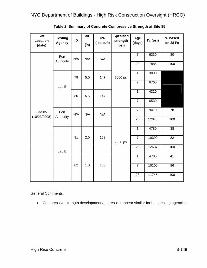
NYC Department of Buildings - High Risk Construction Oversight (HRCO)
High Rise Concrete B-149
Table 2. Summary of Concrete Compressive Strength at Site 85
Site Location
(date)
Testing Agency ID
air
(%)
UW (lbs/cuft)
Specified strength
(psi)
Age (days) f'c (psi) % based
on 28 f’c
7 6330 80 Port Authority
N/A N/A N/A 28 7885 100
1 3890 79 5.0 147
7 6760
1 4320 Lab E
80 5.5 147
7000 psi
7 6530
7 9410 78 Port Authority
N/A N/A N/A 28 12070 100
1 4780 38
7 10390 82 81 2.0 153
28 12637 100
1 4780 41
7 10100 86
Site 85 (10/23/2008)
Lab E
82 1.0 153
9000 psi
28 11745 100
General Comments:
• Compressive strength development and results appear similar for both testing agencies.

NYC Department of Buildings - High Risk Construction Oversight (HRCO)
High Rise Concrete B-150
Appendix B.3: Laboratory Quality Observations

NYC Department of Buildings - High Risk Construction Oversight (HRCO)
High Rise Concrete B-151
After assessing the testing procedures and results from a number of concrete testing laboratories, the HRCO team concluded that laboratory quality varies greatly and that continued monitoring of the laboratory’s ability to perform ASTM-compliant testing is well warranted. The following observations of three labs (designated D, E, and F) were made by HRCO staff in January 2008.
Testing Lab D The following observations were compiled during an HRCO team visit to Testing Laboratory D conducted on January 22, 2008:
• Lab employs at least three ACI certified strength testing technicians
• Observed organized curing room and laboratory record-keeping.
• Lab utilizes automated testing equipment for application of load.
• Insufficient record keeping in regards to reusable neoprene caps.
• Test results fail to record compression failure mode. Lack of notation not in conformance with ASTM C31.
Testing Lab E The following observations were compiled during an HRCO team visit to Testing Laboratory E conducted on January 22, 2008:
• Cylinder de-molding occurred four days after delivery, timing not in conformance with specifications of ASTM C31.
• Cylinders only partially immersed in water, not in conformance with specifications of ASTM C31 (Figure B.3.1).
• Lack of proper water circulation in curing trough. Temperature of water in trough is 10° higher than allowed by ASTM C31.
• Lack of certified personnel (ACI strength testing technician)
• Compression equipment not automated, technician must indirectly control loading rate.
• Lack of humidity sensor in curing room.
• Insufficient equipment available to properly measure core or cylinder dimensions.
• Final reports lack reference to testing methods or ASTM standards.

NYC Department of Buildings - High Risk Construction Oversight (HRCO)
High Rise Concrete B-152
• Test results fail to record compression failure mode. Lack of notation not in conformance with ASTM C31.
Figure 1: Improper Cylinder Curing Procedures, Some Cylinders Partially Immersed
Testing Lab F The following observations were compiled during an HRCO team visit to Testing Laboratory F conducted on January 21, 2008:
• No ACI certified strength testing technicians present during visit.
• Curing room appeared to contain adequate temperature and moisture conditions and controls.
• Cylinder storage not organized, cylinders stacked on top of each other.
• Records indicate that testing machines were recently calibrated, however, the loading system is not automated, and the rate of loading must be controlled manually.
• Unbonded neoprene cap records indicate some caps were used more than One hundred times, exceeding provisions of ASTM C1231 / C1231M – 09: Standard Practice for Use of Un-bonded Caps in Determination of Compressive Strength of Hardened Concrete Cylinders.

NYC Department of Buildings - High Risk Construction Oversight (HRCO)
High Rise Concrete B-153
Test results fail to record compression failure mode. Lack of notation not in conformance with ASTM C31.

NYC Department of Buildings - High Risk Construction Oversight (HRCO)
Cranes and Hoists C-1
C. Cranes and Hoists C.1 INTRODUCTION This chapter summarizes the crane and hoist assessment, and includes this introduction (Section 1), aspects of crane safety (Section 2), observations completed during assessment period (Sections 3), DOB process review and industry outreach (Section 4) and a summary of the recommendations (Section 5). Crane Tech Solutions and Patuxent Engineering Group principally authored the crane and hoist sections of this chapter, respectively.
The overriding themes of these recommendations are the importance of knowledgeable and experienced workers (both industry and regulatory), promotion of oversight and modernization of equipment.
From all sources available to the HRCO: historical studies; meetings with industry, manufacturers and DOB; and, our own experience, the most important factor for safe crane operations is having knowledgeable and experienced workforce. Recommendations for crane erection, climbing and disassembly, third party inspections, maintenance & repair all serve to increase the level of knowledge and experience available to the crane workforce during critical operations.
Promotion of oversight seeks to make DOB more efficient in its role. Recommendations such as Tracking Mobile Cranes (to improve the ability of DOB to observe these machines), Third Party Inspections (which remove the day-to-day resource obligations for inspections from DOB) and Maintenance & Repair (which allows tracking of critical crane repairs) all streamline DOB’s ability to enforce regulations. Many of the issues identified by the HRCO are already addressed by existing regulations; what is needed is the ability to efficiently enforce the regulations and identify the minority of individuals and companies that are habitually out of conformance.
Modernization of equipment will provide many benefits. In general the recommendations do not specifically call for changes in equipment, but many of the issues addressed by the recommendations would be improved with a newer fleet. For example, a number of marginal rigging practices, such as those associated with “riding a load” (in which a worker must stand on a piece of equipment while it is being lifted), would be obviated by employing newer tower cranes.
These themes are reflected in recommendations regarding Crane & Derricks Unit (C&D) operations, and in many ways have already been taken up by C&D following a recent restructuring. For example, C&D is working to enhance staff training in many ways including additional hands-on training for field inspectors and exposing plan examiners to field inspections. Also, C&D has been working to improve and streamline

NYC Department of Buildings - High Risk Construction Oversight (HRCO)
Cranes and Hoists C-2
its approach to oversight with initiatives such as formalizing Standard Operating Procedures and development of a database that will ultimately be accessible by the public.
In additional to assessing crane operations, the HRCO team identified a gap in regulation of hoist equipment in NYC. There is potential for significant accidents and injuries associated with these machines. Therefore the HRCO included assessments of hoist machines as a subset of the crane study.

NYC Department of Buildings - High Risk Construction Oversight (HRCO)
Cranes and Hoists C-3
C.2 Aspects of Crane Safety
Accident Causes
Crane safety is an important component of overall construction safety. The Occupational Safety and Health Administration (OSHA) compiles national data on both general construction and crane-specific accidents. Studies of the OSHA data identify crane accidents to be associated with 8%1 to 16.1%2 of construction fatalities.
The variation is not surprising; as important as crane operations are, the available national crane accident data is far from complete. In the first place, many crane accidents go unreported. For those that are investigated by a regulatory authority, there is no consistent, master database of crane accident records across the country. For the most part, studies of historical data require in-depth review of actual accident reports to identify causal factors. Numerous studies of OSHA data have endeavored to identify leading factors that cause accidents, some of the most notable lists of accident causes are summarized in Table C.1.1.
Center to Protect Worker’s Rights (CPWR)3 Source: Selected OSHA records for 1984 - 1994
Sheppard et. al. (2000)4 Source: Selected OSHA records for 1984 - 1994
Construction Industry Research and Policy Center (CIRPC)1 Source: OSHA Records for 1997-2003
Cause Percent Cause Percent Cause Percent
Electrocution 39% Electrocution 36% Struck by load 32%
Assembly/Dismantling 12% Fall of load 10% Electrocution 27%
Boom Buckling 8% Overturn 7% Assembly/disassembly 12%
Upset/overturn 7% Dismantling 6% Failure of boom/cable 12%
Rigging 7% Caught b/n counterweight
3% Tip over 11%
Other 27% Other 38% Struck by cab/counterweight
3%
Falls 2%
Table C.1.1: Summary of Crane Accident Study Findings
1 Beavers, J.E. et.al., Crane-Related Fatalities in the Construction Industry, University of Tennessee Construction Industry Research and Policy Center (CIRPC), March, 2005.
2 Neitzel, R.L., et.al., A Review of Crane Safety in The Construction Industry, Applied Occupational and Environmental Hygiene 16(12), 2001.
3 McCann, M., et.al., Crane-Related Deaths in Construction and Recommendations for Their Prevention, The Center for Construction Research and Training (CPWR).
4 Shepard, G.W., et.al., Crane Fatalities – A Taxonomic Analysis, Safety Science 36(2), 2000.

NYC Department of Buildings - High Risk Construction Oversight (HRCO)
Cranes and Hoists C-4
Similarly, a 2009 study from the Technion-Israel Institute of Technology is a first step in an attempt to determine, with greater accuracy, factors that influence crane safety. This first phase of the study involved a detailed survey of crane experts. Twenty one primary factors that effect crane safety were identified and weighted.
Figure C.1.1: Weighting of Factors that Affect Crane Safety.
These factors have varying degrees of relevance to the New York crane environment. The most significant point being that the study of causes of crane accidents is still in its infancy and that there are a wide range of factors that cause accidents. There is only a general understanding of leading causes, and little clear guidance on factors and practices that would best reduce accidents. Perhaps the most common theme is the role of human error in a majority of accidents and the related importance of worker knowledge and experience to avoid failures.
Consequence and Impact
What will be termed high-consequence crane accidents are of particular concern for the HRCO study. High-consequence crane accidents are generally associated with tower and large mobile cranes, and are qualitatively differentiated as having a high potential for multiple fatalities (including bystanders) and significant destruction of property.
Based on HRCO analysis of historic NYC accident data, between January 2006 and December 2008, 75% of fatalities and 55% of injuries were associated with just three

NYC Department of Buildings - High Risk Construction Oversight (HRCO)
Cranes and Hoists C-5
major tower crane failures (Table C.1.2). One failure in particular (March 15, 2009 51st failure) accounted for 58% and 42% of fatalities and injuries, respectively.
Date Description Injuries Fatalities
Sept. 29, 2006 Tower crane failure during dismantling.
5 0
March 15, 2008 Tower crane collapse.
22 7
May 30, 2008 Tower crane collapse.
2 2
Totals for high-consequence (% of all causes)
3 accidents (13%)
29 (56%)
9 (75%)
Total all causes 23 accidents 52 12
Table C.1.2: NYC Crane injuries and fatalities for three year period, January 2006 – December 2008.
The high-consequence of accidents involving tower and large mobile cranes is a function of the size of the machines and magnitude of load that they are capable of lifting. Typical tower and large mobile cranes have impact diameters of hundreds of feet (based on the height and reach of the cranes). The equipment itself typically weighs tens of thousands of pounds and is capable of lifting hundreds of thousands of pounds.

NYC Department of Buildings - High Risk Construction Oversight (HRCO)
Cranes and Hoists C-6
Figure C.1.2 shows an impact zone with a 200 foot radius. Within this zone are dozens of buildings and on the order of 1,000 people. The hypothetical impact zone is shown for an actual past crane location, and one at which there was a significant failure during dismantling of the crane.
As is the nature of most high-consequence events, the probability of major crane accidents is low. Along with low probability of occurrence, there is also a low probability of repetition of cause. The HRCO is not aware of any authoritative set of data of high-consequence crane failures. An informal list compiled by the HRCO identified that after assembly, climbing and dismantling; there was little repeatability in the source of the accidents.
Figure C.1.2: Impact Zone of a Tower Crane Collapse.
The combination of low probability and high variability (and thus uncertainty) of causes of high-consequence crane accidents presents a challenge in promoting safety. Construction risks which are closely tied to a single cause can be addressed by targeted procedures. The variable nature of crane risk requires a broader range of controls to introduce a level of redundancy.

NYC Department of Buildings - High Risk Construction Oversight (HRCO)
Cranes and Hoists C-7
C.3 Site Observations
Cranes
A total of 182 site visits were completed by HRCO crane field teams between July 2008 and January 2009. Of these, there was no crane or no observable crane operations at 14 sites, resulting in 168 actual observations of crane equipment and operations, carried out on 104 individual pieces of equipment (some cranes were observed multiple times). Table C.3.1 provides the type and number of the various types of cranes visited.
The crane team typically sent out one senior inspector to visit each site. The team performed full and targeted visits. Targeted site visits were limited to specific crane safety issues. Full site visits included a broad spectrum of items related to crane equipment and operation. A DOB Cranes and Derricks Unit inspector accompanied the HRCO observation teams during a substantial number of the early site visits. The HRCO completed the later visits alone and reported any potential violating conditions directly to C&D. Observations from site visits were recorded on to standardized Location Reports.
The HRCO team essentially observed all available tower crane sites during the period of the study. There may have been a small number of tower cranes that were either being just brought out of or into operation at beginning or end of the study that were not observed.
Type of Crane Quantity Observed
Quantity with Safety Issue
Tower 42 27 (68%) Rubber Tired Mobile 28 11 (39%) Crawlers 20 7 (35%) Knuckle Boom 6 5 (83%) Mast Climbers 5 5 (100%) Other 3 2 (67%)
Total 104 57 (56%)
Table C.3.1 – Types of cranes visited
The majority of mobile cranes were observed in September and October 2008. Forty jobsites were chosen randomly from the outstanding list of permitted cranes. Jobsites in the Bronx, Brooklyn, Manhattan and Queens where selected. Additional mobile crane observations were made based on particular issues of interest.

NYC Department of Buildings - High Risk Construction Oversight (HRCO)
Cranes and Hoists C-8
Hoists
A total of 99 site visits were completed by the HRCO hoist team between July 2008 and January 2009. Because of the relatively little oversight currently applied to hoist machines, hoist sites were selected on a random basis and captured a range of parameters including type (material only and personnel and material hoists), union and non-union operation and configuration of back structure.
Nine of the hoist site observations were targeted to hoist machine owner’s shops and storage yards as described in the recommendation for Off-site Controls.

NYC Department of Buildings - High Risk Construction Oversight (HRCO)
Cranes and Hoists C-9
C.4 DOB Process Review and Industry Outreach
DOB Process Review
The HRCO team interviewed all of the Cranes and Derricks Unit’s inspectors (through February, 2009) to determine their respective strengths and weaknesses as well as to determine their views regarding the unit and industry. The HRCO crane team also observed inspectors in the field performing their inspection tasks.
In addition to the inspectors, the HRCO crane team interviewed the plan examiners and members of the administrative staff. The purpose of these interviews was to assess the various procedures of the Unit and the functioning of the staff.
Industry Outreach
An important aspect of the overall assessment was to include the various perspectives of the stakeholders in the crane area. To do this, the HRCO moderated three meetings with the NYC industry. The attendees included: crane owners, users, professional engineers, manufactures, union representatives, operators and DOB personnel. The HRCO presented their proposed recommendation and sought feedback from the group. These meeting were valuable in shaping the final recommendations.
DOB and the HRCO also wanted to include other groups that may have a viewpoint for the recommendations. As such, DOB moderated a meeting with other regulatory bodies to share ideas and determine possible directions for the jurisdiction. In addition, the HRCO moderated two meetings with manufacturers to outline the possible recommendations. These groups were also critical in the final development of this report.
There were three new laws enacted in the fall of 2008 to primarily tower cranes. One of these laws required the members of tower crane crews (assembly, jumping and dismantling) to attend a 30 hour course. The HRCO attend a four hour portion of one course to ascertain the curriculum and the class room environment. In addition, the material for two other courses was reviewed for content.
New York State invited the HRCO to attend one of their practical test sites to observe its hoist machine operator test. This was held in Long Island in December. In addition, the HRCO viewed the practical test for the NCCCO on their web site.

NYC Department of Buildings - High Risk Construction Oversight (HRCO)
Cranes and Hoists C-10
C.5 Summary of Recommendations
Recommendations fall into subcategories: Equipment Design, Site Specific Design, Crane Operations, Inspection, Maintenance and Repair and DOB Internal Operations. These categories essentially cover the entire life cycle of a crane, from creation (design and manufacture) through retirement. Recommendations that are specific to hoist equipment come at the end of each category.
Recommendations designated as Further Study are those that may require additional investigation on the part of DOB to fully gauge their applicability or usefulness. Recommendations are summarized as follows:
Equipment Design
Approved Manufacturer (C-7)
Replace the current model-specific Certificate of Approval process with one that approves the manufacturer using predetermined, industry-standard criteria.
Older Equipment (C-14) (Further Study)
Require an extensive mechanical crane inspection every 10 years for all cranes and potentially an age limitation for operation in the jurisdiction.
Electric Tower Cranes (C-21) (Further Study)
Have an all-electric tower crane fleet in the jurisdiction by a specified date.
Hoist – Equipment Acceptance (H-1) (Further Study)
Create and implement an Equipment Acceptance Certification program for hoisting equipment employed in the NYC area.
Site Specific Design
Tie-Ins (C-8)
Tie-In connections should be subjected to special inspection and require improved design and erection procedures
Foundations (C-9)
Foundations should be subjected to special inspection and require improved design and erection procedures
Load Test (C-15)
The test weights to be used should not exceed the manufacturer’s specification or, in case where the manufacturer is not available, the applicable ANSI standard should be followed.

NYC Department of Buildings - High Risk Construction Oversight (HRCO)
Cranes and Hoists C-11
Counter Weights (C-5)
Counter weight information should be readily available on the drawing and on the counter weight module itself.
Hoist – PE Sign-off (H-2)
Require the building engineer of record or an engineer acceptable to DOB to review that the building can support the loads imposed by the hoist.
Crane Operations
Rigging Safety (C-4)
Establish a DOB sanction group to review current industry practices, how they differ from the regulations, and determine the best means to enforce current regulations. The practice of dragging or side pulling the load should be eliminated. The 30 hour tower crane rigger class should devote a substantial portion of its curriculum on the erection, climbing and dismantling of tower cranes as well as general rigging.
Articulating Boom Crane (C-12)
The definition of “crane” should be changed so that articulating boom cranes are regarded as a special type of crane. This, in turn, would require each such crane to have an annual inspection (Certificate of Operation) and a licensed operator (HMO).
Crane Assembly (C-13)
All assembly, climbing and dismantling of a tower crane must include the on-site participation of a Technical Advisor who is one of the following:
1. A representative from the Original Equipment Manufacturer (OEM) 2. A qualified, factory trained representative of the distributor / OEM 3. A qualified, factory trained owner’s representative
HMO “C” License (C-1)
Require National Crane Operator Certification for Hoisting Machine Operator “C” License Examination.
HMO “A” and “B” License (C-23)
Require all Hoist Machine Operators (HMOs) to have a nationally recognized certificate and ensure each operator has the necessary experience to operate the cranes they use.
Scaffolding Hoist (C24) (Further Study)
DOB should require a plan review and inspection of custom built hoisting systems that are able to hoist loads exceeding 1 ton (907 kg).
Hoist – Riding on Top of Cars (H-3) (Further Study)
NYC Department of Buildings - High Risk Construction Oversight (HRCO)
Cranes and Hoists C-12
Restrict actions of workers riding on top of cars to limit inherent dangers of working on and in close proximity to moving equipment.
Inspection
Third Party Inspection (C-3)
Allow third party inspectors (inspectors from entities independent from DOB and the crane owner or user) to perform the required annual crane inspections needed for the CD permit.
Bolted Connections (C-2)
All bolted connection must be checked regularly. Crane maintenance personnel must have basic knowledge about bolt torquing (see C-R-06).
Tracking Mobile Cranes (C-17)
Require the crane user/owner of mobile cranes to notify DOB prior to the start of a job and when the crane will leave the jobsite. DOB must also be notified if there are changes in the schedule. The notification is required for all jobs that require a Certificate of on-site inspection.
Hoist – ANSI Standards (H-4)
Adopt the ANSI A10.5 Material Hoist standard. Regularly update regulation to reflect current versions of A10.5 (Material Hoist) and A10.4 (Personnel and Material Hoist).
Hoist – Qualified Inspections (H-5)
Introduce a “Qualified Hoist Inspection” Program that establishes the requirements and qualifications of the inspectors performing inspections of temporary personnel and material hoists inspections, as well as the inspection criteria and Drop Test Reports that are filed with DOB after the inspections are performed.
Maintenance and Repair
Maintenance and Repair (C-6)
Repair: The Owner must notify DOB of all major structural repairs while the component is actively registered (has CD) or upon renewal if the CD lapsed
Maintenance: Increase the written maintenance and inspection log requirements to provide more complete records of the work performed on each crane.
Component Tracking (C-20)
DOB should institute a tracking system for the major structural components
Data Recorder – “Black Box” (C-22) (Further Study)

NYC Department of Buildings - High Risk Construction Oversight (HRCO)
Cranes and Hoists C-13
Based upon further study, DOB should consider the use of data recording devices that will provide critical information regarding the operation of cranes within the jurisdiction.
Hoist – Off-site Controls (H-6) (Further Study)
Introduce and implement an Off-site Hoist Equipment Control Program to check that the equipment is adequate for the intended use.
Hoist – On-Site Log Book (H-7)
Require that all site locations maintain an On-Site Hoist Equipment Log to standardize record keeping of all pertinent data.
DOB Operations
Inspector and Examiner Training (C-11)
Assess the various skill sets of the inspectors and plan examiners of the Department of Buildings and provide them the necessary training and tools to complete their tasks effectively and efficiently
Accident Investigation (C-18)
The Crane and Derrick Unit should augment and audit its incident/accident reporting procedure to confirm each file contains the required information and the inspectors’ investigation is organized and thorough.
C&D Self Auditing (C-19)
Develop and install a change process whereby the Cranes and Derricks Unit of the Department of Buildings monitors itself and makes adjustments as necessary
RS 19.2 (C-16)
DOB should revise of RS 19-2 and seek industry comments.
Hoist – Regulation of Hoists (H-8) (Further Study)
Hoist equipment (Personnel and Material Hoists and Back-Structures) should be subjected to engineering review, permitting and site inspection by a dedicated DOB department.

NYC Department of Buildings - High Risk Construction Oversight (HRCO)
Cranes and Hoists C-14
C.6.2 Recommendation C-7: Approved Manufacturer
Replace the current model-specific Certificate of Approval process with one that approves the manufacturer using predetermined, industry-standard criteria.
C.6.2.1 Description
The City of New York approves each crane model prior to its operation within the jurisdiction (proto type approval). The basic tenet of this regulation comes from the need to ensure that the cranes operating within the jurisdiction comply and were designed based upon applicable standards and the Department of Buildings having the necessary information to inspect and audit the cranes installation and activities. To shorten the prototype approval process, this recommendation will describe a means to institute an alternative whereby manufacturers are approved versus individual cranes.
To obtain the “approved” status, the manufacturer would have to meet a set of criteria such as: willingness to add the Department of Building onto their safety recall notice list, adhere to a list of standards used in designing and manufacturing cranes, keep DOB informed if substantial changes are made to the cranes, have a commitment to the area to address repair procedures (can be accomplished with a dealer network however the dealer should have technicians trained by the OEM), provide electronic manuals, and possibly others.
The “Approved” manufacturer is common in the internal purchasing procedures of public and private organizations. This method is typically used to shorten the procurement cycle and to use companies that have met specific criteria. For instance, the State of Texas issues a list of preferred manufacturers for school buses, which in turn, are procured by the individual school boards.
C.6.2.2 Recommendation Approach
Persons currently submitting a Certificate of Approval "Prototype Crane Application" can be crane owners, crane rental agencies, crane distributors or any other groups interested to operate a crane. A change of configuration of an already- approved crane (such as adding tower heights, boom or jib length or other major modifications) requires only additional documentation on the specific change to be resubmitted for a new certificate of approval.
NYC Department of Buildings - High Risk Construction Oversight (HRCO)
Cranes and Hoists C-15
Under the current system, an Engineer of Record (EOR) submits the application with the information outlined in DOB’s Reference Standard 19-2. This information consists of information supplied primarily by the manufacturer, such as operating manuals, calculations on the design, the material used and the standards used to design the crane, among others.
DOB then reviews the submittal from the technical and administrative perspectives. The Technical review consists of a DOB Plan Examiner (normally a P.E.) checking the plans and technical documents included in the application. The plan examiner formulates questions and objections from his review of the application (DOB form CD-9) and submits these to the applicant’s engineer. The applicant in turn revises the application, modifies the submittal and resubmits it to DOB.
During the administrative review, DOB checks the application for completeness of the submitted items, processes the application fee, the data received entered into a database and checked for previous application for that crane model and configuration, and a Prototype-Number is generated for the crane.
Implementation of this recommendation should include the following actions:
• Manufacturers would satisfy predetermined, industry-standard criteria to qualify as an “Approved Manufacturer”.
• Establish a simplified process for approving specific crane models and configurations.
• Determine criteria whereby the “Approved Manufacturer” loses such designation.
Manufacturers would satisfy predetermined, industry-standard criteria to qualify as an “Approved Manufacturer”.
The following list is proposed by the HRCO crane team, but should be reviewed and amended as necessary. Table C.6.1 contains some of the following in tabular form.
1. For the initial round of approval, the manufacturer should have at least two (2) different models of their cranes already proto-typed. This demonstrates a proven performance track record and a familiarity with NYC requirements.
2. The manufacturer is currently manufacturing the cranes included in the application or willing to support such going forward.
3. The manufacturer adheres to American or internationally accredited design and manufacturing standards and design practices, such as FEM, EN, DIN, ISO, SAE, AS, etc.
4. The manufacturer has an ISO 9000/90001 certification. The cranes that will be used in the Jurisdiction will need to be manufactured at an ISO 9000/9001 certified facility. The certifying agency should be independent from the manufacturer.

NYC Department of Buildings - High Risk Construction Oversight (HRCO)
Cranes and Hoists C-16
5. The manufacturer also comply to the ANSI crane standards (B30), or similar, when designing the cranes.
6. The manufacturer will send updates about safety recalls and bulletins to DOB at the same time as ones sent to the owners. This requirement will be for older models as well as new cranes. DOB will provide the manufacturer a list of the cranes already approved so they may be added to the recall list.
7. The manufacturer has a technical representative (engineer) in the US who will be the designated point of contact for all DOB communication. This representative will have enough technical background to answer most general questions about operating, maintenance and repair procedures for their crane products.
8. The manufacturer has factory-trained technician within a four hour travel window (ideally located in NY, NJ, CT or PA). This may be a different person than the technical representative.
9. The Manufacturer will provide the necessary manuals and technical information on the cranes in use today as well as the new ones. This documentation will include daily, monthly and annual inspection check lists for DOB to add to the third part inspection lists (C-R-03 Third Party Inspection).
10. Provide DOB access to manufacturer training courses for its inspectors when the manufacturer offers them (C-R-11 Training).
Issue Example Criteria
Manufacturing ISO 9000/90001 certification Design FEM, EN, DIN, ISO,SAE, AS, ANSI, etc. Performance ANSI Support Dedicated liaison to DOB for technical issues and a
regional representative available to the city for possible on-site issues.
Notifications Recalls and bulletins issued to DOB as well as the owner.
Documentation Manuals, design information
Table C.6.1 – Manufacturer Criteria
Establish a simplified process for approving specific crane models and configurations.
Once the manufacturer receives the Approved designation, they would still be required to submit an application for each crane and maximum configuration to be used in the Jurisdiction. This application would be similar to the one outlined in the current regulations (RS19-2) as this information is needed for DOB to perform some of their duties, such as, but not limited to:

NYC Department of Buildings - High Risk Construction Oversight (HRCO)
Cranes and Hoists C-17
Paragraph 3.1 1. Affidavit of compliance from the manufacturer as detailed in section 3.2 below, 2. Operator's manual showing all configurations for which the engineer is seeking
approval, general equipment specifications and manufacturer's recommended maintenance procedures.
3. Load rating chart with chart number and page numbers for identification. 4. Any supporting data, drawings, or calculations upon request. AND from 3.2
5. List of all components: maximum boom length, maximum jib(s) length, maximum length of all other attachments,
6. List of all counterweight combinations, 7. List of standards used in the design of the boom and/or mast, 8. List of standards used in the design of the jib and/or extensions. 9. List of standards used in the design of the boom support system, 10. List of standards used in the design of the counterweight support system and
attachments 11. List of standards used in the design of the rope. 12. List of standards used in design of overturning stability. 13. List of standards used in the prototype testing, and 14. List of material(s) and material specifications used in the components listed in
Numbered Items 3-7 above.
DOB would process the application by primarily clerical means. DOB administrative staff would audit the submittal to ensure all the required documentation is included. If the package is fully compliant, then the crane would be granted approval status and given a proto-type number. If there is missing information, DOB would send an objection list to the manufacturer requesting the missing information.
Determine criteria whereby the “Approved Manufacturer” loses such designation.
The HRCO crane team proposes that the following be used at a minimum.
1. The manufacturer fails to comply with any of the previous criteria. 2. There is a significant change in the operations of the manufacturer, such as
• The manufacturer makes significant changes to the personnel in its design department.
• The manufacturer out sources the crane design or the crane manufacturing to another company.
• The manufacturer has a major change of management e.g. by merging with another company or being acquired by another company.
If the "approved manufacturer" status is revoked, the manufacturer should re-apply when such conditions are remedied. The cranes that have been previously approved would

NYC Department of Buildings - High Risk Construction Oversight (HRCO)
Cranes and Hoists C-18
maintain their Certificate of Approval as long as it was issued prior to the condition that caused the revocation.
C.6.2.3 Additional HRCO Data
Presently, DOB reviews approximately 10 to 20 prototype applications per year. DOB plan examiners generally process the application within a few weeks of receiving information from the Engineer.
DOB has little if any direct communication with the manufacturers and rely on the Applicant’s Engineer to address and answer objections or questions.
The HRCO crane team reviewed seven (7) applications for a Certificate of Approval (Table 6-2). DOB returned four (4) of them with objections and/or comments.
Table C.6.2: Proto-type Applications Reviewed by HRCO
The following table shows the processing times of crane prototype applications. The average processing time for prototype applications was calculated as 110 days, beginning with the first submittal of the application and ending with the notification to the Engineer of Record (EOR) that the crane prototype was accepted. The date of application was supplied by DOB, and the date of acceptance is derived from the notification letters included in the prototype file.
No. Type Comments
1 Mobile Crane 1 Only minor issues detected.
2 Mobile Crane 2 Values in manuals should be available in US dimensions. Some calculations missing.
3 Mobile Crane 3 Only minor issues detected.
4 Mast Climber Issues with wording in manual. Application shows 400V at 50 Hz. AC motors in this application would run 20 % faster.
5 Tower Crane 1 Only minor issues detected. The submittal contains more extensive manuals and appeared acceptable from a high level.
6 Tower Crane 2 Load chart in application deviates from manufacturer's manual.
7 Tower Crane 3 Only minor issues detected.

NYC Department of Buildings - High Risk Construction Oversight (HRCO)
Cranes and Hoists C-19
Date Submitted
Date Accepted Variance P No. Manufacturer Model Type
3/2/2007 3/26/2007 24 476 Liebherr Crane HS 895 crawler, duty cycle
3/26/2007 4/18/2007 23 477 Tadano American Corp.
TM-211D
boom truck
3/26/2007 4/20/2007 25 478 Tadano American Corp.
TM-1882
boom truck
4/2/2007 4/25/2007 23 479 Broderson Manufacturing Corp.
IC-80-3E
industrial mobile crane telescoping, single platform, carry deck
4/20/2007 4/27/2007 7 480 Kobelco CK 2000 Crawler 4/25/2007 5/30/2007 35 481 Liebherr Crane LR 1300 Crawler
7/11/2007 2/21/2008 225 484 Manitowoc 1015 crawler, duty cycle
8/10/2007 10/18/2007 69 486 Liebherr 355 HC-L-12
tower, luffing jib
8/15/2007 11/2/2007 79 487 Liebherr Crane LR 1250 crawler 250t
8/21/2007 8/31/2007 10 488 Liebherr LTM 1130 - 5.1
mobile crane 2 cab 130t
8/21/2007 12/6/2007 107 489 Potain Manitowoc MR 295 Tower crane 8/24/2007 12/11/2007 109 490 Potain Manitowoc MR 415 Tower crane
10/12/2007 12/11/2007 60 491 National Crane 13110A truck crane, 2 cabs, 30t
10/17/2007 1/10/2008 85 492 National Crane 13110H Boom truck 11/29/2007 12/11/2007 12 495 Manitowoc 14000 Crawler 12/19/2007 5/19/2008 152 496 Terex Demag AC 55
Cay mobile, single cab telescoping inner city
12/20/2007 6/18/2008 181 497 Terex Demag AC 140 mobile crane telescoping, dual cab
12/20/2007 5/20/2008 152 498 Terex Demag AC 200 - 1
mobile crane dual cab

NYC Department of Buildings - High Risk Construction Oversight (HRCO)
Cranes and Hoists C-20
1/3/2008 5/19/2008 137 499 Grove RT 540 E
rough terrain crane
1/15/2008 7/21/2008 188 500 Liebherr LTR 1100
crawler 110t telescopic boom
3/10/2008 7/25/2008 137 503 Liebherr HS 885 HD
crawler 130t duty cycle
3/17/2008 8/4/2008 140 504 Terex HC 230 Crawler 3/18/2008 7/23/2008 127 505 Tadano TM -
1052 boom truck
4/17/2008 2/4/2009 293 506 National Crane 900 H boom truck 5/1/2008 9/29/2008 151 508 Link – Belt 298 HSL crawler 230t
6/25/2008 4/9/2009 288 509 Liebherr 376 - EC - H .12
tower crane, fixed jib
7/23/2008 11/20/2008 120 510 Grove GMK 7550
mobile crane 550t
9/11/2008 1/12/2009 123 514 Liebherr LR 1280 crawler 280t 10/1/2008 1/23/2009 114 516 Manitowoc 16000 crawler 440t
10/14/2008 1/20/2009 98 518 Link belt RTC - 8050 II
rough terrain crane 50t
Total Applications Reviewed: 30 Average Processing Days 110 To help explain the lengthy time frame, the HRCO team interviewed DOB personnel. The following issues were identified:
• Engineer of Record (EOR) supplied incomplete applications (see tables below) and then took time to answer DOB’s objection points.
• In 2008, the prolonged times were also a result of DOB examiners spending time with the forensic teams on the two major crane accidents.
DOB and the HRCO crane team reviewed seven prototype applications. The average duration was 144 days from the submittal by the EOR to the approval. The results showed that DOB required 55 days and the EOR needed 89 days to address the objections and provide a complete set of documentation. Below are tables that outline these proto-type file reviews.

NYC Department of Buildings - High Risk Construction Oversight (HRCO)
Cranes and Hoists C-21
P391, - Amendment Liebherr LR1160, Crawler
Date Action days DOB
days EOR days for approval
2/2/2009 DOB receives application 2/27/2009 fee paid 25 4/9/2009 approved by DOB 41
41 25 66P438, Amendment Liebherr 540 HC L12 Tower Crane
Date Action days DOB
days EOR days for approval
5/5/2008 DOB receives application 7/14/2008 approved by DOB 70
70 0 70 P446, - Amendment Liebherr LTC 1055-3.1, Mobile Crane Telescoping Single Cab
Date Action days DOB
days EOR days for approval
1/26/2009 DOB receives application 2/26/2009 objection sent to EOR, no fee 31
4/9/2009 up to now no answer from EOR 42
31 42 73P502, Link-Belt 218 HSL, Crawler (Not Included In Final Calculation)
Date Action days DOB
days EOR days for approval
3/7/2008 DOB receives application 7/18/2008 objection sent to EOR 133 4/9/2009 up to now no answer from EOR 265
133 265 Ongoing P506, National Crane 900 H, Boom Truck
Date Action days DOB
days EOR days for approval
4/17/2008 DOB receives application 6/26/2008 objection sent to EOR 70
1/29/2009 DOB received answer from EOR 217
2/4/2009 approved by DOB 6 76 217 293

NYC Department of Buildings - High Risk Construction Oversight (HRCO)
Cranes and Hoists C-22
P509, Liebherr 376 EC - H.12 Tower Crane
Date Action days DOB days EOR days for approval
6/25/2008 DOB received initial application, then EOR calls to put application on hold
for reconfiguration of crane
9/22/2008 DOB receives revised configuration from EOR
89
9/29/2008 objection sent to EOR 710/29/2008 DOB received incomplete
answer from EOR 30
4/7/2009 DOB received complete answer from EOR
160
4/9/2009 approved by DOB 2 9 279 288P510, Grove GMK 7550, Mobile Crane Telescopic Dual Cab
Date Action days DOB days EOR days for approval
7/23/2008 DOB receives application 9/29/2008 objection sent to EOR 68 10/6/2008 answer from EOR received 7
10/12/2008 answer incomplete, second objection sent
6
11/20/2008 DOB received complete answer from EOR
39
11/20/2008 approved by DOB 0 74 46 120P518, Link Belt RTC 8050 II Rough Terrain Crane
Date Action days DOB days EOR days for approval
10/14/2008 DOB receives application 12/4/2008 objection sent to EOR 51
12/17/2008 answer from EOR received 13 1/20/2009 approved by DOB 34
85 13 98
The above prototype application list also shows that a large number of the applications are for cranes from leading manufacturers. These manufacturers would likely be among those initially submitting for the approved manufacturer process.

NYC Department of Buildings - High Risk Construction Oversight (HRCO)
Cranes and Hoists C-23
The HRCO crane team interviewed four of the primary manufacturers to determine their interest in an "Approved Manufacturer" designation. Their initial response was overwhelmingly supportive. They generally agreed with the criteria listed above and showed willingness to participate in the process.
In terms of benchmarking, there are only a few public jurisdictions that have specific crane model approval requirements. Below are the ones that have some form of crane approval prior to it being operated within their borders.
Singapore has approved twenty-one (21) models of tower cranes that may operate within their country between 2006-2008. This list also includes the approved configurations of these cranes. The stated objective is to “ensure that the tower cranes brought into use in Singapore meet the mandatory and regulatory requirements for safe operation.
The procedure is:
• The suppliers (manufactures or agents) or owners submits an application for the type approval of their tower crane using the prescribed application form and procedures describe in this document.
• The applicant must submit one application for each model of the tower crane for type approval.
• Upon successful application for the type approval, the department will issue a Type Approval Document for that model of tower crane.
The criteria that the agency uses comprise of the following items:
• The cranes must be designed to an internationally recognized standard (SS, ISO, EN, BSI, FEM, ANSI, DIN, ASME)
• The design must be verified by a third party inspection agency • The manufacturer must put in place an accredited Quality Assurance System that
is reviewed or audited periodically. • The model shall meet the legal and procedural requirements, including but not
limited to the provision of the safety devices/features as listed.
Cal-OSHA require that various cranes (tower and mobile) be designed to the ASME code written for that particular crane (Title 8, Subchapter7, group 8, §4884).
New Zealand Design verification is required for all cranes including second-hand cranes brought into New Zealand.
Two options are available for this process:
(1) By Design Certificate:

NYC Department of Buildings - High Risk Construction Oversight (HRCO)
Cranes and Hoists C-24
Design verification by design certificate may be used for imported cranes from recognized manufacturers producing standard cranes, designed and built to an acceptable engineering standard
In all cases, where proven standard production model cranes are produced by manufacturers of established repute, subject to the following requirements, the crane can be accepted for design verification and fabrication inspection purposes on the basis of the manufacturer’s design statement
The documentation required for design verification includes:
(a) A statement signed by the chief design engineer, or other person authorized (in writing) by the manufacturer to sign such documents, stating the standard that the crane was designed and built to and that an independent design verification has been carried out. This shall be to a standard acceptable to the Department of Labor, e.g. BS, AS, EN, ANSI, DIN, ISO, JIS, NZS and any others that may be gazetted at a later date (refer to Appendix C).
(b) Sufficient data, drawings, documents and other information to readily identify the crane and all of its major components and parts supplied by the manufacturer or replacement parts that are authorized and approved by the manufacturer
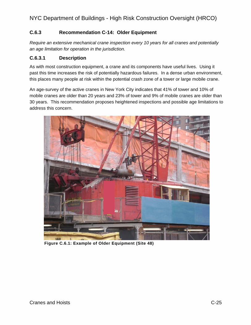
NYC Department of Buildings - High Risk Construction Oversight (HRCO)
Cranes and Hoists C-25
C.6.3 Recommendation C-14: Older Equipment
Require an extensive mechanical crane inspection every 10 years for all cranes and potentially an age limitation for operation in the jurisdiction.
C.6.3.1 Description
As with most construction equipment, a crane and its components have useful lives. Using it past this time increases the risk of potentially hazardous failures. In a dense urban environment, this places many people at risk within the potential crash zone of a tower or large mobile crane.
An age-survey of the active cranes in New York City indicates that 41% of tower and 10% of mobile cranes are older than 20 years and 23% of tower and 9% of mobile cranes are older than 30 years. This recommendation proposes heightened inspections and possible age limitations to address this concern.
Figure C.6.1: Example of Older Equipment (Site 48)

NYC Department of Buildings - High Risk Construction Oversight (HRCO)
Cranes and Hoists C-26
C.6.3.2 Recommendation Approach
The goal of the proposed 10-year inspection should be the evaluation of all safety related and load bearing components to assess their condition and to assure a safe operation until the next inspection of the component takes place.
An inspection plan/checklist indicating the items to be inspected and the type of inspection (e. g. “visual”, “measurement and comparison to manufacturer recommended values” or “NDT”) should be prepared by the following entities, in order of preference:
1. The Original Equipment Manufacturer (OEM). 2. A qualified OEM distributor or OEM local representative with a letter of the OEM
delegating this type of service work to the distributor or representative. 3. A Professional Engineer with experience in crane inspection if the OEM is not
available. Details of the inspection plan could include the following as well as any additional items that the above requires:
• Measure the turntable / slewing ring play in several directions and compare these with the OEM specified tolerances. If any measurement fails to meet the OEM minimum specifications or if such specifications are not available, the slewing ring should be repaired or replaced.
• Removal of at least 20 % of the slewing ring fasteners. These should include, at a minimum, the upper bolts in the boom/jib or counterweight/jib direction. These are visually checked for possible elongation and subjected to nondestructive testing (NDT), if there are any signs of cracking or elongation, all slewing ring fasteners must be replaced. As an alternative, all slewing ring fasteners are replaced without checking.
• Disassembly of all gearboxes for hoist and boom drives and brakes, if their components are not visible from the outside. Visual inspection and checking for wear of components like bearings, shafts, axles and gears. NDT or replacement of components, which would cause the load to slip or fall (e.g. various shafts, brake disks, gears, brake actuators).
• Inspection for wear and fatigue of all valves and hydraulic motors that hold, bear or control load movement and braking, and calibration and functional testing of these components after reassembly.
• Hydraulic cylinders should undergo a load holding test for at least 30 minutes to test for creep and leakage.
• All hydraulic hoses should be checked for signs of wear or deterioration and replaced if warranted.
• Sheaves and sheave bearings should be checked for wear and replaced if warranted.

NYC Department of Buildings - High Risk Construction Oversight (HRCO)
Cranes and Hoists C-27
• Telescoping booms should be disassembled to allow inspection and NDT of interior components and boom parts that are hidden in normal operation.
• All relay contacts, cable terminations, wiring, electrical components and enclosures should be inspected for worn / damaged insulation, signs of heat/burning and possible water ingress.
• Load bearing bolts and pins should be removed for inspection and subject to NDT.
• All load measuring devices should be recalibrated.
All components with defects or issues must be replaced or repaired as recommended by the OEM (see C-R-06, Repair and Maintenance). The reassembled crane must be load-tested with 100% rated load including all moment and a load holding test, including each outrigger (see C-R-15, load testing). For mobile cranes any overload warning devices should be tested as recommended by the manufacturer or the Engineer of Record.
This 10-year window for extensive inspection could provide an approach for identifying the “useful life” of a crane. A qualified inspector (see C-R-03, qualified inspector) would submit a detailed report of the inspection (including replacement part list) to DOB. This report would include a statement that the crane is fit and for safe operation and a set of conditions and requirements set by this inspector for the Owner to follow until the next major inspection. Some of these conditions and requirements may include:
• A change in the routine inspection schedule
• Special inspections at designated time intervals
• An extensive inspection at an earlier date than 10 years
• Install a device to count load/stress cycles
If the qualified inspector cannot provide this program for continued use, the crane would be deemed to have reached its “useful life”, and removed from service in NYC and the crane’s CD revoked.
Both NYC and OSHA require various crane components be inspected on frequent and periodic bases. These inspections are primarily exterior, visual inspections or exterior NDT inspections performed on directly accessible components or ones that can be accessed with minimal preparation. Some safety related or load bearing components are hidden from a visual inspection. These are subject to wear and fatigue.
Most crane manufacturers recommend long term inspection and maintenance requirements for components either in their manuals or when requested by the crane owner. There is no industry standard or a scope of long term inspection requirement specified by DOB.
Figure C.6.2 provides a tower crane age analysis that were in operation 1/29/09. In summary, 17 out of 34 tower cranes (50%) are more than 10 years old, and 23% are older than thirty (30)

NYC Department of Buildings - High Risk Construction Oversight (HRCO)
Cranes and Hoists C-28
years. The tower cranes over 30 years are primarily FMC TG1900 (62.5%) and Favco Model STD 1500 (37.5%).
Figure C.6.2: Tower Crane Age Distribution
Figure C.6.3 shows the age of mobile cranes registered with a NYC CD (certificate of operation). The results show that 209 out of 593 mobile cranes (35%) are more than 10 years old, and 9% are older than thirty (30) years.
Figure C.6.3: Mobile Crane Age Distribution

NYC Department of Buildings - High Risk Construction Oversight (HRCO)
Cranes and Hoists C-29
The relationship between the increased potential for equipment failures with increasing age can not be ignored. Recently, a crane suffered an equipment failure that caused an abrupt drop of the load (a concrete bucket reportedly weighing approximately 15,000 lbs). The cause of the failure was a worn drive shaft (see Figure C.6.4). The crane and the failed component were reported to be over ten years old. This component is not accessible to observation without a detailed inspection procedure as outlined above.
Figure C.6.4: Worn Pinion and Pinion Spine
C.6.3.3 Additional Considerations for Good Practice
The initial application for a certificate of operation for a used crane should require a statement by the manufacturer or its distributor that the crane still receives manufacturer support. DOB should not allow the registration of used cranes which are not supported by a manufacturer.
Age limits and manufacturer support are not included in DOB requirements to receive a certificate of operation (CD) for a used crane. All that is currently required is for the crane to have a valid a prototype certificate and pass the inspection.
Manufacturer support is extremely important for all cranes, and becomes even more critical for aging equipment. Reasons for this include:
1. Manufacturers provide service bulletins regarding performance issues that arise with cranes that are in operation.
2. Manufacturers are the most appropriate source for information on conducting repairs or retrofits to aging equipment.
3. The manufacturer is in the best position to assess the intended service life of a crane and its components based on their original design.
A study should be undertaken to determine the role of fatigue as it relates to useful life of cranes.
NYC Department of Buildings - High Risk Construction Oversight (HRCO)
Cranes and Hoists C-30
Steel structures, which are subjected to stress fluctuations or reversal, are subject to fatigue. As such, cranes designed in Europe use engineering standards that require the manufacturers to use formulae that calculate specific fatigue strength based upon the projected stress cycles. It is not unusual for a manufacturer to perform such calculations, but they are generally deemed proprietary and not available to the public.
If the number of stress cycles is exceeded, fatigue cracks will eventually start to appear. If these are not detected and repaired between when they first appear and the time of “rapid crack growth” the component will fail. With increasing fatigue this time window becomes shorter. There is further discussion of this in “Fatigue Design Basis” section.
DOB should work with the industry and manufacturers to determine the useful life of a crane or of their components via an engineering based approach. Consideration should be given to the fact that cranes in NYC often operate in densely populated and high traffic areas placing many people at risk that live and work in the potential crash zone. There is further discussion of this in section C.6.3.4.
There is currently no age limit on cranes operating in NYC. The industry replaces cranes for reasons including increased maintenance cost, decreased reliability, obsolescence, and/or higher productivity of newer equipment.
The NYC DOB requires Owners to subject the tower mast, jib and booms sections to NDT prior to the tower crane being assembled. In these inspections, tower and mast sections are rejected for a failed test. One such mast section was rejected when 2 out of 8 foot plates failed the NDT (Site C-95).
In various meetings with DOB, HRCO staff and manufacturers, manufacturers did not provide information regarding the useful life of their equipment. One representative maintained that a crane could have an “infinite” life but qualified this by noting that inspections and on-going maintenance and repair are necessary in assuring safe crane operation and that the frequency of required inspections and repairs will increase with the age of the crane.
Within the scope of the current investigation, the HRCO team could not collect sufficient information to establish crane retirement based on age or other criteria (such as inspection results or service history). A further investigation of this topic is required.
During the course of the HRCO investigation, one specific crane model became the source of investigation for fatigue-related failures. Investigations by DOB were on-going at the time of preparation of this report, so detailed findings were not available to the HRCO. But, as reported to the HRCO crane team, multiple cranes of the same model exhibited similar fatigue crack development.
The findings of such failure studies, which would differentiate between systemic and localized issues, should be used as the basis for assessing the risk of specific crane models and determination of conditions for their operation in the jurisdiction.

NYC Department of Buildings - High Risk Construction Oversight (HRCO)
Cranes and Hoists C-31
Cranes that lack certain design safety features should be updated with appropriate components to meet the newer standards or not be used in the city.
Older cranes generally have less advanced safety features. However, to equip the older cranes with some updated components may require a major rebuilding effort.
A common short-coming of older design is the limited access to the outermost tower bolts. In order to reach them, riggers must climb onto a platform that is attached to the outside of the tower. This platform is lifted into position on the outside of the tower using the crane and its position must be detached and reattached with each climbing section. In addition the tower crane rigger often has to change hook points for his safety harness. On 9/4/08 (Site C-94), an experienced tower crane rigger fell from a detachable, crane suspended work platform and died. A few weeks later on 11/12/08 (Site 49) the HRCO team witnessed a similar situation where a rigger climbed onto such a platform without a harness.
Newer tower cranes utilize different tower designs. This design does not require the worker to ride the load, and he can remain on a platform to change pick points during assembly, climbing or dismantling process. Tower bolts can either be reached without the use of an outside platform or a platform which remains attached to the climbing frame. This minimizes the danger of a fall or of being crushed by suspended loads (figures C.6.5 and C.6.6).
Figure C.6.5: Riggers “Riding the Load” Figure C.6.6: Rigger Kicks
Platform to Free It
On older mechanical mobile cranes, the different hoist drums for the boom and load hooks are driven by a single combustion engine. Using friction couplings, the different hoist drives are engaged or disengaged from the main engine by the operator while the engine is running. In addition, the operator must engage/ disengage the hoist brakes for the different hoists to move the particular hoist drum. The process of releasing the brake and engaging the coupling must take place at the same time without any jerking movement requiring skill from the operator (similar to starting up a car with a manual transmission on an incline).
Two riggers riding the load so they could re-position the hook point
Platform suspended from crane
Attachment points to tower

NYC Department of Buildings - High Risk Construction Oversight (HRCO)
Cranes and Hoists C-32
It is extremely difficult to install a safety device that automatically shuts down a hoist drum or boom drum on this type of crane. Newer cranes with hydraulic or electric drives automatically stop hoisting or booming (e.g. in case of two-blocking which could cause the boom or jib to break) when the load moment becomes too large (danger of tip over) or when the maximum line pull force is reached. With the older mechanical cranes these safety aids can only give an acoustical and optical warning to the operator
On 7/21/05, the boom of a mobile crane with mechanical transmissions broke off, because the operator’s foot slipped off a foot-pedal that caused a jerking hoist-drum movement. With newer hydraulic or electric cranes, acceleration and deceleration of components are dampened either by limiting valves or by more sophisticated control mechanisms so that a brief abrupt movement of the controls is less likely to create shock loading on the crane’s structure.
DOB grandfathered older cranes when it made certain safety aids mandatory (for instance, anti two blocking sensors for the Manitowoc 4100). In other cases DOB demanded retrofitting. There were two instances (3/9/05 and 6/29/07) where a grandfathered crane did not have an anti-two block device resulting in damage to the crane.
Therefore, primary items to consider would be:
• Larger mobile cranes (those that require a Certificate of On-site Inspection) should include features that automatically stop hoist or boom movements when an operational aid alerts the operator of a potentially risky situation. This includes but is not limited to:
o Anti two blocking device, o Load moment monitoring devices (having a rated capacity limiter
instead of a load and/or capacity indicator). o Maximum and minimum boom automatic angle shutoffs (instead of
stops only).
• Tower crane designs should minimize the situations where the tower crane riggers must “ride” a suspended load or work on platforms suspended from the crane hook.
C.6.3.4 Additional HRCO Observations There are a few public jurisdictions that require either assign a useful life or require more in-depth inspections as crane age. Below are the ones that have attempted to address this area.
The Australian standard 2550 (Cranes, Hoists and Winches – Safe Use) requires that cranes and lifting equipment undergo a Certification and Refurbishment when they have reached the end of their design life, (or where this is unknown after 25 years for the structure and 10 years for the mechanical). This includes a major inspection to assess their suitability for continued safe operation.

NYC Department of Buildings - High Risk Construction Oversight (HRCO)
Cranes and Hoists C-33
Singapore limits the service life of mobile cranes per the following schedule:
Design Safe Work Load (Max. Capacity)
Maximum Allowable Service Life (Mobile Crane)
mobile crane up to 50,000 kg [110,230 lbs]
20 years
mobile crane above 50,000 kg [110,230 lbs], up to 100,000kg [220,460 lbs]
25 years
mobile crane 100,000 kg [220,460 lbs] and above
30 years
Cranes exceeding the maximum service life need a “thorough assessment” by an approved 3rd party agency and approval by the MOM (“Ministry of Manpower” agency regulating construction work safety). This includes a proposal detailing “Usage Patterns (e.g. number of operating cycles per hour at certain load condition)” and a “proposed scheme to evaluate the remaining service life of the crane” including “The methodology and assessment employed including testing and inspection to be carried out to address potential fatigue stresses experienced by the crane”...
Singapore limits the service life of tower cranes per the following schedule:
Previous History of Crane Maximum Allowable Age, for Use in Singapore
used tower crane from overseas not registered
10 years
used towercrane not registered 15 years
registered towercrane 15 years, can be extended with manufacturers certificate
all other tower cranes 20 years
New Zealand regulations include the following: “As the end of the national design life of a crane approaches… at periodic intervals or when a second-hand crane is imported into New Zealand, inspection and testing shall be carried out in order to determine that the crane will remain safe for continued use. … If there is insufficient information to enable the equipment inspector to make a proper assessment of the condition of the crane, the inspection body shall not certify it

NYC Department of Buildings - High Risk Construction Oversight (HRCO)
Cranes and Hoists C-34
Fatigue Design Basis
Europe addresses fatigue of a crane’s metal structures by using the number of stress cycles a particular component undergoes. The service strength of a steel structure is influenced by the quantity (number) of stress cycles, the magnitude of the stress range, notch effects and steel grade.
The European standards classifies fatigue design of tower crane components relative to anticipated stress cycles ranging from 600,000 to 1.5 million. The stress magnitude is determined by the full stress range experienced by a component as it cycles from compression to tension and variations between the two. Finally, they consider the notch effect, which is a function of the shape, structural design, hole pattern or type and quality of the weld.
Depending upon the magnitude of the above, the allowable stress on a steel structure is reduced accordingly. The fatigue stress on the crane is introduced by repeated lifting and releasing loads and slewing of the crane. Wind influence is not considered when calculating fatigue.
As equipment approaches the service life (or fatigue limit) very small, and perhaps undetectable flaws, can grow at a rapid rate to a critical crack size that could cause failure. Procedures exist to estimate the number of cycles required for a flaw to propagate to a critical crack (one such is the Paris equation). This parameter of crack growth rate is necessary to determine the inspection interval that would be necessary for a crane that could be operating beyond its fatigue life.
Thus the essential logic for fatigue analysis of a crane involves:
1. Establishing the original fatigue design basis of the individual crane components (number of cycles and stress magnitude).
2. Determining the actual number of cycles experienced by a specific crane component. This could be accomplished in the future by mating data loggers (“black box”) with component tracking. In the absence of such technology, it requires estimates of cycles. A crane in steady use might accumulate on the order of 600 cycles per week, or 30,000 cycles per year.
3. Comparison of the actual service history with the design basis provides a measure of remaining life. It should be noted that this assumes the crane has been properly operated and has not been significantly overstressed – in which case the fatigue life could be significantly reduced. The application of data logging technology could serve to provide insight into whether crane components had been overstressed.
4. As a crane component approaches the fatigue limit there is an increased potential for relatively rapid development of fatigue cracks. At this point, the component could either be removed from service or, in theory, carefully monitored for crack development. Monitoring would require a determination of how quickly a crack could grow from

NYC Department of Buildings - High Risk Construction Oversight (HRCO)
Cranes and Hoists C-35
undetectable to hazardous. The inspection method and frequency would then need to be sufficiently conservative to ensure identification of fatigue crack growth at its early stages.
Airline Industry
The airline industry has recognized for many years the importance of applying stricter maintenance and repair systems on aging aircraft.
For the commercial aviation fleet, Congress passed the Aging Aircraft Safety Act of 1991 to address aging aircraft structural concerns resulting from the April 1988 accident involving a Boeing B-737. This noted failure (Aloha Airlines flight 243, NTSB Report # AAR-89/03), which was caused in part by fatigue issues, precipitated an overhaul of maintenance and repair procedures for aircraft. The commercial airline industry has an advantage over construction cranes in that the record keeping is far more advanced. For example, after the failure of Flight 243, the FAA was able to release flight restrictions and inspection requirements specifically for B-737’s with more than 30,000 landings, because detailed flight information was available from which to identify an age threshold at which planes might be at risk. Similar operational data, with which to establish the functional age of cranes and crane components, is not currently available.
Similar attention is being paid to aging aircraft in the general aviation fleet (typically smaller, private aircraft). Two aspects of best practices are currently being promulgated by the FAA: Airplane Record Research and Special Attention Inspection. Airplane Record Research provides a basis of information by compiling flight histories for the specific aircraft combined with operational records for its make and model. Special Attention Inspection recognizes that normal annual inspection may not be sufficient for aging aircraft and that more detailed inspections and rehabilitations may be needed to keep the aging aircraft at an acceptable level of reliability.

NYC Department of Buildings - High Risk Construction Oversight (HRCO)
Cranes and Hoists C-36
C.6.4 Recommendation C-21: Electric Tower Cranes (Further Study)
Have an all-electric tower crane fleet in the jurisdiction by a specified date.
C.6.4.1 Description Electric crane use is increasing for a multitude of reasons including environmental concerns and cost of operation. While those considerations are outside of the scope of the HRCO study, some aspects of electric crane use could positively impact crane operations in New York relative to safety. Thus, if there is a general move toward electric tower cranes, the HRCO crane team supports this for the following reasons:
Figure C.6.7: Electric Crane Figure C.6.8: Diesel Hydraulic Crane
• Provision of a modern crane fleet. This is the primary benefit of moving to an all-electric fleet. This would provide an opportunity to phase out older equipment lacking modern safety features.
• Removal of refueling operations. A typical diesel crane uses up to 10 gallons of fuel per hour and requires refueling every few days. This usually requires hoisting drums or tanks of fuel to the machine platform. This presents a very small but obvious risk of hoisting and handling flammable substances.
• Electric cranes require less hydraulic fluid. The primary reason is that the diesel machines require the fluid for their hoist drives, while electric cranes normally have a small amount of hydraulic fluid used in brakes and the climbing frame cylinders. There were two leaking incidents in NYC while the HRCO team was on assignment, both involving the same crane. The first one the HRCO team observed while investigating a crane (see Figure C.6.9), and the second time a hydraulic fitting failed and hydraulic fluid spewed into the street below requiring a HazMat response and clean up.

NYC Department of Buildings - High Risk Construction Oversight (HRCO)
Cranes and Hoists C-37
• Diesel crane engine noise levels exceed 90 dBA. Electric cranes operate at less than 80 dBA. This is a significant difference, relative to hearing health, for anyone working in vicinity of the crane.
Figure C.6.9: Leaking Hydraulic Fitting
C.6.4.2 Recommendation Approach The final time frame should be selected so as to provide sufficient notice to owners and operators so they may adjust their crane usage and fleets.
A number of logistics would need to be investigated for this recommendation. For example, electric cranes require an electrical power source. Most buildings should have sufficient power from the electrical grid by the time the tower crane arrives on site. But, this will require some coordination between the user, the City and the electric company.

NYC Department of Buildings - High Risk Construction Oversight (HRCO)
Cranes and Hoists C-38
C.6.5 Recommendation H-1: Hoist Equipment Acceptance (Further Study)
Create and implement an Equipment Acceptance Certification program for hoisting equipment employed in the NYC area.
C.6.5.1 Description There is no current requirement, or standardized quality assurance program to ensure hoist equipment in use in NYC is in compliance with standard industry quality assurance practices for design, manufacture, materials, testing, and that it is in compliance with all applicable regulatory specifications. This recommendation proposes an Equipment Acceptance Certification that would require Hoist Contractors to certify that the equipment employed by them has satisfactorily passed minimum quality requirements.
For the most part the hoist industry is not required to provide or record quality assurance information for their equipment and as such they typically don’t require it from their suppliers. Contractors will simply buy a hoist, mast, or mechanical drive parts without requiring quality assurance certifications. Additionally, some contractors manufacturer their own equipment but not necessarily with any specific quality control program in place.
During the course of this study the HRCO hoist team visited 6 hoist contractor facilities. All of them but one performs some form of fabrication or major repairs. Aspects of contractor QA/QC procedures are summarized in Table C.6.3 and discussed below.
Of the five contractor facilities that have shops for fabrication and repair, only two maintain some manner of quality control program. These two facilities have extensive operations, performing major modifications to their cars and mast sections (one facility even fabricates their own mast sections). Quality procedures at these two facilities include:
• quality inspections on the mechanical drives and rebuild or repair any defective parts
• mast sections are UT tested and have identification numbers for traceability
• in-shop testing of assembled cars (including drop tests)
However, neither actually has a formally documented quality control program.
A third contractor had no quality control program, though they do perform UT and then tag tested sections but only at the client’s request. They also perform car testing in shop.
The remaining 2 of the 5 contractors that perform fabrication and repair work exercise very little quality assurance. One of them makes major repairs to the majority of their mast section inventory without qualified welders. The welder observed by the HRCO hoist team was not AWS or New York State certified. This contractor also did not have the means to shop test their cars, although there were at least aware of the potential for internal corrosion of mast legs perform UT testing before returning them to service.
None of the contractors required quality assurance information from the suppliers and manufacturers that they buy their equipment from. And although many of them are buying premium products from established manufacturers, just as many are buying “cloned” products.

NYC Department of Buildings - High Risk Construction Oversight (HRCO)
Cranes and Hoists C-39
One contractor purchases less expensive “cloned” equipment and then rewires the entire car to meet UL standards, removes and replaces floor plates and cage, and removes and replaces the gearing in the drive. They claimed that after one installation with the “cloned” parts, the gears wear out. So they replace them with a German made product from the outset.
Table C.6.3: Summary of Hoist Contract QA/QC Practices.
Contractor Formal QA/QA program?
Requires QA/QC from Supplier?
Degree of informal QA/QC
#1 No. No. Moderate #2 No. No. Moderate #3 No. No. Little #4 No. No. Little #5 No. No. Little
C.6.5.2 Recommendation Approach Hoist contractors would certify that equipment in service meets or exceeds specific criteria. The criteria could include:
1. Design of such equipment has been performed by a qualified engineer, for example, as demonstrated by a minimum of 10 years experience in the design of similar type equipment.
2. Manufacturer of equipment is certified to a relevant quality assurance program (e.g. AISC certification). The quality program should be documented in a manner that can be submitted to DOB.
3. All weld procedures, including weld process qualification reports (WPQR), weld materials, weld process specification (WPS), and welder qualifications, must be in accordance with AWS D5.1 or D5.5, as required.
4. All materials are as required by design and are mill certified.
5. Product testing is to be performed on all products to confirm load ratings.
6. All in-service equipment must be in its original manufactured configuration. Any parts that are replaced or repaired must meet Original Equipment Manufacturer (OEM) standards.
7. Gearing, bearings, shafting, brake liners, housings, cable, rollers, limit switches, must all be by original OEM products or be by approved manufacturers.

NYC Department of Buildings - High Risk Construction Oversight (HRCO)
Cranes and Hoists C-40
C.7 SITE SPECIFIC DESIGN C.7.1 Description
This section addresses issues that relate to the overall site design of tower and large crawler cranes. This includes foundations for tower and crawler cranes and building tie-ins for tower cranes. Many times these site-specific design elements are altered during crane erection due to unanticipated site conditions.
Recommendations for tie-ins and foundations serve to expand and strengthen engineering efforts by crane and building engineers as well as DOB plan examiners. No matter how well designed, manufactured or maintained, if a construction crane is not properly supported, it could be subject to catastrophic failure.
Tower and large mobile cranes rely on counterweights to support lifted loads. Proper configuration of the counterweights (as well as general functioning of the crane) is confirmed by a load test prior to putting the crane into service. Recommendations for load tests and counterweights primarily take practices already recommended in standards and by manufacturers and formalize them for NYC.
The further study recommendation for wind loading is related to the understanding that local wind loads in urban environments can vary significantly from standard wind load charts. A related recommendation for high-rise concrete calls for increased monitoring of actual wind speeds in Manhattan. Data from this study should be used to assess the appropriateness of current crane design wind speeds.
The hoist recommendation for engineering sign-off calls for a formal review of the ability of the building to support loads imposed by the hoist equipment.

NYC Department of Buildings - High Risk Construction Oversight (HRCO)
Cranes and Hoists C-41
C.7.2 Recommendation C-8: Tie-Ins
Tie-In connections should be subjected to special inspection and require improved design and erection procedures.
C.7.2.1 Description
Tie-ins are used with tower cranes that exceed the maximum freestanding tower heights set by the crane’s Original Equipment Manufacturer (OEM). In such instances, the crane tower is usually attached to the building being constructed. The tie-ins transfer the lateral reaction forces of the tower crane to the building structure. Their placement, location and design are specific to each application and are prepared by the OEM or the Engineer of Record. Tie-in design, calculation and installation are approved by DOB as part of the "Certificate of On-Site Inspection" [CN].
Figure C.7.1: Examples of Tie-ins (Site C-10)

NYC Department of Buildings - High Risk Construction Oversight (HRCO)
Cranes and Hoists C-42
C.7.2.2 Recommendation Approach
Implementation of this recommendation should include the following actions:
• The connection at the building’s floor slab should be subjected to Special Inspection for conformance with the approved drawings.
• If using friction connections, the crane Engineer of Record must specify the required bolt torque to providethe necessary clamping forces between the steel tie-in foot plate and the concrete slab are included in the design.
• If using a bearing connection, the crane Engineer of Record and the contractor should check that the bolt holes in the concrete have a close tolerance, and the bolts/threaded rods should be pre-tensioned. An alternative is the use of grout or steel bushings.
• Permitting of crane and hoist machines should require PE sign-off for loads imposed.
The connection at the building’s floor slab should be subjected to Special Inspection for conformance with the approved drawings.
This inspection would include photographs showing the rebar-placement and documentation of the inspection in a log available to DOB. For installations that require higher-strength concrete at the tie-in locations than in adjacent regions of the floor slab, the contractor should supply test results, to the Special Inspector, verifying required concrete strength.
Tie-in design and installation are covered under Chapter 33 of the New York City Construction Code, and more specifically paragraph 3319.6 requires the equipment user, or his designated representative, to apply for and obtain a certificate of on-site inspection that DOB must approve prior to a crane arriving at site. DOB presently does not require Special Inspection of, or typically inspect, the tie-in locations prior to pouring concrete.
One occurrence was noted where the concrete design strength was higher than the installed strength. This was confirmed by the Crane EOR, and the EOR provided calculations that the lower installed strength was acceptable based upon the design criteria. If the original design was correct, the concrete may have failed. There was also an occurrence where the building EOR added rebar to the Crane EOR’s design to overcome the bending moment on the concrete slab (site C-110 4/7/09). Figure C.7.2 shows the addition to the Crane’s EOR drawings and the building EOR stamping the drawing.
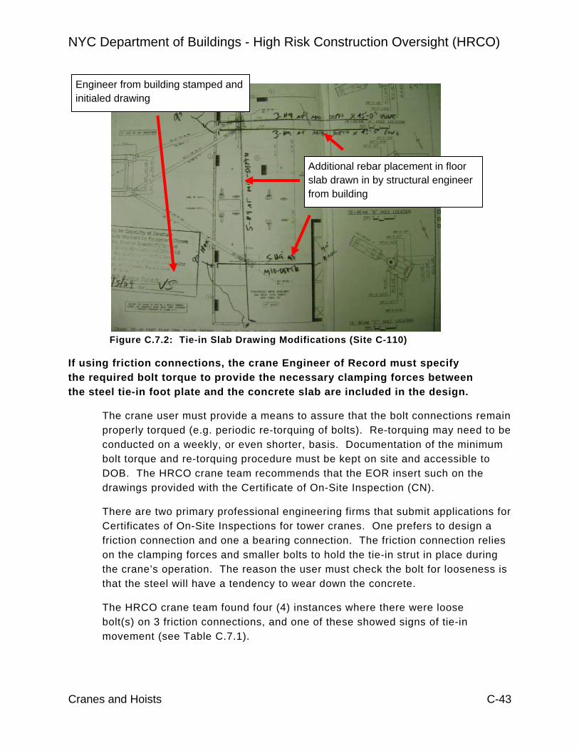
NYC Department of Buildings - High Risk Construction Oversight (HRCO)
Cranes and Hoists C-43
Figure C.7.2: Tie-in Slab Drawing Modifications (Site C-110)
If using friction connections, the crane Engineer of Record must specify the required bolt torque to provide the necessary clamping forces between the steel tie-in foot plate and the concrete slab are included in the design.
The crane user must provide a means to assure that the bolt connections remain properly torqued (e.g. periodic re-torquing of bolts). Re-torquing may need to be conducted on a weekly, or even shorter, basis. Documentation of the minimum bolt torque and re-torquing procedure must be kept on site and accessible to DOB. The HRCO crane team recommends that the EOR insert such on the drawings provided with the Certificate of On-Site Inspection (CN).
There are two primary professional engineering firms that submit applications for Certificates of On-Site Inspections for tower cranes. One prefers to design a friction connection and one a bearing connection. The friction connection relies on the clamping forces and smaller bolts to hold the tie-in strut in place during the crane’s operation. The reason the user must check the bolt for looseness is that the steel will have a tendency to wear down the concrete.
The HRCO crane team found four (4) instances where there were loose bolt(s) on 3 friction connections, and one of these showed signs of tie-in movement (see Table C.7.1).
Additional rebar placement in floor slab drawn in by structural engineer from building
Engineer from building stamped and initialed drawing

NYC Department of Buildings - High Risk Construction Oversight (HRCO)
Cranes and Hoists C-44
(Site C-10, 3/5/09) (Site C-73, 1/19/09)
(Site C-55, 1/5/09)
Figure C.7.3: Examples of loose friction tie-in strut connections
If using a bearing connection, the crane Engineer of Record and the contractor should check that the bolt holes in the concrete have a close tolerance. The bolts/threaded rods should be pre-tensioned. An alternative is the use of grout or steel bushings.
This is one of the preferred tie-ins designs submitted by the EOR’s in New York City. The bearing connection uses larger bolts and relies on the allowable bearing pressure of the concrete.
The ability to check a bearing connection is limited to when the crane is dismantled. The HRCO crane team observed one instance of a bearing connection with loose bolts (see Table C.7.1).
3 hand-loose bolts
Pattern of dirt was pushed by movement of tie-in in direction of blue arrow
Rust streak shows plate movement
Dirt not disturbed on this edge, no movement in that direction
1 loose bolt, confirmed by hammer-tap

NYC Department of Buildings - High Risk Construction Oversight (HRCO)
Cranes and Hoists C-45
Figure C.7.4: Friction Connection Bolts (Site C-88 – 1/5/09)
Issue Checked Occurrence
Tie Installation Differed from the Original Design
2 2
Loose Connection Bolts on a Friction Connection (21 tie-ins on 11 cranes were checked)
21 4
No Building Engineer or Independent PE Sign-off on Loads Imposed.
14 10
Table C.7.1: Observations of Tie-In Connection Issues
Example of loose bolt on a friction connection

NYC Department of Buildings - High Risk Construction Oversight (HRCO)
Cranes and Hoists C-46
Require the building engineer of record or an engineer acceptable to DOB to review the plans to determine the building can support the loads imposed by the crane.
The procedure would require the following to be submitted to DOB:
• Building structural information submitted by the building Engineer of Record with currently available information to support an analysis of loads imposed by the crane equipment (if available for existing buildings).
• An analysis of the loads imposed by the crane equipment (considering at a minimum, local resistance of reaction forces and lateral system analysis) by either the building Engineer of Record or by a licensed professional engineer acceptable to the Department of Buildings. The reviewer should document this by a signed shop-drawing stamp on a copy of the approved tie-in drawing.
DOB has examiners that review each application for compliance to the regulation and they check the calculations provided by the licensed engineer. The examiners require the crane licensed engineer to provide the calculations of forces created by the crane. Generally, the building engineer has not signed off or stamped the crane drawing indicating that the building and slab can withstand the forces.
A review of 14 open CN’s showed only four contained such a letter or stamp from the building (or independent) engineer (see Table C.7.1). On one of these occurrences, the building EOR added rebar to overcome a bending moment in the slab (Site C110).
C.7.2.3 Additional Considerations for Good Practice
Climbing frames should be stored at all times in accordance with manufacturer recommendations (typically this is at the top tie-in). The Site Safety Manager or similar personnel should receive specialized training and tools allowing them to supervise loosening of tie-ins as required in case of a storm warning.
Presently, only a Master Rigger can supervise all aspects of the assembly, climbing or dismantling of a tower crane. The HRCO crane team observed one occurrence in which the plans lacked detailed information regarding the releasing of a tie-in.
Some site drawings prepared by the engineer of record require that in cases of an upcoming storm condition certain tie-ins must be loosened and/or the climbing frame lowered and secured at the top tie-in. In New York City, only a licensed master rigger and properly trained crew are allowed to perform these operations.

NYC Department of Buildings - High Risk Construction Oversight (HRCO)
Cranes and Hoists C-47
There may be, at any one time, at least 20 cranes requiring these storm preparations located within the jurisdiction. This could put extreme pressure on the limited number of licensed riggers that can prepare the cranes properly. The engineer of record should prepare the loosening procedure and provide training and instructions for specific tie-ins.
Tie-in installation should be done only when the crane is in a balanced position. This will assist in the event where a tie-in must be released and re-installed.
Installing ties while the crane is “balanced” (i.e. the crane is configured to minimize the overturning moment) minimizes the force in the tie. In this way, if the crane is returned to the balanced position when the tie needs to be released the unbolting process will be much easier. This is a particularly beneficial in case a tie must be released in an emergency situation such as a high wind alerts.
Require positive steel rope or steel structure support from the tie-in collar to the tower leg.
It is common practice to attach wire ropes from the tie-in collar to a mast section/leg as a safety should the primary collar attachment to the tower via shims, threaded friction pads or similar means come loose.
At two installations the safety sling for the tie-in collar was attached to a horizontal member (Figures C.7.5 and C.7.6). This introduces a bending moment on a tension or compression member that is normally not designed for bending.
If the tie-in collar is not close (as defined by the manufacturer) to a panel point on the tower section, the tower-legs should be reinforced or inner bracings installed in accordance to the manufacturer’s recommendations.
Engineers of record typically design the crane installations with the tie-in collars at panel points or note that reinforcement of the mast section is required. This is a good practice that should be promoted (Figure C.7.7).

NYC Department of Buildings - High Risk Construction Oversight (HRCO)
Cranes and Hoists C-48
Safety slings attached to tower lacings
.
Figure C.7.7: Example of Tower Reinforcement at Tie-in (Site C-78, 10/9/08).
The circled beam is an example of inner-bracing near the collar
Safety slings attached to tower lacings
Figure C.7.5: Safety Slings at Site C-62.
Figure C.7.6: Safety Slings at Site C-73.

NYC Department of Buildings - High Risk Construction Oversight (HRCO)
Cranes and Hoists C-49
C.7.2.4 Additional HRCO Data
Several jurisdictions and national standards have regulations that specifically speak to verifying the appropriate loads for tie-ins. Table C.7.2 provides a summary of a few.
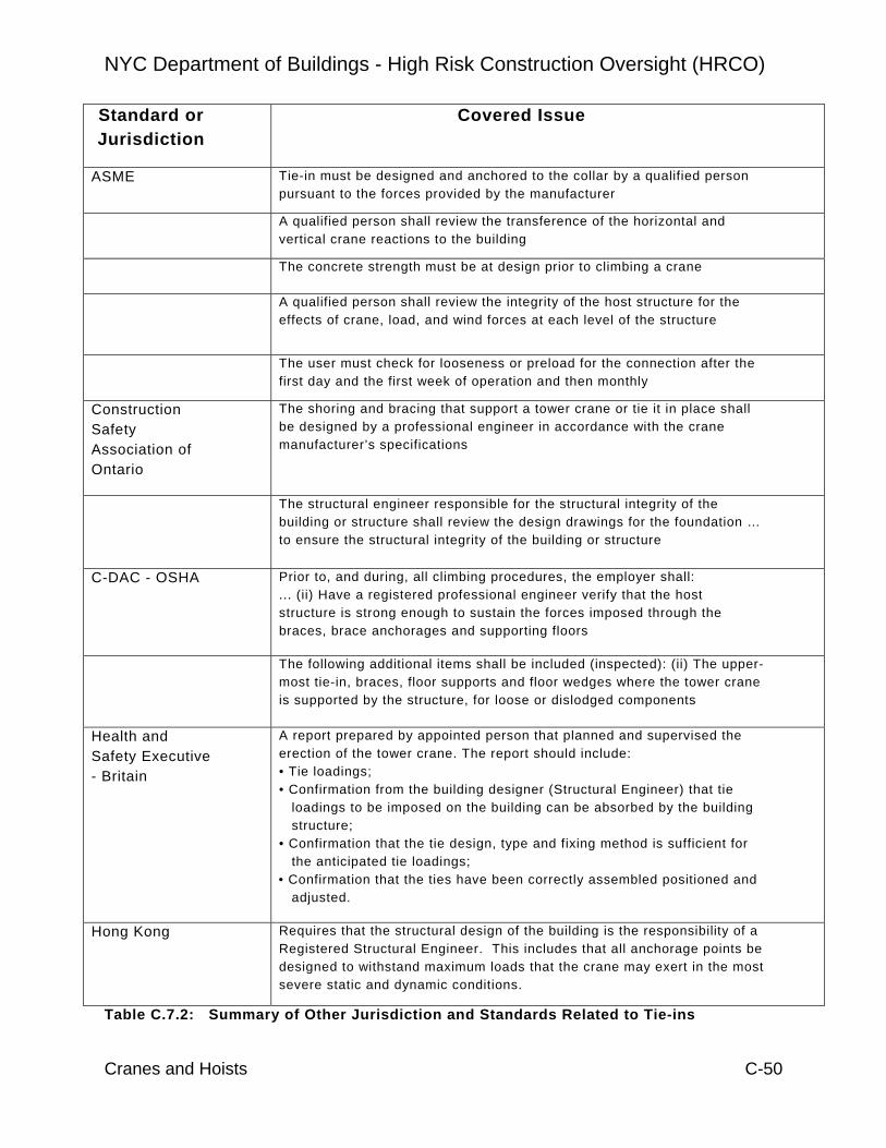
NYC Department of Buildings - High Risk Construction Oversight (HRCO)
Cranes and Hoists C-50
Standard or Jurisdiction
Covered Issue
ASME Tie-in must be designed and anchored to the collar by a qualified person pursuant to the forces provided by the manufacturer
A qualified person shall review the transference of the horizontal and vertical crane reactions to the building
The concrete strength must be at design prior to climbing a crane
A qualified person shall review the integrity of the host structure for the effects of crane, load, and wind forces at each level of the structure
The user must check for looseness or preload for the connection after the first day and the first week of operation and then monthly
Construction Safety Association of Ontario
The shoring and bracing that support a tower crane or tie it in place shall be designed by a professional engineer in accordance with the crane manufacturer’s specifications
The structural engineer responsible for the structural integrity of the building or structure shall review the design drawings for the foundation … to ensure the structural integrity of the building or structure
C-DAC - OSHA Prior to, and during, all climbing procedures, the employer shall: ... (ii) Have a registered professional engineer verify that the host structure is strong enough to sustain the forces imposed through the braces, brace anchorages and supporting floors
The following additional items shall be included (inspected): (ii) The upper-most tie-in, braces, floor supports and floor wedges where the tower crane is supported by the structure, for loose or dislodged components
Health and Safety Executive - Britain
A report prepared by appointed person that planned and supervised the erection of the tower crane. The report should include: • Tie loadings; • Confirmation from the building designer (Structural Engineer) that tie
loadings to be imposed on the building can be absorbed by the building structure;
• Confirmation that the tie design, type and fixing method is sufficient for the anticipated tie loadings;
• Confirmation that the ties have been correctly assembled positioned and adjusted.
Hong Kong Requires that the structural design of the building is the responsibility of a Registered Structural Engineer. This includes that all anchorage points be designed to withstand maximum loads that the crane may exert in the most severe static and dynamic conditions.
Table C.7.2: Summary of Other Jurisdiction and Standards Related to Tie-ins
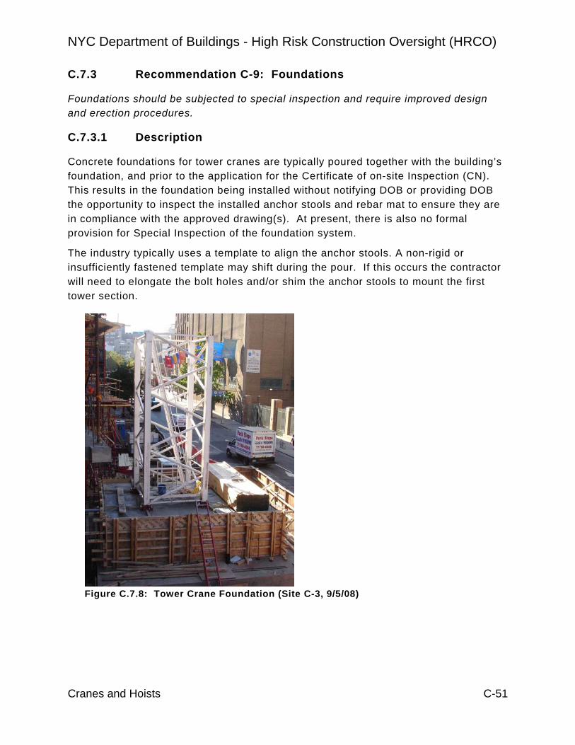
NYC Department of Buildings - High Risk Construction Oversight (HRCO)
Cranes and Hoists C-51
C.7.3 Recommendation C-9: Foundations
Foundations should be subjected to special inspection and require improved design and erection procedures.
C.7.3.1 Description
Concrete foundations for tower cranes are typically poured together with the building’s foundation, and prior to the application for the Certificate of on-site Inspection (CN). This results in the foundation being installed without notifying DOB or providing DOB the opportunity to inspect the installed anchor stools and rebar mat to ensure they are in compliance with the approved drawing(s). At present, there is also no formal provision for Special Inspection of the foundation system.
The industry typically uses a template to align the anchor stools. A non-rigid or insufficiently fastened template may shift during the pour. If this occurs the contractor will need to elongate the bolt holes and/or shim the anchor stools to mount the first tower section.
Figure C.7.8: Tower Crane Foundation (Site C-3, 9/5/08)

NYC Department of Buildings - High Risk Construction Oversight (HRCO)
Cranes and Hoists C-52
C.7.3.2 Recommendation Approach
Implementation of this recommendation should include the following actions:
• The Crane Engineer of Record (EOR) should submit foundation plans to DOB prior to pouring; and in addition to structural details of the foundation anchorage, the plans should identify any issues and conflicts with known site conditions
• Require Special Inspection before the foundation pour to confirm conformance with design drawings. To facilitate this, the crane user should notify DOB at least 48 hours prior to the foundation pour to provide opportunity for DOB to audit the installed condition.
• Allow the crane installation contractor to use an actual tower mast section to assist with the alignment of the anchor stools by casting the stools into the foundation while attached to the section. If a template is used, it must satisfy ANSI B30.3 requirements. If a mast section is used, the Contractor should request DOB to perform a pre-assembly inspection for the installed section.
• The crane user should install Original Equipment Manufacturer anchor stools whenever available.
The Crane Engineer of Record (EOR) should submit foundation plans to DOB prior to pouring; and in addition to structural details of the foundation anchorage, the plans should identify any issues and conflicts with known site conditions.
The typical foundation design and construction process (particularly for crane foundations that fall within the foot print of the new building) involves the following:
• The tower crane foundation is designed by the crane Engineer of Record (EOR) and constructed in conjunction with the building foundation.
• The process typically occurs weeks or months in advance of selecting a specific tower crane make and model.
• The EOR designs the crane foundation to accommodate the worst-case loads from probable crane models.
• Adapters are used, as necessary, to mate the final crane selection to the existing foundation.
Once the contractor decides on a particular type of crane, he applies for a Certificate of On-Site Inspection sending plans and calculations of the

NYC Department of Buildings - High Risk Construction Oversight (HRCO)
Cranes and Hoists C-53
foundation to DOB. As identified above, DOB reviews the plans for the foundation as part of the certification process.
The HRCO team noted instances where the foundation was poured prior to the CN submittal. NYC crane industry representatives confirmed in DOB industry meetings, that this is commonplace.
Figure C.7.9: Poured Foundation (Site C-78, 8/7/08)
On one occasion, the foundation was poured while the plan examiners were reviewing the application. In this instance, the contractor attempted to epoxy dowels in concrete just 2 days after it was poured without consulting the epoxy manufacturer. DOB discovered this due to an inspector being on-site for another reason and stopped the job until the epoxy manufacturer was consulted (Site C-78).
Foundation design and eventual installation are covered under Chapter 33 of the New York City Construction Code, and more specifically paragraph 3319.6 requires the equipment user, or his designated representative, to apply for and obtain a Certificate of On-site Inspection that DOB must approve prior to a crane arriving at site.
In order to better ensure that the established technical requirements are being followed, the Department should require a Special Inspection before the foundation pour to confirm conformance with design drawings. To facilitate this, the crane user should notify DOB at least 48 hours prior to the foundation pour to provide opportunity for DOB to audit the installed condition.
The foundation is poured and the rebar placement cannot be checked.

NYC Department of Buildings - High Risk Construction Oversight (HRCO)
Cranes and Hoists C-54
Special Inspections have not been required. However, the industry has performed some at their own discretion. Proper crane foundation construction is critical for the support of the crane, particularly the initial period of use when the crane is free-standing. Special inspection is clearly warranted to provide assurance of proper construction.
Allow the crane installation contractor to use an actual tower mast section to assist with the alignment of the anchor stools by casting the stools into the foundation while attached to the section.
If a template is used, it must satisfy ANSI B30.3 rigidity requirements. If a mast section is used, the Contractor should request DOB to perform a pre-assembly inspection for the installed section.
DOB does not currently allow the contractor to use a tower section until the CN is approved. DOB deems a tower section as a partial “tower crane erection”. For this reason, the industry defaults to using templates. Previously, DOB authorized the contractors to use the first section as a template. It is the HRCO understanding that DOB is working to amend this restriction and allow a section to be used as outlined above.
The HRCO team witnessed instances where the installation team had to use shims and/or enlarge the bolt holes to attach the first section to the anchor stools. This practice places an additional bending moment on the bolted connection. The use of the first section will allow the installation team to plumb the tower prior to pouring the foundation, which will minimize the need to shim and enlarge bolt holes. Figure C.7.10 shows an anchor stool and tower section that illustrates the need to shim the tower to achieve plumbness.
The HRCO team observed one contractor that used half of a tower section as a template and one that made one from a non-rigid material (½” plywood) (site C-89 – 10/17/08).

NYC Department of Buildings - High Risk Construction Oversight (HRCO)
Cranes and Hoists C-55
The crane user should install Original Equipment Manufacturer anchor stools whenever available.
The practices in NYC are that the crane owner or user installs an anchor stool of their choice, and the licensed crane engineer designs anchor stools for particular cranes.
One custom (non-OEM) anchor stool was under-designed by the Crane Engineer of Record and required reinforcement prior to the crane being assembled.
(Figure C.7.11: Site C-89 – 10/28/08, under designed anchor stool)
Figure C.7.10: Site C-55 – 10/9/08, examples of excessive shimming and bolt-hole elongation probably shifted.
Because of shifted anchor-stool, the bolt holes had to be elongated so much, that an ordinary nut/washer could not be used any more. A steel plate was used instead.
Ordinary bolted connection, nut and washer used
Shims to level tower crane section
Base of tower section has large diameter foot plate
Reinforcement had to be used after recalculation
Plate of anchor stool designed by engineer of record is too thin.

NYC Department of Buildings - High Risk Construction Oversight (HRCO)
Cranes and Hoists C-56
C.7.3.3 Additional Considerations for Good Practice
The practice of designing a foundation prior to selection of a specific crane make, model and configuration leads to situations where special adapters must be designed to mate incompatible anchors and tower legs. It also creates the possibility for foundation design error (i.e., inaccurate and/or insufficient loads). The industry should move to a system in which the foundation is designed specifically for the crane that is actually used.
C.7.3.4 Additional HRCO Data
Several jurisdictions and national standards have regulations that specifically address verification of the appropriate loads for foundations. For example:
ASME B30.3-2004 Construction Tower Cranes recommends that the first tower mast section be used and be secured before the concrete foundation is poured. If this cannot be done, the standard requires a template to be rigid and built so that the tower leg bearing surfaces are in the same plane.
C-DAC - OSHA The proposed OSHA rules in C-DAC, include the following:
$1926.1435 Tower Cranes “(b) Erecting Climbing and Dismantling (3) Foundations and structural supports. Tower crane foundations and structural supports shall be designed by the manufacturer or a registered professional engineer. (4) Addressing specific hazards ... In addition, the Assembly/Disassembly (A/D) supervisor shall address the following: (i) Foundations and structural supports. The A/D supervisor shall verify that tower crane foundations and structural supports are installed in accordance with their design.” Singapore requires new foundation anchors each time a tower crane is assembled. Further, the Ministry of Manpower circular OSHD / LE 1/08 implies that the foundation is inspection prior to the pouring of concrete;
Britain Uses an approach, where the HSE (Health and Safety Executive) similar to the American OSHA decided, that tower cranes have to be erected by the crane owner, who hands the erected crane over to the crane hirer. The crane hirer normally provides the tower crane foundation. Internal documents are used to assure the quality of the foundation. The HSE approved publication “Safe Use of Top Slew Tower Cranes” describes the procedure and shows an example:

NYC Department of Buildings - High Risk Construction Oversight (HRCO)
Cranes and Hoists C-57
“This loading information should be used by the foundation designer employed by the user, to produce an adequate design, taking into account the ground conditions on site. Wherever a concrete pad, steel grillage, piled foundation or rail track is constructed to accept the loads from a TSTC, the contractor constructing the foundation should complete a foundation completion form to certify that the foundation has been correctly designed and constructed before erection of the crane starts.”
Figure C.7.12: UK Certificate
The British Health and Safety Executive (HSE) approved publication “Maintenance Inspection and Thorough Examination of Tower Cranes; a Best Practice Guide” gives further information regarding the foundation inspection in section A11.12 (Foundation As–Built Report).
This report confirms that the foundations have been constructed in accordance with the foundation design (see summary in Table C.7.3). The report should be prepared by the organization that has constructed / installed the foundation. The appointed person responsible for the planning and supervision of the crane erection should countersign the report.

NYC Department of Buildings - High Risk Construction Oversight (HRCO)
Cranes and Hoists C-58
All Foundations • Report confirming the foundation is in accordance with the foundation designer’s drawings.
• Measurements confirming dimensional accuracy and level.
Cast-in Items • Level, plumb and to tolerance. Reinforced Concrete
• Record of concrete mix and placement date, cube tests were carried out, to ensure concrete is of the correct grade and sufficient maturity.
Piles • Results of pile tests. • Confirmation that the design has sufficient reinforcement bond length into pile cap and that the pile to take tension where applicable.
Steelwork • Steel dimensionally correct and to the correct grade. • Bolts to the correct grade and tightened to specified torque. • Weld quality (NDT results if required).
Rails • Bedding properly compacted. • Sleepers of sound quality and rail clips securely fastened. • Rail centres and levels to correct tolerances. • Limit ramps and end stops correctly positioned and firmly fixed. • Rails earthed.
Table C.7.3: Summary of the UK Foundation As-Built Report.
New Zealand states the following requirements in the “Approved code of practice for cranes” published by the Department of Labour:
“10.2 (6) Part 2: The inspection and testing of the tower crane after erection and annual inspection for recertification.
Inspections and testing will cover (but are not limited to) the following items. The following documentation is to be provided by the controller to the equipment inspector prior to testing commencing: (b) Foundation certificate, covering design and construction, from a chartered professional engineer and crack testing results of base anchors. IANZ-endorsed NDT reports are required.”

NYC Department of Buildings - High Risk Construction Oversight (HRCO)
Cranes and Hoists C-59
C.7.4 Recommendation C-15: Load Test
The test weights to be used should not exceed the manufacturer’s specification or, in case where the manufacturer is not available, the applicable ANSI standard should be followed..
C.7.4.1 Description
A load test is part of DOB crane inspections (required by RS 19-2) for tower cranes. The test verifies that the crane, generally, is able to lift and hold the maximum rated load at the corresponding radii. Further, the installed safety devices warn the crane operator about a maximum load situation and eventually stop the lifting, booming, lowering and/or trolley out motions. The Engineer of Record for the Certificate of on-site inspection (CN) provides the load test procedure with eachapplication.
Figure C.7.13: Load Test in Operation
In two cases a test load of the exact weight was not available on site, and the engineer of record provided a test procedure where the crane would have attempted to lift a test load exceeding the maximum allowable weight. In case of a malfunction of the safety devices that are to be tested, the crane could have been overloaded. In extreme cases this could cause catastrophic crane failure. In other cases, structural components and parts of the hoisting apparatus of the crane could have been overstressed, causing deformation, cracking or general weakening of crane components. These defects are often hidden and could heighten the risk of a catastrophic failure at a later date. In 2008, there was an incident that a crane dropped a load during a load test.

NYC Department of Buildings - High Risk Construction Oversight (HRCO)
Cranes and Hoists C-60
C.7.4.2 Recommendation Approach
The Engineer of Record should include manufacturer recommendations or ANSI information when providing the load test procedure in the Certificate of on-site inspection (CN). In addition, the procedure should include:
• Line pull test should be performed on all gears • A moment test should be performed as a standard practice for all load
tests. • All limit and pre-limit switches should be tested during the load test.
Inspectors from DOB witness all tower crane load tests. However, DOB has allowed procedures that could have overloaded the crane based upon the EOR’s procedures included in the CN.
The HRCO moderated a conference of major crane manufacturers in November 2008. The manufacturers unanimously confirmed that load tests should be conducted with a test weight limited to the proper test load and that the crane should not be placed in a situation whereby it may become over-loaded. Similarly, ANSI standards B30.3 and B30.5 regarding load test states that the weight should not exceed 110% of the rated load.
Load test procedures submitted by engineers of record on C/N applications have created situations where the crane could have been overloaded as shown in Table 7-4. Further, load test procedures submitted by engineers of record for C/N application and reviewed by the HRCO team were contrary to the manufacturer’s recommendation and the ANSI B30.3 standards by designing a protocol that the crane could have attempted to lift a weight 130% over the rate load should the safety features fail.
In three instances, the EOR did not include a moment over-load test. Cranes typically have two controlling load cases, maximum load and maximum moment. Both controlling cases must be checked to confirm the safety of the crane. Checking just one does not confirm whether the crane can safely operate under the other condition.
Reference Standards 19-2 (Paragraph 13.1) (dated September 14, 2006) requires that load ratings for climber tower cranes be conducted so that no structural member is overstressed.

NYC Department of Buildings - High Risk Construction Oversight (HRCO)
Cranes and Hoists C-61
Issue CN’s Checked Occurrences
Crane could have lifted more than 110%
13 5
Procedures on CN’s that did not have a moment test
13 3
Procedure did not include a line pull on all gears
13 2
C.7.4.3 Additional HRCO Observations
The primary focus on the benchmarking activity on this recommendation was on standards published in the United States. Two such standards were developed by the American Society of Mechanical Engineers (B30.3 and B30.5). The tower crane standard (B30.3) primarily recommends that after erection (and climbing operations) all functional motion, limiting devices and brakes be tested prior to the operation. The static test load should be in the range of 102.5% to 110%, as recommended by the manufacturer. The Mobile crane standard (B30.5) requires a load test prior to the initial use or if load sustaining parts have been altered, replaced or repaired. The load test weight shall not exceed 110% of manufacturer’s load rating.
In addition, manufacturers do not allow over loading the crane. Below is a portion of a load test procedure outlined in an OEM’s operating manual.
“Set the switch OS 11 "Hoist up": Attach the test load (minimum: permissible load at the end of the jib; maximum: permissible load at the end of the jib +10%).
Set the switch OS 12 "Trolley forward": Attach the test load (minimum: maximum permissible load; maximum: maximum permissible load +10%).”
Table E.7.4: Review of Submitted Load Test Procedures

NYC Department of Buildings - High Risk Construction Oversight (HRCO)
Cranes and Hoists C-62
C.7.5 Recommendation C-5: Counterweights
Counterweight information should be readily available on the drawing and on the counterweight module itself.
C.7.5.1 Description
Most tower cranes and larger mobile cranes rely on counterweights to provide stability. The complete counterweight is typically assembled from several counter weight modules. An error in the counterweight configuration or a malfunction of the mechanism that actuates movable counterweights can have catastrophic results. In addition, damaged concrete weights can present debris fall hazards.
Figure C. 7.14: Crane counter weights
C.7.5.2 Recommendation Approach
Implementation of this recommendation should include the following actions:
• Require a clear description of the value and configuration of counterweight on the overview-drawing of the Certification of on-site Inspection (CN) submittal.
• Require each counterweight module to be labeled in a way that clearly and conveniently identifies the weight, including the assembled state (e.g. labels or stenciled number on the sides).
• Pay special attention to signs of corrosion and poor maintenance on the movable counterweight mechanisms.
• Enclose concrete counterweights to protect against damage and spalling.

NYC Department of Buildings - High Risk Construction Oversight (HRCO)
Cranes and Hoists C-63
Require a clear description of the value and configuration of counterweight on the overview drawing of the Certification of on-site Inspection (CN) submittal.
DOB does not require the Engineer of Record to include the counterweight configuration in the CN. However, details of other components are required such as height of tower and length of boom.
The HRCO observations shown in Table 7-5 identify that none of the reviewed CN’s contained counterweight information. This is not unexpected since this is not a requirement. However, every project must have the CN plans on site and as such this would be the appropriate place for DOB, or special inspector, to review the information. Also, Figure C. 7.14 shows the location of various counter weights for two different cranes. The one on the left has markings and the one on the right has only one module labeled.
Require each counterweight module to be labeled in a way that clearly and conveniently identifies the weight, including the assembled state (e.g. labels or stenciled number on the sides).
Current regulations do not require the counterweight value of each module be in a visible location. Further, DOB inspectors typically do not have the information to audit the installed counterweight configuration. Based on HRCO observations, the industry does not generally mark all counter weights in such a fashion that an Inspector can verify the designed configuration (weight and location). One out of the fifteen counterweight configuration has all modules marked in a visible manner (Figure C.7.14).
Table 7-5 provides data that indicate that the industry has not marked the counterweights in such a fashion that an Inspector can verify correct configurations (weight and location).
Observation Type Number of Observations
Observations with Issue
CN’s reviewed that did not have counter weight configurations
20 20
Counter weights without markings visible on all weights
15 14
Movable counter weight mechanism requiring maintenance
34 5
Table C.7.5: Counter Weight Issues

NYC Department of Buildings - High Risk Construction Oversight (HRCO)
Cranes and Hoists C-64
Pay special attention to signs of corrosion and poor maintenance on the movable counterweight mechanisms.
Of the 34 tower cranes visited, five showed signs that the movable counter weight mechanism required some type of maintenance (i.e., excessive rust, rope required lubrication, etc.)
Figure C.7.15: Serrated Counter Weight Sheaves (Site C-22, 9/4/08)
Figure C.7.16: Rusted Counter Weight Sheave Posts (Site C-61, 11/5/08)
Serrated counter weight sheave.
Rusted post for counter weight sheaves corroded.

NYC Department of Buildings - High Risk Construction Oversight (HRCO)
Cranes and Hoists C-65
Figure C.7.17: Counter Weight Sheaves (Sites C-73 and C-76)
Enclose concrete counterweights to protect against damage and spalling.
The use on non-framed hanging concrete counter weights is limited in New York City. Hanging concrete counterweights deteriorate over time, and become cracked and/or damaged during handling, which could result in failure or spalling (see Figure C.7.18 from site C-6 – 7/3/08).
Figure C.7.18: Encased Concrete Counterweights
Serrated sheave for counter weight
Serrated counter weight sheaves
The counter weights shown are framed in steel. However, the frame on one shows severe rust

NYC Department of Buildings - High Risk Construction Oversight (HRCO)
Cranes and Hoists C-66
C.7.5.3 Additional HRCO Data ASME and C-DAC contain provisions directly related to the counterweight recommendation:
ASME B30.3 – 2004
Construction Tower Cranes provides that the counter weight arrangement be pursuant to the manufacturer’s specification and be guarded against shifting. The counter weight movement ropes should be inspected monthly, if one is provided.
C-DAC The proposed new C-DAC rules include:
§1926. 1435 Tower Cranes
“(b) Erecting Climbing and Dismantling
(8) Counterweight / Ballast (i) Equipment shall not be erected, dismantled or operated without the amount and position of counterweight and/or ballast in place as specified by the manufacturer or a professional engineer familiar with the equipment. (ii) The maximum counterweight or ballast approved by the manufacturer or professional engineer familiar with the equipment shall not be exceeded.”
The Committee also considered whether an operational aid in the form of counter weight sensors should be required on all equipment manufactured after January 1, 2008. Several Committee members representing crane manufacturers expressed concern as to the difficulty in developing a reliable counterweight sensor presently or in the near future. In light of these technological problems, the Committee did not include these.

NYC Department of Buildings - High Risk Construction Oversight (HRCO)
Cranes and Hoists C-67
C.7.6 Crane Design for Wind Effects
This is not a formal recommendation, in that there is no indication that the current wind design basis of cranes in NYC is deficient. However, various countries are researching and considering revising their wind calculation requirements for temporary structures. This includes how wind affects tower and large mobile cranes. There are differences between US and European approaches to the development of wind forces on crane members. In addition, and as would be expected, the HRCO crane team observed that the older cranes were designed using an older wind standard (ANSI/ASCE 7-98), others by the newer standard (ANSI/ASCE 7-05), and some models used a combination of standards. A further study to determine the applicability of these standards should be considered.
A related HRCO recommendation for high-rise concrete construction indentifies the need for increased monitoring of actual wind speeds in Manhattan. Data from such monitoring should be used to assess the appropriateness of current crane design wind speeds.

NYC Department of Buildings - High Risk Construction Oversight (HRCO)
Cranes and Hoists C-68
C.7.7 Hoist Recommendation H-2: PE Sign-Off
Require the building engineer of record or an engineer acceptable to DOB to review that the building can support the loads imposed by the hoist.
C.7.7.1 Description
There is no current requirement that a structural engineer review and sign-off on the applied building loads, nor is there a formal DOB engineering permitting review process. Consequently permits are approved by DOB and awarded to the contractor without engineering review of the hoist design, including the attachment to the building.
In most cases the Hoist Contractor does note directly on the drawings that the structure is “to be” or “must be” reviewed or evaluated by others. However, in most cases (73%) the HRCO hoist team has not been able to identify confirmation of any type of such review. Of the drawings that were available for review, most lacked sufficient information necessary for a proper review (particularly the loads imposed on the building structure by the hoist).
For those cases where a review was called for but not executed may be attributable to a number of causes. First, it informally appears that once the hoist drawings are prepared they are hastily submitted for permitting. Other cases may be attributed to the lack of judgment on the GC’s part. Non-PE project managers may fail to properly value the importance of this review; because it can save money as well as potentially avoid a delay they decide to opt out of the review.
For the 27% of sites where the GC did provide proof of a review it was typically the result of due diligence by the General Contractor or their Project Manager. In these cases we’ve found that either the project manager was a Professional Engineer, the GC was unusually prudent or there was some discernible feature of the design warranting such a review. A discernible feature may be that the hoist or its supporting structure is bearing on a temporary structure or shoring, or some kind of cantilever part of the building. .
Three sites visited by the HRCO hoist team required additional shoring for supporting structure. This deficiency would likely have been identified during an engineering review.

NYC Department of Buildings - High Risk Construction Oversight (HRCO)
Cranes and Hoists C-69
C.7.7.2 Recommendation Approach
The procedure would be similar to that identified for cranes in section C.7.2.2 and would require the following to be submitted to DOB:
First, building structural information submitted by the building Engineer of Record with currently available information to support an analysis of loads imposed by the hoist equipment (if available for existing buildings).
Second, an analysis of the loads imposed by the hoist equipment (considering at a minimum, local resistance of reaction forces and lateral system analysis) by either the building Engineer of Record or by a licensed professional engineer acceptable to the Department of Buildings. The reviewer should document this by a signed shop-drawing stamp on a copy of the approved tie-in drawing.
There could be a tiered process whereby smaller and less complex hoist installations (typical in outer boroughs) would not require the additional engineering review. These could include hoists that are 10 stories or less (less than 125 feet), that are supported on concrete pads bearing on grade, and that are not set back from building (do not require backstructures, common platforms, landing extensions, or any other bridge system between the hoist and the building).

NYC Department of Buildings - High Risk Construction Oversight (HRCO)
Cranes and Hoists C-70
C.8 CRANE OPERATIONS C.8.1 Description Crane operations have great influence on the safety aspects while the crane is working within the jurisdiction. Rigging, the practice securing loads to the hoisting equipment, is a particularly critical operation. In fact, the cause of the 2008 crane accident on 51st St was officially classified as due to improper rigging. The HRCO crane team proposes that DOB strengthen various aspects of rigging and eliminate certain practices and promote others. For instance, the HRCO crane team recommends that the Original Equipment Manufacturer (OEM) have a qualified technician at each assembly, climbing or disassembly activity. This will provide the rigger with a knowledgeable and experienced person that can assist with solving problems and ensure the rigging team adheres to manufacturer approved methods.
Articulating boom trucks (a.k.a, “knuckle booms”) are a type of construction equipment operating within the jurisdiction that have been subject to only limited regulation. The HRCO crane team proposes that this type of equipment be officially classified as a crane and subject to similar requirements as other cranes such as operator licensure and annual inspections.
The US crane industry has all but universally determined that operators should have some form of certification. C-DAC (OSHA’s proposed crane regulation) as well as numerous other jurisdictions have, or soon will, require hoist machine operator (HMO) licenses or certifications. New York City has licensed of HMOs for many years. HRCO crane team proposes that the jurisdiction use a nationally certified provider of certification. This is consistent with the growing trend of utilizing national standards and programs.
Another type of equipment that receives little oversight is the scaffold hoist. These are typically used to install façade panels, windows and similar components. This equipment is presently designed by a professional engineer self-certifying that the hoist is safe to operate to the borough that it will operate. These hoists can lift thousands of pounds and move at high rates of speed. As such, DOB should consider that such hoists be subject to a plan review and pre-use inspection.
A hoist recommendation addresses the practice of riding on top of hoist cars. This is a necessary operation but is also one of the highest risk operations associated with hoists, having caused numerous injuries and fatalities in NYC.
NYC Department of Buildings - High Risk Construction Oversight (HRCO)
Cranes and Hoists C-71
C.8.2 Recommendation C-4: Rigging Safety
The city should increase enforce current regulations related to rigging practices, eliminate the practice of “side pulling” loads and improve rigger training courses.
C.8.2.1 Description
Rigging operations are critical to completing crane work, but also include a high risk level if not preformed properly. Some of the improper practices that the HRCO crane team witnessed are:
• Hoisting over people. • Load insufficiently attached to crane, danger of losing all or part of the load. • Load striking other objects during hoisting. • Slings and other rigging instruments in a deteriorated condition.
There are instances where poor rigging practices were witnessed by the HRCO team. Several of these are included in the pictures that follow. Such occurrences may be reduced if DOB inspectors can increase their frequency of patrol; particularly mobile cranes operating within the Jurisdiction (see Tracking Mobile Cranes Recommendation, C-R-17).
The HRCO crane team experience supports the contention that the causes of most rigging accidents are human error. The rigging material itself is generally inspected and selected with sufficient load rating.
C. 8.2.2 Recommendation Approach
Implementation of this recommendation should include the following actions:
• Establish a DOB sanction group to discuss the current practices, how they differ from the regulations, and determine the best means to transfer the need for proper rigging to the workers.
• The practice of dragging or side pulling the load should be eliminated. • The 30 hour tower crane rigger class should devote a substantial portion of its
curriculum on the erection, climbing and dismantling of tower cranes as well as general rigging.
Establish a DOB sanction group review current industry practices, how they differ from the regulations, and determine the best means to enforce current regulations.
The HRCO team observed situations that resulted in unsafe practices related to rigging such as the ones mentioned in the above description section and shown below. Current regulations should be sufficient to address these issues. Increased enforcement and interaction with industry is necessary to improve practices.

NYC Department of Buildings - High Risk Construction Oversight (HRCO)
Cranes and Hoists C-72
Table C.8.1 summarizes HRCO crane team observations that illustrate poor rigging practices.
Site C-27 – 10/2/08 • Articulating boom crane with forklift attachment unloading drywall and drywall compound
pallets to 5th floor where pallets are unloaded through apartment window. • Worker climbing on pallet suspended from crane outside of the 5th floor is not tied off. • Hoisting over pedestrians, no flag person, workers are unloading buckets and drywall
sheets over pedestrians, later one flagman appears without hard hat, flag or safety vest.
• Crane with forklift attachment swings out into traffic on a heavily travelled street (3rd lane not closed off).
Site C-72 - 8/5/2008
Tower crane on new building.
Riggers use nylon slings because they received electrical shocks when they touched the bare metal of the hook (no picture).
Site C-94 - 9/5/2008
Climbing operation of tower crane
Rigger not tied off, fell from work platform suspended from crane (no picture).
Site C-88 - 9/25/2008
Truck unloading machinery (probably parts of heating system or pump) on sidewalk.
• Load is not rigged properly and rotates. Therefore, operator cannot control load (jerky movements).
Workers climbed on that pallet in traffic.
No flag person

NYC Department of Buildings - High Risk Construction Oversight (HRCO)
Cranes and Hoists C-73
• No flag persons, pedestrians passing by on sidewalk. While load rotates approximately 2’ from ground, it almost hits a pedestrian walking by.
Table C.8.1: Rigging Issues
Site C-88 - 9/25/2008
Tower crane operating on new building. Loads repeatedly side-pulled.
Load “staged” for side pull

NYC Department of Buildings - High Risk Construction Oversight (HRCO)
Cranes and Hoists C-74
Site C-35 – 11/19/2008
Mobile crane moving debris.
• Loose load of debris in container is not secured sufficiently against wind and other forces in a jobsite where workers were active.
Table C.8.1: Rigging Issues (cont)
Site C-73 - 12/1/2008
Tower crane operations with loads stored in lower floors and dragged out of windows as needed.
• When pulling load out of side of building, a second, adjacent load became caught and was dragged out of building and fell to ground (picture shows a similarly staged load at this building).
Load insufficiently fastened
Load staged for side pull

NYC Department of Buildings - High Risk Construction Oversight (HRCO)
Cranes and Hoists C-75
Site C-52 - 12/18/2008
Scaffolding hoist “cathead” moving concrete / stone plates for exterior of building
• Guiding wires for load were loose; load collided with stone plate already attached to building while hoisting up. The plate came loose and fell onto an adjacent school.
Table C.8.1: Rigging Issues (cont)
Site C-84 - 9/29/2008
Work on foundation and first floor of new building using mobile crane.
• Crane moves loads over people.
Site C-89 – 9/25/2008
Work on new building using crawler crane in tower crane setup.
Guide wires

NYC Department of Buildings - High Risk Construction Oversight (HRCO)
Cranes and Hoists C-76
• Hoisting over people. • Load hits sidewalk shed because of bad communication to crane operator. • Load insufficiently fastened.
Table C.8.1: Rigging Issues (cont)
Site unknown (observation was made while en route to another site).
• Load fastened to plastic handles of filled water jugs. • Hoisting over people.
Load insufficiently fastened
Load fastened to plastic handles of filled water jugs.

NYC Department of Buildings - High Risk Construction Oversight (HRCO)
Cranes and Hoists C-77
Site C-96 - 10/10/2008
Boom truck set up on street
• Spring of catch of main hook defective. • Rigger does not pay attention while folding jib back into “travel” position.
Table C.8.1: Rigging Issues (cont)
Site C-49 - 11/12/2008
Dismantling of tower crane
• Tower crane rigger climbs onto platform suspended by crane without wearing a safety harness.
Spring catch defective
No safety harness

NYC Department of Buildings - High Risk Construction Oversight (HRCO)
Cranes and Hoists C-78
Site C-73 - 1/19/2009
Tower Crane safety lines attaching tie-in collar to crane tower:
• Wire rope pinched in shackle. • No rope protection on edge (leads to dangerous condition known as “bird caging”).
Table C.8.1: Rigging Issues (cont)
No edge protection
Wire rope pinched
Bird caging

NYC Department of Buildings - High Risk Construction Oversight (HRCO)
Cranes and Hoists C-79
Site C-103 – 10/3/2008
New building with crawler crane hoisting precast concrete panels into place:
• Riggers, signal persons on roof without harness.
Table C.8.1: Rigging Issues (cont)
No safety harness or tied off

NYC Department of Buildings - High Risk Construction Oversight (HRCO)
Cranes and Hoists C-80
The practice of dragging or side pulling the load should be eliminated.
The load should be freely suspended at all times. A load should only be picked up if the top boom sheave and the center of gravity of the load are lined up on the same vertical axis. In addition, shock-loading of cranes is a risky procedure and should be discouraged.
This recommendation targets the current practice of side pulling loads out of buildings. Due to restricted storage space on most building sides, materials such as rebar, wallboard and wood are stored on the lower floors. If stored within the building, the load can not be picked up from above by placing the hook over the center of gravity of the load, because of interference from the next floor above.
The correct way to handle the load in this situation is the use of a loading platform, that cantilevers out of the building (see High-rise Concrete Recommendation C-R-03). A load placed on the platform can be lifted vertically versus dragging a load across the floor.
The HRCO crane team observed two jobsites (see Table C.8.1), where parts were regularly pulled out of the side of buildings. The rigger pulls the hook into the building (the hoist line may touch the edge of the ceiling) and attaches the hook to the load. Then the crane starts to hoist up. The load slides horizontally over the floor to the edge of the floor, then tips over the edge and eventually suspended by the crane. Because of the initial horizontal movement, the load may start to swing like a pendulum. The crane operator dampens this swinging by carefully counter-slewing (turning) the crane.
The risks of this practice include:
o The crane load has a horizontal component (side-pulling) which is not allowed for most cranes (see OEM manuals) because cranes are not designed for this type of loading. In an extreme case the boom or jib can buckle or the crane can tip over.
o There is a danger of shock-loading as the full load is suddenly applied, when the load leaves the edge of the building. In extreme cases, this can tip the crane or buckle a lattice type jib or boom.
o When touching the concrete slab above, the hoist rope is subject to damage.
o Many load limiting devices and load measuring devices do not operate correctly if the load does not hang directly under the hook.
o This practice does not allow a “second try”. Once the crane starts to hoist, the load may move so fast that it often can not be set down again (in essence, load could simulate a fall out of the window). In a normal hoisting situation, the crane operators and riggers can observe the load while it is slowly picked up a few inches. If the load shifts, loosens, or behaves in some other unexpected way, the operator can set the load back down for re-rigging.
NYC Department of Buildings - High Risk Construction Oversight (HRCO)
Cranes and Hoists C-81
The HRCO crane team observed an accident site (C-73) at which a rebar mat that was being pulled out of the building and caught on other staged rebar. The result was that several pieces of rebar fell to the ground. In addition during the team’s accident file review, there was another occurrence in 2006 where the operator was pulling a load out of the 13th floor and after the slings shifted and the load fell (the implication of the accident report was that this was associated with side pulling).
The HRCO crane team reviewed current regulations regarding hoisting operation, including OSHA regulations (CDAC included), NYC Building Code RS19-2 and ASME B30.3 (construction tower cranes), and B30.5 (mobile and locomotive cranes. These have provisions that would restrict the side pulling of loads from buildings.
For example, t he proposed new OSHA rules for the construction industry (OSHA 1926) from C-DAC have the following provisions regarding side-pulling:
“1417 Operation (q) The equipment shall not be used to drag or pull loads sideways.”
The ASME B30.3-2004 “Construction Tower Crane” requires that side loading of booms should be limited to freely suspended loads, not from dragging loads
This following is an example of a manufacturer’s recommendation regarding side pulling and load dragging:
“06.01 16/18 Notes on Safety Measures
The load hook must hang directly over the load (observe center-of-gravity position). The permissible load limits refer only to loads that are freely suspended on a vertical hoist rope.
! Attention
Dragging and diagonal pulling is prohibited because the load limiter may not react properly.... Danger of injury and material damage”
The NYC regulatory code RS19-2 has rules concerning side-pulling of loads:
“23.0 Handling the Load.-No crane or derrick shall be loaded beyond the rated load.
23.3.4 Side loading of booms shall be limited to freely suspended loads. Cranes shall not be used for dragging loads sideways. Derricks shall not be used for side loading.”
The 30 hour tower crane rigger class should devote a substantial portion of its curriculum on the erection, climbing and dismantling of tower cranes as well as general rigging.
The City passed a law that requires the members of assembly/climbing/dismantling crews attend a 30-hour training course covering instruction on fall protection, crane assembly and disassembly, pre-lift planning, weights and materials, the use of slings,

NYC Department of Buildings - High Risk Construction Oversight (HRCO)
Cranes and Hoists C-82
lifting/lowering loads, signaling and other proper means of communication with the crane operator, crane and hoist inspections, rigging requirements, and generally how to avoid accidents with cranes and hoists. The goal is to promote safety through a better understanding by the crew of these procedures.
The schooling material for this class is approved by DOB. As of March 15th, there were five (5) approved courses.
A member of the HRCO crane team observed a 4 hour section of a class. The HRCO crane team also reviewed DOB approved schooling materials for the class and noted the following:
o The printed material addresses general rigging practice, but did not focus sufficiently on the procedures related to crane assembly/climbing/dismantling.
o 42 pages of 120 pages dealt directly with tower cranes, 11 additional pages contained basic crane information including load charts and “contact with live wires”. The remaining pages included basic rigging and information including items like calculating the center of gravity and the weight of loads or splicing ropes.
o The material did not cover the inner / outer tower crane design although it is used frequently in NYC.
o Methods of torquing bolts were not described sufficiently even though this type of work is generally handled by riggers.
o Personnel safety and fall protection, especially working with lanyards / safety harnesses and the rescuing of persons hanging on a safety harness, should be included.
See the chapter “tower crane erection” (C-R-13) for examples of erection related issues observed by the HRCO crane team. Some of these examples are either the result of little knowledge or of a lack of sufficient oversight during this critical job.

NYC Department of Buildings - High Risk Construction Oversight (HRCO)
Cranes and Hoists C-83
C.8.3 Recommendation C-12: Articulating Boom Cranes
The definition of “crane” should be changed so that articulating boom cranes are regarded as a special type of crane. This, in turn, would require each such crane to have an annual inspection (Certificate of Operation) and a licensed operator (HMO).
C.8.3.1 Description
Articulating boom cranes have become increasingly large and more complex. One such crane can lift 40 tons and reach heights over 100’. Presently, these machines are allowed to deliver and pick up material at job sites and erect scaffolding without requiring a Certificate of Operation (CD) for the machine or a hoist-machine-operator (HMO) license for the operator. Due to such cranes not having a CD, they cannot perform construction activities because they cannot receive a CN.
These machines typically have inner, outer and jib booms actuated by hydraulic cylinders (no hoist winch). The unit may have a hook or other attachment (e.g. fork lift, drywall cradle, etc.).
The safe operation of an articulating boom crane is similar to a boom truck. For example, both require knowledge of load charts, the ability to set up the machine (prevent tipping) and basic rigging and safety checks and inspections of the machine.
.
Figure C.8.1: Articulating Boom Crane
Figure C.8.2: Boom Truck

NYC Department of Buildings - High Risk Construction Oversight (HRCO)
Cranes and Hoists C-84
C.8.3.2 Recommendation Approach Implementation of this recommendation should include the following actions:
• Operators for articulating boom cranes should be licensed as hoisting machine operators. DOB would issue a new type of license for articulating boom cranes used for the loading and unloading of trucks and trailers, that includes the following: o A written test administered by a nationally recognized certification agency.
NCCCO is currently preparing a license certificate for articulating boom crane operators and is scheduled to be available in 2009.
o A practical test administered by a recognized certification agency. • A Certificate of Operation (“CD”) (NYC Building Code BC 3319.5) including the annual
inspection / renewal should be required for articulating boom cranes. • Articulating Boom Trucks operating in loading and unloading of trucks and trailers as
described in NYC Building Code BC 3319.10 should be exempt from the requirement of a “Certificate of on-site Inspection” (C/N) (BC 3319.6) and from a “Certificate of Approval” (BC 3319.7). This exemption allows the operator of an articulating boom truck to erect scaffolding and temporary roofing, deliver material to the upper stories of a building and to the roof and to remove debris etc. as long as the bed of a truck or trailer are involved in the load movement.
• The other exemptions in Building Code BC 3319.3 should stay in place and should apply to articulating boom cranes in the same way as for conventional hoisting mobile cranes. This includes the “conventional” unloading of trucks.
The HRCO team relied on chance encounters during other site visits or while traveling to sites. During its field research, the HRCO crane team encountered a total of six (6) articulating boom trucks in operation. In five (5) of these cases, the team observed issues regarding the setup and/or the operation and/or rigging.
DOB accident/incident database and the list of ECB (Environmental Control Board) violations provided by DOB often do not generally specify the type of crane with sufficient detail to identify whether articulating boom cranes were associated with accidents and incidents. However, the Cranes and Derricks division’s files offer the following:
o 1/15/08, “knuckle boom tips over due to set up (short outriggers)” o 10/16/2008, “knuckle boom brakes off due to possible overload”

NYC Department of Buildings - High Risk Construction Oversight (HRCO)
Cranes and Hoists C-85
Site C-27 - 10/2/08
Crane with forklift attachment unloading drywall and drywall compound pallets to 5th floor where pallets are unloaded through window.
Operational Issues: • Worker climbing on pallet suspended from crane outside of the 5th floor is not tied
off. • Hoisting over pedestrians, no flag person, workers are unloading buckets and
drywall sheets over pedestrians, later one flagman appears without hardhat, flag or safety vest.
• Crane with forklift attachment swings out into traffic on a heavily traveled street (3rd lane not closed off).
Site C-88 - 9/25/2008
Truck unloading machinery (probably parts of heating system or pump) on sidewalk. • Load is not rigged properly and rotates. Therefore, operator cannot control load
(jerky movements). • No flag persons, pedestrians passing by on sidewalk. While load rotates
approximately 2’ from ground, it almost hits pedestrian walking by.
[no pictures available]
Table C.8.2: Articulating Boom Crane Issues (cont.)
Attachment swings into traffic
No flag person

NYC Department of Buildings - High Risk Construction Oversight (HRCO)
Cranes and Hoists C-86
Site C-46 - 1/20/09
Crane removing roofing material and temporary decking from 5 story building.
Crane-Setup Issue: • Crane has outriggers on top of underground vault (basement).
Operational Issue: • Crane operator used a remote control. He could not see the load or the crane
and did not have the sufficient number of signal-persons. The operator is on crutches and sits in a vehicle parked on the curb at other side of the street. He has no oversight of the load and crane behavior (DOB) Inspector saw outrigger move on pad).
Figure 8-3.4, Interviews with articulating boom truck operators
The HRCO team tried to interview crane operators in various cases, and all were reluctant to talk to the HRCO team member. The following issues were similar in these cases:
• The operators did not show a crane operator license.
• Other persons involved in the load movement seemed to lack basic safety knowledge regarding rigging, people protection and safety of the public during hoisting operation.
Table C. 8.2 Articulating Boom Crane Issues (cont.)
Remote control operator in parked car at corner of street

NYC Department of Buildings - High Risk Construction Oversight (HRCO)
Cranes and Hoists C-87
Site C-41 - 9/23/08
Crane unloading steel blocks onto 2nd story scaffolding.
Operational Issue: • Workers receiving load on scaffolding not tied off. • Load rigged with sling around pallet. Pallet rigged with basket hitch cannot
support load and disintegrates during lift. Load moves, almost falls.
Interviews with DOB inspectors
DOB inspectors expressed the opinion that a substantial percentage of the complaints about crane operations received via its “311” hotline, is caused by articulating boom trucks. These trucks often have left the building site when the inspector arrives to follow up. Table C. 8.2: Articulating Boom Crane Issues (cont.)
Pallet disintegrates Not tied off

NYC Department of Buildings - High Risk Construction Oversight (HRCO)
Cranes and Hoists C-88
Site C-91 - 1/9/2009
Steel beams are unloaded onto scaffolding on 2nd – 3rd floor.
Crane-Setup Issue : • Outriggers are not properly positioned on pads. • Front outriggers (under engine compartment) are not extended. • Crane is not level.
Operational Issue: • Flag-persons do rigging work and do not stop pedestrians. • Steel beams are hoisted over pedestrians for installation. Existing sidewalk shed
will probably not protect pedestrians against this type of falling load. • Workers on scaffold are not tied off.
Table C. 8.2: Articulating Boom Crane Issues (cont.)
Table C.8.8.3 shows a summary of the applicability of crane operation topics that NCCCO covers in its mobile crane operator written exams. The HRCO crane team analyzed each topic (see Section C.8.3.3) with respect to whether it was applicable for the operation of an articulating boom crane. The majority of the exam material did apply. An important distinction, however, is the load chart for an articulating boom crane. Additional knowledge regarding the reading and interpretation of these load charts would be needed because the articulating boom
Outriggers not positioned properly, stands on edge of pad
Not tied off

NYC Department of Buildings - High Risk Construction Oversight (HRCO)
Cranes and Hoists C-89
crane can have different load capacity for the same load radius (because of different angles and extension length that the inner and outer boom could have for the same load radius).
Knowledge Requirement Quantity (%)
Topic fully applies 29 (71%)
Partial applicable 10 (24%)
Does not apply 2 (5%)
Table C.8.3: NCCCO Summary for Articulating Boom Cranes
C.8.3.3 Additional HRCO Observations
C-DAC covers these cranes by having a broader definition of a crane: 1400.a This standard applies to power-operated equipment used in construction that can hoist, lower and horizontally move a suspended load. Accordingly, rules that describe and regulate cranes should apply to articulating boom cranes (e.g. rules regarding outriggers apply to all cranes, but rules regarding an anti-two-block device only apply to cranes using wire rope and a hoisting drum).
The American Society of Mechanical Engineers issued a specific standard for this type of crane (B30.22-2005). This is indicative that the industry believes there are sufficient numbers and a separate standard should apply.
The following table shows the NCCCO knowledge requirements covered in the core portion of a test for mobile crane operators [www.nccco.org]. The HRCO crane team evaluated for each requirement if the knowledge would be needed for the safe operation of a large articulating boom crane mounted on a truck.
Description of Knowledge for Mobile Crane Operator as per NCCCO
Applicability for Articulating Boom Crane
DOMAIN 1: SITE (Approximately 20% of the test)
1.1 Know that the suitability of the supporting surface to handle the expected loads. Elements of concern include but are not limited to: (a) weakness below the surface such as voids, tanks and loose fill; (b) weakness on the surface such as retaining walls, slopes, excavations and depressions.
fully applicable
1.2. Know the proper use of mats, blocking or cribbing and outriggers or crawlers as they affect the supporting surfaces to handle the expected loads of the operation.
fully applicable
1.3. Know electric power line hazards, corresponding regulations and safety practices.
fully applicable

NYC Department of Buildings - High Risk Construction Oversight (HRCO)
Cranes and Hoists C-90
1.4. Know how to identify and evaluate hazards associated with: (a) access to job site (b) site hazards such as underground utilities (c) transportation clearances
partially applicable, [carrier vehicle normally stay within load and size limits of ordinary road trucks]
1.5. Know how to review how to review lift requirements with site supervision to include determination of working height, boom length, load radius, load weight, crane capacity, travel clearance, extension of crawlers or outriggers/stabilizers and counterweights.
fully applicable
DOMAIN 2: OPERATIONS (Approximately 26% of the test)
2.1. Know which federal regulations and industry standards affect safe operation of the crane, including but not limited to ASME B30.5, B30.10, B30.23, OSHA 1910.180, 1926.550.
fully applicable, B30.22 for articulating boom
2.2. Know how to conduct daily crane inspections for unsafe conditions/deficiencies and to notify supervision of these conditions.
fully applicable
2.3 Know how to pick, carry, swing and place the load smoothly and safely on rubber tires and on outriggers/stabilizers or crawlers (where applicable).
fully applicable
2.4 Know proper procedures and methods of revving all wire ropes and methods of revving multiple part lines and selecting the proper load block and/or ball.
Does not apply [no wire rope used for hoisting]
2.5 Know standard hand signals as specified in ASME B30.5. fully applicable
2.6 Know how to shut down and secure the crane properly when leaving it unattended, based on manufacture's recommendations in both normal and emergency conditions.
fully applicable,
2.7 Know the manufacture's recommendations for operating in various weather conditions, and understand how environmental conditions affect the safe operation of the crane.
partially applicable [behavior in winds related to the hoist rope length not applicable ]

NYC Department of Buildings - High Risk Construction Oversight (HRCO)
Cranes and Hoists C-91
2.8 Know how to verify the weight of the load and rigging prior to initiation of the lift
fully applicable
2.9 Know how to determine where the load is to be picked up and places and how to verify the radii.
fully applicable
2.10 Know basic load and rigging procedures. fully applicable
2.11 Know how to perform daily maintenance and inspection. fully applicable
2.12 Know how to use the following operator aids: (a) LMI, (b) anti-two block device, (c) boom angle indicator, (d) rated load indicator, (e) Boom length indicators.
(a) fully applicable (b) does not apply (c) fully applicable (d) fully applicable (e) fully applicable
2.13 Know which operations reduce crane capacity or require specific procedures or skill levels such as: (a) multi-crane lifts, (b) suspended personnel platforms, (c) duty cycle operations, (d) Barge operations.
(a) fully applicable (b) fully applicable (c) does not apply (d) does not apply
2.14 Know the proper procedures for operating safely under the following conditions: (a) traveling with suspended loads, (b) approaching two-blocking, (c) operating near electric power lines, (d) using suspended personnel platforms, (e) lifting loads from beneath the surface of the water, (f) using various approved counterweight configurations, (g) handling loads out of the operators vision ("operating in the blind"), (h) Using electronic communications techniques, such as radios, extreme weather.
(a) does somewhat apply [vehicle normally has truck bed to carry loads] (b) does not apply (c) fully applicable (d) fully applicable (e) fully applicable (f) does not apply (g) fully applicable (h) fully applicable
2.15 Know the proper procedures for load control and the use of hand-held tag lines.
Partially applicable [load control is easier because load is always near to boom tip]
2.16 Know how to react to: (a) electric power line contact, (b) loss of stability, (c) control malfunction, (d) block and line twisting, (e) carrier or travel malfunction.
(a) fully applicable (b) fully applicable (c) fully applicable (d) not applicable (e) fully applicable
2.17 Know how to properly use the outriggers in accordance with manufacturer’s specifications.
fully applicable
2.18 Know the alternative operating procedures when operator aids malfunction.
fully applicable
2.19 Know the effects of dynamic loading from: (a) wind, (b) stopping and starting, (c) impact loading (d) moving load (e) traveling with the load (pick and carry).
fully applicable except (e) does somewhat apply [vehicle normally has truck bed to carry loads]

NYC Department of Buildings - High Risk Construction Oversight (HRCO)
Cranes and Hoists C-92
2.20 Know the effect of side loading. fully applicable
DOMAIN 3: TECHNICAL KNOWLEDGE (Approximately 28% of the test)
3.1 Know the basic crane terminology and definitions.
fully applicable
3.2 Know the functions and limitations of the crane and attachments.
fully applicable
3.3 Know wire rope: (a) construction and breaking strength, inspection procedures, (b) replacement criteria and procedures, (c) capacity and when multi-part rope is needed, (d) maintenance and lubrication, relationship between line pull and safe working load.
Does not apply, except as part of rigging
3.4 Know rigging devices and their use, such as: (a) slings, (b) spreaders, (c) lifting beams, (d) wire rope fittings, such as clips, shackles and wedge sockets, (e) saddles (softeners), (f) clamps, (g) Hook blocks and overhaul balls.
fully applicable
3.5 Know the limitations of protective measures against electrical hazards.
fully applicable
3.6 Know the effects of load share and load transfer in multi-crane lifts.
fully applicable
3.7 Know the significance of the instruments, gauge readings and machine power system.
fully applicable
3.8 Know the requirements of pre-operation and inspection and maintenance.
fully applicable
3.9 Know the uses and limitations of all operational devices/aids. fully applicable
3.10 Know how to calculate net capacity for the crane configuration using the applicable manufacture's load chart.
fully applicable
3.11 Know how to use the manufacturer-approved attachments and their effect on the cranes operation.
fully applicable
3.12 Know the principles of backward stability. partially applicable, [accidental back swinging of load attached to boom tip less likely]
DOMAIN 4: MANUFACTURERS’ LOAD CHARTS (Approximately 26% of the test)
4.1 Know the terminology necessary to use load charts. fully applicable

NYC Department of Buildings - High Risk Construction Oversight (HRCO)
Cranes and Hoists C-93
4.2 Know how to ensure that the load chart is the appropriate chart for the machine in its particular application.
fully applicable
4.3 Know how to use capacity load charts. This includes knowing: (a) the operational limitations of load charts and footnotes, (b) the difference between structural capacity and capacity limited by stability, (c) what is included in load chart capacity, (d) the range diagram and its relationship to the load chart, (e) the work area chart and its relationship to the load chart, (f) where to find and how to use the "parts-of-line" information, (g) The safe working load of hoist line.
(a) – (e) fully applicable, (f), (g) does not apply
4.4 Know how to use the load chart together with the load indicators. fully applicable

NYC Department of Buildings - High Risk Construction Oversight (HRCO)
Cranes and Hoists C-94
C.8.4 Recommendation C-13: Crane Assembly
All assembly, climbing and dismantling of a tower crane must include the on-site participation of a Technical Advisor who is one of the following:
1. A representative from the Original Equipment Manufacturer (OEM). 2. A qualified, factory trained representative of the distributor / OEM. 3. A qualified, factory trained owner’s representative.
C.8.4.1 Description
In New York City, the assembly, climbing and dismantling of tower cranes is performed by riggers. Assembly, climbing and dismantling of a tower crane are critical phases of a crane installation and are unique for different crane models. There are a wide variety of make and models and new crane models are introduced to the city regularly.
The individual rigger may not be the most knowledgeable person for the intricate details of the assembly, climbing and dismantling procedures for all the different tower crane models in the city. The HRCO team found instances of unsafe work practices as well as poor work quality on its site visits. Due to the above, the HRCO team has identified a need to have a consistent source of expertise on site during assembly, climbing and dismantling, particularly to be able to safely handle emergency situations (e.g. due to equipment failure) such as a representative from the OEM or trained by the OEM.
Figure C.8.3: Climbing process Figure C.8.4: Dismantling process

NYC Department of Buildings - High Risk Construction Oversight (HRCO)
Cranes and Hoists C-95
C.8.4.2 Recommendation Approach The Technical Advisor is on-site to provide technical oversight as needed. The most important function of this person is to be able to “identify and resolve problems” for the particular crane being assembled, climbed or dismantled. Further, their duties will be to assist and provide advice to the rigging crew, but not to supervise.
Requirements for the technical advisor should include the following:
1. The advisor is employed by an OEM or its local distributor for the crane being assembled, climbed or dismantled and should have: • Completed OEM approved classes that cover assembly, climbing and
dismantling of the particular crane model or model family. • A certificate from the OEM, declaring him capable of supervising the assembly,
climbing and dismantling of that crane model. • Regular and direct contact with the OEM should it become necessary • Clear understanding of the latest rules and technical notes regarding procedures
for that particular crane. 2. When the OEM, or its successor(s), does not offer this kind of technical advisory service,
the advisor should be employed by the owner. This person should have: • Received training from the OEM prior to their suspending such a service, or OEM
training from another crane manufacturer that provides cranes with similar climbing procedures (e. g. for an inner/outer tower crane design).
• Supervised or actively worked on at least 10 assemblies, 10 climbs and 10 dismantlings of this particular crane model or model family within the last 5 years.
• Supervised or actively worked on at least 50 assemblies / climbs/ dismantlings of tower cranes within the last 5 years.
3. At the end of the assembly, climbing or dismantling the technical advisor would submit a short report to DOB and owner. The owner will keep these reports with the crane’s maintenance file. The report should include the following: • His observations regarding safety concerns and open issues • Any irregularities that occurred during the process
In New York City, assembly, climbing and dismantling of tower cranes are performed by tower cranes riggers and supervised by a tower crane master rigger (licensed by NYC) or a foreman designated by the master rigger. A new law now requires individual members of these teams to have attended an approved DOB course (see C-R-04, Rigging).
Generally, a DOB inspector visits the site during the assembly, climbing or dismantling. Some crane owners provide their own representative during erection of a crane as a service to the customer, and some are crane OEM distributors as well.
On 3/15/08 a tower crane collapsed during a climbing procedure, killing 7 people. One cause noted for the accident was pour rigging practice / poor job supervision. 5 people were injured when a part was dropped on 9/29/2006 during dismantling of a tower crane.

NYC Department of Buildings - High Risk Construction Oversight (HRCO)
Cranes and Hoists C-96
The HRCO team performed 17 site visits related to assembly, climbing or disassembly of tower cranes. The following observations during HRCO crane team site visits show either a lack of training or a non-attentive approach to work quality and safety.
Site C-31 - 1/21/09 Tower sections of a tower crane installed wrong as it was turned 90 degrees. Ladders do not align. This is a safety hazard for operators and maintenance personnel.
Figure C.8.5
Site C-6 - 8/15/2008 Climber platform of interior climbing tower crane was not secured (set at 30 degree). No pictures are available.
Site C-150 - 1/9/2008 The HRCO crane team observed a 4 hour period of a 30 hour tower crane rigger class. The HRCO received the training material for that class. The class gives a good overview regarding basic rigging practice (regulations, calculating weight of parts, safe operation, slings and rigging tools, etc.) but judging from the training material, the assembly, climbing and dismantling of tower cranes receives only a small portion of the class (see recommendation C-4, Rigging Safety).
Ladders not aligned

NYC Department of Buildings - High Risk Construction Oversight (HRCO)
Cranes and Hoists C-97
C-61 - 12/1/2009 The hook of the climbing frame on a tower crane was bent. The bent hook would not properly latch into the member of a supporting tower section and could either slip off or break off during climbing operations
The site was visited after the erection of the crane. The hook was bent either during the last climbing, or the climbing frame was installed damaged.
Figure C.8.6
Site C-94 - 9/5/2008 This site was visited after an accident in which a rigger fell over 40 stories to his death while working on a platform suspended from the tower crane during climbing. This platform is used to work on bolted connections on the outside of the tower. The picture shows a worker trying to loosen a similar work platform on the same crane on 11/11/08 (after the original accident). In this case, the worker is tied off.
Figure C.8.7
Bent hook
Worker tries to loosen work platform from side of crane by pushing/ kicking it with his foot. Platform is suspended by two wires. Worker wears safety harness and is tied off.

NYC Department of Buildings - High Risk Construction Oversight (HRCO)
Cranes and Hoists C-98
Site C-49 – 11/12/08 During climbing of a tower crane, a worker without safety harness climbs onto a platform, which is suspended by the crane on only two wire ropes (platform is not stable). This situation is very similar to the fatal accident at site C-94 on 9/5/08.
Site C-94 - 11/11/2008 Disassembly of a tower crane:
Issue 1: Workers on crane after sundown without lights. Issue 2: Shouting, miscommunication and some signs of confusion in the rigger team. This
improved during the second day of the climb-down. The rigger team did not appear to be experienced with the particular type of crane, was “learning on the job”. With each tower half-section the riggers had to change the load bearing hook twice, while the tower sections were suspended in the air.
Figure C.8.10
Not tied off

NYC Department of Buildings - High Risk Construction Oversight (HRCO)
Cranes and Hoists C-99
Site C-73 - 1/19/2008 On a tower crane secondary safety slings of tie-ins are installed improperly, bird caging and pinching wire.
Figure C.8.11 Figure C.8.12 Site C-10 - 1/26/09 A nut on a tower section was missing. The tower bolt was only fastened using a jam-nut. (A jam-nut is a locking device for a load bearing nut, and does not engage enough threads to properly bear loads).
Figure C.8.13 Figure C.8.14
Wire rope pinched
Bird caging No edge protection
Error: Only jam-nut used, load bearing nut missing
Correct: Load bearing nut secured by jam-nut

NYC Department of Buildings - High Risk Construction Oversight (HRCO)
Cranes and Hoists C-100
Site C-10 - 3/5/2009 The HRCO crane team observed 3 hours of the removal of a tie-in as part of the crane disassembly. A representative of the crane distributor was on site as an advisor. The master rigger was safety conscious but appeared to lack experience with the particular tie-in removal procedure, and rigging material that would have made the job less difficult, was not on site. The representative was experienced working with the particular type of tie-in and frequently gave advice on the working procedure.
C.8.4.3 Additional HRCO Observations
Several jurisdictions and national standards have regulations that specifically address requiring a highly knowledgeable person to be at all crane assemblies, climbs and dismantling. Four examples are:
California requires a qualified person to be present at the installation of a tower crane. This can be an OEM representative or a “Crane certifier” (a Californian OSHA certified 3rd party inspector) that has detailed knowledge about the type of crane. See Chapter 3.2 of California Occupational Safety and Health Regulations (CAL/OSHA), Subchapter 2. Regulations of the Division of Occupational Safety and Health, Article 1. “Tower Cranes--Operating Permit and Certification Requirements”, §344.71 “Application for and Issuance of Operating Permit”.
The State of Washington, while not requiring an OEM to witness the assembly, climbing or dismantling process, determined that requiring a specific number of inspections were required to become a crane inspector.
Singapore requires an approved crane contractor to perform the assembly, climbing and dismantling operations.
Australia requires that “All persons involved in climbing operations must receive thorough training and instruction in the climbing procedure for the particular model and type of crane involved in the climbing sequence. The climbing sequence must be carried out in strict accordance with the crane manufacturer’s instructions.”

NYC Department of Buildings - High Risk Construction Oversight (HRCO)
Cranes and Hoists C-101
C.8.5 Recommendation C-1: HMO C Licensure
Require National Crane Operator Certification for Hoisting Machine Operator “C” License Examination and Evidence of Fitness for Duty
C.8.5.1 Description
In order to operate a crane in New York City a person must apply for and obtain a Hoisting Machine Operator (HMO) license under article 405 of the New York City Construction Codes. HMO Licenses are classified as A, B or C depending on the type of equipment to be operated, the boom length, and the rated capacity.
Class C licenses are sub-categorized into Class C-1 through Class C-3 in the municipal code with one additional administrative category of Class C-4 which applies to limited boom truck configurations utilized by ConEd and other utilities.
Because of security concerns involving the pending results of the HMO-C test from several months ago, DOB requested HRCO crane team support to evaluate and develop a solution for the implementation a new HMO-C testing process. This was also intended to be applicable for the re-test of pending applicants and restart testing of future applicants.
Additionally, effective July 1, 2008, Section 28-405.3 required all licensed hoisting machine operators as a condition of license renewal to provide evidence satisfactory to the department that he or she is fit to perform work. This requirement has been implemented to date by requiring a declaration from all renewal applicants to sign a document promising to comply with fitness requirements when they are determined or face revocation of their newly renewed license.
C.8.5.2 Recommendation Approach
DOB implemented this recommendation in 2008. After considering options, DOB decided to utilize NCCCO certification along with the existing HMO experience requirements. The basis of this decision was to provide both written and practical testing in an expeditious manner. The NCCCO program does not address local provisions or issues, and as such DOB decided to require a 4 hour training class that covers this subject matter. In addition, DOB now requires the operator to attest that they passed a substance abuse test and a physical exam that complies with the ASME B30 standard for their certification category and to continue to comply with those requirements.
Details of this recommendation are similar in many respects to Recommendation C-23 (A and B Licensure of HMOs). Therefore, the reader is referred to section 8.6 for further information.

NYC Department of Buildings - High Risk Construction Oversight (HRCO)
Cranes and Hoists C-102
C.8.6 Recommendation C-23: HMO A and B Licensure
Require all Hoist Machine Operators (HMOs) to have a nationally recognized certificate and ensure each operator has the necessary experience to operate the cranes he uses.
C.8.6.1 Description
A person must have the proper license to independently operate a crane in NYC. To receive a Hoist Machine Operator (HMO) license in NYC a person must submit an application to DOB for approval. The statute that regulates the HMO license is §28-405 of the New York City Construction Codes.
HMO Licenses are classified as A, B or C depending on the type of equipment to be operated, the boom length, the rated capacity and operator’s experience. Class C licenses are sub-categorized into Class C-1 through Class C-3. A class C-4 exists and applies to limited boom truck configurations utilized by Con-Ed and other utilities. Class A licenses allow operation of all cranes in the C category, and larger cranes with boom lengths up to 200 feet. Class B licenses allow operation of any crane approved by NYC assuming the operator has required experience on the application crane.
The application requirements for Class A, B and C HMO Licenses include combinations of experience under the supervision of a licensed HMO, written and practical examinations. DCAS (Department of City-wide Administrative Services) administers Class A and B examinations, and DOB had administered the Class C examination. Recently, DOB added the requirement that the Class C HMO’s obtain the proper certificate from the National Commission for the Certification of Crane Operators (NCCCO) and removed itself from the testing aspects. A city license is still required and DOB reviews each application for the required documentation and experience.
The applicants for the A license must currently have at least three years experience within the five years prior to the application under the direct and continuing supervision of a licensed hoist machine operator. The applicants for the B license must have a valid A License and at least two years of experience prior to application under the direct and continuing supervision of a Class B licensed hoisting machine operator operating the equipment for which they are applying for endorsement
C.8.6.2 Recommendation Approach The applicant must receive the designated certification from NCCCO or an approved certifying agency for the type of crane they wish to operate, submit a copy of his certificate, list of their experience, and sign the Hoist Machine Operator Substance Abuse Attestation form. DOB will then double check the experience and the other documentation submitted.
As with the HMO C licenses, DOB should consider maintaining the New York City HMO experience provisions. However, each applicant should attend a 4 hour training class designed

NYC Department of Buildings - High Risk Construction Oversight (HRCO)
Cranes and Hoists C-103
that would cover operating a crane in a dense urban environment (including NYC regulations) and re-certification test provisions similar to the NCCCO.
Once fully implemented an operator would be required to possess two documents while operating a crane: the appropriate valid HMO license and the applicable NCCCO certification.
This recommendation is consistent with utilizing existing national standards and programs whenever possible instead of developing and maintaining standards and programs specific to New York City.
The classification structure for crane operator certificates in the NCCCO program is based on the type of equipment instead of weight and boom length. The five classification of crane operator are: small telescopic, large telescopic, lattice boom crawler, lattice boom truck and tower. The last four typically apply to the A and B HMO licenses.
As crane configurations, features, and capacities continue to evolve, load charts are becoming lengthy and complex requiring crane operators to stay abreast of current developments in the field. On July 1, 2008 and with the NCCCO certification, the HMO C operators must now pass a written test every five (5) years and have at least 1,000 hours within this period or pass another practical test.
C.8.6.3 Additional Considerations for Good Practice
Change the experience criteria from “years” to “hours”.
DOB requirements currently use “years” as the basis of experience for each license classification. Presently, Chicago, Washington State and New Jersey have varying hour requirements. See Table 8-3.6 for the specifics of their programs. In addition to crane specific regulations, there are a number of other professions that require hours versus years for experience and/or log maintaining, such as Pilots, and CDL Truckers. Most states require new drivers have a prescribed number of hours before they can receive a license.
The use of “years” may allow an applicant to appear that he/she has the necessary experience when in fact may not. For example, consider two applicant scenarios. The first has worked with the same company for three years and as part of his job operates a crane one day each month (96 hours per year) for three years (288 hours). The second applicant is assigned to a year-long construction project and her job is to operate the crane every day. This may give her 2,000 hours by the end of the project. In these scenarios, the second operator has more experience and probably is better equipped to handle emergencies, but she is not eligible for a license for two more years.
To comply with this requirement, the operators would need to maintain a daily log of the hours worked, type and model of crane and the person supervising their activities. The person overseeing the operator would initial the log and include their license number. Ideally, the trainee would include other data such as the weather, time of day, number of cycles, special lifts made, etc.

NYC Department of Buildings - High Risk Construction Oversight (HRCO)
Cranes and Hoists C-104
Interviews with DOB inspectors that have an HMO license indicated that many HMO license holders already maintain a personal log, which they use as a means to track where and the hours they work to ensure they receive proper payment.
Require a specific friction crane endorsement and HMO classification.
There is a significant difference in operating a friction and hydraulic cranes. The primary difference similar to that of automobiles with manual and automatic transmissions. The friction crane requires extensive hours learning how to operate it safely and smoothly. Due to this, NYC should consider requiring a specific endorsement to the HMO license for these cranes.
Currently NCCCO is developing criteria for a friction crane sub-classification. When that classification is available, DOB should consider utilizing a friction endorsement as an additional certificate required for those HMO license holders operating a friction machine within the applicable license category. Until that time, the 4 hour mandatory class when developed should offer clear advisement to all operators that they must only operate equipment within their skill and training experience profile as required by § 28-405.3 of the New York City construction codes. Depending on the anticipated availability of the 4 hour class, DOB should consider a regulatory notice to the industry regarding the operation of friction cranes.
Develop and maintain an ongoing policy and criteria for consideration of other accredited certification programs and agencies.
DOB approved NCCCO to provide the “C” HMO certification in 2008. There may be other organizations that offer equivalent programs, and these should be likewise considered to provide certification services. A list of criteria should be established whereby these firms may gain accreditation from DOB and issue certifications.
Table C.8.4 outlines possible criteria that DOB may use to qualify organization as accredited to issue certification for the NYC licenses.

NYC Department of Buildings - High Risk Construction Oversight (HRCO)
Cranes and Hoists C-105
Table C.8.4: Requirement Matrix for Other Nationally Accredited Organizations Program Element Review Criteria OSHA recognized Recommended
NCCA accredited Required ANSI accredited Recommended Date of organization Organization should have several years experience with certification activities. If the
organization provides separate training and certification services, there should be confirmation of the independence of the two services (e.g. documentation of at least one complete accreditation cycle of separation from previous training activities.
Certifications issued Organization shows ongoing track record of stability, capacity and delivery. Industry supported Organization has in depth program for industry participation with the strategic content
and direction of program, test development and ethics resolution elements. Test development Should include: job analysis; subject matter expert panel; weighting system;
benchmarking questions; and thoroughly address: knowledge, skills and abilities. Subject matter experts
Group from industry with sufficient depth and experience.
Psychometric review 3rd Party independent review. Training provided Organization should not be involved with training and test development and scoring
for the same materials (also see date of organization above). Medical Signed application w/ penalty of perjury, physical exam by physician: ASME B30. Substance/Alcohol Signed application w/ penalty of perjury w/ ASME B30 testing. Card Issued Yes, durable card is required along with data backup of valid certifications. Ethics Statement Required along with backup, investigation and potential discipline as appropriate. Disciplinary Process Demonstrated working process with track record showing complaint investigation,
review with due process afforded to certificate holder resulting in timely decisions and action. Process must be sufficient to protect public interest of safety.
Appeals Procedure Appeal to board independent from investigation and action with sufficient knowledge, depth and experience. Due process and representation allowed.
Practical exam for each class of crane
Reasonable matchup between certification categories and common equipment. Organization should develop and provide a clear description of the relationship between DOB license classifications, existing certification categories and proposed certificate classifications.
Closest practical test location
Should be able to provide practical testing close by with expansion into New York City area within reasonable time.
Use and accreditation of 3rd party practical exam sites:
Organization should allow applicants with both Union and Non-Union affiliation to have reasonable access to practical testing in the New York City area.
Written Test Ability and capacity to provide testing in New York City required within reasonable time.
Recertification Required with test and ongoing applicable experience or renewed practical testing. Recertification hour verification in lieu of practical exam
Written verification of statement under penalty of perjury or documentation of 1000 hours “crane related experience” or re-take practical exam
Complete spectrum of crane certifications
Should cover complete spectrum of mobile cranes including lattice boom (crawler and truck mounted), telescoping boom, boom trucks and tower cranes.
C.8.6.4 Additional HRCO Data
Benchmarking other locations has shown a variety of classification structures in other municipalities and countries.
The HRCO crane team researched and developed benchmarking documentation including a visit the Cal OSHA crane safety unit in California. California adopted a law in 2003 which

NYC Department of Buildings - High Risk Construction Oversight (HRCO)
Cranes and Hoists C-106
became effective June 1, 2005 requiring the certification of mobile and tower crane operators. Several other jurisdictions have also issued similar laws.
A benchmarking report is attached (Table C.8.5). The NCCCO was identified as the most comprehensive program to initially provide certification for crane operators
Continued certification and fitness for duty requirements are an integral part of the current American Society of Mechanical Engineers (ASME) American National Standard ASME B30.5-2007 for Mobile Cranes and the OSHA C-DAC Consensus Document for Proposed Revisions to Worker Safety Standards for the Use of Cranes and Derricks in Construction 29 CFR 1926.550 Subpart N.
Table C.8.5: HMO Requirements of Other Jurisdictions
Specifically Required Medical Substance Written Practical
NCCCO Cert Abuse Exam Exam Exp. State
California Yes Yes Yes Yes Yes (1) Hawaii Yes Yes Yes Yes Yes Minnesota Yes Yes Yes Montana Yes Yes Yes Yes 1,000 Nevada (2) Yes New Jersey Yes Yes Yes 1,000 New Mexico Yes (4) Pennsylvania Yes Yes Yes 5 yrs Utah Yes
Washington State Yes Yes 2,000 West Virginia Yes Yes Yes Yes Connecticut No Massachusetts No Yes Yes Yes New York State No Yes Yes Oregon No Rhode Island No
Cities
Chicago No 2,000 New York (3) Yes Yes Yes Yes Depends
1) Upon recertification, applicant must show 1,000 hours or take practical 2) Relies on certifying agency 3) One classification uses NCCCO (C license) 4) Need 3 out of 5 years and 500 hours in the specific crane

NYC Department of Buildings - High Risk Construction Oversight (HRCO)
Cranes and Hoists C-107
Table C.8.6: Various Hour Requirements
State Experience
California (a) Montana 1,000 Hrs New Jersey 1,000 Hrs New Mexico (b) Washington State 2,000 Hrs
Cities
Chicago 2,000 Hrs
NCCCO (a) a) Upon recertification, applicant must show 1,000 hours or take practical b) Need 3 out of 5 years and 500 hours in the specific crane

NYC Department of Buildings - High Risk Construction Oversight (HRCO)
Cranes and Hoists C-108
C.8.7 Recommendation C-24: Scaffolding Hoist (Further Study) DOB should require a plan review and inspection of custom built hoisting systems that are able to hoist loads exceeding 1 ton (907 kg).
C.8.7.1 Description
This recommendations addresses construction hoisting equipment that is custom designed and built on site using scaffolding elements, structural steel and other material that is not pre-fabricated exclusively for crane use for a large part of their structure. These hoists are typically powered by a base mounted drum hoist that is either located on the ground or affixed to the hoist-structure. Examples of components of and names for such lifting systems are “catheads”, “monorail systems”, “raceways”, “pulley blocks”, “gin wheel” material hoist and other powered “block and tackle” designs.
In New York City, this type of hoisting equipment does not fall under the auspices of the Crane and Derrick Division of DOB, but rather the individual boroughs. The requirements and oversight for this type of equipment is less stringent than for cranes or derricks with similar hoisting capabilities.
This equipment has the ability to lift several tons of material several stories, and poses the risks of falling loads and lifting over people. During interviews with DOB personnel, the HRCO crane team was informed that this type of hoisting equipment is used frequently within the jurisdiction. ASME Standard B 30.7 provides guidance specific to these types of hoists.
Figure C.8.15: Hoist engine (Site C-52, 12/18/08)

NYC Department of Buildings - High Risk Construction Oversight (HRCO)
Cranes and Hoists C-109
Figure C.8.16: Scaffold structure for hoist (Site C-52, 12/18/08)
C.8.7.2 Recommendation Approach
The capacity of one (1) ton is based upon the threshold for derricks that need a certificate of on-site inspection, which requires a plan review. The custom designed hoisting equipment is similar to certain types of derricks as both can be powered by a base mounted drum hoist and both often rely on anchorage to existing structures or the ground.
Custom built hoisting equipment should be subject to plan review.
The specialized equipment is used in NYC for construction work mainly to install facade coverings and windows on new buildings, roofing work and renovation projects. The capacity is often limited to 5 tons. However, these devices can reach high hoisting speeds that could result in increased impact forces if the load hangs up or if there is a two-block situation (hook is pulled into upper sheave). To achieve these high speeds, the equipment has a powerful hoist winch (equaling quick acceleration) and typically has no load limiting devices. The maximum capacity, like the derrick, is normally limited by the structural design and anchorage of load bearing components.

NYC Department of Buildings - High Risk Construction Oversight (HRCO)
Cranes and Hoists C-110
In New York City, this type of hoisting equipment and its anchorage is designed by a professional engineer who submits plans to the applicable borough office. The plans are part of a building permit application. DOB checks that design drawings are submitted, but does not perform a formal plan review of the design and calculations.
The HRCO crane team went to an incident involving such a device (see figures 8-3.15 and 8-3.16 - site 52, 12/18/08) where the devise dropped its load and the load landed on a neighboring school. There were no injuries.
Custom build hoisting systems should be inspected by DOB inspectors knowledgeable in this type of equipment when they are installed but prior to operation.
The inspection should include test operation with 100% of the rated load of the hoisting equipment to check load holding and braking equipment and should address the communication between hoist operator and riggers.
Often the hoisting equipment is relocated several times during construction. An example is the installation of windows where a “monorail system” is installed on different sides of the buildings. In these cases the repositioning could take place without further re-inspection.
Anchor pull tests and welding certificates should be required on anchor-points as decided by the DOB plan examiner.
Presently, there is no inspection requirement by DOB inspectors for these devices. DOB relies on general site inspections and users and companies assembling these systems. There are no further testing requirements by DOB.
C.8.7.3 Additional Considerations for Good Practice
DOB should further investigate the use of the additional safety devices and rules on custom designed hoisting equipment
The devices and operating rules could include the following:
• upper limit switch / anti two block • load limiter or load measurement system • hoist speed restrictions, • no freefalling of loads - power assisted down hoisting
These items should be a matter for further study, because there are required safety devices used in modern completely OEM manufactured cranes, and as such should apply for these devices.
The limitation of hoisting speed should be evaluated because these hoists operate near the building and the danger of the load getting caught could be high. At high hoisting

NYC Department of Buildings - High Risk Construction Oversight (HRCO)
Cranes and Hoists C-111
speeds, the impact forces on the support structure when the load catches increase. The same is true for the impact forces, if a free falling load is suddenly stopped.
These safety devices are not installed on a majority of the base mounted drum hoists that are powered by combustion engines. The operator has to operate the hoist in a way that does not overload the supporting structure. In a lot of situations the operator cannot see much of the load movement, relying solely on signal persons. Because the base mounted drum hoist is not directly connected to the rest of the hoist support structure, the operator has only a limited “feel” for the device.

NYC Department of Buildings - High Risk Construction Oversight (HRCO)
Cranes and Hoists C-112
C.8.8 Hoist Recommendation H-3: Riding on Top of Cars (Further Study)
Restrict actions of workers riding on top of cars to limit inherent dangers of working on and in close proximity to moving equipment.
C.8.8.1 Description
There is currently no formal protocol used for riding on, or operating from, the top of car. However, this is an inherently dangerous location due to the exposure to moving hoist machinery and falling objects. The following table identifies recent NYC accidents associated with this practice.
1 Brooklyn 2348 1 3V21761 June 20, 2008 Hoist motor moved pinning mechanic
Major Incident
2 Manhattan 54 1 1V21608 August 29,2007
Ele. Pump jack crash through rear gage from 23rd floor: Fell to landing; overhead covering injured 2 firemen.
Major Incident
3 Manhattan 816 67 1V21943 January 11,2008 Male employee left leg pinned between cwt and hoist tower
Major Incident
4 Manhattan 716 5 1V21941 March 5, 2008 Person leaned over top of car and crushed his head Fatality
5 Manhattan 851 59 1V21979 March 19, 2008 Traveling cable struck person Minor Incident
Table C.8.7: Historical NYC Hoist Accident Data
Unauthorized personnel have been witnessed conveying material larger then the footprint of the car and conveying personnel on top of the car. During field inspections the HRCO-Hoist team witnessed once directly the illegal transportation of material, as can be seen in the below photo which depicts a non-union worker removing a 14” scaffold walk-board from the top of the car.
There were two other occasions of contractors illegally using the hoist car to transmit material and personnel which were indirectly identified by the HRCO. On one site the car’s side door limit switch was found to be inoperable. Upon further inspection it was discovered that the lower limit switch was by-passed by physically bending the switch arm out of the way. Later a worker came forward and told HRCO staff that they were transporting 18 foot ornamental steel pieces to the roof level. Since the tower crane had already been removed from the site, they opted to utilize the hoist to lift the oversized components.

NYC Department of Buildings - High Risk Construction Oversight (HRCO)
Cranes and Hoists C-113
Figure C.8.17: Improper use of hoist car to transport material.
The second indirect observation was on a site where the hoist did not have sufficient mast height to access the roof. By inspection it was seen that the roof had a landing but the mast did not appear to be of sufficient height to provide hoist access. Further inquiry obtained the admission of one of the construction crew that they had been using the top of the car to transport workers, who could then climb from the car top to the roof.
C.8.8.2 Recommendation Approach
Introduce and implement safety protocol precautions for operations conducted on top of personnel hoist cars. Potential restrictions could be:
1. Limit access to the top of cars to competent authorized individuals designated by the hoisting contractor.
2. When workers are on top of the car the car must be operated from the controls located on the top of car.
3. When more than one person is on top of the car at least one person, most likely the person operating the car, will be the designated safety person responsible for warning riders of hazards and warning riders when the car will be moving, it’s direction and when it will stop.
4. When working on top of a car or on the mast tower the adjacent car will be removed from service.
5. Personnel hoist worker’s regulation should include the “Elevator Industry Field Employees’ Safety Handbook” section defined below and/or manufacturer recommendation.

NYC Department of Buildings - High Risk Construction Oversight (HRCO)
Cranes and Hoists C-114
6. Equipment traveling on top of cars is to be made safe in a protected area or securely restrained by competent personnel, capable of recognizing hazards, if material extends outside the footprint of the car.
C.8.8.3 Additional HRCO Observations
The following, relevant excerpt is from the “Elevator Industry Field Employees’ Safety Handbook”
8.1.2 Safety Precautions When Working On Car Tops:
(a) Familiarize yourself with the position of the car and counterweights of the car being accessed as well as any other cars/counterweights in the vicinity and take appropriate measures to keep yourself and others away from hazards.
(b) If movement of the car is needed while on the top of the car, be sure to have a firm hold on the crosshead, or other part of the car structure.
(c) Never stand or sit on the crosshead when the car is moving.
(d) Never hold onto the ropes, sheaves or sheave guard.
(e) If the car top is not clean (i.e., oil, grease), clean prior to performing any activities.
(f) Verify proper operation of top-of-car inspection operating buttons.
(g) Where outlets are provided, use a grounded portable light with a suitable, non-conductive or grounded lamp guard and reflector.
(h) Electrical cords are not to be hung on car or counterweight ropes.
(i) When a top-of-car operating device is available and operational, use it to operate the car instead of depending on an operator in the car.
(j) If top-of-car operating device is not available and you much ride on top of the car ensure:
1. The person on the car top shall identify and be positioned in a safe refuge space. Do not enter areas marked with Red and White strips.
2. The operator in the car is briefed on the signals to be used.
3. The operator in the car repeats instructions each time before moving the car.
4. That hall buttons cannot control the car.

NYC Department of Buildings - High Risk Construction Oversight (HRCO)
Cranes and Hoists C-115
5. The operator shall only run the car on the slowest possible speed and only in the specified direction.
6. In the case of single and collective-operation elevators or any elevator whole reversal at the terminals is automatically controlled, instruct the operator to reverse the direction of the car before the terminals by means of the reversal switch in the car.
(k) When a fall hazard exists, fall protection shall be used. (see section 4)
(l) Wire ropes shall only be inspected or lubricated when the car is stopped. Avoid pinch points.
(m) When opening hoist-way doors from the car top, do so slowly so that no one steps in the landing thinking a car has arrived.
(n) Observe overhead clearances.
(o) Use extra care when working on car tops that are curved, domed, or located in unenclosed hoist ways.
(p) Do not leave parts, lubricants, etc on the top of elevator cars. This is a violation of the ASME A17.1 Code.
(q) The car top emergency exit shall remain in the closed position except when passing through same.
(r) Before performing repairs from top-of-car, with the car at or above the top landing, place a ladder in car under top emergency exit to provide means of exiting from car top.

NYC Department of Buildings - High Risk Construction Oversight (HRCO)
Cranes and Hoists C-116
C.9 INSPECTION C.9.1 Description
The current NYC approach of equipment and site-specific inspections is a rational approach. The HRCO proposes strengthening this process by providing for third-party inspectors to conduct some of the functions currently conducted solely by DOB. This will allow DOB to operate in the more effective policing role. This recommendation also provides for the indispensible action of providing a rigorous definition of qualifications for a Qualified Person. The third party inspector recommendation also addresses the important concern of impartiality.
A recommendation on bolted connections provides important clarification on this aspect of inspections.
A recommendation for tracking of mobile cranes identifies workable solutions for DOB inspectors to be able to locate and inspect mobile cranes for inspection.
Hoist recommendations address the Adoption of ANSI A10.5 to address standards for material hoists and approaches to improve and standardize inspection practices.

NYC Department of Buildings - High Risk Construction Oversight (HRCO)
Cranes and Hoists C-117
C.9.2 Recommendation C-3: Third Party Inspection
Allow third party inspectors (inspectors from entities independent from DOB and the crane owner or user) to perform the required annual crane inspections needed for the CD permit.
C.9.2.1 Description
An important component of crane safety is an annual safety inspection, which is reflected in various standards, e.g. ANSI B30.3 [1] and B30.5 [2] or OSHA [3]. Currently, DOB performs annual inspections of all cranes registered in the City (Certificate of Operation or “CD”). The Jurisdiction relies on the Cranes & Derricks division’s inspectors and outside contractors for this task. The use of Programmable Logic Controllers (PLCs), the pressure to innovate their products and niche markets requiring specialized machines increases complexity and requires constant training for crane inspectors. As such, a crane inspector is faced with a large number of designs from different crane manufacturers. Crane owners should be performing the required OSHA annual inspections as well as additional inspections and maintenance procedures to keep their equipment safe, improve reliability and sustain the market-value of their cranes. The new version of OSHA 1926 subpart N [4 and 5] will require a “qualified” person to perform the annual inspection (definition is in next section).
C.9.2.2 Recommendation Approach
Implementation of this recommendation should include the following actions:
• Establish the minimum experience required for the certified crane inspector • Provide guidelines for the inspections and set expectation of the certified crane
inspectors • Determine impartiality requirements for the inspectors • Institute a quality assurance system to audit the inspectors
Certified Crane Inspector
The crane inspector should be a person that is “qualified” to inspect cranes. OSHA presently defines such a person using the “competent person” definition below.
§1926.32(f) "Competent person" means one who is capable of identifying existing and predictable hazards in the surroundings or working conditions which are unsanitary, hazardous, or dangerous to employees and who has authorization to take prompt corrective measures to eliminate them

NYC Department of Buildings - High Risk Construction Oversight (HRCO)
Cranes and Hoists C-118
However, the proposed C-DAC regulation moves toward a more restrictive definition using a “qualified person” as noted below.
§ 1926.1401 defines ‘‘qualified person’’ as a person who, by possession of a recognized degree, certificate, or professional standing, or who by extensive knowledge, training, and experience, successfully demonstrated the ability to solve / resolve problems relating to the work, the subject matter, or the project. The above definitions have some subjectivity. As such, the HRCO team recommends narrowing the definition to include the following requirements.
1. There should be individual types of certifications for individual types of cranes and derricks. The HRCO proposes the following:
• Tower cranes and derricks • Mobile cranes with hydraulic hoisting system could include articulated
boom cranes • Mobile crane with mechanical (clutch and brake) hoisting system • Mast climbers could also include scaffold hoists.
2. Experience requirements for an applicant should include:
• At least 3 years experience in the repair and inspection of the particular type of crane as a mechanic responsible for individual repair jobs, (excludes mechanics-helper, oiler, etc.) within the last 5 years, or
• At least 10 years (5,000 hours) experience as a crane operator, or • A mechanical engineering degree with at least 2 years experience in the
design, repair or inspection of the particular type of crane, AND (for all three),
• An OEM certificate showing that the applicant attended a training course for the crane model(s) they intend to inspect. This course should have been attended within the previous 3 years of the application.
3. The certification process should include a written test administered by an independent, accredited organization. The written test should test an applicant’s knowledge of:
• Current national rules, regulations and standards, • The type of crane they plan to inspect, • Local NYC crane rules and regulations (this may be tested via attending a
separate class). 4. The certification process should include a practical examination in the form of a
crane inspection under the evaluation of an approved crane specialist / engineer or DOB inspector.

NYC Department of Buildings - High Risk Construction Oversight (HRCO)
Cranes and Hoists C-119
5. The certification would be valid for 5 years. To renew, the applicant would provide the following:
• A statement that they have inspected at least 20 cranes within the last 5 years, and provide a list,
• A statement that they completed at least two additional training courses taken within the last 5 years,
• Proof that they passed a recent written test by the certifying agency, • DOB will publish a list of certified crane inspectors with their contact
information on its website.
During the HRCO Manufacturer conference, crane manufacturers agreed to offer classes for DOB and outside inspectors and to provide equipment information within the framework of an “Approved Manufacturer”.
HRCO inspectors observed several annual inspections performed by a third party inspector under contract to DOB. No issues regarding the quality of the inspection performed by the third party inspector were identified.
Guidelines for Third Party Annual Inspections
1. DOB should provide a list or inspection form outlining the minimum requirements of an annual inspection, which consists of two sub lists.
• There will be a general checklist for each general crane type. As a minimum, current OSHA rules for an annual test and the rules provided in RS19-2 will apply (see section C.9.3).
• Inspection and test requirements related to the specific crane model, where available. For new cranes this information will be part of the Approved Manufacturer application and provided by the crane OEM (C-R-07 approved Manufacturer).
There could also be special inspection requests requested by DOB, for example, (a) examine repaired structural damage, (b) additional inspections for older equipment or (c) inspection request based on recalls and manufacturer information.
The inspector and the crane owner should be able to download these specific inspection requests and forms from a DOB website.
2. The inspector will provide the inspection report to DOB, which, in turn, will be the basis of the CD renewal.
• The Inspector must supply the inspection report for both passed and failed inspections. The Inspector must inform DOB immediately by calling 311 if the crane poses a safety hazard.

NYC Department of Buildings - High Risk Construction Oversight (HRCO)
Cranes and Hoists C-120
• The Inspector must inform DOB about signs of possible repairs on load bearing and fracture critical components.
• The Inspector must review the maintenance documents and provide a comment in the inspection report.
• The Inspection report must include a digital photograph of the machine taken during the inspection and document his findings using digital photographs.
3. The Inspector must perform or witness all steps of the completed inspection. They can use inspection results of an outside specialist if that special expertise or equipment is needed (e.g. non-destructive testing).
Impartiality
The inspector should be a third party, and must not be employed by entities owning or operating the crane being inspected. The Inspector can be the employee of an OEM, a crane distributor, repair facility or an individually certified person that is independent from the ownership of the crane.
The Inspector is not allowed to perform an annual inspection if they performed any repair or maintenance work within the last year on the inspected crane (e.g. no self inspection).
The HRCO team considered inspector independence in detail. The central issue weighs the desire for impartiality with having the most qualified individual perform the inspection, which at times lies with the crane owner. This matter is resolved differently by various municipalities. The primary considerations and arguments for independent and affiliated inspectors are outlined in Table C.9.1.
Table C.9.1: Comparison Between Independent and Affiliated Inspectors.
Topic Independent Inspector Affiliated Inspector 1. Impartiality The primary benefit of employing
an independent inspector is impartiality.
The inspector employed by a company may an interest in the outcome of the inspection.
2. Knowledge The inspector normally gains knowledge about the type and model of crane from his previous experience and OEM schooling.
The inspector typically has specific knowledge and experience with the particular piece of equipment. Certification would still be required.
3. HRCO observations with self monitoring of industry
Not applicable The HRCO site visits show that some cranes have issues and are currently not properly inspected / maintained.
4. Convenience for crane owner / user
Must schedule a time and date for inspection similar to the current DOB system.
Assign a certified internal inspector as needed.

NYC Department of Buildings - High Risk Construction Oversight (HRCO)
Cranes and Hoists C-121
The HRCO recommends that DOB continues to work with the industry to assess whether there is an approach, such as an Approved Vendor program, that would allow for affiliated inspectors without compromising impartiality. Via this model, organizations such as a crane owner, could apply to be approved to provide inspection services. The approval process might include criteria such as (1) having Certified Inspectors on staff, 2) maintain and service their own equipment and 3) a proven track record of well-maintained cranes (via past CD inspections
Supervision of third party inspectors
DOB would audit the third party inspections to check quality. Audit procedures could include:
1. The Inspector must submit the inspection report within 5 business days via email to DOB including crane CD#, crane location and a local contact phone number. DOB will reserve the option to re-inspect a certain number of cranes (“spot check”).
2. DOB has the right to revoke the certification of the third party inspector for the following:
• Misrepresentation of facts in the applicant’s submittal. • Falsification or misrepresentation of the tests performed during an
inspection or the outcome of an inspection. • Failure to report knowledge of structural repairs and accidents to DOB.
The current NYC building code includes annual inspections as part of the “Certificate of Operation (“CD”) and does not mention who performs these inspections: BC 3319.5.1 - 2: 1. “The commissioner shall issue the initial certificate of operations for the crane or derrick with certificate of approval upon satisfactory inspection and test indicating that such crane or derrick is in safe operating condition. The initial certificate of operation shall expire one year from the date of issuance. 2. The owner of a crane or derrick covered by the certificate of operations shall renew the certificate of operation each year.”
C.9.2.3 Additional HRCO Observations The inspectors in the Crane and Derrick division perform the majority of the annual inspections. The inspections take place at jobsites or at the crane yards of owners. The inspector issues the “Certificate of Operation” should the crane pass all the items on the checklist.
The initial certificate of operation renewal fee is US$500.00 for a small to medium mobile crane (“boom less than 200 feet”) and up to US$3,000.00 for a tower crane, and the renewal fees are $250.00 and $400.00, respectfully.

NYC Department of Buildings - High Risk Construction Oversight (HRCO)
Cranes and Hoists C-122
Crane owners, represented in the industry subcommittee, reported that they typically conduct voluntary, detailed, in-yard inspections for which they retain specialty contractors (e.g. Ultrasonic Testing technicians) as needed.
Between the beginning April 2008 and ending December 2008, DOB Cranes and Derricks Division performed a total of 527 annual inspections. In addition, 213 re-inspections were performed, part of which are re-inspections of cranes that failed an initial annual inspection. Table C.9.2 provides the breakdown of the various types of inspections provided during this same period.
Table C.9.2: Number of DOB Inspections for Nine Months Ending 12/2008.
Quantity Inspection Type
676 Complaint (complaints etc.)
12 Incident (incidents, accidents etc.)
328 Audit (chief specials, safety meetings etc.)
572 annual (annuals)
124 Unassembled (unassembled etc.)
169 Assembled (assembled including visuals, load test, on-site, etc.)
112 Climbing (up, down, erections, and dismantle)
213 Re-inspection (annual defect re-inspections, SWO lifts, etc...)
46 MR (master rigger)
543 Sweep (sweep, patrols, etc.)

NYC Department of Buildings - High Risk Construction Oversight (HRCO)
Cranes and Hoists C-123
Several jurisdictions require third party annual inspections and others are considering such in their upcoming legislation. Table C.9.3 provides a summary of some of the requirements of several agencies.
Jurisdiction General
Experience Specific Crane
Experience Written Test Requirement Independent
California 5 years related experience
2 years crane inspections or
similar job
Yes Yes
Washington State 5 years crane related
experience
2 years crane inspections
Yes No
Miami (proposed) 5 years crane related
experience
2 years inspections No, but requires
inspector to have
attended an OEM
approved class
Yes
Nevada 5 years employed as
representative of manufacturer
5 years crane inspection
Yes Yes
New OSHA C-DAC Qualified Person Qualified Person No No
Great Britain Competent Person, with description
Competent Person, with description
No Partial Yes
Table C.9.3: Summary of Jurisdictional Requirement for Certified Inspectors.
The following are the current DOB and proposed C-DAC annual inspection checklist items
Reference Standard 19-2 - DOB • “Deformed, cracked or corroded members in the crane or derrick structure and boom.
• Loose bolts or rivets.
• Cracked or worn sheaves and drums.
• Worn, cracked or distorted parts such as pins, bearings, shafts, gears, rollers and locking devices.

NYC Department of Buildings - High Risk Construction Oversight (HRCO)
Cranes and Hoists C-124
• Excessive wear on brake and clutch system parts, linings, pawls and ratchets.
• Load, boom angle and other indicators over their full range, for any significant inaccuracies.
• Gasoline, diesel, electric or other power plants for improper performance or non-compliance with safety requirements.
• Excessive wear of chain drive sprockets and excessive chain stretch.
• Crane or derrick hooks.-Magnetic particle or other suitable crack detecting inspection should be performed at least once each year by an inspection agency retained by the owner and approved by the department. Certified inspection reports are to be made available to the department upon request.
• Travel steering, braking and locking devices, for malfunction.
• Excessively worn or damaged tires.
• Derrick gudgeon pin for cracks, wear and distortion each time the derrick is to be erected.
• Foundation or supports shall be inspected for continued ability to sustain the imposed loads.”
C-DAC §1412 (f) 2 – 12 Month Inspection Criteria
“(i) Equipment structure (including the boom and, if equipped, the jib): (a) Structural members: deformed, cracked, or significantly corroded. (b) Bolts, rivets and other fasteners: loose, failed or significantly corroded. (c) Welds for cracks.
(ii) Sheaves and drums for cracks or significant wear. (iii) Parts such as pins, bearings, shafts, gears, rollers and locking devices for distortion,
cracks or significant wear. (iv) Brake and clutch system parts, linings, pawls and ratchets for excessive wear. (v) Safety devices and operational aids for proper operation (including significant
inaccuracies). (vi) Gasoline, diesel, electric, or other power plants for safety-related problems (such as
leaking exhaust and emergency shut-down feature), condition and proper operation. (vii) Chains and chain drive sprockets for excessive wear of sprockets and excessive chain
stretch. (viii) Travel steering, brakes, and locking devices, for proper operation. (ix) Tires for damage or excessive wear (x) Hydraulic, pneumatic and other pressurized hoses, fittings and tubing, as follows:
(a) Flexible hose or its junction with the fittings for indications of leaks. (b) Threaded or clamped joints for leaks. (c) Outer covering of the hose for blistering, abnormal deformation or other signs of
failure impending failure. (d) Outer surface of a hose, rigid tube, or fitting for indications of excessive abrasion
or scrubbing. (xi) Hydraulic and pneumatic pumps and motors, as follows:

NYC Department of Buildings - High Risk Construction Oversight (HRCO)
Cranes and Hoists C-125
(a) Performance indicators: unusual noises or vibration, low operating speed, excessive heating of the fluid, low pressure.
(b) Loose bolts or fasteners. (c) Shaft seals and joints between pump sections for leaks.
(xiv) Hydraulic and pneumatic valves, as follows: (a) Spools: sticking, improper return to neutral, and leaks. (b) Leaks. (c) Valve housing cracks. (d) Relief valves: failure to reach correct pressure (if there is a manufacturer
procedure for checking pressure, it must be followed). (xv) Hydraulic and pneumatic cylinders, as follows:
(a) Drifting caused by fluid leaking across the piston. (b) Rod seals and welded joints for leaks. (c) Cylinder rods for scores, nicks, or dents. (d) Case (barrel) for significant dents. (e) Rod eyes and connecting joints: loose or deformed.
(xvi) Outrigger pad/floats and slider pads for excessive wear or cracks. (xvii) Electrical components and wiring for cracked or split insulation and loose or corroded
terminations. (xviii) Warning labels and decals required under this standard: missing or unreadable. (xix) Operator seat: missing or unusable. (xx) Originally equipped steps, ladders, handrails, guards: missing. (xxi) Steps, ladders, handrails, guards: in unusable unsafe condition.”

NYC Department of Buildings - High Risk Construction Oversight (HRCO)
Cranes and Hoists C-126
C.9.3 Recommendation C-2: Bolted Connections
All bolted connection must be checked regularly. Crane maintenance personnel must have basic knowledge about bolt torquing (see C-6).
C.9.3.1 Description The majority of cranes (tower and mobile) have some type of bolted connection within the turntable, tower and the upper crane structure.
The majority of tower cranes have temporary bolted connections that are essential for the structural integrity of the crane. These bolted connections are assembled and disassembled during the assembly, climbing or dismantling process. Bolts are pre-tensioned to a specified torque value via a torque wrench or hydraulic bolt tensioner. Pretension on a bolt connection is used to reduce the stress fluctuation on a bolt and to insure even load distribution when more than one bolt is installed. Failing of such connections can have catastrophic results.
This set of recommendations outlines issues observed by the HRCO crane team . Presently, there is no consistent practice regarding the handling of the various bolted connections including the inspection of previously used bolts. Information regarding torque values, bolt grade and type, and lubrication is not easily accessible for persons inspecting and maintaining the crane.
Figure C.9.1 Turntable Bolted Connections

NYC Department of Buildings - High Risk Construction Oversight (HRCO)
Cranes and Hoists C-127
C.9.3.2 Recommendation Approach
Implementation of this recommendation should include the following actions:
• Fasteners used on load bearing connections of cranes which were removed during maintenance or crane disassembly should be cleaned and visually inspected after each use.
• All bolts and nuts critical for the structural integrity of the crane should show appropriate markings of grade and type approved by the OEM or by an Engineer of Record. Whenever possible, fasteners should be installed with the markings facing outside (not obstructed by other parts or fasteners).
• Critical information for fasteners used on load bearing components must be readily available on site during erection and operation.
Proposed implementation time frames should be developed with input from the industry. For example, high strength bolt connections must be checked for proper torque or pre-tension after initial erection; as well as bolted connections that are part of a tie-in connection which typically includes a concrete surface. If the engineer of record (for tie-ins and foundations) or the OEM (for the crane) recommends time frames, they should apply.
Crane maintenance personnel may typically check bolted connections by tapping the connection with a hammer and checking for movement or a “loose” sound. Bolt check requirements are shown on some drawings prepared by the EOR and in operation manuals provided by the Original Equipment Manufacturer (OEM). DOB inspectors normally visually check bolted connections, but do not use torque wrenches or tapping techniques to determine bolt tightness. A torquing tool (e. g. bolt tensioner or “Hi-torque” tool) is typically not on site, but brought in by the tower crane assembly crew.
HRCO observed several cases of loose bolts on tower crane mast sections; tie-ins and foundations (Table C.9.4). On site interviews after a loose connection was found revealed that on-site maintenance personnel did not possess enough knowledge about bolt torquing, for example, identification of grades of bolts, ability to determine the required minimum torque and the procedures to check torque.
The educational material for the 30 hour tower crane rigger class attended by the HRCO included limited information on fastener markings. Only two pages were dedicated to bolted connections.

NYC Department of Buildings - High Risk Construction Oversight (HRCO)
Cranes and Hoists C-128
Type Cranes Investigated Loose Bolt Occurrences
Tie-in – Friction connection 11 3
Foundations 16 4
Mast Sections 16 6
Table C.9.4: HRCO Observations of Loose Bolts.
Fasteners used on load bearing connections of cranes which were removed during maintenance or crane disassembly should be cleaned and visually inspected after each use.
Fasteners are typically reused. The testing and maintenance of fasteners is voluntary and is handled differently by various crane owners. DOB inspections do not directly address corrosion, damage and possible fatigue of fasteners.
Bolts and other fasteners could be damaged, elongated or corroded resulting in a weakening of a bolt connection and the possibility of it becoming loose after installation. This could compromise the structural integrity of the bolt, and possibly the structure itself.
The inspections should include ones for elongation, cracking, deformation, and checking of threads between erections. In addition, all bolt connection surfaces must be clean and free of any burrs.
In addition, all reused load bearing bolts that are regularly assembled and disassembled must undergo a Non-Destructive Test (NDT) to check their integrity every 3 calendar years or be discarded. The HRCO recommends the owner use a color coding to accomplish this.
Bolts that fail any of the above tests should be discarded.
The HRCO crane team encountered fasteners stored in buckets that had filled with water and corroded the bolts (Figure 9-3.2). In addition, there were others that appeared worn, and it is unclear if the Owner reused them.
During a visit to an owner, the HRCO team was shown NDT equipment and a workstation to clean fasteners. This owner color-coded the bolts as they preformed NDT on bolts every five years.

NYC Department of Buildings - High Risk Construction Oversight (HRCO)
Cranes and Hoists C-129
Figure C.9.2 (Site 62, 8/22/08) Figure C.9.3: Site C-73, 1/19/09
All bolts and nuts critical for the structural integrity of the crane should show appropriate markings of grade and type approved by the OEM or by an Engineer of Record. Whenever possible, fasteners should be installed with the markings facing outside (not obstructed by other parts or fasteners).
Fasteners are rated for a particular tensile strength. During the pre-assembly inspection for tower cranes, the qualified inspector should check the bolts to be used during assembly and ensure all bolts and nuts have the appropriate markings and lubrication.
Different fasteners with the same dimensions but different material strength and probably different quality are available.
During crane inspection, the HRCO team observed bolts with different bolt head sizes or no markings on crane towers. The HRCO team observed nuts mounted in a fashion that makes it impossible to read the markings (figures 9-3.3, 9-3.4, 9-3.5 and 9-3.6).
Figure C.9.4: Site C-73, 1/19/09
Markings hard to read due to corrosion
Different types of fasteners used
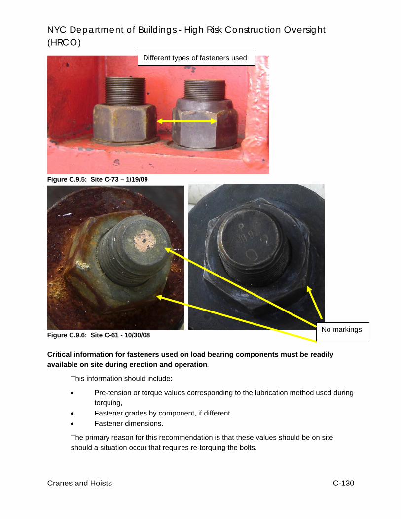
NYC Department of Buildings - High Risk Construction Oversight (HRCO)
Cranes and Hoists C-130
Figure C.9.5: Site C-73 – 1/19/09
Figure C.9.6: Site C-61 - 10/30/08 Critical information for fasteners used on load bearing components must be readily available on site during erection and operation.
This information should include:
• Pre-tension or torque values corresponding to the lubrication method used during torquing,
• Fastener grades by component, if different. • Fastener dimensions.
The primary reason for this recommendation is that these values should be on site should a situation occur that requires re-torquing the bolts.
No markings
Different types of fasteners used
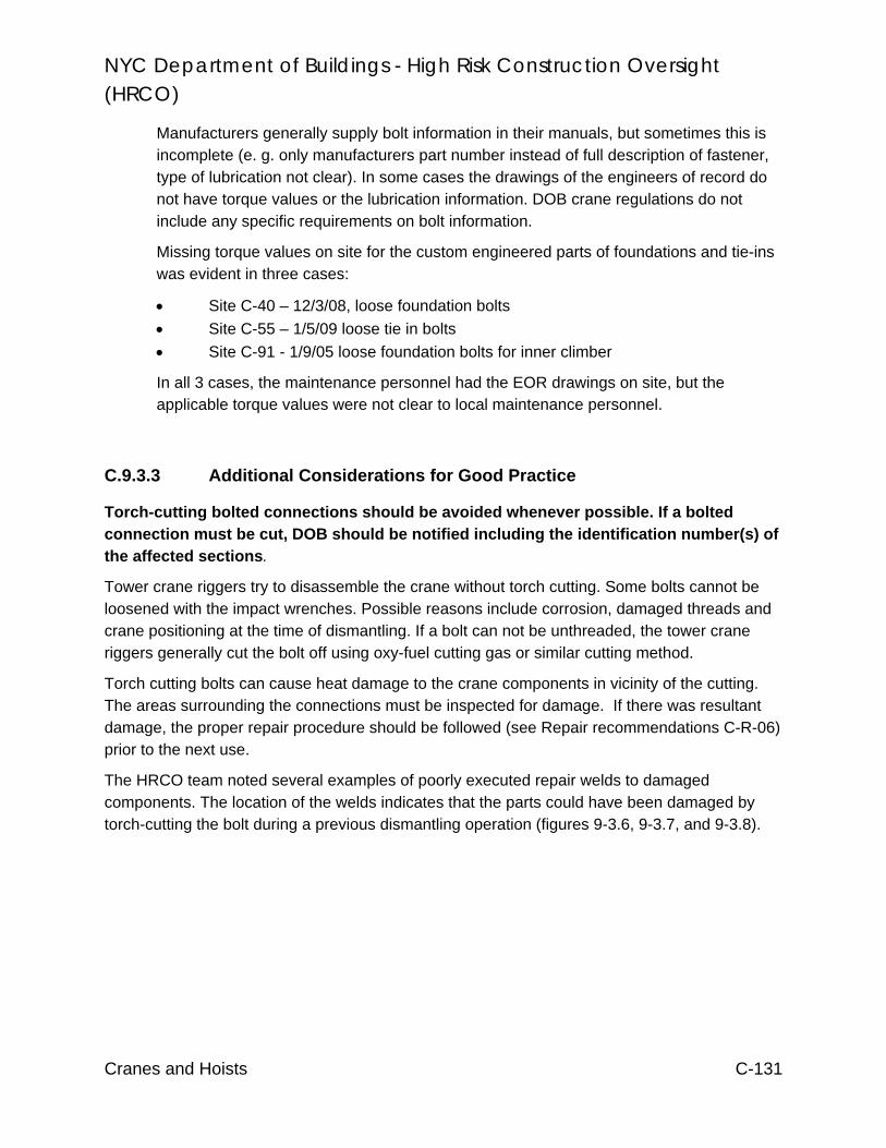
NYC Department of Buildings - High Risk Construction Oversight (HRCO)
Cranes and Hoists C-131
Manufacturers generally supply bolt information in their manuals, but sometimes this is incomplete (e. g. only manufacturers part number instead of full description of fastener, type of lubrication not clear). In some cases the drawings of the engineers of record do not have torque values or the lubrication information. DOB crane regulations do not include any specific requirements on bolt information.
Missing torque values on site for the custom engineered parts of foundations and tie-ins was evident in three cases:
• Site C-40 – 12/3/08, loose foundation bolts • Site C-55 – 1/5/09 loose tie in bolts • Site C-91 - 1/9/05 loose foundation bolts for inner climber
In all 3 cases, the maintenance personnel had the EOR drawings on site, but the applicable torque values were not clear to local maintenance personnel.
C.9.3.3 Additional Considerations for Good Practice
Torch-cutting bolted connections should be avoided whenever possible. If a bolted connection must be cut, DOB should be notified including the identification number(s) of the affected sections.
Tower crane riggers try to disassemble the crane without torch cutting. Some bolts cannot be loosened with the impact wrenches. Possible reasons include corrosion, damaged threads and crane positioning at the time of dismantling. If a bolt can not be unthreaded, the tower crane riggers generally cut the bolt off using oxy-fuel cutting gas or similar cutting method.
Torch cutting bolts can cause heat damage to the crane components in vicinity of the cutting. The areas surrounding the connections must be inspected for damage. If there was resultant damage, the proper repair procedure should be followed (see Repair recommendations C-R-06) prior to the next use.
The HRCO team noted several examples of poorly executed repair welds to damaged components. The location of the welds indicates that the parts could have been damaged by torch-cutting the bolt during a previous dismantling operation (figures 9-3.6, 9-3.7, and 9-3.8).

NYC Department of Buildings - High Risk Construction Oversight (HRCO)
Cranes and Hoists C-132
Figure C.9.7: Site C-95 – 8/28/09
Figure C.9.8: Site C-89 – 1/19/2009
Figure C.9.9: Site C-53 – 8/5/2008
Repair weld
Repair welds interferes with bolt-seat
Repair welds
Bolt not seated properly

NYC Department of Buildings - High Risk Construction Oversight (HRCO)
Cranes and Hoists C-133
DOB should investigate the use of “calibrated” pneumatic or electric impact wrenches for the exact torquing of bolts.
This is a common practice with some crane erectors in NYC. These types of tools apply shock loading to a bolt during the tightening process and are probably not exact enough to pretension a connection sufficiently without over-tightening it. A possible approach would be to request information from the OEMs and engineers of record for their respective designs.
C.9.3.4 Additional HRCO Observations
Several jurisdictions and national standards have regulations that specifically speak address bolted connections. Detailed citations are included below, and summarized in Table C.9.5.
Agency Points of Interest:
C-DAC - At least every 12 months, bolts, rivets and other fasteners for looseness, failed or significantly corroded.
California (Cal-OSHA)
- Tower crane applicant must provide a written plan that covers operation, erection, climbing, and dismantling of the tower crane. This plan must address the manufacturer’s manual and tailored to the site conditions. Further, the plan must contain the procedure for torquing all slew ring and tower section bolts.
Hong Kong - Bolts must be the correct type and quality and tightened to recommended values. - All bolts should be carefully inspected before re-use - Strongly recommended that the joint between the gear ring in the crane base and the
tower top ring be broken whenever the crane is moved to a new site and the used bolts should be destroyed.
- The tower ring should be examined for weld cracks and for flatness of the bolting surfaces when dismantled and before each erection.
Singapore - Recommends using new bolts on the bottom three sections of a tower crane at the beginning of each new use.
- Prohibit use of connecting fasteners (i.e., bolts/pins) older than eight (8) years. - All bolts/pins or connecting fasteners used in accordance to manufacturer’s design and
readily identifiable. - Random samples of all bolts/pins or connecting fasteners must undergo NDT (non-
destructive testing) for any defects. The Jurisdiction provides a table. - Random samples of all slew ringbolts used are tested for any defects. These bolts
should be taken from positions on the slew ring that are mutually 90 degrees apart and identified in some manner that is indicative of their original position.
Australia (Queensland)
- The slew ring must be split each time the crane is moved, 10% of slew ring bolts must undergo NDT. Bolts to be tested are to be selected from the slew ring by a competent person. If any cracks are detected, all bolts must be tested.
- A minimum of 10% of tower bolts must be crack tested by NDT prior to each crane erection. If any cracks are found, all tower bolts must be crack tested.
- A system that ensures all tower bolts are tested over time is preferred, however a random system of testing may also be used
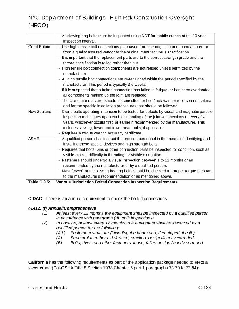
NYC Department of Buildings - High Risk Construction Oversight (HRCO)
Cranes and Hoists C-134
- All slewing ring bolts must be inspected using NDT for mobile cranes at the 10 year inspection interval.
Great Britain - Use high tensile bolt connections purchased from the original crane manufacturer, or from a quality assured vendor to the original manufacturer’s specification.
- It is important that the replacement parts are to the correct strength grade and the thread specification is rolled rather than cut.
- High tensile bolt connection components are not reused unless permitted by the manufacturer.
- All high tensile bolt connections are re-tensioned within the period specified by the manufacturer. This period is typically 3-6 weeks.
- If it is suspected that a bolted connection has failed in fatigue, or has been overloaded, all components making up the joint are replaced.
- The crane manufacturer should be consulted for bolt / nut/ washer replacement criteria and for the specific installation procedures that should be followed.
New Zealand - Crane bolts operating in tension to be tested for defects by visual and magnetic particle inspection techniques upon each dismantling of the joints/connections or every five years, whichever occurs first, or earlier if recommended by the manufacturer. This includes slewing, tower and tower head bolts, if applicable.
- Requires a torque wrench accuracy certificate. ASME - A qualified person shall instruct the erection personnel in the means of identifying and
installing these special devices and high strength bolts. - Requires that bolts, pins or other connection parts be inspected for condition, such as
visible cracks, difficulty in threading, or visible elongation. - Fasteners should undergo a visual inspection between 1 to 12 months or as
recommended by the manufacturer or by a qualified person. - Mast (tower) or the slewing bearing bolts should be checked for proper torque pursuant
to the manufacturer’s recommendation or as mentioned above. Table C.9.5: Various Jurisdiction Bolted Connection Inspection Requirements
C-DAC: There is an annual requirement to check the bolted connections.
§1412. (f) Annual/Comprehensive (1) At least every 12 months the equipment shall be inspected by a qualified person
in accordance with paragraph (d) (shift inspections). (2) In addition, at least every 12 months, the equipment shall be inspected by a
qualified person for the following: (A.i.) Equipment structure (including the boom and, if equipped, the jib): (A) Structural members: deformed, cracked, or significantly corroded. (B) Bolts, rivets and other fasteners: loose, failed or significantly corroded.
California has the following requirements as part of the application package needed to erect a tower crane (Cal-OSHA Title 8 Section 1938 Chapter 5 part 1 paragraphs 73.70 to 73.84):

NYC Department of Buildings - High Risk Construction Oversight (HRCO)
Cranes and Hoists C-135
The tower crane Applicant shall provide to the Division a written plan covering operation, erection, climbing and dismantling of the tower crane. The written plan shall address the requirements of the manufacturer's manual tailored to the site conditions where the tower crane will be installed, including the following as appropriate for either erection or operation: … The type and calibration of torque wrenches and/or belt stretchers and the procedure to be used for all tower sections and slew-ring bolts, including re-torquing after final assembly. A procedure for written verification of all slew-ring and tower section bolt torques to be maintained at the worksite or on the crane.
Hong Kong offers recommendations about the bolted connection of tower cranes in the manual “Code of Practice for Safe Use of Tower Cranes”, published by the Hong Kong Labour Department, Occupational Safety and Health Branch:
10.1.1 (c)..... Bolts of the correct size, type and quality, tightened to the recommended torques should be used at their appropriate locations. All bolts should be carefully inspected before re-use...... 10.14.5 Tower cranes are particularly severe on their slewing rings and ring bolts, and cracks have been found in many instances at the welding of the gusset plates in the tower ring. Severe accident would occur due to the fatigue failure of the bolts. It is strongly recommended that the joint between the gear ring in the crane base and the tower top ring be broken whenever the crane is moved to a new site and the used bolts should be destroyed. The tower ring should be examined for weld cracks and for flatness of the bolting surfaces when dismantled and before each erection. Lack of bearing area at the contact face of a bolt head can lead to slackness under cyclic loading, with the consequent danger of inducing fatigue cracks.
Singapore has the following requirements for tower crane bolts before each erection, as described in the “Notification for use of Tower Crane in Workplace” of the Ministry of Manpower.
7.2 Pre-installation Checks
b) If possible, use new bolts/pins or other connecting fasteners for the bottom 3 mast sections. The supplier or owner must ensure that only original load bearing members from the manufacturer are used in the Installation. A letter of undertaking shall be submitted at application.
c) Bolts/pins or other connecting fasteners of 8 or more years shall not be used
Appendix 6: Checklist for Inspection & Testing of Tower Crane

NYC Department of Buildings - High Risk Construction Oversight (HRCO)
Cranes and Hoists C-136
2) All bolts/pins or connecting fasteners used in accordance to manufacturer’s design and readily identifiable.
5) Random samples of all bolts/pins or connecting fasteners must undergo NDT (non-destructive testing) for any defects
Number of Bolts/Pins Used (excluded those used at the bottom 3
mast sections)
Sample Size Required
9 to 15 5
26 to 40 10
41 to 65 15
66 to 110 20
111 to 180 25
Table C.9.6: Bolt Test Requirements.
6a) Random samples of all slew ringbolts used are tested for any defects. These bolts should be taken from positions on the slew ring that are mutually 90 degrees apart and identified in some manner that is indicative of their original position.
27) The bolts/pins or other connecting fasteners used for the bottom 3 mast sections are new ones.
Australia (Queensland) has the following requirements for bolted connections in its “Tower Crane Code of Practice 2006”:
16.2.3 Crack testing of slew ring bolts The integrity of slew ring bolts is critical for ensuring both the machine deck and boom remain attached to the tower. Slew ring bolts may become damaged, and their effective life reduced if bolts are either under or over-torqued.
For tower cranes, where the slew ring must be split each time the crane is moved (e.g. Favco 1500), 10% of slew ring bolts must undergo NDT. Bolts to be tested are to be selected from the slew ring by a competent person. If any cracks are detected, all bolts must be tested.
All slew ring bolts on tower cranes, including self-erecting tower cranes, must undergo NDT at least every five years. The preferred system of testing is to completely remove the bolts from the slew ring and examine them by magnetic particle testing.

NYC Department of Buildings - High Risk Construction Oversight (HRCO)
Cranes and Hoists C-137
16.2.4 Crack testing of tower bolts
Tower bolts are a critical part of the crane, and permit the effective transfer of load from the crane boom to the crane base. Tower bolts may become damaged from job to job. Their effective life may also be reduced if the bolts are either under or over-torqued. While all tower bolts are high tensile bolts, some are made from extremely high grade steel and may be more susceptible to cracking A minimum of 10% of tower bolts must be crack tested by NDT prior to each crane erection. If any cracks are found, all tower bolts must be crack tested. A system that ensures all tower bolts are tested over time is preferred, however a random system of testing may also be used. A crane owner may decide to test more than 10% of bolts where deemed necessary (e.g. due to a history of cracking). The tested bolts should be identified by a method that does not damage the bolt.
In addition, all slewing ring bolts must be inspected using NDT for mobile cranes at the 10 year inspection interval.
Great Britain: The Health and Safety Executive HSE (an institution similar to the American OSHA including inspection and enforcement powers) issued a safety alert about tower crane high tensile strength bolts on 25 January 2007:
Those responsible for the installation, thorough examination, inspection, maintenance and operation of tower cranes should ensure that:
Use of correct bolt connections:
1. They use high tensile bolt connections purchased from the original crane manufacturer, or from a quality assured vendor to the original manufacturer’s specification. It is important that the replacement parts are to the correct strength grade and the thread specification is rolled rather than cut.
3. High tensile bolt connection components are not reused unless permitted by the manufacturer. Components that have been continuously immersed in water should not be reused unless subjected to 100% non-destructive testing (NDT), using appropriate techniques for the application. ......
7. All high tensile bolt connections are re-tensioned within the period specified by the manufacturer. This period is typically 3-6 weeks...
13. If it is suspected that a bolted connection has failed in fatigue, or has been overloaded, all components making up the joint are replaced. The old parts should be quarantined so that a detailed examination can be undertaken and so that they cannot re-enter service. The crane

NYC Department of Buildings - High Risk Construction Oversight (HRCO)
Cranes and Hoists C-138
manufacturer should be consulted for bolt / nut/ washer replacement criteria and for the specific installation procedures that should be followed.
New Zealand states the following requirements in the “Approved Code of Practice for Cranes” published by the Department of Labour:
10.2 (6) Inspection of new and existing tower cranes is to be in four distinct parts as follows:
Part 1: An inspection by an equipment inspector prior to erection together with inspection of any repairs found necessary. Inspections will cover (but are not limited to): .....(v) crane bolts operating in tension to be tested for defects by visual and magnetic particle inspection techniques upon each dismantling of the joints/connections or every five years, whichever occurs first, or earlier if recommended by the manufacturer. This includes slewing, tower and tower head bolts, if applicable.
Note: Any bolts found with crack-like indications shall be removed from service and destroyed. IANZ-endorsed NDT reports are required.
Part 2: The inspection and testing of the tower crane after erection and annual inspection for recertification. Inspections and testing will cover (but are not limited to) the following items. The following documentation is to be provided by the controller to the equipment inspector prior to testing commencing:
(c) IANZ-endorsed NDT report of crack testing of tower bolts.
(f) Torque wrench accuracy certificate.
The ANSI B30.3-2004 “Construction Tower Cranes” has the following recommendations for bolted connections:
Section 3-1.1.2 General Erection and Dismantling Requirements:
(d) Since crane masts or other components utilize connections with special devices or high strength bolts, a qualified person shall instruct the erection personnel in the means of identifying and installing these special devices and high strength bolts.
(f) Before reusing bolts, pins or other connection parts, they should be inspected for condition. Visible cracks, difficulty in threading a nut by hand, or visible necking down of the shank are indications of yielding or damage and reason for rejection.

NYC Department of Buildings - High Risk Construction Oversight (HRCO)
Cranes and Hoists C-139
3-2.1.2 Inspections Classification
(b) (2) Periodic Inspection. Visual inspection by an appointed person at 1 to 12 month intervals or as specifically recommended by the manufacturer or by a qualified person. Records shall be kept of apparent external conditions to provide a basis for continuing evaluation.
Section 3.2.1.4 Periodic Inspection
(a) Complete inspections of the crane shall be performed at intervals, as generally defined in Para. 3-2.1.2(b) (2) depending on its activity ....Any deficiencies, such as listed below, shall be examined and determination made by a designated person as to whether they constitute a hazard:
.... (2) loose bolts or rivets...
(c) High strength (traction) bolts used in mast (tower) connections and in connection of the slewing bearing shall be checked for proper tension (torque) at intervals recommended by the manufacturer or as suggested in (a) above. Bolts that loosen should be checked for permanent deformation or other damage. Visible cracks, difficulty in threading or unthreading a nut by hand or observable necking are reasons for replacement.

NYC Department of Buildings - High Risk Construction Oversight (HRCO)
Cranes and Hoists C-140
C.9.4 Recommendation C-17: Tracking Mobile Cranes
Require the crane user/owner of mobile cranes to notify DOB prior to the start of a job and when the crane will leave the jobsite. DOB must also be notified if there are changes in the schedule. The notification is required for all jobs that require a Certificate of On-site Inspection.
C.9.4.1 Description
Certain aspects of crane inspections are best done on an active site, such as reviewing and auditing the:
• License of operators, safety managers, riggers and other on site personnel • Crane setup including protection of the public and workers against falling
loads, out rigger support and hydraulic systems. • Comparison of the Certificate of On-site Inspection to the actual conditions • Status of rigging gear • Hoisting operations
DOB has difficulties inspecting rubber tired mobile cranes on site because of their high mobility and short job durations. Presently, DOB uses Department of Transportation (DOT) information to create daily lists that DOB inspectors use to check a certain area (“sweeps”). However, this procedure is very inefficient because the DOT permit is valid for 90 days. Thus, on any given inspection day, typically only 10% of the listed cranes are actually on site.
.
Figure C.9.11: DOB Inspecting a Mobile Crane

NYC Department of Buildings - High Risk Construction Oversight (HRCO)
Cranes and Hoists C-141
C.9.4.2 Recommendation Approach
An approach that DOB should consider is as follows:
• The user/owner notifies the 311 call center by 12:30 hours the day before the crane will start work. DOB has a call-center (“311”) that is available 24 hours 7 days per week. This is the main number for all complaints from the public and emergency calls. Therefore, a mechanism is in place that receives crane related calls.
• DOB would provide the user/owner a confirmation number • Password protect the system to guard against false notifications • Implement this recommendation incrementally (e.g. phasing in cranes with
different capacities and boom lengths – largest first).
The notification should include the following information: • Certificate of on-site inspection (CN) number (identifies the job including job
address). • CD number (identifies the crane).
Proposed start time and date. • Proposed finish time and date.
Notifications for repeated schedules should be accepted, e.g. “crane C/N 1234/08, CD 5678, will operate from Monday 1/15/09 to Friday 1/19/09 each day from 8:00 AM to 3:00 PM”. The information received by the call center could then be assembled into inspection route sheets for DOB personnel.
C.9.4.3 Additional HRCO Observations
DOB requires all cranes with a combined boom length over 250’ to be inspected by DOB on site prior to its use. The owner or user notifies DOB with a request for inspection. There is no such rule concerning smaller mobile cranes. DOB has general knowledge about a planned crane operation because the owner or user must submit a Certificate of on-site Inspection (C/N) for cranes engaged in a construction activity. The C/N includes:
• The crane’s identity via the CD number or a group of possible CD numbers • The address of the jobsite • The setup and configuration of the crane
The C/N process includes an engineering plan review of the crane’s set-up. The application for the C/N is often filed several days or weeks in advance and is valid for one (1) year. The C/N allows the user to operate the crane anytime within the specified period with no requirement to notify DOB.

NYC Department of Buildings - High Risk Construction Oversight (HRCO)
Cranes and Hoists C-142
For crane operations that utilize a public street, walkway or sidewalk, the user needs a Department of Transportation (DOT) permit. This permit is typically valid for 3 months.
DOB uses different approaches to spot inspect mobile cranes.
• In a “patrol”, DOB inspector drives around searching for operating mobile cranes. Interviews with DOB inspectors showed that this method yielded approximately 2 – 3 crane inspections per day. The success of this method depends upon the number of cranes in a certain area and the weather.
• In a “DOT - sweep”, DOB collects DOT permit information and prepares an inspection route visiting all the sites that have a current DOT crane permit. Interviews with inspectors showed that the inspectors encounter a crane that is operating or where an operator is available approximately 10 – 15% of the locations, resulting in 1 to 3 inspections per workday.
In September/October 2008, the HRCO crane team conducted a “sweep” for mobile cranes. Forty (40) jobsites were chosen randomly from the outstanding C/N list. Jobsites in the Bronx, Brooklyn, Manhattan and Queens where visited. The weather conditions where dry with mild temperatures. Table C.9.7 shows the results of that sweep. The HRCO team found the listed crane at 10% of sites. At 27.5% of the locations, a crane was available for inspection, but the CN number did not match the one listed on the spreadsheet provided by DOB based upon information contained in their database. For 62.5% of the jobsites, no crane was available (in some cases there was no sign of a construction site).
Explanation Quantity Percentage Total numbers of mobile crane C/Ns chosen for the sweep 40 100 Number mobile cranes, encountered on the sweep, which had the correct C/N number
4 10
Number of sites, where the HRCO team did not encounter the crane as described in the C/N but different mobile cranes (with different crane C/N) where encountered and inspected
11 27.5
Number of site visits, where there was no crane on site or the crane was not accessible
25 62.5
Number of sites, where the HRCO inspector could watch an ongoing crane operation on his unannounced visit
9 22.5
Table C.9.7 Results of HRCO CN Mobile Crane “Sweep”
DOB database provided that a total of 1,173 C/Ns for mobile cranes were processed in 2008. This represents the number of possible “spot” inspections that DOB could make.

NYC Department of Buildings - High Risk Construction Oversight (HRCO)
Cranes and Hoists C-143
Figure C.9.12: Crane Observed During CN “Sweep” DOB uses a call ahead/appointment system for the use of all c-hooks and outrigger beam suspended scaffolds being erected in the jurisdiction. This recommendation builds upon this effort already initiated by DOB. For instance, licensed riggers must call a specific number to provide the location and date of installation, and DOB provides a confirmation number. In addition, the NYC DOB schedules a large number of inspections via telephone in different areas, e.g. for plumbing, sprinkler or standpipe systems or for residential electrical inspections.

NYC Department of Buildings - High Risk Construction Oversight (HRCO)
Cranes and Hoists C-144
C.9.5 Hoist Recommendation H-4: ANSI Standards
Adopt the ANSI A10.5 Material Hoist standard. Regularly update regulation to reflect current versions of A10.5 (Material Hoist) and A10.4 (Personnel and Material Hoist).
C.9.5.1 Description
Hoist systems are typically categorized as follows:
Personnel Hoist: Hoist machines that only carry personnel.
Material-Only Hoist: Hoist machines that only carry materials and equipment (also called “Equipment Hoist”).
Material and Personnel Hoist: Hoist machines that carry both equipment and personnel.
Back-Structure: Supports, platforms and other systems that connect the hoist machine to the building.
National standards exist for these systems; however, these standards are not sufficiently incorporated into DOB’s regulatory scheme. The NYC DOB references the 1981 version of ANSI A10.4 for Personnel Hoists. There is no NYC reference standard for Material-Only Hoists, and while they are used infrequently (the HRCO only observed two of approximately 90 sites), it is desirable to have a recognized standard as a basis for regulations.
This recommendation proposes the adoption of ANSI A10.5 for Material-Only hoists. Also, hoist regulations should be regularly reviewed and updated to reflect any important changes in the ANSI standards. For example, the 2007 version of ANSI A10.4 contains important minimum requirement for equipment inspections not found in the 1981 version
Unofficially the contractors in NYC installing Material-Only Hoists are using ANSI A10.5 as a general guide line, because NYC does not have any regulating standard for these devices.
The lack of a clear regulatory standard complicates the inspection process. If an inspector identifies an issue with the as-built condition of a Material-Only Hoist, the contractor can challenge that the issue is subjective and is a matter of the inspector’s opinion. For example, during an HRCO site observation that happened to coincide with a DOB inspection, DOB inspector required the contractor build a ramp to the loading dock in addition to stairs that were already in place. This particular loading dock was designed to accommodate tractor trailers, not hand trucks. Though it may have been a good idea to have a ramp as well, there is no Material-Only standard in NYC to provide

NYC Department of Buildings - High Risk Construction Oversight (HRCO)
Cranes and Hoists C-145
a consist basis for these types of decisions (in this case, ANSI A10.5 would not require a ramp to a loading dock).
At a different site it was reported to the HRCO that an inspector took issue with the location of the winch on a Material-Only hoist. Upon further investigation the HRCO found that the winch would not satisfy A10.5, were that the basis for hoist regulations.
At both of the above sites, the primary complaint of the hoist contractor was that DOB inspection of Material-Only hoist equipment is inconsistent. Inspections and regulations based on a national standard will help to address this.
C.9.5.2 Recommendation Approach
Building Code requirements of hoist machines should be re-written to reflect, among other things, HRCO recommendations that DOB chooses to enact (such as Qualified Inspections). As a part of this process the current versions of ANSI A10.4 and A10.5 should be adopted and employed as the basis for all code provisions.
NYC Department of Buildings - High Risk Construction Oversight (HRCO)
Cranes and Hoists C-146
C.9.6 Recommendation H-5: Qualified Inspections
Introduce a “Qualified Hoist Inspection” Program that establishes the requirements and qualifications of the inspectors performing inspections of temporary personnel and material hoists inspections, as well as the inspection criteria and Drop Test Reports that are filed with DOB after the inspections are performed.
C.9.6.1 Description
There is an apparent lack of understanding of basic regulatory requirements within the NYC hoist industry. As an example, it is almost universally misunderstood that the “Drop Tests”, performed initially and then later at every 90 day interval or cathead jump, are actually supposed to be full inspections of the entire hoist machine and installation. This may in part be attributed to insufficient inspections, inspector qualifications and inadequate hoist inspection reporting forms (for both DOB and independent inspectors).
When the HRCO asked contractors when the last hoist inspection was performed it often resulted in some confusion. Most contractors had no knowledge when an inspector was last on site. Only 6 of 90 sites claim that complete inspections were performed in addition to the Drop Tests that are performed every 90 days and at jumping operations. None had a record.
As a result of the current industry inspection practices there were many sites which exhibited as-built equipment conditions that did not satisfy applicable codes, whether or not any form of a Drop Test inspection had been performed. In all, 46% of sites observed by the HRCO had more than 3 minor code violations or at least 1 more serious one.
Additionally it was found that 21% of sites maintained as-built conditions that did not comply with design details shown on the hoist installation drawings. One particular hoist site lacked shoring at the 3rd floor balcony that was clearly indicated on the installation drawings. The hoist had been in-service for about 9 months. In that time it underwent approximately 6 Drop Test “inspections”, none of which had identified and corrected the oversight.
Credentials
Currently in NYC all hoist inspectors, Departmental or Private Agency, require a NYC Elevator Inspector, or Director License. The qualification for this license is to successfully pass a written Elevator Inspection exam administered by NYC. The exam is essentially very similar to the nationally recognized Qualified Elevator Inspector Exam (QEI) with additional questions tailored to construction type personnel hoists from ANSI A10.4.

NYC Department of Buildings - High Risk Construction Oversight (HRCO)
Cranes and Hoists C-147
Do to the secured nature of the exam the HRCO was unable to review the content of the NYC inspector exam. The HRCO understands through discussions with past examinees that there are approximately only 4 to 6 questions devoted to hoist-specific material.
Qualifications
Currently, in order to be eligible to sit for the exam applicants must have specific elevator experience for either the Director or Inspector License. The application mentions specifically “Elevators”, as in the common permanent build-type found in any multi-story building. These are vastly different from the hoists common to the construction industry. Construction hoists ride on a mast or tower using temporary building ties to laterally support the mast and cars.
Inspections and Recording
As per applicable codes and standards (i.e. ANSI A10.4, A10.5, OSHA, and NYC Building Code) inspections are performed initially, which is prior to a newly installed hoist being put into service. Initial inspections are normally performed by a NYC - Elevator Department licensed elevator inspector. The inspection is intended to include a fairly detailed review of the as-built equipment. However, the formal Elevator Inspection Reports, the name implies, are specifically constructed for elevators. There are essentially no items on the report that support rack and pinion construction-type hoists. The one truly common item is the “Drop Test” which happens to be a requirement of both permanent building elevators, as well as construction hoists. In fact, due in part to the report form’s limitations, the construction industry in NYC does not even refer to these efforts as inspections, they simply call them Drop Tests, because that is the only readily recognizable item on the form..
C.9.6.2 Recommendation Approach
Director / Inspector Requirements
The current system of establishing Directors and Inspectors for Private Agencies is reasonable; however the qualifications should be based specifically on rack and pinion type Personnel and Material Hoist machines used in construction. Inspector qualifications are recommended to follow a similar formwork as is currently in place, but modified to be hoist-specific.
• Director Requirements
o Have a minimum of 10 years of satisfactory experience within the 15 years immediately preceding the date of the application for the exam in the supervision of the assembly, installation, maintenance, repair, design or inspection of Personnel Hoists, Material Hoists, and Personnel & Material Hoists, as well as back-structures and common platforms.

NYC Department of Buildings - High Risk Construction Oversight (HRCO)
Cranes and Hoists C-148
o Have a minimum of 5 years of experience within the 7 years immediately preceding the date of the application for the exam, if you are a NY State licensed Professional Engineer in the supervision of the assembly, installation, maintenance, repair, design or inspection of Personnel Hoists, Material Hoists, and Personnel & Material Hoists, as well as back-structures and common platforms.
• Inspector Qualification Requirements
o Have a minimum of 5 years of satisfactory experience within the 7 years immediately preceding the date of application for the exam, in the erection/installation, design, or inspection of elevators as well as back-structures and common platforms.
Qualification Exam
A Qualified Hoist Inspector exam should be developed that is specific to construction hoists. Example content is:
• 50% - question pertaining specifically to the most current ANSI 10.4 recognized by DOB.
• 20% - questions pertaining specifically to the most current ANSI 10.5 recognized by DOB.
• 20% - questions pertaining specifically to back-structures and common platforms, relevant OSHA requirements, and special NYC-DOB requirements.
• 10% - questions pertaining to incident and accident data as well as site safety information.
Inspections and Reporting
Hoist inspection criteria and intervals should be required to be performed in accordance with ANSI 10.4, 10.5, and OSHA, as well as the NYC-DOB Building Code (refer to the following section for a detailed description of these provisions)
Also, the NYC Hoist Inspection Report forms need to be revised to accommodate items specific to the rack and pinion type hoists being inspected as required by the respective specification. In other words, there should be separate forms, or at least separate section on the form, for material, personnel and material and personnel hoists. Drop Test results also need to be incorporated into these forms.
Inspection intervals would probably remain as they are currently required; once after initial installation, after every major alteration to an existing installation, after every jump up or down, and at every 90 day interval.
The inspector’s reports need to be filed following each inspection and Drop Test. A copy of each report could be forwarded to the following, for their review and record:

NYC Department of Buildings - High Risk Construction Oversight (HRCO)
Cranes and Hoists C-149
o Office of the Hoist Contractor
o NYC-DOB Hoist Department Manager
o Hoist Sealing-Engineer
o Inspecting Agency
o Hoist Equipment On-Site Log Book
C.9.6.3 Additional HRCO Observations
Applicable codes (ANSI, OSHA, and NYC) require some form of inspections, as included below. Current NYC rules and regulations regarding inspection items to be covered and when, or at what intervals, appear to be satisfactory. However, the NYC inspector qualification requirements would not satisfy most any definition of “qualified” inspector, and need to be revised.
A10.4 – Personnel Hoists
• Inspection and Tests of Personnel Hoists
o 26.1 – Acceptance Inspections and Tests
26.1.1 – Load requirements for inspection and test. In order to ensure the safe operation of new hoists, new installations or following alterations, all hoist devises, before being placed in service, shall be subjected to an acceptance inspection and a full load test in the field. The inspection and test is to determine that all parts of the installation conform to the applicable requirements of this standard, and that all safety equipment functions as required. A jump of the tower is not considered an alteration.
• 26.1.2 – Inspections and load tests as defined in 26.1.1 shall be witnessed by an inspector employed by the enforcing authority. If such a person is not available, a qualified inspector shall conduct or witness the inspection.
• 26.1.3 – Acceptance Inspections, All parts of the installation shall be inspected for conformity with the application requirements of this standard.
• 26.1.4 – Acceptance Test, Acceptance tests shall be performed on all safety devices and equipment to determine that they function in accordance with the applicable requirements of this standard.
o 26.4 – Periodic Inspections and Tests of all Installations.
• 26.4.1 – Requirements for periodic inspection and test. All operating installations shall be subjected to regular inspections
NYC Department of Buildings - High Risk Construction Oversight (HRCO)
Cranes and Hoists C-150
and test as defined by this standard and in conformance with manufacture’s recommendations. The object of these inspections is to determine that the equipment is in safe operation condition.
• 26.4.2 – Persons authorized to make periodic inspections and tests. Periodic inspections and test shall be made by a qualified inspector.
• 26.4.3 – Inspections and test periods. Periodic inspections and test of hoists shall be made at intervals not to exceed three months.
• 26.4.4 – Periodic Inspections and tests. All parts of the equipment shall be inspected and, where necessary, tested to determine they are in safe operating conditions and that parts subject to wear, such as a ropes, bearings, gears, car safety and governor parts and buffers, have not worn to such an extent as to affect the safe operation of the installation. Any such worn parts shall be adjusted or replaced.
• A10.5 – Material Hoist
• 4.2 – Initial inspections. Before the hoist is placed in service, and each time after the tower is extended, all parts of the tower or mast cage, bucket, boom, platform, hoisting machine, guys an d other equipment shall be thoroughly inspected by qualified personnel.
• 4.3 – Periodic Inspections. All sheaves, racks and pinions, guy ties, bolt connections, miscellaneous clamps, braces and similar parts shall be inspected. The inspection shall be conducted by a qualified person after the initial installation. Subsequent inspections shall be performed at intervals not exceeding one month. All parts that may compromise the system’s integrity shall be repaired or replaced.
• 15.19 – Daily inspections. All hoisting machines, including brakes, gears, levers and wire ropes, shall be visually inspected by a competent person daily. All broken, worn or defective parts that may affect operational integrity shall be repaired or replaced before start-up.
o 15.19.1 – The results of the daily inspection shall be entered into the Maintenance Records logbook, outlined in Section 23.
OSHA
• 1926.552(c)(15) – Following assembly and erection of hoists, and before being put in service, an inspection and test of all functions and safety devices shall be made under the supervision of a competent person. A similar inspection and test is required following major alterations of an existing installation. All hoists shall be inspected and tested at not more than 3 month intervals.

NYC Department of Buildings - High Risk Construction Oversight (HRCO)
Cranes and Hoists C-151
NYC Building Code
Title 26/ Subchapter 3 / Article 4 - Inspections
o 26.219 – Inspection of construction machinery and equipment, etc – The commissioner shall cause inspections to be made of machinery and equipment used for construction and excavating work, and for cableways, hoisting and rigging purposes.
o 26.220 - The commissioner shall cause all signs for which permits have been issued to be inspected at least once in every calendar year.
o 26.221 – Inspection reports. All inspection reports shall be in writing, and signed by the inspector, or the responsible individual, or the officer of the service, making the inspection; and a record of all inspections shall be kept by the department.
Title 27 / Subchapter 18 / Article 3 – Test and Interval
o 27.997 – Acceptance test, No new, relocated or altered equipment shall be placed in operation until it has been tested and an equipment use permit has been issued by the commissioner. Such test shall be made as required in section 27.999 of this article and shall be conducted by the person or firm installing, relocation or altering the equipment and shall be witnessed by a representative of the commissioner.
o 27.998 – Periodic inspection and test intervals, Every new and existing device listed in article one of this subchapter except elevators located, (i) in owner occupied one-family or two-family dwellings provided that the elevator services only the owner occupied dwelling unit and that such dwelling unit is not occupied by boarders, roomers or lodgers, or (ii) within convent of rectories which are not accessible to non-occupants on a regular basis, or (iii) within an owner occupied dwelling unit which is not occupied by boarders, roomers or lodgers shall be inspected and tested at least at the following intervals:
(d) Workers’ hoists – every three months and immediately following each increase in travel.
o 27.999 – Inspection and test requirements, Every new and existing device listed in article one of this subchapter shall be subjected to inspections and test requirements as follows:
(a) Elevators, dumbwaiters and escalators to the requirements specified in the reference standards RS 18-1
(b) Moving Walks
(c) Lifts, conveyors, and amusement devices

NYC Department of Buildings - High Risk Construction Oversight (HRCO)
Cranes and Hoists C-152
C.10 MAINTENANCE AND REPAIR C.10.1 Description
This chapter addresses issues that relate to the repairs and upkeep of the cranes operating in the jurisdiction.
Regular maintenance is a necessary aspect of safe crane operation. Repair of damaged, malfunctioning or worn components must be conducted in a manner that restores intended functional integrity. The repair and maintenance recommendation addresses the need to monitor repairs to critical components and the need to keep good maintenance records as evidence of proper crane up-keep.
The component tracking is a related aspect of maintenance and repair; with out being able to track critical crane components there is no way to document service history.
The Data Recorder (sometimes referred to as a “Black Box”) recommendation is for further study that outlines how DOB can incorporate technology to enhance the first two recommendations.
Hoist recommendations address procedures to evaluate the condition of hoist components while at a storage yard (Off-site Controls) and on-site documentation of critical information (On-site Log Book).

NYC Department of Buildings - High Risk Construction Oversight (HRCO)
Cranes and Hoists C-153
C.10.2 Recommendation C-6: Maintenance and Repair
C.10.2.1 Description
The use of appropriate repair and maintenance procedures, the selection and use of quality materials, and regular maintenance greatly influence crane safety and longevity. The present system for maintenance and repairs (including the rebuilding and modifications of crane parts) has short comings:
a) DOB typically relies on voluntary information from crane owners, users and operators for notification of a major repair. The exception being situations where the repair was either initiated by a DOB inspection or an accident reported to DOB.
b) While the practice regarding maintenance and inspection logs is apparently improving, they still are not routinely updated so that a DOB inspector can successfully audit them.
While OSHA and DOB require frequent and periodic crane inspections, there is currently no NYC or national requirement to keep inspection, repair or maintenance records for longer than 1 year. If records are available at NYC sites, they often do not include information about the person performing the procedures or a “sign-off” of the work performed. In addition, these records are often either hand written or generic forms. It is therefore difficult to determine if all required maintenance and inspections were performed.
Some rental contracts shift the maintenance and repair responsibility from the owner to other persons or firms, which includes the record keeping. For example, the owner, operator, maintenance person (“oiler”), rental customers and persons responsible for crane operations (often different persons as the job progresses) can all be involved in the maintenance and inspection process. DOB expanded the role of the “crane safety coordinator” to ensure the required safety and maintenance inspections are properly completed and recorded.
Figure C.10.1 and C.10.2 show a major boom buckling (for which there was, at the time, no specific repair requirements) and poor maintenance of a crane electrical cabinet (corroded electrodes and improper flammable liquid storage).
Figure E.10.1: From DOB incident / accident files
Figure E.10.2: Site C-18, 9/30/08

NYC Department of Buildings - High Risk Construction Oversight (HRCO)
Cranes and Hoists C-154
C.10.2.2 Repair
The Owner must notify DOB of all major structural repairs while the component is actively registered (has CD) or upon renewal if the CD lapsed. All parts (structural and major components) should be replaced with OEM parts or OEM equivalent as determined by DOB.
The proposed process is:
• Work with the industry and manufacturers to identify key components. Initially, the HRCO recommends the following: cords on mast, boom and jib sections, castings, pin connections, turn table, suspension system and A-Frame. Crane recommendation C-R-20 provides a list of components to be tracked. However, the list for this recommendation would likely include additional items. For example, the tower crane suspension system will be considered here and not on C-R-20.
• Major repairs would be identified following an accident or during standard inspections by either DOB or a qualified inspector (see C-R-03).
• Should an accident or incident occur involving a key component while operating in the jurisdiction, the Owner and User must notify DOB immediately (current regulations require this). If such happens outside NYC, then the Owner must notify DOB prior to operating the crane in the City or the next CD renewal, whichever occurs first.
• Require the manufacturer’s involvement in all such repairs (i.e., repair procedure, supply of parts and repair certification).
• Owner submits the manufacturer’s approved repair procedures to DOB. If a crane is no longer supported by a manufacturer, then the CD will not be renewed unless a Professional Engineer designs a repair procedure and certifies that the repair will essentially restore the crane to its original state and the crane is safe to operate.
• The repair will be completed by a certified person pursuant to the Manufacturer or Professional Engineer’s recommendation(s).
• A third party inspection is required after completion of the repair or modification (see the Qualified Inspectors recommendation, C-R-03).
• If a professional engineer provided the repair procedure, they must approve that the repair is pursuant to their direction.
• The inspector sends his original report to the Owner (to be filed with the crane’s maintenance file) and a copy to DOB.
• Owner notifies DOB the crane has been repaired and ready for re-inspection, if required by regulation (e.g. stop work notice filed).

NYC Department of Buildings - High Risk Construction Oversight (HRCO)
Cranes and Hoists C-155
The current regulation requires that if a crane accident occurs in the Jurisdiction, the person directly in charge of the crane or owner must notify DOB of the incident prior to moving or removing the equipment.
DOB then visits the job site and completes an initial incident/accident report, and issues a Stop Work Order (SWO) if the inspector deems the machine unsafe. In order to lift the SWO, the Owner must repair the damaged equipment, request DOB to re-inspect, and then they may place it back into service when DOB lifts the SWO. For instances that occur outside the City, there is no such requirement.
Figure C.10.1 above shows a crane for which the heel section of the boom was buckled due to malfunctioning equipment. The accident occurred in January 2005. DOB file shows the section as being repaired, but did not include the manufacturer’s repair procedure. The SWO was lifted after DOB re-inspected the crane.
The HRCO reviewed two situations where a tower crane sustained damage while either being assembled or in place. The first incident had three lacings damaged by the hoist rope (Figure C.10.3), and the second had a bent lacing and cracked weld of unknown cause (Figure, C.10.4).
In the first instance, the Owner, via the Engineer of Record, submitted a Manufacturer’s procedure for the repair, made the repair, and the SWO lifted. The CD folder does not contain documentation regarding the actual repair.
The boom section shown in picture in Figure C.10.4 depicts a situation where the Owner elected to replace it rather than place it in situ. Under the current system it can not necessarily be determined whether the replaced section will be properly repaired before being returned to service.
Figure C.10.3: Site C-80 – 9/8/08 Figure C.10.4: From DOB incident / accident files

NYC Department of Buildings - High Risk Construction Oversight (HRCO)
Cranes and Hoists C-156
The HRCO team also witness five instances of poor welds near the bolted connection (Figure C.10.5). This could be could be indicative of flame cutting bolts (the practice of removing difficult bolts by cutting with a torch). These welds may interfere with the surface of bolts, and put bending stresses on the bolt endangering the connection.
There are web sites that portend to manufacture and sell OEM parts that actually have no relationship with the OEM. These parts may be inferior to the OEM parts (see Component Tracking Recommendation, C-R-20).
The HRCO team observed a crane that appeared to have been repaired (heel boom section) with non-OEM manufactured parts. The lacings do not have taper that is consistent with the original equipment. Structural member details, such as tapers, are designed by manufacturers to support design objectives such as fatigue life. Figures C.10.6 and C.10.7 illustrate these points. In figure C.10.6, the catwalk differs between the two boom sections. One has a toe guard and a different grating. While Figure C.10.7, the lacing attached to the cord has a crimp in it versus having a sloping angle that manufacturer typically use.
ASME B30.3 also addresses this point by stating that replacement parts should ordinarily be obtained from the original equipment manufacturer or at least equivalent to OEM parts.
Site C-89 – 1/19/09 Site C-95 – 8/28/09 Site C-95 – 8/28/08
Weld too large Repair
Weld
Figure C.10.5: Poor repair welds

NYC Department of Buildings - High Risk Construction Oversight (HRCO)
Cranes and Hoists C-157
C.10.2.3 Maintenance
Increase the written maintenance and inspection log requirements to provide more complete records of the work performed on each crane.
Strengthen the maintenance/inspection log book requirement for tower and large mobile cranes operating within the jurisdiction and that are on a job site for a minimum specified duration (i.e., longer than a continuous 3 months period on-site).
The proposed process is:
• Users maintain the inspection and maintenance logs while the crane is on site, and DOB audits them. The information that should be included in the logs are the date and time the work was performed, inspection items required by RS19-2, any additional OEM recommendations, items that DOB may request and the initials of the person performing the work.
• Designate the Crane Safety Coordinator responsible for the upkeep of the crane’s maintenance and inspection records (they do not need to perform the work – just ensure that it is completed).
• During dismantling, DOB would audit the logs a final time. The user would send the logs back with the crane to the owner, and the owner would keep them with the crane’s maintenance file.
• The Owner would fully inspect the crane upon its return and file the completed check list and the maintenance and repair work performed with the crane’s maintenance and repair file (these will available during the annual CD inspection).
• The Owner would certify that the crane is ready and fit to return to service.
Figure D.10.6 - Site C-88 – 10/17/08 Figure D.10.7 - Site C-88 – 10/17/08

NYC Department of Buildings - High Risk Construction Oversight (HRCO)
Cranes and Hoists C-158
This procedure would allow the Third Party Inspector to review the file at the annual inspection and make note of any troublesome trends or repairs. However, if there is a gap in the log and it arose due to the crane operating outside of New York City, the Owner should not be penalized for not having proper logbook entries. However, all repairs to structural components must be included in the crane’s maintenance file.
DOB inspectors review logbook entries and have issued violations for not maintaining them on site. The Owner is not currently required to maintain records on a particular crane or certify that it is ready and fit for service.
Maintenance and inspection issues represented 55% of the issues that the HRCO team noted (see graph in Figure C.10.8). A good example is figure C.10.2 as it shows a battery compartment (typically a closed space) with a flammable liquid. An inadvertent spark from the battery could lead to a crane fire.
Crane Issues
Maintenance and Repair (57%)
Rigging, Operations, Other (43%)
Figure C.10.8: Inspection and Maintenance Issues
There were at least six (6) situations in which the crane maintenance (tower and mobile) were severely lacking (see Figure C.10.9). One of the most egregious examples was a large mobile crane that used a golf sock, duct tape, bungee cords and rubber bands to assist the operator run the crane.
Maintenance/Inspection log updates tend to be inconsistent. The team tested 17 sites and 7 had inadequate logs, and the available logs had limited or no information about repairs. The latter point may be indicative that no repairs were made.

NYC Department of Buildings - High Risk Construction Oversight (HRCO)
Cranes and Hoists C-159
Figure C.10.9: Maintenance Issues
Site C-89, 9/25/08 – the operator needs, a golf sock, bungee cords, rubber bands and duct tape.
Site C-29, 7/11/08 - The electrical cabinet is tied closed.
Site C-61, 11/5/08, the insulation on the electric slip ring is worn.
Site C-62, 8/22/08, electric wires, come-alongs and alignment pins left on tower crane platform.
The wire is holding the aviation light.
Site C-88, 10/17/08, this shows a panel in the operator’s cabin
Site C-18, 9/30/08, this clutch assembly has been over -greased, which could cause the clutch to fail should it migrate to the friction plate
Site C-95, 9/11/08, a hydraulic nipple is leaking.

NYC Department of Buildings - High Risk Construction Oversight (HRCO)
Cranes and Hoists C-160
In one of the industry meetings, the participants noted that they typically do not provide the logs to the Owner at the end of the job, nor do the Owners request them. A number of crane owners said that such logs have limited value as they perform a complete inspection upon the crane’s return.
Require a logbook for mobile cranes (short term rental) showing maintenance and repair modifications.
The owner would include date and person performing each procedure. The log should start with the date the crane was first registered in NYC and would follow the crane.
During the industry meeting, some Owners mentioned that they keep maintenance files for each of their cranes, and some did not. These logs would be reviewed by the Qualified Inspector during the annual registration process. The inspector would note any concerns in the repair/maintenance history on the annual report. The Owner would keep each of the annual inspection forms in the crane’s maintenance file.
C.10.2.4 Additional Considerations for Good Practice
Contractors should keep the tower crane pit free from water and debris.
The tower crane foundation pit is typically one of the lowest points at a job site, and as such will collect water and debris over the period that the tower remains on site. The foundations typically have steel components and as such are susceptible to rust so water egress and accumulation should be discouraged.
DOB inspectors have required various contractors to pump out the water from the pits. One such case was Site C-89 – 10/28/08.
Below are pictures of tower crane pits that either had water or debris in them (Figure C.10.10 to 12). Five tower crane foundation pits (three shown below) contained water and debris; this presents a corrosion issue and rendered inspection of the foundation integrity difficult. In the winter, ice formation could adversely affect the steel of the mast section as well as bolted connection.

NYC Department of Buildings - High Risk Construction Oversight (HRCO)
Cranes and Hoists C-161
Based upon further review, DOB could approve repair facilities, e.g. OEM approved facilities for different makes or models of cranes.
An established set of criteria would need to be developed to approve non-OEM facilities. Proposed criteria should include, but not limited to, the following:
Figure D.10.12: Site C-89 – 10/28/08 The HRCO team made two visits to this crane (also 1/19/09) and each time the foundation pit contained water.
Figure D.10.10: Site C-10 – 3/5/09 The HRCO team made three visits to this crane (also 8/16/08 and 1/26/09) and each time the foundation pit contained water and debris.
Figure D.10.11: Site C-13 – 1/26/09 This tower crane contained frozen water .

NYC Department of Buildings - High Risk Construction Oversight (HRCO)
Cranes and Hoists C-162
• Certified welders on staff with experience in the type of metal and procedures required by OEM. DOB requires that all welding repairs be completed by a certified welder. The City certifies welders based upon set requirements (see Regulation section).
• The repair personnel received factory (OEM) training on the particular make and model of crane requiring repair.
• Personnel has maintenance and repair experience with the make and model of crane. • The company has access to manuals for the crane.
C.10.2.5 Additional HRCO Observations
Several jurisdictions and national standards have regulations that specifically address repairs and maintenance. For example:
Repairs
Cal-OSHA addresses the repair recommendation in part in Title 8, Chapter 4, Subchapter 7, Article 100: “§5035. Damaged Booms (a) Prior to further use, boom sections or boom suspension components that have been damaged shall be repaired, restoring them to not less than the capacity of the original section or components. (b) Repairs to critically stressed members of a boom or boom extension, such as a boom chord, mast chord, or boom sections, shall be performed in accordance with the manufacturers’ or certified agent’s recommendations.”
Singapore has a similar procedure as outlined in this recommendation. If a structural member requires repair, the company that intends to carry out the repair must notify the regulator three (3) days prior to the work and the work must be performed by an approved crane contractor and it must follow the manufacturer’s recommendations.
Maintenance
Cal-OSHA requires the employer to create a written plan that addresses the requirements of the manufacturer's manual tailored to the site conditions, including the following (Title 8, Section 1938, Chapter 5, Part 1 §7370-7384): • “Inspection responsibilities of supervisors, inspection intervals and what is to be
inspected, i.e., a written crane inspection program. • A written crane maintenance and preventive maintenance program.”
Washington State requires the Crane certifier (WAC 296-155-53200) to: “(1) The accredited crane certifier must review the following documents as part of the crane certification process: (a) Crane maintenance records of critical components to ensure
maintenance of these components has been performed in accordance with the manufacturer's recommendations.

NYC Department of Buildings - High Risk Construction Oversight (HRCO)
Cranes and Hoists C-163
(b) Crane periodic and frequent inspection documentation.”
And under WAC 296-155-53114 “Accredited crane certifiers are required to maintain complete and accurate records pertaining to each crane of all inspections, tests and other work performed as well as copies of all notices of crane safety deficiencies, verifications of correction of crane safety deficiencies, and crane certifications issued for the previous five years and provide these records to the department upon request. Failure by an accredited crane certifier to maintain required records may result in accreditation suspension or revocation.”
Australia requires a maintenance log book to be transfer with ownership. The regulation says (cited from Tower Crane Code of Practice 2006 Handbook):
“A crane service record, such as a maintenance logbook, of the significant events concerning the safety and operation of the crane must be kept and readily available. The records must be easily understood, and written in plain English. Records may be kept in any suitable format, and must be transferred with ownership of the crane. All entries in the maintenance logbook are to:
(a) clearly describe the work undertaken and parts replaced;
(b) be dated;
(c) note the name of the person carrying out the work; and
(d) be signed by the person carrying out the work. Documentation stating that the crane has been inspected by a competent person, and is in a safe and satisfactory condition, should be readily available. The checks, adjustments, replacement of parts, repairs and inspections performed, and all irregularities or damage concerning the unit’s safe use, must be recorded. In addition, all complete routine, annual inspection and 10-year major inspection reports must be maintained and made available for examination as required.”
British Colombia, Canada requires crane owners to maintain a log from cradle to grave for each crane.
Maryland’s proposed regulation requires the employer to maintain daily inspection records for one (1) year and the annual reports for three (3).
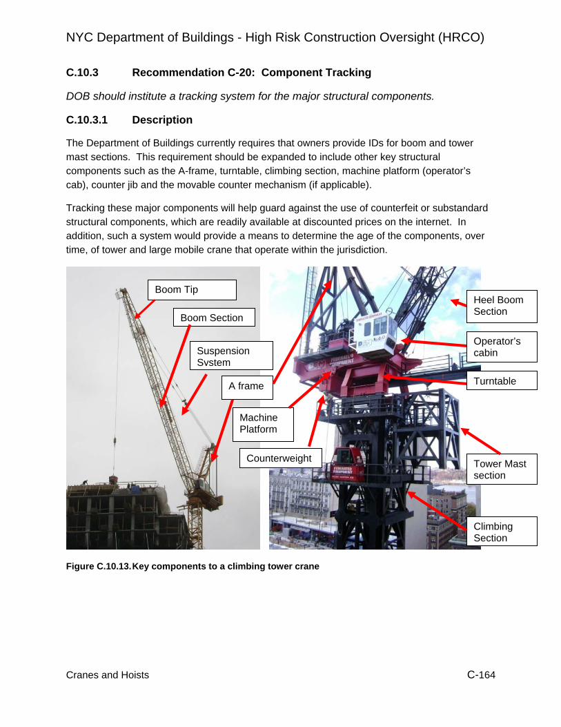
NYC Department of Buildings - High Risk Construction Oversight (HRCO)
Cranes and Hoists C-164
C.10.3 Recommendation C-20: Component Tracking
DOB should institute a tracking system for the major structural components.
C.10.3.1 Description
The Department of Buildings currently requires that owners provide IDs for boom and tower mast sections. This requirement should be expanded to include other key structural components such as the A-frame, turntable, climbing section, machine platform (operator’s cab), counter jib and the movable counter mechanism (if applicable).
Tracking these major components will help guard against the use of counterfeit or substandard structural components, which are readily available at discounted prices on the internet. In addition, such a system would provide a means to determine the age of the components, over time, of tower and large mobile crane that operate within the jurisdiction.
Figure C.10.13. Key components to a climbing tower crane
Heel Boom Section
Operator’s cabin
Turntable
Tower Mast section
Climbing Section
A frame
Counterweight
Machine Platform
Boom Tip
Boom Section
Suspension System

NYC Department of Buildings - High Risk Construction Oversight (HRCO)
Cranes and Hoists C-165
C.10.3.2 Recommendation C-R-20
Implementation of this recommendation should include the following actions:
• DOB should identify a minimum list of components that require a unique ID and marked as noted below.
• Each major load bearing component or subassembly of a crane must carry a unique component identification number (ID)
• The ID must be attached to the component in a permanent and durable fashion. The ID must be easily readable when the component is stored unassembled on the ground. In addition, it must be possible to read the number while the machine is erected (i.e., an inspector can read it while climbing on the machine).
• The Owner should submit a list of the components mentioned above together with their CD application
• Like boom and mast sections, the structural components that are listed in this recommendation should require annual or pre-assembly NDT.
DOB should identify a minimum list of components that require a unique ID and marked as noted above.
Major components/assemblies generally have the following qualities:
• Component / assembly can easily be removed (pinned or bolted connection, hoses carry quick-disconnects, electrical wiring has plug connections)
• Weight of component on crane (not derrick) or assembly generally exceeds 600 lbs • Is a load bearing component
Normally removed during transport to a jobsite
The HRCO proposes the following preliminary lists based in part on input from industry outreach meetings. However, DOB should evaluate this list and continue to consult with industry representatives before finalizing the lists.
Tower cranes: • The machine deck / counter jib carrying hoist drums, diesel engine etc. • Other counter jib sections • The operator’s cabin when detached from the machine platform for transport • Tower mast sections • Tower top sections • Jib sections • Boom sections including heel and tip • The A-Frame, if the A-frame is disassembled during transport, than the
subcomponents receive individual numbers • The turntable and the structures to mount it to the tower and to the crane top, if these
are detachable. • The climbing frame / climbing mechanism

NYC Department of Buildings - High Risk Construction Oversight (HRCO)
Cranes and Hoists C-166
• Crane parts of the Foundation like tower bases or base frames for inner climbers
Mobile cranes: • The basic crane • Lattice boom sections including heel and tip • Detachable or folding jib sections and their segments • Boom extensions, jib extensions and their segments • The A-frame
Derricks: • Mast sections, poles and other uprights • Boom sections including heel and tip • Boom extensions, • Major components of the A-frame, all stiff legs, • Junctions, seats and base plates exceeding 600 lbs.
If a crane has an irregular design that includes additional load bearing components or subassemblies, DOB should decide the components to be tracked for that individual crane prototype.
Each major load bearing component or subassembly of a crane must carry a unique component identification number (ID).
DOB should consider using a format of “xxxxx-yyyyyyyyyyyyyyy” The first 5 digits [“x”] is the CD (Certificate of Operation) number of the crane. If the CD has less than 5 digits, preceding digits are “0” (example CD 3456 will be “03456”). The following 15 positions (“y”) can be chosen by the crane owner to represent the component of that crane as long as that part of the ID is unique within the crane.
This should allow the owner to keep an already existing internal numbering system in place by inserting the CD number in front of the already numbered component. For example, an owner uses the number ABC-TT-1 (for company ABC, turntable and 1 as the number) on a crane with the CD number 2345. The new ID would become 02345-ABC-TT-1, and hence preserve their current system. The recommendation does not solely rely on existing systems for the following reasons:
• The CD number assures that the number is unique within NYC. • The CD number allows all of the individually tracked parts to initially be associated as
a single crane. While some tower and jib sections are interchanged more often, the main components typically stay with the same machine. The inclusion of the CD number allows inspectors to more easily identify parts, which were not part of the original CD.
DOB requires identification numbers on crane’s boom, jib and tower sections (DOB Issuance #536), but the numbers only have to be unique to the crane equipment owner. Crane owners use individual numbering systems to track their components, and there appears to be no consistent system within the industry.

NYC Department of Buildings - High Risk Construction Oversight (HRCO)
Cranes and Hoists C-167
Most manufacturers today use a manufacturer specific and unique worldwide numbering system for their crane components. However, there could be older pieces of equipment or machines and components without such markings.
Figure C.10.14. Site C-109 – 1/29/09
Figure C.10.15. Site C-89 – 1/21/09 The ID must be attached to the component in a permanent and durable fashion. The ID must be easily readable when the component is stored unassembled on the ground. In addition, it must be possible to read the number while the machine is erected (i.e., an inspector can read it while climbing on the machine).
Additional details for the ID’s could include that for painted numbers the ID has to be non fading and in a contrasting color and at least 3” high. For a type plate, the number must
ID by manufacturer (plate with cut-out numbers)
ID by crane owner (felt pen)
ID by crane owner (stencil, spray paint)
ID by crane owner, (weld), number “098” differs from stencil

NYC Department of Buildings - High Risk Construction Oversight (HRCO)
Cranes and Hoists C-168
be at least 2” high, if engraved and 3” high if printed, and the color of the type plate must be of contrasting to the surrounding area (figures 10.14 and 10.15).
In some cases, e.g. on a turntable of a tower crane, the number must be attached twice at different locations to allow reading while the turntable is stored on the ground and while an inspector climbs through it.
DOB issuance # 536 provides rules regarding the numbering. In this rule the “durability” of the ID number is of major concern. For reasons of structural integrity, the HRCO prefers painted numbers when the numbers are not installed by an OEM or its representative.
Sophisticated tagging systems e. g. RFID tags or bar-codes are available and have been used in the construction industry. One crane manufacturer is considering using RFID tags for part serial numbers. These types of tags are machine readable with a handheld device. The main advantages are reading speed and the exclusion of human error in the data input.
The team encountered tags and type plates that were hard to read. Some of the IDs are painted on conforming to issuance #536 (see figures C.10.16 and C.10.17).
Figure C.10.16 Site C-73 – 1/19/09 Figure C.10.17 Site C-35 – 11/19/09
The Owner should submit a list of the components mentioned above together with their CD application. The list should include the following for each component:
• The manufacturer • OEM part serial number, if available, • Type of component • Year of manufacture • Previous owner including owner’s address if the application is the first one for the
owner. • Applicants’ chosen DOB ID numbers.
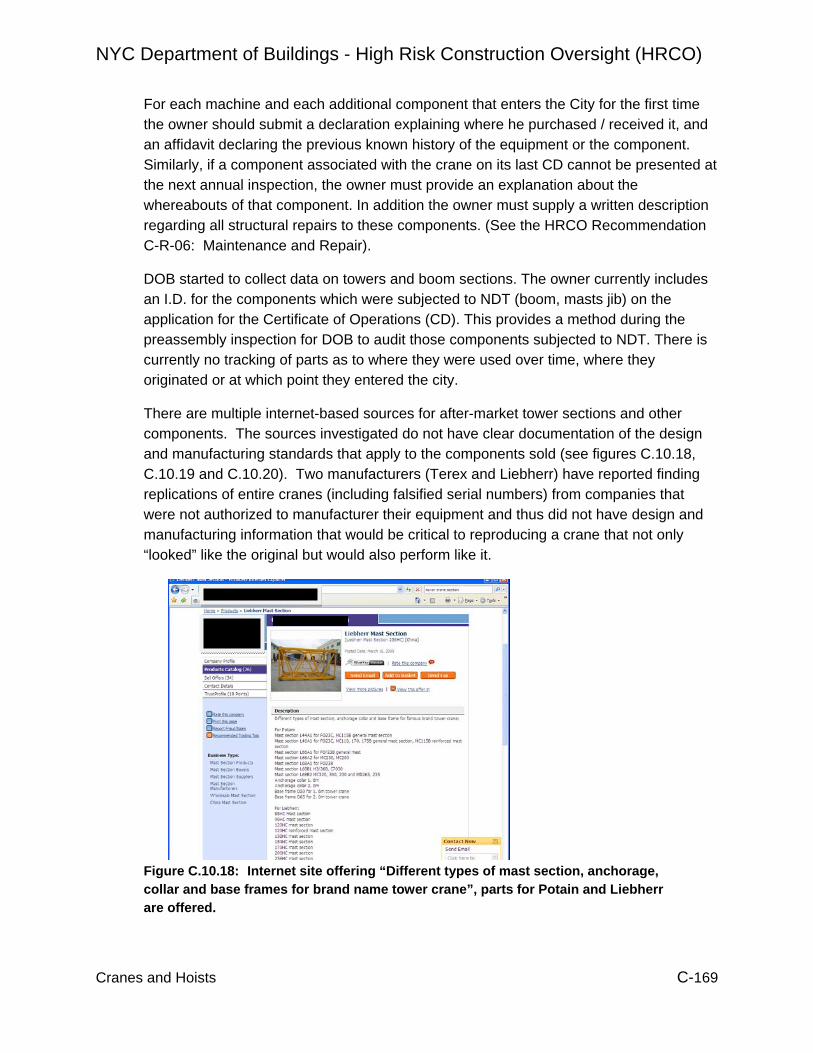
NYC Department of Buildings - High Risk Construction Oversight (HRCO)
Cranes and Hoists C-169
For each machine and each additional component that enters the City for the first time the owner should submit a declaration explaining where he purchased / received it, and an affidavit declaring the previous known history of the equipment or the component. Similarly, if a component associated with the crane on its last CD cannot be presented at the next annual inspection, the owner must provide an explanation about the whereabouts of that component. In addition the owner must supply a written description regarding all structural repairs to these components. (See the HRCO Recommendation C-R-06: Maintenance and Repair).
DOB started to collect data on towers and boom sections. The owner currently includes an I.D. for the components which were subjected to NDT (boom, masts jib) on the application for the Certificate of Operations (CD). This provides a method during the preassembly inspection for DOB to audit those components subjected to NDT. There is currently no tracking of parts as to where they were used over time, where they originated or at which point they entered the city.
There are multiple internet-based sources for after-market tower sections and other components. The sources investigated do not have clear documentation of the design and manufacturing standards that apply to the components sold (see figures C.10.18, C.10.19 and C.10.20). Two manufacturers (Terex and Liebherr) have reported finding replications of entire cranes (including falsified serial numbers) from companies that were not authorized to manufacturer their equipment and thus did not have design and manufacturing information that would be critical to reproducing a crane that not only “looked” like the original but would also perform like it.
Figure C.10.18: Internet site offering “Different types of mast section, anchorage, collar and base frames for brand name tower crane”, parts for Potain and Liebherr are offered.

NYC Department of Buildings - High Risk Construction Oversight (HRCO)
Cranes and Hoists C-170
Figure C.10.19: Website offering tower mast sections “generally used in Potain tower crane” and “mast section used in Liebherr tower crane”.
Figure C.10.20: Website offering mast section that “With the original technique from Potain and Liebherr… can match perfectly with the original tower cranes”.
On 7/29/07 boom section # B7-1953 of a lattice boom mobile crane was severely damaged in an accident. The crane CD was revoked. Several weeks later the crane was put back into operation with a renewed CD. This time boom section #B7-1953 was

NYC Department of Buildings - High Risk Construction Oversight (HRCO)
Cranes and Hoists C-171
missing on the NDT report and CD. In 2008, the crane received a CD including a boom section numbered B7-1953. From the CD file, it is not clear that this boom section was damaged in an accident and probably exchanged or repaired. Neither CD nor the materials in DOB accident file provide information regarding the origin of B7-1953. This provides an example of the value of component tracking, but that it must also be used in conjunction with clearly communicated inspection (C-R-6) and accident reports (C-R-18).
Like boom and mast sections, the structural components that are listed in this recommendation should require annual or pre-assembly NDT.
The NDT testing will be performed by approved testing agencies, specializing in that field. These agencies should visually check the complete assembly and not only the welds. During annual inspections and pre assembly inspections, inspectors review the NDT results and note the IDs of all components that will later be checked against DOB database.
DOB inspectors currently verify that the same tower, boom and jib sections that were subjected to NDT are used during a machine assembly. In addition, NDT results of these parts are reviewed at annual inspections.
The HRCO team conducted a detailed review of NDT reports of three tower cranes. One such review indicated that 2 out of 8 base plates on one tower section failed the NDT test. DOB requested additional information on this section prior to allowing the owner to use it (site C-95, NDT testing 8/20/08). This is an example where being able to track components helped ensure the section was acceptable prior to it being used.
C.10.3.3 Additional HRCO Data
The HRCO team did not find any US municipalities that require a unique ID system for crane components, and there is no mandated crane or construction equipment registration in the United States.
The National Equipment Register (NER) offers a database for the registration of construction heavy equipment. The data is used as a tool to identify and recover stolen equipment. The participation in the database is voluntary, and privacy agreements allow NER to only provide information whether a piece of equipment is stolen. The NER cooperates with and is supported by the insurance industry. A similar system “CESAR” is used in Britain.
Hong Kong recommends the identification of tower crane parts, in its publication “Code of Practice for Safe Use of Tower Cranes” of in the Hong Kong Occupational Safety and Health Branch of the Labour Department:
“7.1 Identification 7.1.1 The crane should have a permanent durable plate bearing the manufacturer's
name, machine model, serial number, year of manufacture and weight of the unit for identification purpose.

NYC Department of Buildings - High Risk Construction Oversight (HRCO)
Cranes and Hoists C-172
7.1.2 Every major structural, electrical and mechanical component of the machine should have a permanent durable plate bearing the manufacturers' name, machine model number, serial number, year of original sale by the manufacturer and weight of the unit. Besides, identification numbers should be clearly marked on all basic removable components and attachments of the machine (such as counterweights etc.) to show that they belong to that machine. It is important that these components should be used only on that machine or identical models or equipment for which they were specifically intended by the manufacturer.”
Singapore has the following requirements regarding the identification and numbering of tower crane parts explained in “Procedures for the Type Approval of Tower Crane” Rev. 1-04 published by the Ministry of Manpower. For each individual tower crane the owner must supply the following:
“LIST OF COMPONENTS:
1. This list may be used by an inspector to verify the components installed on the tower crane and the configuration(s) in which the tower crane may be installed.
2. The list shall include the identification / part / serial number of all components used for the crane for all possible combination of tower masts, jibs and all other components that are or will be used in Singapore. The components shall include but not limited to the following: a. Undercarriage (including fixing angles) b. Tower Mast Section c. Climbing Equipment d. Slewing Platform or Turntable e. Tower Head (Cathead) f. Counterjib (including stay rods) g. Main Jib (including stay rods) h. Winches / Motor i. Braking Mechanism j. Rope / Trolley Pulleys k. Specifications of Wire l. Accessories that affect the structural and integrity of the crane during operation
3. The component list shall also include drawings corresponding to the components listed above.
4. Applicant shall submit the component list in write-once media “ New Zealand requires tower crane components to be marked, which is verified during inspections:
“Part 10: Tower cranes 10.2 Additional requirements
In addition to the requirements in part 10.1 and part 3: Operational requirements for controllers, the following are also required: (6) Inspection of new and existing tower cranes is to be in four distinct parts as follows:
Part 1: An inspection by an equipment inspector prior to erection together with inspection of any repairs found necessary.
Inspections will cover (but are not limited to): (d) All parts to ensure they are marked for identification purposes. “

NYC Department of Buildings - High Risk Construction Oversight (HRCO)
Cranes and Hoists C-173
C.10.4 Recommendation C-22: Data Recorder - “Black Box” (Further Study)
Based upon further study, DOB should consider the use of data recording devices that will provide critical information regarding the operation of cranes within the jurisdiction.
C.10.4.1 Description
A data recorder or “black box” collects data from sensors (e. g. load indicator, limit switches, position of operator controls etc.) and stores them together with a time and date stamp. The stored data can then be read-out and analyzed outside of the crane (e.g., on a Personal Computer). The data is normally used for maintenance purposes, collect statistical data about machine performance, accident investigation / prevention and monitoring crane operations.
For cranes, the use of data recorders outside of the field of crane maintenance is relatively new. However, the technology has evolved to a point that the potential for general purpose data recorders (as are commonly used on other types of machines) are a practical reality.
The primary uses for construction cranes that warrant further study are:
• Collect and store operational data to establish the number of “stress cycles” a crane accumulates. This information would typically be used to determine the remaining fatigue life of critical load bearing components.
• Collect and store crane overload or shock load events. This information could be used to trigger a special inspection of the crane.
• Collect and store operational data that allows the reconstruction of the crane movements and loads that precede an accident. This reconstruction can be based on two groups of technologies: data recorders (“black box”) and video taken by cameras positioned on the crane.
C.10.4.2 Recommendation Approach
Implementation of this recommendation should include the following actions:
• Require a device to be installed that counts and records stress cycles.
• Require the installation of devices that record events, where the crane was overloaded (load moment or line pull) and records such events together with the date and time of the event. If a crane is overloaded, it should be inspected before operation recommences.
• Installing data recorders that record crane movements, operator inputs and video taping crane operations are also possible additions to such a system.

NYC Department of Buildings - High Risk Construction Oversight (HRCO)
Cranes and Hoists C-174
Require a device to be installed that counts and records stress cycles for all tower and large mobile cranes.
Fatigue is a primary design criterion for cranes. Typical fatigue designs provide for decades of service. However, there are currently a number of cranes operating in NYC that are over 30 years of age, and which may be approaching the fatigue limits of their design. For these cranes, regular inspections are the default defense against fatigue failures, since there is no reliable way in which to “back calculate” how many stress cycles the cranes have been exposed to (see C-14, Older Equipment).
For new cranes a data recorder that maintains a running tally of stress cycles would eliminate much of this guess work. This data would need to be incorporated into the component tracking system.
Most modern large cranes are controlled by a PLC (programmable logic controller) that reads inputs from sensors and operator inputs, evaluates these inputs and then actuates drives and other outputs accordingly. Some crane PLCs already include data recorders for maintenance purposes or include a modular PLC system that is designed to be used with a data recording device.
The Building code RS19-2 requires a load indicator for some mobile cranes, so these cranes normally have a load cell already installed. For all tower cranes a maximum load indicator is required, which is often realized by the installation of a load cell.
Load indicators and recording devices supplied by manufacturers vary significantly and most may require modification to serve the purpose of tracking stress cycles. Provision of suitable data recording equipment could be made a part of the Approved Manufacturer process. Aftermarket data recorders are also available as an alternative to manufacturer installed systems.
Require the installation of devices that record events, where the crane was overloaded (load moment or line pull) and records such events together with the date and time of the event. If a crane is overloaded, it should be inspected before operation recommences.
When a crane is overloaded, load bearing components of its structure (e.g. boom, tower, and jib) or of the hoisting apparatus (e.g. wire ropes, shafts of hoisting winches) can be overstressed. These components can become deformed, bent, or cracked. In addition the structure can become misaligned putting additional stresses on the surrounding parts.
In an extreme case, the deformed / cracked part fails catastrophically when it is overstressed. In other cases, the damage caused by the overstressing is not that apparent but components are weakened and can possibly fail at a later time. Therefore, a thorough inspection of the crane is needed after such an event.
A crane can be overloaded for several reasons. While load limiting device help protect the crane, there are instances that they have limited affect, such as:

NYC Department of Buildings - High Risk Construction Oversight (HRCO)
Cranes and Hoists C-175
• The operator tries intentionally or unintentionally to lift a load, that is too heavy for the crane. This situation is in most cases covered by a load limiting device on modern cranes. These devices in most cases act quickly enough and shut down the hoists before any structural damage happens.
• The crane is shock loaded for example by pulling loads out of upper stories of buildings, or on demolition jobs where a container is filled with debris. Load limiters do not protect a crane from the acceleration forces or overloading the crane in these situations.
• The load gets caught or entangles in a collision with another object during hoisting. While a load limiter can give some protection in this situation, the load could already have been accelerated to a speed that causes damage to the crane even so the hoist shuts off.
The occurrence of an overload or shock load situation should be noted in the crane maintenance and inspection log. Further, the results of the special inspection should remain with the crane in its maintenance file.
DOB requires tower and mobile cranes with combined booms exceeding 150’ have at least a load indicator installed. Many of these indicators or PLCs have output connections for warning lights and/or acoustical devices that could be used to trigger a recording device. Most modern cranes are PLC controlled and include a load moment indicator. These could be programmed to either record overloading events or switch an output in case of an overload, that then can trigger a recording device.
If the overload recorder is tamper-proof, it could be used during an accident investigation to indicate if the crane was overloaded at the time of the accident.
Installing data recorders that record crane movements, operator inputs and videotaping crane operations are also possible additions to such a system.
The data recorder would monitor crane movements and operator input. In some PLC controlled cranes, most inputs needed for such a recording are already available in the crane PLC as inputs. The PLC program would have to be adapted to write this data to a recording device.
This use of data recording technology is closest in concept to the “black box” used in aviation. It provides operational data that could be used to identify actions preceding an accident.
A review of DOB cranes and derricks accident files identified two particular accidents for which witnesses show little cooperation or have difficulties recalling the string of events that led to an accident. The data recording system (and potentially augmented with video recording) would provide a more reliable accounting of events.

NYC Department of Buildings - High Risk Construction Oversight (HRCO)
Cranes and Hoists C-176
C.10.4 .3 Additional HRCO Data
The HRCO team did not find any jurisdictions that require the use of data recording devices on cranes. However, several require load limiting devices and if paired with a data recording device, a jurisdiction would know if an overload situation occurred.
The C-DAC document (proposed new OSHA regulation) for construction cranes requires load measuring devices for newer cranes in §1926.1416
Ҥ 1926.1416 Operational aids.
(4) Load weighing and similar devices. Equipment (other than derricks) manufactured after March 29, 2003 with a rated capacity over 6,000 pounds shall have at least one of the following: load weighing device, load moment (or rated capacity) indicator, or load moment (or rated capacity) limiter.”
British Columbia, Canada requires an inspection of a crane aftershock loading: “14.16.1 Certification following misadventure (1) In this section, "misadventure" means
(a) A contact with a high voltage electrical source, (b) A shock load, (c) A loss of a load, (d) A brake failure, (e) A collision or upset, or (f) Any other circumstance that may impair the safe operation of the crane or
hoist. (2) If a crane or hoist has been subject to a misadventure, it must be removed from
service until a professional engineer has: (a) Supervised an inspection of, and supervised any necessary repairs to,
the equipment, and (b) Certified the equipment as safe for use at the manufacturer's rated
capacity for the equipment or as provided by section 14.16 if the manufacturer's rated capacity is not available.
[Enacted by B.C. Reg. 320/2007, effective February 1, 2008]”
Internationally, data recorders are required for large commercial aircraft (“black box”), and passenger vessels and non-passenger vessels of more than 3000 gross-tons built after 2002. A Voyage Data Recorder (VDR) collects data including GPS position, hull stresses, bridge audio, weather measurements and others in the maritime industry.
Europe requires all larger commercial trucks crossing borders carry a data recorder that collects speed measurements and driving times for the last 24 hours per driver.

NYC Department of Buildings - High Risk Construction Oversight (HRCO)
Cranes and Hoists C-177
C.10.5 Hoist Recommendation H-6: Off-site Controls (Further Study) Introduce and implement an Off-site Hoist Equipment Control Program to check that the equipment is adequate for the intended use.
C.10.5.1 Description
There is no has no current requirement, or standardized practice in NYC for contractors to assure that the physical equipment being installed, whether it be for personnel, material, or personnel and material hoist structures, is in a serviceable condition and does not have damage, deterioration and or wear that would unacceptably compromise its load carrying capacity.
Tracking of off-site controls varies among suppliers. Controls vary from visual inspection of equipment and assembled mechanical components to UT testing with labeling and visual inspection of disassembled mechanical components. Control systems are currently self regulated and maintained by the individual suppliers.
The HRCO visited storage sites of seven hoist equipment suppliers. Observations from these visits are summarized below.
Supplier 1
Supplier1 carries two hoist makes. At the time of inspection they only had 2 single hoists in the yard, all other equipment was out on rental.
They do not have a formal in-place quality control process for either mast sections or cars, all equipment is fairly new. Mast sections are fabricated by a local supplier. Their maintenance facility does not appear to be equipped to perform major car or mast repair work.
Supplier’s equipment inspection consists of visually inspecting mast sections and car framing prior to shipping. They do not have the ability to perform mock installation of the car and drop testing it.
By visual inspection it appeared that all the mast sections were either new or nearly new. Of all the mast sections measured (UT) there were no observable section loss.
Supplier 2
Supplier 2 operates mostly two makes of hoists with a limited amount of equipment from two other manufacturers. They own approximately 50% more equipment then the next largest supplier visited and appear to be well organized. Their maintenance facility regularly performs QC work; when equipment is returned the masts are inspected for damage and stacked. Cars are disassembled and inspected internally. All gearboxes and motors are internally inspected and reworked as required.
When a job is ordered mast sections are removed from storage and inspected for section loss (via UT), oblong tube sections, weld cracking, and squareness. Sections exhibiting more then 25% section loss are rejected. Rejected sections are marked and removed. Cars are mock installed and tested for function and drop tested.

NYC Department of Buildings - High Risk Construction Oversight (HRCO)
Cranes and Hoists C-178
Before any cars of one specific manufacturer are sent to service the floor plates are replaced with heavier gage diamond plate, they’re completely rewired electrically (OEM wiring not UL Rated), and all the gears are replaced with German made products.
They have built some cars from scratch, designed by a professional engineer. They perform all their own controller design and do all their own wiring in shop.
Mast inventory age range from 10 to 20 year, all UT measurements fell within their 25% criteria except for a few mast sections that were already marked and stacked in the un-serviceable stock.
Supplier 3
Supplier 3 operates hoists from mostly one manufacturer. They have no formal QA plan. When equipment returns from rental a visual inspection is performed for damaged product. That equipment is then repaired. All sections are then painted. The yard lacks suitable facilities to perform car maintenance. Outgoing equipment receives no performance tests, there is no yard mast to perform mock installation for performance testing or drop tests.
By inspection it is estimated the mast inventory is in the 20 – 30 year age range and much of it exhibited appreciable section loss due to external tube wear and internal corrosion. All equipment is stored outside and unsheltered.
Supplier 4
Supplier 4 operates mostly hoists from mostly one manufacturer with a limited number from a second manufacturer. Equipment returning from the field is inspected visually for damage. Items requiring repair are segregated into a repair stock pile. The cars are brought in to the maintenance facility and repaired as required. Car modifications are performed in shop, as well as mast section repairs.
Mast sections not pulled for repair are UT tested and painted. Units that exhibit wall thickness values that exceed 25% section-loss fail the UT test are marked and then added to the repair stock. In the shop the mast sections that failed for thin tube walls are repaired by cutting the tubes in half longitudinally and then welding in a square tube with 1/4” wall. They claim this is an engineered repair and that they have a sealed repair plan from their engineer. However, from observation, this repair does not address the remaining half of the tube which is also the portion of tube where all of the web members terminate. Shop personnel knew little about weld qualifications or about the material designations they were welding together, no pre-heat or post-heat treatments were performed.
When an order goes out the equipment is assembled and visually inspected and is then painted. Currently no mock installation is done so functional tests and shop drop tests are not performed. However, they have just recently constructed a yard tower for this purpose and will start mock installations as soon as it’s completed.

NYC Department of Buildings - High Risk Construction Oversight (HRCO)
Cranes and Hoists C-179
Supplier 5
Supplier 5 predominantly owns and operates hoists from one manufacturer, with a small number of hoists from a second manufacturer. They have a very large inventory, which consists of wide range of ages, from 3-30 years old. Much of the older equipment is unserviceable and is marked and stacked in a rejected pile. They operate a formal Quality Control program.
Equipment returning from the field is visually inspected. All damaged items are removed for repair or sent to the unserviceable stockpile. Cars are brought into the shop and inspected with repairs made as required.
Car gears and motors are disassembled for inspection. Pinion gears and brakes will be replaced as necessary but gearboxes are not reworked. Bad gearboxes will be replaced. Limit switches and wiring is done in-shop.
When a job is being assembled for shipping, mast sections are UT inspected for wall thickness in accordance with manufacturer criteria. Passing sections are tagged with an inventory number and then painted (if not galvanized). The facility is equipped with a yard tower where all outgoing cars are mock installed, performance tested and drop tested.
By measurement (via UT) none of their serviceable mast stock exceeded the manufacturer limits. Other sections measured in the un-serviceable stock exhibited considerable section loss.
Supplier 6
Supplier 6 solely operates hoists from one manufacturer. They maintain a large amount of equipment and are well organized. Their facility is equipped to perform any necessary operation. They build all of their own cars and towers in-house.
Their in-shop manufacturing is tightly controlled. They use qualified welds by certified welders, material certifications are required for all bought materials; formal procedures are in place for essentially every process performed. Manufactured equipment is given a serial number and is tracked through its life.
For returning equipment from the field, the equipment is visually inspected for damage. Damaged equipment is removed from service and the remainder is checked for square-ness, measured for section loss (via UT) and for rack wear. Data is recorded in the parts file. Cars are taken into the maintenance department where they are inspected and repaired as required. Motors as well as the gearboxes are inspected by a motor contractor.
Out-going orders are assembled and inspected visually as well as UT tested, then painted and tagged with a part No. if not numbered already. A mock installation is performed on all cars for performance and drop tests.
None of their serviceable mast stock is more then 5 years old and as such all UT measurements performed fell within acceptable criteria, as established by their own

NYC Department of Buildings - High Risk Construction Oversight (HRCO)
Cranes and Hoists C-180
standards. They are remanufacturing masts from a manufacturer that has long been out of business.
Supplier 7
Supplier 7 is operates primarily three type of hoists. They don’t have many units and what they have is fairly new. Although they are reasonably organized they do not have a formal QC program that they follow. For the most part their QA program consists of visual inspections with regular maintenance.
All tube wall-thickness measurements were within acceptable range as established by their mast supplier. Their complete mast stock is for the most part 2-3 years old and galvanized.
HRCO UT Data
The HRCO conducted ultrasonic testing (UT) at each of the above sites. The purpose of the UT testing was to measure the wall thickness of hoist tower sections. These measurements were correlated with equipment age, based on owner records. Figure C.10.21 shows the section loss as a function of the age of the section. The individual data points show the average percentage section loss for mast sections that were approximately 2, 3, 10, 15, 20, 25, 30 and 35 years of age. Figure C.10.22 shows the same data as figure one, but includes the individual measurements that yield the averages. For the 10-year old masts, there were some sections that were actually thicker than the nominal specified thickness (thus the “negative” loss). What is important in Figure 2 is the variability of the individual measurements; even 10-year old masts have the potential for significant section loss.
Average Loss Percentage vs. Age
0
10
20
30
40
0 10 20 30 40
Age, years
Sect
ion
Loss
, %
Figure D.10.21: Average Section Loss

NYC Department of Buildings - High Risk Construction Oversight (HRCO)
Cranes and Hoists C-181
Figure C.10.22: Average and Actual Section Loss
C.10.5.2 Recommendation Approach
Require contractors supplying hoist equipment to test and certify the mast sections, car chassis, drive train, car enclosures, building-tie systems, and control systems meet or exceed all applicable requirements prior to delivery.
Pass/Fail criteria for material degradation and damaged equipment should be established either by the manufacturer or by an engineer experienced in personnel hoists. Requirements for the “Testing and Certification of Equipment (TCE)” should be established by DOB. Results of the performed tests and any awarded certifications should be kept in the On-site Logbook for DOB examination at each respective site for each peace of equipment.
Certification of components should be based on areas defined by the manufacturer. At a minimum, potential areas of certification would include, but are not limited to, the following:
• Mast wall thickness (mast sections should be individually identified).
• Mast tower square-ness
• Rack wear and attachment to tower section.
Average Loss Percentage vs. Age
-20
-10
0
10
20
30
40
50
0 10 20 30 40
Age, years
Sect
ion
Loss
, %
Average Loss Trend LineAverage Loss at Specific AgeIndividual Loss Measurements

NYC Department of Buildings - High Risk Construction Oversight (HRCO)
Cranes and Hoists C-182
• Deformation control of mast frame, spigots and counterweight guides.
• Car frame deterioration and deformation potentially critical to the structure
• Pinion wear
• Car cage deterioration and deformation
• Tie wall thickness
• Tie connection condition (i.e. hole elongation, pin wear)
C.10.5.3 Additional HRCO Observations
Most manufacturers provide limiting mast section wall thickness thresholds for use (typically about 25% of the original material) and provide limitations for varying states of deterioration as reflected in the manufacturer excerpt below.
Figure D.10.23: Manufacturer Guidance on Mast Section Thickness.

NYC Department of Buildings - High Risk Construction Oversight (HRCO)
Cranes and Hoists C-183
ANSI also provides some guidance regarding safe maintenance of equipment:
ANSI A10.4-2007 Personnel Hoists
27. Maintenance Hoists, hoistways, enclosures and power supplies shall be maintained by the user in accordance with manufacturer recommendations and this standard.
27.1 Lubrication. All parts of the machinery and equipment that require lubrication shall be lubricated by the user at regular intervals as recommended by manufacturer. A log shall be maintained at the installation site of the dates lubrication is performed and have it available for inspection.
27.2 Making Safety Devices Inoperative. No person shall at any time make any required safety device or electrical protection device inoperative except when necessary during tests, inspections and maintenance.
27.3 Replacements. Where a listed/certified device or component is replaced, it shall be subject to the applicable engineering or type test as specified in the requirements of CAN/CSA B44.1 ANSI/ASME A17.5. The device or replacement component shall be labeled by the certifying organization. For a replacement device or component to be used it must be included in the original manufacturer’s directions or specifications listed as an acceptable replacement part or equivalent.
ANSI A10.5-2007 Material Only Hoists
15.1 Capacity. Hoisting machines shall be designed, installed and maintained to raise and lower vertically the rated load plus the weight of equipment and ropes. Load ratings provided by the hoist manufacture are to be clearly posted on the hoist machine.

NYC Department of Buildings - High Risk Construction Oversight (HRCO)
Cranes and Hoists C-184
C.10.6 Hoist Recommendation H-7: On-Site Log Book
Require that all site locations maintain an On-Site Hoist Equipment Log to standardize record keeping of all pertinent data.
C.10.6.1 Description
Only 18% of sites visited maintained any kind of maintenance or inspection record. Of these 16, 13 of them were from three General Contractors that require their Site-Safety Coordinators to maintain logs. The remaining 82% of sites visited have no on-site history of maintenance efforts, repair work, or inspection results.
In most cases the general contractors reported that they were completely unaware of regulatory requirements for hoisting equipment or when and how often the hoist contractors performed maintenance or made repairs. The only proof or record of inspection is the actual operation certificate posted in the cars.
Maintenance records in the form of work tickets are typically the only record of maintenance available and are usually maintained off-site by the hoist contractor. Inspection results, which are typically nothing more then Drop Test verification, are forwarded to DOB.
Currently NYC DOB does not have or enforce specific requirements for maintaining an On-Site Hoist Equipment Log Book.
OSHA requires that for inspection and test reports; “The employer shall prepare a certification record which includes the date the inspection and test of all functions and safety devices was performed; the signature of the person who performed the inspection and test; and a serial number, or other identifier, for the hoist that was inspected and tested. The most recent certification record shall be maintained on file.” However the location of the file, as well as the responsible party, is not specified.
OSHA does not give specific requirements for a “Log Book”.
ANSI A10.4 for Personnel Hoist equipment does give specific requirements for an inspection and maintenance activity log, reference A10.4, 26.8, Hoist Operation Log: “An inspection and maintenance activity log shall be maintained by the hoist operator or designated competent person. The log shall document acceptance, daily, and periodic inspections in accordance with the manufacturer’s specifications. It shall also contain a record of all maintenance activities, a list of component replacements and associated test results. The log shall be available to hoist personnel and authority having jurisdiction.”
• Log Shall include at a minimum, records concerning the following activities;

NYC Department of Buildings - High Risk Construction Oversight (HRCO)
Cranes and Hoists C-185
1. All records shall include the date, and work or test done the name of the person who performed the inspection, test, and /or work, the serial number or other identifier of the hoist.
2. Description of erection and jumping activities.
3. Description of maintenance tasks performed.
4. Description of examinations, test, adjustments, repairs, and replacements.
5. Description of all trouble calls or incidences that are reported to hoist personnel by any means, including correction action taken.
• No elevator shall be in operation without a current log on site. The log shall be available for inspection by the governing authority.
Definitions
1. 3.37 – Log – A record for each day of operation or maintenance on an installation in which the user records anything notable that has or could effect the safe operation of the equipment. The log should include a checklist for operation, maintenance, lubrication and inspection from the equipment manufacturer of form others authorized to make such a list. A record of any testing by authorities, and the results, shall also be recorded in this log. This log shall be available to the governing authorities for the duration of the installation and it shall be given to the owner of the equipment at the completion of the installation.
2. 3.39 – Maintenance – This is the normal lubrication, adjusting, tightening, cleaning, protection and inspecting of the hoist, hoist-ways, appendices and their power supplies. It is not repair, replacement or restoration or worn, damaged, or broken parts, components, or accessories (repair is not maintenance)
3. 3.49 – Repair –The replacement or restoration of worn, damaged or broken parts, components or accessories. (repair is not maintenance or alterations)
ANSI A10.5, Material-Only Hoist does not give specific log book requirements but does provide specific guide lines for Maintenance and Installation records; refer to following section
• A10.5, 23, Maintenance and Installation records

NYC Department of Buildings - High Risk Construction Oversight (HRCO)
Cranes and Hoists C-186
o 23.1 - Maintenance of Records. Maintenance records shall document compliance with this code. The owner of the equipment shall maintain records on the following articles and activities:
Description of maintenance tasks performed and date
Description of dates of examinations, test, inspections, adjustments, repairs, and replacements.
o 23.2 – Installation records. Installation records shall document:
Data of initial operation of the hoists
The qualified personnel responsible for installation required in section 6.10
6.10 – Supervision of Erection and Dismantling. Hoist towers shall be erected and dismantled only by qualified personnel under the direct supervision of a competent person.
The records of the car arresting device test as required by Section 10.9.5
10.9.5 – Car arresting devices shall be tested in accordance with manufacture’s guidelines.
A certification by a Professional Engineer for compliance with this standard.
o 23.3 – Records Availability. All records shall be available to authorized personnel on site.
o 23.4 – Qualified Personnel. Qualified personnel shall perform all maintenance, repairs, and replacements.
C.10.6.2 Recommendation Approach
NYC DOB to require that all site locations shall maintain an “On-Site Hoist Equipment Log Book” for all hoisting equipment, which shall include information pertaining to their specific supporting structures, and common platform/back-structures.
The log book should be maintained by the General Contractor in an on-site location, but the information should be supplied and furnished by the hoisting contractor. Each equipment Log Book should contain at a minimum:
1. All Items specified in ANSI 10.4,
2. Copy of permitted erection drawings showing all approval stamps (e.g. Hoist Engineer, Building Engineer, DOB)

NYC Department of Buildings - High Risk Construction Oversight (HRCO)
Cranes and Hoists C-187
3. Accurate and Current Record of all Maintenance and repairs made.
4. Electrical schematic drawings
5. Manufacturers Maintenance requirements
6. Quality Certifications for all fracture critical equipment installed (e.g., mast sections, building ties, car chassis, drive and brake pinion gears, etc).

NYC Department of Buildings - High Risk Construction Oversight (HRCO)
Cranes and Hoists C-188
C.11 DEPARTMENT OF BUILDINGS OPERATIONS C.11.1 Description
The HRCO crane team reviewed the Cranes and Derricks Unit (C&D) for its internal policies and procedures. This section provides various means that DOB may use to strengthen the unit and, in turn, increase its effectiveness and efficiency. DOB has already taken proactive steps to train their inspectors and examiners. To build on this the HRCO crane team proposes that DOB hire inspectors that possess a minimum level of experience and send them to manufacturers for crane make and model specific training. This will increase the experience base of the unit and will increase its effectiveness as a Unit.
The Crane and Derricks Unit investigates all incidents and accidents that involve a crane. The Accident Investigation recommendation serves to augment the procedures already in place to improve investigation documentation. This, in turn, will provide better data from which to analyze regulatory effectiveness and accident trends.
An organization should have a process in place whereby it monitors itself and adjusts to accommodate changes in demands. The C&D Unit is no exception. Therefore, the HRCO crane team proposes a procedure for evaluation that can also include participation from industry groups.
A hoist recommendation is provided to formalize the regulatory framework for hoist equipment.

NYC Department of Buildings - High Risk Construction Oversight (HRCO)
Cranes and Hoists C-189
C.11.2 Recommendation C-11: Inspector and Examiner Training
Assess the various skill sets of the inspectors and plan examiners of the Department of Buildings and provide them the necessary training and tools to complete their tasks effectively and efficiently.
C.11.2.1 Description
The Crane and Derrick (C&D) Division must have properly trained and experienced inspectors and plan examiners. In addition, the C&D Division must have the necessary tools to perform their regulatory duties efficiently.
The inspection team should have the abilities to inspect numerous makes and models of cranes that range from the boom truck to the large mobile cranes as well as tower and crawler cranes. This is a very diverse group of machines with varying complexities and capacities.
Plan examiners must have basic understanding of mechanical, structural and civil engineering practices, addressing submittals for both tower and mobile cranes.

NYC Department of Buildings - High Risk Construction Oversight (HRCO)
Cranes and Hoists C-190
C.11.2.2 Recommendation Approach The HRCO team interviewed all of the inspectors as of 2/28/09 (various topics for each) and plan examiners regarding their experience levels and their individual approach to the assigned tasks. Some of the inspectors and plan examiners require additional training; both classroom and specific crane make and model. Presently, DOB retained a national crane training company to provide classroom instruction. The inspectors provided mixed opinions regarding the value of these courses.
Hire inspectors with experience similar to the levels noted in the Qualified Inspector recommendation (C-R-03).
The minimum experience requirements for a Crane and Derrick inspector should include:
• At least 3 years experience in the repair and inspection of the particular type of crane as a mechanic responsible for individual repair jobs (excludes mechanics-helper, oiler, etc.) within the last 5 years, OR
• At least 10 years (5,000 hours) experience as a crane operator, OR • A mechanical engineering degree with at least 2 years experience in the design,
repair or inspection of cranes.
If the current inspectors do not have the requisite experience, the HRCO team recommends that DOB continue to seek candidates that have such experience and when a new inspector is hired transfer the less experienced inspector to another division that does not have such requirements.
The DOB Crane & Derrick Unit (C&D) presently relies on previous experience of inspectors augmented by classroom instruction from an outside vendor. C&D also pairs new inspectors with experienced ones for on the job training. They require the pairing for 170 inspections before an inspector is assigned to work independently.
The HRCO went to numerous sites with the C&D inspectors. The experience and knowledge ranged widely.
Once hired, DOB should develop a training program to continually train the inspectors (see C-R-19 self auditing).
This program should include both class room, on the job and specific crane training courses. DOB should use two to three training firms for the classroom instruction as this will provide the inspectors with different perspectives regarding the theoretical basis of cranes as well as the current standards. There are numerous companies that offer this type of training.
The on-the-job training or practical training can be accomplished by having the supervisors work with the newer and less experienced inspectors with the goal to transfer the knowledge to the entire staff. Such training sessions should be scheduled

NYC Department of Buildings - High Risk Construction Oversight (HRCO)
Cranes and Hoists C-191
for several times each month. This will transfer the knowledge as well as the supervisor can maintain their activities in the field.
The third prong to the effective training of the inspectors should include crane model specific courses. During the Manufacturers’ meeting, many of them offer make and model specific training for their distributors and service teams. They indicated that they would extend these courses to DOB inspectors. The HRCO crane team believes this type of training is essential for the inspectors to effectively perform their duties.
Presently, there are seven (7) manufacturers that account for approximately 75% of the cranes (mobile and tower) with current certificates of operations (see C-R-07 approved manufacturer). These should be ones that DOB attends first.
Structure the plan examiner staff to include senior and junior examiners.
The senior examiners should be Professional Engineers with at least five years experience in the design of structures that includes crane layout and design. The junior examiner could be a direct hire from a local engineering program, and it would be incumbent upon the senior examiner to train and supervise their work.
Both the senior and junior examiners should spend at least their first three months inspecting cranes with a DOB inspection team. This experience will provide the examiners a field view of the installation issues and crane types operating in the jurisdiction. In addition, the examiners should be required to visit each crane site that will have a tower or large mobile crane on site for a period longer than four (4) months.
DOB should ensure that the inspectors and examiners have the proper tools.
Inspectors should have a basic set of inspection tools to perform their assigned tasks. The proposed tools are: a safety harness that would be used for in service boom inspections and tie-in installation and dismantling inspections (typically the safety barriers have been removed); wind anemometer (check wind speed); hammer (check for loose bolts); small wire brush (remove rust to inspect potential corrosion issues); calipers; sheave gauges and binoculars
The plan examiners should have analysis programs such as RISA to evaluate design calculations.
The Crane and Derrick Division should have certain publications as reference sources for the inspectors and examiners.
The HRCO recommends that DOB invest in the following publications and start a library that the inspectors and examiners have access. This could be a physical location or a separate directory on DOB servers (this may be more costly due to licensing issues).
American Society of Mechanical Engineers (the primary ones are the following)

NYC Department of Buildings - High Risk Construction Oversight (HRCO)
Cranes and Hoists C-192
B30.3 – 2004 – Construction Tower Cranes B30.4 – 2003 – Portal, Tower, and Pedestal Cranes B30.5 – 2007 – Mobile and Locomotive Cranes B30.6 – 2003 – Derricks B30.9 – 2006 – Slings B30.10 – 2005 – Hooks B30.20 – 2006 – Below-the-Hook Lifting Devices B30.22 – 2005 – Articulating Boom Cranes B30.26 – 2004 – Rigging Hardware
International Organization for Standardization (below is a sample of the available publications)
ISO 8686-2:2004 - Design principles for loads and load combinations -- Part 2: Mobile cranes
ISO 23815-1:2007 - Maintenance -- Part 1: General ISO 14518:2005 - Requirements for test loads ISO 9927-3:2005 - Inspections -- Part 3: Tower cranes ISO/TR 27245:2007 - Tower cranes -- International Standards for design,
manufacture, use and maintenance requirements and recommendations.
ISO/TR 12480-3:2005 - Safe use -- Part 3: Tower cranes ISO/TR 19961:2005 - Safety code on mobile cranes ISO 9927-1:2009 - Inspections -- Part 1: General ISO 12478-1:1997 - Maintenance manual -- Part 1: General ISO 12480-1:1997 - Safe use -- Part 1: General ISO 20332:2008 – Proof of competency of Steel Structures
American Concrete Institute publication 318-08 (to assist examiners with foundation and tie-in design)
American Welding Society publications
D1.1/D1.1M:2010, Structural Welding Code -- Steel D1.3M/D1.3:200X, Structural Welding Code – Sheet Steel D1.6/D1.6M:2007-AMD 1, Structural Welding Code – Stainless Steel D10.12M/D10.12:200X, Guide for Welding Mild Steel Pipe
DOB should also consider procuring the EN, DIN, FEM and AS standards as a guide to the methods used to design and manufacture cranes.
DOB should monitor the staff size and adjust to the market conditions. In addition, the chief and supervisors should continually assess the paperwork produced and determine if it accomplishes the goals set by the Commissioner and Executive Director.

NYC Department of Buildings - High Risk Construction Oversight (HRCO)
Cranes and Hoists C-193
Based upon the information contained in Table C.11.1 and assuming that DOB implements the recommendations espoused in C-R-17 (Tracking Mobile Cranes) then the current staffing of inspectors is adequate for the current number of inspections. Should DOB wish to increase its presence in the field by increasing the patrols, then the number of inspectors would need to be increased. The number of plan examiners appears to be adequate for the current volume of examinations. However, the current examiners require more intensive training to be able to perform there functions effectively. Presently, DOB retained the services of an outside professional engineer to complement its staff reviewing various applications for certificate of on-site inspection. The goal should be to eliminate the need for outside assistance and rely solely upon internal examiners.
The reports generated by the inspectors appear to be excessive and the intent of some not accomplishing the DOB mission. For example, the inspection report presently has numerous OSHA items. DOB should determine whether OSHA observations are an appropriate use of the crane inspector’s time.
Quantity Inspection Type
Estimatedtime to
Complete (hours)*
Inspector Hours
Required Annualized
676 Complaint (complaints etc.) 5 3,380 4,507 12 Incident (incidents, accidents etc.) 8 96 128
328 Audit (safety meetings etc.) 3 984 1,312 572 annual (annuals) 5 2,860 3,813 124 Unassembled (unassembled etc.) 7 868 1,157 169 Assembled (assembled including
visuals, load test, on-site, etc.) 8 1,352 1,803
112 Climbing (up, down, and dismantle) 8 896 1,195 213 Re-inspection (annual defect re-
inspections, SWO lifts, etc...) 4 852 1,136
46 MR (master rigger) 4 184 245 543 Sweep (sweep, patrols, etc.) 2 1,086 1,448
Estimated hours required 12,558 16,744
Estimated number of inspectors (excluding supervisors) 8
* provided by DOB personnel Table C.11.1: Summary of DOB Inspections.
The team also met with the inspectors as a group to discuss the department and their respective duties. The primary items observed were: each inspector showed a true willingness to do the best job they can and wants to make NYC safer; the primary

NYC Department of Buildings - High Risk Construction Oversight (HRCO)
Cranes and Hoists C-194
experience base rests in three of the ten inspectors; friction existed between the more experienced inspectors and the ones transferred from other divisions (improved since November); their belief that the department requires too much paper work and forms (they believe the department should combine the present requirements into one or two forms and questioned if they have the authority to write citations for OSHA infractions); and, the training courses attended to date had limited value.
C.11.2.3 Additional HRCO Data
The International Organization for Standardization issued a standard in 2009 covering the requirements for inspectors (ISO 23814). Principally, the standard requires each inspector to update his knowledge and skills as required by the crane manufacturer’s introduction of new technology. This would require DOB to continually invest in training the inspectors on the newer make and models.
Initiatives recently put in place by DOB include:
INSPECTOR TRAINING:
1. Inspector training courses from Crane Institute: • Mobile crane inspector • Mobile crane operator • Tower crane inspector • Managing crane safety • Rigging & Hoisting
2. Buildings University developing a standard training curriculum for all C&D inspectors including scheduling for refresher courses
3. Hands-on field training on a mobile crane with plans for additional training on other types of cranes.
4. Development of Inspector training and SOP manual (currently in draft status).
PLAN EXAMINER TRAINING:
1. Extension of the contract for the plan review consultant to provide tower crane review training
2. Finite element analysis software purchase and training provided to senior examiners
3. Plans examiners have started to accompany inspectors into the field to witness activities, for example load tests on tower cranes
4. Examiners now attending inspector training courses offered by the crane institute, see item #1 above for course listing.
5. Examiners also attending the hands-on field training with the inspectors, see item #3 above for details.

NYC Department of Buildings - High Risk Construction Oversight (HRCO)
Cranes and Hoists C-195
C.11.3 Recommendation C-18: Accident Investigation
The Crane and Derrick Division should augment and audit its incident/accident reporting procedure to confirm each file contains the required information and the inspectors’ investigation is organized and thorough.
C.11.3.1 Description The Crane and Derrick division focuses on accident prevention (e. g. inspections, checking designs, licensing of operators etc.). However, they are called upon to respond to and investigate crane related construction incidents and accidents. This recommendation covers the initial response (first hours), minimizing damage and collecting evidence and witness statements.
The HRCO reviewed 10 accident/incident files for content and completeness. In summary, the review identified a lack of consistency, organization and detail in the files.
C.11.3.2 Recommendation Approach
Implementation of this recommendation should include the following actions:
• Require the lead inspector be on site to provide a narration of events including possible causes of the incident and fully complete the “Accident Description” section of the appropriate form.
• The inspector’s supervisor would sign the original investigation form and provide an update to the file at the completion of the investigation or, at a minimum, three (3) months after the date of the accident.
• Equipment and/or other items should not be moved after an incident happens except when needed to rescue people, avert further damage or avert a possible imminent danger.
• At least one photograph or a series of overlapping photographs of an accident scene must show the accident scene and its surroundings. There must be a photograph or series of photographs showing the vehicles/cranes involved in the accident including their position.
• DOB inspectors should receive incident/accident training.
According to interviews with the inspectors and the chief of the Unit, under current operations the inspector should typically perform the following when investigating an accident:
• Review the situation and report to his supervisor to decide, if additional personnel is needed.

NYC Department of Buildings - High Risk Construction Oversight (HRCO)
Cranes and Hoists C-196
• Stop operation on the accident site and bring equipment in a secure position to avoid further damages, risks, and the removal or alteration of equipment involved in the incident/accident.
• Inspect and photograph the site and equipment. • Collect witness statements. • Write an initial report and/or take notes. • Issue violations, if warranted.
After returning from the accident site, the inspector discusses his findings with his/her supervisor. An incident/accident file is started to contain copies of forms, reports, witness statements and pictures. The forms used may include:
• “Cranes and Derricks Division Accident Investigation Form” (CD-15) • “Construction Related Incident” OP-87A or “Non-Construction Related Incident”
(OP-87B)
The supervisor and/or the executive director then decides on further steps to be taken, including requirements that the crane owner / user must fulfill prior to resumption of crane activity.
DOB should require the lead inspector on site to provide a narration of events including possible causes of the incident and fully complete the “Accident Description” section of the appropriate form.
It can be difficult to give an account of the accident by just listing damage and the location of items as found. Therefore, inspectors must make assumptions based on their experience in order to provide such a narrative. As such, this section should have a disclaimer explaining that the statement is based on the inspector observations and witness interviews, but could include items that are partially based on the inspector’s previous experience and on the probability of events. Additionally, inspectors seldom provide a final summary or complete the “accident description” section.
The inspector’s supervisor would sign the original investigation form and provide an update to the file at the completion of the investigation or, at a minimum, three (3) months after the date of the accident.
This update would include brief description of accident, the accident cause and any further steps to be taken (e. g. supervise repair of equipment). If the investigation is on-going, the statement would include a note about the current status (e. g. investigation pending and taken over by [person and department]). For an ongoing investigation, the inspector’s supervisor repeats this step every three (3) months until the investigation is closed.
Presently, there is no formal process to close an investigation. Of the ten (10) files reviewed, six (6) did not have a SWO rescind form or, in case of damage to

NYC Department of Buildings - High Risk Construction Oversight (HRCO)
Cranes and Hoists C-197
a crane, information concerning its repair. When reviewing accident files, it was difficult to determine whether an investigation was ongoing or closed.
The supervisor rarely (1 out of 10) signed the accident form and did not comment on the inspectors report.
Equipment and/or other items should not be moved after an incident happens except when needed to rescue people, avert further damage or avert a possible imminent danger.
The current regulation only prohibits the removal of damaged hoisting equipment “from the area of the job site”. In interviews, the inspectors voiced the experience that some personnel on a construction site remove items or alter the scene of an accident before they receive permission to do so by DOB. This has two negative aspects:
• It can destroy or alter evidence, making investigation work difficult (Figure C.11.1). The cause of why the head ache ball hit the operator’s cabin could not be definitely determined. The operator continued to lower the boom after the accident. When interviewed, the operator and witnesses could not express to the inspectors what caused the incident.
• Hasty recovery action without proper planning can endanger recovery workers and equipment. In figure C.11.2, there is a worker that is attempting to right the crane by attaching a cable onto an outrigger from a front end loader. This is NOT the proper means to bring the crane back to level ground. It could have caused more damage to the crane and surrounding area.
Figure C.11.1: Headache ball into cab Figure C.11.2: Incorrect action
DOB should provide a witness form that is easier to fill out and helps the witness to organize their thoughts for his/her statement.

NYC Department of Buildings - High Risk Construction Oversight (HRCO)
Cranes and Hoists C-198
The form could be similar to witness forms used in automobile accidents by insurance companies.
All of the witness statements in accident files were written on various types of paper. The DOB form that is part of CD-15 is narrowly spaced so it is hard to fill out by hand.
At least one photograph or a series of overlapping photographs of an accident scene must show the accident scene and its surroundings. There must be a photograph or series of photographs showing the vehicles/cranes involved in the accident including their position.
Some of the photographs contained in accident files show only detailed views of crane parts, failed rigging material etc. This makes it difficult to understand positions of items and their relation to each other for a person that did not visit the accident site.
DOB inspectors should receive incident/accident training.
Understanding the critical aspects of investigating an accident is crucial to developing an adequate file. One should be aware of the proper technique to secure the site and question potential witnesses and the order in which to approach the process. One idea is to use NYC detectives provide such training as well as consultants that have been through the process of forensics and legal processes.
C.11.3.3 Additional HRCO Observations
There are related C&D initiatives in development which parallel procedures in this recommendation. For example, the following general inspection procedures have recently been developed:
1. A Unit specific route sheet was created and is in use to better track C&D inspections.
2. Creation of inspection checklists – currently paper versions being used in the field, electronic versions on handheld computers are in development.
3. Scanning of inspection documentation including: • Inspection checklists • Inspection reports • Violations • Stop Work Orders
4. Inspection results tabulated and tracked on a monthly report and in a spreadsheet with links to scanned documents
5. Instituted the use of Borough construction incident forms

NYC Department of Buildings - High Risk Construction Oversight (HRCO)
Cranes and Hoists C-199
C.11.4 Recommendation C-19: DOB Self Auditing
Develop and install a change process whereby the Cranes and Derricks Division of the Department of Buildings monitors itself and makes adjustments as necessary.
C.11.4.1 Description Organizations should have a process in place whereby they consistently evaluate and monitor themselves. This internal (and sometimes external) process helps each organization to remain relevant and effective on a continual basis. The Cranes and Derricks Unit (C&D) underwent a major restructuring in the past year and must now critically assess its accomplishments and areas that require improvement. This process should be one of continual monitoring and making changes as deemed appropriate.
The department is still in the re-building phase. DOB transferred four (4) inspectors to the C&D in the aftermath of the crane collapses. In addition, DOB transferred the present Executive Director from a special division within DOB.
The department has since hired three new inspectors and one returned to his former unit. As mentioned in the Training Recommendation (C-R-11), a few of the present inspectors require more experience and training to become more effective and efficient in their assigned duties. Incorporating a self monitoring process would help the department determine overall training needs and provide a map of what has been and needs to be provided.
C.11.4.2 Recommendation Approach To create and implement this process the HRCO proposes the following initial steps:
• Clarify Mission. • Include lessons learned in the weekly Inspector meetings in a more
structured manner. • Create an internal C&D group with a charter to continually review and
adjust department policies and procedures. • Establish external groups that include engineers, crane owners, users
and manufacturers. • Tie these groups into a continual feedback and communication loops.
Clarify Mission
The Crane and Derricks division should carefully evaluate operations relative to its mission. This would include: identifying the types of equipment that it regulates; differentiating inspections that it conducts as the primary inspector from those that it spot-checks as a policing agent; and, clarifying its role in

NYC Department of Buildings - High Risk Construction Oversight (HRCO)
Cranes and Hoists C-200
evaluating equipment and site-specific designs, among a variety of other tasks that they perform.
Include lessons learned in the weekly Inspector meetings in a more structured manner
The inspectors have weekly meeting to discuss a variety of topics mostly concerned with and administrative issues such paper work and scheduling as well as broader DOB issues. The discussions also include sites of interest that the inspectors visited during the week.
These weekly meetings should include a more structured segment regarding lessons learned. Each inspector should be required to share at least one situation that he found interesting and any lessons learned or help required. The Unit Chief would keep track of these items and provide a report to the Executive Director. This will afford the Unit’s management an opportunity to notice any trends or unusual occurrences.
In addition to the lessons learned, the inspectors should be encouraged to talk about training areas that they believe would be beneficial to either themselves or the group as a whole. These would also be recorded and reported to the Executive Director.
Should an incident or accident occur during the week, the inspectors should discuss the events and be encouraged to brain storm and discuss possible reasons for this occurrence. The intent for this exercise is to transfer knowledge from the senior inspectors to the junior ones (see C-R-11, DOB training).
The weekly meeting should also be a place to discuss the paperwork demands and a make a genuine effort to monitor and adjust the reporting as deemed necessary by the team. This should probably be done monthly.
Create an internal C&D group with the charter to continually review and adjust department policies and procedures
This group should consist of the division’s key management, the executive director, technical director, Chief, the lead supervisor and a different inspector or examiner each meeting.
This group would meet monthly with the intent to discuss the Chief’s weekly reports to see if there is a trend and discuss possible ways to avoid them in the future. They should also be the catalyst for change. The group should address the issues that the inspectors bring up in the weekly meetings and provide the

NYC Department of Buildings - High Risk Construction Oversight (HRCO)
Cranes and Hoists C-201
Chief feedback that he can share with the inspectors. This provides a communication loop back to the inspectors.
The Executive Director should assign a person to take the minutes of meeting so there is a record of the items discussed. These minutes of meeting, depending upon their applicability, should be shared with the quarterly industry meeting.
Attendance at these meetings is mandatory for all invitees. The C&D personnel have busy days and assigned multiple responsibilities, but these meetings are a must to effect continual improvements in the department. The meetings should not last longer than two (2) hours.
Establish an external group that includes key industry representatives
Ideally, this group would be fairly small and focused on one or two primary topics per meeting. C&D would provide an agenda prior to the meeting. The industry participants would also have the ability to include items by emailing their request to the Executive Director who would then set the final agenda. He would also notify the requestor as to why or why not the topic is on the agenda.
This committee would be made up of an outside professional engineer, two crane owners, two users, two manufacturers and the internal group mentioned above. The primary function of this group would be to address and try to resolve issues that are affecting the crane industry as they relate to safety of the workers and the public at large. Its function would not be to address operating issues inside the C&D division.
In addition to the quarterly meetings, DOB should have biennial open forums where the industry, in general, is invited to listen to the pending decisions on regulations or topics of interest. During this meeting, the external group would present their previous discussions and seek further input from the broader group. The RS19-2 would be discussed in this meeting.
The C&D division has included the industry in its rulemaking via the crane council. There have been no meetings since the two tower crane failures due to various reasons. However, there have been three industry meetings whereby the HRCO presented their proposed recommendation, with the intent to capture ideas and preferences of the industry.
Tie these groups into a continual communication loop

NYC Department of Buildings - High Risk Construction Oversight (HRCO)
Cranes and Hoists C-202
It would be incumbent upon the internal group to provide feedback to the inspectors from the above meetings. The key to the above is communication between all the stake holders in the C&D division and industry and in turn making New York City safer for its workers and the public.

NYC Department of Buildings - High Risk Construction Oversight (HRCO)
Cranes and Hoists C-203
C.11.5 Recommendation C-16: RS 19-2 Revisions
DOB should revise of RS 19-2 and seek industry comments.
C.11.5.1 Description
DOB uses Reference Standard 19-2 to provide specific requirement where the Code uses general wording. The currently published version is dated September 14, 2006. DOB and the industry were working on a revision when the first tower crane accident. The release of the newer version was not released as DOB decided to re-visit the version and wait for the HRCO team’s recommendations.
DOB has been revising the newer version as issues have arisen.
C.11.5.2 Recommendation
The version submitted to the industry should include the HRCO team’s recommendations that DOB believes appropriate.
As part of the revision, DOB should reference current ASME standards. The current RS 19-2 does not include the ASME standard written for tower cranes (B30.3) or articulating boom cranes (B22).

NYC Department of Buildings - High Risk Construction Oversight (HRCO)
Cranes and Hoists C-204
C.11.6 Hoist Recommendation H-8: Hoist Regulation (Further Study)
Hoist equipment (Personnel and Material Hoists and Back-Structures) should be subjected to engineering review, permitting and site inspection by a dedicated DOB department.
C.11.6.1 Description
Various types of hoist operate within the NYC jurisdiction. These include personnel and material hoists, material only hoists, and mast climbers. These machines have similarities in that they typically use a rack and pinion drive, have mast sections, are electrically driven, they are modular, require being affixed to the building, have similar safety systems and are temporary structures.
The DOB Crane & Derrick Unit (C&D) currently provides oversight of mast climbers, the Elevator Division provides oversight of personnel hoists and neither division presently provides oversight for material hoists or back structures. The Elevator Division allows, through the permitting procedure, the owner or construction firms to self-certify material hoists.
Material-Only Hoist and Back-Structure permitting only requires submission of an application. The permitting process is conducted by the Borough Office.
The Borough Offices are not equipped with personnel and resources to perform qualified engineering reviews and inspections. Currently, inspections are performed either by an elevator inspector or BEST squad inspector who typically are visiting the site on other business. In this scenario, hoist equipment does not undergo a specific inspection but is inspected on a cursory (walk-by) level. Also, the inspector is not specifically trained on hoist equipment. Lack of inspections, or inspections being performed by unqualified inspectors, may result in serious conditions being overlooked (see, for example, the Qualified Inspections recommendation, H-5).
This recommendation centralizes all hoist oversight with the C&D Division, and expands oversight to include material hoist and back structures. Oversight would include adoption of typical regulatory activities, such as outlined in the other hoist recommendations.
The primary reason for this recommendation is that C&D division has been charged with crane safety and visits construction sites as part of their overall charter. Cranes and hoists employ similar technology for their operations and therefore the inspectors should be able to look at this equipment without an inordinate amount of extra training. Additionally, cranes and hoists are typically both located at a construction site, facilitating inspections (as opposed to elevators, which are not installed in buildings until long after the hoist has been put into operation).

NYC Department of Buildings - High Risk Construction Oversight (HRCO)
Excavations D-1
D. EXCAVATIONS D.1 INTRODUCTION The purposes of this chapter of the report are to discuss the general excavation study findings and present recommendations for improving safety via assessments of the design, construction, and regulation of excavations, earth retention, and underpinning in New York City. This chapter is organized into several major sections comprising the methods and a summary findings of the HRCO excavation study, existing reference regulation, presentation of the recommendations and supporting data and a general summary of the state of the practice and available technology. AECOM principally authored this chapter.
The discussion of state of the practice is intended to provide context for the recommendations. As with the other HRCO operational areas, some of the risk associated with NYC excavation operations is associated with using methods that are in many ways outdated. This is particularly true of underpinning. While there are many considerations that must be addressed for widespread adoption of some of the technologies and methods outlined in this section, doing so would probably have a significant impact on the safety concerns addressed in the recommendations.
The major tasks undertaken by the HRCO excavation team included a review of the regulatory framework of the NYC DOB and a field study of contractor operations within the various construction disciplines. Following a kickoff meeting in early July 2008, the HRCO excavation team met with NYC DOB officials and performed several preliminary site visits with the NYC DOB Special Enforcement Unit for Excavations. The existing NYC DOB inspection forms and procedures were reviewed, and based on the experience gained from the initial visits, survey tools and other data gathering techniques were created for use by the HRCO. Field teams for data gathering were deployed in August 2008. The results of the review and the field observations provide the basis for recommended changes in regulations, policies, procedures, and operations to improve construction worker and public safety.
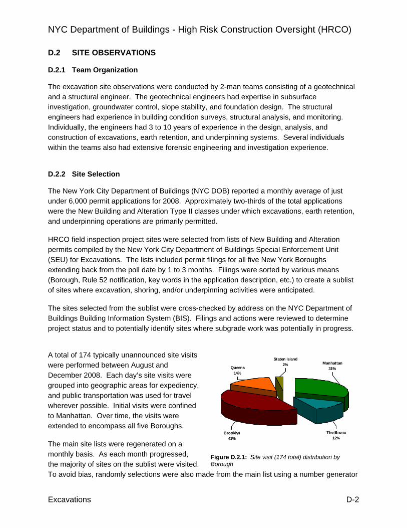
NYC Department of Buildings - High Risk Construction Oversight (HRCO)
Excavations D-2
D.2 SITE OBSERVATIONS D.2.1 Team Organization The excavation site observations were conducted by 2-man teams consisting of a geotechnical and a structural engineer. The geotechnical engineers had expertise in subsurface investigation, groundwater control, slope stability, and foundation design. The structural engineers had experience in building condition surveys, structural analysis, and monitoring. Individually, the engineers had 3 to 10 years of experience in the design, analysis, and construction of excavations, earth retention, and underpinning systems. Several individuals within the teams also had extensive forensic engineering and investigation experience.
D.2.2 Site Selection The New York City Department of Buildings (NYC DOB) reported a monthly average of just under 6,000 permit applications for 2008. Approximately two-thirds of the total applications were the New Building and Alteration Type II classes under which excavations, earth retention, and underpinning operations are primarily permitted.
HRCO field inspection project sites were selected from lists of New Building and Alteration permits compiled by the New York City Department of Buildings Special Enforcement Unit (SEU) for Excavations. The lists included permit filings for all five New York Boroughs extending back from the poll date by 1 to 3 months. Filings were sorted by various means (Borough, Rule 52 notification, key words in the application description, etc.) to create a sublist of sites where excavation, shoring, and/or underpinning activities were anticipated.
The sites selected from the sublist were cross-checked by address on the NYC Department of Buildings Building Information System (BIS). Filings and actions were reviewed to determine project status and to potentially identify sites where subgrade work was potentially in progress.
A total of 174 typically unannounced site visits were performed between August and December 2008. Each day’s site visits were grouped into geographic areas for expediency, and public transportation was used for travel wherever possible. Initial visits were confined to Manhattan. Over time, the visits were extended to encompass all five Boroughs.
The main site lists were regenerated on a monthly basis. As each month progressed, the majority of sites on the sublist were visited. To avoid bias, randomly selections were also made from the main list using a number generator
Figure D.2.1: Site visit (174 total) distribution by Borough
Brooklyn41%
The Bronx12%
Manhattan31%Queens
14%
Staten Island2%

NYC Department of Buildings - High Risk Construction Oversight (HRCO)
Excavations D-3
and the index value site listings. The random process often selected sites where the work duration was expired, or where the indicated activities were of limited or no interest (e.g., shallow excavations with no earth retention or underpinning, interior renovation work, or demolition) to the excavation study. In the few cases where the selection process identified sites that also appeared on the manually sorted sublist, the sites had either already been visited, or were slated for a future visit.
Individual firms were not targeted for site selection. Due to the limited time frame available for the field survey, and the relatively brief duration of excavation, earth retention, and underpinning operations as a portion of the project construction, the site selections were directed toward producing as broad a sampling as possible.
D.2.3 Observation Protocol Upon arrival at a job site, the HRCO teams introduced themselves to the site superintendent, foreman, site safety officer, or other responsible individual for the project construction. The team leader provided a brief explanation of the HRCO effort, explained the purpose of the visit, and requested permission to access the site and conduct an observational survey. The superintendent was informed that the HRCO was conducting an information survey as a consultant to the NYC Department of Buildings. It was made clear that although the HRCO did not have enforcement powers and the purpose of the visit was not the issuance of violations, site observations and construction safety related issues would be reported to the NYC DOB.
Following an initial site assessment and discussion to obtain an overview of the current construction activity, the on-site design drawings related to excavation, earth retention, and underpinning were reviewed in the presence of the site superintendent. The design drawings were compared to the associated architectural and structural drawings where these drawings were also available.
A visual inspection of the site and the exterior of the surrounding structures facing the site was then performed. Completed construction was evaluated for conformance to permitted plans, general workmanship, suitability to the site conditions, and performance. Identified instances of substandard or non-conforming work were brought to the attention of the superintendent. The surrounding buildings were examined for readily visible signs of damage or distress which could be related to recent or on-going construction activities. Upon completion of the project site observations, the adjacent structures were visually surveyed individually. When permission was obtained, the adjacent properties were entered and examined for signs of damage not visible from the exterior, and to assess the extent of damage propagation through the structure. Upon completion of the adjacent property surveys, the HRCO team returned to the project site and discussed the general findings with the superintendent.
In instances where site activities were determined to be immediately endangering workers, the general public, or the stability of adjacent structures, the superintendent was notified of the

NYC Department of Buildings - High Risk Construction Oversight (HRCO)
Excavations D-4
issue and a report was filed with the Emergency Operations Center and the NYC DOB was alerted. Where the construction activities were determined to be proceeding improperly, but the risk to individuals or adjacent structures was not imminent, the Special Enforcement Unit for Excavations was notified and the superintendent was advised that a follow-up site visit by DOB Inspectors should be expected.
D.2.4 Data Collection The field observations were recorded on standardized Location Reports that included sections for general site information, project information, general results, and a series of review categories related to design and construction. The Location Reports were created by the HRCO, in collaboration with the NYC DOB, as a checklist to accumulate raw site data. Existing NYC DOB inspection forms were used as the model for the checklist which was stored electronically. A Location Report was completed for every site visit, to the extent of the available information, regardless of whether or not the contractor was on-site. Access was gained at 76 of the sites visited, which is slightly less than half of the 174 total. The percentage distribution of visits was essentially the same as the total distribution.
Digital photographs were taken of the project site, design drawings, and the adjacent structures. Construction activities related to excavation, earth retention, and underpinning were photographed to document the work being performed. Substandard and superior work was photographed as it was encountered. Readily visible signs of damage or distress observed in adjacent structures was photographed with reference scales (e.g., rulers, crack gauges, pencils, team members) wherever possible.
Notes of observations and conversational interviews with the superintendent, workers, or the site safety officer were recorded in a field book. A general sketch of the project site was made for comparison to site drawings. The relevant observations, sketches, and photographs were compiled into Special Reports which included narrative sections for general site information, site observations, and a summary of the design and construction issues encountered during the information survey.
Figure D.2.2: Accessed site (76 of 174) distribution by Borough
05
1015202530
Manhatt
an
The Bro
nx
Brookly
n
Queens
Staten
Islan
d

NYC Department of Buildings - High Risk Construction Oversight (HRCO)
Excavations D-5
D.3 INVESTIGATION RESULTS To the extent observed by the HRCO, New York City follows the basic US (and majority European) pattern for development wherein several contracted consultants provide designs and analyses that are combined by the project manager to create construction documents. In most cases, the manager will be the project architect or structural engineer, and the consultants will largely work independently within their areas of expertise. On exceptionally significant buildings, or large infrastructure projects it is not uncommon for the major consultants to work as a team, but they are generally provide services under separate contracts. An interesting alternative to the basic design and construction concept is the Australian alliance system in which a consortium of consultants and contractors bid for a project as a single entity. Conceptually similar to the practice of design-build, the alliance system differs in that the design is not fully realized at the time of the bid, and the bid is for the project rather than a specific subcomponent of the construction. Often the alliance is responsible for finalizing the design (including site investigations, structural design, permitting, etc.) and managing the construction.
In New York City, excavations, earth retention, and underpinning systems are designed by a subgrade consultant. The State of New York places no practice area restrictions on professional licenses, and the design may be performed and the drawings stamped by any registered engineer or architect in good standing. The NYC DOB permitting process is fundamentally self-enforcing; submittals are reviewed only for fire, egress, and zoning - none of which apply to excavations, earth retention, or underpinning. The Professional Certification program enables designers to avoid even this cursory review, if their firm has been pre-qualified. The declared subgrade consultant (be it either the geotechnical designer or the engineer or architect signing the TR-1) is responsible for verifying that the contractor is installing the system in accordance with the specifications and requirements of the design, and that the system is performing as intended. The required inspections may be performed personally or by an authorized representative of the designer, or, alternatively, the inspections may be performed by an independent testing firm contracted through the owner or developer.
D.3.1 Design A subgrade consultant was identified at 76 of the inspection sites either directly from design documents or through discussion with the superintendent. The list includes 59 different firms, none of which was encountered on more than 4 separate sites. The diversity of the sample would tend to indicate that the observations were representative of the general state of the local practice rather than an isolated group. Less than 30% of the subgrade consultants had additional involvement with the project beyond the design of excavation, earth retention, and underpinning. The subgrade consultant was the project geotechnical engineer at 9 sites, the structural engineer at 9 sites, and the architect at 3 sites. What this amounts to is that there is a often a separation, and potentially lack of communication, between subgrade consultant doing the design and the geotechnical firm that then provides inspection and testing services during construction.

NYC Department of Buildings - High Risk Construction Oversight (HRCO)
Excavations D-6
However, the relatively low cross-over rate of geotechnical engineers is likely somewhat misleading. Although some firms intentionally limit their practices to site investigation and evaluation, the design and analysis of excavations, earth retention, and underpinning are traditionally geotechnical fields. With a few exceptions, geotechnical reports were not available on-site, and in most cases boring logs or other test data which could help identify the project geotechnical engineer was not included in the either the structural or architectural drawings. Unlike architects, structural engineers, and contractors, geotechnical firms are not routinely listed on project drawing title blocks. Thus, there may actually be a greater percentage of geotechnical firms that are also conducting design work, than implied by this study.
Somewhat surprisingly, general contractors were often at a loss when asked to provide the name of the firm which performed the subsurface investigation. Although the geotechnical work would in most cases be completed in advance of the engagement of the general contractor, it is expected that the information and recommendations contained in the report would be distributed as part of the project documents. As a minimum, subgrade contractors typically maintain a copy of the boring logs as a reference for indications of potential driving obstructions, unusual or significant variations in soil conditions, and groundwater fluctuations, but this does not appear to be a standard practice in New York City.
The submission of calculations and analyses is not a standard requirement for permitting excavations, earth retention, or underpinning in New York City. Consequently, the basis of design could only be inferred from the content of approved permit drawings encountered in the field. In general, the designs appeared to be conventional and tailored to the planned depth of cut rather than site conditions. The near surface soils of New York City can geologically be classified as glacial drift, morainal piles, alluvial beaches and dunes, and in most areas the natural deposits are topped by layer of urban fill. The majority of the soils encountered in typical excavations of less than about 15 feet would be expected to be predominantly granular, although clay beds may be encountered in near coastal areas. The relative uniformity of the soil conditions contributes to the homogeneity of design across the five Boroughs.
A 1:1 (horizontal to vertical) cut slope is used for excavations almost by default in New York City. Little, if any, consideration appears to be given to the stability of the cut slope regardless of the excavation depth or subsurface soil conditions. On Staten Island, uniform cut slopes were replaced by benched excavations at two of the sites visited by the HRCO. However, in both cases the overall slope of the excavation was not flatter than 1:1.
Soldier pile and lagging is the most widespread earth retention system currently in use in New York City. Driven or pushed steel sheet pile designs and/or components were not encountered at any of the sites visited by the HRCO. Internal bracing to a deadman is utilized (presumably) to reduce the embedment and required section modulus of the soldier piles without regard to the complexities the system creates for installation. Even for relatively small cuts of less than 8 feet, braced systems are more prevalent than cantilever systems. Of the earth retention systems rated inadequate during the HRCO survey, nearly 50% had design embedment to

NYC Department of Buildings - High Risk Construction Oversight (HRCO)
Excavations D-7
unbraced height of cut ratios that were considered too small for the indicated pile spacing (assuming general soil properties and a nominal factor of safety). At a site in the Bronx, a soldier pile length of 15 feet was specified on the design drawings for an excavation of 15 feet. Insufficient embedment is often an indication that the retention system was designed for lateral forces only (as shoring would be) rather than bending of the soldier piles. No integrated systems that combine earth retention and permanent foundation or perimeter wall support were encountered in the site inspections.
Underpinning almost exclusively consists of conventional hand-dug pits. Only a single case of an alternative system (micropile support of the building foundation combined with shotcrete and soil nails for earth retention) was encountered during the site inspections. Lower-risk, modern underpinning systems are generally dismissed as too expensive or, more likely, not considered at all out of habit or a lack of familiarity with their application. Because embedment of the underpinning does not generally extend more than a few inches below the level of the proposed excavation, it can reasonably be surmised that the terminal depth of the underpinning is almost certainly based on the desired depth of cut, and not on the suitability of the bearing soil to support the foundation loads. In principle, underpinning in New York City appears to be viewed more as a means of earth retention rather than as supplemental or replacement foundation support.
Consisting as it does of islands and coastal plains, the design of excavations and earth retention systems in New York City would be expected to be dominated by groundwater considerations. Improper design for groundwater is generally acknowledged as the leading cause of excavation instability and the failure of earth retention systems. However, the bedrock spine of Manhattan and the accumulation of the drift and outwash soils have resulted in a topography that enables excavations for buildings with single level basements to be performed above the groundwater table. Localized areas of higher groundwater do occur in low-lying kettles, the natural lowland valleys of northern Manhattan and the Bronx, and in near shore areas subject to tidal fluctuations, but for the most part excavations are performed in the dry. An active groundwater extraction system was observed at only one site during the survey.
D.3.2 Methods of Construction Ninety seven general contractors and 49 different subgrade contractors were identified at the sites visited by the HRCO. The general contractor was also identified as the subgrade contractor at only 6 sites.
The quality of workmanship related to the advancement of excavations, and the construction of earth retention and underpinning systems in New York City is fair to average. Some exceptional formwork and welding was observed at several sites, but at least an equal number of occasions of substandard work was also noted during the site visits. Of the sites where readily visible deficiencies were identified, issues with soldier pile layout accounted for 35% of the retention systems inadequacies. Violation of the design sequencing was noted twice as often (44% of

NYC Department of Buildings - High Risk Construction Oversight (HRCO)
Excavations D-8
identified deficiencies) as any other underpinning inadequacy. Construction variations from permitted drawings and undocumented field changes were observed at 25 to 30% of the sites where earth retention and underpinning was either in progress or complete at the time of the HRCO visit. At a site in Brooklyn where the design drawings indicated the need for 3 feet of underpinning, the contractor was installing pins beneath the building to a depth of 8 feet.
According to the site superintendents, more field changes result from unanticipated high bedrock than any other site condition. The local level at which bedrock is located can drastically affect excavations and the construction of earth retention systems, yet it is often poorly defined in site investigations. Gratacap (1909) and Schuberth (1968) have extensively documented the geology of New York and it surroundings. In gross general terms, the bedrock in Manhattan is located about 40 feet below grade at the southern tip of the island, outcrops in the center, and dips dramatically in the north to more than a hundred feet below grade. The mica schist of the Manhattan formation which is the youngest rock of the New York City group has a southwest plunge, and it falls off from the island fairly dramatically. It resurfaces in outcrops at Governors Island but is well below the surface under Staten Island, Queens, and Kings counties. Up-thrusting Fordham gneiss is exposed in the western part of Bronx County and a few outcrops occur in Long Island City.
Subsurface investigations are performed to define geotechnical engineering parameters and develop recommendations for the design and construction of foundations and earthwork for the proposed structure. For reasons of cost the scope is primarily limited to defining the most prevalent subsurface soil, rock, and groundwater conditions that can reasonably be expected to be encountered within the footprint of the planned structure. Access limitations due to existing structures within and adjacent to the site, and practical considerations on the quantity of soil borings, can result in larger separation distances between the boring locations on the site perimeter than those on the interior. As the distance between borings increases the validity of straight-line interpretation of the subsurface conditions inevitably decreases.
The bedrock surface is by no means uniform across Manhattan, and even within relatively small lateral distances the variations can be significant. Folds, intrusions, eroded zones, pinnacles, all contribute to an erratic profile that belies the oversimplification of a general east to west dip of the bedrock formations. At a Midtown site visited by the HRCO, where significant rock excavation was anticipated across the entire footprint of the planned structure, the bedrock surface exposed during excavation was found to vary by at least 20 feet from west to east, and the slope was even more significant in the north to south direction. In the southeast portion of the site, the surface was found to have fallen off so sharply that the bedrock actually dropped well below the maximum planned excavation depth, and an existing multistory building with a basement assumed to be on, or within a few feet of bedrock, had to be underpinned by 10 to 15 feet along its entire length.
Even when well below the planned maximum depth of excavation, the variations in the bedrock surface can still have a considerable effect on site operations. The passive resistance of soldier

NYC Department of Buildings - High Risk Construction Oversight (HRCO)
Excavations D-9
piles is developed below the bottom of the cut, and properly designed earth retention systems have a specified minimum length of embedment. If the required embedment is not provided in construction, and no other corrective measures are taken, the wall will not have the factor of safety in service it was designed for.
Soldier piles in New York are almost universally installed by driving with vibratory hammers. No impact hammers were observed at any of the HRCO site visits. Where obstructions are encountered, piles are over-driven well beyond the point of damage. Rather than drilling, piles that cannot reach design depth because of shallow rock are supplemented with toe pins installed when the excavation reaches the rock interface. Alternatively at several sites, soldier piles were replaced entirely by cast-in-place concrete piers constructed using shored box pits to avoid drilling into rock.
At a site in Manhattan, soldier piles were driven through an abandoned concrete box sewer, and over-driven at the top of rock so significantly that an estimated 60 to 70% were buckled, twisted, out of alignment, or had major flange damage that prohibited the standard installation of lagging. The initial geotechnical investigation reportedly had indicated that sufficient depth of soil was available for the soldier pile embedment. The bedrock surface exposed in the excavation was highly variable, particularly at the perimeter of the site, and it is unlikely that a limited investigation could have identified the undulations on a spacing equivalent to that of the soldier piles. It is surprising, however, that despite the difficulties encountered, the contractor continued to attempt to drive the piles to the design tip elevation. Once it was determined that shallow rock was present, the designer should have developed an alternative solution, preferably in concert with the contractor, to deal with the revised site condition. While the demarcation between soil and rock is not as observationally distinct when piles are driven with a vibratory rather than an impact hammer, the lack of penetration and the butt end damage should have been readily visible when the piles reached refusal. The inspector or the crew foreman should have stopped driving as soon as possible after refusal to reduce damage to the piles and, more importantly from the contractor’s perspective, to the hammer. The extent of the piles damaged during installation is indicative of insufficient oversight, poor communication, and inexperience on the part of the field personnel and the inspector.
In addition to the bedrock variation, contractors indicated that the subsurface soils in the underpinning excavations were often found to contain a significantly greater proportion of cobbles and boulders than would be indicated by the borings. To some extent this should hardly be surprising as most of the sites had been previously developed. The borings performed for the new structure would almost certainly have been located in disturbed regions that would not necessarily be representative of the (presumably) natural soils at an equivalent elevation beneath the shallow footings of adjacent structures.
Hand-dug underpinning work in New York City is typically done by small general excavation contractors, although a few specialized firms do exist. Contractors prefer to insert pre-assembled boxes for shoring underpinning rather than installing individual boards as the

NYC Department of Buildings - High Risk Construction Oversight (HRCO)
Excavations D-10
excavation proceeds (as would be done for a soldier pile and timber lagging wall), and a 3 to 4.5-foot deep, block excavation with vertical sidewalls is common. Arching, stand-time, and “hard” soil – along with anecdotal experience – are usually claimed as the rationale for the practice.
Although not entirely correct, the contractors’ argument is not without merit. While still predominantly granular, many of the soils exposed in the underpinning excavations at the sites visited by the HRCO appeared to contain an appreciable amount of silt and clay which would help to retain moisture. At the face of an excavation there will be some dilation and a localized reduction in the pore water pressure. In unsaturated soils the pore water pressure can actually become negative which increases the soil strength, and allows even sands to stand vertically for a short period of time. The effect, however, is temporary, and as the soils dry, this “apparent cohesion” disappears and the excavation sidewalls will begin to spall. In this way, much of the New York City subsoils can be said to be fairly well-suited to small short-term excavations, and it is likely a contributing factor to the dominance of hand-dug underpinning.
Incomplete definition of foundations for surrounding structures is a significant issue for underpinning, and too often contractors must rely on their own judgment to estimate the bearing level. While most experienced contractors can easily make an estimate within at least a few feet of the bearing level - based on structure size, evidence of a basement, or their local knowledge about the type and age of construction - their judgment should not be expected to compensate for an inadequate preconstruction survey.
D.3.3. Performance The short-term stability of the soils in New York City, while beneficial to underpinning, has likely contributed to a sense of over-confidence in the performance of excavations, earth retention, and underpinning. Designers may become complacent and may not fully evaluate the suitability of the proposed system to the local conditions. Contractors can often wrongly correlate success at one site to expertise, and then apply those construction methods universally in their operations without giving regard to project variables.
Unfortunately for adjacent property owners, there is a tendency for those involved in design and construction to concentrate on the project site without paying commensurate attention to surrounding structures. This is a well known issue in most major US cities, and there is no indication that architects, engineers, or contractors practicing in New York City are any more prone to defining their responsibilities by the project property lines than their counterparts elsewhere. The incidence of disassociation was not tracked by the HRCO, and it is questionable, given the subjective interpretation required, whether any such data would be meaningful. It is perhaps sufficient to be aware that most projects are not conceived with the best interests of the adjacent owners as a primary concern.
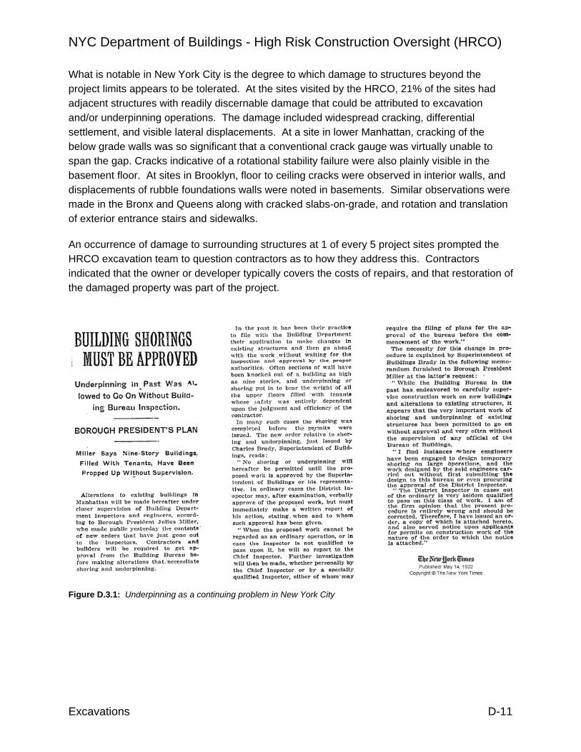
NYC Department of Buildings - High Risk Construction Oversight (HRCO)
Excavations D-11
What is notable in New York City is the degree to which damage to structures beyond the project limits appears to be tolerated. At the sites visited by the HRCO, 21% of the sites had adjacent structures with readily discernable damage that could be attributed to excavation and/or underpinning operations. The damage included widespread cracking, differential settlement, and visible lateral displacements. At a site in lower Manhattan, cracking of the below grade walls was so significant that a conventional crack gauge was virtually unable to span the gap. Cracks indicative of a rotational stability failure were also plainly visible in the basement floor. At sites in Brooklyn, floor to ceiling cracks were observed in interior walls, and displacements of rubble foundations walls were noted in basements. Similar observations were made in the Bronx and Queens along with cracked slabs-on-grade, and rotation and translation of exterior entrance stairs and sidewalks.
An occurrence of damage to surrounding structures at 1 of every 5 project sites prompted the HRCO excavation team to question contractors as to how they address this. Contractors indicated that the owner or developer typically covers the costs of repairs, and that restoration of the damaged property was part of the project.
Figure D.3.1: Underpinning as a continuing problem in New York City

NYC Department of Buildings - High Risk Construction Oversight (HRCO)
Excavations D-12
Given the rate of damage, a heightened sensitivity to construction monitoring would be expected. Within the confines of Manhattan only approximately 65% of the sites visited by the HRCO either had a system in place for monitoring the surrounding structures, or planned to install one in advance of the start of excavation or underpinning. In the remaining four Boroughs less than 18% of the sites visited had monitoring programs in place or planned to install one. Of the few sites in the outer Boroughs that did have monitoring, nearly one-half of them were adjacent to a MTA structure and the program was instituted at their direction.
Contractors in the Boroughs most commonly reported performing vibration monitoring during soldier pile driving. Vertical and lateral survey monitoring was reported second most often. Surprisingly, the number of contractors that reported that no monitoring had been, or would be, performed was twice as large as the number that reported it had been performed.
Whether because owners will not pay for the services, designers are not diligent, or contractors fail to notify, inspection of earth retention and underpinning construction was rated by the HRCO as poor throughout New York City. Cost and contractual issues aside, poor coordination and communication among designers, designated inspectors, and contractors appears to be the major contributing factor. When asked, 35% of the contractors could not identify the special inspector at the sites visited by the HRCO. Based on the field observations, the qualifications and experience of special inspectors was rated fair to poor. Construction deficiencies which should have been readily discernable (and for the most part correctible) to an inspector with average training and construction experience were observed at 36% of the sites with earth retention systems, and at 26% of the sites with underpinning. Omitted welds, inappropriate connections, substitution of materials, improper excavation and stockpiling, inadequate shoring of approach pit sidewalls, to name just a few of the most common observations, were widespread throughout New York City.
Perhaps no observed omission was as critical, and fundamental, as the lack of construction staging in design and construction. Less than 10% of the permitted earth retention system designs at the sites visited by the HRCO defined staging (including excavation limits, order of assembly, prestressing requirements, installation of deadman, connection of rakers, etc.) for the construction. Virtually none of the drawing sets, including those which had been formally reviewed by the MTA, included cross sections for intermediate stages of construction. In almost all cases, only the final condition was shown, regardless of the number of levels of bracing or the depth of excavation. Earth retention systems must be analyzed for all construction stages to
Figure D.3.2: Observed monitoring systems in New York City
0
510
15
2025
30
Surv
ey
Vibr
atio
n
Tiltm
eter
s
Cra
ckG
auge
Non
e
BoroughsManhattan

NYC Department of Buildings - High Risk Construction Oversight (HRCO)
Excavations D-13
verify the components are adequately sized, and to verify that the ground movements will be within the desired tolerances. Essentially every braced system will have an initial cantilever stage. Tieback and bracing loads will vary as the excavation is advanced, and the design must consider each stage to define the range of performance and the maximum capacity required.
With no clear instructions, the inexperience of some contractors inevitably creates construction hazards as they attempt to define their own “means and methods”. At a site in Brooklyn a contractor attempted to install a cast-in-place concrete deadman for a braced earth retention system by advancing an unshored excavation 15 to 18 feet from existing site grade. The sidewalls were nearly vertical, and excavated material was stockpiled adjacent to the excavation. A worker was lowered into the excavation on the bucket of a backhoe to set a pre-assembled concrete form in the presence of the HRCO. A simple staging outline, that provided an intermediate excavation depth to attach a waler, nominal dimensions for an unexcavated perimeter berm, an interior excavation to install deadmen, and a bracing connection followed by final berm excavation should have provided (and each stage should have been checked) to prevent just such an occurrence.
Individually the design flaws, incidences of damage, and lax oversight are certainly causes for concern. When considered as a whole, they point to the somewhat inescapable conclusion that there are design professionals and contractors in New York City practicing outside their areas of expertise. The percentage is by no means a majority, and most of the professionals and contractors are conscientious and diligent in their work. However, unfamiliarity with proper pre-design site investigation requirements, inexperience with analysis methods, a lack of understanding of construction operations, and a general un-preparedness for readily foreseeable construction difficulties was all too often evident at the sites visited by the HRCO.
Excavations, earth retention, and underpinning are highly specialized practices. The design of these systems requires expertise in geotechnical and structural engineering. Construction of many of the systems involves the use of specialized equipment with dedicated and trained crews. Knowledge about the effect of the construction on the surroundings is critical for both design and construction. In some states regulators have attempted to restrain operations by requiring what is conceived as a “higher degree” of certification. In Illinois an engineer must be licensed as a structural engineer, as opposed to a professional engineer, to stamp drawings that involve earth retention or underpinning. In addition to professional engineers, California offers licenses for geotechnical, and structural engineers each with differing requirements and limitations on their application. Several states utilize some form of licensing or certification to define suitable subgrade contractors for DOT or other government funded contracts. The enactment of any similar changes for New York would require legislation at the state level.

NYC Department of Buildings - High Risk Construction Oversight (HRCO)
Excavations D-14
D.4 DOB PROCESS REVIEW The HRCO excavation team reviewed DOB operations as a part of this study, focusing on operations of the Special Enforcement Unit (SEU). The review included mapping of the SEU operation, accumulation of field guidance documents and checklists used by inspectors and engineers, as well as observation of the inspectors and engineers during the performance of their duties. The SEU audit process was audited itself, through review of archive job files by HRCO engineers. The HRCO visited 25 sites in conjunction with DOB inspectors. Observations were made in the areas of technical expertise, interaction with contractors, knowledge of construction site operations, and the standard methods employed in the performance of the duties of the inspectors. The HRCO also reviewed 35 SEU audit files. The reviews assessed the effectiveness and completeness of the audits. These DOB process reviews are reflected in the recommendations in this report, such as the need for differentiation in underpinning permitting, advance notification of underpinning operations and proactive plan review. The process reviews also resulted identification of initiatives that the DOB could consider to improve performance in site inspections and file audits.

NYC Department of Buildings - High Risk Construction Oversight (HRCO)
Excavations D-15
D.5 EXISTING REFERENCE REGULATION Because of the dense packing of structures in New York City, virtually all construction projects will have an affect on, or be influenced by, buildings and facilities beyond the project property lines. New York is not the first city to grapple with balancing the rights of owners against the protection of adjacent properties.
By the start of the 19th Century, London had a population slightly in excess of a million souls. By 1851, nearly 2.4 million people occupied a space of 90 square miles. For better or worse, London was the first post-industrial revolution experiment in social management, civic infrastructure, and community planning. The lessons learned from the local London Building Acts inspired the British Party Wall Act which was enacted in 1996 for application throughout England and Wales.
On the Continent, the Deutsches Institut für Normung e. V., or DIN, has published national construction standards for application throughout Germany since 1947. DIN participates directly in European standardization. It is fundamentally involved in the process of drafting new European standards (designated as DIN EN), and devotes much of its time and resources to continually updating and reviewing existing national construction standards. Originally published in 1972, DIN 4123 which specifies provisions for excavation and foundation work adjacent to existing buildings, was revised in 2000, and a 2008 draft is currently in review.
Separately, these two documents are excellent examples of thoughtful, practical regulation. Combined, they form the basis of basis upon which an organized approach to managing excavations, earth retention and underpinning can be modeled in New York City.
D.5.1 British Party Wall Act The clearest example of the shared interest of neighboring properties is the common party wall. In its simplest definition a party wall is any wall that is located on a property line between parcels of land belonging to at least two different owners. A party wall can be an exclusive part of one building, separate two or more buildings, or it could act as a separation fence. A masonry garden wall which is supported on a foundation could be a party wall depending upon its height, but wooden privacy fences are not typically considered party walls. A wall located within a single property can also be a party wall if it is used by two or more owners to separate their buildings. Such a situation can occur when a new structure is located immediately adjacent to an existing building wall and the new building did not construct their own wall.
When flats, rowhomes, and similar buildings share an integral structural component such as a wall or floor partition that also acts a separation between buildings or parts of buildings, a broader term of party structure is typically applied. In a looser interpretation, the term party structure can also be applied to situations where the stability of separate buildings is reliant upon the structural integrity of the adjacent structure. An excellent example of this type of

NYC Department of Buildings - High Risk Construction Oversight (HRCO)
Excavations D-16
construction are the surviving late 19th Century-era mercantile buildings that are sprinkled across Lower Manhattan. When examined individually, many of these structures do not have sufficient lateral resistance capacity to be inherently stable (in terms of modern methods of design and analysis) for their constructed heights. Rather than acting as free-standing structures, the buildings naturally “lean” into each other, and the mass of the pair works together to provide lateral stability.
The impact of construction is not limited to immediately adjacent or adjoining structures. Structures that are set back from the property line can be affected if some portion of their foundation support is derived from the soils within the active zone of an excavation. In geomechanics the active zone of a soil mass is expressed using the Mohr-Coulomb failure envelope which is defined by the shear strength. Because shear strength varies with soil type, the active zone is conservatively generalized to encompass the block of soil above a 45 degree line projected from the base of the excavation. Conventionally, the region which represents the area of soil which may move as a result of the excavation is termed the zone of influence.
The shared interest of party walls, party structures, and the zone of influence imposes an obligation on any owner that wishes to make improvements to, or substantially alter, his property to protect adjacent structures from damage that may result as a consequence of the construction. While an owner has the right to make improvements within the limits of zoning for his own property, the developer’s rights do not supersede those of surrounding property owners or in any way entitle the owner to access or perform work on an adjacent, or influenced, structure without the consent of the respective owners.
In an effort to provide a mechanism to prevent and resolve the inevitable conflicts and disputes that result between adjacent owners, the British Parliament enacted the Party Wall etc. Act in July 1996. Under the Act, anyone intending to carry out work that involves a shared interest (e.g., direct work on a party wall, new construction at a property line, or excavations within a defined distance of an existing building) must give the affected owners notice of their intentions. Adjoining owners can agree with the developer’s proposals or negotiate changes in the timing and/or manner which the construction operations will be carried out. The developer is required to provide temporary protection for adjacent buildings and property where necessary. In the event that an adjacent property is damaged by the construction, the developer is responsible for making good through repairs or direct compensation.
With consent the adjoining owner agrees to provide access for the developer’s engineer or architect, workers, etc., to carry out any necessary inspections, evaluations, and eventually the planned construction. If an agreement cannot be reached, or the adjoining owner has not responded after a period of 14 days from the service of the notice, the construction is classified as being in dispute. The Act requires that an independent peer engineer or architect be engaged to arbitrate the dispute. The peer is required to prepare a "party wall award" which:
• describes the scope of work that will be carried out,

NYC Department of Buildings - High Risk Construction Oversight (HRCO)
Excavations D-17
• provides apportionment of costs for the work (if the benefits are shared, or if the work includes repairs associated with inadequate maintenance by the affected owner),
• defines the operational time limits within which work may be performed, • specifies any additional work required (including supplemental condition surveys,
baseline establishment for monitoring, and the design and construction of systems to prevent or mitigate potential damage), and
• allows access for engineers from both sides to inspect active construction. The determination of the peer is expected to be impartial, and it is binding unless altered by legal action.
The British Party Wall Act was intended to be a framework for resolution of disputes. The general principle of the Act is accommodation through advance notification and fair and honest negotiation. There are no enforcement procedures for failure to serve a notice. However, if work is initiated without proper notice, adjoining owners may seek to stop construction through a court injunction or seek other legal redress. Adjoining owners cannot stop a property owner from exercising the right to develop or perform improvements, but under the Act they may be able to influence how and at what times the work is done.
It is important to note that reaching agreement with the adjoining owners under the Act does not relieve the developer from an obligation to comply with building regulations procedures. It should also be recognized that the corollary situation of compliance with building regulations and the issuance of an approved permit does not release the developer from the need to comply with the Act.
More recently in 2008, the District of Columbia adopted Section 3307A for the protection of adjoining property as a supplement to their building code. Fundamentally similar to the British Party Wall Act, the D.C. supplement requires written notification to be provided to the affected property of the need for protective work in association with the planned construction. The affected owner has the option to grant permission for access, perform the necessary protective work themselves (for which they are granted access as required to the construction site) in an expeditious manner that will not impede construction, or affirmatively deny permission. The denial must be accompanied by a justification to the code official indicating the reason for the refusal.
Where the D.C. provision diverges from the British Party Wall Act is in the case of existing adjoining or party walls which require underpinning. Rather than advocating an arbitration, Section 3307A requires the person causing the work to provide proper underpinning for the structure whether or not written permission to enter the adjoining lot is granted. Although the underpinning for this specific exception can be performed without the permission of adjacent property owner, it does not relieve the developer of the obligation to provide proper notification.

NYC Department of Buildings - High Risk Construction Oversight (HRCO)
Excavations D-18
D.5.2 DIN 4123 The German standard is limited to simple cases of vertically loaded strip and wall foundations. It is intended to address buildings under 5 stories with foundation loads less than about 17 kip/ft that are underpinned using classical methods.
In a short and succinct document, DIN 4123 defines the requirements for documentation, site management, planning, site investigations, and stability analyses which must be completed in advance of construction. The standard defines excavation limits and general foundation provisions for the new structure, and it describes the acceptable methods and limitations of underpinning construction.
Throughout the document the need for monitoring of the structure being underpinned is stressed. The stated purpose of the standard is to describe the procedures which will be allowed, and the checks and analyses which must be made, so as minimize the risk to the stability and serviceability of the existing building.
NYC Department of Buildings - High Risk Construction Oversight (HRCO)
Excavations D-19
D.6 SUMMARY OF RECOMMENDATIONS The nine recommendations individually address specific topics which, based on HRCO field observations and the industry outreach, would be expected to have the most immediate effect on improving safety through design, construction, inspection, and regulatory oversight. Each recommendation consists of a summary statement of the recommendation, a description of the issue and primary supporting information, considerations for implementing the recommendation and, in some cases, additional observations associated with the recommendation. Additional benchmarking observations are summarized in the Benchmarking chapter of this report, that were not available for this chapter, due to timing of preparation of this report.
The recommendations are summarized below:
Excavations at Footings (E-1)
Excavations which must extend below the bearing level of an existing footing or foundation should be restricted to ensure adequate measures are taken regarding stability of the structure.
Permitting of Underpinning (E-2)
DOB should implement a procedural method for permitting underpinning that is differentiated as shallow or deep to better screen these operations for associated safety issues.
Preconstruction Surveys (E-3)
DOB should provide minimum requirements for a preconstruction survey that defines the baseline condition of adjacent and influenced structures on, and surrounding, a project site. A professional engineer should be responsible for submitting the survey.
Monitoring During Excavations (E-4)
The excavation, earth retention system, or underpinning designer should identify all influenced structures, and should establish a monitoring program for the construction operation, meeting minimum requirements established by DOB.
Minimum Drawing Standards (E-5)
Design submittals for excavation, earth retention, or underpinning permits should include sufficient plan, section, and detail drawings as necessary to convey the full intent and scope of the construction. DOB should establish minimum requirements for submittals.

NYC Department of Buildings - High Risk Construction Oversight (HRCO)
Excavations D-20
Limited Technical Review (E-6)
Require pre-permit technical review of excavation, earth retention system, and underpinning permit designs.
Underpinning Notification (E-7)
The contractor should notify the Department of Buildings a minimum of 24 hours, but no more than 72 hours (3 working days) in advance of the start of underpinning construction. The notification should be written, and it should include a brief narrative description of the activity including the length and location of underpinning to be installed, height of typical pit or pier, and the estimated duration of construction. The contractor should also be required to provide the same notification to the underpinning designer and to the responsible agent for special inspections if different from the designer.
TR1 and Inspection Log (E-8)
Critical inspection information, including the TR1 form and a log of special and progress inspections should be maintained on site for the benefit of the construction parties and DOB.
On-Site Meeting (E-9)
The contractor should schedule an on-site meeting with the designer and special inspector (as applicable) to walk through the planned operation in advance of the start of construction. The contractor should the notify the Department of Buildings of the time and place of the meeting, and attendance by the NYC DOB should be at their discretion.
The HRCO excavation recommendations are best considered as a whole. For example, TR1 and Inspection Log provides mechanisms to document, amongst other things, special and progress inspections. The On-Site Meeting recommendation is tied to this in that it provides for an opportunity for the designer to address the issue of how many inspections are appropriate. On-Site Meeting also provides an opportunity for review of sensitive surrounding structures which is relevant to Limitations on Underpinning, Preconstruction Surveys and Monitoring During Excavations. Minimum Drawing Standards is clearly essential to Limited Technical Review, but is also associated with Permitting of Underpinning and Excavation at Footings. Permitting of Underpinning, in turn, particularly as it applies to shallow underpinning, identifies the need for proper Preconstruction Surveys, On-site Meetings and construction inspections (as documented by an Inspection Log) to prevent accidents. Finally, Preconstruction Surveys, Monitoring During Excavations and On-site Meetings work together to address the issue of the large number of older, historic or potentially fragile structures that often immediately border

NYC Department of Buildings - High Risk Construction Oversight (HRCO)
Excavations D-21
excavation operations. Special care must be taken to identify, assess and protect these structures from being compromised by neighboring excavations.
While they were conceived independently, the HRCO recommendations parallel many of the provisions of the German standard DIN 4123. The major design and construction issues related to excavations, earth retention, and underpinning are not exclusive to New York City, and it is not surprising that the gaps identified by the HRCO were encountered in other practices. Several of the HRCO recommendations can be seen to be interrelated, and when considered as a whole, the fundamentals of a standard similar to DIN 4123 can readily be seen.
NYC Department of Buildings - High Risk Construction Oversight (HRCO)
Excavations D-22
D.7 RECOMMENDATION E-1: EXCAVATIONS AT FOOTINGS
Excavations which must extend below the bearing level of an existing footing or foundation should be restricted to ensure adequate measures are taken regarding stability of the structure.
Description An offset of excavations which must extend below the bearing level of an existing footing foundation is standard geotechnical engineering practice. Excavations are typically offset laterally from the edge of the footing a nominal distance of 2 to 5 feet. If the offset cannot be provided, the footing is underpinned, shored, or tied back to restrain lateral movement.
The 1968 and the new 2008 NYC Building Codes do not provide clear requirements for temporary excavations at footings. It is recommended that language be added to restrict the excavations to a defined geometry unless stability is ensured by other means.
The recommendation is specifically intended to improve geotechnical stability for short-term construction operations. The evaluation of the structural integrity of the existing structure is beyond the scope of this recommendation. The recommendation is not intended to relieve the person responsible for making the excavation of the obligation (as required by code) to verify that the condition of the structure is sound enough that the work can safely be performed. Although the excavation is expected to be advanced wholly within the property line limits of the project development, the construction can have an effect on the surrounding structures. The safeguarding of the surrounding structures and facilities is the responsibility of the designer and the person making the excavation.
Examples of situations where this situation may be encountered:
1. Elevator, sump, or mechanical pits located near property lines, 2. New shallow foundations installed close to a vintage structure where the foundations do
not extend to the current frost-depth requirement, 3. New double-depth basement close to, but not immediately adjacent to, an existing
single-level basement. Currently in New York, an excavation at a bearing wall on the property line can extend vertically to the base of the wall (bearing elevation) and then immediately slope downwards at a 1:1 (45 degree) angle. The bearing soils can be left exposed to the elements and are subject to washout, spalling, raveling, wind erosion, etc. There is a risk of sudden rotational failure of foundations left in this condition for an extended period of time.
The typical construction in New York City, particularly in Manhattan, extends from property line to property line. Perimeter walls and foundations are often constructed immediately adjacent to existing structures to maximize building floor plans. In cases where the existing structures are

NYC Department of Buildings - High Risk Construction Oversight (HRCO)
Excavations D-23
located on the property line, and the new building includes a deeper basement, underpinning is commonly utilized if the permission of the adjacent owner can be obtained. In cases where the existing structure is set slightly back from the property line, or where the new building does not extend to the property line – such as rear yards, open cut (i.e., angle of repose) excavations are preferred for cost reasons.
The injury to report ratio for excavations in the 2004 to 2008 NYC DOB incident database provided to the HRCO was approximately 15%. No fatalities were directly identified as excavation related although at least one death was attributed to trenching.
In the March 2007 Regulatory Review of 29 CFR 1926, Subpart P: Excavations, OSHA reported that the annual number of trenching and excavation fatalities declined from an estimated 90 fatalities per year prior to 1989 (nationally), to about 70 per year since 1990. For the eleven year period from 1990 through 2000, the actual number of fatalities each year varied within the range of 59-81. The 22% reduction in fatalities occurred during a 20% real increase in construction activity over the same period. The fatality data was drawn from OSHA's Integrated Management Information System (IMIS) database which tracks data on a national level and by individual industries and causes.
An open cut excavation at a footing was encountered by the HRCO at on site in Manhattan, and the project was still in demolition at the time.
Design drawings depicting the practice were encountered in field reviews, and audit checks of NYC DOB Special Enforcement Unit for Excavations (SEU) job files. In two of the SEU audit checks where the depicted cut slope was specified as 45 degrees or as a 1:1 slope, the SEU engineer failed to identify that the actual excavation slope based on the provided dimensions was steeper.
In the majority of cases reviewed, the small open cut excavations necessary for construction were not designed. The means and methods were left to the discretion of the excavation contractor.
Figure D.7.1: Distribution of fatalities by cause of death (reproduced from OSHA Regulatory Review of 29 CFR 1926, Subpart P: Excavations)

NYC Department of Buildings - High Risk Construction Oversight (HRCO)
Excavations D-24
Recommendation Approach Unless stability and adequate bearing capacity is demonstrated through calculation by a professional engineer, excavations should not extend deeper than the bearing level of an existing footing or foundation within a lateral distance equal to the intended depth of the excavation below the footing or foundation. The provided lateral distance should be measured from the outermost projection of the existing footing or foundation into the area of excavation. The slope of excavation (face of the provided berm) beyond the lateral distance should be no steeper than 1:1 (horizontal: vertical) regardless of soil type. The top of the berm should be at least 18 inches above the bearing level of the footing.
Exception: The stability of any excavation which extends more than 5 feet below the top of the berm (3.5 feet below footing bearing level), or below the normal static groundwater table as determined by on-site measurement, must be demonstrated through calculation by a professional engineer. If the lateral distance cannot be provided, the footing or foundation should be underpinned, or the excavation should be supported by an earth retention system capable of protecting the foundation against settlement and lateral translation. The underpinning or earth retention system should be designed by a professional engineer.
Ideally, all excavations should be designed by a professional engineer. This recommendation approach is intended to provide an absolute minimum, as a guide to DOB plan reviewers. The excavation designer, if specifying anything less restrictive than this, would need to provide engineering justification for the design. As with any excavation, the design considerations should include, but not be limited to:
1. The depth of the excavation, 2. The effect of the removal of the soil overburden on the allowable bearing capacity of the
foundation soil, 3. The unbalanced soil load on the foundation, 4. The groundwater level and effect of any localized pumping or dewatering, 5. The structural integrity and stability of the existing foundation, 6. The foundation loading (eccentricity, surcharge, temporary loads imposed by
construction, etc.).
Figure D.7.2: Limits for excavations less than 5 feet

NYC Department of Buildings - High Risk Construction Oversight (HRCO)
Excavations D-25
Additional Data The Organizational Health and Safety Administration (OSHA) defines nominal cut slopes for depths of excavation greater than 5 feet. The slopes are based on soil type, but do not consider the effects of surcharges or groundwater. The requirements for sloping and benching are defined in 29 CFR, 1926 Subpart P: Excavations, which was revised in 1989. The shallowest slope allowed in granular materials such as gravel, sand, and loamy sand is 1.5:1 (or 34 degrees). The maximum height of cut for a simple slope excavation is 20 feet.
OSHA states that the person causing the excavation must evaluate the site conditions and provide any support systems, such as shoring, bracing, or underpinning, as may be necessary to ensure the stability of adjacent structures during the time the excavation will remain open. Excavation below the level of a base or footing of any foundation or retaining wall is prohibited unless a support system, such as underpinning, is provided; the excavation is in stable rock; or a registered engineer determines that the structure is sufficiently removed from the excavation and the excavation will not pose a hazard to employees. The standard prohibits excavations under sidewalks unless an appropriately designed support system is provided.
OSHA tracked excavation fatalities resulting from a variety of accident types. For the period from 1990 to 2000 approximately one-half of the fatalities (approximately 48%) resulted from cave-ins.
OSHA reported that approximately 73% of excavation fatalities occur in firms with fewer than 50 employees.
1. Approximately 33% occur in the firms
with 10 or fewer employees,
2. Approximately 40% occur in firms with between 11 and 49 employees.
When the average number of fatalities in each size category were divided by the number of employees (estimated) in the category, OSHA found that the smaller firms, in fact, have higher fatality rates than larger firms.
Approximately 66% of fatalities occur at work sites with 10 or fewer employees. Although easily attributed to the fact that smaller jobs account for the majority of excavation and trenching, OSHA theorized that oversight and compliance also reduces as firm size declines.
Figure D.7.3: Distribution of fatalities by size of firm (reproduced from OSHA Regulatory Review of 29 CFR 1926, Subpart P: Excavations)

NYC Department of Buildings - High Risk Construction Oversight (HRCO)
Excavations D-26
Additional HRCO Observations Although no jurisdictions included in the HRCO benchmarking survey were found to have codified the requirement of an offset of excavations, some form of the recommendation is commonly included in geotechnical reports as a standard paragraph. Where excavation plans are technically reviewed in advance of permitting, building officials have the opportunity to “enforce” the standard practice, or demand substantiating analyses that demonstrate it is unnecessary. Unless plans will be technically reviewed, a provision should be developed to prevent the default use of 1:1 excavation slopes at foundations that is currently allowed under the NYC Building Code.
The practice of lot line to lot line construction will dictate that perimeter buildings bearing at a higher level than the proposed structure will need to be underpinned. However, even in Manhattan, construction staging may result in the interior excavation being advanced to install foundations before the perimeter underpinning is installed. It is not uncommon for construction to begin at the building core and spread outward, particularly when elevator shafts are centrally located. The maintenance of a berm at the perimeter would, in this situation, provide a more stable condition geotechnically while the interior work is being performed.
The provisions of the recommendation would be expected to be more typically applied to mid-size and small projects such as may be encountered in the outer Boroughs where some separation between buildings exists, and the mass excavation does not extend significantly below the adjacent structures. The injury data reported by OSHA demonstrate that the majority of injuries occur at smaller jobs where oversight is lax. Based on the limited monitoring, and the design and construction deficiencies observed during the HRCO site visits, this generalization can also be loosely applied to construction projects in the outer Boroughs.

NYC Department of Buildings - High Risk Construction Oversight (HRCO)
Excavations D-27
D.8 RECOMMENDATION E-2: PERMITTING OF UNDERPINNING DOB should implement a procedural method for permitting underpinning that is differentiated as shallow or deep to better screen these operations for associated safety issues.
Description
Hand-dug underpinning pits commonly extend from 4 to as much as 10 feet below the bearing level of the foundation elements (spread footings and bearing walls) they support. In cases where the new building includes multiple basement levels, underpinning can extend 20 feet or more. In order to achieve the necessary depth, multiple levels of underpinning are typically stacked. All underpinning operations in New York are high risk. However, the type of risk can be conceptually segregated as primarily design-related for deep underpinning and primarily construction-related for shallow underpinning.
Underpinning in New York City is often designed using industry "rules of thumb" and standard templates that may not consider local geotechnical or site conditions. Dowels between lifts are sometimes shown on details, but they are generally insufficient to prevent a hinge condition from developing at the midspan of the stacked underpinning. Because a hinge exists at the footing connection, the stack of underpinning is not structurally stable for lateral loads. Lateral restraint must be provided by tiebacks or external bracing.
Most underpinning is installed as plain structural concrete. Reinforcement is shown in some cases, but it is difficult to install cages in the confined excavation. Lapping and tying bars in the completed excavation is time consuming, and, in some cases, insufficient space is available to develop the reinforcement.
Contractors prefer to insert pre-assembled boxes for shoring underpinning rather than installing individual boards as the excavation proceeds (as would be done for a soldier pile and timber lagging wall). The means and methods of the work sequence are rarely described on the design drawings, and a 3 to 4.5-foot deep, block excavation with vertical sidewalls is common. Arching, stand-time, and “hard” soil – along with anecdotal experience – are usually claimed as the rationale for the practice.
The subsurface conditions encountered in underpinning pits do not necessarily coincide with geotechnical borings. Unanticipated boulders and variations in rock elevation frequently result
Figure D.8.1: Typical underpinning section

NYC Department of Buildings - High Risk Construction Oversight (HRCO)
Excavations D-28
in design changes during construction. The underpinning details are often based on unproven assumptions about the site conditions and adjacent structures.
Continuous, concrete pit underpinning is the most prevalent system currently in use in NYC. Isolated piers with needle beams transferring intermediate loads was the preferred method of underpinning at the early part of the 20th Century, but it has largely been abandoned. Other, more modern systems such as micropiles, push piles, or jet grouting are used sparingly. Most contractors cite cost as the primary factor in decision making, and claim pit underpinning is the cheapest available system. The alternative systems are typically installed by specialty contractors, and it is more likely that general contractors are unfamiliar with their applications.
Curtin et al., (2006) published cost indices for various foundation types in the United Kingdom. When normalized by the per meter length of footing being underpinned, conventional mass concrete underpinning less than 1 meter deep rated an index of 3. When the depth increased to 2 meters, the index rating increased to 5. Underpinning with small diameter piles at regular close centers rated a 4 when the existing footing could be used, and a 7 when a new reinforced concrete grade beam was required.
Although conventional mass concrete underpinning is cheaper for minimal depths, the modern system is cost competitive for most depths. Curtin notes that the data for conventional mass concrete underpinning was included for completeness only. For the safety of the workers, and the protection of the existing structures, the practice of hand-dug underpinning has largely been phased out from consideration in the UK.
From a safety viewpoint, underpinning is probably the most dangerous subgrade activity that is currently tracked by the NYC DOB. Of the 27 injuries reported in the 2004 to 2008 snapshot of the incident database that was provided to HRCO, approximately 33% could be related to underpinning based on description. Two fatalities associated with underpinning were reported in 2006 when material fell onto workers. The number of underpinning injuries was roughly twice that of sheeting, shoring, and bracing operations, and about equal to the combined number of trenching and general excavation injuries. Injuries also appear to be disproportionate to the number of incidents. More than 35% of the underpinning incidents involve injury. The injury to incident ratio for sheeting, shoring, and bracing is between about 20 and 25% depending upon how incidents are categorized (e.g., an incident that occurs during excavation work could fall into either category if it is associated with a failure to provide shoring). For excavations alone
Figure D.8.2: Underpinning using an open approach pit

NYC Department of Buildings - High Risk Construction Oversight (HRCO)
Excavations D-29
the ratio is about 15%. However, if trenching is added to the general excavation descriptions, the injury to incident ratio reaches the same 20% level seen in sheeting, shoring, and bracing.
2004-2008 Incident Database (NYC DOB)
Sheeting Shoring Bracing
Underpinning Trenching Excavation Miscellaneous Total
Reports 23 24 7 42 20 116
Fatality 2 2 1 - 1 6
Injury 5 9 4 6 3 27
Figure D.8.3: Incident reports for the period from 2004 to 2008 Permitted on-site drawings were found to be out-of-date, in that they did not reflect field changes made by the designer or depicted details which were not used. The underpinning details were based on unproven preconstruction assumptions for the site conditions and adjacent structures. In some cases, permit drawings were submitted with generic designs apparently as “insurance” should conditions be encountered that would require underpinning.
Contractors reported that test pits were performed on a few of the sites to verify design assumptions in advance of construction, but records and documentation were not available for review. The permit drawings were rarely amended to reflect changes resulting from the additional information obtained. Although verbal approval of the designer was commonly quoted, most contractors could not provide any supporting documentation (letters, field sketches, drawing mark-ups, etc.) for construction variations from permit drawings.
Of the sites where underpinning was indicated on the permitted design drawings, less than 20% (10 sites) were described as 2 lift construction. The majority of underpinning encountered was single lift construction with heights less than 8 or 9 feet.
Acording to Winterkorn and Fang (1975),
Figure D.8.4: 17-ft Underpinning installed at a rear yard as a retaining wall

NYC Department of Buildings - High Risk Construction Oversight (HRCO)
Excavations D-30
If the difference in elevation between the existing floor and new subgrade is less than 7 or 8 feet, the earth pressure on a three-foot-thick underpinning wall can be ignored. When this depth is greater, the earth pressure behind the underpinning could be sufficient to displace the underpinning laterally, making it necessary to provide horizontal…support. Lateral movement of the underpinning will cause serious cracking of the building and a failure of the bracing can cause a collapse…
The FHWA (Report No. FHWA-RD-75-130; Lateral Support Systems and Underpinning) provides some guidance on the selection, design, and installation of underpinning. Most of the available data upon which the report was based is described as “qualitative.” The authors remark that the published accounts rarely report on performance, instead choosing to concentrate on “…the ‘art’ of the technique rather than the engineering fundamentals.”
The FHWA states that temporary shoring will be required if the structural integrity of the structure being underpinned will be adversely affected during the underpinning operation. The design of a temporary support system is identified as a geotechnical and structural problem. Shoring must consider the condition of the existing footing and walls and the potential need to reinforce or rebuild these elements as necessary prior to underpinning. The moment and shear capacity of the existing walls must also be considered.
Underpinning is currently permitted by submission of a design drawing package which may be part of a new building (NB) or an alteration-type (most commonly an Alt-2) application. The drawings must be prepared and sealed by a Professional Engineer or Architect. Special inspections are mandatory, and a TR1 form must be filed identifying the responsible party.
Currently, underpinning submittals are not technically reviewed by DOB during permitting. Voluntary design drawing audits are offered by the Special Enforcement Unit for Excavations (SEU).
According to the responses received to date from the HRCO benchmarking survey nearly 88% of jurisdictions stated that a detailed or partial technical review was performed on permit applications for permanent systems. A self-certification program for permanent systems was in place in only 25% of the jurisdictions. The survey did not differentiate between underpinning and permanent basement walls.
Recommendation Approach The depth of required underpinning should be determined by the designer, and it should be categorized as follows:
Shallow – the total depth of underpinning is less than or equal to 8 feet. Deep – the total depth of underpinning is greater than 8 feet.

NYC Department of Buildings - High Risk Construction Oversight (HRCO)
Excavations D-31
The depth of underpinning should be taken as the difference between the design bearing elevation of the completed pit or pier, and the elevation of the soil or the lowermost floor level behind the footing or foundation being underpinned. In the absence of on-site measurement, where a basement is known to exist, the depth of retained soil behind the existing foundation should not be assumed to be less than 2 feet.
Permitting of shallow underpinning should include submission of design drawings prepared and sealed by a professional engineer, and the completion of forms and applications as required by the Department of Buildings.
The submittal requirements for permitting deep underpinning should include design drawings, site documentation (geotechnical and precondition survey reports), and supporting design calculations prepared and sealed by a professional engineer. An installation procedure would also be required from the contractor selected to do the work. The deep underpinning submittal will be technically reviewed by the Department of Buildings in advance of construction.
The designer should be responsible for verifying the stability of the existing structure regardless of the depth of underpinning. The underpinning design should consider the unbraced length and eccentricity of the existing wall assuming it has been underpinned and fully excavated to the design level. Unless sufficient connectivity can be documented through historic design drawings or on-site investigation, the basement or first floor slab should not be assumed to be a point of lateral restraint against wall movement into the excavation. Temporary soil berms, and/or raker shores designed by a professional engineer should be provided as required for stability.
Additional HRCO Observations The HRCO understands that the SEU is reportedly considering the creation of a new work and permit type for underpinning. They report that in their experience, severe damage to structures and personal injuries/fatalities are most likely to involve simple concrete underpinning of 1 to 4-story properties with height of pins from 4-8 feet.
This illustrates the distinction in safety issues associated with shallow underpinning. These issues are most often associated with site conditions and construction methods and are best addressed by pre-construction meetings and proper inspection.
Improper or unqualified construction notwithstanding, it is likely that the majority of the problems reported can be traced to inadequate shoring of lightly loaded structures. Failure of properly designed underpinning with pin heights less than 4 or 5 feet would be expected to be exceedingly rare. The forces involved in the design of shallow underpinning for typical foundation dimensions are largely insensitive to the assumptions made in the analysis. For a 2 to 3-foot wide pin, a number of grossly significant errors would need to be made to under-design the underpinning element.

NYC Department of Buildings - High Risk Construction Oversight (HRCO)
Excavations D-32
The “luck” of compensating errors runs out, however, when pin heights approach 7 or 8 feet. Boiler plate element sizing based on typical footing dimensions, and standard construction sequences which rely on experience, may not be adequate for the greater height of underpinning. Proof of a detailed analysis by a knowledgeable and experienced designer should be mandatory for these situations, to address safety issues principally associated with design.
The geotechnical design of hand-dug underpinning should include checks for sliding, overturning, and most importantly bearing capacity. The analysis procedures are fundamentally similar to those required for a gravity retaining wall, and they should be performed for the fully excavated condition and all relevant intermediate stages of construction (e.g., the cantilever stage prior to installation of any lateral restraint). Push piles and micropiles should be designed using conventional procedures applicable to deep foundation elements. Any eccentricity created by the limitations of underpinning installation should be considered in the analyses. Regardless of the system utilized it should be recognized that the underpinning is a permanent alteration of the building foundation. Predictions of the potential structure settlements and lateral movements should be mandatory.
The problem of structural integrity of the building being underpinned should be addressed in the precondition survey report. The evaluation of the need for, and the design of, a temporary shoring system is a fundamental part of the underpinning designer’s responsibility, and this recommendation does not relieve that responsibility. The maximum length of the existing footing which can be underpinned at any given time is entirely based on the condition of the existing foundation and the load on the footing. It varies from structure to structure.
The recommendation is structured to require designers to submit proof at the permit application stage that the deep underpinning is adequately designed. Unless all underpinning will be reviewed, a sorting mechanism will be necessary for the management of the submittals that may be reviewed by DOB. The recommendation as structured will capture underpinning with pin heights of 6 feet or greater. As discussed above, underpinning can be poorly designed and still function effectively at lesser pin heights. Problems associated with poor construction and contractor inexperience would not be revealed by technical review of the shallow designs, and for the situation where a limited quantity of reviews will be performed, DOB effort would best be directed elsewhere. However, the problems associated with temporary shoring should not be overlooked, and consideration could be given to including the height of the underpinned structure (perhaps as a ratio to pin height) in the sorting process.
NYC Department of Buildings - High Risk Construction Oversight (HRCO)
Excavations D-33
D.9 RECOMMENDATION E-3: PRECONSTRUCTION SURVEYS DOB should provide minimum requirements for a preconstruction survey that defines the baseline condition of adjacent and influenced structures on, and surrounding, a project site. A professional engineer should be responsible for submitting the survey.
Description
Preconstruction surveys provide the baseline for evaluating the affect of construction operations on adjacent structures and facilities. They are the primary means of evaluating the risk and suitability of a construction operation such as underpinning. The construction environment in NYC makes Preconstruction Surveys all the more important. In large part, this is because of the significant percentage of vintage structures subjected to lot-line to lot-line construction. Many of these buildings have unique and not well documented or understood structural systems. Careful review is necessary before undertaking construction that directly impacts the load bearing characteristics of the foundation system of these buildings.
Even in their most basic form, when circumstances or denied access limits the amount of information to that which can be seen or inferred from the project site, preconstruction surveys are necessary for defining the design envelope for excavations, earth retention systems, and underpinning.
However, Information about the dimensions and structural conditions of adjacent building foundations, basements, and superstructure is often omitted from earth retention and underpinning permit drawings. Insufficient or misleading information based on unverified assumptions and sub-standard due diligence practice results in frequent field design changes that are often undocumented.
18% of Contractors (or Site Contacts) could not verify that a preconstruction survey was performed prior to construction. Of those that responded that a survey was done, only one could produce a copy of the assessment report for HRCO review.
The participants in the Excavation Subcommittee cited refused license to enter as a major impediment to the performance of preconstruction surveys. Section 3309.4 of the Building Code addresses this issue, but the counsel for DOB has reported that enforcement of the provision is difficult, and the right of entry has not been tested in the local court.
The Special Enforcement Unit for Excavations (SEU) in conjunction with DOB counsel is researching and drafting a Party-Wall agreement to attempt to address the legal issues associated with obtaining a license to enter an adjoining property. DOB has reported providing assistance with arranging for access upon request to designers. However, there is no legal backing in the form of a statute to force cooperation of reluctant adjacent property owners.
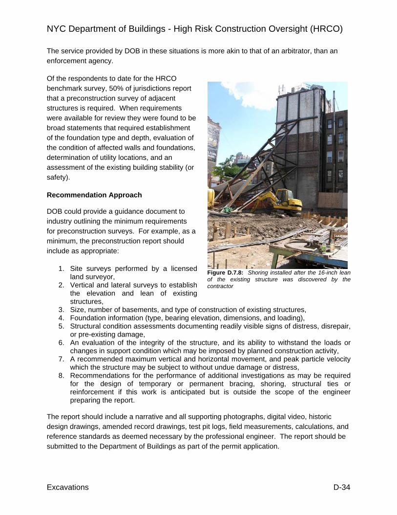
NYC Department of Buildings - High Risk Construction Oversight (HRCO)
Excavations D-34
The service provided by DOB in these situations is more akin to that of an arbitrator, than an enforcement agency.
Of the respondents to date for the HRCO benchmark survey, 50% of jurisdictions report that a preconstruction survey of adjacent structures is required. When requirements were available for review they were found to be broad statements that required establishment of the foundation type and depth, evaluation of the condition of affected walls and foundations, determination of utility locations, and an assessment of the existing building stability (or safety).
Recommendation Approach DOB could provide a guidance document to industry outlining the minimum requirements for preconstruction surveys. For example, as a minimum, the preconstruction report should include as appropriate:
1. Site surveys performed by a licensed land surveyor,
2. Vertical and lateral surveys to establish the elevation and lean of existing structures,
3. Size, number of basements, and type of construction of existing structures, 4. Foundation information (type, bearing elevation, dimensions, and loading), 5. Structural condition assessments documenting readily visible signs of distress, disrepair,
or pre-existing damage, 6. An evaluation of the integrity of the structure, and its ability to withstand the loads or
changes in support condition which may be imposed by planned construction activity, 7. A recommended maximum vertical and horizontal movement, and peak particle velocity
which the structure may be subject to without undue damage or distress, 8. Recommendations for the performance of additional investigations as may be required
for the design of temporary or permanent bracing, shoring, structural ties or reinforcement if this work is anticipated but is outside the scope of the engineer preparing the report.
The report should include a narrative and all supporting photographs, digital video, historic design drawings, amended record drawings, test pit logs, field measurements, calculations, and reference standards as deemed necessary by the professional engineer. The report should be submitted to the Department of Buildings as part of the permit application.
Figure D.7.8: Shoring installed after the 16-inch lean of the existing structure was discovered by the contractor

NYC Department of Buildings - High Risk Construction Oversight (HRCO)
Excavations D-35
The list provided above is intended to identify the major categories of a typical examination and investigation survey. Depending upon the age, condition, landmark status, value, and proximity of the structure to the planned construction, some categories may be omitted, or additional detail may be required in any one or all of the categories mentioned. It is expected that the responsible engineer will make use of various investigative tools (supplemental borings, test pits, structural cores, probes, etc.) and research historic records as necessary to determine the information required for design.
Additional HRCO Observations Although often found lacking on permit drawings, information describing the adjacent structures (e.g., site surveys, geotechnical reports, original design drawings, and in some cases actual preconstruction surveys) can be produced when requested by the Special Enforcement Unit for Excavations as a part of a Stop Work Order engineering audit. In some cases it appears that the documents may not have been made available to all members of the design team.
The recommendation is intended to help clarify the design and construction due diligence requirements that are unique to the dense, built-out urban environment of New York City. The recommendation is directed toward improving compliance with existing requirements.

NYC Department of Buildings - High Risk Construction Oversight (HRCO)
Excavations D-36
D.10 RECOMMENDATION E-4: MONITORING DURING EXCAVATIONS The excavation, earth retention system, or underpinning designer should identify all influenced structures, and should establish a monitoring program for the construction operation, meeting minimum requirements established by DOB.
Description Most monitoring programs (exclusive of those associated with Landmark structures) are instituted at the discretion of the General Contractor. When questioned contractors stated that they rely upon visual identification of damage or distress (cracking, distortion, owner complaint, etc.) in surrounding buildings before initiating any monitoring program. A significant degree of damage may have occurred prior to becoming noticeable to the visual observation.
Where lateral building movements are monitored, it is generally done using optical instruments by a subcontract surveyor. The use of inclinometers to measure ground movements behind an earth retention system is not widespread, although tiltmeters are used occasionally to evaluate building movements.
Of the active sites visited by the HRCO, roughly 30% did not have a monitoring program in place during excavation operations.
Figure D.10.1: Monitoring of adjacent structures Figure D.10.2: Number of sites with monitoring (by category)
About 21% of the sites had damage to adjacent structures (settlement or visibly discernable distress) which could be attributed to earth retention and/or underpinning operations.
Survey or Vibration
70%
No Monitoring
30%
0
5
10
15
20
25
30
Surv
ey
Vibr
atio
n
Tiltm
eter
s
Cra
ck G
auge
Non
e
B o ro ug hsM anhat t an

NYC Department of Buildings - High Risk Construction Oversight (HRCO)
Excavations D-37
Figure D.10.3: Extensive structural cracking of upper stories with superficial repair
Figure D.10.4: Cracking and lateral displacement of below grade wall during underpinning
Soil or pavement settlement behind installed earth retention systems was observed at 17% of the sites.
Figure D.10.5: Sidewalk cracking and subsidence extending to the curbline
Figure D.10.6: Localized soil loss and structural collapse of unsupported sidewalk
Of those jurisdictions that have responded to the HRCO benchmarking survey, 60% reported that monitoring of adjacent structures is required during construction. Surveying to evaluate vertical and lateral movements and vibration monitoring are the most common requirements.
The 1968 NYC Building Code does not contain any provisions for monitoring. A Technical Policy and Procedure Notice was issued in 1988 for Landmark structures.

NYC Department of Buildings - High Risk Construction Oversight (HRCO)
Excavations D-38
TPPN 10/88 - Procedures for the Avoidance of Damage to Historic Structures Resulting from Adjacent Construction When Subject to Controlled Inspection by Section 27-724 and for Any Existing Structure Designated by the Commissioner. The architect or engineer designated for Controlled Inspection of Construction Required for or Affecting the Support of Adjacent Properties or Buildings required by Section 27-724 (C26-lll2.6l shall institute a monitoring program for adjacent historic structures and for any existing structure designated by the Commissioner.
The program includes:
Establishment of a peak particle velocity design criteria during the driving of sheeting or blasting operations. The maximum permissible peak particle velocity shall be 0.5 in/sec (13mm/sec) with no distance criterion, and the maximum permissible peak velocity shall be reduced if movements or cracking is detected.
Establishment of criteria for any temporary retaining wall structure. The maximum permissible horizontal and vertical movement of the temporary retaining wall system shall be designed in accordance with generally accepted engineering practice. Establishment of movement criteria for the historic building. The maximum permissible movement shall be 0.25 in (6mm). Establishment of criteria for ground water. The lowest water level shall be determined by periodic ground water monitoring at observation wells, seasonably adjusted and designated as the "low datum" prior to the start of the excavation operations. Limitation on water drawdown shall be considered in the criteria for the retaining system.
The 2008 Building Code includes a broad requirement for monitoring under Chapter 18:
1814.3 Monitoring of influenced structures. A land surveyor or engineer shall monitor the behavior of influenced structures during construction and for as long as necessary after construction concludes, as determined by the commissioner.
The HRCO has not identified any conflict between the existing code language and the proposed recommendation. It should be noted that the landmark building displacement and vibration criteria is likely to be too restrictive for general construction. Recommendation Approach DOB could provide a guidance document to Industry outlining the minimum requirements for monitoring of influenced structures.
Influenced structures should be identified by the engineer, based on the type of operations being conducted. Considerations for defining influenced structures could include (but should not be limited to):

NYC Department of Buildings - High Risk Construction Oversight (HRCO)
Excavations D-39
1. Shares a common wall, footing or foundation, or other structural element with the construction site, or
2. Is sited immediately adjacent to the property line nearest the construction activity, or 3. Is sited within the effective radius of construction related vibrations, or In the case of excavations or below ground work 4. Is sited such that any footing or foundation bearing elements are located within the area
that projects upward from the base of the cut on a 45 degree angle, or 5. Is sited such that grade-supported elements, or portions thereof, are located within the
area that projects upward from the base of the cut on a 45 degree angle, or 6. Is sited such that the invert of an existing utility is located within the area that projects
upward from the base of the cut on a 45 degree angle. The zone of influence should be measured from the nearest point of the construction activity to the structure being evaluated. The above definition of zone of influence serves as a default based on common practice. The designer must make the judgement as to whether the surrounding structure qualify as influenced.
The details of the monitoring program should be included in the design drawings submitted to the Department of Buildings for permit. As a minimum, the details should include the type of instrumentation, installation requirements and locations where applicable, schedule of readings and reporting, threshold and maximum limit criteria for vertical and horizontal movement, threshold and maximum limit criteria for permissible peak particle velocities associated with vibrations, contact information for the designer and the Department of Buildings, notification and construction procedures should the threshold criteria be exceeded.
Additional HRCO Data Studies (Clough and O’Rourke, 1990; Son and Cording, 2005) indicate that 2 to 3 inches of settlement can occur before visual evidence of distress is apparent. Most underpinning design documents, texts, and publications state that vertical movements of 0.25 to 0.5 inches should be expected with typical concrete underpinning.
Most vibration monitoring programs are based on, or make reference to, the U.S. Bureau of Mines Report of Investigation 8507 (Siskind et al., 1980b). The study focused on homes located adjacent to mining facilities with active blasting. Velocity time histories were obtained outside those structures that sustained threshold sized cracks. No blasts with dominant frequencies below 5 Hz or above 40 Hz (construction level) were monitored during the observation period.

NYC Department of Buildings - High Risk Construction Oversight (HRCO)
Excavations D-40
The limit shown by the solid line was developed only as an initial proposal for frequency control. It was not intended to be used as regulatory tool.
According to Cording
In most states, allowable construction induced ground motions range from 0.5 to 1.0 inches per second (in/sec) and under certain conditions up to 2.0 in/sec. However, ground motion as low as 0.02 in/sec can be perceived, and repeated motions throughout the day as low as 0.1 in/sec can cause annoyance… Cosmetic cracking from construction vibrations has not been observed below peak particle velocities of 0.8 in/sec.
The City of Toronto has recently enacted By-Law No. 514-2008, “To amend City of Toronto Municipal Code Chapter 363, Building Construction and Demolition, with respect to regulation of vibrations from construction activity.” It includes provisions for maximum permissible vibrations, a vibration control form, and requirements for preconstruction inspection and monitoring. The maximum permissible vibrations are actually slightly more restrictive than the standard U.S. Bureau of Mines chart.
A broader reinterpretation of vibration monitoring was developed for the Boston Central Artery project. The requirements included consideration of the source of vibration and the type (and condition) of the structure being affected. The project specifications included a provision that required the design engineer to establish thresholds for acceptable vibrations for the relevant section of the awarded work. The thresholds were required to be below the maximum values defined by the Massachusetts Highway Department.
Figure D.10.7: Frequency-based velocity criteria (US Office of Surface Mining)
CITY OF TORNTO BY-LAW NO. 514-2008 Table 1.0: Prohibited Construction Vibrations
Frequency of Vibrations Vibration Peak Particle Velocity (hertz) (mm/sec) (in/sec)
Less than 4 8 0.3 4 to 10 15 0.5 More than 10 25 1 Figure D.10.8: Vibration criteria for Toronto

NYC Department of Buildings - High Risk Construction Oversight (HRCO)
Excavations D-41
Additional HRCO Observations Risks to structures, workers, and the public can be mitigated by proactive, rather than reactive monitoring. When monitoring is active, construction practices which are contributing to ground movements can be identified and arrested before surrounding buildings are damaged by the activity.
The visual inspection of surrounding structures should not be relied upon as a useful means of monitoring. While all structures are different, a practical limit on settlement and lateral movement should be developed. Industry should be required to provide thresholds, for their own interests, the safety of others, and to demonstrate that the surrounding structures are adequately being protected by the design. The thresholds serve as alerts to control the
Massachusetts Highway Department – Central Artery Tunnel Design Policy Memorandum No. 1 (Rev 4)
Table 1: Vibration Acceptance Criteria Table 2: Structural Categories
Source M Source S Structural Category Definition
f Vmax F Vmax Foundation: Competent foundations Structural Category
(Hz) (in/sec) (Hz) (in/sec) Framing: Reinforced concrete, steel or timber
1 - 30 0.5 10 - 60 1.2 Interior Finish: No plaster
I 30 - 60 0.5 - 0.7 60 - 90 1.2 - 1.6
I
Examples:
Industrial buildings, bridges, masts, concrete retaining walls, unburied pipelines
1 - 30 0.3 10 - 60 0.7 Foundation: Concrete or competent masonry II
30 - 60 0.3 - 0.5 60 - 90 0.7 - 1.0 Framing: Any framing except as described in III below
1 - 30 0.2 10 - 60 0.5 Interior Finish: No plaster
III 30 - 60 0.2 - 0.3 60 - 90 0.5 - 0.7
II
Examples:
Engineered concrete and masonry buildings, masonry retaining walls and buried pipelines
1 - 30 0.12 10 - 60 0.3 Foundation: Less competent masonry
IV 30 - 60 0.12 -
0.2 60 - 90 0.3 - 0.5 Framing: Horizontal timber framing supported on masonry walls
Source M: Continuous or steady state vibration such as vibratory pile drivers, hydromills, large pumps and compressors, bulldozers, trucks, cranes, scrapers, and other large machinery including jackhammers, reciprocating pavement breakers and compactors
Interior Finish: Any finish including plaster
Source S: Transient or impact vibration such as blasting with explosives, drop chisels for rock breaking, buckets, impact pile drivers, wrecking balls and building demolition, gravity drop ground compactors and pavement breakers
III
Examples: “Non-engineered” buildings
IV Buildings that are extremely susceptible to damage from vibration
Figure D.10.9: Structure and source based velocity criteria for vibrations

NYC Department of Buildings - High Risk Construction Oversight (HRCO)
Excavations D-42
excavation. As the enforcement authority, the Department of Buildings should provide (and industry will undoubtedly expect) the non-exceedance, or maximum, limit.
For settlement, a maximum of 0.75 to 1 inch is probably a reasonable limit for most modern steel and reinforced concrete structures. For a majority of modern steel and reinforced concrete structures on continuous or spread-type footings, a vertical foundation settlement in the range of 1 inch is often incorporated into the design. Lateral movements at the foundations should not be more than 1 inch. The sway of the structure is the main concern, and the height must be considered. Again most structures incorporate some lateral movement in their design. However, regardless of what not-to-exceed limit that might be set by DOB, the designer must set structure-specific thresholds. This is particularly important in NYC given the significant number of older and potentially fragile structures.
For vibrations, the standard nuisance-based 0.5 in/sec criteria is a reasonable limit. Most construction complies with the current requirement. However, given the increase in the size and capacity of construction equipment (and the growing preference for rock excavation in New York City) an increase to 1 in/sec may be prudent.
Obviously, modern structures can resist slightly more movements, fragile structures considerably less. Anything more restrictive than the suggested limits would be difficult to demonstrate in advance given the degree of accuracy of performance prediction in most analyses. The key component is for industry to recognize the need to make the predictions as part of the design, and then to verify the performance during construction.
It should also be recognized that the maximum limits established by the Department of Buildings, will inevitably be too restrictive for some projects. In such cases, a mechanism will be necessary for professional engineers to appeal the maximum limits. The appeal should be justified by sufficient documentation and calculation to demonstrate that the approach being considered is the best available, that the risk is being managed to the best extent possible, and that the oversight will be extensive.

NYC Department of Buildings - High Risk Construction Oversight (HRCO)
Excavations D-43
D.11 RECOMMENDATION E-5: MINIMUM DRAWING STANDARDS Design submittals for excavation, earth retention, or underpinning permits should include sufficient plan, section, and detail drawings as necessary to convey the full intent and scope of the construction. DOB should establish minimum requirements for submittals.
Description
The quality and content of drawings submitted for permit is currently addressed as a “Standard Practice” issue. Designers are expected to provide a level of detail sufficient to enable local contractors familiar with the activity to bid and either directly build, or develop construction drawings from the permit documents.
Largely to facilitate their own review, major metropolitan areas such as Chicago, Los Angeles, and Seattle have published documents, or made them available on building department websites, that detail the minimum requirements (content and supporting documentation) of excavation, earth retention, and underpinning design submittals. The guidelines have the effect of standardizing submittals, enabling reviewers to concentrate on the engineering (suitability and performance) aspects of the design rather than auditing for content.
The quality and content of on-site permit drawings vary extensively from job to job. Site information relating to adjacent structures, utilities, streets, and the public right-of-way is often incomplete or absent from the drawings altogether.
Data provided by the NYC DOB Special Enforcement Unit for Excavations shows:
1. More than 2,520 sites inspected between July 2007 and December 2008 2. Approximately 54% (1,370) were in Support of Excavation (SOE) Phase 3. 56% (764 of 1,370) of inspections resulted in a Stop Work Order (SWO) 4. 66% (503 of 764) of SWO sites were audited by SEU Engineers 5. 84% (424 of 503) failed initial audit
In response to their findings, the SEU is drafting a “Support of Excavation (SOE) Requirements” document. The purpose of the self-described bulletin is to define what constitutes "adequate" construction documents pursuant to 27-157, 27-162 (1968 BC) and 28-104.7.1, BC 106.7, BC 106.8 (2007 NYC Construction Code), and “Berger Memorandum” of 12/05/1986 as related to Support of Excavation (SOE) and related foundation work.
Based on the drawings reviewed by the HRCO, coordination and cooperation between the architect, structural, and subgrade designers do not always seem to be sufficient to provide a suitable, cost-effective design. In some cases “boiler-plate” details are substituted for site-based design to secure a permit. The details are often incomplete and they are not suitable for construction.

NYC Department of Buildings - High Risk Construction Oversight (HRCO)
Excavations D-44
When questioned, designers complained that they were unaware of any standard defining the content of design drawings. The excavation, earth retention, and underpinning design is not considered to be an integral part of construction, and it is often overlooked (or ignored) until late in the project timeline. The process of Professional Certification is commonly used to accelerate the permitting process.
Inadequacies (ranging from minor elevation issues to potentially un-constructible details) were identified at approximately 46% of the active construction sites where earth retention system drawings were available for review by the HRCO.
Minimal dimensioning is provided on permit drawings. Most plan drawings do not tie the design into a fixed reference point that could be verified in the field. Elevations (e.g., foundation bearing, wale or anchor, existing grade) are commonly omitted, and in many cases, the lateral and vertical dimensions must be interpreted by scaling. Frequently, the architectural, structural, and earth retention drawings do not reference a common project elevation. Design information for adjacent structures and facilities (foundation bearing elevation, offset from property line, footing dimensions, etc.) is not consistently included in cross-sections.
Permitted earth retention and underpinning design drawings are commonly used as construction documents. Revised drawings are not typically issued to address obstructions or changed conditions that necessitate field changes by the contractor, or to reflect material substitutions. Verbal consent of the designer for the changes is generally related by the contractor.
Recommendation Approach DOB could provide a guidance document to industry which defines the minimum content requirements for excavation, earth retention, and underpinning design drawings submitted for permit. (Note: monitoring of adjacent and influenced structures is discussed in a separate recommendation).
Content in design drawings should accurately depict the following:
1. Site Plan (Basic Elements)
a. Adjacent buildings (no. of stories, basements, type of construction, etc.) b. Existing known utilities c. Property lines
Figure D.11.1: HRCO Drawing review (in field)
Inadequate46%
Adequate54%

NYC Department of Buildings - High Risk Construction Oversight (HRCO)
Excavations D-45
d. Streets and sidewalks e. Excavation limits and slopes f. Foundations and/or column lines for proposed construction g. Earth retention components (soldier piles, sheet pile, timber shoring, etc.) h. Underpinning alignment with sequence i. Anchorage components (tiebacks, internal bracing, rakers, etc.) j. Dewatering criteria k. Section callouts l. North arrow
2. Site Plan (Dimensions) a. Elevation reference b. Setback and encroachment of foundation elements c. Retention system offset from property lines and utilities d. Center-to-center spacing of soldier piles e. Extent of retention system and/or underpinning
3. Cross-Sections (Earth Retention System) a. Subsurface soil and groundwater conditions b. Existing foundations (type, dimensions, and bearing elevation) c. Existing utilities (type, dimensions, and bearing elevation) d. Streets and sidewalks e. Offset (to foundations and utilities) and encroachment dimensions f. Existing grade, intermediate stages, and final excavation elevations g. Surcharge assumptions h. Temporary earth berm dimensions i. Top and tip elevation of sheeting and soldier piles j. Anchor and wale elevation k. Anchorage dimensions (tieback, bracing, raker, and deadman) l. Installation and excavation staging sequence m. Groundwater levels assumed for design n. At least 1 section at each side of excavation o. At least 1 typical section that extends beyond the active zone of the
excavation
4. Cross-Sections (Underpinning) a. Subsurface conditions (soil/rock type and groundwater) b. Existing foundations (type, dimensions, and bearing elevation) c. Bearing elevation and allowable bearing pressure d. Lift sequence, box pit and pin dimensions e. Approach pit dimensions and excavation slopes f. Bracing and/or shoring for sideslopes of approach pits g. Box pit dimensions and shoring h. Anchorage or bracing elevations and dimensions i. Installation sequence j. Groundwater level assumed for design k. Shimming or dry pack requirements and schedule l. At least 1 section at each adjacent building m. Shoring details for existing superstructure (if applicable)
5. Anchorage (Grouted Tiebacks or Alternate)

NYC Department of Buildings - High Risk Construction Oversight (HRCO)
Excavations D-46
a. Soil or rock type in bond zone b. Bonded and unbonded length c. Diameter of bond zone d. Design capacity and lock-off load e. Component sizes (threadbar, hollowbar, tendon) f. Inclination angle g. Grout strength h. Proof and production test requirements and schedule i. Raker or bracing component sections and dimensions j. Raker or bracing design loads and prestress (if applicable)
6. Connections, Misc. Details, and Specifications a. Size/extent of welds b. Electrode type c. Stiffener plates (spacing and dimensions) d. Wale support and/or knee brace dimensions e. Bearing plate dimensions f. Splice detail
7. Material specifications (steel grade, lagging, concrete strength, etc.) a. Reinforcement b. Bar and dowel sizes c. Spacing d. Lengths e. Bend requirements
8. Dewatering Plan (typically by specialty contractor other than excavation, earth retention, or underpinning designer)
a. Layout plan (well point, well, sump locations, etc.) b. Pump size c. Anticipated flow d. Anticipated drawdown radius e. Discharge point and volume f. Groundwater monitoring/testing requirements
The list provided above is intended to address the major components of a typical excavation, earth retention, or underpinning design. Depending upon the complexity, risk, and timeline of the construction some items may not apply, or additional detail may be required in any one or all of the categories mentioned. Unique site conditions (management and control of surface water, temporary impoundment of spoil, and stockpiling of debris, etc.) should be depicted when they can directly affect the construction operation, and may impact the structures, facilities and safety of individuals beyond the property limits.
NYC Department of Buildings - High Risk Construction Oversight (HRCO)
Excavations D-47
Additional HRCO Observations In addition to defining a “Standard Practice” the establishment of nominal content is a pre-requisite for efficient and effective review. It is expected that published guidelines will result in a greater emphasis on due diligence and internal review among designers prior to permit submittal. In addition, contractors will be provided with a more consistent product from which to bid and build.

NYC Department of Buildings - High Risk Construction Oversight (HRCO)
Excavations D-48
D.12 RECOMMENDATION E-6: LIMITED TECHNICAL REVIEW Require pre-permit technical review of excavation, earth retention system, and underpinning permit designs.
Description
The New York City Department of Buildings created the Special Enforcement Unit for Excavations (SEU) in 2007. The unit operates City-wide. The engineering audits performed by this unit act as a de-facto technical review during construction. The audits are triggered by referrals from inspectors in conjunction with issuance of a Stop Work Order.
Projects that are referred for audit must supply documentation (including site plans, design drawings, site investigation reports, etc.) to the assigned SEU engineer. The engineer may also perform a site visit to retrieve on-site design drawings and confirm the findings of the inspector. The engineer reviews the provided drawings and documentation and compiles a list of objections which is provided to the designer.
After the designer has made drawing revisions to the satisfaction of the SEU engineer, the project is recommended for a Stop Work Order rescind. An on-site meeting is scheduled with the inspector that issued the order, and once satisfied with the measures taken to correct the drawings and construction procedures the Stop Work Order is rescinded.
According to SEU statistics, the audit process in times of peak construction can average 28 days or more. The final rescind of the Stop Work Order may lag the engineer’s recommendation by several days to a few weeks depending upon the scheduling of the inspector and the state of the construction site at the time of the re-inspection.
NYC Industry Practice The current Department of Buildings practice of submittal reviews based on fire, egress, and zoning will not capture technical deficiencies or incomplete subgrade site designs. Random audits are performed infrequently and are not standardized.
Other local NYC agencies (e.g., MTA and DEP) already require technical review of submittals which affect their structures and facilities.
The Special Enforcement Unit for Excavations (SEU) has initiated - and through their outreach efforts made industry aware of - a pre-submittal audit service for excavation, earth retention, and underpinning permits. The program is a voluntary consultation service for designers, and it is offered by appointment.
The SEU has indicated a preference to require, initially, a technical review of all sheeting/shoring/bracing and underpinning permits related to new building (NB) permits. For the fiscal year of 2007 (ending July 2007), the SEU reported that 5,600 NB permits were

NYC Department of Buildings - High Risk Construction Oversight (HRCO)
Excavations D-49
issued. For 2008 the number dropped to about 4,200 permits, and it is projected to be approximately 2,500 to 3,000 at end of 2009. Once the review program has been established for NB permits, the scope would expand to all applications (Alt 1, 2, and 3) involving excavation, earth retention, and underpinning.
In order to identify and improve tracking of Alteration-type permits, the SEU has considered adding two new work and permit types specifically for support of excavation (SOE) and underpinning.
The engineers within the SEU currently audit permit drawings for projects that are referred by their field inspection staff. Between July 2007 and December 2008, the SEU audited roughly 500 of the 2,500 sites inspected. The failure rate of the permitted drawings was reported to be 84%.
The HRCO review of design drawings identified inadequacies including potentially un-constructible details in 46% of those available for review.
According to the responses received to date from the HRCO benchmarking survey, approximately 62% of jurisdictions polled perform a detailed or partial technical review of plans and calculations in advance of permitting for temporary works (essentially excavations and earth retention systems). Self-certification (equivalent of NYC Professional Certification) was reported in 38% of the jurisdictions.
When defined as permanent systems (underpinning or integrated retention/foundation systems such as slurry walls or secant piles) nearly 88% of jurisdictions stated that detailed or partial technical review was performed. A self-certification program for permanent systems was in place in only 25% of the jurisdictions.
Depending upon volume, staff size, and level of expertise required, the reviews may be performed by full-time building department engineers, or they may be subcontracted to local specialty engineering firms.
Recommendation Approach As a minimum plan submittals for excavations, earth retention systems, and underpinning designs that extend more than 10 or 12 feet below existing grade should be technically reviewed as a pre-requisite to permit approval by the Department of Buildings. Submittals for designs that extend less than defined depth below grade would not be excluded from review, but those reviews would be performed at the discretion of the Department of Buildings. The technical review should include, but not be limited to, code compliance, soundness of the analysis, completeness of the drawing package, and feasibility of the construction. DOB should review the results of the technical review on a regular basis to assess whether review of a greater (or lesser) number of permits is warranted.

NYC Department of Buildings - High Risk Construction Oversight (HRCO)
Excavations D-50
The existing grade should be defined relative to the pre-construction site grade, or the average grade of the surrounding properties, streets, and sidewalks. Existing grade should not include mass excavation to lower site grades unless that excavation is performed to lower the permanent site grade to a level equivalent to surrounding properties. For example, the 2009 IBC defines the grade plane as:
“A reference plane representing the average of finished ground level adjoining the building at exterior walls. Where the finished ground level slopes away from the exterior walls, the reference plane shall be established by the lowest points within the area between the building and the lot line or, where the lot line is more than 6 feet (1829 mm) from the building, between the building and a point 6 feet (1829 mm) from the building”
In the case of open cut excavations (i.e., angle of repose) the defined depth could refer to the deepest extent of soil removal below existing grade.
In all other cases, the defined depth could be applied to the penetration below existing grade of the components which support the excavation (e.g., soldier piles, sheet piles, underpinning pit or pier).
The professional engineer responsible for an excavation, earth retention system, or underpinning design subject to review would provide copies of all design drawings, site assessment reports (including but not limited to site surveys, precondition surveys, geotechnical investigation reports), supporting calculations, and relevant reference materials as may be requested by the commissioner.
Additional HRCO Observations If the volume of permit applications remains at the levels forecast by the SEU, a staff of 5 engineers would need to review about 50 to 60 applications per week. These reviews would only address excavations, earth retention and underpinning associated with NB permits. If the remaining permit types (Alt 1, 2, and 3) are added to the queue the workload would be expected to increase substantially.
According to the data published on the BIS website, for the period from January through August 2008, the Alt 2 filings ranged from about 3,500 to 5,000 per month. Assuming only a small fraction of the submittals involve excavation, earth retention, or underpinning the review workload could potentially double.
We have suggested using a depth criteria of 10 to 12 feet as a screening tool to reduce the volume of submittals for which a review by DOB would be mandatory. If review of all submittals is considered additional staff hires, or subcontracting reviews to local engineering firms would be the most likely means to accommodate the greater work flow.
NYC Department of Buildings - High Risk Construction Oversight (HRCO)
Excavations D-51
D.13 RECOMMENDATION E-7: UNDERPINNING NOTIFICATION The contractor should notify the Department of Buildings a minimum of 24 hours, but no more than 72 hours (3 working days) in advance of the start of underpinning construction. The notification should be written, and it should include a brief narrative description of the activity including the length and location of underpinning to be installed, height of typical pit or pier, and the estimated duration of construction. The contractor should also be required to provide the same notification to the underpinning designer and to the responsible agent for special inspections if different from the designer.
Description Under the 1968 code underpinning was identified as a construction procedure for which special inspection is mandatory. The same requirement was adopted into the 2008 NYC Building Code.
Title 1 of the Rules of the City of New York was amended by adding a new Chapter 52 which for expediency of reference is reproduced below. Rule (now Chapter) 52 is a one-time notification requirement related to commencement of excavation activity on a particular site. It does not include provisions for defining the nature of the work, or its anticipated duration.
Effective October 25, 2006, all contractors obtaining permits to conduct earthwork were required to notify the Buildings Department within 24 - 48 hours of the start of excavation by calling (212) 227-4416 per 1 RCNY § 52-01. The permit holder must also notify the Department of delays or cancellations of the work by calling no later than the date the originally specified work was scheduled for (but no more than 24 hours prior to).
The Special Enforcement Unit for Excavations cross references Rule 52 notification data with the New Building and Alteration-type permit issuances to prioritize inspections. Because compliance is not 100% throughout all the Boroughs, inspections are also routed to sites with excavation related permits for which notification could not be verified.
A note regarding Rule 52: it was folded into the new 2008 construction codes – part of BC 3304.3.1. Rule 52 has thus been repealed, and in the balance of this report such actions are referred to as excavation notification requirements.
If the permit holder does not provide notification of the intended earthwork, a violation for “failure to notify” may be written. The Commissioner may issue a minimum three-day Stop Work Order if work is found to violate any of the provisions of the Building Code, Zoning Resolution or other applicable laws, rules or regulations at a site where proper notice was not provided as required.
Compliance with excavation notification requirements is almost universal at larger and mid-size projects in Manhattan. Compliance in the outer Boroughs was difficult to verify, but it is believed to be somewhat less consistent than in Manhattan. When questioned, nearly all moderate and

NYC Department of Buildings - High Risk Construction Oversight (HRCO)
Excavations D-52
large-size contractors in the Boroughs admitted to being aware of the requirement. The smaller contractors, and those few questioned in Staten Island, were either not aware of the requirement, or felt that it was not their responsibility.
HRCO sites were selected from a list of New Building permits compiled by the NYC DOB Special Enforcement Unit (SEU) for Excavations. The list included more than 3,000 permit filings for all 5 New York Boroughs. Sites were sorted by various means (e.g., Borough, cxcavation notification requirements, key words in the application description, etc.) to create a sublist of sites where excavation, shoring, and/or underpinning activities were anticipated.
The sites selected from the sublist were cross-checked by address on the NYC DOB Building Information System (BIS). Filings and actions were reviewed to determine project status and to identify sites where subgrade work was potentially in progress.
This method of identification produced an overall “hit” rate of active sites (defined as a contractor on-site and available access) in the range of 40 to 45%. In the month of August rates for the HRCO were as low as 35% in some cases. Given the limited available data to make the selections, “hit” rates on initial site visits would not be expected to exceed about 45% without pre-notification.
The SEU process of site selection is similar, although it is augmented by referrals and complaints. Even with the additional information, hit rates estimated by the SEU did not exceed 50 to 60%.
In both cases, however, the likelihood of visiting a site during actual underpinning (or earth retention installation) is much less than the numbers would indicate. The duration of underpinning is often less than a few weeks in a multi-month, or even multi-year project. The startup is highly dependent upon the excavation schedule and the contractor’s organizational work plan.
The participants in the Excavation Subcommittee meetings cited a lack of notification for site activity as a major impediment to special inspections. Anecdotal reports included:
1. Requests for inspection after completion of the underpinning, 2. No notification by the contractor, and 3. Demands by owners that the construction be certified despite the lack of inspection
opportunity. Additional HRCO Observations The NYC DOB issues site-wide underpinning permits associated with the new building address. Although the permit may be approved and issued, the permission of the affected owner is still required before underpinning construction can begin.

NYC Department of Buildings - High Risk Construction Oversight (HRCO)
Excavations D-53
Because it is a one-time requirement, the excavation notification requirements (formerly “Rule 52”) are no longer useful as an indicator of underpinning construction activity. The SEU indicated that the current policy is to ask whether or not underpinning will be performed as a follow-up question when notification is performed. Under the present system, underpinning may not occur for weeks or even months after the excavation notification is provided. If the permits were individual (and filed under the address upon which the underpinning was to be performed), the associated notification of start of excavation for each address could reasonably be expected to be a notification of the start of underpinning. Although the tracking of so many potentially divergent but inter-related permits would likely be unmanageable.
“Underpinning Notification” is intended to help make site construction activity more transparent. The underpinning notification will enable the SEU to route their inspection personnel more effectively to a high-risk operation.
Although the activity requires special inspection, there is no penalty to the contractor for failing to provide adequate notice. It is believed that if contractors are required to directly notify the NYC DOB, the notification of the designer and special inspector will also improve by default.

NYC Department of Buildings - High Risk Construction Oversight (HRCO)
Excavations D-54
D.14 RECOMMENDATION E-8: TR1 AND INSPECTION LOG Critical inspection information, including the TR1 form and a log of special and progress inspections should be maintained on site for the benefit of the construction parties and DOB.
Description Under the 1968 and new 2008 NYC Building Code, a TR1 form must be filed with the permit application. The form is used to define the responsible registered architect or professional engineer for a project, and designate the special inspection architect or engineer. Until recently a single TR1 was filed for the project. Under the current process, separate TR1 forms must be filed for each permit, and additional forms must be submitted for each construction activity (e.g., underpinning or earth retention) with independent designers.
The special inspection engineer or architect determines the number of inspections to be performed for each construction activity and must maintain a log in his/her office of the completed inspections. The code requires that the minimum number of inspections “…shall not be less than two,” and at least one inspection must be pre-construction. The log must be provided to the Department of Buildings upon request for review.
The TR1 form is rarely maintained on-site, and if it is, it may not represent the current responsible parties. Contact information must be obtained from separate documents, and it is often difficult to determine which special inspection architect or engineer is responsible for the various construction operations which may be occurring simultaneously.
The TR1 is currently filed electronically and accessible through the BIS website. The copy on file generally represents the document submitted at the time of permit request. It may be submitted by the owner, the designer, the project architect, structural engineer, or an expediter. When filed by an individual other than the designer, it is often submitted as a “ghost-form” wherein the person assuming responsibility for inspection does so with the sole intent of transferring that responsibility after the permit is issued. The withdrawal of the original applicant and designation of a replacement may not be completed at the time of construction.
The TR1 form was available at less than 5% of the active construction sites visited by the HRCO.
The special inspector was on-site at less than 6% of active construction sites.
About 35% of the contractors (or other site contacts) could not identify the special inspector – 3 sites claimed there was none, and several incorrectly identified the QA/QC representative.
Of those that could identify the special inspector, less than 50% could provide the date of the last site visit.

NYC Department of Buildings - High Risk Construction Oversight (HRCO)
Excavations D-55
Earth Retention Inadequate construction or variation from permitted design was identified at approximately 36% of sites with earth retention systems.
Field variations from permitted design (e.g., changes in member sizes, omitted bracing, substitution of lagging) comprised the largest percentage of deficiencies. Incorrect layout of soldier piles and spacing of lateral bracing was the second largest percentage.
Figure D.14.1: Earth retention system deficiencies observed by site
Figure D.14.2: Earth retention deficiencies observed by category
Figure D.14.3: Typical braced retention system. Close-up at right of inadequate (omitted in this case) weld at stub connection to waler. Underpinning Inadequate construction or variation from permitted design was identified at roughly 26% of sites with underpinning.
Inad eq uat e3 6 %
A d eq uat e6 4 %
W orkmanship15%Details
15%Connections
12%
Layout35%Field
Variations23%

NYC Department of Buildings - High Risk Construction Oversight (HRCO)
Excavations D-56
Failure to comply with the design installation sequence was single largest deficiency for underpinning. Nearly half of the sites at which underpinning construction was in progress violated the installation sequence.
Improper excavation of the approach or box pit comprised the second largest percentage of deficiencies. In many cases the sideslopes of the approach pit were unshored or had slopes significantly steeper than 1:1 (horizontal:vertical). Excavated soil was stockpiled at the edges of the approach pits. Mass excavations along the existing structure were used in lieu of perpendicular excavations equal to the pit or pier width.
When conventional box pits were used, the pit or pier excavation beneath the foundation was advanced with (rather than after shoring and completion) the box pit.
Figure D.14.4: Underpinning deficiencies observed by site
Figure D.14.5: Underpinning deficiencies observed by category
Figure D.14.6: Improper pit excavation Figure D.14.7: Inadequate repair and shimming
Inadequate26%
Adequate74%
Ground Loss14 %
Layo ut7%
Sequence4 4 %
Shimming14 %
A pproach Pit2 1%

NYC Department of Buildings - High Risk Construction Oversight (HRCO)
Excavations D-57
Recommendation Approach The TR1 form is used to identify special inspections, progress inspections, and tests required for compliance by the responsible design applicant. If an agent other than the responsible design applicant is designated by the owner to perform the work, the responsible design applicant is required to certify that the agent engaged by the owner is acceptable.
TR1 Form
A copy of the TR1 form which identifies the current agent responsible for the performance of the special inspections, progress inspections, and tests should be provided to the general contractor, site safety manager, or other managing authority which maintains a full-time presence on the project site.
Contact information (comprising the full employee, supervisor, and company name; company address; general company and direct phone number; and email if applicable) for the design applicant and the responsible inspection agent should be also provided.
The on-site authority should maintain the TR1 and contact information, either directly available on-site or immediately accessible at a field office, and it should be made it available upon request to the Department of Buildings official and the designer.
Inspection Log
The agent(s) responsible for the performance of the special inspections, progress inspections, and tests should maintain a log documenting site visits.
As a minimum, the log could identify the individual performing the inspection or test, the date of the inspection, the location of the inspection relative to the project scope, a brief description of any corrective action as may be required, and a note documenting when and how the corrective action was performed.
The log should be completed by the responsible agent and initialed by the on-site authority.
The log should be maintained by the on-site authority, either directly available on-site or immediately accessible at a field office, and made available upon request to the Department of Buildings official.
Additional HRCO Observations The recommendation is intended to provide an on-site document that can be used by the designer, contractor, and the NYC DOB to identify (and contact where necessary) the individuals responsible for special inspections. The log will provide an on-site record of compliance with the inspection requirements. The documents are intended to be field records,

NYC Department of Buildings - High Risk Construction Oversight (HRCO)
Excavations D-58
and would not replace the submittal of inspection reports and the TR1 sign-off currently required as part of project completion. The intent of the recommendation is to assist the NYC DOB in the performance of their work, and to improve communication between contractors, designers, and inspectors. In cases where the designer does not perform the inspections, the on-site documents will allow the designer to perform a quality assurance check on the inspector during construction.
It is clear from the site observations that the special inspections are too infrequent and often-times inadequate. The majority of deficiencies observed by the HRCO should have been readily identifiable by any reasonably experienced and trained inspector. Because of the variability of the work in terms of duration, method, complexity, contractor schedule, etc., it would be almost impossible to mandate a minimum number of intermittent inspections for excavation related operations. The requirement of full-time inspection is excessive and costly, and it would be heavily resisted by industry.
The designer (not the special inspector) should determine the number of inspections and define the minimum requirements for their performance as part of the project specifications. The determination should be made in consideration of the desired quality of construction and the level of risk the designer and owner are willing to accept in the execution of the construction. The TR1 form could be modified to include an area in which the designer must clearly define the minimum number of required inspections. General language should also be added to explicitly define the responsibility of the owner and the designer as it relates to protection of the surrounding structures and facilities.
The TR1 requires that the designer “accept” the special inspector. Implied in this consent is the acknowledgment that the designer considers the inspector adequately qualified for the performance of the work. Again the designer can best address minimum qualifications in the specifications, but consideration should be given to creating a mechanism which will allow designers to withdraw, or otherwise suspend the construction operation (with the support of the NYC DOB either directly or as an arbitrator) when an inadequate special inspector is selected by others.

NYC Department of Buildings - High Risk Construction Oversight (HRCO)
Excavations D-59
D.15 RECOMMENDATION E-9: PRE-CONSTRUCTION SITE MEETING The contractor should schedule an on-site meeting with the designer and special inspector (as applicable) to walk through the planned operation in advance of the start of construction. The contractor should the notify the Department of Buildings of the time and place of the meeting, and attendance by the NYC DOB should be at their discretion.
Description
An on-site meeting with the designer, contractor, special inspector, and Department of Buildings official in advance of construction to walk through the planned operations. The concept for this recommendation was presented during an industry subcommittee meeting.
The recommendation is designed to re-emphasize the importance of advance site reconnaissance and pre-construction planning. It is believed that a simple site walkthrough can often be sufficient to identify fundamental design flaws and “unanticipated” conditions. While it is unlikely that the NYC DOB could attend all such meetings, the addition of the NYC DOB notification would be expected to encourage compliance with what is ostensibly an existing requirement.
A preconstruction meeting would be important, for example, for identifying neighboring structures that could be sensitive to underpinning operations or ground vibrations.
For the meeting to be of value, industry would likely expect attendance by NYC DOB engineers. Highly experienced, technically proficient inspectors would probably be acceptable alternatives if their qualifications were known to industry, but in general they would expect the meetings to include equivalent peers. The amount of time associated with these meetings should not be expected to be inconsequential, and the addition of this responsibility could reduce the production rate of staff in their existing duties. The recommendation should be viewed as a long-term implementation effort, and the optional participation component is intended to allow the NYC DOB to effectively manage their time and limited resources.
Additional HRCO Observations The inspection of existing structures during construction are addressed within the provisions of Chapter 16 in the 1968 Building Code. Article 16-01 (d) states that “The controlled inspection architect or engineer should determine the frequency of inspections needed…” and “At a minimum, the site must be inspected twice, once at a preconstruction meeting with the contractor…”
A part of the pre-construction meeting, particularly if DOB is in attendance, should be an assessment of the appropriate frequency of inspections. This recommendation is related to E-08 (TR-1 and Inspection Log), and the special inspection data from that recommendation is relevant here as well:

NYC Department of Buildings - High Risk Construction Oversight (HRCO)
Excavations D-60
• The special inspector was on-site at less than 6% of active construction sites.
• About 35% of the contractors (or other site contacts) could not identify the special inspector – 3 sites claimed there was none, and several incorrectly identified the QA/QC representative.
• Of those that could identify the special inspector, less than 50% could provide the date of the last site visit.

NYC Department of Buildings - High Risk Construction Oversight (HRCO)
Excavations D-61
D.16 STATE OF THE PRACTICE This section serves to provide an overview of construction practices in New York City, and to provide definitions of typical geotechnical terms used elsewhere in this report. The majority of excavation work in NYC utilizes well established, but potentially outdated, methods. The reasons for this are manifold, some of which are discussed in this report. Soldier Pile and Lagging and Classical Underpinning, for example, are predominant methods for earth retention and underpinning, respectively. Newer alternatives to these methods exist, and are widely used elsewhere, but less so in NYC. These newer methods are typically less sensitive to design or construction errors and are likely to promote safety.
The fundamental methods of design and analysis of excavations, earth retention systems, and underpinning are the subjects of numerous engineering textbooks and design manuals. Only a qualitative overview of the most common systems is presented in this report. The “modern” systems discussed below have been in widespread use throughout the US and internationally for some time, and in many areas they have largely supplanted the classical labor-intensive methods. The practice of hand-dug underpinning in particular is diminishing as modern systems continue to demonstrate greater safety in construction, more reliable performance, and more rapid installation.
Many of the more modern systems are installed by specialty contractors and that may partially account for their comparatively slow penetration into the New York City marketplace. Local engineers may be unfamiliar with the design aspects, particularly in the cases of proprietary systems, and contractors may be loathe to subcontract to firms that could be competitors. On a per-unit basis the modern systems can also be underbid by an inexpensive labor force. However, when all the factors of design and construction are considered in the cost-benefit analysis, the modern systems may often be cost competitive.
Construction in New York City is predominantly accomplished in a conventional bottom-up manner. After any existing structures slated for demolition are dismantled or removed and the site is cleared, an excavation is advanced to the lowest level of the planned structure, and the building is constructed floor-by-floor to its final height. Depending upon the size of the planned structure and the site-specific subsurface soil and groundwater conditions, foundations may be constructed from pre-existing grade, or from the excavation subgrade. Cast-in-place below-grade walls can be double formed (front and back) or the earth retention system is encapsulated into the wall to serve as a back-side form and/or long-term waterproofing.
In practical terms, the process of design is heavily influenced by - possibly even dominated by - cost. In a dense, built-out, urban environment such as New York City the premium placed on useable space is such that many projects define their scope by the dimensions of the available lot. Property line to property line development is the rule rather than the exception. To maximize the return on investment, owners and developers naturally give first priority of capital resources to superstructure (above-ground) aesthetics and enhancements to habitable space.

NYC Department of Buildings - High Risk Construction Oversight (HRCO)
Excavations D-62
Substructure (foundations, permanent below-grade walls) and the temporary works necessary for construction are direct costs with limited potential for recovery, and there is considerable pressure to reduce these expenditures to whatever extent possible.
The compression of space places restrictions on designers and extends their responsibilities to structures and facilities outside the project site boundaries. As with any site, the selection and design of an appropriate excavation, earth retention, or underpinning system must consider the subsurface conditions, feasibility, and the cost of construction. However, the affect of the construction on the project surroundings is a much more significant consideration for an urban design than it would be for an open-air undeveloped land parcel. The designer is responsible for ensuring that the proposed system will both effectively “enable” the planned construction, and minimize the impact on the pre-existing structures and facilities that surround the site. The designer must consider:
1. The potential loss of foundation support and lateral restraint associated with the advancement of an excavation (resulting from removal of overburden or withdrawal of groundwater),
2. The lateral and related vertical ground movements inherent to every earth retention
system and their magnitude and zone of influence beyond the system boundary,
3. The structural integrity of existing buildings adjacent to the site, and their ability to withstand the loads and movements imposed during installation of the system.
For any excavation, earth retention, or underpinning system, performance should be the basis of design. An engineering estimate of ground and structure movements is part of the design process, and without the predictive analysis there is no means to evaluate the system during construction or in service. The empirical methods outlined by Clough and O’Rourke (1989) and O’Rourke (1992) are generally sufficient to predict movements with a reasonable tolerance for most retention systems. Highly complex systems often require the use of a finite element analysis, but the performance predictions are highly subject to the quality of the data used to define the constitutive soil models, the proper initialization of the model, staging, and the application of loading. Boscardin and Cording (1989) examined 18 buildings affected by braced excavations or tunneling, and they developed an interaction diagram to correlate damage to angular distortion and horizontal strain. With reasonable estimates of the limiting deflection ratio and angular distortion for a structure, the potential for damage and the suitability of possible remedial measures can be assessed based on predicted ground movements.
The retention system and surrounding structures should be monitored during construction to validate the assumptions made in the analyses. The early observed behavior should be used to refine design parameters, improve constitutive soil and structural models, and enhance confidence in the prediction. Where the behavior differs markedly from the prediction, construction should be suspended and the basis of analysis and the suitability of the design should be re-evaluated.

NYC Department of Buildings - High Risk Construction Oversight (HRCO)
Excavations D-63
Structural collapse is not the most common mechanism by which failure of excavations and earth retention systems are typically defined. The control of support system deformations and the accompanying ground movements, adequate groundwater cutoff, and long-term stability are generally considered the most important design considerations. Puller (2003) summarizes the causes of failure as follows:
1. Inadequate site investigations resulting in optimistic design assumptions of soil, rock strength and groundwater conditions
2. Inadequate appreciation by the designer of susceptibility to settlement of adjacent
structures and services
3. Lack of appreciation by the designer of the influence of deflections in the soil support structure and retained soil deformations
4. Inadequate quality of structural detailing
5. Inadequate coordination between designer and constructor
6. Changes in loading from natural conditions – groundwater, tidal states, waves,
temperature - and lack of appreciation by the constructor of the possible consequences of these changes
7. Changes in soil and rock conditions and the lack of appreciation by the constructor of the
possible consequences
8. Bad workmanship in site temporary works. In Puller’s experience, structural failure of braced and anchored walls usually occurs within the strutting or anchorage, or by passive soil failure resulting from inadequate embedment. Sowers and Sowers (1967) state that failures of sheet pile walls and braced excavations are most often caused by the neglect of backfill loads and surcharges related to construction operations, inadequate allowances for deflections, and poorly designed support systems and connection details.
D.16.1 Excavations When the available site area is sufficient to contain the slopes, open cut excavations will be more economical in direct cost and construction time when compared to virtually any earth retention system. The depth and slope of an excavation, and groundwater conditions control the overall stability and movements of open excavations. Seepage and groundwater discharge on to the slopes is often overlooked in the design of open cuts, but it can be a significant source of instability in the excavation.
According to the US Naval Facilities Engineering Command (NAVFAC) design manual, instability in granular soils will not extend significantly below the bottom of the excavation if
NYC Department of Buildings - High Risk Construction Oversight (HRCO)
Excavations D-64
groundwater seepage is controlled. For dry infinite slopes, the stability can be determined simply from the angle of internal friction for the soil and the geometry of the slope.
In cohesive soils, however, the method of analysis must consider both the duration of the excavation and the stress history of the deposit. In normally consolidated soils, short-term slope stability is based on the undrained shear strength of the soils along a failure surface determined from limit equilibrium. Depending upon the project geometry, stability may be heavily influenced by materials located some distance below the base of the excavation. For permanent or long-term excavations, the stability should be based on an effective stress analysis using drained shear strength parameters. Excavations in cohesive soils, particularly in over-consolidated clay, are also subject to bottom heave which is a function of strength, the depth of cut, and the groundwater conditions.
The stability of rock cuts is controlled by the depth and slope of excavation, the joint patterns of the rock mass, in-situ stresses, and groundwater conditions. Slope failures are common in stratified sedimentary rocks, in weathered shales, and in rocks containing platy minerals such as talc, mica, and the serpentine minerals. Failure planes in rock occur most often along zones of weakness or discontinuities (fissures, joints, faults) and bedding planes (strata). The orientation and strength of the discontinuities are the most important factors influencing the stability of rock slopes.
Puller (2003) identifies several commonly used methods to improve the stability of a cut slope:
1. Regrading the profile to a shallower angle, or providing a local soil berm at the toe of the slope,
2. Providing tensioned ground or rock anchors to increase the effective stress on the
potential failure surface,
3. Intercepting the potential failure surface with sheet piles, contiguous piles, or mix-in-place pile walls installed from top of the slope,
4. Providing drainage to reduce pore water pressure and increase the effective stress on
the potential failure surface,
5. Regrading and providing soil reinforcement (e.g., soil nails or mechanically stabilized earth) to improve the composite soil strength of the slope.
The first two methods would most commonly be applied to short-term excavations. Where the slope is long, or expected to remain open and exposed for a significant length of time, intercepting the failure surface, exterior dewatering, or providing horizontal drainage may be cost-effective. The final method is generally applied only to permanent slopes, although when combined with shotcrete, soil nailing can provide a cost-competitive temporary earth support system. The most significant difference between soil nailing and mechanically stabilized (also commonly called reinforced) earth is the direction of the construction operation. Reinforced

NYC Department of Buildings - High Risk Construction Oversight (HRCO)
Excavations D-65
earth is a fill process built from the base of the cut upwards, whereas soil nails are installed as the cut proceeds downward from the ground surface.
For the relatively shallow cuts that would expected at most construction sites, the stability of the slopes is determined almost exclusively by material type. The Organizational Health and Safety Administration (OSHA) defines nominal cut slopes for depths of excavation greater than 5 feet. The requirements for sloping and benching are defined in 29 CFR, 1926 Subpart P: Excavations, which was revised in 1989.
OSHA categorizes soil and rock deposits into generic types, as follows:
1. STABLE ROCK is natural solid mineral matter that can be excavated with vertical sides and remain intact while exposed. It is usually identified by a rock name such as granite or sandstone. Determining whether a deposit is of this type may be difficult unless it is known whether cracks exist and whether or not the cracks run into or away from the excavation.
2. TYPE A SOILS are cohesive soils with an unconfined compressive strength of 1.5 tons
per square foot (tsf) or greater. Examples of Type A cohesive soils are often: clay, silty clay, sandy clay, clay loam and, in some cases, silty clay loam and sandy clay loam. (No soil is Type A if it is fissured, is subject to vibration of any type, has previously been disturbed, is part of a sloped, layered system where the layers dip into the excavation on a slope of 4:1 (horizontal to vertical) or greater, or has seeping water.
3. TYPE B SOILS are cohesive soils with an unconfined compressive strength greater than
0.5 tsf but less than 1.5 tsf. Examples of other Type B soils are: angular gravel; silt; silt loam; previously disturbed soils unless otherwise classified as Type C; soils that meet the unconfined compressive strength or cementation requirements of Type A soils but are fissured or subject to vibration; dry unstable rock; and layered systems sloping into the trench at a slope less than 4:1 (only if the material would be classified as a Type B soil).
4. TYPE C SOILS are cohesive soils with an unconfined compressive strength of 0.5 tsf or
less. Other Type C soils include granular soils such as gravel, sand and loamy sand, submerged soil, soil from which water is freely seeping, and submerged rock that is not stable. Also included in this classification is material in a sloped, layered system where the layers dip into the excavation or have a slope of 4:1 or greater.
5. LAYERED GEOLOGICAL STRATA Where soils are configured in layers, i.e., where a
layered geologic structure exists, the soil must be classified on the basis of the soil classification of the weakest soil layer. Each layer may be classified individually if a more stable layer lies below a less stable layer, i.e., where a Type C soil rests on top of stable rock.
OSHA states that the person causing the excavation is responsible for maintaining the stability of adjacent structures through provision of support systems, such as shoring, bracing, or underpinning. Other than those in stable rock, excavations are not permitted to extend below the bearing level of a base or footing of any foundation or retaining wall unless a support system

NYC Department of Buildings - High Risk Construction Oversight (HRCO)
Excavations D-66
is provided, or a registered engineer determines that the structure is sufficiently removed from the excavation and the excavation will not pose a hazard to employees. The standard also prohibits excavations under sidewalks unless an appropriately designed support system is provided.
D.16.2 Earth Retention Earth retention systems are broadly categorized by function and design as gravity, cantilever, and anchored walls. Gravity walls derive their capacity through a combination of dead weight and lateral resistance to sliding. Cantilever systems rely on the combined structural resistance of the wall and the passive resistance of the soil in which they are embedded to withstand lateral earth and water pressures. Anchored systems supplement the cantilever action with the tensile capacity of tiebacks embedded in stable soil outside the potential failure surface, or by the use of internal bracing which transfers loads in compression. The retaining wall may provide temporary earth support prior to permanent substructure construction, or it may be incorporated into the final structure.
Figure D.16.1: OSHA slope configurations (reproduced from OSHA Technical Manual Section V: Chapter 2)

NYC Department of Buildings - High Risk Construction Oversight (HRCO)
Excavations D-67
D.16.2.1 Soldier Pile and Lagging Soldier pile and lagging is a common and relatively inexpensive earth retention system. In a conventional construction, soldier piles are driven or predrilled at intervals along the wall alignment, and timber lagging is installed between the piles as the excavation proceeds. When a predrilled system is used, the hole is augered through the soil (and/or cored into rock) to the desired embedment depth, and the pile is placed vertically in the borehole which is backfilled with lean concrete to the bottom excavation depth. Depending upon the weight of the soldier pile and the depth of embedment, the concrete may be placed in the borehole and the pile can then be plunged to the design depth.
In non-cantilever applications, tieback anchors and/or internal bracing are installed and stressed (as appropriate) as the excavation proceeds. The lateral thrust from the soldier piles is transferred to the anchorage through steel section walers. Alternatively, if each soldier pile is anchored or braced, the waler can be omitted. The design of the soldier piles is governed by bending.
Soldier pile and lagging retention systems are limited to relatively dry ground or dewatered soils which are capable of self-support as each level of lagging is secured. The attachment of the lagging lends itself to the use of wide-flange or HP sections for the soldier piles (oriented with the flanges parallel to the wall alignment), although pipe sections are used occasionally. For deep cuts, or situations where a tieback will be installed at each soldier pile, dual sections or back-to-back channels may be used.
Lagging is installed as the excavation proceeds. The lagging usually consists of rough cut structural grade timber that is designed to resist the maximum lateral pressure due to soil and surcharge loads. Standard practice dictates that the lagging be installed behind the front flange of the soldier piles. In some cases, however, local convention or contractor preferences can result in the installation of the lagging behind the rear flanges. If the soldier piles are driven with their rear flange at the property line, contractors may install the lagging behind the flange to serve as a backside form for the cast-in-place basement walls. The soldier piles would be
Figure D.16.2: Soldier pile and lagging with 2 layers of tiebacks supporting a 40-ft excavation
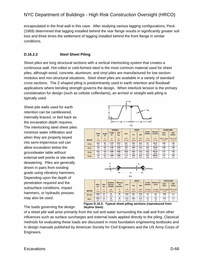
NYC Department of Buildings - High Risk Construction Oversight (HRCO)
Excavations D-68
encapsulated in the final wall in this case. After studying various lagging configurations, Peck (1969) determined that lagging installed behind the rear flange results in significantly greater soil loss and three times the settlement of lagging installed behind the front flange in similar conditions.
D.16.2.2 Steel Sheet Piling Sheet piles are long structural sections with a vertical interlocking system that creates a continuous wall. Hot-rolled or cold-formed steel is the most common material used for sheet piles, although wood, concrete, aluminum, and vinyl piles are manufactured for low section-modulus and non-structural situations. Steel sheet piles are available in a variety of standard cross sections. The Z-shaped piling is predominantly used in earth retention and floodwall applications where bending strength governs the design. When interlock tension is the primary consideration for design (such as cellular cofferdams), an arched or straight web piling is typically used.
Sheet pile walls used for earth retention can be cantilevered, internally braced, or tied back as the excavation depth requires. The interlocking steel sheet piles minimize water infiltration and when they are properly keyed into semi-impervious soil can allow excavation below the groundwater table without external well points or site-wide dewatering. Piles are generally driven in pairs from existing grade using vibratory hammers. Depending upon the depth of penetration required and the subsurface conditions, impact hammers, or hydraulic presses may also be used.
The loads governing the design of a sheet pile wall arise primarily from the soil and water surrounding the wall and from other influences such as surface surcharges and external loads applied directly to the piling. Classical methods for evaluating these loads are discussed in most foundation engineering textbooks and in design manuals published by American Society for Civil Engineers and the US Army Corps of Engineers.
Figure D.16.3: Typical sheet piling sections (reproduced from Skyline Steel)

NYC Department of Buildings - High Risk Construction Oversight (HRCO)
Excavations D-69
D.16.2.3 Contiguous Bored Piling (Secant and Tangent Piles) Continuous walls can be formed by installing a row of cast-in-place piles at a narrow spacing. If the spacing is equivalent to the pile diameter the wall is said to be tangent. In practice, tangent pile walls suffer from gaps between piles and they are generally not considered to be waterproof. Post-excavation repairs and external grouting are often required.
Secant pile walls are constructed by boring primary piles at an on-center spacing that is slightly less than twice the nominal pile diameter. Before the concrete in the primary piles achieves its full design strength, secondary piles are bored between them. As the secondary pile is advanced, the auger or cutting head carves a secant from each of the primary piles to form an interlocking continuous wall. To improve the bending capacity of the circular section, piles are reinforced. For long piles or high-section modulus applications, longitudinal steel is replaced by steel beam sections. Tiebacks or rock anchors can be installed through unreinforced secondary piles or the wall can be internally braced as the excavation depth requires.
When properly designed for bearing, secant pile walls can serve as the permanent earth retention system and the perimeter foundation for the final structure. A unique application is the procedure of top-down construction. In this system, the perimeter walls (and interior foundation if applicable) are installed first from existing grade, then the interior is excavated in stages to the design subgrade floor level. As each level is reached, the floor and its associated support system is constructed and the excavation proceeds as a mining operation to the next stage. The finished floor provides the lateral bracing to support the perimeter as the operation proceeds. Depending upon the nature of the construction and the foundation system used to support the interior column loads, construction can proceed upwards and downwards simultaneously.
D.16.2.4 Diaphragm (Slurry) Walls Reinforced concrete diaphragm walls are constructed by mechanical excavation of a slurry-supported trench. Initially a set of concrete guide walls are constructed on the ground surface along the trench alignment. A hydraulic clamshell-type grab suspended from a cable crane or
Figure D.16.4: Secant piles being installed using segmental casing

NYC Department of Buildings - High Risk Construction Oversight (HRCO)
Excavations D-70
specialized carrier rig is then used to excavate to the desired depth in segmental panels. The trench is kept filled with a viscous slurry (usually a mixture of bentonite or a polymer, sand, and water) to prevent collapse during excavation. After the slurry is de-sanded, a reinforcing cage is lowered into the excavation, and the slurry is displaced by tremie-placed concrete. In modern systems the slurry is pumped from the excavation as it is displaced and recycled.
The economy of slurry walls is derived from their dual use as temporary and permanent earth retention systems. Tiebacks and internal bracing (or top-down construction as described above) can be used to support diaphragm walls as necessary. Because they are excavated in panels, diaphragm walls are subject to the same problems of end gaps and water leakage as tangent pile walls. Moreover, because inspection under slurry is difficult, inclusions of spoil or partial cave-in may result in “windowing” of the panels.
As equipment has improved, production rates increased, and costs have been reduced, secant pile walls have assumed a greater market share of mid-depth to deep construction. Diaphragm walls are largely limited to deep construction with relatively long wall alignments. The recirculation tanks, material storage, and reinforcing cage assembly areas require considerable amounts of laydown area. Often a dedicated service crane must be provided in addition to the slurry rig.
D.16.2.5 Ground Modification (Soil Nailing) Soil nailing is an in-situ technique for reinforcing, stabilizing and retaining excavations and deep cuts through the introduction of relatively small, closely spaced inclusions (usually steel bars) into a soil mass, the face of which is then locally stabilized. A zone of reinforced ground is formed that functions as a soil retention system.
Figure D.16.5: Slurry wall rig with hydraulic grab

NYC Department of Buildings - High Risk Construction Oversight (HRCO)
Excavations D-71
The typical construction sequence begins with the excavation of a shallow cut. Then shotcrete is applied to the face of the cut and soil nails are drilled and grouted. This sequence is then repeated until subgrade is reached.
Soil nailing is possible in a wide range of materials including clays, sandy soils, weathered rock, and tallus slope deposits. Depending upon the individual layer strengths and thicknesses soil nailing can also be effective at retaining heterogeneous and stratified soils. Soil nailing is not practical in soft plastic clays, loose organic and peat deposits, and low density soils. Fills (rubble, cinder, ash, etc.) and soils below the water table are generally not suitable for soil nailing.
D.16.3 Underpinning Underpinning is the transfer of the foundation loads of an existing structure to alternative supports such as cast-in-place concrete pits or piers, push piles or micropiles, or it may consist of a ground modification technique such as jet grouting. The actual system chosen will be dependent upon the size and integrity of the existing foundations and the required capacity. Prestressing of the installed components enables the underpinning system to provide active support and limit the potential of settlement related damage.
In most cases, the underpinning is a permanent change to the foundation of an existing building. The construction of the underpinning will result in the redistribution of loads throughout the structure either temporarily or permanently. Reinforcement of existing foundations, structural ties, or repairs within the building, may be required to stabilize the structure before underpinning work begins.
D.16.3.1 Classical Underpinning In its simplest form, underpinning consists of excavating rectangular pits or piers at regularly spaced intervals beneath an existing bearing wall or strip foundation. The pits are filled with concrete or brickwork up to within 2 to 4 inches of the underside of the existing foundation. After the new work has been allowed to set and shrink, the gap is dry-packed with mortar or rammed with steel shims to make full contact with the existing foundation. The process is repeated on the intervening segments to form a continuous strip of underpinning. Because of
Figure D.16.6: Application of shotcrete over wire mesh for a soil nail wall (Hayward Baker, Inc.)

NYC Department of Buildings - High Risk Construction Oversight (HRCO)
Excavations D-72
the significant risk of soil loss associated with excavations below the water table, the method is basically limited to dry ground.
Tomlinson (1995) states that the maximum length of unsupported wall above the pit excavations should not exceed 4 to 5 feet for brick walls of normal construction. The unsupported lengths should be equally distributed over the length of the wall, and in no circumstances should the sum of the unsupported lengths exceed one-quarter of the total length of the structure. If the wall is heavily loaded or shows signs of structural weakness, the unsupported length should not be allowed to exceed one-fifth to one-sixth of its total length. Exceptionally wide foundations should be underpinned in steps working from back to front.
Winterkorn and Fang (1975) indicate that large column footings can be underpinned in multiple pits, but they recommend that no more than 20% of the footing support be underpinned at any one time without shoring the columns. They indicate that the most common error is to extend the underpinning to just below the subgrade of the excavation of the planned structure instead
of founding the underpinning on a suitable bearing stratum. The extent and success of underpinning are dependent upon the care taken in other phases of the work such as the lateral bracing of the underpinning, general excavation techniques, sheeting of the excavation, and the groundwater pumping methods used on the project.
Smoltczyk (2003) states that bearing capacity and settlement considerations should be used to determine the size and sequence of underpinning. Because the buildings loads will be
Figure D.16.7: Conventional pit underpinning (reproduced from Winterkorn and Fang)

NYC Department of Buildings - High Risk Construction Oversight (HRCO)
Excavations D-73
transferred to adjacent unexcavated areas, the sequence of underpinning should start at the wall sections with the highest loads so as to minimize the potential for differential settlement between pit locations. For weak or old structures, Smoltczyk recommends starting the underpinning at the corners to provide fixed support conditions at the edges of the section then moving to the center to provide a midspan support. If the work begins at the center and then moves outward, a “saddle” support condition can result which can cause vertical cracking.
D.16.3.2 Push Piles or Resistance Piers A push pile typically consists of a structural steel pile (or pier) installed to bedrock or other suitable bearing stratum which is attached to the foundation or slab through a head assembly. In most applications, the push pile will be driven hydraulically to the design resistance using the existing structure as a reaction. In cases where the underpinning is intended to recover settlement, the structure can then be lifted hydraulically against the load bearing pile to restore it to a higher elevation. The piles are sectional, and can, therefore, be installed in limited access and low overhead conditions.
Depending upon the condition and integrity of the foundation wall of the existing building, it may be necessary to cast a reinforced concrete grade beam adjacent to the structure to provide a suitable connection for the push pile hardware. Dowels should be provided between the grade beam and the existing structure to resist shear forces and to transfer moments which will be created by the eccentric support. The effect of eccentricity on the axial pile capacity should also be considered in the pile design.
D.16.3.3 Drilled-in-Place Micropiles As an alternative to push piles, or if it is determined that structural loads exceed the available working capacity of standard push piles, drilled-in-place micropiles can be used to support the existing building. Micropiles consist of small diameter (typically less than 10-inch diameter) high-strength steel pipe casing with flush couple threaded joints. The piles are normally advanced by duplex drilling techniques using water as the drilling fluid. Sacrificial tricone bits are used to socket the pile into bedrock. After reaching the design depth, the casing interior is
Figure D.16.8: Manifold jacking of push piles to underpin a bearing wall (Reproduced from Atlas Systems Technical Guide for Underpinning Settled Structures, 2003)

NYC Department of Buildings - High Risk Construction Oversight (HRCO)
Excavations D-74
tremie filled and pressure grouted through the equipment with neat cement grout. Because the casing is segmental, micropiles can be installed in low-overhead conditions and in areas inaccessible to standard piling rigs.
The size of the micropiles will be a function of the foundation loads for the existing building, as well as the desired spacing between piles. Due to the size of the head assembly and the casing support frame, micropiles cannot realistically be installed closer than about 16 inches from the wall of an existing building. Therefore, a reinforced concrete grade beam as discussed above for push piles may be required if micropiles are used to underpin the structure.
D.16.3.4 Jet Grouting Jet grouting is a ground modification system which creates in-situ cemented geometries of soil (or soilcrete). Grout is pumped through a rotating rod from which it exits at a high velocity. The energy of the grout jet erodes the surrounding soil which mixes with the grout to create the desired in-place geometry. Full and partial columns as well as panels are possible through control of the rod rotation and withdrawal. Depending upon the geometry desired and the soil conditions, the grout jet can be supplemented with high pressure air or water jets. Because the point of application and the finished geometry are controlled, jet grouting can provide both direct underpinning support of an existing building and a continuous retention system for excavation.
Figure D.16.9: Drilled-in-place micropile installation (Hayward Baker, Inc.)
Figure D.16.10: Jet grout underpinning (Nicholson Construction Company)

NYC Department of Buildings - High Risk Construction Oversight (HRCO)
Excavations D-75
D.17 REFERENCES Boscardin M. and Cording E., “Building Settlement to Excavation Induced Settlement,” ASCE Journal of Geotechnical Engineering, 115, No. 1, January 1989. Boone S.J., “Assessing Construction and Settlement-Induced Building Damage: a Return to Fundamental Principles,” Proceedings Underground Construction, Institution of Mining and Metallurgy, London, 2001. City of Toronto By-Law No. 514-2008 “Building Construction and Demolition, with respect to regulation of vibrations from construction activity,” Council of the City of Toronto, 2008. Clough G.W. and O’Rourke T.D., “Construction Induced Movements of In-Situ Walls,” Proceedings Design and Performance of Earth Retaining Structures, ASCE Special Publication 15, Cornell University, 1989. Curtin W.G. et al., Structural Foundation Designers’ Manual, Blackwell Publishing, Oxford, 2006. Das B.M., Principles of Foundation Engineering, PWS-Kent, Boston, 1990. Design Manual 7.2. Foundations and Earth Structures, US Navy, Washington, DC, 1982. DIN 4123: 2000-9 Deutsche Norm “Excavation, Foundation and Underpinning Work Adjacent to Existing Buildings,” Unterfangungen of the Normenausschuss Bauwesen (Building and Civil Engineering Standards Committee), Berlin, 2000. District of Columbia Construction Codes Supplement of 2008 DCMR 12A Building Code Supplement, “Section 3307A Protection of Adjoining Property,” Washington DC, 2008. Dowding C.H., Construction Vibrations, Northwestern University, 2000. Gratacap L.P., Geology of the City of New York (1909), Kessinger Publishing Co., Reprint 2008. Holtz R. and Kovacs W., An Introduction to Geotechnical Engineering, Prentice-Hall, Englewood Cliffs, New Jersey, 1981. Lavis F., The New York Rapid Transit Railway Extensions, Engineering News, 72, No. 14, October 1, 1914. New York City Transit Authority, Engineering Department, Civil Engineering and Architectural Division, Field Design Standards, unknown. O’Rourke T.D. et al., The Ground Movements Related to Braced Excavations and Their Influence on Adjacent Buildings, US Department of Transportation, 1976, DOT-TST76, T-23. O’Rourke, T.D., “Base Stability and Ground Movement Prediction for Excavations in Soft Clay,” ASCE Journal of Geotechnical Engineering, 122, No. 6, 1996. O’Rourke, T.D., “Ground Movements Caused by Braced Excavations,” ASCE Journal of Geotechnical Engineering, 107, September, 1981, (discussion 109, March 1983).

NYC Department of Buildings - High Risk Construction Oversight (HRCO)
Excavations D-76
OSHA Technical Manual Section V: Chapter 1, Demolition, Washington DC. OSHA Technical Manual Section V: Chapter 2, Excavations: Hazard Recognition in Trenching and Shoring, Washington DC. Peck R.B., “Deep Excavations and Tunneling in Soft Ground,” Proceedings of the 7th International Conference S.M.F.E., Mexico City, 1969, State of the art volume, Sociedad de Mexicana de Suelos, Mexico City, 1969. Puller M., Deep Excavations: a Practice Manual, Thomas Telford Ltd., London, 2003. Regulatory Review of 29 CFR 1926, Subpart P: Excavations, Occupational Safety and Health Administration, Washington DC, March 2007. Report No. FHWA-RD-75-(128 to 130) Lateral Support Systems and Underpinning, Federal Highway Administration, Washington DC, April 1976. Schuberth C.J., The Geology of New York City and Environs, Natural history Press, Garden City, NY, 1968. Smoltczyk U., Geotechnical Engineering Handbook Volume 2: Procedures, Ernst & Sohn, Berlin, 2003. Sowers G.B. and Sowers G.F., “Failures of Bulkhead and Excavation Bracing,” Civil Engineering, 1967, 107, No. 1. Standard Specifications for Highway Bridges, AASHTO, Washington DC, 2002. Statutory Instrument 1994 No. 3140 “The Construction (Design and Management) Regulations 1994,” UK Department of Employment, London,1994. The Party Wall etc. Act 1996, HMSO, London, 1996. Title 29 of the Code of Federal Regulations (CFR) Part 1926, US Government Printing Office, Pittsburgh, PA, 1926. (aka. 29 CFR 1926, Subpart P. Excavations.) Tomlinson M., Foundation Design and Construction, Longman Scientific & Technical, London 1995. Winterkorn H. and Fang H., Foundation Engineering Handbook, Van Norstrand Reinhold Co., New York, 1975.

NYC Department of Buildings - High Risk Construction Oversight (HRCO)
Excavations D-77

HRCO: Benchmarking
Benchmarking I-1
I. Regulatory Benchmarking I.1 DESCRIPTION: The benchmarking survey was developed with a goal of obtaining general operational and specific HRCO related information from a wide cross section of large jurisdictions that provide similar building department type services. One of the goals of the HRCO project was to look for gaps in the NYC regulatory framework that can compromise safety, particularly with regard to the potential for major accidents. While the local conditions and needs of every jurisdiction are unique, this survey provides a basis from which best practices worthy of future study can be identified as well as potential gaps in NYC services meriting further investigation.
The survey was developed utilizing input from both the HRCO operational teams and their DOB counterparts. A beta test version of the survey was circulated to three jurisdictions to evaluate the questions prior to wider distribution. The survey was also circulated to DOB subject matter experts for input and changes before being sent out. A constant challenge in the development of the survey was to keep it at a manageable size in order to encourage a representative number of responses. Finally the survey, along with a cover letter, was put into graphical format and distributed.
Big cities are the obvious respondents but in some cases, county departments containing a large city or an urban area with high-rise construction were contacted. For instance, Mecklenberg County, NC contains Charlotte as part of the jurisdiction. Fairfax County, VA has a population of over 1 million with high-rise construction. Pompano Beach served as a beta-test jurisdiction and was chosen because of its waterfront wind exposure and number of concrete high-rise residential projects.
Large cities as well as some county departments, containing a large city or an urban area with high-rise construction, were contacted. The HRCO team received benchmarking surveys from a total of 16 jurisdictions, home to an estimated 26.5 million population (Table I.1).
Table I.1 Population and Construction Data Reported by Responding Benchmarking
Jurisdictions
Jurisdiction Stated
Population
Stated ‘08 Construction
Value Austin, TX 743,074 $1,184,385,825 Boston, MA 600,000 $3,000,000,000 Chicago, IL 3,000,000 n/a Fairfax Co, VA 1,065,178 $1,168,372,000 Honolulu, HI 900,000 $1,917,166,000 Houston, TX 1,954,000 $12,600,000,000 Los Angeles, CA 4,000,000 $4,300,000,000 Mecklenburg Co (Charlotte), NC
1,652,178 $2,713,125,024
Pompano Beach, FL 110,000 $265,000,000 Philadelphia, PA 1,500,000 n/a

HRCO: Benchmarking
Benchmarking I-2
San Diego, CA 1,250,000 $1,430,000,000 San Francisco, CA 800,000 $3,500,000,000 San Jose, CA 1,000,000 $851,113,558 Seattle, WA 800,000 $2,400,000,000 Singapore 4,500,000 $16,000,000,000 Toronto, ON 2,698,400 $6,490,000,000 New York, NY 8,360,000 $33,800,000,000
A number of the jurisdiction responses above referred to Cal-OSHA, so a copy of the cover page and the Crane and Hoist section was sent to Northern California Cal-OSHA. We received back from their crane unit.
Other jurisdictions that were contacted regarding the survey but have not yet responded include:
• San Antonio, TX • Dade County (Miami), FL • Phoenix, AZ • Atlanta, GA
• Dallas, TX • Clark County (Las Vegas), NV • Jacksonville, FL • Orlando, FL
Finally, ten represented countries of the Inter-jurisdiction Regulatory Collaboration Committee (IRCC) received copies of the survey in March. Thus far, one survey was returned from Singapore. The IRCC is an organization of international jurisdictions that fosters collaboration amongst its members in addressing construction-related regulatory issues.
It is anticipated more of the jurisdictions listed above as well as many of the IRCC countries will respond, including:
• Australia • Austria • England
• China • Spain • Japan

HRCO: Benchmarking
Benchmarking I-3
I.2 SUMMARY OF GENERAL TRENDS AND OBSERVATIONS: Returns from the benchmarking study point out a trend of focusing operations on areas where there are demonstrated issues or problems specific to the locale. For example all four of the California cities, located in high seismic regions, report doing a complete structural plan review. Chicago has a focus on deep foundations as they are located on naturally deep and poor soil conditions requiring special care for foundations supporting most structures. New York, Chicago and Philadelphia, all with a dense and a vertical downtown building environment, have a specific crane unit to provide an extra level of safety and enforcement. The Excavations Unit in New York is also an example of services in response to the issue of building collapses and adjacent property structure damage.
Because New York has a relatively benign natural environment (low seismicity, solid bedrock and low incidence of tropical wind events) there is no recent history of natural events driving the focus on plan review and structural inspections. Instead, there has been a history of crane and construction accidents which has focused attention on areas such as site safety and means and methods of construction. These are not typically perceived by many as the primary mission for building departments. This alternative focus can compete for resources with areas of work normally viewed by many building departments as their core work: structural plan review and inspections to ensure public safety of the built environment. One of the goals of the survey was to determine the level of focus on site safety and means and methods type of work in other regions and that relationship to other activities performed by individual jurisdictions.
Most survey responses reveal that site safety inspections, when performed, are typically an offshoot of departments’ day-to-day construction progress inspections and are rarely accomplished by stand-alone site safety inspections. The benchmarking effort also shows there are very few major building departments who do not complete some sort of structural plan review and do not perform structural inspections.
Table I.2 presents a summary of benchmarking information related to study areas documented in the HRCO report. For each area the survey results are compared and contrasted to New York.
Table I.2 Benchmarking Summary
Study Area Benchmarking Jurisdictions New York City Structural Plan Review
14 out of 16 responding building departments perform detailed or partial structural plan review on major projects.
Relies on the professional for code compliance of structural drawings
Excavation and Underpinning
11 out of 14 respondents require either a partial or detailed structural plan review of excavation, permanent earth retention systems and/or underpinning.
Selective audits are performed
Special Inspections 13 out of 15 respondents qualify special inspection agencies in one of three ways: themselves, rely on some
DOB established qualifications for special inspection agencies

HRCO: Benchmarking
Benchmarking I-4
Study Area Benchmarking Jurisdictions New York City form of qualification process, or accept International Accreditation Service Inc. (IAS) accreditation.
effective July1, 2008, and requires accreditation by IAS or other nationally recognized accrediting bodies by July 1, 2010.
7 out of 9 responding jurisdictions require the special inspection agency to notify the building of an observed ongoing, unresolved, construction deficiency.
The 2008 NYC Building Code requires hazardous conditions be reported to the Department.
11 out of 15 responding jurisdictions either perform structural inspections with their staff in addition to special inspections or provide QA/QC of the special inspections with their staff on a proactive basis for major projects.
Structural inspections are not performed.
The fastest number of days from floor to floor from six initial responding jurisdictions was 3 days on average for high-rise concrete with the typical floor to floor cycle of 5 to 7 days according to 4 initial responding jurisdictions.
The two to three day cycle is common in NYC.
Rebar is typically fabricated in the shop at all 8 responding jurisdictions.
Majority of reinforcement in NYC is bent on-site; current union rules prohibit shop fabrication of reinforcement, and while non-union sites do use some shop fabrication, on-site bending is still common there as well.
Concrete and Rebar Practices
14 jurisdictions reported no requirement for wind design of forms or anchorage.
’08 and ’68 code require formwork to be designed to resist wind.
1 of 6 jurisdictions that regulate general site safety on high-rise concrete reported only specific site safety inspections.
’08 and ’68 codes have requirements for site safety on all projects, BEST squad actively enforces on major buildings.
Concrete Regulatory and Safety Practices
2 of 16 responding jurisdictions issue citations for OSHA work place violations on high-rise concrete.
DOB does not have the authority to issue OSHA citations.

HRCO: Benchmarking
Benchmarking I-5
Study Area Benchmarking Jurisdictions New York City 2 of 13 responding jurisdictions license or regulate site safety managers.
DOB licenses site safety managers and site safety coordinators.
5 out of 15 responding building departments regulate tower cranes, and 3 out of 15 regulate mobile cranes other than relying on the state or federal OSHA.
Both tower cranes and mobile cranes are regulated.
One jurisdiction reported having a requirement for tower crane part inventory and tracking of parts for jumps or during dismantling.
New requirements are being developed.
Two building department respondents issue licenses or otherwise regulate crane operators.
Operators are licensed.
Crane Practices
Cal-OSHA has a rule or policy for synthetic rigging material stating it is “allowed” and Singapore (MOM) states synthetic sling materials are statutory lifting gear.
The use of synthetic slings is prohibited by law for tower crane assembly, jumping, and disassembly unless required by the manufacturer.
No jurisdictions reported regulating crane signal persons or pedestrian safety flag persons.
This is under consideration with the new code, licensing of crane safety coordinator and signal person.
Singapore was the only jurisdiction out of 15 that reported they have a program for targeted focus of plan review or inspections where the license holder has a history of repeated violations or incidents.
DOB has a targeted audit program in place.
Regulation and Licensing Practices
Only Singapore reported keeping a database on the number and type of construction accidents.
DOB maintains a construction incident database

HRCO: Benchmarking
Benchmarking I-6
I.3 HRCO BENCHMARKING DATA OBSERVATIONS:
I.3.1 Structural Plan Review Practices
As seen in Figure I.1, the majority of jurisdictions surveyed perform some form of detailed or partial structural plan review on major projects. New York City relies on the professional for code compliance of structural drawings.
Figure I.1 Jurisdictions Performing Some Structural Plan Review
* Results out of 16 jurisdictions
The depth of review appears to be geographically based on perceived risk, local conditions or state law. For example all four jurisdictions responding in California reported 100% of major jobs receive a detailed structural plan review. San Francisco has an additional peer review process for major structures. Other areas with less perceived earthquake risk do more or less of a focused or spot check structural review based on the degree of completeness of the construction documents and the relative risk of the project. Chicago reported reviewing 99% of major projects with a detailed structural review and because foundation designs are challenging due to deep and poor soils, there is a great emphasis on proactive plan review of deep foundations. Only the two jurisdictions located in Texas rely solely on self certification by design professionals for major projects. Alternatively, Austin does a structural review of plans for buildings under 5000 square feet that are not prepared by a design professional.
Singapore utilizes extensive third party review by accredited checkers who are registered professional engineers licensed by the building department. The building department itself also completes audits of all submissions and a focused plan review on 20% of the submissions. Self certification is utilized for minor work but these projects still receive a focused review from the department on at least 20% of all submittals.
Jurisdictions with partial or focused plan review utilizing guidelines to determine the focus of plan review include: Mecklenburg County, Pompano Beach, Seattle and

HRCO: Benchmarking
Benchmarking I-7
Toronto. These jurisdictions may be worthy of additional investigation to glean ideas and best practices used to prioritize the focus of limited plan review resources. Boston utilizes an affidavit for structural plan review applications and/or peer review to provide review and accountability for submitted plans. Chicago is working on a self certification policy to augment its capacity and expressed interest to work with DOB on the development of a sound and flexible program and standard operating procedure to create a QA/QC audit process for self certifications of plan review.
Mecklenburg County reports only 10% of projects receive a focused or partial structural review while 90% of projects are self certified. The engineer of record for the overall project completes, stamps and signs a summary of the design loads and calculations in a pre-determined format provided by the jurisdiction. All of these documents are given a cursory review by the jurisdiction and compared with the submitted structural construction documents. Based on this review, certain projects with higher risk (high-rise) and other projects with missing documents or issues are targeted for additional review. This makes up the 10% reported with a focused or partial structural review.
Fairfax County, VA reported doing a one hour spot check for major structures. The one review is a cursory check of vertical loads, importance factor, and the wind and seismic loads applied. The jurisdiction also utilizes a peer review process to conduct additional assessments. A more detailed review is performed on smaller projects with a wider array of design engineers and competency levels.
All of the systems mentioned to screen projects and prioritize structural plan review effort deserve additional study as a tool to effectively require more focused structural plan review on appropriate projects while managing the resources needed for the program.
Many jurisdictions mentioned also utilize a collection of resources or strategies to make plan review scalable and stated they have a fast track plan review process. Given the variable nature of construction volume, a challenge for both large and small building departments is to build a scalable system to provide consistent quality service regardless of the level of workload. Many respondent jurisdictions use a combination of jurisdiction staff, self certification, peer review, third party review hired by owners, and consultants hired by the jurisdiction to help balance available resources with varying workload as needed to maintain service levels. This challenge must be met to be effective and sustainable in the long term with any service as work levels tend to fluctuate. The issuance of Directive No. 2 of 1975 ceased almost all structural plan review to date (not including excavation design audits, as discussed below). Thus any level of structural screening or plan review should be investigated as an improvement. A positive first step is the requirement for peer review recently adopted in section 1627 of the 2008 New York City Building Code. However, buildings covered by Section 1627 represent only a small slice of the overall built environment.
Benchmarking results show various versions of four basic steps that can be implemented incrementally to provide a comprehensive structural plan review program:
1. Develop a system and criteria to screen all submitted projects.
2. Define and prioritize the level of self certification, QA/QC, independent structural plan review and/or peer review based on rational criteria.
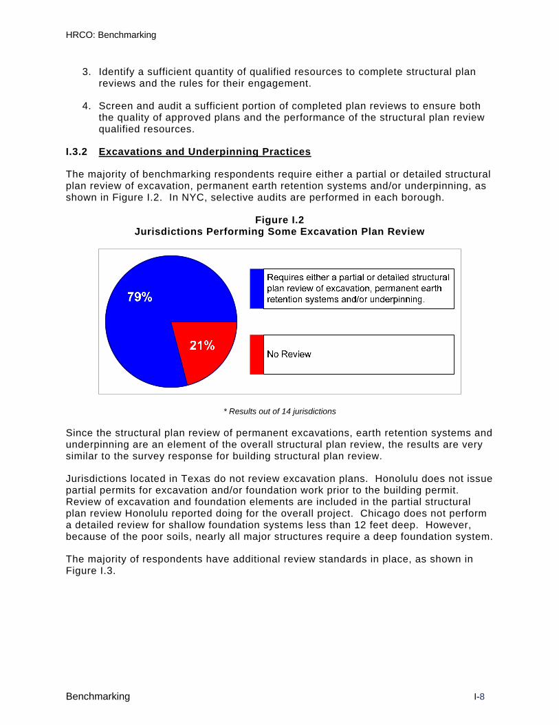
HRCO: Benchmarking
Benchmarking I-8
3. Identify a sufficient quantity of qualified resources to complete structural plan reviews and the rules for their engagement.
4. Screen and audit a sufficient portion of completed plan reviews to ensure both the quality of approved plans and the performance of the structural plan review qualified resources.
I.3.2 Excavations and Underpinning Practices
The majority of benchmarking respondents require either a partial or detailed structural plan review of excavation, permanent earth retention systems and/or underpinning, as shown in Figure I.2. In NYC, selective audits are performed in each borough.
Figure I.2 Jurisdictions Performing Some Excavation Plan Review
* Results out of 14 jurisdictions
Since the structural plan review of permanent excavations, earth retention systems and underpinning are an element of the overall structural plan review, the results are very similar to the survey response for building structural plan review.
Jurisdictions located in Texas do not review excavation plans. Honolulu does not issue partial permits for excavation and/or foundation work prior to the building permit. Review of excavation and foundation elements are included in the partial structural plan review Honolulu reported doing for the overall project. Chicago does not perform a detailed review for shallow foundation systems less than 12 feet deep. However, because of the poor soils, nearly all major structures require a deep foundation system.
The majority of respondents have additional review standards in place, as shown in Figure I.3.

HRCO: Benchmarking
Benchmarking I-9
Figure I.3 Additional Excavation Review Procedures
Complete some form of
plan review for
temporary earth
retention systems
Minimum submittal
standards
Require either a soils
investigation with
multiple probes or test
pits
Require geotechnical
engineer to review
plans for main structure
Geotechnical engineer
to review underpinning
or excavation plans
The breakdown of responses in the figure above is as follows:
• 9 out of 15 respondents complete some form of plan review for temporary earth retention systems.
• 7 out of 15 respondents have minimum submittal standards. Boston is in the process of developing a policy for minimum submittal requirements, Chicago, Fairfax County, Honolulu, Los Angeles, Philadelphia, San Francisco and Singapore all reported having minimum submittal requirements.
• 9 out of 15 respondents require either a soils investigation with multiple probes or test pits when underpinning is anticipated for adjacent structures or the original plans for the adjacent building are not available.
• 10 out of 15 respondents require the soils or geotechnical engineer to review plans for the main structure in all or some cases to verify on writing the recommendations of their soils report are incorporated prior to permit issuance.
• 8 out of 14 respondents require the soils or geotechnical engineer to also review underpinning, excavation and/or excavation plans in all or some cases. Jurisdictions requiring evaluation and/or monitoring of adjacent structures include: Boston, Chicago, Philadelphia, San Diego, Seattle, Singapore and Toronto. Toronto recently developed and published specific rules and submittal requirements for the evaluation of vibration influence and monitoring on influenced structures. Singapore requires instrumentation and monitoring by the Engineer of Record along with the requirement for notification of the jurisdiction when a predetermined level of movement in existing structures is exceeded.

HRCO: Benchmarking
Benchmarking I-10
New York City has created an excavations unit that does conduct plan review via selective audits. The excavations unit will perform pro-active reviews if requested by an applicant. Otherwise, the structural review comes post-inspection, when an inspector has identified a serious problem in the field and makes the referral to the engineering unit for review. While this is an interim step towards creating a more comprehensive program, there is considerable room for improvement as demonstrated in benchmarked jurisdictions. This could include making the program proactive with specific plan submittal requirements for excavations, underpinning, reinforcement of existing buildings if applicable, and monitoring of influenced structures. In addition the four steps previously outlined for the establishment of a building structural plan review program could be utilized along with related recommendations made by the HRCO.
I.3.3 Special Inspection and Structural Inspection Practices
I.3.3.1 Special Inspections
As shown in Figure I.4, most respondents qualify special inspection agencies themselves, rely on some other form of qualification process, or accept International Accreditation Service Inc. (IAS) accreditation. DOB established qualifications for special inspection agencies effective July 1, 2008, and requires accreditation by IAS or other nationally recognized accrediting bodies by July 1, 2010.
Figure I.4 Special Inspections Qualification
DOB established qualifications for special inspection agencies effective July 1, 2008, and requires accreditation by IAS or other nationally recognized accrediting bodies by July 1, 2010. Of these jurisdictions, all with the exception of Houston have a special inspection disciplinary process.
Of the seven jurisdictions who responded to the question, the disciplinary process is used on average from zero to two times per year. San Francisco, San Jose and Seattle participate in collective regional qualification efforts worthy of additional follow-up.
When non-conforming work is not resolved quickly, 7 out of 9 responding jurisdictions have a requirement for the special inspection agency to notify the building department

HRCO: Benchmarking
Benchmarking I-11
regarding the observed ongoing construction deficiency. The 2008 NYC Building Code requires that hazardous conditions be reported to the Department.
I.3.3.2 Structural Inspections
As shown in Figure I.5, most jurisdictions either perform structural inspections with their staff in addition to special inspections or provide QA/QC of the special inspections with their staff on a proactive basis for major projects. Most also require some minimum form of certification for their in-house structural inspectors (typically either ICC or state required certifications). Structural inspections are not performed by DOB.
Figure I.5 Minimum Certification for In-House Structural Inspectors
* Results out of 15 jurisdictions
* Results out of 13 jurisdictions
Austin and Houston do not provide structural inspections for major projects. Boston and Honolulu require inspections by the engineer of record in addition to special inspections. Six jurisdictions reported having a qualification process if inspectors outside of the department are used. This is reported to be accomplished by state
HRCO: Benchmarking
Benchmarking I-12
certifications, utilization of special inspection qualification requirements or the engineer of record to engage outside inspectors.
It is clear from the benchmarking results that regular structural progress inspections provide a mechanism for quality control of delegated special inspections and also provide an informal means to help monitor site safety. This appears to be true even when they are minimally performed as an audit or spot check by competent jurisdiction staff,
Judging from other jurisdictions, New York City can substantially improve the effectiveness of its operations in structural and special inspections with aggressive training and recruitment programs aimed at increasing the critical mass of engineers and inspectors with a high level of structural design and inspection knowledge and certification.
Benchmarking shows that as the percentage of staff resources with appropriate training and certification increases, a transition can occur from (1) initially auditing outside inspectors to (2) performing routine spot checks of projects and finally, (3) utilizing DOB staff to perform scheduled audit inspections at critical stages of prioritized projects.
I.3.4 High Rise Concrete Forming and Rebar Practices
I.3.4.1 Cycle Times
The most notable differences in high-rise concrete construction practices were the average number of construction days from floor to floor and the practice of site-fabricated rebar. Cycles times are summarized in Figure I.6.
Rebar is typically fabricated in the shop at all 8 responding jurisdictions. San Francisco estimated 20% of the rebar is site fabricated for buildings of 10 stories or less. Otherwise no other answer showed less than 90% of the rebar being fabricated in the shop. For buildings greater than 10 stories the reported median percent of shop fabricated rebar was 99%.
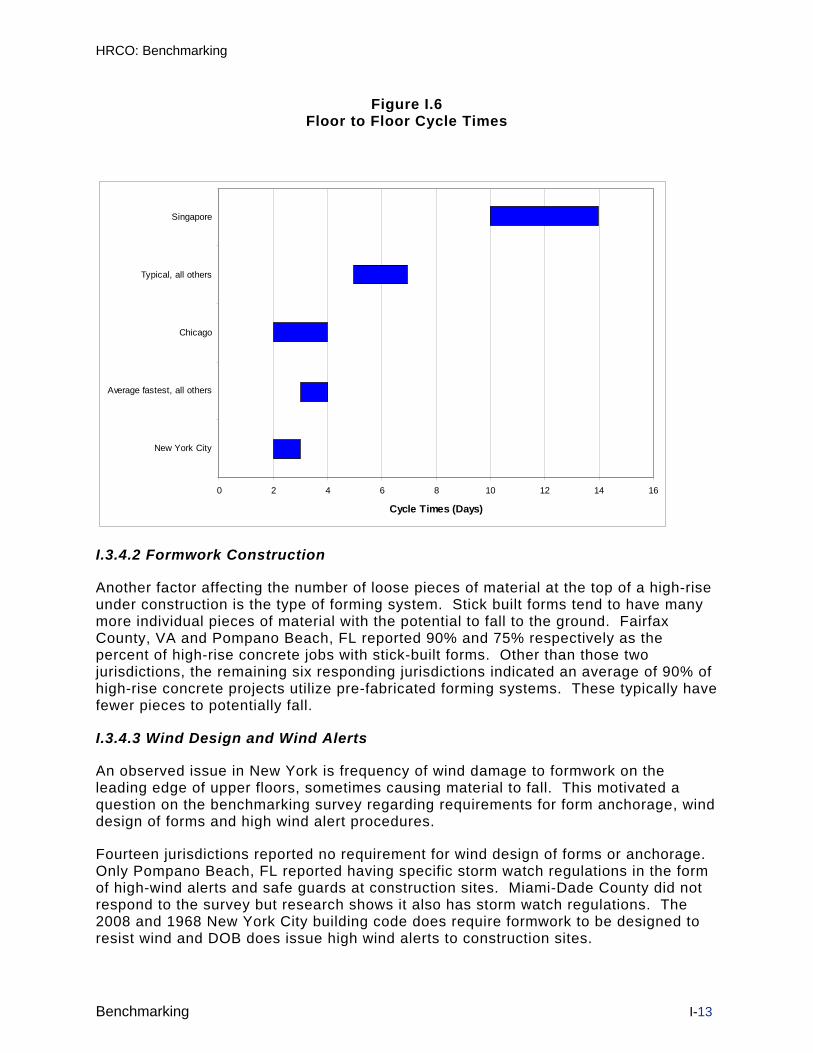
HRCO: Benchmarking
Benchmarking I-13
Figure I.6 Floor to Floor Cycle Times
0 2 4 6 8 10 12 14 16
New York City
Average fastest, all others
Chicago
Typical, all others
Singapore
Cycle Times (Days)
I.3.4.2 Formwork Construction
Another factor affecting the number of loose pieces of material at the top of a high-rise under construction is the type of forming system. Stick built forms tend to have many more individual pieces of material with the potential to fall to the ground. Fairfax County, VA and Pompano Beach, FL reported 90% and 75% respectively as the percent of high-rise concrete jobs with stick-built forms. Other than those two jurisdictions, the remaining six responding jurisdictions indicated an average of 90% of high-rise concrete projects utilize pre-fabricated forming systems. These typically have fewer pieces to potentially fall.
I.3.4.3 Wind Design and Wind Alerts
An observed issue in New York is frequency of wind damage to formwork on the leading edge of upper floors, sometimes causing material to fall. This motivated a question on the benchmarking survey regarding requirements for form anchorage, wind design of forms and high wind alert procedures.
Fourteen jurisdictions reported no requirement for wind design of forms or anchorage. Only Pompano Beach, FL reported having specific storm watch regulations in the form of high-wind alerts and safe guards at construction sites. Miami-Dade County did not respond to the survey but research shows it also has storm watch regulations. The 2008 and 1968 New York City building code does require formwork to be designed to resist wind and DOB does issue high wind alerts to construction sites.

HRCO: Benchmarking
Benchmarking I-14
I.3.4.4 Form Design
Only Fairfax County, VA, Pompano Beach (the same two jurisdictions reporting a large use of stick built forms) and Philadelphia reported requiring engineered design of forms or regulations for form design. Fairfax County, VA requires the engineered design of forms for walls or columns 10’ high or greater. Fairfax County and Philadelphia reported performing plan review of forms while a total of 6 jurisdictions reported performing inspections of forms.
New York high-rise concrete construction practices include three high risk factors:
• a high reliance on stick built forms,
• and site fabricated rebar
• a quick floor cycle
This practice has the resulting outcome of a high number of workers and loose pieces of material at the top of large high-rise concrete projects. Nowhere else could benchmarking efforts duplicate all of these factors. Personnel from other jurisdictions expressed verbal concerns about the quality of site fabricated rebar. Quality issues have also been consistent with field observations by the HRCO team in New York City. Improved practices including QA/QC of structural plan review for engineered forms, special inspections of rebar fabrication and placement, and inspections of formwork particularly at leading edges exposed to wind can all contribute to the performance and safety of high-rise reinforced concrete construction.
I.3.5 Site Safety and Enforcement Practices
I.3.5.1 High Rise Concrete Regulatory and Safety Practices
Figure I.7 shows the areas that responding jurisdictions said they regulate for high-rise concrete or other major projects.

HRCO: Benchmarking
Benchmarking I-15
Figure I.7 Areas Regulated by Responding Jurisdictions
0 2 4 6 8 10 12 14
Regulate structural plan review
Regulate structural inspection
Regulate special inspection agency qualification
Regulate special inspection agency QA/QC
Regulate structural observations required by IBC
Regulate excavation and underpinning plan review
Regulate excavation and underpinning inspections
Regulate crane foundations and ties to structure
Regulate hoist, scaffolding and shoring plan reviews
Regulate hoist, scaffolding and shoring inspections
Regulate general site safety plan reviews
Regulate general site safety inspections
Number of Responding Jurisdictions
Of the six responding jurisdictions that regulate general site safety on high-rise concrete, only Boston reported inspections solely focused on site safety. Three of the remaining five jurisdictions that regulate site safety, conduct site safety inspections as part of their regular structural progress inspections and two do both specific site safety inspections and site safety inspections as part of the regular day to day inspections. Both the 2008 and 1968 NYC codes have requirements for site safety on all projects. DOB actively enforces these requirements on major buildings.
There were a wide variety of ways to resolve general, repeated and immediately dangerous site safety violations. The most popular first response was to write a violation or correction notice. After repeated unresolved site safety violations the most popular response was to refer to OSHA followed by writing a stop work order. The most popular way of resolving an immediately dangerous condition was to write a stop work order. While 8 of 13 responding jurisdictions report coordinating site safety violations with OSHA, only 2 of 16 responding jurisdictions issue some sort of citation for OSHA work place violations on high-rise concrete (San Francisco and Pompano Beach, FL). DOB does not have the authority to issue OSHA citations.
Figure I.8 summarizes site safety manager and worker safety information gathered from responding jurisdictions.

HRCO: Benchmarking
Benchmarking I-16
Figure I.8 Site Safety Practices
1542
Jurisdiction licenses or
registers site safety
manager
Site safety manager is
hired by the contractor
8558
100%
0%
Does not occur in this jurisdiction
Occurs in this jurisdiction
88
12
Jurisdiction had
knowledge of education
programs geared
towards construction
workers
Detail regarding the figure above is as follows:
• 2 of 13 responding jurisdictions license or regulate site safety managers (Singapore through MOM and Fairfax County on large County owned projects). DOB does license site safety managers.
• 7 out of 8 responding jurisdictions stated site safety managers are hired by the contractor. One said they are hired by the owner.
• 5 out of 12 responding jurisdictions reported some knowledge of site safety education programs geared to individual construction workers.
Benchmarking appears to show most jurisdictions focus on what they view as their core area of work: plan review, special inspections and progress inspections of construction. Even on special or major projects, most jurisdictions integrate site safety work into the overall department organization. General site safety inspections, when they occur, tend to be an offshoot of what is perceived as core functions. In New York City, site safety work appears to be the main area of focus in many respects because DOB has a delegated system of structural inspections and a professional certification process.
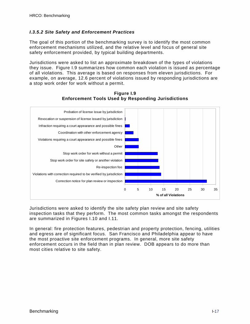
HRCO: Benchmarking
Benchmarking I-17
I.3.5.2 Site Safety and Enforcement Practices
The goal of this portion of the benchmarking survey is to identify the most common enforcement mechanisms utilized, and the relative level and focus of general site safety enforcement provided, by typical building departments.
Jurisdictions were asked to list an approximate breakdown of the types of violations they issue. Figure I.9 summarizes how common each violation is issued as percentage of all violations. This average is based on responses from eleven jurisdictions. For example, on average, 12.6 percent of violations issued by responding jurisdictions are a stop work order for work without a permit.
Figure I.9 Enforcement Tools Used by Responding Jurisdictions
0 5 10 15 20 25 30 35
Correction notice for plan review or inspection
Violations with correction required to be verified by jurisdiction
Re-inspection fee
Stop work order for site safety or another violation
Stop work order for work without a permit
Other
Violations requiring a court appearance and possible fines
Coordination with other enforcement agency
Infraction requiring a court appearance and possible fines
Revocation or suspension of license issued by jurisdiction
Probation of license issue by jurisdiction
% of all Violations
Jurisdictions were asked to identify the site safety plan review and site safety inspection tasks that they perform. The most common tasks amongst the respondents are summarized in Figures I.10 and I.11.
In general: fire protection features, pedestrian and property protection, fencing, utilities and egress are of significant focus. San Francisco and Philadelphia appear to have the most proactive site enforcement programs. In general, more site safety enforcement occurs in the field than in plan review. DOB appears to do more than most cities relative to site safety.

HRCO: Benchmarking
Benchmarking I-18
Figure I.10
Site Safety Site Inspection Tasks
0 1 2 3 4 5 6 7 8 9 10
Pedestrian protection sheds
Building egress and routes
Adjacent property protection
Pedestrian routing and barriers
Construction fencing and gates
Overhead utilities
Underground utilities
Scaffolding erection and use
Site address and complaint phone number
Temporary trench shoring and retaining system
Fire department site access
Fire water supply (standpipe)
Fire access elevators (if over 75 feet )
Material storage and anchorage
Formwork and temporary shoring
Excavation and site egress
Horizontal and vertical safety netting
Personal fall arrest system
Number of Jurisdictions

HRCO: Benchmarking
Benchmarking I-19
Figure I.11 Site Safety Plan Review Tasks
0 1 2 3 4 5 6 7 8 9
Fire department site access
Fire water supply (standpipe)
Fire access elevators (if over 75 feet)
Building egress and routes
Sidewalk and roadway widths
Adjacent property protection
Underground utilities
Number of Jurisdictions
I.3.6 Crane Practices
DOB regulates both tower and mobile cranes to a greater extent than most jurisdictions. As shown in Figure I.12, the majority of responding jurisdictions do not regulate cranes in any manner other than relying on the state or federal OSHA.
Figure I.12 Crane Regulations
33 20Regulate tower
cranes
Regulate
mobile cranes
6780
100%
0%
Jurisdictionsthat do not
Jurisdictions that do

HRCO: Benchmarking
Benchmarking I-20
Of those who do regulate tower cranes:
• In California, Cal-OSHA specifically regulates tower cranes and relies on third party certification for mobile cranes. In Singapore, the Ministry of Manpower (MOM) regulates tower cranes and mobile cranes utilizing authorized examiners for plan review of tower cranes and tests plus inspections by third parties.
• Fairfax County, VA was the only building department requiring tests and inspections by third parties for tower cranes. Chicago was the only building department that provides tests and inspections utilizing their own inspectors for tower cranes.
• Chicago, Fairfax County VA, Singapore (MOM), and San Francisco were the only building departments that issue individual crane permits and/or prototypes for tower cranes. Chicago issues individual permits not prototypes for tower cranes and Fairfax County issues electrical permits for tower cranes. Cal-OSHA issues individual permits and prototypes for tower cranes.
• Austin , Chicago, Cal-OSHA, Fairfax County, Singapore (MOM) and San Francisco all reported requiring plans and calculations by a registered engineer for tower cranes and the jurisdiction performs or requires a plan review.
• Chicago, Cal-OSHA, Fairfax County and San Francisco all require the building engineer of record to review tower crane plans for tie-in points and foundations. Singapore (MOM) requires a PE to review the plans for tie-in points and foundations.
• Chicago, Fairfax County and Cal-OSHA all require special inspections for tower crane tie connections and foundations.
• Chicago, Singapore (MOM) and Cal-OSHA require pre-assembly non-destructive testing for tower cranes. Chicago, Singapore (MOM), Cal-OSHA and Fairfax County require assembled tests and inspections of tower cranes.
• Philadelphia has a requirement for tower crane part inventory and tracking of parts for jumps and during dismantling.
• Philadelphia, Singapore (MOM) and Chicago regulate mobile cranes. Chicago requires plans and calculations by a registered engineer and does a plan review for mobile crane installations that are not at grade.
• Cal-OSHA and Singapore (MOM) both reported having a repair procedure and inspections for tower and mobile crane repairs. Chicago is developing a repair procedure.
A substantial majority of responding jurisdictions do not license crane operators or regulate riggers.

HRCO: Benchmarking
Benchmarking I-21
Figure I.13
Licensing of Crane Operators and Riggers
82 89
License crane
operators
Regulate
riggers
18 11100%
0%
Jurisdictionsthat do not
Jurisdictions that do
Philadelphia and Chicago were the only two building departments out of 11 respondents that issue licenses or otherwise regulate crane operators. Other jurisdictions rely on the state OSHA, federal OSHA or the Ministry of Labor (in the case of Toronto) or the Ministry of Manpower (MOM) (in the case of Singapore).
1 out of 9 responding building departments regulate riggers, Philadelphia was the only building department that requires a license for riggers or master riggers.
DOB licenses both operators and riggers. Other notable crane regulatory information includes:
• 2 out of 14 respondents have a rule or policy regarding synthetic slings. Cal-OSHA has a rule or policy for synthetic rigging material stating it is “allowed” and Singapore (MOM) states synthetic sling materials are statutory lifting gear. NYC passed a law prohibiting the use of synthetic slings for tower crane assembly, jumping, and disassembly. In NYC, the use of synthetic slings is prohibited by law for tower crane assembly, jumping, and disassembly unless required by the manufacturer
• 4 out of 13 respondents have a rule or policy requiring a physical barrier between hoisting areas and pedestrians. Singapore requires a risk assessment. No jurisdictions reported knowledge of any public awareness campaigns for pedestrian safety around crane hoisting areas.
Based upon benchmarking results to date, the New York City crane oversight program has a greater scope than most building departments and enforcement agencies. Cal-OSHA practices for tower cranes may be worthy of additional study. Inspections by Cal-OSHA personnel for tower cranes are in addition to inspections provided by third parties and serve as an extra quality control component for both tower and mobile crane inspections. Additional investigation of Cal-OSHA and Singapore (MOM) repair procedures may be worthwhile study.

HRCO: Benchmarking
Benchmarking I-22
I.3.7 Construction Hoist Practices
As shown in Figure I.14, the majority of respondents do not regulate material or personnel hoists.
Figure I.14 Material and Personnel Hoists Regulations
* Results out of 15 jurisdictions
Additional detail for those respondents that do some level of regulation includes:
• Fairfax County, VA and Houston were the only building departments providing these services. Both require specific tests after initial acceptance and Fairfax County requires or recognizes third party inspectors. Cal-OSHA also regulates construction hoists but does not require specific tests after initial acceptance. Singapore relies on third party inspections.
• Cal-OSHA and Singapore were the only two respondents that record incidents with injury or death due to hoist service personnel riding on the top of the cab during service or installation.
• Cal-OSHA, Singapore and Houston provided contact information on the person in charge of the construction hoist program.
• Of the other jurisdictions responding, Boston and Pompano Beach Florida require the building engineer of record to review plans for the hoist prior to the permit or during erection. Philadelphia requires signoff of the hoist installation by the building engineer of record and/or the hoist engineer of record.
As in cranes, the New York City hoist oversight program has a greater scope than most building departments and enforcement agencies. Additional investigation of jurisdictions utilizing third party inspections and/or signoff required from the engineer of record may be worthwhile. Also, follow-up with jurisdictions where there are reports of death or injury caused by service personnel riding on the cab undertaken since this has been an issue also in New York City.

HRCO: Benchmarking
Benchmarking I-23
I.3.8 Regulation and Licensing Practices
Jurisdictions have many different methods of regulating or issuing licenses for individuals involved in the construction trades. Typically states are the primary regulatory body for contractor and engineer licenses. The scope of this benchmarking study did not go into great detail regarding the relationship and overlap between states and local jurisdictions. However the following observations are noteworthy:
• Only Chicago, Philadelphia, Singapore and San Francisco indicated they regulate permit expediters.
• Philadelphia was the only building department to indicate they regulate third party crane inspectors, riggers or master riggers.
• No jurisdictions reported regulating crane signal persons or pedestrian safety flag persons (Boston reported the local police regulate flag persons). This is under consideration in NYC in conjunction with the new codes.
• Chicago was the only building department that reported regulating hoist operators and none reported regulating hoist inspectors. Singapore (MOM) reported regulating both.
• Singapore was the only jurisdiction out of 15 that reported they have a program for additional plan review or inspections where the license holder has a history of repeated violations or incidents. DOB has a targeted audit program in place.
• Only Boston, Los Angeles and Pompano Beach reported requirements for evidence of fitness for duty for license holders. Chicago is considering it in the future for general contractors
• Pompano Beach refers to state requirements for continuing education. Singapore requires continuing education for engineers and architects.
• Only Singapore keeps a database to track the number and type of construction accidents. DOB maintains a construction incident database.

HRCO: Benchmarking
Benchmarking I-24
I.4 BENCHMARKING DISCUSSION New York City regulates at a greater degree than most building departments when focusing on site safety, cranes and hoists. Still there are measures from other jurisdictions which may be of value.
New York City tends to regulate at a lesser degree than most building departments in the areas of structural plan review, special inspections and structural inspections. This is particularly true with building construction and excavations and underpinning.
The benchmarking study raises the foundational question of DOB’s role. For most other jurisdictions, site safety, when not addressed by OSHA, is dealt with as an adjunct to the core functions of plan review and inspections of construction. The New York City DOB approach is almost polar opposite. This benchmarking study, in conjunction with the HRCO recommendations, should be used as a starting point in answering the important question of the appropriate DOB focus.
Conclusions and statements in this report are made based on interpretation of survey responses, information from the HRCO study and a limited number of follow-up calls. Given the number of areas of study and sometimes incomplete responses, all conclusions and statements should be viewed as starting point for additional follow-up, investigation and verification, particularly where statements are used as a basis to consider future changes in the regulatory process. The NYC Department of Buildings should continue to benchmark with other jurisdictions to obtain information on areas where there may be room for improvement but also share information of its practices where it is taking the lead.

Appendix II
Principal Staff Resumes
Project Management - CTL Steven Smith – Program Director W. Gene Corley – Senior Advisor
High-rise Concrete - CTL Jeffrey Garrett - Principal
David Drengenberg – Field Manager
Cranes – Crane Tech Solutions Manfred Kohler - Principal Frank Hegan – Principal
Marcus Janik – Field Manager
Excavations - AECOM Ted Bushell - Principal
Darren Diehm – Field Manager
Hoists – Patuxent Engineering Group John O’Connor - Principal
Regulatory – DBR Group
Dennis Richardson - Principal
Steven J. Smith
6/2009
STEVEN J. SMITH PRINCIPAL ENGINEER AND GROUP MANAGER
CTLGroup 9030 RED BRANCH ROAD, SUITE 110 COLUMBIA, MD 21045 Phone: 410-997-8480 Fax: 410-997-0400 [email protected] WWW.CTLPC.COM
PRINCIPAL EXPERIENCE Dr. Steven J. Smith specializes in the performance evaluation and failure analysis of structural systems. He has investigated steel, concrete, masonry, advanced composites and wood frame buildings, as well as industrial structures, communication towers, and heavy construction equipment. Many of these investigations have addressed the construction process as well, assessing construction documents, means and methods and regulatory compliance.
Dr. Smith has particular expertise in structural dynamics and
vibrations. He has consulted on numerous projects within this field including the measurement, analysis, and mitigation of structural vibration; security and antiterrorism design; the effects of vibration on people and structures; analysis of structural response to blast, impact, wind, seismic and other dynamic loadings.
Representative Projects
Assessment of thermal damage to reinforced concrete and structural steel superstructure of a 1000-ft chimney. Investigation included on-site conventional and nondestructive testing, laboratory analysis and repair design and evaluation.
Investigation of the collapse of a 500-ft-tall, double crawler crane at the Miller Park Baseball Stadium construction site. Analyses included nonlinear dynamic and stability analyses of the crane superstructure and wind load effects.
Condition assessment of a newly constructed parking structure, including full-scale load testing; nondestructive testing and structural analysis; detailed negotiation among stakeholders and building officials to resolve structural integrity concerns.
Testing of an elevated section of the Washington D.C. Metro rail to determine the response at expansion joints during train travel.
Determination of blast pressures from an explosion that occurred in a six-story boiler system. Investigation included site inspections, laboratory testing, and nonlinear dynamic finite element modeling of steel, masonry, and glass blast indicators. Investigation of wind effects on light support poles and communications towers. Studies have included field inspection, structural analysis and design recommendations.

Steven J. Smith
Page 2
PRINCIPAL EXPERIENCE Impact assessment of ground vibrations from geological exploration
on residential structures. This included detailed signal processing and statistical analysis of a large set of measured vibration records, analysis of the ground vibration attenuation behavior and related impacts from geological variability, and structural analysis of the buildings.
Impact assessment of noise from reconstruction of a park on neighboring residences. Investigation included measurement of noise from various sources (heavy equipment, generator fans), development of a noise contour map for the affected area, comparison against applicable codes and standards, and development of theoretical impacts from noise barriers and other abatement alternatives.
EDUCATION AND University of Illinois at Urbana-Champaign CERTIFICATIONS Ph.D. Structural Engineering, 1997
The Catholic University of America M.CE. Civil Engineering, 1991 B.CE. Civil Engineering, 1990
PROFESSIONAL Registered Professional Engineer – Maryland, District of Columbia, REGISTRATION Virginia, Pennsylvania, Delaware, New York, New Jersey,
Massachusetts, West Virginia, Illinois, Iowa and Washington Registered National Council of Examiners for Engineering and Surveying
(NCEES) as a Model Law Engineer OSHA 29-CFR 1910.120 Hazardous Waste Operations and Emergency
Response (HAZWOPER)
BUSINESS EXPERIENCE CTLGroup
Principal Engineer, 2006- Senior Engineer, 2004-2006 Exponent Failure Analysis Associates Senior Engineer, 1998-2004 University of Wisconsin at Madison Post-Doctoral Fellow, 1997-1998 U.S. Army Construction Engineering Research Laboratory (USACERL) Research Assistant, 1992-1997
PROFESSIONAL American Society of Civil Engineers (Member) ASSOCIATIONS ASCE Structural Engineering Institute -
Blast Resistant Design Committee (Member) Progressive-Collapse Committee (Member) American Institute of Steel Construction (Member) Catholic University, Dept of Civil Engineering Advisory Board (Member)
PUBLISHED WORKS Dr. Smith has coauthored numerous reports, papers and invited AND PRESENTATIONS presentations

Steven J. Smith
Page 3
PUBLICATIONS
1. “Blast Resistant Design Guide for Reinforced Concrete Structures”, Portland Cement Association, June, 2009 (with D. McCann and M. Kamara).
2. “Blast Protection of Buildings – Detailing and Performance Qualification”, Structures 2009, Austin, TX, April, 2009 (with A. Whittaker and W. Corley).
3. “A Complete Guide to Blast-Resistant Design of Low Rise Reinforced Concrete Buildings”, IABSE 2008, Chicago, IL, October, 2008 (with D. Bilow, D. McCann and M. Kamara).
4. “Voluntary Standard for Blast Protection”, Protect 2007, Whistler, CA, August, 2007 (with D. Dusenberry, P. Hobelmann, L. Lorraine, J. Schmidt, R. Smilowitz, A. Whittaker, G. Corley, P. Mlaker).
5. “Blast-resistant Design of Concrete Structures”, Structure Magazine, April 2007 (with D. M. McCann).
6. “Repair of Duck Creek Culvert”, Structure Magazine, January 2007 (with T. M. Sullivan, J. R. Nichols, P.E. Kolf and M. G. Carfagno).
7. “Evaluation of Structural Damage”, Structure Magazine, October 2006 (with T. M. Sullivan, J. R. Nichols, H. Cao, M. G. Carfagno and L. P. DeRoo).
8. “Investigation and Repairs to Damaged Duck Creek Culvert”, American Society of Civil Engineers 4th Forensic Conference, Cleveland, OH, 2006 (with T. M. Sullivan, J. R. Nichols, H. Cao, M. G. Carfagno and L. P. DeRoo).
9. “Modal Testing Diagnosis of Bus Seat Failures,” IMAC XXII, Detroit, MI, 2004 (with D.M. McCann, E.M. Meacham and B. Weaver).
10. “Blast Indicators and Damage Assessment associated with a Boiler Explosion,” Mechanics and Materials Conference, 2001 (with J.L. Garrett and R.T. Long.).
11. “Analysis and Testing of a Prototype Pultruded Composite Causeway Structure,” Composite Composites Structures, Accepted for publication July 1999 (with L.C. Bank, T.R. Gentry, K.H. Nuss, S.H. Hurd, S.J. Duich, and B. Oh).
12. “Experimental Comparison of Novel Connections for GFRP Pultruded Frames,” ASCE Journal of Composites for Construction, Vol. 42, 1998 (with I.D. Parsons and K.D. Hjelmstad).
13. “Finite Element and Simplified Models of GFRP Connections,” ASCE Journal of Structures, Vol. 8, 1998 (with I.D. Parsons and K.D. Hjelmstad).
14. “An Experimental Study of the Behavior of Connections for Pultruded GFRP I-Beams and Rectangular Tubes,” Composite Structures, Vol. 47 (with I.D. Parsons and K.D. Hjelmstad).
15. “The CERL Equipment Fragility and Protection Procedure (CEFAPP),” Technical Report [TR] 97/58, U.S. Army Construction Engineering Research Laboratories [USACERL], 1997 (with J. Wilcoski and J.B. Gambill).
16. “Fragility Testing of a Power Transformer Bushing,” Technical Report [TR] 97/57, U.S. Army Construction Engineering Research Laboratories [USACERL], 1997 (with J. Wilcoski).

Steven J. Smith
Page 4
17. “Engineered Joints for GFRP Pultruded Members,” The Third International Conference on Composite Engineering, 1996, (with I.D. Parsons and K.D. Hjelmstad).
18. “A Study of the Behavior of Joints in GFRP Pultruded Rectangular Tubes and I-beams,” ICCI 96- Proceedings of the First International Conference on Composites in Infrastructure, 1996 (with I.D. Parsons and K.D. Hjelmstad).
19. “Modifications to Beam Theory for Bending and Twisting of Open-section Composite Beams. Experimental Verification,” Composite Structures, Vol. 22, 1992 (with L.C. Bank).
20. “Experimental Investigation of Bending and Twisting Coupling in Thin-walled Composite Beams,” Proceedings of the 9th Conference on Engineering Mechanics, ASCE, 1992 (with L.C. Bank).
PRESENTATIONS
1. “ASCE Standard – Blast Protection of Buildings”, 2009 Structures Congress Workshop, Structures 2009, Austin, TX, April 30, 2009.
2. “A Failure Investigator’s Advice on How to Avoid Structural Failures”, Maryland Structural Engineering Institute, April, 2007.
3. “Collapse of the World Trade Center Towers- Engineering Realities and Insurance Implications”, Property Loss Research Bureau National Conference, March, 2007.
4. “Structural Design and Failure Investigation”, Structural Engineers Association of Alabama, December, 2006.
5. “Structural Dynamics- Investigation, Analysis and Design”, Structural Engineers Association of Illinois, October, 2004.
6. “Studies in Forensic Engineering”, University of Illinois- Urbana, April, 2004
7. “Collapse of Big Blue – the Miller Park Crane Catastrophe”, University of Wisconsin- Madison, March, 2002.

W. Gene Corley
5/2009
W. GENE CORLEY SENIOR VICE PRESIDENT
CTLGROUP 5400 OLD ORCHARD ROAD SKOKIE, ILLINOIS 60077-1030 Phone: 847-972-3060 Fax: 847-965-6541 [email protected] www.CTLGroup.com
PRINCIPAL EXPERIENCE • Conducted nationally recognized research related to bridges,
buildings, railroads, and engineering uses of concrete. • Chaired committee that wrote much of strength design for concrete
that is the basis of AASHTO Bridge Specifications, and Chaired ACI Committee 318 on Building Code Requirements for Structural Concrete.
• Wide international experience in consulting related to earthquake resistant structures, blast resistant structures, bridge design, and construction. Principal Investigator for FEMA on Oklahoma Bombing Building Performance Assessment Team. Team Leader, for World Trade Centers Building Performance Assessment Team. Expert advisor during the investigation and trial resulting from the 1993 fatal fire at the Branch Davidian complex in Waco, Texas. Managing design professional responsible for structural and professional engineering at CTLGroup.
• Teaching experience includes advanced structural design at University of Wisconsin at Madison extension, concrete slab design at University of Illinois, earthquake resistant design for Federal Emergency Management Agency, reinforced concrete design for the American Concrete Institute, seismic design refresher course for Structural Engineers Association of Illinois, and FHWA Bridge Engineering Training Course.
EDUCATION University of Illinois
Ph.D. Structural Engineering, 1961 M.S. Structural Engineering, 1960 B.S. Civil Engineering, 1958
PROFESSIONAL Licensed Structural Engineer – Illinois, Utah, Washington LICENSES Licensed Professional Engineer – Illinois Registered Civil Engineer – California, Hawaii Registered Professional Engineer – Alabama, Arizona, Florida, Iowa,
Kansas, Kentucky, Louisiana, Massachusetts, Maryland, Michigan, Minnesota, Mississippi, Missouri, Nebraska, New Jersey, New York, North Carolina, Ohio, Pennsylvania, South Carolina, South Dakota, Tennessee, Texas, Utah, Vermont, Virginia, West Virginia, Washington
Chartered Engineer, FI Struct E, UK

W. Gene Corley Page 2
BUSINESS CTLGroup EXPERIENCE Senior Vice President, 1987- Portland Cement Association Final Position, Director of Development, 1964-1986 Other Titles
United States Army Corps of Engineers (1st Lt. U.S.A.) Research and Development Coordinator for Military Bridging,
1961-1964 University of Illinois - Research Assistant, 1958-1961 Shelby County (Illinois) Department of Highways
Junior Engineer, 1958 PROFESSIONAL National Academy of Engineering (Member) ASSOCIATIONS American Society of Civil Engineers (Honorary) Reinforced Concrete Research Council (Former Member and
Secretary) Structural Division Committee on Research (Former Chairman) Committee on Research Needs to Reduce Failure (Former
Chairman) Committee on Concrete Bridge Superstructure (Member) Technical Council on Forensic Engineering (Chairman) National Society of Professional Engineers (Fellow) National Council of Structural Engineers Associations (Founding
Member, Board of Direction, President 1996-97) American Concrete Institute (Honorary) Voting Member, Committee on Simplified Design of Concrete
Buildings (ACI 314) Committee on Standard Building Code (ACI 318-95) (Member,
Former Chairman) Committee on Bridge Design (Member and Former Chairman) Committee on Earthquake-Resistant Concrete Bridges (Member) Committee on Limit Design (Former Member) Technical Activities Committee (Former Member) Committee on Deflections (Former Member) Committee on Crossties (Former Member) Building Seismic Safety Council (Former Vice-Chairman and Founding Member, Board of Direction) Chicago Committee on High Rise Buildings (Member and Former
Chairman) Earthquake Engineering Research Institute Great Lakes Chapter (Member and Former President) Illinois Building Commission (Former Member, Technical Advisory
Group) Illinois Seismic Safety Task Force (Member) Institute for Business & Home Safety (Member, Earthquake Committee) International Association for Bridge and Structural Engineering (Member) International Standards Organization, Committee TC-71, Concrete
(Chairman) Mid America Earthquake Center (Member, Board of Directors)

W. Gene Corley Page 3
PROFESSIONAL National Association of Railroad Safety Consultants and Investigators ASSOCIATIONS (Member) (CONTINUED) National Council of Examiners for Engineering and Surveying (President
2007-2008) RILEM (Member)
Post Tensioning Institute Technical Activities Board (Former Member) Transportation Research Board Committee on Design of Concrete Bridge Superstructures (Former
Member) National Research Council (Member) Committee for Oversight and Assessment of Blast-effects Structural Engineers Association of Illinois (Former President) Structural Engineers Institute (Chairman) Professional Activities Committee, (Member Board of
Governors) Structural Engineers World Congress (Founding Member, Board of
Direction) Governor's Earthquake Preparedness Task Force (Illinois)
AWARDS AAES National Academy of Engineering Award, 2007 ASCE Lifetime Achievement in Design-Opal Award, 2006 University of Illinois Chicago Illini of the Year, 2004 AAES Norm Augustine Award for Outstanding Achievement in
Engineering Communications, 2004 Cornell University, Peter Gergely Lecture, 2003
ASME Chicago Section Outstanding Program, 2003 ASCE Presidents Award, 2003 NSPE Presidents Award, 2003 Cleveland G Brooks Earnest Lecture, 2003
SEAOI Meritorious Publication, 2003 ASCE Forensic Engineer of the Year, 2002
Illinois ASCE Civil Engineer of the Year, 2002 ACI Honorary Member, 2002 Pennsylvania State University - Thomas Kavanagh Lecture 2002 ASCE Honorary Member 2001 UIUC College of Engineering - Distinguished Alumnus Award 2001 NCEES, Distinguished Service Award, 2000 National Academy of Engineering, Member, 2000 ACI Alfred E. Lindau Award, 2000 NCSEA Distinguished Service Award, 1999 NCSEA Best Structural Publication Award, 1999
ASCE Outstanding Paper of 1998, Journal of Performance of Constructed Facilities, 1998
SEAOI John Parmer Award, 1997 SEAOI Meritorious Publication, 1997 Illinois ACI Henry Crown Award, 1997 UIUC Civil Engineering Distinguished Alumnus Award, 1995 Illinois ASCE Structural Division – Lifetime Achievement Award, 1994 SEAOI Meritorious Publication, 1993 SEAOI Service Award, 1994 ACI Phil Ferguson Lecture, 1991

W. Gene Corley Page 4
AWARDS ACI Henry C. Turner Award, 1989 (continued) ACI Reese Structural Research Award, 1986 RCRC Arthur J. Boase Award, 1986 ASCE T. Y. Lin Award, 1979
PCI Martin Korn Award, 1978 ACI Bloem Award, 1978 ACI Wason Medal for Research, 1970
PUBLISHED WORKS Dr. Corley has over 170 papers and books.

W. Gene Corley Page 5
PUBLICATIONS
1. Sheehan, M.J., VanDuyne, E.J., and Corley, W.G., “Casino Parking Garage Collapse: Understanding the Failure of a Concrete Structure with Stay-in-Place Formwork,” The Fourth International Conference on Forensic Engineering: From Failure to Understanding, Institution of Civil Engineers (ICE), Westminster, London, UK, December 3-5, 2008.
2. Corley, W. G., "Special Interview NCEES President, Dr. W. Gene Corley," Korean Structural Engineers Association Magazine, No. 9, September 2008, pp. 9-14.
3. Sheehan, M.J., VanDuyne, E.J., and Corley, W.G., “Casino Parking Garage Collapse Forensic Investigation,” Congress on Creating and Renewing Urban Structures, Tall Buildings, Bridges and Infrastructure, Congress Report, International Association for Bridge and Structural Engineering (IABSE), USA Group of IABSE, Chicago, Illinois, September 17-19, 2008.
4. Corley, W. G., “Learning from the Attacks on The Twin Towers: World Trade Center Building Performance Study,” Institution of Structural Engineers, Centenary Conference, Paper, Hong Kong, January 24-26, 2008, pp. 236-245.
5. Dusenberry, D., Corley, W. G., Hobelmann, J. P., Lin, L., Mlakar, P. F., Schmidt, J., Smilowitz, R., Smith, S., and Whittaker, A., “Voluntary Standard for Blast Protection,” American Society of Civil Engineers Protection of Buildings Standards Committee, March 5, 2008.
6. Corley, W. G. and Alsamsam, I. M., "Emerging Trends for Structural Concrete," presentation, 50th Anniversary of Institution (Facultad de Ingenieria UAEM), Toluca, Mexico, June 8, 2006.
7. Corley, W. G., “Qualifying Expert Witness Testimony,” Structure Magazine, September 2005, pp. 55-56.
8. Hayes, J. R., Woodson, S. C., Pekelnicky, R. G., Poland, C. D., Corley, W. G., and Sozen M., “Can Strengthening for Earthquake Improve Blast and Progressive Collapse Resistance?,” Journal of Structural Engineering, American Society of Civil Engineers, August 2005, Vol. 131, No. 8, pp. 1157-1177.
9. Hayes, J. R., Woodson, S. C., Pekelnicky, R., Poland, C., Corley, W. G., Sozen M., Mahoney, M., and Hanson, R. D., “Earthquake Resistance and Blast Resistance: A Structural Comparison,” Proceedings, 13th World Conference on Earthquake Engineering, Vancouver, August 2004.
10. Corley, W. G., “Lessons Learned on Improving Resistance of Buildings to Terrorist Attacks,” Journal of Performance of Constructed Facilities, American Society of Civil Engineers, May 2004, Vol. 18, No. 2, pp. 68-78
11. Shuab, H. A., Corley, W. G., and Cagley, J. R., “ACI and International Standardization,” Concrete International, Vol. 26, No. 3, American Concrete Institute, March 2004, pp. 65-67.
12. Corley, W. G., “The World Tradecenter Collapse and It’s Implications for International Standards,” ISO Focus, Vol. 1, No. 1, January 2004, pp. 27-28.
13. Corley, W. G., "World Trade Center—Building Performance Study," Proceedings, Beutscher Bautechnik-Tag 2003 Vorträge, Hamburg, Germany, April, 2003, pp. 101-108.
14. Corley, W. G., “Applicability of Seismic Design in Mitigating Progressive Collapse,” NIST Workshop, July 2002.

PUBLICATIONS (Continued)
W. Gene Corley Page 17
172. Magura, D. D. and Corley, W. G., "Tests to Destruction of a Multi-Panel Slab Structure--1964-65 New York World's Fair," Vol. II, The Rathskeller Structure, Building Research Advisory Board, Publication 1721, 1969.
173. Corley, W. G. and Hawkins, N. M., "Shearhead Reinforcement for Slabs," Journal of the American Concrete Institute, (also Research and Development Bulletin DX144, Portland Cement Association, Skokie, Illinois), October 1968, pp. 811-824.
174. Burton, K. T., Corley, W. G., and Hognestad, E., "Connections in Precast Concrete Structures-Effects of Restrained Creep and Shrinkage," Journal of the Prestressed Concrete Institute, Vol. 12, No. 2, pp. 18-37 (also Research and Development Bulletin DX117, Portland Cement Association, Skokie, Illinois), April 1967.
175. Corley, W. G., "Rotational Capacity of Reinforced Concrete Beams," Journal of the Structural Division, ASCE, pp. 121-146, (Also Research and Development Bulletin DX108, Portland Cement Association, Skokie, Illinois) October 1966.
176. Corley, W. G. and Sozen, M. A., "Time-Dependent Deflections of Reinforced Concrete Beams," Journal of the American Concrete Institute, March 1966, pp. 373-386.
177. Corley, W. G., "Dynamic Response of Military Bridges," Proceedings, Army Conference on Dynamic Behavior of Materials and Structures, Springfield Armory, Springfield, Massachusetts, September 1962, pp. 170-197.
178. Corley, W. G. and Sozen, M. A., Discussion: "Creep of Prestressed Concrete Beams," by W. S. Cottingham, P. G. Fluck, and G. W. Washa, Journal of the American Concrete Institute, September 1961, pp. 1787-1793.
179. Corley, W. G., Sozen, M. A., and Siess, C. P., "The Equivalent Frame Analysis for Reinforced Concrete Slabs," Structural Research Series No. 219, University of Illinois, Urbana, Illinois, June 1961.
180. Corley, W. G., Discussion: "The Apparent Modulus of Elasticity of Prestressed Concrete Beams under Different Stress Levels," by W. N. Lofroos and A. M. Ozell, Journal of the Prestressed Concrete Institute, pp. 82-88.
181. Corley, W. G., Sozen, M. A., and Siess, C. P., "Time-Dependent Deflections of Prestressed Concrete Beams," Highway Research Board Bulletin 307, National Academy of Sciences - National Research Council, Washington, D.C., 1960, pp. 1-25.
182. Corley, W. G., "Bibliography on Time-Dependent Effects in Plain and Reinforced Concrete," Department of Civil Engineering, University of Illinois, Urbana, Illinois, December 1959.
183. Corley, W. G., Sozen, M. A., and Siess, C. P., "A Study of Time-Dependent Deflections of Prestressed Concrete Beams," Structural Research Series No. 184, University of Illinois, Urbana, Illinois, October 1959.

PUBLICATIONS (Continued)
W. Gene Corley Page 6
15. Corley, W. G. et al., "World Trade Center Building Performance Study: Data Collection, Preliminary Observations, and Recommendations," Federal Emergency Management Agency Mitigation Directorate, FEMA 403, Washington, D.C., May 2002.
16. Corley, W. G., "Learning from Collapses: From Oklahoma City to the World Trade Center," Tenth Annual Kavanagh Memorial Structural Engineering Lecture, The Pennsylvania State University, April 4, 2002.
17. Corley, W. G., Smith, R. G., and Colarusso, L. J., “Structural integrity and the Oklahoma City bombing,” Concrete Construction, A Hanley-Wood Publication, Addison, Illinois, December 2001, Vol. 46, No. 12, pp. 29-30.
18. Corley, W. G., “Lessons learned from the Oklahoma City bombing,” Learning from Construction Failures, Whittles Publishing, Scotland, UK, 2001, pp. 227-268.
19. Corley, W. G., Smith, R. G., and Colarusso, L. J., "Effects of structural integrity on damage from the Oklahoma City, USA bombing," The Investigation of Failures, Second International Conference on Forensic Engineering, London, UK, Nov. 12-13, 2001.
20. Corley, W. G., and Davis, A. G., “Forensic Engineering Moves Forward,” Civil Engineering, Vol. 71, No. 6, June 2001, pp.64-65.
21. Corley, W. G., Sturm, R., and Blubaugh, S. J., "Lessons Learned from the Oklahoma City Bombing (Part Two)," The Forensic Examiner, The American College of Forensic Engineers, March/April 2001, pp. 31-34.
22. Corley, W. G., Sturm, R., and Blubaugh, S. J., "Lessons Learned from the Oklahoma City Bombing (Part One)," The Forensic Examiner, The American College of Forensic Engineers, January/February 2001, pp. 17-19.
23. Corley, W. G., "The Case for Separate Licensing of Structural Engineers," Report on the National Summit on Separate Licensing of Structural Engineers, Council of American Structural Engineers/National Council of Structural Engineers Associations/Structural Engineering Institute, Reston, Virginia, Nov. 3, 2000.
24. Detwiler, R. J., Taylor, P. C., Powers, L. J., Corley, W. G., Delles, J. B., and Johnson, B. R., "Assessment of Concrete in Sulfate Soils," Journal of Performance of Constructed Facilities, American Society of Civil Engineers, August 2000, Vol. 14, No. 16, pp. 89-96.
25. Corley, W. G., "Getting Concrete Up to Strength for Chicago's Mega High-Rise Buildings," Engineering in the City of the Century, The John E. Goldberg Distinguished Lectures at Purdue University, June 2000, pp. 143-175.
26. Corley, W. G. and Oesterle, R. G., "Dynamic Analysis to Determine Source of Blast Damage," Abnormal Loading on Structures, E & FN Spon., London and New York, Spring 2000, pp. 85-92.
27. Detwiler, R. J., Taylor, P. C., Corley, W. G., Klemm, W. A., and Johansen, V. C., "Engineering and Science in Structural Forensic Work," Proceedings, Second Congress Forensic Engineering, ASCE, San Juan, Puerto Rico, May 21-23, 2000.
28. Mehrabi, A. B. and Corley, W. G., "Cable-Supported Bridges and Structures: health & safety monitoring and problem solving," The Structural Engineer, The Institution of Structural Engineers, London, England, 2 May 2000, pp. 17-20.
29. Corley, W. G., "Chapter 12, Concrete Structures," Forensic Structural Engineering Handbook, McGraw-Hill, New York, April 2000, pp. 12.1–12.48.

PUBLICATIONS (Continued)
W. Gene Corley Page 7
30. Davis, A. G., Corley, W. G., and Petersen, C. G., "Hi-Tech Testing, Evaluation & Repair of Earthquake-Damaged Concrete Structures," Turkish Chamber of Civil Engineers Meeting, Middle East Technical University, Ankara, Turkey, November 1999.
31. Oliver, C., Tertell, P., Tezak, E. S., Corley, W. G., et al., "Midwest Tornadoes of May 3, 1999: Observations, Recommendations, and Technical Guidance," Federal Emergency Management Agency Mitigation Directorate, FEMA 342, Washington, D.C., October 1999.
32. Corley, W. G., Lim, M. K., and Kolf, P. R., "Use of Nondestructive Testing to Determine Physical Properties of Reinforced Concrete In-Situ," Proceedings, RILEM International Conference on NDT and Experimental Stress Analysis of Concrete Structures, Bratislava, Slovakia, October 1998.
33. Whiting, D. A., Corley, W. G., and Tabatabai, H., "Deterioration and Repair of Prestressed Concrete Bridge Members," National Research Council of Canada, Las Vegas, Nevada, September 1998.
34. Corley, W. G., "Reducing Collateral Damage From Malevolent Explosions: Things Learned From the Oklahoma City Bombing," Reunion del Concreto, Cartagena, Colombia, September 1998.
35. Corley, W. G., Mlakar, P. F. Sr., Sozen, M. A. and Thornton, C. H., "The Oklahoma City Bombing: Summary and Recommendations for Multi-Hazard Mitigation," Journal of Performance of Constructed Facilities, ASCE, August 1998, pp. 100-112.
36. Mlakar, P. F. Sr., Corley, W. G., Sozen, M. A., and Thornton, C. H., "The Oklahoma City Bombing: Analysis of Blast Damage to the Murrah Building," Journal of Performance of Constructed Facilities, ASCE, August 1998, pp. 113-119.
37. Sozen, M. A., Thornton, C. H., Corley, W. G., and Mlakar, P. F. Sr., "The Oklahoma City Bombing: Structure and Mechanisms of the Murrah Building," Journal of Performance of Constructed Facilities, ASCE, August 1998, pp.120-136.
38. Corley, W. G., "Protecting the International Public from Fools and Rascals: ACI & ISO Building Codes for the Millennium," JCI TC961 Symposium, Tokyo, July 1998, pp. 20-45.
39. Corley, W. G., "Reducing Collateral Damage From Malevolent Explosions: Things Learned From the Oklahoma City Bombing," Proceedings, Structural Engineers World Congress, San Francisco, California, July 1998.
40. Corley, W. G. and Michols, K. A., "Repair of Understrength Columns and Other Elements of a New Structure," Proceedings, Structural Engineers World Congress, San Francisco, California, July 1998.
41. Corley, W. G., "Can Structural Engineering Reduce Loss From Malevolent Bombings?," Structure, National Council of Structural Engineers Associations, Fall 1997, pp. 12-17.
42. Corley, W. G., Sturm, R. D., Sozen, M. A., Thornton, C. A., and Mlakar, P. F., "Using Forensic Engineering Techniques to Obtain Data From The Oklahoma City Bombing," Proceedings, First Forensic Engineering Congress, ASCE, Minneapolis, October 1997, pp. 36-43.
43. Corley, W. G., "Evaluating Structural Damage Caused by The Oklahoma City Bombing," Proceedings, 66th Annual Convention, Structural Engineers Association of California, September 1997, pp. 99-114.

PUBLICATIONS (Continued)
W. Gene Corley Page 8
44. Corley, W. G., "Strategy for Obtaining Corrosion Resistant Reinforced Concrete Bridges," Proceedings, RILEM International Conference on Concrete Bridges, Bratislava, Slovakia, September 1997.
45. Weaver, W. W., Sen, S. K., Corley, W. G., Crouse, C. B., McCallen, D. B., Murray, R. C., and Scanlon, A., "Independent Review of the Seismic Analyses for the H-Canyon at the Savannah River Site," U. S. Department of Energy, December 1996.
46. Corley, W. G., Sozen, M. A., Thornton, C. H., Mlakar, P. F., et. al., "The Oklahoma City Bombing: Improving Building Performance Through Multi-Hazard Mitigation," Federal Emergency Management Agency Mitigation Directorate, FEMA 277, Washington, D. C., August 30, 1996.
47. Weaver, W. W., Sen, S. K., Corley, W. G., Crouse, C. B., McCallen, D. B., Murray, R. C., and Scanlon, A., "Independent Review of the Seismic Analyses for the F-Canyon at the Savannah River Site," U. S. Department of Energy, August 1996.
48. Corley, W. G., "Experimental Basis for Changes in ACI 318-95 Related to Failures in 1994 Northridge Earthquake," Proceedings, International Seminar on Structural Assessment--The Role of Large and Full Scale Testing, Joint Institution of Structural Engineers/City University, London, June 1996.
49. Corley, W. G., "Repair to an Understrength Building," Proceedings, II International Scientific Conference on Analytical Models and New Concepts in Mechanics of Concrete Structures, Polish Academy of Sciences, ~Lo¢ dz¢ , June 1996, pp. 385-392.
50. Corley, W. G., Cluff, L., Hilmy, S., Holmes, W., and Wight, J., "Northridge Earthquake of January 17, 1994 Reconnaissance Report, Concrete Parking Structures," Earthquake Spectra, Volume 2, Supplement C, January 1996, pp. 75-98.
51. Corley, W. G., "Ductility of Columns, Walls, and Beams - How Much Is Enough?" The Tom Paulay Symposium, Recent Developments in Lateral Force Transfer in Buildings, University of California San Diego, La Jolla, California, American Concrete Institute, SP-157, Detroit, Michigan, November 1995, pp. 331-350.
52. Corley, W. G., "Designing Corrosion Resistance into Reinforced Concrete," Materials Performance, NACE International, Houston, September 1995.
53. Corley, W. G., Cichanski, W. J., and Morgan, B. J., "Innovation Yields Valuable Data in Major Bridge Evaluation," Structural Engineering Forum, March 1994.
54. Corley, W. G., "Precast Concrete Parking Garages," Northridge Earthquake, January 17, 1994, Preliminary Reconnaissance Report, EERI, Oakland, CA, March 1994.
55. Corley, W. G., Cichanski, W. J., and Morgan, B. J., "Tacoma Narrows Bridge, Innovation is the Key to Bridge Evaluation," SEAOI Bulletin, August 1993, pp. 10-12.
56. Corley, W. G., "Serviceability Design for Durability in Concrete," Proceedings, Tenth Biennial Lecture Series, Structural Division Illinois Section ASCE, April 1993, 16 pp.
57. Vincent, J. F., Corley, W. G., and Kosel, H. C., "Do Not Disturb," Modern Steel Construction, Vol. 33, No. 2, February 1993, pp. 22-25.
58. Corley, W. G., "Multi-story Frames Subject to Static Loading," Small Scale Modelling of Concrete Structures, ed. Noor, F. A. and Boswell, L. F., Elsevier Science Publishers Ltd., Barking, England, 1992, Pages 209-227.

PUBLICATIONS (Continued)
W. Gene Corley Page 9
59. Corley, W. G., "Protecting the Public from Fools and Rascals - Building Codes for the Millennium," Concrete International, Vol. 14, No. 9, September 1992, pp. 57-62.
60. Azizinamini, A., Corley, W. G., and Johal, L. S. P., "Effects of Transverse Reinforcement on Seismic Performance of Columns," ACI Structural Journal, American Concrete Institute, July-August 1992, Vol. 89, No. 4, pp. 442-450.
61. Cohen, J. M., Corley, W. G., Wong, P. K., and Hanson, J. M., "Research Needs Related to Forensic Engineering of Constructed Facilities," Journal of Performance of Constructed Facilities, American Society of Civil Engineers, February 1992, Vol. 6, No. 1, pp. 3-11.
62. Corley, W. G., Vincent, J. F., Lim, M K., and Olson, C. A., "Nondestructive Evaluation and Repair of an Understrength Building," Proceedings, of Seminario Internacional Evaluacion de Estructuras de Concreto, Mexico, D.F., May 30-31, 1991.
63. Lin, T. D., Lie, T. T., Burg, R. G., and Corley, W. G., "Fire Loading of Modern Reinforced Concrete Columns," Proceedings, of the International Seminar on Structural Design for Hazardous Loads - The Role of Physical Testing, Joint Institution of Structural Engineers/Building Research Establishment, Brighton, England, April 17-19, 1991.
64. Corley, W. G., "Structural Standards For Tall Concrete and Masonry Buildings in the Next Century," Proceedings, Fourth World Congress of Council on Tall Buildings and Urban Habitat, Hong Kong, November 5-9, 1990.
65. Michols, K. A. and Corley, W. G., "Evaluation and Repair of Distressed Multistory Parking Structure," Presented at Frontiers in Structural Engineering - A Symposium Honoring Narbey Khachaturian, University of Illinois, Urbana, Illinois, October 31, 1989.
66. Morgan, B. J., Oesterle, R. G., and Corley, W. G., "Assessing Structures Through Field Measured Dynamic Response," Proceedings, of the International Seminar on the Life of Structures - The Role of Physical Testing, Joint Institution of Structural Engineers/Building Research Establishment, Brighton, England, April 24-26, 1989.
67. Azizinamini, A., Johal, L. S., Hanson, N. W., Musser, D. W., and Corley, W. G., "Effects of Transverse-Reinforcement on Seismic Performance of Columns - A Partial Parametric Investigation," final report to the National Science Foundation, Washington, D.C., Construction Technology Laboratories, Inc., September 1988.
68. Azizinamini, A., Johal, L. S., Musser, D. W., and Corley, W. G., "Assessment of Different Transverse Reinforcement Detail in Earthquake Environment," Proceedings, Ninth World Conference on Earthquake Engineering, Tokyo-Kyoto, Japan, August 2-9, 1988.
69. Corley, W. G., "Perspectives on Fostering the Building Code Process," U. S. Geological Survey Open-File Report 88-13-A, A Review of Research Applications in the National Earthquake Hazards Reduction Program: 1977-1987, p. 392.
70. Corley, W. G., "Research Related to Performance of Columns in Special Moment Resisting Frames," Proceedings, U.S. - Japan Seminar on Earthquake Resistant Design of Buildings, Tokyo, Japan, July 1987.
71. Johal, L. S., Azizinamini, A., Musser, D. W., and Corley, W. G., "Seismic Evaluation of Columns to Improve Design Criteria for Transverse Reinforcement," Proceedings, Fifth Canadian Conference on Earthquake Engineering, Ottawa, Canada, July 1987.
72. Saatcioglu, M., Derecho, A. T., Corley, W. G., "Parametric Study of Earthquake-Resistant Coupled Walls," Journal of Structural Engineering, American Society of Civil Engineers, January 1987, Vol. 113, No. 1, pp. 141-157.

PUBLICATIONS (Continued)
W. Gene Corley Page 10
73. Ghosh, S. K. and Corley, W. G., "Behavior of Reinforced Concrete Framing Systems," Proceedings, American Society of Civil Engineers International Conference on the 1985 Mexico Earthquakes, Boston, Massachusetts, October 1986.
74. Corley, W. G., "BSSC/NEHRP Seismic Design Program," Proceedings, Western States Seismic Policy Council 1986 Annual Conference, Jackson, Wyoming, October 1986.
75. Fratessa, P. F. and Corley, W. G., "Predicted and Observed Response of Concrete Structures in Mexico City," Proceedings, Structural Engineers Association of California 53rd Annual Convention, Sacramento, California, September 1986.
76. Daniel, J.I., Shiu, K.N., Corley, W.G., "Openings in Earthquake-Resistant Structural Walls," Journal of Structural Engineering, American Society of Civil Engineers, July 1986, Vol. 112, No. 7, pp. 1660-1676.
77. Corley, W. G., "Commentary on Structural Standards," High-Rise Buildings: Recent Progress, Council on Tall Buildings & Urban Habitat, 1986, pp. 209-215.
78. Corley, W. G., "A Consecuencia De Los Sismos," Revista IMCYC 176, Vol. 23, Diciembre-Enero 1986, pp. 155-161.
79. Forbes, M. A., Ghosh, S. K., and Corley, W. G., "Application of the 1985 Blue Book to a Reinforced Concrete Building," Proceedings, Structural Engineers Association of California 52nd Annual Convention 1985, Coronado, California, October 1985.
80. Morgan, B., Hiraishi, H., and Corley, W. G., "Medium Scale Wall Assemblies: Comparison of Analysis and Test Results," Earthquake Effects on Reinforced Concrete Structures, U.S.-Japan Research, ACI Publication SP-84, 1985.
81. Oesterle, R. G., Aristizabal-Ochoa, J. D., Shiu, K. N., and Corley, W. G., "Web Crushing of Reinforced Concrete Structural Walls," Journal of the American Concrete Institute, No. 3 Proceedings V. 81, May-June 1984, pp. 231-241.
82. Shiu, K. N., Takayanagi, T., and Corley, W. G., "Seismic Behavior of Coupled Wall Systems," Journal of Structural Engineering, American Society of Civil Engineers, Vol. 110, No. 5, May 1984.
83. Rabbat, B. G. and Corley, W. G., "Long-Time Fatigue Properties of High Yield Reinforcing Bars," Materials and Structures, RILEM, January-February 1984, Vol. 97, pp. 35-38.
84. Vanderbilt, M. D. and Corley, W. G., "Frame Analysis of Concrete Buildings," Concrete International: Design and Construction, December 1983, pp. 33-43.
85. Fiorato, A. E., Oesterle, R. G. and Corley, W. G., "Behavior of Earthquake-Resistant Structural Walls Before and After Repairs," Journal of the American Concrete Institute, No. 5 Proceedings V. 80, September-October 1983, pp. 403-413.
86. Oesterle, R. G., Fiorato, A. E., and Corley, W. G., "Design of Earthquake-Resistant Structural Walls," Proceedings of Fourth Canadian Conference on Earthquake Engineering, Vancouver, Canada, June 1983, pp. 81-91.
87. Saatcioglu, M., Derecho, A. T., and Corley, W. G., "Modeling Hysteretic Behavior of Coupled Walls for Dynamic Analysis," Reprinted from Earthquake Engineering and Structural Dynamics, Vol. II (1983), 16 pp.

PUBLICATIONS (Continued)
W. Gene Corley Page 11
88. Hanson, N. W., Rowe, T. J., Anstedt, D., and Corley, W. G., "Vibration Techniques for Evaluation of Defects in Concrete," American Society of Mechanical Engineers, Productive Applications of Mechanical Vibrations, Vol. 52, pp. 107-112, Presented at the Winter Annual Meeting of the American Society of Mechanical Engineers, November 1982.
89. Scanlon, A. and Corley, W. G., "Evaluation and Improvement of Bridge Foundations," Proceedings, IABSE Symposium, September 1982.
90. Schultz, D. M., Hanson, N. W., Fintel, M., and Corley, W. G., "State-of-the-Art Precast Prestressed Building Structures," Proceedings, Sino-American Symposium, Beijing, China, September 1982.
91. Corley, W. G., Fiorato, A. E., and Oesterle, R. G., "Repair of Structural Walls," Proceedings, Seventh European Conference on Earthquake Engineering, Athens, Greece, September 1982.
92. Corley, W. G., Hanson, J. M., and Helgason, T., "Background of American Design Procedure for Fatigue of Concrete," Proceedings, IABSE Colloquium of Steel and Concrete Structures, Lausanne, Switzerland, March 1982.
93. Shiu, K. N., Aristizabal-Ochoa, J. D., Barney, G. B., Fiorato, A. E., and Corley, W. G., "Earthquake Resistant Structural Walls - Coupled Wall Tests," Final Report to National Science Foundation, Available through National Technical Information Services, Order No. PB82-131954, 1982.
94. Shiu, K. N, Daniel, J. I, Aristizabal-Ochoa, J. D., Fiorato, A. E., and Corley, W. G., "Earthquake Resistant Structural Walls - Tests of Walls With and Without Openings," Final report to the National Science Foundation, Available through National Technical Information Services, Order No. PB82-131947.
95. Corley, W. G., Fiorato, A.E., and Oesterle, R. G., "Structural Walls," ACI C.P. Siess Symposium Volume, SPT-2 American Concrete Institute, Detroit, Michigan, 1981.
96. Oesterle, R. G., Fiorato, A. E., and Corley, W. G., "Discussion of Strong and Tough Concrete Columns for Seismic Forces," Journal of the Structural Division, American Society of Civil Engineers, August 1981, Vol. 107, No. ST8.
97. Derecho, A. T., Iqbal, M., Fintel, M., Corley, W. G., and Scanlon, A., "Structural Walls in Earthquake Resistant Buildings - Dynamic Analysis of Isolated Structural Walls - Development of Design Procedure - Design Force Levels," National Science Foundation, Available through National Technical Information Services, Order No. PB82-147794, July 1981.
98. Saatcioglu, M., Derecho, A. T., Corley, W. G., Parmelee, R. A., and Scanlon, A., "Coupled Walls in Earthquake Resistant Buildings: Parametric Investigation and Design Procedure," National Science Foundation, Available through National Technical Information Services, Order No. PB82-147901, July 1981.
99. Takayanagi, T., Scanlon, A., and Corley, W. G., "Earthquake-Resistant Structural Walls - Analysis of Coupled Wall Specimens," National Science Foundation, Available through National Technical Information Services, Order No. PB82-149048, July 1981.
100. Corley, W. G., Fiorato, A. E., Oesterle, R. G., and Scanlon, A., "Evaluation, Repair, and Strengthening of Reinforced Concrete Buildings," Proceedings, US/PRC Workshop on Seismic Analysis and Design of Reinforced Concrete Structures, May 4-8, 1981.
101. Oesterle, R. G., Fiorato, A. E., and Corley, W. G., "Effects of Reinforcement Details on Seismic Performance of Walls," Proceedings, Earthquakes and Earthquake Engineering: The Eastern

PUBLICATIONS (Continued)
W. Gene Corley Page 12
United States, Volume 2, Ann Arbor Science Publishers, Inc., Ann Arbor, Michigan, pp. 685-707, 1981.
102. Oesterle, R. G., Fiorato, A. E., and Corley, W. G., "Reinforcement Details for Earthquake-Resistant Structural Walls," Concrete International: Design and Construction, December 1980, Vol. 2, No. 12, (also Research and Development Bulletin RD073, Portland Cement Association, Skokie, Illinois), pp. 55-66 .
103. Corley, W. G., Fintel, M., Fiorato, A. E., and Derecho, A. T., "Earthquake Engineering Research at the Portland Cement Association: A Progress Report," Proceedings, Seventh World Conference on Earthquake Engineering, Istanbul, Turkey, September 1980, Vol. 9, pp. 17-32.
104. Derecho, A. T., Iqbal, M., and Corley, W. G., "Determining Design Force Levels for Earthquake-Resistant Reinforced Concrete Structural Walls," Proceedings, Seventh World Conference on Earthquake Engineering, Istanbul, Turkey, September 1980, Vol. 4, pp. 1-8.
105. Aristizabal-Ochoa, J. D., Fiorato, A. E., and Corley, W. G., "Tension Lap Splices Under Severe Load Reversals," Proceedings, Seventh World Conference on Earthquake Engineering, Istanbul, Turkey, September 1980, Vol. 7, pp. 55-62.
106. Aristizabal-Ochoa, J. D., Fiorato, A. E., and Corley, W. G., "Earthquake-Resistant Structural Walls - Tests of Lap Splices, Final Report," National Science Foundation (NSF/RA-800497), Available through National Technical Information Services, Order No. PB81-188369, 1980.
107. Fiorato, A. E. and Corley, W. G., "Tests of Heat Transfer Through Walls," Proceedings, IABSE 11th Congress, August-September 1980, pp. 537-542.
108. Corley, W. G., Colley, B. E., Hanna, A. N., Nussbaum, P. N., and Russell, H. G., "Prestressed Concrete in Transportation Systems," PCI Journal, 1980.
109. Barney, G. B., Shiu, K. N., Rabbat, B. G., Fiorato, A. E., Russell, H. G., and Corley, W. G., "Behavior of Coupling Beams Under Load Reversals," Research and Development Bulletin, RD068, Portland Cement Association, Skokie, Illinois, 1980, 22 pp.
110. Oesterle, R. G., Fiorato, A. E., Aristizabal-Ochoa, J. D., and Corley, W. G., "Hysteretic Response of Reinforced Concrete Structural Walls," ACI Special Symposium Volume, SP63, 1980.
111. Cardenas, A. E., Russell, H. G., and Corley, W. G., "Strength of Low-Rise Structural Walls," ACI Special Symposium Volume, SP63, 1980.
112. Takayanagi, T., Derecho, A. T., and Corley, W. G., "Analysis of Inelastic Shear Deformation Effects in Reinforced Concrete Structural Wall Systems," Nonlinear Design of Concrete Structures, CSCE-ASCE-ACI-CEB International Symposium, University of Waterloo, Ontario, Canada, August 7-9, 1979.
113. Corley, W. G., "Shear in Two-Way Slabs - ACI Approach," ACI-CEB-PCI-FIP Symposium, ACI Publication SP-59, CEB Bulletin 113, pp. 177-192, 1979.
114. Russell, H. G., Oesterle, R. G., Fiorato, A. E., and Corley, W. G., "Applicability of Structural Wall Test Results to Seismic Design of Nuclear Facilities," Journal, Nuclear Engineering and Design, October 1978, Vol. 50, pp. 49-56.
115. Aristizabal-Ochoa, J. D., Oesterle, R. G., Fiorato, A. E., and Corley, W. G., "Cyclic Inelastic Behavior of Structural Walls," Proceedings, Sixth European Conference on Earthquake Engineering, Vol. 3, Tests on Structures and Structural Elements, Dubrovnik, Yugoslavia, September 1978, pp. 231-238.

PUBLICATIONS (Continued)
W. Gene Corley Page 13
116. Derecho, A. T., Iqbal, M., Ghosh, S. K., Fintel, M., and Corley, W. G., "Structural Walls in Earthquake-Resistant Buildings, Dynamic Analysis of Isolated Structural Walls - REPRESENTATIVE LOADING HISTORY," Report to the National Science Foundation (ASRA) under Grant No. ENV77-15333, August 1978.
117. Fiorato, A. E., Oesterle, R. G., and Corley, W. G., "Importance of Reinforcement Details in Earthquake-Resistant Structural Walls," Proceedings, Workshop on Earthquake-Resistant Reinforced Concrete Building Construction, pp. 1430-1451, Berkeley, California, June 1978.
118. Corley, W. G., Hanson, J. M., and Helgason, T., "Design of Reinforced Concrete for Fatigue," Journal of the Structural Division, ASCE, (also Research and Development Bulletin RD059, Portland Cement Association, Skokie, Illinois), June 1978, pp. 921-932.
119. Derecho, A. T., Iqbal, M., Fintel, M., and Corley, W. G., "Loading History for Use in Quasi-Static Simulated Earthquake Loading Tests," Proceedings, Symposium on Mathematical Modelling of Reinforced Concrete Structures Subjected to Wind and Earthquake Forces, Toronto, Canada, April 1978.
120. Iqbal, M., Derecho, A. T., and Corley, W. G., "Distribution of Inertial Forces Over the Heights of Reinforced Concrete Structural Walls Subjected to Strong Ground Motion," Proceedings, Symposium on Mathematical Modelling of Reinforced Concrete Structures Subjected to Wind and Earthquake Forces, Toronto, Canada, April 1978.
121. Iqbal, M., Derecho, A. T., and Corley, W. G., "Ductility and Energy Dissipation in Earthquake-Resistant Reinforced Concrete Structural Walls," Proceedings, Symposium on Behavior of Building Systems and Building Compliments, Vanderbilt University, Nashville, Tennessee, March 1978.
122. Fiorato, A. E., Oesterle, R. G., Russell, H. G., and Corley, W. G., "Tests of Structural Walls Under Reversing Loads," Proceedings, Central American Conference on Earthquake Engineering, San Salvador, El Salvador, January 1978.
123. Shiu, K. N., Barney, G. B., Fiorato, A. E., and Corley, W. G., "Reversing Load Tests of Reinforced Concrete Coupling Beams," Proceedings, Central American Conference on Earthquake Engineering, San Salvador, El Salvador, January 1978, pp. 239-249.
124. Barney, G. B., Shiu, K. N., Rabbat, G. B., Fiorato, A. E., Russell, H. G., and Corley, W. G., "Earthquake-Resistant Structural Walls - Tests of Coupling Beams," Report to National Science Foundation, available through National Technical Information Service, January 1978.
125. Kaar, P. H., Fiorato, A. E., Carpenter, J. E., and Corley, W. G., "Limiting Strains of Concrete Confined by Rectangular Hoops," Research and Development Bulletin RD053, Portland Cement Association, Skokie, Illinois, 1978, 12 pp.
126. Russell, H. G. and Corley, W. G., "Time-Dependent Behavior of Columns in Water Tower Place," Douglas McHenry International Symposium on Concrete and Concrete Structures, ACI Symposium Volume SP-55, (also Research and Development Bulletin RD052, Portland Cement Association, Skokie, Illinois), 1977, 10 pp.
127. Barney, G. B., Corley, W. G., Hanson, J. M., and Parmelee, R. A., "Behavior and Design of Prestressed Concrete Beams with Large Web Openings," Journal of Prestressed Concrete Institute, (also Research and Development Bulletin RD054 Portland Cement Association, Skokie, Illinois) November/December 1977, pp. 32-61.
128. Fiorato, A. E. and Corley, W. G., "Laboratory Tests of Earthquake-Resistant Structural Wall Systems and Elements," Proceedings, Workshop on Earthquake-Resistant Reinforced Concrete Building Construction, Berkeley, California, July 1977, pp. 1388-1429.

PUBLICATIONS (Continued)
W. Gene Corley Page 14
129. Corley, W. G., (Committee Chairman) ACI Committee 443, "Recommended Practice for Analysis and Design of Reinforced Concrete Bridge Structures," American Concrete Institute, Detroit, Michigan, March 1977.
130. Oesterle, R. G., Fiorato, A. E., and Corley, W. G., "Free Vibration Tests of Structural Walls," Proceedings, Sixth World Conference on Earthquake Engineering, India, January 1977.
131. Kaar, P. H. and Corley, W. G., "Properties of Confined Concrete for Design of Earthquake-Resistant Structures," Proceedings, Sixth World Conference on Earthquake Engineering, India, January 1977.
132. Fiorato, A. E., Oesterle, R. G., and Corley, W. G., "Ductility of Structural Walls for Design of Earthquake-Resistant Buildings," Proceedings, Sixth World Conference on Earthquake Engineering, India, January 1977.
133. Oesterle, R. G., Fiorato, A. E., Johal, P., Carpenter, J. E., Russell, H. G., and Corley, W. G., "Earthquake-Resistant Structural Walls-Tests of Isolated Walls, Report to the National Science Foundation, Available through National Technical Information Service, November 1976.
134. Corley, W. G., (Committee Chairman) ACI Committee 443, "Prestressed Concrete Bridge Design," ACI Journal, Proceedings, November 1976, Vol. 73, No. 11, pp. 597-612.
135. Oesterle, R. G., Aristizabal-Ochoa, J. D., Fiorato, A. E., Russell, H. G., and Corley, W. G., "Earthquake-Resistant Structural Walls-Tests of Isolated Walls-Phase II," Report to National Science Foundation, November 1976.
136. Corley, W. G., "Improved Seismic Design-Influence of Current Structural Concrete Research," Proceedings, Structural Engineers Association of California 1976 Convention, October 1976, pp. 47-59.
137. Hanson, N. W., Russell, H. G., Corley, W. G., Schultz, D. M., and Fintel, M., "Tests of Cantilever Action in Damaged Large Panel Structures," Preliminary Report of the Tenth Congress of IABSE, September 1976.
138. Barda, F., Hanson, J. M., and Corley, W. G., "Shear Strength of Low-Rise Walls with Boundary Elements," ACI Special Publication SP-53, Reinforced Concrete Structures in Seismic Zones, (also Research and Development Bulletin RD043, Portland Cement Association, Skokie, Illinois), 1976.
139. Kaar, P. H., Fiorato, A. E., Carpenter, J. E., and Corley, W. G., "Confined Concrete in Compression Zones of Structural Walls Designed to Resist Lateral Loads Due to Earthquakes," Proceedings, International Symposium on Earthquake Structural Engineering, University of Missouri-Rolla, St. Louis, Missouri, 1976, pp. 1207-1218.
140. Fiorato, A. E., Oesterle, R. G., Kaar, P. H., Barney, G. B., Rabbat, B. G., Carpenter, J. E., Russell, H. G., and Corley, W. G., "Highlights of an Experimental Investigation of the Seismic Performance of Structural Walls," Proceedings, ASCE/EMD Specialty Conference Volume - Dynamic Response of Structures: Instrumentation, Test Methods and System Identification, University of California, Los Angeles, California, 1976, pp. 308-317.
141. Carpenter, J. E., Hanson, J. M., Fiorato, A. E., Russell, H. G., Meinheit, D. F., Rosenthal, I., Corley, W. G., and Hognestad, E., "Design of Bent Caps for Concrete Box-Girder Bridges," NCHRP Bulletin 163, Transportation Research Board, National Research Council, Washington, D.C., Part I, (also Research and Development Bulletin RD032, Portland Cement Association, Skokie, Illinois), 1975. 24 pp.

PUBLICATIONS (Continued)
W. Gene Corley Page 15
142. Helgason, T., Hanson, J. M., Somes, N. F., Corley, W. G., and Hognestad, E., "Fatigue Strength of High-Yield Reinforcing Bars," NCHRP Bulletin 164, Transportation Research Board, National Research Council, Washington, D.C., (also Research and Development Bulletin RD045, Portland Cement Association, Skokie, Illinois), 1976, 31 pp.
143. Corley, W. G., "Laboratory Tests of Shear Walls for Multi-Story Buildings," Proceedings, Fifth European Conference on Earthquake Engineering, Istanbul, Turkey, September 1975.
144. Helgason, T., Russell, H. G., Corley, W. G., and Hognestad, E., "Time-Dependent Behavior of Columns in the World's Tallest Reinforced Concrete Building," Preliminary Reports, Behavior in Service of Concrete Structures, Vol. I., Liege, Belgium, June 1975, pp. 343-353.
145. Corley, W. G., "Put Openings in Your Beams," Concrete Construction, February 1975, pp. 47-49.
146. Corley, W. G., Carpenter, J. E., Russell, H. G., Hanson, N. W., Cardenas, A. E., Helgason, T., Hanson, J. M., and Hognestad, E., "Construction and Testing of 1/10-Scale Micro-Concrete Model of New Potomac River Crossing, I-266," Research and Development Bulletin RD031, Portland Cement Association, Skokie, Illinois, 1975, 12 pp.
147. Corley, W. G., (Committee Chairman) ACI Committee 443, "Analysis and Design of Reinforced Concrete Bridge Structures," ACI Journal, Proceedings, Vol. 71, No. 4, April 1974, pp. 171-200.
148. Kaar, P. H., Hanson, N. W., Corley, W. G., and Hognestad, E., "Bond Fatigue Tests of Pretensioned Concrete Crossties," FIP/PCI Congress, New York, New York, 1974.
149. Barney, G. B., Corley, W. G., Hanson, J. M., and Parmelee, R. A., "Design of Prestressed Concrete Beams with Large Web Openings," FIP/PCI Congress, New York, New York, 1974.
150. Hawkins, N. M. and Corley, W. G., "Moment Transfer to Columns in Slabs with Shearhead Reinforcement," ACI Special Publication SP-42, Shear in Reinforced Concrete, (also Research and Development Bulletin RD037, Portland Cement Association, Skokie, Illinois), 1974.
151. Corley, W. G., "Ductile Shear Walls in Multi-Story Buildings-Laboratory Tests," Proceedings, 42nd Annual Convention of SEAOC, October 1973.
152. Somes, N. F. and Corley, W. G., "Circular Openings in Webs of Continuous Joists," ACI Symposium Volume SP-42, (also Research and Development Bulletin RD018, Portland Cement Association, Skokie, Illinois), June 1973, 16 pp.
153. Corley, W. G., (Committee Chairman) ACI Committee 443, "Preliminary Design and Proportioning of Reinforced Concrete Bridge Structures," ACI Journal, Proceedings, Vol. 70, No. 5, May 1973, pp. 328-336.
154. Cardenas, A. E., Hanson, J. M., Corley, W. G., and Hognestad, E., "Design Provisions for Shear Walls," Journal of the American Concrete Institute, No. 3, Proceedings, Vol. 70, No. 3, (also Research and Development Bulletin RD028, Portland Cement Association, Skokie, Illinois), March 1973, pp. 221-230.
155. Barda, F., Hanson, J. M., and Corley, W. G., "An Investigation of the Design and Repair of Low-Rise Shear Walls," Proceedings from Fifth World Conference on Earthquake Engineering, Rome, Italy, Vol. 1, June 1973, pp. 872-881.
156. Corley, W. G. and Hanson, J. M., "Design of Earthquake-Resistant Walls," Fifth World Conference on Earthquake Engineering, Rome, Italy, 1973.

PUBLICATIONS (Continued)
W. Gene Corley Page 16
157. Carpenter, J. E., Kaar, P. H., and Corley, W. G., "Design of Ductile Flat-Plate Structures to Resist Earthquakes," Proceedings from Fifth World Conference on Earthquake Engineering, Rome, Italy, Vol. 2, June 1973, pp. 2016-2019.
158. Hanson, J. M., Carpenter, J. E., and Corley, W. G., "Analysis and Design of Concrete Bridge Bents (NCHRP Project No. 12-10)," 58th Annual Meeting of AASHO, Phoenix, Arizona, November 1972.
159. Hanson, J. M., Corley, W. G., and Hognestad, E., "Evaluation of Structural Concrete Members Penetrated by Service Systems," U.S. Department of Commerce, National Bureau of Standards, Special Publication 361, Volume 1, Performance Concept in Buildings, U.S. Government Printing Office, Washington, D.C., 1972, pp. 545-556.
160. Corley, W. G. and Hognestad, E., "Tests of a 1/10-Scale Concrete Model to Aid Design of a Large Prestressed Bridge," Proceedings, 9th Congress of IABSE, Amsterdam, May 1972.
161. Corley, W. G., et. al., ACI Committee 435, Subcommittee 2, “Variability of Deflections of Simply Supported Reinforced Concrete Beams,” ACI Journal, Proceedings, V. 69, No. 1, January 1972, pp. 29-35.
162. Corley, W. G., Russell, H. G., Cardenas, A. E., Carpenter, J. E., Hanson, J. M., Hanson, N. W., Helgason, T. and Hognestad, E., "Design Ultimate Load Test of 1/10 Scale Micro-Concrete Model of New Potomac River Crossing, I-266," Journal of the Prestressed Concrete Institute, Vol. 16, No. 6, November-December 1971, pp. 70-84.
163. Magura, D. D. and Corley, W. G., "Tests to Destruction of Multi-Panel Waffle Slab Structures-1964-65 New York World's Fair," Journal of the American Concrete Institute, Digest Paper, September 1971.
164. Hawkins, N. W. and Corley, W. G., "Transfer of Unbalanced Moment and Shear from Flat Plates to Columns," Paper SP 30-7, ACI Special Publication SP-30, Detroit, Michigan, 1971.
165. Corley, W. G., "Performance of Structures in 1971 Los Angeles Shock," Proceedings, 47th Annual Meeting of the Concrete Reinforcing Steel Institute, CRSI, Chicago, Illinois 1971.
166. Pfeifer, D. W., Magura, D. D., Russell, H. G., and Corley, W. G., "Time-Dependent Deformation in a 70-Story Structure," ACI Special Publication SP-27, Detroit, Michigan, 1971.
167. Corley, W. G. and Jirsa, J. O., "Equivalent Frame Analysis for Slab Design," Journal of the American Concrete Institute, November 1970.
168. Kaar, P. H., Conner, H. W., and Corley, W. G., "Moment Redistribution in a Precast Concrete Rigid Frame," Journal of the Structural Divison of ASCE, March 1970.
169. Corley, W. G., "1969 Portland Cement Association Research on Shear Walls," Proceedings of the 1969 Annual Meeting of the Structural Engineers of California, 1969.
170. Corley, W. G., "Effect of Research on the Future of Concrete Bridge Design," Proceedings of the Colorado State University Bridge Seminar, Ft. Collins, Colorado, 1969.
171. Corley, W. G. and Hanson, N. W., "Design of Beam-Column Joints for Seismic Resistant Reinforced Concrete Frames," Proceedings, 4th World Conference on Earthquake Engineering, Santiago, Chile, 1969.
Jeffrey L. Garrett
9/2008
JEFFREY L. GARRETT PRESIDENT AND CHIEF EXECUTIVE OFFICER
CTLGROUP 5400 OLD ORCHARD ROAD SKOKIE, ILLINOIS 60077-1030 Phone: 847-972-3210 Fax: 847-965-6541 [email protected] www.CTLGroup.com
PRINCIPAL EXPERIENCE Dr. Garrett’s principal work includes forensic investigations, failure
analyses, and root-cause determination of structural system failures. His expertise extends to the static and dynamic performance, behavior, and analysis of structural systems; structural damage and condition assessments; remedial structural designs; and foundation and retaining structure analysis and design. He consults on cases involving professional standard of care and building codes and standards related to structural design and construction. Finally, Dr. Garrett provides legal and litigation support on cases involving structural failures, structural performance issues, and professional design and standard of care issues.
Investigated the collapse of a 1,200-ft-tall TV transmission tower in
rural Texas. Investigated the partial collapse of the roof of a pre-engineered metal
building used as a bowling alley in Pennsylvania. Investigated the collapse of the 500-ft-tall crawler crane at the Miller
Park Baseball Stadium construction site. Nonlinear structural and stability analyses were performed on models of the crane components and its load at the time of the collapse.
Investigated the collapse of several monopole structures along the interstate highways in Ohio and Illinois.
Investigated the collapse, during construction, of 120-ft span of precast concrete girder bridge, Interstate Highway Bridge Collapse, Oahu, Hawaii.
Investigated the partial collapse of 100-ft-span scaffolding suspended beneath the Queensboro Bridge, New York.
Investigated the collapse of 60-ft-diameter fiberglass dome used to protect a satellite communication antenna, Thule Air Force Base, Greenland.
Investigated the partial collapse, during construction, of the cable-stayed, 600-foot-span, steel roof, Olympic Ice Skating Venue Collapse, Salt Lake City, Utah.
Design Projects: Dr. Garrett has completed the structural design for over $1.6 billion worth of construction of all types of structures, from award-winning single-family houses to 45-story retail/commercial complexes. Projects include the Corporate Headquarters Building for the Philips Petroleum Company, Bartlesville, Oklahoma; addition to the University of Minnesota Hospital, St. Paul, Minnesota; addition and renovation of Skokie Valley Hospital, Skokie, Illinois; and Motorola's Cellular Facility, Harvard, Illinois.

Jeffrey L. Garrett Page 2
EDUCATION Iowa State University
Ph.D. Civil (Structural) Engineering, 2003 M.S. Structural Engineering, 1977 B.A. Architecture, 1973
PROFESSIONAL Licensed Structural Engineer - Illinois REGISTRATION Licensed Professional Engineer - Alaska, Arizona, Arkansas, Colorado,
Georgia, Idaho, Indiana, Iowa, Kentucky, Louisiana, Michigan, Minnesota, Montana, New Mexico, New York, North Carolina, Oklahoma, Pennsylvania, South Carolina, Wisconsin, Wyoming
BUSINESS EXPERIENCE CTLGroup
President and Chief Executive Officer, 2007- Senior Principal Structural Engineer & Group Manager, 2001-2007 Exponent Failure Analysis Associates Senior Managing Engineer, 1996-2001 Globetrotter Engineering Project Engineer, 1994-1996 Hansen, Lind, Meyer, Architects & Planners Managing Principal, 1987-1994 Gillum Consulting Engineers, St. Louis, Missouri Henningson, Durham & Richardson, Omaha, Nebraska
PROFESSIONAL American Society of Civil Engineers (Member) ASSOCIATIONS Structural Engineers Association of Illinois (Member)
American Bar Association Construction Forum (Member) American Institute of Steel Construction (Member) American Concrete Institute (Member) American Society of Wind Engineering (Member)
PRESENTATIONS Dr. Garrett has lectured on various topics of investigative, forensic, and
wind engineering to academic, professional and civic organizations and institutions. He has also taught undergraduate-level structural engineering courses at Iowa State University.
PUBLICATIONS
1. Garrett, J. L., “Flow-Induced Vibration of Elastically Supported Rectangular Cylinders,” doctoral dissertation, Iowa State University, December 2003.
2. Garrett, J. L., “Effect of a Tuned Mass Damper on Wind-Induced Vibrations,” Americas Conference on Wind Engineering, American Association for Wind Engineering, Clemson University, May 2001.

DAVID P. DRENGENBERG ENGINEER III
David P. Drengenberg 6/2009
REPRESENTATIVE PROJECTS
• Supervised team of field engineers performing extensive structural demolition and repair of $110 million public project. Facilitated cooperation between multi-party engineering, project management and contractor team members involved in complex repair protocols. Provided quality-control oversight of custom repair installations.
• Performed field investigation and
discovery document review for lawsuit stemming from structural failure of building components in Southeast U.S. Provided litigation support including reports, responses to interrogatories, and court exhibits. The project team documented extensive structural damage and repair execution for litigants.
• Field-Managed team of engineers
performing construction quality and safety inspections of over 100 properties for the City of New York. Produced formal recommendations regarding safety and construction practices for the City of New York.
CTLGROUP5400 OLD ORCHARD ROAD
SKOKIE, ILLINOIS 60077-1030Phone: 847-972-3064 Fax: 847-965-6541
www.CTLGroup.com
PROFESSIONAL PROFILE Mr. Drengenberg joined CTLGroup in 2002 with the completion of his Master of Science in Structural Engineering from the University of Illinois at Urbana-Champaign. His principal experience with CTLGroup has included structural investigations and assessments; structural analyses and design calculations for evaluation of existing structures; solutions for construction problems; construction related repair and rehabilitation of existing structures; on-site observation and construction services; and administration, development of repairs, and observation of execution of remedial structural demolition and repairs. Prior to CTLGroup, Mr. Drengenberg acted as a structural laboratory manager, senior teaching assistant, and lecturer at the University of Illinois at Urbana-Champaign. EDUCATION Master of Science in Structural Engineering University of Illinois at Urbana-Champaign, 2003 Bachelor of Science in Civil Engineering University of Illinois at Urbana-Champaign, 2001 REGISTRATIONS Professional Engineer – Illinois PRESENTATIONS Mr. Drengenberg has lectured on various topics of investigative and forensic engineering to academic and professionally affiliated student organizations.

MANFRED R. KOHLER, Dipl. Ing. 2030 Ponderosa Street Portsmouth, VA 20147
USA (757) 405-0311
E-mail: [email protected]
SUMMARY: Born and educated in Germany with work experience in Germany and the USA. Transferred to the USA by Peiner AG (a former subsidiary of Salzgitter AG) in 1971. Since then, represented German companies in the American and global marketplace, responsible for marketing, engineering, service, manufacturing, legal, financing and cost control. Demonstrated ability to form a profitable team and shareholder value oriented organization. PROFESSIONAL EXPERIENCE AND ACHIEVEMENTS: CraneTech Solutions, LLC 4/1/05 to Present Chief Executive Officer, Member Reshaped the business model to incorporate new technologies for introduction to the marine industry that increases the port’s efficiency and lower their cost. In addition, CTS has expanded its product and service offering to the construction and government verticals. Kohler Crane Inc. (formerly Noell Crane & Service, Inc.) 4/1/97 to Present President & Chief Executive Officer and Member of Board. Purchased company in 2000. NOELL, INC., Herndon, Virginia 1994 to April 1997 Vice President, Crane and Material Handling Division Hydro Division
Crane and Material Handling Division
• Started and managed Noell, Inc.’s Crane Division. • Generated revenues within a three year period of over $120 million from a
virtually untapped market and established product recognition in the United States marketplace.
• Created a self-sufficient and profitable sales, service and crane rental organization.
• Established from the ground up a growth potential service and rigging organization.
• Initiated, negotiated and closed sales contracts up to $56 million. • Provided budget-oriented business plan and implemented cost and inventory
control systems. • Set up alliances with bankers, contractors and suppliers for major global projects.
Hydro Division

• Appointed to manage Byrd Dam project (fabrication and installation of eight (8)
330 ton roller gates at the Ohio River). Implemented various cost saving procedures and replaced previous management in order to limit the company’s existing exposure. Re-established professional working environment with client and sub-contractors and created new team spirit.
AMERICAN PECCO CORPORATION, Millwood, New York (former subsidiary of Salzgitter AG - Germany)
Executive Vice President 1986 - 1994
• Managed multi-million dollar tower crane fabrication, sales and service operations located in the US.
• Boosted company revenues significantly by introducing new product lines with changing market conditions.
• Represented the company in all legal cases and contract negotiations. Vice President-Engineering 1981 - 1986
• Planned, built and managed manufacturing facility in Houston, Texas for crane, hoist and concrete pump production.
• Managed company’s engineering department. • Set up manufacturing of crane and hoist components in Singapore and Hong
Kong. Chief Engineer 1972- 1981
• Headed engineering team for tower crane, elevator and concrete pump design. • Supervised civil engineering projects. • Handled product approval with various governmental agencies.
Mechanical Engineer 1971 - 1972
• Designed and performed static calculations for tower cranes. • Acted as liaison between the German parent company and its American
subsidiary. ENGINEERING OFFICE, HANS TAX, MUNICH, GERMANY
Structural Engineer and Team Leader 1968 - 1971

• Static calculation and design for container, shipyard, bulk handling and tower
cranes.
EDUCATION:
• Dipl. Ing. Mechanical Engineering • Welding engineer (Schweissfachingenieur) • Mechanic with Journeyman Certificate
PATENTS:
• Holds several U.S. patents specializing in crane design. PROFESSIONAL AFFILIATIONS:
• SAE - Committee Chairman for establishing tower crane codes in USA. • SAE/ANSI Subcommittee member for crane standards B30.3 and B30.4. • ANSI 10.4 and 17.1 Subcommittee member for construction of special
purpose elevators. EXPERT WITNESS FOR SEVERAL LAWSUITS

FRANK HEGAN 2030 Ponderosa Street Portsmouth, VA 23701
Email: [email protected] SUMMARY: Over 25 years of management experience in various industries such as: Engineering, construction, manufacturing, and professional services for commercial and government (Federal, State, and municipal) companies. Some of the positions held are: Chief Financial Officer, Chief Operating Officer and President (CTS). PROFESSIONAL EXPERIENCE AND ACHIEVEMENTS: Kohler Crane Inc. (formerly Noell Crane & Service, Inc.) 1997 to Present Member of the Board Instrumental in developing policies and guiding the growth of the Company with other members of the Board. CraneTech Solutions, LLC (“CTS”), Portsmouth, VA 2003 to Present President, Member Manages the day to day activity of the company with bottom line responsibility. The company has increased its product and service offering from primarily heavy equipment sales and services to the marine and steel industries to include integration of technology products and services to its present customer base and diversified the company to offer capital equipment to the construction industry. STG, Inc., Reston, VA 2003 to 2004 Chief Financial Officer Directed all administrative functions including accounting, finance, human resources, information systems, and contract administration for a $160M global, multi-office professional services company, specializing in providing innovative technology solutions to the Federal and Municipal Governments. Tatum CFO Partners, McLean, VA 2001 to 2003 Engagement PARTNER An Engagement Partner for the largest CFO firm in the Country numbering over 350 partners in 26 cities nationwide. One assignment was the CFO and COO of a government contractor providing information and telecommunication services where responsibilities included managing the finance, administrative, human resource and operation functions. Other assignments were to create business models and specific strategies for other companies entering the Federal market space.

Frank W. Hegan Page 2 Ogden Environmental and Energy Service, Co., Inc., Chantilly, VA 1999 to 2001 Senior Vice President and Chief Financial Officer Directed all finance and accounting activities for a $145M global, multi-office professional services company which provides consulting and engineering, environmental, remediation, and specialized niche services to government (U.S. – primarily Department of Defense, state and local) and commercial clients. The company also had a significant civil construction division building water treatment plants, dams and other large civil construction building. Noell, Inc., Herndon, VA 1994 to 1999 Chief Financial Officer Provided financial direction and oversight for an international engineering and construction firm with annual revenues of $80M selling, servicing and leasing tower and port cranes as well as specializing in the erection of air pollution equipment, water treatment and power plants. In addition to the CFO duties, responsibilities included managing the engineering and construction aspects of U.S. operations during the President’s absences as Chief Operating Officer. National Tank Company (NATCO), Tulsa, OK 1989 to 1994 Managed the worldwide treasury activities and all accounting aspects of foreign subsidiaries for an international manufacturer and distributor of oil and gas processing equipment with annual revenues in excess of $100M. Responsibilities included the establishment and execution of banking relations, sourcing domestic and international financing, work with state and local governments to make use of local tax incentives and financing, managing cash, preparing financial analyses and forecasts, monitoring and controlling foreign exchange exposure, negotiating contracts worldwide, overseeing risk management and information systems functions, and provided financial advice and counsel with respect to merger and acquisition activities. Oil Field Construction Company Treasurer (Chief Financial Officer) 1986 to 1989 Senior Accountant 1984 to 1989 The company specialized in mechanical and civil construction building hotels, water treatment plants, portions of prison complexes and large mechanical projects in the San Joaquin Valley oil fields. After promotion to Treasurer (CFO), reported to the President and assumed full responsibility for accounting, treasury, contract administration, legal, budgeting, strategic planning and capital budgeting. Combustion Engineering, Inc., Stamford, CTS Treasury Analyst 1982-1984 Financial Intern 1981 to 1982

Frank W. Hegan Page 3 EDUCATION MBA, June 1987 CALIFORNIA STATE UNIVERSITY, Bakersfield, CA BS Finance/Accounting May 1981 THE UNIVERSITY OF CONNECTICUT, Storrs, CT PROFESSIONAL AFFILIATIONS AND ADDITIONAL INFORMATION Officer and member of the Board of Directors of Liberty Threads, N.A., Inc. Held US Government Top Secret Security Clearance Beta Gamma Sigma - National Honor Society of Schools of Business Administration

GPA RFP ATAMS 2006 – Section 4.0 Proposed Optical Character Recognition System
6/9/2008 Page 3 of 4
C:\Documents and Settings\sjsmith\Local Settings\Temporary Internet Files\OLK207\CVs for New York.doc
Marcus Janik, Engineering Manager (Project Manager)
Mr. Janik has 18 years experience in engineering, project management and inspection, and technology integration. Mr. Janik joined Kohler Crane, Inc. (formerly Noell Crane and Service, Inc.) in 2001 and transferred to CraneTech Solutions in 2005. He has played a key role in managing major projects, such as erecting and commissioning straddle carrier and gantry cranes.
During his tenure as a research engineer, Marcus had responsibility for accident investigation, forensic analysis; producing reports based upon this work and developed a safety protocol for the German rail road dealing with hazardous material.
PROFESSIONAL EXPERIENCE 2001 to Date: CraneTech Solutions, Engineering Manager
• provides organizational and technical leadership for CTS’s service and installation departments. He is responsible for planning and estimating project resources necessary to satisfy project execution. He also is responsible for project coordination, communication and execution.
• Has programmed PLC’s for cranes and integrated technology products into operating systems
• Erected and commissioned over 20 straddle carriers cranes • Commissioned several RTG’s
2000 to 2002 Vogel Lubrication, Inc. – Sales Engineer 1991-2000 Technical University of Berlin, Germany – Research Engineer
EDUCATION 1991 – Dipl. Engineer - Technical University of Berlin, Germany

AECOM Résume
Bushell_Ted
Ted D. Bushell, P.E. Principal Engineer
Education
M.S., Civil Engineering, Northwestern University, 1978
B.S., Civil Engineering,
University of Illinois at Urbana-Champaign, 1975
Professional Affiliations American Society of Civil
Engineers
International Society of Soil Mechanics and Foundation
Engineering
American Society of Military Engineers
American Council of
Engineering Companies
Registrations/Training Professional Engineer: Illinois,
Indiana, Michigan, Ohio and Pennsylvania
Experience Mr. Bushell serves as the project manager for numerous geotechnical engineering projects. He is responsible for major geotechnical evaluations involving analysis and design of dams, reservoirs, landfills, excavations, deep and shallow foundations, tunnels, slope stabilization, pavements, ground improvement and retaining structures. Major project work has included the following:
• Principal Engineer providing technical oversight for the geotechnical design including preparation of the construction drawings and specifications for the Alternating Gradient Synchroton (AGS) shielding upgrade at Brookhaven National Laboratory in Long Island, New York. The project involved adding up to 10 feet of additional soil shielding over an existing tunnel enclosure to avoid overstressing the existing tunnel. The final design, which included performing finite element analysis, consisted of a combination of a cast-in-place soil cement and low slump concrete arch to span over to the existing 20- to 30-foot-wide enclosure. Reinforcing in the arch consisted of a geogrid for the soil cement and conventional steel bars in the concrete. Monitored performance of the tunnel via instrumentation.
• Principal Engineer providing technical oversight for the underseepage evaluation for the Illinois Department of Natural Resources at the Rand Park Flood Control Project in DesPlaines, Illinois. Performed exploration and analysis to evaluate potential for underseepage below a 3,000-foot reach of railroad embankment which will also act as a levee to control flooding from the DesPlaines River. Services included performing a series of soil borings to evaluate subsurface conditions as well as slug testing in monitor wells to determine the in-situ permeability of the embankment foundation soils. Routine laboratory testing was performed to classify the soils. Seepage analysis was performed using the SEEP/W finite element software and verified using U.S. Army Corps of Engineers hand check methods. Slope stability analysis was performed using the SLOPE/W software with input from the SEEP/W program. The various analyses indicated that a proposed upstream impervious liner would adequately control seepage.

AECOM Résume
Bushell, Ted. D. (Generals).doc
2
• Principal Engineer providing technical oversight for the redesign of Drake Lake Dam in Cass County, Illinois for the Illinois Department of Natural Resources. During construction of this 45-foot earth fill dam, distress was observed in the inlet tower and reinforced concrete outlet pipe. Exploration and testing revealed that the dam was constructed on a bed of soft, lacustrine and alluvial soil deposits which led to spreading and cracking of the dam. In addition to extensive field exploration and laboratory testing, instrumentation consisting of inclinometers, vibrating wire piezometers, monitor wells and survey monuments was installed. The instrumentation data was utilized to evaluate the cause of the distress and to monitor the long-term performance of the dam. Remedial measures consisted of placing an upstream impervious blanket, construction of a downstream filter blanket, lining the outlet pipe, and grouting the outlet pipe and inlet tower.
• Principal Engineer providing technical oversight for the geotechnical analysis and redesign of the Len Small flood control levee along the Mississippi River. Primary and secondary levees, 600- and 1,000-foot long, respectively, failed due to internal piping. Field and laboratory exploration and testing performed to characterize the levee and foundation materials. Finite element seepage and slope stability analysis were performed to assess the cause of failure. Prepared design of remedial measures in conjunction with Illinois Department of Water Resources and St. Louis District Army Corps of Engineers.
• Principal Engineer providing technical oversight for the geotechnical engineering evaluations for major Lake Michigan shoreline reconstruction including I-55 to 30th Street, 33rd to 37th Street, 54th to 57th Street and Montrose Harbor. All work performed in accordance with the U.S. Army Corps of Engineers and City of Chicago guidelines. Slope stability, pile capacity and seepage, settlement, soil-structure interaction analysis were performed. Provided construction plans and specifications prepared in coordination with civil, coastal and structural engineering team members.
• Principal Engineer providing technical oversight for the geotechnical engineering services for numerous projects at the Fermi National Accelerator Laboratory in Batavia, Illinois with special emphasis on underground structures. Foundation systems generally consisted of footing or heavy mat foundations. Several structures supported on drilled pier and pile foundations. Soil-structure interaction analysis performed for several structures due to varying heavy mat foundation loads as well as complex tunnel loading conditions.
• Principal Engineer providing technical oversight for the geotechnical engineering services for seven new railroad bridges for Canadian Pacific Railway in central Indiana. The new bridges will include various foundation systems including culvert/earth fill support, driven piles, drilled piers and footing foundations. Services included subsurface exploration from the existing bridges, laboratory testing and design analysis.
• Principal Engineer providing technical oversight for the geotechnical evaluations for design of various structures performed for the Metropolitan Waste Reclamation District of Greater Chicago. Structures included lagoons, tunnels, pump stations, tanks and sewers.
• Principal Engineer who performed geotechnical and geophysical surveys to characterize the former U.S. Steel Southworks Plant in Chicago, Illinois. Developed foundation support schemes based on dynamic compaction for two, one million square foot manufacturing/warehouse buildings; a million square feet of pavement and; a railroad spur. Prepared drawings and specifications for site preparation of buildings and pavements as well as seawall construction along the adjacent Calumet River. Services included continuing monitoring and evaluation during dynamic compaction operations.
• Principal Engineer providing soil surveys and foundation exploration for various roadway improvements and widenings for the Illinois Department of Transportation (IDOT) District 1. Prepared geotechnical reports according to IDOT guidelines.

AECOM Résume
Bushell_Ted
• Principal Engineer providing technical oversight for the geotechnical evaluation of St. Charles East High School in St. Charles, Illinois as part of comprehensive study regarding mold growth in this school. Services included field exploration to assess subsurface conditions especially groundwater conditions which may promote the growth of mold. Also performed general assessment of the foundation support conditions of structure. Recommendations included regrading to promote site drainage and installation of subsurface drains in several below grade areas.
• Principal Engineer providing technical oversight for the design of groundwater cutoff wall and playing field subsurface drainage system for a new baseball stadium in Gary, Indiana. Plans and specifications were prepared for a vibrating cement-bentonite slurry wall to serve as a cutoff against the inflow of groundwater into the playing field to be situated 15 feet below grade. Design also included a subsurface drainage system to control surface water as well as long-term seepage infiltration.
• Principal Engineer providing technical oversight for the design of temporary earth retention and underpinning systems for the 100 Wisconsin Avenue project in Madison, Wisconsin. The 50-foot-deep excavation for this project was bordered by city streets of two sides and buildings on two sides in the downtown capital area. The earth retention system was composed of soldier beams and lagging with grouted permanent tiebacks. The underpinning system for the Rifken Building consisted of stiffened steel wide flange sections placed below the existing rubble footing and supported by brackets on the soldier piles. The support brackets were preloaded to reduce movement during excavation. Monitoring of the existing buildings and streets was performed to verify the performance of the system.
• Project Engineer/Manager for the geotechnical evaluations of numerous earth dams and reservoirs along the Upper Salt Creek, Lower Des Plaines River and Little Calumet River Watersheds in the suburban Chicago area for the Metropolitan Water Reclamation District of Greater Chicago and the USDA Soil Conservation Service. These structures consisted of 20 to 25 foot high earth dams and 40 to 60 foot deep excavation reservoirs. Projects included subsurface exploration, geotechnical laboratory analysis, extensive slope stability and seepage analysis and instrumentation.
• Project Engineer/Manager for the engineering assessment and redesign of a major river bluff slope failure in central Illinois. Failure of a previously installed slope permitted the water table to rise and exit on the slope face resulting in major slope movement. This slide endangered both a high voltage transmission tower at the top of the slope and a state highway at the toe of the slope. A new drainage system consisting of deep wells at the top of the slope and a series of drainage trenches on the slope face were installed and the slope re-graded.
• Project Engineer/Manager for the seepage and slope stability analysis along with redesign of a major slope failure in a hazardous waste storage pit. A 10-foot-thick compacted clay liner on the slopes of this 70-foot pit cracked and experienced large downhill movements approximately nine months after installation. The slope instability resulted from a build-up of hydrostatic pressure behind the liner and poorly compacted fill.
• Project Engineer/Manager for the geotechnical evaluation for the proposed 7GeV Advanced Photon Source at Argonne National Laboratory. Complete field exploration including cross-borehole seismic testing along with laboratory analysis. Engineering analysis to determine foundation support for beam storage ring including consideration for both internal and external vibration sources.
• Project Engineer/Manager for the geotechnical evaluation of the Military Street Bridge over the Black River in Port Huron, Michigan. This project involved replacing an existing bridge having unstable abutments. Subsurface exploration included obtaining undisturbed samples and performing field vane shear testing in soft clay. Special laboratory testing included

AECOM Résume
Bushell_Ted
triaxial, residual direct shear and consolidation testing. Slope stability analyses performed to evaluate foundation drilling and other structural methods of stabilizing abutments. Designed cofferdam for new bridge pier construction.
• Project Engineer/Manager for the design of the earth retention system for the 311 South Wacker Drive project in Chicago. This structure, which is the tallest concrete building in the world, contains a 35- to 45-foot-deep basement covering the entire site. The earth retention system consisted of a slurry wall for the entire 1,400-foot-long perimeter. The 24-inch-thick slurry wall extending to 65 feet also serves as the permanent basement wall. The unique earth retention system combined multiple bracing systems including crosslot struts, inclined rakers, corner braces, tied back deadmen and upside-down method of construction. Monitored ground displacements were found to be minimal and only a fraction of those experienced with conventional bracing systems in Chicago. Services included complete geotechnical evaluation; design of slurry wall, bracing systems and excavation sequence; and instrumentation and monitoring during construction.
• Project Engineer/Manager for the design of 2,700 lineal feet of tied-back retaining wall for the road widening project along U.S. Route 14 in Fox River Grove, Illinois. Subsurface exploration and laboratory testing program was performed to provide design parameters. Analysis included earth pressure, bearing capacity, anchor capacity as well as tie-back length and slope stability calculations.
• Project Engineer for the analysis and redesign of the Hollis Park Dam in Mapleton, Illinois. This 50-foot earth dam experienced a partial slope failure due to seepage, internal piping and inadequate spillway capacity. Remedial measures included an upstream cut-off blanket, a downstream face and toe drainage system along with a new principal and emergency spillway.
• Project Engineer for the geotechnical evaluation and design of remedial measures for a landfill dam for a confidential client. Analysis and field monitoring indicated this 100-foot-tall dam composed mainly of waste fill retaining paper sludge was unstable. Subsurface exploration included in-situ pressuremeter testing and large diameter sampling. Instrumentation consisting of groundwater monitor wells, inclinometers and settlement platforms installed to monitor dam. Slope stability and seepage analysis was performed to evaluate dam. Services included preparation of construction drawings and specification for internal drainage system and stabilizing berm. Managed field construction monitoring of repairs.
• Project Engineer for the complete structural and geotechnical design including preparation of construction drawings and specifications for 4,000 lineal feet of permanent tied-back retaining wall to depress Route 83 beneath Chicago Avenue in Clarendon Hills, Illinois. The retaining wall, which extended up to 35 feet high, consisted of drilled-in soldier piles, one and two levels of walers, timber lagging, permanent soil anchors (tiebacks) and permanent concrete face wall.
Publications/Presentations
“Dearborn Center: A Unique Soil Structure Interaction Design”, Fifth International Conference on Case Histories in Geotechnical Engineering, New York, NY , April, 2004.
"Drake Lake Dam - A Case History", Association of State Dam Safety Officials, Dam Safety 2002, Tampa, Florida, September, 2002.
"Innovative High Rise Foundation Design in Chicago", R.J. Krizek Commemorative Symposium, Geotechnical Materials: Measurement and Analysis, Northwestern University, Evanston, Illinois, August, 2002.

AECOM Résume
Bushell_Ted
“Performance of Multiple Retention Systems During Cut and Cover Tunnel Construction,” Proceedings of the Third National Conference, Geo-Engineering for Underground Facilities, Geotechnical Special Publication 90, June, 1999.
“Prediction and Performance of Municipal Landfill Slope,” Geoenvironment 2000, ASCE Specialty Conference, New Orleans, Louisiana, February, 1995.
"Reinforced Soil-Cement Embankment," ASCE Specialty Conference, Stability and Performance of Slopes and Embankments -II, University of California at Berkeley, June, 1992.
"Geogrid Reinforced Soil-Cement Arch," Ohio River Valley Soil Seminar XXIII, Lexington, Kentucky, October, 1991.
"Contribution of Soil Freeze to Pile Capacity," ASCE 1989 Foundation Engineering Congress, June, 1989.
"A Seawall for Sea Mammals," ASCE Civil Engineering, January, 1989.
"Experience with the Osterberg Piston Sampler," The Practice of Foundation Engineering, J.O. Osterberg Commemorative Symposium, Northwestern University, Evanston, Illinois, August, 1985.
"Caissons Socketed in Sound Mica Schist," Discussion of ASCE Proceedings Paper 16288, July, 1982.

AECOM Résume
Page 1 of 3 Diehm, Darren
Darren S. Diehm, P.E. Senior Project Engineer
Education
M.S., Civil Engineering, University of Wisconsin-
Madison, 1998
B.S., Civil Engineering, University of Wisconsin-
Milwaukee, 1992
B.S. Aerospace Engineering, Iowa State University, 1988
Professional Affiliations American Society of Civil
Engineers (ASCE) Associate Member
Registrations/Training
Professional Engineer - Illinois
Plaxis V8 – Finite Element Code for Soil and Rock Analysis
Computational Geotechnics +
Dynamics Certification (Jan. 8, 2004)
GeoStudio Suite – Slope/W,
Seep/W and Sigma/W for Stability, Seepage, and Finite
Element Stress and Deformation Analyses
Geotechnical Modeling
Workshop Certification (June 8, 2006)
Experience Mr. Diehm serves as a Geotechnical Engineer on structural and standard geotechnical projects. A representative sampling of recent project experience includes: Geotechnical Experience:
• Provided subsurface exploration and geotechnical recommendations for sites in Illinois, Indiana, Iowa, Michigan, Minnesota, Nebraska, South Dakota, Wisconsin and Wyoming.
• Provided finite element transient and steady-state seepage/slope stability analyses for redesign of the Willow-Higgins Reservoir at O’Hare International Airport.
• Provided seepage and stability analyses of the earth bank impoundments for the Rand Park Flood Control project in Des Plaines, Illinois.
• Provided subsurface and hydrogeologic investigations, groundwater mapping, and a perimeter gradient control system design of a wastewater treatment system for a residential development.
• Provided staged construction stress analyses using finite element software for a tunnel cover project at a nuclear research facility in Oak Ridge, Tennessee.
• Provided forensic geotechnical analyses for litigation involving settlement of structures, retention system failures, and landslides.
• Directed and performed caisson and pile load (compression, tension and lateral) testing for geotechnical and structural design.
• Provided gravity dam stability analyses for FERC sites in Wisconsin and upper Michigan.
• Provided solid and industrial waste landfill designs for permitting, construction, and closure. Performed CQA for synthetic liners and covers.

AECOM Résume
Page 2 of 3 Diehm, Darren
Geo-Structural Experience:
• Senior Project Engineer for the 150-story, Chicago Spire located on the west side of Lake Shore Drive between the Chicago River and the Ogden slip. When completed in 2011, the Spire will become the tallest building in the world at a height of 2,000 feet. The development also includes a 7-level below grade parking structure that will be the deepest such structure in Chicago, access ramps to the existing Lake Shore Drive bridge, and renovation of DuSable Park on the east side of Lake Shore Drive. The project will utilize top-down construction for the site-wide garage and a core cofferdam for the Spire. Provided design analyses of below grade foundation elements including rock-socketed caissons, belled hardpan caissons, secant pile walls, slurry walls, and micropiles. Provided oversight for 2 Osterberg load tests that demonstrated the highest capacity (300 tsf) ever permitted in Chicago. Provided capacity analyses of existing river wall systems and staged construction analyses to evaluate the effects of the construction on adjacent properties.
• Provided peer reviews of foundation and retention system designs for several high-rise projects in Doha, Qatar and Dubai, U.A.E. Also provided bored pile foundation design for Wind Tower II which is part of the Jumeirah Lake Towers in Dubai. Wind Tower II is a 29-story mixed-use structure supported on a pile supported mat and isolated perimeter piles.
• Project Engineer for the 92-story Trump International Hotel & Tower in Chicago. Provided foundation design recommendations, capacity analyses, staged excavation, and base shear analyses for the tower. The project also included design and analyses for reconstruction of the Wabash Street viaduct and the East North Water Bridge, as well as evaluation of the existing steel sheet pile wall on the Chicago River.
• Project Engineer for the Soldier Field Renovation project in Chicago, Illinois. Provided static pile capacity analyses, micropile design and capacity analyses, and foundation construction oversight for the stadium, North Garage, and Waldron Garage.
• Project Engineer for 111 South Wacker in Chicago. Provided foundation design recommendations, capacity analyses, and base shear analyses. The 51-story office tower reutilized foundation elements from the former US Gypsum building supplemented by new caisson foundations at a deeper bearing stratum. The design analyses included development of bearing stress contour plots using Boussinesq theory which were used to evaluate potential settlement.
• Project Engineer for design of numerous earth retention systems for sites in Illinois, Michigan, Minnesota, Tennessee, and Wisconsin. In addition to conventional sheet pile and soldier pile and lagging systems, design experience includes secant pile walls, soil nail walls, jet grouting, and classical hand-dug underpinning analyses. The design analyses included the use of finite element software where appropriate and classical soil mechanics methods.
• Project Engineer for the design of pile foundation, spread footing, and pilecaps for lighting and scoreboard structures at Quisling Park in Middleton, WI. The subsurface stratigraphy at the proposed soccer and softball complex included organic and peat deposits varying from 15 to 35 feet thick.
• Project Engineer for redesign of the Chicago Fire Stadium foundations in Bridgeview, Illinois. The original design consisted of caisson foundations; however, because of schedule and Winter construction, the foundations were changed to driven piles. The project also included geotechnical investigations for supplemental parking areas, design analyses for high mast lightpole foundations, and a one million gallon water tank. A restaurant and hotel development with a water park is currently being planned for the east side of the site.

AECOM Résume
Page 3 of 3 Diehm, Darren
Geo-Structural Experience Continued:
• Project Engineer for the design of a 7-mile-long seawall, revetment, and shoreline recovery project along Lake Michigan in Chicago, Illinois. Provided analyses for development of alternative anchorage systems, installation procedures, development of specifications, and bid documentation.
• Project Engineer for the peer review of the foundation slurry wall design analysis for the River East Building. The development included a 60-story mixed-use office and residential tower on the Chicago River. Top-down construction was used to simultaneously erect the superstructure and excavate the below ground parking levels.
• Project Engineer for the reconstruction of the Sinnissippi Dam located on the Rock River between Rock Falls and Sterling, Illinois. The project consisted of relocating the dam 50 feet downstream and replacement of the steel tainter gate and rubble fill crib dam facility with more than 500 feet of pnuematically operated hinged-leaf gates and an additional 500 feet of concrete ogee spillway. Provided design and on-site construction inspection of a foundation grout curtain and groundwater cutoff beneath the spillway. The project included inspection and mapping of the excavated rock mass for the dam foundation and review of contractor submittals. Also provided design analysis of the rock-socketed caissons which served as pier foundations for a 1200-foot long bike/pedestrian bridge crossing of the Rock River.

PATUXENT ENGINEERING GROUP, LLC 5800 MAIN STREET SUITE 4 ELKRIDGE, MD 21075
(410) 796-8130 Fax: (410) 796-8131 [email protected]
COMPANY PROFILE: P.E. Group is a structural engineering firm specializing in engineered construction processes and the design, development and construction of temporary structural systems including but not limited to access scaffolding, shoring, personnel hoists, material only hoists, hoist runway systems, rigging, concrete formwork, re-shoring, and protection systems. PERSONNEL PROFILE: John G. O’Connor, PE (Professionally Licensed in NJ, MD, DC, VA, NY, GA, PA,MA, NC & DE ) (Q.E.I. Licensed through NAESA International # C-3491) Managing Member Profile: Mr. O’Connor has more then 17 years engineering experience with the last 16 specializing in the design, development and construction of temporary structures including access scaffolds, pedestrian protection, Personnel and material only hoists, shoring, hoist runway structures, concrete formwork, re-shoring, and rigging systems. Mr. O’Connor is involved in the ANSI sub-committees to review and develop codes for A10.4 personnel hoists and A10.5 material hoists. Mr. O’Connor has also provided consultation services to architechtual/engineering firms for the design/specification development and implementation of various temporary structural systems and review of construction procedures. He has also reviewed construction authority permitting/inspection processes and reviewed industry safety specific to personnel hoists, material hoists and backstructures to provide construction authority with safety recommendations. Mr. O’Connor is also a structural specialist for the FEMA-MD Task Force 2 team. Project profiles can be furnished upon request. Education: New Jersey Institute of Technology; Newark College of Engineering BS in Civil Engineering Graduated Magna Cum Laude.

dbr group inc. 2777 Yulupa Ave. #114, Santa Rosa, CA 95405
Resume: Dennis Richardson, PE, CBO | CE# 38680, California
Dennis Richardson has 24 years of experience as a professional engineer with extensive experience in municipal administration, development review and inspections as the building official for major jurisdictions in Northern California including the cities of San Jose, Sacramento, and Santa Rosa. He also has several years of private sector structural design and general civil engineering design experience for a variety of private and public projects. He is active on a number of code development efforts including the Balanced Fire Protection / Height and Area Study Group of the ICC Code Technology Committee and is currently the Immediate Past-President of the Peninsula Chapter of ICC serving the Bay Area from San Francisco to San Jose. As a building official or assistant building official, his jurisdictions reviewed and inspected over $9 Billion in construction value for a variety of building projects including numerous high-rise office and residential towers, high-tech industrial tool and clean room installations, an NBA arena, major hotel and public assembly projects, historical building retrofits, small business and infill projects, a 1.4 million cubic yard landslide repair, FEMA floodplain administration, municipal capital improvement project inspections, and a wide variety of commercial, retail, industrial and residential projects. Relevant Employment Experience: Chief Building Official City of San Jose, CA 10th Largest US City and Capital of Silicon Valley Dennis started the Industrial Tool Installation Program to help high tech companies expedite complex tools for manufacturing, research and development in San Jose and the Small Business Ambassador Program to help small business owners locate, operate and expand their business. Was part of the team that delivered the San Jose Grand Prix to the downtown and helped open the new One-stop Development Center at the new San Jose City Hall. Chief Building Official City of Sacramento, CA State Capital of California Dennis served as the Co-Director of the Planning and Building Department on the City Manager’s executive team, opened the 26K square foot one-stop North Permit Center, implemented the first multi-departmental Development Help Line to assist customers with any aspect of the development process and the multi-departmental Process Management Team to help proactively manage challenging projects through the development process. He was responsible for the organization and initial start up of the Development Oversight Commission, a Mayor appointed commission to provide advice and leadership on the improvement of the development process. Chief Building Official City of Santa Rosa, CA US City with the Greatest Loss of Life per Capita from the 1906 Earthquake Dennis lead the adoption of the nations first ever Near-Source Seismic Code in 1995 to help ensure construction built on poor soil near the Rodgers Creek Fault would be of greater strength. The building division was also responsible for a proactive Seismic Retrofit Program and participated in a neighborhood code enforcement and gang prevention program.
Education: BS, Civil Engineering University of California, Davis, 1981 Certifications/ License: CA Registered Civil Engineer # 38680 ICC Certified (renewal pending):
Building Inspector Plans Examiner Building Official
Professional Affiliations: International Code Council
American Planning Association Structural Engineers Association of Northern California California Building Officials Immediate Past-President, Peninsula Chapter ICC Former Vice President, Redwood Empire Chapter of ICC Former Board of Directors for Structural Engineers Association of Central California 2003 Presidents Award: California Preservation Foundation Habitat for Humanity Professional Committees: ICC Code Technology Council: Balanced Fire Protection Study Group

dbr group inc. 2777 Yulupa Ave. #114, Santa Rosa, CA 95405
Relevant Project Experience: High-rise Residential Towers San Jose, CA Chief Building Official for several high-rise residential post tensioned reinforced concrete towers. California EPA Building Sacramento, CA Chief Building Official for the construction of a City owned 1.1 M s.f. high-rise steel framed office. Sheraton Grand Sacramento, CA Chief Building Official for the plan review and construction of, redevelopment agency owned, post-tensioned concrete high-rise hotel and the historic Julia Morgan Public Market Building Ball Room. Arco Arena Sacramento, CA Assistant Building Official for construction of privately owned Sacramento Kings NBA Arena. Santa Rosa Marketplace Santa Rosa, CA Chief Building Official for the plan review and construction of a regional big box retail center. South Hall Convention Center Expansion San Jose, CA Chief Building Official for this fast-track permanently installed clear-span fabric covered structure. San Jose Grand Prix Sacramento, CA Chief Building Official in charge of plan review and inspections of temporary grandstands, elevated air conditioned box suites, temporary power and several pedestrian bridges. Plant 51 Condominium Adaptive Re-use San Jose, CA Chief Building Official for multiple level podium based, light gauge steel framed, adaptive reuse condominium project utilizing the historic plant walls. Cathedral of the Blessed Sacrament Sacramento, CA Chief Building Official for the structural retrofit and major restoration of the Cathedral of the Blessed Sacrament, an unreinforced masonry, turn of the century, historic landmark cathedral. Moving Mountain Landslide Repair Santa Rosa, CA Chief Building Official for 1.4M cubic yard multiple landslide repair and retail pads. Music Circus Sacramento, CA Chief Building Official for the reconstruction of historical Music Circus Tent Theater in the Round.
Professional Committees, continued: California State Fire Marshal Code Adoption Core Committee California Building Officials: State Code Committee, Seismic Committee and Historic Buildings Committee Chair: Tri-Chapter Uniform Code Adoption and Interpretation Committee CUREE Woodframe Project, Codes and Standards Committee ICBO Structural Review Committee Structural Engineers Association of Central California: Existing Buildings Committee and Code Committee Chair: Redwood Empire Chapter of ICC Code Development Committee Code 2000 Partnership Teaching Experience: Building Department Administration at Consumnes River College, Developed and Taught: California Detailed Means of Egress Class for California Building Officials Taught: California Basic Means of Egress and General Building Code Provisions for California Building Officials

HRCO: Location Reports
Location Reports III-1
Appendix III
Location Reports

HRCO: Location Reports
Location Reports III-2
Concrete Location Report
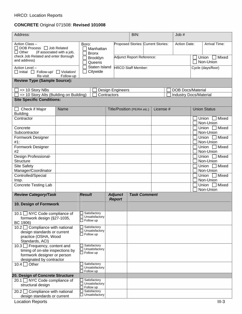
HRCO: Location Reports
Location Reports III-3
CONCRETE Original 071508: Revised 101008
Address: BIN: Job #
Proposed Stories: Current Stories: Action Date:
Arrival Time: Action Class – DOB Process Job Related Other (If associated with a job,
check Job Related and enter Borough and address)
Adjunct Report Reference: Union Mixed Non-Union
Action Level – Initial Follow-up/ Violation/
Re-visit Follow-up
Boro: Manhattan Bronx Brooklyn Queens Staten Island Citywide
HRCO Staff Member: Cycle (days/floor)
Review Type (Sample Source):
=> 10 Story NBs Design Engineers DOB Docs/Material => 10 Story Alts (Building on Building) Contractors Industry Docs/Material
Site Specific Conditions:
Check if Major Building
Name Title/Position (PE/RA etc.) License # Union Status
Contractor Union Mixed Non-Union
Concrete Subcontractor
Union Mixed Non-Union
Formwork Designer #1:
Union Mixed Non-Union
Formwork Designer #2
Union Mixed Non-Union
Design Professional-Structure
Union Mixed Non-Union
Site Safety Manager/Coordinator
Union Mixed Non-Union
Controlled/Special Insp.
Union Mixed Non-Union
Concrete Testing Lab Union Mixed Non-Union
Review Category/Task Result Adjunct Report
Task Comment
10. Design of Formwork
10.1 NYC Code compliance of formwork design (§27-1035,
BC 1906)
Satisfactory Unsatisfactory Follow up
10.2 Compliance with national design standards or current practice (OSHA, Wood Standards, ACI)
Satisfactory Unsatisfactory Follow up
10.3 Frequency, content and timing of on-site inspections by formwork designer or person designated by contractor
Satisfactory Unsatisfactory Follow up
10.4 Other Satisfactory Unsatisfactory Follow up
20. Design of Concrete Structure 20.1 NYC Code compliance of
structural design Satisfactory Unsatisfactory Follow up
20.2 Compliance with national design standards or current
Satisfactory Unsatisfactory

HRCO: Location Reports
Location Reports III-4
practice Follow up 20.3 Identification of required
inspections on plans Satisfactory Unsatisfactory Follow up
20.4 Frequency, content and timing of on-site inspections by registered design professional of record
Satisfactory Unsatisfactory Follow up
20.5 Other Satisfactory Unsatisfactory Follow up
30. On-Site Controls 30.1 Availability of approved site
safety plan Satisfactory Unsatisfactory Follow up
30.2 Availability of site safety log Satisfactory Unsatisfactory Follow up
30.3 Review of site safety log Satisfactory Unsatisfactory Follow up
30.4 Site Safety Personnel Present On-site
Satisfactory Unsatisfactory Follow up
30.5 Technical competence of site safety personnel
Satisfactory Unsatisfactory Follow up
30.6 Clarity of site safety warnings and notifications
Satisfactory Unsatisfactory Follow up
30.7 Public complaint analysis and interviews with public on concerns
Satisfactory Unsatisfactory Follow up
30.8 Required BEST Squad Notification (3-Digit #)
Satisfactory Unsatisfactory Follow up
30.9 Required Earthwork/ Excavation Notification per 1 RCNY §52-01 (5-Digit #)
Satisfactory Unsatisfactory Follow up
30.10 Sidewalk shed compliance with site safety plan
Satisfactory Unsatisfactory Follow up
30.11 Vertical netting compliance with site safety plan
Satisfactory Unsatisfactory Follow up
30.12 Horizontal netting compliance with site safety plan
Satisfactory Unsatisfactory Follow up
30.13 Tie-off compliance with site safety plan
Satisfactory Unsatisfactory Follow up
30.14 Adjacent building protection compliance with site safety plan
Satisfactory Unsatisfactory Follow up
30.15 Housekeeping Satisfactory Unsatisfactory Follow up
30.16 Barrier/site fence compliance
Satisfactory Unsatisfactory Follow up
30.17 On-site coordination between trades/contractors/site safety personnel
Satisfactory Unsatisfactory Follow up
30.18 Other Satisfactory Unsatisfactory Follow up
40. Form Assembly 40.1 Availability of formwork
design drawings on-site Satisfactory Unsatisfactory

HRCO: Location Reports
Location Reports III-5
Follow up 40.2 Signed and sealed design
drawings Satisfactory Unsatisfactory Follow up
40.3 Post spacing conformance with formwork design
Satisfactory Unsatisfactory Follow up
40.4 Stringer installation conformance with formwork design
Satisfactory Unsatisfactory Follow up
40.5 Rib installation/spacing conformance with formwork design
Satisfactory Unsatisfactory Follow up
40.6a Bracing conformance with formwork design
Satisfactory Unsatisfactory Follow up
40.6b Vertical formwork installation conformance
Satisfactory Unsatisfactory Follow up
40.7 Vertical formwork bracing conformance
Satisfactory Unsatisfactory Follow up
40.8 Workmanlike installation Satisfactory Unsatisfactory Follow up
40.9 On-site communication between supervisors and workers
Satisfactory Unsatisfactory Follow up
40.10 Physical protections for workers (PPE, safe practices)
Satisfactory Unsatisfactory Follow up
40.11 Observable indicators of insufficient training of workers assembling forms
Satisfactory Unsatisfactory Follow up
40.12 Frequency, content and timing Formwork inspection per 27-1035(b)(1)/BC1906.2
Satisfactory Unsatisfactory Follow up
40.13 Qualifications of person performing formwork inspection
Satisfactory Unsatisfactory Follow up
40.14. Other Satisfactory Unsatisfactory Follow up
50. Reinforcement Operations 50.1 Workmanlike operations in
placing reinforcing Satisfactory Unsatisfactory Follow up
50.2 Appropriate material storage
Satisfactory Unsatisfactory Follow up
50.3 Appropriate material handling
Satisfactory Unsatisfactory Follow up
50.4 Physical protections for workers (PPE, safe practices)
Satisfactory Unsatisfactory Follow up
50.5 Controlled/Special Inspector present on-site
Satisfactory Unsatisfactory Follow up
50.6 Qualifications of Controlled/ Special inspection personnel
Satisfactory Unsatisfactory Follow up
50.7 Frequency, content, and timing of Controlled/Special inspection
Satisfactory Unsatisfactory Follow up
50.8 Technical competence of Controlled/Special inspection personnel
Satisfactory Unsatisfactory Follow up

HRCO: Location Reports
Location Reports III-6
50.9 Availability of approved documents/shop drawings
Satisfactory Unsatisfactory Follow up
50.10 Review of field reports Satisfactory Unsatisfactory Follow up
50.11 Other Satisfactory Unsatisfactory Follow up
60. Concrete Placement Operations 60.1 Workmanlike concrete
placement operations Satisfactory Unsatisfactory Follow up
60.2 Appropriate material storage
Satisfactory Unsatisfactory Follow up
60.3 Appropriate material handling
Satisfactory Unsatisfactory Follow up
60.4 Material hoisting security and transfer methods
Satisfactory Unsatisfactory Follow up
60.5 Physical protections for workers (PPE, safe practices)
Satisfactory Unsatisfactory Follow up
60.7 Qualifications of concrete testing field personnel
Satisfactory Unsatisfactory Follow up
60.8 Frequency, content, and timing of concrete sampling
Satisfactory Unsatisfactory Follow up
60.9 Technical competence of concrete testing field personnel
Satisfactory Unsatisfactory Follow up
60.10 Controlled/Special Inspector present on-site (if different from Concrete Testing Lab)
Satisfactory Unsatisfactory Follow up
60.11 Qualifications of Controlled/Special inspection personnel
Satisfactory Unsatisfactory Follow up
60.12 Frequency, content, and timing of Controlled/Special inspection
Satisfactory Unsatisfactory Follow up
60.13 Technical competence of Controlled/Special inspection personnel
Satisfactory Unsatisfactory Follow up
60.14 Availability of approved documents/approved mixes
Satisfactory Unsatisfactory Follow up
60.15 Review of field reports Satisfactory Unsatisfactory Follow up
60.16 Other Satisfactory Unsatisfactory Follow up
70. Form Stripping 70.1 Form stripping sequence
available Satisfactory Unsatisfactory Follow up
70.2 Timing of cracking formwork in conformance with formwork design
Satisfactory Unsatisfactory Follow up
70.3 Sequencing of removal in conformance with formwork design
Satisfactory Unsatisfactory Follow up
70.4 Appropriate material handling
Satisfactory Unsatisfactory Follow up

HRCO: Location Reports
Location Reports III-7
70.5 Appropriate material storage
Satisfactory Unsatisfactory Follow up
70.6 On-site communication between supervisors and workers
Satisfactory Unsatisfactory Follow up
70.7 Physical protections for workers (PPE, safe practices)
Satisfactory Unsatisfactory Follow up
70.8 Technical competency of personnel stripping formwork
Satisfactory Unsatisfactory Follow up
70.9 Sufficient knowledge of concrete compressive strength available
Satisfactory Unsatisfactory Follow up
70.10 Other Satisfactory Unsatisfactory Follow up
80. Reshoring Operations 80.1 Reshoring sequence
available Satisfactory Unsatisfactory Follow up
80.2 Reshoring Post Spacing Design Available
Satisfactory Unsatisfactory Follow up
80.3 Number of Reshored Floors in Conformance with Reshoring Sequence
Satisfactory Unsatisfactory Follow up
80.4 Reshoring post spacing conformance
Satisfactory Unsatisfactory Follow up
80.5 Post tie-offs within 10ft of building edge
Satisfactory Unsatisfactory Follow up
80.6 Only screw-jacks within 10 ft of building edge
Satisfactory Unsatisfactory Follow up
80.7 Workmanlike installation Satisfactory Unsatisfactory Follow up
80.8 Other Satisfactory Unsatisfactory Follow up
90. Site Safety Plans (BEST) Review 90.1 Procedures review and
approval of applications Satisfactory Unsatisfactory Follow up
90.2 Content of documentation provided
Satisfactory Unsatisfactory Follow up
90.3 Technical capabilities for effective examination (Chiefs and DBCs)
Satisfactory Unsatisfactory Follow up
90.4 Training program content and effectiveness
Satisfactory Unsatisfactory Follow up
90.5 Other Satisfactory Unsatisfactory Follow up
100. Structural Plans (Boro) Review 100.1 Procedures review and
approval of applications Satisfactory Unsatisfactory Follow up
100.2 Content of documentation provided
Satisfactory Unsatisfactory Follow up
100.3 Technical capabilities for effective examination (Chiefs and DBCs)
Satisfactory Unsatisfactory Follow up

HRCO: Location Reports
Location Reports III-8
100.4 Training program content and effectiveness
Satisfactory Unsatisfactory Follow up
100.5 Other Satisfactory Unsatisfactory Follow up
110. DOB Inspections 110.1a Tasks performed for
each type of inspection Satisfactory Unsatisfactory Follow up
110.1b Level of detail at which a task should be performed
Satisfactory Unsatisfactory Follow up
110.2 Frequency of inspections after violations written
Satisfactory Unsatisfactory Follow up
110.3 Timing of inspections with respect to job phase
Satisfactory Unsatisfactory Follow up
110.4 Response time for complaint follow up
Satisfactory Unsatisfactory Follow up
110.5 Spot checks and audits of self-certified inspections/tests
Satisfactory Unsatisfactory Follow up
110.6 Technical capabilities for effective inspections
Satisfactory Unsatisfactory Follow up
110.7 Training programs content and effectiveness
Satisfactory Unsatisfactory Follow up
110.8 Content and usability and development of SOPs
Satisfactory Unsatisfactory Follow up
110.9 Content and usability and development of inspection checklists
Satisfactory Unsatisfactory Follow up
110.10 Other Satisfactory Unsatisfactory Follow up
Report Comments:

HRCO: Location Reports
Location Reports III-9
Task Time: Task Time Comments:
Travel Time: Travel Comments:
Office Time: Office Time Comments:
Violation(s) Issued: Requires Follow-up: Yes No DOB Inspector:
Report Prepared by: Report Approved
Print Name Yes Approver Name
Signature: Date approved: Signature
Additional HRCO Staff:
Print Name Signature:
Task Time: Task Time Comments:
Travel Time: Travel Comments:
Office Time: Office Time Comments:
Additional HRCO Staff:
Print Name Signature:
Task Time: Task Time Comments:
Travel Time: Travel Comments:
Office Time: Office Time Comments:

HRCO: Location Reports
Location Reports III-10
Crane Location Report

HRCO: Location Reports
Location Reports III-11
CRANES Original 071508 Revised 101008
Address: CD #: CN# Prot.# Proposed Stories: Current Stories: Action Date:
Arrival Time: Action Class –
DOB Process Job Related Other (If associated with a job,
check Job Related and enter Borough and address)
Adjunct Report Reference: Union Mixed Non-Union
Action Level – Initial Follow-up/ Violation/
Re-visit Follow-up
Boro: Manhattan Bronx Brooklyn Queens Staten Island Citywide
HRCO Staff Member: Cycle (days/floor):
Review Type (Sample Source): Tower Crane Other: Licensed Riggers Mobile Crane Design Engineer Equipment User (or Subs) Derrick Basic Configuration Types DOB Docs/Material Work Platform/Mast Climber Crane Owner Industry Docs/Material Hoist HMOs (In Use)
Site Specific Device Type: Tower Crane Mobile Crane Derrick Work Platform/Mast Climber Hoist Other: Manufacturer: Model:
Activity Under Review/Job Status:
Review Category/Task Result Adjunct Report
Task Comment
10. Design 10.1 Technical soundness of
design methods by model and configuration
Satisfactory Unsatisfactory Follow-up
10.2 Compliance with national and international design safety standards
Satisfactory Unsatisfactory Follow-up
10.3 Frequency, content, and timing of on site inspections
Satisfactory Unsatisfactory Follow-up
10.4 Practical application of design
Satisfactory Unsatisfactory Follow-up
10.5 Effect of having limited number of available crane engineers
Satisfactory Unsatisfactory Follow-up
10.6 Other Satisfactory Unsatisfactory Follow-up
20. Off-Site Controls 20.1 Labeling of critical
components and effectiveness thereof
Satisfactory Unsatisfactory Follow-up
20.2 Compliance with national design safety standards
Satisfactory Unsatisfactory Follow-up
20.3 Third-party review of service history, maintenance, and repair records
Satisfactory Unsatisfactory Follow-up
20.4 Third-party inspections and testing of structural/mechanical systems
Satisfactory Unsatisfactory Follow-up
20.5 Need for notification of mobile crane leaving yard/previous site
Satisfactory Unsatisfactory Follow-up
20.6 Other Satisfactory Unsatisfactory Follow-up

HRCO: Location Reports
Location Reports III-12
30. On-Site Controls 30.1 Communication between
owner/ user/operator of critical records
Satisfactory Unsatisfactory Follow-up
30.2 Clarity of public site safety warnings and notifications
Satisfactory Unsatisfactory Follow-up
30.3 Public complaint analysis and interviews with public on concerns
Satisfactory Unsatisfactory Follow-up
30.4 Pre-work planning for high risk operations
Satisfactory Unsatisfactory Follow-up
30.5 Physical protections from falling objects for public / adjacent buildings
Satisfactory Unsatisfactory Follow-up
30.6 On-site communications between contractors, HMOs, Riggers
Satisfactory Unsatisfactory Follow-up
30.7 Training program curricula, testing, and certification
Satisfactory Unsatisfactory Follow-up
30.8 Effectiveness of designated crane safety manager
Satisfactory Unsatisfactory Follow-up
30.9 Operational records and safety reporting (equipment, people)
Satisfactory Unsatisfactory Follow-up
30.10 Other Satisfactory Unsatisfactory Follow-up
40. Assembly 40.1 Delivery and component
handling and storage Satisfactory Unsatisfactory Follow-up
40.2 Assembly component inspection
Satisfactory Unsatisfactory Follow-up
40.3 Inspection of items difficult to view after assembly (i.e, pin connection)
Satisfactory Unsatisfactory Follow-up
40.4 Review of maintenance records
Satisfactory Unsatisfactory Follow-up
40.5 Maintenance frequency and methods
Satisfactory Unsatisfactory Follow-up
40.6 Other Satisfactory Unsatisfactory Follow-up
50. Disassembly 50.1 Component handling,
transfer, and storage Satisfactory Unsatisfactory Follow-up
50.2 Disassembly component inspection
Satisfactory Unsatisfactory Follow-up
50.3 Inspection of items difficult to view during operation (i.e, pin connection)
Satisfactory Unsatisfactory Follow-up
50.4 Review of maintenance records
Satisfactory Unsatisfactory Follow-up
50.5 Maintenance frequency and methods
Satisfactory Unsatisfactory Follow-up
50.6 Other Satisfactory Unsatisfactory

HRCO: Location Reports
Location Reports III-13
Follow-up 60. Self-Certified Testing 60.1 Allowable self-certifications Satisfactory
Unsatisfactory Follow-up
60.2 Technical soundness of testing
Satisfactory Unsatisfactory Follow-up
60.3 Application of other relevant testing methods
Satisfactory Unsatisfactory Follow-up
60.4 Frequency of inspections/tests
Satisfactory Unsatisfactory Follow-up
60.5 Relevancy of inspections/tests
Satisfactory Unsatisfactory Follow-up
60.6 Timing of inspections/tests Satisfactory Unsatisfactory Follow-up
60.7 Documentation of test results
Satisfactory Unsatisfactory Follow-up
60.8 Sufficiency of documentation
Satisfactory Unsatisfactory Follow-up
60.9 Other Satisfactory Unsatisfactory Follow-up
70. Operations 70.1 Material hoisting security
and transfer methods Satisfactory Unsatisfactory Follow-up
70.2 Requirement/effectiveness of licensed professional on site
Satisfactory Unsatisfactory Follow-up
70.3a On-site communications between supervisors and workers
Satisfactory Unsatisfactory Follow-up
70.3b Observable indicators of insufficient training
Satisfactory Unsatisfactory Follow-up
70.4 Observable indicators of poor housekeeping affecting crane ops
Satisfactory Unsatisfactory Follow-up
70.5 On-site proof of adequate training such as certifications
Satisfactory Unsatisfactory Follow-up
70.6 Physical protections for workers
Satisfactory Unsatisfactory Follow-up
70.7 Maintenance frequency and methods
Satisfactory Unsatisfactory Follow-up
70.8 Rigging means and methods during jumping operations
Satisfactory Unsatisfactory Follow-up
70.9 Other Satisfactory Unsatisfactory Follow-up
80. DOB Licensing 80.1 Licensing types and
limitations Satisfactory Unsatisfactory Follow-up
80.2 Testing content, relevance, and psychometrics for each license type
Satisfactory Unsatisfactory Follow-up
80.3 Testing administration process
Satisfactory Unsatisfactory Follow-up

HRCO: Location Reports
Location Reports III-14
80.4 Other Satisfactory Unsatisfactory Follow-up
90. DOB Review 90.1 Review and approval of
prototypes Satisfactory Unsatisfactory Follow-up
90.2 Review and approval of applications
Satisfactory Unsatisfactory Follow-up
90.3 Documentation provided up front and during the job’s life cycle
Satisfactory Unsatisfactory Follow-up
90.4 Notification to Buildings regarding job site phase changes
Satisfactory Unsatisfactory Follow-up
90.5 Technical capabilities for effective examination
Satisfactory Unsatisfactory Follow-up
90.6 Technical soundness of objections
Satisfactory Unsatisfactory Follow-up
90.7 Application of and compliance with national and international safety standards
Satisfactory Unsatisfactory Follow-up
90.8 Training program content and effectiveness
Satisfactory Unsatisfactory Follow-up
90.9 Other Satisfactory Unsatisfactory Follow-up
100. DOB Inspections 100.1 Tasks performed for each
type of inspection Satisfactory Unsatisfactory Follow-up
100.2 Level of detail at which a task should be performed
Satisfactory Unsatisfactory Follow-up
100.3 Frequency of inspections after violations written
Satisfactory Unsatisfactory Follow-up
100.4 Timing of inspections with respect to job phase
Satisfactory Unsatisfactory Follow-up
100.5 Response time for complaint follow up
Satisfactory Unsatisfactory Follow-up
100.6 Spot checks and audits of self-certified inspections/tests
Satisfactory Unsatisfactory Follow-up
100.7 Technical capabilities for effective inspections
Satisfactory Unsatisfactory Follow-up
100.8 Training programs (rigging, type, reporting) content and effectiveness
Satisfactory Unsatisfactory Follow-up
100.9 Content and usability and development of SOPs
Satisfactory Unsatisfactory Follow-up
100.10 Content and usability and development of inspection checklists
Satisfactory Unsatisfactory Follow-up
100.11 Effectiveness and appropriateness of inspection forms
Satisfactory Unsatisfactory Follow-up
100.12 Need for double-checks by supervisor for quality assurance
Satisfactory Unsatisfactory Follow-up

HRCO: Location Reports
Location Reports III-15
100.13 Appropriateness of inspector behavior/relations with workers
Satisfactory Unsatisfactory Follow-up
100.14 Other Satisfactory Unsatisfactory Follow-up
Report Comments:
Task Time: Task Time Comments:

HRCO: Location Reports
Location Reports III-16
Travel Time: Travel Comments:
Office Time: Office Time Comments:
Violation(s) Issued: Requires Follow-up: Yes No DOB Inspector:
Report Prepared by: Report Approved
Print Name Yes Approver Name
Signature: Date approved: Signature
Additional HRCO Staff:
Print Name Signature:
Task Time: Task Time Comments:
Travel Time: Travel Comments:
Office Time: Office Time Comments:
Additional HRCO Staff:
Print Name Signature:
Task Time: Task Time Comments:
Travel Time: Travel Comments:
Office Time: Office Time Comments:

HRCO: Location Reports
Location Reports III-17
Hoist Location Report

HRCO: Location Reports
Location Reports III-18
HOISTS Original 071508 Revised 101008
Address: CD #: CN# Prot.#
Proposed Stories: Current Stories: Action Date:
Arrival Time: Action Class – DOB Process Job Related Other (If associated with a job,
check Job Related and enter Borough and address)
Adjunct Report Reference: Union Mixed Non-Union
Action Level – Initial Follow-up/ Violation/
Re-visit Follow-up
Boro: Manhattan Bronx Brooklyn Queens Staten Island Citywide
HRCO Staff Member: Cycle (days/floor):
Review Type (Sample Source): Design Engineer Basic Configuration Types Owner DOB Docs/Material Operator Equipment User (or Subs) Licensed Riggers Industry Docs/Material
Activity Under Review/Job Status:
Site Specific Device Type: Hoist Other: Manufacturer: Model:
Review Category/Task Result Adjunct Report
Task Comment
10. DOB Process 10.1 Application Approval Satisfactory
Unsatisfactory Follow-up
10.2 Permit Process Satisfactory Unsatisfactory Follow-up
10.3 Acceptance Test (90 day temp issued)
Satisfactory Unsatisfactory Follow-up
10.4 Scheduled Test Appointment Notification
Satisfactory Unsatisfactory Follow-up
10.5 Other Satisfactory Unsatisfactory Follow-up
20. Design 20.1 P/M Hoist P/E Design with
Technical Drawing Satisfactory Unsatisfactory Follow-up
20.2 Material Hoist P/E Design with Technical Drawing
Satisfactory Unsatisfactory Follow-up
20.3 Backstructure P/E Design with Technical Drawing (including tie removal/ replacement program)
Satisfactory Unsatisfactory Follow-up
20.4 P/E Sign off of Hoist/ Backstructure Loading Imposed on Building
Satisfactory Unsatisfactory Follow-up
20.5 Other Satisfactory Unsatisfactory Follow-up
30. Off-Site Controls 30.1 Maintenance Log of Hoist Car
Satisfactory Unsatisfactory Follow-up
30.2 Hoist Mast Maintenance/ Quality Control Compliance
Satisfactory Unsatisfactory Follow-up
30.3 Safety Expiration Date in Compliance
Satisfactory Unsatisfactory Follow-up
30.4 Other Satisfactory Unsatisfactory Follow-up
40. On-Site Controls (P/M Hoists)

HRCO: Location Reports
Location Reports III-19
40.1 Original Inspection Certificate
Satisfactory Unsatisfactory Follow-up
40.2 Personnel Hoist Operating Instruction
Satisfactory Unsatisfactory Follow-up
40.3 Names of Qualified Operators & Operator Qualifications
Satisfactory Unsatisfactory Follow-up
40.4 Material Handling Plans Approved by Site Safety Manager
Satisfactory Unsatisfactory Follow-up
40.5 Required Signage and Tag Satisfactory Unsatisfactory Follow-up
40.6 Hoist Base Secure to Pad Satisfactory Unsatisfactory Follow-up
40.7 Pit Housekeeping Satisfactory Unsatisfactory Follow-up
40.8 Lower Limit Compliance Satisfactory Unsatisfactory Follow-up
40.9 Base Enclosure Satisfactory Unsatisfactory Follow-up
40.10 Pit Access Compliance Satisfactory Unsatisfactory Follow-up
40.11 Loading Dock Design Compliance
Satisfactory Unsatisfactory Follow-up
40.12 Loading Dock Overhead Protection Design Compliance
Satisfactory Unsatisfactory Follow-up
40.13 Loading Dock Access/Guardrail Compliance
Satisfactory Unsatisfactory Follow-up
40.14 Landing Gate Size Compliance
Satisfactory Unsatisfactory Follow-up
40.15 Landing Gate/ Car Clearance
Satisfactory Unsatisfactory Follow-up
40.16 Landing Gate Latch Accessibility from Landing
Satisfactory Unsatisfactory Follow-up
40.17 Landing Min 30" Protection Shield Either Side of Gate
Satisfactory Unsatisfactory Follow-up
40.18 Hoistway Protection where Assessable
Satisfactory Unsatisfactory Follow-up
40.19 Power Cable Traveler and Guides in Compliance
Satisfactory Unsatisfactory Follow-up
40.20 Static Power Cable Secured to tower in Compliance
Satisfactory Unsatisfactory Follow-up
40.21 Traveling Cable Connection to Tower in Compliance
Satisfactory Unsatisfactory Follow-up
40.22 Hoist Car to Landing Clearance in Compliance
Satisfactory Unsatisfactory Follow-up
40.23 Landing Gate Mounting In Compliance
Satisfactory Unsatisfactory Follow-up
40.24 Floors Properly Marked Satisfactory Unsatisfactory Follow-up
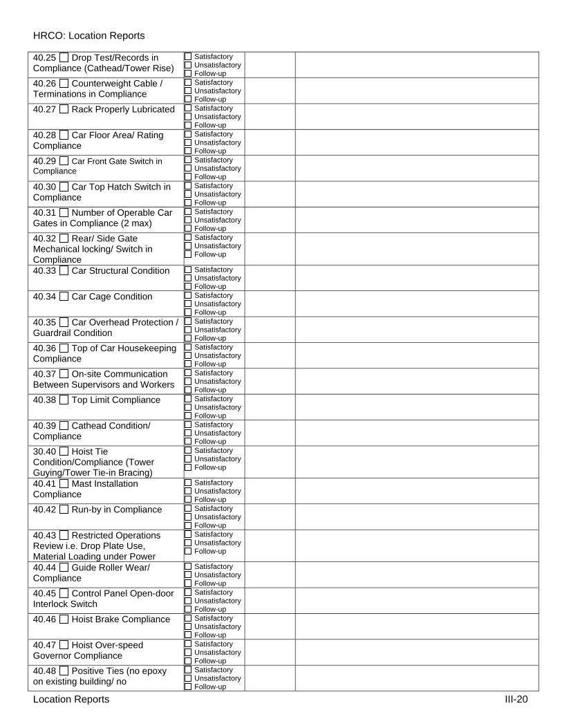
HRCO: Location Reports
Location Reports III-20
40.25 Drop Test/Records in Compliance (Cathead/Tower Rise)
Satisfactory Unsatisfactory Follow-up
40.26 Counterweight Cable / Terminations in Compliance
Satisfactory Unsatisfactory Follow-up
40.27 Rack Properly Lubricated Satisfactory Unsatisfactory Follow-up
40.28 Car Floor Area/ Rating Compliance
Satisfactory Unsatisfactory Follow-up
40.29 Car Front Gate Switch in Compliance
Satisfactory Unsatisfactory Follow-up
40.30 Car Top Hatch Switch in Compliance
Satisfactory Unsatisfactory Follow-up
40.31 Number of Operable Car Gates in Compliance (2 max)
Satisfactory Unsatisfactory Follow-up
40.32 Rear/ Side Gate Mechanical locking/ Switch in Compliance
Satisfactory Unsatisfactory Follow-up
40.33 Car Structural Condition Satisfactory Unsatisfactory Follow-up
40.34 Car Cage Condition Satisfactory Unsatisfactory Follow-up
40.35 Car Overhead Protection / Guardrail Condition
Satisfactory Unsatisfactory Follow-up
40.36 Top of Car Housekeeping Compliance
Satisfactory Unsatisfactory Follow-up
40.37 On-site Communication Between Supervisors and Workers
Satisfactory Unsatisfactory Follow-up
40.38 Top Limit Compliance Satisfactory Unsatisfactory Follow-up
40.39 Cathead Condition/ Compliance
Satisfactory Unsatisfactory Follow-up
30.40 Hoist Tie Condition/Compliance (Tower Guying/Tower Tie-in Bracing)
Satisfactory Unsatisfactory Follow-up
40.41 Mast Installation Compliance
Satisfactory Unsatisfactory Follow-up
40.42 Run-by in Compliance Satisfactory Unsatisfactory Follow-up
40.43 Restricted Operations Review i.e. Drop Plate Use, Material Loading under Power
Satisfactory Unsatisfactory Follow-up
40.44 Guide Roller Wear/ Compliance
Satisfactory Unsatisfactory Follow-up
40.45 Control Panel Open-door Interlock Switch
Satisfactory Unsatisfactory Follow-up
40.46 Hoist Brake Compliance Satisfactory Unsatisfactory Follow-up
40.47 Hoist Over-speed Governor Compliance
Satisfactory Unsatisfactory Follow-up
40.48 Positive Ties (no epoxy on existing building/ no
Satisfactory Unsatisfactory Follow-up

HRCO: Location Reports
Location Reports III-21
compression ties) 40.49 Car Operating Station in compliance
Satisfactory Unsatisfactory Follow-up
40.50 Buffers Satisfactory Unsatisfactory Follow-up
40.51 Protection of Spaces Under Hoist
Satisfactory Unsatisfactory Follow-up
40.52 Power Shutoff in Sight of Main Unit at Loading Dock (Not Pit)
Satisfactory Unsatisfactory Follow-up
40.53 All Steel Plates Used for Bridging Tethered and Secure in Car When not in Use
Satisfactory Unsatisfactory Follow-up
40.54 Personnel Hoist and Material Hoist Cannot Share the Same Hoisting
Satisfactory Unsatisfactory Follow-up
40.55 Disassembly and Removal
Satisfactory Unsatisfactory Follow-up
40.56 Other Satisfactory Unsatisfactory Follow-up
50. Backstructure 50.1 Protection of Spaces under Hoistway in Compliance
Satisfactory Unsatisfactory Follow-up
50.2 Retiring in Compliance Satisfactory Unsatisfactory Follow-up
50.3 Backstructure Structural Compliance
Satisfactory Unsatisfactory Follow-up
50.4 Guardrail, Toeboard and Mesh Compliance
Satisfactory Unsatisfactory Follow-up
50.5 Backstructure Tie Compliance
Satisfactory Unsatisfactory Follow-up
50.6 Tie Removal/Replacement Program in Compliance
Satisfactory Unsatisfactory Follow-up
50.7 Other Satisfactory Unsatisfactory Follow-up
60. Material Only Hoist 60.1 Material Handling Plans Approved by Site Safety Manager
Satisfactory Unsatisfactory Follow-up
60.2 Material Hoist Base Mount to Base Pad in Compliance
Satisfactory Unsatisfactory Follow-up
60.3 Hoist Tower Structure in Compliance
Satisfactory Unsatisfactory Follow-up
60.4 Hoist Tower Enclosure Satisfactory Unsatisfactory Follow-up
60.5 Base Enclosure in Compliance
Satisfactory Unsatisfactory Follow-up
60.6 Loading Dock in Compliance
Satisfactory Unsatisfactory Follow-up
60.7 Overhead Protection in Compliance
Satisfactory Unsatisfactory Follow-up
60.8 Drop Bar Gate/ Landing Gate Compliance
Satisfactory Unsatisfactory

HRCO: Location Reports
Location Reports III-22
Follow-up 60.9 Clearance of Car to Landing
Satisfactory Unsatisfactory Follow-up
60.10 Car Structure in Compliance
Satisfactory Unsatisfactory Follow-up
60.11 Car Cage in Compliance (Opened from Landing Side)
Satisfactory Unsatisfactory Follow-up
60.12 Car Safety Compliance Satisfactory Unsatisfactory Follow-up
60.13 Tower Run-by in Compliance
Satisfactory Unsatisfactory Follow-up
60.14 Tower Ties in Compliance (Tower Guying/Tower Tie-in Bracing)
Satisfactory Unsatisfactory Follow-up
60.15 Winch Compliance Satisfactory Unsatisfactory Follow-up
60.16 Operator Shanty Compliance with Overhead Protection
Satisfactory Unsatisfactory Follow-up
60.17 Operator Communication in Compliance
Satisfactory Unsatisfactory Follow-up
60.18 Winch to Tower Connection in Compliance
Satisfactory Unsatisfactory Follow-up
60.19 Deflector Sheaves/ Fleet Angle in Compliance
Satisfactory Unsatisfactory Follow-up
60.20 Operator House Support Structure in Compliance
Satisfactory Unsatisfactory Follow-up
60.21 Cathead Structure in Compliance
Satisfactory Unsatisfactory Follow-up
60.22 Cable Inspection Compliance include Terminations
Satisfactory Unsatisfactory Follow-up
60.23 Number of Minimum Cable Wraps on Drum in Compliance
Satisfactory Unsatisfactory Follow-up
60.24 Required Signs in Compliance (i.e. No Riders, Rating)
Satisfactory Unsatisfactory Follow-up
60.25 All Steel Plates Used for Bridging Tethered and Secure in Car When not in Use
Satisfactory Unsatisfactory Follow-up
60.26 Personnel Hoist and Material Hoist Cannot Share the Same Hoisting
Satisfactory Unsatisfactory Follow-up
60.27 Positive Ties (no epoxy on existing building/ no compression ties)
Satisfactory Unsatisfactory Follow-up
60.28 Main Line in Operator's Shanty
Satisfactory Unsatisfactory Follow-up
60.29 Other Satisfactory Unsatisfactory Follow-up
70. DOB Inspections 70.1 Tasks performed for each
type of inspection Satisfactory Unsatisfactory Follow-up
70.2 Level of detail at which a Satisfactory

HRCO: Location Reports
Location Reports III-23
task should be performed Unsatisfactory Follow-up
70.3 Frequency of inspections after violations written
Satisfactory Unsatisfactory Follow-up
70.4 Timing of inspections with respect to job phase
Satisfactory Unsatisfactory Follow-up
70.5 Response time for complaint follow up
Satisfactory Unsatisfactory Follow-up
70.6 Spot checks and audits of self-certified inspections/tests
Satisfactory Unsatisfactory Follow-up
70.7 Technical capabilities for effective inspections
Satisfactory Unsatisfactory Follow-up
70.8 Training programs (rigging, type, reporting) content and effectiveness
Satisfactory Unsatisfactory Follow-up
70.9 Content and usability and development of SOPs
Satisfactory Unsatisfactory Follow-up
70.10 Content and usability and development of inspection checklists
Satisfactory Unsatisfactory Follow-up
70.11 Effectiveness and appropriateness of inspection forms
Satisfactory Unsatisfactory Follow-up
70.12 Need for double-checks by supervisor for quality assurance
Satisfactory Unsatisfactory Follow-up
70.13 Appropriateness of inspector behavior/relations with workers
Satisfactory Unsatisfactory Follow-up
70.14 Other Satisfactory Unsatisfactory Follow-up
Report Comments:

HRCO: Location Reports
Location Reports III-24
Task Time: Task Time Comments:
Travel Time: Travel Comments:
Office Time: Office Time Comments:
Violation(s) Issued: Requires Follow-up: Yes No DOB Inspector:
Report Prepared by: Report Approved
Print Name Yes Approver Name
Signature: Date approved: Signature
Additional HRCO Staff:
Print Name Signature:
Task Time: Task Time Comments:
Travel Time: Travel Comments:
Office Time: Office Time Comments:
Additional HRCO Staff: Print Name Signature:
Task Time: Task Time Comments: Travel Time: Travel Comments:
Office Time: Office Time Comments:

HRCO: Location Reports
Location Reports III-25
Excavation Location Report

General Site Information/BIS ListingAddress: BIN: Job No.: Page 1 of 4
DOB Process Initial Site Visit HRCO Engineer(s): Inspection Date:
Job Related (enter Borough and address) Follow-up Visit
Architect: Structural Engineer: Geotechnical Engineer: Borough: Job Status (Select One):
Manhattan Not Started
General Contractor: Subgrade Consultant: Excavation/SOE Contractor: Bronx Exc/SSB/UP
Brooklyn Foundation
Controlled Inspector: Yes If Not, Date of Last Visit Yes Queens Demolition
No No Staten Island Other:
NB Description and Site InformationProposed NB Stories: Current NB Stories: No. Basement Levels: Proposed NB Elevator: None
Foundation Class: Identify Foundation Type(s): Pile ( Pipe HP or W Flng ) Isolated Central
Shallow (<12') Spread Caisson or Drilled Shaft Isolated on Perimeter
Deep (>12') Mat Micropile Adjacent to Existing Bldg
Soil Conditions: SOIL to 50' below grade ROCK within 50' of grade Thin SOIL over ROCK
Soil Type: Hard Sound Rock Intermediate Rock Hardpan Coarse Sand Clay Engineered Fill
Med Hard Rock Soft Rock Gravel/Gravel Soils Fine Sand Silt Unsuitable
EX, SSB, UP Permits: Excavation Design and Status: SOE Status: Underpinning Design and Status: Soil Berms:
NB Less Than 12' Not Started (N/A) Not Started (N/A) None (N/A) Not Started None (or N/A)
ALT 2 with NB Greater Than 12' < 50% Excavated < 50% Installed Single Lift < 50% Installed 2' High
ALT 2 without NB > 50% Excavated > 50% Installed 2 Lifts > 50% Installed 5' High
None (N/A) Complete Complete > 2 Lifts Complete > 5' High
General ResultsInspection: Site Observations: Exceptions:
Job Not Started (N/A) Soil or pavement settlement behind SOE Permit/Design Drawings not on-site
No Access to Site (Closed) Structure settlement/distress associated with SOE Work not performed in accordance with Permit/Design Drwgs
Access Denied Structure settlement/distress associated with UP Minor (practical tolerance) Moderate
Site Inactive (No Contractor) Structure settlement/distress associated with water mgmt Significant Changed Condition
Comments
Comments
Comments
Yes If yes, list Complaint No. from EOC:
No Emergency Operation Center (212.566.3415) For Non-Emergency contact DOB Customer Service (212.566.5232)
Report Prepared By: Report Approved By:
Print Name: Print Name:
Signature (Date): Signature (Date):
HRS
LOCATION REPORT - EXCAVATION UNIT
Variation:
Action Level:
Total Task Time:
Action Class:
CI On-Site TR1 On-Site
Travel Time: HRS
Office/Reporting Time: HRS
Potential Violation Reported:
HRCO: Location Reports
Location Reports III-26

General Site Information/BIS ListingAddress: BIN: Inspection Date:
10 SOE and UP Design: As reviewed in the FIELDAdequate
MIN Inadequate
Incomplete (Revisit)
Adequate
MIN Inadequate
Incomplete (Revisit)
Adequate
MIN Inadequate
Incomplete (Revisit)
Adequate
MIN Inadequate
Incomplete (Revisit)
Adequate
MIN Inadequate
Incomplete (Revisit)
20 SOE and UP Design: As reviewed in the OFFICEAdequate
MIN Inadequate
Incomplete (Revisit)
Adequate
MIN Inadequate
Incomplete (Revisit)
Adequate
MIN Inadequate
Incomplete (Revisit)
Adequate
MIN Inadequate
Incomplete (Revisit)
Adequate
MIN Inadequate
Incomplete (Revisit)
Adequate
MIN Inadequate
Incomplete (Revisit)
30 On-Site ControlsAdequate
MIN Inadequate
Incomplete (Revisit)
Adequate
MIN Inadequate
Incomplete (Revisit)
Adequate
MIN Inadequate
Incomplete (Revisit)
Adequate
MIN Inadequate
Incomplete (Revisit)
Page 2 of 4
Technical COMPLETENESS of permitted subgrade SOE design dwgs (Are sufficient sections and dimensions shown, are details clear, etc.)
Time Spent EvaluationComments
Technical SOUNDNESS of permitted subgrade NB design (Do the Architectural and Structural dwgs correspond to the EX/SOE dwgs)
10.1
Review Category/Task
10.5 General Conformance with NYC BUILDING CODE design standards
10.2
Technical COMPLETENESS of permitted subgrade NB design dwgs (Are adjacent structures depicted, SOE/UP details shown, etc.)
10.3
Technical SOUNDNESS of permitted subgrade SOE design (Is the system suitable for the site conditions, is it adequately proportioned, etc.)
10.4
20.4
Technical COMPLETENESS of permitted subgrade SOE design dwgs (Are sufficient sections and dimensions shown, are details clear, etc.)
20.1
Technical SOUNDNESS of permitted subgrade NB design (Do the Architectural and Structural dwgs correspond to the EX/SOE dwgs)
20.2
Technical COMPLETENESS of permitted subgrade NB design dwgs (Are adjacent structures depicted, SOE/UP details shown, etc.)
30.1 Clarity of public site safety warnings and notifications
20.5 General Conformance to NYC BUILDING CODE design standards
20.6General Conformance to NATIONAL (IBC, AASHTO, FHWA, USACE, etc.) design standards
30.2 Apparent Pre-work planning operations and coordination efforts
30.3 Physical protections from falling objects for public and adjacent buildings
30.4 Notification to Department of Buildings regarding job operations (Rule 52)
20.3
Technical SOUNDNESS of permitted subgrade SOE design (Is the system suitable for the site conditions, is it adequately proportioned, etc.)
HRCO: Location Reports
Location Reports III-27

General Site Information/BIS ListingAddress: BIN: Inspection Date:
40 On-Site Observations: Excavation OperationsAdequate
MIN Inadequate
Incomplete (Revisit)
Adequate
MIN Inadequate
Incomplete (Revisit)
Adequate
MIN Inadequate
Incomplete (Revisit)
Adequate
MIN Inadequate
Incomplete (Revisit)
Adequate
MIN Inadequate
Incomplete (Revisit)
Adequate
MIN Inadequate
Incomplete (Revisit)
Adequate
MIN Inadequate
Incomplete (Revisit)
Adequate
MIN Inadequate
Incomplete (Revisit)
Adequate
MIN Inadequate
Incomplete (Revisit)
Adequate
MIN Inadequate
Incomplete (Revisit)
50 DOB ReviewAdequate
MIN Inadequate
Incomplete (Revisit)
Adequate
MIN Inadequate
Incomplete (Revisit)
Adequate
MIN Inadequate
Incomplete (Revisit)
Adequate
MIN Inadequate
Incomplete (Revisit)
Evaluation
Review Category/Task Time Spent Comments
Review Category/Task Time Spent
Evaluation
Monitoring of adjacent property 40.2
40.1 Adjacent property survey
40.4 Excavation means and methods
40.3Restriction of SOE and Excavation operations to avoid encroachment of adjacent properties
40.5 SOE System construction/installation
40.6 Underpinning construction/installation
40.7 Testing methods and reporting of results
40.8 On-site communications between supervisors and workers
40.9 Worker/Operator training and familiarity with activity
40.10 Physical protections for workers
50.1 Review and approval of applications
50.2 Content of documentation provided
50.3 Technical capabilities for effective examination (Chiefs and DBCs)
50.4 Training program content and effectiveness
Comments
Page 3 of 4
HRCO: Location Reports
Location Reports III-28

General Site Information/BIS ListingAddress: BIN: Inspection Date:
60 DOB InspectionsAdequate
MIN Inadequate
Incomplete (Revisit)
Adequate
MIN Inadequate
Incomplete (Revisit)
Adequate
MIN Inadequate
Incomplete (Revisit)
Adequate
MIN Inadequate
Incomplete (Revisit)
Adequate
MIN Inadequate
Incomplete (Revisit)
Adequate
MIN Inadequate
Incomplete (Revisit)
Adequate
MIN Inadequate
Incomplete (Revisit)
Adequate
MIN Inadequate
Incomplete (Revisit)
Adequate
MIN Inadequate
Incomplete (Revisit)
Adequate
MIN Inadequate
Incomplete (Revisit)
70 Site SafetyProtection for Workers: Protection of Public:
70.1 Harnesses Adequate Inadequate None N/A 70.6 Sidewalk sheds Adequate Inadequate None N/A
70.2 2(+) routes of egress Adequate Inadequate None N/A 70.7 Fences/netting Adequate Inadequate None N/A
70.3 Guardrails Adequate Inadequate None N/A 70.8 Jersey barrier Adequate Inadequate None N/A
70.4 Overhead protection Adequate Inadequate None N/A 70.9 Lighting Adequate Inadequate None N/A
70.5 Hardhats/PPE Adequate Inadequate None N/A
General Comments
60.3 Frequency of inspections after violations written
60.4 Timing of inspections with respect to job phase
60.10 Content and usability and development of inspection checklists
60.7 Technical capabilities for effective inspections
60.8 Training programs content and effectiveness
60.9 Content and usability and development of SOPs
60.5 Response time for complaint follow up
60.6 Spot checks and audits of self-certified inspections/tests
60.1 Tasks performed for each type of inspection
60.2 Level of detail at which a task should be performed
Page 4 of 4
Review Category/Task Time Spent Comments Evaluation
HRCO: Location Reports
Location Reports III-29

HRCO: Location Reports
Location Reports III-30
Permit Audit Report

General Site Information/BIS Listing HRCO Engineer(s): Audit Date:Address: BIN: Job No.:
Site Plan (Basic Elements)Items N/A Adequate Inadequate Yes No Adequate Inadequate
10.1 Adjacent Buildings (No. of Stories, Basements, etc. )
10.2 Utilities
10.3 Property Lines
10.4 Streets and Sidewalks
10.5 Excavation Limits and Slopes
10.6 NB Foundations and/or Column Lines
10.7 SOE Comp (Soldier Piles, Sheetpile, Timber Shoring, etc. )
10.8 Underpinning Alignment with Sequence
10.9 Anchorage (Tieback, Internal Bracing, Rakers) Comp
10.10 Section Callouts Identified
10.11 North Arrow
10.12
10.13
Site Plan (Dimensions)Items N/A Adequate Inadequate Yes No Adequate Inadequate
10.21 Elevation Reference
10.22 Setback and Encroachment of Foundation Elements
10.23 SOE Offset from Property Lines and Utilities
10.24 Center-to-Center Spacing of Soldier Piles
10.25 Underpinning Extent
10.26 Dewatering Components
10.27
10.28
10.29
10.30
SOE Cross-SectionsItems N/A Adequate Inadequate Yes No Adequate Inadequate
20.1 Subsurface Soil and Groundwater Conditions
20.2 Exst Foundations (Type, Dimensions, and Bearing Elev)
20.3 Utilities (Type, Dimensions, and Bearing Elevation)
20.4 Offset (to Fnds and Utilities) and Encroachment Dim
20.5 Exst Grade, Intermediate Stages, and Final Excav Elev
20.6 Berm Dimensions
20.7 Top and Tip Elevation of Sheeting and Soldier Piles
20.8 Anchor and Wale Elevation
20.9 Anchorage Dimensions (Tieback and Deadman)
20.10 Installation/Excavation Staging Sequence
20.11 At Least 1 Section at Each Side of Excavation
20.12 At Least 1 Typ Section Extends Beyond the Active Zone
20.14
20.15
Requested Change Final Drawing
Original Permit Requested Change Final Drawing
Original Permit
Comments
AUDIT CHECKLIST - EXCAVATION UNIT
Requested Change Final DrawingOriginal Permit
Page 1 of 2DSD
Comments
Comments
HRCO: Location Reports
Location Reports III-31

General Site Information/BIS Listing HRCO Engineer(s): Audit Date:Address: BIN: 0 Job No.: 0
Underpinning Cross-SectionsItems N/A Adequate Inadequate Yes No Adequate Inadequate
20.21 Subsurface Conditions (Soil/Rock Type and Allow Brg)
20.22 Existing Foundations (Type, Dimensions, and Brg Elev)
20.23 Bearing Elevation of Underpinning
20.24 Lift Sequence, Box Pit and Pin Dimensions
20.25 Approach Pit Dimensions, Excavation Slopes
20.26 Bracing and/or Shoring for Sideslopes
20.27 Anchorage/Bracing Elevations and Dimensions
20.28 Installation Sequence
20.29 Shimming/Dry Pack Requirements and Schedule
20.30 At Least 1 Section at Each Adjacent Building
20.31
Anchorage (Grouted Tiebacks or Alternate)Items N/A Adequate Inadequate Yes No Adequate Inadequate
30.1 Soil/Rock Type in Bond Zone
30.2 Bonded/Unbonded Length
30.3 Diameter of Bond Zone
30.4 Design Capacity/Lock-off Load
30.5 Component Sizes (Threadbar, Hollowbar, Tendon)
30.6 Installation Angle
30.7 Grout Strength
30.8 Proof/Production Test Requirements and Schedule
30.9 Raker/Bracing Dimensions
30.10
30.11
Connections, Misc Details, And SpecificationsItems N/A Adequate Inadequate Yes No Adequate Inadequate
40.1 Size/Extent of Welds
40.2 Electrode Type
40.3 Stiffener Plates (Spacing and Dimensions)
40.4 Wale Support and Knee Brace Dimensions
40.5 Bearing Plate Dimensions
40.6 Splice Detail
40.7 Material Specs (Steel Gr, Lagging, Conc Strength, etc. )
40.8
ReinforcementItems N/A Adequate Inadequate Yes No Adequate Inadequate
50.1 Bar and Dowel Sizes
50.2 Spacing
50.3 Lengths
50.4 Bend Requirements
50.5
50.6
50.7
Page 2 of 2
Requested Change Final Drawing
Original Permit Requested Change Final Drawing
Requested Change Final Drawing
Original Permit Requested Change Final Drawing
Original Permit
1/0/1900
Original Permit
Comments
Comments
Comments
Comments
0 DSD
HRCO: Location Reports
Location Reports III-32


