High Resistance Fault Locator - Radiodetection · PDF fileT272 Operating Manual Page 5 Murray...
14
T272 High Resistance Fault Locator Refer to Preface & Safety Instructions before operating Applicable from serial no. 37888 onwards Operation Manual l Issue 5 l September 2008 00901183-5
Transcript of High Resistance Fault Locator - Radiodetection · PDF fileT272 Operating Manual Page 5 Murray...

T272High Resistance Fault Locator Refer to Preface & Safety Instructions before operating
Applicable from serial no. 37888 onwards
Operation Manual l Issue 5 l September 2008
00901183-5
T272 Operating Manual
Contents
1. Health and Safety at Work.............................................................................................. 13. Technical Specification................................................................................................... 24. Connections..................................................................................................................... 2Connections both ends available - ...................................................................................... 3Operation............................................................................................................................. 6
Radiodetection Ltd. 00901183-5
Copyright 2008 Radiodetection Ltd - SPX Corporation. All rights reserved.Radiodetection is a subsidiary of SPX Corporation.SPX and Radiodetection are trademarks of Radiodetection Ltd. and SPX Corporation. Due to a policy of continued development, we reserve the right to alter or amend any published specification without notice.
Copyright 2008 Radiodetection Ltd - SPX Corporation.This document is protected by copyright and may not be copied, reproduced, transmitted, modified or used, in whole or in part, without the prior written consent of Radiodetection Ltd.

T272 Operating Manual
Page 1
1. Health and Safety at Work 1.1 Health And Safety At Work Act 1974 Section 6.1 (c) This product is tested and supplied in accordance with our published specifications and, when used in normal or prescribed applications within the parameters specified for mechanical and electrical performance, will not cause danger or hazard to health or safety, provided that normal engineering and safety practices are observed and such products are used only by trained and qualified persons.
All usage of this product must be in accordance with this Operating Manual and any work on the electrical components housed within the machine must be undertaken by qualified personnel.
If there is any doubt about any aspect relating to the correct use of this equipment contact Radiodetection Ltd. Western Drive, Bristol BS14 0AF. United Kingdom.
Please also study the Product Safety Data Section 9 before using the equipment.
2. Introduction This manual is a guide to the operation and maintenance of the High Resistance Fault Locator, Model T272. The instrument has been designed to meet the requirements of the cable testing and fault locating Engineer, to locate cable faults where the resistance ranges from zero to 200 MΩ. Faults can be between two conductors or between a conductor and its metallic sheath, concentric neutral, or earth.
Easy to operate, the T272 features solid state circuitry and utilises a conventional Wheatstone bridge circuit in which the two sections of the faulty conductor, one on each side of the fault, together with a good conductor if necessary, comprise the two external arms of the bridge. The other two arms of the bridge are contained within the instrument.
By employing a detection circuit of extremely high input resistance it is possible to locate high resistance faults without the loss of sensitivity associated with other types of low and high voltage bridges. A ten-turn Vernier balancing control is provided which indicates the fault position as a percentage of the total loop length. If both ends of the faulty conductor are not accessible at the test end then a good conductor of the same cross-sectional area is required. If the good conductor is of a different size then a conversion factor may be used to calculate an equivalent loop length, or a pair of healthy conductors may be used in which case the resistance is not critical.
Radiodetection Ltd. 00901183-5
T272 Operating Manual
Page 2
3. Technical Specification Power Supply for Instrument (Internal) 9 V battery, PP3 or equivalent Power Supply for Bridge Network (External) A DC source with output voltage to suit
the cable under test must be provided, e.g. 6 or 12V car battery for power cables, or a zinc chloride battery for smaller cable sizes and telephone cables.
Size 155 x 245 x 102 mm Weight 1.4 kg
The following leads are included to enable the fault locations detailed in section 4.1 and 4.2.1 to be carried out.
The Green lead is used to make the connection from the sheath terminal on the bridge. The two core Red lead is used to connect the faulty conductor to the ‘Red’ conductor terminal on the bridge and to one side of the “external” battery. The two core Black lead is used to connect the sound conductor to the ‘Black’ conductor terminal and the other side of the “external” battery. With this bridge arrangement, faults having resistances up to 200 MΩ in dielectrics such as rubber and polyethylene can be located with an accuracy well within +0.5% of the loop length and typically 0.1% although this may be limited by the non-uniformity of the conductor. The instrument is contained within a plastic housing fitted with a carrying strap. terminals, controls, and the null detector (micro ammeter) are mounted on the top panel.
4. Connections
WARNING Do not connect this instrument to a live or charged cable. Ensure that the cable to be tested has been completely discharged and earthed and that all normal safety procedures have been followed. To prevent “post -charging”, such as may take place after a DC voltage or insulation resistance test, ensure that the cable has been earthed for an adequate length of time before connecting the instrument.
4.1 Connections to a faulty cable on a drum or ring circuit In this scenario both ends of the faulty conductor are accessible at the test end. This is
the case during cable manufacture or when the cable is on a cable drum, or forms a “ring” circuit.
The following connection arrangements should be made (see figures 1 and 2). 4.1.1 Prepare the cable ends by stripping back the sheath at least 150 mm from each end.
Expose at least 100 mm of conductor and clean to remove oil and other impurities. In the case of smaller cable sizes and telephone cable these dimensions may be scaled down.
4.1.2 The leads provided (Red and Black) are terminated at one end with crocodile clips on
both conductors, and at the other end with a 4 mm “Banana” plug on one conductor and a crimp connector on the other.
Radiodetection Ltd. 00901183-5
T272 Operating Manual
Page 3
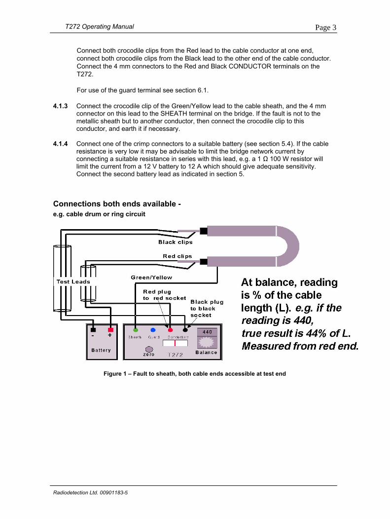
Connect both crocodile clips from the Red lead to the cable conductor at one end, connect both crocodile clips from the Black lead to the other end of the cable conductor. Connect the 4 mm connectors to the Red and Black CONDUCTOR terminals on the T272.
For use of the guard terminal see section 6.1.
4.1.3 Connect the crocodile clip of the Green/Yellow lead to the cable sheath, and the 4 mm connector on this lead to the SHEATH terminal on the bridge. If the fault is not to the metallic sheath but to another conductor, then connect the crocodile clip to this conductor, and earth it if necessary.
4.1.4 Connect one of the crimp connectors to a suitable battery (see section 5.4). If the cable
resistance is very low it may be advisable to limit the bridge network current by connecting a suitable resistance in series with this lead, e.g. a 1 Ω 100 W resistor will limit the current from a 12 V battery to 12 A which should give adequate sensitivity. Connect the second battery lead as indicated in section 5.
Connections both ends available - e.g. cable drum or ring circuit
Figure 1 – Fault to sheath, both cable ends accessible at test end
Radiodetection Ltd. 00901183-5

T272 Operating Manual
Page 4
4.2 Connections to a faulty installed cable In this scenario the ends of the faulty conductor are not accessible at the same point. This would be the case of a cable in service. One of the following methods may be used. 4.2.1 The more common method is to use a good conductor in the cable (Murray loop). The insulation
resistance of the good conductor should be at least one hundred times that of the faulty conductor. Connect the good conductor and the faulty conductor solidly together at the far end. Note that the resistance of this connection is included in the cable loop resistance and may thus introduce errors. It should therefore be as low a resistance as possible and of the same order of size as the conductor itself. It should also be adequately insulated from earth. Make connection at the near end as shown in figure 3 (faulty conductor to Red conductor terminal), but initially only connect one side of the battery. This method effectively doubles the length of the faulty conductor.
4.2.2 In the situation where there is no sound return conductor (i.e. all phases damaged), there are 3 options: i) If another cable of the same cross-sectional area, which follows the same route is available then it may be used to carry out the test detailed in 4.2.1 above. ii) If an auxiliary pilot or telephone cable links the two substations in which the faulty cable is terminated, two conductors from this cable can be used to carry out a Hilborn loop test, or the feeder conductors may be used to locate a fault on the pilot or telephone cable. iii) If the cable length is not too great then a two core cable can be run between the two ends of the faulty cable to enable a Hilborn loop test to be carried out.
Radiodetection Ltd. 00901183-5

T272 Operating Manual
Page 5
Murray Loop Connections – Identical good return core available
Figure 3 – Murray Loop test – One end only accessible at test end
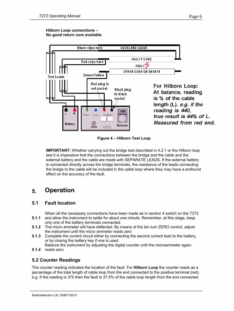
Hilborn Loop (figure 4) At the remote end of the cable the two auxiliary conductors are connected to one of the faulty phases. At the test end the same faulty conductor is connected to the RED bridge conductor terminal, and one conductor from the auxiliary cable is connected to the BLACK bridge conductor terminal. The external battery is connected between the faulty conductor and the second auxiliary conductor, initially connect only one side of the battery. The resistance of the auxiliary conductors (r) is not too critical, one is included in the battery circuit where the only effect will be to reduce the current, and the other appears in the bridge circuit where its effect should be negligible.
R2At balance (see section 5) X= x L R1 + R2 +r (R
1 + R
2 = Total resistance of potentiometer = 1000 Ω: small values of r will not make much
difference).
If necessary an adjustment can be made as follows: Reading
Correct x% = 1000 + r X 100%
In the example shown in Fig.4 x = 440, if r=10 ohm, then:
440 X 100%
Radiodetection Ltd. 00
Correct % =
1010901183-5
T272 Operating Manual
Page 6
Hilborn Loop connections – No good return core available
Figure 4 – Hilborn Test Loop
IMPORTANT: Whether carrying out the bridge test described in 4.2.1 or the Hilborn loop test it is imperative that the connections between the bridge and the cable and the external battery and the cable are made with SEPARATE LEADS. If the external battery is connected directly across the bridge terminals, the resistance of the leads connecting the bridge to the cable will be included in the cable loop where they may have a profound effect on the accuracy of the fault.
5. Operation
5.1
Fault location
5.1.1 When all the necessary connections have been made as in section 4 switch on the T272 and allow the instrument to settle for about one minute. Remember, at this stage, keep only one of the battery terminals connected.
5.1.2 The micro ammeter will have deflected. By means of the ten turn ZERO control, adjust the instrument until the micro ammeter reads zero
5.1.3 Complete the current circuit either by connecting the second current lead to the battery, or by closing the battery key if one is used.
5.1.4 Balance the instrument by adjusting the digital counter until the microammeter again reads zero.
5.2 Counter Readings The counter reading indicates the location of the fault. For Hilborn Loop the counter reads as a percentage of the total length of cable loop from the end connected to the positive terminal (red). e.g. If the reading is 375 then the fault is 37.5% of the cable loop length from the end connected
Radiodetection Ltd. 00901183-5
T272 Operating Manual
Page 7
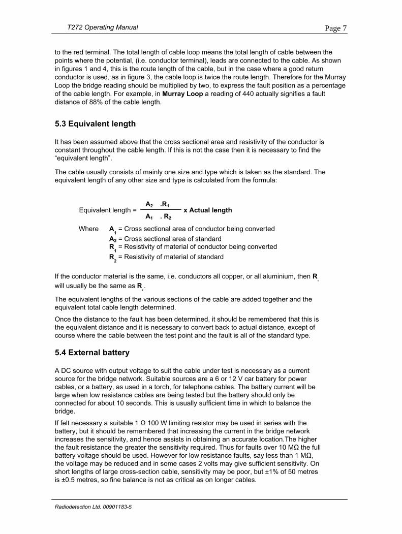
to the red terminal. The total length of cable loop means the total length of cable between the points where the potential, (i.e. conductor terminal), leads are connected to the cable. As shown in figures 1 and 4, this is the route length of the cable, but in the case where a good return conductor is used, as in figure 3, the cable loop is twice the route length. Therefore for the Murray Loop the bridge reading should be multiplied by two, to express the fault position as a percentage of the cable length. For example, in Murray Loop a reading of 440 actually signifies a fault distance of 88% of the cable length.
5.3 Equivalent length It has been assumed above that the cross sectional area and resistivity of the conductor is constant throughout the cable length. If this is not the case then it is necessary to find the “equivalent length”.
The cable usually consists of mainly one size and type which is taken as the standard. The equivalent length of any other size and type is calculated from the formula:
Equivalent length =
Where A1 = Cross
A2 = CrossR
1 = Resis
R2 = Resis
If the conductor material is thwill usually be the same as R
The equivalent lengths of theequivalent total cable length d
Once the distance to the faulthe equivalent distance and itcourse where the cable betw
5.4 External battery A DC source with output voltasource for the bridge networkcables, or a battery, as used large when low resistance caconnected for about 10 seconbridge.
If felt necessary a suitable 1 Ωbattery, but it should be remeincreases the sensitivity, andthe fault resistance the greatebattery voltage should be usethe voltage may be reduced ashort lengths of large cross-sis ±0.5 metres, so fine balanc
Radiodetection Ltd. 00901183-5
2 1A .R
x Actual lengthA1 . R2
sectional area of conductor being converted sectional area of standard tivity of material of conductor being converted tivity of material of standard
e same, i.e. conductors all copper, or all aluminium, then R1
2 .
various sections of the cable are added together and the etermined.
t has been determined, it should be remembered that this is is necessary to convert back to actual distance, except of een the test point and the fault is all of the standard type.
ge to suit the cable under test is necessary as a current . Suitable sources are a 6 or 12 V car battery for power in a torch, for telephone cables. The battery current will be bles are being tested but the battery should only be ds. This is usually sufficient time in which to balance the
100 W limiting resistor may be used in series with the mbered that increasing the current in the bridge network hence assists in obtaining an accurate location.The higher r the sensitivity required. Thus for faults over 10 MΩ the full d. However for low resistance faults, say less than 1 MΩ, nd in some cases 2 volts may give sufficient sensitivity. On
ection cable, sensitivity may be poor, but ±1% of 50 metres e is not as critical as on longer cables.
T272 Operating Manual
Page 8
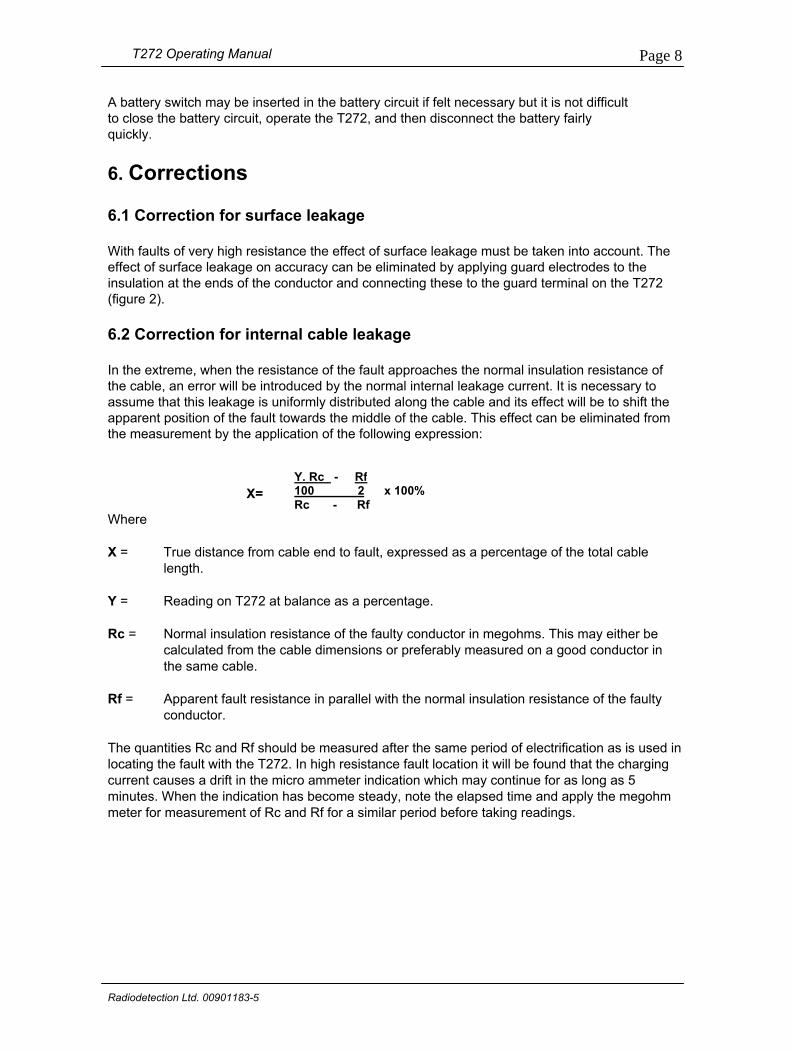
A battery switch may be inserted in the battery circuit if felt necessary but it is not difficult to close the battery circuit, operate the T272, and then disconnect the battery fairly quickly. 6. Corrections 6.1 Correction for surface leakage With faults of very high resistance the effect of surface leakage must be taken into account. The effect of surface leakage on accuracy can be eliminated by applying guard electrodes to the insulation at the ends of the conductor and connecting these to the guard terminal on the T272 (figure 2). 6.2 Correction for internal cable leakage In the extreme, when the resistance of the fault approaches the normal insulation resistance of the cable, an error will be introduced by the normal internal leakage current. It is necessary to assume that this leakage is uniformly distributed along the cable and its effect will be to shift the apparent position of the fault towards the middle of the cable. This effect can be eliminated from the measurement by the application of the following expression:
Y. Rc - Rf100 2 x 100%
Where
X = True distancelength.
Y = Reading on T
Rc = Normal insulcalculated frothe same cab
Rf = Apparent fauconductor.
The quantities Rc andlocating the fault with tcurrent causes a drift iminutes. When the indmeter for measuremen
Radiodetection Ltd. 009011
X=
Rc - Rffrom cable end to fault, expressed as a percentage of the total cable
272 at balance as a percentage.
ation resistance of the faulty conductor in megohms. This may either be m the cable dimensions or preferably measured on a good conductor in le.
lt resistance in parallel with the normal insulation resistance of the faulty
Rf should be measured after the same period of electrification as is used in he T272. In high resistance fault location it will be found that the charging n the micro ammeter indication which may continue for as long as 5 ication has become steady, note the elapsed time and apply the megohm t of Rc and Rf for a similar period before taking readings.
83-5
T272 Operating Manual
Page 9
7. Application Notes
1. For best results precautions should be taken to protect against secondary leakage paths, particular attention being paid to the battery and its leads. A vehicle battery may have a low insulation resistance housing and it should therefore stand on a good insulator. In the case of faults greater than one MΩ, the battery, T272, and test leads should all be insulated from earth by separate sheets of a good insulating material such as polyethylene. It may also be advisable for the operator to insulate himself from earth by standing on a sheet of insulating material when the T272 is being balanced and, if he is wearing easily charged clothing such as nylon, he should stand still. 2. When locating very high resistance faults, movement of personnel in the vicinity of the test equipment or the cable can cause a transient disturbance of the meter, making it difficult to obtain a reading. This is caused by electrostatic charges on their clothing and they should stand still whilst the measurement is being made. 3. Owing to the high sensitivity of the T272 a balance can often be obtained on a sound conductor. This balance is due to the normal cable leakage current and will result in a reading of approximately 50% in a cable of uniform insulation quality at a uniform temperature. For this reason the existence of the fault should be established by insulation resistance measurement before attempting to locate.
8. Maintenance 8.1 Instrument battery The T272 is powered by an internal 9 V battery mounted in a compartment within the instrument. To gain access for replacement, remove the central screws in the base of the instrument housing and lift out the battery lid. The battery leads are fitted with twin miniature press-stud connectors for correct polarity. Replace with PP3 (MN1604) alkaline battery.
The battery may be checked in position by operating the BATTTEST switch on the top panel. A reading on the micro ammeter of 20 or above is satisfactory for the correct operation of the instrument.
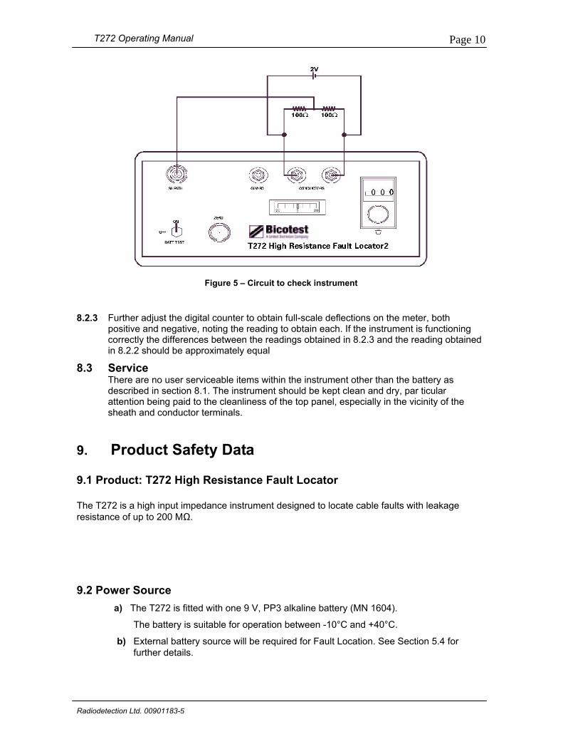
8.2 Instrument check The circuit shown in figure 5 may be used as a simple method of checking that the T272 is functioning correctly. Connect as shown and carry out the following steps.
8.2.1 With the 2 V battery disconnected, adjust the ZERO control until the meter reads zero. 8.2.2 Connect the 2-volt battery and adjust the digital counter for zero reading on the meter.
Note the reading on the counter, which should be approximately 500 (50%).
Radiodetection Ltd. 00901183-5
T272 Operating Manual
Page 10
Figure 5 – Circuit to check instrument 8.2.3 Further adjust the digital counter to obtain full-scale deflections on the meter, both
positive and negative, noting the reading to obtain each. If the instrument is functioning correctly the differences between the readings obtained in 8.2.3 and the reading obtained in 8.2.2 should be approximately equal
8.3 Service There are no user serviceable items within the instrument other than the battery as
described in section 8.1. The instrument should be kept clean and dry, par ticular attention being paid to the cleanliness of the top panel, especially in the vicinity of the sheath and conductor terminals.
9. Product Safety Data 9.1 Product: T272 High Resistance Fault Locator The T272 is a high input impedance instrument designed to locate cable faults with leakage resistance of up to 200 MΩ.
9.2 Power Source a) The T272 is fitted with one 9 V, PP3 alkaline battery (MN 1604).
The battery is suitable for operation between -10°C and +40°C.
b) External battery source will be required for Fault Location. See Section 5.4 for further details.
Radiodetection Ltd. 00901183-5
T272 Operating Manual
Page 11
9.3 Routine Servicing We recommended that the T272 is serviced and aligned by qualified personnel according to our technical service manual. Alternatively the equipment can be returned to Radiodetection for performance verification. 9.4 Transporting and Handling Parts made of metal and other hard materials are included in the construction of the units. Whilst unnecessary sharp points and edges have been avoided in the design, care must still be taken in handling the product to avoid minor cuts or abrasions.
9.5 Composition/Toxic Hazards In its normal condition the T272 presents no toxic hazards, however, in certain circumstances the following could apply:
a) Incineration Some of the electronic components included in the assembly are constructed with resins and other chemicals that give off toxic fumes upon incineration.
b) Acidic or Caustic Compounds Some of the components, particularly polystyrene and electrolytic capacitors included in the assembly are constructed with acidic of caustic compounds. In the event of damaged items coming into contact with the skin, washing the affected areas with cold water is recommended.
Should eyes be rubbed by hands contaminated with the above compounds, the eyes must be thoroughly rinsed with clean water and medical attention sought urgently.
c) Physical Damage Some of the components (especially some types of semiconductors, relays and capacitors) may contain very small quantities of toxic materials that could present a remote but potential hazard once they become physically damaged. As a general precaution avoid unnecessary contact with damaged compounds and dispose them carefully.
9.6 Disposal Take reasonable precautions that are normally exercised with the disposal of electrical/ electronic equipment. If in doubt contact your local authority.
9.7 Safe Use The T272 is designed to be used by suitably trained personnel conforming with procedures and instructions described in this Operating Manual. It should be noted that the operation of T272 does not demand the wearing of protective clothing or any additional personnel protection. However, site conditions may dictate otherwise.
Radiodetection Ltd. 00901183-5

World leaders
Technical support
Servicing and repair
Training
Radiodetection is a proud member of the SPX group of companies, which provide technical products and service solutions worldwide.
Radiodetection and its associated companies specialize in the design and manufacture of products for the location and maintenance of underground pipes and cables. Our aim is to be viewed as the supplier of choice of ‘high performance’ quality equipment using advanced product technologies. We are also committed to both design innovation and customer support.
Radiodetection equipment users have easy access to technical support. A call to your regional representative, or the Radiodetection head office, will put you in contact with our team of field-experienced technical experts.
Radiodetection has a team of factory-trained service technicians and dedicated service facilities. Turnaround is fast, and costs are very competitive.
Product training for your operators and training personnel is available on your site, or at Radiodetection’s headquarters. Training is with qualified instructors and each trainee receives a certificate to confirm they have received the training.
AmericaRadiodetection 154 Portland Road Bridgton, ME 04009, USA Tel: +1 (207) 647 9495 Toll Free: +1 (877) 247 3797 Fax: +1 (207) 647 9496 Email: [email protected] Web: www.radiodetection.com
Pearpoint 72055 Corporate Way Thousand Palms CA 92276, USA Tel: +1 800 688 8094 Tel: +1 760 343 7350 Fax: +1 760 343 7351 Email: [email protected] Web: www.radiodetection.com
Radiodetection (Canada) 344 Edgeley Boulevard, Unit 34 Concord, Ontario L4K 4B7, Canada Tel: +1 (905) 660 9995 Toll Free: +1 (800) 665 7953 Fax: +1 (905) 660 9579 Email: [email protected] Web: www.radiodetection.com
EuropeRadiodetection Ltd (UK) Western Drive Bristol BS14 0AF, UK Tel: +44 (0) 117 976 7776 Fax: +44 (0) 117 976 7775 Email: [email protected] Web: www.radiodetection.com
Radiodetection (France) 13 Grande Rue, 76220 Neuf Marché, France Tel: +33 (0) 232 8993 60 Fax: +33 (0) 235 9095 58 Email: [email protected] Web: http://fr.radiodetection.com
Radiodetection (Benelux) Industriestraat 11 7041 GD ’s-Heerenberg, Netherlands Tel: +31 (0) 314 66 47 00 Fax: +31 (0) 314 66 41 30 Email: [email protected] Web: http://nl.radiodetection.com
Radiodetection (Germany) Groendahlscher Weg 118 46446 Emmerich am Rhein, Germany Tel: +49 (0) 28 51 92 37 20 Fax: +49 (0) 28 51 92 37 520 Email: [email protected] Web: http://de.radiodetection.com
Asia-PacificRadiodetection (Asia-Pacific) Room 708, CC Wu Building 302-308 Hennessy Road, Wan Chai Hong Kong SAR, China Tel: +852 2110 8160 Fax: +852 2110 9681 Email: [email protected] Web: www.radiodetection.com
Radiodetection (China) Hongfu Mansion, Room 61622 Zheng Ge Zhuang, Bei Qi Jia Town Chang Ping District Beijing 102209, China Tel: +86 (0) 10 8975 5540 Fax: +86 (0) 10 8975 5640 Email: [email protected] Web: http://cn.radiodetection.com
Radiodetection (Australia) Unit 14, 5-7 Prosperity Parade Warriewood NSW 2102, Australia Tel: +61 (0) 2 9979 8555 Fax: +61 (0) 2 9979 7733 Email: [email protected] Web: www.radiodetection.com
Radiodetection products are under continuous development and are subject to change, we reserve the right to alter or amend any published specification without notice.Copyright 2008 Radiodetection Ltd. - SPX Corporation. All rights reserved. Radiodetection Ltd. is a subsidiary of SPX Corporation.
www.radiodetection.com
To see the full range of products and services provided by Radiodetection visit: