High-Pressure Pumps for Fire Fighting, type PAHF … DKCFN.PD.010.A1.02 521B1113 Data sheet...
19
521B1113 DKCFN.PD.010.A1.02 03-2010 Data Sheet High-Pressure Pumps for Fire Fighting, type PAHF 20/25/32/40 with dedicated valves: relief valve (type VRHF), relief/bypass valve (type VPHF) and check valve (type VCH) The PAHF pumps are especially designed for the high-pressure fire extinguishing industry. It is dedicated for the water mist market for both land and marine applications. The pumps are designed for operation on tap water and the size ranges from 20 ccm/rev to 40 ccm/rev and can provide a flow from 14 to 115 l/min (3,7 to 30,3 gpm). Two types of valves are designed for direct mounting on the pump, depending on the specific need: a check valve and a relief valve. The axial piston principle provides very high effi- ciency, small and compact design and long service life. The Danfoss pumps are water lubri- cated and do not involve any other lubricant, making this unique pump maintenance free over its entire service life. Introduction Features • Very compact and light pump (can be installed with direct coupling to an electric motor/combustion engine) • Generates insignificant pulsations in the pressure line • No preventive maintenance required (no periodic service like eg change of lubricant and wear parts) • Service life 500 hours • All parts of the pump are made of noncorrosive material and the surface is easy to clean • Few wearing parts • Pumps can be directly boosted, without the need of a tank Lenntech [email protected] Tel. +31-152-610-900 www.lenntech.com Fax. +31-152-616-289
-
Upload
nguyenhanh -
Category
Documents
-
view
216 -
download
0
Transcript of High-Pressure Pumps for Fire Fighting, type PAHF … DKCFN.PD.010.A1.02 521B1113 Data sheet...

521B1113 DKCFN.PD.010.A1.02 03-2010
Data Sheet
High-Pressure Pumps for Fire Fighting, type PAHF 20/25/32/40with dedicated valves: relief valve (type VRHF), relief/bypass valve (type VPHF)
and check valve (type VCH)
The PAHF pumps are especially designed for the high-pressure fi re extinguishing industry. It is dedicated for the water mist market for both land and marine applications. The pumps are designed for operation on tap water and the size ranges from 20 ccm/rev to 40 ccm/rev and can provide a fl ow from 14 to 115 l/min (3,7 to 30,3 gpm).
Two types of valves are designed for direct mounting on the pump, depending on the
specifi c need: a check valve and a relief valve.
The axial piston principle provides very high effi -ciency, small and compact design and longservice life. The Danfoss pumps are water lubri-cated and do not involve any other lubricant, making this unique pump maintenance free over its entire service life.
Introduction
Features • Very compact and light pump (can be installed with direct coupling to an electric motor/combustion engine)
• Generates insignifi cant pulsations in the pressure line
• No preventive maintenance required (no periodic service like eg change of lubricant and wear parts)
• Service life 500 hours
• All parts of the pump are made of noncorrosive material and the surface is easy to clean
• Few wearing parts
• Pumps can be directly boosted, without the need of a tank
[email protected] Tel. +31-152-610-900www.lenntech.com Fax. +31-152-616-289

2 DKCFN.PD.010.A1.02 521B1113
Data sheet High-Pressure Pumps for Fire extinguishing market, type PAHF
Application examples
Technical data
Motor dimensions
Pump size 20 25 32 40
Geometric displacement cm3/rev
20 25 32 40
Max. pressure cont., bar/psi
160 160 160 160
Boosted
Max speed rpm3600 3600 3600 3000
Tank supply
Max. speed, rpm1800 1800 1800 1800
Min. speed rpm 700 700 700 700Weight, stainless kg/lbs 15,6/34,4 15,6/34,4 15,6/34,4 15,6/34,4Typical 4-pole motor size at max. pressure in 1500 rpm (kW)1800 rpm (HP)
1115
1520
1525
18,530
Typical 2-pole motorsize at max. pressure in3000 rpm (kW)3600 rpm (HP)
18,530
3040
3050
37--
The PAHF pump can be used in both land and marine segments within the high-pressure water mist fi re fi ghting market. For the marine based applications, our pump is suitable for eg:
• Machine room protection, • Accommodations • Local area protection• etc.
For land based applications, our pump can be used almost anywhere eg:
• Airports• Hotels• Garages• Tunnels • Offi ces• Warehouses• Production sites • Schools • etc.
Required motor power:From the following table you can determine the rpm of the pump at the desired fl ow. Calculate as follows: Speed [in rpm] × displacement per rev [in ccm] × pressure [in bar]P [in kW] = ––––––––––––––––––––––––––––––––––––––––––––––––––––––– 600.000 × η mech (mechanical effi ciency)
The required torque is calculated as follows: Displacement [in ccm] × pressure [in bar]M [in Nm] = –––––––––––––––––––––––––––––––––– 62.8 × η mech (mechanical effi ciency)
To determine the correct motor size, both the power and torque requirement must be verifi ed.
The mechanical effi ciency of the pump is estimated as follows:PAH 20, 25, 32, 40 0.9

521B1113 DKCFN.PD.010.A1.02 3
Data sheet High-Pressure Pumps for Fire extinguishing market, type PAHF
Flow calculation
Typical fl ow at diff erent pressures in litres per minute
• Theoretical fl ow: Q (th) [l/min] = pump displacement in cm3 × rpm/1000 • Flow at max. pressure: The fl ow at max. pressure Q (p max) is shown in the table.• Flow at any pressure: At zero pressure the true fl ow equals the theoretical fl ow Q (th).• The fl ow (Q eff ) at less than max. pressure (pmax) can be calculated with the following equation: Q eff = Q (th) – [(Q (th) – Q (p max)) × ( p / pmax )]
100 bar PAHF 20 PAHF 25 PAHF 32 PAHF 40
Typical fl ow 1500 rpm 28,6 36,1 45,9 56,8Typical fl ow 3000 rpm 57,9 73,1 93,4 115,3Typical fl ow 3600 rpm 70,0 88,1 112,0
140 bar PAHF 20 PAHF 25 PAHF 32 PAHF 40
Typical fl ow 1500 rpm 28,0 35,4 45,6 56,7Typical fl ow 3000 rpm 57,5 72,4 93,3 115,3Typical fl ow 3600 rpm 69,0 87,1 112,0
160 bar PAHF 20 PAHF 25 PAHF 32 PAHF 40
Typical fl ow 1500 rpm 27,5 35,2 45,4 56,3Typical fl ow 3000 rpm 56,9 71,9 92,9 114,8Typical fl ow 3600 rpm 68,4 87,2 111,5

4 DKCFN.PD.010.A1.02 521B1113
Data sheet High-Pressure Pumps for Fire extinguishing market, type PAHF
Inlet pressure
Temperature
Shaft load
Noise level
Filtration
Water Quality
The pump is neither to be exposed to axial nor radial loads. We therefore recommend using a fl exible coupling for connection to the electric motor or the combustion engine.
Since the pump typically is mounted on a bell housing or frame, the noise level can only be deter-mined for the complete unit (system). It is therefore very important that the pump is mounted cor-rectly on a frame with dampers to minimize vibrations and noise. Furthermore, the pump discharge should be connected with the application ie with a fl exible high-pressure hose.
The noise level is infl uenced by:• The speed of the pump, high rpm creates more noise than low rpm.• The discharge pressure, high pressure generates more noise than low pressure.• Rigid mounting of the pump generates more noise than fl exible mounting.• Pipe mounting direct to the pump increases the noise level compared to a fl exible hose.
The applied water must be fi ltered through a 10 μ absolute, β10 value > 5000 fi lter. In open-ended systems (continuous supply of ”fresh” water) the fi lter must be placed before the pump or the tank to ensure continuous fi ltration.For further fi lter details, please contact the High-Pressure Pumps Sales Organization.
Fluid temperature: • Min. +3° C, max. 50° C at max. cont. pressure• Min. +3° C, max. 60° C at max. 100 bar
Ambient temperature: • Min. 0° C to max. 50° C
Storage temperature: • Min. -40° C to max. 70° C
For operation at lower temperatures than +3°C, please see the paragraph on antifreeze protection and contact Danfoss High-Pressure Pumps sales organization for High-Pressure Pumps. For operation at higher temperatures, please contact the High-Pressure Pumps sales organization.
Water of drinking water quality, confi rming to the EEC directive 98/83/EC.Please contact Danfoss High-Pressure Pumps sales organization in case of doubt.
PAHF is designed to operate under boosted pressure supply conditions. The boost pressure is recom-mended to be between 1-6 bar (14,5-87 psi) (2-7 bar (43,5 - 101,5 psi) abs).Please make use of the integrated 1/4" gauge ports (inlet) with appropriate pressure switches for monitoring the supply pressure accordingly.
Short term inlet pressure peaks must not exceed 30 bar (435 psi). Max 10 bar (145 psi) during static standstill.It is recommended that the normal boost pressure is 1-6 bar (14,5-87 psi).
If the peak inlet pressure is unknown, a 15 bar (217,5 psi) safety relief valve should be installed on the inlet side of the pump.
Outlet pressureMax. pressure on the pump's outlet line should be limited at 160 bar (2320 psi) continuously.Short-term pressure peaks (e.g. in connection with closing of a valve) of up to 200 bar (2900 psi) are acceptable.
It is recommended to have a check valve on the outlet side of the pump to protect the pump from high pressure going backwards into the pump when turned off ; especially, when using fl exible hose or more pumps are installed in the same system.

521B1113 DKCFN.PD.010.A1.02 5
Data sheet High-Pressure Pumps for Fire extinguishing market, type PAHF
Corrosion and antifreeze protection
Corrosion protection
Service
Code number Pump size Code number
PAHF 20 180B0092PAHF 25 180B0093PAHF 32 180B0094PAHF 40 180B0095
If the pump is exposed to temperatures below freezing, it must be protected against freezing.See also paragraph on Operation Conditions.
Danfoss recommends DOWCAL N or CHILLSAFE antifreezes both being a biologically degradable Mono Propylene Glycol.
(DOWCAL N is produced by POLO).(CHILLSAFE is produced by ATCO).
Producers of DOWCAL N and CHILLSAFE recom-mend a mixture ratio of min. 30% DOWCAL N/CHILLSAFE to prevent biofi lm occurrence in the system due to DOWCAL N and CHILLSAFE being biologically de-gradable.
If the system is decommissioned for more than 4 weeks or in transportation, the pump must be preserved against corrosion. Never just drain the pump!
See instructions delivered with the pump.
The PAHF pumps are maintenance free over their entire service life. To achieve the maximum service life, proper water supply and fi ltration are mandatory.

6 DKCFN.PD.010.A1.02 521B1113
Data sheet High-Pressure Pumps for Fire extinguishing market, type PAHF
Dimensions
521B1113 DKCFN.PD.010.A1.02 7
Data sheet High-Pressure Pumps for Fire extinguishing market, type PAHF
Systems can be either: Open-ended systems with water supply from a tank.Open-ended systems with direct water-supply (boosted pressure).
The design of the system must ensure that self-emptying of the pump during standstill is avoided.
The minimum boost pressure is 1 bar (14,5 psi), and the maximum peak pressure is 30 bar (435 psi). The recommended normal boost pressure is 1-6 bar atm (14,5-87 psi). Max 10 bar (145 psi) during static standstill. The inlet pressure of the pump must never exceed the outlet pressure. This may typically occur in boosted or open-ended systems with supply direct from the tap and where a bypass valve is activated.
System design
Open-ended systems,water supply from tank
Open-ended systems with direct water supply
(The numbers 1- 3 refer to the drawing below)In order to eliminate the risk of cavitation, observe the following guidelines:
1) Place the tank above the pump (water level in the tank should always be above the pump).
2) Place the inlet fi lter before the tank.
3) Dimension the inlet line to obtain minimum pressure loss (large fl ow area, minimum pipe length, minimum number of bends/connections, fi ttings with small pressure losses).
The inlet line connection must be properly tightened, as possible entrance of air will cause cavitation.
Water tankMust be made of corrosion-proof material such as stainless steel or plastic and must be sealed to prevent entrance of impurities from the environment.
Automatic pressure equalization between tank and surroundings must be ensured.Inlet from the water supply (the return line) and inlet to the pump should be placed in opposite ends of the tank to calm and deaerate the water, and to ensure optimum op-portunity for particles to settle.
The pump is supplied with water direct from the water supply or from a booster pump. Recommended normal boost pressure is 1-6 bar (14,5-87 psi)
8 DKCFN.PD.010.A1.02 521B1113
Data sheet High-Pressure Pumps for Fire extinguishing market, type PAHF
max
0,2
5 m
mm
ax. 0
,01
inch
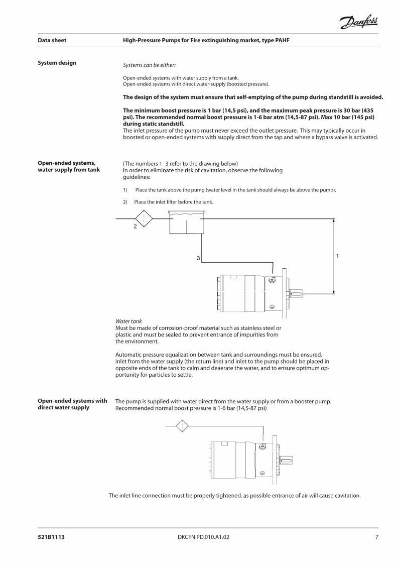
Is indicated by means of an arrow at the inlet side of the pump.
CCW (counter clockwise) CW (clockwise)
Building up the pump unit
Mounting
Direction of rotation
Orientation
If alternative mounting is desired, please contact the Danfoss High-Pressure Pumps sales organization.
Choose proper tolerances to ensure an easy mounting of the elastic coupling without use of tools.
Please take care to observe the recommended length tolerances of the chosen coupling, as an axial force on the pump shaft will prevent the pump from generating pressure (and over time damage the pump).
A: Elastic couplingB: Bell housing C: Motor shaft
The pump can be mounted/orientated in any horizontal position and it can be mounted/orientated in the vertical position with the shaft upwards. The pump cannot be vertically mounted/orientated with the shaft facing downwards.
3 mm

521B1113 DKCFN.PD.010.A1.02 9
Data sheet High-Pressure Pumps for Fire extinguishing market, type PAHF
Protection from too high system pressures
The pump should be protected against too high pressure by means of a pressure relief valve or a bypass/unloading valve placed on the pressure side
The valve should be placed as close to the pump as possible.
The opening characteristics of the valve must not result in peak pressures higher than 200 bar (2900 psi).
Protection from too high system pressures
Connections
C
I
X0
O
CXI
PAHF 20/25/32/40Outlet (O) Inlet (I) Bleeding (C) Gauge
Thread, ISOUse PAHF adaptor or VRHF100 Relief valve
(thread size 3/4" BSPP)
1 1/4” BSPP with 20mm long thread
M6 (width across fl at =
5mm)
1/4” BSPP with 15mm long
thread
Max tighten torqueScrews for
adaptor block valves: 4 pcs M8 30Nm
150 Nm*(133 lb (f ) ft)
4Nm*(3 lb (f ) ft)
15 Nm*(11 lb (f ) ft)
I : InletO : OutletC : Bleeding XI: Gauge port inlet *XO: Gauge port outlet**Parallel key: 8 × 7 × 32 DIN 6885
*There is one 1/4” ports on the inlet side for optional mounting of ie switches for low pressure and temperature. **There is one 1/4” port on the outlet for optional mounting of ie pressure transducer.
• Recommended torque values refer to steel washers containing a rubber sealing element.
10 DKCFN.PD.010.A1.02 521B1113
Data sheet High-Pressure Pumps for Fire extinguishing market, type PAHF
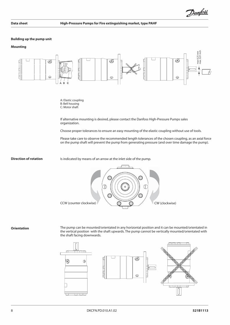
Before start-up, loosen the upper bleeding plug. When water appears from the bleeding plug, retighten the plug.
The piping/hose between inlet fi lter and pump must be fl ushed prior to initial start up of the pump to ensure that impurities are removed.
Warning:Make sure that the direction of rotation of the electric motor corresponds to the direction of rotation of the pump.
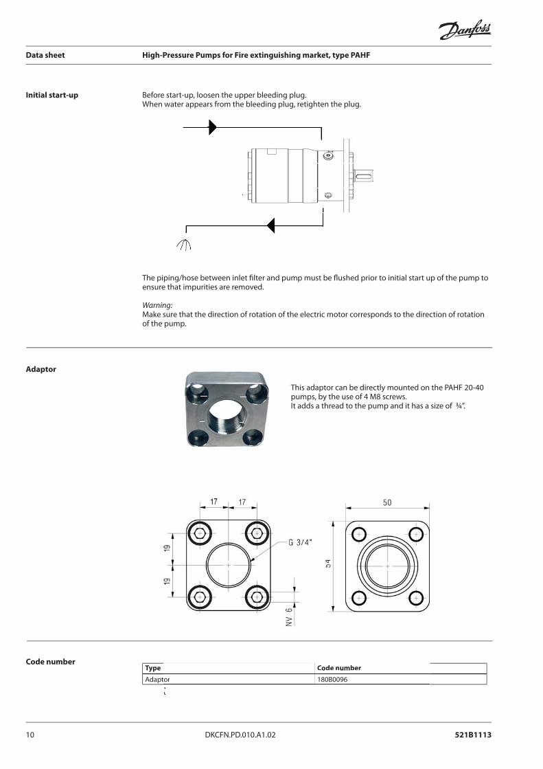
Type Code number
Adaptor 180B0096
Initial start-up
Adaptor
Code numberCode number
or 180B0096
This adaptor can be directly mounted on the PAHF 20-40 pumps, by the use of 4 M8 screws. It adds a thread to the pump and it has a size of ¾”.

521B1113 DKCFN.PD.010.A1.02 11
Data sheet High-Pressure Pumps for Fire extinguishing market, type PAHF
Type VRHF 100
Design and function
Features
Fluid
Code number
Relief valve for mounting directly on the PAHF pumps
This relief valve can be directly mounted on the PAHF 20-40 pumps, by the use of 4 M8 screws. It adds a thread to the pump and it has a size of ¾”.The relief valve is used for protecting the components of a system against overload as a result of a pressure peak.Further, the valve is designed for controlling/limiting the system pressure by draining off the sur-plus water from the pressure side. The valve is designed for tap water, ie without additives of any kind to the medium. (EU-drinking water directive 98/83/EC).
• Excellent functional characteristics.• Easy-to-clean surface.• Corrosion-proof parts (stainless steel, AISI 304, W. No. 1.4301).
The water must be clean (according to the EU drinking water directives 98/83/EC) and must be free from sediments.
Type Code number
VRHF 100 180G0011

12 DKCFN.PD.010.A1.02 521B1113
Data sheet High-Pressure Pumps for Fire extinguishing market, type PAHF
P/Q Characteristic
0
20
40
60
80
100
120
140
160
180
0 10 20 30 40 50 60 70 80 90 100
Q [l/min]
P [
ba
r] 140bar-10l/min
80bar- 10/min
Technical dataUnit VRHF100
Pressure setting bar 80-140Setting screw, from min. to max. mm 6,2Flow (max.) l/min 100Temperature fl uid (max. oC) oC 50Temperature ambient (max. oC) oC 50Internal leakage 20% below max. set-ting pressure l/min up to 1.0
FiltrationWeight kg 2,8
10μ abs. β10 >5000
Pressure setting range: 80 - 140 bar
80 to 140 bar
140 bar - 10 l/min 80 bar - 10 l/min
521B1113 DKCFN.PD.010.A1.02 13
Data sheet High-Pressure Pumps for Fire extinguishing market, type PAHF
Xo XR
XRT
Xo
XR
RETURN
FLOW DIRECTION
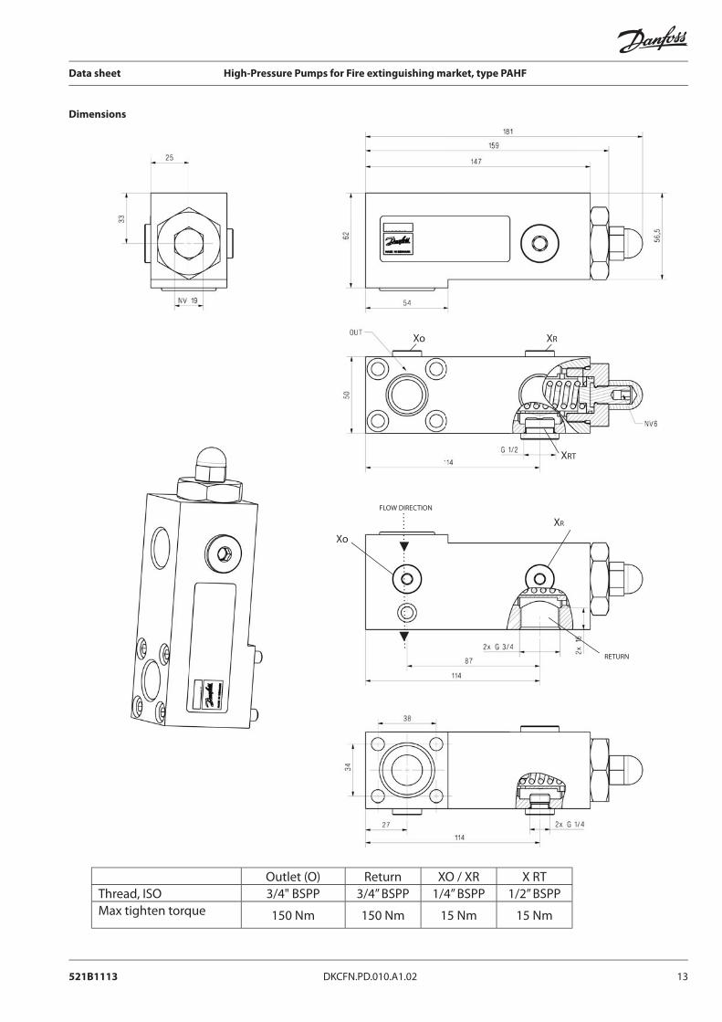
Dimensions
Outlet (O) Return XO / XR X RTThread, ISO 3/4" BSPP 3/4” BSPP 1/4” BSPP 1/2” BSPPMax tighten torque 150 Nm 150 Nm 15 Nm 15 Nm
14 DKCFN.PD.010.A1.02 521B1113
Data sheet High-Pressure Pumps for Fire extinguishing market, type PAHF
Type VPHF 100
Design and function
Features
Fluid
Code number
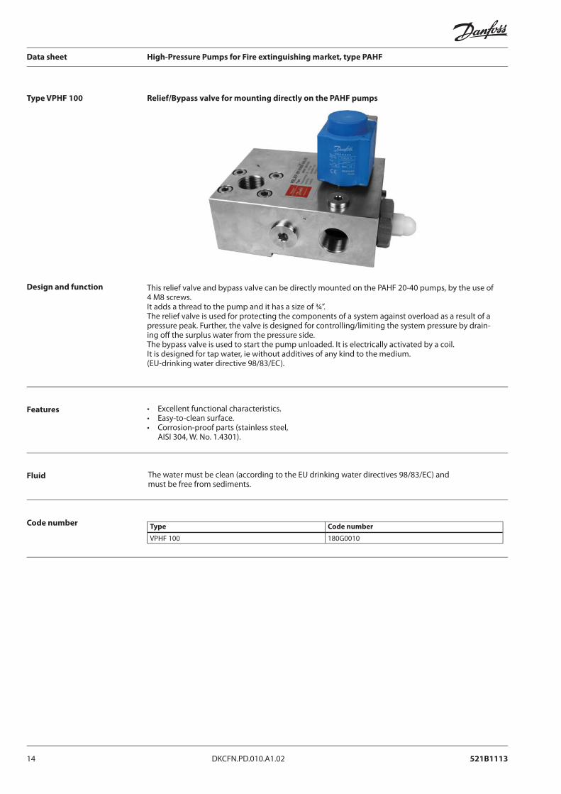
Relief/Bypass valve for mounting directly on the PAHF pumps
This relief valve and bypass valve can be directly mounted on the PAHF 20-40 pumps, by the use of 4 M8 screws.It adds a thread to the pump and it has a size of ¾”.The relief valve is used for protecting the components of a system against overload as a result of apressure peak. Further, the valve is designed for controlling/limiting the system pressure by drain-ing off the surplus water from the pressure side.The bypass valve is used to start the pump unloaded. It is electrically activated by a coil. It is designed for tap water, ie without additives of any kind to the medium.(EU-drinking water directive 98/83/EC).
• Excellent functional characteristics.• Easy-to-clean surface.• Corrosion-proof parts (stainless steel, AISI 304, W. No. 1.4301).
The water must be clean (according to the EU drinking water directives 98/83/EC) and must be free from sediments.
Type Code number
VPHF 100 180G0010

521B1113 DKCFN.PD.010.A1.02 15
Data sheet High-Pressure Pumps for Fire extinguishing market, type PAHF
P/Q Characteristic
0
20
40
60
80
100
120
140
160
180
0 10 20 30 40 50 60 70 80 90 100
Q [l/min]
P [
ba
r] 140bar-10l/min
80bar- 10/min
Technical data- relief valve
Unit VPHF100
Pressure setting bar 80-140Setting screw, from min. to max. mm 6,2Flow (max.) l/min 100Temperature fl uid (max. oC) oC 50Temperature ambient (max. oC) oC 50Internal leakage 20% below max. set-ting pressure l/min up to 1.0
FiltrationWeight kg 7
10μ abs. β10 >5000
Pressure setting range: 80 - 140 bar
80 to 140 bar
16 DKCFN.PD.010.A1.02 521B1113
Data sheet High-Pressure Pumps for Fire extinguishing market, type PAHF
Bypass valve
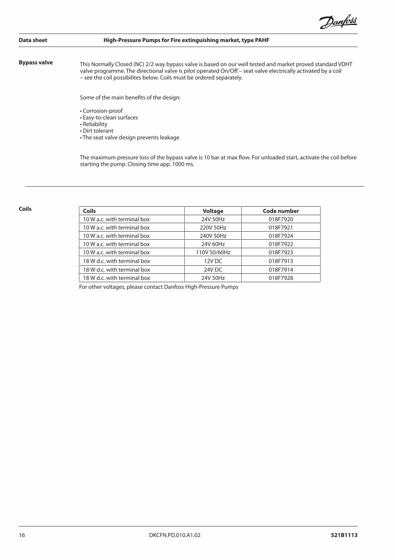
Coils Coils Voltage Code number
10 W a.c. with terminal box 24V 50Hz 018F792010 W a.c. with terminal box 220V 50Hz 018F792110 W a.c. with terminal box 240V 50Hz 018F792410 W a.c. with terminal box 24V 60Hz 018F792210 W a.c. with terminal box 110V 50/60Hz 018F792318 W d.c. with terminal box 12V DC 018F791318 W d.c. with terminal box 24V DC 018F791418 W d.c. with terminal box 24V 50Hz 018F7928
For other voltages, please contact Danfoss High-Pressure Pumps
This Normally Closed (NC) 2/2 way bypass valve is based on our well tested and market proved standard VDHT valve programme. The directional valve is pilot operated On/Off – seat valve electrically activated by a coil – see the coil possibilites below. Coils must be ordered separately.
Some of the main benefi ts of the design:
• Corrosion-proof• Easy-to-clean surfaces• Reliability• Dirt tolerant• The seat valve design prevents leakage
The maximum pressure loss of the bypass valve is 10 bar at max fl ow. For unloaded start, activate the coil before starting the pump. Closing time app. 1000 ms.

521B1113 DKCFN.PD.010.A1.02 17
Data sheet High-Pressure Pumps for Fire extinguishing market, type PAHF
Dimensions
521B1113 DKCFN.PD.010.A1.02 17
Outlet (O) Return XO / XR X RTThread, ISO 3/4" BSPP 3/4” BSPP 1/4” BSPP 1/2” BSPPMax tighten torque 150 Nm 150 Nm 15 Nm 15 Nm
FLOW DIRECTION
XRT
XR
XO
XO
RETURN
18 DKCFN.PD.010.A1.02 521B1113
Data sheet High-Pressure Pumps for Fire extinguishing market, type PAHF
This relief valve can be directly mounted on the PAHF 20-40 pumps, by the use of 4 M8 screws. It adds a thread to the pump and it has a size of ¾”.
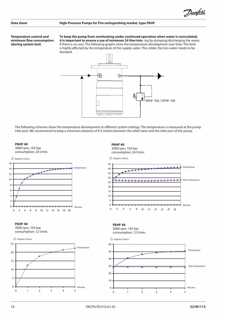
Temperature control and minimum fl ow consumption (during system test)
PAHF 403000 rpm, 105 barconsumption: 12 l/min.
PAHF 403000 rpm, 105 barconsumption: 12 l/min.
PAHF 403000 rpm, 105 barconsumption: 24 l/min.
PAHF 403000 rpm, 105 barconsumption: 24 l/min.
The following schemes show the temperature development at diff erent system settings. The temperature is measured at the pump inlet port. We recommend to keep a minimum distance of 0.5 metres between the relief valve and the inlet port of the pump.
VRHF 100 / VPHF 100
To keep the pump from overheating under continued operation when water is recirculated, it is important to ensure a use of minimum 24 liter/min. (eg by dumping/discharging the water, if there is no use). The following graphs show the temperature development over time. The limit is highly aff ected by the temperature of the supply water. The colder, the less water needs to be dumped.
0
2
4
6
8
10
12
14
16
0 2 4 6 8 10 12 14 16 18 20
Degrees Celsius
Temperature
0
5
10
15
20
25
30
35
40
45
0 2 4 6 8 10 12 14 16 18 20Minutes
Minutes
Temperature
Tank temperature
Degrees Celsius
0
5
10
15
20
25
0 1 2 3 4 5
Temperature
Minutes
Degrees Celsius
0
10
20
30
40
50
60
0 1 2 3 4 5
Minutes
Temperature
Tank temperature
Degrees Celsius

19 DKCFN.PD.010.A1.02 521B1113
Data sheet High-Pressure Pumps for Fire extinguishing market, type PAHF
Check valve type VCH
Code numbers
This valve is able to handle fl ows up to 150 l/m. It has port sizes of ¾” both in and out and it has a very low pressure loss of max. 2 bar.
Type Code number
VCH 180H0117
[email protected] Tel. +31-152-610-900www.lenntech.com Fax. +31-152-616-289