
High Pressure Hydrogen Tank Manufacturing
24
Department of Energy Workshop High Pressure Hydrogen Tank Manufacturing Mark Leavitt Quantum Fuel Systems Technologies Worldwide, Inc. August 11, 2011 This presentation does not contain any proprietary, confidential, or otherwise restricted information
Transcript of High Pressure Hydrogen Tank Manufacturing

Department of Energy Workshop
High Pressure Hydrogen Tank Manufacturing
Mark LeavittQuantum Fuel Systems Technologies Worldwide, Inc.
August 11, 2011
This presentation does not contain any proprietary, confidential, or otherwise restricted information

History of Innovations…Announced breakthrough in all-composite lightweight, high capacity, low-cost fuel storage technologies.
•Developed a series of robust, OEM compatible electronic control products.
Developed H2
storage system for SunLine Tran-sit Hythane®bus.
Awarded patent for integrated module including in-tank regulator
•Developed high efficiency H2 fuel storage systems for DOE Future Truck programs
Developed H2
storage and metering system for Toyota’s FCEV platform.
First to certify 10,000 psi systems in Japan
•Designed, developed and validated advanced fuel storage systems for DaimlerChrysler
First to fill a H2
storage cylinder with compressed H2
at 5,000 psi at California Fuel Cell Partnership developed for the Hyundai Santa Fe Fuel Cell Vehicle.
•Achieved a record of 11.3% H2 tank efficiency, the highest weight efficiency ever demonstrated, in partnership with Lawrence Livermore National Lab and Thiokol.
•Developed portable hydrogen refueling devices and supplied for multiple customer applications
Awarded patent for mobile hydrogen refueling systems
•Developed 13.3 wt% hydrogen tank and 0.75 kg regulatorfor NASA/ AeroVironment
Developed electrolyzer based H2 mobile refueling system for the US Army
•Developed on-tank automatic valve system for 10,000 psi H2
First to ship 10,000 psi H2 storage fuel system with patented in-tank regulator module
Validated H2
injectors and developed advanced hydrogen metering systems for FC stack
First to certify 10,000 psi H2 Storage Tank to International Standards.
Developed and implemented advanced process controls, based on experience in producing over 1,600 hydrogen tanks
•Awarded patent on injectors for dry gaseous fuels
•Opened state-of-the art SULEV emissions testing Facility.
1999 2000 2001 2002 2003First to demonstrate an all-composite H2
Storage Tank that stores at 10,000 psi
•Developed 10,000 psi in-tank pressure regulator module incorporating two regulators and solenoid valve
Developed FC hybrid electric “Aggressor” for the US Army, from the ground-up
•Developed ultra-light hydrogen systems for high altitude applications
•Opened world’s first 10,000 psi hydrogen gas test facility and performs extreme tests
Developed 2nd
generation in-tank regulation system for Toyota
•Developed an integrated plug-and-play fuel storage system for GM HyWire FC concept vehicle
Began developing additional H2 ICE hybrid platforms –to follow CNG and PHEV
•Launched R&D targeting next generation storage and metering systems
•Developed innovative Hydrogen ICE hybrid electric vehicles for SCAQMD
GM’s Sequel – First Hydrogen Fuel Cell vehicle to go 300 miles without refueling
2004 2005 2006 2007 2008 2009 2010
•Launched in production CNG (21x60) vessel lightest in class by 35%
Quantum and Fisker form: Fisker Automotive (Q-Drive)
First in the industry with drop in CNG tank replacement for HD diesel 25” & 26” tanks
Began development and verification of the Saturated Injector
2nd Generation Military Vehicle intro of Q-Force
Electrification of LLV – Quantum Quiet DriveTM 2

External Regulator 0 First Stage• 87.5 MPa max inlet pressure• 3 MPa nominal outlet pressure• EIHP Certified
Mid-Stage Valve• 3 MPa nominal working pressure• Electronically controlled shut-off valve
using PWM Peak and Hold current • Pressure gauge port• Auxiliary defueling port with integral flow
control orifice
Regulator – Second Stage• 3 MPa nominal inlet pressure• 500 kPaG nominal outlet pressure• Outlet pressure gauge port
Low Pressure Lock-off• Normally closed• 230 psig maximum working pressure• Maximum flow 5g/sec @ 10 psiD• Coil resistance 12 Ohms @ 25ºC• Normal operating voltage 9.6 to 16.5 VDC• Saturated current• Operating temperature -40ºC to 85ºC
H2 Fuel Systems
3
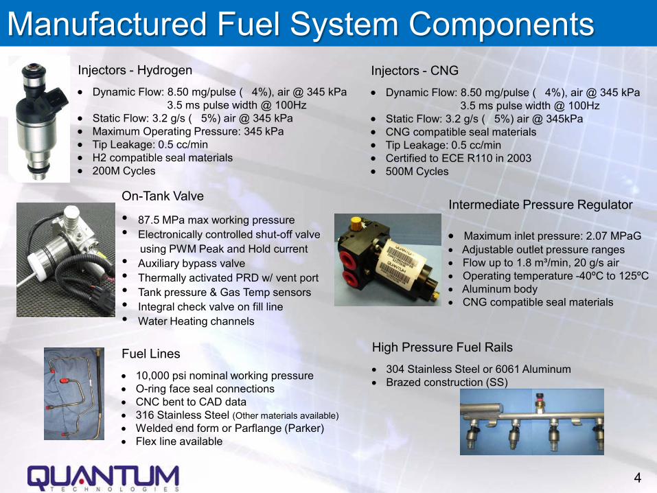
On-Tank Valve
• 87.5 MPa max working pressure• Electronically controlled shut-off valve
using PWM Peak and Hold current • Auxiliary bypass valve• Thermally activated PRD w/ vent port• Tank pressure & Gas Temp sensors• Integral check valve on fill line• Water Heating channels
Injectors - Hydrogen• Dynamic Flow: 8.50 mg/pulse ( 4%), air @ 345 kPa
3.5 ms pulse width @ 100Hz• Static Flow: 3.2 g/s ( 5%) air @ 345 kPa• Maximum Operating Pressure: 345 kPa• Tip Leakage: 0.5 cc/min• H2 compatible seal materials• 200M Cycles
Fuel Lines• 10,000 psi nominal working pressure• O-ring face seal connections• CNC bent to CAD data• 316 Stainless Steel (Other materials available)• Welded end form or Parflange (Parker)• Flex line available
High Pressure Fuel Rails• 304 Stainless Steel or 6061 Aluminum• Brazed construction (SS)
Manufactured Fuel System ComponentsInjectors - CNG• Dynamic Flow: 8.50 mg/pulse ( 4%), air @ 345 kPa
3.5 ms pulse width @ 100Hz• Static Flow: 3.2 g/s ( 5%) air @ 345kPa• CNG compatible seal materials• Tip Leakage: 0.5 cc/min• Certified to ECE R110 in 2003• 500M Cycles
Intermediate Pressure Regulator
• Maximum inlet pressure: 2.07 MPaG• Adjustable outlet pressure ranges• Flow up to 1.8 m³/min, 20 g/s air• Operating temperature -40ºC to 125ºC• Aluminum body• CNG compatible seal materials
4

Tank Manufacturing Barriers
• Cost • Weight • Unification of
standards• Availability of
automotive gaseous hydrogen components
5

Tank Cost Breakdown
Labor and Overhead9%
Material - Fiber63%
Material - Metal 19%
Material - Other9%
Tank Total Manufacturing Cost
Cost Breakdown Uses Following Assumptions:
• 125 liter 10,000 psi H2 tank
• Traditional manufacturing processes
• Type IV (plastic liner) tank
• Annual Production Quantity 10,000
• Carbon fiber cost at $15/lb
• Metal components are 316L stainless steel
6

Rotomold Operation
LinerPre AnnealInspection
Liner Anneal
LinerPost AnnealInspection
Liner Final BoreInspection
FilamentWinding
Operation
Oven Cure Operation
Adapter Install
Operation
VolumetricTest
LeakTest
Fully Completed Tank
Tank Manufacturing Process
7

Quantum Cost Reduction Efforts
• Advance manufacturing process combining filament winding with Fiber placement
• Hybrid tank design using lower cost carbon fiber on exterior layers
• Alternative fiber evaluation (Basalt)• Manufacturing Process Automation
8

Filament Winding/Fiber Placement Concept
To manufacture H2 storage pressure vessels, utilizing a new hybrid process with the following features:• Optimize elements of advanced fiber placement (AFP) &
commercial filament winding (FW)With the aim of addressing the barriers by achieving a manufacturing process with:1. lower composite material usage2. higher manufacturing efficiency
9

Background on Hybrid Vessel Manufacturing
2. AFP dome caps (forward and aft) are then removed from foam tooling and brought to wind cell.
4. The final stage is to filament wound over the forward and aft dome caps.
1. Highly-accurate foam mandrels. Three ¼-inch tows are placed on mandrel.
3. Both forward and aft dome caps are then transferred and installed to the hydrogen storage liner.
10

Overall Accomplishments: Material & Cost Saving
Improvements made between Baseline and Vessel 7:• Composite mass reduced from 76 kg to 58.63 kg (22.9% reduction)• Specific energy increased from 1.5 to 1.78 kWh/kg• Cost efficiency reduced from $23.45 to $20.80/kWh for $11/lb carbon
fiber• Cost efficiency would reduce from $18.74 to $17.01/kWh for $6/lb carbon
fiber
11

Hybrid tank design using lower cost carbon fibers on exterior
Helical Layers
Hoop Layers
~25% strain decrease from inside to outside layers12

Hybrid tank design using lower cost carbon fibers on exterior
• By replacing outside layers with lower cost fiber overall fiber cost can be decrease with no or little impact on tank weight
• Preliminary calculation give a weight increase of 2.7% and a cost savings of 4%
• Outer layers also utilize higher modulus than inner layers allowing shift of part of the load to outer layers– This is based on outer layer fiber cost being 80% of
inner layer fiber cost – Development of lower cost standard modulus (~30
Msi) fiber could make this concept more effective
13

Alternative fibers to Carbon
• Evaluate basalt fiber (produced from volcanic basalt mineral) as an alternative to Toray T700S
14
Fiber Cost ($/lb) CommentsBasalt 2.20 Design criteria not setCeramic 274.00 Design criteria not setBoron 1,308.00 Design criteria not setSilicon Carbide 4,000.00 Design criteria not setSaffil No Quote No continuous tow availableCarbon 11 - 16 2.25 factor of safetyGlass 1.35 - 10 3.5 factor of safety

0
200
400
600
800
1000
1200
0 10 20 30 40 50 60 70 80 90 100
Tensile Modulus (msi)
Tens
ile S
tren
gth
(ksi
)
Aluminu
Vectran M
Vectran HS
PyronPyron
S-glass
E-Glass
Spectra
Kevlar
Kevlar 49
Arimid
Titanium
Steel
Zylon AS
AS4
T700
T300J
T300
PanexAS4
T400H
AS2
AS8
Zylon HM
T1000
T1000G
T800
M30
IM7
IM6
IM9
Innegra
M40J
M5
IM8
M40
M46M50
M50J
M66JM46J
M60J
M35J
1% Strain to Failure
2% Strain to Failure4% 3% Strain to Failure5%
0.5% Strain to Failure
Fiber Properties
Carbon fiber, Glass, Aramid
Basalt
15

Chemical Resistance
Source: Kamenny Vek 2010.
EC79: Carbon fiber safety factor (SF) = 2.25, glass fiber SF = 3.52.25 < Basalt SF < 3.5
16

High Modulus ResinPNNL’s Approach and Technical Progress
• Predicted vessel burst pressure by comparing two different resin systems
• Modeled cylindrical part of the vessel with ABAQUS and multiscale composites model, EMTA-NLA (Eshelby-Mori-Tanaka Approach for Non-Linear Analyses)
• Predicted burst pressure is higherwith high modulus resin (Epoxy 2)
Epoxy 2, P=166.6 MPa
Epoxy 1, P=149.6 MPa BurstStrains
Epoxy Predicted Burst Pressure, MPa (ksi)1 149.6 (21.7)2 166.6 (24.2)
17
~11% increase in predicted burst pressure

Nano-particle Resin
Source: 3M 2010.
18

Automation of Manufacturing Process• Design multiple-eye delivery system to increase payout on
each quadrant• Automate resin mix system• Full automated winding station
Picture Courtesy: EHA 19

Automation of Manufacturing Process
Labor and Overhead9%
Materal - Fiber63%
Material - Metal 19%
Material - Other9%
Tank Total Manufacturing Cost
20

Automation of Manufacturing Process
• Labor and overhead only comprises 9% of total tank cost
However,• Increase facility through put• Reduction of product variation• Allow higher design criteria
p
bp
ff
PP
C VA l l o w a b l e
σσ
σσ
=
×−×Τ×=
m a x
)41(
21

Current Plethora of Standards• “Performance” Standards
– DOT FMVSS 304 (Mandatory requirement for on-board fuel tanks)
– NGV – 2007 (Established industry standard for on-board fuel tanks, over 40,000 Type IV composite tanks in service since 1992)
– ISO 15869 – Draft requirements for on-board hydrogen fuel storage tanks
– ISO IIII9-3 Final Draft requirements for the storage and conveyance of compressed gases
– EC – 79 Type-Approval of Hydrogen-Powered Motor Vehicles– SAE J2579 Fuel Storage System level testing Protocol– JARI S 001 (Japan) Technical Standard for Containers of
Compressed Hydrogen Vehicle Fuel Devices (Replaced with KHK S0128)
– ASME Section X - Appendix 8 Class III Vessels with Non-load Sharing Liner for Gaseous Hydrogen in Stationary Service
22

Future Development Areas• Metals hydrogen compatibility.
– Currently most designs are using 316L SST or 6061-T6. Additional information needed to have design criteria for other metals
• Continued research on low cost fibers• Conformable tanks
– Vehicle structures are generally not ideal for single vessel systems
– Multiple small tank result in lower volumetric efficiency and high cost
23

“Driving Tomorrow’s Technology Today”
Solar-Wind Systems Fuel SystemsDrive Systems
Quantum Fuel System Technologies
WWW.QTWW.COM
“Driving Tomorrow’s Technology Today”
24