
High-Power Laser Diodes
35
High-Power Laser Diodes Christoph S. Harder Harder&Partner [email protected] +41 79 219 9051 LEOS Annual Meeting, Montreal November 1, 2006
Transcript of High-Power Laser Diodes

High-Power Laser Diodes
Christoph S. Harder
Harder&Partner
+41 79 219 9051
LEOS Annual Meeting, Montreal November 1, 2006

2
High Power Laser Diodes
1. Single Mode Pump Lasers
EDFA: Killer application
Drove Technology to Maturity in 10 years
2. Beam Machining Tool
Fiber laser: Pump lasers
Direct Diode
Acknowledgement
Dr. Berthold Schmidt, Bookham
Dr. Toby Strite, JDSU
Prof. Ursula Keller, ETH
Prof. Amos Hardy, Technion
Dr. Martin Achtenhagen, EPFL

3
High Power Laser Diodes: 20 years ago
Narrow stripe laser: COMD: Mirror blows up at high powers
Investigate COMD in 80‘s for InGaAlAs lasers for MO storage Computer Interconnect
In the 80‘
Never achieved reliablebeamstability for highvolume applications
-> Spread beam to decrease powerdensity at facet:
Coherent arrays
Surface grating lasers
MOPA
Taper Laser
Alpha DFB
VCSEL

4
Time to COMD: 20 years ago
Chemist fixed problem
Solved in 1987 (E2)

www.bookham.com
E2 passivated 980nm pumps
In 1990 started again 9 lasers (Corning had approached us for 980nm EFApumps).
EDFA: Killer application drove technology quickly to maturity
8 of 9 are still alive after 16 years
190
210
230
250
270
290
310
330
1990 1991 1992 1993 1994 1995 1996 1997 1998 1999 2000 2001 2002 2003 2004 2005 2006
Time (years)
Curr
ent(m
A)
150mW, 50C and 75C case

$920 / Km / Gbit/sRRRRRRRRRRRR RRRR RRRRRR RR RRRR
One Regenerator Every 40 KmOne Regenerator Every 40 Km
1310nm DirectModulation
One Fiber Amplifier Every 120 KmOne Fiber Amplifier Every 120 Km
4 Channel WDM/External
Modulation
$150 / Km / Gbit/s
External Modulation Enables Cost ReductionExternal Modulation Enables Cost Reduction

7
Single Lateral Mode Laser:Ridge Waveguide
Ridge Waveguide Index guided mode
Excellent coupling to fiber
Temperature insensitive current confinement
High linear power
Low loss waveguide Increase power by making chip longer
Low temperature process Reliable
No regrowth
Material InGaAlAs for best material properties
Widespread ~2‘000‘000 pumps based on this technology shipped, 50% terrestrial and
50% of intercontinental (submerged) internet is powered up by thesepump technology
Submerged systems: No fail of consequence

8
‘Shift’ Kink: Observation
Observation (1991)
Sudden kinks in fiber coupled power
Standard countermeasure:
Increasing loss for higher order modes (to keep them below threshold): Doesnot work
Farfield observation
Still single ‘humped’, but shifted during kink

9
Shift Kink: Waveguide Dispersion
Waveguide
Index increases with local heating
Waveguide becomes multimode
Dispersion characteristics of waveguide
Phase lasing condition (integer number of wavelengths in one roundtrip) can be meet forone frequency (0 = 1 ) for fundamental and higher order modes at the same time
Index moving up withtemperatureprofile (drive current)
Round
trip
conditio
n
For
Coherent coupling

10
Shift Kink: Coherent Coupling
Small asymmetry (e.g. at front mirror) couples power fromfundamental to higher order mode
Phasematch condition given at special dispersion point(temperatureprofile, i.e. current) ‘lateral mode locking’ at this current
1st resonantcoupling coupling
Farfield
F R F R F R F0th asymmtric
element
0th and 1st: Same frequency one roundtrip0th. N wavelengths1st: N-1 wavelengths
f
h
f
h

11
Shift Kink: Lateral Mode Locking
Coherent coupling, lateral mode locking
Power gets coherently coupled (only one lasing frequency) away from fundamental modeinto higher order
Locking range
Interference within waveguideAchtenhagen, Hardy and Harder, JQE Vol24 pp2225

www.bookham.com
Length Scaling
Improve performance by making laser chip longer
1. Low loss waveguide
2. Need facets which can sustain high powers
0 500 1000 1500 2000 2500-200
0
200
400
600
800
1000
1200
1400
1600 G08 (2004): 3.6mm
G07 (2002)
G03 (1996)
G05 (1999)
G06 (2000)
ex-
facet
light
outp
ut
po
wer
(mW
)
injected current (mA)
P-side up mountedCW-operation @ 25 °C
G01 (1990): 0.6mm

www.bookham.com
0
0.5
1
1.5
2
0 0.5 1 1.5 2 2.5 3
Injection current (A)
Lig
ht
ou
tpu
tp
ow
er
(W)
T = 5 °C
T = 25 °C
T = 50 °C
T = 75 °C
P-side up mountedCW - operation
980nm single mode pump chip: 2004
T0 ~ 165 KIth ~ 45 mA @ 25°C
Reliability Better than 500FIT (0.5%/year) at Pop=850mW
Wallplug Efficiency >60% peak, >50% up to 800mW
Beam Single lateral mode beyond 1200mW, shift kink: solved
Emission spot: 0.7um*2um
150MW/cm2

www.bookham.com
Low Cost High Performance Packaging: 2004
Performance (Commercial Products) 200mW uncooled MiniDIL (-5C to 75C) with telcom reliability
600mW Peltier stabilized BTF with telcom reliability
12’000h at 75C
+2/-4%, afterwards stable
Stability of coupled Power

15
EDFA Pump Power Development
EDFA pumps: Matured-> Power increase stopped-> Cost reduction done-> Spectral stability and noise done
Evolution of 980nm Single Mode Power
0
250
500
750
1000
1250
1500
1750
2000
1985 1990 1995 2000 2005 2010Year
Po
we
r[m
W] ,
Roll-over Power
Power in SM Fiber with High Reliability (Fr<500FIT)
Price
Factor of 10 reductionto 2$/mW

16
Classic Laser: Beam Machining Tool
Hybrid Laser Systems
Hybrid systems (Diodes, Lamps, Crystals, Dielectric Mirrors), Non hermetic cavity, Free spacepropagation
Beam limited by heat in active material
Applications
Academia: Ideal for manipulation of beam
Industry: Delicate operation
Diode Pumped disk
10um
Diffraction Limit
1um
Diffraction Limit
Diode Pumped rod
Lamped Pumped rod
CO2

17
Power Photonics: Fiber LaserFiber Delivered Beam Machining Tool
Solid State Hermetically sealed Diodes coupled to Fibers Fiber delivery
Technology Apply telecom technology to power photonics
‘SM’ fiber Fiber laserBundleof ‘SM’ fib
er

18
Fiber Laser: MOPA
Seed laser Fiber laser: Good spectral control
Need external modulators (Pockels Cell)
Diode laser: Excellent dynamic control FP laser have poor spectral control, of no concern
DFB have excellent spectral and dynamic control
Pumplaser Single emitter broad area MM diode
Seed laserPump Diode
Pump Diode
Dual Clad Yb
MMPMFPMF

19
Yb fiber wavelength: 9xx bands
Yb: Glass fiber absorption and emission spectrum
Wide pump band: 870nm to 980nm
Blue band (915nm): Good absorption, wideband Preferred for lower power, high gain stage
Green band (940nm..960nm): Lowest absorption, wideband, high optical conversion Preferred for very high power stage
Red band (976nm): Highest absorption, narrow width Preferred for high gain amplifiers and q-switched lasers with short fiber (SBS) Pump diode challenge: Diode wavelength control (+/-2nm) necessary
20
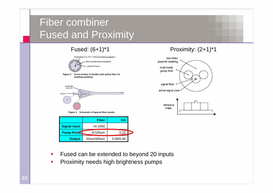
Fiber combinerFused and Proximity
Fused: (6+1)*1 Proximity: (2+1)*1
Fused can be extended to beyond 20 inputs
Proximity needs high brightness pumps
0.06/0.4620um/400umOutput
0.226*105umPump Ports
HI 1060Signal input
NAFiber
www.bookham.com
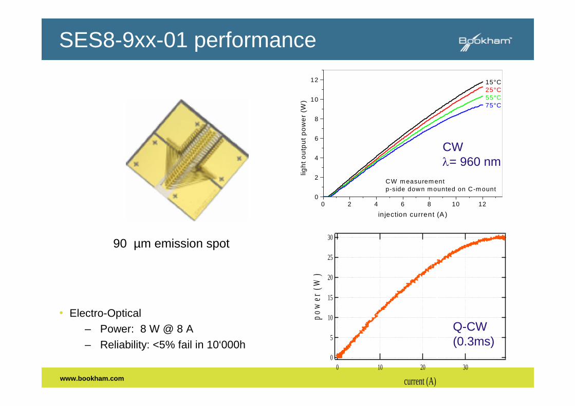
90 µm emission spot
0 2 4 6 8 10 120
2
4
6
8
10
12
CW m easurem entp-side down m ounted on C-m ount
lig
ht
ou
tpu
tp
ow
er
(W)
in jection current (A)
15°C25°C55°C75°C
SES8-9xx-01 performance
• Electro-Optical
– Power: 8 W @ 8 A
– Reliability: <5% fail in 10‘000h
CW= 960 nm
30
25
20
15
10
5
0
po
wer
(W)
3020100
current (A)
Q-CW(0.3ms)

www.bookham.com
0
1
2
3
4
5
6
7
8
9
10
11
12
ligh
to
utp
ut
po
we
r(a
.u.)
0 100 200 300 400 500 600 700 800 900 1100
time (h)
Broad Area 960nm (SES8-960-01)
• W=90um, P=13A (11W), Tj=130C
• Multi Cell Testing ongoing

www.bookham.com
MM Uncooled Module with >14W
• Record Performance:
– >14W @ 18A and 10°C Ths
– Standard MU package
• Module fully qualified
• MSA with EM4
0
2
4
6
8
10
12
14
16
0 2 4 6 8 10 12 14 16 18 20
injection current (A)
Ex
-Fib
reP
ow
er
(W)
10°C
25°C
45°C

© 2006 JDSU. All rights reserved.24
New generation 9xx broad area chip
19.0W maximum CW power from ~ 100um aperture
T=15C
0
5
10
15
20
25
30
0 5 10 15 20 25 30
Current, A
Po
wer,
W
pulsed
CW
0
2
4
6
8
10
12
14
16
0 5 10 15
Current, A
Po
we
r,W
25C
35C
45C
55C
70C
90C

© 2005 JDSU. All rights reserved.25
6396 Chip Reliability Improvement
MLE Results:
Revised reliability:– P=8.0W
– Th=35C
– Median time to failure=1,500,000 hrs (60% C.L.)
– 6% F at 20khr (60% C.L.)
hrs
n
eVE
op
A
6101.5
7.2
61.0
54.0
1%
5%
10%
50%
90%
99%
1000.00 1.00E+610000.00 1.00E+5Time, hrs
Unre
liabili
ty
6396 c
6390
6390
6396

26
Power Photonics: Beam Machining Tool
Many applications do not need diffraction limited beam: Direct Diode
200um,0.22
600um,0.22
1500um,0.22
50um.0.22
Direct Diode

27
Number of Lateral Modes in Fiber
With single mode lasers at 0.5W, all material processing needscan be met
‘Just’ challenge of coupling single mode laser diodes to fiber
1.E+02
1.E+03
1.E+04
1.E+05
1.E+06
0 200 400 600 800 1000 1200 1400 1600
Diameter (um)
Nu
mb
er
of
Mo
des
,
(bo
thP
ol)
,

www.bookham.com
Integrated Array of Single Mode Lasers
Single Mode Bar:
– 50 single mode lasers from 1 cm bar
– Power: 40W @ 50A
– Wavelength: 975nm0
10
20
30
40
50
0 10 20 30 40 50 60
Current (A)
Optic
alP
ow
er(W
)
0.0
0.5
1.0
1.5
2.0
2.5
Volta
ge
(V)
Product (by LIMO): Single mode laser bar coupled with lens array to 50umfiber:
25 W from 50um NA=0.22

29
Number of Lateral Modes in BA chip
Low NA broad area laser radiance: Closing in on single mode lasers 8W from NA=0.15NA: 400mW per lateral mode
Reduce NA of broad area laser to increase radiance NA dominated by thermal blooming ->Need chip with very high power conversion
100um BA, #of modes
0
5
10
15
20
25
30
35
40
0 0.1 0.2
NA
Nu
mb
er
of
mo
des
,

30
Low NA Broad Area Lasers:Thermal Blooming
Top view of BA laser
NAdn
n
dT
Issues of LowNAlasers
0
0.001
0.002
0.003
0.004
0.005
0.006
0.007
0.008
0 0.05 0.1 0.15 0.2 0.25
NA
dn
dT=10K
Low NA laser Achieved by low dn waveguide
dn Ridge
Parasitic through lateral temperature profile dT=10K -> dn=0.0025 -> NA=0.13
Leads to ,blooming’

31
Diode Power Conversion
Material limits: Even after optimized mirror losses (Sf , Rf , Rb ) and low threshold current. Due to limited mobility and carrier mass there are always trade-offs in
doping levels (series resistance Rs vs free carrier absorption) and
Bandgap discontinuities (leakage losses vs injection barriers)
Today’s approach: InGaAlAs material system
Asymmetric (thin p-region), low aluminum, low confinement LOC, low doping levels Holes have poor conductivity and high free carrier losses.
Relatively low barriers for high mobility and good injection (some thermal and vertical leakage)
PVIout
VI
P
)ln(2
)ln(
)ln(1
1
ff
bf
P
R
L
R
RS
seshFeFhfV RRV
IEE
eVhE
eV
111
I
I
I
I leakthI 1
Mobility:Series resistance
Density of States:Free carrier absorption
Bandgap discontinuities1. Thermal and vertical leakage2. Injection barriers

www.bookham.com
Bar with 425W CW at 980nm
– 425W at 980nm, 1cm, 50% FF
– On standard MCC
– 3.6mm long laser cavity
400
300
200
100
0
CW
pow
er(W
)
6005004003002001000
current (A)

33
Direct Coupled Diodes:
Practical limits to radiance?

© 2006 JDSU. All rights reserved.34
High-efficiency bars
>75% wall plug efficiency from 120W 940nm bar(SHEDS design)
Performance of JDSU/SHEDS 100W Bars
0
25
50
75
100
125
150
0 20 40 60 80 100 120
Drive Current (A)
Ou
tpu
tP
ow
er
(W)
50%
55%
60%
65%
70%
75%
80%
Po
we
rC
on
ve
rsio
nE
fficie
nc
y
35
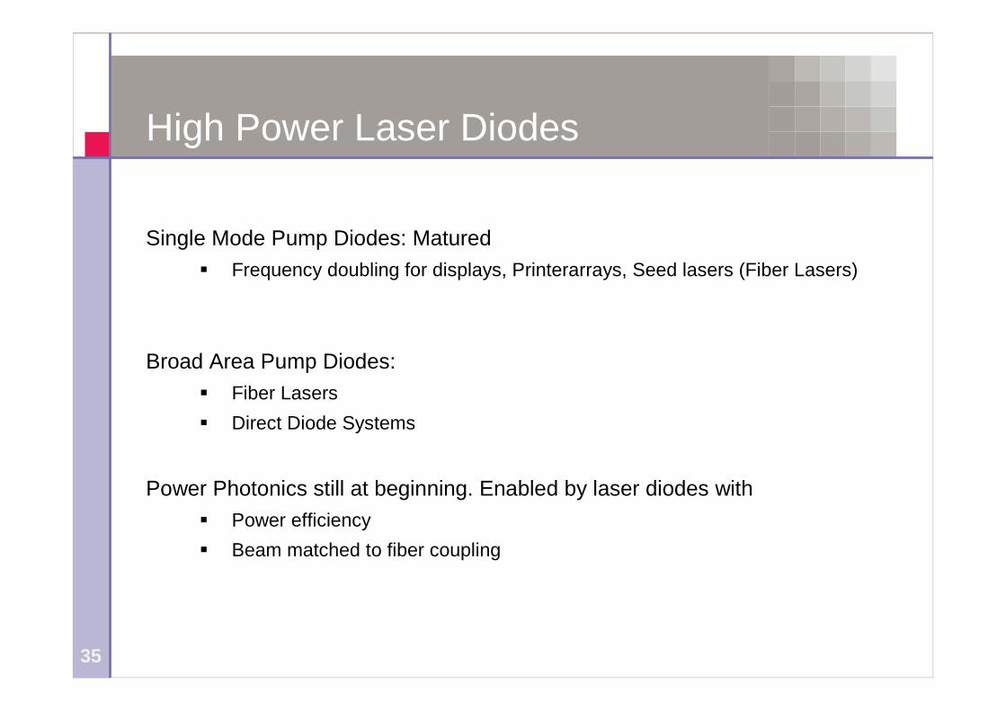
High Power Laser Diodes
Single Mode Pump Diodes: Matured
Frequency doubling for displays, Printerarrays, Seed lasers (Fiber Lasers)
Broad Area Pump Diodes:
Fiber Lasers
Direct Diode Systems
Power Photonics still at beginning. Enabled by laser diodes with
Power efficiency
Beam matched to fiber coupling


