High Performance V/F Control - 首页 汇川技术 · Ensure the protective earthing conductor...
74
User Guide MD290 AC Drive A01 Data Code: 19010376 V/F Control High Performance
Transcript of High Performance V/F Control - 首页 汇川技术 · Ensure the protective earthing conductor...

User Guide
MD290 AC Drive
A01
lnovance Technology
Address:No.16, Youxiang Road, Yuexi Town, Wuzhong District,
Suzhou 215104,P.R.China
Tel: +86-512-6637-6666
Fax:+86-512-6879-5286
www.inovance.cn
MD290 A
C Drive U
ser Guide
Data Code: 19010376
V/F Control
High Performance

Contents
Safety Information and Precautions 2
1 Product Information 4
11 Nameplate and Designation Rule 4
1.2 General Specifications 5
13 Environment 9
2 Wiring 10
21 Typical System Connection 10
22 Terminal Description 11
23 Remove the EMC and VDR Screws 14
3 Operation Panel (Keypad & Display) 16
31 Get Familiar with Operating Panel 16
4 Quick Setup 18
4.1 Setup flowchart 18
5 Parameter Table 25
51 Introduction 25
52 Standard Parameters 25
53 Monitoring Function Code 59
6 Troubleshooting 61
61 Performance Fine Tuning 61
62 AC Drive Fault Codes 62
63 AC Drive Common Symptoms and Diagnostics 69
Revision History71

Safety Information and Precautions
- 2 -
Safety Information and Precautions
This guide is packaged together with the MD290 AC drive It contains basic information for quick start of the drive For safety and more information, please refer to the MD290 AC Drive High Performance User Manual, which can be downloaded on the website http://wwwinovancecn
Electrical SafetyExtreme care must be taken at all times when working with the AC Drive or within the area of the AC Drive The voltages used in the AC Drive can cause severe electrical shock or burns and is potentially lethal. Only authorized and qualified personnel should be allowed to work on AC Drives
Machine/System Design and Safety of PersonnelMachine/system design, installation, commissioning startups and maintenance must be carried out by personnel who have the necessary training and experience They must read this safety information and the contents of this manual If incorrectly installed, the AC Drive may present a safety hazard
The AC Drive uses high voltages and currents (including DC), carries a high level of stored electrical energy in the DC bus capacitors even after power OFF These high voltages are potentially lethal
The AC Drive is NOT intended to be used for safety related applications/functions The electronic “STOP & START” control circuits within the AC Drive must not be relied upon for the safety of personnel Such control circuits do not isolate mains power voltages from the output of the AC Drive The mains power supply must be disconnected by an electrical safety isolation device before accessing the internal parts of the AC Drive
Safety risk assessments of the machine or process system which uses an AC Drive must be undertaken by the user and or by their systems integrator/designer In particular the safety assessment/design must take into consideration the consequences of the AC Drive failing or tripping out during normal operation and whether this leads to a safe stop position without damaging machine, adjacent equipment and machine operators/users This responsibility lies with the user or their machine/process system integrator
System integrator/designer must ensure the complete system is safe and designed according to the relevant safety standards Inovance Technology and Authorized Distributors can provide recommendations related to the AC drive to ensure long term safe operation
The installer of the AC Drive is responsible for complying with all relevant regulations for wiring, circuit fuse protection, earthing, accident prevention and electromagnetic (EMC regulations). In particular fault discrimination for preventing fire risk and solid earthing practices must be adhered to for electrical safety (also for good EMC performance) Within the European Union, all machinery in which this product is used must comply with required directives
Electrical Installation - SafetyElectrical shock risk is always present within an AC Drive including the output cable leading to the motor terminals Where dynamic brake resistors are fitted external to the AC Drive, care must be taken with regards to live contact with the brake resistors, terminals which are at high DC voltage and potentially lethal Cables from the AC Drive to the dynamic brake resistors should be double insulated as DC voltages are typically 600 to 700 VDC
Mains power supply isolation switch should be fitted to the AC Drive. The mains power supply must be disconnected via the isolation switch before any cover of the AC Drive can be removed or before any servicing work is undertaken stored charge in the DC bus capacitors of the PWM inverter is potentially lethal after the AC supply has been disconnected The AC supply must be isolated at least 10 minutes before any work can be undertaken as the stored charge will have been discharged through the internal bleed resistor fitted across the DC bus capacitors
Whenever possible, it is good practice to check DC bus voltage with a VDC meter before accessing the inverter bridge Where the AC Drive input is connected to the mains supply with a plug and socket, then upon disconnecting the plug and socket, be aware that the plug pins may be exposed and internally connected to DC bus capacitors (via the internal bridge rectifier in reversed bias). Wait 10 minutes to allow stored charge in the DC bus capacitors to be dissipated by the bleed resistors before commencing work on the AC Drive

Safety Information and Precautions
- 3 -
Electrical Shock HazardEnsure the protective earthing conductor complies with technical standards and local safety regulations Because the leakage current exceeds 35 mA in all models, IEC 61800-5-1 states that either the power supply must be automatically disconnected in case of discontinuity of the protective earthing conductor or a protective earthing conductor with a cross-section of at least 10 mm2 (Cu) or 16 mm2 (Al) must be used Failure to comply may result in death or serious injury
When using an earth leakage circuit breaker, use a residual current operated protective device (RCD) of type B (breaker which can detect both AC and DC) Leakage current can cause unprotected components to operate incorrectly If this is a problem, lower the carrier frequency, replace the components in question with parts protected against harmonic current, or increase the sensitivity amperage of the leakage breaker to at least 200 mA per drive
Factors in determining leakage current:
• Size of the AC drive
• AC drive carrier frequency
• Motor cable type and length
• EMI/RFI filter
Approvals
CE mark indicates compliance with European safety and environmental regulations It is required for engaging in business and commerce in Europe
European standards include the Machinery Directive for machine manufacturers, the Low Voltage Directive for electronics manufacturers, and EMC guidelines for controlling noise
The drive with CE mark meets the following EMC guidelines and the Low Voltage Directive
• 2014/35/EU: Low Voltage Directive • 2014/30/EU: Electromagnetic compatibility
Machines and devices used in combination with this drive must also be CE certified and marked. The integrator who integrates the drive with the CE mark in into other devices has the responsibility of ensuring compliance with CE standards and verifying that conditions meet European standards
Motor Thermal ProtectionMotor thermal protection is not assessed by UL

1 Product Information
- 4 -
1 Product Information
11 Nameplate and Designation Rule
MODEL: MD290T18.5G/22P-INTINPUT: 3PH AC 380-480V 59.0A 50Hz/60Hz OUTPUT: 3PH AC 0-480V 45.0A 0-500Hz 22kW
Suzhou Inovance Technology Co.,Ltd.
S/N: Serial Number
AC drive modelRated input
Rated outputS/N code
Nameplate
Manufacturer
MD290 series AC drive
MD290 T
Voltage Class
T
General type
Mark
G
Mark
Type of Applicable Motor
Three-phase 380 to 480 V
With Built-in Braking Unit
With Output Reactor and Cabinet
NoNull
Mark
E467465IND.CONT.EQ.
-L
Version
Variant 1Null
Mark
Variant 2-INT
185
Mark
185
Applicable Motor (kW)
160160
18.5 22 PG
Yes
-INT
450450
NoB
Null Yes
Mark
Fan, pump
Mark
P
Type of Applicable Motor
185
Mark
22
Applicable Motor (kW)
160200
450500
/

1 Product Information
- 5 -
1.2 General SpecificationsTable 1-1 Ratings of MD290T185G/22P to MD290T160G/200P
Voltage Class 380 to 480 VAC
MD290TxxG/xxP(B【1】)(-INT) 185G/22P 22G/30P 30G/37P 37G/45P 45G/55P 55G/75P 75G/90P
Driv
e In
put
Rated Input Voltage Three-phase 380 to 480 V, -15% to +10%
Rated Input Current, [A]
G type 495 59 57 69 89 106 139
P type 59 658 71 86 111 143 167
Rated Input Frequency 50/60 Hz, ±5% (475 to 63 Hz)
Power Capacity, [kVA] G type 45 54 52 63 81 97 127
P type 54 60 65 79 102 131 153
D
rive
Out
put
Applicable Motor G type [kW] 185 22 30 37 45 55 75
G type [HP] 25 30 40 50 60 75 100
P type [kW] 22 30 37 45 55 75 90
P type [HP] 30 40 50 60 75 100 120
Output Current, [A] G type 37 45 60 75 91 112 150
P type 45 60 75 91 112 150 176
Default Carrier Frequency, [kHz] 6 6 6 5 5 4 3
Overload Capacity G type: 150% for 60 SecP type: 110% for 60 Sec
Max Output Voltage Three-phase 380 to 480 VAC (proportional to input voltage)
Max Output Frequency 500 Hz
Bra
king
R
esis
tor
Recommended Power, [kW] 4 45 6 7 9 11 15
Recommended Resistance, Min. [Ω] 24 24 192 148 128 96 68
Ther
mal
D
esig
n Thermal design power, [kW] 0478 0551 0694 0815 101 121 157
Air flow, [CFM] 519 574 1185 1185 1222 1222 2186
Enclosure IP20
Note 【1】: "B" denotes build-in brake function for MD290T185G/22P to MD290T75G/90P

1 Product Information
- 6 -
Table 1-2 Ratings of MD290T90G/110P to MD290T160G/200P
Voltage Class 380 to 480 VAC
MD290TxxG/xxP(-INT) 90G/110P 110G/132P 132G/160P 160G/200P
Driv
e In
put
Rated Input Voltage Three-phase 380 to 480 V, -15% to +10%
Rated Input Current, [A]
G type 164 196 240 287
P type 198 239 295 359
Rated Input Frequency 50/60 Hz, ±5%
Power Capacity, [kVA]
G type 150 179 220 263
P type 181 219 270 328
D
rive
Out
put
Applicable Motor G type [kW] 90 110 132 160
G type [HP] 120 150 180 220
P type [kW] 110 132 160 200
P type [HP] 150 180 220 267
Output Current, [A]
G type 176 210 253 304
P type 210 253 304 377
Default Carrier Frequency, [kHz] 3 3 3 3
Overload Capacity G type: 150% for 60 SecP type: 110% for 60 Sec
Max Output Voltage Three-phase 380 to 480 VAC (proportional to input voltage)
Max Output Frequency 500 Hz
Bra
king
R
esis
tor Recommended Power, [kW] 18 22 26 32
Recommended Resistance, Min. [Ω] 53 53 35 35
Ther
mal
D
esig
n Thermal design power, [kW] 181 214 285 356
Air flow, [CFM] 2872 3422 547 627
Enclosure IP20
Figure 1-1 Overall dimensions of MD500T185GB to MD500T37GB (plastic housing)
AW
B H
D
d x 4
Figure 1-2 Overall dimensions of MD500T45GB to MD500T160G (sheet metal housing)
DW
A
H
B H1
d x 4

1 Product Information
- 7 -
Table 1-3 Ratings of MD290T200G to MD290T280G and MD290T220P to MD290T315P
Voltage Class 380 to 480 VAC
Model: MD290Txxxx(-L)**(-INT) 200G 220P 220G 250P 250G 280P 280G 315P
Driv
e In
put Rated Input Voltage Three-phase 380 to 480V, -15% to +10%
Rated Input Current [A] 365 410 410 456 441 507 495 559
Power Capacity, [kVA] 334 375 375 417 404 464 453 511
Rated input frequency 50/60 Hz, ±5%
Driv
e O
utpu
t
Applicable Motor, [kW] 200 220 220 250 250 280 280 315
Output Current, [A] 377 426 426 465 465 520 520 585
Default carrier frequency, [kHz] 3 3 3 3 3 3 3 3
Overload Capacity G type: 150% for 60 SecP type: 110% for 60 Sec
Max output voltage Three-phase 380 to 480 VAC (proportional to input voltage)
Max output frequency 500 Hz
Bra
king
R
esis
tor Recommended Power, [kW] 38 38 42 42 48 48 54 54
Recommended Resistance, min [Ω]
29 29 27 27 23 23 21 21
Ther
mal
D
esig
n Thermal design power, [kW] 415 455 506 533 569 631 691 754
Air flow, [CFM] 6384 7225 7894 882 645 860 860 860
Enclosure IP00
Table 1-4 Ratings of MD290T315G to MD290T450G and MD290T355P to MD290T500P
Voltage Class 380 to 480 VAC
Model: MD290Txxxx(-L)**(-INT) 315G 355P 355G 400P 400G 450P 450G 500P
Driv
e In
put Rated Input Voltage Three-phase 380 to 480V, -15% to +10%
Rated Input Current [A] 565 624 617 708 687 782 782 840
Power Capacity, [kVA] 517 571 565 647 629 715 716 768
Rated input frequency 50/60 Hz, ±5%
Driv
e O
utpu
t
Applicable Motor, [kW] 315 355 355 400 400 450 450 500
Output Current, [A] 585 650 650 725 725 820 820 880
Default carrier frequency, [kHz] 3 3 3 3 3 3 3 3
Overload Capacity G type: 150% for 60 Sec (For MD290T450G, the capacity is 130%)P type: 110% for 60 Sec
Max output voltage Three-phase 380 to 480 VAC (proportional to input voltage)
Max output frequency 500 Hz
Bra
king
R
esis
tor Recommended Power, [kW] 54 60 69 69 78 78 87 87
Recommended Resistance, min [Ω]
21 19 17 17 15 15 13 13
Ther
mal
D
esig
n Thermal design power, [kW] 415 455 506 533 569 631 691 754
Air flow, [CFM] 6384 7225 7894 882 645 860 860 860
Enclosure IP00
Note **: Model name with "L" in Table 1-3 and Table 1-4 means with the built-in AC output reactor and cabinet

1 Product Information
- 8 -
Figure 1-3 Overall dimensions of MD290T200G to MD290T450G and MD290T220P to MD290T500P
W A1
A2
D
W1
H1 H
D1
62
A1
B1
B2
Figure 1-4 Overall dimensions of MD290T200G-L to MD290T450G-L and MD290T220P-L to MD290T500P-L (with output AC reactor)
D1
62
B1
B
D A
A1
W
W1
H1 H

1 Product Information
- 9 -
13 Environment
Item Requirements
Altitude Below 1000 m 1% current derating current per 100 m at 1000 m to 3000 mMax 3000 m allowedFor altitudes above 3000 m, contact Inovance regarding PELV
Storage Temperature -25°C to +70°C
Operating Temperature -10°C to +40°C15% current derating per 1°C at 40°C to 50°CMax 50°C allowed
Max Humidity ≤95%RH, no-condensing
Vibration ≤0.6g
Running Environment PD2
Power Supply System TT/TN
IT (Remove the screws of VDR and EMC filter according to.2.4.)
Pollution level PD2
Overvoltage category OVC III
Enclosure IP20 for 160kW and below, and IP00 for 200kW and large

2 Wiring
- 10 -
2 Wiring
21 Typical System Connection
R
S
U
V
W
+24Vdc
DI1
DI2
DI3
DI4
DI5
COM
+10V
AI2
GND
485+
485-
GND
AI1
T/C
T/B
T/A
FM
COM
DO1
CME
AO1
GND
L1
L2
L3
- + BR
- + BR
Jumper J9 for AI2
Forward run F4-00 = 1
Forward jog F4-01 = 4
Fault reset F4-02 = 9
Reference 1 F4-03 = 12
Reference 2 F4-04 = 13
The DI5 supports a maximum of 100 kHz pulse input.
VR 1 to 5 kΩ
0 to 10 V
0 to 10 VDC or 0 to 20 mA
MD38TX1(option)
J13 extension port
Analog output (voltage/current switchable)0 to 10VDC/ 0 to 20mA
Pulse output: 0 to 100 kHz Open-collector output:10 to 24VDC/ 0 to 50mA
Open-collector output:10 to 24VDC/ 0 to 50mA
Relay output: 250 VAC, between 10 mA and 3 A30 VDC, between 10 mA and 1 A
Braking unit
Mains External RFI filter
Line reactor (option)
Supply ground
RS485+
RS485 -
Current mode
Voltage mode
Current mode
Voltage mode
Jumper J7 for AO1
0 100%
RJ45 Hot pluggable Remote Keypad
Output reactor (option)
IM
The drive of 18.5 to 75kW with GB or 22 to 90kW with ‘PB’
has built-in braking unit.
The drive of 90G/110P or larger power requires an optional external dynamic braking unit.
A braking resistor with temperature switch

2 Wiring
- 11 -
22 Terminal Description Terminals of Main Circuit
Figure 2-1 Main circuit terminals of MD290T185G/22P to MD290T37G/45P (plastic housing)
Warning: Do not use terminal (-) for braking resistor, otherwise, AC drive would be damaged
:
Figure 2-2 Main circuit terminals of MD290T45G/55P to MD290T160G/200P (sheet metal housing)
R SPOWER
T BR (+) (-) VU WMOTOR
Figure 2-3 Main circuit terminals of MD290T200G to MD290T450G and MD290T220P to MD290T500P
U
V
W
Terminal Terminal Name Description
R, S, T Three-phase supply input Connect to the three-phase AC power supply
(-), (+) DC bus terminalsConnected to external braking unit (MDBUN) with AC drive units of 90 kW and above
BR, (+) Braking resistor connectionConnected to external braking resistor for AC drive units of 75 kW and below
U, V, W Output terminals Connect to a three-phase motor
Ground (PE) Grounding connection
2 Wiring
- 12 -
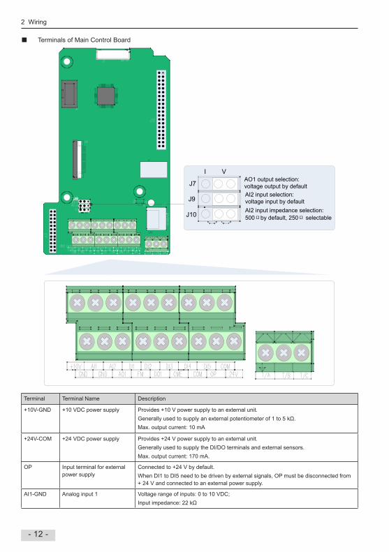
Terminals of Main Control Board
AO1 output selection: voltage output by defaultJ7
J9
J10
I V
AI2 input impedance selection: 500Ωby default, 250Ω selectable
AI2 input selection: voltage input by default
Terminal Terminal Name Description
+10V-GND +10 VDC power supply Provides +10 V power supply to an external unit Generally used to supply an external potentiometer of 1 to 5 kΩ. Max output current: 10 mA
+24V-COM +24 VDC power supply Provides +24 V power supply to an external unitGenerally used to supply the DI/DO terminals and external sensors Max output current: 170 mA
OP Input terminal for external power supply
Connected to +24 V by defaultWhen DI1 to DI5 need to be driven by external signals, OP must be disconnected from + 24 V and connected to an external power supply
AI1-GND Analog input 1 Voltage range of inputs: 0 to 10 VDC;Input impedance: 22 kΩ
2 Wiring
- 13 -
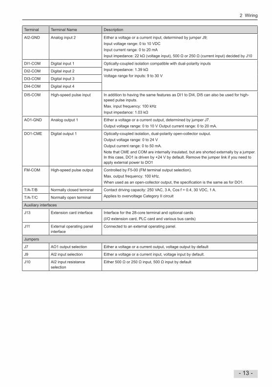
Terminal Terminal Name Description
AI2-GND Analog input 2 Either a voltage or a current input, determined by jumper J9;Input voltage range: 0 to 10 VDCInput current range: 0 to 20 mAInput impedance: 22 kΩ (voltage input), 500 Ω or 250 Ω (current input) decided by J10
DI1-COM Digital input 1 Optically-coupled isolation compatible with dual-polarity inputsInput impedance: 1.39 kΩVoltage range for inputs: 9 to 30 V
DI2-COM Digital input 2
DI3-COM Digital input 3
DI4-COM Digital input 4
DI5-COM High-speed pulse input In addition to having the same features as DI1 to DI4, DI5 can also be used for high- speed pulse inputsMax input frequency: 100 kHz Input impedance: 1.03 kΩ
AO1-GND Analog output 1 Either a voltage or a current output, determined by jumper J7Output voltage range: 0 to 10 V Output current range: 0 to 20 mA
DO1-CME Digital output 1 Optically-coupled isolation, dual-polarity open-collector outputOutput voltage range: 0 to 24 V Output current range: 0 to 50 mANote that CME and COM are internally insulated, but are shorted externally by a jumper In this case, DO1 is driven by +24 V by default Remove the jumper link if you need to apply external power to DO1
FM-COM High-speed pulse output Controlled by F5-00 (FM terminal output selection)Max output frequency: 100 kHzWhen used as an open-collector output, the specification is the same as for DO1.
T/A-T/B Normally closed terminal Contact driving capacity: 250 VAC, 3 A, Cos f = 04, 30 VDC, 1 AApplies to overvoltage Category II circuitT/A-T/C Normally open terminal
Auxiliary interfaces
J13 Extension card interface Interface for the 28-core terminal and optional cards(I/O extension card, PLC card and various bus cards)
J11 External operating panel interface
Connected to an external operating panel
Jumpers
J7 AO1 output selection Either a voltage or a current output, voltage output by default
J9 AI2 input selection Either a voltage or a current input, voltage input by default
J10 AI2 input resistance selection
Either 500 Ω or 250 Ω input, 500 Ω input by default
2 Wiring
- 14 -
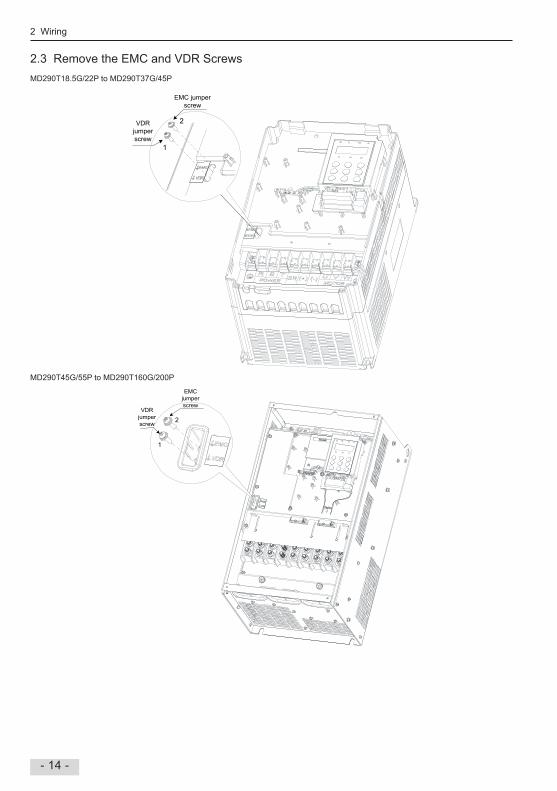
23 Remove the EMC and VDR ScrewsMD290T185G/22P to MD290T37G/45P
VDR jumper screw
EMC jumper screw
1
2
MD290T45G/55P to MD290T160G/200P
VDR jumper screw
EMC jumper screw
1
2

2 Wiring
- 15 -
MD290T200G to MD290T450G and MD290T220P to MD290T500P
VDR jumper screw 1
2
EMC jumper screw

3 Operating Panel (Keypad & Display)
- 16 -
3 Operation Panel (Keypad & Display)
31 Get Familiar with Operating Panel Overview
MF.KRUN STOPRES
QUICK
PRG ENTER
RUN LOCAL/ REMOT FWD/REV TUNE/TC
RPM %A VHz
Other status indicator
Running direction indicator
Parameter unit indicator
Increment key
Confirm key
Shift key
Decrement key
Stop/Reset key
Multi-function selection key
Command source indicator
Running status indicator
LED display for parameters
Program key
Menu mode selection key
Run key
Status IndicatorsThere are four red LED status indicators at the top of the operating panel
Indicator Indication
RUNOFF indicates the STOP status
ON indicates the RUNNING status
LOCAL/REMOTOFF indicates under operating panel control
ON indicates under terminal control
FLASHING indicates under serial communication control
FWD/REVOFF indicates reverse motor rotation
ON indicates forward motor rotation
TUNE/TCON indicates torque control mode
FLASHING SLOWLY (once a second) indicates auto-tuning status
FLASHING QUICKLY (four times a second) indicates a fault condition
Parameter Unit Indicator
Indicator appearance Meaning
RPM %A VHz Hz for frequency
RPM %A VHz A for current
RPM %A VHz V for voltage
RPM %A VHz RPM for motor speed
RPM %A VHz Percentage

3 Operating Panel (Keypad & Display)
- 17 -
Keys on Operation Panel
Key Key Name Function
PRGProgramming Enter or exit Level I menu
Return to the previous menu
ENTERConfirm Enter each level of menu interface
Confirm displayed parameter setting.
Increment When navigating a menu, it moves the selection up through the screens available
When editing a parameter value, it increases the displayed valueWhen the AC drive is in RUN mode, it increases the speed
Decrement When navigating a menu, it moves the selection down through the screens available
When editing a parameter value, it decreases the displayed valueWhen the AC drive is in RUNNING mode, it decreases the speed
Shift Select the displayed parameter in the STOP or RUNNING status
Select the digit to be modified when modifying a parameter value
RUNRUN Start the AC drive when using the operating panel control mode
It is inactive when using the terminal or communication control mode
STOPRES
Stop/Reset Stop the AC drive when the drive is in the RUNNING statusPerform a reset operation when the drive is in the FAULT status Note: The functions of this key can be restricted by using function F7-02
MF.KMultifunction Perform a function switchover as defined by the setting of F7-01, for example to quickly switch
command source or direction
QUICKMenu mode selection Press it to switch over between menu modes as defined by the setting of FP-03.
Operations of Parameters
5000 F0 F0
F1
FP
A0
A1
U0
AC
FP
A0
A1
F0
F1
F0 00
F0 01
F0 28
F0 00
F0 28
1
2
0
F0 02
ENTERPRG
PRG PRG PRG PRG
ENTER ENTERENTER
PRG
Parameter arrangement
Function Code Group Description Remark
F0 to FF Standard function code group Standard function parameters
A0 to AC Advanced function code group AI/AO correction
U0 to U3 RUNNING status function code group Display of basic parameters

4 Quick Setup
- 18 -
4 Quick Setup
4.1 Setup flowchart
START Para Parameter name Default Commission
Before power on
Install and wire the drive Install and wire the drive as explained in chapters 1 to 3 of the MD290 AC Drive Advanced User Guide
Check wirings -
of power supply and AC drive outputs
Restore parameters FP-01 Parameter initialization 0
0: No operation1: Restore default settings except motor parameters2: Clear records including errors 4: Back up parameters501: Restore user’s backup parametersNOTE: It is recommended to "Restore default settings" prior to commissioning the AC drive
Set motor parameters Motor Nameplate
F1-01 Rated motor power model dependent 15
Unit: kW
F1-02 Rated motor voltage model dependent 380
Unit: V
F1-03 Rated motor current model dependent 34
Unit: A
F1-04 Rated motor frequency model dependent 50
Unit: Hz
F1-05 Rated motor speed model dependent 2800
Unit: rpm
CONTINUE Para Parameter name Default Commission

4 Quick Setup
- 19 -
CONTINUE Para Parameter name Default Commission
Perform motor auto tuning F1-37 Auto-tuning selection 0
If AI2 is frequency reference
0: No auto-tuning1: Static auto-tuning 12: Dynamic auto-tuning3: Static auto-tuning 2NOTE: Motor won’t rotate at this stageSteps of auto-tuning:1 Make sure the UVW connection between inverter and motor is not cut off by output contactor; if it is cut off, then manually handle with the output contactor
3 Set F1-37 = 3, press ENTER , then LED on panel will display letters "TUNE"
4 Press the RUN key on panel, then motor starts auto-tuning, it usually takes about
30 seconds to finish this auto-tuning, wait until LED stops displaying "TUNE".5 Restore F0-02 to the default value 1
Set AI2 F4-18 AI curve 2 minimum input 000
If AI3 is frequency reference
0 V to F4-20;
F4-19 Corresponding percentage of AI2 minimum input
00
-1000% to 1000%
F4-20 AI2 maximum input 1000
F4-18 to 1000 V
F4-21 Corresponding percentage of AI2 maximum input
1000
-1000% to 1000%
Set AI3 F4-23 AI curve 3 minimum input 000
If multi-reference is frequency reference
0 V to F4-25;
F4-24 Corresponding percentage of AI3 minimum input
00
-1000% to 1000%
F4-25 AI3 maximum input 1000
F4-23 to 1000 V
F4-26 Corresponding percentage of AI3 maximum input
1000
-1000% to 1000%
Set multi-reference FC-00 Reference 0 00
00 to 1000%
FC-01 to FC-15
Reference 1-15 00
00 to 1000%
CONTINUE Para Parameter name Default Commission

4 Quick Setup
- 20 -
CONTINUE Para Parameter name Default Commission
If any digital input is used
Set DI function F4-00 DI1 function selection 1
0: No function1: Forward RUN (FWD)2: Reverse RUN (REV)3: Three-wire control4: Forward JOG (FJOG)5: Reverse JOG (RJOG)6: Terminal UP7: Terminal DOWN8: Coast to stop9: Fault reset (RESET)10: RUN pause11: External fault normally open (NO) input12: Multi-reference terminal 113: Multi-reference terminal 214: Multi-reference terminal 315: Multi-reference terminal 416: Terminal 1 for acceleration/deceleration time selection17: Terminal 2 for acceleration/deceleration time selection18: Frequency source switchover19: UP and DOWN setting clear (terminal, keypad)20: Command source switchover terminal 121: Acceleration/Deceleration prohibited22: PID pause23: PLC status reset24: Swing pause25: Counter input26: Counter reset27: Length count input28: Length reset29: Torque control prohibited30: Pulse input (enabled only for DI5)31: Reserved32: Immediate DC injection braking33: External fault normally closed (NC) input34: Frequency modification forbidden35: PID action direction reverse 36: External STOP terminal 137: Command source switchover terminal 238: PID integral disabled39: Switchover between main frequency source X and preset frequency40: Switchover between auxiliary frequency source Y and preset frequency41: Motor selection terminal 142: Motor selection terminal 243: PID parameter switchover
CONTINUE Para Parameter name Default Commission

4 Quick Setup
- 21 -
CONTINUE Para Parameter name Default Commission
F4-00 DI1 function selection 1
44: User-defined fault 145: User-defined fault 246: Speed control/Torque control switchover47: Emergency stop48: External STOP terminal 249: Deceleration DC injection braking50: Clear the current running time51–59: ReservedSetting range:0 to 59;
F4-01 DI2 function selection 4
Setting range same as DI1
F4-02 DI3 function selection 9
Setting range same as DI1
F4-03 DI4 function selection 12
Setting range same as DI1
F4-04 DI5 function selection 13
Setting range same as DI1;
F4-05 DI6 function selection 0
Setting range same as DI1;
F4-06 DI7 function selection 0
Setting range same as DI1;
F4-07 DI8 function selection 0
Setting range same as DI1
F4-08 DI9 function selection 0
Setting range same as DI1
F4-09 DI10 function selection 0
If any digital output is used Setting range same as DI1;
Set DO function F5-00 FM output mode selection 0
0: FM terminal outputs pulses, the frequency of which represents the value of variable which is assigned by F5-061: FM terminal outputs switch signal, the value of which represents the status of variable which is assigned by F5-01
F5-01 FM (switch signal) function selection 0
0: No output1: AC Drive running2: Fault output 3: Frequency-level detection FDT1 output4: Frequency reached5: Zero-speed running (no output at stop)6: Motor overload pre-warning7: AC drive overload pre-warning
CONTINUE Para Parameter name Default Commission

4 Quick Setup
- 22 -
CONTINUE Para Parameter name Default Commission
Set DO function F5-01 FM (switch signal) function selection 0
8: Set count value reached9: Designated count value reached10: Length reached11: PLC cycle completed12: Accumulative running time reached13: Frequency limited14: Torque limited15: Ready for RUN16: Reserved17: Frequency upper limit reached18: Frequency lower limit reached (no output at stop)19: Undervoltage status output20: Communication setting21,22: Reserved23: Zero-speed running 2 (having output at stop)24: Accumulative power-on time reached25: Frequency level detection FDT2 output26: Frequency 1 reached27: Frequency 2 reached28: Current 1 reached29: Current 2 reached30: Timing duration reached31: AI1 input limit exceeded32: Load lost33: Reverse running34: Zero current status35: IGBT temperature reached36:Software current limit exceeded37: Frequency lower limit reached (having output at stop)38: Alarm output39: Motor overheat warning40: Current running time reached41: Fault output (no output at undervoltage)
F5-02 Relay function selection(T/A-T/B-T/C) 2
Setting range same as FM;
F5-03 Relay function selection (P/A-P/B-P/C) 0
Setting range same as FM; the relay P/A-P/B-P/C is on extension I/O card
F5-04 DO1 function selection 1
Setting range same as FM
F5-05 Extension card DO2 function selection 4
Setting range same as FM
CONTINUE Para Parameter name Default Commission

4 Quick Setup
- 23 -
CONTINUE Para Parameter name Default Commission
if an analog output is used
F5-06 FM (pulse signal) function selection 0
0: Running frequency1: Set frequency2: Output current3: Reserved4: Output power5: Output voltage6: Pulse input7: AI18: AI29: AI310: Length11: Count value12: Communication setting13: Motor rotational speed14: Output current15: Output voltage16: Reserved
Set AO function F5-07 AO1 function selection 0
Setting range same as F5-06
F5-08 AO2 function selection 1
Setting range same as F5-06; AO2 is on extension card
Set accel/decel time F0-17 Acceleration time 1 model dependent
If smooth accel/decel is requested
000 to 65000s (if F0-19=2)00 to 65000s (if F0-19=1)0 to 65000s (if F0-19=0)
F0-18 Deceleration time 1 model dependent
000 to 65000s (if F0-19=2)00 to 65000s (if F0-19=1)0 to 65000s (if F0-19=0)
Set S-curve F6-07 Acceleration/Deceleration mode 0
0 : Linear acceleration/deceleration1: Static S-curve acceleration/deceleration2: Dynamic S-curve acceleration/deceleration
F6-08 Time proportion of S-curve at Accel start 300
00% to (1000% - F6-09)
F6-09 Time proportion of S-curve at Accel end 300
00% to (1000% - F6-08)
CONTINUE Para Parameter name Default Commission

4 Quick Setup
- 24 -
CONTINUE Para Parameter name Default Commission
Set VF parameters F3-00 V/F curve selection 0
0: Linear V/F1: Multi-point V/F2: Square V/F3: 12-power V/F4: 14-power V/F6: 16-power V/F8: 18-power V/F9: Reserved10: V/F complete separation11: V/F half separationSETTING RANGE: 0 to 11
F3-01 Torque boost 00
00 to 300 %; NOTE: if it is 0, then fixed torque boost is activated, and it is recommended to use fixed torque boost.
F3-02 Frequency limit of torque boost 5000
000 Hz to maximum output frequency
F3-03 Multi-point V/F frequency 1 000
000 Hz to F3-05
F3-04 Multi-point V/F voltage 1 00
00 to 1000 V
F3-05 Multi-point V/F frequency 2 000
F3-03 to F3-07, Hz
F3-06 Multi-point V/F voltage 2 00
00 to 1000 V
F3-07 Multi-point V/F frequency 3 000
F3-05 to rated motor frequency F1-04, Hz
F3-08 Multi-point V/F voltage 3 00
00 to 1000 V
Trial RUN Use operating panel, or digital input terminal, or serial communication control, to start inverter, check if the running performance satisfies your application. If yes, then go forward to next step, if NO, then go back to check
Finish

5 Parameter Table
- 25 -
5 Parameter Table
51 Introduction Groups F and A include standard function parameters Group U includes the monitoring function parameters and extension card communication parameters
The parameter description tables in this chapter use the following symbols The symbols in the parameter table are described as follows:
Symbol Meaning
It is possible to modify the parameter with the drive in the stop or in the Run status
It is not possible to modify the parameter with the drive in the Run status
The parameter is the actual measured value and cannot be modified.
* The parameter is a factory parameter and can be set only by the manufacturer
52 Standard Parameters
Para No Para Name Setting Range Default Property
Group F0: Standard Parameters
F0-00 G/P type display 1 : G type2: P type
Model dependent
F0-01 Motor 1 control mode 2: V/F control 2
F0-02 Command source selection 0: Operating panel (keypad & display) (LED off)1: Terminal I/O control (LED on)2: Serial comms. (LED flashing)
0
F0-03 Main frequency reference setting channel selection
0: Digital setting (non-retentive at power down)1: Digital setting (retentive at power down)2: AI13: AI24: AI35: Pulse reference6: Multi-reference7: Simple PLC8: PID reference9: Serial comms
0
F0-04 Auxiliary frequency reference setting channel selection
0: Digital setting (non-retentive at power down)1: Digital setting (retentive at power down)2: AI13: AI24: AI35: Pulse reference6: Multi-reference7: Simple PLC8: PID reference9: Serial comms
0
F0-05 Base value of range of auxiliary frequency reference for Main and auxiliary calculation
0: Relative to maximum frequency1: Relative to main frequency reference
0
F0-06 Range of auxiliary frequency reference for main and auxiliary calculation
0% to 150% 100%

5 Parameter Table
- 26 -
Para No Para Name Setting Range Default Property
F0-07 Final Frequency reference setting selection 00 to 34
Main and auxiliary calculation relationship0: Main + auxiliary1: Main - auxiliary2: Max (main, auxiliary)3: Min (main, auxiliary)
Final frequency reference selection 0: Main frequency reference1: Main and auxiliary calculation result2: Switchover between main frequency reference and auxiliary frequency reference3: Switchover between main frequency reference and main and auxiliary calculation result 4: Switchover between auxiliary frequency reference and main and auxiliary calculation result
00
F0-08 Preset frequency 000 to max frequency (F0-10) 5000 Hz
F0-09 Running direction 0: Run in the default direction 1: Run in the direction reverse to the default direction
0
F0-10 Max frequency 5000 to 50000 Hz 5000 Hz
F0-11 Setting channel of frequency upper limit 0: Set by F0-121: AI12: AI23: AI34: Pulse reference (DI5)5: Communication reference
0
F0-12 Frequency reference upper limit Frequency lower limit (F0-14) to max frequency (F0-10)
5000 Hz
F0-13 Frequency reference upper limit offset 000 Hz to max frequency (F0-10) 000 Hz
F0-14 Frequency reference lower limit 000 Hz to frequency upper limit (F0-12) 000 Hz
F0-15 Carrier frequency Model dependent Model dependent
F0-16 Carrier frequency adjusted with temperature 0: Disabled1: Enabled
1
F0-17 Acceleration time 1 000s to 65000s (F0-19 = 2)00s to 65000s (F0-19 = 1)0s to 65000s (F0-19 = 0)
Model dependent
F0-18 Deceleration time 1 000s to 65000s (F0-19 = 2)00s to 65000s (F0-19 = 1)0s to 65000s (F0-19 = 0)
Model dependent
F0-19 Acceleration/Deceleration time unit 0: 1s1: 01s2: 001s
1

5 Parameter Table
- 27 -
Para No Para Name Setting Range Default Property
F0-21 Frequency offset of Auxiliary frequency setting channel for main and auxiliary calculation
000 Hz to max frequency (F0-10) 000 Hz
F0-22 Frequency reference resolution 2: 001 Hz 2
F0-23 Retentive of digital setting frequency upon stop
0: Not retentive1: Retentive
0
F0-24 Motor parameter group selection 0: Motor parameter group 11: Motor parameter group 2
0
F0-25 Acceleration/Deceleration time base frequency
0: Maximum frequency (F0-10)1: Frequency reference2: 100 Hz
0
F0-26 Base frequency for UP/DOWN modification during running
0: Running frequency1: Frequency Reference
0
F0-27 Command source + frequency source 000 to 999
Terminal control + frequency sourceThe same as that of units position
Operating panel + frequency source0: Not binding1: Digital setting2: AI13: AI24: AI35: Pulse reference (DI5)6: Multi-reference7: Simple PLC8: PID reference9: Serial comms
Serial comms + frequency sourceThe same as that of units position
000
F0-28 Serial port comms protocol 0: Modbus protocol1: PROFIBUS-DP protocol or CANopen protocol
0
Group F1: Motor 1 Parameters
F1-00 Motor type selection 0: Common asynchronous motor1: Variable frequency asynchronous motor
0
F1-01 Rated motor power 01 to 10000 kW Model dependent
F1-02 Rated motor voltage 1 to 2000 V Model dependent
F1-03 Rated motor current 0.01 to 655.35 A (AC drive power ≤ 55 kW)01 to 65535 A (AC drive power > 55 kW)
Model dependent
F1-04 Rated motor frequency 001 Hz to max frequency Model dependent
F1-05 Rated motor speed 1 to 65535 rpm Model dependent
F1-06 Stator resistance 0.001 to 65.535 Ω (AC drive power ≤ 55 kW)0.0001 to 6.5535 Ω (AC drive power > 55 kW)
Auto-tuning dependent

5 Parameter Table
- 28 -
Para No Para Name Setting Range Default Property
F1-07 Rotor resistance 0.001 to 65.535 Ω (AC drive power ≤ 55 kW)0.0001 to 6.5535 Ω (AC drive power > 55 kW)
Auto-tuning dependent
F1-08 Leakage inductive reactance 0.01 to 655.35 mH (AC drive power ≤ 55 kW)0001 to 65535 mH (AC drive power > 55 kW)
Auto-tuning dependent
F1-09 Mutual inductive reactance 0.1 to 6553.5 mH (AC drive power ≤ 55 kW)001 to 65535 mH (AC drive power > 55 kW)
Auto-tuning dependent
F1-10 No-load current 0.01 A to F1-03 (AC drive power ≤ 55 kW)01 A to F1-03 (AC drive power > 55 kW)
Auto-tuning dependent
F1-37 Motor auto-tuning method selection 0: No auto-tuning1: Static auto-tuning 12: Dynamic auto-tuning3: Static auto-tuning 2
0
Group F3: V/F Control Parameters
F3-00 V/F curve setting 0 to 11 0
F3-01 Torque boost 0.0%: fixed torque boost01% to 30%
Model dependent
F3-02 Cut-off frequency of torque boost 000 Hz to max frequency 5000 Hz
F3-03 Multi-point V/F frequency 1 000 Hz to F3-05 000 Hz
F3-04 Multi-point V/F voltage 1 00% to 1000% 00%
F3-05 Multi-point V/F frequency 2 F3-03 to F3-07 000 Hz
F3-06 Multi-point V/F voltage 2 00% to 1000% 00%
F3-07 Multi-point V/F frequency 3 F3-05 to rated motor frequency (F1-04) 000 Hz
F3-08 Multi-point V/F voltage 3 00% to 1000% 00%
F3-09 Slip compensation gain 00% to 2000% 00%
F3-10 V/F over-excitation gain 0 to 200 64
F3-11 V/F oscillation suppression gain 0 to 100 40
F3-13 Voltage source for V/F separation 0 to 8 0
F3-14 Digital setting of voltage for V/F separation
0 V to rated motor voltage 0 V
F3-15 Voltage rise time of V/F separation 00s to 10000s 00s
F3-16 Voltage decline time of V/F separation 00s to 10000s 00s
F3-17 Stop mode selection for V/F separation 0: Frequency and voltage declining to 0 independently1: Frequency declining after voltage declines to 0
0
F3-18 Current limit level 50% to 200% 150%
F3-19 Current limit selection 0: Disabled1: Enabled
1
F3-20 Current limit gain 0 to 100 20
F3-21 Compensation factor of speed multiplying current limit level
50% to 200% 50%
F3-22 Voltage limit 650 to 800 V 770 V
F3-23 Voltage limit selection 0: Disabled1: Enabled
1
F3-24 Frequency gain for voltage limit 0 to 100 30
F3-25 Voltage gain for voltage limit 0 to 100 30
F3-26 Frequency rise threshold during voltage limit
0 to 50 Hz 5 Hz

5 Parameter Table
- 29 -
Para No Para Name Setting Range Default Property
Group F4: Input Terminals
F4-00 DI1 function selection 0: No function1: Forward run (FWD)2: Reverser run (REV)3: Three-wire control4: Forward jog (FJOG)5: Reverse jog (RJOG)6: Terminal UP7: Terminal DOWN8: Coast to stop9: Fault reset (RESET)10: RUN disabled11: External fault normally-open input12: Multi-reference terminal 113: Multi-reference terminal 214: Multi-reference terminal 315: Multi-reference terminal 416: Terminal 1 for acceleration/deceleration time selection17: Terminal 2 for acceleration/deceleration time selection18: Frequency reference setting channel switchover19: UP and DOWN setting clear (terminal, operation panel)20: Command source switchover 121: Acceleration/Deceleration prohibited22: PID disabled23: PLC state reset24: Wobble disabled25: Counter input26: Counter reset27: Length signal pulses count28: Length reset30: Pulse input as frequency reference (valid only for DI5)31: Reserved32: Immediate DC injection braking33: External fault normally-closed input34: Frequency modification enabled35: PID operation direction reverse36: External stop 137: Command source switchover 238: PID integral disabled39: Switchover between main frequency reference and preset frequency40: Switchover between auxiliary frequency reference and preset frequency41: Motor selection42: Reserved43: PID parameter switchover44: User-defined fault 145: User-defined fault 247: Emergency stop (ES)
1
F4-01 DI2 function selection 4
F4-02 DI3 function selection 9
F4-03 DI4 function selection 12
F4-04 DI5 function selection 13
F4-05 DI6 function selection 0

5 Parameter Table
- 30 -
Para No Para Name Setting Range Default Property
F4-06 DI7 function selection 48: External stop 2
49: Deceleration DC injection braking
50: Clear running time this time
51: Two-wire control/ Three-wire control
52: Reverse running prohibited
53 to 59: Reserved
0
F4-07 DI8 function selection 0
F4-08 DI9 function selection 0
F4-09 DI10 function selection 0
F4-10 DI filter time 0000s to 1000s 0010s
F4-11 Terminal I/O control mode 0: Two-wire mode 11: Two-wire mode 22: Three-wire mode 13: Three-wire mode 2
0
F4-12 Terminal UP/DOWN rate 0001 to 65535 Hz/s 1000 Hz/s
F4-13 AI curve 1 min input 000 V to F4-15 000 V
F4-14 Corresponding percentage of AI curve 1 min input
-10000% to 1000% 00%
F4-15 AI curve 1 max input F4-13 to 1000 V 1000 V
F4-16 Corresponding percentage of AI curve 1 max input
-10000% to 1000% 1000%
F4-17 AI1 filter time 000s to 1000s 010s
F4-18 AI curve 2 min input 000 V to F4-20 000 V
F4-19 Corresponding percentage of AI curve 2 min input
-10000% to 1000% 00%
F4-20 AI curve 2 max input F4-18 to 1000 V 1000 V
F4-21 Corresponding percentage of AI curve 2 max input
-10000% to 1000% 1000%
F4-22 AI2 filter time 000s to 1000s 010s
F4-23 AI3 curve min input -1000 V to F4-25 000 V
F4-24 Corresponding percentage of AI curve 3 min input
-10000% to 1000% 00%
F4-25 AI curve 3 max input F4-23 to 1000 V 1000 V
F4-26 Corresponding percentage of AI curve 3 max input
-10000% to 1000% 1000%
F4-27 AI3 filter time 000s to 1000s 010s
F4-28 Pulse min input 000 kHz to F4-30 000 kHz
F4-29 Corresponding percentage of pulse min input
-10000% to 1000% 00%
F4-30 Pulse max input F4-28 to 10000 kHz 5000 kHz
F4-31 Corresponding percentage of pulse max input
-10000% to 1000% 1000%
F4-32 Pulse filter time 000s to 1000s 010s

5 Parameter Table
- 31 -
Para No Para Name Setting Range Default Property
F4-33 AI curve selection 111 to 555
AI2 curve selectionThe same as that of units position
AI1 curve selection1: Curve 12: Curve 23: Curve 34: Curve 45: Curve 5
AI3 curve selectionThe same as that of units position
321
F4-34 Setting selection when AI less than min input
Setting selection when AI2 less than min input0: Corresponding percentage of min input1: 00%
Setting selection when AI1 less than min input0: Corresponding percentage of min input1: 00%
Setting selection when AI3 less than min input0: Corresponding percentage of min input1: 00%
000
F4-35 DI1 delay 00s to 36000s 00s
F4-36 DI2 delay 00s to 36000s 00s
F4-37 DI3 delay 00s to 36000s 00s

5 Parameter Table
- 32 -
Para No Para Name Setting Range Default Property
F4-38 DI active mode selection 1 00000 to 11111
DI2 active mode:0: High level active1: Low level active
DI1 active mode:0: High level active1: Low level active
DI3 active mode:0: High level active1: Low level active
DI5 active mode:0: High level active1: Low level active
DI4 active mode:0: High level active1: Low level active
00000
F4-39 DI active mode selection 2 00000 to 11111
DI7 active mode:0: High level active1: Low level active
DI6 active mode:0: High level active1: Low level active
DI8 active mode:0: High level active1: Low level active
DI10 active mode:0: High level active1: Low level active
DI9 active mode:0: High level active1: Low level active
00000
Group F5: Output Terminals
F5-00 FM terminal output mode 0: Pulse output (FMP)1: Digital output (FMR)
0
F5-01 FMR function selection 0: No output1: AC drive running2: Fault output3: Frequency level detection 1 4: Frequency reached5: Zero-speed running (no output at stop)6: Motor overload pending7: AC drive overload pending
0

5 Parameter Table
- 33 -
Para No Para Name Setting Range Default Property
F5-02 Relay (T/A-T/B-T/C) function selection 8: Set count value reached
9: Designated count value reached
10: Length reached
11: PLC cycle completed
12: Accumulative running time reached
13: Frequency limited
15: Ready for RUN
16: AI1 > AI2
17: Frequency upper limit reached
18: Frequency lower limit reached (no output at stop)
19: Undervoltage
20: Communication setting
21: Reserved
22: Reserved
23: Zero-speed running 2 (having output at stop)
24: Accumulative power-on time reached
25: Frequency level detection 2
26: Frequency 1 reached
27: Frequency 2 reached
28: Current 1 reached
29: Current 2 reached
30: Timing reached
31: AI1 input exceeding limit
32: Load lost
33: Reverse running
34: Zero current
35: IGBT temperature reached
36: Output current exceeding limit
37: Frequency lower limit reached (having output at stop)
38: Alarm output
39: Motor overheat pending
40: Current running time reached
41: Fault output
2
F5-03 Extension card relay (P/A-P/B-P/C) function selection
0
F5-04 DO1 function selection 1
F5-05 Extension card DO2 function selection 4
F5-06 FMP function selection 0
F5-07 AO1 function selection 0
F5-08 AO2 function selection 1
F5-09 Max FMP output frequency 001 to 10000 kHz 5000 kHz
F5-10 AO1 zero offset coefficient -1000% to 1000% 00%
F5-11 AO1 gain -1000 to 1000 100
F5-12 AO2 zero offset coefficient -1000% to 1000% 000%
F5-13 AO2 gain -1000 to 1000 100
F5-17 FMR output delay 00s to 36000s 00s
F5-18 Relay 1 output delay 00s to 36000s 00s
F5-19 Relay 2 output delay 00s to 36000s 00s
F5-20 DO1 output delay 00s to 36000s 00s
F5-21 DO2 output delay 00s to 36000s 00s

5 Parameter Table
- 34 -
Para No Para Name Setting Range Default Property
F5-22 DO active mode selection 1 00000 to 11111
Relay1 active mode:0: Positive logic active1: Negative logic active
FMR active mode:0: Positive logic active1: Negative logic active
Relay2 active mode:0: Positive logic active1: Negative logic active
DO2 active mode:0: Positive logic active1: Negative logic active
DO1 active mode:0: Positive logic active1: Negative logic active
00000
Group F6: Start/Stop Control
F6-00 Start mode 0: Direct start1: Catching a spinning motor2: Pre-excited start3: SVC quick start
0
F6-01 Mode of catching a spinning motor 0: From stop frequency1: From zero speed2: From max frequency
0
F6-02 Speed of catching a spinning motor 1 to 100 20
F6-03 Start frequency 000 to 1000 Hz 000 Hz
F6-04 Start frequency holding time 00s to 1000s 00s
F6-05 DC injection braking 1 level/Pre-excitation level
0% to 100% 50%
F6-06 DC injection braking 1 active time /Pre-excitation active time
00s to 1000s 00s
F6-07 Acceleration/Deceleration mode 0 to 2 0
F6-08 Time proportion of S-curve start segment 00% to (1000% – F6-09) 300%
F6-09 Time proportion of S-curve end segment 00% to (1000% – F6-08) 300%
F6-10 Stop mode 0: Decelerate to stop1: Coast to stop
0
F6-11 DC injection braking 2 start frequency 000 Hz to maximum frequency 000 Hz
F6-12 DC injection braking 2 delay time 00 to 1000s 00s
F6-13 DC injection braking 2 level 0% to 100% 50%
F6-14 DC injection braking 2 active time 00s to 1000s 00s
F6-15 Braking use ratio 0% to 100% 100%
F6-18 Catching a spinning motor current limit 30% to 200% Model dependent
F6-21 Demagnetization time 000s to 500s Model dependent
5 Parameter Table
- 35 -
Para No Para Name Setting Range Default Property
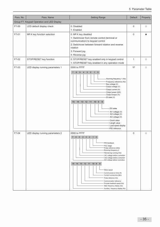
Group F7: Keypad Operation and LED Display
F7-00 LED default display check 0: Disabled1: Enabled
0
F7-01 MFK key function selection 0: MFK key disabled1: Switchover from remote control (terminal or communication) to keypad control 2: Switchover between forward rotation and reverse rotation3: Forward jog4: Reverse jog
0
F7-02 STOP/RESET key function 0: STOP/RESET key enabled only in keypad control1: STOP/RESET key enabled in any operation mode
1
F7-03 LED display running parameters 1 0000 to FFFF
7 6 5 4 3 2 1 0
Running frequency 1 (Hz)
Frequency reference (Hz)Bus voltage (V)Output voltage (V)
Output current (A)Output power (kW)Output torque (%)DI state (V)
15 14 12 11 10 9 8
DO state
AI1 voltage (V)
Count valueLength valueLoad speed displayPID reference
13
AI2 voltage (V)AI3 voltage (V)
1F
F7-04 LED display running parameters 2 0000 to FFFF7 6 5 4 3 2 1 0
PID feedback
PLC stagePulse reference (kHz)Running frequency 2
Remaining running timeAI1 voltage before correctionAI2 voltage before correctionAI3 voltage before correction
15 14 12 11 10 9 8
Motor speed
Current power-on time (H)Current running time (Min)
Pulse reference (Hz)
Communication referenceEncoder feedback speed (Hz)Main frequency display (Hz)
Auxiliary frequency display (Hz)
13
0

5 Parameter Table
- 36 -
Para No Para Name Setting Range Default Property
F7-05 LED display stop parameters 0000 to FFFF
7 6 5 4 3 2 1 0
Bus voltage (V)
DO stateAI1 voltage (V)
Count value
Frequency reference (Hz)
DI state
AI2 voltage (V)AI3 voltage (V)
15 14 12 11 10 9 8
PLC stage
Pulse reference (kHz)
Length value
Reserved
13
Load speedPID reference
ReservedReserved
33
F7-06 Load speed display decimal point coefficient
0001 to 65000 1000
F7-07 Heatsink temperature of inverter IGBT -20°C to 120°C -
F7-08 Product SN - -
F7-09 Accumulative running time 0 to 65535 h -
F7-10 Performance software version - -
F7-11 Function software version - -
F7-12 Number of decimal places for load speed display
10 to 23
1: 1 decimal place2: 2 decimal places
Number of decimal places of U0-140: 0 decimal place1: 1 decimal place2: 2 decimal places3: 3 decimal places
Number of decimal places of U0-19/U0-29
21
F7-13 Accumulative power-on time 0 to 65535 h -
F7-14 Accumulative power consumption 0 to 65535 kWh -

5 Parameter Table
- 37 -
Para No Para Name Setting Range Default Property
Group F8: Auxiliary Functions
F8-00 Jog frequency reference 000 Hz to max frequency 200 Hz
F8-01 Jog acceleration time 00s to 65000s 200s
F8-02 Jog deceleration time 00s to 65000s 200s
F8-03 Acceleration time 2 00s to 65000s Model dependent
F8-04 Deceleration time 2 00s to 65000s Model dependent
F8-05 Acceleration time 3 00s to 65000s Model dependent
F8-06 Deceleration time 3 00s to 65000s Model dependent
F8-07 Acceleration time 4 00s to 65000s 00s
F8-08 Deceleration time 4 00s to 65000s 00s
F8-09 Frequency jump 1 000 Hz to max frequency 000 Hz
F8-10 Frequency jump 2 000 Hz to max frequency 000 Hz
F8-11 Frequency jump band 000 Hz to max frequency 000 Hz
F8-12 Forward/Reverse run switchover dead-zone time
00s to 30000s 00s
F8-13 Reverse RUN selection 0: Disabled1: Enabled
0
F8-14 Running mode when frequency reference lower than frequency lower limit
0: Run at frequency reference lower limit1: Stop2: Run at zero speed
0
F8-15 Droop rate 00% to 1000%00% to 1000% correspond to 000 to 1000 on operating panel
000%
F8-16 Accumulative power-on time threshold 0 to 65000 h 0 h
F8-17 Accumulative running time threshold 0 to 65000 h 0 h
F8-18 Startup protection selection 0: Disabled1: Enabled
0
F8-19 Frequency detection value 1 000 Hz to max frequency 5000 Hz
F8-20 Frequency detection hysteresis 1 00% to 1000% 50%
F8-21 Detection width of target frequency reached
00% to 1000% 00%
F8-22 Jump frequency function 0: Disabled1: Enabled
0
F8-25 Switchover frequency of accel time 1 and accel time 2
000 Hz to max frequency 000 Hz
F8-26 Switchover frequency of decel time 1 and decel time 2
000 Hz to max frequency 000 Hz
F8-27 Set highest priority to terminal JOG function
0: Disabled1: Enabled
0
F8-28 Frequency detection value 2 000 Hz to max frequency 5000 Hz
F8-29 Frequency detection hysteresis 2 00% to 1000% 50%
F8-30 Detection of frequency 1 000 Hz to max frequency 5000 Hz

5 Parameter Table
- 38 -
Para No Para Name Setting Range Default Property
F8-31 Detection width of frequency 1 00% to 1000% (max frequency) 00%
F8-32 Detection of frequency 2 000 Hz to max frequency 5000 Hz
F8-33 Detection width of frequency 2 00% to 1000% (max frequency) 00%
F8-34 Zero current detection level 00% to 3000% (rated motor current) 50%
F8-35 Zero current detection delay 001s to 60000s 010s
F8-36 Output overcurrent threshold 00% (no detection)01% to 3000% (rated motor current)
2000%
F8-37 Output overcurrent detection delay 000s to 60000s 000s
F8-38 Detection level of current 1 00% to 3000% (rated motor current) 1000%
F8-39 Detection width of current 1 00% to 3000% (rated motor current) 00%
F8-40 Detection level of current 2 00% to 3000% (rated motor current) 1000%
F8-41 Detection width of current 2 00% to 3000% (rated motor current) 00%
F8-42 Timing function 0: Disabled1: Enabled
0
F8-43 Running time setting channel 0 to 3 0
F8-44 Running time 00 to 65000 min 00 min
F8-45 AI1 input voltage lower limit 000 V to F8-46 310 V
F8-46 AI1 input voltage upper limit F8-45 to 1000 V 680 V
F8-47 IGBT temperature threshold 0°C to 100°C 75°C
F8-48 Cooling fan working mode 0: Working during drive running1: Working continuously
0
F8-49 Wakeup frequency F8-51 to max frequency (F0-10) 000 Hz
F8-50 Wakeup delay time 00s to 65000s 00s
F8-51 Hibernating frequency 000 Hz to wakeup frequency (F8-49) 000 Hz
F8-52 Hibernating delay time 00s to 65000s 00s
F8-53 Running time threshold this time 00 to 65000 min 00 min
F8-54 Output power correction coefficient 00% to 2000% 1000%
F8-55 Emergency stop time 0 to 65535 Model dependent
Group F9: Fault and Protection
F9-00 Motor overload protection 0: Disabled1: Enabled
1
F9-01 Motor overload protection gain 020 to 1000 100
F9-02 Motor overload pre-warning coefficient 50% to 100% 80%
F9-07 Detection of short-circuit to ground upon power-on
Short-circuit to ground protection before running0: Disabled1: Enabled
Short-circuit to ground protection at power-on0: Disabled1: Enabled
01
5 Parameter Table
- 39 -
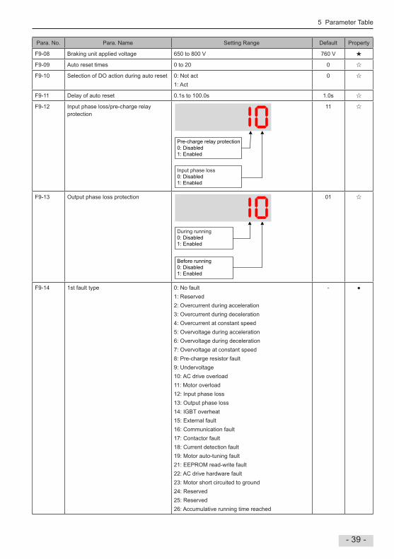
Para No Para Name Setting Range Default Property
F9-08 Braking unit applied voltage 650 to 800 V 760 V
F9-09 Auto reset times 0 to 20 0
F9-10 Selection of DO action during auto reset 0: Not act1: Act
0
F9-11 Delay of auto reset 01s to 1000s 10s
F9-12 Input phase loss/pre-charge relay protection
0: Disabled1: Enabled
Input phase loss0: Disabled1: Enabled
Pre-charge relay protection
11
F9-13 Output phase loss protection
During running0: Disabled1: Enabled
Before running0: Disabled1: Enabled
01
F9-14 1st fault type 0: No fault1: Reserved2: Overcurrent during acceleration3: Overcurrent during deceleration4: Overcurrent at constant speed5: Overvoltage during acceleration6: Overvoltage during deceleration7: Overvoltage at constant speed8: Pre-charge resistor fault9: Undervoltage10: AC drive overload11: Motor overload12: Input phase loss13: Output phase loss14: IGBT overheat15: External fault16: Communication fault17: Contactor fault18: Current detection fault19: Motor auto-tuning fault21: EEPROM read-write fault22: AC drive hardware fault23: Motor short circuited to ground24: Reserved25: Reserved26: Accumulative running time reached
-

5 Parameter Table
- 40 -
Para No Para Name Setting Range Default Property
F9-15 2nd fault type 27: User-defined fault 128: User-defined fault 229: Accumulative power-on time reached30: Load loss31: PID feedback lost during running40: Pulse-by-pulse current limit fault41: Motor switchover fault during running42: Reserved43: Reserved55: Slave fault in master/slave control
-
F9-16 3rd (latest) fault type -
F9-17 Frequency upon 3rd fault - -
F9-18 Current upon 3rd fault - -
F9-19 Bus voltage upon 3rd fault - -
F9-20 DI state upon 3rd fault - -
F9-21 DO state upon 3rd fault - -
F9-22 AC drive state upon 3rd fault - -
F9-23 Power-on time upon 3rd fault - -
F9-24 Running time upon 3rd fault - -
F9-27 Frequency upon 2nd fault - -
F9-28 Current upon 2nd fault - -
F9-29 Bus voltage upon 2nd fault - -
F9-30 DI state upon 2nd fault - -
F9-31 DO state upon 2nd fault - -
F9-32 AC drive state upon 2nd fault - -
F9-33 Power-on time upon 2nd fault - -
F9-34 Running time upon 2nd fault - -
F9-37 Frequency upon 1st fault - -
F9-38 Current upon 1st fault - -
F9-39 Bus voltage upon 1st fault - -
F9-40 DI state upon 1st fault - -
F9-41 DO state upon 1st fault - -
F9-42 AC drive state upon 1st fault - -
F9-43 Power-on time upon 1st fault - -
F9-44 Running time upon 1st fault - -

5 Parameter Table
- 41 -
Para No Para Name Setting Range Default Property
F9-47 Fault protection action selection 1 00000 to 22222
Input phase loss (Err12):Same as that of units position
Motor overload (Err11):0: Coast to stop1: Stop according to stop mode2: Continue to run
Output phase loss (Err13):Same as that of units position
Communication fault (Err16):Same as that of units position
External fault (Err15):Same as that of units position
00000
F9-48 Fault protection action selection 2 00000 to 11111
EEPROM read-write fault (Err21):0: Coast to stop1: Stop according to stop mode
Encoder fault (Err20):0: Coast to stop1: Switch over to V/F control, stop according to stop mode2: Switch over to V/F control, continue to run
Reserved
Accumulative running time reached (Err26):0: Coast to stop1: Stop according to stop mode2: Continue to run
Motor overheat (Err25):0: Coast to stop1: Stop according to stop mode2: Continue to run
00000

5 Parameter Table
- 42 -
Para No Para Name Setting Range Default Property
F9-49 Fault protection action selection 3 00000 to 22222
User-defined fault 1 (Err27):0: Coast to stop1: Stop according to stop mode2: Continue to run
Accumulative power-on time reached (Err29):0: Coast to stop1: Stop according to stop mode2: Continue to run
PID feedback lost during running (Err31):0: Coast to stop1: Stop according to stop mode2: Continue to run
Load loss (Err30):0: Coast to stop1: Decelerate to stop2: Continue to run at 7% of rated motor frequency and restore to the frequency reference if the load recovers
User-defined fault 2 (Err28):0: Coast to stop1: Stop according to stop mode2: Continue to run
00000
F9-54 Frequency selection for continuing to run upon fault
0: Current running frequency1: Frequency reference2: Frequency upper limit3: Frequency lower limit4: Backup frequency upon abnormality
0
F9-55 Backup frequency upon fault 00% to 1000% (max frequency) 1000%
F9-56 Type of motor temperature sensor 0: No temperature sensor1: PT1002: PT1000
0
F9-57 Motor overheat protection threshold 0°C to 200°C 110°C
F9-58 Motor overheat pre-warning threshold 0°C to 200°C 90°C
F9-59 Power dip ride-through function selection
0: Disabled1: Bus voltage constant control2: Decelerate to stop
0
F9-60 Threshold of power dip ride-through function disabled
80% to 100% 85%
F9-61 Judging time of bus voltage recovering from power dip
00s to 1000s 05s
F9-62 Threshold of power dip ride-through function enabled
60% to 100% 80%
F9-63 Load lost protection 0: Disabled1: Enabled
0
F9-64 Load lost detection level 00% to 1000% 100%
F9-65 Load lost detection time 00s to 600s 10s
F9-71 Power dip ride-through gain Kp 0 to 100 40
F9-72 Power dip ride-through integral coefficient
0 to 100 30
F9-73 Deceleration time of power dip ride-through
00s to 3000s 200s

5 Parameter Table
- 43 -
Para No Para Name Setting Range Default Property
Group FA: PID Function
FA-00 PID reference setting channel 0: Set by FA-011: AI12: AI23: AI34: Pulse reference (DI5)5: Serial comms6: Multi-reference
0
FA-01 PID digital setting 00% to 1000% 500%
FA-02 PID feedback setting channel 0: AI11: AI22: AI33: AI1 - AI24: Pulse reference (DI5)5: Serial comms6: AI1 + AI27: Max (|AI1|, |AI2|)8: Min (|AI1|, |AI2|)
0
FA-03 PID operation direction 0: Forward1: Reverse
0
FA-04 PID reference and feedback range 0 to 65535 1000
FA-05 Proportional gain Kp1 00 to 10000 200
FA-06 Integral time Ti1 001s to 1000s 200s
FA-07 Differential time Td1 0000s to 10000s 0000s
FA-08 PID output limit in reverse direction 000 Hz to max frequency 000 Hz
FA-09 PID error limit 00% to 1000% 00%
FA-10 PID differential limit 000% to 10000% 010%
FA-11 PID reference change time 000s to 65000s 000s
FA-12 PID feedback filter time 000s to 6000s 000s
FA-13 PID output filter time 000s to 6000s 000s
FA-14 Reserved - - -
FA-15 Proportional gain Kp2 00 to 10000 200
FA-16 Integral time Ti2 001s to 1000s 200s
FA-17 Differential time Td2 0000s to 10000s 0000s
FA-18 PID parameter switchover condition 0: No switchover1: Switchover via DI2: Auto switchover based on PID error3: Auto switchover based on running frequency
0
FA-19 PID error 1 for auto switchover 00% to FA-20 200%
FA-20 PID error 2 for auto switchover FA-19 to 1000% 800%
FA-21 PID initial value 00% to 1000% 00%
FA-22 PID initial value active time 000s to 65000s 000s

5 Parameter Table
- 44 -
Para No Para Name Setting Range Default Property
FA-25 PID integral property 00 to 11
Whether to stop integral operation when PID output reaches the limit0: Continue integral operation1: Stop integral operation
Integral separation0: Disabled1: Enabled
00
FA-26 Detection level of PID feedback loss 00%: No detection01% to 1000%
00%
FA-27 Detection time of PID feedback loss 00s to 200s 00s
FA-28 Selection of PID operation at stop 0: Disabled1: Enabled
0
Group Fb: Wobble Function, Fixed Length and Count
Fb-00 Wobble setting mode 0: Relative to the frequency reference1: Relative to the max frequency
0
Fb-01 Wobble amplitude 00% to 1000% 00%
Fb-02 Wobble step 00% to 500% 00%
Fb-03 Wobble cycle 00s to 30000s 100s
Fb-04 Triangular wave rising time coefficient 00% to 1000% 500%
Fb-05 Set length 0 to 65535 m 1000 m
Fb-06 Actual length 0 to 65535 m 0 m
Fb-07 Number of pulses per meter 01 to 65535 1000
Fb-08 Set count value 1 to 65535 1000
Fb-09 Designated count value 1 to 65535 1000
Group FC: Multi-Reference and Simple PLC Function
FC-00 Reference 0 -1000% to 1000% 00%
FC-01 Reference 1 -1000% to 1000% 00%
FC-02 Reference 2 -1000% to 1000% 00%
FC-03 Reference 3 -1000% to 1000% 00%
FC-04 Reference 4 -1000% to 1000% 00%
FC-05 Reference 5 -1000% to 1000% 00%
FC-06 Reference 6 -1000% to 1000% 00%
FC-07 Reference 7 -1000% to 1000% 00%
FC-08 Reference 8 -1000% to 1000% 00%
FC-09 Reference 9 -1000% to 1000% 00%
FC-10 Reference 10 -1000% to 1000% 00%
FC-11 Reference 11 -1000% to 1000% 00%
FC-12 Reference 12 -1000% to 1000% 00%
FC-13 Reference 13 -1000% to 1000% 00%

5 Parameter Table
- 45 -
Para No Para Name Setting Range Default Property
FC-10 Reference 10 -1000% to 1000% 00%
FC-11 Reference 11 -1000% to 1000% 00%
FC-12 Reference 12 -1000% to 1000% 00%
FC-13 Reference 13 -1000% to 1000% 00%
FC-14 Reference 14 -1000% to 1000% 00%
FC-15 Reference 15 -1000% to 1000% 00%
FC-16 Simple PLC running mode 0: Stop after running one cycle1: Keep final values after running one cycle2: Repeat after running one cycle
0
FC-17 Simple PLC retentive selection 00 to 11
Retentive at stop0: Not retentive1: Retentive
Retentive at power down0: Not retentive1: Retentive
00
FC-18 Running time of simple PLC reference 0 00s (h) to 65535s (h) 00s (h)
FC-19 Acceleration/deceleration time of simple PLC reference 0
0 to 3 0
FC-20 Running time of simple PLC reference 1 00s (h) to 65535s (h) 00s (h)
FC-21 Acceleration/deceleration time of simple PLC reference 1
0 to 3 0
FC-22 Running time of simple PLC reference 2 00s (h) to 65535s (h) 00s (h)
FC-23 Acceleration/deceleration time of simple PLC reference 2
0 to 3 0
FC-24 Running time of simple PLC reference 3 00s (h) to 65535s (h) 00s (h)
FC-25 Acceleration/deceleration time of simple PLC reference 3
0 to 3 0
FC-26 Running time of simple PLC reference 4 00s (h) to 65535s (h) 00s (h)
FC-27 Acceleration/deceleration time of simple PLC reference 4
0 to 3 0
FC-28 Running time of simple PLC reference 5 00s (h) to 65535s (h) 00s (h)
FC-29 Acceleration/deceleration time of simple PLC reference 5
0 to 3 0
FC-30 Running time of simple PLC reference 6 00s (h) to 65535s (h) 00s (h)
FC-31 Acceleration/deceleration time of simple PLC reference 6
0 to 3 0
FC-32 Running time of simple PLC reference 7 00s (h) to 65535s (h) 00s (h)
FC-33 Acceleration/deceleration time of simple PLC reference 7
0 to 3 0
FC-34 Running time of simple PLC reference 8 00s (h) to 65535s (h) 00s (h)
FC-35 Acceleration/deceleration time of simple PLC reference 8
0 to 3 0

5 Parameter Table
- 46 -
Para No Para Name Setting Range Default Property
FC-36 Running time of simple PLC reference 9 00s (h) to 65535s (h) 00s (h)
FC-37 Acceleration/deceleration time of simple PLC reference 9
0 to 3 0
FC-38 Running time of simple PLC reference 10
00s (h) to 65535s (h) 00s (h)
FC-39 Acceleration/deceleration time of simple PLC reference 10
0 to 3 0
FC-40 Running time of simple PLC reference 11
00s (h) to 65535s (h) 00s (h)
FC-41 Acceleration/deceleration time of simple PLC reference 11
0 to 3 0
FC-42 Running time of simple PLC reference 12
00s (h) to 65535s (h) 00s (h)
FC-43 Acceleration/deceleration time of simple PLC reference 12
0 to 3 0
FC-44 Running time of simple PLC reference 13
00s (h) to 65535s (h) 00s (h)
FC-45 Acceleration/deceleration time of simple PLC reference 13
0 to 3 0
FC-46 Running time of simple PLC reference 14
00s (h) to 65535s (h) 00s (h)
FC-47 Acceleration/deceleration time of simple PLC reference 14
0 to 3 0
FC-48 Running time of simple PLC reference 15
00s (h) to 65535s (h) 00s (h)
FC-49 Acceleration/deceleration time of simple PLC reference 15
0 to 3 0
FC-50 Time unit of simple PLC running 0: s (second)1: h (hour)
0
FC-51 Reference 0 source 0: Set by FC-001: AI12: AI23: AI34: Pulse reference5: PID6: Set by preset frequency (F0-08), modified via terminal UP/DOWN
0

5 Parameter Table
- 47 -
Para No Para Name Setting Range Default Property
Group Fd: Communication
Fd-00 Baud rate 0000 to 6039
PROFIBUS-DP baud rate:0: 115200 bps1: 208300 bps2: 256000 bps3: 512000 bps
Modbus baud rate:0: 300 bps1: 600 bps2: 1200 bps3: 2400 bps4: 4800 bps5: 9600 bps6: 19200 bps7: 38400 bps8: 57600 bps9: 115200 bps
Initial position fault (Err51):Same as that of units position
CANlink baud rate:0: 20 Kbps1: 50 Kbps2: 100 Kbps3: 125 Kbps4: 250 Kbps5: 500 Kbps6: 1 Mbps
5005
Fd-01 Data format symbol 0: No check: data format <8, N, 2>1: Even parity check: data format <8, E, 1>2: Odd parity check: data format <8, O, 1>3: No check: data format <8, N, 1>
0
Fd-02 Local address 0: Broadcast address;1 to 247
1
Fd-03 Response delay 0 to 20 ms 2
Fd-04 Communication timeout 00s: invalid01s to 600sValid for Modbus, PROFIBUS-DP and CANlink
00s
Fd-05 Modbus protocol selection and PROFIBUS-DP data frame
00 to 31
PROFIBUS-DP data frame0: PPO1 format1: PPO2 format2: PPO3 format3: PPO5 format
Modbus protocol selection0: Non-standard Modbus protocol1: Standard Modbus protocol
30
Fd-06 Current resolution read by communication
0: 0.01 A (valid when ≤ 55 kW)1: 01 A
0
Fd-08 CANlink communication timeout time 00s (invalid)01s to 600s
0

5 Parameter Table
- 48 -
Para No Para Name Setting Range Default Property
Group FE: User-Defined Parameters
FE-00 User-defined parameter 0 F0-00 to FP-xx, A1-00 to Ax-xx, U0-00 to U0-xx F0-00
FE-01 User-defined parameter 1 F0-02
FE-02 User-defined parameter 2 F0-03
FE-03 User-defined parameter 3 F0-07
FE-04 User-defined parameter 4 F0-08
FE-05 User-defined parameter 5 F0-17
FE-06 User-defined parameter 6 F0-18
FE-07 User-defined parameter 7 F3-00
FE-08 User-defined parameter 8 F3-01
FE-09 User-defined parameter 9 F4-00
FE-10 User-defined parameter 10 F4-01
FE-11 User-defined parameter 11 F4-02
FE-12 User-defined parameter 12 F5-04
FE-13 User-defined parameter 13 F5-07
FE-14 User-defined parameter 14 F6-00
FE-15 User-defined parameter 15 F6-10
FE-16 User-defined parameter 16 F0-00
FE-17 User-defined parameter 17 F0-00
FE-18 User-defined parameter 18 F0-00
FE-19 User-defined parameter 19 F0-00
FE-20 User-defined parameter 20 F0-00
FE-21 User-defined parameter 21 F0-00
FE-22 User-defined parameter 22 F0-00
FE-23 User-defined parameter 23 F0-00
FE-24 User-defined parameter 24 F0-00
FE-25 User-defined parameter 25 F0-00
FE-26 User-defined parameter 26 F0-00
FE-27 User-defined parameter 27 F0-00
FE-28 User-defined parameter 28 F0-00
FE-29 User-defined parameter 29 F0-00
Group FF: Manufacturer Parameters, Access Denied
5 Parameter Table
- 49 -
Para No Para Name Setting Range Default Property
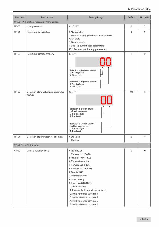
Group FP: Function Parameter Management
FP-00 User password 0 to 65535 0
FP-01 Parameter initialization 0: No operation1: Restore factory parameters except motor parameters2: Clear records4: Back up current user parameters501: Restore user backup parameters
0
FP-02 Parameter display property 00 to 11
Selection of display of group A0: Not displayed1: Displayed
Selection of display of group U0: Not displayed1: Displayed
11
FP-03 Selection of individualized parameter display
00 to 11
Selection of display of user defined parameters0: Not displayed1: Displayed
Selection of display of user modified parameters0: Not displayed1: Displayed
00
FP-04 Selection of parameter modification 0: Disabled1: Enabled
0
Group A1: Virtual DI/DO
A1-00 VDI1 function selection 0: No function1: Forward run (FWD)2: Reverser run (REV)3: Three-wire control4: Forward jog (FJOG)5: Reverse jog (RJOG)6: Terminal UP7: Terminal DOWN8: Coast to stop9: Fault reset (RESET)10: RUN disabled11: External fault normally-open input12: Multi-reference terminal 113: Multi-reference terminal 214: Multi-reference terminal 315: Multi-reference terminal 4
0

5 Parameter Table
- 50 -
Para No Para Name Setting Range Default Property
A1-01 VDI2 function selection 16: Terminal 1 for acceleration/deceleration time selection17: Terminal 2 for acceleration/deceleration time selection18: Frequency reference setting channel switchover19: UP and DOWN setting clear (terminal, operation panel)20: Command source switchover 121: Acceleration/Deceleration prohibited22: PID disabled23: PLC state reset24: Wobble disabled25: Counter input26: Counter reset27: Length signal pulses count28: Length reset30: Pulse input as frequency reference (valid only for DI5)31: Reserved32: Immediate DC injection braking33: External fault normally-closed input34: Frequency modification enabled35: PID operation direction reverse36: External stop 137: Command source switchover 238: PID integral disabled39: Switchover between main frequency reference and preset frequency40: Switchover between auxiliary frequency reference and preset frequency41: Motor selection42: Reserved43: PID parameter switchover44: User-defined fault 145: User-defined fault 247: Emergency stop (ES)48: External stop 249: Deceleration DC injection braking50: Clear running time this time51: Two-wire control/ Three-wire control52: Reverse running prohibited53 to 59: Reserved
0
A1-02 VDI3 function selection 0
A1-03 VDI4 function selection 0
A1-04 VDI5 function selection 0

5 Parameter Table
- 51 -
Para No Para Name Setting Range Default Property
A1-05 VDI active state setting mode 00000 to 11111
VDI2:0: Decided by state of VDOx1: Decided by A1-06
VDI1:0: Decided by state of VDOx1: Decided by A1-06
VDI3:0: Decided by state of VDOx1: Decided by A1-06
VDI5:0: Decided by state of VDOx1: Decided by A1-06
VDI4:0: Decided by state of VDOx1: Decided by A1-06
00000
A1-06 Selection of VDI active state 00000 to 11111
VDI2:0: Inactive1: Active
VDI1:0: Inactive1: Active
VDI3:0: Inactive1: Active
VDI5:0: Inactive1: Active
VDI4:0: Inactive1: Active
00000
A1-07 Function selection for AI1 used as DI 0: No function1: Forward run (FWD)2: Reverser run (REV)3: Three-wire control4: Forward jog (FJOG)5: Reverse jog (RJOG)6: Terminal UP7: Terminal DOWN8: Coast to stop9: Fault reset (RESET)10: RUN disabled11: External fault normally-open input12: Multi-reference terminal 113: Multi-reference terminal 214: Multi-reference terminal 315: Multi-reference terminal 416: Terminal 1 for acceleration/deceleration time selection
0

5 Parameter Table
- 52 -
Para No Para Name Setting Range Default Property
A1-08 Function selection for AI2 used as DI 17: Terminal 2 for acceleration/deceleration time selection18: Frequency reference setting channel switchover19: UP and DOWN setting clear (terminal, operation panel)20: Command source switchover 121: Acceleration/Deceleration prohibited22: PID disabled23: PLC state reset24: Wobble disabled25: Counter input26: Counter reset27: Length signal pulses count28: Length reset30: Pulse input as frequency reference (valid only for DI5)31: Reserved32: Immediate DC injection braking33: External fault normally-closed input34: Frequency modification enabled35: PID operation direction reverse36: External stop 137: Command source switchover 238: PID integral disabled39: Switchover between main frequency reference and preset frequency40: Switchover between auxiliary frequency reference and preset frequency41: Motor selection42: Reserved43: PID parameter switchover44: User-defined fault 145: User-defined fault 247: Emergency stop (ES)48: External stop 249: Deceleration DC injection braking50: Clear running time this time51: Two-wire control/ Three-wire control52: Reverse running prohibited53 to 59: Reserved
0
A1-09 Function selection for AI3 used as DI 0
A1-10 Active state selection for AI used as DI 000 to 111
AI20: High level active1: Low level active
AI10: High level active1: Low level active
AI30: High level active1: Low level active
000

5 Parameter Table
- 53 -
Para No Para Name Setting Range Default Property
A1-11 VDO1 function selection 0: No output1: AC drive running2: Fault output3: Frequency level detection 1 output4: Frequency reached5: Zero-speed running (no output at stop)6: Motor overload pending7: AC drive overload pending8: Set count value reached9: Designated count value reached10: Length reached11: PLC cycle completed12: Accumulative running time reached13: Frequency limited15: Ready for RUN16: AI1 > AI217: Frequency upper limit reached18: Frequency lower limit reached (no output at stop)19: Undervoltage20: Communication setting21: Reserved22: Reserved23: Zero-speed running 2 (having output at stop)24: Accumulative power-on time reached25: Frequency level detection 226: Frequency 1 reached27: Frequency 2 reached28: Current 1 reached29: Current 2 reached30: Timing reached31: AI1 input exceeding limit32: Load lost33: Reverse running34: Zero current35: IGBT temperature reached36: Output current exceeding limit37: Frequency lower limit reached (having output at stop)38: Alarm output39: Motor overheat pending40: Current running time reached41: Fault output
0
A1-12 VDO2 function selection 0
A1-13 VDO3 function selection 0
A1-14 VDO4 function selection 0
A1-15 VDO5 function selection 0
A1-16 VDO1 output delay 00s to 36000s 00s
A1-17 VDO2 output delay 00s to 36000s 00s
A1-18 VDO3 output delay 00s to 36000s 00s
A1-19 VDO4 output delay 00s to 36000s 00s
A1-20 VDO5 output delay 00s to 36000s 00s

5 Parameter Table
- 54 -
Para No Para Name Setting Range Default Property
A1-21 VDO active mode selection 00000 to 11111
VDO2:0: Positive logic active1: Negative logic active
VDO1:0: Positive logic active1: Negative logic active
VDO3:0: Positive logic active1: Negative logic active
VDO5:0: Positive logic active1: Negative logic active
VDO4:0: Positive logic active1: Negative logic active
00000
Group A2: Motor 2 Parameters
A2-00 Motor type selection 0 to 1 0
A2-01 Rated motor power 01 to 10000 kW Model dependent
A2-02 Rated motor voltage 1 to 2000 V Model dependent
A2-03 Rated motor current 0.01 to 655.35 A (AC drive power ≤ 55 kW) 01 to 65535 A (AC drive power > 55 kW)
Model dependent
A2-04 Rated motor frequency 001 Hz to max frequency Model dependent
A2-05 Rated motor speed 1 to 65535 rpm Model dependent
A2-06 Stator resistance 0.001 to 65.535 Ω (AC drive power ≤ 55 kW) 0.0001 to 6.5535 Ω (AC drive power > 55 kW)
Auto-tuning dependent
A2-07 Rotor resistance 0.001 to 65.535 Ω (AC drive power ≤ 55 kW)
0.0001 to 6.5535 Ω (AC drive power > 55 kW)
Auto-tuning dependent
A2-08 Leakage inductive reactance 0.01 to 655.35 mH (AC drive power ≤ 55 kW)
0001 to 65535 mH (AC drive power > 55 kW)
Auto-tuning dependent
A2-09 Mutual inductive reactance 0.1 to 6553.5 mH (AC drive power ≤ 55 kW)001 to 65535 mH (AC drive power > 55 kW)
Auto-tuning dependent
A2-10 No-load current 0.01 A to A2-03 (AC drive power ≤ 55 kW)01 A to A2-03 (AC drive power > 55 kW)
Auto-tuning dependent
A2-37 Motor auto-tuning method selection 0: No auto-tuning1: Static auto-tuning 12: Dynamic auto-tuning3: Static auto-tuning 2
0
A2-62 Motor 2 control mode 0: SVC control1: FVC control2: V/F control
0

5 Parameter Table
- 55 -
Para No Para Name Setting Range Default Property
A2-63 Motor 2 acceleration/deceleration time selection
0: The same motor 12: Acceleration/deceleration time 23: Acceleration/deceleration time 34: Acceleration/deceleration time 4
0
A2-64 Motor 2 torque boost 0.0%: fixed torque boost01% to 300%
Model dependent
A2-66 Motor 2 oscillation suppression gain 0 to 100 40
Group A5: Control Optimization
A5-00 DPWM switchover frequency upper limit
500 Hz to max frequency 800 Hz
A5-01 PWM modulation pattern 0: Asynchronous modulation1: Synchronous modulation
0
A5-02 Dead zone compensation mode selection
0: No compensation1: Compensation mode 1
1
A5-03 Random PWM depth 0 to 10 0
A5-04 Overcurrent fast prevention 0: Disabled1: Enabled
1
A5-05 Max. output voltage coefficient 100% to 110% 105%
A5-06 Undervoltage threshold 210 to 420 V 350 V
A5-08 Dead-zone time adjustment 100% to 200% 150%
A5-09 Overvoltage threshold 2000 to 25000 V Model dependent
A5-10 Energy saving control 0: Disabled1: Enabled
0
Group A6: AI Curve Setting
A6-00 AI curve 4 min input -1000 V to A6-02 000 V
A6-01 Corresponding percentage of AI curve 4 min input
-1000% to 1000% 00%
A6-02 AI curve 4 inflexion 1 input A6-00 to A6-04 300 V
A6-03 Corresponding percentage of AI curve 4 inflexion 1 input
-1000% to 1000% 300%
A6-04 AI curve 4 inflexion 2 input A6-02 to A6-06 600 V
A6-05 Corresponding percentage of AI curve 4 inflexion 2 input
-1000% to 1000% 600%
A6-06 AI curve 4 max input A6-04 to 1000 V 1000 V
A6-07 Corresponding percentage of AI curve 4 max input
-1000% to 1000% 1000%
A6-08 AI curve 5 min input -1000 V to A6-10 -1000 V
A6-09 Corresponding percentage of AI curve 5 min input
-1000% to 1000% -1000%
A6-10 AI curve 5 inflexion 1 input A6-08 to A6-12 -300 V
A6-11 Corresponding percentage of AI curve 5 inflexion 1 input
-1000% to 1000% -300%
A6-12 AI curve 5 inflexion 2 input A6-10 to A6-14 300 V

5 Parameter Table
- 56 -
Para No Para Name Setting Range Default Property
A6-13 Corresponding percentage of AI curve 5 inflexion 2 input
-1000% to 1000% 300%
A6-14 AI curve 5 max input A6-12 to 1000 V 1000 V
A6-15 Corresponding percentage of AI curve 5 max input
-1000% to 1000% 1000%
A6-24 Jump point of AI1 input corresponding setting
-1000% to 1000% 00%
A6-25 Jump amplitude of AI1 input corresponding setting
00% to 1000% 05%
A6-26 Jump point of AI2 input corresponding setting
-1000% to 1000% 00%
A6-27 Jump amplitude of AI2 input corresponding setting
00% to 1000% 05%
A6-28 Jump point of AI3 input corresponding setting
-1000% to 1000% 00%
A6-29 Jump amplitude of AI3 input corresponding setting
00% to 1000% 05%
Group A7: User Programmable Card
A7-00 User programmable function selection 0: Disabled1: Enabled
0
A7-01 AC drive output terminal control source selection
00000 to 11111
Relay (T/A-T/B-T/C):0: AC drive control1: User programmable card control
FMR (FM used as digital output):0: AC drive control1: User programmable card control
DO1:0: AC drive control1: User programmable card control
AO1:0: AC drive control1: User programmable card control
FMP (FM used as pulse output):0: AC drive control1: User programmable card control
00000
A7-02 User programmable card AI3 and AO2 function selection
0: AI3 (voltage input), AO2 (voltage output)
1: AI3 (voltage input), AO2 (current output)
2: AI3 (current input), AO2 (voltage output)
3: AI3 (current input), AO2 (current output)
4: AI3 (PTC input), AO2 (voltage output)
5: AI3 (PTC input), AO2 (current output)
6: AI3 (PT100 input), AO2 (voltage output)
7: AI3 (PT100 input), AO2 (current output)
0
A7-03 PLC program controls the FMP output 00% to 1000% 00%
A7-04 PLC program controls the AO1 output 00% to 1000% 00%

5 Parameter Table
- 57 -
Para No Para Name Setting Range Default Property
A7-05 Selection of PLC program controlling digital output
000 to 111
Relay10: Disabled1: Enabled
FMR0: Disabled1: Enabled
DO0: Disabled1: Enabled
000
A7-06 Setting frequency reference via the user programmable card
-10000% to 10000% 000%
A7-08 Setting running command via the user programmable card
0: No command1: Forward run2: Reverse run3: Forward jog4:Reverse jog5: Coast to stop6: Decelerate to stop7: Fault reset
0
A7-09 Setting fault via the user programmable card
0: No fault 80 to 89: fault code
0
Group A8: Point-point Communication
A8-00 Point-point communication 0: Disabled1: Enabled
0
A8-01 Master or slave selection 0: Master1: Slave
0
A8-02 Selection of action of the slave in point-point communication
000 to 111
Whether to send fault information to master when a fault occurs0: No1: Yes
Whether to follow master command0: No1: Yes
Whether to alarm when it becomes offline0: No1: Yes
011
A8-03 The slave received data 0: Output frequency1: Frequency reference
0
A8-04 Zero offset of received data -10000 to 10000 000
A8-05 Gain of received data -1000 to 1000 100

5 Parameter Table
- 58 -
Para No Para Name Setting Range Default Property
A8-06 Point-point communication interruption detection time
00s to 100s 10s
A8-07 Master data sending cycle in point-point communication
0001s to 10000s 0001s
A8-08 Zero offset of receiving data (frequency) -10000% to 10000% 000%
A8-09 Gain of receiving data (frequency) -1000 to 10000 100
A8-10 Runaway prevention coefficient 000% to 10000% 1000%
A8-11 Window width 020 to 1000 Hz 050 Hz
Group AC: AI/AO Correction
AC-00 AI1 measured voltage 1 -1000 to 10000 V Factory-corrected
AC-01 AI1 displayed voltage 1 -1000 to 10000 V Factory-corrected
AC-02 AI1 measured voltage 2 -1000 to 10000 V Factory-corrected
AC-03 AI1 displayed voltage 2 -1000 to 10000 V Factory-corrected
AC-04 AI2 measured voltage 1 -1000 to 10000 V Factory-corrected
AC-05 AI2 displayed voltage 1 -1000 to 10000 V Factory-corrected
AC-06 AI2 measured voltage 2 -1000 to 10000 V Factory-corrected
AC-07 AI2 displayed voltage 2 -1000 to 10000 V Factory-corrected
AC-08 AI3 measured voltage 1 -1000 to 10000 V Factory-corrected
AC-09 AI3 displayed voltage 1 -1000 to 10000 V Factory-corrected
AC-10 AI3 measured voltage 2 -1000 to 10000 V Factory-corrected
AC-11 AI3 displayed voltage 2 -1000 to 10000 V Factory-corrected
AC-12 AO1 target voltage 1 -1000 to 10000 V Factory-corrected
AC-13 AO1 measured voltage 1 -1000 to 10000 V Factory-corrected
AC-14 AO1 target voltage 2 -1000 to 10000 V Factory-corrected
AC-15 AO1 measured voltage 2 -1000 to 10000 V Factory-corrected
AC-16 AO2 target voltage 1 -1000 to 10000 V Factory-corrected
AC-17 AO2 measured voltage 1 -1000 to 10000 V Factory-corrected
AC-18 AO2 target voltage 2 -1000 to 10000 V Factory-corrected

5 Parameter Table
- 59 -
Para No Para Name Setting Range Default Property
AC-19 AO2 measured voltage 2 -1000 to 10000 V Factory-corrected
AC-20 AI2 measured current 1 0000 to 20000 mA Factory-corrected
AC-21 AI2 sampling current 1 0000 to 20000 mA Factory-corrected
AC-22 AI2 measured current 2 0000 to 20000 mA Factory-corrected
AC-23 AI2 sampling current 2 0000 to 20000 mA Factory-corrected
AC-24 AO1 ideal current 1 0000 to 20000 mA Factory-corrected
AC-25 AO1 measured current 1 0000 to 20000 mA Factory-corrected
AC-26 AO1 ideal current 2 0000 to 20000 mA Factory-corrected
AC-27 AO1 measured current 2 0000 to 20000 mA Factory-corrected
53 Monitoring Function Code
Para No Para Name Display Range
Group U0: Monitoring Parameters
U0-00 Running frequency 000 to 5000 Hz
U0-01 Frequency reference 000 to 5000 Hz
U0-02 Bus voltage 00 to 30000 V
U0-03 Output voltage 0 to 1140 V
U0-04 Output current 000 to 65535 A
U0-05 Output power 0 to 32767
U0-07 DI state 0 to 32767
U0-08 DO state 0 to 1023
U0-09 AI1 voltage -
U0-10 AI2 voltage -
U0-11 AI3 voltage -
U0-12 Count value -
U0-13 length value -
U0-14 Load speed display 0 to rated motor speed
U0-15 PID reference 0 to 65535
U0-16 PID feedback 0 to 65535
U0-17 PLC stage -
U0-18 Pulse reference 000 to 2000 kHz
U0-19 Feedback speed -5000 to 5000 Hz
U0-20 Remaining running time 00 to 65000 min
U0-21 AI1 voltage before correction 000 to 1057 V
U0-22 AI2 voltage (V)/ current (mA) before correction
000 to 1057 V
U0-23 AI3 voltage before correction -1057 to 1057 V

5 Parameter Table
- 60 -
Para No Para Name Display Range
U0-24 Motor speed 0 to rated motor speed
U0-25 Accumulative power-on time -
U0-26 Accumulative running time -
U0-27 Pulse reference 0 to 65535 Hz
U0-28 Communication reference -10000% to 10000%
U0-30 Main frequency reference 000 to 50000 Hz
U0-31 Auxiliary frequency reference 000 to 50000 Hz
U0-32 Viewing any register address value -
U0-34 Motor temperature -
U0-37 Power factor angle -180° to 180°
U0-39 Target voltage upon V/F separation 0 V to rated motor voltage
U0-40 Output voltage upon V/F separation 0 V to rated motor voltage
U0-41 DI state display -
U0-42 DO state display -
U0-43 DI set for function state display 1 -
U0-44 DI set for function state display 2 -
U0-45 Fault information 0 to 51
U0-59 Frequency Reference -10000% to 10000%
U0-60 Running frequency -10000% to 10000%
U0-61 AC drive state 0 to 65535
U0-62 Current fault code 0 to 99
U0-63 Master sending value of point-point communication
-
U0-64 Number of slaves 0 to 63
U0-66 Communication extension card type 100: CANopen200: PROFIBUS-DP300: CANlink
U0-67 Communication extension card version -
U0-68 AC drive status read via DP card -
U0-69 Speed of transmitting DP 000 Hz to max frequency
U0-70 Motor speed of transmitting DP 0 to rated motor
U0-71 Communication card current display -
U0-72 Communication card faulty state -
U0-73 Motor SN 0: Motor 11: Motor 2
U0-74 AC drive output torque -2000% to 2000%
U0-76 Low bits of accumulative power consumption
00 to 9990 (min unit: 01°)
U0-77 High bits of accumulative power consumption
00 to 65535 (min unit: 1°)
U0-78 Linear speed 0 to 65535

6 Troubleshooting
- 61 -
6 Troubleshooting
61 Performance Fine Tuning
Time
Start Acceleration Nominal speed Deceleration Stop
Frequency Demand
Stage Symptom Diagnostics Remedies
Start Rollback Start frequency is too low Increase F6-03, ranging 0 to10Hz
Torque output is insufficient Make sure F3-00 = 0, F3-01 = 0
Starting jerk Start frequency is too high Decrease F6-03, ranging 0 to 10Hz
Acceleration Jerk when acceleration starts
Too fast acceleration at this section Increase F6-08, ranging 0 to (100-(F6-09))%Or increase F0-17, ranging 0 to 650s
Jerk when acceleration end
Too fast acceleration at this section Increase F6-09, ranging 0 to (100-(F6-08))%Or increase F0-17, ranging 0 to 650s
Vibration Current limit protection occurring It reaches current limit
Time
Start Acceleration Nominal speed Deceleration Stop
Frequency Demand
Stage Symptom Diagnostics Remedies
Deceleration Vibration Current limit protection occurring It reaches current limit
Stop Jerk Too strong DC injection at stop Decrease F6-13, ranging 0 to 100%
Slip Too short DC injection active time at stop Increase F6-14,ranging 0 to 100s
Too weak DC injection at stop Increase F6-13, ranging 0 to 100%
Braking device applies too late Check the timing of braking device

6 Troubleshooting
- 62 -
62 AC Drive Fault Codes
Operating Panel Display Fault Name
Overcurrent during acceleration
Cause Possible Solution
Ground fault or short circuit exists in the output circuit
Check whether short-circuit occurs on the motor, motor cable or contactor
Motor parameters are incorrect Se motor parameters according to the motor nameplate correctly
Acceleration time is too short Increase acceleration time
The current limit protection parameters are set improperly
Ensure that current limit is enabled (F3-19 = 1)The setting of current limit level (F3-18) is too large Adjust it between 120% and 150%The setting of current limit gain (F3-20) is too small Adjust it between 20 and 40
Customized torque boost or V/F curve is not appropriate
Adjust the customized torque boost or V/F curve
The spinning motor is started Enable the catching a spinning motor function or start the motor after it stops
The AC drive suffers external interference
View historical fault records. If the current value is far from the overcurrent level, find interference source If external interference does not exist, it is the drive board or hall device problem
Operating Panel Display Fault Name
Overcurrent during deceleration
Cause Possible Solution
Ground fault or short circuit exists in the output circuit
Check whether short-circuit occurs on the motor, motor cable or contactor
Motor parameters are incorrect Se motor parameters according to the motor nameplate correctly
Acceleration time is too short Increase acceleration time
The current limit protection parameters are set improperly
Ensure that current limit is enabled (F3-19 = 1)The setting of current limit level (F3-18) is too large Adjust it between 120% and 150%The setting of the current limit gain (F3-20) is too small Adjust it between 20 and 40
Braking unit and braking resistor are not installed
Install braking unit and braking resistor
The AC drive suffers external interference
View historical fault records. If the current value is far from the overcurrent level, find interference source If external interference does not exist, it is the drive board or hall device problem

6 Troubleshooting
- 63 -
Operating Panel Display Fault Name
Overcurrent at constant speed
Cause Possible Solution
Ground fault or short circuit exists in the output circuit
Check whether short-circuit occurs on the motor, motor cable or contactor
Motor parameters are incorrect Se motor parameters according to the motor nameplate correctly
The current limit protection parameters are set improperly
Ensure that current limit is enabled (F3-19 = 1)The setting of current limit level (F3-18) is too large Adjust it between 120% and 150%The setting of current limit gain (F3-20) is too small Adjust it between 20 and 40
The AC drive power class is small
If output current exceeds rated motor current or rated output current of the AC drive during stable running, replace a drive of larger power class
The AC drive suffers external interference
View historical fault records. If the current value is far from the overcurrent level, find interference source If external interference does not exist, it is the drive board or hall device problem
Operating Panel Display Fault Name
Overvoltage during acceleration
Cause Possible Solution
Input voltage is too high Adjust input voltage to normal range
An external force drives motor during acceleration
Cancel the external force or install a braking resistor
The overvoltage stall prevention parameters are set improperly
Ensure that the voltage limit function is enabled (F3-23 = 1)The setting of voltage limit (F3-22) is too large Adjust it between 700 V and 770 VThe setting of frequency gain for voltage limit (F3-24) is too small Adjust it between 30 and 50
Braking unit and braking resistor are not installed
Install braking unit and braking resistor
Acceleration time is too short Increase acceleration time
Operating Panel Display Fault Name
Overvoltage during deceleration
Cause Possible Solution
The overvoltage stall prevention parameters are set improperly
Ensure that the voltage limit function is enabled (F3-23 = 1)The setting of voltage limit (F3-22) is too large Adjust it between 700 V and 770 VThe setting of frequency gain for voltage limit (F3-24) is too small Adjust it between 30 and 50
An external force drives motor during deceleration
Cancel the external force or install braking resistor
Deceleration time is too short Increase deceleration time
Braking unit and braking resistor are not installed
Install braking unit and braking resistor

6 Troubleshooting
- 64 -
Operating Panel Display Fault Name
Overvoltage at constant speed
Cause Possible Solution
The overvoltage stall prevention parameters are set improperly
Ensure that the voltage limit function is enabled (F3-23 = 1)The setting of voltage limit (F3-22) is too large Adjust it between 700 V and 770 VThe setting of frequency gain for voltage limit (F3-24) is too small Adjust it between 30 and 50The setting of frequency rise threshold during voltage limit (F3-26) is too small Adjust it between 5 Hz and 20 Hz
An external force drives motor during running
Cancel the external force or install a braking resistor
Operating Panel Display Fault Name
Pre-charge resistor fault
Cause Possible Solution
Bus voltage fluctuates around undervoltage threshold continuously
Contact the agent or Inovance
Operating Panel Display Fault Name
Undervoltage
Cause Possible Solution
Instantaneous power failure occurs
Enable the power dip ride through function (F9-59 ≠ 0).
The AC drive's input voltage is not within the permissible range
Adjust the voltage to normal range
The bus voltage is abnormal Contact the agent or Inovance
The rectifier bridge, the buffer resistor, the drive board or the control board are abnormal
Contact the agent or Inovance
Operating Panel Display Fault Name
AC drive overload
Cause Possible Solution
Load is too heavy or locked-rotor occurs on motor
Reduce load or check motor and mechanical conditions
The AC drive power class is small
Replace a drive of larger power class
Operating Panel Display Fault Name
Motor overload
Cause Possible Solution
F9-01 (Motor overload protection gain) is set improperly
Set F9-01 correctly
Load is too heavy or locked-rotor occurs on motor
Reduce load or check motor and mechanical conditions

6 Troubleshooting
- 65 -
Operating Panel Display Fault Name
Input phase loss
Cause Possible Solution
Input phase loss occurs Eliminate faults in external circuitry
Drive board, lightning protection board, control board, or rectifier bridge is abnormal
Contact the agent or Inovance
Operating Panel Display Fault Name
Output phase loss
Cause Possible Solution
Motor winding is damaged Check resistance between motor wiresReplace motor is winding is damaged
The cable connecting the AC drive and the motor is abnormal
Check for wiring errors and ensure the output cable is connected properlyCorrect wiring
The AC drive's three-phase outputs are unbalanced when the motor is running
Check whether the motor three-phase winding is normal
The drive board or the IGBT is abnormal
Contact the agent or Inovance
Operating Panel Display Fault Name
IGBT overheat
Cause Possible Solution
The ambient temperature is too high
Lower the ambient temperature
The ventilation is clogged Clean the ventilation
The fan is damaged Replace the cooling fan
Thermally sensitive resistor of IGBT is damaged
Replace the damaged thermally sensitive resistor
The inverter IGBT is damaged Replace the inverter IGBT
Operating Panel Display Fault Name
External fault
Cause Possible Solution
External fault signal is input via DI
Confirm that the mechanical condition allows restart (F8-18) and reset the operation.
External fault signal is input via virtual I/O
Confirm that the virtual I/O parameters in group A1 are set correctly and reset the operation.

6 Troubleshooting
- 66 -
Operating Panel Display Fault Name
Communication fault
Cause Possible Solution
Host computer is in abnormal state
Check the cable of host computer
Communication cable is abnormal
Check the communication cables
The serial port communication protocol (F0-28) of extension communication card is set improperly
Set F0-28 of extension communication card correctly
Communication parameters in group Fd are set improperly
Set communication parameters in group Fd properly
After all the preceding checkings are done but the fault still exists, restore the default settings
Operating Panel Display Fault Name
Contactor fault
Cause Possible Solution
Drive board and power supply are abnormal
Replace drive board or power supply board
Contactor is abnormal Replace contactor
The lightning protection board is abnormal
Replace the lightning protection board
Operating Panel Display Fault Name
Current detection fault
Cause Possible Solution
The hall is abnormal Replace the hall
The drive board is abnormal Replace the drive board
Operating Panel Display Fault Name
Motor auto-tuning fault
Cause Possible Solution
Motor parameters are not set according to nameplate
Set motor parameters correctly according to nameplate
Motor auto-tuning times out Check the cable connecting AC drive and motor
Operating Panel Display Fault Name
EEPROM read-write fault
Cause Possible Solution
The EEPROM chip is damaged Replace the main control board
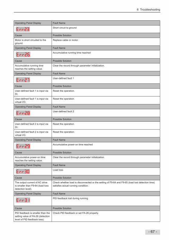
6 Troubleshooting
- 67 -
Operating Panel Display Fault Name
Short circuit to ground
Cause Possible Solution
Motor is short circuited to the ground
Replace cable or motor
Operating Panel Display Fault Name
Accumulative running time reached
Cause Possible Solution
Accumulative running time reaches the setting value
Clear the record through parameter initialization
Operating Panel Display Fault Name
User-defined fault 1
Cause Possible Solution
User-defined fault 1 is input via DI
Reset the operation
User-defined fault 1 is input via virtual I/O
Reset the operation
Operating Panel Display Fault Name
User-defined fault 2
Cause Possible Solution
User-defined fault 2 is input via DI
Reset the operation
User-defined fault 2 is input via virtual I/O
Reset the operation
Operating Panel Display Fault Name
Accumulative power-on time reached
Cause Possible Solution
Accumulative power-on time reaches the setting value
Clear the record through parameter initialization
Operating Panel Display Fault Name
Load loss
Cause Possible Solution
The output current of AC drive is smaller than F9-64 (load loss detection level)
Check whether load is disconnected or the setting of F9-64 and F9-65 (load lost detection time) satisfies actual running condition.
Operating Panel Display Fault Name
PID feedback lost during running
Cause Possible Solution
PID feedback is smaller than the setting value of FA-26 (detection level of PID feedback loss)
Check PID feedback or set FA-26 properly

6 Troubleshooting
- 68 -
Operating Panel Display Operating Panel Display
Pulse-by-pulse current limit fault
Cause Cause
Load is too heavy or locked-rotor occurs on motor
Reduce load or check motor and mechanical conditions
The AC drive power class is small
Replace a drive of larger power class
Operating Panel Display Fault Name
Motor switchover fault during running
Cause Possible Solution
Motor switchover via terminal during drive running of the AC drive
Perform motor switchover after the AC drive stops
Operating Panel Display Fault Name
Motor overtemperature
Cause Possible Solution
Cable connection of temperature sensor becomes loose
Check cable connection of temperature sensor
The motor temperature is too high
Decrease carrier frequency or take other measures to cool the motor
Operating Panel Display Fault Name
Braking unit overload
Cause Possible Solution
Resistance of braking resistor is too small
Replace a braking resistor of larger resistance
Operating Panel Display Fault Name
Short-circuit of braking circuit
Cause Possible Solution
Braking IGBT is abnormal Contact the agent or Inovance

6 Troubleshooting
- 69 -
63 AC Drive Common Symptoms and Diagnostics
Operating Panel Display Fault Description
There is no display while power-on
Cause Possible Solution
The mains voltage is not input or too low Check the power supply
The switching power supply on drive board of the AC drive is faulty
Check bus voltageCheck that the 24V output and +10V output on the control board are normal
Wires between control board and drive board and between control board and operating panel break
Re-connect the 8-pin wire and 40-pin wire
Pre-charge resistor of the AC drive is damaged Contact the agent or Inovance
Control board or operating panel is faulty
Rectifier bridge is damaged.
Operating Panel Display Fault Description
"HC" is displayed while power-on
Cause Possible Solution
Wire between drive board and control board is in poor contact Re-connect the 8-pin wire and 28-pin wire
Related components on control board are damaged Contact the agent or Inovance
The motor or motor cable is short circuited to ground
The hall is damaged
The mains voltage is too low
Operating Panel Display Fault Description
"Err23" is displayed at power-on
Cause Possible Solution
Motor or motor output cable is short circuited to ground Use a megger to measure insulation resistance of motor and motor cable
The AC drive is damaged Contact the agent or Inovance
Operating Panel Display Fault Description
The display is normal while power-on But after running, “HC” is displayed and the drive stops immediately
Cause Possible Solution
The cooling fan is damaged or locked-rotor occurs Replace the fan
Short circuit exists in wiring of control terminals Eliminate short circuit fault in control circuit wiring
Operating Panel Display Fault Description
Err14 (IGBT overheat) is detected frequently
Cause Possible Solution
The setting of carrier frequency is too high Reduce carrier frequency (F0-15)
The cooling fan is damaged, or ventilation is clogged Replace the fan or clean the ventilation
Components inside the AC drive are damaged (thermistor or others)
Contact the agent or Inovance

6 Troubleshooting
- 70 -
Operating Panel Display Fault Description
- The motor does not rotate after the AC drive runs
Cause Possible Solution
It is motor or motor cable problem Check that wiring between AC drive and motor is normal
Related AC drive and motor parameters are set improperly Restore the factory parameters and re-set the following parameters properly:Encoder parametersMotor ratings, such as rate motor frequency and rated motor speedMotor 1 control mode (F0-01) and command source selection (F0-02)F3-01 (torque boost) in V/F control under heavy-load start
Cable connection between drive board and control board is in poor contact
Re-connect wirings and ensure secure connection
The drive board is faulty Contact the agent or Inovance
Operating Panel Display Fault Description
- DI terminals are disabled
Cause Possible Solution
Related parameters are set incorrectly Check and set parameters in group F4 again
External signals are incorrect Re-connect external signal cables
Jumper across OP and +24 V becomes loose Re-confirm the jumper bar across OP and +24 V.
The control board is faulty Contact the agent or Inovance
Operating Panel Display Fault Description
Operating Panel Display Fault Description
- The AC drive detects overcurrent and overvoltage frequently
Cause Possible Solution
Motor parameters are set improperly Set motor parameters or perform motor auto-tuning again
Acceleration/deceleration time is improper Set proper acceleration/deceleration time
Load fluctuates. Contact the agent or Inovance
Operating Panel Display Fault Description
Err17 is detected upon power-on or running
Cause Possible Solution
The pre-charge relay or contactor is not closed Check whether the relay or contactor cable is loose
Check whether the relay or contactor is faulty
Check whether 24 V power supply of the contactor is faulty
Contact the agent or Inovance
Operating Panel Display Fault Description
- The motor coasts to stop or does not have braking capacity during deceleration or deceleration to stop
Cause Possible Solution
Voltage limit is enabled If braking resistor has been configured, it is necessary to set F3-23 = 0 to disable the voltage limit function

Revision History
Revision Date Revising Dept Description
V00 27th NOV’2015 PMT Related firmware version: F7-10 = U29.06 and F7-11 = U29.15
A01 20th Sep' 2016 PMT Add large power rating dataF7-10 = U2907 F7-11 = U2916